Embed Size (px)
Citation preview

©2015 Procella Audio Svenska AB, Procella Audio USA, LLC. All rights reserved. V3.0
System Design White Paper & Installation Handbook
V3.0 – revised January 2015

3
©2015 Procella Audio Svenska AB, Procella Audio USA, LLC. All rights reserved. V3.0
Table of Contents
BACKGROUND
1. Contact Information 2
2. Procella History and Technology 5
SYSTEM DESIGN
3. System Design Parameters and Considerations 8Room Design and Acoustic Treatment 8Listening Distance – Main and Surround Speakers 8Room Volume – Subwoofers 9Recommended Amplifier Power by Speaker Model 10THX Approval and THX Certified Screening Rooms 103D Audio (Dolby Atmos, DTS:X, Auro 3D) 11
4. Selecting the Proper Procella Speaker Models 12Screen Channel Speaker 12Surround Channel Speaker 12Subwoofer 13
5. Positioning of Procella Speakers 15Speaker Setup 15Recommended Speaker Positioning for Film 16Screen Channel Speakers 18Surround Speakers 18
6. THX Baffle Wall Design and Construction 20
SPEAKER INSTALLATIONPlease note: some of the information presented here is duplicated from model to model. This section is organized sothat the content for each product is self-contained and does not require reference to other parts of this document.
7. P5 Installation Guidelines 24
8. P6 and P6V Installation Guidelines 26
9. P6iW Installation Guidelines 29
10. P8 Installation Guidelines 32
11. P28 Installation Guidelines 34
12. P610 Installation Guidelines 36
13. P815 Installation Guidelines 38Using P815-FP with the Procella DA-2800 Outboard Amplifier 40

4
©2015 Procella Audio Svenska AB, Procella Audio USA, LLC. All rights reserved. V3.0
14. P860 Installation Guidelines 41
15. P10, P12, P15, P18, P10Si Subwoofer Installation Guidelines 43Location of the Subwoofer(s) 43Multiple Subwoofers 44Using P18-FP, P15-FP, P10-FP with the Procella DA-2800DSP Outboard Amplifier 47
16. P10Si Installation Guidelines and Balancing Subwoofers 48
17. Wall Mounting the P6/P6V, P8, and P5 50Wall Mounting the P5 51
AMPLIFIERS, CONNECTIONS AND CALIBRATION
18. Procella DSP and Amplifier Controls: P815, P10, P15, P18 53P18, P15 and P10 Subwoofers 54P815 Main Speaker 54P12 Subwoofer 55
19. Procella DA-2800 2,800 Watt Four-Channel Power Amplifier 57DA-2800 DSP Speaker & Subwoofer Amplifier Channel Requirements 57DA-2800 DSP Speaker Configurations and DSP Presets 59
20. Cables and Connectors 60XLR Connector Wiring 60
21. AC and Grounding Requirements and Troubleshooting 61
22. Bass Management and Surround Processor Settings 63
TECHNICAL SPECIFICATIONS AND DIMENSIONS23. Appendix A
Product Technical Specifications and Dimensional Information 64

Background
5
©2015 Procella Audio Svenska AB, Procella Audio USA, LLC. All rights reserved. V3.0
2. Procella History and Technology
DTS Theatre with the very first Procella Audio system
Procella Audio was launched in the U.K. in 2006, founded by Anders Uggelberg and Gerben VanDuyl. At that time, Anders was Director of Cinema Technology for DTS Europe, and Gerben wasDTS‘s European Director of Business Development for Consumer Technology.
While at DTS, Anders, a THX trained and certified cinema designer with over 300 cinema andprofessional studio designs to his credit, was asked to design and build a state-of-the art in-house32 seat preview theater at the DTS Europe headquarters just outside London. Teaming up withGerben, the goal was to create a theater able to produce reference sound quality for playback of allcurrent and future cinema and home entertainment media, including the upcoming Digital Cinema(DCI) standard, Blu-ray disc and other 24 bit/96KHz resolution playback systems. Of particular notewas the use of the theater for multi-channel music demonstrations to artists such as Queen andDepeche Mode, in order to persuade them to have their own recordings remixed to 5.1. Aftertaking an exhaustive survey of available speaker systems, the duo determined that no existingsystem could deliver the requisite high-resolution audio with uniform coverage to all 32 seats.
To meet these requirements, Anders designed a new speaker system that became the basis for thecurrent Procella systems. Nimbly balancing the requirements of the cinema and homeentertainment sides of DTS audio, Anders’ design accommodates both with equal capability andprowess. Taking the best elements of cinema speaker design and applying the performancestandards and design elements of the best small studio and high-end audio loudspeakers, theProcella system delivers high-resolution audio to each and every seat in the room. Once the design

Background
6
©2015 Procella Audio Svenska AB, Procella Audio USA, LLC. All rights reserved. V3.0
was finalized, the speakers were installed in the new DTS theatre in the summer of 2005 andcontinue in operation there today.
To say the system was well received would be an understatement. Following the enthusiasticapproval of artists, engineers and producers that experienced and used the DTS system in theirprofessional capacity, Anders and Gerben realized the great commercial potential of the speakers,leading to their departure from DTS and the creation of Procella Audio.
DTS Theatre with the first Procella speakers in screen baffle wall
The original DTS system, which has evolved through several iterations into today’s P815, P8 andP18 loudspeakers, established the core principles of all Procella systems:
Identical Voice™
All screen and surround channel speakers are critically timbre matched, providing 'identical voices'around the room, regardless of the number of speakers or Procella models used.
High Frequency Compression Drivers
Compression drivers are used exclusively for high frequencies because of their wide dynamic range,high output levels and low distortion, particularly when compared to soft-dome tweeters.
Constant Directivity Waveguides
Each speaker utilizes a Procella-designed waveguide, which, along with carefully selected crossoverfrequencies, produces constant power response with superior dispersion characteristics anduniform coverage over a large seating area.
Advanced Crossover Designs
Procella-designed crossovers exhibit flat phase response and ultra-low group delay, with distortion-free air core inductors and polypropylene capacitors for maximum sonic purity.

Background
7
©2015 Procella Audio Svenska AB, Procella Audio USA, LLC. All rights reserved. V3.0
Digital Signal Processors (DSP)
All Procella active speaker models provide DSP control for very detailed fine-tuning of theacoustical result in a variety of room boundary conditions, making for great flexibility in systemdesign and installation.
Sealed-Box Cabinets
All Procella speakers, including subwoofers, use sealed cabinets for superior transient response andgroup delay characteristics, as well as extended low-frequency subwoofer response.
Dual-Driver Dual-Amp Subwoofers
Each Procella main subwoofer uses two identical drivers, each driven by its own amplifier channel,for high efficiency, low distortion and 6 dB greater output than a subwoofer using just one driver.

System Design
8
©2015 Procella Audio Svenska AB, Procella Audio USA, LLC. All rights reserved. V3.0
3. System Design Parameters and ConsiderationsThis section discusses the elements that should be taken into consideration when designing aProcella Audio system. We encourage dealers and system designers to contact us in advance whenconsidering the use of Procella loudspeakers. We are happy to review system plans incorporatingProcella loudspeakers and to make suggestions for the appropriate Procella models.
Room Design and Acoustic Treatment
Room design and acoustic treatment of both purpose-built and existing theater rooms is a complexsubject, and we are not going to address it in detail within this document. Systems incorporatingProcella Audio loudspeakers will reap an enormous benefit from proper room design and acousticaltreatment, so we strongly recommend that room treatment be an integral part of any project’sdesign and budget. Proper room treatment is not just acoustical foam; it involves structural designand a proper understanding of absorption and diffusion, among many other things.
One note of guidance: Procella speakers use waveguides, rather than dome tweeters, which meansthat the off-axis high-frequency energy they produce is much more uniform in frequency responsethan the off-axis signals produced by most speakers. For acoustical treatment, this enables the useof more diffusion and less absorption than designers typically must use with other speakers, andthis can produce better sonic results.
For dealers that do not have experience with room design and advanced acoustical roomtreatment, engaging the services of an experienced acoustical designer can be invaluable. We canrefer dealers to designers that are familiar with Procella speakers. Also, subject to the timeavailability of Procella engineers, we can also provide design services. This service will be providedat a reasonable cost depending on the scope of a given project and the time required. Pleasecontact us for more details.
Listening Distance – Main and Surround Speakers
To start, let’s look at some key dimensions in the room where the system will reside. While overallroom dimensions are important, the initial consideration should be the distance from the speakersto the listeners’ seats. This distance is the key factor in determining which loudspeakers should beused for screen and surround channels and how much amplifier power will be needed to achievethe desired playback levels and dynamic range available for each listener. Subwoofer requirementsare primarily determined by the overall room dimensions and volume rather than the distance toany given seat, and we will discuss subwoofers separately.
The direct sound power level produced by a speaker decreases as the inverse square of thedistance from the speaker. Simply put, each time you double the distance from a speaker, in freefield, the SPL will decrease by 6 dB (reduce the distance by half, and the level increases by 6 dB). Inrooms with multiple rows of seats, the direct SPL heard in the front row will therefore be higher

System Design
9
©2015 Procella Audio Svenska AB, Procella Audio USA, LLC. All rights reserved. V3.0
than the SPL heard in the back row. This means that in rooms with multiple rows of seats,consideration should be given to the level that can be achieved in each row.
The reference level standard for cinema presentation, as defined by THX, requires each screenchannel to individually produce a level of 105 dB of direct sound at the listening position. The 105dB level is based on two factors:
- all film sound mix facilities worldwide use an identical reference level of 85 dB for dialog whenmixing soundtracks, and
- the maximum channel signal level on digital film soundtracks is +20 dB (U.S. standard) and +18 dB(European standard) higher than the dialog reference level, which is therefore 105 dB U.S. and 103dB European.
That means that the creative team working on any film, worldwide, is able to create a soundtrackwith playback levels reaching as high as 105 dB per channel, with the knowledge that thesoundtrack will be reproduced at the same SPL they experienced during the mix, every time thefilm is screened in a properly calibrated theater.
When all channels are playing back at maximum level, the total output is approximately another 5dB, for a total of 110 dB!
The general rule for professional cinemas is that the sound system should be able to achievereference level to about 2/3 the depth of the room. This is a good standard for system design inhigh-performance home cinema systems.
105 - 110 dB is quite loud, and therefore not all clients will require this full capability, particularlywhen there are room and budget limitations. For example, the client installing a P6 system in anapartment living room is unlikely to have the same expectations as a client building a new,dedicated home cinema room or a professional screening room. These considerations should beexplored with the client as the system is being designed.
To determine the listening distance, measure from the front baffle of the center channel speaker tothe appropriate seat and/or to the 2/3 point of the room depth. The next section of this guideincludes a speaker selection chart that identifies the range of listening distances and powerrequirements that will produce optimal performance with each Procella model used for screen andsurround channels.
Room Volume - Subwoofers
The second primary room dimension is room volume. Room volume is used generally to determinesubwoofer requirements, including specific models and (if more than one is necessary or preferred)the total number of subwoofers needed for a system. In many rooms, volume is related to thelistening distance from the screen speakers to the seats, but in some cases (such as a large multi-purpose room with the theater space at one end) it may not.

System Design
10
©2015 Procella Audio Svenska AB, Procella Audio USA, LLC. All rights reserved. V3.0
To assist in selecting the correct Procella subwoofer model for each application, we will use cubicvolume. The goal is to help determine the minimum number of Procella subwoofer(s) and modelappropriate for a room. Room dimensions, acoustics and room treatments will affect subwooferrequirements, sometimes to a great extent, so be aware that there is no universal formula forcalculating subwoofer requirements. We strongly recommend using at least the minimumsubwoofer recommendation per the Subwoofer chart on page 14, and always encourage the use ofmultiple subwoofers. Having extra low-end capability will always be welcome, while insufficientbass invariably produces constant listener disappointment. In every case, additional subwooferscan not only produce greater output, but when they are deployed in multiple locations, theconsistency of frequency response across the seating area can be improved.
For more details and information on choosing the Procella subwoofer for a specific application, seethe Subwoofer section on page 13.
Recommended Amplifier Power by Speaker Model
Five Procella models have onboard amplifier options, meaning that the appropriate amplifierpower needed to provide enough headroom for maximum speaker performance is already present.The P610, P28, P8, P6/6V/6iW, P5 and P10Si are passive, as are the FP versions of the amplifiedspeakers, and therefore require an external power amplifier or receiver. We strongly recommendthe use of the Procella DA-2800 2,800 Watt Four-Channel Power Amplifier for all Procella speakers.See Section 19 on page 57 for more information.
In order to achieve the maximum dynamic range, we always recommend using the maximumamount of amplifier power that fits a project’s budget. Minimum power ratings are as follows:
P5 75 Watts continuous minimumP6/6V/6iW 100 Watts continuous minimumP8 150 Watts continuous minimumP28 200 Watts continuous minimumP610 100 Watts continuous minimum for HF 250 Watts continuous minimum for LFP815-FP 150 Watts continuous minimum for HF 350 Watts continuous minimum for LFP860 300 Watts continuous minimum for HF 900 Watts continuous (300W x 3) for LFP10-FP 350 Watts continuous total (paralleled inputs) or 175 Watts continuous per driverP15-FP 500 Watts continuous total (paralleled inputs) or 250 Watts continuous per driverP18-FP 1500 Watts continuous total (jumpered inputs) or 750W continuous per driverP10Si 250 Watts continuous minimum
THX Approval and THX Certified Screening Rooms
The P815, P8 and P18 have all earned THX Approval for integration into professional facilities,including THX Approved Screening rooms and pm3 rooms (Professional Multichannel Mixing andMonitoring). Products that receive THX Approval go through a process distinct from products thatreceive THX Certification. THX Certified products are designed for consumer applications, which

System Design
11
©2015 Procella Audio Svenska AB, Procella Audio USA, LLC. All rights reserved. V3.0
generally means that they meet THX requirements in rooms that are smaller than the rooms whereTHX Approved products must perform.
THX Approval of the P815, P8 and P18 enables their use in THX Certified Screening Rooms forresidential applications, as well as professional facilities. Integrators and clients interested increating a THX Certified Screening Room using Procella loudspeakers should contact us for moreinformation and assistance.
3D Audio (Dolby Atmos, DTS:X, Auro 3D)
At Procella, we have been eagerly anticipating the availability of 3D Audio for the home cinema.This breakthrough technology elevates the cinema experience to a new level of immersion andcreates new opportunities for multiple entertainment platforms including music. The fact thatthree formats have been introduced to the consumer market indicates the depth of interestcoming from both the business and pro audio communities.
For 3D Audio, all existing Procella speaker models can be used as side and height channels whenmounted on side walls. For overhead channels, any Procella loudspeaker can be used whenproperly mounted, but we recommend in particular two models that have been optimized for useas overhead speakers. Both the P6iW in-wall/in-ceiling speaker and the P5 speaker were designedwith overhead mounting for 3D Audio in mind.
One of the primary requirements for overhead speakers is wide dispersion, which is essential forproper coverage and timbre-matching to all seats in the listening area. Conventional speakers usingdome tweeters have inherent limitations that makes this very difficult. However, because both theP5 and the P6iW utilize circular waveguides for high frequencies, they produce a near-ideal circulardispersion pattern when pointing straight down – essentially an 80 degree cone of sound.Following the Procella ‘Identical Voices’ concept, this means that each listener hears a tonalbalance from the overhead speakers nearly identical to all the other speakers in the system.
The P8 and P6/P6V speakers have an elliptical waveguide with vertical dispersion narrower thanDolby recommendations. When they are used as overhead speakers, they should be angledtowards the listening position. In the case of the P8, its front baffle is angled at 7 degrees, meaningit can be pointed at the listeners even when the speaker’s back baffle is mounted flush to theceiling.
Deciding on speaker placement can be rather complicated, because each format has its ownrecommended layout. So, rather than summarizing the recommendations for each format here, weencourage you to consult the documentation provided by each format creator. For individualsystem design and speaker placement, feel free to contact us, as always. We are happy to consultwith you to get the best result for each system.
System Design
12
©2015 Procella Audio Svenska AB, Procella Audio USA, LLC. All rights reserved. V3.0
4. Selecting the Proper Procella Speaker ModelsThe guidelines below show recommendations for Procella speaker as determined by therequirements described above. Screen Channel recommendations are presented on the basis ofboth listening distance and room depth.
Screen Channel Speaker:Selection by Listening Distance(front baffle of center channel speaker to the seat)
For THX Reference Level PlaybackUp to 2 meters (6½ feet) P6, P6V, P6iWUp to 4 meters (13 feet) P8 (80 Hz crossover), P610 (full-range)Up to 8 meters (26 feet) P815, P28Up to 16 meters (53 feet) P860
For Standard PlaybackUp to 3 meters (10 feet) P6, P6V, P6iW, P5 (120 Hz crossover)2 meters to 6 meters (6½ to 20 feet) P8 (80 Hz crossover), P610 (full-range)5 meters to 12 meters (16½ to 40 feet) P815. P287 meters to 24 meters (23 to 80 feet) P860
Screen Channel Speaker:Selection by Room Depth(dimension from front or screen wall to back wall)
For Standard PlaybackUp to 6 meters (20 feet) P6, P6V, P6iW, P5 (120 Hz crossover)4 meters to 9 meters (13 to 30 feet) P8 (80 Hz crossover), P610 (full-range)7 meters to 15 meters (20 to 50 feet) P815, P2810 meters to 24 meters (33 to 80 feet) P860
Surround Channel Speaker:Selection by Screen Channel Speaker and Width of Room
P5 Screen Channel speaker Use P5 for all surrounds
P6/6V/6iW Screen Channel speaker P6/6V/6iW is optimalP5 can be used as side surrounds where the room isless than 5 meters (15 feet) wide and as back

System Design
13
©2015 Procella Audio Svenska AB, Procella Audio USA, LLC. All rights reserved. V3.0
surrounds when the front row of seats is less than 5meters from the back wall
With the P8 Screen Channel speaker P8 is optimal
P6/6V/6iW can be used as side surrounds when theroom is less than 6 meters (20 feet) wide and as backsurrounds when the front row of seats is 6 meters (20feet) or less from the back wall
With P610 Screen Channel speaker P6/6V/6iW should be used as side surrounds when theroom is less than 6 meters (20 feet) wide and as backsurrounds when the front row of seats is 6 meters (20feet) or less from the back wall
P8 should be used as side surrounds when the room isgreater than 6 meters (20 feet) wide and as backsurrounds when the front row of seats is 6 meters (20feet) or more from the back wall
With P815 Screen Channel speaker P8 is strongly recommended
P6/6V/6iW is acceptable as side surrounds when theroom is less than 6 meters (20 feet) wide and as backsurrounds when the front row of seats is 6 meters (20feet) or less from back wall
With P860 Screen Channel speaker Use P8 for all surrounds.In extremely large rooms, the P28 can be used.
Subwoofer:Selection by Room Volume and Room Conditions
The P15 is designed to produce +6 dB more output than the P10 and P12.The P18 is designed to produce +6 dB more output than the P15.The P18 is designed to produce +12 dB more output than the P10 and P12.The P10Si is designed to work as a balancing sub in conjunction with P18, P15 or P10 subwoofersand therefore should not be taken into account in determining system low frequency outputcapability.

System Design
14
©2015 Procella Audio Svenska AB, Procella Audio USA, LLC. All rights reserved. V3.0
Room Volume
These recommendations are for subwoofers in rooms with a medium low frequency reverb time.Understand that these are guidelines, not precise specifications. Room construction, dimensionsand acoustics vary considerably from room to room, making it difficult to reduce subwooferselection to a simple formula. Experience counts; contact us if you have questions.
P10 and P12 P15 P18
One subwoofer up to 50m³ (1750 ft³) up to 100m³ (3500 ft³) up to 200m³ (7000 ft³)
Two subwoofers up to 100m³ (3500 ft³) up to 200m³ (7000 ft³) up to 400m³ (14000 ft³)
Three subwoofers up to 150 m³ (5250 ft³) up to 300m³ (10500 ft³) up to 600m³ (21000 ft³)
Four subwoofers up to 300 m³ (10500 ft³) up to 600m³ (21000 ft³) up to 1200m³ (42000ft³)
Room Conditions
The amount of low frequency loss, absorption and reverb in a given room can affect subwooferrequirements. Rooms with low reverb time and/or low frequency loss will need more subwoofersand rooms with long low frequency reverb times will have greater problems with standing wavesand resonances.
In general, the smaller the room, the more pronounced the problems.
We recommend use of multiple subwoofers when possible, with four properly placed subwooferstypically producing the best ratio of performance to cost. Subwoofer models may be mixed in aroom, meaning that P10s can be used as additional ‘balancing’ subwoofers in combination withP18s or P15s used as the main subwoofer(s). The P10Si balancing subwoofer can be used incombination with any Procella main subwoofer.
Some rooms can be considered ‘lossy’ at low frequencies because of the room design andconstruction. This can occur in rooms where construction is not rigid, or when rooms have a largenumber of windows, doors or open walkways. In some cases, lossy rooms produce better bassquality than stiffly constructed rooms, because of reduced room mode effects. However, the loss ofbass energy must be compensated for with additional or larger subwoofers.
Low frequency absorption, when properly applied through room design and/or acousticaltreatments, is desirable as a way to avoid excessive nodes. This can be accomplished through theuse of techniques that include bass trapping. This is an area where the guidance of an experiencedand knowledgeable acoustician can be very beneficial.
When adding low frequency absorption to a room, bear in mind that the overall low frequencyenergy in the room will be reduced. This may change the total subwoofer requirement and shouldbe considered when determining the models and quantities of subwoofers that you will use.

System Design
15
©2015 Procella Audio Svenska AB, Procella Audio USA, LLC. All rights reserved. V3.0
5. Positioning of Procella SpeakersCareful attention to optimal room positioning will help ensure maximum performance fromProcella speakers. This attention should be paid in the earliest stages of the system design process,well in advance of the actual installation.
Here, we will first discuss location of the speakers in the room, using cinema design guidelines andrecommendations from Dolby and THX. While the ideal theater environment is a purpose-builtroom, for most installations the location of speakers will be dictated by room structure and/or theowner’s preference. As a general guideline, Procella speakers should be placed in locations as closeas possible to the ideal ones discussed here.
With the exception of the P6iW and the P5, Procella speakers are designed for a verticalorientation and should always be mounted accordingly. Procella’s constant directivitycharacteristics are optimized for this orientation. The cabinet should be placed with the tweeterabove the woofer except in very rare instances (please consult us before doing this), and the P8and P6 should never be oriented on their sides. The P6iW and P5 use a circular waveguide thatproduces a symmetrical horizontal and vertical radiation pattern, and therefore can be orientedeither horizontally (wide) or vertically (tall). This circular radiation pattern is ideal for overheadspeaker use in 3D Audio systems, so the P6iW and P5 are highly recommended for this application.
Because the P860, P815 and P610 use separate cabinets for low and high frequencies, it isacceptable to place those cabinets side by side, as long as the separation is less than half a meter.
Speaker Setup
Our speaker setup recommendations follow cinema industry practices as used for playback in first-run cinemas and in the professional dubbing stages where film soundtracks are created by mixersand sound designers. Some mixers of multichannel music content use an alternate setup, which wewill discuss first for comparison’s sake and to provide an option for those that may have apreference or need for this setup.
Speaker Layout for Multichannel Music: the ITU-R BS.775-1 Standard
The speaker configuration for the mixing of multichannel music recordings is often different fromthe configuration used for film sound mixing. We’ll review the typical configuration for musicmixing here to give you some perspective and understanding of the differences.
Music mixers often set up their speakers so that the mix position is an equal distance from everyloudspeaker, with only one speaker used for each channel. As this is only possible for one seat andone listener, this condition typically exists only in recording studios and specially configured rooms.Film mixers, however, work with arrays of surround speakers, as in the typical cinema. There is arecommended standard for music mixing, known as the ITU-R BS.775-1 Standard for multichannelstereophonic sound systems with and without picture.

System Design
16
©2015 Procella Audio Svenska AB, Procella Audio USA, LLC. All rights reserved. V3.0
Many professional recording facilities, primarily in the music field, use this standard forloudspeaker placement. The speakers are placed at an equal distance from the mix position, withthe center speaker directly in front of the listener and the left and right speakers placed at 30degrees to either side of the center. Shown here for multichannel playback, this 30 degree spacingbetween left and right speakers is common for monitoring of two channel material as well. Thesurround speakers are placed at an angle of 110 degrees to the center, although a range from 100to 120 degrees is acceptable.
This configuration is generally not used for film soundmixing or playback because it uses a 60 degree widespacing between the front left and right channels.Typical film sound practice is to use a 45 degree widespacing between left and right speakers, and this is ourrecommendation for home cinema playback. In somecases, though, where the primary focus is on musicplayback, whether two channel or multichannel, the 60degree spacing may be useful.
In home systems, the need to have speakersequidistant from the listening position is alsonot critical, as surround processors andreceivers have time delays that provide forcoincident arrival of sound from all speakersregardless of their distance from the listeningposition. In any case, there are clear benefitsto symmetrical location of loudspeakers.
When a Cinemascope 2.35:1 or wider screen isused, the left and right speakers should belocated behind the screen. Keep in mind the45 degree angle from the listening position tothe left and right speakers described above. Ifthe spacing between the left and rightspeakers is too close to accommodate anarrower screen aspect ratio such as 16:9 or4:3, the full sonic impact of the widest screenformat will be diluted. When masking is usedfor narrower screen sizes, it is very important that the masking be acoustically transparent.
Recommended Speaker Positioning for Film
The speaker setup for film sound in home cinemas and screening rooms places the speakers atdifferent angles to the listening position than the multichannel music configuration. The layout

System Design
17
©2015 Procella Audio Svenska AB, Procella Audio USA, LLC. All rights reserved. V3.0
shown at right shows the range of recommended speaker angles for 5.1 and 7.1 channelconfigurations. These recommendations incorporate the guidelines promulgated by DolbyLaboratories and THX.
Starting with the center channel at the 0 degree position, the left and right channel speakersshould each be placed at a 22.5 degree angle to the left and right, respectively, which forms a total45 degree angle between the speakers at the listening position. The diagram shows an acceptablerange of 22 to 30 degrees. While we recommend the 22.5 degree position for film playback, thediagram shows the 30 degree options to illustrate the positions typically used for music playback,either in stereo or in the ITU-R BS.775-1 Standard setup described above.
The side surround speakers are shown at a minimum of 90 degrees from the listening position for a5.1 channel system where these are the only surrounds. The acceptable range is between 90 and110 degrees. THX recommends positioning the speakers between 90 and 110 degrees, and Dolbyrecommends they be placed between 100 to 110 degrees. We recommend that the surrounds beplaced so that they are just behind the listeners’ ears, meaning an angle a little greater than 90degrees.
In a 7.1 channel system, the side surrounds should also be located as shown on the layout, with theDolby recommendation between 90 and 100 degrees, and THX saying that 90 to 110 degrees isacceptable. Again, we recommend an angle a bit greater than 90 degrees.
When there are multiple rows of seats, the ideal design is to have a set of side surrounds for eachrow, with each speaker located just behind the listeners ears (greater than a 90 degree angle),along with a pair on the back wall. If this is not possible, then the side surrounds should bepositioned symmetrically along the side wall over the depth of the seating area as measured fromthe center of the front row to the center of the back row.
Placement for the back surrounds in 7.1 channel systems variesaccording to the application. The adjacent layout at left shows a60 degree angle between the back surrounds and the mainlistening position. This location is identical to the 150 degreeposition shown in the diagram above. This 60 degree spacing isthe recommended location for recorded material in discrete 7.1channel formats such as Dolby TrueHD and DTS Master Audio.
For material where the back surround channels are not discrete,when using a THX processor, the back surrounds should be placedclose together as indicated in thediagram at right. Since this is notthe ideal location for playback ofthe latest high-resolution audio
formats, you will have to decide whether to optimize for legacyfilm playback or for the current state of the art. We suggest usingthe 60 degree spacing to provide optimal playback for the highest-

System Design
18
©2015 Procella Audio Svenska AB, Procella Audio USA, LLC. All rights reserved. V3.0
resolution audio material.
Screen Channel Speakers
Maximum cinema sonic impact and effectiveness is achieved with an acoustically transparentscreen and screen channel speakers mounted behind the screen in a baffle wall.
The screen channel speakers are ideally placed where their tweeters are on the same lateral plane.The center channel can be placed at a different height than the right and left speakers, but imagingwill be improved when all three speakers are at the same height. When a choice must be madebetween locating the speakers above or below a screen, the vertical listening window is greaterbelow the speaker than above the speaker. The optimized vertical window for Procella speakersextends from 5 degrees above the high frequency driver to 30 degrees below. This providesexcellent sound quality for listeners when the speakers are located behind an acousticallytransparent screen at the recommended location of 5/8 of the screen height, which will be abovemost listeners’ ears.
Any time an acoustically transparent screen is used, a baffle wall should be constructed to mountthe speakers. Please see Baffle Wall Design and Construction on page 20 for more information onbaffle walls and their construction.
A baffle wall can also be used with a solid projection screen or flat panel display device. In this case,the wall surface exposed to the room is covered by fabric, and the front speakers are concealedbehind that fabric and not behind the screen. The tradeoff here is that the center channel speakerwill have to be located either above or below the screen. While this will shift the image location ofthe center channel, all of the other benefits of a baffle wall remain. For these installations, werecommend that, where possible, the left and right screen speakers be placed at the same heightas the center channel, preferably above the screen or display. This configuration will produce thebest imaging.
Whenever the speakers are mounted behind a screen or behind fabric used to conceal thespeakers, the grilles should be removed from the speakers.
Surround Speakers
Following the Identical Voice concept and cinema practices, Procella surround speakers are directradiators. We do not offer or recommend using dipoles or other speaker configurations, as theseviolate the Identical Voice philosophy and do not meet cinema and music industryrecommendations for playback of discrete multichannel film and music sources, which specify useof direct radiator speakers.
The ideal system configuration would use identical speakers for all channels. However, as this isoften not practical, Procella’s Identical Voice concept means that any combination of Procellaloudspeakers – P860, P815, P610, P28, P8, P6/6V/6iW, or P5 can be used to produce excellentresults. For example, P8s perform superbly as surrounds when P860s, P815s, P610s, or P28s are

System Design
19
©2015 Procella Audio Svenska AB, Procella Audio USA, LLC. All rights reserved. V3.0
used for screen channels, and P6/6V/6iWs are similarly excellent as surrounds with P610, P28, orP8 screen channel speakers. The P5 can be used with P6/6V/6iW or P5 mains, and may also besuitable for use as height channels because of their compact size.
See the Recommended Speaker Positioning for Film section on page 16 for more details regardingroom location of surround speakers. Typically, they should be mounted at a height about two feetabove the listeners’ heads. When there are multiple side surround speakers, each should bemounted at the same distance from the floor (not ceiling) so that they are at the same relativeheight for each listener. Always take care to place the speakers so there is sufficient clearance inwalkways to avoid the risk of head injury in a darkened room.
When there are multiple rows of seats, the ideal setup is to have a set of side surrounds for eachrow, with each speaker at an angle slightly greater than 90 degrees relative to the row. If this is notpossible, then the side surrounds should be positioned symmetrically along the side wall to coverthe depth of the seating area as measured from the center of the front row to the center of theback row, with each speaker pointed to the ear height of a listener in the most distant seat in therow just behind the speaker.
System Design
20
©2015 Procella Audio Svenska AB, Procella Audio USA, LLC. All rights reserved. V3.0
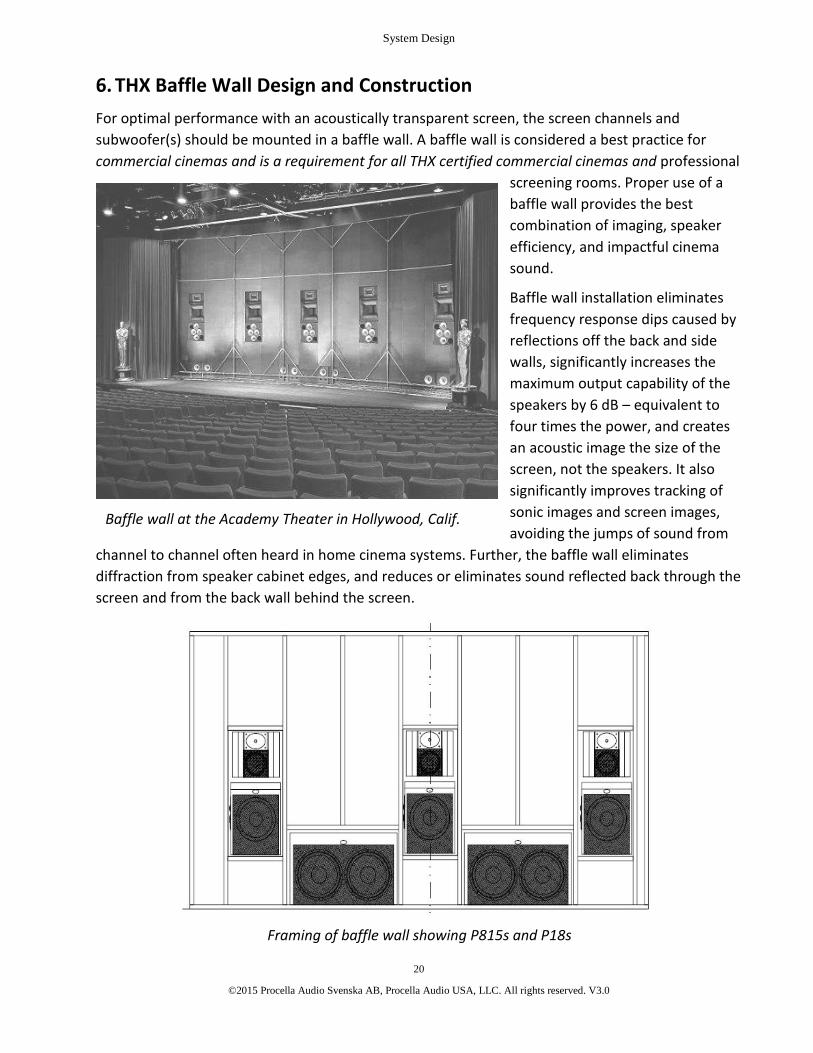
Framing of baffle wall showing P815s and P18s
6. THX Baffle Wall Design and ConstructionFor optimal performance with an acoustically transparent screen, the screen channels andsubwoofer(s) should be mounted in a baffle wall. A baffle wall is considered a best practice forcommercial cinemas and is a requirement for all THX certified commercial cinemas and professional
screening rooms. Proper use of abaffle wall provides the bestcombination of imaging, speakerefficiency, and impactful cinemasound.
Baffle wall installation eliminatesfrequency response dips caused byreflections off the back and sidewalls, significantly increases themaximum output capability of thespeakers by 6 dB – equivalent tofour times the power, and createsan acoustic image the size of thescreen, not the speakers. It alsosignificantly improves tracking ofsonic images and screen images,avoiding the jumps of sound from
channel to channel often heard in home cinema systems. Further, the baffle wall eliminatesdiffraction from speaker cabinet edges, and reduces or eliminates sound reflected back through thescreen and from the back wall behind the screen.
Baffle wall at the Academy Theater in Hollywood, Calif.

System Design
21
©2015 Procella Audio Svenska AB, Procella Audio USA, LLC. All rights reserved. V3.0
The method described here is generally considered a standard for baffle wall construction.However, we recognize that there are alternate methods practiced by some designers that alsoproduce excellent results. These include (but are not limited to):
Segmented walls with one section per screen speaker. They may be connected or separate, and theleft and right may be angled to provide a toe-in. This is also an option with curved screens.
Curved baffle walls, which provide toe-in and can be used with curved screens.
Partial baffle walls that do not span from floor to ceiling can provide many of the benefits.
The baffle wall should be constructed on a frame of 2x4s, with at least two layers of gypsum board(sheetrock), and a third top outer layer of a solid sheet material (preferably MDF). It should spanfrom wall to wall and floor to ceiling. Make certain that it is very rigid. The total thickness should beat least 1.5”, and the surface layer must be covered with material that is acoustically absorbent andcompletely black, with an additional thickness of 1 - 1.5”. Be sure to acoustically treat the spacebehind the baffle wall to eliminate resonances.
Three sources of materials suitable for acoustic treatment of the baffle wall surface are:
USA: Owens Corning SelectSound Black Acoustic Board -www.owenscorning.com/around/sound/commercial_acoustics/black-acouboard.asp
USA: CertainTeed AcoustaBoard / ToughGard Rigid Liner Board -http://www.certainteed.com/products/insulation/fiber-glass-insulation/board-products/317353
Europe: Saint-Gobain Ecophonhttp://www.ecophon.com/en/products/Vertical-applications/Akusto/Akusto--Wall-A/
Baffle wall before installation of acoustical absorber treatment

System Design
22
©2015 Procella Audio Svenska AB, Procella Audio USA, LLC. All rights reserved. V3.0
For each screen speaker, a cutout must be made appropriate for thedimensions of the speaker. The baffle wall cutout dimensions for eachProcella model can be found on the individual tech sheets located inAppendix A of this document. For height, the speakers should belocated so that their acoustic centers (the line at the lower edge of thewaveguide and the top of the grille) are at 5/8 of the distance fromthe bottom of the screen to the top. Avoid locating the right and leftspeakers too close to the side walls. Make sure you have the correctlocations – you won’t be able to move the speakers once they areinstalled!
There should also be a cutout for mounting the subwoofer(s), whichshould be located in the baffle wall and resting on the floor to takeadvantage of room loading. Do not locate the subwoofer in the centerof the baffle wall. It should be offset to one side or the other. If two
subwoofers are used, they should be an asymmetrical distance from the center of the baffle walland from the right and left room walls.
Support for the screen speakers must be provided by platforms mounted to the baffle wall frame.These platforms, or shelves, must be absolutely horizontal, have sufficient strength to support theweight of the speakers and have enough solidity to be completely free from vibration and rattles.All screen mounts also need to be secure and rattle and vibration-free. Do not create an enclosurearound the speaker – only a shelf for it to rest on. Use the provided Procella insulation feet for eachspeaker, which go between the speaker and the platform/shelf. The subwoofer(s) should also bemounted on Procella insulating feet.
Completed Procella baffle wall at CEDIA Expo with wood blocks for screen mounting

System Design
23
©2015 Procella Audio Svenska AB, Procella Audio USA, LLC. All rights reserved. V3.0
When the left and right speakers are placed ontheir platforms, they should be toed-in slightlytowards the center line of the room, with agreater angle for small rooms and a lesserangle for large rooms. Make sure you removethe grilles any time that speakers are locatedbehind a screen, and in any case where theywill be located behind a fabric wall surfaceused to conceal the speakers. We also stronglysuggest that the speakers be secured to theback wall of the room with heavy-gauge wire orthe equivalent.
Make certain that the wall opening around thespeakers is filled and resilient, meaning thatonce the speakers are in their final location, thegaps between the speakers and the cutout in the baffle wall should be gasketed with soundabsorbing material such as insulation or dense foam. The space does not need to be sealed; justfilled.
Take care to see that the subwoofer does not cause any rattles bybeing in contact with the baffle wall, the frame supporting the fabricon the face of the wall, the screen, or any other object. Procellasubwoofers generate a lot of energy, so be sure to test for this onceeverything is in place.
You must allow for air circulation and access to the amplifier/controlpanels when using the P815 and for each subwoofer model. Theamplifier panels for all models are located on the left side of thecabinets when viewed from the front. The P815, P18, P15 and P10also have ventilation holes on the left side of the cabinet, both aboveand below the amplifier panel. In addition, the P815 and P18 have a quiet temperature-controlledcooling fan that will activate as needed.
Alternative to a Baffle Wall
When it is not possible or practical to construct a full baffle wall, a less complicated option thatprovides many of the benefits of a baffle wall can be achieved by flush-mounting the speakers onthe existing front wall of the room and treating that wall with the acoustic treatment materialsdescribed above. The material should be at least 2 inches and preferably 4 inches deep, and shouldcover the entire wall with the exception of the speaker front baffles and the screen. The wall canbe covered with acoustically transparent fabric to conceal the absorbing material and the speakers.
Rear view showing speaker platforms

Speaker Installation
24
©2015 Procella Audio Svenska AB, Procella Audio USA, LLC. All rights reserved. V3.0
7. P5 Installation GuidelinesThe P5 is designed for wall mounting and stand/shelfmounting on or next to a wall. Ideally, the back of thespeaker should be one to five inches from the wall. TheP5 uses a circular waveguide, which means that thespeaker can be oriented either vertically (tall) orhorizontally (wide). When the speaker is not flushmounted on a wall, the front left and right speakerscan be toed in towards the center of the room foroptimal imaging.
For the best sound quality, the vertical angle betweenthe location of the tweeter and the listeners’ earsshould be kept to 30° or less above or below ear level.If necessary or desired, the speakers may be mountedso that they tilt vertically. Typically, the speakersshould be aimed directly at or slightly above the primeseating location. In large rooms or rooms with a largelistening area, the standard is to aim the speakervertically at a point 2/3 the depth of the seating area.
Mounting on a Wall
When used with a solid projection screen or flat panel display, the P5 can be placed above or belowthe screen. Our recommendation is that whenever possible, the speakers should be placed abovethe screen. While the center channel can be placed at a different height than the right and leftspeakers, the best sonic imaging occurs when all three speakers are at the same height. Any timethe front speakers are not mounted at the same height, the height difference among the speakersshould be kept to a minimum. Avoid mounting the speaker so that its woofer is an equal distancefrom the ceiling and side wall. We recommend the B-Tech BT33 bracket for wall and ceilingmounting of the P5. It attaches to the back panel keyholes for horizontal or vertical mounting.
Speaker Stands
On stands, the P5 should be positioned about 1 to 5 inches from the back wall. They shouldtypically be set up so that their tweeters are at ear height. When this is not possible because thestand for the left and right speakers would place the center channel in front of the screen, try tokeep the differences in height between the center and left/right speakers to a minimum. If thestands allow for vertical adjustment, be sure the tweeters are aimed at the listeners’ ears. Standswith such adjustability that are relatively short in height would help minimize the height differencebetween the center and left/right speakers.

Speaker Installation
25
©2015 Procella Audio Svenska AB, Procella Audio USA, LLC. All rights reserved. V3.0
During installation, check the distances from the speaker to the floor, to the side walls and to theback wall. Each of these distances should be different, preferably by a foot or more, to minimizesharp dips in the speaker’s response as heard at the listening position that are caused by half-wavecancellation from early reflections.
P5 as a Surround and 3D Audio Height Channel Speaker
The P5 can be used as a surround speaker when the P6/6V/6iW, P8 or P28 are used as screenchannels, and of course can be used with P5 screen channels for a system with identical speakersfor all channels. When used as surrounds, the P5 can be mounted flush to the wall or on brackets,with the tweeter above the woofer. The integral hanging systems is ideal for flush mounting. Fordetails, see the Wall Mounting section on page 50.
For 3D Audio system overhead channels, the P5 provides an ideal circular radiation pattern of 80degrees, due to its circular waveguide.
For details on surround speaker location, see the discussions above. Note that the P5 is designed toproduce good response at angles up to 30° off the tweeter axis. When the speakers are mountedclose to the ceiling, the area above the speaker should be acoustically treated.
P5 Crossover to Subwoofer
The P5 is not a full-range speaker, so the low frequencies for each channel using a P5 should beredirected to the subwoofer. For the crossover to the subwoofer, a high-pass filter between 80 and120 Hz with a 12 dB/octave Linkwitz-Riley characteristic is ideal. The internal crossover setting forthe receiver or processor should be SMALL, with the frequency set to between 80 and 120 Hz. Forhigh power applications, use 120 Hz. The higher the filter (crossover) frequency, the greater theoutput and dynamic range of the P5.
Break-In Period
The P5 will benefit from a break-in period before its first use. Right out of the box, it will notperform to its full potential until it has been operated for a period of time. Tonal balance, clarity,sensitivity and output will all improve after several hours of playing program material or pink noisetest signals. If possible, the break in should be for a continuous period at SPL in excess of 75 dB.
Recommended minimum break-in time: 5 hours for the P5.
More details on the P5 can be seen in Appendix A at the end of this document.
.

Speaker Installation
26
©2015 Procella Audio Svenska AB, Procella Audio USA, LLC. All rights reserved. V3.0
8. P6 and P6V Installation Guidelines
The P6 and P6V are identical save for their respective cabinet orientations and shape. The originalP6 uses a wide cabinet format, and the newer P6V uses a tall cabinet format. Either version can beused to produce the same acoustical performance, with the choice determined according to thedesign requirements of a given system. For simplicity, we will refer to both versions as P6 in thishandbook.
Both versions provide users with two mounting options – in wall and on wall. We do notrecommend mounting the speakers on stands away from walls because they are voiced for wallplacement. For screen channel use, the ideal installation condition is mounting in a baffle wall, butthe speaker can also be flush mounted on a wall or placed against a wall on speaker stands. The P6should always be installed so that the tweeter and woofer are vertically oriented, with one abovethe other as shown in the photos above. When the speaker is not flush mounted on a wall, thefront left and right speakers should be toed in towards the center of the room for optimal imaging.
For the best sound quality, the vertical angle between the location of the tweeter and the listeners’ears should be kept to 30° or less when the speaker is above and 5° or less when the speaker isbelow ear level. If necessary or desired, the speakers may be mounted so that they tilt vertically.Typically, the speakers should be aimed directly at or slightly above the prime seating location. Inlarge rooms or rooms with a large listening area, the standard is to aim the speaker vertically at apoint 2/3 the depth of the seating area.
Baffle Wall
Mounting the P6 in a baffle wall enables the speaker to produce an additional 6 dB of output at lowfrequencies. When the speakers are mounted in a baffle wall, behind an acoustically transparentscreen, they should be placed so that their acoustical center is at 5/8 of the screen height as

Speaker Installation
27
©2015 Procella Audio Svenska AB, Procella Audio USA, LLC. All rights reserved. V3.0
measured from the bottom of the screen. The acoustical center of the P6 is the lower edge of thewaveguide.
When installing the P6s in a baffle wall, be sure to use the insulation feet. The left and rightspeakers should be toed-in towards the center of the room. Always remove the grilles when thespeakers will be used behind a screen. See the Baffle Wall section on page 20 for detailedinstructions and more information.
Flush Mounting on a Wall
When used with a solid projection screen or flat panel display, the P6 can be placed above or belowthe screen. Our recommendation is that whenever possible, the speakers should be placed abovethe screen. While the center channel can be placed at a different height than the right and leftspeakers, the best sonic imaging occurs when all three speakers are at the same height. Any timethe front speakers are not mounted at the same height, the height difference among the speakersshould be kept to a minimum. Avoid mounting the speaker so that its woofer is an equal distancefrom the ceiling and side wall.
Speaker Stands
If it is necessary to mount the P6 on stands away from a wall, you will need to check the frequencyresponse of the speakers at the listening position and apply any necessary equalization to the lowend of the speakers. It will also be useful to set the subwoofer crossover to a higher frequency of90 or 100 Hz.
On stands, the P6 should be positioned about 2.5 to 3.3 feet or 0.8 to 1.0 meters from the backwall. They should typically be set up so that their tweeters are at ear height. When this is notpossible because the stand for the left and right speakers would place the center channel in frontof the screen, try to keep the differences in height between the center and left/right speakers to aminimum. If the stands allow for vertical adjustment, be sure the tweeters are aimed at thelisteners’ ears. Stands with such adjustability that are relatively short in height would help minimizethe height difference between the center and left/right speakers.
During installation, check the distances from the speaker to the floor, to the side walls and to theback wall. Each of these distances should be different, preferably by a foot or more, to minimizesharp dips in the speaker’s response as heard at the listening position that are caused by half-wavecancellation from early reflections.
P6 as a Surround Speaker
The P6 can be used as a surround speaker when the P815 or P8 are used as screen channels, and ofcourse can be used with P6 screen channels for a system with identical speakers for all channels. Inmany cases, such as when the speakers will be concealed in architectural columns, the P6V may bepreferred due to its narrower width. When used as surrounds, the P6 should be mounted flush to

Speaker Installation
28
©2015 Procella Audio Svenska AB, Procella Audio USA, LLC. All rights reserved. V3.0
the wall, with the tweeter above the woofer. The provided bracket is ideal for flush mounting. Fordetails on using this bracket, see the Wall Mounting section on page 50.
For details on surround speaker location, see the discussions above. Note that the P6 is designed toproduce good response at vertical angles up to 30° below the tweeter. When the speakers aremounted close to the ceiling, the area above the speaker should be acoustically treated.
P6 Crossover to Subwoofer
The P6 is not a full-range speaker, so the low frequencies for each channel using a P6 should beredirected to the subwoofer. For the crossover to the subwoofer, an 80 Hz high-pass filter with a 12dB/octave Linkwitz-Riley characteristic is ideal. This is the same filter called for in THXspecifications, so when using a THX processor or receiver, set the filter/crossover to the THXposition. With non-THX components, set the crossover to SMALL, and if you are able to select thefrequency, choose 80 Hz. Higher crossover frequencies can also be used if needed.
Break-In Period
The P6 will benefit from a break-in period before its first use. Right out of the box, it will notperform to its full potential until it has been operated for a period of time. Tonal balance, clarity,sensitivity and output will all improve after several hours of playing program material or pink noisetest signals. If possible, the break in should be for a continuous period at SPL in excess of 75 dB.
Recommended minimum break-in time: 5 hours for the P6.
More details on the P6 and the P6V can be seen in Appendix A at the end of this document.

Speaker Installation
29
©2015 Procella Audio Svenska AB, Procella Audio USA, LLC. All rights reserved. V3.0
9. P6iW Installation Guidelines
Procella’s in-wall/in-ceiling speaker gives performance identical to the P6 and P6V in a package thatintegrates attractively into any room environment. Unlike speakers with molded plastic baffles, theP6iW is constructed of medium density fiberboard and incorporates an integral back box. The onlydistinction between it and the standard versions of the P6 is that the P6iW circular waveguide iscircular rather than elliptical. This 80° circular radiation pattern enables in-wall installation of thespeaker with either a vertical or a horizontal orientation. Further, for in-ceiling placement, itscircular radiation pattern is ideal (especially for Atmos, DTS:X and Auro 3D overhead speakers), andsuperior to that of dome tweeters, even when aiming mechanisms are used.
Installation of the P6iW
The P6iW secures to the wall through a clamping mechanism that uses four spring-loaded wallclamps, one in each of the four corners. The wall cutout size is 17” / 432mm x 11.5”/ 292mm. Takecare to cut the wall accurately.
To install the speaker, first bring the speaker wiresthrough the wall cutout and secure them. They will beattached after the speaker is installed. Set thespeaker into the cutout, routing the wires throughthe cutout at the bottom center of the baffle.
Tighten each mounting screw until its mountingclamps expand after being released from the metalhousing (see adjacent photo). Once all four arereleased, secure the speaker by tightening each screwuntil the clamp engages the back of the drywall. If necessary, the screws can be loosened until theclamps re-engage the metal housing in order to remove the enclosure from the wall.

Speaker Installation
30
©2015 Procella Audio Svenska AB, Procella Audio USA, LLC. All rights reserved. V3.0
Once the speaker is secure, attach the speaker wires to the large gauge spring-loaded inputterminals on the front baffle just above the pass-through. Push any loose wire back through thepass-through. The final step is to attach the speaker grille, which is held in place magnetically. Ifyou are installing the speaker in a ceiling, see Ceiling Mount Precautions below.
For ease of service, the drivers and crossover are mounted on a separate removable baffle, securedto the enclosure/back box assembly by 10 screws. If desired, this baffle can be removed afterinstallation of the baffle/back box for safe storage until room construction is complete.
L-C-R Channel Use
When used with a solid projection screen or flat panel display, the P6iW can be placed above orbelow the screen. Our recommendation is that whenever possible, the speakers should be placedabove the screen. While the center channel can be placed at a different height than the right andleft speakers, the best sonic imaging occurs when all three speakers are at the same height. Anytime the front speakers are not mounted at the same height, the height difference among thespeakers should be kept to a minimum. Avoid mounting the speaker so that its woofer is an equaldistance from the ceiling and side wall.
Dolby Atmos, DTS:X, Auro 3D: Using the P6iW as a Height Speaker
The P6iW was designed with overhead mounting for 3D Audio in mind. Its wide-dispersion, widedynamic range and high output are ideal for high-performance Atmos, DTS:X and Auro 3Dinstallations.
One of the primary requirement for overhead speakers is wide dispersion, which is essential forproper coverage throughout the listening area. Timbre-matching among all speakers in a 3D Audiosystem is particularly important, meaning that each listener should hear a tonal balance from theoverhead speakers as similar as possible to all the other speakers. This requires wide dispersion athigh frequencies from the speakers located overhead. The P6iW produces a near-ideal circulardispersion pattern of 80 degrees because its high frequency compression driver is mounted on acircular waveguide that produces an 80 degree cone of sound.
Dolby recognizes that many speakers will not meet their recommendations for wide dispersion,and in these cases encourages that the speakers be angled toward the listening positions. The P6iWrequires no aiming when it is mounted flush in the ceiling and pointing straight down.
Other key requirements for Atmos overhead speakers are to have output and power handlingcommensurate with the main speakers. Dynamic program material can require high output levelsfrom the overhead channels, and limitations of underperforming speakers will be quickly exposed.The P6iW uses the identical components as the Procella P6 box speaker, making it a 2 meter THXCinema reference level loudspeaker, equivalent to the Home THX Ultra output requirement whenusing its 80 Hz subwoofer crossover point.
Speaker Installation
31
©2015 Procella Audio Svenska AB, Procella Audio USA, LLC. All rights reserved. V3.0
Ceiling Mount Precautions – Safety Wire & Grille
Whenever a loudspeaker is mounted in a ceiling, safety considerations are paramount. As theinstaller, you are responsible for making certain that the speaker is secured and that applicablelocal regulations are complied with. At a minimum, the P6iW must be doubly secured with steelwire safety cables in addition to the standard clamping mechanism.
Steel safety wire and eyehooks capable of supporting the 22 lb. / 10 Kg weight of the P6iW arenecessary. The wire needs to be run between eyehooks screwed into the P6iW back baffle and asolid connection to a structural frame element above the ceiling.
In addition, while the magnets provided to secure the grille are powerful, we recommend adding acouple of small screws to hold the grille in place when the speaker is overhead. One small screw oneach side at the center point about 2” / 50mm from the edge of the grille should do it.
P6iW as a Surround Speaker
The P6iW can be used as a surround speaker when any Procella speaker model is used as thescreen channels. For details on surround speaker location, see the discussions above. Note that theP6 is designed to produce good response at vertical and horizontal angles up to 30° from thetweeter. When the speakers are mounted close to the ceiling, the area above the speaker shouldbe acoustically treated.
P6iW Crossover to Subwoofer
The P6iW is not a full-range speaker, so the low frequencies for each channel using a P6iW shouldbe redirected to the subwoofer. For the crossover to the subwoofer, an 80 Hz high-pass filter with a12 dB/octave Linkwitz-Riley characteristic is ideal. This is the same filter called for in THXspecifications, so when using a THX processor or receiver, set the filter/crossover to the THXposition. With non-THX components, set the crossover to SMALL, and if you are able to select thefrequency, choose 80 Hz. Higher crossover frequencies can also be used if needed.
Break-In Period
The P6iW will benefit from a break-in period before its first use. Right out of the box, it will notperform to its full potential until it has been operated for a period of time. Tonal balance, clarity,sensitivity and output will all improve after several hours of playing program material or pink noisetest signals. If possible, the break in should be for a continuous period at SPL in excess of 75 dB.
Recommended minimum break-in time: 5 hours for the P6iW
More details on the P6iw can be seen in Appendix A at the end of this document.

Speaker Installation
32
©2015 Procella Audio Svenska AB, Procella Audio USA, LLC. All rights reserved. V3.0
10. P8 Installation GuidelinesThe P8 is designed for baffle wall mounting and flush mounting on a wall. It is not designed for useon speaker stands or away from walls. For screen channel use, a baffle wall is the preferred method
of mounting. The P8 should always be installed sothat the tweeter and woofer are vertically oriented,with one above the other. When the speaker is notflush mounted on a wall, the front left and rightspeakers should be toed in towards the center ofthe room for optimal imaging.
For the best sound quality, the vertical anglebetween the location of the tweeter and thelisteners’ ears should be kept to 30° or less whenthe speaker is above and 5° or less when thespeaker is below ear level. If necessary or desired,the speakers may be mounted so that they tilt
vertically. Typically, the speakers should be aimed directly at or slightly above the prime seatinglocation. In large rooms or rooms with a large listening area, the standard is to aim the speakervertically at a point 2/3 the depth of the seating area.
Baffle Wall
Mounting the P8 in a baffle wall enables the speaker to produce an additional 6 dB of output at lowfrequencies. When the speakers are mounted in a baffle wall, behind an acoustically transparentscreen, they should be placed so that their acoustical center is at 5/8 of the screen height asmeasured from the bottom of the screen. The acoustical center is the lower edge of the waveguide.
When installing the P8s in a baffle wall, be sure to use the insulation feet, and always remove thegrilles when the speakers will be used behind a screen. The left and right speakers should also betoed-in toward the center of the room. See the Baffle Wall section on page 20 for detailedinstructions and more information.
Flush Mounting on a Wall
When used with a solid projection screen or flat panel display, the P8 can be placed above or belowthe screen. Our recommendation is that whenever possible, the preferred position is to placespeakers above the screen.
While the center channel can be placed at a different height than the right and left speakers, thebest sonic imaging occurs when all three speakers are at the same height. Any time the frontspeakers are not mounted at the same height, the height difference among the speakers should bekept to a minimum. Avoid mounting the speaker so that its woofer is an equal distance from theceiling and side wall.

Speaker Installation
33
©2015 Procella Audio Svenska AB, Procella Audio USA, LLC. All rights reserved. V3.0
P8 as a Surround Speaker
The P8 can be used as a surround speaker with the P860, P815 and P610 screen channel speakers,as well as with P8 screen channels, which would produce a system with identical speakers for allchannels. When used as a surround, the P8 should be mounted flush to the wall, with the tweeterabove the woofer. The provided bracket is ideal for flush mounting. For details on using thisbracket, see the Wall Mounting section on page 50.
For details on surround speaker location, see the discussions above. Note that the P8 is designed toproduce good response at vertical angles up to 30° below the tweeter. When the speakers aremounted close to the ceiling, the area above the speaker should be acoustically treated.
P8 Crossover to Subwoofer
The P8 is not a full-range speaker, so the low frequencies for each channel using a P8 should beredirected to the subwoofer. For the crossover to the subwoofer, an 80 Hz high-pass filter with a 12dB/octave Linkwitz-Riley characteristic is ideal. This is the same filter called for in THXspecifications, so when using a THX processor or receiver, set the filter/crossover to the THXposition. With non-THX components, set the crossover to SMALL, and if you are able to select thefrequency, choose 80 Hz. Higher crossover frequencies can also be used if needed.
Break-In Period
The P8 will benefit from a break-in period before its first use. Right out of the box, it will notperform to its full potential until it has been operated for a period of time. Tonal balance, clarity,sensitivity and output will all improve after several hours of playing program material or pink noisetest signals. If possible, the break in should be for a continuous period at SPL in excess of 75 dB.
Recommended minimum break-in time: 15 hours for the P8.
THX Approval
The P8 is THX Approved for integration into professional facilities, including THX ApprovedScreening Rooms and pm3 Rooms (Professional Multichannel Mixing and Monitoring). This enablesits use in THX Certified Screening Rooms for residential applications as well.
More details on the P8 can be seen in Appendix A at the end of this document.

Speaker Installation
34
©2015 Procella Audio Svenska AB, Procella Audio USA, LLC. All rights reserved. V3.0
11. P28 Installation GuidelinesThe P28 is a high performance, very high output speaker.The P28 is designed for baffle wall mounting and customwall mounting using a third party or custom bracket. It isnot designed for use on speaker stands or away from walls.For screen channel use, a baffle wall is the preferredmethod of mounting. The P28 should always be installedwith a vertical (tall) orientation. When the speaker is notflush mounted on a wall, the front left and right speakersshould be toed in towards the center of the room foroptimal imaging.
The P28’s D’Appolito design creates an optimum verticallistening window of 35°. For the best sound quality, thevertical angle between the location of the tweeter and thelisteners’ ears should be kept to 15° or less above or below
ear level. If necessary or desired, the speakers may be mounted so that they tilt vertically. Typically,the speakers should be aimed directly at or slightly above the prime seating location. In largerooms or rooms with a large listening area, the standard is to aim the speaker vertically at a point2/3 the depth of the seating area.
Baffle Wall
Mounting the P28 in a baffle wall enables the speaker to produce an additional 6 dB of output atlow frequencies. When the speakers are mounted in a baffle wall, behind an acousticallytransparent screen, they should be placed so that their acoustical center is at 5/8 of the screenheight as measured from the bottom of the screen. The acoustical center is the lower edge of thewaveguide.
When installing the P28s in a baffle wall, be sure to use the insulation feet, and always remove thegrilles when the speakers will be used behind a screen. The left and right speakers should also betoed-in toward the center of the room. See the Baffle Wall section on page 20 for detailedinstructions and more information.
Mounting the P28
There is no mounting bracket provided with the P28. However, there are two M6 threaded insertslocated on the back baffle of the loudspeaker that are used to mount the P28 on a Procella V6 tocreate a Procella P860. These threads are spaced 250mm apart vertically. See the drawing inAppendix A of this document for the exact locations.

Speaker Installation
35
©2015 Procella Audio Svenska AB, Procella Audio USA, LLC. All rights reserved. V3.0
P28 as a Surround Speaker
For very large rooms, the P28 can be used as a surround speaker, typically with the P860, whichwould produce a system with identical speakers above 80 Hz for all channels. A suitable mountingbracket or custom flush mounting will be required, as we do not provide a mounting bracket withthe P28.
For details on surround speaker location, see the discussions above. Note that the P28 has limitedvertical directivity because of its D’Appolito design.
P28 Crossover to Subwoofer
The P28 is not a full-range speaker, so the low frequencies for each channel using a P28 should beredirected to the subwoofer. For the crossover to the subwoofer, an 80 Hz high-pass filter with a 12dB/octave Linkwitz-Riley characteristic is ideal. This is the same filter called for in THXspecifications, so when using a THX processor or receiver, set the filter/crossover to the THXposition. With non-THX components, set the crossover to SMALL, and if you are able to select thefrequency, choose 80 Hz. Higher crossover frequencies can also be used if needed.
Break-In Period
The P28 will benefit from a break-in period before its first use. Right out of the box, it will notperform to its full potential until it has been operated for a period of time. Tonal balance, clarity,sensitivity and output will all improve after several hours of playing program material or pink noisetest signals. If possible, the break in should be for a continuous period at SPL in excess of 75 dB.
Recommended minimum break-in time: 15 hours for the P28.
More details on the P28 can be found in Appendix A at the end of this document.

Speaker Installation
36
©2015 Procella Audio Svenska AB, Procella Audio USA, LLC. All rights reserved. V3.0
12. P610 Installation GuidelinesThe P610 is a very high performance, high output loudspeaker that will produce reference qualityaudio in the finest home cinemas. It will typically be used in a baffle wall, behind an acoustically
transparent screen. It can also be used as a free-standingspeaker, either for home cinema applications, or forhigh-resolution multichannel or two channel playback.
The P610 uses a P6 mid/high frequency module and aP10Si low frequency module. The P6 is a standardProcella P6, securely mounted to the top of the P10Si bya mounting bracket. The bracket allows horizontalrotation of the P6 for toe-in purposes, up to about 20degrees.
Each cabinet has a separate set of binding post inputs forbiamplification. The P610 requires two sets of speakercables to be run from the power amplifier to theloudspeaker. DSP is required for the lowfrequency/midrange crossover (the midrange/highfrequency crossover is passive and built into the uppercabinet). The Procella DA-2800 DSP four-channelamplifier (DSP version) has the necessary DSP crossoversettings and is the specified amplifier for the P610. SeeSection 19 on page 57.
In any installation, always use the provided vibration isolation mounting feet under the cabinet.
Baffle Wall
Mounting the P610 in a baffle wall enables the speaker to produce at least an additional 4 dB ofoutput at low frequencies. When the speakers are mounted in a baffle wall, behind an acousticallytransparent screen, they should be placed so that their acoustical center is at 5/8 of the screenheight as measured from the bottom of the screen. The acoustical center is the lower edge of thewaveguide on the P6 cabinet (mid/high frequency module).
When installing the P610 in a baffle wall, be sure to use the insulation feet, and always remove thegrilles when the speakers will be used behind a screen. The P6 top cabinet of the left and rightspeakers should be toed-in towards the center of the room, and the bracket allows for rotation ofthe cabinet. See the Baffle Wall section on page 20 for detailed instructions and more information.

Speaker Installation
37
©2015 Procella Audio Svenska AB, Procella Audio USA, LLC. All rights reserved. V3.0
P610 Full-Range Operation and Crossover to Subwoofer
The P610 meets cinema standards as a full-range speaker, with low frequency extension to 45 Hz orbelow, depending on the installation. Because of this extension below the commonly used 80 Hzcrossover point, the speaker is best operated with the processor set to use the FULL-RANGE orLARGE speaker setting for each channel using the P610, with the Subwoofer set to YES or ON. Ifpossible, set the processor so that the low-pass for the subwoofer is below 50 Hz.
We do not recommend using an 80 Hz crossover (SMALL speaker setting) or below 80 Hz with theP610. The crossover in most processor/receivers (and all THX components) will not operatecorrectly, and the mismatch will be audible.
In addition to matching the reference configuration of dubbing stages, with full-range speakers, thelow frequencies between 40 and 80 Hz radiate from three locations, which improves the soundfieldand uniformity of frequency response throughout the room. Distortion is also lower in that rangewith more drivers operating. You will hear a more coherent and impactful sound from the screenchannels.
Break-In Period
The P610 will benefit from a break-in period before its first use. Right out of the box, it will notperform to its full potential until it has been operated for a period of time. Tonal balance, clarity,sensitivity and output will all improve after several hours of playing program material or pink noisetest signals. If possible, the break in should be for a continuous period at SPL in excess of 75 dB.
Recommended minimum break-in time: 5 hours for the P610.
More details on the P610 can be seen in Appendix A at the end of this document.

Speaker Installation
38
©2015 Procella Audio Svenska AB, Procella Audio USA, LLC. All rights reserved. V3.0
13. P815 Installation GuidelinesThe P815 is a very high performance, high output loudspeaker that will produce reference qualityaudio in the finest home cinemas. It will typically be used in a baffle wall, behind an acousticallytransparent screen. It can also be used as a floor standing speaker, either for home cinema
applications, or for high-resolution multichannelor two channel playback.
Two versions are available. The standard P815 isbiamplified with onboard amplification, and theP815-FP requires outboard biamplification withthe Procella DA-2800 four-channel amplifier.
The P815 uses a P8 mid/high frequency moduleand a LF815 low frequency module. The P8 is astandard Procella P8, securely mounted to the topof the LF815 by a mounting bracket, andconnected with an umbilical cable. There are twomounting brackets options. The vast majority ofcases will use the 7° Bracket, which supports theP8 so that its front baffle is perpendicular to thefloor. Where the high frequency radiator needs tobe angled down to properly aim at the listeningarea (very large rooms), the 0° Bracket supportsthe P8 so that it angles downward at a 7° angle(the natural angle of the cabinet). If you do nothave the necessary bracket, contact ProcellaAudio or your distributor.
Both bracket versions allow horizontal rotation of the P8 for toe-in, up to about 20 degrees.
Other Considerations
In installation, take care to insure that there is sufficient space for airflow around the amplifier. Theamplifier is located on the left side of the LF815 low frequency module cabinet. Slots on the topand the bottom of the left side of the LF815 cabinet provide the ventilation, and there is a quietcooling fan located behind the slot filled with foam. It is normal for the amplifier to be rather warmto the touch and for the fan to operate. It is set to start at 60°C and will switch off and on asneeded. There is a warning LED that will blink if the amplifier reaches 80°C.
Yes, the slots can be used as hand grips to make the cabinets easier to move! Just be careful whenusing the slot with foam in it, so that you don’t dislodge the foam.
In any installation, always use the provided vibration isolation mounting feet under the cabinet.

Speaker Installation
39
©2015 Procella Audio Svenska AB, Procella Audio USA, LLC. All rights reserved. V3.0
Baffle Wall
Mounting the P815 in a baffle wall enables the speaker to produce at least an additional 4 dB ofoutput at low frequencies. When the speakers are mounted in a baffle wall, behind an acousticallytransparent screen, they should be placed so that their acoustical center is at 5/8 of the screenheight as measured from the bottom of the screen. The acoustical center is the lower edge of thewaveguide on the P8 cabinet (mid/high frequency module).
When installing the P815s in a baffle wall, be sure to use the insulation feet, and always remove thegrilles when the speakers will be used behind a screen. The left and right P8 modules should betoed-in towards the center of the room. See the Baffle Wall section on page 20 for detailedinstructions and more information.
P815 Full-Range Operation and Crossover to Subwoofer
The P815 meets cinema standards as a full-range speaker, with low frequency extension to 40 Hz orbelow, depending on the installation. Because of this extension below the commonly used 80 Hzcrossover point, the speaker is best operated with the processor set to use the FULL-RANGE orLARGE speaker setting for each channel using the P815, with the Subwoofer set to YES or ON. Ifpossible, set the processor so that the low-pass for the subwoofer is below 50 Hz.
We do not recommend using an 80 Hz crossover (SMALL speaker setting) or below 80 Hz with theP815. The crossover in most processor/receivers (and all THX components) will not operatecorrectly, and the mismatch will be audible.
In addition to matching the reference configuration of dubbing stages, with full-range speakers, thelow frequencies between 40 and 80 Hz radiate from three locations, which improves the soundfieldand uniformity of frequency response throughout the room. Distortion is also lower in that rangewith more drivers operating. You will hear a more coherent and impactful sound from the screenchannels.
Break-In Period
The P815 will benefit from a break-in period before its first use. Right out of the box, it will notperform to its full potential until it has been operated for a period of time. Tonal balance, clarity,sensitivity and output will all improve after several hours of playing program material or pink noisetest signals. If possible, the break in should be for a continuous period at SPL in excess of 75 dB.
Recommended minimum break-in time: 15 hours for the P815.
DSP and Level Controls
For operation of the P815’s Level and DSP controls, please see the separate Procella DSP andAmplifier Controls section on page 53.

Speaker Installation
40
©2015 Procella Audio Svenska AB, Procella Audio USA, LLC. All rights reserved. V3.0
Using the P815-FP with the Procella DA-2800DSP Outboard Amplifier
The P815-FP offers a solution for installations where it is desirable to place power amplifiers in therack and/or to avoid having amplifiers behind a screen. This speaker is identical to the P815, exceptfor the fact it has no onboard amplifiers. The speaker must be used with a Procella DA-2800 DSPpower amplifiers, with two sets of speaker cables running from the amplifier to the speaker. TheP815-FP can be special ordered from Procella Audio or an authorized distributor. See Section 19 onpage 57 for information on the DA-2800DSP, and for system configuration information, see the DA-2800 User Guide.
THX Approval
The P815 is THX Approved for integration into professional facilities, including THX ApprovedScreening Rooms and pm3 Rooms (Professional Multichannel Mixing and Monitoring). This enablesits use in THX Certified Screening Rooms for residential applications as well.
More details on the P815 can be seen in Appendix A at the end of this document.

Speaker Installation
41
©2015 Procella Audio Svenska AB, Procella Audio USA, LLC. All rights reserved. V3.0
14. P860 Installation GuidelinesThe P860 is an extremely high performance, extremely high output loudspeaker that will producereference quality audio in the largest home cinemas, screening rooms and in small to mid-sizecommercial cinemas. It will typically be used in a baffle wall, behind an acoustically transparent
screen. It can also be used as a floor standing speakerwhen maximum output and resolution are required,whether for home cinema applications or for multichanneland two channel music playback.
The P860 uses a P28 mid/high frequency module and a V6low frequency module. The P28 uses the samecompression driver as the P8, adding a second 8 inchwoofer in a D’Appolito configuration for increased output.The V6 module contains six 10 inch woofers mounted in apush-pull V-configuration that increases output and lowersharmonic distortion. The P28 mounts securely to the V6enclosure with a mounting bracket that allows the P28module to be rotated horizontally for toe-in, up to about20 degrees.
Biamplification
The P860 must be biamplified with the Procella DA-2800DSP four-channel power amplifier. The amplifier must bepre-configured for the P860. A complete amplifier (fourchannels total) is required for each P860. One channelconnects directly to the P28 mid/high frequency module,and the remaining three channels connect to the V6 low-frequency module through three sets of binding posts. Thisrequires four sets of speaker cables running from theamplifier to each P860. See Section 19 on page 57 and theDA-2800 User Guide for the proper preset configurationwith the P860.
Other Considerations
Because of the complexity and expense involved with P860 system projects, we will be happy toprovide additional assistance and guidance for both the planning and installation phases of theseprojects. Please contact us in advance so that we can help to ensure the highest possibleperformance with this speaker.

Speaker Installation
42
©2015 Procella Audio Svenska AB, Procella Audio USA, LLC. All rights reserved. V3.0
As with all other Procella speakers, always use the provided vibration isolation mounting feet underthe P860/V6 cabinet.
Baffle Wall
Mounting the P860 in a baffle wall enables the speaker to produce at least an additional 4 dB ofoutput at low frequencies. When the speakers are mounted in a baffle wall, behind an acousticallytransparent screen, they should be placed so that their acoustical center is at 5/8 of the screenheight as measured from the bottom of the screen. The acoustical center is the lower edge of thewaveguide on the P28 enclosure (mid/high frequency module).
When installing the P860 in a baffle wall, be sure to use the insulation feet, and always remove thegrilles when the speakers will be used behind a screen. The left and right P28 modules should betoed-in towards the center of the room. See the Baffle Wall section on page 20 for detailedinstructions and more information.
P860 Full-Range Operation and Crossover to Subwoofer
The P860 meets cinema standards as a full-range speaker, with low frequency extension to 40 Hz orbelow, depending on the installation. Because of this extension below the commonly used 80 Hzcrossover point, the speaker is best operated with the processor set to use the FULL-RANGE orLARGE speaker setting for each channel using the P860, with the Subwoofer set to YES or ON. Ifpossible, set the processor so that the low-pass for the subwoofer is below 50 Hz.
We do not recommend using an 80 Hz crossover (SMALL speaker setting) or below 80 Hz with theP860. The crossover in most processor/receivers (and all THX components) will not operatecorrectly, and the mismatch will be audible.
In addition to matching the reference configuration of dubbing stages, with full-range speakers, thelow frequencies between 40 and 80 Hz radiate from three locations, which improves the soundfieldand uniformity of frequency response throughout the room. Distortion is also lower in that rangewith more drivers operating. You will hear a more coherent and impactful sound from the screenchannels.
Break-In Period
The P860 will benefit from a break-in period before its first use. Right out of the box, it will notperform to its full potential until it has been operated for a period of time. Tonal balance, clarity,sensitivity and output will all improve after several hours of playing program material or pink noisetest signals. If possible, the break in should be for a continuous period at SPL in excess of 75 dB.
Recommended minimum break-in time: 15 hours for the P860.
More details on the P860 can be seen in Appendix A at the end of this document.

Speaker Installation
43
©2015 Procella Audio Svenska AB, Procella Audio USA, LLC. All rights reserved. V3.0
15. Subwoofer Installation Guidelines: P10, P12, P15, P18, P10SiThese instructions and recommendationsapply to all Procella subwoofer models.Guidelines for selecting the proper model andnumber of subwoofers to be used in a givensystem can be found in Selecting the ProperProcella Speaker Models on page 12. If youhave additional questions or need moreguidance with subwoofer installation, pleasecontact us. We also strongly recommend theuse of an experienced acoustical designerwhen a project’s budget allows.
Location of the Subwoofer(s)
The very shallow depth form factor of Procella subwoofers gives installers a great deal of flexibilityin determining where they can be located in a room. To also increase installer flexibility, we havelocated the input connectors and controls for the P10, P15, and P18 on the left side of the cabinet,enabling installation directly against walls. The P12 input connectors and amplifier controls arerecessed on the back panel of the subwoofer, also allowing placement directly against walls.
Finding the ideal location for a subwoofer, particularly in smaller rooms, can be a challenge. Thegreater the number of seats in a room, the greater the challenge. Therefore, experimentation withplacement before final installation is highly recommended. Whenever possible, responsemeasurements should be taken at the listening position rather than relying solely on a subjectivelistening analysis. When there are multiple seats in the room, the goal should be to minimize thevariance of response among the seats with subwoofer placement. Optimizing for a single seat willcause a great deal of variation in response in the other seats.
For practical and performance reasons, the subwoofer should rest on the floor, placed against orvery close to one or more room walls. The front wall is the preferred location. Subwoofers can alsobe built into a wall. We recommend starting with a single subwoofer against the front wall in anoff-center position, either to the left or to the right of the center channel speaker. Generallyspeaking, it is not a good idea to place a single subwoofer at the center point of the screen or roomfront wall (or at the center point of any wall). In most rooms, center wall placement will producesignificant cancellation of low frequencies due to a null. Placing the subwoofer against the frontwall in an off-center position typically produces smoother bass than a center position.
In any case, placement against a wall produces increased SPL because this placement allows thesubwoofer to couple with the wall, resulting in an extra 3dB of output. Even greater couplingoccurs when the subwoofer is moved into a corner, which produces an additional gain of 3dB. It’simportant to note, however, that the increased output of corner placement comes from drivingroom modes to the maximum extent, and may not produce the best result.

Speaker Installation
44
©2015 Procella Audio Svenska AB, Procella Audio USA, LLC. All rights reserved. V3.0
Another placement consideration is room structure. Subwoofer loading improves with thestructural solidity of the wall it is placed against, so this should be taken into account whenevaluating potential locations. For example, placement against an exterior wall will often givebetter results than placement against an interior wall. Avoid locations near doors, windows andwalkways.
Keep in mind a couple of considerations when experimenting with subwoofer placement. Theamplified versions of the P10, P12, P15 and P18 Procella subwoofers have controls that optimizethe subwoofer’s response for the room boundary condition of its location, so you may need tochange DSP settings when you move a subwoofer to a different location. See Procella DSP andAmplifier Controls on page 53 for details. Also, remember that when you move a subwoofer closerto or farther away from a wall or a corner, the overall level of the subwoofer will change, whichmay require an adjustment of the subwoofer output level.
Multiple Subwoofers
We strongly recommend the use of multiple subwoofers. When a system has multiple seatingpositions (except in an auditorium-sized space), bass quality and levels will change significantlyfrom seat to seat whenever a single subwoofer is used. This is because of the nature of small roomacoustics. A good solution to this problem is to use additional subwoofers to smooth out the roommodes, which produces a flatter response and minimizes the differences among the listeningpositions. Further benefits of multiple subwoofers include more dynamic range and lowerdistortion for any given playback level.
To optimize response among the seats, each subwoofer should be placed in a different location.Generally, when multiple subwoofers are used, they should be placed asymmetrically along theroom’s boundaries, although there are some computer models for multiple subwooferconfigurations that call for symmetrical placement. Because the acoustics of rooms vary so greatlyand cannot be modeled in any practical way, it is very difficult at best to predict the best placementfor any given room. However, there are a few combinations that you may find useful as a startingpoint when deploying multiple subwoofers in a room.
Two subwoofers
- Front and side – one subwoofer on the front wall, between the center and either the right or theleft speakers, and the other on either side wall, at a different distance from the front wall as thefirst subwoofer is from the side walls.
- Front and back – one subwoofer centered on front wall and the second centered on the back wall.This technique can also be used with each woofer centered on a side wall.
Four subwoofers
- Midpoints – each subwoofer is located at the midpoint of a wall, with the main subwoofer againstthe front wall. The main subwoofer can also be offset from the center position.

Speaker Installation
45
©2015 Procella Audio Svenska AB, Procella Audio USA, LLC. All rights reserved. V3.0
- Corners – each subwoofer is located in a corner. Requires a room with four corners and noadjacent doors.
For additional guidance, please contact us or an experienced acoustician. When using more thanone subwoofer, it is acceptable to use a larger model (say, the P18) as the main subwoofer andsmaller models (P15, P12, P10 or P10Si) in the secondary or ‘balancing’ locations. The P10Si wasspecifically created for use as a balancing subwoofer, designed with a compact enclosure size thatfacilitates both placement and concealment. See the section below for a more detailed discussionof the P10Si and its use.
There is an alternate potential benefit to using more than one subwoofer. When the goal is toachieve the greatest efficiency and maximum output, you can place the subwoofers in closeproximity. The subwoofers’ outputs will couple, resulting in a total of 3 dB more output than theywould produce when placed in separate room locations. When using this technique, to avoidbuzzing or other undesirable noises, do not allow the cabinets to contact each other unless theyare securely connected. Bear in mind that placing the subwoofers in the same room location willnot provide the response smoothing benefit discussed above where multiple subwoofers areplaced in different locations.
Baffle Wall
An excellent location for the main subwoofer(s) is in a baffle wall. This produces the same 3 dBcoupling gain that exists with placement against a wall. Additional subwoofers may be located inother parts of the room, but when a baffle wall is used, the main subwoofer(s) should always belocated in the baffle wall.
When installing the subwoofer in a baffle wall, be sure to use the insulation feet under the cabinet.Always remove the grilles when any Procella speaker will be used behind a screen. See Baffle Wallon page 20 for detailed instructions and more information.
Subwoofer Crossover
There is no crossover or low-pass filter built into Procella subwoofers, so the input signal must below-pass filtered in the processor, preamp or external DSP/electronic crossover. The crossoverfrequency depends on the main and surround speakers being used, but will typically be 80 Hz. 80Hz is the correct frequency for the P6/6V/6iW and the P8. The compact P5 can use a highercrossover frequency up to 120 Hz for high power applications. For the full-range P815 and P610, acrossover is not necessary. If a crossover is used, the frequency should be no lower than 40 or 45Hz. The low-pass filter should have a 24 dB/octave Linkwitz-Riley characteristic.
Always use a single common bass channel to feed all subwoofers. Do not use a stereo bassconfiguration with separate left and right subwoofers or feed a subwoofer with only the surroundchannel bass content. Doing so will eliminate most of the benefits of multiple subwoofers discussed
Speaker Installation
46
©2015 Procella Audio Svenska AB, Procella Audio USA, LLC. All rights reserved. V3.0
above and will produce inconsistent and unpredictable results, including a different frequencyresponse for each subwoofer as heard and measured from each seat in the room.
Other Considerations
The standard version of each Procella active subwoofer has an onboard power amplifier, which islocated on the left side of the amplifier cabinet (as viewed from the front). Also available are theP18-FP, P15-FP, and P10-FP, and V6, which require outboard amplification using the Procella DA-2800 four-channel power amplifier. The P12 is available only in an amplified version. See moreinformation on the FP versions on the next page.
For the standard onboard amplifier versions, take care in installation to insure that there issufficient space for airflow around the amplifier. For ventilation, there are cutouts located near thetop and the bottom of the left side of the cabinet. In addition, the P18 has a quiet cooling fan,which is located behind the cutout filled with foam. It is normal for the amplifier to be rather warmto the touch and for the fan to operate. It is set to start at 60° C and will switch off and on asneeded. There is a warning LED that will blink if the amp reaches 80° C.
The cutouts can be also used as hand grips when you need to move the cabinet! When moving theP18, be aware that one of the cutouts is loaded with foam. Take care not to dislodge that foam.And be extremely careful when moving subwoofers— the P12 is about 50 lbs., the P10 is about 60lbs., the P15 is about 90 lbs., and the P18 is 220 lbs.!
In any installation, always use the provided vibration isolation mounting feet under the cabinet.Removing the grille on the P10, P12, P15, and P18 will eliminate any possibility of audibleresonance from the grille or grille fabric and is highly recommended, especially for the P15 andP18.
Break-In
Procella subwoofers will benefit from a break-in period before their first use. Right out of the box,they will not perform to their full potential until they have been operated for a period of time.Tonal balance, clarity, sensitivity and output will all improve after several hours of playing programmaterial or pink noise test signals. If possible, the break in should be for a continuous period at SPLin excess of 75 dB.
Recommended minimum break-in time:P10, P10Si, P12 and P15 10 hoursP18 20 hours
DSP and Level Controls
For operation of the Level and DSP controls for each subwoofer, please see the Procella DSP andAmplifier Controls section on page 53.

Speaker Installation
47
©2015 Procella Audio Svenska AB, Procella Audio USA, LLC. All rights reserved. V3.0
Using P18-FP, P15-FP, P10-FP with the Procella DA-2800DSP Outboard Amplifier
The FP versions of the P18, P15 and P10 offer a solution for installations where it is desirable toplace power amplifiers in the rack and/or to avoid having amplifiers behind a screen or wall. Thesesubwoofers are identical to the standard versions, except for the fact they have no onboardamplifiers. These subwoofers can be used with a Procella DA-2800 DSP power amplifier, and twosets of speaker cables must be run from the amplifier location to each subwoofer. See Section 19on page 57 for information on the DA-2800DSP, and for system configuration information, see theDA-2800 User Guide. To use the FP subwoofers with a non-Procella amplifier, DSP is required toproduce the proper frequency response of the subwoofer. Contact us for specific guidance forthese installations.
The P12 is available only with an onboard amplifier and cannot be used with the DA-2800.
P18 THX Approval
The P18 is THX Approved for integration into professional facilities, including THX ApprovedScreening Rooms and pm3 Rooms (Professional Multichannel Mixing and Monitoring). This enablesits use in THX Certified Screening Rooms for residential applications as well.
More details on the P10, P12, P15, and P18 can be seen in Appendix A at the end of this document.

Speaker Installation
48
©2015 Procella Audio Svenska AB, Procella Audio USA, LLC. All rights reserved. V3.0
16. P10Si and Balancing SubwoofersAs discussed above, in screening rooms and home cinemas with multiple seats and a singlesubwoofer, the frequency response and SPL at low frequencies will vary, often significantly, fromseat to seat. To tame low frequency room modes and provide more consistent bass responsethroughout the listening area, multiple subwoofers can be used, with each placed in a separateroom location. When done properly, this can greatly improve the overall listening experience andcan enable further improvement by making the use of single-channel low-frequency equalizationpossible.
The P10Si is designed to facilitate the usage ofmultiple subwoofers to produce moreconsistent bass performance. Using a single10 inch driver in a small footprint cabinet thatcan be used in either a horizontal or a verticalorientation, the P10Si has the capability toimprove low frequency performance whenused in combination with any of Procella’slarger subwoofers, including the P10, P15 andP18.
When one or more of these Procellasubwoofers is used as a main subwoofer, multiple P10Si subwoofers (typically one to three) can beplaced in different room locations to smooth the low frequency modes of the room. See theMultiple Subwoofers section above for a discussion of methods of determining where theadditional subwoofers should be located.
The P10Si is a passive subwoofer. Unlike the other Procella subs, there is no onboard amplifieroption. A single pair of speaker cables must be run from a remote amplifier to each location wherea P10Si will be placed. The recommended amplifier power is a minimum of 200 watts at 8 ohms,with 350 watts preferred. The Procella DA-2800 DSP four-channel power amplifier (DSP version) isrecommended for use with single and multiple P10Si subwoofers. See Section 19 on page 57 formore information.
Once the variance of response among the seats has been minimized, the use of a single channel ofequalization applied to the main subwoofer channel becomes possible. Without balancingsubwoofers, the seat-to-seat variation is typically too great to be accurately compensated for witha single EQ channel.

Speaker Installation
49
©2015 Procella Audio Svenska AB, Procella Audio USA, LLC. All rights reserved. V3.0
Of course, if time and budget allow, individual EQ can be applied to each subwoofer before thefinal EQ is applied to the single subwoofer channel, but this sophisticated approach requires a greatdeal of calibration time and multiple additional channels of DSP.
While there is no upper limit of the number of subwoofers that can be used in a system (aside fromthe obvious space and budget considerations), experience has shown that once there are foursubwoofer locations (two subwoofers in the screen wall would be considered as one location in thiscase), the incremental benefit of additional subwoofers decreases quickly.
More details on the P10Si can be seen in Appendix A at the end of this document.
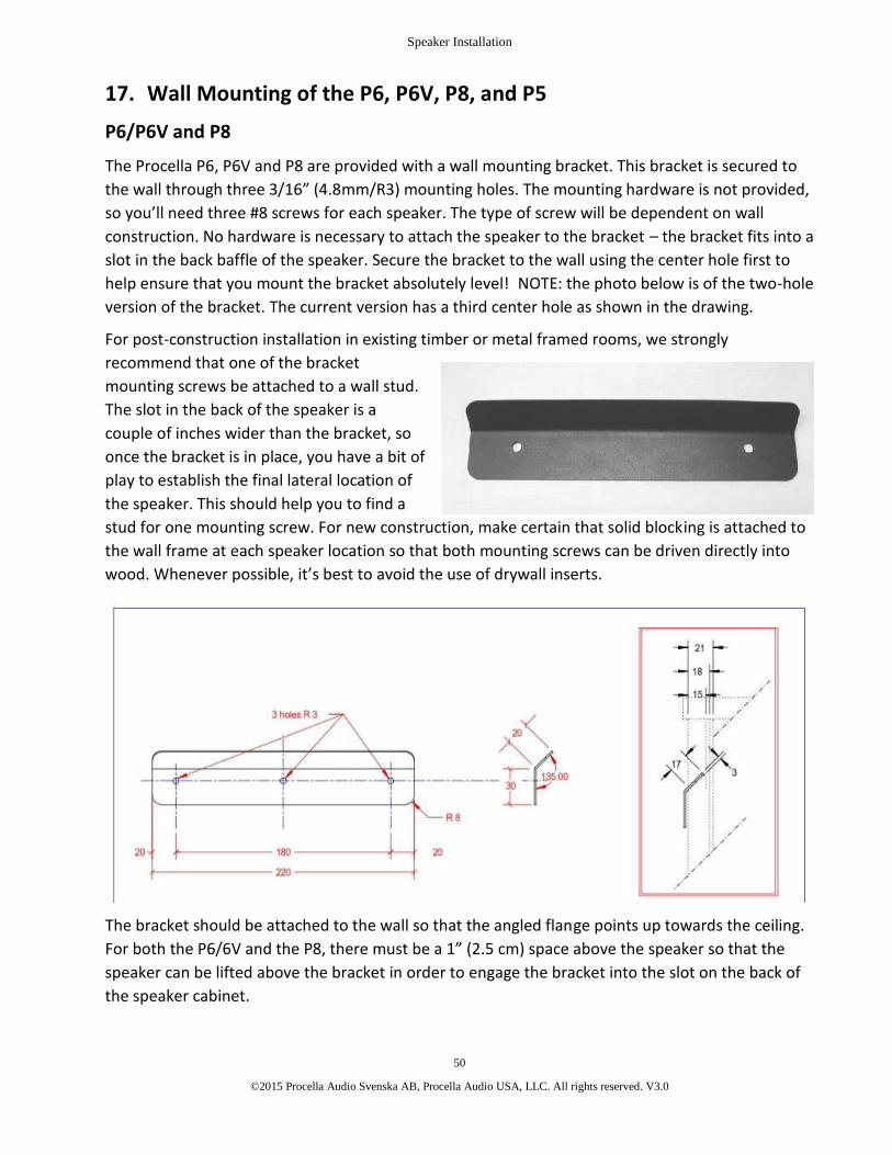
Speaker Installation
50
©2015 Procella Audio Svenska AB, Procella Audio USA, LLC. All rights reserved. V3.0
17. Wall Mounting of the P6, P6V, P8, and P5
P6/P6V and P8
The Procella P6, P6V and P8 are provided with a wall mounting bracket. This bracket is secured tothe wall through three 3/16” (4.8mm/R3) mounting holes. The mounting hardware is not provided,so you’ll need three #8 screws for each speaker. The type of screw will be dependent on wallconstruction. No hardware is necessary to attach the speaker to the bracket – the bracket fits into aslot in the back baffle of the speaker. Secure the bracket to the wall using the center hole first tohelp ensure that you mount the bracket absolutely level! NOTE: the photo below is of the two-holeversion of the bracket. The current version has a third center hole as shown in the drawing.
For post-construction installation in existing timber or metal framed rooms, we stronglyrecommend that one of the bracketmounting screws be attached to a wall stud.The slot in the back of the speaker is acouple of inches wider than the bracket, soonce the bracket is in place, you have a bit ofplay to establish the final lateral location ofthe speaker. This should help you to find astud for one mounting screw. For new construction, make certain that solid blocking is attached tothe wall frame at each speaker location so that both mounting screws can be driven directly intowood. Whenever possible, it’s best to avoid the use of drywall inserts.
The bracket should be attached to the wall so that the angled flange points up towards the ceiling.For both the P6/6V and the P8, there must be a 1” (2.5 cm) space above the speaker so that thespeaker can be lifted above the bracket in order to engage the bracket into the slot on the back ofthe speaker cabinet.

Speaker Installation
51
©2015 Procella Audio Svenska AB, Procella Audio USA, LLC. All rights reserved. V3.0
Before attaching the speaker to the bracket, attach the four provided silicone damping spacers tothe speaker. One should be mounted on each corner of the back baffle. These spacers reduceunwanted vibration transmission and provide spacing for the speaker cable.
The cable outlet in the wall behind the speaker should be located within the area of the recessedconnector cup on the back of the speaker. The cup is in the same relative location on both the P6and the P8 – centered 4” (100mm) from the left edge and 3” (75mm) from the top edge of thespeaker cabinet. The P6V cup is centered from left to right and 3.1” (80mm) from the bottom edgeof the speaker cabinet. The Product Tech Sheets in Appendix A detail the location of both themounting slot and the connector cup for all models.
To attach the speaker, simply lower the speaker so that the flange engages the slot in the back ofthe speaker. Make sure that the flange is fully engaged in the slot and that the bottom of thespeaker is in contact with the wall surface, and that there is no risk that the loudspeaker can bepushed from below up and off the bracket. If there is any doubt, take additional steps to secure thespeaker so it cannot be pushed upwards.
For the P6, the center line of the bracket holes is 55mm (2.17”) below the acoustical center of theloudspeaker (bottom edge of the waveguide).
For the P6V, the center line of the bracket holes is 15mm (.59”) above the acoustical center of theloudspeaker (bottom edge of the waveguide).
For the P8, the center line of the bracket holes is 15mm (.59”) above the acoustical center of theloudspeaker (bottom edge of the waveguide).
Allow for a variation of up to 3mm on these dimensions due to variation in the screws used and theactual bracket mounting.
When mounting the P6 or the P8 behind an acoustically transparent screen, the acoustical center(bottom edge of the waveguide) should be at a height 5/8 of the distance from the bottom of thescreen to the top of the screen.
P5 Wall Mounting
The back baffle of the P5 has two integral keyhole mounts. One is provided for horizontalmounting of the speaker and the other is provided for vertical mounting of the speaker. One ofthese will be used to hang the speaker on a single mounting screw.
A stud mount is always preferred, but when necessary a wall insert can be used as long as it iscapable of handling the 10 lb./4.5 Kg weight of the P5.
Before attaching the speaker to the bracket, attach the four provided silicone damping spacers tothe speaker. One should be mounted on each corner of the back baffle. These spacers reduceunwanted vibration transmission and provide spacing for the speaker cable.

Speaker Installation
52
©2015 Procella Audio Svenska AB, Procella Audio USA, LLC. All rights reserved. V3.0
The cable outlet in the wall behind the speaker should be located within the area of the recessedconnector cup on the back of the speaker. See the adjacent drawing or the P5 Tech Sheet inAppendix A for the exact location of mounting slot and the connector cup.
The recessed part of the cup is 70mm (2.76”) wide andlocated 45mm (1.77”) from the left side of the backbaffle and 55mm (2.17”) from the right side of the backbaffle. For vertical (tall) mounting, the mounting screwlocation is the center of the cabinet, 53mm (2.09”) fromthe top of the cabinet. For horizontal (wide) mounting,the mounting screw location is 144mm (5.67”) from theleft side of the cabinet (woofer side) and 38mm (1.5”)from the top of the cabinet.
To attach the speaker, simply lower the speaker so thatthe mounting screw engages the slot in the back of thespeaker. Make sure that the screw is fully engaged inthe slot and that the bottom of the speaker is in contactwith the wall surface, and that there is no risk that theloudspeaker can be pushed from below up and off thebracket. If there is any doubt, take additional steps tosecure the speaker so it cannot be pushed upwards.
For mounting with an adjustable bracket, werecommend the B-Tech BT33 bracket (www.btechavmounts.com). If you have difficulty finding thisbracket, please contact us. This bracket can be used for both wall and ceiling mounts. For wallmounting, the bracket attaches to the appropriate keyhole mount on the back of the speaker. Forceiling mounts, use one screw attached to the keyhole and a second screw into the back baffle ofthe speaker.
When mounting the P5 behind an acoustically transparent screen, the acoustical center (bottomedge of the waveguide) should be at a height 5/8 of the distance from the bottom of the screen tothe top of the screen.

Amplifiers, Connections and Calibration
53
©2015 Procella Audio Svenska AB, Procella Audio USA, LLC. All rights reserved. V3.0
18. Procella DSP and Amplifier Controls: P815, P10, P12, P15, P18All Procella active loudspeakers have built-in DSP control to optimize performance, based onspeaker placement in the room.
Any loudspeaker’s response at mid to low frequencies will be affected by its proximity to roomsurfaces. Generally, as a speaker is moved closer a room surface such as a wall, ceiling or the floor,the total low frequency energy produced by that speaker increases. This takes place due toacoustical coupling effects and reinforcement by the room’s surfaces. Because the location of aspeaker in any given room cannot be predicted, Procella’s DSP control tunes the response of thespeaker for optimal performance under several room boundary conditions. These products haveDSP control:
Subwoofers Main Speaker
P18 P815P15P10P12
The P10, P15, P18 and P815 have the same amplifier interface, which is described below. The P12uses a different amplifier platform with a different set of controls. See page xx for P12 amplifierinformation.
Operation (P10, P15, P18, P815)
Located on the control panel of each amplifier is abutton labeled Preset Select. Adjacent to thebutton are four green LEDs, each labeled with anumber that identifies a preset. Preset 4 is at thetop and Preset 1 is at the bottom of the stack.
To change the preset, press the Preset Selectbutton located between the XLR jacks. Each pressof the button advances to the next numberedpreset. The active preset is identified by anilluminated LED.
NOTE: These presets are for the onboardamplifiers only. They do not apply to the DA-2800DSP power amplifier.

Amplifiers, Connections and Calibration
54
©2015 Procella Audio Svenska AB, Procella Audio USA, LLC. All rights reserved. V3.0
P18, P15 and P10 Subwoofers
The presets for the P10, P15 and P18 subwoofers have identical functions, although the actual DSPis tuned for the actual performance of each subwoofer. This chart lists each preset and theinstallation condition for which each should be used. Each press of the button advances to the nextpreset.
Preset P18, P15 and P10 Installation Condition
4 Free standing on the floor and away from all walls and corners.
3 Flush mounted in a loudspeaker baffle wall, where the front surface of thesubwoofer should be flush with the surface of the baffle wall.
2 Positioned on the floor and against any wall (front, side, or back).
1 Positioned on the floor and in a corner.
Amplifier Level Control
The Gain control on the amplifier level sets the subwoofer level. The Default setting of “0” isequivalent to –4 dB, and is at the 12 o’clock position. The Default position should be used whencalibrating the system. The minimum – ∞ position produces no output from the subwoofer, andthe maximum position is 6 dB greater than the Default “0” position.
P815 Main Speaker
The P815’s DSP controls are also used to properly tune the speaker for the boundary conditions ofits installed location. As with the subwoofers, each press of the button advances to the next preset.
Preset P815 Installation Condition
4 Mounted in a baffle wall, behind a Stewart Filmscreen Microperf screen. This presetprovides compensation for the high-frequency losses of the screen.
3 Mounted in a baffle wall, behind an acoustically transparent screen or when noscreen is present. Use this preset when the speaker is flush against the front wall.
2 Free standing, away from walls in a large room. The speaker should be greater than4 feet from the wall. This position provides a +3 dB bass lift.
1 Free standing, away from walls in a small or medium size room. The speaker shouldbe greater than 4 feet from the wall. This position does not have any bass lift.
Amplifier Level Control
The Gain control on the amplifier level sets the level of the P815. The Default setting of “0” isequivalent to –4 dB, and is at the 12 o’clock position. The Default position should be used when

Amplifiers, Connections and Calibration
55
©2015 Procella Audio Svenska AB, Procella Audio USA, LLC. All rights reserved. V3.0
calibrating the system. The minimum position produces no output from the speaker, and themaximum position is 6 dB greater than the Default “0” position.
Amplifier Temperature (all AMP models)
It is normal for Procella amplifiers to be rather warm to the touch, even when the amplifier isoperating at low power levels. The very high power P815 and P18 amplifiers have low-noiseinternal cooling fans, and it is normal for these fans to operate. They will start at 60°C and willswitch off and on as needed. For all models, there is a warning LED that will blink if the ampreaches 80°C.
P12 Subwoofer Operation
The P12 uses a different amplifier than the P18, P15, and P10-AMP subwoofers. Its amplifier islocated on a recessed panel on the back baffle of the subwoofer. This allows for input and powercable attachment even with the subwoofer set flush against the wall.
Either unbalanced RCA or balanced XLR input cables can be used with the P12. When it is used witha preamp or processor with an unbalanced output, we recommend that a shielded 2-wire cablewith XLR connectors be used in combination with an RCA-XLR adapter at the preamplifier end. Thiswill produce the lowest noise level and best sound quality. An unbalanced RCA output connector isprovided for linking to additional P12 subwoofers.
The Procella P12 is designed for use with a 4th order Linkwitz-Riley, low pass crossover at 80-125Hz. The proper frequency depends on the main speakers used and the desired playback levels.With the Procella P5, use 120 Hz. For the Procella P6/P6V, Procella P8, and larger speakers, the‘THX’ setting in the processor (if available) will give the correct characteristics at 80Hz.
Rear Panel Controls and Functions
The P12 controls and their functions are described below. See the drawing on page 56 for locations.
Gain
The Gain control sets the subwoofer output level. For reference, the default 0 dB reference is -4dB.When setting subwoofer levels through a preamp or processor, the Gain control should be set to 0.
Polarity or Phase
The Polarity switch is used to match the polarity of the Procella P12 to the L-C-R speakers at thelistening position. This is important because of variables in the system such as the pre-amplifier,crossover slopes and, especially, room position of both the main speakers and the subwoofer.

Amplifiers, Connections and Calibration
56
©2015 Procella Audio Svenska AB, Procella Audio USA, LLC. All rights reserved. V3.0
Without test equipment, you can perform a simple test that requires a listener seated at the mainlistening position and a partner located at the subwoofer. Select and play through the full system amusic source with prominent mid-bass content. As it plays, the partner should flip the Polarityswitch when instructed to by the listener. The listener should listen carefully for changes in themid-bass level. The switch position that produces the greatest bass output is the correct setting.
Speaker Position
Optimizes response for room boundaryconditions at the location of the subwoofer. Usethe appropriate preset for the location in yourroom.
WALL Positioned on the floor and againsta wall.
CORNER Positioned on the floor, againsta wall and close to a corner.
Power
ON Subwoofer fully ON.
AUTO Standby model. Subwoofer switcheson when signal is present. TheSTANDBY LED illuminates when inSTANDBY mode.
SET See Auto Setup below.
POWER There is also a Master Power switchlocated on the input panel below.
Auto Setup
When selected, AUTO powers up the subwoofer only when a signal is present. Because it detectsthe residual noise level of the preamp/processor, the circuit needs to be calibrated before use.
Once the input cable is connected between the subwoofer and the preamp/processor, do thefollowing. Set the power switch on the preamp/processor to ON (or out of Standby), with no sourceplaying. Then, on the subwoofer, move the switch to Set. The P12 STANDBY LED will start blinkingrapidly. When the LED blinking rate slows down, move the switch to AUTO.
You can confirm that you have the correct setting by playing any disc and verifying that theSTANDBY LED switches to Green when the material starts playing. If the LED turns green withoutany source playing, check your installation and cable routing for AC mains or signal interference.

Amplifiers, Connections and Calibration
57
©2015 Procella Audio Svenska AB, Procella Audio USA, LLC. All rights reserved. V3.0
19. Procella DA-2800 2,800 Watt Four-Channel Power AmplifierThe Procella DA-2800 2,800 Watt Four-Channel Power Amplifier is a highly versatile very high-performance professional amplifier designed to optimize the performance of any Procella Audiospeaker system. It is highly recommended for any Procella installation, and can be used with anyProcella model, including all subwoofers.
There are three versions of the amplifier:
The DA-2800 DSP provides selectable DSP EQ presets for the P815, P18, P15, P10 and P10Si, as wellas active DSP crossover settings for the P815 and P610.
The DA-2800 DSP / P860 is specially programmed for use with the P860. One amplifier is requiredfor each loudspeaker.
The DA-2800 non-DSP version is available for system applications and individual channels that donot require DSP.
Additional detailed information on the DA-2800 is provided in the DA-2800 User Guide. Please referto this document when installing the amplifier.
DA-2800 as an Outboard Amplifier with the P815, P18, P15 and P10
The DA-2800 DSP enables users to have outboard amplification for the P815, P18, P15 and P10. Insystems where it is desirable to place the amplifiers in the rack, or to avoid having amplifiersbehind a screen or wall, this is a highly useful option. The P815-FP, P18-FP, P15-FP and P10-FPspeakers are designed to be used with the DA-2800 DSP. They are identical to the standardversions of the speakers except for the fact they have no onboard amplifier. These speakers can bespecial ordered from Procella or an authorized distributor. For configuration information, see theDA-2800 User Guide.
DA-2800 DSP Speaker & Subwoofer Amplifier Channel RequirementsNote: when two amplifier channels are bridged, one amplifier input is linked to both channels.
P5 1 amplifier channelP6/6V/6iW 1 amplifier channelP8 1 amplifier channelP610 2 amplifier channels (1 ch. LF, 1 ch. Mid/HF) with DSP preset for biamplificationP815 3 amplifier channels (1 bridged pair LF, 1 ch. Mid/HF) and DSP preset for biampingP860 4 amplifier channels (3 ch. LF, 1 ch. Mid/HF) and DSP presets for biamplificationP10Si 1 amplifier channel and DSP preset requiredP10 1 amplifier channel and DSP preset requiredP15 1 amplifier channel and DSP preset requiredP18 4 amplifier channels (2 bridged pairs) and DSP preset required

Amplifiers, Connections and Calibration
58
©2015 Procella Audio Svenska AB, Procella Audio USA, LLC. All rights reserved. V3.0
Procella Loudspeaker Programming (DA-2800 DSP only)
Located on the back panel of the DA-2800 are twobuttons labeled PRESET, each with four adjacent LEDindicators. The layout is shown at left. These PRESETsettings are used to configure the amplifier for theloudspeakers with which it will be used.
Each time a button is pressed, it advances the DSPsetting to the next preset. The active preset is indicatedby the illuminated LED. The right Preset button (Preset 1)controls Channels 1 and 2, and the left Preset (Preset 2)button controls Channels 3 and 4.
Each of these presets is pre-programmed with DSPsettings customized for Procella loudspeakers. The standard DA-2800 DSP has presets to covervirtually all applications using Procella loudspeakers. The P860 requires a custom version of theDA-2800 DSP , which should be ordered along with the loudspeakers. If a unique customconfiguration is required, please contact Procella Audio to place a special order. Please contactyour Procella dealer or distributor for more information.
The charts on the next page show the standard DA-2800DSP Preset configurations with the correctsettings for each speaker model. In some cases, such as with the P815-FP, one or two amplifierchannels are available to drive either speakers (P6/6V/6iW or P8), or subwoofers (P10 and P15).These additional options are shown on the charts.
DA-2800 DSP Speaker Configurations and DSP Presets
CAUTION: Use these presets ONLY with the specific speakers designated in the charts below. Useof the wrong preset can cause high levels of distortion and result in speaker damage that is notcovered by warranty. These instructions apply only to the DA-2800DSP.
For the P860, a specially programmed DA-2800DSP must be used. Contact Procella for details.
On the charts:
PRESET identifies which numbered PRESET on the back panel of the amplifier should be selected.PRESET 1 is on the right (Ch.1/Ch.2) and PRESET 2 is on the left (Ch.3/Ch.4).
LINK shows the correct setting for the LINK switch on the back panel of the amplifier, and if the Linkcable is needed, which Inputs it should connect.
INPUT identifies the correct input to be used and which inputs are not used.
OUTPUT identifies which output should be connected to each speaker.
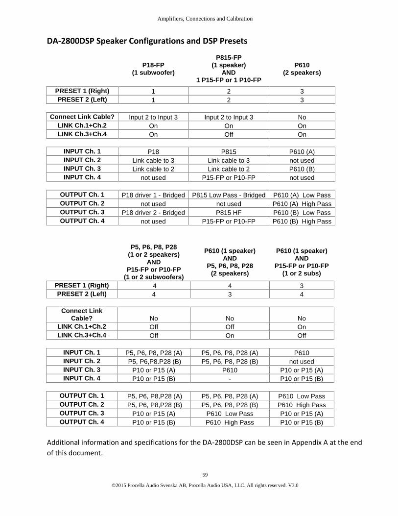
Amplifiers, Connections and Calibration
59
©2015 Procella Audio Svenska AB, Procella Audio USA, LLC. All rights reserved. V3.0
DA-2800DSP Speaker Configurations and DSP Presets
P18-FP(1 subwoofer)
P815-FP(1 speaker)
AND1 P15-FP or 1 P10-FP
P610(2 speakers)
PRESET 1 (Right) 1 2 3PRESET 2 (Left) 1 2 3
Connect Link Cable? Input 2 to Input 3 Input 2 to Input 3 NoLINK Ch.1+Ch.2 On On OnLINK Ch.3+Ch.4 On Off On
INPUT Ch. 1 P18 P815 P610 (A)INPUT Ch. 2 Link cable to 3 Link cable to 3 not usedINPUT Ch. 3 Link cable to 2 Link cable to 2 P610 (B)INPUT Ch. 4 not used P15-FP or P10-FP not used
OUTPUT Ch. 1 P18 driver 1 - Bridged P815 Low Pass - Bridged P610 (A) Low PassOUTPUT Ch. 2 not used not used P610 (A) High PassOUTPUT Ch. 3 P18 driver 2 - Bridged P815 HF P610 (B) Low PassOUTPUT Ch. 4 not used P15-FP or P10-FP P610 (B) High Pass
P5, P6, P8, P28(1 or 2 speakers)
ANDP15-FP or P10-FP
(1 or 2 subwoofers)
P610 (1 speaker)AND
P5, P6, P8, P28(2 speakers)
P610 (1 speaker)AND
P15-FP or P10-FP(1 or 2 subs)
PRESET 1 (Right) 4 4 3PRESET 2 (Left) 4 3 4
Connect LinkCable? No No No
LINK Ch.1+Ch.2 Off Off OnLINK Ch.3+Ch.4 Off On Off
INPUT Ch. 1 P5, P6, P8, P28 (A) P5, P6, P8, P28 (A) P610INPUT Ch. 2 P5, P6,P8.P28 (B) P5, P6, P8, P28 (B) not usedINPUT Ch. 3 P10 or P15 (A) P610 P10 or P15 (A)INPUT Ch. 4 P10 or P15 (B) - P10 or P15 (B)
OUTPUT Ch. 1 P5, P6, P8,P28 (A) P5, P6, P8, P28 (A) P610 Low PassOUTPUT Ch. 2 P5, P6, P8,P28 (B) P5, P6, P8, P28 (B) P610 High PassOUTPUT Ch. 3 P10 or P15 (A) P610 Low Pass P10 or P15 (A)OUTPUT Ch. 4 P10 or P15 (B) P610 High Pass P10 or P15 (B)
Additional information and specifications for the DA-2800DSP can be seen in Appendix A at the endof this document.

Amplifiers, Connections and Calibration
60
©2015 Procella Audio Svenska AB, Procella Audio USA, LLC. All rights reserved. V3.0
20. Cables and Connectors
Speaker Wire Connection
The following are our recommended minimums for loudspeaker cable used with Procellaloudspeakers. Feel free to use premium speaker cables per your preference, but we do not haveany specific recommendations for cable brands.
Cable run up to 25m (80’) AWG 14 (2.5mm²)
Cable run of 25 to 45m (80 – 150’) AWG 12 (4mm²)
Cable run of 45 to 75m (150-250’) AWG 10 (6mm²)
If you are planning to connect more than one surround speaker to a single amplifier channel with aparallel connection, we recommend that separate speaker wires be run from each speaker to theamplifier. This will provide maximum flexibility.
Active Speaker Connection
All active speakers with onboard amplifiers (P815, P18, P15, P12, P10) use balanced XLR inputs. TheP12 also provides unbalanced RCA inputs. All except the P12 have one male and one female XLRconnector to allow for a pass-through connection to another speaker. We strongly recommend theuse of balanced cables with Procella speakers because they produce minimum system noise andmaximum signal quality. When only unbalanced connections are possible, such as with A/Vreceivers, an RCA to XLR adaptor is provided with each active speaker.
Also see Section 21 on page 61 for connection to components with unbalanced outputs.
XLR Connector Wiring
Pin 1 = Ground
Pin 2 = Normal Polarity (Hot)
Pin 3 = Inverted Polarity (Cold)
Polarity
All Procella speakers have positive polarity. The red terminal is the positive (+) input, and a positivevoltage applied to it will produce a forward motion of the drivers.

Amplifiers, Connections and Calibration
61
©2015 Procella Audio Svenska AB, Procella Audio USA, LLC. All rights reserved. V3.0
21. AC and Grounding Requirements and TroubleshootingThe amplifiers in all Procella active speakers have universal power supplies that will operate to specwith any input voltage from 100V to 250V AC. The standard IEC three-prong connection is used forthe AC power cord.
All Procella amplifiers are High-Power, Switched-mode Class-D amplifiers. Like any digital amplifier,proper mains, grounding and signal interconnections are essential for correct operation, to avoidhum and buzz and to achieve the best possible signal to noise ratio.
Always follow these guidelines:
· Insure that the amplifier is connected to a properly grounded electrical outlet. A good and stableground connection is essential for correct operation of the switch-mode amplifier and the DSP.
· A proper ground connection is also essential to avoid electrical shock hazard.
· Procella Active Loudspeaker models utilize very high power amplifiers. Confirm that the powerline and circuits are dimensioned to handle the necessary load according to these guidelines:
Model: Recommended Minimum Load Rating
P10 115V: 10A 230V: 6A
P12 115V: 10A 230V: 6A
P15 115V: 10A 230V: 6A
P18 115V: 20A 230V: 10A
P815 115V: 20A 230V: 10A
· The power line should be free from disturbances caused by other electrical appliances such asmotors, heaters and ovens, elevators, refrigerators or similar.
· All Procella active loudspeaker amplifiers have a professional balanced (XLR Female) input. For thebest possible performance, it is strongly recommended that the amplifier be connected with aprofessional XLR-type, shielded 2-wire cable to a balanced output of the pre-amplifier.
· If the amplifier is connected to a pre-amplifier orprocessor with an unbalanced output, use a n RCA-to-XLRadaptor wired according to IEC 268-12 where pin 2 issignal and pins 1 and 3 are connected to the shell. (e.g.Neutrik NA2NMP) The adaptor should be connected at thepre-amplifier end and the cable to the amplifier should bea professional XLR-type, shielded 2-wire cable.

Amplifiers, Connections and Calibration
62
©2015 Procella Audio Svenska AB, Procella Audio USA, LLC. All rights reserved. V3.0
To minimize ground-loops in an unbalanced connection, connect the Procella active loudspeakeramplifiers to the same outlet as the pre-amplifier or processor and run the signal cable in parallelwith the mains cable.
If hum or buzz is present in the system, despite following the above precautions, below are somesteps to solve the most common issues:
Confirm that all cables and connectors are in good shape and that there are no badconnections.
If it is not possible to connect the Procella active loudspeaker amplifiers to the same walloutlet as the pre-amplifier, try different wall outlets for the amplifier, preferably to an outleton a different circuit.
Modify the unbalanced to balanced adaptor (or make a separate adaptor) with a 10-100ohmresistor in series with pin 1.
If nothing else helps, use a balancing isolation transformer such as:
o Lundahl Transformers model LL156X-PHF3MX
o Jensen Transformers model ISO-MAX SUB-XX

Amplifiers, Connections and Calibration
63
©2015 Procella Audio Svenska AB, Procella Audio USA, LLC. All rights reserved. V3.0
22. Bass Management and Surround Processor SettingsThe P6/6V/6iW and P8 are designed for use with a Procella subwoofer, and should be fed with asignal high-pass filtered by a surround processor or electronic crossover. The recommendedcrossover for both models is 80 Hz, and the correct slope is a second-order (12 dB/octave) Linkwitz-Riley filter. The P5 should use a crossover frequency of 120 Hz for High Power application, alsowith a second-order Linkwitz-Riley filter. This is the same crossover used for Home THX processorsor receivers, so if you are using a THX component, set the crossovers to the THX setting. If there isno THX choice, use the SMALL speaker setting. Do not use the LARGE setting with the P6/6V/6iWand the P8, as this will prevent low frequencies from being directed to the subwoofer. There is nolow-pass filter in Procella active subwoofers, so the low-pass filter slope of the subwoofercrossover should be fourth-order (24 dB/octave).
The P860, P815 and P610 are full-range speakers, with low-frequency extension to 40 - 45 Hz.Because of this deeper bass extension, they should be operated as full-range speakers (as inprofessional cinemas and dubbing stages). If necessary, they should only be used with a subwoofercrossover frequency of 40 – 45 Hz or higher. Ideally, the P815 and P610 should be set as FULL-RANGE (LARGE) speakers in the processor, with the subwoofer set to a low-pass frequency at 50 Hzor below.
For calibration of subwoofer levels, the level control on the subwoofer should first be set to theDefault position, which is labeled as “0” and is at the 12 o’clock position on the control. Thisrepresents a level of –4 dB. Final levels can then be set using the controller or preamplifier. Theminimum position on the subwoofer level control produces no output from the subwoofer, and themaximum position is 6 dB greater than the Default “0” position.

Technical Specifications and Dimensions
64
©2015 Procella Audio Svenska AB, Procella Audio USA, LLC. All rights reserved. V3.0
23. Appendix A – Product Specifications and Dimensional Information
Procella Product Line-Up 66
DA-2800 Technical Specifications 67
P5 Dimensions 69
P5 Technical Specifications 70
P6 Dimensions 71
P6 Technical Specifications 72
P6V Dimensions 73
P6V Technical Specifications 74
P6iW Dimensions 75
P6iW Technical Specifications 76
P8 Dimensions 77
P8 Technical Specifications 78
P28 Dimensions 79
P28 Technical Specifications 80
P610 Dimensions 81
P610 Technical Specifications 82
P815 Dimensions 83
P815 Technical Specifications 84
P860 Dimensions 85
P860 Technical Specifications 86
P10 Dimensions 87
P10 Technical Specifications 88
P12 Dimensions 89
P12 Technical Specifications 90
P15 Dimensions 91
P15 Technical Specifications 92
P18 Dimensions 93
P18 Technical Specifications 94
Technical Specifications and Dimensions
65
©2015 Procella Audio Svenska AB, Procella Audio USA, LLC. All rights reserved. V3.0
P10Si Dimensions 95
P10Si Technical Specifications 96
P8 and P6/P6V Speaker Mounting Bracket Dimensions 97
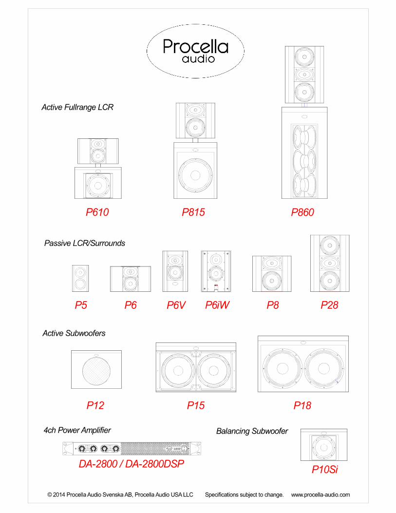

2,800W Four-Channel Power Amplifier
Technical Specifications
DA-2800/DA-2800DSP
• 360W x 4 channels at 8 ohms
• 700W x 4 channels at 4 ohms
• Bridgeable to 1,400W x 2 channels at 8 ohms
• Two versions: DA-2800 amplifier only
DA-2800 DSP with DSP and Ethernet
• DSP Version: selectable EQ presets optimized
for P860, P815, P18, P15, P10, P10Si
• DSP Version: preset crossovers for outboard
biamplification of the P860, P815 and P610
• DSP Version: Ethernet control interface
• Outboard amp option for P815, P18, P15, P10
Procella Audio USA • (310) 572-1070 • Fax (509) 561-3223 • [email protected] • www.procella-audio.com
DA2800 v1.2 2012.10
Defining the standard in amplification for Procella
loudspeakers and subwoofers, the DA-2800 gives
users a powerful platform to enable uncompromised
performance with any Procella Audio speaker system.
This high-efficiency class-D amplifier has extraordinary
sound quality with enormous power reserves. As you
would fully expect from Procella, the DA-2800’s sound
quality is utterly transparent, with an extremely wide
dynamic range and robust low-frequency impact.
Four channels of amplification deliver a solid 360W
each at 8 ohms, or 700W each at 4 ohms, with the
additional ability to produce 1,400W at 8 ohms when
two channels are bridged (highly recommended for
the P18!). Two versions are available: the DA-2800 is a
basic power amplifier, and the DA-2800DSP adds DSP
control (and Ethernet) to ensure optimal performance
with any Procella loudspeaker.
In channel pairs, users have the choice of four DSP EQ
presets to either optimize the response of individual
Procella subwoofers or to provide DSP crossovers for
the P860, P815 and P610.
Users can choose from standard EQ preset configura-
tions, or, on a custom order basis, specify any combi-
nation of presets. The non-DSP DA-2800 can be used
where DSP is not required (e.g., P6 and P8).
Multiple speakers and/or subwoofers can be driven by
a single DA-2800, depending on system requirements.
The amplifier can be used in place of the onboard
amp usually found on the P815, P18, P15 and P10 -
simply order the speaker(s) without the integral amp.
See Specifications for each model’s amplifier require-
ments and options.
In a 1U rack mount height, the compact DA-2800
packs a robust output capability in a very efficient
space, and it weighs just over 16 pounds.
For the ultimate Procella experience, the DA-2800 is
the only amplifier choice!
• Fully protected against DC, thermal overload
and short circuits
• Four year warranty
• Neutrik® XLR balanced inputs and Speakon®
speaker wire output connectors
• Recessed front panel level controls and
LED indicators
• CE and CSA certified
• High efficiency Green Audio Power™ design
• Switchable 115V/230V power supply
• Compact and lightweight -
1 RU high and only 7.4 Kg (16.3 lbs.)

Number of Channels Four
Power Output (per channel, 4 channels)8 ohms 360 Watts4 ohms 700 Watts
Bridged Power Output (2 channels bridged)8 ohms 1,400 Watts
Inputs Balanced Neutrik XLRfemale connectors (4)
Outputs Neutrik Speakon NL4MDconnectors (4)
Frequency Response 10 Hz - 30 KHz (+/-3dB),for 1W @ 8 ohms
Signal to Noise >113 dBA 20-20KHz,A weighted
THD+N < 0.05% from 0.1W to fullpower (<.01% typical)
SMPTE IMD < 0.05% from 0.1W to fullpower (<.01 typical)
DIM100 IMD <0.02% from 0.1W to fullpower (<.005 typical)
Max. Output Voltage 85V peak
Max. Output Current 60A peak
Slew Rate 40V/msecond,input filter bypassed
Damping Factor > 500 @ 100 Hz
Crosstalk <70 dB @ 1 KHz
Input Impedance 10 Kohms, balanced
Input Sensitivity 1.34V / 4.76 dBu
Gain 32 dB
Certifications CE and CSA certified
Front Panel IndicatorsInput LEDs: 3 green (signal, -18dB, -6dB)(each channel) 1 red (clip)
Ready/Temp. LEDs: 1 white (ready)1 yellow (thermal protection on)
Cooling Variable speed fan, temperaturecontrolled, airflow front to rear
Front Panel ControlsLevel One per channel, stepped
Power Rocker On/Off switch
Back Panel ControlsInput Link Feeds one input to two channels
(Ch.1 + Ch.2 or Ch.3 + Ch.4)
DSP and Ethernet DSP Version only (see below)
Power Supply 115V / 230V, internallyselectable; IEC connector
Idle Power 60W (.53A @230V, 1.1A @115V)
Dimensions 1.75” x 19” x 14.1”HxWxD 44.5 x 483 x 358mm
Shipping Carton 3.5” x 22” x 18.1”HxWxD 90 x 560 x 460mm
Net Weight 16.3 lbs. / 7.4 Kg
Shipping Weight 19.6 lbs. / 8.9 Kg
DA-2800 DSP Version
DSP Presets Two banks of four selectable pre-(back panel) programmed presets with LEDs;Bank 1: Ch.1 + Ch. 2Bank 2: Ch. 3 + Ch. 4
Ethernet RJ45 connector,(back panel) rotary address switches
Network Presets can be managed anduploaded over network
Delay up to 10 ms for each channel
DA-2800/DA-2800DSP SPECIFICATIONS
Procella Speaker & Subwoofer Amplifier Channel RequirementsNote: when two amplifier channels are bridged, one amplifier input is linked to both channels
P6 and P8 1 amplifier channelP610 2 amplifier channels (1 ch. LF, 1 ch. Mid/HF) and DSP required for biamplificationP815 3 amplifier channels (1 bridged pair LF, 1 ch. Mid/HF) and DSP required for biamplificationP860 4 amplifier channels (3 ch. LF, 1 ch. Mid/HF) and DSP required for biamplificationP10Si 1 amplifier channel and DSP requiredP10 and P15 1 amplifier channel and DSP requiredP18 4 amplifier channels (2 bridged pairs) and DSP required

���
�����
���
��� ���
�
� ����
�������
���
����
������
��
������
�����
�����
���
� �
!�"
�#
�$���
� �%�%�
������
&�'(�
)*+
�
��
,��
-�.��
����
�����
/���
����
�0
���
1�����
�����
��/���
�����2
2+
������
3���
$���%��
��
�/�4�
�%�%���
5� ��*������6
66*3
����
�����
/���
*���
���
���
�7�3��1�%%��
�����
��8
!
!��
%��9�
�8
!1��
�0��:
5�%�
����
���
�%%��3
��
%:
���
5%�;
!����
�����
*2
1�<�
���/
���;
�*�
2���0
�����.--<�
.-<�
��
�
��-
�=-
�-.
�9
=
�-
.
�..
�9
=
�
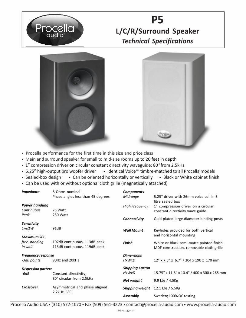
Impedance 8 Ohms nominal
Phase angles less than 45 degrees
Power handling
Continuous 75 Watt
Peak 250 Watt
Sensitivity
1m/1W 91dB
Maximum SPL
free-standing 107dB continuous, 113dB peak
in wall 113dB continuous, 119dB peak
Frequency response
-3dB points 90Hz and 20kHz
Dispersion pattern
-6dB Constant directivity;
80° circular from 2.5kHz
Crossover Asymmetrical and phase aligned
2.2kHz, BSC
L/C/R/Surround Speaker
Technical Specifications
Components
Midrange 5.25” driver with 26mm voice coil in 5
litre sealed box
High Frequency 1” compression driver on a circular
constant directivity wave guide
Connectivity Gold plated large diameter binding posts
Wall Mount Keyholes provided for both vertical
and horizontal mounting
Finish White or Black semi-matte painted finish.
MDF construction, removable cloth grille
Dimensions
HxWxD 12” x 7.5” x 6.7” / 304 x 190 x 170 mm
Shipping Carton
HxWxD 15.75” x 11.8” x 10.4" / 400 x 300 x 265 mm
Net weight 9.9 Lbs / 4.5Kg
Shipping weight 12.1 Lbs / 5.5Kg
Assembly Sweden; 100% QC testing
Procella Audio USA • (310) 572-1070 • Fax (509) 561-3223 • [email protected] • www.procella-audio.com
P5
P5 v1.1 2014.11
• Procella performance for the first time in this size and price class
• Main and surround speaker for small to mid-size rooms up to 20 feet in depth
• 1” compression driver on circular constant directivity waveguide: 80° from 2.5kHz
• 5.25” high-output pro woofer driver • Identical Voice™ timbre-matched to all Procella models
• Sealed-box design • Can be oriented horizontally or vertically • Black or White cabinet finish
• Can be used with or without optional cloth grille (magnetically attached)

�����������
�� �����������������
�������������������������
����
� ����������� !"#�$������%�%��� ���
�&�'%�����(��
��������)�
�*�����)�+�
),������-���
��
���%�$���.��������%�
����/���$� ��
.��%01*��������
�
2� 3����
����*���
���������
��4����4���
)��������
����*���
5�*������ ������������/���3���2���� ���������������66(
�7� �$� �%��������8� %�%�� 0�����������999�7�� ����������� ��
�*�����)�+�
2�$$���9���� �%���%�1�����'�44������+�,��'��*���
.���0%���1�+��3��!�*�6��
� ���%� ��
(��%��
*+��������)�
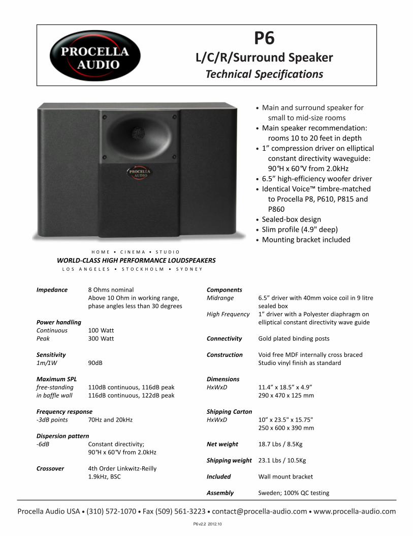
Impedance 8 Ohms nominal
Above 10 Ohm in working range,
phase angles less than 30 degrees
Power handling
Continuous 100 Watt
Peak 300 Watt
Sensitivity
1m/1W 90dB
Maximum SPL
free-standing 110dB continuous, 116dB peak
in baffle wall 116dB continuous, 122dB peak
Frequency response
-3dB points 70Hz and 20kHz
Dispersion pattern
-6dB Constant directivity;
90°H x 60°V from 2.0kHz
Crossover 4th Order Linkwitz-Reilly
1.9kHz, BSC
L/C/R/Surround Speaker
Technical Specifications
Components
Midrange 6.5” driver with 40mm voice coil in 9 litre
sealed box
High Frequency 1” driver with a Polyester diaphragm on
elliptical constant directivity wave guide
Connectivity Gold plated binding posts
Construction Void free MDF internally cross braced
Studio vinyl finish as standard
Dimensions
HxWxD 11.4” x 18.5” x 4.9”
290 x 470 x 125 mm
Shipping Carton
HxWxD 10” x 23.5" x 15.75"
250 x 600 x 390 mm
Net weight 18.7 Lbs / 8.5Kg
Shipping weight 23.1 Lbs / 10.5Kg
Included Wall mount bracket
Assembly Sweden; 100% QC testing
• Main and surround speaker for
small to mid-size rooms
• Main speaker recommendation:
rooms 10 to 20 feet in depth
• 1” compression driver on elliptical
constant directivity waveguide:
90°H x 60°V from 2.0kHz
• 6.5” high-efficiency woofer driver
• Identical Voice™ timbre-matched
to Procella P8, P610, P815 and
P860
• Sealed-box design
• Slim profile (4.9" deep)
• Mounting bracket included
WORLD-CLASS HIGH PERFORMANCE LOUDSPEAKERS
Procella Audio USA • (310) 572-1070 • Fax (509) 561-3223 • [email protected] • www.procella-audio.com
P6
P6 v2.2 2012.10

����������
���������
������� ��
�����������
�����������������������
������������������ ���!��
��"#�
$������#�����"%& �'!(������)�)�������
���*�+)�����,�"
��������
������� ��
����������
���
$��)�(���-���!��.�)�
����/���(����
-��)01��������
�
2��3����
44������4��
4��������
5����������������.����$/���3���2������������.�����$��66,
$7���(���)������.�8��)�)���0�����������999�7�������!�.�������
������� ��
2�((���9�����.)!�.)�1�����+�44����������+�����
-���0)��1����3��&���6��
���.�)����
,��)��
�������:��
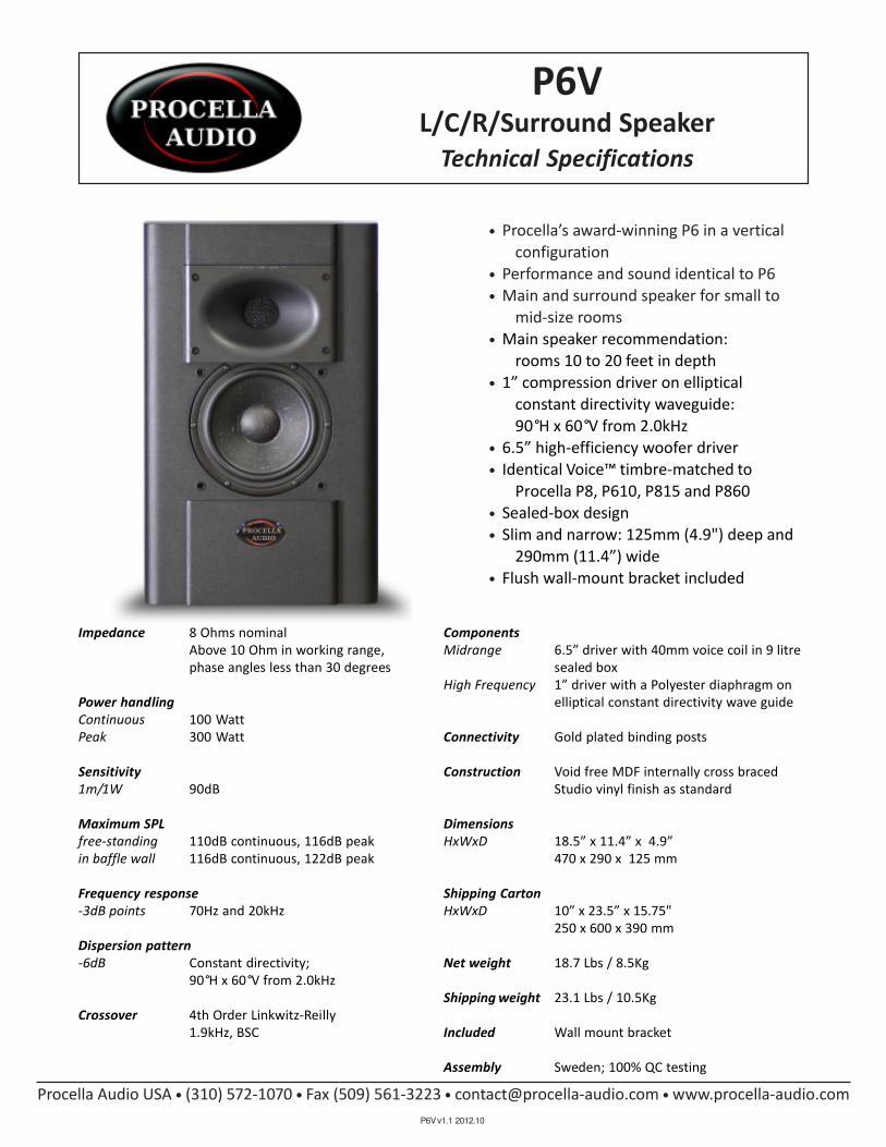
Impedance 8 Ohms nominal
Above 10 Ohm in working range,
phase angles less than 30 degrees
Power handling
Continuous 100 Watt
Peak 300 Watt
Sensitivity
1m/1W 90dB
Maximum SPL
free-standing 110dB continuous, 116dB peak
in baffle wall 116dB continuous, 122dB peak
Frequency response
-3dB points 70Hz and 20kHz
Dispersion pattern
-6dB Constant directivity;
90°H x 60°V from 2.0kHz
Crossover 4th Order Linkwitz-Reilly
1.9kHz, BSC
L/C/R/Surround Speaker
Technical Specifications
Components
Midrange 6.5” driver with 40mm voice coil in 9 litre
sealed box
High Frequency 1” driver with a Polyester diaphragm on
elliptical constant directivity wave guide
Connectivity Gold plated binding posts
Construction Void free MDF internally cross braced
Studio vinyl finish as standard
Dimensions
HxWxD 18.5” x 11.4” x 4.9”
470 x 290 x 125 mm
Shipping Carton
HxWxD 10” x 23.5” x 15.75"
250 x 600 x 390 mm
Net weight 18.7 Lbs / 8.5Kg
Shipping weight 23.1 Lbs / 10.5Kg
Included Wall mount bracket
Assembly Sweden; 100% QC testing
• Procella’s award-winning P6 in a vertical
configuration
• Performance and sound identical to P6
• Main and surround speaker for small to
mid-size rooms
• Main speaker recommendation:
rooms 10 to 20 feet in depth
• 1” compression driver on elliptical
constant directivity waveguide:
90°H x 60°V from 2.0kHz
• 6.5” high-efficiency woofer driver
• Identical Voice™ timbre-matched to
Procella P8, P610, P815 and P860
• Sealed-box design
• Slim and narrow: 125mm (4.9") deep and
290mm (11.4”) wide
• Flush wall-mount bracket included
Procella Audio USA • (310) 572-1070 • Fax (509) 561-3223 • [email protected] • www.procella-audio.com
P6V
P6V v1.1 2012.10

���
�����
�����
���
�����
�������
���
������
���
��
��
������
�����
������
����
� ��
!�"
�#
����
���$�$�
������
%�&
'( �
����
)��
�����
���
����
����
*��
��+�
��,
��
-�����
�����
� *��
��� �.
.(
����������
/��
���$�
���
�*�0�
�$�$���
1����'������&
&&'/
����
�����
*��
'��2
���
�3� 432
2%
����
�3� �332
2%
�3����5��2
2�6
�!
�����
�*$��*$�7��89
��'�
� �4�9:
��2
2%
���
1$�7�
-�9�
+��*
2��7
�3'�
.���,
�������9�
��9�
��2
2
6;<
����
�3 �
�2
2%
6 =��
���3
� :�2
2%
���
�3 :
�32
2%
�3��
��� :��2
2%
����
�3� ��32
2%
���
�3� ��2
2%
���
�3� 432
2%

In-Wall L/C/R/Surround/Height Speaker
Technical Information
• Identical performance and sound as
Procella’s award-winning P6
• All MDF sealed-box design including integral
back box
• Drivers and crossover mounted on removable
front baffle
• Main speaker for mid-size rooms; surround or
height channel for any size room
Procella Audio USA • (310) 572-1070 • [email protected] • www.procella-audio.com
P6iW
P6iW v1.0 2014.11
Impedance 8 Ohms nominal. Phase
angles less than 30 degrees.
Power handling
Continuous 100 Watt
Peak 300 Watt
Sensitivity
1m/1w 90dB
Maximum SPL 116dB continuous, 122dB peak
Frequency response
-3dB points 70 Hz and 20 kHz
Dispersion pattern
-6dB Constant directivity;
80° circular from 2.0kHz
Crossover 4th Order Linkwitz-Reilly.
1.9kHz, BSC
Connectivity Gold plated push terminals
Components
Midrange 6.5” driver with 40mm voice coil
in 9 litre sealed box
High Frequency 1” compression driver, circular
constant directivity waveguide
Construction Solid MDF, sealed back box.
Dimensions
Speaker WxH 12.875” x 18.5” / 328 x 470mm
Depth 3.9"/ 98mm (fits in standard U.S. walls)
Wall cut-out 11.5" x 17" / 292 x 432mm
Grille WxH 15.75” x 19.7” / 400 x 500mm
Shipping Carton
HxWxD 5.75” x 19.7" x 23.6"/ 265 x 500 x 600 mm
Net weight 22 Lbs. / 10 Kg
Shipping weight 26.5 Lbs. / 12 Kg
Optional Black steel grille, black fabric
Assembly Sweden; 100% QC testing
• 6.5” high-efficiency woofer driver
• 1” pro compression driver on 80° circular
constant directivity waveguide
• Ideal for ceiling mounted Atmos and
VOG 3D Audio height channels
• Elegant wing-shaped white grille with white
fabric cover adds attractive and distinctive
look to any environment; black grille optional

������
������
��
�� ��
����
�����
���
����
����
������
����
����
�� ��
� �
!�����
� "
#$%�
&��
%
����
'�()
�
"���
���
� �
������
���
�� �
��
*)�
�����
�*��+
���(%�
�(%�
*�,-
� '
&.
�&
(+�)%
�/����$
�)�
�"���
����
/*
.0�"���
��"
1��
����
0����
*.
2�3
*4
�����
�(���
�%��
���
��
"���
���
� 5
��
����
���
�5 �
�� �6
"��
���
� �
��
7�"
��"�*
)���
����&
+��
�1-�
(%!
��&
�8��*
)���
����&
+��
�/1
&�#
#'
19���
������(%�
%$:�
�����
��(�� ������
��
9)�
�����
��+��
���
1��
���
)��
����
��(�
%���-
���� ��
+�
�+�
"���
���
����
"���
���
� �
��
"��
���
� �
������
���
5 �
��
����
���
� �
��
�
����
���
� �
��

Impedance 8 Ohms nominal
Above 12 Ohms in working range,
phase angles less than 30 degrees
Power handling
Continuous 250 Watt
Peak 1,000 Watt
Sensitivity
1m/1W 92dB
Maximum SPL
free-standing 116dB continuous, 122dB peak
in baffle wall 122dB continuous, 128dB peak
Frequency response
-3dB points 80Hz and 20kHz
Dispersion pattern
-6dB Constant directivity;
80°H x 50°V from 1.5kHz
Crossover 4th Order Linkwitz-Reilly
1.6 KHz, BSC
Components
Midrange 8” high output driver with 40mm
voice coil in 15 litre sealed box
High Frequency 1.5” driver with a Polyester diaphragm on
elliptical constant directivity wave guide
Connectivity Gold plated binding posts
Construction Void free MDF internally cross braced
Studio vinyl finish as standard
Dimensions
HxWxD 16.125” x 17.7” x 7.875 / 5.4” (7° tilt)
410 x 450 x 200 / 138 mm (7° tilt)
Shipping Carton
HxWxD 19.75” x 23.5"x 12"
500 x 600 x 305 mm
Net weight 34.2 Lbs / 15.5 Kg
Shipping weight 37.7 Lbs / 17.1 Kg
Included Wall mount bracket
Assembly Sweden; 100% QC testing
• Main and surround speaker for mid to
large-size rooms
• Main speaker for rooms 15 to 30 feet deep
• THX Approved for integration into pro-
fessional rooms, including THX Certified
Screening Rooms and THX pm3 Studios
• 1.5” compression driver on elliptical
constant directivity waveguide:
80°H x 50°V from 1.5kHz
• High-output 8” woofer with 1.5” (40mm) VC
• Identical Voice™ timbre-matched to Procella
P860, P815, P610 and P6
• Back baffle angled at 7°
• Sealed-box design
• Shallow depth (7.9” deep)
• Mounting bracket included
Procella Audio USA • (310) 572-1070 • Fax (509) 561-3223 • [email protected] • www.procella-audio.com
L/C/R/Surround Speaker
Technical Specifications
P8
P8 v2.2 2012.10

���������������� ��������������������������
������ ��� ����!�"#$%�
&��%����
'�()�
*)�������*��
&(+�)%�,����$�)����-�����
,*./
*��0��0+���'&.
1������/����*.2-3*4������(����%�����
�
5������*)�������&+���16�(% ��&�7��*)�������&+���,1&�##'���18���������(%�%$9��������(�������������8)��������+������
������������
�������������
������������
"������������
!������������
���

Impedance 4 Ohms nominal
Above 6 Ohms in working range,
phase angles less than 30 degrees
Power handling
Continuous 500 Watt
Peak > 1,000 Watt
Sensitivity
1m/1W 95 dB
Maximum SPL
free-standing 122 dB continuous, 128 dB peak
in baffle wall 128 dB continuous, 132 dB peak
Frequency response
-3dB points 75 Hz and 20 kHz
Dispersion pattern
-6dB Constant directivity;
80°H x 35°V from 1.5kHz
Crossover 4th Order Linkwitz-Reilly
1.6 KHz, BSC
Components
Midrange 8” Neodymium magnet driver with 40mm
voice coil in 35 litre sealed box
High Frequency 1.5” driver with a Polyester diaphragm on
elliptical constant directivity wave guide
Connectivity Gold plated binding posts
Construction Void free MDF internally cross braced
Studio vinyl finish as standard
Dimensions
HxWxD 25.8” x 17.7” x 7.1
655 x 450 x 180 mm
Shipping Carton
HxWxD 31.5” x 23.6"x 11.8"
800 x 600 x 300 mm
Net weight 46.3 Lbs / 21.0 Kg
Shipping weight 49.6 Lbs / 22.5 Kg
Assembly Sweden; 100% QC testing
• Extremely high output main and surround
speaker for mid to large-size rooms
• 8 meter THX Cinema reference level
(105dB continuous) speaker
• Main speaker for rooms 15 to 50 feet deep
• Single-enclosure design with internal
crossover does not require
biamplification or DSP
• 1.5” compression driver on elliptical
constant directivity waveguide:
35°H x 50°V from 1.5kHz
• Dual custom high-output 8” woofers with
1.6” / 40mm voice coils
• Identical Voice™ timbre-matched to Procella
P860, P815, P610, P8 and P6
• 80Hz subwoofer crossover point
• Sealed-box design
• Shallow depth (7.1” / 180mm deep)
Procella Audio USA • (310) 572-1070 • Fax (509) 561-3223 • [email protected] • www.procella-audio.com
L/C/R/Surround Speaker
Technical Specifications
P28
P28 v1.0 2014.03

������
������
��
�� ��
����
�����
���
����
������
����
�� ��
���
��!
��"
��
#��
$
����
%�&'
�
('�
�����
�(�����
���
#$$
��
"�)
#&*�'$
�+����"
�'�
���,�
����
+(
-.��/,0
(����%
#-
1��
����
.����
(-
2,3
(4
�����
�&���
�$��
���
/���
���
�!�!
��
����
���
���
��
%�&�
'$&��
����
��
���5
���6
�&
!��
���
���
��
!��
���
���
��
����
���
���!
��
�!��
���
���/
��
����
���
!��
��
��*��'�
�$
1��
���
'��
����
��&�
$���7
�������
*�
�*�
����
���
����
����
$�*�
����
���
���
����
���
���
��
�/��
���
��/
��
����
���
!��
��
���
���
���
�
8��
���
�('�
�����
�#*��
�17�
&$�
��#
� ��(
'���
����#
*��
�+1
#�9
9%
1:���
������&$�
$";�
�����
��&����������
��
�:'�
�����
��*��
����
����
���
����
��

Biamplified L/C/R Speaker
Technical Specifications
P610
• High output main speaker for mid to large size
rooms 15 to 30 feet (5 to 9 meters) in depth
• Full-range operation with extension to 40 Hz
• Requires external active biamplification with DSP
crossover: Optimal performance with Procella
DA-2800DSP 2,800 Watt four-channel amplifier
• 1 inch compression driver on elliptical constant
directivity waveguide: 90°H x 60°V from 2.0 kHz
• 10 inch Pro-quality, Italian-made long-throw
woofer with 2.5” (65mm) voice coil
• High-efficiency 6.5 inch midrange with 1.5”
40mm voice coil
• Identical Voice™ timbre-matched to Procella P8,
P6, P815 and P860
• Very shallow depth (150mm / 5.9 inches deep)
• All sealed-box design for superior transient
response
Components
Low Frequency 10 inch long-throw driver with 65mm
(P10Si) voice coil in 18 litre sealed box
Midrange 6.5 inch driver with 40mm voice coil
(P6) in 9 litre sealed box
High Frequency 1 inch compression driver with a Polyester
(P6) diaphragm on a Procella-designed elliptical
constant directivity waveguide
Construction Void free MDF, internally cross-braced
Studio Black vinyl finish standard
Dimensions and Net Weight
HxWxD 27.6” x 21.3” x 5.9” / 51 lbs.
700 x 540 x 150 mm / 23 Kg
Shipping Cartons (2) and Weight
P6 (HxWxD) 10” x 23.5” x 15.75” / 23.1 lbs.
250 x 600 x 390 mm / 10.5 Kg
P10Si (HxWxD) 12” x 25” x 19.5” / 35.5 lbs.
305 x 635 x 500 mm / 16.1 Kg
Included Loudspeaker bracket, Damper feet
Assembly Sweden; 100% QC testing
Impedance 8 Ohms nominal
Power handling
Low Frequency 350 Watts continuous, 1,000 Watts
peak
High Frequency 100 Watts continuous, 300 Watts peak
Sensitivity
1m/1W 92 dB
Maximum SPL
free-standing 116dB continuous, 122dB peak
in baffle wall 122dB continuous, 128dB peak
Frequency response
-3dB points 40Hz and 20kHz
Dispersion pattern
-6dB Constant directivity:
90°H x 60°V from 2.0 kHz
Crossover 4th Order Linkwitz-Reilly
1.9 kHz (internal to P6)
150Hz (external DSP required)
Connectivity Two pair gold-plated binding posts
Procella Audio USA • (310) 572-1070 • Fax (509) 561-3223 • [email protected] • www.procella-audio.com
P610 v1.3 2012.10

������������������ �������������������������������������
������������������������������������������������� ���� ���� �������
����������������������������������������!��������������������� �������
"�#$%��������&�'$�����& �()�
���������������'$�����!�()�
*++##�,���)-������ ���,,��� )
.�#$%����#,)��#�,����
*��)#���
/�, �
���������&���
�!�������& ��
�������&���
���������&���
����0�����������&���
� ������������+#��,)#�,)�
����12�&/*3�
*,+� )�4$$��(� $��$����
4�30�!��5� ������5� !����� �
6������0�����3��7�8��#���,����)�����
����
���������& �� �������&!��
��0���������!&���
!������ �&!��
�9
�������&!��
�������&���
��9
������&���
�������������.� +�) �����
�:� �� �� �������*+#��62�,)'��*�5��� �������*+#��46*���/�
6-��#�#��#�,)�)(;������%�,$�����������&- ��������+#�&���

Procella Audio USA • (310) 572-1070 • Fax (509) 561-3223 • [email protected] • www.procella-audio.com
Biamplified L/C/R Speaker
Technical Specifications
P815
P815 v2.4 2012.10
• Main speaker for large to very large rooms, up
to small cinemas
• Recommended for rooms 25 to 50 feet in depth
• THX Approved for integration into professional
rooms, including THX Certified Screening Rooms
and THX pm3 Studios
• Active Biamplification: 700W+700W of high-
efficiency green class-D power
• 28 bit DSP for room placement conditions including
baffle wall and free standing
• P815-FP option enables use of Procella DA-2800DSP
2,800 Watt four-channel power amplifier
• 1.5” compression driver on elliptical constant
directivity waveguide: 80°H x 50°V from 1.5 kHz
• 8” high-output midrange with 2.5” voice coil
• 15” woofer with 3” voice coil
• Identical Voice™ timbre-matched to Procella P8,
P6, P610 and P860
• Sealed box design
• Shallow depth (14.2” / 360mm deep)
Active 700W + 700W of onboard power:
Biamplification 700W to P8 high frequency module
Standard P815 700W to LF815 low frequency module
P815-FP Enables external biamplification with
Option Procella DA-2800DSP 2,800 Watt
four-channel power amplifier
Maximum SPL
free-standing 122dB continuous, 126dB peak
in baffle wall 126dB continuous, 132dB peak
Frequency response
-3dB points 40Hz and 20kHz
Dispersion pattern
-6dB Constant directivity:
80°H x 50°V from 1.5kHz
Crossover 4th Order Linkwitz-Reilly
1.6 kHz and 150Hz
Components
Low (LF815) 15” driver with 75mm voice coil in 92
litre sealed box
Midrange 8” high output driver with 40mm
(P8) voice coil in 15 litre sealed box
High Frequency 1.5” driver with a Polyester diaphragm on
(P8) elliptical constant directivity waveguide
Connectivity Balanced XLR with provided RCA adaptor
Construction Void free and MDF internally cross braced
Studio vinyl finish as standard
Dimensions
HxWxD 43.7” x 19.7” x 14.2” / 1110 x 500 x 360 mm
Shipping Cartons (2) and Weight
P8 HxWxD 19.75” x 23.5"x 12" / 37.5 lbs.
500 x 585 x 305 mm / 17.0 Kg
LF815 HxWxD 25” x 32” x 25” / 115 lbs.
635 x 810 x 635mm / 52.0 Kg
Net weight 145 Lbs / 65.0 Kg
Included Connecting Bracket, Connecting cable,
Power cord, XLR-RCA adaptor, Damper feet
Assembly Sweden; 100% QC testing

���������������� ��������������������������
������ ����
��� ����
!�"#�
$#�������$�%�
� ��&�'
�"(�# �)����&�#���*+�����
)$,-��+�
$�%�.��.(��/!�,
0������-����$,1+2$3������"���� �����
�4������$#��������(���05�" 6����7��$#��������(���)0��88!
09���������" � &:��������"��/���������/9#��������(��/���
��������/��
;��������/���
��/�<
*��������/���
;%������*/���
��������/=��
�;�������/=��
��%�����%=/���
�*�������%/%��
��%�����*�/���
%��������/���

Impedance
Mid/HF 4 Ohms nominal
Low Frequency 3 inputs, each 4 Ohms nominal
Amplification Procella DA2800DSP power amplifier
Mid/HF 1 channel @ 700 Watts
Low Frequency 3 channels @ 700 Watts
Sensitivity
1m/1W 95 dB
Maximum SPL
free-standing 128dB continuous, 132dB peak
in baffle wall 132dB continuous, 138dB peak
Frequency response
-3dB points 40Hz and 20kHz
Dispersion pattern
-6dB Constant directivity:
80°H x 50°V from 1.0 kHz
Crossover 4th Order Linkwitz-Reilly
1.6 kHz and 150Hz
Components
Low Frequency Procella V6™: 6 x 10” drivers with 65mm
(V6) voice coils in 150 litre sealed box
Midrange 2 x 8” high output drivers with
(P28) 40mm voice coils in 30 litre sealed box
High Frequency 1.5” driver with a Polyester diaphragm on
(P28) elliptical constant directivity waveguide
Connectivity 3 LF, 1 HF inputs, gold-plated binding posts
Construction Void free MDF, internally cross-braced
Studio Black vinyl finish standard
Dimensions and Weight
HxWxD 69.5” x 20.9” x 14.2” / 201 lbs.
1765 x 530 x 360 mm / 90 Kg
Shipping Cartons (2) and Weight
P28 HxWxD 12” x 32” x 24” / 50 lbs.
305 x 810 x 610 mm / 22.5 Kg
V6 HxWxD 20” x 48” x 28” / 165 lbs.
510 x 1220 x 710 mm / 75 Kg
Included Loudspeaker bracket, Damper feet
Assembly Sweden; 100% QC testing
Biamplified High Output L/C/R Speaker
Technical Specifications
P860
• Very high output main speaker for the largest
domestic rooms up to and including mid-size
cinemas
• Recommended for rooms 12 to 24 metres in
length (40 to 80 feet)
• Stands a massive six feet tall
• Active biamplification with Procella DA-2800DSP
2,800 Watt four-channel power amplifier
• 1.5” compression driver on elliptical constant
directivity waveguide: 80°H x 50°V from 1.5 kHz
• Dual 8” high-output midranges
• V6™ Power: 6 x 10” woofers with 65mm voice coils
• Identical Voice™ timbre-matched to Procella P8
surround channel speakers
• Sealed box design
• Full-range operation with extension to 40 Hz
• Shallow depth (360mm / 14.2” deep)
P860 v1.3 2012.10
Procella Audio USA • (310) 572-1070 • Fax (509) 561-3223 • [email protected] • www.procella-audio.com

������������� �������
�������������������������
����
��������������� �!������"�"�������#
�$�%"$�� &'��
() ��*&+,#
* ��)&,#
���
� ��&+,#
-* ���-&*,#
.�������������������/���0���1���������������������22'
�3���!���"��������4��"�"���5����&�����666&3�������������&��
* ��)&,#
�+ ��&(,#
����"�������3���
!���������"���
� ��&+,#
7���5"��!�
�������!��"
1�!!���6������"���"����8�)��%�+ ���*&(,�%�,#
9���5"�8��(0�

Active DSP Subwoofer
Technical Specifications
P10
P10 v2.3 2012.10
Procella Audio USA • (310) 572-1070 • Fax (509) 561-3223 • [email protected] • www.procella-audio.com
• Dual-Drive Dual-Amp design
• Recommended for small to mid-size
rooms
• Twin 10” long-throw drivers with 2.5”
voice coils
• 350W+350W of high-efficiency green
Class-D amplification
• P10-FP option enables use of external
Procella DA-2800DSP 2,800 Watt
four-channel power amplifier
• Sealed-box design with heavily braced
cabinet
• Maximum output 119 dB @ 50Hz
• - 3 dB point 26 Hz
• Ultra-slim profile (7.1" / 180mm deep)
• 28-bit DSP control for room boundary
conditions:
- free standing
- against wall
- in corner
- in baffle wall
Frequency Response
-3 dB 26 Hz
Maximum SPL
@ 50 Hz 119 dB
Components Dual long-throw 10” drivers with
65mm voice coils in 36 litre sealed box
DSP Section 28 / 56 bit ADI Sigma
DSP Settings Free standing
User selectable Against wall
In corner
In baffle wall
Amplifier 350W + 350W, Class-D
Line Voltage 100 - 250V, 40 - 80 Hz
Connectivity Balanced XLR
RCA input adaptor provided
P10-FP Enables external amplification and
Option DSP with Procella DA-2800 2,800
Watt four-channel power amplifier
Construction Heavily internally braced MDF
Studio vinyl finish as standard
Dimensions
HxWxD 18.5” x 26.8” x 7.1”
470 x 680 x 180 mm
Shipping Carton 12.6” x 31.5"x 23.5" / 320 x 800 x 600 mm
Net weight 57.5 Lbs / 26.0 Kg
Shipping weight 66.5 Lbs / 30.1 Kg
Included Power cord, XLR-RCA adaptor,
Damper feet
Assembly Sweden; 100% QC testing
WORLD-CLASS HIGH PERFORMANCE LOUDSPEAKERS

�����������
�� �������������������
��������
���������
������� �!��"�#�$�%&�����'�'�������(
)�*�����+��,�� -
���.������� *� */
0� 1������������� &�������.���)�������������� &������--���2��&%&��'&�������3��'�'���4������������555�2���������� &����+
���
"���'��++�6�"
)��.��& �����++�6�"
)���.7�84&'��6�''��2�&�'
�/
11
����
����������� ��
�������������

Active 350 Watt Subwoofer
Technical Specifications
P12
P12 v1.1 2014.11
Procella Audio USA • (310) 572-1070 • Fax (509) 561-3223 • [email protected] • www.procella-audio.com
• 12” long-throw driver with
2.5 inch / 65 mm voice coil
• 350W of high-efficiency green Class-D
amplification
• Maximum output 116 dB @ 50Hz
• - 3 dB point 25 Hz
• Standby power ensures that sub is active
before program material starts by
calibrating to processor noise level
• Polarity Normal/Reversed switch
• Sealed-box design with heavily
braced MDF cabinet
• Ultra-slim profile (8.3” / 210mm deep)
• Recessed back-panel connectors enable
placement against wall
• Selectable EQ for room boundary conditions:
- Against wall
- In corner
Connectivity Single balanced XLR
Single RCA input, Single RCA output
Line Input 40 - 80 Hz, switchable 110 - 240V
Standby Programmable
Power Standby <0.5W
Consumption Full Power 440W
Safety Approval CE, FCC, CCC
Construction Heavily braced MDF
Finish White or Black matte painted finish,
steel grille
Included Rubber mounting feet
Dimensions
HxWxD 17.3” x 22.8” x 8.3” / 440 x 580 x 210 mm
Shipping Carton 20.5” x 27.6"x 11.8" / 520 x 700 x 300 mm
Net weight 35.2 Lbs / 16.0 Kg
Shipping weight 37.5 Lbs / 17.0 Kg
Frequency Response
-3 dB 25 Hz
Maximum SPL
@ 50 Hz 116 dB
Components Long-throw 12” driver with
65mm voice coil in 31 litre sealed box
Polarity Switchable Normal/Reversed
Room Settings Against wall
User selectable In corner
Amplifier 350W, Digital Class D

������������ ��������
�� ���� ��������������������������������� �!�
"�������� �#������� $�!
%&&����� ��'���
�(�������(�
)(��� ��)�*�&�������
%&�(��+��� $�(���������
� )�*,-���.%/
0�� ���1����)/234)5�� ����������� �!
���
6��� ������&�
���& ���
�*��������!
�������� �!
7� ���������!
������������!
���������8�!
*8�������� �!
�*������ �!
��
)(��� ��)�*�&�������
%&�(��+��� $�(���������
+)/1��*3�9���3����
)�*,-���.%/
0�� ���1����)/234)5�� ����������� �!
:������)(��� ��%�&���0-��#��%�9��)(��� ��%�&���+0%�;;.
0'�������������$<����������������������'(��� ����&������

Frequency Response
-3 dB 22 Hz
Maximum SPL
@ 50 Hz 125dB
Components Dual long-throw 15” drivers with
Neodymium magnets and 75mm voice
coils in 75 litre sealed box
DSP Section 28 / 56 bit ADI Sigma
DSP Settings Free standing
User selectable Against wall
In corner
In baffle wall
Amplifier 350W + 350W, Class-D
Line Voltage 100 - 250V, 40 - 80 Hz
Connectivity Balanced XLR
RCA input adaptor provided
P15-FP Enables external amplification with
Option Procella DA-2800DSP 2,800 Watt four-
channel power amplifier
Construction Heavily internally braced MDF
Studio vinyl finish as standard
Dimensions
HxWxD 22.4” x 36.6” x 8.7”
570 x 930 x 220 mm
Shipping Carton 14” x 41"x 27"
360 x 1045 x 685mm
Net weight 88 Lbs / 40.0 Kg
Shipping weight 100 Lbs / 45.0 Kg (plus pallet)
Included Power cord, XLR-RCA adaptor,
Damper feet
Assembly Sweden; 100% QC testing
• Dual-Drive Dual-Amp design
• Recommended for mid to large-size
rooms
• Twin 15” long-throw drivers with 3”
voice coils
• 350W+350W of high-efficiency green
Class-D amplification
• P15-FP option enables use of external
Procella DSP-2800DSP 2,800 Watt
four-channel power amplifier
• Sealed-box design with heavily braced
cabinet
• Maximum output 125 dB @ 50 Hz
• - 3 dB point 22 Hz
• Shallow depth (8.7” / 220mm deep)
• 28-bit DSP control for room boundary
conditions:
- free standing
- against wall
- in corner
- in baffle wall
Procella Audio USA • (310) 572-1070 • Fax (509) 561-3223 • [email protected] • www.procella-audio.com
Active DSP Subwoofer
Technical Specifications
P15
P15 v2.2 2012.10
WORLD-CLASS HIGH PERFORMANCE LOUDSPEAKERS

Heig
ht of in
sula
tion feet
Baffle
wall cu
t-out = 1
100 x
700m
m ( 43.3
" x
27.6
" )
Weig
ht = 9
7kg
(215Lbs)
Additi
onal s
pace
for co
nnect
ors
© P
RO
CELLA AU
DIO
2009
Pro
cella
P18 d
imensi
ons
P18_vu
e.C
AD
Anders
Uggelb
erg
aug -09
UPD
: 15/9
Sca
le 1
:10 (PD
F/J
PG
-file
not to
sca
le)
650m
m (25.6
")
1050m
m (41.3
")
Ventila
tion a
nd
"Handle
s"
360m
m (14.2
")
R 6
0m
m (2.4
")
15m
m (0.6
")
P18
11m
m (0.4
")
35m
m (1.4
")
360m
m (14.2
")

Procella Audio USA • (310) 572-1070 • Fax (509) 561-3223 • [email protected] • www.procella-audio.com
Active DSP Subwoofer
Technical Specifications
P18
P18 v1.2 2012.10
• Dual-Drive Dual-Amp design
• Extremely high output for the largest
home cinemas, screening rooms
and small cinemas
• THX Approved for integration into
professional rooms, including THX
Certified Screening Rooms and THX
pm3 Studios
• Twin 18” long-throw drivers with 4”
voice coils
• 700W+700W of high-efficiency green
Class-D amplification
• P18-FP option enables use of external
Procella DA-2800DSP 2,800 Watt
four-channel power amplifier
• Critically reinforced sealed-box design
• Maximum output 133 dB @ 50 Hz
• - 3 dB point 18 Hz
• Shallow depth (360mm / 14.2”)
• 28-bit DSP control for room boundary
conditions:
- free standing - against wall
- in corner - in baffle wall
Frequency Response
-3 dB 18 Hz
Maximum SPL
@ 50 Hz 133dB
Components Dual long-throw 18” drivers with
100mm voice coils in 205 litre
sealed box
DSP Section 28 / 56 bit ADI Sigma
DSP Settings Free standing
User selectable Against wall
In corner
In baffle wall
Amplifier 700W + 700W, Class-D
Line Voltage 100 - 250V, 40 - 80 Hz
Connectivity Balanced XLR
RCA input adaptor provided
P18-FP Enables external amplification and
Option DSP with Procella DA-2800 2,800 Watt
power amplifier
Construction Heavily internally braced MDF
Studio vinyl finish as standard
Dimensions
HxWxD 25.6” x 41.3” x 14.2”
650 x 1050 x 360 mm
Shipping Carton 25” x 48"x 32"
635 x 1220 x 815 mm
Net weight 220.5 Lbs / 100.0 Kg
Shipping weight 254 Lbs / 115.0 Kg (plus pallet)
Included Power cord, XLR-RCA adaptor,
Damper feet
Assembly Sweden; 100% QC testing
WORLD-CLASS HIGH PERFORMANCE LOUDSPEAKERS

���������������� ����������������������������
������ ���������� !"
#$�������#��%�
&���'"��'"
(')�$"�*����!�$�����+����
*#&,�
#��"�-��-)��./(&
%������,����#&0�1#2������'����"�����
���������.���
/�''���$�3�'���
��')�'��3�"
/�'�$"'�������
����4���5�'
6�������#$�������()���%7�'"���(����#$�������()���*%(� /
%3���������'"�"!8��������'�������������.3$��������)��.���
�����
���������.���
��������.9��

Balancing Subwoofer
Technical Specifications
P10Si
Construction Void free MDF, internally cross-braced
Studio Black vinyl finish standard
Dimensions
HxWxD 14.37” x 21.3” x 5.9”
(horizontal) 365 x 540 x 150 mm
Shipping Carton
HxWxD 12.6” x 31.5” x 23.5”
300 x 800 x 600 mm
Net Weight 30.8 lbs. / 14 Kg
Shipping Weight 35.5 lbs / 16.1 Kg
Included Damper feet
Assembly Sweden; 100% QC testing
Impedance 8 Ohms nominal
Power handling
Continuous 350 Watts
Peak: 1,000 Watts
Sensitivity
1m/1W 92 dB
Maximum SPL
@ 50 Hz 113 dB
Frequency response
-3dB 26Hz
Components 10 inch long-throw driver with 65mm
voice coil in 18 litre sealed box
Connectivity Gold-plated binding posts
• Designed for use in multiple room
locations to smooth low frequency
room modes
• Optimizes low-frequency response
when used with P18, P15 or P10
main subwoofers
• 10” Pro-quality Italian-made long-throw
subwoofer driver with 2.5” voice coil
• Reqires external amplification with
DSP crossover: Optimal performance
with Procella DA-2800DSP 2,800 Watt
four-channel power amplifier
• Sealed-box design with heavily braced
cabinet for superior transient
response
• Maximum output 113 dB @ 50Hz
• In-room -3 dB point 26 Hz
• Ultra-slim profile (5.9"/150mm deep)
• Fits in standard wall framing
U.S. - 14 3/8”, vertical orientation
EU - 540mm, horizontal orientation
The P10Si provides integrators with a highly useful new
option that facilitates the use of multiple subwoofers to
produce more consistent bass performance in listening
rooms. When one or more Procella P18, P15 or P10
subwoofers are used as main subwoofers, multiple P10Si
subwoofers can be placed in different room locations to
smooth the low frequency modes of the room. This can
improve the overall bass quality and significantly reduce
seat-to-seat variance in low frequency levels.
Procella Audio USA • (310) 572-1070 • Fax (509) 561-3223 • [email protected] • www.procella-audio.com
P10Si v1.3 2012.10

���������������� ����
�����
������
�
��
�
������
������
���
����
��
��
�
��
���
��� ��!
��� ����
���
�"
#���
�$�
%&
'(
���
�)�
��*
+�
((
,-.
��
��
!/
���
�0
!
!�
�!�-�
�
0�
��
���
��
12
0$�-�
��
��
��
3��
)#4
�5
����
)��6�
�
��
����
��
!
���