Embed Size (px)
Citation preview

PUMICE SYSTEM CHIMNEYS & LINERS
...naturally better
DOC/CP3/64 SAP Issue 6 940002642 February 2017 Part of the BRAAS MONIER BUILDING GROUP

2
Pumice - naturally better
Product Description
Pumice is a natural insulator. This is the unique property that separates pumice from all other chimney materials.
The insulating properties of Pumice allow the flue gases in the chimney to quickly reach their optimum temperature enabling the heating appliance to reach its optimum performance shortly after lighting.
It also keeps the chimney warmer longer as the heat output of the appliance decreases - once again aiding performance and reducing the likelihood of condensation and soot build-up.
Resistant to temperature changePumice has very little expansion and contraction with temperature change. This reduces the possibility of cracking and structural damage that can occur with other products.
High Insulation PropertiesPumice is a natural insulator, able to maintain the temperature of flue gases when other products have allowed the temperature to fall below the dew point.
LightweightPumice is strong yet lightweight allowing one person to lift and build the chimney units.
The natural properties of pumice
Pumice is a natural material sourced from the Hekla Volcano in Iceland.
Pumice is an excellent insulator,keeping flue gases warm while not transmitting heat to the outside.
Schiedel Isokern products can be used for new chimneys and for the refurbishment of existing chimneys. The Isokern chimney systems provide a lightweight, easily installed and versatile chimney which can be used internally or externally. The systems are suitable for use with burning appliances in new and refurbished projects. They are ideal for Masonry, Timber Frame and Steel Frame construction. Isokern chimneys have been installed in Europe for over 60 years.
DM (DOUBLE MODULE)Schiedel Isokern DM block system is a high quality System Chimney. The double wall system maintains flue gas temperatures while preventing heat transference to the outer casing. The separation of the inner and outer components also allows for thermal movement, reducing the risk of cracking and subsequent leaking or staining. It is simple and quick to build. The DM is available in 3 outer casing sizes - DM36, DM44 & DM54.
FLUE LINERSThe Schiedel Isokern flue liner range consists of over 15 different sizes. They can be used for newbuild, extensions and relining existing chimneys.
FIRECHESTSThe Schiedel Isokern range of firechests are supplied as flat packs. They can be easily and quickly constructed to produce a neat and pre-formed fire opening ready for finishing. The Magnum Firechest provides the opportunity to create fire openings up to 1.2m wide.
ISOKOAT FLUE SEALING SYSTEMThe Schiedel Isokoat system is an efficient and cost effective method of re-sealing a defective chimney shaft. The Isokoat material is applied to the chimney under pressure and forced into the cracks sealing them, re-pointing the joints and strengthening the walls. For further details see the separate Isokoat leaflet.

3
DM Double Module Chimney SystemWhen the ease of construction and maximum insulation matter then the Double Module System comes into its own. The system is designed to be quick and easy to install.
The lightweight blocks are easy to handle. The outer and inner blocks are laid at the same time but with staggered joints for safety and stability. The double layer of pumice blocks separated by an air gap maximises the chimney insulation.
The Pumice Systems are suitable for wood burning, solid fuel, oil and gas (not condensing appliances).
There are 3 systems covering a range of different internal diameters to meet the requirements of different appliances and uses:
DM 36 150mm internal diameter for smaller output inserts, stoves and solid fuel/oil cookers
DM 44180mm and 200mm internal diameters for inserts, stoves and open fires
DM 54300mm and 345mm internal diameters for Magnum firechests and larger appliances, inserts and open fires
Unique features of the Isokern DM Chimney System
Zero distance to combustibles on straight rendered chimneys
Quick and easy to assemble
Lightweight materials, easy to handle
Highly insulating pumice for better draw and minimum heat loss
Staggered joints for maximum safety and stability
Air gaps between outer casing and flue prevents surface staining
Good resistance to temperature variations gives the maximum performance for your appliance
Approvals
CE Designation
Double Module DM System Chimney*T450 N1 D 3 G(00)
Pumice Chimney LinerT450 N2 D 3 G
Isokern Pumice Double Module DM is CE Certified to EN1858 TÜV Cert no. 0036 CPR 90219 001 Isokern Pumice Chimney Liner is CE certified to EN1857 TÜV Cert no. 0036 CPR 90219 002 Isokern Magnum Firechest has been tested at the Fraunhofer Institut, Stuttgart, Cert no. P8-094/2006
* Zero distance to combustibles on straight chimney systems with ventilated terminal. 38mm distance to combustibles on offset systems. and non ventilated systems.

4
DM 36 - for smaller output inserts, stoves and cookersAvailable in Ø150mm internal diameter only.
Downloadable drawings available from our web site
www.schiedel.co.uk
Glass fronted inset fire
Capping for renderedchimney stack
Casings renderedabove roof
Lead flashing
All joints sealedwith lip glue
DM casings can befinished with plaster
Top Ring
Raincap
Support block and adaptor for connection to flue pipe
INSET FIRE
FREE STANDING STOVE IN A RECESS.System includes a Stainless Steel adaptor for ease of connection between the stove and the DM Chimney.
Chimney pot
Capping for brick chimney stack
Corbel forbrick stack
Flue blocks installedwith socket uppermost
Staggered joints between casing and flue block
Support block and adaptor for connection to stove pipe
Outer casings dry lined or plastered
Lead tray and flashing
Weep holes above tray
Sand/cement flaunching
FREE STANDING STOVE WITH EXTERNAL CHIMNEY AND PREFORMED FLUE ENTRY KIT
Top Ring
Raincap
Capping for rendered chimney stack
2 x casing ties at maximum intervals of 1.5 metres
Flue pipe fitted intoaccess casing at 45˚
Casing rendered above roof
Lead flashing

5
DM 36 -for smaller output inserts, stoves and cookers D
M 36
SAP Code Description Weight (kg)
All dimensions are external unless otherwise stated
130714 360mm square casing 250mm high 15
130713 360mm square casing & soot door 250mm high 18
130709 DM36 45º flue entry kit (four parts) 500mm high 42
126363 150mm i/d 255 x 255 starter flue block 125mm high 4
126369 150mm i/d 255x255 flue block 250mm high 8
126368 150mm i/d 255x255 access flue block 500mm high 16 (177mm i/d access hole)
130715 570mm square corbel for brickwork 75mm high 32
126378 150mm i/d 360 x 435 offset block (86mm, 30 ̊offset) 150mm high 25 (allow 38mm distance to combustibles on offset chimneys)
126373 150mm i/d (205mm o/d) stainless steel adaptor
130716 150mm i/d 360 square support block 100mm high 15
126357 125-150mm i/d (205mm o/d) stainless steel decreaser adaptor
135070 Top Ring (for ventilation)
130732 Raincap (with fixing rods for top ring)
130710 490mm square capping - render 13130711 690mm square capping - brickwork 31
130712 360mm square access casing 250mm high 13 (150mm i/d access hole)

6
DM 44 - for inserts, stoves and small open firesAvailable in internal diameters Ø180mm and Ø200mm.Both inner liners fit into the same external block size.
Downloadable drawings available from our web site
www.schiedel.co.uk
Chimney pot
Weep holesabove tray
INSET FIRE
Capping for brickchimney stack
Sand/cement flaunching
Lead tray and flashing
Corbel for brick chimney stack
Inner flue blocks withsocket uppermost
Support block and adaptor for connection to flue pipe
Glass fronted inset fire
Staggered joints between casing and flue block
38mm clearancefrom structural timber
Outer casings dry lined or plastered
OPEN FIRE USINGSTANDARD FIRECHEST
Lip glue to seal joints
40115 corbel to complete brick stack
Inner flue blocks withsocket uppermost
Staggered joints between casing and flue block
DM44 casings built into inner leaf of cavity wall
DM44 gather
Suitable foundation
Standard firechest(finished fireplace opening size ≤ 590 x 550mm)
Capping for brickchimney stack
Top Ring
Raincap

7
DM 44 - for inserts, stoves and small open fires D
M 44
SAP Code Description Weight (kg)
All dimensions are external unless otherwise stated
130727 440mm square casing 300mm high 30
130726 440mm square casing & soot door 300mm high 36
130719 440mm 180mm i/d 45˚ flue pipe entry kit (4 parts) 600mm high 86130722 440mm 200mm i/d 45˚ flue pipe entry kit (4 parts) 600mm high 84
130720 180mm i/d 310 x 310 starter flue block 150mm high 8127684 200mm i/d 310 x 310 starter flue block 150mm high 7
127068 180mm i/d 310 x 310 flue block 300mm high 15127683 200mm i/d 310 x 310 flue block 300mm high 14
130717 180mm i/d flue 310 x 310 access block 600mm high 28127682 200mm i/d flue 310 x 310 access block 600mm high 26
130728 650mm square corbel for brickwork 75mm high 40130235 650 x 560mm offset corbel for brickwork 75mm high 34
130818 740mm T corbel for external brickwork 75mm high 47
130723 570mm square capping for render 18130724 820mm square capping for brickwork 44
127691 200mm i/d (255mm o/d) stainless steel adaptor
127671 150-200mm i/d (255mm o/d) stainless steel decreaser adaptor127672 175-200mm i/d (255mm o/d) stainless steel decreaser adaptor
130721 180mm i/d 440mm square support block 100mm high 22130730 200mm i/d 440mm square support block 100mm high 20
131810 180mm i/d 440 x 500 offset block (56mm, 30 ̊offset) 100mm high 22130718 180mm i/d 440 x 500 offset block (86mm, 30 ̊offset) 150mm high 22127686 200mm i/d 440 x 500 offset block (56mm, 30 ̊offset) 100mm high 20127687 200mm i/d 440 x 500 offset block (86mm, 30 ̊offset) 150mm high 30 (Allow 38mm distance to combustibles on offset chimneys)
130725 440mm square access casing 300mm high 29 (220mm i/d access hole)
130732 Raincap (with fixing rods for top ring)
130675 Top Ring (for ventilation)

8
DM 54 - for larger open fires and appliancesAvailable in internal diameters Ø300mm and Ø345mm.Both inner liners fit into the same external block size.
Downloadable drawings available from our web site
www.schiedel.co.uk
LARGE FIRE OPENINGCREATED WITH MAGNUM FIRECHEST
Staggered joints between casing and flue block
Magnum firechestcomplete with damper
Fiirebrick lininginside firechest
DM casings can befinished with plaster
Joints sealed with lip glue
Casings renderedabove roof
Lead flashing
Capping for renderedchimney stack
Chimney pot

9
DM 54 - for larger open fires and appliances D
M 54
SAP Code Description Weight (kg)
All dimensions are external unless otherwise stated
130708 545mm square casing 300mm high 40
129043 300mm i/d 545mm square support block 100mm high 30
129031 300mm i/d 420 x 420 starter flue block 150mm high 11129093 345mm i/d 420 x 420 starter flue block 150mm high 11
129033 300mm i/d 420 x 420 flue block 300mm high 22129094 345mm i/d 420 x 420 flue block 300mm high 22
130735 800mm square corbel for brickwork 75mm high 57
130733 670mm square capping for render 20130734 950mm square capping for brickwork 46
129038 300mm i/d 545 x 635 offset block (86mm, 30 ̊offset) 150mm high 44129092 345mm i/d 545 x 635 offset block (86mm, 30 ̊offset) 150mm high 40 (allow 38mm distance to combustibles on offset chimneys)
AC
CESSO
RIES
DM AccessoriesSAP Code Description Weight (kg)
All dimensions are external unless otherwise stated
146432 1500 x 215 x 70mm support lintel Max load (per pair) 1650kg 51
130689 Stainless steel casing wall tie
102629 1m reinforcement rod 12mm diameter 1
130771 Lip glue (5kg) 5
129039 300mm i/d (365mm o/d) stainless steel adaptor
130732 Raincap (with fixing rods for top ring)
135093 Top Ring (for ventilation)

10
Typical DM Installation Detail
FOUNDATIONSConstruction begins by providing a suitable foundation and constructional hearth in accordance with Building Regulations and site requirements.
OPEN FIRE OPTIONBed the base plate of the firechest onto a suitable foundation/constructional hearth in accordance with Building Regulations and at the level required on site using Isokern lip glue.
Install the firechest using lip glue making sure all elements are level. 100mm of brick/blockwork must be built around the sides and back of the firechest to comply with Building Regulations. The inside of the firechest must be finished with a suitable fireback or firebrick slips.
Install the gather using lip glue making sure all the elements are level. The front face of the gather can be finished with plasterboard, rendered or clad in masonry. Lintels may be required above the gather to help carry the brick or blockwork. The maximum loading capacity of the ISOKERN firechest and gather is 2500kg.
TIMBER FRAME SOLUTIONFor timber framed solution refer to pages 21 - 22
STOVE IN RECESS OPTIONPre-stressed lintels or a suitable cast-in-situ concrete slab must be provided above the stove recess, please make sure they are strong enough to carry the load (see appropriate Isokern DM drawing for aperture size). It is recommended to have a minimum of 600mm of stove flue pipe before connecting to the support block.
The support block is bedded onto the lintels using a weak mix mortar. A stainless steel adaptor is used to create a positive connection from the support block to the stove flue pipe (fibre rope should be used to create a seal).
FREE STANDING STOVE OPTIONA soot door casing and access flue block must be used below the flue pipe entry. The DM 45˚ access kit is then used for the connecting flue pipe. A suitable wall sleeve must be used to seal the cavity wall. Any combustible insulation within the wall must then be kept away from the single wall connecting flue pipe by at least 1.5 x its diameter. Fibre rope is used to seal between the flue pipe and wall sleeve, a suitable trim collar can be used to finish the inner wall surface.
OPEN FIRE OPTION
Firebrick slips
Suitable foundation
Magnum firechest
Gather elements
STOVE IN RECESS OPTION
Support block
Lintels
Stainless steel adaptor
FREE STANDING STOVE OPTION
Flue entry kit
Wall sleeve andfibre rope seal
Prima flue pipe
Soot door casing
IGNIS-PROTECT 45˚ VERSION

11
Typical DM Installation Detail
CHIMNEY CONSTRUCTIONBed the first outer casing using lip glue making sure the rebate (raised lip) is uppermost. The starter flue block is then put inside the casing bedded with lip glue. The socket on the starter flue block must be uppermost and the air gap between the starter flue and the casing should be kept clear. The finished lip glue joints should be 2-3mm thick, a special bag is provided for ease of application and the lip glue should be applied in 12-15 mm beads.
Offset blocks ‘if required’ must be used immediately above the support block or firechest gather. (They cannot be used higher up the chimney.) They must be glued together with lip glue and be fully supported. Please note a chimney should be built straight wherever possible. A starter flue block will be required above the offset blocks to stagger the joints between the outer casing and inner flue blocks.
Casings and flue blocks are added using lip glue for all joints. Ensure the air gap between the inner flue and outer casing remains clear. The outer surface of the casings to be finished with plasterboard on dabs or plaster. The side that faces the wall does not need an external finish.
On a rendered stack with a top ring fitted (see p.12 for example), where a straight chimney passes through a floor or roof, zero mm distance to combustibles can be applied. A sliding joint is made using mineral wool or similar non-combustible material. In all other cases, 38mm clearance must be maintained between the outer face of the chimney and any structural timber or loose combustible material. Floor boards, skirting boards, dado rails and other non-structural components may, however, be in contact with the chimney.
External chimneys must be tied to the structure at maximum intervals of 1.5m and at the point where it departs from the roof using 2 x suitable stainless steel wall ties. These are fitted into the outer casing joints. They are not always required for internal chimneys. Please consult the Isokern technical office.
High tensile steel reinforcement rods will be required for all chimneys with a height that exceeds 1.4m above the roof line, 1.1m if the wind speed exceeds 44ms. These rods are available from Isokern and must be grouted (1:3 cement/sand) into the holes provided in the outer casings. You must start the rods at least the same height below the roof as what’s above, please check with our technical department.
HOW TO USE LIP GLUE
Reinforcement rods
Load bearing support
Starter flue block
Offset blocks mustbe fully supportedand bedded withlip glue
Plasterboard
DM outer casing
Stainless steel ties
DM outer casings
Inner flue blocks
Void to be kept clear
38mm clearance fromstructural timber
Non combustible material
Lip glue
Lip glue

12
Typical DM Installation Detail
RENDERED STACK OPTIONCode 4 lead flashing to be fitted at roof level as per Building Regulations. We recommend that you scorch a 5-10mm deep channel into the outer surface of the casings and fold in the top edge of the flashing.
Finish the outer surface of the casings above the roof with 2 part waterproof render. The recommended mix is 1:2:5-6 cement:lime:sand for the undercoats. 1:2:8-9 cement:lime:sand for the final coat. The number of coats required will depend upon the degree of exposure, generally a two coat mix is acceptable. The mix may vary due to climate conditions, the thickness of any one coat should not exceed 15mm, and each subsequent coat should be reduced by approximately 3mm.
Isokern concrete capping for render to be lip glued onto the last casing.
TERMINATIONRaincap - Ventilated Option - (Installation with 0 distance to combustibles for straight rendered chimneys only). Take the last flue block up through the capping, do not fill the gap between the flue block and capping. Push fit the aluminium top ring onto the flue block and make sure there is a 10mm air gap between the outer edge of the ring and the capping. The flue block may need cutting to suit.
Chimney Pot Option - This option always requires a 38mm distance to combustibles from the outside of the block. Fit a chimney pot at least 75mm down into the capping and flaunch with 1:3 cement and sharp sand to seal around. This option is not possible if 0 distance to combustibles is required.
AFTER COMPLETIONAfter installation is complete tests and checks should be carried out in accordance with document J of the Building Regulations. A chimney notice plate must be completed and permanently fixed in the dwelling, ideally near the electrical consumer unit. The checklist and notice plate are available from Schiedel Isokern.
USE AND MAINTENANCEThe chimney should be left for at least 72 hours before use, then start only with small fires for the first week and gently increase thereafter.
The chimney should be swept at least twice a year, once before the heating season and once after the heating season. You may need to sweep during the heating season depending upon use. The brush should be a medium density polypropylene bristle type and should be the same diameter as the flue. Steel brushes must not be used to sweep the Isokern pumice flues.
Always follow the appliance manufacturer’s operating instructions. Always burn approved fuels or dry seasoned wood. Avoid burning unseasoned wood and slow burning of solid fuels as this can produce excessive soot and condensation which in turn cause soot fires and damage. If correctly installed, operated and maintained these systems could last the life of the dwelling.
BRICK STACK OPTIONTo take brick or stonework externally a corbel is fitted just below the roof. Use trusses and trimmers to brace the cladding as it passes through the roof.
Code 4 lead tray with 50mm upstands and stepped flashing to be fitted in accordance with Building Regulations. A 50mm upstand should be fitted tight to the outside of the flue block and where possible turned in by approx 10mm. Lead trays should be coated with bituminous paint where it is in contact with mortar. The D.P.C. tray should be fitted at least 150mm above the lowest point of intersection with the roof. Weep holes should be provided at the front of the stack above the tray for water drainage.
Casings can be deleted above the corbel if stack height is less than 1.4m above the roof.
Code 4 lead flashing(not supplied)
Capping for render
Waterproof render
RENDERED STACK
10mm gap for ventilationunder Top Ring
BRICKWORK STACK
Corbel for brick stack
Lead tray and flashing Weep holes
above tray
Flue block or chimney pot

13
Liner System - for new and existing chimneysThe pumice liner system comes in a range of 15 diameters from 150mm to 1000mm with T Liners, Liner Support Blocks, and Adaptors for ease of connection to the appliance.
The insulated flue liner for traditional build
Lightweight materials, easy to handle
Highly insulating pumice for better draw and minimum heat loss
600mm and 1000mm lengths mean fewer joints and fast to install
15 flue sizes available
Good resistance to temperature variations gives the maximum performance for your appliance
Suitable for use with inserts, stoves, open fires and solid fuel/oil cookers.
INSET FIRE
Support block and adaptor for connection to flue pipe
Cast in situ slab tosupport chimney
Glass fronted inset fire
Downloadable drawings available from our web site
www.schiedel.co.ukFREE STANDING STOVE
Sand/cement flaunching around flue liner or chimney pot
Lead tray and flashing
Structural timber40mm from outsideof chimney or 200mmfrom inside of flue liner
Support block for stove connection
Support plate
7N blockwork
Joints sealed with lip glue
Standard flue liners with socket uppermost
Void filled with Leca insulation mix
140 x 140mm lintels
100 x 65mm lintels

14
Liners and AccessoriesLI
NER
S A
ND
AC
CES
SOR
IES SAP Code Description Weight (kg)
All dimensions are external unless otherwise stated
Round Liners126372 150mm i/d 600mm high rebated liner (200mm o/d) 8126498 175mm i/d 600mm high rebated liner (235mm o/d) 11127685 200mm i/d 600mm high rebated liner (250mm o/d) 12127715 225mm i/d 600mm high rebated liner (285mm o/d) 14128546 250mm i/d 600mm high rebated liner (310mm o/d) 16129036 300mm i/d 600mm high rebated liner (360mm o/d) 19129360 350mm i/d 600mm high rebated liner (416mm o/d) 27129567 400mm i/d 1000mm high rebated liner (470mm o/d) 50129738 450mm i/d 1000mm high rebated liner (530mm o/d) 60129927 500mm i/d 1000mm high rebated liner (590mm o/d) 70130142 600mm i/d 1000mm high rebated liner (706mm o/d) 100
Collars126361 150mm steel collar 126494 175mm steel collar127673 200mm steel collar127705 225mm steel collar128533 250mm steel collar129021 300mm steel collar129356 350mm steel collar
Liner Support Blocks (for connection to appliances)126366 150mm i/d 310mm square 75mm high 7126483 175mm i/d 350mm square 75mm high 8127340 200mm i/d 350mm square 75mm high 8130731 225mm i/d 440mm square 100mm high 20 128548 250mm i/d 440mm square 100mm high 20129043 300mm i/d 545mm square 100mm high 30
Leca 130769 50 litre Leca (0.05m3) approx. 19
Lip Glue 130771 Lip glue (5kg) 5
Support Lintel 146431 1500 x 140 x 140mm support lintels Max load (per pair) 3250kg 71
Support Plates (for supporting liners and support blocks)127694 210mm i/d 340mm square 4mm thick 3 (fits 150mm support blocks)128549 255mm i/d 360mm square 4mm thick 3 (fits 175mm and 200mm support blocks)
T Liners126376 150mm i/d 45˚ rebated T liner 600mm high 15126500 175mm i/d 45˚ rebated T liner 600mm high 20127695 200mm i/d 45˚ rebated T liner 600mm high 22126375 150mm i/d 90˚ rebated T liner 600mm high 15

15
LINER
S AN
D A
CC
ESSOR
IESLiners and Accessories
SAP Code Description Weight (kg)
All dimensions are external unless otherwise stated
Liner Bends126364 150mm i/d 15˚ rebated bend 4126365 150mm i/d 30˚ rebated bend 5126367 150mm i/d 45˚ rebated bend 6
Stainless Steel Adaptors with Sealing Rope (for connection to support block)126373 150mm i/d (205mm o/d)126499 175mm i/d (235mm o/d)127691 200mm i/d (255mm o/d)127719 225mm i/d (290mm o/d)128547 250mm i/d (315mm o/d)129039 300mm i/d (365mm o/d)
Stainless Steel Adaptors with Sealing Rope (for connection to T liners)125453 125-150mm i/d (210mm o/d)126358 150mm i/d (210mm o/d)146412 150-175mm i/d (240mm o/d)146413 175mm i/d (240mm o/d)
126495 175mm i/d 15˚ rebated bend 5126496 175mm i/d 30˚ rebated bend 6126497 175mm i/d 45˚ rebated bend 8
127679 200mm i/d 15˚ rebated bend 5127680 200mm i/d 30˚ rebated bend 6127681 200mm i/d 45˚ rebated bend 8
128542 250mm i/d 15˚ rebated bend 8128531 250mm i/d 30˚ rebated bend 9128532 250mm i/d 45˚ rebated bend 9
129354 350mm i/d 15˚ rebated bend 13129355 350mm i/d 30˚ rebated bend 14131820 350mm i/d 45˚ rebated bend 17
127706 225mm i/d 15˚ rebated bend 7127707 225mm i/d 30˚ rebated bend 8127708 225mm i/d 45˚ rebated bend 11
129015 300mm i/d 15˚ rebated bend 10129016 300mm i/d 30˚ rebated bend 11131819 300mm i/d 45˚ rebated bend 12
Stainless Steel Increaser Adaptors with Sealing Rope (for connection to support block)126357 125-150mm i/d (205mm o/d)126493 150-175mm i/d (235mm o/d)127671 150-200mm i/d (255mm o/d)127672 175-200mm i/d (255mm o/d)127704 200-225mm i/d (290mm o/d)
Larger diameter bends available on request.

16
Liners and Accessories
SAP Code Description Weight (kg)
All dimensions are external unless otherwise stated
Notice Plate 130696 Chimney notice plate
Chimney Pots Terracotta126371 150mm i/d roll top terracotta 450mm high 14127341 200mm i/d roll top terracotta 450mm high 16127713 225mm i/d roll top terracotta 300mm high 12127714 225mm i/d roll top terracotta 450mm high 18128543 250mm i/d roll top terracotta 450mm high 19129035 300mm i/d roll top terracotta 450mm high 26129359 350mm i/d roll top terracotta 450mm high 32 Buff126370 150mm i/d roll top buff 450mm high 14130697 200mm i/d roll top buff 450mm high 16127702 225mm i/d roll top buff 300mm high 12127711 225mm i/d roll top buff 450mm high 18128544 250mm i/d roll top buff 450mm high 19129034 300mm i/d roll top buff 450mm high 26129358 350mm i/d roll top buff 450mm high 32
Soot Door142837 Double soot door 265 x 395mm 2
Insulated Plug142599 Insulated plug (glue to access blocks) 4
Topguards Terracotta130737 Topguard terracotta 150-250mm i/d 2130738 Topguard terracotta 300mm i/d 2130739 Topguard terracotta 350mm i/d 2 Buff130742 Topguard buff 150-250mm i/d 2130740 Topguard buff 300mm i/d 2130741 Topguard buff 350mm i/d 2LI
NER
S A
ND
AC
CES
SOR
IES
Smoke Pellets 130817 Smoke pellets (6 per tube)
Access Blocks126362 150mm i/d 215mm square 205mm high 5 rebated access block127678 200mm i/d (also for 175mm) 280mm square 280mm high 12 rebated access block

17
Typical Liner Installation Detail
Construction begins by providing a suitable foundation and constructional hearth in accordance with Building Regulations and site requirements.
STOVE IN RECESS OPTIONOur pre stressed lintels must be installed above the fireplace recess , for this method a support plate is required under the support block.
Alternatively a suitable cast-in-situ concrete slab lintel can be created above the fireplace recess. (See Isokern standard drawings for hole size depending on diameter of chosen flue).
The support block is bedded onto the slab lintel using weak mix mortar. A stainless steel adaptor is used to connect from the support block to the stove flue pipe. This adaptor is pushed up onto the support block spigot (fibre rope should be used to create a seal). It is recommended to have a minimum of 600mm length of flue pipe before connecting to the chimney.
A stainless steel adaptor is fitted to the Isokern T Liner with the fibre tape supplied. The flue pipe is a push fit over the spigot on the adaptor. Seal off the gap between the flue pipe and wall sleeve with fire proof rope and closing plate.
FREE STANDING STOVE OPTIONA soot door must be provided below the flue pipe entry to allow for inspection and removal of soot and debris. A suitable wall sleeve is to be used to seal the cavity wall. Any combustible insulation within the wall must be kept away from the single skin connecting flue pipe by at least 1.5 x its diameter.
OPEN FIRE OPTIONInstall the firechest onto the constructional hearth using lip glue making sure all elements are level. 100mm of brick or blockwork must be built around the sides and back of the firechest to comply with Building Regulations. The inside of the firechest must be finished with a suitable fireback or firebrick slips.
Install the gather using lip glue making sure all elements are level. The front face of the gather can be finished with plasterboard, rendered or clad in masonry. Lintels may be required above the gather to help carry the brick or blockwork. The maximum loading capacity of the Isokern firechest and gather is 2500kg.
45˚ T liner
45˚ Wall sleeve
Soot door
FREE STANDING STOVE OPTION
Firebrick lining
Suitable lintel
Magnum firechest
Voids filled withLeca mix
OPEN FIRE OPTION
STOVE IN RECESS OPTION
Support block for stove connection
Support plate
7N blockwork
140 x 140mm lintels
100 x 65mm lintels

18
Typical Liner Installation Detail
ALL OPTIONSThe flue liners are installed socket uppermost and sealed with Isokern lip glue. Finished lip glue joints should be 2-3mm thick. A special bag is provided for ease of application and the lip glue should be applied in 12-15mm beads. Remove any excess glue to maintain a smooth surface. Clad the liners with a minimum of 100mm thick brickwork or medium density (7kN) blockwork. A minimum thickness of 15mm leca insulation must be installed between the liners and masonry. Mix 20 parts leca to 1 part opc cement and a small amount of water. Make sure it is well mixed before using.
AFTER COMPLETIONAfter installation is complete tests and checks should be carried out in accordance with document J of the Building Regulations. A chimney notice plate must be completed and permanently fixed in the dwelling, ideally near the electrical consumer unit. The checklist and notice plate are available from Schiedel Isokern.
USE AND MAINTENANCEThe chimney should be left for at least 72 hours before use, then start with only small fires for the first week and gently increase thereafter.
The chimney should be swept at least twice a year, once before the heating season and once after the heating season. You may need to sweep during the heating season depending upon use. The brush should be a medium density polypropylene bristle type and should be the same diameter as the flue. Steel brushes must not be used to sweep Isokern pumice flues.
Always follow the appliance manufacturer’s operating instructions. Always burn approved fuels or dry seasoned wood. Avoid burning unseasoned wood and slow burning of solid fuels as this can produce excessive soot and condensation which can in turn cause soot fires and damage. If correctly installed, operated and maintained these systems could last the life of the dwelling.
Fit appropriate lead dpc’s and flashings in accordance with the relevant regulations. Isokern recommend that the lead tray should be dressed up the outside of the flue liners to avoid a weak joint. Weep holes should be provided above the tray for moisture drainage.
Terminate the chimney to the correct height in accordance with document J of the Building Regulations. The chimney can be finished by flaunching (1:3 cement/sharp sand) either around the Isokern flue liner or a suitable chimney pot. Approved rain caps can be used to help prevent water entering the flue.
You must provide adequate clearance from combustible material in accordance with Building Regulations. Combustible materials must be 200mm from the inner surface of flue liner or 40mm from the outside of the masonry chimney unless it is a floorboard, skirting board, dado or picture rail, mantel-shelf or architrave.
If bends are required in the chimney make sure adequate support is provided and always backfill with leca insulation mix. Liners can be cut between bends to achieve a required offset distance. A steel collar as well as lip glue must be used for any cut joints. A maximum of 2 complete offsets (4 bends) are allowed per chimney and the angle must not be greater than 45˚ from the vertical.
Direction offlue gases
Liners with socket uppermost
Leca insulation
Joints sealedwith lip glue
Flaunching
Weep holes above tray
Lead tray and flashing
Liner or chimney pot
Lip Glue
Collar around cut joint

19
Firebrick lining
Suitable lintel
Magnum firechest
Voids filled withLeca mix
FirechestsThe ideal solution for creating open fires. The finished appearance is down to individual taste using one of the many fireplace surrounds on the market.
The Schiedel Isokern firechest complements the Isokern chimney systems which are designed to create a complete system, avoiding many of the variable factors that lead to draught problems and smoky fireplaces.
The Isokern firechest range is cast using lightweight, highly insulating pumice. The components interlock like pieces of a three dimensional jigsaw to form a sturdy, robust fireplace recess and gather. The joints are sealed using lip glue jointing compound. Starting from a suitable foundation and constructional hearth, assembly of the complete firechest and gather could take less than one hour.
The range includes firechests with fire opening widths from 500 to 1250mm. Each firechest is packed on a pallet with detailed assembly instructions. The firechest is load bearing and will carry up to 2600kg of chimney above, although you may exceed this weight with the use of additional lintels.
The Magnum Firechest RangeThe Magnum Firechest range has been designed to maximise the burning efficiency of wood in an open fire. The specially shaped fire chamber facilitates the efficient burning of wood logs to give efficiencies from 41% to 45%, depending on the model chosen. The firechests are tested to EN13229.
DAMPERA flue damper is available in the Magnum range of firechests. In wood burning installations the flue damper can be used to control the draft in the flue and avoid excessive heat loss when the fireplace is not being used. This is reflected in the SAP calculation for Document L. The inclusion of the damper will halve the chimney ventilation rate in the SAP calculation. It must not be installed with gas fires.
MAGNUM FIRECHEST WITH PUMICE LINERS
MAGNUM FIRECHEST WITH DM SYSTEM CHIMNEY
Staggered jointsbetween casingand flue block
Magnum firechestcomplete withdamper
Firebrick lining inside firechest
Downloadable drawings available from our web site
www.schiedel.co.uk

20
Firechests
Pumice GathersSAP Model Internal Inside Ext. Ext. Ext. WeightCode width (mm) Flue Dia. (mm) Width (mm) Height (mm) Depth (mm) (kg)
130822 Liner 690 225 850 600 450 100130729 DM44 690 200 850 600 450 100
Standard FirechestSAP Opening Opening Ext. Ext. Ext. WeightCode Width (mm) Height (mm) Width (mm) Height (mm) Depth (mm) (kg)
130820 690 660 850 660 450 100
Manor GathersSAPCode133463135267135280135279
Model
900 Centre Hole900 Offset Hole1150 Centre Hole1150 Offset Hole
InsideFlue Dia. (mm)
350350350350
InternalWidth (mm)
93393311911191
Ext.Width (mm)
1086108613501350
Ext.Height (mm)
525525930930
Ext.Depth (mm)
640640640640
Weight(kg)
140140268268
Concrete GathersSAP ModelCode130699 C16131200 C17131201 C18
InsideFlue Dia. (mm)
225250300
InternalWidth (mm)
600800800
Ext.Width (mm)
80010001000
Ext.Height (mm)
225300300
Ext.Depth (mm)
450550550
Weight(kg)
110130138
Firebricks and FirebacksSAP Description WeightCode (kg)
112562 Firebrick 230 x 114 x 25mm buff 1.6115281 Firebrick 230 x 114 x 50mm buff 2.8130753 Firebrick mortar 20129735 450mm milner scored clay fireback 42.5
Magnum FirechestsSAP Model Opening Opening Ext. Ext. Ext. WeightCode Width (mm) Height (mm) Width (mm) Height (mm) Depth (mm) (kg)
130773 500 510 540 685 1540 440 390129371 950 990 960 1090 1761 710 715129568 1100 1130 960 1230 1761 710 790129767 1200 1246 960 1346 1761 710 845
Magnum 500 Inside Flue diameter 200mmMagnum 950 - 1200 Inside Flue diameter 350mm
FIR
ECH
EST
S
21
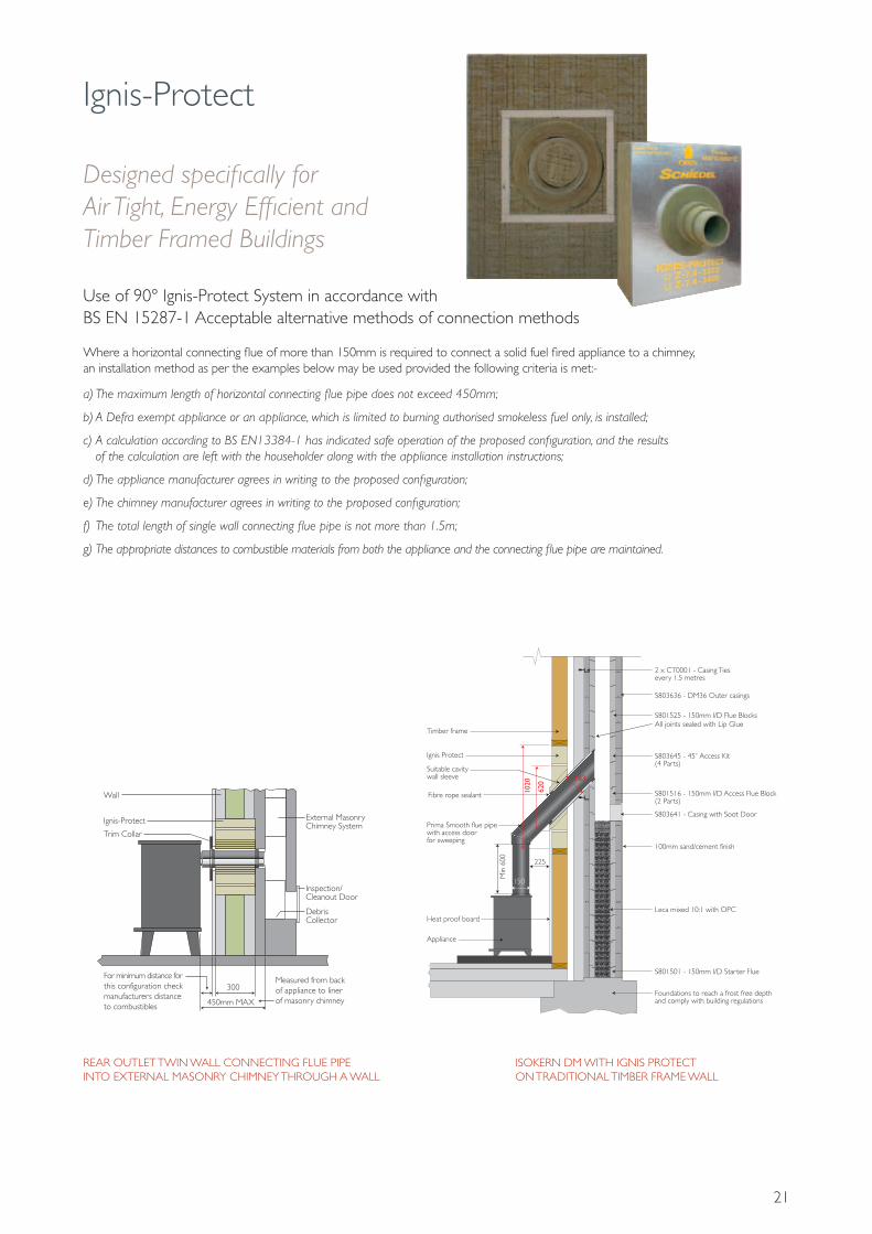
Ignis-Protect
Use of 90° Ignis-Protect System in accordance with BS EN 15287-1 Acceptable alternative methods of connection methods
Where a horizontal connecting flue of more than 150mm is required to connect a solid fuel fired appliance to a chimney, an installation method as per the examples below may be used provided the following criteria is met:-
a) The maximum length of horizontal connecting flue pipe does not exceed 450mm;
b) A Defra exempt appliance or an appliance, which is limited to burning authorised smokeless fuel only, is installed;
c) A calculation according to BS EN13384-1 has indicated safe operation of the proposed configuration, and the results of the calculation are left with the householder along with the appliance installation instructions;
d) The appliance manufacturer agrees in writing to the proposed configuration;
e) The chimney manufacturer agrees in writing to the proposed configuration;
f) The total length of single wall connecting flue pipe is not more than 1.5m;
g) The appropriate distances to combustible materials from both the appliance and the connecting flue pipe are maintained.
REAR OUTLET TWIN WALL CONNECTING FLUE PIPEINTO EXTERNAL MASONRY CHIMNEY THROUGH A WALL
Measured from back of appliance to outside surface of chimney
Measured from back of appliance to liner of masonry chimney
Twin Wall Chimney System
300
Wall Support
Tee Cap forDebris Collection/Cleaning Access
Trim Collar
Wall Wall Band
450mm MAX300
450mm MAX
External Masonry Chimney System
Inspection/Cleanout Door
Wall
Trim Collar
DebrisCollector
Wall Support
Measured from back of connecting flue pipe to outside surface of chimney
Tee Cap forDebris Collection/Cleaning Access
Twin Wall Chimney System
Wall
Inspection Bend
Trim CollarIgnis-Protect
Ignis-Protect Ignis-Protect
600 min
225For minimum distance for this configuration check manufacturers distanceto combustibles
No further bends allowed on this configuration
Wall Band
450mm MAX
Measured from back of connecting flue pipe to outside surface of chimney
Tee Cap forDebris Collection/Cleaning Access
Twin Wall Chimney System
Wall
Inspection Bend
Trim Collar
Ignis-Protect
225
Wall Support
Wall Band
450mm MAX
600 min
For minimum distance for this configuration check manufacturers distanceto combustibles
No further bends allowed on this configuration
For minimum distance for this configuration check manufacturers distanceto combustibles
For minimum distance for this configuration check manufacturers distanceto combustibles
Designed specifically for Air Tight, Energy Efficient and Timber Framed Buildings
ISOKERN DM WITH IGNIS PROTECT ON TRADITIONAL TIMBER FRAME WALL
Appliance
225
1020
620 183
Min
600
150
Heat proof board
Prima Smooth flue pipe with access door for sweeping
Timber frame
Ignis Protect
Suitable cavity wall sleeve
Fibre rope sealant
2 x CT0001 - Casing Ties every 1.5 metres
S803636 - DM36 Outer casings
S801525 - 150mm I/D Flue Blocks
S803645 - 45˚ Access Kit(4 Parts)
All joints sealed with Lip Glue
S801516 - 150mm I/D Access Flue Block(2 Parts)
S803641 - Casing with Soot Door
100mm sand/cement finish
Leca mixed 10:1 with OPC
S801501 - 150mm I/D Starter Flue
Foundations to reach a frost free depthand comply with building regulations

22
Ignis-Protect
COA: code on application
IGN
IS-P
ROT
ECT
Ignis-Protect 90˚ Version
SAPCode101841101842101843101844101845101846
Thickness(mm)
150200250300350400
Height(mm)
700700700700700700
Width(mm)
565565565565565565
PalletQuantity
1296442
Ignis-Protect 45˚ Version
SAPCodeCOACOACOACOACOACOACOA144032144033144034
Thickness(mm)
100150200250300350400450466500
Height(mm)
1020102010201320132013201320132013201320
Width(mm)
565565565565565565565565565565
PalletQuantity
181296442222
TYPICAL INSTALLATION OF 45˚ VERSION
Prima Smooth Stove Pipe
Plasterboard
Plasterboard
Permanently elastic sealing strip
Timber framework for Ignis-Protect
Ignis-Protect - 45° External version
Vapour barrier membrane
Schiedel Isokern Double Module System
Insulation
Damp proof barrier
Hearth

23
Useful Charts and Information
FLUE AREA AND LIP GLUE QUANTITY CHARTInt. Diameter of Liners & Flue Blocks (mm)
150
175
200
225
250
300
350
400
450
500
600
DM36 Casing
DM44 Casing
DM54 Casing
DM36 Offset Blocks
DM44 Offset Blocks
DM54 Offset Blocks
Ext. Diameter of Liner (mm)
200
235
250
285
310
360
416
470
530
590
710
Int. Areaof Liner (cm2)
177
240
314
397
491
707
962
1256
1590
1963
2826
Approx number ofjoints per bag of glue
16
14
12
11
10
9
7
6
5
5
4
6
5
4
5
4
3
LECA CALCULATION CHARTInt. Diameter of Liner (mm)
150
150
150
175
175
175
200
200
200
225
225
225
250
250
250
300
300
300
350
350
350
400
Ext. Diameter of Liner (mm)
200
200
200
235
235
235
250
250
250
285
285
285
310
310
310
360
360
360
416
416
416
470
Int. Sizeof Chimney (mm)
235 x 235
235 x 350
350 x 350
350 x 350
350 x 460
460 x 460
350 x 350
350 x 460
460 x 460
350 x 350
350 x 460
460 x 460
350 x 350
350 x 460
460 x 460
460 x 460
460 x 575
575 x 575
460 x 460
460 x 575
575 x 575
575 x 575
Bags perLinear metre
0.48
1.02
1.82
1.58
2.35
3.36
1.47
2.24
3.25
1.17
1.94
2.96
0.94
1.71
2.72
2.20
3.25
4.58
1.51
2.57
3.89
3.14

24
Useful Charts and Information
Offsetdistance
Height
100mm
Angle 30˚
PAIR OF BENDS
A
D
B C
For clearances to easily ignitable roof coverings such as thatch refer to diagram 2.2 of Approved Document J 2010 Edition
OFFSET DIMENSION CHARTInt. Diameter of Liner (mm)
150
150
150
175
175
175
200
200
200
225
225
225
250
250
250
300
300
300
350
350
350
Angle of Bend
15˚
30˚
45˚
15˚
30˚
45˚
15˚
30˚
45˚
15˚
30˚
45˚
15˚
30˚
45˚
15˚
30˚
45˚
15˚
30˚
45˚
OverallCombined Height
427
456
467
435
471
489
440
481
503
449
499
528
456
511
545
469
536
581
483
564
620
OffsetDistance (mm)
56
122
194
57
126
202
58
129
208
59
134
219
60
137
222
63
144
240
63
151
257
CHIMNEY HEIGHTS ABOVE ROOFPoint where flue passes through weather surface (Notes 1,2)
at or within 600mm of the ridge
elsewhere on a roof (whether pitched or flat)
below (on a pitched roof) or within 2300mm horizontally to an openable rooflight, dormer window or other opening (Note 3)
within 2300mm of an adjoining or adjacent building, whether or not beyond the boundary ( Note 3)
NOTES1. The weather surface is the building external surface, such as its roof, tiles or external walls.2. A flat roof has a pitch less than 10 .̊3. The clearances given for A or B as appropriate will also apply.
Clearances to flue outlets
at least 600mm above the ridge
at least 2300mm horizontally from the nearest point on the weather surface and:
A) at least 1000mm above the highest point of intersection of the chimney and the weather surface: or B) at least as high as the ridge
at least 1000mm above the top of the opening
at least 600mm above the adjacent building
A
B
C
D
CHIMNEY HEIGHTSOn solid fuel and wood burning applications , the minimum recommended flue height is 4.5m from above the fire place opening or top of the appliance . For shorter flue heights a draft calculation would be required in line with the flue sizing requirements of EN13384-1.The maximum freestanding stack height above the roof for a traditional coursed masonry chimney is 4.5 times the narrowest horizontal part of the chimney.

25
Useful Charts and Information
VENTILATION REQUIREMENTSIt is very important that sufficient air for combustion and ventilation is provided to the room containing the appliance, to enable correct and efficient working of the appliance and chimney system. Reference should be made to the appliance manufacturer’s instructions and recommendations are also given in the Building Regulations Document J, see below:
The carbon monoxide alarms should comply with BS EN 50291:2001.The carbon monoxide alarm must be located in the same room as the appliance:a) On the ceiling at least 300mm from any wall or if it is located on a wall, as high up as possible (above any doors and windows), but not within 150mm of the ceiling andb) between 1m and 3m horizontally from the appliance.N.B Provision of a carbon monoxide alarm should not be regarded as a substitute for correct installation and regular servicing.
CARBON MONOXIDE ALARMSWhere a new or replacement fixed solid fuel appliance is installed in a dwelling, a carbon monoxide alarm shouldbe provided in the room where the appliance is located.
VENTILATION REQUIREMENTS FOR SOLID FUEL
Type of Appliance
Notes:
Open appliance, such as an open fire with no throat, e.g. a fire under a canopy as in Diagram 23.
Open appliance, such as an open fire with a throat, as in Diagrams 22 and 29.
Other appliance, such as a stove, cooker or boiler, with a flue draught stabiliser.
1. Equivalent area is as measured according to the method in BS EN 13141-1:2004 or estimated according to paragraph 1.14. Divide the area given in mm2 by 100 to find the corresponding area in cm2.
2. For simple open fires as depicted in Diagram 29, the requirement can be met with room ventilation areas as follows:
3. Example: an appliance with a flue draught stabiliser and a rated output of 7kW would require an equivalent area of (5 x 300) + (2 x 850) = 3200mm2
4. It is unlikely that a dwelling constructed prior to 2008 will have an air permeability of less than 5.0m3/h.m2) at 50Pa unless extensive measures have been taken to improve air-tightness. See Appendix F.
Other appliance, such as a stove, cooker or boiler, with no flue draught stabiliser.
Permanently open air vent(s) with a total equivalent area of at least 50% of the cross sectional area of the flue.
Permanently open air vent(s) with a total equivalent area of at least 50% of the throat opening area. (2)
Permanently open air vents as below:
If design air permeability > 5.0m3/(h.m2) then300mm2/kW for first 5kW of appliance rated output850mm2/kW for balance of appliance rated output
If design air permeability ≤ 5.0m3/(h.m2) then850mm2/kW of appliance rated output (4)
Permanently open vents as below:
If design air permeability > 5.0m3/(h.m2) then550mm2/kW of appliance rated output above 5kW
If design air permeability ≤ 5.0m3/(h.m2) then550mm2/kW of appliance rated output (4)
Type and amount of Ventilation (1)
Nominal fire size (fireplace opening size)
Total equivalent area of permanently open air vents
500mm
20,500mm2
450mm
18,500mm2
400mm
16,500mm2
350mm
14,500mm2
MAGNUM COMBUSTION AIR REQUIREMENTSize of Magnum Firechest
500
950
1100
1200
Free Airin cm2
200
248
338
385
Free Airin mm2
20,000
24,800
33,800
38,500
MAGNUM FIREBRICK, LIP GLUE & MORTAR QUANTITYSize of Magnum Firechest
500
950
1100
1200
25mm thick Bricks
Included
40
40
40
50mm thick Bricks
Included
34
44
48
Lip Glue
2
5
6
6
Firebrick Mortar
Included
2
2
2
Please note the base bricks should be laid loose.

Schiedel Chimney SystemsUnit 8 & 9, Block A Holton RoadHolton Heath Industrial EstatePoole, Dorset BH16 6LGTel. +44 (0)1202 861650Fax. +44 (0)1202 [email protected]
Complementary products and servicesfrom Schiedel Chimney Systems
ICSTwin Wall Insulated System Chimney for gas,oil and multi-fuel applications.
• Simple push-fit jointing system• High efficiency Superwool insulation blanket• Capillary break prevents moisture being drawn through the joint• 80-300mm Diameter range
TECNOFLEX PLUSFor relining existing chimneys to take gas, oil,wood, multi-fuel appliances and open fires.
• Twin skin TecnoFlex Plus available in 316L or 904L options for oil, wood, multi-fuel & open fires
• 80-300mm Diameter range
ICIDThe NEW highly Insulated Twin Wall SystemChimney for traditional stoves, pellet stoves, biomass appliances, mini/micro CHP and condensing boilers capable of withstanding positive pressure.
• Easy twist lock connection• Effective insulation• 100-200 Internal diameter range
PRIMA SMOOTHSingle Wall Stainless Steel Connecting Flue Pipe for use on wood and multi-fuel applications.
• 316L Grade stainless steel• Available in matt black or steel finish• Excellent aesthetics• Lightweight• 125-200mm internal diameters
full details at www.schiedel.co.uk
IGNIS-PROTECTDesigned specifically for Air Tight, Energy Efficient and Timber Framed Buildings
Follow SchiedelUK on:
HETAS TRAININGCourses H001-H006 & H008-H009 available. See website for course prospectus and application form downloads or scan the QR code for a direct link.
ABSOLUT XPERTThe world’s 1st Passivhaus certified chimney system.
• GW3 rated - condensate resistant after a chimney fire• Safe connection to room sealed appliances passes blower door test with no additional rendering of the blocks


![[BS en 13084-2-2007] -- Free-standing Chimneys. Concrete Chimneys](https://img.dokumen.tips/doc/110x75/577c7e1f1a28abe054a09ebb/bs-en-13084-2-2007-free-standing-chimneys-concrete-chimneys.jpg)


