Embed Size (px)
Citation preview

System 575704 Control System
Operating Instructions

2
MAN0448.P65 Issue 12 Aug 04 5704 Control System005704-M-5001 A02279
Total environmental solutions
Ensure that you read and understand these instructions BEFOREoperating the equipment.
Please pay particular attention to the Safety Warnings.
WARNINGS
The items of equipment covered by this manual are:
1. Not designed or certified for use in hazardous areas.
2. Designed for indoor use only.
3. Not to be exposed to rain or moisture.
CAUTIONS
1. Use only approved parts and accessories with the 5704 ControlSystem.
2. To maintain safety standards, regular maintenance, calibrationand operation of the 5704 Control System by qualified personnelis essential.
IMPORTANT NOTICES
1. Zellweger Analytics Limited can take no responsibility for installationand/or use of its equipment if this is not done in accordance withthe appropriate issue and/or amendment of the manual.
2. The user of this manual should ensure that it is appropriate in alldetails to the exact equipment to be installed and/or operated. Ifin doubt, the user should contact Zellweger Analytics Limited foradvice.
Zellweger Analytics Limited reserve the right to change or revise theinformation supplied in this document without notice and withoutobligation to notify any person or organisation of such revision orchange.
If further details are required which do not appear in this manual,contact Zellweger Analytics Limited or one of their agents.

3
MAN0448.P65 Issue 12 Aug 04 5704 Control System
005704-M-5001 A02279
MANUAL ISSUE STATUS
The following table indicates the issue status of this manual and of theindividual chapters within the manual
ISSUE 12, AUGUST 2004
Section Pages File Issue
Front Pages 1 to 6 MAN0448A 12
Chapter 1 1-1 to 1-8 MAN0448B 12
Chapter 2 2-1 to 2-26 MAN0448C 12
Chapter 3 3-1 to 3-22 MAN0448D 12
Chapter 4 4-1 to 4-58 MAN0448E 12
Chapter 5 5-1 to 5-20 MAN0448G 12
Chapter 6 6-1 to 6-12 MAN0448H 12
Chapter 7 7-1 to 7-16 MAN0448I 12
Chapter 8 8-1 to 8-14 MAN0448J 12
Chapter 9 9-1 to 9-4 MAN0448K 12
Chapter 10 10-1 to 10-6 MAN0448L 12
Since the 'Front Pages' of a manual contain the above manual issuestatus table these pages will always carry the overall issue status ofthe manual. The remaining chapter issues will reflect the latest issueof those chapters at the time of print of a manual, e.g., Issue A, B, C,etc., for chapters of provisional information and 1, 2, 3, etc., forchapters of confirmed information.
HELP US TO HELP YOU
Every effort has been made to ensure the accuracy in the contents of ourdocuments, however, Zellweger Analytics Limited can assume noresponsibility for any errors or omissions in our documents or theirconsequences.
Zellweger Analytics Limited would greatly appreciate being informedof any errors or omissions that may be found in our documents. To thisend we include the following form for you to photocopy, complete andreturn to us so that we may take the appropriate action.

4
MAN0448.P65 Issue 12 Aug 04 5704 Control System005704-M-5001 A02279
Please inform me of the outcome of this change: Yes / No
For Marketing Communications, Zellweger Analytics Limited:
Actioned By: Date:
Response: Date:
To: Marketing Communications,Zellweger Analytics Limited,Hatch Pond House,4 Stinsford Road,Nuffield Estate,POOLE. Dorset.BH17 0RZ.United Kingdom.
Tel : +44 (0) 1202 676161Fax : +44 (0) 1202 678011email : [email protected]
From:
Address:
Tel :Fax :email :
I suggest the following corrections/changes be made to Chapter ........... Section ...........
HELP US TO HELP YOU
THANK YOU FOR YOUR ASSISTANCE.

5
MAN0448.P65 Issue 12 Aug 04 5704 Control System
005704-M-5001 A02279
MANUAL CONTENTS
Chapter
1. SYSTEM CONCEPT
2. SYSTEM DESCRIPTION
3. CONTROLS AND FACILITIES
4. INSTALLATION INSTRUCTIONS
5. COMMISSIONING AND MAINTENANCE INSTRUCTIONS
6. OPERATING INSTRUCTIONS
7. ENGINEER'S OPERATING INSTRUCTIONS
8. SPECIFICATION
9. ORDERING INFORMATION
10. SPECIAL CONDITIONS FOR SAFE USE ACCORDING TOEC-TYPE EXAMINATION CERTIFICATE BVS 04 ATEXG 001 X

6
MAN0448.P65 Issue 12 Aug 04 5704 Control System005704-M-5001 A02279
USER NOTES

1-1
MAN0448.P65 Issue 12 Aug 04 5704 Control System005704-M-5001 A02279
5704 SERIES
CONTROL SYSTEM
CHAPTER 1
SYSTEM CONCEPT
CHAPTER 1 - SYSTEM CONCEPT

1-2
MAN0448.P65 Issue 12 Aug 04 5704 Control System005704-M-5001 A02279
CONTENTS
Section Page
1. PRINCIPAL FEATURES 1-3
2. CONSTRUCTION 1-4
FIGURES
Figure Page
1. 5704 Control System 1-62. 5704 Control System Over View 1-7
CHAPTER 1 - SYSTEM CONCEPT

1-3
MAN0448.P65 Issue 12 Aug 04 5704 Control System005704-M-5001 A02279
1. PRINCIPAL FEATURES
The 5704 Series Control System is part of the System 57 family and isdesigned to monitor field mounted industrial gas detectors. The principalfeatures of the system are:
* Provides up to 64 channels of gas detection in a standard 19'' sub-rack using a 3U card format.
* Provides up to 32 channels of gas detection in a half 19'' sub-rackusing a 3U card format.
* Racking available for both front and rear access field wiring.
* Simple field connections for wire up to 2.5mm2 (14 AWG).
* Four channels per one inch wide card.
* Control cards removable without disturbing other wiring.
* Catalytic bridge or 4 - 20mA input control card versions.
* Alarm change-over relay output options.
* Optional time delayed operation of alarm relays.
* Multi-alarm mode for master, zoned and voted alarms.
* Rising, falling, STEL, LTEL and update alarm outputs.
* Remote inhibit and reset inputs per card.
* Optional 0 - 20mA or 4 - 20mA isolated monitor outputs perchannel.
* Easy to calibrate and operate using a dedicated Engineering Card.
* EMC compliant.
CHAPTER 1 - SYSTEM CONCEPT
1-4
MAN0448.P65 Issue 12 Aug 04 5704 Control System005704-M-5001 A02279
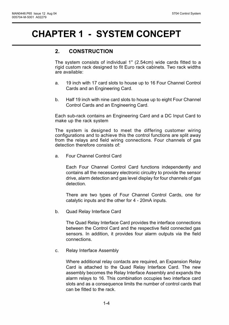
2. CONSTRUCTION
The system consists of individual 1'' (2.54cm) wide cards fitted to arigid custom rack designed to fit Euro rack cabinets. Two rack widthsare available:
a. 19 inch with 17 card slots to house up to 16 Four Channel ControlCards and an Engineering Card.
b. Half 19 inch with nine card slots to house up to eight Four ChannelControl Cards and an Engineering Card.
Each sub-rack contains an Engineering Card and a DC Input Card tomake up the rack system
The system is designed to meet the differing customer wiringconfigurations and to achieve this the control functions are split awayfrom the relays and field wiring connections. Four channels of gasdetection therefore consists of:
a. Four Channel Control Card
Each Four Channel Control Card functions independently andcontains all the necessary electronic circuitry to provide the sensordrive, alarm detection and gas level display for four channels of gasdetection.
There are two types of Four Channel Control Cards, one forcatalytic inputs and the other for 4 - 20mA inputs.
b. Quad Relay Interface Card
The Quad Relay Interface Card provides the interface connectionsbetween the Control Card and the respective field connected gassensors. In addition, it provides four alarm outputs via the fieldconnections.
c. Relay Interface Assembly
Where additional relay contacts are required, an Expansion RelayCard is attached to the Quad Relay Interface Card. The newassembly becomes the Relay Interface Assembly and expands thealarm relays to 16. This combination occupies two interface cardslots and as a consequence limits the number of control cards thatcan be fitted to the rack.
CHAPTER 1 - SYSTEM CONCEPT

1-5
MAN0448.P65 Issue 12 Aug 04 5704 Control System005704-M-5001 A02279
In a system where the field wiring is required to be connected to therear of the system, the rack is centrally divided into front and rearsections by a printed circuit board backplane which provides commonsignal routeing between individual Four Channel Control Cards. Thecontrol cards are fitted at the front of the rack while Quad RelayInterface Cards are fitted directly behind the associated Four ChannelControl Card at the rear of the rack. The control cards and theirrespective interface cards are interconnected by a plug and socketarrangement.
In a system where the field wiring is required to be connected to thefront of a system, the Four Channel Control Cards and Quad RelayInterface Cards are mounted one above the other in a 6U rack. Thebackplane printed circuit board still provides the common signal routeingbetween the individual Four Channel Control Cards, but short cablesat the rear of the cards connect each control card to their respectiveQuad Relay Interface Card.
Simple calibration and checking of the system is carried out usingpush buttons on the Engineering Card fitted in each rack. More complexconfiguration can be carried out using the RS232 link between theEngineering Card and an external IBM compatible personal computerrunning the engineering interface software.
When a Relay Interface Assembly is used, the resultant four channelcontrol assembly then takes up two card slots.
A mixture of 5704 and 5701 Control Cards may be fitted in the sameSystem 57 rack.
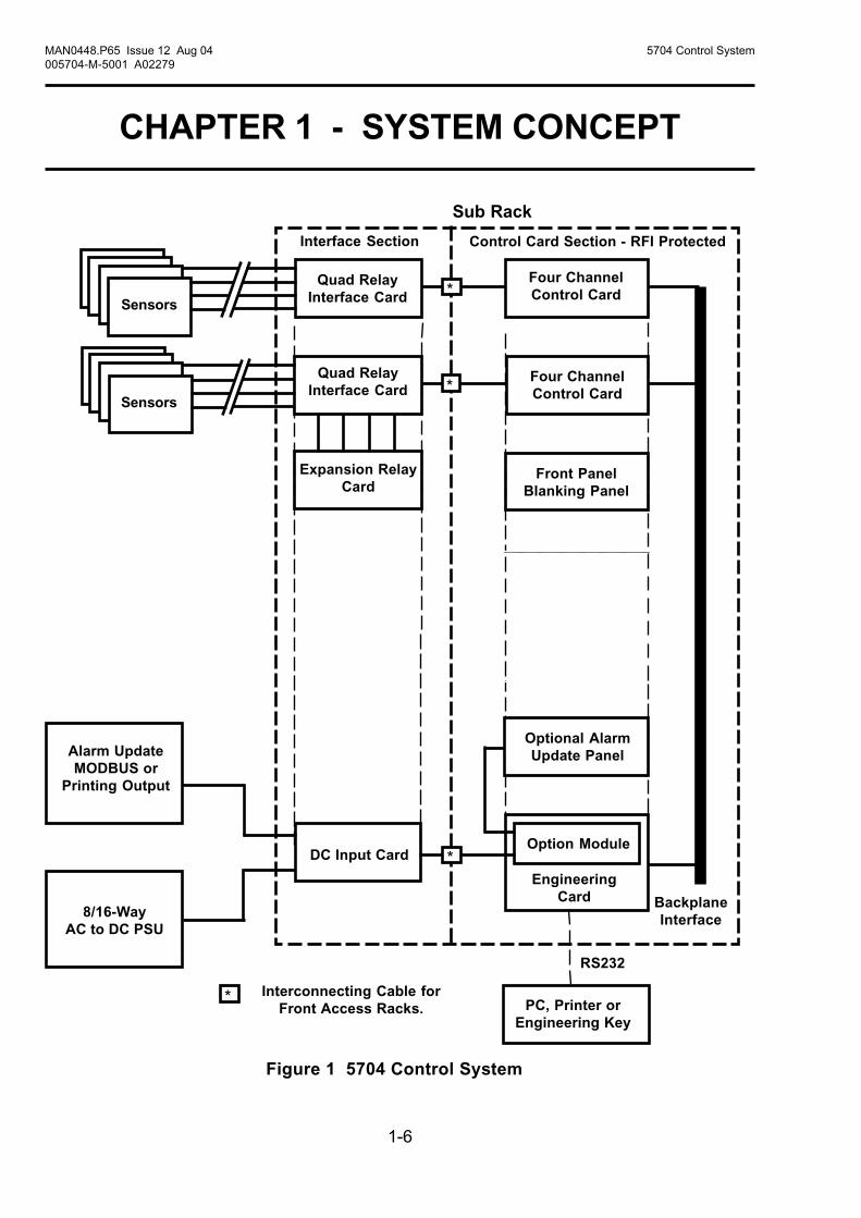
The 5704 Control System is shown in Figure 1.
CHAPTER 1 - SYSTEM CONCEPT
1-6
MAN0448.P65 Issue 12 Aug 04 5704 Control System005704-M-5001 A02279
Four ChannelControl Card
Quad RelayInterface Card
DC Input Card
EngineeringCard
8/16-WayAC to DC PSU
BackplaneInterface
Sensors
PC, Printer orEngineering Key
Interface Section Control Card Section - RFI Protected
Sub Rack
Figure 1 5704 Control System
RS232
Four ChannelControl Card
Quad RelayInterface Card
Expansion RelayCard
Front PanelBlanking Panel
Sensors
Option Module
Alarm UpdateMODBUS or
Printing Output
Optional AlarmUpdate Panel
*
*
*
* Interconnecting Cable forFront Access Racks.
CHAPTER 1 - SYSTEM CONCEPT

1-7
MAN0448.P65 Issue 12 Aug 04 5704 Control System005704-M-5001 A02279
EngineeringCard
Front Access8 or 16-Way
4 xSensor
16 x Relay
Relay InterfaceAssembly
OR
Figure 2 5704 Control System Over View
Rear Access8 or 16-Way
MODBUSInterfaceModule
Master AlarmUpdate Module
Event Print Module
BlankPanels
FourChannelControlCards
AnalogueOutput
Modules
4 x Relay
Quad RelayInterface Card
4 xSensor
DC InputCard
CHAPTER 1 - SYSTEM CONCEPT

1-8
MAN0448.P65 Issue 12 Aug 04 5704 Control System005704-M-5001 A02279
USER NOTES

2-1
MAN0448.P65 Issue 12 Aug 04 5704 Control System005704-M-5001 A02279
CHAPTER 2 - SYSTEM DESCRIPTION
5704 SERIES
CONTROL SYSTEM
CHAPTER 2
SYSTEM DESCRIPTION

2-2
MAN0448.P65 Issue 12 Aug 04 5704 Control System005704-M-5001 A02279
CHAPTER 2 - SYSTEM DESCRIPTION
CONTENTS
Section Page
1. INTRODUCTION 2-3
2. RACKS 2-4
3. CABINETS 2-6
4. FOUR CHANNEL CONTROL CARDS 2-8
4.1 General 2-84.2 Control Functions 2-94.3 Analogue Output Module 2-94.4 Physical Layout 2-10
5. QUAD RELAY INTERFACE CARD AND RELAYINTERFACE ASSEMBLY 2-11
5.1 General 2-115.2 Quad Relay Interface Card 2-115.3 Relay Interface Assembly 2-145.4 Expansion Relay Card 2-17
6. ENGINEERING CARD 2-18
7. DC INPUT CARD 2-19
7.1 General 2-207.2 DC Input Card Rear Access Connections 2-217.3 DC Input Card Front Access Connections 2-22
8. AC TO DC POWER SUPPLY UNITS 2-23
8.1 Types of Power Supply Unit 2-238.2 Power Supply Unit Upgrades 2-238.3 Power Supply Connections 2-238.4 8-Way AC to DC Power Supply Unit Layout 2-248.5 16-Way AC to DC Power Supply Unit Layout 2-248.6 50W Sub-Unit Layout 2-258.7 100W Sub-Unit Layout 2-25
9. FRONT PANEL BLANKING PANEL 2-26

2-3
MAN0448.P65 Issue 12 Aug 04 5704 Control System005704-M-5001 A02279
CHAPTER 2 - SYSTEM DESCRIPTION
1. INTRODUCTION
The 5704 Series Control System is a microprocessor based systemwhich displays the reading and status of connected gas detectors. Thesystem provides complex alarm handling facilities with a fullmaintenance capability.
A rack system is fitted with a number of Four Channel Control Cardseach with an associated Quad Relay Interface Card which providesthe necessary sensor input and optional relay output connections. ARelay Interface Assembly may be used to expand the number of relayoutputs available for each of the Four Channel Control Cards. Simplealarm handling and operation is provided by each channel controlcard.
Complex alarm handling is achieved by communication between aspecified number of control cards via the backplane of the rack.
An Engineering Card is fitted to each rack and provides control of therack backplane communications, control card interrogation andfacilitates maintenance.
In small systems power supplies, auxiliary power supplies and batteryback up systems can be connected to the rack via a DC Input Card. Inheavily populated installations of more than eight Four ChannelCatalytic Control Cards, power supplies are connected to eachindividual Four Channel Catalytic Control Card via its interface card.

2-4
MAN0448.P65 Issue 12 Aug 04 5704 Control System005704-M-5001 A02279
CHAPTER 2 - SYSTEM DESCRIPTION
2. RACKS
Each rack assembly contains a sub-rack, Engineering Card, DC InputCard, key kit and where necessary an interconnecting cable.
Dependent upon configuration, the control system is housed in one offour standard size sub-racks as follows:
a. Full 19 inch wide by 3U high - Part Number 05701-A-0511,for rear field wiring connections.
b. Full 19 inch wide by 6U high - Part Number 05701-A-0501,for front field wiring connections.
c. Half 19 inch wide by 3U high - Part Number 05701-A-0512,for rear field wiring connections.
d. Half 19 inch wide by 6U high - Part Number 05701-A-0502,for front field wiring connections.
All four versions have two separate chambers. One is sealed againstelectromagnetic interference and contains the control cards while theother chamber contains the relay interface cards. A backplane betweenthe two chambers provides a path for signal routeing between individualcontrol cards and the Engineering Card.
Typical Eight Card Rear Access Rack - Front View

2-5
MAN0448.P65 Issue 12 Aug 04 5704 Control System005704-M-5001 A02279
CHAPTER 2 - SYSTEM DESCRIPTION
Typical Eight Card Front Access Rack(Relay/Interface Chamber Front Cover Removed)
Typical Eight Card Rear Access Rack - Rear View

2-6
MAN0448.P65 Issue 12 Aug 04 5704 Control System005704-M-5001 A02279
CHAPTER 2 - SYSTEM DESCRIPTION
3. CABINETS
Two wall mounted cabinets are used to house:
a. the full width 16 card front access rack,(Part Number 05701-A-0451)
b. or the eight card half width front access rack.(Part Number 05701-A-0452)
A front door on each cabinet provides security and dust protection,while a clear panel in the door allows the channel card displays to beviewed when the door is closed. The base of each cabinet contains aselection of preformed knockout cable gland entries. A removableplate is fixed to the inside of the cabinet for mounting accessories.
Cabinet

2-7
MAN0448.P65 Issue 12 Aug 04 5704 Control System005704-M-5001 A02279
CHAPTER 2 - SYSTEM DESCRIPTION
Eight Card Cabinet Installation
Blanking Panel
8-Way AC to DC Power Supply Unit
Control Cards and Engineering Card
Interface/Relay Cards and DC Input Card
Accessory Plate suitable for mounting DINrails, circuit breakers, relays, etc.
16 Card Cabinet Installation
Blanking Panel
16-Way AC to DCPower Supply Unit
Control Cardsand Engineering Card
Interface/Relay Cardsand DC input Card
Accessory Plate suitablefor mounting DIN rails,circuit breakers, relays, etc.

2-8
MAN0448.P65 Issue 12 Aug 04 5704 Control System005704-M-5001 A02279
CHAPTER 2 - SYSTEM DESCRIPTION
4. FOUR CHANNEL CONTROL CARDS
4.1 General
The 5704 Four Channel Control Card providescontrol, display and alarm facilities for up to fourconnected gas detectors. The front panel backlitdisplay indicates the gas reading, channel statusand channel number while LEDs are used foralarms. A push-button is provided for resettingthe alarms and selecting the card for use withthe Engineering Card.
The operation of the control card ismicroprocessor controlled and is fully definablefor a wide range of connected gas detectorsand application requirements. The softwareconfiguration setup is stored in an EEPROM.
There are two types of control card dependingon the type of gas detector being fitted to thesystem:
a. Four Channel Control Card Catalytic InputPart Number 05704-A-0144.
b. Four Channel Control Card 4 - 20mA InputPart Number 05704-A-0145.
Optional Analogue Output Modules whichprovide a remote output of the channel cardreadings can be plugged into the Four ChannelControl Card. One module is required perchannel and different module types are availableto permit either current source or current sinkas required.
12345123451234512345123451234512345123451234512345123451234512345

2-9
MAN0448.P65 Issue 12 Aug 04 5704 Control System005704-M-5001 A02279
CHAPTER 2 - SYSTEM DESCRIPTION
4.2 Control Functions
The Four Channel Control Card carries out the control functions for upto four loops of gas detection as follows:
a. Provides the necessary voltages and currents to drive the connectedsensors.
b. Processes the incoming sensor signals.
c. Displays the signal levels, one at a time, on the front panel liquidcrystal display.
d. Compares each channel signal level with pre-defined alarm limits.
e. When the pre-defined alarm limits are exceeded, raises the alarmsby lighting up front panel LEDs and operating connected relays.
f. Informs other cards with the alarm status information.
g. Self validates the operation of its circuit components, softwareoperation and the condition of the sensor.
4.3 Analogue Output Module
Optional Analogue Output Modules may be factory fitted to the FourChannel Control Card and are used on each channel of gas detectionto provide a current loop output which follows the sensor signal level.This may be set electronically to produce a 0 - 20mA output or a 4 -20mA output and can be used to operate a chart recorder, data logger,PLC, etc. Two versions are available:
a. Analogue Output Module, Current SinkPart Number 04200-A-0145
b. Analogue Output Module, Current SourcePart Number 04200-A-0146

2-10
MAN0448.P65 Issue 12 Aug 04 5704 Control System005704-M-5001 A02279
CHAPTER 2 - SYSTEM DESCRIPTION
4.4 Physical Layout
The physical layout of the Four Channel Control Card is shown below.Analogue Output Modules, when fitted, plug into channel sockets asshown:
Plug-in Sockets for Analogue Output Modules(From left to right - Channel 1 2 3 4)
Liquid CrystalDisplay
LEDs
Reset/SelectPush Button
Switch
32-Way Connector (SK2)To Backplane
26-Way D Type Connector (SK1)To Quad Relay Interface Cards
Liquid CrystalDisplay
LEDs
Reset/SelectPush Button
Switch
32-Way Connector (SK2)To Backplane
26-Way D Type Connector (SK1)To Quad Relay Interface Cards
4 CHANNELCONTROL CARD
05704-A-0144 Iss.CATALYTIC INPUT
Ser/Batch No.
4 CHANNELCONTROL CARD
05704-A-0145 Iss.4 - 20mA LOOP INPUT
Ser/Batch No.
LK1 fitted to pins 1 - 2
LK1 fitted to pins 1 - 2 Identification Label
Identification Label

2-11
MAN0448.P65 Issue 12 Aug 04 5704 Control System005704-M-5001 A02279
CHAPTER 2 - SYSTEM DESCRIPTION
ExpansionRelay Card
Connector J1
26-Way D TypeConnector (SK1)To Four Channel
Control Cards
5. QUAD RELAY INTERFACE CARD AND RELAYINTERFACE ASSEMBLY
5.1 General
The Quad Relay Interface Card provides the interface between a FourChannel Control Card and the field wiring.
An Expansion Relay Card can also be factory fitted to the Quad RelayInterface Card and the resultant assembly is then known as the RelayInterface Assembly. This assembly is used to expand the standardfour relays available for alarms on the Quad Relay Interface to 16relays.
5.2 Quad Relay Interface Card (Part Number 05704-A-0121)
5.2.1 General
Provides connections between the four sensors and the control card.In addition, four single pole relays provide voltage free contact outputsthat can be configured for the A1 alarm level, A2 alarm level, A3 alarmlevel, fault or inhibit conditions and as individual alarms or masteralarms. Connections for power, remote inputs and analogue outputsare also provided.
The front and rear access connections are shown in Sections 5.2.2and 5.2.3 respectively while the physical layout is shown below:

2-12
MAN0448.P65 Issue 12 Aug 04 5704 Control System005704-M-5001 A02279
CHAPTER 2 - SYSTEM DESCRIPTION
5.2.2 Quad Relay Card Rear Access Connections
1. NC = Normally Closed. NO = Normally Open. COM = Common.
2. Relay contact conditions refer to the no power state of the relay.
3. The functions shown for terminals 1 to 12 are the default functions forrelays RL1 to RL4 only. For other configurations - refer to the configurationprintout.
RL1-NC (Master Fault) 1 2 RL1-NO (Master Fault)
RL1-COM (Master Fault) 3 4 RL2-COM (Master A1)
RL2-NC (Master A1) 5 6 RL2-NO (Master A1)
RL3-NC (Master A2) 7 8 RL3-NO (Master A2)
RL3-COM (Master A2) 9 10 RL4-COM (Master A3)
RL4-NC (Master A3) 11 12 RL4-NO (Master A3)
Ground 13 14 Ground
Channel 1 (S) 15 16 Channel 2 (S)
Channel 1 (01) 17 18 Channel 2 (01)
Channel 1 (NS) 19 20 Channel 2 (NS)
Channel 3 (S) 21 22 Channel 4 (S)
Channel 3 (01) 23 24 Channel 4 (01)
Channel 3 (NS) 25 26 Channel 4 (NS)
Analogue 24V 27 28 Analogue 0V
Analogue CH1 29 30 Analogue CH2
Analogue CH3 31 32 Analogue CH4
Remote Reset 33 34 Remote Inhibit
+24V Input 35 36 0V Input
Slot Location Label
Label forUser Terminal
Reference

2-13
MAN0448.P65 Issue 12 Aug 04 5704 Control System005704-M-5001 A02279
CHAPTER 2 - SYSTEM DESCRIPTION
5.2.3 Quad Relay Card Front Access Connections
1. NC = Normally Closed. NO = Normally Open. COM = Common.
2. Relay contact conditions refer to the no power state of the relay.
3. The functions shown for terminals 1 to 12 are the default functions forrelays RL1 to RL4 only. For other configurations - refer to the configurationprintout.
0V Input 36 35 +24V Input
Remote Inhibit 34 33 Remote Reset
Analogue CH4 32 31 Analogue CH3
Analogue CH2 30 29 Analogue CH1
Analogue 0V 28 27 Analogue 24V
Channel 4 (NS) 26 25 Channel 3 (NS)
Channel 4 (01) 24 23 Channel 3 (01)
Channel 4 (S) 22 21 Channel 3 (S)
Channel 2 (NS) 20 19 Channel 1 (NS)
Channel 2 (01) 18 17 Channel 1 (01)
Channel 2 (S) 16 15 Channel 1 (S)
Ground 14 13 Ground
RL4-NO (Master A3) 12 11 RL4-NC (Master A3)
RL4-COM (Master A3) 10 9 RL3-COM (Master A2)
RL3-NO (Master A2) 8 7 RL3-NC (Master A2)
RL2-NO (Master A1) 6 5 RL2-NC (Master A1)
RL2-COM (Master A1) 4 3 RL1-COM (Master Fault)
RL1-NO (Master Fault) 2 1 RL1-NC (Master Fault)
Label forUser Terminal
Reference
Slot Location Label

2-14
MAN0448.P65 Issue 12 Aug 04 5704 Control System005704-M-5001 A02279
CHAPTER 2 - SYSTEM DESCRIPTION
5.3 Relay Interface Assembly (Part Number 05704-A-0131)
5.3.1 General
The following diagrams show the Expansion Relay Card fitted to theQuad Interface Relay Card to form a Relay Interface Assembly:
Front AccessTop View
ExpansionRelayCard
Quad RelayInterface
Card
ExpansionRelayCard
Quad RelayInterface
Card
ExpansionRelayCard
Quad RelayInterface
Card
Rear AccessFront View
Front AccessFront View
1. For details of the Quad Interface Card, see Section 5.2.
2. For details of the Expansion Relay Card, see Sections 5.4.

2-15
MAN0448.P65 Issue 12 Aug 04 5704 Control System005704-M-5001 A02279
CHAPTER 2 - SYSTEM DESCRIPTION
5.3.2 Relay Interface Assembly Rear Access Connections
1. NC = Normally Closed. NO = Normally Open. COM = Common.
2. Relay contact conditions refer to the no power state of the relay.
EXPANSION CARD
Left Right
1 RL5-NC (CH1 Fault) 2 RL5-NO (CH1 Fault)
3 RL5-COM (CH1 Fault) 4 RL6-COM (CH2 Fault)
5 RL6-NC (CH2 Fault) 6 RL6-NO (CH2 Fault)
7 RL7-NC (CH3 Fault) 8 RL7-NO (CH3 Fault)
9 RL7-COM (CH3 Fault) 10 RL8-COM (CH4 Fault)
11 RL8-NC (CH4 Fault) 12 RL8-NO (CH4 Fault)
13 RL9-NC (CH1 A1) 14 RL9-NO (CH1 A1)
15 RL9-COM (CH1 A1) 16 RL10-COM (CH2 A1)
17 RL10-NC (CH2 A1) 18 RL10-NO (CH2 A1)
19 RL11-NC (CH3 A1) 20 RL11-NO (CH3 A
21 RL11-COM (CH3 A1) 22 RL12-COM (CH4 A1)
23 RL12-NC (CH4 A1) 24 RL12-NO (CH4 A1)
25 RL13-NO (CH1 A2) 26 RL13-COM (CH1 A2)
27 RL14-NO (CH2 A2) 28 RL14-COM (CH2 A2)
29 RL15-NO (CH3 A2) 30 RL15-COM (CH3 A2)
31 RL16-NO (CH4 A2) 32 RL16-COM (CH4 A2)
33 Ground 34 Ground
35 Not Used 36 Not Used
ExpansionCard
Quad RelayCard
QUAD RELAY CARD
Left Right
1 RL1-NC (Master Fault) 2 RL1-NO (Master Fault)
3 RL1-COM (Master Fault) 4 RL2-COM (Master A1)
5 RL2-NC (Master A1) 6 RL2-NO (Master A1)
7 RL3-NC (Master A2) 8 RL3-NO (Master A2)
9 RL3-COM (Master A2) 10 RL4-COM (Master A3)
11 RL4-NC (Master A3) 12 RL4-NO (Master A3)
13 Ground 14 Ground
15 Channel 1 (S) 16 Channel 2 (S)
17 Channel 1 (01) 18 Channel 2 (01)
19 Channel 1 (NS) 20 Channel 2 (NS)
21 Channel 3 (S) 22 Channel 4 (S)
23 Channel 3 (01) 24 Channel 4 (01)
25 Channel 3 (NS) 26 Channel 4 (NS)
27 Analogue 24V 28 Analogue 0V
29 Analogue CH1 30 Analogue CH2
31 Analogue CH3 32 Analogue CH4
33 Remote Reset 34 Remote Inhibit
35 +24V Input 36 0V Input
SlotLocation
Label
Label forUser Terminal
Reference

2-16
MAN0448.P65 Issue 12 Aug 04 5704 Control System005704-M-5001 A02279
CHAPTER 2 - SYSTEM DESCRIPTION
5.3.3 Relay Interface Assembly Front Access Connections
1. NC = Normally Closed. NO = Normally Open. COM = Common.
2. Relay contact conditions refer to the no power state of the relay.
EXPANSION CARD
Left Right
36 Not Used 35 Not Used
34 Ground 33 Ground
32 RL16-COM (CH4 A2) 31 RL16-NO (CH4 A2)
30 RL15-COM (CH3 A2) 29 RL15-NO (CH3 A2)
28 RL14-COM (CH2 A2) 27 RL14-NO (CH2 A2)
26 RL13-COM (CH1 A2) 25 RL13-NO (CH1 A2)
24 RL12-NO (CH4 A1) 23 RL12-NC (CH4 A1)
22 RL12-COM (CH4 A1) 21 RL11-COM (CH3 A1)
20 RL11-NO (CH3 A1) 19 RL11-NC (CH3 A1)
18 RL10-NO (CH2 A1) 17 RL10-NC (CH2 A1)
16 RL10-COM (CH2 A1) 15 RL9-COM (CH1 A1)
14 RL9-NO (CH1 A1 13 RL9-NC (CH1 A1)
12 RL8-NO (CH4 Fault) 11 RL8-NC (CH4 Fault)
10 RL8-COM (CH4 Fault) 9 RL7-COM (CH3 Fault)
8 RL7-NO (CH3 Fault) 7 RL7-NC (CH3 Fault)
6 RL6-NO (CH2 Fault) 5 RL6-NC (CH2 Fault)
4 RL6-COM (CH2 Fault) 3 RL5 - COM (CH1 Fault)
2 RL5-NO (CH1 Fault) 1 RL5-NC (CH1 Fault)
QUAD RELAY CARD
Left Right
36 0V Input 35 +24V Input
34 Remote Inhibit 33 Remote Reset
32 Analogue CH4 31 Analogue CH3
30 Analogue CH2 29 Analogue CH1
28 Analogue 0V 27 Analogue 24V
26 Channel 4 (NS) 25 Channel 3 (NS)
24 Channel 4 (01) 23 Channel 3 (01)
22 Channel 4 (S) 21 Channel 3 (S)
20 Channel 2 (NS) 19 Channel 1 (NS)
18 Channel 2 (01) 17 Channel 1 (01)
16 Channel 2 (S) 15 Channel 1 (S)
14 Ground 13 Ground
12 RL4-NO (Master A3) 11 RL4-NC (Master A3)
10 RL4-COM (Master A3) 9 RL3-COM (Master A2)
8 RL3-NO (Master A2) 7 RL3-NC (Master A2)
6 RL2-NO (Master A1) 5 RL2-NC (Master A1)
4 RL2-COM (Master A1) 3 RL1-COM (Master Fault)
2 RL1-NO (Master Fault) 1 RL1-NC (Master Fault)
ExpansionCard
Quad RelayCard
SlotLocation
Label
Label forUser Terminal
Reference

2-17
MAN0448.P65 Issue 12 Aug 04 5704 Control System005704-M-5001 A02279
CHAPTER 2 - SYSTEM DESCRIPTION
5.4 Expansion Relay Card
The Expansion Relay Card provides relay expansion for a Four ChannelControl Card and the Quad Relay Interface Card. The ExpansionRelay Card is connected to the Quad Relay Interface Card and provides12 additional relays, eight of which are single pole changeover andfour are single pole single throw. The relays can be configured for A1,A2, A3, fault or inhibit alarms and as individual or master outputs.
When the Expansion Relay Card is connected to the Quad RelayInterface Card, the pair of cards take up two slots of the rack. For thisreason a blank panel has to be fitted to the rack front panel adjacent tothe associated Four Channel Control Card.
The front and rear access connections are shown in Sections 5.3.2and 5.3.3 respectively while the physical layout is shown below:
Quad Relay CardConnector J1

2-18
MAN0448.P65 Issue 12 Aug 04 5704 Control System005704-M-5001 A02279
CHAPTER 2 - SYSTEM DESCRIPTION
a. Routeing of the 24V dc input from the DC InputCard to the backplane of the rack.
b. A backplane serial communications controllerand monitor.
c. A time and date reference.
d. An RS232 external engineering interface.
e. Depending upon the security level, the operationof the following rack facilities:
Catalytic sensor head current monitoring andadjustment.
Alarm set point checking, adjustment andtesting.
Sensor signal zero adjustment.
Sensor signal span adjustment and setting ofsensor life monitoring values.
Sensor line monitoring.
Enabling of control card alarm inhibit.
Checking and adjustment of the system clock.
f. Self validation of the operation of its circuitcomponents, software operation and thebackplane communications.
g. A socket for the addition of special modules thatexpand the System 57 capabilities.
6. ENGINEERING CARD PART NUMBER (05701-A-0361)
The Engineering Card is used on a System 57 rack to provide acommon interface that enables the user to perform all the requiredfunctions to commission and operate each fitted control card.
The front panel is fitted with a series of tactile push-buttons for theoperation of various functions, LEDs to provide rack power andcommunications status and a mini DIN socket for the connection of aserial printer, computer or an engineering key. The Engineering Key isused to unlock functions that can alter the operation of a control card.
The Engineering Card is always fitted into the right-hand slot of therack and provides:
CLOCKINHIBIT
1ST SPANSPAN
SIGNALZERO
ALARMSBEAD mA

2-19
MAN0448.P65 Issue 12 Aug 04 5704 Control System005704-M-5001 A02279
CHAPTER 2 - SYSTEM DESCRIPTION
One of four optional modules may be fitted to the Engineering Card:
a. Master Alarm Update Module
This facility provides an indication when a new alarm occurs on anychannel in the rack, even if a previous alarm condition alreadyexists.
b. Event Printing Module
This facility provides time stamped reporting of alarm and faultevents as they occur and system status at predetermined regularintervals.
c. Modbus Interface Module RS422/485
This facility provides for digital communication between theSystem 57 Control System and an external computer system usingthe RS422/485 serial data format and the Modbus communicationprotocol.
d. Modbus Interface Module RS232
This facility provides for digital communication between theSystem 57 Control System and an external computer system usingthe RS232 serial data format and the Modbus communicationprotocol.

2-20
MAN0448.P65 Issue 12 Aug 04 5704 Control System005704-M-5001 A02279
CHAPTER 2 - SYSTEM DESCRIPTION
7. DC INPUT CARD (PART NUMBER 05701-A-0325)
7.1 General
The dc power to the rack can enter the sub-rack via the DC Input Card.This power may be supplied by the user from an external nominal 24Vdc supply. The dc supply is routed through the Engineering Card andsub-rack back plane to all cards in the rack and is protected by a fuseon the DC Input Card. There is a two part terminal block, TB1, to aidremoval of the card without disconnecting each of the connectedwires.
To prevent excessive current flow along the rack backplane ininstallations where more than eight 5704 Catalytic Cards are used, it isrecommended that the Control Cards are powered via their associatedQuad Relay Interface Card and the DC Input Card used to power theEngineering Card only.
If required, a stand-by backup battery supply may also be connected tothe auxiliary dc input connections.
The PSU and AUX connections are isolated from each other by diodes.
The DC Input Card also provides RFI filtering and reverse polarityprotection.
In addition, the DC Input Card provides an interface to the EngineeringCard plug-in modules via TB2. The functions of the six terminals willvary dependent upon the module fitted. For full details refer to:
a. 05701-M-5006System 57 Control SystemModbus Interface Option RS485/422
b. 05701-M-5007 System 57 Control SystemEvent Printing Option RS232
c. 05701-M-5009 System 57 Control SystemAlarm Update Option

2-21
MAN0448.P65 Issue 12 Aug 04 5704 Control System005704-M-5001 A02279
CHAPTER 2 - SYSTEM DESCRIPTION
7.2 DC Input Card Rear Access Connections
TB1
12 +24V In (PSU 1)
11 0V In (PSU 1)
10 +24V In (PSU 2*) or +24V Out (PSU 1)
9 0V In (PSU 2) or 0V Out (PSU 1)
8 +24V In (AUX 1)
7 0V In (AUX 1)
6 +24V In (AUX 2*) or +24V Out (AUX 1)
5 0V In (AUX 2) or 0V Out (AUX 1)
4 +24V Out (Fused)
3 0V Out (Fused)
2 Ground
1 Ground
TB2
6
5
4
3
2
1
For Engineering Card Modules(Functions will vary)
Note: For 5704 systems with more than eight catalytic control cards, it isrecommended that the dc power is connected direct to eachchannels' Quad Relay Card.
* PSU 1 and PSU 2 (and AUX 1 and AUX 2) must becompatible with parallel connection.
Slot Location Label
Label forUser Terminal
Reference

2-22
MAN0448.P65 Issue 12 Aug 04 5704 Control System005704-M-5001 A02279
CHAPTER 2 - SYSTEM DESCRIPTION
7.3 DC Input Card Front Access Connections
TB2
1
2
3
4
5
6
TB1
1 Ground
2 Ground
3 0V Out (Fused)
4 +24V Out (Fused)
5 0V In (AUX 2) or 0V Out (AUX 1)
6 +24V In (AUX 2*) or +24V Out (AUX 1)
7 0V In (AUX 1)
8 +24V In (AUX 1)
9 0V In (PSU 2) or 0V Out (PSU 1)
10 +24V In (PSU 2*) or +24V Out (PSU 1)
11 0V In (PSU 1)
12 +24V In (PSU 1)
For Engineering Card Modules(Functions will vary)
Note: For 5704 systems with more than eight catalytic control cards, it isrecommended that the dc power is connected direct to eachchannels' Quad Relay Card.
* PSU 1 and PSU 2 (and AUX 1 and AUX 2) must becompatible with parallel connection.
Slot Location Label
Label forUser Terminal
Reference

2-23
MAN0448.P65 Issue 12 Aug 04 5704 Control System005704-M-5001 A02279
CHAPTER 2 - SYSTEM DESCRIPTION
8. AC TO DC POWER SUPPLY UNITS
8.1 Types of Power Supply Unit
There are two types of AC to DC power supply units:
a. 8-Way AC to DC Power Supply Unit (Part Number 05701-A-0406)
A 1U high half width 19 inch rack mounted unit that contains asingle 50W Switched Mode AC to DC Power Supply Module.
b. 16-Way AC to DC Power Supply Unit (Part Number 05701-A-0405)
A 1U high 19 inch rack mounted unit that contains a single 50WSwitched Mode AC to DC Power Supply Module.
Both power supply units will operate from an 85V to 264V, 47Hz to440Hz ac supply, or a 110V to 340V dc supply (Refer to ZellwegerAnalytics for information on dc supplies).
8.2 Power Supply Unit Upgrades
Both power supply units are provided with internal connections toenable a power upgrade to 100W by the addition of a second 50WSwitched Mode AC to DC Power Supply Module (Part Number 05701-A-0440).
A second sub-unit (Part Number 05701-A-0441) can be fitted to thebasic 16-way power supply unit if more than 100W is required tooperate the system. The additional sub-unit will contain a 50W SwitchedMode AC to DC Power Supply Module as standard and will thereforegive an additional 50W of available power. If required a further 50WSwitched Mode AC to DC Power Supply Module (Part Number 05701-A-0440) can be added to this second sub-unit to bring the poweravailability up to 200W.
The switched mode power supply modules used are fully overloadprotected and are designed to be connected together.
8.3 Power Supply Connections
The input ac power supply is connected via a three core cable at therear of each unit.
The nominal 24V dc output supply is connected via a twin core cableat the rear of each unit.
2-24
MAN0448.P65 Issue 12 Aug 04 5704 Control System005704-M-5001 A02279
CHAPTER 2 - SYSTEM DESCRIPTION
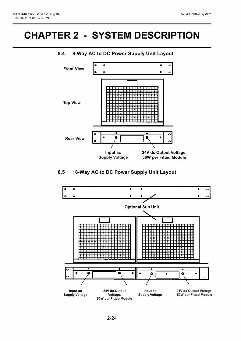
8.4 8-Way AC to DC Power Supply Unit Layout
8.5 16-Way AC to DC Power Supply Unit Layout
Front View
Top View
Rear View
24V dc Output Voltage.50W per Fitted Module
Input acSupply Voltage
Input acSupply Voltage
24V dc OutputVoltage.
50W per Fitted Module
Input acSupply Voltage
24V dc Output Voltage.50W per Fitted Module
Optional Sub Unit

2-25
MAN0448.P65 Issue 12 Aug 04 5704 Control System005704-M-5001 A02279
CHAPTER 2 - SYSTEM DESCRIPTION
8.6 50W Sub-Unit Layout
The 50W Sub-unit is fitted with a single 50W Switched Mode AC to DCPower Supply Module as shown below:
This type of unit is identified on the identification label as follows:
8.7 100W Sub-Unit Layout
The 100W Sub-unit is a 50W Sub-unit with an additional 50WSwitched Mode AC to DC Power Supply Module fitted as shownbelow:
This type of unit is identified on the identification label as follows:
Top View(with coverremoved)
50W Switched ModeAC to DC PowerSupply Module
50W Switched ModeAC to DC PowerSupply Module
Additional 50WSwitched Mode ACto DC PowerSupply Module
Top View(with coverremoved)
POWER SUPPLY UNIT 05700-A-0405 Iss. 2
INPUT = 85 - 264V AC OUTPUT = 24V DC47 - 440Hz POWER = 50W
OR 110 - 340V DC = 100W
Indicates50W Unit
POWER SUPPLY UNIT 05700-A-0405 Iss. 2
INPUT = 85 - 264V AC OUTPUT = 24V DC47 - 440Hz POWER = 50W
OR 110 - 340V DC = 100W
Indicates100W Unit

2-26
MAN0448.P65 Issue 12 Aug 04 5704 Control System005704-M-5001 A02279
CHAPTER 2 - SYSTEM DESCRIPTION
9. FRONT PANEL BLANKING PANEL
Matching blank front panels are available for fitting to the rack in allunused control card spaces.

2-27
MAN0448.P65 Issue 12 Aug 04 5704 Control System005704-M-5001 A02279
CHAPTER 2 - SYSTEM DESCRIPTIONUSER NOTES

3-1
MAN0448.P65 Issue 12 Aug 04 5704 Control System005704-M-5001 A02279
CHAPTER 3 CONTROLS AND FACILITIES
5704 SERIES
CONTROL SYSTEM
CHAPTER 3
CONTROLS AND FACILITIES

3-2
CHAPTER 3 CONTROLS AND FACILITIES
MAN0448.P65 Issue 12 Aug 04 5704 Control System005704-M-5001 A02279
CONTENTS
Section Page
1. Introduction 3-3
2. Four Channel Control Card 3-8
2.1 General 3-82.2 Liquid Crystal Display 3-82.3 Status LEDs 3-112.4 Reset/Select Push-button 3-142.5 Extraction Slot 3-152.6 Display Label and Cover 3-15
3. Engineering Card 3-17
3.1 General 3-173.2 LED Indicators 3-173.3 Engineering Push-buttons 3-183.4 Engineering Serial Port 3-21

3-3
MAN0448.P65 Issue 12 Aug 04 5704 Control System005704-M-5001 A02279
CHAPTER 3 CONTROLS AND FACILITIES
1. INTRODUCTION
The 5704 Series Control System is equipped to provide the operationaland engineering facilities necessary to fully maintain a system of gasdetection equipment.
Each control card within a rack system displays a sensor reading,alarm status condition and channel reading number.
Further information can be gathered and, depending on the securitystatus, certain settings can be adjusted by means of an EngineeringCard fitted to the rack.
The relay outputs of the system are configured to provide a range ofoutput alarm functions as follows:
a. Fault Alarm
The fault alarm activates when a fault is detected in the controlchannel or associated sensor and is not user configurable. Inaddition the FAULT LED will be illuminated as described in Section2.3.1a.
b. Inhibit Alarm
The inhibit alarm activates when the system alarms are inhibited forany reason and is not user configurable. In addition the INHIBITLED will be illuminated as described in Section 2.3.1b.
c. A1, A2 and A3 Level Alarms
The A1, A2 and A3 level alarms are activated when the level of gasbeing measured crosses the preconfigured alarm threshold. Inaddition the relevant LED will be illuminated as described in Section2.3.1c, d and e.
d. STEL Alarm (Short Term Exposure Limit).
The STEL alarm will be activated when the time weighted averageconcentration of a toxic gas, usually averaged over 10 or 15minutes, crosses a preconfigured threshold. The control card alarmLED, associated during setup to the STEL alarm, will be illuminatedas described in Section 2.3.1f and the message display will showSTEL.

3-4
CHAPTER 3 CONTROLS AND FACILITIES
MAN0448.P65 Issue 12 Aug 04 5704 Control System005704-M-5001 A02279
e. LTEL Alarm (Long Term Exposure Limit).
The LTEL alarm will be activated when the time weighted averageconcentration of a toxic gas, usually averaged over 8 hours, crossesa preconfigured threshold. The control card alarm LED, associatedduring setup to the LTEL alarm, will be illuminated as described inSection 2.3.1f and the message display will show LTEL.
f. Individual Alarm
An individual alarm is caused by the input to an individual controlchannel crossing a preconfigured threshold and is not related toany other control channel. The relevant LED (A1, A2, A3, Fault,Inhibit) will illuminate on the control card with the alarm condition asdescribed in Section 2.3.1.
CAUTION*
Depending upon the configuration, control cards configured for thefollowing Zoned, Master or Voted alarms may not give indvidualalarm outputs.
g. Zoned Alarm*
A zoned alarm is caused by the input to any control channel, from asensor in a designated area, crossing a preconfigured threshold.The relevant LED (A1, A2, A3, Fault, Inhibit) will illuminate asdescribed in Section 2.3.1 on the control card with the alarmcondition and the message display of the control card designatedZone Master Card will show ZONE.
h. Master Alarm*
A master alarm is caused by the input to any designated controlchannel within a single rack crossing a preconfigured threshold.The relevant LED (A1, A2, A3, Fault, Inhibit) will illuminate asdescribed in Section 2.3.1 on the control card with the alarmcondition and the message display of the control card designatedthe Master Control Card will show MSTR.

3-5
MAN0448.P65 Issue 12 Aug 04 5704 Control System005704-M-5001 A02279
CHAPTER 3 CONTROLS AND FACILITIES
i. Voted Alarm*
A voted alarm is caused by the simultaneous presence of anidentical alarm on more than one control channel within apreconfigured group. The relevant LED (A1, A2, A3, Fault, Inhibit)will illuminate as described in Section 2.3.1 on the control cardswith the alarm conditions and the message display of the controlcard designated the Vote Master Card will show VOTE.
Vote compensation may be applied to the voted alarm outputoperation by selecting one of the following configurations:
a. No compensation.b. Faults counted as alarms.c. Faults and inhibits counted as alarms.d. Vote count reduction on faults.e. Vote count reduction on faults and inhibit.
Vote compensation is useful to ensure that sensors in fault (orinhibit) do not prevent voted alarm outputs.
Note: Vote compension should not be used with software Version1V5 or earlier.
j. Update Alarm
The update alarm facility provides a common alarm indicationwhenever a new alarm occurs, even if a previous alarm conditionexists. The update alarm can be configured to operate on a singlecard or on a grouped alarm e.g. master or zoned. The update alarmis especially useful in systems configured with only master orgroup/zone relays, where the occurrence of subsequent alarms willnot cause further relay output compared to that caused by the initialalarm. The relevant LED (A1, A2, A3, Fault, Inhibit) will illuminateon the control card with the alarm condition as described in Section2.3.1. The ATTN LED will also illuminate as described in Section2.3.2b and the message display will show the cause of the updatealarm, e.g., -FT-, -IN-, -A1-, etc.
When relays are used for signalling update alarms, no other alarmsor messages must be allocated to them.
Note: Update alarms should not be used with software Version 1V5 orearlier.

3-6
CHAPTER 3 CONTROLS AND FACILITIES
MAN0448.P65 Issue 12 Aug 04 5704 Control System005704-M-5001 A02279
k. Rising Alarm
A rising alarm is caused by a rising level of the parameter beingmeasured crossing a preconfigured threshold. This will also causethe associated alarm LED to illuminate as described in Section2.3.1.
l. Falling Alarm
A falling alarm is caused by a falling level of the parameter beingmeasured crossing a preconfigured threshold. This will also causethe associated alarm LED to illuminate as described in Section2.3.1.
m. Latched Alarm
A latched alarm is an alarm that will remain active even though thelevel monitored no longer crosses the alarm threshold. The alarmLED will remain lit until the alarm reset is operated.
n. Non-latched Alarm
A non-latched alarm is an alarm that only remains active while thelevel being monitored crosses the alarm threshold. The alarm LEDwill remain lit while the alarm level remains but will automatically bereset when the level monitored no longer crosses the alarmthreshold.
o. Normally Energised
A normally energised relay is activated when the power is removedfrom it, (eg. in the event of a system power failure). The LEDs willilluminate when an alarm or fault condition occurs irrespective ofthe relay configured state.
p. Normally De-energised
A normally de-energised relay is activated when the power isapplied to it, (eg. in the event of an alarm condition). The LEDs willilluminate when an alarm or fault condition occurs irrespective ofthe relay configured state.

3-7
MAN0448.P65 Issue 12 Aug 04 5704 Control System005704-M-5001 A02279
CHAPTER 3 CONTROLS AND FACILITIES
q. Time Delay Alarms
The operation in response to alarm events of certain relays may bemodified by applying a delay function to the relays. Time delayfunctions are available to delay the activation of a relay for a shortperiod after an alarm event occurs and/or to maintain relay activationfor a period after the alarm event has cleared. The time delayfacilities are available for:
i. Relays 1 to 4 if the Quad Relay Interface Card is fitted.
ii. Relays 1 to 8 if the Relay Interface Assembly is fitted.
The time delay function is useful to prevent spurious alarms and toensure appropriate minimum operating times for external electricalapparatus connected to the relay.

3-8
CHAPTER 3 CONTROLS AND FACILITIES
MAN0448.P65 Issue 12 Aug 04 5704 Control System005704-M-5001 A02279
and the resultant values and anynecessary alarm action,depending on the channelconfiguration, is carried out.
The channel card front panel canbe subdivided into five areas:
Display Label and Cover.
LCD Display.
Status LEDs.
Reset/Select Push-button.
Extraction Slot.
2. FOUR CHANNEL CONTROL CARD
2.1 GeneralThe Four Channel Control Card provides the necessary power suppliesto the associated sensors and conditions the incoming sensor signals.The received sensor signals are then processed by the microprocessor
2.2 Liquid Crystal Display
2.2.1 General
The backlit LCD provides a display of the selected sensor reading andits status, or if maintenance is being carried out on a sensor, informationon the sensor set points and calibration data.
123456123456123456123456123456123456123456123456123456123456123456123456

3-9
MAN0448.P65 Issue 12 Aug 04 5704 Control System005704-M-5001 A02279
CHAPTER 3 CONTROLS AND FACILITIES
The method of displaying each channelsinformation can be selected from one of thefollowing:
a. Automatic sequencing.
b. Highest reading.
c. Combination of automatic sequencing andhighest reading.
d. Manually selected.
The display can be divided into four parts:
Analogue Display.
Message Display
Digital Display.
Icon Display.
2.2.2 Analogue Display
This consists of 25 segments providing anindication of the sensor gas reading in the formof an analogue bargraph which covers the sensorrange between -10% and +110% fsd.
There are two possible modes of operation:
a. Solid in which the segments fill the areabetween zero and the actual gas reading.
b. Single Line in which a single segmentindicates the actual gas reading.
Each of these modes can be operated as eithera rising or falling display.
A peak reading facility is available whichmaintains a segment at the highest, or lowest,gas value obtained by the sensor since theprevious peak reading reset. This is a usefulrecording tool for the behaviour of the connectedsensor.
% LEL100
80
60
40
20
0
1234512345123451234512345
% LEL100
80
60
40
20
0
% LEL100
80
60
40
20
0
% LEL100
80
60
40
20
0
1234512345123451234512345
5704
123456123456123456123456123456123456123456123456123456
% LEL100
80
60
40
20
0

3-10
CHAPTER 3 CONTROLS AND FACILITIES
MAN0448.P65 Issue 12 Aug 04 5704 Control System005704-M-5001 A02279
The default mode of operation is a rising solid bar current gas readingdisplay with a peak reading facility, and with a combination of automaticsequencing between channels and highest reading.
2.2.3 Digital Display
The digital display is a four character, seven segment display whichprovides either an indication of the sensor gas reading or a valuerelating to a function selected from the Engineering Card.
Depending on the sensor range and the configuration setting, thedigital display shows a gas value to either no decimal place (thedefault setting) or to one or two decimal place.
2.2.4 Message Display
The message display consists of a four character, 14 segment displaywhich provides intelligent reporting of the sensor status or informationon a selected engineering function. Fot control cards fitted with thehigh integrity relay outputs performing master, zone or voted alarmsthe alarm state will also be indicated as follows:
BEAM - Beamed Block AlarmMSTR - Master AlarmZONE - Zoned AlarmVOTE - Voted Alarm
In the case of an update alarm, the cause of the alarm is indicatedas follows:
-FT- - Fault Alarm-IN- - Inhibit Alarm-A1- - A1 Alarm-A2- - A2 Alarm-A3- - A3 Alarm-ST- - STEL Alarm-LT - LTEL Alarm
2.2.5 Icon
The icon provides a simple indication that the display is functioningand changes when the channel card is selected for operation with theEngineering Card.
Normal Operation Selected

3-11
MAN0448.P65 Issue 12 Aug 04 5704 Control System005704-M-5001 A02279
CHAPTER 3 CONTROLS AND FACILITIES
2.3 Status LEDS
2.3.1 CHL (Channel) LEDs
The four CHL alarm LEDs on the front panel of the control card providemulti status indications for each channel. These LEDs indicate asfollows:
a. FAULT ALARM- Flashing Amber CHL LED
The fault condition is shown by the CHL LED flashing amber asshown below:
This provides an indication in the event of a sensor hardwarefailure, if the sensor signal is outside pre-defined limits or if thechannel card has detected a channel hardware or software fault.
b. INHIBIT ALARM - Steady Amber CHL LED
The inhibit condition is shown by the CHL LED in a steady onamber condition as shown below:
This indicates when the channel is in the inhibit condition. Thiscondition can be selected manually and remotely, or occursautomatically:
during start-up for a pre-defined period of typically 30 seconds,
when carrying out certain engineering functions such as zero,span, 1st span and alarm test.
During the inhibit condition, the channel card will continue to readthe gas sensor reading, however, no action is taken in the event ofan alarm condition being exceeded.
12345678901234567890123456789012123456789012345678901234567890121234567890123123456789012345678901234567890121234567890123456789012345678901212345678901231234567890123456789012345678901212345678901234567890123456789012123456789012312345678901234567890123456789012123456789012345678901234567890121234567890123123456789012345678901234567890121234567890123456789012345678901212345678901231234567890123456789012345678901212345678901234567890123456789012123456789012312345678901234567890123456789012123456789012345678901234567890121234567890123
1 second1 second1 second1 second
12345678901234567890123456789012345678901234567890123456789012345678901234567890123456789012345678901234567890123456789012345678901234567890
1234567890123456789123456789012345678912345678901234567891234567890123456789123456789012345678912345678901234567891234567890123456789
1 second1 second1 second1 second

3-12
CHAPTER 3 CONTROLS AND FACILITIES
MAN0448.P65 Issue 12 Aug 04 5704 Control System005704-M-5001 A02279
c. A1 ALARM - Flashing Red CHL LED
The A1 channel alarm condition is shown by the associated CHLLED flashing red once per period as shown below:
This indicates that the preset first level gas alarm for that channelhas been exceeded. This alarm will not function in the event ofeither a fault or inhibit condition being active.
d. A2 ALARM - Flashing Red CHL LED
The A2 channel alarm condition is shown by the associated CHL
LED flashing red twice per period as shown below:
This indicates that the preset second level gas alarm for thatchannel has been exceeded. This alarm will not function in theevent of either a fault or inhibit condition being active.
e. A3 ALARM - Flashing Red CHL LEDThe A3 channel alarm condition is shown by the associated CHLLED flashing red three times per period as shown below:
0.2s
123456781234567812345678123456781234567812345678
123456781234567812345678123456781234567812345678
123456712345671234567123456712345671234567
123456781234567812345678123456781234567812345678
123456712345671234567123456712345671234567
123456712345671234567123456712345671234567
0.1 0.2s 0.5s 0.2s 0.1 0.2s 0.5s 0.2s 0.1 0.2s 0.5s
0.2s
123456712345671234567123456712345671234567
123456781234567812345678123456781234567812345678
123456781234567812345678123456781234567812345678
123456712345671234567123456712345671234567
123456712345671234567123456712345671234567
123456712345671234567123456712345671234567
123456781234567812345678123456781234567812345678
123456712345671234567123456712345671234567
123456712345671234567123456712345671234567
0.1 0.2s 0.1 0.2s 0.2s 0.2s 0.1 0.2s 0.1 0.2s 0.2s 0.2s 0.1 0.2s 0.1 0.2s 0.2s
0.2s
123456781234567812345678123456781234567812345678
123456712345671234567123456712345671234567
123456781234567812345678123456781234567812345678
0.8s 0.2s 0.8s 0.2s 0.8s
This indicates that the preset third level gas alarm for that channelhas been exceeded. This alarm will not function in the event ofeither a fault or inhibit condition being active.

3-13
MAN0448.P65 Issue 12 Aug 04 5704 Control System005704-M-5001 A02279
CHAPTER 3 CONTROLS AND FACILITIES
A slow flashing red CHL LED indicates that a STEL or LTEL alarmlevel has been exceeded.
2.3.2 ATTN (Attention) LED
The amber ATTN LED provides a common indication for the card asfollows:
a. HARDWARE OR SOFTWARE FAULT
Slow Flashing Amber ATTN LED
A slow flashing amber ATTN LED indicates that there is a cardhardware or software fault.
b. UPDATE ALARM CONDITION
Fast Flashing Amber ATTN LED
alarm condition. Update alarms can be configured for a card, or anumber of cards, and for each A1, A2, A3, Fault and/or Inhibit.
12345678901234567890123456789012345678901234567890123456789012345678901234567890123456789012345678901234567890123456789012345678901234567890
12345678901234567890123456789012345678901234567890123456789012345678901234567890123456789012345678901234567890123456789012345678901234567890
1 second1 second1 second1 second
f. Special Alarm (STEL and LTEL)
Slow Flashing Red CHL LED.
12345678901234567890123456789012345678901234567890123456789012345678901234567890123456789012345678901234567890123456789012345678901234567890
12345678901234567890123456789012345678901234567890123456789012345678901234567890123456789012345678901234567890123456789012345678901234567890
1 second1 second1 second1 second
1234512345123451234512345
1 second 1 second
1234512345123451234512345
1234512345123451234512345
1234512345123451234512345
12341234123412341234
1234512345123451234512345
1234512345123451234512345
1234512345123451234512345
12341234123412341234
1234512345123451234512345
A fast flashing amber ATTN LED indicates that there is an update

3-14
CHAPTER 3 CONTROLS AND FACILITIES
MAN0448.P65 Issue 12 Aug 04 5704 Control System005704-M-5001 A02279
c. ALARM TEST
Steady Amber ATTN LED
A steady amber ATTN LED indicates control card is in the alarmtest mode.
2.4 Reset/Select Push-button
The front panel RESET/SELECT push-button provides five functionsdepending upon how it is operated:
a. Alarm Reset using the General Reset
The RESET/SELECT push-button, when pressed momentarily,resets any latched non active alarms, faults, warning or informationmessages, display peak reading indicator, attention lamp and willacknowledge an update if such a condition is present.
b. Card Select
The RESET/SELECT push-button, when pressed for approximately1.5 seconds, selects the control card for operations controlled fromthe Engineering Card. (The required channel is subsequentlyselected by the Engineering Card ( ) and ( ) keys).
c. Extended Reset
When a channel is not selected, the RESET/SELECT push-button,when pressed continuously for five seconds:
i. Clears all maximum and minimum gas readings.
ii. Resets any active short term (STEL) and long term (LTEL)exposure alarms clearing the timer to zero.
iii. For active time delay functions, activates any relay withimpending trigger and clears any relay being held.
123456789012345678901234567890121234567890123456789012345678901212345678901234567890123412345678901234567890123456789012123456789012345678901234567890121234567890123456789012341234567890123456789012345678901212345678901234567890123456789012123456789012345678901234123456789012345678901234567890121234567890123456789012345678901212345678901234567890123412345678901234567890123456789012123456789012345678901234567890121234567890123456789012341234567890123456789012345678901212345678901234567890123456789012123456789012345678901234
1 second 1 second
3-15
MAN0448.P65 Issue 12 Aug 04 5704 Control System005704-M-5001 A02279
CHAPTER 3 CONTROLS AND FACILITIES
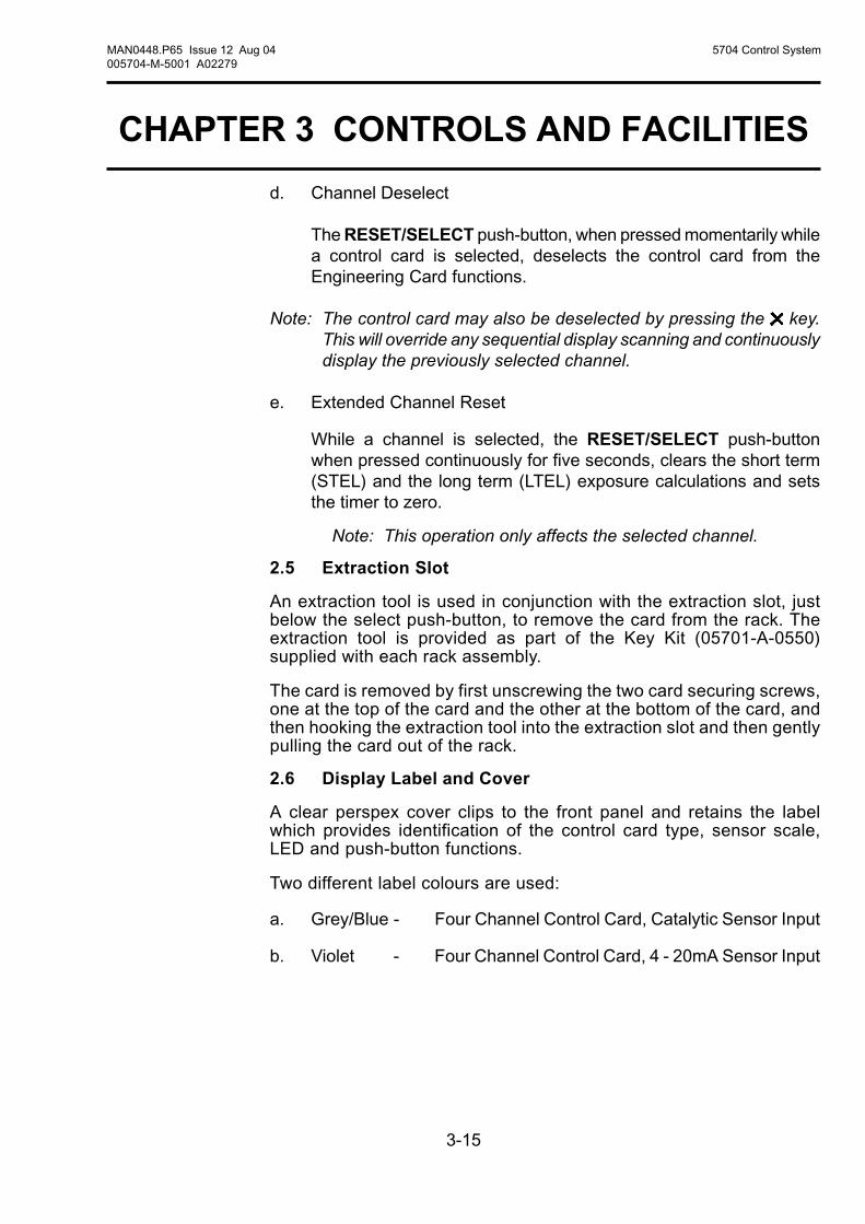
d. Channel Deselect
The RESET/SELECT push-button, when pressed momentarily whilea control card is selected, deselects the control card from theEngineering Card functions.
Note: The control card may also be deselected by pressing the key.This will override any sequential display scanning and continuouslydisplay the previously selected channel.
e. Extended Channel Reset
While a channel is selected, the RESET/SELECT push-buttonwhen pressed continuously for five seconds, clears the short term(STEL) and the long term (LTEL) exposure calculations and setsthe timer to zero.
Note: This operation only affects the selected channel.
2.5 Extraction Slot
An extraction tool is used in conjunction with the extraction slot, justbelow the select push-button, to remove the card from the rack. Theextraction tool is provided as part of the Key Kit (05701-A-0550)supplied with each rack assembly.
The card is removed by first unscrewing the two card securing screws,one at the top of the card and the other at the bottom of the card, andthen hooking the extraction tool into the extraction slot and then gentlypulling the card out of the rack.
2.6 Display Label and Cover
A clear perspex cover clips to the front panel and retains the labelwhich provides identification of the control card type, sensor scale,LED and push-button functions.
Two different label colours are used:
a. Grey/Blue - Four Channel Control Card, Catalytic Sensor Input
b. Violet - Four Channel Control Card, 4 - 20mA Sensor Input

3-16
CHAPTER 3 CONTROLS AND FACILITIES
MAN0448.P65 Issue 12 Aug 04 5704 Control System005704-M-5001 A02279
The perspex cover is removed byfirst removing the control card fromthe rack and then locating a smallhole on the inside of the front paneljust above the LCD display. A bluntobject, such as a screwdriver, is thenpushed through the hole to unclipthe perspex cover.
A small recess in the perspex coverallows a label to be inserted toindicate the channel tag name orgas type.
1234123412341234123412341234
1212
✆✆
Extraction Hole
RESET/SELECT
CHL 4
CHL 3
CHL 2
CHL 1
ATTN
PPM
50
40
30
20
10
0
5704

3-17
MAN0448.P65 Issue 12 Aug 04 5704 Control System005704-M-5001 A02279
CHAPTER 3 CONTROLS AND FACILITIES
3. ENGINEERING CARD
3.1 General
The Engineering Card provides facilities to allow each control cardchannel to be interrogated and to allow normal maintenance functionssuch as calibration to be carried out. It also acts as a connecting pointfor the engineering interface software which allows each card to beconfigured.
3.2 LED Indicators
Two indicators at the top of the front panel of theEngineering Card indicate the operational status ofthe card:
3.2.1 - Green LED
A continuously illuminated LED indicates that thecorrect dc power is connected to the rack via theDC Input Card.
A flashing LED at approximately two secondintervals, indicates a low dc power input level.
A flashing LED at approximately 0.5 secondintervals, indicates a hardware fault.
3.2.2 - Red LED
Provides an indication of the operation of theEngineering Card communications status as follows:
Off: Engineering Card functioning correctly andthe engineering functions are locked.Operators functions are operational to allowthe checking of various control cardchannel settings.
On: Engineering Card functioning correctly andthe engineering functions are unlockedenabling changes to be made to theoperation of a selected control cardchannel.
CLOCKINHIBIT
1ST SPANSPAN
SIGNALZERO
ALARMSBEAD mA

3-18
CHAPTER 3 CONTROLS AND FACILITIES
MAN0448.P65 Issue 12 Aug 04 5704 Control System005704-M-5001 A02279
Flashing: Indicates that a control card has been withdrawn from therack, there is a communications error or that an external PCrunning the engineering interface software is communicatingwith the control cards.
Note: To reset the indication, insert the Engineering Key momentarilyand then remove again.
3.3 Engineering Push-buttons
3.3.1 General
The Engineering Card push-buttons control various functions dependingon the type of control card fitted and whether the Engineering Key isfitted.
3.3.2 Up Push-button ( )
When the up push-button ( ) is operated, it increases the value ofthose functions that can be adjusted. With no engineering functionsselected, this push-button is used to select a particular channel of aselected control card.
3.3.3 Down Push-button ( )
When the down push-button ( ) is operated, it decreases the value ofthose functions that can be adjusted. With no engineering functionsselected, this push-button is used to select a particular channel of aselected control card.
3.3.4 Operation of the Up and Down Push-buttonsSimultaneously
This operation can only be used if a serial printer is connected to therack. When the up ( ) and down ( ) push-buttons are operatedsimultaneously a print out command is selected of the control cardconfiguration and status.
3.3.5 Accept Push-button ( )
When the accept push-button ( ) is operated during any of theengineers functions, this button confirms adjustments that have beenmade and then cancels that function.

3-19
MAN0448.P65 Issue 12 Aug 04 5704 Control System005704-M-5001 A02279
CHAPTER 3 CONTROLS AND FACILITIES
3.3.6 Reject Push-button ( )
When operated during any of the engineers functions and providingthe accept ( ) push-button has not been operated, the reject push-button ( ) cancels adjustments that have been made. This push-button is also used to deselect a selected function and for manualchannel display selections.
3.3.7 BEAD mA Push-button
When the BEAD mA push-button is operated, the display of theselected Catalytic Control Card provides an indication of the selectedchannels sensor head current.
Adjustments to this current can also be made if the Engineering Key isfitted to the Engineering Card.
3.3.8 ALARMS Push-button
When the ALARMS push-button is operated, the display of the selectedcontrol card provides an indication of the selected channels level andtype (rising or falling) of each alarm level (A1, A2, A3), and the STEL/LTEL levels
If the Engineering Key is fitted to the Engineering Card, adjustmentscan be made to the alarm levels, within pre-defined limits, and additionaltest facilities become available. This facility allows each alarm operationto be checked and, if required, its associated output relay to beexercised.
3.3.9 SIGNAL Push-button
When the SIGNAL push-button is operated, the display of the selectedcontrol card provides an indication of the selected channels sensorsignal as follows:
a. 4 - 20mA Control Card - Loop current in mA.
b. Catalytic Control Card - Catalytic bridge output (sensitivity) in mV.
3.3.10 ZERO Push-button
The ZERO push-button can only be used when the Engineering Key isfitted to the Engineering Card and is used to calibrate the zero point ofthe selected control card channel.

3-20
CHAPTER 3 CONTROLS AND FACILITIES
MAN0448.P65 Issue 12 Aug 04 5704 Control System005704-M-5001 A02279
3.3.11 SPAN Push-button
The SPAN push-button can only be used when the Engineering Key isfitted to the Engineering Card and is used to calibrate the span point ofthe selected control card channel.
3.3.12 1ST SPAN Push-button
The 1ST SPAN push-button can only be used when the EngineeringKey is fitted to the Engineering Card and is used to calibrate the spanpoint of a new catalytic sensor fitted to a selected catalytic control cardchannel.
This function is used to provide an indication, in conjunction withsubsequent normal span adjustments, of the output sensitivity of acatalytic sensor and to automatically indicate poisoning or loss ofsensor performance.
3.3.13 CLOCK Push-button
When the CLOCK push-button is operated, the display of the selectedcontrol card provides an indication of the time and date of the rackclock.
The rack clock is located in the Engineering Card, however since theEngineering Card has no display, a control card must be selected toenable the time and date to be displayed. It does not matter whichcontrol card or channel is selected.
If the Engineering Key is fitted to the Engineering Card, the time anddate can be adjusted.
3.3.14 INHIBIT Push-button
When the INHIBIT push-button is operated, the selected control cardchannel is placed in the inhibit mode. This prevents the operation ofany configured relay output alarm functions.
Inhibit can only be used if the Engineering Key is fitted to the EngineeringCard, however, if the Engineering Key is subsequently removed theselected control card channel remains in the inhibit mode.

3-21
MAN0448.P65 Issue 12 Aug 04 5704 Control System005704-M-5001 A02279
CHAPTER 3 CONTROLS AND FACILITIES
3.4 Engineering Serial Port
The Engineering Serial Port is a miniature DIN socket which providesthree functions:
a. Connection point for the Engineering Key to unlock the engineersfunctions.
b. Connection point for the External Engineering Interface which allowseach control card to be configured by an external PC running theengineering interface configuration software.
c. Connection point for a serial printer which can be used to provide ahard copy of the control card configuration data and status.
The Engineering Serial Port and its Engineering Key are shown below:

3-22
CHAPTER 3 CONTROLS AND FACILITIES
MAN0448.P65 Issue 12 Aug 04 5704 Control System005704-M-5001 A02279

4-1
CHAPTER 4 - INSTALLATION INSTRUCTIONS
MAN0448.P65 Issue 12 Aug 04 5704 Control System005704-M-5001 A02279
5704 SERIES
CONTROL SYSTEM
CHAPTER 4
INSTALLATION INSTRUCTIONS
4-2
MAN0448.P65 Issue 12 Aug 04 5704 Control System005704-M-5001 A02279
CHAPTER 4 - INSTALLATION INSTRUCTIONS
WARNING
For installations in the EU, refer to EN60079-14:1997, ‘ElectricalInstallations in Hazardous Areas (other than mines)
Additionally, the code of practice regarding Selection, installation, useand maintenance of apparatus for the detection and measurement ofcombustible gases or oxygen must be complied with. Refer to EN50073.
The above standards apply to the System 57 since the SENSORSmay be installed in potentially hazardous atmospheres.
In addition, appropriate local or national regulations shall be used.”
IMPORTANT NOTICES
1. Zellweger Analytics Limited can take no responsibility for installationand/or use of its equipment if this is not done in accordance withthe appropriate issue and/or amendment of the manual.
2. The user of this manual should ensure that it is appropriate in alldetails to the exact equipment to be installed and/or operated. Ifin doubt, the user should contact Zellweger Analytics Limited foradvice.
3. The System 57 cards contain no user serviceable parts. Refer allservicing to qualified service personnel.
4. When inserting or removing system components ensure that thepower is switched off. Failure to do this may result in damage tothe system.

4-3
CHAPTER 4 - INSTALLATION INSTRUCTIONS
MAN0448.P65 Issue 12 Aug 04 5704 Control System005704-M-5001 A02279
CONTENTSSection Page
1. INTRODUCTION 4-5
2. UNPACKING 4-5
3. LOCATION 4-6
4. CABLING 4-7
5. POWER REQUIREMENTS 4-7
6. VENTILATION 4-9
7. PRELIMINARIES 4-9
8. CABINET INSTALLATION 4-10
9. PANEL INSTALLATION 4-12
10. RACK INSTALLATION 4-14
11. SENSOR INSTALLATION 4-15
11.1 General 4-1511.2 Sensor Line Resistance 4-1611.3 Cable Resistance Guide 4-1711.4 Catalytic Sensors 4-1711.5 4 - 20mA Loop Powered Sensors 4-1811.6 4 - 20mA Transmitters 4-18
12. SENSOR CONNECTIONS 4-19
12.1 General 4-1912.2 Catalytic Sensor Connections 4-1912.3 4 - 20mA Loop Powered Sensor Connections 4-2312.4 4 - 20mA Transmitter Connections 4-2512.5 IS Series 2000 Toxic Transmitter Connections 4-39
13. OUTPUT CONNECTIONS 4-41
13.1 Relay Output 4-4113.2 Analogue Output 4-42
14. REMOTE INPUT CONNECTIONS 4-4715. DC POWER CONNECTIONS 4-49

4-4
MAN0448.P65 Issue 12 Aug 04 5704 Control System005704-M-5001 A02279
CHAPTER 4 - INSTALLATION INSTRUCTIONS
15.1 General 4-4915.2 Individually Powered Control Cards 4-50
16. AC TO DC POWER SUPPLY UNIT CONNECTIONS 4-51
17. UPGRADING THE AC TO DC POWER SUPPLY UNITS 4-53
17.1 General 4-5317.2 8-Way and 16-Way AC to DC Power Supply Unit
Upgrade to 100W 4-5617.3 16-Way AC to DC Power Supply Unit Upgrade
to 150W or 200W 4-57

4-5
CHAPTER 4 - INSTALLATION INSTRUCTIONS
MAN0448.P65 Issue 12 Aug 04 5704 Control System005704-M-5001 A02279
1. INTRODUCTION
A summary of the System 57 controller installation procedures is shownbelow:
a. Unpack and check the equipment.
b. Identify a suitable location and check the cabling requirements.
c. Confirm the power supply requirements.
d. Install the Cabinet, 19" Mounting Frame or Panel Cutout as required.
e. Fit the System 57 rack into the Cabinet, 19" Mounting Frame or PanelCutout.
f. Install the sensors and wire back to the System 57.
g. Check, and if necessary reconfigure, the Four Channel Control Cards.
h. Wire the sensors to the Quad Relay Interface Card terminal blocks.
i. Wire the outputs from the Quad Relay Interface Card terminal blocksor from the Relay Interface Assembly if used.
j. Wire the power supply to the DC Input Card.
k. In individually powered applications, wire the power supply to eachQuad Relay Interface Card.
After installation is complete perform the commissioning proceduresoutlined in Chapter 5.
The following sections of this chapter provide a detailed explanation ofthe installation operations.
2. UNPACKING
On receipt:
a. Carefully unpack the equipment observing any instructions printed onor contained in the packaging.

4-6
MAN0448.P65 Issue 12 Aug 04 5704 Control System005704-M-5001 A02279
CHAPTER 4 - INSTALLATION INSTRUCTIONS
b. Check the contents for transit damage and against the packing notefor deficiencies.
c. Locate the configuration sheet supplied with the unit and confirm thateach channel card type and settings are compatible with the proposedsensors.
3. LOCATION
The control system must be installed in a safe area such as a control orequipment room, away from sources of heat, with adequate ventilationand protected from the weather.
There are two different System 57 rack configurations to accommodateeither front or rear field wiring entry. Each configuration is available in halfor full 19" width. The three most common mounting methods are:
a. 19" Mounting Frame
The System 57 19" 6U front and 3U rear access racks are compatiblewith the standard 19" (483mm) sub-rack format and may therefore befitted into any suitable 19" mounting frame.
b. Cabinet
Wall mounting cabinets are available in two sizes to accommodatethe 19" and half 19" 6U front access rack assemblies.
c. Panel
Alternatively all the racks are suitable for fitting directly into a panelcutout aperture.
Power supply units are available, in both 19" and half 19" 1U formats, forapplications where an ac input power source is to be used. It isrecommended that the power supply units are mounted directly abovethe System 57 rack.
CAUTION
3U rear access racks should always be supported at the rear ofthe unit to prevent distortion and excessive loading of the frontflange plates.

4-7
CHAPTER 4 - INSTALLATION INSTRUCTIONS
MAN0448.P65 Issue 12 Aug 04 5704 Control System005704-M-5001 A02279
4. CABLING
The field terminals on the Quad Relay Interface and Relay InterfaceAssembly accept single or multi-stranded wire up to 2.5mm˝ (14 AWG).Cables should be routed carefully to avoid physical and environmentalhazards such as mechanical stress and high temperatures.
Sensor wiring should consist of a cable with an earthed outer shield andshould be routed away from sources of interference such as ac powercables, motors, machinery etc. All sensor cabling is subject to a maximumcable length that is dependant upon the cable line resistance and sensortypes.
The current ratings of the power and relay cables should always behigher than the worst case maximum load requirement.
All sensor field cables must be screened in order to ensure correctoperation of the system and to meet European Standards for RFI andEMC. The cable screen of each sensor should be connected to aGROUND terminal at the cabinet entry or the ground terminal of theappropriate Quad Relay Interface Card or another suitable ground point.
5. POWER REQUIREMENTS
The System 57 operates from a nominal 24V (18V to 32V) dc powersupply input which may be derived from various sources including themains ac, via a separate ac to dc power supply unit, local plant dc supplyand/or battery backup dc supply.
The power supply may be applied to the System 57 backplane, via theDC Input Card, where the maximum backplane current is limited to 8A.The DC Input Card terminal blocks allow flexible power connections anddiode isolation for two separate power supply inputs.
Where the number of Four Channel Control Cards fitted and the type ofsensors used would cause a backplane current in excess of the 8Amaximum, it is necessary to connect the power supply to each individualcontrol card via its Quad Relay Interface Card. As a general rule,individually powered cards are required where more than eight catalyticcontrol cards are fitted.
See Section 17 for connection details.
The power supply rating required is dependent upon the sensor types,number of channels and configuration of the System 57. Table 1, thePower Budget Calculation Sheet, allows for a quick and easy calculationof the worst case power requirement for the system. In many cases alower power rating can be used, however, a more detailed power budgetanalysis should be performed to confirm the exact requirement.

4-8
MAN0448.P65 Issue 12 Aug 04 5704 Control System005704-M-5001 A02279
CHAPTER 4 - INSTALLATION INSTRUCTIONS
Table 1 Power Budget Calculation SheetTo calculate the power requirement:(1) Enter the number of devices of each type used in the system in column B.(2) Multiply by the unit power shown in column C.(3) Enter the result in column D.(4) Add up column D to calculate the total power required.
Device or Sensor Type Number Unit Totalin Rack Requirement Power
(W) (W)
A B x C = DSystem 57 DEVICES:
Four Channel Control Card,Catalytic (includes bridge driveat 200mA) ____ 12.8 ____Four Channel Control Card,4 - 20mA (includes loop power) ____ 8.3 ____Engineering Card 1 1.5 1.5DC Input Card 1 0 0Modbus Interface 232 ____ 0.75 ____Modbus Interface 422/485 ____ 1.50 ____Event Printing ____ 0.75 ____Alarm Update ____ 0.25 ____Update Panel ____ 0.20 ____Quad Relay Interface Card* ____ 1.7 ____Relay Interface Assembly* ____ 6.5 ____Analogue Output Modules (4 off)(includes loop power) ____ 4.0 ____
Allowance for Transmitters & Sensorspowered from System 57 PSU:Searchline ____ 5.0 ____Searchline Excel Receiver ____ 8.0 ____Searchline Excel Transmitter (S/R) ____ 6.5 ____Searchline Excel Transmitter (L/R) ____ 7.5 ____Searchline Excel Cross Duct TX & RX ____ 13.0 ____Searchpoint 500 ____ 10.0 ____Searchpoint Optima ____ 4.2 ____Searchpoint Optima plus ____ 4.5 ____Series 2000 Toxic ____ 0 0Series 2000 Combustible(incl UL) ____ 3.8 ____Digi-Chem ____ 0.6 ____Digi-Cat (includes sensor) ____ 2.0 ____Digi-Ana Toxic ____ 0.6Digi-Optima ____ 4.80 ____Life Line ____ 0 ____Others (refer to manufacturersdata for column (C) ____ x ____Apex Toxic* 4.0Apex Combustible* 5.5Opus/Lifeline II Toxic* 2.4Opus/Lifeline II Combustible* 2.9
TOTAL SYSTEM POWER REQUIREMENT = W
* All relays energised.

4-9
CHAPTER 4 - INSTALLATION INSTRUCTIONS
MAN0448.P65 Issue 12 Aug 04 5704 Control System005704-M-5001 A02279
The 8-Way AC to DC Power Supply Units can provide a 50W dc supplyor a 100W dc supply depending upon whether one or two switch modemodules are incorporated in the power supply unit.
Similarly, the 16-Way AC to DC Power Supply Units can provide a 50W,100W, 150W and 200W dc supplies depending upon whether one, two,three or four switch mode modules are incorporated in the power supplyunit.
6. VENTILATION
The 5704 Control System provides the facility for a large number ofchannels in a very small space. In heavily populated racks, especiallythose with many catalytic input control cards or relays configured fornormally energised operation, it is possible for the heat dissipation tocause a significant rise in temperature both within the rack and in an areaclose to the rack.
As such, careful consideration must be given to thermal planning. Toachieve most from the convection cooling, always ensure that the air canflow freely through the rack and power supply. Do not obstruct the air ventholes in the top and bottom of the rack and if possible space the controlcards evenly within the rack.
It is recommended that during commissioning the operating temperatureof the rack is checked to ensure that the maximum operating temperatureof 55oC is not exceeded. In some cases the addition of forced airventilation may be required.
Maximum power supply configuration allowed without provision foradditional ventilation is 100w for 8 way cabinet and 200w for 16 waycabinet.
7. PRELIMINARIES
Ensure that each control card is compatible with the proposed sensor/transmitter to be connected to that control card.
Ensure that where an AC to DC Power Supply Unit is to be used, this iscompatible with the local mains ac supply voltage and that the PSUpower rating is adequate for its individual system load.
Note: The model 05701-A-0405 and 05701-A-0406 AC to DC PowerSupply Units operate, without the requirement of input voltageadjustments, from an 85V to 264V, 47Hz to 440Hz ac supplyinputs.

4-10
MAN0448.P65 Issue 12 Aug 04 5704 Control System005704-M-5001 A02279
CHAPTER 4 - INSTALLATION INSTRUCTIONS
8. CABINET INSTALLATION
Two cabinets are available, an 8-way to accommodate the 8-way frontaccess rack and a 16-way to accommodate the 16-way front accessrack.
The cabinet must be secured to a wall, or other suitable vertical surface,as follows:
(1) Knock out the bottom gland-plate entries as appropriate for thesystem cabling and fit the glands before mounting the cabinet.
(2) Attach the four mounting brackets provided to the cabinet.
(3) Using the dimensions shown mark the position of the mounting holeson the mounting surface.
(4) Drill and wall plug the mounting holes as necessary.
Note: The mounting brackets will accept up to a 10mm ( 0.4'' ) diameterscrew.
(5) Secure the cabinet in position using appropriate mounting screws.
(6) Fit the System 57 Rack and AC to DC Power Supply Unit (if required)into the cabinet in the positions as shown:
(7) Pass cables through the gland adjacent to field terminal blocks,where possible keeping the sensor cable(s) separate from the otherwiring.
(8) Prepare and connect the cable ends to Quad Relay Interface andExpansion Relay Card terminals. For terminal identification see Chapter2.
(9) Ensure that the cabinet is properly earthed by connecting a suitableearth cable to the earth stud located in the bottom panel of thecabinet.
(10) Close and lock the cabinet.
CAUTION
Do not apply power to the System 57 until the commissioningprocedure has been read and understood. See Section 5.

4-11
CHAPTER 4 - INSTALLATION INSTRUCTIONS
MAN0448.P65 Issue 12 Aug 04 5704 Control System005704-M-5001 A02279
Wall Mounting Bracket Hole Locations Cabinet Mounting Brackets
630
8 way 33716 way 540
All dimension shown in mm.
268
Cabinet Dimensions:
9
10.2
36
9
27
15
10
100
15
100
430
8 way 36716 way 57
15
All dimension shown in mm.

4-12
MAN0448.P65 Issue 12 Aug 04 5704 Control System005704-M-5001 A02279
CHAPTER 4 - INSTALLATION INSTRUCTIONS
9. PANEL INSTALLATION
All racks and the AC to DC Power Supply Units are suitable for panelinstallation and are installed as follows:
(1) Cut out a suitable aperture to accommodate the System 57 rack andpower supply unit (where required) using the dimensions shown:
Eight Card Cabinet Installation
BlankingPanel
Control Cards
Interface/Relay Cards
8-Way AC to DCPower Supply Unit
Engineering Card
DC Input Card
Accessory Plate(suitable for mounting
DIN rails, circuitbreakers, relays, etc.)
16 Card Cabinet Installation
Blanking Panel
Control Cards
Interface/RelayCards
16-Way AC to DCPower Supply Unit
Engineering Card
DC Input Card
Accessory Plate(suitable for mounting
DIN rails, circuitbreakers, relays, etc.)

4-13
CHAPTER 4 - INSTALLATION INSTRUCTIONS
MAN0448.P65 Issue 12 Aug 04 5704 Control System005704-M-5001 A02279
Rack Assembly A B C D E Depth
8 Way Rear Access 279.4 261.9 57.0 37.8 132.5 287.6
8 Way Front Access 279.4 261.9 190.5 37.8 266.0 217.6
16 Way Rear Access 482.6 465.1 57.0 37.8 132.5 287.6
16 Way Front Access 482.6 465.1 190.5 37.8 266.0 217.6
Panel Cut-out Clearance
8 Way Width: 247 Height as column E16 Way 450 as column E
A
B
C E
D
(holes 6mmdiameter)
Rack Table of Sizes (mm)
A
B
C E
D
(holes 6mmdiameter)

4-14
MAN0448.P65 Issue 12 Aug 04 5704 Control System005704-M-5001 A02279
CHAPTER 4 - INSTALLATION INSTRUCTIONS
AC to DC PSU Table of Sizes (mm)
PSU Assembly A B Clearance
Width Height Depth
8 Way 279.4 261.9 222 41 190
16 Way 482.6 465.1 443 41 190
(2) Insert the rack into the aperture and secure using M6, or similar bolts,through the four mounting holes located upon the front flange plates.
(3) Ensure adequate support at the rear of rear access racks.
(4) Prepare and connect the cable ends to Quad Relay Interface andExpansion Relay Cards terminals. For terminal identification seeChapter 2. Where possible keep sensor cables separate from theother wiring.
(5) Ensure that the rack is properly earthed by connecting a suitableearth cable to the earth stud located at the rear of the rack.
CAUTION
Do not apply power to the System 57 until the commissioningprocedure has been read and understood. See Chapter 5.
10. RACK INSTALLATION
The 16-way 3U high rear access and 6U high front access racks aresuitable for mounting in standard 19" (483mm) wide Mounting Frames.These are fitted as follows:
A
31.8
5.9
43.6
8.4 B

4-15
CHAPTER 4 - INSTALLATION INSTRUCTIONS
MAN0448.P65 Issue 12 Aug 04 5704 Control System005704-M-5001 A02279
(1) Insert the rack into the 19" Mounting Frame and secure using M6 orsimilar bolts through the four mounting holes located on the frontflange plates.
(2) Ensure adequate support at the rear of rear access racks.
(3) Prepare and connect the cable ends to Quad Relay Interface andExpansion Relay Card terminals. For terminal identification seeChapter 2. Where possible keep sensor cables separate from theother wiring.
(4) Ensure that the rack is properly earthed by connecting a suitableearth cable to the earth stud located at the rear of the rack.
CAUTION
Do not apply power to the System 57 until the commissioningprocedure has been read and understood. See Chapter 5.
11. SENSOR INSTALLATION
11.1 General
Always install the sensors in accordance with the Sensor OperatingInstructions.
In general, sensors for lighter than air gasses should be located at a highlevel and sensors for heavier than air gasses should be located at a lowlevel.
Do not install the sensors:
a. Where the normal air flow may be impeded.
b. In corners of rooms where static air pockets may exist.
c. Near sources of heat such as convector heaters.
Do install the sensors:
a. As close as possible to the potential source of gas to be detected inorder to give the maximum possible warning.
b. So that they are accessible for maintenance work.

4-16
MAN0448.P65 Issue 12 Aug 04 5704 Control System005704-M-5001 A02279
CHAPTER 4 - INSTALLATION INSTRUCTIONS
11.2 Sensor Line ResistanceSensors should be located such that the line resistance of cable doesnot exceed the maximum permitted. The table below gives a quickguide to the maximum cable lengths permitted for specific sensors,when connected by stranded copper conductor cables of various sizesto a System 57 running at the minimum dc input voltage.
Maximum Cable Length (m)
Device or Sensor Type Conductor Cross Sectional Area
AWG 21 19 18 16 14mm˝ 0.50 0.75 1.00 1.50 2.50
704/705 500 750 1000 1500 2500780 (at 200mA bridge current) 500 750 1000 1500 2500811 5600 8400 11200 16800 28000910 (Single pair at 200mA) 480 720 960 1400 2400910 (2 pair at 200mA) 230 340 460 690 1100911 5600 8400 11200 16800 28000SensePoint Flam. LEL/ppm 500 750 1000 1500 2500SensePoint Toxic 3200 4800 6400 9600 16000SignalPoint Flamable 500 750 1000 1500 2500SignalPoint Toxic 2000 3000 4000 6000 10000Digi-Cat 400 570 800 1150 1850Digi-Chem 1000 1500 2000 3100 4800Digi-Ana 1000 1500 2000 3100 4800Digi-Optima 180 260 360 540 860Life Line 3200 4600 6500 9750 15000Searchline(minimum dc supply 21V) 60 90 120 180 300Searchpoint 500 32 48 64 96 160Searchpoint OPTIMA(minimum dc supply 19V) 180 270 360 540 900Series 2000 Flammable 450 670 900 1300 2200Series 2000 Toxic 1600 2400 3200 4800 8000Searchline Excel Receiver(Minimum dc supply 21V) 90 135 179 271 449Searchline Excel Transmitter(S/R) (Minimum dc supply 21V) 141 211 282 425 704Searchline Excel Transmitter(L/R) (Minimum dc supply 21V) 94 141 188 283 998Searchline Excel Cross DuctTransceiver assembly(Minimum dc supply 21V) 55 82 109 165 274Searchpoint Optima Plus 159 237 315 476 787Apex - Toxic 180 270 360 540 900Apex - Combustible/Thick Film 130 195 260 390 650Opus/LLII - Toxic 300 450 600 900 1500Opus/LLII - Combustible 250 375 500 750 1250
The figures in the table above provide a useful reference guide tomaximum cable lengths, however, in many circumstances longer cableruns can be used. eg. Where the dc input voltage is higher than theminimum. In these circumstances a more detailed analysis is requiredto determine maximum line resistance.
WARNINGIt is required that verification by testing that cable faults (open circuit andshort circuit) at the transmitter’s side are correctly detected by the controlcard. The control card shall indicate ER81, ER87 or ER88 in this case.
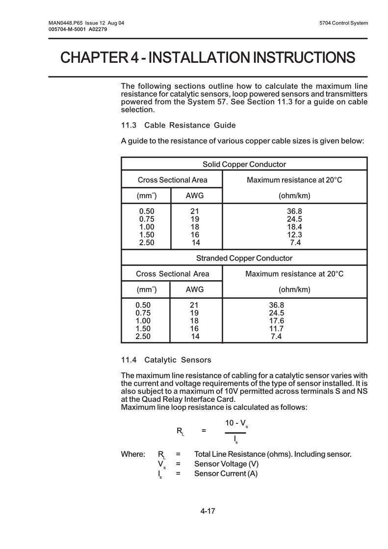
4-17
CHAPTER 4 - INSTALLATION INSTRUCTIONS
MAN0448.P65 Issue 12 Aug 04 5704 Control System005704-M-5001 A02279
The following sections outline how to calculate the maximum lineresistance for catalytic sensors, loop powered sensors and transmitterspowered from the System 57. See Section 11.3 for a guide on cableselection.
11.3 Cable Resistance Guide
A guide to the resistance of various copper cable sizes is given below:
Solid Copper Conductor
Cross Sectional Area Maximum resistance at 20°C
(mm˝) AWG (ohm/km)
0.50 21 36.80.75 19 24.51.00 18 18.41.50 16 12.32.50 14 7.4
Stranded Copper Conductor
Cross Sectional Area Maximum resistance at 20°C
(mm˝) AWG (ohm/km)
0.50 21 36.80.75 19 24.51.00 18 17.61.50 16 11.72.50 14 7.4
11.4 Catalytic Sensors
The maximum line resistance of cabling for a catalytic sensor varies withthe current and voltage requirements of the type of sensor installed. It isalso subject to a maximum of 10V permitted across terminals S and NSat the Quad Relay Interface Card.Maximum line loop resistance is calculated as follows:
10 - VsRL =
Is
Where: RL = Total Line Resistance (ohms). Including sensor.Vs = Sensor Voltage (V)Is = Sensor Current (A)

4-18
MAN0448.P65 Issue 12 Aug 04 5704 Control System005704-M-5001 A02279
CHAPTER 4 - INSTALLATION INSTRUCTIONS
11.5 4 - 20mA Loop Powered Sensors:
The maximum line resistance of cabling for a 4 - 20mA loop poweredsensor varies with the voltage drive requirements of the type of sensorinstalled. It is also subject to a 24V maximum loop drive voltage.
Maximum line loop resistance is calculated as follows:
24 - VsRL =
0.025
Where: RL = Total Line Resistance (ohms)Vs = Minimum Sensor Operating Voltage (V)
11.6 4 - 20mA Transmitters
The maximum line resistance of cabling for a 4 - 20mA transmitterpowered from the System 57 varies with the voltage and currentrequirements of the transmitter. It is also subject to the minimum supplyvoltage available from the System 57.
Maximum line loop resistance is calculated as follows:
Vr - VsRL =
Is
Where: RL = Total Line Resistance (ohms)Vr = Minimum DC Supply to System 57 (V)Vs = Sensor Voltage (V)Is = Sensor Current (A)
Making the above calculation using a Vr of 18V will accommodate theworst case low dc supply situation.
The maximum resistance per core can be calculated from the aboveconfigurations as follows:
RL
Maximum Resistance of Core = ohms2

4-19
CHAPTER 4 - INSTALLATION INSTRUCTIONS
MAN0448.P65 Issue 12 Aug 04 5704 Control System005704-M-5001 A02279
12. SENSOR CONNECTIONS
12.1 General
WARNING
Incorrect connection of the sensor wires may cause damage toboth the sensor and System 57.
CAUTION
The sensors connections must always be made with the System57 unit in an unpowered state. Isolate power supplies at theirsource before making connections.
Ensure that any external dc backup battery supply is alsodisabled.
IMPORTANT
In order to ensure the correct operation of the system and tomeet European Standards for RFI and EMC, all sensor field cablesmust be screened. The cable screen of each sensor should beconnected to the cabinet protective earth.
Connect the cabling to sensors in accordance with the Sensor OperatingInstructions and run the field cables back to the System 57 unit. Thesensor cables should be routed away from sources of interference suchas ac power cables, motors, machinery etc.
Use the information on the configuration sheet provided with the unit todecide which sensor to connect to each channel. The following sectionsdescribe the sensor connections for the Catalytic and 4 - 20mA inputFour Channel Control Cards.
12.2 Catalytic Sensor Connections
Catalytic sensors require a three wire connection and the sensordocumentation will indicate three connections S, 01 and NS, which areusually brown, white and blue respectively.
At the System 57 end of the field cable, the three sensor wires shouldeach be connected to the respective matching S, 01 or NS terminal of theappropriate channel on the Quad Relay Interface Card that is attached tothe required Four Channel Control Card.

4-20
MAN0448.P65 Issue 12 Aug 04 5704 Control System005704-M-5001 A02279
CHAPTER 4 - INSTALLATION INSTRUCTIONS
The sensor cable screen or steel wire armour (or braid), as appropriate,should be connected to the system (protective) earth. This can beachieved where the cable enters the cabinet by using a metal cablegland, or by other suitable means, and avoiding any screen 'tails'within the cabinet.
Where the cable consists of a separate screen sheath and wire armour(or braid), the armour should be connected, at the cabinet entry, to theprotective earth and the screen sheath should be connected to theGROUND terminal of the Quad Relay Interface Card or to a suitableinstrument earth point.

4-21
CHAPTER 4 - INSTALLATION INSTRUCTIONS
MAN0448.P65 Issue 12 Aug 04 5704 Control System005704-M-5001 A02279
Notes: 1. Where a sensor is earthed locally, either to an Earth Stud orthrough the sensor casing or mounting, to avoid earth loopsthe screen sheath of the cable should only be connected atone end.
2. The above diagram shows the sensor connections for Channel1. Channels 2, 3 and 4 connections are similar and their pinconnection numbers are shown below:
Channel Sensor Connection
S 01 NS Ground
Quad Relay 1 15 17 19 13Interface Connections 2 16 18 20 14
3 21 23 25 134 22 24 26 14
Combustible Sensor, Junction Box and Terminal BlockConnections
NS
BrownWhiteBlue
GND
S
01
NS
Junction BoxTerminal
BlockJunctionBox
Quad Relay Interface Card05704-A-0121
Screened/Armoured Cable
Earth Terminal
780 Series910 704/705980 Sensors
Cabinet
ProtectiveEarth
Separate Screen Sheath(If Fitted)
13151719
S01
Green/Yellow

4-22
MAN0448.P65 Issue 12 Aug 04 5704 Control System005704-M-5001 A02279
CHAPTER 4 - INSTALLATION INSTRUCTIONS
Channel Sensor Connection
S 01 NS Ground
Quad Relay 1 15 17 19 13Interface Connections 2 16 18 20 14
3 21 23 25 134 22 24 26 14
SensePoint Combustible Sensor, Junction Box and TerminalBlock Connections
35 36
33 34
31 32
29 30
27 28
25 26
23 24
21 22
19 20
17 18
15 16
13 14
11 12
9 10
7 8
5 6
3 4
1 2
Quad Relay Interface Card05704-A-0121
Separate Screen Sheath(If Fitted)
Screened/Armoured Cable
Cabinet
13
151719NS
GND
S01
ProtectiveEarth
JunctionBox
Brown
Green/Yellow
SensePointCombustible LEL
White
Blue
Junction BoxTerminal Block
01S
NS
Notes: 1. Where a sensor is earthed locally, either toan Earth Stud or through the sensor casing ormounting, to avoid earth loops the screensheath of the cable should only be connectedat one end.
2. The above diagram shows the sensorconnections for Channel 1. Channels 2, 3and 4 connections are similar and their pinconnection numbers are shown below:

4-23
CHAPTER 4 - INSTALLATION INSTRUCTIONS
MAN0448.P65 Issue 12 Aug 04 5704 Control System005704-M-5001 A02279
12.3 4 - 20mA Loop Powered Sensor Connections
Loop powered sensors require a two wire connection and the sensordocumentation will indicate the positive and negative loop connections,usually brown and blue respectively.
At the System 57 end of the field cable the two sensor wires should beconnected to the S (positive) and 01 (negative) terminals of theappropriate channel on the Quad Relay Interface Card that is attached tothe required Four Channel Control Card.
The sensor cable screen or steel wire armour (or braid), as appropriate,should be connected to the system (protective) earth. This can be achievedwhere the cable enters the cabinet by using a metal cable gland, or byother suitable means, and avoiding any screen 'tails' within the cabinet.
Where the cable consists of a separate screen sheath and wire armour(or braid), the armour should be connected, at the cabinet entry, to theprotective earth and the screen sheath should be connected to theGROUND terminal of the Quad Relay Interface Card or to a suitableinstrument earth point.

4-24
MAN0448.P65 Issue 12 Aug 04 5704 Control System005704-M-5001 A02279
CHAPTER 4 - INSTALLATION INSTRUCTIONS
Channel Sensor Connection
S 01
Quad Relay 1 15 17Interface Connections 2 16 18
3 21 234 22 24
Loop Powered Sensor (Measuring Resistance in Supply Return)
Notes: 1. Where a sensor is earthed locally, either to an Earth Stud or through the sensorcasing or mounting, to avoid earth loops the screen sheath of the cable should onlybe connected at one end.
2. The above diagram shows the sensor connections for Channel 1. Channels 2, 3and 4 connections are similar and their pin connection numbers are shown below:
JunctionBox
RedRed
Green/Yellow
SensorScreen
SensePointToxic Sensor
SignalPointToxic Sensor
BlueBlue
S01Screen
Junction BoxTerminal Block
01
S
-+
Quad Relay Interface Card05704-A-0121
S
01-+
Arrows IndicateDirection of Loop
Current Flow
ScreenedCable
Earth Terminal811, 911 ECC,S2000 Toxic
Sensor
15
17
BrownBlue
Junction BoxTerminal BlockJunction
Box
Green/Yellow
Cabinet
ProtectiveEarth
S01

4-25
CHAPTER 4 - INSTALLATION INSTRUCTIONS
MAN0448.P65 Issue 12 Aug 04 5704 Control System005704-M-5001 A02279
12.4 4 - 20mA Transmitter Connections
Transmitters require either three or four wire connections and the sensordocumentation will indicate the 0V and +24V power connections and thepositive and negative loop connections.
At the System 57 end of the field cable the sensor loop signal wiresshould be connected to the S, 01, NS terminals on the Quad RelayInterface Card that is attached to the required Four Channel ControlCard. The exact terminals used vary depending upon whether three orfour wire topology is used, the requirement for a loop current sourceconfiguration and the channel to be connected to.
The transmitter power connection +24V and 0V should be connected toa suitable dc supply.
Note: Terminals 35 and 36 on the Relay Interface Card are inputterminals only and cannot be used to power the transmitter.
The sensor cable screen or steel wire armour (or braid), as appropriate,should be connected to the system (protective) earth. This can be achievedwhere the cable enters the cabinet by using a metal cable gland, or byother suitable means, and avoiding any screen 'tails' within the cabinet.
Where the cable consists of a separate screen sheath and wire armour(or braid), the armour should be connected, at the cabinet entry, to theprotective earth and the screen sheath should be connected to theGROUND terminal of the Quad Relay Interface Card or to a suitableinstrument earth point.

4-26
MAN0448.P65 Issue 12 Aug 04 5704 Control System005704-M-5001 A02279
CHAPTER 4 - INSTALLATION INSTRUCTIONS
Notes: 1. Where the sensor is earthed locally, either to the stud orthrough the sensor casing or mounting, to avoid earth loopsthe screen sheath should only be connected at one end, i.e.the sensor or at the relay/interface card.
2. The above diagram shows the sensor connections for Channel1. Channels 2, 3 and 4 connections are similar and their pinconnection numbers are shown below:
Channel Sensor Connection
01 NS
Quad Relay 1 17 19Interface Connections 2 18 20
3 23 254 24 26
Three Wire Control Card Current Sink, Transmitter CurrentSource Connection for Opus/Lifeline II
(Signal Returned to 0V)
ScreenedCable
Arrows IndicateDirection of Loop
Current Flow
01
NS
Quad Relay Interface Card05704-A-0121
Opus/Lifeline II Transmitter
1719
Screen tocable gland
Cabinet
ProtectiveEarth
+24V*
0V*
* 24V supply may be obtainedfrom either the cabinet or aseparate field supply
J4
J5
1 3
6

4-27
CHAPTER 4 - INSTALLATION INSTRUCTIONS
MAN0448.P65 Issue 12 Aug 04 5704 Control System005704-M-5001 A02279
Notes: 1. Where the sensor is earthed locally, either to the stud orthrough the sensor casing or mounting, to avoid earth loopsthe screen sheath should only be connected at one end, i.e.the sensor or at the relay/interface card.
2. The above diagram shows the sensor connections forChannel 1. Channels 2, 3 and 4 connections are similar andtheir pin connection numbers are shown below:
Channel Transmitter Connection
S 01
Quad Relay 1 15 17Interface Connections 2 16 18
3 21 234 22 24
Four Wire Isolated Signal Input, Transmitter Connection forOpus/Lifeline II
S
01
ScreenedCable
Quad Relay Interface Card05704-A-0121
15
17
Cabinet
ProtectiveEarth
+24V*
0V*
Opus/Lifeline II Transmitter
* 24V supply may be obtainedfrom either the cabinet or aseparate field supply
Arrows IndicateDirection of Loop
Current Flow
56
Screen tocable gland
1 3
J4
J5

4-28
MAN0448.P65 Issue 12 Aug 04 5704 Control System005704-M-5001 A02279
CHAPTER 4 - INSTALLATION INSTRUCTIONS
Apex LinkSettings:
SK4(Comms
andPower)
Apex
1234567
Channel Transmitter Connection
01 NS
Quad Relay 1 17 19Interface Connections 2 18 20
3 23 254 24 26
Three Wire Control Card Current Sink, Transmitter Current SourceConnection for Apex (Signal Returned to 0V Supply)
Notes: 1. The Apex Transmitter should be earthed locally. The transmitter is earthed throughthe Earth Stud, to avoid earth loops the screen sheath of the cable should only beconnected at the transmitter.
2. The above diagram shows the sensor connections for Channel 1. Channels 2, 3and 4 connections are similar and their pin connection numbers are shown below:
Arrows Indicate Direction ofLoop Current Flow
+24V
4 - 20mA(-)
0V
Apex Transmitter
ScreenedCable
01
NS
Quad Relay Interface Card05704-A-0121
1719
Cabinet
ProtectiveEarth
+24V*
0V*
* 24V supply may be obtainedfrom either the cabinet or aseparate field supply
J4
J5

4-29
CHAPTER 4 - INSTALLATION INSTRUCTIONS
MAN0448.P65 Issue 12 Aug 04 5704 Control System005704-M-5001 A02279
Note: 1. The Apex Transmitter should be earthed locally. The transmitteris earthed through the Earth Stud, to avoid earth loops thescreen sheath of the cable should only be connected at thetransmitter.
2. The above diagram shows the sensor connections for Channel 1.Channels 2, 3 and 4 connections are similar and their pinconnection numbers are shown below:
Channel Transmitter Connection
S 01
Quad Relay 1 15 17Interface Connections 2 16 18
3 21 234 22 24
Four Wire Isolated Signal Input, Transmitter Connection for Apex
S
01
ScreenedCable
Arrows IndicateDirection of Loop
Current Flow
+24V
4 - 20mA(-)
4 - 20mA(+)
0V
Quad Relay Interface Card05704-A-0121
15
17
Cabinet
ProtectiveEarth
+24V*
0V*
Apex Transmitter
SK4(Comms
andPower)
Apex
1234567
Apex LinkSettings:
J4
J5
* 24V supply may be obtainedfrom either the cabinet or aseparate field supply

4-30
MAN0448.P65 Issue 12 Aug 04 5704 Control System005704-M-5001 A02279
CHAPTER 4 - INSTALLATION INSTRUCTIONS
Notes: 1. Where a sensor is earthed locally, either to an Earth Stud orthrough the sensor casing or mounting, to avoid earth loopsthe screen sheath of the cable should only be connected atone end.
2. The above diagram shows the sensor connections for Channel1. Channels 2, 3 and 4 connections are similar and their pinconnection numbers are shown below:
Channel Sensor Connection
01 NS
Quad Relay 1 17 19Interface Connections 2 18 20
3 23 254 24 26
Three Wire Control Card Current Sink, Transmitter CurrentSource Connection for Series 2000 Flammable
(Signal Returned to 0V)
ScreenedCable
Arrows IndicateDirection of Loop
Current Flow
01
NS
Quad Relay Interface Card05704-A-0121
Earth Stud
+24V
4 - 20mA (-)
0V
GND
Series 2000Flammable
1719
11
4923
Link fitted forTransmitter Source
Cabinet
ProtectiveEarth
+24V*
0V*
* 24V supply may be obtainedfrom either the cabinet or aseparate field supply

4-31
CHAPTER 4 - INSTALLATION INSTRUCTIONS
MAN0448.P65 Issue 12 Aug 04 5704 Control System005704-M-5001 A02279
4
4
1
1
GND
ORANGE A
+24V DC Supply
BLACK 0V
WHITE 4-20mA
BLUE B
0V DC Supply
4-20mA Output
GRN/YEL GND
RED 24V
+24V*
0V*
35 36
33 34
31 32
29 30
27 28
25 26
23 24
21 22
19 20
17 18
15 16
13 14
11 12
9 10
7 8
5 6
3 4
1 2
Quad Relay Interface Card05704-A-0121
Arrows IndicateDirection of LoopCurrent Flow
Screened Cable
* 24V supply may be obtained from eitherthe cabinet or a separate field supply
CabinetField Connections
28
1917
NS01
ProtectiveEarth(Instrumentor CleanEarth)
Searchline Excel ReceiverCurrent Source
Connections using aDVC100 Junction Box
Notes: 1. Where a sensor is earthed locally, either to an Earth Stud orthrough the sensor casing or mounting, to avoid earth loopsthe screen sheath of the cable should only be connected atone end.
2. The above diagram shows the sensor connections for Channel1. Channels 2, 3 and 4 connections are similar and their pinconnection numbers are shown below:
Channel Sensor Connection
01 NS
Quad Relay 1 17 19Interface Connections 2 18 20
3 23 254 24 26
Three Wire Control Card Current Sink, Transmitter CurrentSource Connection for Searchline Excel
(Signal Returned to 0V)
Receiver Connections
1
4TB2
TB14
1
EarthTerminal
Earth
Instrument Earth
CableShield
ORANGE A
0V DC Supply Rx (0V)
IS EARTH IS EARTH
BLACK 0V
WHITE 4-20mA
RED +24V
BLUE B
4-20mA Output Rx (SIG)
GRN/YEL GND
+24V DC Supply Rx (+24V)
Control CabinetConnections
Connections using aDX100 Junction Box

4-32
MAN0448.P65 Issue 12 Aug 04 5704 Control System005704-M-5001 A02279
CHAPTER 4 - INSTALLATION INSTRUCTIONS
4
4
1
1
Earth Terminal
ORANGE A
+24V DC Supply
BLACK 0V
BLACK 0V
WHITE 4-20mA
BLUE B
0V DC Supply
2-WireCrimp Ferru esl
4-20mA Output
GRN/YEL GND
GRN/YEL GND
Connections using aDVC100 Junction Box
Searchline Excel Cross Duct ReceiverCurrent Source
TransmitterConnections
ReceiverConnections
RED 24V
RED +24V
+24V*
0V*
35 36
33 34
31 32
29 30
27 28
25 26
23 24
21 22
19 20
17 18
15 16
13 14
11 12
9 10
7 8
5 6
3 4
1 2
Quad Relay Interface Card05704-A-0121
Arrows IndicateDirection of LoopCurrent Flow
Screened Cable
* 24V supply may be obtained from eitherthe cabinet or a separate field supply
CabinetField Connections
1917
13NS01
ProtectiveEarth(Instrumentor CleanEarth)
Channel Sensor Connection
01 NS Ground
Quad Relay 1 17 19 13Interface Connections 2 18 20 14
3 23 25 134 24 26 14
Three Wire Control Card Current Sink, Transmitter Current Source Connectionfor Searchline Excel Cross Duct (Signal Returned to 0V)
Notes: 1. Where a sensor is earthed locally, either to an Earth Stud orthrough the sensor casing or mounting, to avoid earth loopsthe screen sheath of the cable should only be connected atone end.
2. The above diagram shows the sensor connections for Channel1. Channels 2, 3 and 4 connections are similar and their pinconnection numbers are shown below:

4-33
CHAPTER 4 - INSTALLATION INSTRUCTIONS
MAN0448.P65 Issue 12 Aug 04 5704 Control System005704-M-5001 A02279
Notes: 1. Where a sensor is earthed locally, either to an Earth Stud orthrough the sensor casing or mounting, to avoid earth loopsthe screen sheath of the cable should only be connected atone end.
2. The above diagram shows the sensor connections for Channel1. Channels 2, 3 and 4 connections are similar and their pinconnection numbers are shown below:
Channel Sensor Connection
01 NS Ground
Quad Relay 1 17 19 13Interface Connections 2 18 20 14
3 23 25 134 24 26 14
Three Wire Control Card Current Sink, Transmitter Current Source Connectionfor Searchline Excel Cross Duct (Signal Returned to 0V)
35 36
33 34
31 32
29 30
27 28
25 26
23 24
21 22
19 20
17 18
15 16
13 14
11 12
9 10
7 8
5 6
3 4
1 2
Quad Relay Interface Card05704-A-0121
CabinetField Connections
Searchline Excel Cross Duct ReceiverCurrent Source
Connections using a CertifiedJunction Box
1719
13
ProtectiveEarth(Instrumentor CleanEarth)
BRN
EarthTerminal Screened Cable
* 24V supply may be obtained fron eitherthe cabinet or a separate field supply
ORANGE A
+24V
+24V*
0V*
4-20mA
4-20
mA
BLACK 0V
BLACK 0VBLU
WHITE 4-20mA
RED +24V
RED +24V
BLUE B
B
2-WireCrimp
Ferrules
A
0V
01
GRN/YEL GND
GRN/YEL GND
GNDNS
TransmitterConnections
ControllerConnections
Ex d or Ex e, Junction BoxTemporary
Connection, to SHC-1SHCProtection
Device
HC-1
ReceiverConnections

4-34
MAN0448.P65 Issue 12 Aug 04 5704 Control System005704-M-5001 A02279
CHAPTER 4 - INSTALLATION INSTRUCTIONS
Notes: 1. Where a sensor is earthed locally, either to an Earth Stud orthrough the sensor casing or mounting, to avoid earth loopsthe screen sheath of the cable should only be connected atone end.
2. The above diagram shows the sensor connections for Channel1. Channels 2, 3 and 4 connections are similar and their pinconnection numbers are shown below:
Channel Sensor Connection
01 NS
Quad Relay 1 17 19Interface Connections 2 18 20
3 23 254 24 26
Three Wire Control Card Current Sink, Transmitter CurrentSource Connection for Searchpoint Optima
(Signal Returned to 0V)
GND
-
EarthTerminal
TerminalBlock
JunctionBox
Arrows IndicateDirection of Loop
Current Flow
Green/Yellow - Ground Black - 0V DC Supply White - 4 - 20mA Output Red - +24V Supply
Blue CommunicationsOrange Link to SHC1
SHC1
Searchpoint Optima(Configured for current
source using hybridmodule 04200-A-0146)
Screened Cable
01
NS
Quad Relay Interface Card05704-A-0121
1719
Cabinet
ProtectiveEarth
+24V*
0V*
* 24V supply may be obtainedfrom either the cabinet or aseparate field supply
+24V
4 - 20mA (-)
0V
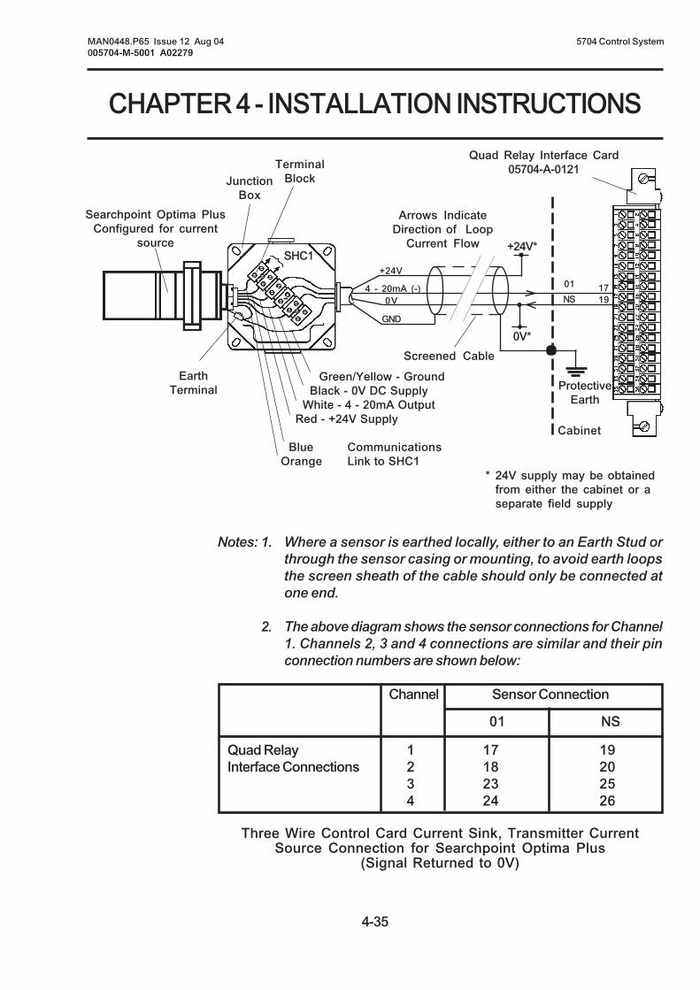
4-35
CHAPTER 4 - INSTALLATION INSTRUCTIONS
MAN0448.P65 Issue 12 Aug 04 5704 Control System005704-M-5001 A02279
Notes: 1. Where a sensor is earthed locally, either to an Earth Stud orthrough the sensor casing or mounting, to avoid earth loopsthe screen sheath of the cable should only be connected atone end.
2. The above diagram shows the sensor connections for Channel1. Channels 2, 3 and 4 connections are similar and their pinconnection numbers are shown below:
Channel Sensor Connection
01 NS
Quad Relay 1 17 19Interface Connections 2 18 20
3 23 254 24 26
Three Wire Control Card Current Sink, Transmitter CurrentSource Connection for Searchpoint Optima Plus
(Signal Returned to 0V)
4 - 20mA (-)-
EarthTerminal
TerminalBlockJunction
Box
Arrows IndicateDirection of Loop
Current Flow
Green/Yellow - Ground Black - 0V DC Supply White - 4 - 20mA Output Red - +24V Supply
Blue CommunicationsOrange Link to SHC1
SHC1
Searchpoint Optima PlusConfigured for current
source
Screened Cable
01
NS
Quad Relay Interface Card05704-A-0121
1719
Cabinet
ProtectiveEarth
+24V*
0V*
* 24V supply may be obtainedfrom either the cabinet or aseparate field supply
+24V
0V
GND

4-36
MAN0448.P65 Issue 12 Aug 04 5704 Control System005704-M-5001 A02279
CHAPTER 4 - INSTALLATION INSTRUCTIONS
Channel Transmitter Connection
01 NS
Quad Relay 1 17 19Interface Connections 2 18 20
3 23 254 24 26
Three Wire Control Card Current Sink, Transmitter Current SourceConnection for Digi Series (Signal Returned to 0V Supply)
Notes: 1. Where a sensor is earthed locally, either to the Earth Stud or through the sensorcasing or mounting, to avoid earth loops the screen sheath of the cable should onlybe connected at one end.
2. The above diagram shows the sensor connections for Channel 1. Channels 2, 3and 4 connections are similar and their pin connection numbers are shown below:
+24
1234
Block Sensor Connections
Wiring Digi-Cat Digi-Chem Digi-AnaCatalytic ECC Analogue
TerminalSignal Colour Signal Colour Signal Colour
1 GND - GND - - -2 NS Blue C Brown 01 Brown*3 C/T White R White 0V/NS Blue*4 S Brown W Blue +24V
* Valid for 811 and 911. For other sensors, see sensor documentation.
Arrows Indicate Direction ofLoop Current Flow
+24V
4 - 20mA(+)
0V
0V
4-20mA(+)
LK2 Fitted(For Current Source)
Sensors: 704 705783 811910 911
Digi Series
See Table forSensor Wiring Screened Cable
01
NS
Quad Relay Interface Card05704-A-0121
1719
Cabinet
ProtectiveEarth
+24V*
0V*
* 24V supply may be obtainedfrom either the cabinet or aseparate field supply
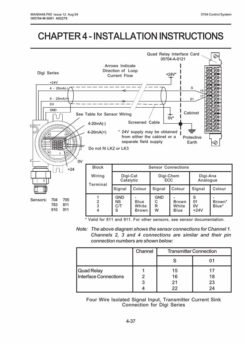
4-37
CHAPTER 4 - INSTALLATION INSTRUCTIONS
MAN0448.P65 Issue 12 Aug 04 5704 Control System005704-M-5001 A02279
Note: The above diagram shows the sensor connections for Channel 1.Channels 2, 3 and 4 connections are similar and their pinconnection numbers are shown below:
Channel Transmitter Connection
S 01
Quad Relay 1 15 17Interface Connections 2 16 18
3 21 234 22 24
Four Wire Isolated Signal Input, Transmitter Current SinkConnection for Digi Series
Block Sensor Connections
Wiring Digi-Cat Digi-Chem Digi-AnaCatalytic ECC Analogue
TerminalSignal Colour Signal Colour Signal Colour
1 GND - GND - S -2 NS Blue C Brown 01 Brown*3 C/T White R White 0V Blue*4 S Brown W Blue +24V
* Valid for 811 and 911. For other sensors, see sensor documentation.
1234
S
01
Screened Cable
Arrows IndicateDirection of Loop
Current Flow
+24V
4 - 20mA(-)
4 - 20mA(+)
0V
GND
Quad Relay Interface Card05704-A-0121
15
17
0V
+24
4-20mA(-)
4-20mA(+)
Do not fit LK2 or LK3
Sensors: 704 705783 811910 911
See Table for Sensor Wiring Cabinet
ProtectiveEarth
+24V*
0V*
Digi Series
* 24V supply may be obtainedfrom either the cabinet or aseparate field supply

4-38
MAN0448.P65 Issue 12 Aug 04 5704 Control System005704-M-5001 A02279
CHAPTER 4 - INSTALLATION INSTRUCTIONS
4 - 20mA (-)
0V
Note: The above diagram shows the sensor connections for Channel 1.Channels 2, 3 and 4 connections are similar and their pinconnection numbers are shown below:
Channel Sensor Connection
S 01
Quad Relay 1 15 17Interface Connections 2 16 18
3 21 234 22 24
Four Wire Floating Signal Input, Transmitter Current SinkConnection
Series 2000 ULSensor
Terminal Block
S
01
ScreenedCable
Quad Relay Interface Card05704-A-0121
15
17
Cabinet
ProtectiveEarth
+24V
0V
Arrows IndicateDirection of Loop
Current Flow
NoLinks
+24V
4 - 20mA (+)
Barrier Safety Ground

4-39
CHAPTER 4 - INSTALLATION INSTRUCTIONS
MAN0448.P65 Issue 12 Aug 04 5704 Control System005704-M-5001 A02279
1
2
Quad Relay InterfaceCard
05704-A-0121
Double ISSafety Barrier
x 3
S
01
Arrows IndicateDirection of Loop
Current Flow
Two Core Screened Cable
GND
IS Series 2000Toxic Sensor
Terminal Block
Earth Stud
15
17
19
12.5 IS Transmitter Connections
If the measuring resistance is in the negative supply line, a doublesafety barrier must be used.
Note: The above diagram shows the sensor connections for Channel 1.The connections for Channels 2, 3 and 4 are similar and their pinconnection numbers are shown below:
Channel Sensor Connection
S 01 0V
Quad Relay 1 15 17 19Interface Connections 2 16 18 20
3 21 23 254 22 24 26
IS Series 2000 Toxic Sensor With Double Safety Barrier
Cabinet
ProtectiveEarth
x 3
NS

4-40
MAN0448.P65 Issue 12 Aug 04 5704 Control System005704-M-5001 A02279
CHAPTER 4 - INSTALLATION INSTRUCTIONS
35 36
33 34
31 32
29 30
27 28
25 26
23 24
21 22
19 20
17 18
15 16
13 14
11 12
9 10
7 8
5 6
3 4
1 2
Quad Relay Interface Card05704-A-0121
Arrows Indicate Direction ofLoop Current Flow
Single ISSafety Barrier
x3
x3
CabinetTwo Core Screened Cable
191715
01
NS
S
ProtectiveEarth
Loop + to Relay Card S
Loop - to Relay Card 01
Screen to Ground
Lifeline
If the measuring resistance is in the negative supply line, a double safetybarrier must be used.
Note 1: *To ensure that the input circuit is properly referred to thesafety barrier it is necessary to connect the isolated 0V to thebarrier ground.
2: The above diagram shows the sensor connections for Channel1. The connections for Channels 2, 3 and 4 are similar andtheir pin connection numbers are shown below:
Channel Sensor Connection
S 01 0V
Quad Relay 1 15 17 19Interface Connections 2 16 18 20
3 21 23 254 22 24 26
IS Lifeline Sensor With Double Safety Barrier

4-41
CHAPTER 4 - INSTALLATION INSTRUCTIONS
MAN0448.P65 Issue 12 Aug 04 5704 Control System005704-M-5001 A02279
13. OUTPUT CONNECTIONS
13.1 Relay Outputs
Note: The FAULT relay is permanently configured for normallyENERGISED operation in the non-fault condition.
CAUTION
When mains ac is connected to the relay contacts:
a. The ac supply should be fused at 5A maximum.
b. A safety earth connection should be made to the groundterminal of the relay card.
There are two relay card types providing different levels of alarm relaycapability (See Chapter 2 Section 5).
The cabling to the relays should where possible be kept away from thesensor cabling, especially those cables carrying mains supplies. Thefollowing figure shows the relay contact connections as shown on theterminal block.
Com
NO
NC
EnergisedContactPosition
Com
NO
NC
De-energisedContactPosition
De-energised and Energised Relays Showing Contact Positions
The alarm relays may be configured for either normally de-energised ornormally energised operation. Check the configuration sheet suppliedwith the system to determine the operating mode of the relays on eachchannel. The energisation mode of the relays can be reconfigured easilyusing a computer attached to the Engineering Port. Contact ZellwegerAnalytics or your local agent for more information.
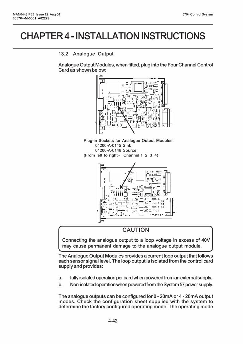
4-42
MAN0448.P65 Issue 12 Aug 04 5704 Control System005704-M-5001 A02279
CHAPTER 4 - INSTALLATION INSTRUCTIONS
13.2 Analogue Output
Analogue Output Modules, when fitted, plug into the Four Channel ControlCard as shown below:
CAUTION
Connecting the analogue output to a loop voltage in excess of 40Vmay cause permanent damage to the analogue output module.
The Analogue Output Modules provides a current loop output that followseach sensor signal level. The loop output is isolated from the control cardsupply and provides:
a. fully isolated operation per card when powered from an external supply.b. Non-isolated operation when powered from the System 57 power supply.
The analogue outputs can be configured for 0 - 20mA or 4 - 20mA outputmodes. Check the configuration sheet supplied with the system todetermine the factory configured operating mode. The operating mode
Plug-in Sockets for Analogue Output Modules:04200-A-0145 Sink04200-A-0146 Source
(From left to right - Channel 1 2 3 4)

4-43
CHAPTER 4 - INSTALLATION INSTRUCTIONS
MAN0448.P65 Issue 12 Aug 04 5704 Control System005704-M-5001 A02279
can be reconfigured easily using a computer attached to the EngineeringPort. Contact Zellweger Analytics or your local agent for more information.
Note: With software versions prior to 1V6, the analogue output signalmay not properly reflect the sensor signal when the sensor signalis outside the normal measuring range.
The analogue outputs can be connected to voltage input device (eg.chart recorders) by including an external sense resistor in series witheach loop and connecting the device input in parallel with the resistor. ie.Use a 100 ohm resistor and select an input range of 2V on the chartrecorder.
The recommended connections are:
Channel Analogue Power Supply
Output 0V 24V
Quad Relay 1 29 28 27Interface Connections 2 30 28 27
3 31 28 274 32 28 27
Isolated Analogue Output Connection with Power Sourced fromProgrammable Logic Controller Using Sink Module
Analogue Channel 1
Analogue OV
0V
+24V
(18V to 40V)
Quad Relay Interface Card 05704-A-0121
Four Channel Control Card Fitted with:
Analogue Output Module (Sink) 04200-A-0145
ProgrammableLogic
Controller
29
2827
Analogue 24V

4-44
MAN0448.P65 Issue 12 Aug 04 5704 Control System005704-M-5001 A02279
CHAPTER 4 - INSTALLATION INSTRUCTIONS
Isolated Analogue Output Connection with Power Sourced fromProgrammable Logic Controller Using Source Module
Analogue 24V
Analogue Channel 1
Analogue OV
0V
+24V
(18V to 40V)
Quad Relay Interface Card 05704-A-0121
Four Channel Control Card Fitted with:
Analogue Output Module (Source) 04200-A-0146
ProgrammableLogic
Controller
27 28
Channel Analogue Power Supply
Output 0V 24V
Quad Relay 1 29 28 27Interface Connections 2 30 28 27
3 31 28 274 32 28 27
29

4-45
CHAPTER 4 - INSTALLATION INSTRUCTIONS
MAN0448.P65 Issue 12 Aug 04 5704 Control System005704-M-5001 A02279
Non-isolated Analogue Output Connection with Power fromSystem 57 Using Source Module
Quad Relay Interface Card 05704-A-0121
Four Channel Control Card Fitted with:
Analogue Output Module (Sink) 04200-A-0145
Non-isolated Analogue Output Connection with Power fromSystem 57 Using Sink Module
CurrentSense
Analogue 24V
Quad Relay Interface Card 05704-A-0121
Four Channel Control Card Fitted with:
Analogue Output Module (Source) 04200-A-0146
27
29
28
Analogue Channel 1
Analogue 0V
+24V
(18V to 40V)
0V
CurrentSense
29
28
Analogue Channel 1
Analogue 0V
+24V
(18V to 40V)
0V
27
Anlogue 24V

4-46
MAN0448.P65 Issue 12 Aug 04 5704 Control System005704-M-5001 A02279
CHAPTER 4 - INSTALLATION INSTRUCTIONS
Analogue Output Connection with 100 Ohm Sense Resistor andParallel Chart Recorder Using Source Module
Quad Relay Interface Card 05704-A-0121
Four Channel Control Card Fitted with:
Analogue Output Module (Sink) 04200-A-0145
Analogue 24V
Quad Relay Interface Card 05704-A-0121
Four Channel Control Card Fitted with:
Analogue Output Module (Source) 04200-A-0146
27
29
28Analogue Channel 1
Analogue 0V
+24V
(18V to 40V)
0V
ChartRecorder
InputR = 100
+
-
Analogue Output Connection with 100 Ohm Sense Resistor andParallel Chart Recorder Using Sink Module
ChartRecorder
InputR = 100
+
- 29
28Analogue Channel 1
Analogue 0V
+24V
(18V to 40V)
0V
27
Anlogue 24V

4-47
CHAPTER 4 - INSTALLATION INSTRUCTIONS
MAN0448.P65 Issue 12 Aug 04 5704 Control System005704-M-5001 A02279
14. REMOTE INPUT CONNECTIONS
CAUTION
Connecting voltages in excess of 32V to the remote inputs maycause permanent damage to the Four Channel Control Card.
There are two remote inputs, RESET and INHIBIT, which are individuallyconfigurable for active high or active low operating modes. Each input iscommon to all four channels of the Four Channel Control Card. Check theconfiguration sheet supplied with the system to determine the factoryconfigured operating modes. The operating mode can be reconfiguredeasily using a computer attached to the Engineering Port. ContactZellweger Analytics or your local agent for more information.
The switching level of the remote input pins (when enabled) isapproximately +2V with respect to the dc system 0V. The inputs requireless than 5mA drive current and irrespective of configuration are internallypulled down to system 0V.
Active high remote inputs may be left unconnected or can be connectedto +24V via a normally open contact. The remote input will operatewhenever the contact closes.
Active low remote inputs may be connected to +24V via a normallyclosed contact. The remote input will operate whenever the contactopens. Do not leave active low inputs unconnected.

4-48
MAN0448.P65 Issue 12 Aug 04 5704 Control System005704-M-5001 A02279
CHAPTER 4 - INSTALLATION INSTRUCTIONS
Active High Remote Input Connected via Normally Open VoltageFree Contact to +24V
Remote Reset
+24V
Remote InhibitINHIBIT
RESET
Normally Closed Contact
Configured for activelow remote inputs
Quad Relay Interface Card05704-A-0121
Four Channel Control Card05704-A-0145 4 - 20mA05704-A-0144 Catalytic
33
Active Low Remote Input Connected via Normally ClosedVoltage Free Contact to +24V
34
+24V
(18V to 32V)
Remote Reset
+24V
Remote Inhibit
Configured for activehigh remote inputs
Quad Relay Interface Card05704-A-0121
Normally Open Contact
INHIBIT
RESET
Four Channel Control Card05704-A-0145 4 - 20mA05704-A-0144 Catalytic
33
+24V
(18V to 32V)
34

4-49
CHAPTER 4 - INSTALLATION INSTRUCTIONS
MAN0448.P65 Issue 12 Aug 04 5704 Control System005704-M-5001 A02279
15. DC POWER CONNECTIONS
15.1 General
CAUTION
The ratings of power supplies should be checked by calculating asystem power budget as outlined in Section 5.
IMPORTANT
The System 57 must be earthed
DC power is connected to the System 57 via the DC Input Card terminalblock TB1 and via the Quad Relay Interface Cards.
The DC Input Card provides diode isolation to permit the connection oftwo separate power supplies. eg. A mains derived dc power supply andbattery backup dc supply. Note that current will be drawn from the supplyinput with the highest voltage and in some circumstances current will beshared between the two inputs. Each of the two inputs have twin +24Vand 0V terminals for easy through power connection or paralleling ofinput sources.
A fused +24V output, which is the combination of both dc inputs, isprovided for powering ancillary devices.
Site DC Supply and Auxiliary Battery Backup DC Power SupplyConnections, With Through Wiring
System Earth
Aux Battery24V DC Supply
Aux BatteryThrough Wiring
Site PSUThrough Wiring
Site PSU24V DC Nominal
24V Output toAncillary Equipment
FS110A
12
11
10
9
8
7
6
5
4
3
2
1
TB1

4-50
MAN0448.P65 Issue 12 Aug 04 5704 Control System005704-M-5001 A02279
CHAPTER 4 - INSTALLATION INSTRUCTIONS
15.2 Individually Powered Control Cards
Notes: 1. In individually powered control systems a DC connection isstill required to the DC Input Card in order to provide power tothe Engineering Card.
2. The supply to each control card must be externally fuse ratedat 2A maximum.
Individually powered control cards may be required for two reasons:
a. Where the local or other regulations dictate individual connections inorder to achieve the highest integrity for power distribution.
b. In densely populated racks to reduce the current load on thebackplane.
The System 57 DC Input Card supply is fused at 10A and to ensurereliable operation of the system, the maximum continuous current flow inthe rack backplane should be less than 8A. In 16 channel racks,substantially populated with four channel catalytic control cards, thisbackplane current can be exceeded, especially where long sensor cableruns are present. Therefore, as a general rule, where more than eightcatalytic control cards are used in a single rack, these should be poweredusing the individually powered scheme.
Individual powering of a four channel control card is easily achieved asfollows:
(1) On the Four Channel Control Card, remove the link LK1 from position1 - 2 and refit in position 2 - 3 as shown below:
(2) Wire the +24V DC power supply to the respective Quad Relay InterfaceCard terminals 35 (+24V) and 36 (0V) as shown above:
Four Channel ControlCard Catalytic Input
Four Channel ControlCard 4 - 20mA Input
LK1
35 36
+24V
(18V to 32V)
0V
1 2 3
ExternalFuse 2A
Maximum

4-51
CHAPTER 4 - INSTALLATION INSTRUCTIONS
MAN0448.P65 Issue 12 Aug 04 5704 Control System005704-M-5001 A02279
16. AC TO DC POWER SUPPLY UNIT CONNECTIONS
WARNING
The AC to DC Power Supply Unit must be earthed.
The input supply to the AC to DC Power Supply Unit may be:
a. an ac supply of 85V to 264V at 47Hz to 440Hz.
b. a dc supply of 110V to 340V (Refer to Zellweger Analytics forinformation on dc supplies).
The supply must be fused at 6A maximum at the supply source. eg. At thedistribution panel. Where additional cabling is used this must be mainsrated for a minimum of 6A.
Two cables emerge from the rear of the AC to DC Power Supply Unit:
a. AC Input
The ac supply cable connections are colour coded BROWN - LIVE,BLUE - NEUTRAL and YELLOW/GREEN - EARTH. If necessary,these wires should be connected to the ac supply via a suitableintermediate mains rated terminal block.
b. DC Output
The dc output cable connections are colour coded RED - +24V andBLACK - 0V. These should be connected to the appropriate DC InputCard terminals.
It is recommended that the AC to DC Power Supply Unit is connected tothe system earth using the earth stud provided at the rear of the unit. Foradditional electrical safety a Residual Current Device (RCD) type circuitbreaker should be used at the supply source.

4-52
MAN0448.P65 Issue 12 Aug 04 5704 Control System005704-M-5001 A02279
CHAPTER 4 - INSTALLATION INSTRUCTIONS
Twin Sub-Unit AC to DC Power Supply Connections to AC Supply, Earth and DCInput Card, Together with Auxiliary Battery Backup Supply
Brown
Blue
Green/Yellow
AC to DC PSU50W Sub-Unit
EarthStud
AC to DC PSU50W Sub-Unit
SystemEarth
DC Input CardTB1
Auxiliary 24V DC Supply(eg. Battery Backup)
24V Output to AncillaryEquipment
SystemEarth
AC InputSupply
Brown
Blue
Green/Yellow
IntermediateTerminal
Block
L
N
E
L
N
E
12
11
10
9
8
7
6
5
4
3
2
1
EarthStud
Red
Black
Red
Black
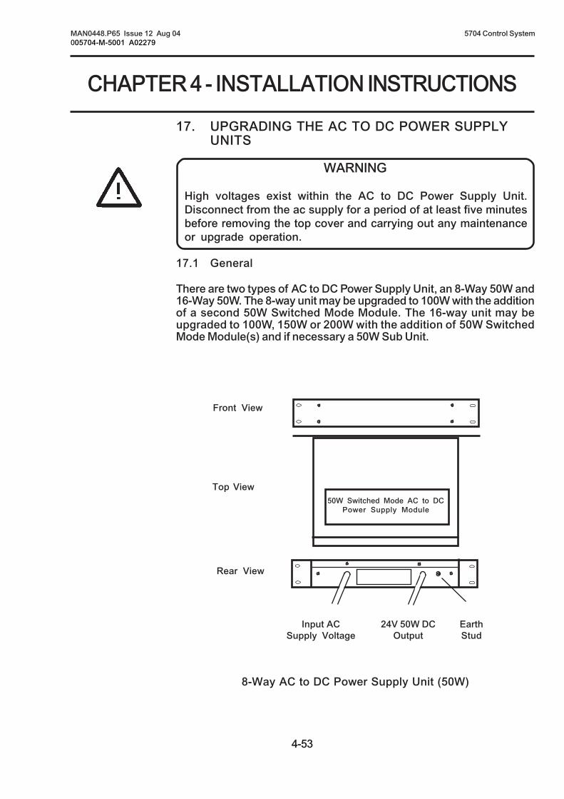
4-53
CHAPTER 4 - INSTALLATION INSTRUCTIONS
MAN0448.P65 Issue 12 Aug 04 5704 Control System005704-M-5001 A02279
17. UPGRADING THE AC TO DC POWER SUPPLYUNITS
WARNING
High voltages exist within the AC to DC Power Supply Unit.Disconnect from the ac supply for a period of at least five minutesbefore removing the top cover and carrying out any maintenanceor upgrade operation.
17.1 General
There are two types of AC to DC Power Supply Unit, an 8-Way 50W and16-Way 50W. The 8-way unit may be upgraded to 100W with the additionof a second 50W Switched Mode Module. The 16-way unit may beupgraded to 100W, 150W or 200W with the addition of 50W SwitchedMode Module(s) and if necessary a 50W Sub Unit.
8-Way AC to DC Power Supply Unit (50W)
Front View
Top View
Rear View
50W Switched Mode AC to DCPower Supply Module
EarthStud
24V 50W DCOutput
Input ACSupply Voltage
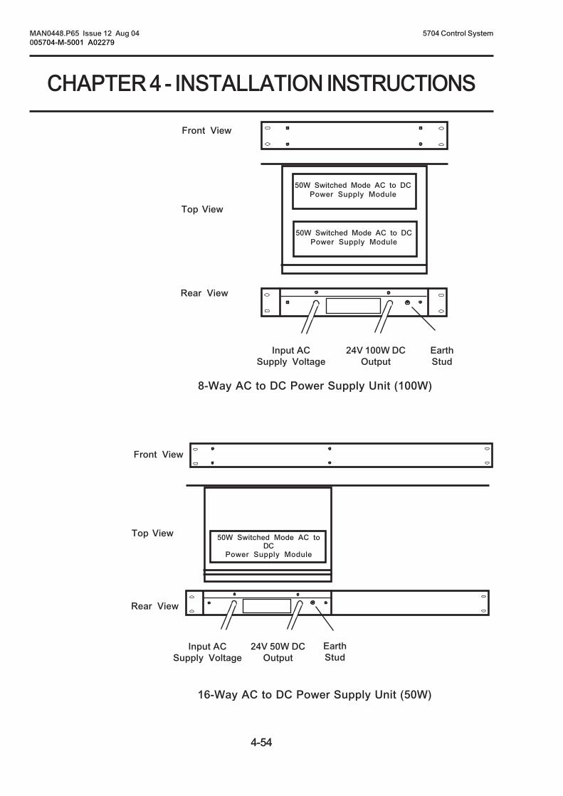
4-54
MAN0448.P65 Issue 12 Aug 04 5704 Control System005704-M-5001 A02279
CHAPTER 4 - INSTALLATION INSTRUCTIONS
8-Way AC to DC Power Supply Unit (100W)
16-Way AC to DC Power Supply Unit (50W)
Front View
Top View
Rear View
50W Switched Mode AC to DCPower Supply Module
50W Switched Mode AC to DCPower Supply Module
EarthStud
24V 100W DCOutput
Input ACSupply Voltage
Front View
Top View
Rear View
50W Switched Mode AC toDC
Power Supply Module
EarthStud
24V 50W DCOutput
Input ACSupply Voltage

4-55
CHAPTER 4 - INSTALLATION INSTRUCTIONS
MAN0448.P65 Issue 12 Aug 04 5704 Control System005704-M-5001 A02279
16-Way AC to DC Power Supply Unit (100W)
16-Way AC to DC Power Supply Unit (150W)
Front View
Top View
Rear View
50W Switched Mode AC toDC
Power Supply Module
50W Switched Mode AC toDC
Power Supply Module
50W Switched Mode AC toDC
Power Supply Module
EarthStud
24V 50W DCOutput
Input ACSupply VoltageEarth
Stud
24V 100W DCOutput
Input ACSupply Voltage
Front View
Top View
Rear View
50W Switched Mode AC toDC
Power Supply Module
50W Switched Mode AC toDC
Power Supply Module
Input ACSupply Voltage
24V 100W DCOutput
EarthStud

4-56
MAN0448.P65 Issue 12 Aug 04 5704 Control System005704-M-5001 A02279
CHAPTER 4 - INSTALLATION INSTRUCTIONS
16-Way AC to DC Power Supply Unit (200W)
17.2 8-Way and 16-Way AC to DC Power Supply Unit Upgradeto 100W
To upgrade the 8-Way or 16-Way AC to DC Power Supply Units to 100Wproceed as follows:
(1) Remove and retain the screws securing the top cover of the powersupply unit and lift the cover clear.
(2) Cut and remove the retaining straps that secure the unused ac and dcconnecting cables to the sub-unit chassis.
(3) On the 50W Switched Mode Module to be added to the 50W Sub-Unit, remove and discard the four packing screws from the undersideof the module, however, retain the long nuts and washers.
(4) On the 50W Switched Mode Module to be added to the 50W Sub-Unit, ensure that the spacers under the printed circuit board arecorrectly located.
50W Switched Mode AC toDC
Power Supply Module
50W Switched Mode AC toDC
Power Supply Module
Front View
Top View
Rear View
50W Switched Mode AC toDC
Power Supply Module
50W Switched Mode AC toDC
Power Supply Module
EarthStud
24V 100WDC Output
Input ACSupply Voltage
EarthStud
24V 100WDC Output
Input ACSupply Voltage

4-57
CHAPTER 4 - INSTALLATION INSTRUCTIONS
MAN0448.P65 Issue 12 Aug 04 5704 Control System005704-M-5001 A02279
(5) Insert the module, with the same orientation as the already fittedmodule, into the vacant position inside the 50W Sub Unit and secureusing the washers and long nuts retained in Step (3).
(6) Connect the 50W Sub Unit second ac input and 24V dc output cableconnectors to the ac input terminal CN1 and dc output terminal CN2respectively on the added 50W Switched Mode Module as shownbelow:
(7) Refit the top cover.
17.3 16-Way AC to DC Power Supply Unit Upgrade to 150W or200W
To upgrade the 16-Way AC to DC Power Supply Unit to 150W or 200Wproceed as follows:
(1) Fit a second 50W Sub unit, containing a 50W Switched Mode Module,to the 16-way AC to DC Power Supply Unit front panel using thefixings supplied.
(2) When an upgrade to 200W is required, fit a further 50W SwitchedMode Module into the new 50W Sub unit as indicated in Section17.2.
CN2DC Output
CN1AC Input

4-58
MAN0448.P65 Issue 12 Aug 04 5704 Control System005704-M-5001 A02279
CHAPTER 4 - INSTALLATION INSTRUCTIONSUSER NOTES

5-1
MAN0448.P65 Issue 12 Aug 04 5704 Control System005704-M-5001 A02279
CHAPTER 5 - COMMISSIONING ANDMAINTENANCE INSTRUCTIONS
5704 SERIES
CONTROL SYSTEM
CHAPTER 5
COMMISSIONING AND MAINTENANCE
INSTRUCTIONS

5-2
MAN0448.P65 Issue 12 Aug 04 5704 Control System005704-M-5001 A02279
CHAPTER 5 - COMMISSIONING ANDMAINTENANCE INSTRUCTIONS
CONTENTSSection Page
1. General 5-3
2. Start Up Procedure 5-3
3. Calibration 5-5
4. Maintenance 5-6
5. Error Codes 5-7
5.1 General 5-75.2 Start-up Hardware Faults 5-85.3 Run Time Errors 5-105.4 Calibration Errors 5-135.5 System Errors 5-165.6 Miscellaneous Errors 5-17
6. FAULT FINDING 5-18

5-3
MAN0448.P65 Issue 12 Aug 04 5704 Control System005704-M-5001 A02279
CHAPTER 5 - COMMISSIONING ANDMAINTENANCE INSTRUCTIONS
WARNING
High ac mains voltages may be present at the system power supplyunit and at the relay terminals of the interface cards. Appropriatesafety precautions must be taken when commissioning or servicingthe system.
IMPORTANT
Commissioning and maintenance of the system should be carried outby trained authorised personnel only.
1. GENERAL
The following guide to commissioning and maintenance should beused in conjunction with the relevant instructions issued with thesensors being used.
2. START UP PROCEDURE
A detailed check of the system wiring should be carried out prior to thisstart-up procedure.
Start-up the system as follows:
(1) Ensure that the system power supply is switched off.
(2) Disconnect the power supply connections to the DC Input Card byremoving the two part connector TB1 and TB2 if fitted.
(3) Unscrew the two retaining screws used to secure the control cardsand then, using the extraction tool, partially remove the cards fromthe rack so that there is no electrical connection between thecontrol cards and the backplane.
(4) Switch on the system power supply.
(5) Check that a voltage of between 18V and 32V dc exists at theterminal block TB1 (and for individually power systems on each ofthe Quad Relay Interface Card terminals 35 and 36).
(6) Switch off the power supply.

5-4
MAN0448.P65 Issue 12 Aug 04 5704 Control System005704-M-5001 A02279
CHAPTER 5 - COMMISSIONING ANDMAINTENANCE INSTRUCTIONS
(7) Reconnect the terminal block TB1 to the DC Input Card.
(8) Switch on the system power supply.
(9) Check that a voltage of between 18V and 32V dc still exists at theterminal block TB1.
(10) Check that the Engineering Card front panel power on ( ) greenLED is illuminated and the unlocked ( ) LED is flashing.
(11) Push the control card in slot 1 fully into the rack so that it makesconnection with the backplane and secure with the two securingscrews.
(12) Check that the display operates and that the INHIBIT LED on thecontrol card front panel is illuminated.
(13) Check that after the pre-defined start up inhibit period, typically 30seconds, the INHIBIT LED are extinguished.
(14) Check the operation of each connected sensor by checking theBEAD mA and mV SIGNAL for a catalytic sensor or the mASIGNAL for a 4 - 20mA sensor.
(15) Repeat Steps (11) to (14) for the remaining control cards in therack.
(16) Reconnect the terminal block TB2 to the DC Input Card and test theoptional Engineering Card module in accordance with the relevantoperating manual instructions.
(17) Verify the alarm configuration for each channel using the relay testprocedure outlined in Chapter 7 Section 6.
(18) Verify that the System 57 Control Cards and power supply areoperating within the maximum specified operating temperature of55oC.

5-5
MAN0448.P65 Issue 12 Aug 04 5704 Control System005704-M-5001 A02279
CHAPTER 5 - COMMISSIONING ANDMAINTENANCE INSTRUCTIONS
3. CALIBRATION
Leave the connected sensors to stabilise for a period as specified inthe sensor manual.
Adjust the sensor head current of catalytic sensors as described inChapter 7 Section 7 to the required value as indicated in the sensoroperating instructions.
Using the procedures specified for the type of sensors being used,follow the zero and 1st span operational guide in Chapter 7 Sections 8and 10, and calibrate each channel.

5-6
MAN0448.P65 Issue 12 Aug 04 5704 Control System005704-M-5001 A02279
CHAPTER 5 - COMMISSIONING ANDMAINTENANCE INSTRUCTIONS
4. MAINTENANCE
To ensure that the system functions correctly, maintenance should becarried out on a regular basis as dictated by the site regulations andinstructions for the type of sensor being used. For installations in theEU, EN 50073 should be followed.”
The system should be maintained in a clean condition and kept freefrom dust and grease. The following checks should be made annually,or more frequently if required by local regulations or procedures:
(1) Check and if necessary tighten all terminations to the DC InputCard, Quad Relay Interface Cards and if fitted to the ExpansionRelay Card.
(2) Check that the Engineering Card power on ( ) green LED isilluminated and all other LEDs are extinguished.
(3) Check the display of each channel in use, of every control card,indicates a normal reading with no error messages.
(4) Select each channel of every control card, in turn, and check thatchannels sensor signal reading and, if a catalytic sensor isconnected, the sensor bridge current.
(5) With the Engineering Key fitted to the Engineering Card, select eachchannel of every control card in turn and enter the alarms test function.
(6) Check the alarm levels, alarm LED operation alarm relay operationand display operation for each channel.
(7) Check the operation of all fault and inhibit relays.
(8) Check that, with the sensor in a gas free atmosphere, the displayindicates zero. If appropriate adjust the zero reading using theZERO function.
Note: For oxygen applications the zero function should only be operatedin an oxygen free atmosphere. Under normal atmosphereconditions the display should indicate 21% ± 0.5% v/v, this can beadjusted by using the SPAN function.
The System 57 control cards and engineering cards carry out continualself checking of the integrity of the hardware, software and sensoroperation. In the event of a problem, and depending on the type ofproblem, the control card will indicate either an error message on theLCD display or will operate the fault LED and relay output.

5-7
MAN0448.P65 Issue 12 Aug 04 5704 Control System005704-M-5001 A02279
CHAPTER 5 - COMMISSIONING ANDMAINTENANCE INSTRUCTIONS
5. ERROR CODES
5.1 General
Operating errors within the system are indicated on the LCD messagedisplay as an error code. The error codes used and their meaning arelisted in the following sections. These sections also contain appropriateinformation pertaining to the likely cause of the error message beingdisplayed and an indication on how the error affects the operation of thechannel card.
Error Code: This relates to the error code message ERxx displayed onthe LCD message display. If more than one error ispresent simultaneously, the error with the highest codenumber is displayed
Card Status: This refers to the condition of the control card operation.
Active means that the card is still processing signalsfrom the connected sensor and, in the event of the sensordetecting gas, will still activate any configured alarmoutputs.
Non active means that it is not possible for the controlcard to generate any alarms in response to the sensordetecting gas.
Fault Signal: This refers to the indication of the fault condition inresponse to the error condition.
Yes means that the appropriate channel front panel faultLED and any configured fault relay will be operated.
No means that no fault indication is given. The errorcondition that causes these general warning messagesis of a minor nature and the channel card will continue tooperate. The condition should however still beinvestigated.
Latch: This refers to the condition of the error message and theassociated fault signal.
Yes means that the control card will continue to displaythe error message until the condition causing the errorhas cleared and the reset push-button has been operated.
No means that the error message will clear automaticallyonce the condition causing the error message hascleared.
Conf. means that the latch/non-latch condition isconfigurable using the Engineering Interface Software.

5-8
MAN0448.P65 Issue 12 Aug 04 5704 Control System005704-M-5001 A02279
CHAPTER 5 - COMMISSIONING ANDMAINTENANCE INSTRUCTIONS
All Non Yes YesActive
All Non Yes YesActive
All Non Yes YesActive
98 ROM Failure.
The ROM stores the channel card program.
The ROM failure message is displayed ifthere are errors in the read byte test duringthe system start-up or periodic self test.
This is a serious card failure and, as such,the card needs to be replaced.
97 EEPROM Failure.
The EEPROM holds the applicationconfiguration data.
The EEPROM failure message is displayed ifthere is a checksum difference or it has beenimpossible to carry out a checksum test duringstart-up or periodic self test.
This is a serious card failure and, as such,the card needs to be replaced.
5.2 Self Test Faults
Note: In addition to some of the following fault codes that may bedisplayed, the control card ATTN LED will flash one second onone second off should a hardware or software fault be detected onthe control card.
99 RAM Failure.
RAM stores the working values duringoperation.
The RAM failure message is displayed if thereare errors in the read/write byte test duringthe system start-up or periodicself test.
This is a serious card failure and, as such,the card needs to be replaced.
Error Error Code Meaning Software Card Fault LatchCode Version Status Signal

5-9
MAN0448.P65 Issue 12 Aug 04 5704 Control System005704-M-5001 A02279
CHAPTER 5 - COMMISSIONING ANDMAINTENANCE INSTRUCTIONS
96 No Vps.
Vps is a voltage which is used to set theabsolute value reference for the reading scalingfactor.
The no Vps message is only displayed on achannel card that has not been factory tested.
This is a serious card failure and, as such, thecard needs to be replaced.
95 Not used.
94 Not used.
93 Configuration Fault
The configuration fault message is displayedduring start-up if the channel card has noconfiguration information or the configurationis not valid..
This is a serious card failure and, as such, thecard needs to be replaced.
92 Not used.
91 Power Fail Error
The power fail error message is displayed if thesystem supply voltage falls below approximately16V dc.
The error latches* if the power failure delay isnot enabled.
Check the operation of the power supply. Whenthe power is restored, check the operation ofthe system.
All Non Yes YesActive
All Non Yes YesActive
1V5 Non Yes NoActive
1V6 Non Yes Conf*or Active
later
Error Error Code Meaning Software Card Fault LatchCode Version Status Signal
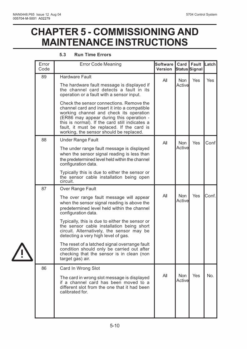
5-10
MAN0448.P65 Issue 12 Aug 04 5704 Control System005704-M-5001 A02279
CHAPTER 5 - COMMISSIONING ANDMAINTENANCE INSTRUCTIONS
5.3 Run Time Errors
89 Hardware Fault
The hardware fault message is displayed ifthe channel card detects a fault in itsoperation or a fault with a sensor input.
Check the sensor connections. Remove thechannel card and insert it into a compatibleworking channel and check its operation(ER86 may appear during this operation -this is normal). If the card still indicates afault, it must be replaced. If the card isworking, the sensor should be replaced.
88 Under Range Fault
The under range fault message is displayedwhen the sensor signal reading is less thanthe predetermined level held within the channelconfiguration data.
Typically this is due to either the sensor orthe sensor cable installation being opencircuit.
87 Over Range Fault
The over range fault message will appearwhen the sensor signal reading is above thepredetermined level held within the channelconfiguration data.
Typically, this is due to either the sensor orthe sensor cable installation being shortcircuit. Alternatively, the sensor may bedetecting a very high level of gas.
The reset of a latched signal overrange faultcondition should only be carried out afterchecking that the sensor is in clean (nontarget gas) air.
86 Card In Wrong Slot
The card in wrong slot message is displayedif a channel card has been moved to adifferent slot from the one that it had beencalibrated for.
All Non Yes YesActive
All Non Yes ConfActive
All Non Yes Conf.Active
All Non Yes No.Active
Error Error Code Meaning Software Card Fault LatchCode Version Status Signal

5-11
MAN0448.P65 Issue 12 Aug 04 5704 Control System005704-M-5001 A02279
CHAPTER 5 - COMMISSIONING ANDMAINTENANCE INSTRUCTIONS
This allows cards to be moved to alternativeslot locations for fault finding purposes. Thismessage may also be displayed when fittinga new channel card or fitting a sparereplacement. The message can be clearedby calibrating the channel card to the newslot location and connected sensor.
Depending on the alarm configuration,moving channel cards to alternative slotsmay compromise the generation of alarms.The alarm operation should be checked afterthe card has been moved and calibrated.
85 Not used
84 Datasum Changed
The datasum changed message is displayedif there is a failure in the channel card RAMduring normal operation.
The card should be reset by removing thepower to the card. This is achieved byremoving the card from the rack slot andthen replacing the card back into the rackslot. If the error message persists the cardneeds replacing.
83 Bead Current Fault
The current setting fault message isdisplayed when the control card is unable toset or maintain the correct operating currentfor a catalytic sensor.
Check the cable sensor connection andcable line lengths to ensure that themaximum line impedance has not beenexceeded.
82 Lifetime Expired
The lifetime expired message is displayedif the catalytic sensor sensitivity falls tobelow 50% of its original value.
Error Error Code Meaning Software Card Fault LatchCode Version Status Signal
All Non Yes NoActive
1V6 Non Yes Yesor Active
later
All Active No No

5-12
MAN0448.P65 Issue 12 Aug 04 5704 Control System005704-M-5001 A02279
CHAPTER 5 - COMMISSIONING ANDMAINTENANCE INSTRUCTIONS
The lifetime is calculated on the differencebetween the sensitivity measured during 1stSPAN and that measured during subsequentnormal SPANs, and is only updated duringthe SPAN function.
This is a warning that the sensor output isbecoming unacceptably low and may be dueto age or due to the sensor being 'poisoned'by the presence of silicones, sulphur andlead compounds.
The sensor should be replaced.
81 Signal Under Range
The signal under range message isdisplayed when the sensor signal reading isless than a predetermined level held withinthe channel configuration data. Thispredetermined level is below the normaloperating range.
This is typically due to the sensor signaldrifting below the normal zero operating point.This could, depending on the sensor type,be due to large changes in climaticconditions, loose terminal connections, thesensor being poisoned or an early indicationof the failure of the sensor.
In some instances this error can be causedby short circuits in the sensor or cabling.
The channel card should be calibrated andits operation checked
80 Signal Over Range
The signal over range warning message isdisplayed when the sensor signal reading ismore than a predetermined level held withinthe channel configuration data.Thispredetermined level is above the operatingrange.
Error Error Code Meaning Software Card Fault LatchCode Version Status Signal
All Non Yes ConfActive
All Active No Conf

5-13
MAN0448.P65 Issue 12 Aug 04 5704 Control System005704-M-5001 A02279
CHAPTER 5 - COMMISSIONING ANDMAINTENANCE INSTRUCTIONS
This provides a warning that the sensoris detecting a level of gas exceeding theset operating range of the channel.
IMPORTANT
If configured for latching, the display andanalogue output may not indicate thetrue gas concentration when themeasuring range is exceeded.
The reset of a latched signal overrangewarning condition should only be carriedout after checking that the sensor is inclean (non target gas) air.
Error Error Code Meaning Software Card Fault LatchCode Version Status Signal
79 Uncalibrated
The uncalibrated message is displayedfor new channel cards that have neverbeen calibrated.
The channel card should be calibratedand its operation checked.
78 Calibration Overdue
The calibration overdue message isdisplayed when the pre-configuredcalibration interval has expired.
This is a warning message that the sensoris due for calibration. Once the calibrationhas been completed the message willclear.
If required, this function can be disabledusing the Engineering Interface Softwareconfiguration program.
5.4 Calibration Errors
Error Error Code Meaning Software Card Fault LatchCode Version Status Signal
All Non No NoActive
All Active No No
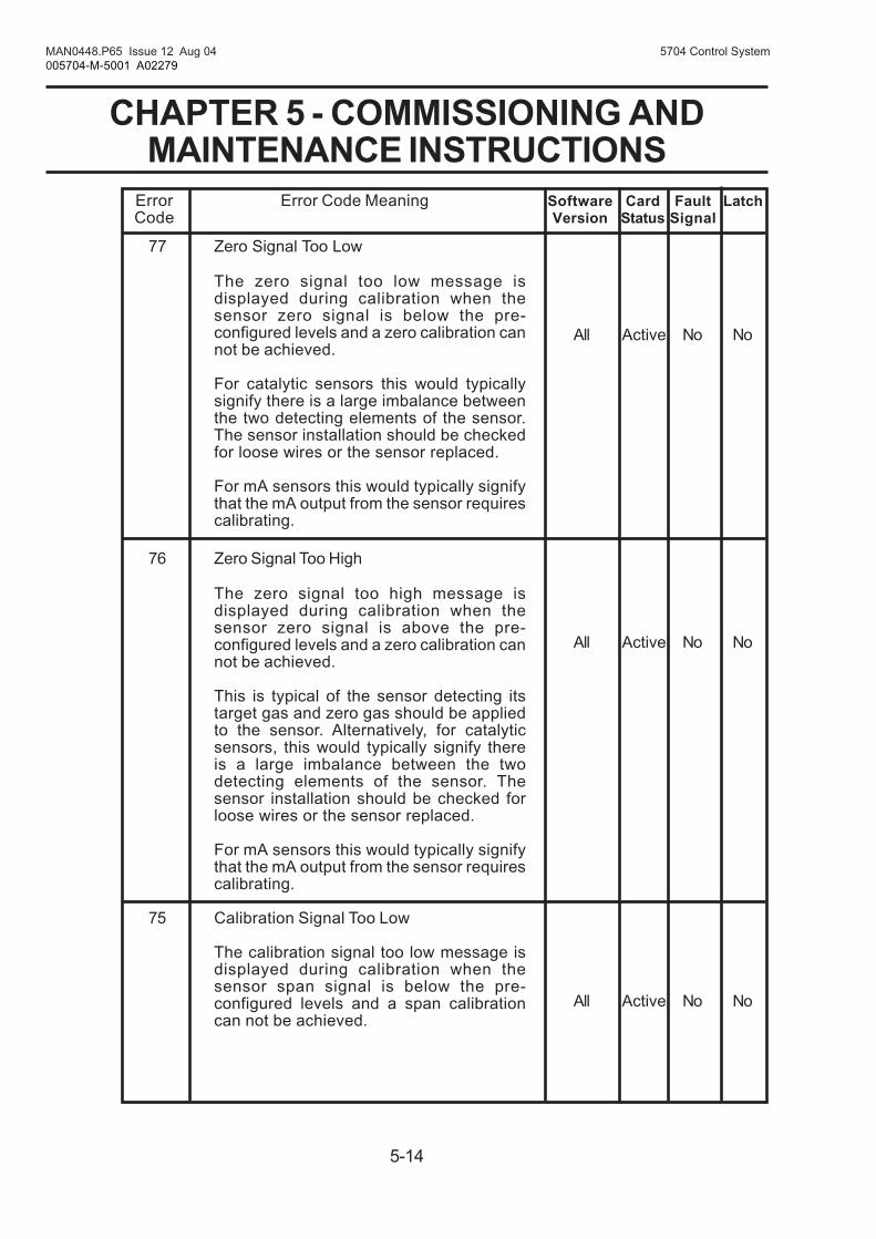
5-14
MAN0448.P65 Issue 12 Aug 04 5704 Control System005704-M-5001 A02279
CHAPTER 5 - COMMISSIONING ANDMAINTENANCE INSTRUCTIONS
77 Zero Signal Too Low
The zero signal too low message isdisplayed during calibration when thesensor zero signal is below the pre-configured levels and a zero calibration cannot be achieved.
For catalytic sensors this would typicallysignify there is a large imbalance betweenthe two detecting elements of the sensor.The sensor installation should be checkedfor loose wires or the sensor replaced.
For mA sensors this would typically signifythat the mA output from the sensor requirescalibrating.
76 Zero Signal Too High
The zero signal too high message isdisplayed during calibration when thesensor zero signal is above the pre-configured levels and a zero calibration cannot be achieved.
This is typical of the sensor detecting itstarget gas and zero gas should be appliedto the sensor. Alternatively, for catalyticsensors, this would typically signify thereis a large imbalance between the twodetecting elements of the sensor. Thesensor installation should be checked forloose wires or the sensor replaced.
For mA sensors this would typically signifythat the mA output from the sensor requirescalibrating.
75 Calibration Signal Too Low
The calibration signal too low message isdisplayed during calibration when thesensor span signal is below the pre-configured levels and a span calibrationcan not be achieved.
Error Error Code Meaning Software Card Fault LatchCode Version Status Signal
All Active No No
All Active No No
All Active No No
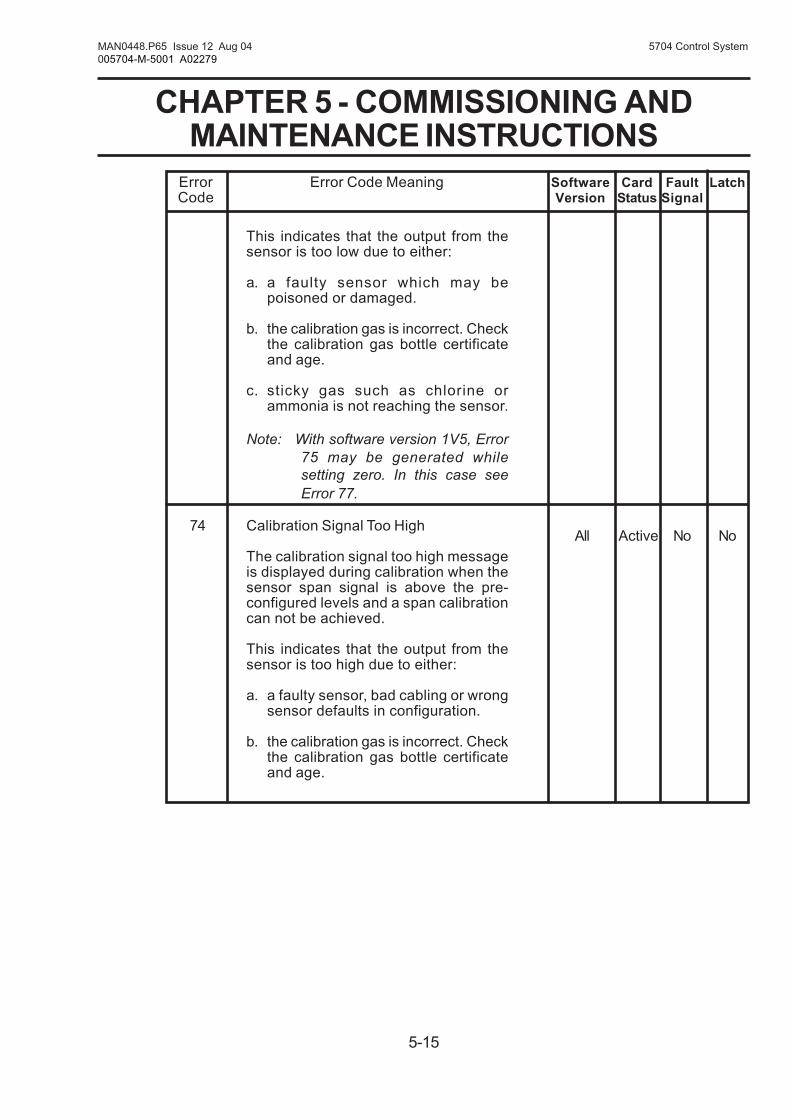
5-15
MAN0448.P65 Issue 12 Aug 04 5704 Control System005704-M-5001 A02279
CHAPTER 5 - COMMISSIONING ANDMAINTENANCE INSTRUCTIONS
This indicates that the output from thesensor is too low due to either:
a. a faulty sensor which may bepoisoned or damaged.
b. the calibration gas is incorrect. Checkthe calibration gas bottle certificateand age.
c. sticky gas such as chlorine orammonia is not reaching the sensor.
Note: With software version 1V5, Error75 may be generated whilesetting zero. In this case seeError 77.
74 Calibration Signal Too High
The calibration signal too high messageis displayed during calibration when thesensor span signal is above the pre-configured levels and a span calibrationcan not be achieved.
This indicates that the output from thesensor is too high due to either:
a. a faulty sensor, bad cabling or wrongsensor defaults in configuration.
b. the calibration gas is incorrect. Checkthe calibration gas bottle certificateand age.
Error Error Code Meaning Software Card Fault LatchCode Version Status Signal
All Active No No

5-16
MAN0448.P65 Issue 12 Aug 04 5704 Control System005704-M-5001 A02279
CHAPTER 5 - COMMISSIONING ANDMAINTENANCE INSTRUCTIONS
5.5 System Errors
69 Invalid Sub-Channel
Indicates a request has been received foran invalid sub-channel address.
68 Printer Not Ready
Indicates that the serial device attached tothe engineering port is not able to acceptdata.
67 Invalid Request
Indicates that an invalid request numberhas been received.
66 Serial Communications Timeout
Serial communications has timed out.
Reset card by removing power to the card.If problem persists, replace the card.
65 Failed Error
Failed to receive command or cardselected.
Reset card by removing power to the card.If problem persists, replace the card.
64 Timeout Error
Backplane command timed out.
Reset card by removing power to the card.If problem persists, replace the card.
63 Slot Inactive Error
Backplane command sent to empty slot.
Reset card by removing power to the card.If problem persists, replace the card.
Error Error Code Meaning Software Card Fault LatchCode Version Status Signal
All Active No No
All Active No No
All Active No No
All Active No No
All Active No No
All Active No No
All Active No No

5-17
MAN0448.P65 Issue 12 Aug 04 5704 Control System005704-M-5001 A02279
CHAPTER 5 - COMMISSIONING ANDMAINTENANCE INSTRUCTIONS
62 Communications Error
A participant in a complex alarm functionhosted by this card has stoppedcommunicating.
Check all cards within the participantgroup are fully inserted into the rack andare functioning correctly.
Error Error Code Meaning Software Card Fault LatchCode Version Status Signal
All Active Yes No
5.6 Miscellaneous Errors
07 Divide By Zero
Internal calculation error.
Reset card by removing power to thecard. If problem persists, replace thecard.
01 Invalid Command
A serial command has been receivedthat is not valid for this card.
Error Error Code Meaning Software Card Fault LatchCode Version Status Signal
All Active No No
All Active No No

5-18
MAN0448.P65 Issue 12 Aug 04 5704 Control System005704-M-5001 A02279
CHAPTER 5 - COMMISSIONING ANDMAINTENANCE INSTRUCTIONS
Action
Disconnect TB1 and measure thevoltage between the +24V dc and0V terminals.
If the voltage is correct, remove theDC Input Card and check the fuseFS1.
If the voltage is not correct, checkthe system power supply unit.
The dc input voltage is too low.
Check dc voltage at the DC InputCard terminals.
There is a hardware fault.
Switch power of and then on again.If problem persists, check thediagnostic printout for error codes
Check that the ac mains voltage isbetween 85V and 264V at the powersupply ac connection wires.
If yes, replace the 50W PowerSupply Module.
Check that power is being appliedto the control card from thebackplane or Quad Interface Cardas applicable and the display stilldoes not read, replace the controlcard.
6. FAULT FINDING
The following table provides a guide to diagnosing various conditionswithin the operation of System 57.
Note: In addition to some of the following fault codes that may bedisplayed, the control card ATTN LED will flash one second on/one second off should a hardware or software fault be detectedon the control card.
Fault
The Engineering Card frontpanel power on ( ) greenLED extinguished.
The Engineering Card frontpanel power on ( ) greenLED flashes at approximatelytwo second intervals.
The Engineering Card frontpanel power on ( ) greenLED flashes at approximately0.5 second intervals.
No dc voltage output fromPower Supply Unit.
No readings on a control carddisplay.
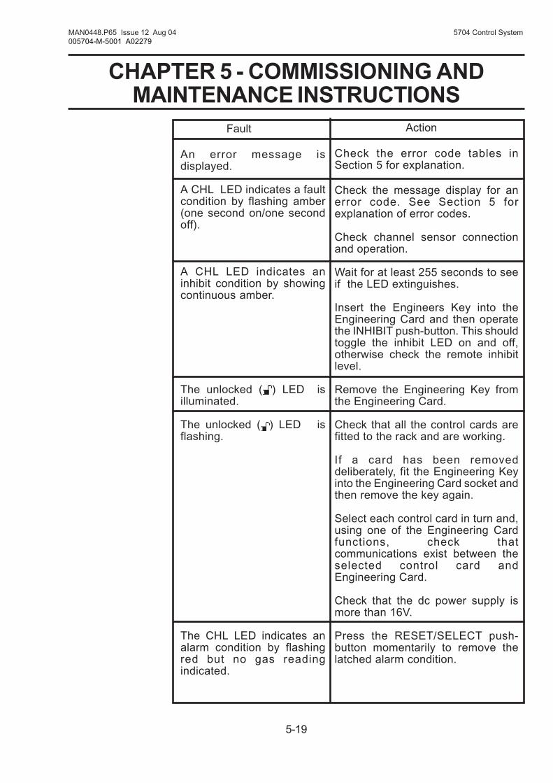
5-19
MAN0448.P65 Issue 12 Aug 04 5704 Control System005704-M-5001 A02279
CHAPTER 5 - COMMISSIONING ANDMAINTENANCE INSTRUCTIONS
Fault
An error message isdisplayed.
A CHL LED indicates a faultcondition by flashing amber(one second on/one secondoff).
A CHL LED indicates aninhibit condition by showingcontinuous amber.
The unlocked ( ) LED isilluminated.
The unlocked ( ) LED isflashing.
The CHL LED indicates analarm condition by flashingred but no gas readingindicated.
Action
Check the error code tables inSection 5 for explanation.
Check the message display for anerror code. See Section 5 forexplanation of error codes.
Check channel sensor connectionand operation.
Wait for at least 255 seconds to seeif the LED extinguishes.
Insert the Engineers Key into theEngineering Card and then operatethe INHIBIT push-button. This shouldtoggle the inhibit LED on and off,otherwise check the remote inhibitlevel.
Remove the Engineering Key fromthe Engineering Card.
Check that all the control cards arefitted to the rack and are working.
If a card has been removeddeliberately, fit the Engineering Keyinto the Engineering Card socket andthen remove the key again.
Select each control card in turn and,using one of the Engineering Cardfunctions, check thatcommunications exist between theselected control card andEngineering Card.
Check that the dc power supply ismore than 16V.
Press the RESET/SELECT push-button momentarily to remove thelatched alarm condition.

5-20
MAN0448.P65 Issue 12 Aug 04 5704 Control System005704-M-5001 A02279
CHAPTER 5 - COMMISSIONING ANDMAINTENANCE INSTRUCTIONS
Action
Check to see if the channel is in theinhibited condition and if necessaryremove the inhibit.
Check to see that the type of relayinterface card fitted can support theexpected alarm.
Check the channel card configurationto see that the relay is configured forthe expected operation.
Swop the relay interface card withanother of the same type and testrelay action by using the EngineeringCard alarm test function.
Engineering Card has no EngineeringKey fitted.
If key is fitted but the unlocked ( )LED is not illuminated check thecondition of Engineering Key andreplace if necessary.
The function selected is not availableon the channel hardware present.
Select a channel card.
Check that the Engineering Cardpower on ( ) LED is illuminated.
Press the RESET/SELECT push-button momentarily to remove latchedupdate alarm conditions.
Check whether a channel has beenleft in the alarm test mode and removetest mode.
Fault
There is no relay operationand a CHL LED indicateseither:
a. an alarm condition byflashing red.
OR
b. slow red flash onesecond on/one secondoff.
OR
c. a fault condition byflashing amber onesecond on/one secondoff.
OR
d. an inhibit condition byshowing continuousamber.
symbol showing on themessage display.
XXXX is displayed on themessage display when anengineering function hasbeen selected.
The engineering push-buttons have no effect.
The ATTN LED flashesrapidly but no gas reading isindicated.
The ATTN LED iscontinuously on.

6-1
MAN0448.P65 Issue 12 Aug 04 5704 Control System005704-M-5001 A02279
CHAPTER 6 - OPERATING INSTRUCTIONS
5704 SERIES
CONTROL SYSTEM
CHAPTER 6
OPERATING INSTRUCTIONS

6-2
MAN0448.P65 Issue 12 Aug 04 5704 Control System005704-M-5001 A02279
CHAPTER 6 - OPERATING INSTRUCTIONS
CONTENTS
Section Page
1. GENERAL 6-3
2. USER OPERATING ROUTINES 6-3
3. CONTROL CARD 6-4
3.1 Reset 6-43.2 Extended Reset 6-43.3 Channel Reset - TWA Calculations 6-53.4 Card and Channel Select 6-53.5 Deselect 6-6
4. ENGINEERING CARD 6-6
4.1 General 6-64.2 Timeout 6-74.3 Bargraph Display 6-74.4 Catalytic Sensor Bridge Current 6-74.5 View Alarm Level Settings 6-74.6 Sensor Signal Monitoring 6-84.7 View Clock/Calendar 6-94.8 Maintenance Record Printout 6-10

6-3
MAN0448.P65 Issue 12 Aug 04 5704 Control System005704-M-5001 A02279
CHAPTER 6 - OPERATING INSTRUCTIONS
1. GENERAL
These operating instructions refer to the facilities available for generaloperation and interrogation of the system without the Engineering Keyfitted.
Facilities that may effect the way the system operates are covered in theEngineer's Operating Instructions Chapter 7 which refers to facilitiesavailable when the Engineering Key is fitted.
2. USER OPERATING ROUTINES
Depending upon which keypad function push-buttons are operated, thefollowing user operating routines may be performed:
Channel reset.
Channel select.
View alarm levels.
Catalytic sensor current check.
Sensor signal monitoring.
Accept an update alarm
View clock/calendar.
Initiate a maintenance record printout.
Channel reset and select are performed by the channel card RESET/SELECT push-button while the remaining functions are performed, whena channel control card is selected using the Engineering Card push-button controls.
Only one channel card can be selected at any one time and while selectedits microprocessor monitors the Engineering Card push-button functionsto determine what action should take place.

6-4
MAN0448.P65 Issue 12 Aug 04 5704 Control System005704-M-5001 A02279
CHAPTER 6 - OPERATING INSTRUCTIONS
3. CONTROL CARD
3.1 Reset
To reset a channel control card, briefly push and release its front panelRESET/SELECT push-button.
This will:
a. Reset all latched non-active alarms or faults associated with eachchannel of the control card.
b. Cancel all latched and non-active warning or information messages.
c. Reset the peak reading display.
d. When active, acknowledge any update function .
e. Clear the attention lamp indication.
3.2 Extended Reset
Pressing the RESET/SELECT push-button continuously for approximatelyfive seconds will perform an extended card reset. During this period theselected icon will flash on and off, and when the flashing stops the resetwill be complete.
The extended reset performs the following functions:
a. Maximum and Minimum Readings
The maximum and minimum gas readings available via theengineering printout facility are cleared.
b. TWA Alarms
When exposure alarms are configured, the active short term (STEL)or long term (LTEL) exposure alarms are cleared and the exposuretimer is reset.
Note: Only channels with active alarms are affected by the extendedreset. The exposure calculations on other channels may be resetusing the procedure outlined in Section 3.3.
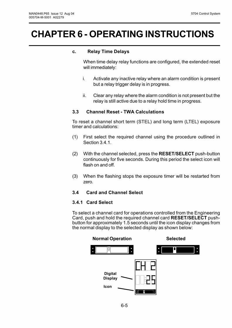
6-5
MAN0448.P65 Issue 12 Aug 04 5704 Control System005704-M-5001 A02279
CHAPTER 6 - OPERATING INSTRUCTIONS
c. Relay Time Delays
When time delay relay functions are configured, the extended resetwill immediately:
i. Activate any inactive relay where an alarm condition is presentbut a relay trigger delay is in progress.
ii. Clear any relay where the alarm condition is not present but therelay is still active due to a relay hold time in progress.
3.3 Channel Reset - TWA Calculations
To reset a channel short term (STEL) and long term (LTEL) exposuretimer and calculations:
(1) First select the required channel using the procedure outlined inSection 3.4.1.
(2) With the channel selected, press the RESET/SELECT push-buttoncontinuously for five seconds. During this period the select icon willflash on and off.
(3) When the flashing stops the exposure timer will be restarted fromzero.
3.4 Card and Channel Select
3.4.1 Card Select
To select a channel card for operations controlled from the EngineeringCard, push and hold the required channel card RESET/SELECT push-button for approximately 1.5 seconds until the icon display changes fromthe normal display to the selected display as shown below:
Normal Operation Selected
DigitalDisplay
Icon

6-6
MAN0448.P65 Issue 12 Aug 04 5704 Control System005704-M-5001 A02279
CHAPTER 6 - OPERATING INSTRUCTIONS
3.4.2 Channel Select
Once a card has been selected, a particular channel can then be selectedby using the ( ) and ( ) push-buttons on the Engineering Card. Theselected channel number will be shown on the message display.
3.5 Deselect
3.5.1 Card Deselect
To deselect a selected channel card, briefly push its front panel RESET/SELECT push-button.
The channel card will be deselected and any user operations in progresswhich have not been confirmed will be cancelled. It should be noted thatthe channel card will not be reset unless the RESET/SELECT push-button is again momentarily pushed.
3.5.2 Card Deselect with Channel Display Lock
If the control card has been configured for a sequential channel displaymode, it is possible to lock the display to a particular channel bydeselecting the card using the push-button.
To lock the display to a particular channel:
(1) Select the required channel as indicated in Section 3.4.2.
(2) Briefly press the push-button and the select icon will clear.
The channel display will remain locked to the desired channel until thecard is next reset or selected.
4. ENGINEERING CARD
4.1 General
The Engineering Card push-button functions will only operate if a channelcard is selected. See Section 3.3.
Without the Engineering Key fitted to the Engineering Card, the followingEngineering Card push-buttons will not be available:
Inhibit
Zero
Span
1st Span
If any of these push-buttons are pushed, a locked symbol ( ) will bebriefly displayed on the selected channel card message display.

6-7
MAN0448.P65 Issue 12 Aug 04 5704 Control System005704-M-5001 A02279
CHAPTER 6 - OPERATING INSTRUCTIONS
4.2 Timeout
When operating the Engineering Card without an Engineering Key fittedthere is a timeout period of 30 seconds. If no push-buttons are pressedwithin the timeout period, the selected channel card will automatically bedeselected.
4.3 Bargraph Display
When operating the Engineering Card without an Engineering Key fitted,the selected channel's bargraph display will continue to indicate theactual gas reading during the operation of the available EngineeringCard functions.
4.4 Catalytic Sensor Bridge Current
The operation associated with the BEAD mA push-button only applies tocatalytic channel cards. Operating this push-button with other types ofchannel cards selected has no effect and the warning message (XXXX)is displayed for a short time.
To enter the catalytic sensor bridge current operation, proceed as follows:
(1) Push and hold the required channel card RESET/SELECT push-button for approximately 1.5 secondsuntil the selected icon appears on the channel display.
(2) Use the Engineering Card ( ) and ( ) push-buttons toselect the required channel.
(3) Push the BEAD mA push-button and the selectedchannel card display will indicate the configured bridgecurrent. eg. 200mA alternating with the selected channelnumber.
(4) Push the reject ( ) push-button or wait 30 seconds toexit the Bead mA mode.
4.5 View Alarm Level Settings
The operation of the ALARMS push-button allows the viewing of thealarm threshold point and alarm type (rising or falling) for each alarm setpoint A1, A2 and A3.
To enter the alarm view operation, proceed as follows:

6-8
MAN0448.P65 Issue 12 Aug 04 5704 Control System005704-M-5001 A02279
CHAPTER 6 - OPERATING INSTRUCTIONS
(1) Push and hold the required channel card RESET/SELECT push-button for approximately 1.5 seconds until the selected icon appearson the channel display.
(2) Use the Engineering Card ( ) and ( ) push-buttons to select therequired channel.
(3) Push the ALARMS push-button and the selected channelcard display will indicate the A1 level alarm alternatingwith the selected channel number as indicated opposite.
Note: The up arrow indicates a rising alarm while thedown arrow indicates a falling alarm.
(4) Push the ALARMS push-button a second time and theselected channel card display will indicate the A2 levelalarm.
Note: Step (5), (6) and (7) will only be available if the controlcard is configured for the stated alarm.
(5) Push the ALARMS push-button a third time and theselected channel card display will indicate the A3. level alarm.
(6) Push the ALARMS push-button a fourth time and the selected channelcard display will indicate the STEL level alarm.
(7) Push the ALARMS push-button a fifth time and the selected channelcard display will indicate the LTEL level alarm.
(8) Further pushes of the ALARMS push-button will scroll through thealarm level set points again.
(9) Push the ( ) or ( ) push-buttons or wait 30 seconds to exit theALARMS mode.
4.6 Sensor Signal Monitoring
The operation of the SIGNAL push-button allows the monitoring of theselected channels sensor signal value. The displayed parameter isdependent upon the type of selected channel card.
To enter the sensor signal monitoring operation, proceed as follows:

6-9
MAN0448.P65 Issue 12 Aug 04 5704 Control System005704-M-5001 A02279
CHAPTER 6 - OPERATING INSTRUCTIONS
(1) Push and hold the required channel card RESET/SELECT push-button for approximately 1.5 seconds until the selected icon appearson the channel display.
(2) Use the Engineering Card ( ) and ( ) push-buttons to select therequired channel.
(3) Push the SIGNAL push-button and the selected channel card displaywill indicate the sensor signal alternating with the selected channelnumber. The displayed value will depend on the type of control cardfitted as follows:
a. Four Channel Control Card - Catalytic
The display will show the live bridgevoltage measured between 01 and 02in mV. 02 is the centre point of thesecond half of the Wheatstone bridgewhich is on the channel card.
b. Four Channel Control Card - 4 - 20mA
The display will show the live sensorloop current in mA.
(4) Push the ( ) or ( ) push buttons or wait 30seconds to exit the SIGNAL mode.
4.7 View Clock/Calendar
The operation of the CLOCK push-button will cause the present time anddate to be displayed on a selected channel card.
Note: This operation requires a control card to be selected but theoperation has no effect on the selected control card, which is usedas a display device only.
To enter the clock/calendar operation, proceed as follows:
(1) Push and hold the required channel card RESET/SELECT push-button for approximately 1.5 seconds until the selected icon appearson the channel display.

6-10
MAN0448.P65 Issue 12 Aug 04 5704 Control System005704-M-5001 A02279
CHAPTER 6 - OPERATING INSTRUCTIONS
(2) Push the CLOCK push-button and theselected channel card display will indicatethe present time alternating with the selectedchannel number.
Note: The clock uses the 24 hour format.
(3) Push the CLOCK push-button a second timeand the selected channel card display willindicate the present day, month and yearalternating with the selected channel number.
Note: 1. The display format for day andmonth can read either DD.MM or MM.DD depending on theconfiguration of the system.
2. Further pushes of the CLOCK push-button will toggle thedisplay between time and date.
(4) Push the ( ) or ( ) push-buttons or wait 30 seconds to exit theCLOCK mode.
4.8 Maintenance Record Print Out
A detailed printout of the status for each channel or a summary of thewhole rack can be initiated using the Engineering Card. The data is fedin ASCII text format to the engineering serial port on the EngineeringCard front panel.
To output the maintenance record for each channel card, proceed asfollows:
(1) Plug a RS232 printer into the Engineering card serial port.
(2) Push and hold the required channel card RESET/SELECT push-button for approximately 1.5 seconds until the selected icon appearson the channel display.
(3) Use the Engineering Card ( ) and ( ) push-buttons to select therequired channel.
(4) Push the up ( ) and down ( ) buttons simultaneously. The selectedchannel card will display PRN while outputting the following data:

6-11
MAN0448.P65 Issue 12 Aug 04 5704 Control System005704-M-5001 A02279
CHAPTER 6 - OPERATING INSTRUCTIONS
17/10/96 1:42Slot : 04.3Card Type : 5704Sensor Type : 4 - 20mAS/W : v01.00Serial Number : 01234A02Range : 0 - 100Units : LELSensor : 780Gas : MethaneTag : Vent 04First Span : 10/04/96Last Span : 16/09/96Cal. rem. : 06 monthsA1 : 0025 %fsdA2 : 0050 %fsdA3 : 0076.8 %fsdRelay 01 active low Local events assoc'd to this relay Events : FTRelay 02 active high Local events assoc'd to this relay Events : A1Relay 03 active high Local events assoc'd to this relay Events : A2Relay 04 active high Local events assoc'd to this relay Events : A3Relay 12 active high Local events assoc'd to this relay Events : A3Relay 13 active high Local events assoc'd to this relay Events : A2Relay 14 active high Local events assoc'd to this relay Events : A1Relay 15 active high Local events assoc'd to this relay Events : INRelay 16 active high Local events assoc'd to this relay Events : FTComplex update activates relays: 13Update assoc'd with the followingEvents : A3 A2 A1
Note: 1. The information printed will vary slightly depending on thetype of control card fitted.
2. If an RS232 device is not connected or is not able to acceptcharacters, the selected control card display will show XXXX.

6-12
MAN0448.P65 Issue 12 Aug 04 5704 Control System005704-M-5001 A02279
CHAPTER 6 - OPERATING INSTRUCTIONS
To output a summary of the whole rack, proceed as follows:
(1) Plug an RS232 printer into the Engineering Card serial port.
(2) Push the up ( ) and down ( ) buttons simultaneously without anychannel card being selected and the following data will be printed:
15/08/96 12:05Type : Engineering CardS/W : v00.70Eng key override : inactiveCustomer name :DMTCustomer site :EssenSerial No : 01234A17--Slot : 01Type : 5704S/W : v01.00Serial No : 01234A01Tag : UnknownGas : UnknownRange : 0 - 100Active alarms : FT--Slot : 02Type : 5704S/W : v01.00Serial No : 01234A02Tag : 23C-03Gas : MethaneRange : 0 - 100Active alarms : A1--Slot : 12Type : 5701S/W : v00.75Serial No : 01234A12Tag : UnknownGas : UnknownRange : 0 - 100Active alarms : None
Note: The information printed will vary slightly depending on the type ofcontrol card fitted.

7-1
MAN0448.P65 Issue 12 Aug 04 5704 Control System005704-M-5001 A02279
CHAPTER 7 - ENGINEER'S OPERATINGINSTRUCTIONS
5704 SERIES
CONTROL SYSTEM
CHAPTER 7
ENGINEER'S
OPERATING INSTRUCTIONS

7-2
MAN0448.P65 Issue 12 Aug 04 5704 Control System005704-M-5001 A02279
CHAPTER 7 - ENGINEER'S OPERATINGINSTRUCTIONS
CONTENTS
Section Page
1. General 7-3
2. Engineering Operating Routines 7-3
3. Unlocking the Engineering Card 7-4
4. Selected Card Operations 7-4
5. Channel Inhibit 7-5
6. Alarm Configuration and Relay Test 7-6
7. Catalytic Sensor Bridge Current Adjustment 7-9
8. Zero Signal Calibration 7-10
9. Span Signal Calibration 7-11
10. First Time Span Signal Calibration 7-13
11. Sensor Signal Monitoring 7-13
12. Setting the Clock/Calendar 7-14
13. Maintenance Operating Routines 7-15

7-3
MAN0448.P65 Issue 12 Aug 04 5704 Control System005704-M-5001 A02279
CHAPTER 7 - ENGINEER'S OPERATINGINSTRUCTIONS
1. GENERAL
The engineer's operating instructions refer to the additional facilitiesavailable to setup and maintain the system. Because the operation of thesystem can be altered or impeded by these functions, they can only beperformed when the Engineering Card is unlocked by the EngineeringKey.
2. ENGINEERING OPERATING ROUTINES
Depending upon the which keypad function push-button is operated, thefollowing engineering operating routines may be carried out:
Channel Reset.
Channel Select.
Channel Inhibit.
Alarm Configuration and Relay Test.
Catalytic Bridge Current Adjustment.
Zero Signal Calibration.
Span Signal Calibration.
1st Span Signal Calibration.
Sensor Signal Monitoring.
Clock/Calendar Adjustment.
Channel select and reset are carried out by the channel card RESET/SELECT push-button. See Chapter 6, Section 3.
The remaining engineering functions are carried out after a control cardhas been selected using the Engineering Card push-button controls.

7-4
MAN0448.P65 Issue 12 Aug 04 5704 Control System005704-M-5001 A02279
CHAPTER 7 - ENGINEER'S OPERATINGINSTRUCTIONS
3. UNLOCKING THE ENGINEERING CARD
To unlock the Engineering Card, plug the Engineering Key into theEngineering Card front panel socket. The Engineering Card UnlockedLED ( ) will illuminate to indicate that it is unlocked.
External Engineering Port Engineering Key
Note: Inserting and then removing the Engineering Key resets theEngineering Card communications failure warning indication.
4. SELECTED CARD OPERATIONS
The operation to be carried out on the selected control card channel ischosen by pushing one of the following Engineering Card control push-buttons:
Once an operation has been selected, there are four control push-buttonswhich may be used to manipulate the operation as required. These are:
a. The up push-button, which may be used to raise the selectedcontrol card indicted value. If held in the operated position, thedisplay will be increased by one unit every 0.5 seconds.
b. The down push-button, which may be used to lower the selectedcontrol card indicated value. If held in the operated position, thedisplay will be decreased by one unit every 0.5 seconds.
c. The accept push-button, which may be used to accept theselected control card displayed value and store this permanentlyas part of the configuration. Returns the control card to theselected mode.
Bead mA
ZERO
SPAN
INHIBIT
ALARMS
SIGNAL
1st SPAN
CLOCK

7-5
MAN0448.P65 Issue 12 Aug 04 5704 Control System005704-M-5001 A02279
CHAPTER 7 - ENGINEER'S OPERATINGINSTRUCTIONS
d. The reject push-button, which may be used to reject the selectedcontrol card displayed value and return to the previous set value.Returns the control card to the selected mode.
5. CHANNEL INHIBIT
Pushing the Engineering Card INHIBIT push-button toggles the selectedcontrol card channel inhibit mode between on and off.
When the inhibit mode is set to on, either locally from the EngineeringCard or remotely by the Remote Inhibit input, the selected control card:
a. channel inhibit relay, if configured, is actuated.
b. channel LED shows continuous amber to indicate INHIBIT.
c. remaining channel relays are locked in their non-active state.
To select the inhibit function, proceed as follows:
(1) Plug the Engineering Key into the Engineering Card front panelsocket and check that the Unlocked LED ( ) is illuminated.
(2) Push and hold the required control card RESET/SELECT push-button for approximately 1.5 seconds and check that the selectedcontrol card indicates it has been selected by displaying the selecticon.
(3) Use the Engineering Card ( ) and ( ) push-buttons to select therequired channel.
(4) Push the INHIBIT push-button to toggle the channels inhibit mode on/off.
INHIBIT

7-6
MAN0448.P65 Issue 12 Aug 04 5704 Control System005704-M-5001 A02279
CHAPTER 7 - ENGINEER'S OPERATINGINSTRUCTIONS
6. ALARM CONFIGURATION AND RELAY TEST
The alarm configuration and relay test operation cycles through differentstages as follows:
a. Set thresholds for A1, A2, A3, STEL, LTEL.
These stages are used to set the A1, A2, A3, STEL and LTEL alarmthreshold points and do not affect the alarm LEDs and relays.
b. Test lamps and optional relays for A1, A2, A3, Fault, STEL, LTEL.
These stages provide a lamp test and relay test function.
Note: When not configured for STEL/LTEL threshold, a row of dasheswill be displayed instead of a level and the STEL and LTEL faclilitieswill be set permanently to off.
To select the alarm configuration operation, proceed as follows:
(1) Plug the Engineering Key into the Engineering Card front panelsocket and check that the Unlocked LED ( ) is illuminated.
(2) Push and hold the required control card RESET/SELECT push-button for approximately 1.5 seconds and check that the selectedcontrol card indicates it has been selected by displaying the selecticon.
(3) Use the Engineering Card ( ) and ( ) push-buttons to select therequired channel.
(4) Push the Engineering Card ALARMS push-button for the first time.
(5) Check that the selected control card message display shows A1 fora rising alarm threshold or A1 for a falling alarm threshold alternatingwith the selected channel number.
(6) Check that the selected control card digital display indicates the A1alarm threshold point.
Note: The analogue display continues to show the sensor livemeasurement.
ALARMS

7-7
MAN0448.P65 Issue 12 Aug 04 5704 Control System005704-M-5001 A02279
CHAPTER 7 - ENGINEER'S OPERATINGINSTRUCTIONS
(7) If required, use the ( ) and ( ) push-buttons to set a new A1 alarmthreshold point.
Note: The threshold level can only be set to a level that is between thehigh and low points set in the Control Card configuration.
(8) When the correct level has been set, and if no more adjustments arerequired, push the push-button to set the new level and store thispermanently. Otherwise proceed to the next step.
Note: If it is required to cancel the procedure at any time without alteringthe original setting to the displayed value, press the pushbutton.
(9) Push the Engineering Card ALARMS push-button a second time andrepeat Steps (5) to (8) for the A2 threshold points setting.
(10) Push the Engineering Card ALARMS push-button a third time andrepeat Steps (5) to (8) for the A3 threshold points setting.
(11) Push the Engineering Card ALARMS push-button a fourth time andrepeat Steps (5) to (8) for the STEL threshold points setting.
(12) Push the Engineering Card ALARMS push-button a fifth time andrepeat Steps (5) to (8) for the LTEL threshold points setting.
(13) Push the Engineering Card ALARMS push-button for a sixth time andTEST will be displayed on the message display alternating with theselected channel number. Initially the A1 level of the selected channelis displayed on the digital and analogue displays and the associatedCHL LED is illuminated at the A1 Alarm rate. The ATTN LED will alsobe lit.
(14) Use the ( ) and ( ) push-buttons to raise or lower the simulated gaslevel over a range of levels that includes the A1, A2, A3 and underrangeFault values. Check that the selected control card indicates thesimulated gas level on the analogue and digital display, and that theappropriate alarm states are indicated on the selected channel LED.
(15) Push the Engineering Card ALARMS push-button for a seventh timeand STEL will be displayed on the message display alternating withthe selected channel number. The digital display will indicate OFFindicating the channel is in the STEL test mode but the STEL alarm isswitched off.

7-8
MAN0448.P65 Issue 12 Aug 04 5704 Control System005704-M-5001 A02279
CHAPTER 7 - ENGINEER'S OPERATINGINSTRUCTIONS
(16) If required, use the Engineering Card ( ) and ( ) push-buttons toswitch the STEL on.
Note: The STEL Alarm can only be switched on if the Control Card hasbeen configured for this alarm.
(17) Push the Engineering Card ALARMS push-button for a eighth timeand LTEL will be displayed on the message display alternating withthe selected channel number. The digital display will indicate OFFindicating the channel is in the LTEL test mode but the LTEL alarm isswitched off.
(18) If required, use the Engineering Card ( ) and ( ) push-buttons toswitch the LTEL on.
Notes: 1. The LTEL Alarm can only be switched on if the Control Cardhas been configured for this alarm.
2. The TEST function automatically inhibits the control cardchannel to allow a display test and a lamp test of the channelLED alarm indications and prevent accidental alarms beinggenerated. In order to test the relays and FAULT indications,the INHIBIT push-button must be used to set the control cardchannel into the uninhibited state.
3. A selected control card may be deselected while in the TESTmode by pushing the selected control card front panel RESET/SELECT push-button. The simulated gas level and relaystates will remain set allowing several control cards to betested simultaneously. When the control card is reselectedthe card will return to the TEST mode. The ATTN LED indicateswhich cards have channels in the alarm test mode.
4. If the inhibit is removed, the external relays will operate.
IMPORTANT
When the TEST mode is used, always ensure that the channel controlcard is returned to the uninhibited state after the test.

7-9
MAN0448.P65 Issue 12 Aug 04 5704 Control System005704-M-5001 A02279
CHAPTER 7 - ENGINEER'S OPERATINGINSTRUCTIONS
7. CATALYTIC SENSOR BRIDGE CURRENTADJUSTMENT
The operation associated with the BEAD mA push-button only applieswhen a catalytic control card has been selected. The pressing of thepush-button with other types of control cards selected has no purposeand a warning (XXXX) is displayed to this effect.
To enter the catalytic sensor bridge current operation, proceed as follows:
(1) Plug the Engineering Key into the Engineering Card front panelsocket and check that the Unlocked LED ( ) is illuminated.
(2) Push and hold the required control card RESET/SELECT push-button for approximately 1.5 seconds and check that the selectedcontrol card indicates it has been selected by displaying the selecticon.
(3) Use the Engineering Card ( ) and ( ) push-buttons to select therequired channel.
(4) Push the Engineering Card BEAD mA push-button and check that the selected controlcard message display shows mA alternatingwith the selected channel number. and thedigital display shows the actual bridgecurrent.
(5) If the displayed bridge current is not set tothe required value, use the ( ) and ( ) push-buttons to raise orlower the indicated bridge current reading until the required value isdisplayed.
Note: Pressing the push-button will cancel the displayed current withoutalteration to the stored value.
(6) Push the push-button to permanently set the new bridge current.The selected control card channel will then automatically return to thenormal selected state.
BEAD mA

7-10
MAN0448.P65 Issue 12 Aug 04 5704 Control System005704-M-5001 A02279
CHAPTER 7 - ENGINEER'S OPERATINGINSTRUCTIONS
8. ZERO SIGNAL CALIBRATION
To select the zero operation, proceed as follows:
(1) Plug the Engineering Key into the Engineering Card front panelsocket and check that the Unlocked LED ( ) is illuminated.
(2) Push and hold the required control card RESET/SELECT push-button for approximately 1.5 seconds and check that the selectedcontrol card indicates it has been selected by displaying the selecticon.
(3) Use the Engineering Card ( ) and ( ) push-buttons to select therequired channel.
(4) Push the Engineering Card ZERO push-button and the EngineeringCard will automatically inhibit the selected control card channel toprevent false alarms being generated. One of the following displayswill be shown on the selected control message display:
a. Indicates a stable gas reading.
b. Indicates a rising gas reading.
c. Indicates a falling gas reading.
(5) Check that the selected control card digital display andbargraph continue to display the current sensor signallevel.
Note: Pushing the push-button at this stage will return the control cardto the selected mode without any changes to the original zeroreading.
(6) Ensure the selected channel sensor is in a gas free atmosphere. Ifrequired apply zero gas, normally air not containing the gas to bemeasured, at the flow rate and for a time according to the selectedchannels sensor instruction manual.
(7) When the message display shows , to indicate a stablereading, push the push-button.
ZERO

7-11
MAN0448.P65 Issue 12 Aug 04 5704 Control System005704-M-5001 A02279
CHAPTER 7 - ENGINEER'S OPERATINGINSTRUCTIONS
(8) The selected control card will display oooo on the message displaywhile the Control Card carries out the following:
a. Zeroes itself at the current sensor signal, providing this is withinthe configured upper and lower zero signal limit values. Thecontrol card will then automatically return to the normal selectedstate.
b. If the signal is outside the stored signal limits an error messagewill be displayed on the selected control card display.
c. Automatically return to the normal selected state, however, theinhibit on the control card channel will remain active.
(8) If the Span Signal Calibration (Section 9) is not to follow this procedure,remove the inhibit.
9. SPAN SIGNAL CALIBRATION
Note: If a new sensor is being calibrated for the first time, use the 1stSpan procedure in Section 10.
To select the span operation, proceed as follows:
(1) Plug the Engineering Key into the Engineering Card front panelsocket and check that the Unlocked LED ( ) is illuminated.
(2) Push and hold the required control card RESET/SELECT push-button for approximately 1.5 seconds and check that the selectedcontrol card indicates it has been selected by displaying the selecticon.
(3) Use the Engineering Card ( ) and ( ) push-buttons to select therequired channel.
(4) Push the Engineering Card SPAN push-button and theselected control card channel will automatically beinhibited and one of the following displays will be shownon the control card message display:
a. Indicates a stable gas reading.
b. Indicates a rising gas reading.
c. Indicates a falling gas reading.
SPAN

7-12
MAN0448.P65 Issue 12 Aug 04 5704 Control System005704-M-5001 A02279
CHAPTER 7 - ENGINEER'S OPERATINGINSTRUCTIONS
(5) Check that the selected control card digital display indicates therequired span gas concentration to be used, if not, use the ( ) and( ) push-buttons to raise or lower the indication until the correctconcentration is displayed.
Note: 1. The analogue display will continue to show the current sensorlive signal level.
2. Pushing the button at this stage will return the control card tothe selected mode without any changes to the original spansetting.
(6) Apply the span gas at a flow rate and for a time according to theselected channels sensor instruction manual.
Note: 1. Apart from oxygen, every sensor should be zeroed beforebeing spanned. See Section 8.
2. Although a Span Gas as low as 15% of the fsd value of thesensor may be used, it is recommended that a value of 40%or above is used.
(7) When the message display shows to indicate a stablereading, push the push -button. The selected control card will thendisplay on the digital display while it carries out the following:
a. Adjusts its span calibration parameter to the new displayedvalue, providing this is within the configured upper and lowerspan signal limit values.
b. Set the last calibration date to the current date and reset thecalibration reminder if this is enabled.
c. Automatically return to the normal selected state, however, theinhibit on the control card channel will remain active.
d. If the displayed value is outside the stored signal limits, displayan error message.
e. On control cards for catalytic sensor inputs, the present sensorsignal will be compared with that recorded when the sensor wasnew. A warning will be displayed if the sensitivity of the sensorhas fallen to below 50% of its original value.

7-13
MAN0448.P65 Issue 12 Aug 04 5704 Control System005704-M-5001 A02279
CHAPTER 7 - ENGINEER'S OPERATINGINSTRUCTIONS
IMPORTANT
When the span gas has been removed and the sensor signal hasreturned to normal, do not forget to return the control card channel to itsuninhibited state.
10. FIRST TIME SPAN SIGNAL CALIBRATION
When the 1st SPAN push-button is pressed, the operation of the selectedcontrol card channel is similar to when the SPAN push-button is pressed.
To carry out the first time span calibration, proceed as indicated inSection 9 Steps (1) to (6) but push the 1st SPAN push-button.
Note: 1. In Step (6) when the span calibration is updated, the newsensor calibration date and the last sensor calibration date willboth be set to the current date.
2. On control cards for catalytic sensor inputs, the sensor spansignal value is recorded as the new sensor value. This valuewill be used to provide sensor life monitoring data bycomparison with subsequent values obtained during latercalibrations using the SPAN button.
11. SENSOR SIGNAL MONITORING
The operation of the SIGNAL push-button allows the monitoring of theselected channels sensor signal value. The displayed parameter isdependent upon the type of control card.
To enter the sensor signal monitoring operation, proceed as follows:
(1) Push and hold the required channel card RESET/SELECT push-button for approximately 1.5 seconds until the selected icon appearson the channel display.
(2) Use the Engineering Card ( ) and ( ) push-buttons to select therequired channel.
(3) Push the SIGNAL push-button and the selected channel card displaywill indicate the sensor signal. The displayed value will depend on thetype of sensor drive module fitted to the channel card as follows:
1st SPAN
SIGNAL

7-14
MAN0448.P65 Issue 12 Aug 04 5704 Control System005704-M-5001 A02279
CHAPTER 7 - ENGINEER'S OPERATINGINSTRUCTIONS
a. Four Channel Control Card - Catalytic
The display will show the live bridge voltagemeasured between 01 and 02 in mV. 02 is thecentre point of the second half of the Wheatstonebridge which is on the channel card.
b. Four Channel Control Card - 4 - 20mA
The display will show the live sensor loop current inmA.
(4) No alterations can be made to the above readings andpressing either the or push-buttons will return theselected control card to the selected mode.
12. SETTING THE CLOCK/CALENDAR
Note: This operation requires a control card to be selected but theoperation has no effect on the selected control card, which is usedas a display device only.
To set the clock time and calendar date, proceed as follows:
(1) Plug the Engineering Key into the Engineering Card front panelsocket and check that the Unlocked LED ( ) is illuminated.
(2) Push and hold the required control card RESET/SELECT push-button for approximately 1.5 seconds and check that the selectedcontrol card indicates it has been selected by displaying the selecticon.
(3) Push the Engineering Card CLOCK push-button and theselected control card digital display will show the time ofday (eg. 23:59) with the HOURS value flashing.
(4) Push the Engineering Card CLOCK push-button asecond time and the selected control card digital displaywill display the time of day (eg. 23:59) with the MINUTESvalue flashing.
CLOCK

7-15
MAN0448.P65 Issue 12 Aug 04 5704 Control System005704-M-5001 A02279
CHAPTER 7 - ENGINEER'S OPERATINGINSTRUCTIONS
(5) Push the Engineering Card CLOCK push-button a third time and theselected control card will display:
a. The year (eg. 1995) on the message display(flashing).
b. The month and day (eg. 08-26) or day and month(eg. 26-08) on the digital display depending uponthe international date format configuration.
(6) Subsequent pushes of the CLOCK push-button will cause the monthand then the day to flash.
(7) Further pushes of the CLOCK push-button will repeat Steps (3) to (6).
(8) At each stage, use the ( ) and ( ) push-buttons to raise or lower thedisplayed numerical value as required to set any new date and time.
Note: Pressing the push-button at any time during the above sequencewill return the Engineering Card to the selected mode withoutchanging the clock time and calendar date.
(9) Press the push-button to set the Engineering Card real time clockto the new date and time, and return the control card to the selectedmode.
13. MAINTENANCE RECORD PRINTOUTS
For details of the maintenance record printouts, refer to Chapter 6 Section4.8.

7-16
MAN0448.P65 Issue 12 Aug 04 5704 Control System005704-M-5001 A02279
CHAPTER 7 - ENGINEER'S OPERATINGINSTRUCTIONSUSER NOTES
8-1
MAN0448.P65 Issue 12 Aug 04 5704 Control System005704-M-5001 A02279
CHAPTER 8 - SPECIFICATION
5704 SERIES
CONTROL SYSTEM
CHAPTER 8
SPECIFICATION

8-2
MAN0448.P65 Issue 12 Aug 04 5704 Control System005704-M-5001 A02279
CHAPTER 8 - SPECIFICATION
CONTENTS
SectionPage
1. APPROVALS AND STANDARDS 8-3
2. ENVIRONMENTAL 8-3
3. RFI/EMC CONFORMITY 8-3
4. POWER SUPPLIES 8-4
5. INDIVIDUAL MODULE PARAMETERS 8-4
5.1 Quad Relay Interface Card 8-45.2 Relay Interface Assembly 8-45.3 Four Channel Control Card - General 8-55.4 Four Channel Control Card - Catalytic 8-65.5 Four Channel Control Card - 4 - 20mA 8-75.6 Analogue Output Module 8-75.7 Engineering Card 8-85.8 DC Input Card 8-8
6. CABINET ASSEMBLIES 8-9
7. RACK ASSEMBLIES 8-10
8. POWER SUPPLY UNITS 8.12

8-3
MAN0448.P65 Issue 12 Aug 04 5704 Control System005704-M-5001 A02279
CHAPTER 8 - SPECIFICATION
1. APPROVALS AND STANDARDS
Designed to comply with:
EN50054 General Requirements (Combustible Gases).EN50057 Performance (100 LEL).EN50058 Performance (100 V/V).EN50271 Software and Digital Technologies.
Meets Exe isolation requirements for 50V operation.
EXAM BBG Pruef- und Zertifizier GmbH, EC-type examination certificateBVS 04 ATEX G 001 X
Note: If compliance with the EC-type examination certificate BVS 04ATEX G 001 X is required, refer to chapter 10 ‘Special Conditionsfor Safe Use’. Ensure that all conditions therein are met.
2. ENVIRONMENTAL
Operating Temperature: -5OC to +55OC.(*0OC for EXAM approved systems)
Storage Temperature: -25OC to +55OC.Humidity: 0 to 90% RH. Non-condensing.
3. RFI/EMC CONFORMITY
EMC Directive 89/336/EEC
Conforms to:
EN50270:1999 EMC/RFI (Generic Emission)..
Radiated Susceptibility: 10V/m over 50kHz to 1GHz.
LV Directive 73/23/EEC
Constructed in accordance with good engineering practice. Guided bythe principles of EN 61010/1 1990/1992.

8-4
MAN0448.P65 Issue 12 Aug 04 5704 Control System005704-M-5001 A02279
CHAPTER 8 - SPECIFICATION
4. POWER SUPPLIES
Power Consumption : Dependent upon configuration.(System) See Chapter 4, Section 5.
External DC Power Supply: 18V to 32V to DC Input Card.
External AC Power Supply: 85V to 264V at 47Hz to 440Hz.(Using optional AC to DC PSU).
5. INDIVIDUAL MODULE PARAMETERS
5.1 Quad Relay Interface Card (05704-A-0121)
Dimensions: Height 132mm.Width 25mm.Depth 119mm.
Weight: 230g.
Power: 1.7W (maximum) 1W (typical).
Relays: 4 x SPCO.
Relay Operation: Selectable.Latching/Non-Latching.Energised/De-Energised.
Relay Contact Rating: 5A at 110V/250V ac (non inductive).5A at 32V dc (non- inductive).
Field Terminals: 2.5mm2 (14 AWG).
5.2 Relay Interface Assembly (05704-A-0131)
Consists of a Expansion Relay Card fitted to a Quad Relay InterfaceCard.
Dimensions: Height 132mm.Width 52mm.Depth 122mm.
Weight: 500g.
Power: 6.5W (maximum) 3.5W (typical).
Relays: 12 x SPCO.4 x SPST.

8-5
MAN0448.P65 Issue 12 Aug 04 5704 Control System005704-M-5001 A02279
CHAPTER 8 - SPECIFICATION
Relay Operation: Selectable.Latching/Non-Latching.Energised/De-Energised.
Relay Contact Rating: 5A at 110V/250V ac (non inductive).5A at 32V dc (non- inductive).
Field Terminals: 2.5mm2 (14 AWG).
5.3 Four Channel Control Card - General
Four-Part Liquid Display:
Analogue Display: 25 segment.Digital Display: Four character.Message Display: Four character.Icon Section: Power On/Card Select.
LED Indicators: CHL 1, CHL 2, CHL 3, CHL 4 and ATTN.
CHL Indicators: Two colour amber / red providing warnings of:
A1 Alarm: 1 quick red flash per second.A2 Alarm: 2 quick red flashes per second.A3 Alarm: 3 quick red flashes per second.STEL, LTEL Slow red flash, 1 second on 1 second off.
Fault: Flashing amber.
Inhibit: Steady amber.
ATTN Indicator:
Hardwareor Software Fault: Slow flashing amber.
Update AlarmCondition: Fast flashing amber.
Alarm Test: Steady amber.
Push-Button: Alarm Reset/Card Select.
Initial accuracy: ±1%.
Alarm Setting PointResolution: In 1% fsd steps.

8-6
MAN0448.P65 Issue 12 Aug 04 5704 Control System005704-M-5001 A02279
CHAPTER 8 - SPECIFICATION
Display/Alarm Point:
Linearity: ±2% fsd.Repeatability: ±2% fsd.
Remote Facilities: Inhibit/Alarm Reset.
Remote Inhibit / Reset Inputs
Active For Inputs: More than 2V.
Maximum Input Voltage: 32V.
Maximum Input Current: 5mA.
DC Supply: 18V to 32V dc.
Electronic Drift: Less than ±3% / 6 months.
Dimensions: Height: 132mm.Width: 25mm.Depth: 172mm.
Weight: 170g.
5.4 Four Channel Control Card - Catalytic
Power Consumption: 12.8W (maximum at 200mA sensorcurrent).
8.5W (typical).
Drive: Constant Current.
Initial Accuracy: ±1%.
Current Adjustment: Electronic in 1mA stepsfrom 90 to315mA.
Maximum Drive Voltage: 10V.
Protection: Protected against short circuit andopen circuit.
Maximum Line Resistance: 40 ohms (including sensor) at 200mA.
Full Scale Signal Range: 15mV to 300mV.
Bridge Imbalance Default Limits: ±100mV from centre at 2V bridgevoltage.
Adjustment: Electronic adjustment of bridgebalance and signal gain.

8-7
MAN0448.P65 Issue 12 Aug 04 5704 Control System005704-M-5001 A02279
CHAPTER 8 - SPECIFICATION
Fault Detection: Open circuit.Short circuit single bead failure.
Over-Range Default: +10% above fsd.
Under-Range Default: -10% below zero.
5.5 Four Channel Control Card - 4 - 20mA
Power Consumption: 8.3W (maximum). 7.5W (typical).
Loop Powered Output Voltage: Isolated 24V ± 5% regulated, 25mAmaximum for loop powered devices.
Transmitter Supply OutputVoltage: None.
Loop Protection: Short circuit, open circuit voltage of±50V.
Configuration: Sensor current source.
Measurement Signal Range: 0 to 25mA.
Maximum Line Resistance: 500 ohms loop resistance includingsensor.
Isolation Breakdown Voltage: More than ±50V dc to system 0V.
5.6 Analogue Output
Output Compliance Range: 40V.
Protection: Short circuit protected.Reverse voltage up to 36V dc.Transient voltage of less than 60V dc.
Configuration: Isolated current sink/source with 18 -40Vexternal supply.
Signal Range: 0 - 25mA.
Measurement Signal Range: 0 - 20mA or 4 - 20mA selected by thesoftware.
Linearity From Input: Better than ±2% fsd.
Repeatability From Input: Better than ±1% fsd.
Isolation BreakdownVoltage: More than ±50V dc to system 0V.

8-8
MAN0448.P65 Issue 12 Aug 04 5704 Control System005704-M-5001 A02279
CHAPTER 8 - SPECIFICATION
5.7 Engineering Card
LEDs: Power On ( - Green LED).
Unlocked ( - Red LED).
Push-Button:
Operating: Up ( ) and Down ( ).Reject ( ) and Accept ( ).Print (Up and Down together).
Functions: Bead mA AlarmsZero SignalSpan 1st SpanInhibit Clock
Power Consumption: 1.5W (typical). See rack details.
DC Supply: 18V to 32V dc.
Dimensions: Height: 132mm.Width: 25mm.Depth: 170mm.
Weight: 152g.
5.8 DC Input Card
DC Supply: 18V to 32V dc.
Dimensions: Height: 112mm.Width: 25mm.Depth: 102mm.
Weight: 129g.
Fuse Rating: 10A Anti-surge. 11/4 x 1/4 inches.
Field Terminals: 2.5mm˝ (14 AWG).

8-9
MAN0448.P65 Issue 12 Aug 04 5704 Control System005704-M-5001 A02279
CHAPTER 8 - SPECIFICATION
6. CABINET ASSEMBLIES
Material: Mild steel.
Weight: 8-way: 10.0kg16-way: 13.5kg.
Gland Entries: Knock-out.
8-way 2 x M25 6 x PG118 x M20 2 x PG16
16-way 3 x M25 10 x PG1116 x M20 4 x PG16
Cabinet Dimensions:
100
15
100
430
8 way 367mm16 way 570mm
15
All dimensionshown in mm.
Wall Mounting Bracket Hole Locations
630
8 way 33716 way 540
All dimensionshown in mm.
268

8-10
MAN0448.P65 Issue 12 Aug 04 5704 Control System005704-M-5001 A02279
CHAPTER 8 - SPECIFICATION
Hinged: Left hand side.
Lock: Right hand side.
Colour: RAL 7015 slate grey.
Mounting Bracket Holes: 10mm (0.4'') diameter.
Rack Mounting: Universal 19 inch profile.19 inch width and half 19 inch width.
Earthing Points: Main cabinet M6.Door M5.
Mounting Plate: Galvanised steel.
7. RACK ASSEMBLIES
Rack Assemblies Contains: Engineering Card.
DC Input Card.
Interconnect Cable (front access rackonly).
Material: Galvanised steel.
Earthing Point: M5 stud.
Mounting: Universal 19 inch and half width (19 inchmounting).
Power Consumption: 1.5W.
Supply Voltage: 18 to 32V dc.
Cabinet Mounting Brackets
All dimension shown in mm.
9
10.2
36
9
27
15
10

8-11
MAN0448.P65 Issue 12 Aug 04 5704 Control System005704-M-5001 A02279
CHAPTER 8 - SPECIFICATION
Weight: (including Engineering Card and DC Input Card)
16 Way Front Access: 5.8kg.16 Way Rear Access: 4.1kg.8 Way Front Access: 3.9kg.8 Way Rear Access: 2.8kg.
Table of Sizes (mm)
Rack Assembly A B C D E Depth
8 Way Rear Access 279.4 261.9 57.0 37.8 132.5 287.6
8 Way Front Access 279.4 261.9 190.5 37.8 266.0 217.6
16 Way Rear Access 482.6 465.1 57.0 37.8 132.5 287.6
16 Way Front Access 482.6 465.1 190.5 37.8 266.0 217.6
Panel Cutout Clearance
8 Way Width: 247 Height as column E16 Way 450 as column E
A
B
C E
D
A
B
C E
D
(holes 6mmdiameter)

8-12
MAN0448.P65 Issue 12 Aug 04 5704 Control System005704-M-5001 A02279
CHAPTER 8 - SPECIFICATION
8. POWER SUPPLY UNITS
Mounting: Universal 19'' and half 19'' mounting.
Supply Voltage: 85V to 264V ac 47Hz to 440Hz.
110V to 340V dc.(For information on dc input contactZellweger Analytics).
Inrush Current: Typically 30A at 230V input on full loadper 50W Module.
Leakage Current: 0.75mA maximum per 50W Module.
Overload Protection: Operates at more than 105% of ratedfull load and recovers automatically.
Safety Approvals: 50W Module approved to UL1950,IEC950, CSA 22.2 No 234.
Output Voltage: 24V ± 10% dc.
Output Configurations:
Half 19'' Rack: 50W or 100W.
Full 19'' Rack: 50W, 100W, 150W or 200W.
Earthing Point: M5 stud.
Weight:
Half 19'' Rack 50W: 900g.
Full 19'' Rack 50W: 960g.
50W Module: 230g.
Sub Unit: 815g.

8-13
MAN0448.P65 Issue 12 Aug 04 5704 Control System005704-M-5001 A02279
CHAPTER 8 - SPECIFICATION
PSU Assembly A B Clearance
Width Height Depth
8 Way 279.4 261.9 222 41 190
16 Way 482.6 465.1 443 41 190
Dimensions:A
31.8
5.9
43.6
8.4 B
Mounting holes = 7mm

8-14
MAN0448.P65 Issue 12 Aug 04 5704 Control System005704-M-5001 A02279
CHAPTER 8 - SPECIFICATIONUSER NOTES

9-1
CHAPTER 9 - ORDERING INFORMATION
MAN0448.P65 Issue 12 Aug 04 5704 Control System005704-M-5001 A02279
5704 SERIES
CONTROL SYSTEM
CHAPTER 9
ORDERING INFORMATION

9-2
CHAPTER 9 - ORDERING INFORMATION
MAN0448.P65 Issue 12 Aug 04 5704 Control System005704-M-5001 A02279
5701 Control System Parts - Sheet 1
5704 Control System
SYSTEM 57
Input/OutputCards
Four ChannelControl Card
4 - 20mA05704-A-0145
AnalogueOutputModuleSource
04200-A-0146
Event PrintModule Kit
05701-A-0314
Relay InterfaceAssembly
05704-A-013112 x SPCO4 x SPNO
Quad RelayInterface Card05704-A-0121
4 x SPCO
Four ChannelControl Card
Catalytic05704-A-0144
InterconnectingCable
05704-C-0160
BlankingPanel
05701-A-0365
AnalogueOutputModule
Sink04200-A-0145
AnalogueOutputModuleSource
04200-A-0146
AnalogueOutputModule
Sink04200-A-0145
MODBUSInterface Module Kit
Engineering Card05701-A-0361
RS485/RS42205701-A-0312
RS23205701-A-0313
Alarm UpdateModule Kit
05701-A-0309
Alarm UpdatePanel
05701-A-0339

9-3
CHAPTER 9 - ORDERING INFORMATION
MAN0448.P65 Issue 12 Aug 04 5704 Control System005704-M-5001 A02279
Sub Unit05701-A-0441
50W Module05701-A-0440
AC to DCPower Supplies
16-Way05701-A-0405
8-Way05701-A-0406
Racks
16-Way05701-A-0451
8-Way05701-A-0452
CabinetsEngineeringInterface
Kit05701-A-0551
EngineeringInterfaceSoftware
05701-A-0121
EngineeringInterface Lead05701-A-0120
5701 Control System Parts - Sheet 2
8-Way Sub-rack05701-A-0516
Engineering Card05701-A-0361
DC Input Card05701-A-0325
InterconnectingCable
05701-C-0390
Key Kit05701-A-0550
16-Way Sub-rack05701-A-0515
Engineering Card05701-A-0361
DC Input Card05701-A-0325
InterconnectingCable
05701-C-0390
Key Kit05701-A-0550
8-Way Sub-rack05701-A-0516
Engineering Card05701-A-0361
DC Input Card05701-A-0325
Key Kit05701-A-0550
16-Way Sub-rack05701-A-0515
Engineering Card05701-A-0361
DC Input Card05701-A-0325
Key Kit05701-A-0550
8-Way05701-A-0512
16-Way05701-A-0511
16-Way05701-A-0501
8-Way05701-A-0502
Rear AccessFront Access
50W Module05701-A-0440

9-4
CHAPTER 9 - ORDERING INFORMATION
MAN0448.P65 Issue 12 Aug 04 5704 Control System005704-M-5001 A02279

10 - 1
MAN0448.P65 Issue 12 Aug 04 5704 Control System005704-M-5001 A02279
CHAPTER 10 -SPECIAL CONDITIONS FOR SAFE USE ACCORDINGTO EC-TYPE EXAMINATION CERTIFICATE BVS 04 ATEX G 001 X
5704 SERIES
CONTROL SYSTEM
CHAPTER 10
SPECIAL CONDITIONS FORSAFE USE ACCORDING TO
EC-TYPE EXAMINATIONCERTIFICATE BVS 04
ATEX G 001 X

10 - 2
MAN0448.P65 Issue 12 Aug 04 5704 Control System005704-M-5001 A02279
CHAPTER 10 -SPECIAL CONDITIONS FOR SAFE USE ACCORDINGTO EC-TYPE EXAMINATION CERTIFICATE BVS 04 ATEX G 001 X
The following special properties have to be considered at operation ofthe control unit:
- When operated with remote sensors with 4-20 mAinterface the specifications of the 4-20 mA interface andthe behaviour below 4 mA and above 20 mA have to beconsidered.
- The parameters “A/D-average” and “signal filter” shallbe set to the sensor-specific default values. Other settingsshall only be used in exceptional, justified circumstancesand with the manufacturer’s permission. For bothparameters, the lowest settings shall be used which arepossible for the application.
- When configuring the control cards, the sensor specificdefault settings should be used for the error codes “ER80”,“ER81”, “ER87” and “ER88” (parameters “signal overrange”, “signal under range”, “fault over range” and “faultunder range”).
- The error codes “ER87”, “ER88” and “ER81” (parameters“fault over range”, “fault under range” and “signal underrange”) shall be set latching.
- When operated with remote sensors (e.g. Sensepoint)which may deliver signals within the measuring range atconcentrations above the measuring range, the errorcode “ER80” (parameter “signal over range”) shall be setlatching. If the parameter is set below the default valueall alarm relays shall be configured in such a way thatalarming also takes place in the presence of faults.
- For remote sensors with 4-20 mA interface the parameters“signal over range” and “fault over range” shall be set insuch a way that during normal operation (including theapplication of 100 % gas to the remote sensor) “ER80”can be activated but not “ER87”.
- The analogue outputs should be operated with live zero(4-20 mA setting). The “< 4 mA clipping” feature shouldbe activated only in exceptional cases.

10 - 3
MAN0448.P65 Issue 12 Aug 04 5704 Control System005704-M-5001 A02279
CHAPTER 10 -SPECIAL CONDITIONS FOR SAFE USE ACCORDINGTO EC-TYPE EXAMINATION CERTIFICATE BVS 04 ATEX G 001 X
- Irrespective of the operating mode of the analogue output,the “fault level” and “inhibit level” shall be configured todifferent values outside the measuring range. Thesignalling of faults and inhibits at the analogue outputshall be activated.
- If no local inhibit relays are configured, a master inhibitrelay shall be configured.
- If no local fault relays are configured, a master fault relayshall be configured.
- When relays are used for signalling update alarms, noother alarms or messages must be allocated to them.Configuration of update messages for “inhibit” should beavoided.
- Time delayed rela- The status of the control unit obtained via Modbus shall
be used only for the purpose of visualisation ordocumentation but not for safety purposes. Write accessvia Modbus shall be avoided. This certificate is concernedsolely with information which can be obtained fromModbus functions 02 and 04.
- When a control card 5701 is configured for master orvoted alarms as well as master or voted fault or inhibitmessages, high integrity relay cards should be used. Ifno high integrity relay cards are used, triple relay cardsshall be used. In such cases, both the relays and theLEDs of this control card will reflect only the status of themaster or voting group. For an “X out of Y” linkage withvote counts (X) > 1, local alarms or messages of thiscontrol card are not displayed if less than X control cardshave entered the alarm, fault or inhibit status, respectively.Therefore, voting groups have to be configured in such away that vote counts of “1” are used for voted faults andinhibit messages to allow for signalling of local fault andinhibit states of the control card.
- Relay 1 of a high integrity relay card is always assignedto a local fault. It is also used for signalling malfunction ofthe high integrity relay card itself. Therefore, this relayshall be monitored for each high integrity relay card.

Issue 12 08/2004
H_MAN0448_005704-M-5001_A02279
02/08
© 2008 Honeywell Analytics 1107
4
Find out more
Contact Honeywell Analytics:
www.honeywellanalytics.com
Europe, Middle East, AfricaLife Safety Distribution AGWilstrasse 11-U31CH-8610 UsterSwitzerlandTel: +41 (0)44 943 4300Fax: +41 (0)44 943 [email protected]
AmericasHoneywell Analytics Inc. 405 Barclay Blvd.Lincolnshire, IL 60069USATel: +1 847 955 8200 Toll free: +1 800 538 0363 Fax: +1 847 955 [email protected]
www.honeywell.com
Technical [email protected]
Asia Pacific Honeywell Analytics Asia Pacific #508, Kolon Science Valley (1) 187-10 Guro-Dong, Guro-Gu Seoul, 152-050, Korea Tel: +82 (0)2 2025 0307 Fax: +82 (0)2 2025 [email protected]