Embed Size (px)
Citation preview
Synthesis, characterization and evaluation of Ru(II) and Co(II)
complexes of some nitrogen chelating ligands as sensitizers for dye
sensitized solar cells (DSSCs)
MOTAUNG Mathato Petronella
Department of Chemistry
Faculty of Science and Agriculture
January 2015

Synthesis, characterization and evaluation of Ru(II) and Co(II)
complexes of some nitrogen chelating ligands as sensitizers for dye
sensitized solar cells (DSSCs)
By
MOTAUNG Mathato Petronella (201109105) B. Sc., B. Sc. (Honours) Chemistry (UFH)
Being a dissertation submitted to the Faculty of Science and Agriculture in
fulfilment of the requirements for the award of the degree of
Master of Science in chemistry
of the
University of Fort Hare,
Supervisor: Professor P. A. Ajibade
January 2015

i
DECLARATION BY CANDIDATE
"I hereby declare that this dissertation submitted for MSc degree in Chemistry, at the University
of Fort Hare, is my own original work and has not been previously submitted to any other
institution of higher learning. I further declare that all sources cited or quoted are indicated and
acknowledged by means of a comprehensive list of references".
____________ _____________________________
Date M. P. Motaung

ii
CERTIFICATION
This is to certify that this research is a record of original work carried out by Motaung Mathato
Petronella under my supervision in the Inorganic Materials Research laboratory of the
Department of Chemistry, University of Fort Hare in fulfilment of the requirements for the
award of Master of Science degree in Chemistry.
____________ _____________________________
Date Supervisor
P. A. Ajibade
Professor of Inorganic Materials Chemistry
B.Sc (Hons), MSc (Ibadan);
PhD (UniZul); MRSC (London)

iii
DEDICATION
This work is dedicated to my family for their support and encouragement

iv
ACKNOWLEDGEMENT
I would like to thank God Almighty, the giver of life, because without Him, all this would
be impossible. I wish to thank my supervisor, Professor P. A. Ajibade, for his guidance
and support during the course of this research. I thank members of my family especially
my mother and friends for their support, love and encouragement. I would also like to
thank Inorganic Materials Research Group and my laboratory colleagues for their
assistance in this project.
I take this opportunity to thank, Mr. T. Mcako for the technical assistance provided with
FTIR, UV-Vis and PL spectroscopy. Mr. M. Manamela and Dr Siswana at WSU for
giving me the opportunity to conduct analysis on electrochemistry and for their
assistance during the experiment. I acknowledge the Department of Chemistry,
University of Fort Hare for facilities. National Research Foundation (NRF) and Sasol
Inzalo Foundation for their funding.

v
ABSTRACT
The demand for fossil fuels has resulted in decrease in natural resources and created
negative impacts on the environment. These negative impacts require the development
of alternative sources of energy that are environmentally friendly. Dye sensitized solar
cells (DSSCs) is a new class of renewable source of clean energy that is
environmentally friendly with relatively low-cost. DSSC is one of the most promising
solar cell devices with incident to power conversion efficiency of up to 13%. The highest
efficiency of DSSC has been obtained by using a sintered TiO2 semiconductor with Zn
based porphyrin dye (SM315) as sensitizers.
Five nitrogen chelating ligands containing 2,6-bis-(benzimidazolyl)pyridine (L1), 2,6-bis-
(butylbenzimidazolyl)pyridine (L2), 2,6-bis-(benzylbenzimidazolyl)pyridine (L3), 2,6-bis-
(pyrazolyl)pyridine (L4), 2,6-bis-(3,5-dimethylpyrazolyl)pyridine (L5), and their
corresponding ruthenium(II) and cobalt(II) complexes have been synthesized and
characterized by elemental analysis, conductivity measurements, melting point, FTIR
and NMR spectroscopy. The photophysical and electrochemical studies of the metal
complexes were carried out by UV-Vis, photoluminescence and cyclic voltammetry.
The FTIR spectroscopic studies confirmed the coordination of the ligands to the Ru(II)
and Co(II) metal ions. The results of the electronic spectra studies show that the
complexes are coordinated to the ligands in six coordinate octahedral geometry and the
vi
complexes exhibited some photoluminescence properties of suitable for application in
dye sensitizers. The cyclic voltammogram of complexes containing 2,6-bis-
(benzimidazolyl)pyridine have more reduction potentials which could be ascribed to the
increased π conjugation in the ligands used for the synthesis of the complexes. The
solar cell efficiencies of the complexes was calculated from the I-V curves of fabricated
solar cells. The solar cell fabricated from complex C5 (ruthenium complex of 2,6-bis-
(3,5-dimethylpyrazolyl)pyridine) on TiO2 semiconductor produced the highest open-
circuit photovoltage of 87.3 × 10⁻³ mV, short-circuit photocurrent of 0.022 mA/cm-2 and
the solar conversion efficiency was 1.01 × 10⁻³ %

vii
CONTENTS
CHAPTER 1...................................................................................................................1
1.0 Introduction and literature review………………………………….………..………….1
1.1 Introduction ..............................................................................................................1
1.2 Structure and operation principle of dye sensitized solar cells …….……………....2
1.2.1 Working electrode ……………………………………………………………………..3
1.2.2 Sensitizer …………………………………………………………………………...….4
1.2.3 Counter electrode …………………………………………………………………......4
1.2.4 Electrolytes…….. ……………………………………………………………….…......4
1.3 Sensitizers ………………………………………………………………………………..6
1.4 Solar energy to electric conversion efficiency ………………………………………..8
1.5 Literature review ………………………………………………………………………....10
1.5.1 Nitrogen chelating ligands…………………….……………………………………..10
1.5.2 Coordination of metal complexes ……………………………………………..…….13
1.5.3 Application of ruthenium complexes in DSSCs ……………………………..……14
1.5.4 Application of cobalt complexes ………………………………………..………..…..17
1.6 Motivation and rationale …………………………………………………………….….22
1.7 Problem statement ……………………………………………………………………....23
1.9 Aims and objectives …………………………………………………………………….23
CHAPTER 2 ..................................................................................................................39

viii
2.0 Experimental ………………......................................................................................39
2.1 Chemicals and solvents …………………….......................................................... ..39
2.2 Characterization techniques ……….........................................................................39
2.2.1 FTIR spectroscopy …………………………………………...………………………...39
2.2.2 UV-Vis spectroscopy ………..………………………………...…………………….....39
2.2.3 NMR spectroscopy …………………………………………….……………………....40
2.2.4 Melting point ……………………………………………………………………..……...40
2.2.5 Electrochemistry………………………………………………………………………...40
2.2.6 Dye-sensitized solar cells………………………………………………………………40
2.3 Preparation of nitrogen chelating ligands ………………………………………….…..41
2.3.1 Preparation of 2,6-bis(2-benzimidazolyl)pyridine(L1) ……………………….………41
2.3.2 Preparation of 2,6-bis(1-but-2-ylbenzimidazol-2-yl)pyridine (L2) …………….……42
2.3.3 Preparation of 2,6-bis(1-benzylbenzimidazol-2-yl)pyridine (L3) …………………..43
2.3.4 Preparation of 2,6-bis(pyrazolyl)pyridine (L4) …………………………….………….44
2.3.5 Preparation of 2,6-bis(3,5-dimethylpyrazolyl)pyridine (L5) …………………………45
2.4 Preparation of Ruthenium (II) precursor [RuCl2(DMSO)4] ……………………………45
2.5 Synthesis of ruthenium(II) complexes ………………………………………...………..46
2.5.1 Synthesis of [RuL1L0(NCS)2] (C1) ……………………………….……………………46
2.5.2 Synthesis of [RuL2L0(NCS)2] (C2) ……….………………………….…………….......48
2.5.3 Synthesis of [RuL3L0(NCS)2] (C3) ………………………………….…………………49

ix
2.5.4 Synthesis of [RuL4L0(NCS)2] (C4) …………………………………….………………51
2.5.5 Synthesis of [RuL5L0(NCS)2] (C5) ………………………………….…………………53
2.6 Synthesis of cobalt(II) complexes …………………………….……………….…….….54
2.6.1 Synthesis of [CoL1L0(NCS)2] (C6) …………………………………….………………54
2.6.2 Synthesis of [CoL2L0(NCS)2] (C7) ………………………………….…………………56
2.6.3 Synthesis of [CoL3L0(NCS)2] (C8) …………………………………….………………57
2.6.4 Synthesis of [CoL4L0(NCS)2] (C9) ……………………………………….……………59
2.6.5 Synthesis of [CoL5L0(NCS)2] (C10) ……………………………………………………60
CHAPTER 3 …………………………………...……...…………………….………………...63
3.0 Spectroscopic characterization of the ligands and complexes ……………………..63
3.1 Introduction ………………………………..…………………………….………………...63
3.2 Synthesis of Ru(II) and Co(II) complexes………………………………………………64
3.3 Solubility test…………………....…………………………………….…………………...65
3.4 Conductivity measurements …….…………………………………….…………………67
3.5 The FTIR spectra studies ……..……………………………………….………………...68
3.6 Infrared spectra of 2,6-bis-(imino)pyridine ligands, Ru(II) and Co(II) complexes …69
3.6.1 Infrared spectra of 2,6-bis-(imino)pyridine ligands…………..…….………………..69
3.6.2 Infrared spectra of Ru(II) an Co(II) complexes of 2,6-bis-(imino)pyridine
ligands…………………………………………………………………………………………..70

x
3.7 Infrared spectra of 2,6-bis-(pyrazolyl)pyridine ligands, Ru(II) and Co(II)
complexes…………………………………………………………………….………..………72
3.7.1 FTIR spectra of 2,6-bis-(pyrazolyl)pyridine ligands…………………………………72
3.7.2 FTIR spectra of Ru(II) and Co(II) complexes of 2,6-bis-(pyrazolyl)pyridine
ligands…..……………………………………………………………………………………....73
3.8 NMR spectroscopic studies of ligands and complexes……………………………….75
3.8.1 NMR spectroscopic studies of bis-(imino)pyridine ligands ………………………...75
3.8.2 NMR spectroscopic studies of bis-(pyrazolyl)pyridine ligands……………………..76
3.8.3 NMR spectroscopic studies for Ru(II) …………………….…………………..……...77
3.8.3.1 NMR spectroscopic studies for Ru(II) of bis-(benzimidazolyl)pyridine
ligands…………………………………………………………….………………………........78
3.8.3.2 NMR spectroscopic studies of Ru(II) complex of bis-(pyarazolyl)pyridine ligands
……….............................................................................................................................83
3.8.4 NMR spectroscopic studies for Co(II) ……………………………..…………..……..82
3.8.4.1NMR spectroscopic studies for Co(II) of bis-(benzimidazolyl)pyridine
ligand……………………………………………………………………………………………82
3.8.4.2 NMR spectroscopic studies of Co(II) complex of bis-(pyarazolyl)pyridine
ligand……………...………………………………………………………………………...….83

xi
CHAPTER 4…………..…………………….……………………………….………………..87
4.0 Photoelectrochemistryphotoelectrochemistry of the metal complexes and their
evaluation as sensitizers for dsscs.………………...…………………….………………....87
4.1 Introduction……….……………………..……………………………….………………...87
4.2 UV-Vis absorption studies of synthesized ligands and complexes……….………….88
4.2.1 UV-Vis absorption studies of metal complexes of bis-(benzimidazolyl)pyridine
(L1)……………………………………………………………………………………………….90
4.2.2 UV-Vis absorption studies of metal complexes of bis-(butylbenzimidazolyl)pyridine
(L2)……………………………………………………………………………………………….91
4.2.3 UV-Vis absorption studies of metal complexes of bis-
(benzylbenzimidazolyl)pyridine (L3)……………………………………………………….92
4.2.4 UV-Vis absorption studies of metal complexes of bis-(pyrazolyl)pyridine (L4)…93
4.2.5 UV-Vis absorption studies of metal complexes of bis-(3,5-
dimethylpyrazolyl)pyridine (L5)……………………………………………..………………94
4.3 Emission spectroscopy of complexes.………………………………………….….….95
4.3.1 Emission spectroscopy of Ru(II) complexes………………………………………..96
4.3.2 Emission spectroscopy of Co(II) complexes…………………………..……………97
4.4 Electrochemistry of metal complexes.…………………………….…………………..99
4.4.1 Electrochemistry of ruthenium(II) complexes………………………..……………..99
4.4.1.1 Electrochemistry of ruthenium(II) complexes of bis-(imino)pyridine.…..……...99

xii
4.4.1.2 Electrochemistry of ruthenium(II) complexes of bis-(pyrazolyl)pyridine……….101
4.4.2 Electrochemistry of cobalt(II) complexes……………………………………………102
4.4.2.1 Electrochemistry of cobalt(II) complexes of bis-(imino)pyridine………………..102
4.4.2.2 Electrochemistry of cobalt(II) complexes of bis-(pyrazolyl)pyridine……………105
4.5 Current-voltage characterization of N719, Ru(II) and Co(II) complexes. …………107
4.5.1 Current-voltage characterization of N719 dye……………………….……………..109
4.5.2 Current-voltage characterization of ruthenium(II) complexes.……………………109
4.5.2 Current-voltage characterization of cobalt(II) complexes……..………….....….…112
Chapter 5………………………………………………………………………..……….…...124
5.0 Conclusions and future work……………………………………………………………124
5.1 Conclusions…………………………………………………….…….………………….124
5.2 Future work……………………………………………………………….………………126

xiii
LIST OF FIGURES
Figure 1. Operation principle of DSSC …….……………………………….………………..3
Figure 2. Structure of some dye sensitizers…………………………………………………7
Figure 3. Structure of 2,6-bis-(2-benzimidazolyl)pyridine…………………………………10
Figure 4. Structures of some bis-(amino)pyridine……………...…………………………..11
Figure 5. Structure of N3 and N719 Ruthenium complex. ……………..…………………14
Figure 6. Structure of TF 11-14………………………………………………………………16
Figure 7. Structure of [Ru(L1)(L2) (NCS)2] ……………...…………………………………..17
Figure 8. Structure of Co(II) complexes of 2,6-bis-(2-benzimidazolyl)pyridine………….19
Figure 9. Structure of Co(II) complexes of (a) bipyridine and (b) phenitroline………..…20
Figure 10. Structure of D35 dye..………………….………………………………...………21
Figure 11. Structure of Y123 dye…………….………………………………………………22
Figure 12. Proposed structure of complexes with bis-(imino)pyridine ligands.....………64
Figure 13. Proposed structure of complexes with bis-(pyrazolyl)pyridine ligands…..….65
Figure 14. FTIR spectra of bis-(imino)pyridine ligands (L1, L2 and L3) …………......…...69
Figure 15a. FTIR spectra of Ru(II) and Co(II) complexes of bis-(imino)pyridine
ligands…………………………………………………………………………………………..71
Figure 15a. FTIR spectra of Ru(II) and Co(II) complexes of bis-(imino)pyridine
ligands…………………………………………………………………………………………..72

xiv
Figure 16. FTIR spectra of bis-(pyrazolyl)pyridine ligands (L4 and L5) ……………...…..73
Figure 17. FTIR spectra of Ru(II) and Co(II) complexes of bis-(pyrazolyl)pyridine
ligands………..................................................................................................................75
Figure 18. 1H-NMR spectrum of 2,6-bis-(pyrazolyl)pyridine ligands…………….....……76
Figure 19.13C-NMR spectrum of bis-(pyrazolyl)pyridine ligands……………...…...……..77
Figure 20. 1H-NMR spectrum of bis-(3,5-dimethylpyrazolyl)pyridine ligands……………78
Figure 21. 1H-NMR spectrum for Ru(II) complex of bis-(benzimidazolyl)pyridine ligands
(C1) ………………………………………………………………………………....……….….79
Figure 22. 13C-NMR spectrum for Ru(II) complex of bis-(benzimidazolyl)pyridine ligand
(C1) ………………………………………………………………………….…………...……..80
Figure 23. 1H-NMR spectrum of Ru(II) complex of bis-(butylbenzimidazolyl)pyridine
ligand (C2) ……………………………………………………………………………….……..81
Figure 24. 13C-NMR spectrum of Ru(II) complex of bis-(butylbenzimidazolyl)pyridine
ligand (C2) ……………………………………………………………………………….……..82
Figure 25. UV-Vis spectra of L1 and its Ru(II) (C1) and Co(II) (C6) complexes.………...91
Figure 26. UV-Vis spectra of L2 and its Ru(II) (C2) and Co(II) (C7) complexes.…..…….92
Figure 27. UV-Vis spectra of L3 and its Ru(II) (C3) and Co(II) (C8) complexes…………93
Figure 28. UV-Vis spectra of L4 and its Ru(II) (C4) and Co(II) (C9) complexes ………...94
Figure 29. UV-Vis spectra of L5 and its Ru(II) (C5) and Co(II) (C10) complexes………..95

xv
Figure 30. PL spectra of Ru(II) complexes (C1, C2, C3, C4 and C5) .…………….....……97
Figure 31. PL spectra of Co(II) complexes (C1, C2, C3, C4 and C5) …………….…...…..98
Figure 32. Cyclic voltammetry of C1 ……………………………...……..………...………..99
Figure 33. Cyclic voltammetry of C2…………………………………………..…...………100
Figure 34. Cyclic voltammetry of C3………………………………………….…...……….100
Figure 35. Cyclic voltammetry of C4……………...……………………………………......101
Figure 36. Cyclic voltammetry of C5………………………………………….…...……….102
Figure 37.Cyclic voltammetry of C6……………...…………………………………………103
Figure 38. Cyclic voltammetry of C7……………...……………………………………......104
Figure 39. Cyclic voltammetry of C8……………...……………………………………......105
Figure 40. Cyclic voltammetry of C9……………...………………………………………...106
Figure 41. Cyclic voltammetry of C10…………...………………………………………….107
Figure 42. Photographic picture of solar cell Fabrication…….…………………………108
Figure 43. I-V curve of N719 dye-sensitized solar cell using I-3/I- electrolyte …………109
Figure 44. I-V curve C1 dye-sensitized solar cell using I-3/I- electrolyte ……….....…...110
Figure 45. I-V curve of C2 dye-sensitized solar cell using I-3/I- electrolyte ……………111
Figure 46. I-V curve of C4 dye-sensitized solar cell using I-3/I- electrolyte ……………111
Figure 47. I-V curve of C5 dye-sensitized solar cell using I-3/I- electrolyte ……………112
Figure 48. I-V curve of C8 dye-sensitized solar cell using I-3/I- electrolyte …………….113

xvi
Figure 49.I-V curve of C9 dye-sensitized solar cell using I-3/I- electrolyte …………..…114
Figure 50.I-V curve of C10 dye-sensitized solar cell using I-3/I- electrolyte …………….114

xvii
List of schemes
Scheme 1. Redox activity of 2,6-bis-(imino)pyridine ligands in Ru coordination
compound.…………………………………………………………………………………...…12
Scheme 2. Synthesis of bis-(pyrazolyl)pyridine complexes……………...……………....13
Scheme 3. Synthesis of 2,6-bis(2-benzimidazolyl)pyridine.……………...…………..…..41
Scheme 4. Synthesis of 2,6-bis(but-2-ylbenzimidazol-2-yl)pyridine..…………...………42
Scheme 5. Synthesis of 2,6-bis(benzylbenzimidazol-2-yl)pyridine..……………............43
Scheme 6. Synthesis of 2,6-bis(pyrazolyl)pyridine...……………...……………………….44
Scheme 7. Synthesis of 2,6-bis(3,5-dimethylpyrazolyl)pyridine...……………...………...45
Scheme 8. Synthesis of [RuL1L0(NCS)2]..……………...…………………………………...46
Scheme 9. Synthesis of [RuL2L0(NCS)2]..……………...…………………………………...48
Scheme 10. Synthesis of [RuL3L0(NCS)2].……………...……………………………….....49
Scheme 11. Synthesis of [RuL4L0(NCS)2]..……………...………………………………….51
Scheme 12. Synthesis of [RuL5L0(NCS)2]..……………...………………………………….53
Scheme 13. Synthesis of [CoL1L0(NCS)2]..……………...………………………………….54
Scheme 14. Synthesis of [CoL2L0(NCS)2]..……………...………………………………….56
Scheme 15. Synthesis of [CoL3L0(NCS)2]…………………………………………………..57
Scheme 16. Synthesis of [CoL4L0(NCS)2]…..………………………………………………59
Scheme 17. Synthesis of [CoL5L0(NCS)2].…………………………………………………60

xviii
Scheme 18. Redox non-innocence of the bis-(imino)pyridine ligand..……………..……63

xix
List of Tables
Table 1. Dyes with efficiencies over 5% ……………………………………………………..9
Table 2 .Solubility test for ligands and complexes…………………………………..……..66
Table 3.Molar conductance of ligands and complexes.……………………………….….67
Table 4.Relevant FTIR data of ligands and complexes…………………………………...68
Table 5.Uv-Vis absorption bands for ligands ………………………………………………89
Table 6.Uv-Vis absorption bands for Ru(II) and Co(II) complexes. …………………..…89
Table 7. I-V characterization of ruthenium complexes…………………………………...110
Table 8. I-V characterization of cobalt complexes………………………………………..113

xx
ABREVIATIONS AND SYMBOLS
CH3CN Acetonitrile
a.u. Arbitrary units
13C NMR Carbon nuclear magnetic resonance
cm Centimeter
Chemical shift
I-V Current-Voltage
°C Degrees Celsius
DMF Dimethylformamide
DMSO Dimethyl sulfoxide
DSSCs Dye sensitized solar cells
Energy conversion efficiency
HOMO High occupied molecular orbital
h Hour
FF Fill factor
FTIR Fourier transition infrared
I- Iodide
P Incident light
ITO Indium tin oxide
T Intensity
Lambda
LUMO Low unoccupied molecular orbital
MLCT Metal-to-ligand charge transfer

xxi
M Molarity
m meter
mg milligram
μs microsecond
mL milliliter
mV millivolts
NMR Nuclear Magnetic Resonance
π pi
PL Photoluminescence
PBS Phosphate buffer solution
Pyr Pyrazole
Py Pyridine
Jsc Short circuit current
THF Tetrahydrofuran
SnO2 Tin Oxide
TiO2 Titanium dioxide
I-3 Triiodide
UV-Vis Ultra violet-visible
Voc Open-circuit voltage
W Watt
ZnO Zinc Oxide

1
CHAPTER 1
1.0 INTRODUCTION AND LITERATURE REVIEW
1.1 Introduction
The increase in demand for energy is one of the many challenges the world is facing
today. This causes an increase in consumption of fossil fuels and thus decreases in the
amount of fossil fuels and also results in negative impact on the environment. The
increase exploitation of fossil fuels led to the development of alternative sources of
energy that are environmentally friendly [1-6].
Progress has been made in the development of alternative energy sources such as
biomass [7], solar [8], nuclear [9] and wind [10]. The conversion of power from solar
energy may be accomplished by solar cells, a class of electrical devices that generate
electric power through a photovoltaic effect [4, 11]. Crystalline silicon and compound
semiconductor thin films were developed for use in solar cells [12, 13]. Single crystalline
silicon solar cells operate on the principle of p-n junctions formed by joining p-type and
n-type semiconductors [14]. The electrons and holes are photo generated at the
interface of p-n junctions, separated by an electrical field across the p-n junction, and
collected through the external circuits [1, 15, 16]. Silicon based solar cells have high
efficiency for solar energy conversion with efficiency of up to 25% [6]. However, such
devices still possess the disadvantage of high production cost [12]. Since the 1950s,
several new types of solar cells have been studied and developed [17]. Among the solar
cells, dye sensitized solar cells (DSSCs) are very attractive choices for utilizing the solar

2
energy [16, 17], due to their potentially low production cost. DSSCs are among the
promising solar cell with incident to power conversion efficiency of up to 13% of
photovoltaic characteristic [18].
In 1960s it was discovered that electricity can be generated at oxide electrode from
clear organic dyes in an electrochemical cell, but the instability of this solar cell was
found to be the main change in developing solar cells. Fine thin oxides were used to
improve its efficiency and stability but the problem of instability remains and hinders
further development [19]. Gratzel and O’Regan in 1991 developed a new type of solar
cell (known as DSSC or Gratzel cell) the third generation of solar cells [20]. DSSCs are
sensitized by nanoparticle titanium oxide films with ruthenium bipyridyl complex [21, 22].
These DSSCs contain carboxylic group as anchoring ligands that are attached to the
surface of TiO2 thin film semiconductor and transfer electrons to the conduction band.
TiO2 (anatase) has a wide band gap of 3.2 eV that comprises valence band and
conduction band [23, 24]. In DSSCs the separation of the charge by kinetic energy is
similar to photosynthesis in plants while charge separation on solar cells takes place by
movement of current with efficiency of 7.1 -7.9 % [25].
1.2 Structure and operation principle of dye sensitized solar cells
A dye sensitized solar cell consist of a conducting glass substrate, dye sensitizer, an
electrolyte, a mesoporous oxide layer (TiO2), and counter electrode as shown in Figure
1 [26].

3
Figure 1. Operation principle of DSSC [27]
Dye sensitized solar cells are composed of four different components:
1.2.1 Working electrode
Working electrode consists of anode made up of transparent glass sheet that allows the
light to pass through the solar cell, the glass is treated with mesoporous thin film
conductive layer such as TiO2, ZnO and SnO2. The thin film is situated on the anode to
improve electronic conduction [28, 29].

4
1.2.2 Sensitizer
A monolayer charge transfer of a sensitized dye is covalently bonded to the surface of
mesoporous thin film conductive layer to increase the absorption of light and provide
electron passage through the cell. The function of sensitizer in solar cells is to absorb
light and convert photons into excited electrons and cause current to flow [30].
1.2.3 Counter electrode
A counter electrode consists of cathode made up of a glass or plastic substrate coated
with a catalyst (graphite or platinum) to ease the collection of electrons [30, 31].
1.2.4 Electrolytes
An electrolyte containing a redox intermediate (usually CH3CN) and I-/I-3 as the
prepared electrolyte. Electrons in sensitized dye are balanced by electrolytes [19, 20,
32]. The electrolyte is situated between counter electrode and TiO2 thin film layer.
Electrolytes are responsible for the flow of electron in the circuit. In this case iodine is
oxidized into triiodide after the dye has lost an electron and this reduces chances of a
solar cell to have short circuit, the dye is reduced to its oxidation state by the oxidized I-3
and the electric conversion is repeated [33].
In a DSSC, sunlight is absorbed in a form of light energy into a dye sensitizer, the
absorption of light makes the dye electrons to travel from the highest occupied
molecular orbital (HOMO) in the ground state to the lowest unoccupied molecular orbital
(LUMO) (1) (Figure 1) in the excited state [22, 34]. Then the excited electron travels

5
through a conduction band of TiO2 thin film leaving the dye in its oxidized state (2)
(Figure 1). The electrons start traveling through an external circuit (3) (Figure 1) [35].
The electrons present in the electrolyte are collected from external circuit by counter
electrode and the circuit is closed by the reduction of the dye by electron transfer from
the electrolyte or hole-conductor [36], in this step (4) (Figure 1). A catalyst is required
such as platinum. The catalyst is fixed on the conducting TiO2 layer of counter
electrode, catalysts assists the flow of electrons. Then the electrons travel through
catalyst to reach the electrolyte solution positioned in between the working and counter
electrodes [23, 37]. Electrolyte solution contains a large number of charged ions that are
decomposed and provide electrons to the dye sensitizer [38]. The charged ions
transport electrons to their original position through the nanoparticle TiO2 thin film to the
dye molecules where they regain their original positions. In step (5) (Figure 1) the circuit
closes and recharged dye, the DSSC capable of repeating the process of changing light
energy into electrical energy. In this way electrical circuit is complete [21, 39].
S + photon S* ......................................................(1)
S* + TiO 2 3/2I- + CE ..........................................(2)
e-(TiO2) + CE TiO2 + e
-CE + electric charge .........(3)
S+ + 3/2I
- S + 1/2I-
3 .............................................(4)
1/2I-
3 + e-
CE 3/2I- + CE ........................................(5)
The stability of DSSCs depends on four components discussed about (dye sensitizer,
counter electrode, electrolyte and semiconducting oxides). For instance sensitizers
stabilized with phosphonic or carboxylic are capable to perform many redox cycles
6
without decomposition [31]. Gratzel developed a DSSC sensitizer material that can
sustain redox cycle with a remarkable continuous performance in light for 20 years [40].
In ruthenium complexes the transfer of injected electron through the thin film occurs at a
faster rate than the reverse reaction causes the electron to combine the oxidized dye
molecule instead of flowing through the circuit and produce electric power [41,42]. The
structure of a dye sensitizers strongly affect the stability, performance and efficiency of
DSSC. The stability of a solar cell is also affected by the light absorption and intensity of
a dye sensitizer. In natural dyes, the solvent used to extract dyes from plants affect the
performance of DSSC [1, 43].
1.3 Sensitizer
Semiconductor oxides with wide band gaps are used in DSSC, but these
semiconductors do not absorb in the visible region. Dye sensitizers attached to the
surface of a solar cell play an important role in absorption of light and conversion of
solar to electrical energy [44-46]. Researchers have focused on the study of dye
sensitizers such as natural, organic and metal-organic dyes (Figure 2) [48]. In the case
of metal-organic compounds, ruthenium complexes are mostly used as charge transfer
in solar cells with efficiency up to 11% and they are the most effective sensitizers due to
their high efficiency, great charge transfer absorption in the visible region, chemical
stability and they possess photochemical properties [43, 49, 50].

7
Ru
N
N
SCN N
SCN
NCSCOOH
COOH
COOH
Ru
N
SCN
N
N
SCN
N
S
C6H13
S
N+
N
CH3
CH3
SO3
-
NS
CN
HOOC
N
NH
S
CH2
S
N S
CH3
O
Ru
N
CSN N
NSCN
N
COOH
COOH
COOH
COOH
Ru
N
SCN
SCN N
N
N
OTBA
COOH
COOH
OTBAblack dye N719
N3
C101 D5
D149BTS
NH
S
HOOC CN COOHNC
Phenothiazine
Figure 2. Structures of some dye sensitizers.
8
According to Wu et al and Feldt et al [49, 50] these are several factors to be considered
when synthesizing a dye sensitizer they:
o The dye should have a broad absorption spectrum, preferably all the way into
the near-IR wavelength (approximately at 920 nm) in order to collect as many
incident photons as possible.
o Low toxicity and possibility to recycle.
o High photo-stability to sustain at least 20 years of use.
o It must consist of oxygen or hydrogen group to be stable on the surface of the
semiconductor.
o The energy levels should match the conduction band of the semiconductor and
the redox potential of the hole-conductor.
1.4 Solar energy to electricity conversion efficiency (η)
The overall solar energy to electricity conversion efficiency of a solar cell is defined as
the ratio of the maximum output of the cell divided by the power of the incident light [1,
53]. The overall conversion efficiency (η) can be determined by the photocurrent density
measured at short circuit (Jsc), the open circuit photovoltage (Voc), the fill factor of the
cell (FF), and the intensity of the incident light (Pin) as follows [51-53] :
( )
( )
( )

9
Conversion efficiency is dependent on all the first three factors which are Jsc, Voc and FF
as shown presented in Table 1. Under standard conditions it is importance to use each
factor for high overall efficiency [55, 56].
Table 1. Dye sensitizers with efficiencies over 5%
Dye Jsc (mA/cm-2) Voc(V) FF (η) % Ref.
D5 11.9 0.66 0.68 5.1 [43]
BTS 13.9 0.52 0.57 5.2 [44]
Phenothiazine 17.76 0.80 0.57 5.73 [45]
D149 17.76 0.60 0.74 6.1 [46]
N3 11.5 0.74 0.74 10.3 [47]
black dye 20.53 0.72 0.70 10.4 [47]
N719 17.73 0.84 0.74 11.2 [47]
C101 5.42 0.74 0.83 11.3 [48]
Jsc =short-circuit current density, η = cell efficiency, Voc = open-circuit voltage and FF=
fill factor.
10
1.5 LITERATURE REVIEW
1.5.1 Nitrogen chelating ligands
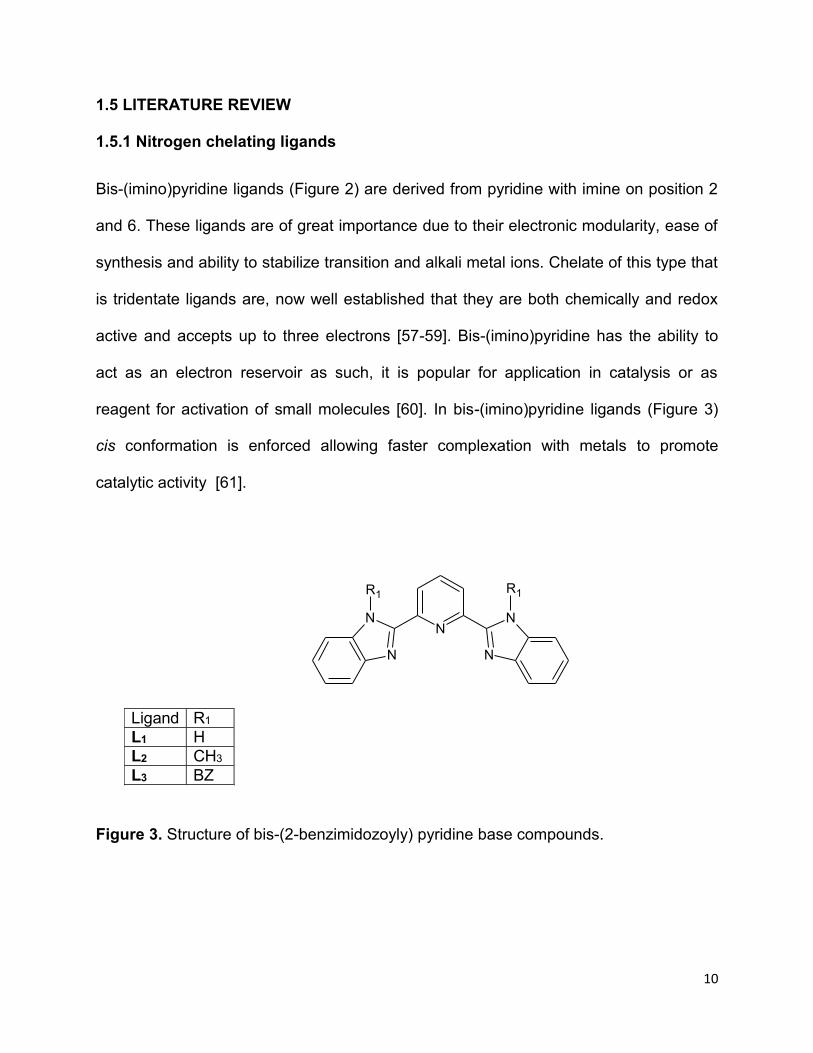
Bis-(imino)pyridine ligands (Figure 2) are derived from pyridine with imine on position 2
and 6. These ligands are of great importance due to their electronic modularity, ease of
synthesis and ability to stabilize transition and alkali metal ions. Chelate of this type that
is tridentate ligands are, now well established that they are both chemically and redox
active and accepts up to three electrons [57-59]. Bis-(imino)pyridine has the ability to
act as an electron reservoir as such, it is popular for application in catalysis or as
reagent for activation of small molecules [60]. In bis-(imino)pyridine ligands (Figure 3)
cis conformation is enforced allowing faster complexation with metals to promote
catalytic activity [61].
Figure 3. Structure of bis-(2-benzimidozoyly) pyridine base compounds.
NN
N N
N
R1R1
Ligand R1
L1 H
L2 CH3
L3 BZ

11
The late transition metals are less oxophilic than the early transition metals, and are
therefore supposed to be more tolerant toward Lewis bases [62, 63]. The late transition
metals combined with tridentate ligands (Figure 4), since the reports of 2,6-bis-
(imino)pyridine new ones have been synthesized that includes complexes with ligands
such as 2,5-bis-(imino)thiophene, 2,5-bis-(imino)-furan, 2,5-bis-(imino)pyrrole, 2,6-bis-
(amine)pyridine, 2,6-bis-(2-benzimidazolyl)pyridine, 2,6-bis-(hydrazone)pyridine, 2,6-
bis-(aryliminophosphoranyl)pyridine and 2,6-bis-(pyrrolyl)pyridine [64].
N
NNN N
R1 R1
RR
R= Ph, Me, H and R 1= Me, H
2,6-bis-(hydrazone)pyridine
N
NNArAr
2,6-bis-(imino)pyridine
N N
N
N
N
R1
RR
R1
2,6-bis-(pyrazolyl)pyridine
R= Ph, Me, H and R 1= Me, H
NN
N N
N
R R
R= Ph, Me and H
2,6-bis(2-benzimidozolyl)pyridine
NP P
N
R
N
R
R1R1
R3
R2
R2 R3 R2
R2
R= Ph, Me, H and R 1= R2= R3= Me, H
2,6-bis-(aryliminophosphoranyl)pyridine
NH NN
ArAr
2,5-bis-(amino)pyrrole
O
N NArAr
2,5-bis-(amino)furan
NN
NR2
R
R
R2 R1= Ph, Me, H and R 2= Me, H
2,5-bis-(amino)pyridine
Figure 4. Structures of some bis-(amino)pyridine ligand

12
Bis-(imino)pyridine is known to be a redox-active ligand, also called redox non-innocent
ligands, and can interact with the metal center to facilitate chemical transformations.
These redox-active ligands can be easily oxidized or reduced due to the energies of
their frontier orbital. The redox non-innocence of the bis-(imino)pyridine ligand (Scheme
1) in the complex which is formulated as an intermediate spin metal center with a doubly
reduced bis-(imino)pyridine dianion [66-69].
R
N
N R
N
Ar- Ar
-Ru
ClCl
+e-
-ClRu
+
Cl
+e-
-Cl
R N R
N
Ar-
N
Ar-
.
Ru+
Ln
R N R
N
Ar-
N
Ar-
. .+nL
Scheme 1. Redox activity of 2,6-bis-(imino)pyridine ligands in Ru coordination
compound (R = Me, Ph)
The stability and catalytic activity of a metal complex depends on the capacity of the
ligand to accept up to three electrons from the metal center through conjugated π-acidic
nitrogen atoms to mitigate the one electron to metal ion [70].
Pyrazolyl base ligand consists of three possible substituting positions on the pyrazole
ring which allows the functionalization of the ligand in order to influence the electronic
and steric properties this will depend on the substituent chosen. Jamson et al,
synthesized and characterized 2,6-bis-(pyrazol)pyridine ligand by combining pyrozolyl
and pyridyl to enable the synthesis of tridentate [65] as shown in Scheme 2.

13
NCl Cl
+ 2NH
N
R3
R2
DMF
1300C
Ligand R2 R3
L4 H H
L5 H Me
L6 Me Me
N N
N
R2
R3
N
N
R2
R3
Scheme 2. Synthesis of Bis-(pyrazolyl)pyridine ligands.
1.5.2 Coordination of metal complexes.
Ruthenium complexes that contains bis-bidentate or tridentate ligands have recently
received considerable attention in molecular electronic devices [71]. Bis-(imino)pyridine
ligands interact with the d orbitals of transition metals through both σ–donor located on
the nitrogen atoms and the π–acceptor conjugated aromatic system [72]. Deng et al.
[73] designed and synthesized a ruthenium complex, RuCl2(PPh3)(Me4BPPy), from the
2,6-bis-(3,5-dimethylpyrazol-1-yl)pyridine (Me4BPPy) in 2-propanol at 80 °C. The
structure was characterized using XRD and showed good crystalline structure.
In 2008, Singh et al. [74] synthesized and characterized ruthenium complexes with
tridentate 2,6-bis-(benzimidazol-2-yl)pyridine ligand. Ruthenium(II) complex was
observed to exhibit strong metal-to-ligand charge transfer (MLCT) band near 475 nm

14
and intra-ligand π-π* transitions appear at 347 and 314 nm at pH 5. The MLCT band
position was found to increase as the pH was increased indicating that the MLCT of 2,6-
bis(benzimidazol-2-yl)pyridine ligand was dependent on pH [74]. These electronic
properties have raised a lot of interest especially in the solar cell industry and in
catalysis.
1.5.3 Application of ruthenium complexes in DSSCs
Ruthenium(II) complexes containing pyridine are the most successful complexes as
dyes in DSSCs. The application of ruthenium complexes (N3 and N719) (Figure 5) was
first reported by Nazeeruddin et al, in 1993 [75].
Ru
N
CSN N
NSCN
N
COOH
COOH
COOH
COOH
Ru
N
SCN
SCN N
N
N
OTBA
COOH
COOH
OTBA
N3 N719
Figure 5. Structure of N3 and N719 Ruthenium complex.

15
Compounds N3 and N719 where N719 are analogous and only differ in their
substituents where N719 contains tetrabutyl ammonium (TBA) in the para position of
pyridines N3 contain two anchoring carboxylic group (-COOH) in the same positions
[76]. Several studies in DSSCs have been carried out using cis-[Ru(dcbH2)2LL’] as dyes.
This is because these complexes contain good anchoring ligand that allow an efficient
absorption onto the surface of the semiconductor, which can be TiO2 or ZnO and their
properties can be enhanced by using different ancillary ligands [77].
In the work reported by Adeloye and Ajibade (2010) the synthesis of ruthenium
complexes with general formula [Ru(L1)(L2)(NCS)2] where L1=4-(9-dianthracenly-10-
(2,3-dimethylacrylic acid)-7-(9-anthracenly-10-(2,3-dimethylacrylic acid)-1,10-
phenthrolline and L2=4,7-bis-(1-methoxyl-1-butane-3-enye)-1,10-phenothrolline utilizing
anthracene derivatives and 1-methoxy-1-butene-3-enyl moiety were introduced to the
Ru(II) complex to increase the π-conjugate to enhance the photophysical properties
(light-harvesting and electronic transfer) [78].
In the work of pyazolypyridine and terpyridine Ru(II) sensitizers Wu et al. (2012)
reported a series novel heteroleptic bis-tridentate Ru(II) sensitizers with
dicarboxyterpyridine and 2,6-bis(5-pyrazolyl)pyridine, the complexes were denoted as
TF 11-14 (Figure 6) Bis-tridentate (terpyridine) sensitizer showed a remarkable
performance in dye sensitized solar cells when compared to a DSSC with N749
(ruthenium polypyridine) sensitizer. The short-circuit photocurrent (Jsc) of TF-12

16
sensitizer found to be 19.0 mA cm−2, an open-circuit voltage (Voc) of 0.71 V, and a fill
factor (FF) of 0.68 and an overall conversion efficiency (η) of 9.21%. The π-conjugated
pendant group was introduced to TF dyes sensitizer to increase both light-harvesting
and photovoltaic energy conversion capability of TF. The carboxyl anchoring group
increased the efficiency Ru(II) sensitizer [79].
N
NRu
N
N
N
N
N
N
N
R
CF3
CF3
HO2C
HO2C
N
NRu
N
N
N
N
N
N
N
CF3
CF3
HO2C
HO2C
R
TF 11, R= 5-(2hexylthiophene)
TF 12, R= 5-(2hexyl-EDOT)
TF 13, R= 5-(2hexylthiophene)
TF 114, R= 5-(2hexyl-EDOT)
Figure 6. Structure of TF 11-14
Recent publications of Lobello et al. (2014) [80] describe the design of a new
ruthenium(II) sensitizer, [Ru(L1)(L2) (NCS)2] where L1 = (4-(5-hexylthiophen-2-yl)-4’(4-
carboxyl-phenyl 2,2’-bipyridine) and L2 = (4,4’-dicarboxy-2,2’-bipyridine), (Figure 7)
based on a dissymmetric bipyridine ligand was synthesized and used in DSCs. The
observed photovoltaic efficiencies were found to be 7.6 %. The binding of bipyridyne

17
ligands occurred through three anchoring carboxylic groups its physical properties are
similar to that of N719 (Figure 5) dye [80].
N
N N
N
S
O
OH
C6H13
Ru
S=C=N N=C=S
N
N
Ru
S=C=N N=C=S
N
O
OH
N
S
C6H13
Figure 7. Structures of [Ru(L1)(L2) (NCS)2] [80]
In work reported of Adeloye et al. [81] a new homoleptic ruthenium(II) complex, with a
general formula [Ru(L1)2(PF6)2], where L1 = bis-4’-(trans-2-methyl-2-butenoic acid)-
terpyridyl was designed. Bis-hexafluorophosphate enhances the stability, photophysical
and redox properties and also increased the length of π-conjugation to enhance MLCT
of the complex, which was found to be far better compared to [Ru(tpy)2]2+. The main
drawback was that the electronic spectra exhibit lower wavelength compared to N3 and
N719 (Figure 5) [81].
1.5.4 Application of cobalt complexes in DSSCs
Large amount of energy can be lost during the regeneration reaction of I-3/I
- system. The
energy is due to corrosiveness of I-3/I- and absorption of light by triiodide [82].

18
Researchers have recently developed new redox compound that have higher redox
potentials than iodide ions [83]. In order to overcome the loss of energy and increase
conversion efficiency of DSSCs, researchers have recently developed a new redox
compounds that hence higher redox potentials that I- ions. Such compounds include
cobalt, iron, copper based complexes [84]. Of these compounds, cobalt (II)/(III)
bipyridine complexes show interesting performance in DSSCs [85]. The use of cobalt
complexes has not been reported to date, these compounds are only employed as
redox mediators for DSSCs.
The absorption of light in the visible region of the solar spectrum in cobalt complexes is
insignificant, and their redox properties can be adapted to use donor/acceptor
substituents on the ligand [86]. For example, cobalt complexes can be used as
alternate of I3−/I− used in dye-sensitized solar cells [87]. In 2001 Nusbaumer et al. [88]
showed that DSSCs containing cobalt complex of 2,6-bis(1-butylbenzimidazol-2-
yl)pyridine (Figure 8), as an electron and redox mediator and had the power conversion
efficiencies at about 5.2 %. The kinetic behavior of cobalt complexes redox mediator
was found to be similar with that of I3−/I− redox couple. These results show that cobalt
complex can be used as mediator and as alternative to commonly use I3−/I−redox couple
used system in DSSC [88].

19
N
N
NN
N
Co
H9C4 C4H9
N
N
N N
N
H9C4C4H9
Figure 8. Cobalt(II) complex of 2,6-bis(1-butylbenzimidazol-2-yl)pyridine.
In another study, Feldt et al. [89] synthesized cobalt complexes of bipyridine and
phenanthroline (Figure 9) These compounds were their redox potential and the
proportionality of the driving force for recombination and the regeneration of dye on
DSSCs. Photovoltaic current was found to be inversely proportion to the redox potential
of cobalt complexes. It was found that the half-life of cobalt tribipyridine complexes was
about 20µs for regeneration of dye on a photovoltaic performance, which was found to
be similar to that of I-3/I- redox couple.

20
N
N
Co
N
N
N
N
R
R
R
CH3
R
CH3
N
N
N
N
Co
N
N
R
R
R
R= H, CH 3, or t-butyl R= H, Cl, NO 2
(a) (b)
Figure 9. Structure of cobalt(II) complexes of (a) bipyridine and (b) phenanthroline.
Cobalt(II/III) tris(5-chloro-1,10-phenanthroline) was found to have a driving force of 390
mV for regeneration of dye which was enough to regenerate more than 80% of the D35
(Figure 10) dye molecules, causing generation of electric current from incident photon to
be above 80%. The only drawback was when cobalt phenanthroline complexes were
used, the photocurrent of the D35 dye sensitized DSCs decreased [89].

21
N
S
O OH
CN
OC4H9
H9C4O
H9C4O
H9C4O
Figure 10. Structure of D35 dye [90]
In the pioneering work of cobalt redox mediators used in DSSCs, Yum et al. designed a
cobalt complex of tridendate ligands [Co(bpypz)2]3/2+(PF6)
3/2 in photovoltaic performance
as redox mediator with Y123 dye (Figure 11) the power conversion efficiency was
found to be over 10% at 100mWcm−2. It was concluded that cobalt redox couple is a
promising alternative to the commonly used I3−/I−redox couple [91].

22
N
S
S
H13C6 C6H13
COOH
CN
OC6H13
H13C6O
H13C6O
H13C6O
Figure 11. Structure of Y123 dye [92]
1.6 Motivation and rationale
Fossil fuels are non-renewable source of energy and their use depletes natural
resources and cause an increase in greenhouse gases such as, carbon monoxide and
carbon dioxide in the atmosphere and consequently global warming [2]. The use of dye
sensitized solar cells as a source of electric energy can provide clean and renewable
energy. Crystalline silicon solar cell being used at present is very expensive and they
require a dopant for them to operate [12]. Such devices are not desirable because of
still possess the disadvantage of high production cost. Recent reports [18] show that
cobalt(II/III) complexes have interesting promising efficiency compared to natural dyes.
Furthermore, ruthenium complexes as dyes can sustain the performance of DSSC for
up to 20 years.

23
1.7 Problem Statement
Researchers are still trying to develop new solar cell technologies that could generate
electric energy at low cost that are competitive with energy generated from fossil fuels
[5]. At present, most of our energy is from fossil fuels, is it possible to get a DSSC as
good as fossil fuel?
Renewable energies such as solar cells have attracted most researchers because it
directly converts solar energy into electric energy without affecting the environment [2].
Can a problem related to depletion of natural resources be resolved by using DSSC as
a source of electrical energy?
Silicon based solar cells have solar energy conversion efficiency of 25% [12]. However,
such devices are associated with high production cost [4]. Is it possible to overcome the
disadvantage of high production cost of silicon solar cells by developing DSSCs with
comparable or better efficiency?
1.8 Aims and objectives
Aim: To synthesize, characterize and evaluate Ru(II) and Co(II) complexes of nitrogen
chelating ligands as sensitizers for DSSCs

24
Objectives:
o To synthesize bis-(imino)pyridine and bis-(pyrazolyl)pyridine based ligands.
o To synthesize ruthenium(II) and Co(II) complexes of these ligands.
o To characterize the ligands, Ru(II) and Co(II) complexes using elemental
analysis and spectroscopic techniques.
o To carry out photophysical and electrochemical studies of the Ru(II) and Co(II)
complexes.
o To fabricate solar cells using the Ru(II) and Co(II) complexes.
o To evaluate the conversion efficiency of the fabricated solar cells.

25
References
[1] Gong, J.; Liang, J.; Sumathy, K. Review on dye-sensitized solar cells (DSSCs):
Fundamental concepts and novel material. Renewable and Sustainable Energy Review,
2012, 16, 5848-5860.
[2] Ludin, N. A.; Mahmoud, A. M. A.; Mohamad, A. B.; Kadhum, A. A. M.; Sopian, K.;
Karim, N. S. A. The review on the development of natural dye photosensitizers for dye
sensitizerd solar cells. Renewable and Sustainable Energy Review, 2014, 31, 386-396.
[3] Ito, S.; Murakami, T. N.; Comte, P.; Liska, P.; Gratzel, C.; Nazeeruddin, M. K.;
Gratzel, M. Fabrication of thin film dye sensitized solar cells with solar to electric power
conversion efficiency over 10%,Thin Solid Films, 2008, 516, 4613-4619.
[4] Ding, J.; Li, Y.; Hu, H.; Bai, L.; Zhang, S.; Yuan, N. The influence of anatase-rutile
mixed phase and ZnO blocking layer on dye-sensitized solar cells based on TiO2
nanofiber photoanodes. Nanoscale Research Letters, 2013, 8, 1-9.
[5] Cheng M. H.; Hsieh, W. F. High-efficiency metal-free organic-dye-sensitized solar
cells with hierarchical ZnO photoelectrode, Energy and Environmental Sciences, 2010,
3, 442-447.
[6] Adeloye, A. O.; Ajibade, P. A.; Cummings, F. R.; Le Roux, L. J.; Mamphweli, S. N.;
Meyer E. L. Synthesis, photophysical and preliminary investigation of the dye-sensitized
solar cells properties of functionalized anthracenyl-based bipyridyl and phenanthrolyl
Ru(II) complexes. Journal of Chemical Sciences, 2013, 125, 17-27.

26
[7] Bajpai, R.; Roy, S.; Koratkar, N.; Misra, D. S. NiO nanoparticles deposited on
graphene platelets as a cost-effective counter electrode in a dye sensitized solar cell,
Carbon, 2013, 5, 56-63.
[8] Odobel, F.; Pellegrin, Y.; Gibson, E. A.; Hagfeldt, A.; Smeigh, A. L.; Hammarstrom,
L. Recent advances and future directions to optimize the performances of p-type dye-
sensitized solar cells. Coordination Chemistry Reviews, 2012, 256, 2414-2423.
[9] Liu, J.; Li, J. Electrochemical analysis of dye adsorption on aligned carbon nanofiber
arrays coated with TiO2 nanoneedles for dye-sensitized solar cell. Frontier of
Optoelectronics in China, 2011, 4, 53-58.
[10] Ashraful, A.; Hironori, A. Molecular design of ruthenium(II) polypyridyl
photosensitizer for efficient nanocrastalline TiO2 solar cells. Journal of Photochemistry
and Photobiology A: Chemistry, 2003, 158, 131-138.
[11] Menzies, D. B.; Cervini, R.; Cheng, Y. B.; Simon, G. P. Nanostructured ZrO2-coated
TiO2 electrodes for dye-sensitised solar cells. Journal of Sol-Gel Sciences and
Technology, 2004, 32, 363-366.
[12] Gratzel, M. Recent advances in sensitized mesoscopic solar cells. Accounts of
Chemical Research, 2009, 42, 1788-1798.
[13] Umar, A. A.; Rahman, M. Y. A.; Taslim, R.; Salleh, M. M. Dye-sensitized solar cell
utilizing quasi one-dimensional of highly compact vertical array ZnO nanorod.
International Journal of Electrochemical Science, 2012, 7, 7253-7260.
[14] Kuang, D.; Ito, S.; Wenger, B.; Klein, C.; Moser, J. E.; Humphry-Baker, R.;
Zakeeruddin, S. M.; Gratzel, M. High molar extinction coefficient heteroleptic ruthenium

27
complexes for thin film dye-sensitized solar cells. Journal of the American Chemistry
Society, 2006, 128, 4146-4154.
[15] Zhang, Q.; Dandeneau, C. S.; Zhou, X.; Cao, G. ZnO nanostructures for dye-
sensitized solar cells. Advanced Materials, 2009, 21, 4087-4108.
[16] Wang, P.; Zakeeruddin, S. M.; Comte, P.; Charvet, R.; Humphry-Baker, R.;
Gratzel, M. Enhance the performance of dye-sensitized solar cells by co-grafting
amphiphilic sensitizer and hexadecylmalonic acid on TiO2 nanocrystal. Journal of
Physical Chemistry B, 2003, 107, 14336-14341.
[17] Lee, K. H.; Suryanarayanan, V.; Ho, K. C; Thomas, K. R. J.; Lin, J. T.; Effects of co-
adsorbate and additive on the performance of dye-sensitized solar cells: A
photophysical study. Solar Energy Materials and Solar Cells, 2007, 91, 1426-1431.
[18] Matthew, S.; Yella, A.; Gao, P.; Humphry-Baker, R.; Curchod, B. F. E.; Ashari-
Astani, N.; Travernelli, I.; Rothlisberger, U.; Nazeeruddin, M. K.; Gratzel, M. Dye
sensitized solar cells with 13% efficiency achieved through the molecular engineering of
porphyrin sensitizers. Nature Chemistry, 2014, 6, 242-247.
[19] Iliopoulos, K.; Guezguez, I.; Kerasidou, A. P.; El-Ghayoury, A.; Branzea, D.; Nita,
G.; Avarvari, N.; Belmabrouk, H.; Couris, S.; Sahraoui,B. Effect of metal cation
complexation on the nonlinear optical response of an electroactive bisiminopyridine
ligand. Dyes and Pigments, 2014, 101, 229-233.
[20] O’Regan, B.; Gratzel, M. A low-cost, high-efficiency solar cell based on dye
sensitized colloidal TiO2 films. Nature, 1991, 353, 737-740.

28
[21] Lu, X., Wei, S.; Wu, C. M. L.; Guo, W.; Zhao, L. Theoretical characterization of
ruthenium complexes containing functionalized bithiophene ligands for dye-sensitized
solar cells. Journal of Organic Chemistry, 2011, 696, 1632-1639.
[22] Bajpai, R.; Roy, S.; Koratkar, N.; Misra, D. S. NiO nanoparticles deposited on
graphene platelets as a cost-effective counter electrode in a dye sensitized solar cell,
Carbon, 2013, 5, 56-63.
[23] Karlsson K. M., Jiang, X.; Eriksson, S. K.; Gabrielsson, E.; Rensom, H.; Hangfeldt,
A. Penoxazine dye for dye-sensitized solar cells: Relationship between molar structure.
Chemistry European Journal, 2011, 17, 6415-6424.
[24] Jamson, D. L.; Goldsby, K. A. 6-bis(N-pyrazolyl)pyridines: The convenient
synthesis of a family of planar tridentate N3 ligands that are terpyridine analogs. Journal
of Organic Chemistry, 1990, 55, 4992-4994.
[25] Ondersma, J. W.; Hamann, T. W. Recombination and redox couples in dye-
sensitized solar cells. Coordination Chemistry Reviews, 2013, 257, 1533-1543.
[26] Buchalska, M.; Kuncewicz, J.; Swietek, E.; Labuz, P.; Baran, T.; Stochel, G.;
Macyk, W. Photoinduced hole injection in semiconductor-coordination compound
systems. Coordination Chemistry Reviews, 2013, 257, 767-775.
[27] Wu, Y.; Zhu, W. Organic dye sensitizers from D-π-A to D-A-π-A: Effects of internal
electron–withdrawing units on molecular absorption, energy level and photovoltaic
performance. Chemical Society Reviews, 2013, 12, 2039-2058.

29
[28]. Zhou, H.; Wu, L.; Gao, Y.; Ma, T. Dye-sensitized solar cells using 20 natural dyes
as sensitizers. Journal of Photochemistry and Photobiology A: Chemistry, 2011, 219,
188-194.
[29]. Pellegrin, Y.; Pleux, L. L.; Blart, L.; Renaud, A.; Chavillon, B.; Szuwarski, N.;
Boujtita, M.; Cario, L.; Jobic, S.; Jacquemin, D.; Odobel, F. Ruthenium polypyridine
complexes as sensitizers in NiO based p-type dye-sensitized solar cells: Effects of the
anchoring groups. Journal Photochemistry and Photobiology A: Chemistry, 2011, 219,
235-242.
[30] Hocevar, M.; Krasovec, U. O.; Berginc, M.; Drazic, G.; Hauptman, N.; Topic, M.
Development of TiO2 pastes modified with Pechini sol-gel method for high efficiency
dye-sensitized solar cell. Journal of Sol-Gel Science Technology, 2008, 48, 156-162.
[31] Peiris, T. A. N.; Alessa; H.; Sagu, J. S.; Bhatti, I. A.; Isherwood, P.; Wijayantha,
K.G.U. Effect of ZnO seed layer thickness on hierarchical ZnO nanorod growth on
flexible substrates for application in dye sensitised solar cells. Journal of Nanoparticle
Research, 2013, 15, 2115-2124.
[32] Gong, H. H.; Hong, S. B.; Hong, S. C. Dispersion controlled platinum/multi-walled
carbon nanotube hybrid for counter electrodes of dye-sensitized solar cells.
Macromolecule Research, 2014, 22, 397-404.
[33] Joshi, P. H.; Korfiatis, D. P.; Potamianou, S. F.; Thoma, K. A. T. Oxide thickness
and roughness factor as parameters for TiO2 dye sensitized solar cells performance.
Russian Journal of Electrochemistry, 2011, 47, 517-521.

30
[34] Lobello, M. G.; Wu, K. L.; Reddy, A. M.; Marotta, G.; Grätzel, M.; Nazeeruddin. M.
K., Chi, Y.; Chandrasekharam, M.; Vitillaro, G.; De Angelis, F. Engineering of Ru(II)
dyes for interfacial and light-harvesting optimization. Dalton Transactions, 2014, 43,
2726-2732.
[35] Moehl, T.; Tsao, N. H.; Wu, K.L.; Hsu, H. C.; Chi, Y. L.; Ronca, E.; De Angelis, F.;
Nazeeruddin, M. K.; Gratzel, M. High open-circuit voltages: Evidence for a sensitizer-
induced TiO2 conduction band shift in Ru(II)-dye sensitized solar cells. Chemistry of
Materials, 2013, 25, 4497−4502.
[36] Ole, A. F.; Santos, G. N. C, Quiroga, R. V. Fabrication and characterization of dye
sensitized solar cells using nanostructured TiO2 photoelectrode. International Journal of
Scientific and Engineering Research, 2012, 8, 1-7.
[37] Mamidi, T.; Mandha, S. B.; Mishra, A. Effects of lithium ions on dye-sensitized ZnO
aggregate solar cells. International Journal of Modern Engineering and Research
Technology, 2012, 2, 3597-3601.
[38] Zhang, X.; Chen, L.; Li, L.; Mao, J.; Wu, W.; Agren, H.; Hua, J. Photovoltaic
properties of bis-(octyloxy)benzo-[c][1,2,5]thiadiazole sensitizers based on N,N-
diphenylthiophen-2-amine donor. Journal of Materials Chemistry, 2014, 2, 4063-4072.
[39] Kim, J. J.; Yoon, J. A new ruthenium containing dipyridylamine ligand for effective
nanocrystalline dye-sensitized solar cells. Inorganic Chimica Acta, 2013, 394, 506-511.
[40] Appleyard, S. Assessing the use of simple dye-sensitized solar cells for drinking
water chrorinarion by communities with limited resources. Renewable Energy, 2009, 34,
1651-1654.

31
[41] Martinez Diaz, M.V.; de la Torre, G.; Torres, T. Lighting porphyrins and
phthalocyanines for molecular photovoltaics. Chemical Communications, 2010, 46,
7090-7108.
[42] Yella, A.; Lee, H. W.; Tsao, W. H. N.; Yi, C.; Chandiran, K. A.; Nazeeruddin, M. D.;
Diau, E. W. G.; Yeh, C. Y.; Zakeeruddin, S. M. Z.; Gratzel, M. Porphyrin-sensitized solar
cells with cobalt (II/III)–based redox electrolyte exceed 12 percent efficiency. Science,
2011, 334, 629-629.
[43] Zhang; C. R.; Liu Z. J.; Chen, Y. H.; Chen H. S.; Wu Y. Z.; Yuan L. H. DFT and
TDDFT study on organic dye sensitizers D5, DST and DSS for solar cells. Journal of
Molecular Structure: Theochem, 2009, 899, 86-93.
[44] Stathatos, E.; Lianos, P. Synthesis of a hemicyanine dye bearing two carboxylic
groups and its use as a photosensitizer in dye-sensitized photoelectrochemical cells.
Chemistry of Materials, 2001, 13, 3888-3892.
[45] Gratzel, M. Conversion of sunlight to electric power by nanocrystalline dye-
sensitized solar cells. Journal of Photochemistry and Photobiology A: Chemistry, 2004,
164, 3-14.
[46] Burdzinski, G.; Karolczak, J.; Ziolek, M. Dynamics of local Stark effect observed for
a complete D149 dye-sensitized solar cell. Physical Chemistry Chemical Physics, 2013,
15, 3889-3896
[47] Ryan, M. PGM Highlights. Progress in ruthenium complexes for dye sensitized
solar cells. Platinum Metals Review, 2009, 53, 216-218.

32
[48] Reynal, A.; Forneli, A.; Palomares, E. Dye structure–charge transfer process
relationship in efficient ruthenium-dye based dye sensitized solar cells. Energy and
Environmental Science, 2010, 3, 805-812.
[49] Wu, W.; Yang, J.; Hua, J.; Tang, J.; Zhang, L.; Long, L.; Tian, H. Efficient and
stable dye-sensitized solar cells based on phenothiazine sensitizers with thiophene
units. Journal of Materials Chemistry, 2010, 20, 1772-1779.
[50] Feldt, S. M.; Gibson, E. A.; Gabrielsson, E.; Sun, L.; Boschloo, G.; Hagfeldt, A.
Design of organic dyes and cobalt polypyridine redox mediators for high-efficiency dye-
sensitized solar cells. Journal of the American Chemical Society, 2010,132, 16714-
16724.
[51] Adeloye, A. O., Ajibade, P. A. A high molar extinction coefficient mono-anthracenyl
bipyridyl heteroleptic ruthenium(II) complex: Synthesis, photophysical and
electrochemical properties. Molecules, 2011, 16, 4615-4631.
[52] Baheti, A.; Singh, P.; Lee, P. C.; Thomas, K. R. J.; Ho, K. C. 2,7-Diaminofluorene-
based organic dyes for dye-sensitized solar cells: Effect of auxiliary donor on optical
and electrochemical properties. Journal of Organic Chemistry, 2011, 76, 4910-4920.
[53] Gratzel, M. Photovoltaic performance and long-term stability of dye-sensitized
meosocopic solar cells. Comptes Rendus Chimie, 2006, 9, 578-583.
[54] Kong, F. T.; Dai, S. Y.; Wang, K. J. Review of recent progress in dye-sensitized
solar cells. Advances in Optoectronics, 2007, 10, 1-13.
[55] Tigreros, A.; Dhas, V.; Ortiz, A.; Insuasty, B.; Martin, N.; Echegoyen, L. Influence
ofacetylene-linked π-spacers ontriphenylamine-fluorene dye sensitized solar cells
performance. Solar Energy Materials and Solar Cells, 2014, 121, 61-68.

33
[56] Bryliakov, K. P.; Talsi, E. P.; Semikolenova, N. V.; Zakharov, V. A. Formation and
nature of the active sites in bis-(imino)pyridine iron-based polymerization catalysts.
Organometallics, 2009, 28, 3225-3232.
[57] Scott, J.; Gambarotta, S.; Korobkov, I.; Budzelaar, P. H. M. Reduction of
(diiminopyridine)iron: Evidence for a non-cationic polymerization pathway.
Organometallics, 2005, 24, 6298-6300.
[58] Sugiyama, H.; Gambarotta, S.; Yap, G. P. A.; Wilson, D. R.; Thiele, S. K. H.
Preparation of an active neodymium catalyst for regioselective butadiene cis-
polymerization supported by a dianionic modification of the 2,6-diiminopyridine ligand.
Organometallics, 2004, 23, 5054-5061.
[59] Campora, J.; Perez, C. M.; Rodrıguez-Delgado, A.; Naz, A. M.; Palma, P.; lvarez,
A. E. Selective alkylation of 2,6-diiminopyridine ligands by dialkylmanganese reagents:
A “one-pot” synthetic methodology. Organometallics, 2007, 26, 1104-1107.
[60] Darmon, J. M.; Turner, R. Z.; Lobkovsky, E.; Chirik P. J. Electronic effects in 4-
substituted bis-(imino)pyridines and the corresponding reduced iron compounds.
Organometallics, 2012, 31, 2275-2285.
[61] Lappalainen, K.; Yliheikkila, K.; Abu-Surrah, A. S.; Polamo, M.; Leskel, M.; Repo, T.
Iron(II)- and cobalt(II) complexes with tridentate bis-(imino)pyridine nitrogen ligands
bearing chiral bulky aliphatic and aromatic substituents: Crystal structure of [CoCl2{2,6-
bis-[R-(bornylimino)methyl]pyridine}]. Zeitschrift fur anorganische und allgemeine
Chemie, 2005, 631, 763-768.
34
[62] Hoogervorst, W. J.; Elsevier, C. J.; Lutz, M.; Spek, A. L. New cis- and trans-
arylplatinum(II) acetylide compounds containing a bis-(imino)aryl [NCN] ligand.
Organometallics, 2001, 20, 4437-4440.
[63] Hoyt, J. M.; Sylvester, K. T.; Semproni, S. P.; Chirik, P. J. Synthesis and electronic
structure of Bis-(imino)pyridine iron metallacyclic intermediates in iron-catalyzed
cyclization reactions. Journal of the American Chemistry Society, 2013, 135, 4862-
4877.
[64] Bouwkamp, M. W.; Lobkovsky, E.; Chirik, P. J. Bis-(imino)pyridine iron(II) alkyl
cations for olefin polymerization. Journal of the American Chemistry Society, 2005, 127,
9660-9661.
[65] Jamson, D. L.; Goldsby, K. A. 6-bis(N-pyrazolyl)pyridines: The convenient
synthesis of a family of planar tridentates N3 ligands that are terpyridine analogs.
Journal of Organic Chemistry, 1990, 55, 4992-4994.
[66] Kaul, F. A. R.; Puchta, G. T.; Schneider, H.; Bielert, F.; Mihalios, D.; Herrman, W.
A.Immobilization of bis-(imino)pyridyliron(II) complexes on silica. Organometallics, 2002,
21, 74-82.
[67]. Gong, D.; Jia, X.; Wang, B.; Zhang, X.; Jiang, L. Synthesis, characterization, and
butadiene polymerization of iron(III),iron(II) and cobalt(II) chlorides bearing 2,6-bis-(2-
benzimidazolyl)pyridylor 2,6-bis-(pyrazol)pyridine ligand. Journal of Organometallic
Chemistry, 2012, 702, 10-18.
[68] Hoogervorst, W. J.; Goubitz, K.; Fraanje, J.; Lutz, M.; Spek, A. L.; Ernsting, J. M.;
Elsevier, C. J. Bis-(imino)aryl)rhodium(III) halide and methyl compounds.
Organometallics, 2004, 23, 4550-4563.

35
[69] Bianchini. C.; Lee, H. M. Cyclopropanation of styrene with ethyl diazoacetate
catalyzed by chiral and achiral ruthenium 2,6-bis-(imino)pyridyl complexes
Organometallics, 2000, 19, 1833-1840.
[70] Darmon, J. M.; Stieber, S. C. E.; Sylvester, K. T.; Fernandez, I.; Lobkovsky, E.;
Semproni, S. P.; Bill, E.; Wieghardt, K.; DeBeer, S.; Chirik, P. J. Oxidation of carbon-
carbon bonds with a redox-active bis-(imino)pyridine iron complex. Journal of the
American Chemistry Society, 2012, 134, 17125-17137.
[71] Chetia, B.; Iyer P. K. 2,6-Bis-(2-benzimidazolyl)pyridine as a chemosensor for
fluoride ions. Tetrahedron Letters, 2008, 49, 94-97.
[72] Chetia, B.; Iyer, P. K. Utilization of 2,6-bis-(2-benzimidazolyl)pyridine to detect toxic
benzene metabolites. Tetrahedron Letters, 2007, 48, 47-50.
[73] Deng, H.; Yu, Z.; Dong, J.; Wu, S. 2,6-Bis(3,5-dimethylpyrazol-1-yl)pyridine: A
useful pseudo-N3 ligand in efficient ruthenium(II)-catalyzed transfer hydrogenation of
ketones , Organometallics, 2005, 24, 4110-4112.
[74] Singh, A.; Chetia, B.; Mobin, S. M.; Das, G.; Iyer, P. K.; Mondal, B. Ruthenium
monoterpyridine complexes with 2,6-bis-(benzimidazol-2-yl)pyridine: Synthesis, spectral
properties and structure. Polyhedron, 2008, 27, 1983-1988.
[75] Nazeeruddin, M. K.; Kay, A.; Rodicio, I.; Humphry-Baker, R.; Muller, E.; Liska, P.;
Vlachopoulos, N.; Gratzel, M. Converversion of light to electicity by cis-X2bis(2,2’-
bipyridyl-4,4’-dicarboxylate)ruthenium(II) charge-transfer sensitizers (X= Cl-, Br-, I-, CN-
and SCN-) on nanocrystalline titanium dioxide electrodes. Journal of the American
Society, 1993, 115, 6382-6390.

36
[76]. Lee, H. J.; Chen, P.; Moon, S. J.; Sauvage, F.; Sivula, K.; Bessho, T.; Gamelin, D.
R.; Comte, P.; Zakeeruddin, S. M.; Seok, S.; Gratzel, M.; Nazeeruddin, M. K. CdSe
quantum dot (QD) and molecular dye hybrid sensitizers for TiO2 mesoporous solar cells:
working together with a common hole carrier of cobalt complexes. Chemical
Communications, 2010, 46, 8788-8790.
[77] Andre, S. P.; Melina, K. I.; Yukie, M. I. N. Metal complex sensitizers in dye
sensitized solar cells. Coordination Chemistry Reviews, 2004, 48, 1343-1361.
[78] Adeloye, A. O.; Ajibade, P. A. Synthesis and characterization of a Ru(II) complex
with functionalized phenanthroline ligands having single-double linked anthracenyl and
1-methoxy-1-buten-3-yne moieties. Molecules, 2010, 15, 7570-7581.
[79] Wu, K. L.; Li, C. H.; Chi, Y.; Clifford, J. N.; Cabau, L.; Palomares, E.; Cheng, Y. M.;
Pan, H. A.; Chou, T. P. Dye molecular structure device open-circuit voltage correlation
in Ru(II) sensitizers with heteroleptic tridentate chelates for dye-sensitized solar cells.
Journal of the American Chemical Society, 2012, 134, 7488-7496.
[80] Lobello, M. G.; Wu, K. L.; Reddy, A.M.; Marotta, G.; Gratzel, M.; Nazeeruddin, M.
K.; Chi, Y.; Chandrasekharam, M.; Vitillaro, G.; De Angelis, F. Engineering of Ru(II)
dyes for interfacial and light-harvesting optimization. Dalton Transactions, 2014, 43,
2726-2732.
[81] Adeloye, A. O.; Olomola, T. O.; Adebayo, A. I.; Ajibade, P. A. A high molar
extinction coefficient bisterpyridyl homoleptic Ru(II) complex with trans-2-methyl-2-
butenoic acid functionality: Potential dye for dye-sensitized solar cells, International
Journal of Molecular Science, 2012, 13, 3511-3526.

37
[82] Yum, J. H.; Baranoff, E.; Kessler, F.; Moehl, T.; Ahmad, S.; Bessho, T.; Marchioro,
A.; Ghadiri, E.; Moser, E. J. E.; Yi, C.; Nazeeruddin, M. K.; Gratzel, M. A cobalt
complex redox shuttle for dye-sensitized solar cells with high open-circuit potentials.
Nature, 2001, 414, 338-344.
[83] Kim, H. S.; Lee, C. R.; Im, J. H.; Lee, K. B.; Moehl, T.; Marchioro, A.; Moon, S. J.;
Humphry-Baker, R.; Yum, J. H.; Moser, J. E.; Gratzel, M.; Park, N. Lead iodide
perovskite sensitized all-solid-state submicron thin film mesoscopic solar cell with
efficiency exceeding 9%. Scientific Reports, 2012, 2, 591-597.
[84] Nusbaumer, H.; Zakeeruddin, S. M.; Moser, J. E.; Gratzel, M. An alternative
efficient redox couple for the dye-sensitized solar cells system. European Journal of
Chemistry, 2003, 9, 3756-3763.
[85] Lee, H. J.; Chen, P.; Moon, S. J.; Sauvage, F.; Sivula, K.; Bessho, T.; Gamelin, D.
R.; Comte, P.; Zakeeruddin, S. M.; Seok, S.; Nazeeruddin, M. K.; Gratzel, M.
Regenerative PbS and CdS quantum dot sensitized solar cells with a cobalt complex as
hole mediator. Langmuir, 2009, 25, 7602-7608.
[86] Klahr, B. M.; Hamann, T. W. Performance enhancement and limitations of cobalt
bipyridyl redox shuttles in dye-sensitized solar cells. Journal of Physical Chemistry C,
2009, 113, 14040-14045.
[87] Nelson, J. J.; Amick, T. J.; Elliott, M. C. Mass transport of polypyridyl cobalt
complexes in dye-sensitized solar cells with mesoporous TiO2 photoanodes. Journal of
Physical Chemistry C, 2008, 112, 18255-18263.
[88] Nusbaumer, H.; Moser, J. E.; Zakeeruddin S. M.; Nazeeruddin, M. K.; Gratzel, M.

38
Co(dbbip)22+ complex rivals tri-iodide/Iodide redox mediator in dye-sensitized
photovoltaic cells. Journal of Physical Chemistry B, 2001, 105, 10461-10464.
[89] Feldt, S. M.; Wang, G.; Boschloo, G.; Hagfeldt, A. Effects of driving forces for
recombination and regeneration on the photovoltaic performance of dye-sensitized solar
cells using cobalt polypyridine redox couples. Journal of Physical Chemistry C, 2011,
115, 21500-21507.
[90] Pollander, L. E.; Yella, A.; Curchod, B. F. E.; Ashari Asani, N.; Teuscher, J.;
Scopelliti, R.; Gao, P.; Mathew, S.; Moser, J. S.; Tavernelli, I.; Rothlisberger, U.;
Gratzel, M.; Nazeeruddin, M. K.; Frey. J. Towards compatibility between ruthenium
sensitizers and cobalt electrolytes in dye-sensitized solar cells. Angewandte Chemie,
2013, 52, 8731-8735.
[91] Yum, J. H.; Baranoff, E.; Kessler, F.; Moehl, T.; Ahmad, S.; Bessho, T.; Marchioro,
A.; Ghadiri, E.; Moser, J. E.; Yi, C.; Nazeeruddin, M. K.; Gratzel, M. A cobalt complex
redox shuttle for dye-sensitized solar cells with high open-circuit potentials. Nature
Communications, 2012, 631, 1655-1662
[92] Clifford, J. N.; Planell, M.; Palomares, E. Advances in high efficiency dye sensitized
solar cells based on Ru(II) free sensitizers and a liquid redox electrolyte. Journal of
Materials Chemistry, 2012, 22, 24195-24201.

39
CHAPTER 2
2.0 EXPERIMENTAL
2.1 Chemicals and solvents
RuCl3 3H2O, CoCl2 6H2O, 1,2-phenylenediamine, polyphosphoric acid, pyridine-2,6-
carboxylic acid, ammonium solution, pyrazole, 2,5-dimethylpyrazol, sodium hydrate,
2,6-dichloropyridine-4-carboxylic acid, MgSO4, potassium hydroxide, potassium
thiocynate, DMF, DMSO, acetone, ethanol, bromobezene, chlorobut-2-ane, THF,
dichloromethane and diethyl ether, all the chemicals were bought from Sigma Aldrich.
2.2 Characterization techniques
2.2.1 FTIR spectroscopy
The FTIR spectra of different nitrogen chelating ligands and complexes (as KBr pellets)
were obtained by using Perkin-Elmer Paragon 2000 spectrophotometer at 370 cm-1 to
4400 cm-1 range.
2.2.2 UV-Vis spectroscopy
Uv-Vis spectra of ligands and complexes were recorded on a 1 cm path length quartz
cell on a Perkin-Elmer Lambda 25 UV-Vis spectrophotometer using DMSO as a solvent.

40
2.2.3 NMR spectroscopy
1H NMR and 13C NMR spectra were recorded on a Buker EMX 400 MHz
spectrophometer.
2.2.4 Melting point
The melting point of the compounds was determined using Stuart melting point
apparatus.
2.2.5 Electrochemistry
Cyclic voltammetry measurements were obtained using Autolab potentiostat with three
electrodes, glassy carbon working electrode, Ag/AgCl reference electrode and Pt
counter electrode. The potential range was +1.5 to -1.5 at a scan rate of 100 mVs-1
. The
three electrode were immersed in 0.5 mM of cobalt(II) and ruthenium(II) solution in
water with 0.1 M of phosphate buffer solution (PBS) as a supporting electrolyte.
Bubbling nitrogen gas purged through the solution for 15 minutes to remove interfering
oxygen gas during the measurements deoxygenated the solutions. After each
measurement, the working electrode was cleaned with alumina and water on a felt pad
and rinsed with water.
2.2.6 Solar cell fabrication
Scotch tape was put on the conducting side of Indium Tin Oxide (ITO), TiO2 paste and
flattens it with a razor blade on the same side of the ITO glass. The electrode was put

41
on top of a hot plate and heated at 450 °C for 30 minutes. The concentration of the dye
solution was 0.3 mM. TiO2 electrode was dipped into the dye solution for 10 minutes. Pt
plate electrode with a hole was put on top of a hot plate at 450 °C for 10 minutes to
activate the electrode. The TiO2/dye electrode was taken out from the dye solution and
washed with fresh ethanol and allowed to dry. The two electrodes were combined and a
sealer was placed between the two electrodes and clipped with a blinder then heated at
70 °C for 15 minutes. After cooling, electrode construct was filled with electrolyte and
the hole was sealed with a cap sealer. A solar analyzer was used to characterize the
cells.
2.3 Preparation of nitrogen chelating ligands
2.3.1 Preparation of 2,6-bis(2-benzimidazolyl)pyridine (L1).
NHOOC COOH
+NH2
NH2
N
N
NH
NH
N
PPA
1400C
2
Scheme 3. Synthesis of 2,6-bis(2-benzimidazolyl)pyridine.
The ligand 2,6-bis(2-benzimidazolyl)pyridine (L1) was synthesized according to Singh
and co-workers procedure [1]. Under nitrogen, pyridine-2,6-dicarboxylic acid (1.7 g, 13
mmol) and 1,2-phenylenediamine (2.13 g, 26.4 mmol) were added to 3.9 g of
polyphosphoric acid. The mixture was refluxed while stirring at 150 °C for 6 h. The

42
mixture was cooled to 90°C and poured into 50 mL of water. Subsequently, the mixture
was neutralized to pH 8 with ammonium solution. The resultant white solid was
collected by filtration and repeatedly washed with methanol. The equation of the
reaction is as shown in Scheme 3. Yield: 3.23g, 79%, m.p. 180°C, IR (KBr pellet) (cm-
1): 3208, 3105, 2822, 2364, 2208, 1945, 1716,1675,1725, 1517,1462, 1206, 1067, 896,
533.
2.3.2 Preparation of 2,6-bis(1-but-2-ylbenzimidazol-2-yl)pyridine (L2).
N
N
NH
NH
N
+ 2 C4H9Cl KOH
AcetoneN
N
NN
N
C4H9 C4H9
Scheme 4. Synthesis of 2,6-bis(but-2-ylbenzimidazol-2-yl)pyridine.
The synthesis of 2,6-bis(1-but-2-ylbenzimidazol-2-yl)pyridine (L2) (Figure 4) was done
using the synthetic route reported by Gong and co-workers [2]. The alkylation of L1 was
done as shown in Scheme 4. 2-chlorobutane (1.2 g, 7.71 mmol), 2,6-bis-(2-
benzimidazolyl)pyridine (L1) (1.2 g, 3.85 mmol) and KOH (0.28 g, 4.98 mmol) were
dissolved in 30 mL of acetone and refluxed for 4 h at 35°C. After cooling an equal
amount was added to the mixture, which was extracted by dichloromethane, the organic
layer was dried over MgSO4 and evaporated to dryness [2]. Yield 1.11g, 68%, m.p.
180°C, IR (KBr pellet) (cm-1): 3235, 2370, 2270, 2201, 1937, 1622, 1460, 1091, 791,
618.
43
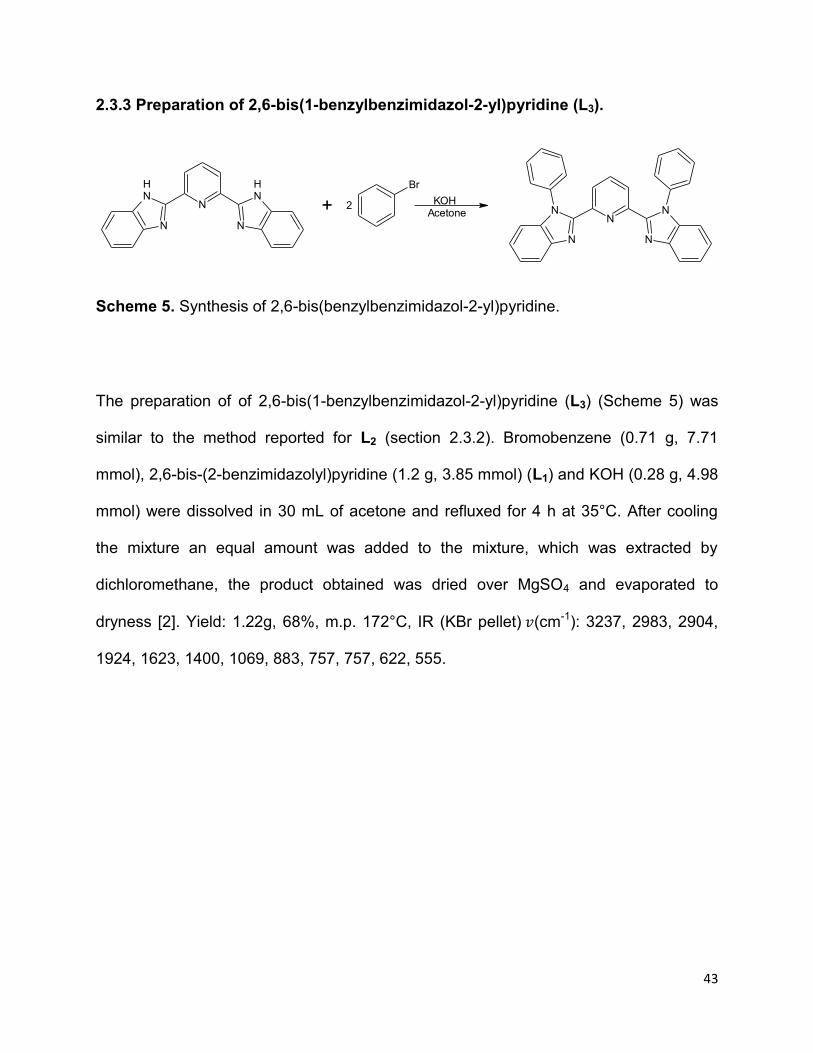
2.3.3 Preparation of 2,6-bis(1-benzylbenzimidazol-2-yl)pyridine (L3).
N
N
NH
NH
N
+ 2 KOHAcetone
N
N
NN
N
Br
Scheme 5. Synthesis of 2,6-bis(benzylbenzimidazol-2-yl)pyridine.
The preparation of of 2,6-bis(1-benzylbenzimidazol-2-yl)pyridine (L3) (Scheme 5) was
similar to the method reported for L2 (section 2.3.2). Bromobenzene (0.71 g, 7.71
mmol), 2,6-bis-(2-benzimidazolyl)pyridine (1.2 g, 3.85 mmol) (L1) and KOH (0.28 g, 4.98
mmol) were dissolved in 30 mL of acetone and refluxed for 4 h at 35°C. After cooling
the mixture an equal amount was added to the mixture, which was extracted by
dichloromethane, the product obtained was dried over MgSO4 and evaporated to
dryness [2]. Yield: 1.22g, 68%, m.p. 172°C, IR (KBr pellet) (cm-1): 3237, 2983, 2904,
1924, 1623, 1400, 1069, 883, 757, 757, 622, 555.

44
2.3.4 Preparation of 2,6-bis(pyrazol)pyridine (L4)
N
+ 2
NH
N
H
H
DMF
130oC
N N
N
N
N
H
HH
H
Scheme 6. Preparation of 2,6-bis(pyrazol)pyridine (L4)
The method used for synthesis 2,6-bis(pyrazol)pyridine (L4) was adopted from Abbo
and Titinchi’s procedure [3]. Pyrazole (1.2 g, 17.6 mmol) was placed in DMF 30 mL in a
100mL round bottom flask, sodium hydrate (0.422 g, 17.6 mmol) was added to the
mixture. The mixture was stirred under nitrogen at 50 °C for 20 minutes. 2,6-
dichloropyridine-4-carboxylic acid (1.39 g, 5.86 mmol) was added and refluxed for 24 h
at 130°C. The reaction was carried out as presented in (Scheme 6). After cooling the
mixture 25 mL of water was added which was extracted with dichloromethane. The
organic layer was dried over MgSO4 and evaporated to dryness [3]. Yield: 0.91g, 73 %,
m.p. 80°C, IR (KBr pellet) (cm-1): 3365, 2976, 2394, 2364,1994, 1664, 1395, 1253,
1043, 831,763, 613.

45
2.3.5 Preparation of 2,6-bis(3,5-dimethylpyrazol)pyridine (L5).
N
+ 2
NH
N
CH3
CH3
DMF
130oC
N N
N
N
N
CH3
CH3CH3
CH3
Scheme 7. Synthesis of 2,6-bis(3,5-dimethylpyrazolyl)pyridine.
2,6-bis(3,5-dimethylpyrazol)pyridine, L5 (Scheme 7) was prepared in a similar method
used for L4 (section 2.3.4). 3,5-dimethypyrazole (1.3 g, 13.5 mmol) was placed in DMF
30 mL in a 100 mL round bottom flask, sodium hydrate (0.33 g, 13.5 mmol) was added
to the mixture. The reaction was carried out under nitrogen at 50 °C for 20 minutes, 2,6-
dichloropyridine-4-carboxylic acid (1.07 g, 4.5 mmol) was added and refluxed for 24 h at
130 °C. After cooling the mixture 25mL of water was added to the mixture that was
extracted with dichloromethane. The product was dried over MgSO4 and evaporated to
dryness [3]. Yield: 0.83g, 69%, m.p. 82°C, IR (KBr pellet) (cm-1): 3410, 3198, 2903,
2552, 2366, 1608, 1306, 1161, 1090, 841, 714, 621, 437.
2.4 Preparation of Ruthenium (II) precursor [RuCl2(DMSO)4 ].
RuCl3DMSO
Reflux, 5 min[RuCl2(DMSO) 4]
.3H2O ...................................8
The ruthenium precursor was prepared using Bianchi’s method [4]. RuCl3 3H2O (1g, 1.9
mmol) of was refluxed at 130 °C in DMSO 8 mL for 20 minutes in air. The reaction is as

46
shown in equation 8. The solution changed from dark to light yellow and bright yellow
precipitate was formed during cooling then 30 mL acetone was added and a yellow
precipitate was filtered off washed three times with times with acetone.
2.5 Synthesis of ruthenium(II) complexes.
2.5.1 Synthesis of [RuL1L0(NCS)2] (C1)
+ RuCl2(DMSO) 4 +NHOOC COOH
2 KSCN DMF
(L1) (L0)
N
NH
NH
NH
NH
N
COOH
HOOC
N
N
NH
NH
N
Ru
NCS
NCS
2KCl+
(C1)
Scheme 8. Synthesis of [RuL1L0(NCS)2]

47
The method used to synthesize C1 (Scheme 8) was adopted from Adeloye and Ajibade
procedure [5]. Under nitrogen, 2,6-bis-(2-benzimidazolyl)pyridine (L1) (0.12 g, 0.206
mmol) and [RuCl2(DMSO)4] (0.2 g, 0.206 mmol) were dissolved in 25 mL of DMF. The
mixture was refluxed in the dark for 4 h, pyridine-2,6-dicarboxylic acid (0.069 g, 0.206
mmol) was added to the mixture and refluxed for 2 h. After 2h excess potassium
thiocynate was added to the mixture and refluxed for 8 h. The reaction mixture was
cooled at room temperature, the DMF was evaporated under vacuum. The residue was
suspended in diethyl ether, the brown solid was filtered under vacuum, rinsed with
diethyl ether and dried under vacuum [5]. Yield: 89 mg, 62%, m.p. 220°C, IR (KBr
pellet) (cm-1): 3409, 3244, 2839, 2374, 2122, 2084, 1620, 1464, 1400, 1397, 1308,
1109, 1068, 818, 622.

48
2.5.2 Synthesis of [RuL2L0(NCS)2] (C2).
+ RuCl2(DMSO) 4 +NHOOC COOH
2 KSCN DMF
(L0)
N
NH
NN
NH
H9C4 C4H9
N
COOH
HOOC
N
N
NN
N
Ru
NCS
NCS
C4H9H9C4
(L2)
+ 2KCl
(C2)
Scheme 9. Synthesis of [RuL2L0(NCS)2]
The synthesis of C2 (Scheme 9) was carried out in a similar method used for C1 (section
2.5.1). 2,6-bis-(butylbenzimidazolyl)pyridine (0.175 g, 0.206 mmol) and [RuCl2(DMSO)4]
(0.2 g, 0.206 mmol) were placed in 25 mL of DMF. The mixture was refluxed under
nitrogen in the dark, after 4 h pyridine-2,6-dicarboxylic acid (0.069 g, 0.206 mmol) was
added to the mixture then excess potassium thiocynate was added after 2 h. The
mixture was refluxed for 8 h, after cooling down the reaction medium at room
temperature, the DMF was evaporated under vacuum. The product was suspended in
diethyl ether, the brown solid was filtered under vacuum, rinsed with diethyl ether and
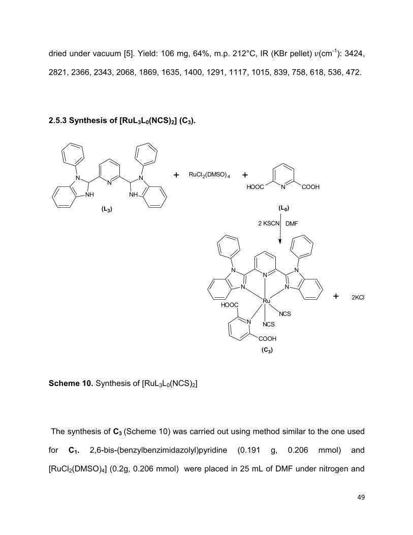
49
dried under vacuum [5]. Yield: 106 mg, 64%, m.p. 212°C, IR (KBr pellet) (cm-1): 3424,
2821, 2366, 2343, 2068, 1869, 1635, 1400, 1291, 1117, 1015, 839, 758, 618, 536, 472.
2.5.3 Synthesis of [RuL3L0(NCS)2] (C3).
N
NH
NN
NH
+ RuCl2(DMSO) 4 +NHOOC COOH
N
COOH
HOOC
N
N
NN
N
Ru
NCS
NCS
2 KSCN DMF
(L3) (L0)
+ 2KCl
(C3)
Scheme 10. Synthesis of [RuL3L0(NCS)2]
The synthesis of C3 (Scheme 10) was carried out using method similar to the one used
for C1. 2,6-bis-(benzylbenzimidazolyl)pyridine (0.191 g, 0.206 mmol) and
[RuCl2(DMSO)4] (0.2g, 0.206 mmol) were placed in 25 mL of DMF under nitrogen and

50
refluxed for 4 h. Pyridine-2,6-dicarboxylic acid (0.069 g, 0.206 mmol) was added to the
mixture, after 2 h excess potassium thiocynate was added and refluxed for 8 h. The
reaction mixture was allowed to cool at room temperature, the solvent was removed
under vacuum. The residue was precipitated in diethyl ether, the final product was
filtered under vacuum, rinsed with diethyl ether and dried under vacuum. Yield: 47 mg,
27%, m.p. 210°C, IR (KBr pellet) (cm-1): 3429, 2955, 2819, 2359, 2124, 2067, 1978,
1646, 1510, 1377, 1116, 1019, 618, 538.
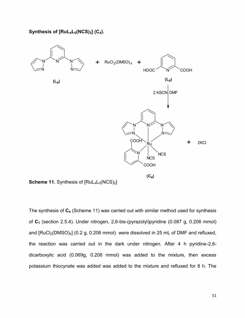
51
Synthesis of [RuL4L0(NCS)2] (C4).
Scheme 11. Synthesis of [RuL4L0(NCS)2]
The synthesis of C4 (Scheme 11) was carried out with similar method used for synthesis
of C1 (section 2.5.4). Under nitrogen, 2,6-bis-(pyrazolyl)pyridine (0.087 g, 0.206 mmol)
and [RuCl2(DMSO)4] (0.2 g, 0.206 mmol) were dissolved in 25 mL of DMF and refluxed,
the reaction was carried out in the dark under nitrogen. After 4 h pyridine-2,6-
dicarboxylic acid (0.069g, 0.206 mmol) was added to the mixture, then excess
potassium thiocynate was added was added to the mixture and refluxed for 8 h. The
N N
N
N
N
+NHOOC COOH
RuCl2(DMSO) 4 +
(L4)(L0)
DMF2 KSCN
N
COOH
COOH
N N
N
N
N
Ru
NCSNCS
2KCl
(C4)
+

52
reaction mixture was cooled at room temperature, the DMF was evaporated under
vacuum. The product was filtered after precipitation with diethyl ether.
Yield: 63.8 mg, 52%, m.p. 235°C, IR (KBr pellet) (cm-1): 3417, 2971, 2971, 2949, 2842,
2368, 2126, 2067, 1869, 1638, 1454, 1397, 1112, 1055, 1016, 619, 477.

53
2.5.5 Synthesis of [RuL5L0(NCS)2] (C5).
Scheme 12. Synthesis of [RuL5L0(NCS)2]
The complex, C5 was prepared using similar method for the synthesis of C1 (section
2.5.1). 2,6-bis-(3,5-dimethylzolyl)pyridine (0.11 g, 0.206 mmol) and [RuCl2(DMSO)4] (0.2
g, 0.206 mmol) were added and the mixture was refluxed in 25 mL DMF for 4h.
Pyridine-2,6-dicarboxylic acid (0.069 g, 0.206 mmol) was added to the reaction mixture
then after 2 h excess potassium thiocynate was added and refluxed for 8 h. The
equation for synthesis of C5 is shown in Scheme 12. The mixture was cooled at room
N N
N
N
N
CH3
CH3 CH3
CH3
+NHOOC COOH
RuCl2(DMSO) 4 +
(L5)(L0)
DMF2 KSCN
N
COOH
COOH
N N
N
N
N
Ru
NCSNCS
CH3
CH3
CH3
CH3 2KCl
(C5)
+

54
temperature and DMF was evaporated under vacuum. The product was precipitated
with diethyl ether, the brown solid finally was filtered and dried under vacuum. Yield:
57.7mg, 43%, m.p. 230°C, IR (KBr pellet) (cm-1): 3424, 2949, 2839, 2365, 2069, 1870,
1646, 1454, 1398, 1113, 1054, 1020, 619, 539.
2.6 Synthesis of cobalt(II) complexes
2.6.1 Synthesis of [CoL1L0(NCS)2] (C6).
+ CoCl2 +NHOOC COOH
2 KSCN EtOH
(L0)(L1)
+ 2KCl
(C6)
.6H2O
N
N
NH
NH
N
N
COOH
HOOC
N
N
NH
NH
N
Co
NCS
NCS
Scheme 13. Synthesis of [CoL1L0(NCS)2]
55
[CoCl2 6H2O] (0.2 g, 0.841 mmol) and 2,6-bis-(benzimidazolyl)pyridine (0.262 g, 0.841
mmol) were dissolved in a minimal amount of ethanol. The solution was left to stir at
reflux for 3 h. After 3 h pyridine-2,6-dicarboxylic acid (0.140 g, 0.841 mmol) was added
to the mixture then excess potassium thiocynate (0.327 g, 3.364 mmol) was added after
2 h. The mixture was refluxed for 4 h, after cooling down the reaction medium at room
temperature, ethanol was evaporated under vacuum diethyl ether was added to the
solution to precipitate the compound. The product was then filtered and washed with,
ethanol, and diethyl ether; dried under vacuum [6]. Yield: 0.4g, 74%, m.p. 240°C, IR
(KBr pellet) (cm-1): 3415, 3235, 2839, 2374, 2122, 2067, 1634, 1464, 1398, 1308,
1115, 1058, 1017, 618, 540, 473.

56
2.6.2 Synthesis of [CoL2L0(NCS)2] (C7).
+ CoCl2 +NHOOC COOH
2 KSCN EtOH
(L0)(L2)
+ 2KCl
(C7)
.6H2O
N
NH
NN
NH
C4H9H9C4
N
COOH
HOOC
N
N
NN
N
Co
NCS
NCS
C4H9H9C4
Scheme 14. Synthesis of [CoL2L0(NCS)2]
The complex, C7 was prepared in a similar method as reported for C6 (section 2.6.1)
[CoCl2 6H2O] (0.2 g, 0.841 mmol) and 2,6-bis-(2-butylmidazolyl)pyridine (0.356 g, 0.841
mmol) were dissolved and refluxed for 3 h. After 3 h pyridine-2,6-dicarboxylic acid
(0.140 g, 0.841 mmol) was added and refluxed for 2 h. Excess potassium thiocynate
(0.327 g, 3.364 mmol) was added to and reaction mixture and was also added and
refluxed for 4 h. The equation for the reaction is as shown in Scheme 14. After cooling

57
down the reaction medium at room temperature, ethanol removed by rotatory
evaporator, diethyl ether was added to the solution to precipitate the compound. The
product obtained was filtered, washed with ethanol then diethyl ether and dried under
vacuum [6]. Yield: 0.46g, 72%, m.p. 242°C, IR (KBr pellet) (cm-1): 3418, 2839, 2374,
2170, 2068, 1869, 1623, 1427, 1304, 1291, 1102, 1015, 839, 750, 618, 536, 422.
2.6.3 Synthesis of [CoL3L0(NCS)2] (C8).
+ CoCl2 +NHOOC COOH
2 KSCN EtOH
(L0)
N
NH
NN
NH
N
COOH
HOOC
N
N
NN
N
Co
NCS
NCS
(L3)
+ 2KCl
(C8)
.6H2O
Scheme 15. Synthesis of [CoL3L0(NCS)2]

58
The synthesis of C8 (Scheme 15) was carried out using similar method reported for C6
(section 2.6.1). [CoCl2 6H2O] (0.2 g, 0.841 mmol) and 2,6-bis-(2-
buytlbenzimidazolyl)pyridine (0.389 g, 0.841 mmol) were added and refluxed for 3 h.
Pyridine-2,6-dicarboxylic acid (0.140 g, 0.841 mmol) was added to the mixture and
refluxed for 2h then excess potassium thiocynate (0.327 g, 3.364 mmol) was added and
refluxed for 4h. The reaction was allowed to cool at room temperature then ethanol was
evaporated under vacuum. The product obtained after precipitation with diethyl ether
was filtered and washed with, ethanol, and diethyl ether; dried under vacuum [6]. Yield:
0.42g, 62%, m.p. 240°C, IR (KBr pellet) (cm-1): 3415, 3235, 2496, 2368, 1622, 1394,
1283, 1075, 917, 776, 733, 619, 541.

59
2.6.4 Synthesis of [CoL4L0(NCS)2] (C9).
N N
N
N
N
+NHOOC COOH
CoCl2 +
(L4)(L0)
EtOH2 KSCN
N
COOH
COOH
N N
N
N
N
Co
NCSNCS
.
.6H2O
2KCl+
(C9)
Scheme 16. Synthesis of [CoL4L0(NCS)2]
The synthesis of C9 (Scheme 16) was carried using similar method used for C6 (section
2.6.1). [CoCl2 6H2O] (0.2 g, 0.841 mmol) and 2,6-bis-(pyrazolyl)pyridine (0.178 g, 0.841
mmol) were dissolved and refluxed. After 3 h pyridine-2,6-dicarboxylic acid (0.140 g,
0.841 mmol) was added to the mixture and refluxed for 2h. Excess potassium
thiocynate (0.327 g, 3.364 mmol) was added and refluxed for 4 h. The reaction mixture
was cooled and methanol was removed under vacuum. The obtained after precipitation
with diethyl ether was filtered and dried [6]. Yield: 0.27g, 58%, m.p. 250°C, IR (KBr

60
pellet) (cm-1): 3409, 3244, 2340, 2043, 1624, 1447, 1396, 1109, 984, 838, 737, 622,
455.
2.6.5 Synthesis of [CoL5L0(NCS)2] (C10).
N N
N
N
N
CH3
CH3
CH3
CH3
+NHOOC COOH
CoCl2 +
(L5)(L0)
EtOH2 KSCN
N
COOH
COOH
N N
N
N
N
Co
NCSNCS
CH3
CH3
CH3
CH3
.
.6H2O
2KCl+
(C10)
Scheme 17. Synthesis of [CoL5L0(NCS)2]
The synthesis of C10 (Scheme 17) was prepared in a similar method reported for C6
(section 2.6.1). [CoCl2 6H2O] (0.2 g, 0.841 mmol) and 2,6-bis-(benzimidazolyl)pyridine
(0.225 g, 0.841 mmol) were dissolved in a minimal amount of ethanol and refluxed for
3h. Then pyridine-2,6-dicarboxylic acid (0.140 g, 0.841 mmol) was added to the mixture
then excess potassium thiocynate (0.327 g, 3.364 mmol) was added after 2 h. The

61
mixture was refluxed for 4 h, after cooling down the reaction mixture at room
temperature. Ethanol was evaporated under vacuum, the obtained product after
precipitation with diethyl ether was filtered and dried under vacuum [6]. Yield: 0.31g,
61%, m.p. 249°C, IR (KBr pellet) (cm-1): 3490, 2949, 2839, 2365, 2067, 1870, 1622,
1433, 1397, 1236, 1112, 1020, 619, 533.

62
References
[1] Singh, A.; Chetia, B.; Mobin, S. M.; Das, G.; Iyer, P. K.; Mondal, B. Ruthenium
monoterpyridine complexes with 2,6-bis-(benzimidazol-2-yl)pyridine: Synthesis, spectral
properties and structure. Polyhedron, 2008, 27, 1983-1988.
[2] Gong, D.; Jia, X.; Wang, B.; Zhang, X.; Jiang, L. Synthesis, characterization, and
butadiene polymerization of iron(III),iron(II) and cobalt(II) chlorides bearing 2,6 bis-(2-
benzimidazolyl)pyridyl or 2,6-bis-(pyrazol)pyridine ligand. Journal of Organometallic
Chemistry, 2012, 702, 10-18.
[3] Abbo, H. S.; Titinchi, S. J. J. A new vanadium (III) complex of 2,6-bis(3,5-
diphenylpyrazol-1-ylmethyl)pyridine as a catalyst for ethylene polymerization.
Molecules, 2013, 18, 4728-4738.
[4] Bianchini. C.; Lee, H. M. Cyclopropanation of styrene with ethyl diazoacetate
catalyzed by chiral and achiral ruthenium 2,6-bis-(imino)pyridyl complexes.
Organometallics, 2000, 19, 1833-1840.
[5] Adeloye, A. O.; Ajibade, P. A. Synthesis and characterization of a Ru(II) complex
with functionalized phenanthroline ligands having single-double linked anthracenyl and
1-methoxy-1-buten-3-yne moieties. Molecules, 2010, 15, 7570-7581.
[6] Sapp, S. A .; Elliott, C. M.; Contado, C.; Caramori, S.; Bignozzi, C. A. Substituted
polypyridine complexes of cobalt(II/III) as efficient electron-transfer mediators in dye
sensitized solar cells. Journal of the American Chemistry Society, 2002, 124, 11215-
11222.

63
CHAPTER 3
3.0 SPECTROSCOPIC CHARACTERIZATION OF THE LIGANDS AND COMPLEXES.
3.1 Introduction
Tridentate ligands such as bis-(imino)pyridine and bis-(pyrazolyl)pyridine are known as
redox-active ligands and also called redox non-innocent ligands. These ligands have
the ability to allow redox reactions at the metal center and change their oxidation states
due to their energetically accessible levels of frontier orbitals [1, 2]. The redox non-
innocence of the bis-(imino)pyridine-based ligand in metal complexes, formulated as an
intermediate spin metal center with a doubly reduced bis-(imino)pyridine dianion, is
shown in Scheme 18 [3].
NCH3
N N
CH3
R RM
Cl Cl
+e-
-ClN
CH3
N N
CH3
RRM
Cl
+nL+e
-
-ClN
CH3
N N
CH3
RRM
Ln
Scheme 18. Redox non-innocence of the bis-(imino)pyridine ligand (R = Me, Ph and M=
Co, Ru) [4].
Ruthenium, tridentate nitrogen donor ligands based on the pyrazolylpyridine moieties
have a C-N inter-ring bond [5, 6] and the stability of the metal complex containing 2,6-
bis-(pyrazolyl)pyridine is due to the back-bonding of π*-orbitals in the pyridine ring. In
2,6-bis-(pyrazolyl)pyridine based ligands for example; pyridine ring is a good π-acceptor
because it has insufficient π-electrons while pyrazole is a π-donor because it has

64
excess π-electrons [7, 8]. The ligands of tridentate polyamine donor ligands have the
ability to bind the metal center with two nitrogen donor atoms [9].
3.2 Synthesis of Co(II) and Ru(II) complexes
The Co(II) and Ru(II) complexes of bis-(imino)pyridine and bis-(pyrazolyl)pyridine
ligands were prepared by addition of corresponding metal chloride in aqueous solution
to the tridentate ligand in DMF or methanol in a 1:1 stoichiometric ratio [10]. The
proposed structures are shown in Figures 12 and 13.
N
COOH
HOOC
N
N
NN
N
M
NCS
NCS
R1R1
Figure 12. Proposed structure of complexes with bis-(imino)pyridine ligands. (M= Ru or
Co and R1 = H, C4H9 or Bz)

65
N
COOH
HOOC
N N
N
N
N
R2
R3R3
R2
M
NCSNCS
Figure 13. Proposed structure of complexes with bis-(pyrazolyl)pyridine ligands. (M =
Ru or Co, R2 = H and R3 = CH3)
3.3 Solubility test
The solubility of ligands and complexes in different solvents is presented in Table 2. The
ligands and complexes are substantially soluble in both water and DMSO but their
solubility greatly varied in all other solvents.

66
Table 2. Solubility test for ligands and complexes
H2O MeOH EtOH CHCl3 CH2Cl2 THF Hexane Toluene DMF DMSO
L1 x x x x x
L2 x x x x
L3 x x x x
L4 x x x x x
L5 x x x x x
C1 x x x x x x x
C2 x x x x x x x
C3 x x x x x x x
C4 x x x x x x x
C5 x x x x x x x
C6 x x x x x x
C7 x x x x x x
C8 x x x x x x
C9 x x x x x x
C10 x x x x x x
Key: x – Insoluble
- Soluble

67
3.4 Conductivity measurements
All the ligands and complexes were dissolved in water to measure their molar
conductance. The results are as presented in Table 3, the values of molar conductivity
of ligands and complexes fall in the range of 0.1-28.5 µScm2/mol. This shows that they
are non-electrolyte in solution, and thus support the formulation of the complexes.
Table 3. Molar conductance of ligands and complexes.
Component Conductivity (µScm2/mol)
L1 7.63
L2 26.2
L3 28.5
L4 11.28
L5 22.7
C1 4.48
C2 4.77
C3 7.40
C4 7.47
C5 3.82
C6 0.1
C7 9.49
C8 1.70
C9 8.07
C10 6.19

68
3.5 The FTIR spectra studies
The FTIR spectra of the ligands and their corresponding complexes were compared and
assigned in comparison with relevant literatures. Relevant IR data are presented in
Table 4.
Table 4. Relevant FTIR data of ligands and complexes
(OH)
cm-1
(N-H)
cm-1
(N=C=
S) cm-1
(C=O)
cm-1
(C=C)
cm-1
(C=N)
cm-1
(C-O)
cm-1
(C-N)
cm-1
(M-N)
cm-1
L1 - 3205 - - 1542 1425 - 1206 -
L2 - 3235 - - 1622 1542 - 1091 -
L3 - 3237 - - 1623 1570 - 1069 -
L4 - 3365 - - 1666 1580 - 1048 -
L5 - 3410 - - 1608 1543 - 1161 -
C1 3409 3244 2084 1620 1600 1400 1397 1109 622
C2 3424 - 2068 1641 1598 1459 1400 1117 618
C3 3429 - 2069 1646 1599 1510 1397 1116 618
C4 3417 - 2067 1638 1547 1454 1397 1121 619
C5 3424 - 2069 1646 1577 1457 1398 1113 619
C6 3415 3235 2122 1634 1560 1464 1398 1075 540
C7 3418 - 2170 1623 1597 1427 1304 1102 442
C8 3414 - 2368 1622 1555 1394 1283 1075 541
C9 3409 - 2034 1624 1609 1497 1396 1109 455
C10 3490 - 2070 1622 1540 1433 1397 1112 533

69
3.6 Infrared spectra of 2,6-bis-(imino)pyridine ligands, Ru(II) and Co(II) complexes.
3.6.1 Infrared spectra of 2,6-bis-(imino)pyridine ligands
The infrared spectra of the L1, L2 and L3 in figure 14, exhibits medium bands (Table 4)
due to (N-H) stretching vibration at 3205 cm-1 for L1, 3235 cm-1 for L2 and 3237 cm-1
for L3. The presence of a weak vibration in L2 spectrum at 3105 cm-1 is due to (C-H)
asymmetric stretching vibration, confirms the presence of butyl group. The strong
absorption band at 2922 and 2858 cm-1 in the spectra of L1 and L2 is due to (C-H)
symmetric and asymmetric stretching vibrations. The weak absorption bands between
1542 and 1623 cm-1 in the spectra of intra-ligands is due to (C=C) stretching
vibrations. The C=N strong stretching vibrations was observed as prominent band at
1462, 1542 and 1570 cm−1 for L1, L2 and L3 respectively.
Figure 14. FTIR spectra of bis-(imino)pyridine ligands (L1, L2 and L3)
0
5
10
15
20
25
30
35
40
45
370870137018702370287033703870
T (%
)
Wavelength (cm-1)
L3
L1
L2

70
3.6.2 Infrared spectra of Ru(II) and Co(II) complexes of 2,6-bis-(imino)pyridine
ligands.
In Figure 15a and 15b, strong and broad vibrational bands (Table 4) were observed
between 3429 and 3209 cm-1 due to (O-H) bending vibrations. This is due to O-H
presence in 2,6-pyridinecarboxylic acid (L0) containing carboxylic group introduced
during complexation of ruthenium(II) metal ion [6]. The (N-H) stretching vibrations band
in C1 and C6 spectrum was observed at 3244 and 3235 cm-1 shifted to higher frequency.
The redshift is due to uncoordinated NH group of benzimidazole [7].
The vibrational bands around 2100 cm-1 are due to (N=C=S) stretching vibrations of
the thiocynate moiety. The (N=C=S) vibrations for cobalt complex were observed at
higher wavelength relative to ruthenium complexes (C6, C7, C8), and the peaks were not
prominent as it was reported in literature [10]. The presence of medium vibrational
band between 1646 and 1620 cm-1 ascribe to the v(C=O) asymmetric stretching
vibrations. This is evident that carboxylic group of pyridine-2,6-dicarboxylic acid (L0)
undergoes deprotonation [10], similar observation were obtained in literature [10,5].
The weak absorption band around 1600 cm-1 in the spectra of complexes is due to
(C=C) stretching vibrations. The (C=N) stretching vibrations between 1510 and 1400
cm-1 on the spectra of the complexes are observed to shift to lower frequency compared
to the free ligands, blue-shift is due to the coordination of the amine to metal ion [12].
The presence of (C-O) vibration between 1291 and 1113 cm-1 is due to carbonyl group

71
of pyridine-2,6-dicarboxylic acid (L0). The C-N stretching bands of the complexes were
observed to shift to the higher frequency region.
Some of the weak vibrational bands due to N-H stretching vibration disappear in the
finger print region in the metal complexes except for that of C1 and C6 because contains
a secondary amine that is not directly bonded to the metal ions [11]. The presence of
new medium vibrational bands between 618 and 622 cm-1 assigned to Ru-N bond for
Ru(II) complexes [11], and for Co(II) around 540 cm-1confirms covalent bond formation
between the metal center and the N atoms of the ligands [11].
Figure 15a. FTIR spectra of Ru(II) and Co(II) complexes of bis-(imino)pyridine ligands
(C1, C2 and C3)

72
Figure 15b. FTIR spectra of Ru(II) and Co(II) complexes of bis-(imino)pyridine ligands
(C6, C7 and C8,)
3.7 Infrared spectra of 2,6-bis-(pyrazolyl)pyridine ligands, Ru(II) and Co(II)
complexes.
3.7.1 FTIR spectroscopy of 2,6-bis-(pyrazolyl)pyridine ligands
The infrared spectra of L4 and L5 (Figure 16) showed weak absorption band (Table 4)
due to (N-H) stretching vibration at 3365 and 3410 cm-1 respectively. The two ligands
0
5
10
15
20
25
30
370870137018702370287033703870
T(%
)
Wavelength (cm-1)
C6
C7
C8

73
exhibit medium vibrational bands at 2976 and 2981 cm-1 for L4 and L5 respectively due
to (C-H) stretching vibrations. A new weak band appeared at 2903 cm-1 due to (C-H)
stretching vibrations for the methyl group. The strong bands at 1646 and 1638 cm-1 are
assigned to the (C=N) stretching vibrations. The spectra of L4 and L5 appeared to be
very similar but differ in intensity, this is because they difference in molar mass [12].
Figure 16. FTIR spectra of bis-(pyrazolyl)pyridine ligands (L4 and L5)
3.7.2 FTIR spectroscopy of Ru(II) and Co(II) complexes of 2,6-bis-
(pyrazolyl)pyridine ligands.
The broad vibrational bands (Table 4) observed between 3490 and 3409 cm-1 assigned
for (O-H) bending vibrations are due to O-H present in L0 containing carboxylic group
0
5
10
15
20
25
30
35
40
45
370870137018702370287033703870
T (%
)
Wavelength (cm-1)
L4
L5

74
introduced during complexation of ruthenium(II) metal ion as shown in Figure 17. The
strong vibrational bands observed between 2034 to 2070 cm-1, corresponding to
(N=C=S) stretching vibrations of thiocynate moiety. The presence of medium band
between 1638 and 1646 cm-1 assigned to (C=O) asymmetric stretching vibrations is
due to deprotonated carboxylate of L0 [10]. The weak band observed between 1540 and
1666 cm-1 assigned for (C=C) vibration. The (C=N) stretching vibrational bands
observed between 1454 and 1329 cm-1. The (C=N) and (C-N) stretching vibrational
bands of the complexes are observed at lower frequency compared to the free ligands,
attributed to coordination metal ion and N atom present in pyrazole [12].The C=N band
for L4 was observed at lower frequency compared to the complex with the same ligand
in the literature [12] where it was observed at 1481 cm-1 in a metal complex. The
presence of (C-O) vibrations is due to carbonyl group of pryridine-2,6-dicarboxylic acid
(L0). The spectra of C4 and C5 show similar stretching vibrations but at different intensity
because of their molar weight are different [10]. The presence of new medium
vibrational bands at 619 cm-1 for both C4 and C5 assigned for (Ru-N) vibration,
confirms covalent bonding of Ru-N [13], C9 and C10 around 455 cm-1 assigned for (Co-
N) confirms covalent bonding [11].

75
Figure 17. FTIR spectra of Ru(II) and Co(II) complexes of bis-(pyrazolyl)pyridine
ligands (C4, C5, C9 and C10 )
3.8 NMR spectroscopic studies of ligands and complexes.
3.8.1 NMR spectroscopic studies of bis-(imino)pyridine ligands
The 1H-NMR and 13C-NMR for L1-L3 could not be recorded due to poor solubility of the
ligands in all deuterated solvents.
0
5
10
15
20
25
30
35
40
370870137018702370287033703870
T(%
)
Wavelength (cm-1)
C4
C5
C9
C10

76
3.8.2 NMR spectroscopy of bis-(pyrazolyl)pyridine ligands
3.8.2.1 NMR spectroscopic studies of 2,6-bis-(pyrazolyl)pyridine.
The 1H NMR 13C NMR were performed to establish the formation of the ligands, L4 in
deuterated water (D2O) show five signals at 8.4 (2H, d, Pyr), 8.1 (1H, t, Py), 7.9 (2H,
d, Py), 7.8 (2H, d, Py) and 6.4 (2H, t, Pyr) as shown in Figure 18. The spectra showed
one set of signal for the pyrazole rings indicating that they are equivalent. The number
of peaks observed are similar to the 1H-NMR obtained in literature [12] for the same
ligand, but the peak position are slightly different. The 13C-NMR spectra for L4 showed
all expected six peaks and this confirms that the desired ligand was synthesized as
shown in Figure 19. The peaks observed were similar to 1H-NMR.
Figure 18. 1H-NMR spectrum of 2,6-bis-(pyrazolyl)pyridine ligands (L4)
N N
N
N
N

77
Figure 19. 13C-NMR spectrum of bis-(pyrazolyl)pyridine ligands (L4)
3.8.2.2 NMR spectroscopic studies of bis-(3,5-dimethylpyrazolyl)pyridine ligand.
The 1H-NMR spectra for L5 in figure 20, was similar to the spectra for L4 but L5 contains
additional peaks assigned to methyl groups. The spectra of L5 in D2O solution showed
four peaks at 8.4 (1H, t, Py), 8.2 (2H, d, Py). In comparison with the spectrum of L4,
the pyrazole ring show three peaks a triple and two doublet while in L5 one peak was
expected at the aromatic region around 6 ppm, the singlet at that region and the peaks
at upfield assigned to CH3 were not obtained which may be due to poor solubility that
N N
N
N
N

78
make resolving the spectrum difficult. 13C-NMR for L5 could not be recorded due to poor
solubility in solvents.
Figure 20. 1H-NMR spectrum of bis-(3,5-dimethylpyrazolyl)pyridine ligands (L5)
3.8.3 NMR spectroscopy of Ru(II) complexes.
3.8.3.1 NMR spectroscopic studies for Ru(II) of bis-(imino)pyridine ligands.
The 1H NMR and 13C NMR of the complexes were observed in D2O solution. The
1H-NMR spectrum of C1 D2O solution presented in Figure 21, shows four signals at
8.57 (2H, s, Pdca), 8.38 (1H, s, Py), 8.10 (1H, s, Py) and 7.93 (4H, m, Py). The
spectrum showed one set of signal for the benzimidazole rings indicating that are
equivalent [14]. Three peaks observed for 2,6-bis-(benzimidazolyl)pyridine are similar to
the 1H-NMR of the same ligand reported in literature [15, 13] for benzimidazole, but the
N N
N
N
N
CH3
CH3 CH3
CH3

79
peak position are slightly different but from the expected peak around 13 ppm
assigned for N-H singlet and peak around 7.30 ppm assigned for Ph-H (4H) multiplet
were not observed. The peaks observed at upfield are due to traces of diethyl ether
which was used to wash the product. . The 13C-NMR spectra for C1 showed all the
expected 14 peaks and this confirms that the desired ligand was synthesized as shown
in Figure 22.
Figure 21.1H-NMR spectrum for Ru(II) complex of bis-(benzimidazolyl)pyridine ligands
(C1)
N N
N
N
N
CH3
CH3CH3
CH3
N
COOH
HOOC
N
N
NN
N
Ru
NCS
NCS
H H

80
Figure 22. 13C-NMR spectrum for Ru(II) complex of bis-(benzimidazolyl)pyridine ligand
(C1)
The 1H-NMR spectrum for C2 was similar to the spectrum for C1 but C2 contains
additional peaks that are assigned to butyl groups. The spectrum of C2 in D2O solution
showed 10 peaks at 8.57 (2H, d, Pdca), 8.39 (1H, s, Py), 8.10 (1H, s, Py), 7.94 (4H,
m, Py), 3.25-2.87 (18H, s, butyl) and 3.02-2.75 (18H, s, butyl) as shown in Figure 23.
The expected peak around 9.00 ppm assigned for 2H, t, Pdca and peak around 7.30
ppm assigned for Ph-H (4H) multiplet were not observed. The 13C-NMR spectrum for C2
N
COOH
HOOC
N
N
NN
N
Ru
NCS
NCS
H H

81
showed all expected peaks represented in Figure 24 and this confirms that the desired
complex was synthesized.
Figure 23. 1H-NMR spectrum of Ru(II) complex of 2,6-bis-(butylbenzimidazolyl)pyridine
ligand (C2)
N
COOH
HOOC
N
N
NN
N
Co
NCS
NCS
H9C4 C4H9

82
Figure 24. 13C-NMR spectrum of Ru(II) of bis-( butylbenzamidazolyl)pyridine ligands
(C2)
The 1H-NMR and 13C-NMR for C5 could not be recorded due to poor solubility of the
complexes.
3.8.3.2 NMR spectroscopic studies of Ru(II) complexes of bis-(pyrazolyl)pyridine.
The 1H-NMR and 13C-NMR for C4 and C5 could not be recorded due to poor solubility of
the complexes in all deuterated solvents.
N
COOH
HOOC
N
N
NN
N
Ru
NCS
NCS
H9C4 C4H9

83
3.8.4 NMR spectroscopic studies of Cobalt(II) complexes.
The 1H-NMR and 13C-NMR for cobalt(II) complexes could not be recorded due to poor
solubility of the complex.

84
References
[1] Turkoglu, G.; Heinemann, F. W.; Burzlaff, N. Transition metal complexes bearing a
2,2-bis-(3,5-dimethylpyrazol-1-yl)propionate ligand: One methyl more matters. Dalton
Transitions, 2011, 40, 4678-4686.
[2] Thompson, J. R. J.; Ovens, J. S.; Williams, V. E.; Leznoff, D. B.; Thompson, J. R.
Supramolecular assembly of bis-(benzimidazole)pyridine: An extended anisotropic
ligand for highly birefringent materials. Chemistry: A. European Journal, 2013, 19,
16572-16578.
[3] Mukherjee, R. Coordination chemistry with pyrazole-based chelating ligands:
Molecular structural aspects. Coordination Chemistry Reviews, 2000, 203, 151-218.
[4] Chirik, P. J.; Wieghardt, K. Radical ligands confer nobility on base-metal catalysts.
Science, 2010, 327, 794-795.
[5] Singh, A.; Chetia, B.; Mobin, S. M.; Das, G.; Iyer, P. K.; Mondal, B. Ruthenium
monoterpyridine complexes with 2,6-bis-(benzimidazol-2-yl)pyridine: Synthesis, spectral
properties and structure. Polyhedron, 2008, 271, 983-1988.
[6] Abu-Surrah, A. S.; Lappalainen, K.; Piironen, U.; Lehmus, P.; Repo, T.; Leskela, M.
New bis-(imino)pyridine-iron- and cobalt(II)-based catalysts: Synthesis, characterization
and activity towards polymerization of ethylene. Journal of Organometallic Chemistry,
2002, 648, 55-61.
[7] Halcrow, M. A. Iron(II) complexes of 2,6-di(pyrazol-1-yl)pyridines-A versatile system
for spin-crossover research. Coordination Chemistry Reviews, 2009, 253, 2493-2514
[8] Bart, S. C.; Chlopek, K.; Bill, E.; Bouwkamp, M. W.; Lobkovsky, E.; Neese, F.;
Wieghardt, K.; Chirik, P. J. Electronic structure of bis(imino)pyridine iron dichloride,

85
monochloride, and neutral ligand complexes: A combined structural, spectroscopic and
computational study. Journal of the American Chemical Society, 2006, 128, 13901-
13912.
[9] Sairem, G.; Anna, V. R., Wang, P.; Das, B.; Kollipara, M. R. η5 and η6-cyclic π-
perimeter hydrocarbon platinum group metal complexes of 3-(2-pyridyl)pyrazole derived
ligands with a pendant nitrile group: Syntheses, spectral and structural studies. Journal
of Chemical Science, 2012, 124, 411-419.
[10] Adeloye, A. O.; Ajibade, P. A.; Synthesis and characterization of a Ru(II) complex
with functionalized phenanthroline ligands having single-double linked anthracenyl and
1-methoxy-1-buten-3-yne moieties. Molecules, 2010, 15, 7570-7581.
[11] Nazeeruddin, M. K.; Zakeeruddin, S. M.; Humphry-Baker, R.; Jirousek, N.; Liska,
P.; Vlachopoulos, N.; Shklover, V.; Fischer, C. H.; Gratzel, M. Acid-base equilibria of
(2,2′-bipyridyl-4,4′-dicarboxylic acid)ruthenium(II) complexes and the effect of
protonation on charge-transfer sensitization of nanocrystalline titania. Inorganic
Chemistry, 1999, 38, 6298-6305.
[12] Philippopoulos, A. I.; Terzis, A.; Raptopoulou, C. P.; Catalano, V. J.; Falaras, P.
Synthesis, characterization, and sensitizing properties of heteroleptic Ru(II) complexes
based on 2,6-bis-(1-pyrazolyl)pyridine and 2,2-Bipyridine-4,4-dicarboxylic acid ligands.
European Journal of Inorganic Chemistry, 2007, 2007, 5633-5644.
[13] Rodriguez, A. M. G.; Garcia de Torres, A.; Pavon, J. M. C.; Ojeda, C. B.
Simultaneous determination of iron, cobalt, nickel and copper by UV-visible
spectrophotometry with multivariate calibration. Talanta, 1998, 47, 463-470.

86
[14] Ajibade, P. A.; Kolawole, G. A. Synthesis, characterization and antiprotozoal
studies of some complexes of antimalarial drugs. Transition Metal Chemistry, 2008, 33,
493-497
[15] Wu, H.; Huang, X.; Yuan, J.; Kou, F.; Jia, F.; Liu, B.; Wang, K. A V-shaped ligand
2,6-bis(2-benzimidazolyl)pyridine and its picrate Mn(II) complex: Synthesis, crystal
structure and DNA-binding properties. European Journal of Medicinal Chemistry, 2010,
45, 5324-5330

87
CHAPTER 4
4.0 PHOTOELECTROCHEMISTRY OF THE METAL COMPLEXES AND THEIR
EVALUATION AS SENSITIZERS FOR DSSCS.
4.1 Introduction
Metal complexes containing polypyridine ligands complexes have attracted significant
interest in recent years in the study of molecular electronics [1], photochemical
conversion of solar energy [2] and photoluminescence biosensor [3] due to their
remarkable photophysical and electrochemical properties [4]. In the study of
photochemical solar energy conversions systems using metal complexes as dyes for
light harvesting, the solar cells use photo generated charge transfer states on the metal
complex to inject electrons into the band gap of a semiconductor such as TiO2 [5].
In order for the metal complexes to be effective light-harvesting materials, the
compounds should possess electronic properties such as low energy metal-to-ligand
charge transfer (MLCT) transitions [6]. In sensitizers based on coordination compounds
photon emission usually exhibits a singlet metal-to-ligand charge transfer states [7].
MLCT is also capable of charge injection to conduction band of the semiconductor and
triplet MLCT state can occur; however this process causes a decrease in emission and
the excited state undergoes deactivation through both non-radiative and radiative decay
pathways with an emission quantum yield [8].
The fastest injection times are observed for dyes with suitable anchoring groups, such
as carboxylic and phosphonic moieties [9]. The carboxylic groups are used for

88
anchoring the metal complex to the surface of the semiconductor and ultimately
improves electronic coupling between the π* orbital of the ligand, which is the lowest
LUMO of the complex [10]. A strong electron-withdrawing group can be attached onto
carboxylate group to control the oxidation potential in electrochemical studies [11]. The
rate and nature of a polypyridine complexes is coupled to the electron transfer step. The
electrochemistry of polypyridine metal complex can be useful in the selection of the
proper oxidizing agent to oxidize the dye sensitizer to an intermediate oxidation state
[12].
In this chapter, photophysical properties of 10 nitrogen chelating ligands containing five
ruthenium(II) and cobalt(II) complexes were evaluated by electronic absorption
spectroscopy and emission spectroscopy in solution. The redox potential of these
complexes was obtained from cyclic voltammetry. The 8 sensitizers consists of 4
ruthenium(II), 3 cobalt(II) complexes and N719 were fabricated. TiO2 electrode was
used as a semiconductor and their photovoltaic performance was measured by solar
stimulator.
4.2 UV-Vis absorption studies of synthesized ligands and complexes.
Table 5 shows the electronic absorption bands for the ligands in DMSO solution. The
electronic spectra (Figure 23-27) of the ligands in DMSO show one prominent band
which is assigned to the π-π* transitions (near UV region) [13]. The electronic spectra of
complexes in DMSO exhibits band assigned to MLCT (Metal to Ligand Charge
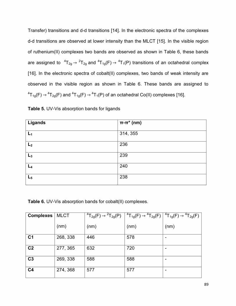
89
Transfer) transitions and d-d transitions [14]. In the electronic spectra of the complexes
d-d transitions are observed at lower intensity than the MLCT [15]. In the visible region
of ruthenium(II) complexes two bands are observed as shown in Table 6, these bands
are assigned to 4T2g 2T2g and 4T1g(F) 4T1(P) transitions of an octahedral complex
[16]. In the electronic spectra of cobalt(II) complexes, two bands of weak intensity are
observed in the visible region as shown in Table 6. These bands are assigned to
4T1g(F) 4T2g(F) and 4T1g(F) 4T1(P) of an octahedral Co(II) complexes [16].
Table 5. UV-Vis absorption bands for ligands
Ligands π-π* (nm)
L1 314, 355
L2 236
L3 239
L4 240
L5 238
Table 6. UV-Vis absorption bands for cobalt(II) complexes.
Complexes MLCT
(nm)
4T2g(F) 2T2g(P)
(nm)
4T1g(F) 4T2g(F)
(nm)
4T1g(F) 4T2g(F)
(nm)
C1 268, 338 446 578 -
C2 277, 365 632 720 -
C3 269, 338 588 588 -
C4 274, 368 577 577 -

90
C5 266, 343 437 437 -
C6 257, 375 470 - 552-638
C7 266, 361 - - -
C8 257, 306 435 - 526
C9 259, 306 443 - 694
C10 269, 365 568 - 657
4.2.1 UV-Vis spectroscopy of metal complexes of bis-(benzimidazolyl)pyridine (L1)
In the spectrum of L1 presented in Figure 25, two intense bands are observed at 313
nm and 343 nm assigned to π- π* transitions of the intra-ligand transitions, similar
observations were reported in literature [17]. The complexes showed intense absorption
in the UV region with two bands at 268 and 338 nm for C1 and at 265 and 358 nm for C6
assigned to MLCT transitions due to dπ(M) to π(ligand) [17]. In the electronic spectrum
of C1, two bands at lower intensity are observed at 446 nm and assigned to 4T2g 2T2g
and 580 nm assigned to 4T1g(F) 4T1(P) to transitions in an octahedral complex [18].
The spectrum of C6 showed two bands at 447 nm assigned to 4T1g(F) 4T1(P) and a
multiple band between 552 and 638 assigned to 4T1g(F) 4T2g(P) transitions, these
bands confirm that the geometry around the metal Co2+ ion is octahedral [16].

91
Figure 25. UV-Vis spectra of L1 and its Ru(II) (C1) and Co(II) (C6) complexes.
4.2.2 UV-Vis spectroscopy of metal complexes of bis-
(butylbenzimidazolyl)pyridine (L2)
The electronic spectrum of L2 (Figure 26), shows a band in the UV region at 236 nm
assigned to π- π* transitions. In the electronic spectra of the complexes, these bands
were observed as two intense bands at 277 and 365 nm for C2 and at 266 and 361 nm
for C7 assigned to MLCT transitions. The spectrum of ruthenium(II) complex, C2 was
observed to show two bands at 632 and 720 nm assigned to 4T2g 2T2g and
4T1g(F) 4T1(P) respectively transitions of an octahedral Ru(II) complex [19]. The
electronic spectrum of C7 does not show any observable d-d transition the reason for
0
0.1
0.2
0.3
0.4
0.5
250 300 350 400 450 500 550 600 650 700 750
Ab
sorb
ance
(a.
u)
Wavelength (nm)
L1
C6
C1
0
0.01
0.02
0.03
0.04
0.05
0.06
0.07
350 450 550 650 750A
bso
rban
ce (
a. u
) Wavelength (nm)

92
this could be the reaction was stopped before the ligands were coordinated to the metal
ion was complete or the complex is soluble in the solvent that was used for synthesis.
Figure 26. UV-Vis spectra of L2 and its Ru(II) (C2) and Co(II) (C7) complexes.
4.2.3 UV-Vis spectroscopy of metal complexes of
bis-(benzylbenzimidazolyl)pyridine (L3)
Figure 27 shows the electronic spectra of L3 and its corresponding metal complexes. In
the spectrum of L3, intense band is observed at 239 nm assigned to π- π* transitions in
the UV region. The complexes showed two bands in the UV region at 269 and 338 nm
for C3 and at 257 and 306 nm for C8 assigned to MLCT. In the electronic spectrum of
C3, a broad band with hyperfine splitting at lower intensity is observed in the range 452-
0
0.2
0.4
0.6
0.8
1
1.2
1.4
1.6
200 300 400 500 600 700
Ab
sorb
ance
(a.
u.)
Wavelength (nm)
L2
C7
C2

93
588 nm assigned to 4T2g 2T2g and 4T1g(F) 4T1(P) transitions [19]. The electronic
spectrum of C8 showed two bands at 435nm assigned to 4T1g(F) 4T1(P) and 526 nm
assigned for 4T1g(F) 4T2g(P), the bands in the visible region confirms the structure of
Co(II) complex to be octahedral [18].
Figure 27. UV-Vis spectra of L3 and its Ru(II) (C3) and Co(II) (C8) complexes.
4.2.4 UV-Vis spectroscopy of metal complexes of bis-(pyrazolyl)pyridine (L4)
The electronic spectrum of L4 shown in Figure 28, with intense bands at 240 nm
assigned to π- π* transitions in the UV region. The complexes show two bands in the
UV region at 259 and 306 nm for C4 and at 257 and 306 nm for C9 assigned to MLCT.
In the electronic spectrum of C4, a broad band is observed at 588 nm assigned to 4T2g
2T2g transition [15,16]. The electronic spectrum of C9 showed two bands at 443 nm
0
0.5
1
1.5
2
2.5
200 250 300 350 400 450 500 550 600 650 700
Ab
sorb
ance
(a.u
.)
Wavelength (nm)
L3
C8
C3
0
0.01
0.02
0.03
0.04
0.05
0.06
0.07
0.08
0.09
0.1
350 450 550 650 750
Ab
sorb
ance
(a.u
)
Wavelength (nm)
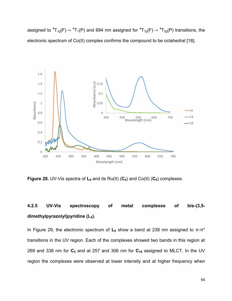
94
assigned to 4T1g(F) 4T1(P) and 694 nm assigned for 4T1g(F) 4T2g(P) transitions, the
electronic spectrum of Co(II) complex confirms the compound to be octahedral [18].
Figure 28. UV-Vis spectra of L4 and its Ru(II) (C4) and Co(II) (C9) complexes.
4.2.5 UV-Vis spectroscopy of metal complexes of bis-(3,5-
dimethylpyrazolyl)pyridine (L5).
In Figure 29, the electronic spectrum of L5 show a band at 238 nm assigned to π-π*
transitions in the UV region. Each of the complexes showed two bands in this region at
269 and 338 nm for C5 and at 257 and 306 nm for C10 assigned to MLCT. In the UV
region the complexes were observed at lower intensity and at higher frequency when
0
0.2
0.4
0.6
0.8
1
1.2
1.4
1.6
200 250 300 350 400 450 500 550 600 650 700
Ab
sorb
ance
Wavelength (nm)
L4
C4
C9
0
0.05
0.1
0.15
350 450 550 650 750
Ab
sorb
ance
(a.
u)
Wavelength (nm)

95
compared to the ligands. The electronic spectrum of C5 shows two bands at 437 nm
assigned to 4T2g 2T2g and 575 nm assigned to 4T1g(F) 4T1(P) transitions [21]. The
electronic spectrum of C10 also shows two bands at 568 nm assigned to 4T1g(F)
4T1(P) and 657 nm assigned for 4T1g(F) 4T2g(P) [18].
Figure 29. UV-Vis spectra of L5 and its Ru(II) (C5) and Co(II) (C10) complexes
4.3 Emission spectroscopy of the complexes.
The emission spectra measurements of Ru(II) and Co(II) complexes recorded in DMSO
solutions were carried out in order to determine the emission properties of cobalt(II) and
0
0.2
0.4
0.6
0.8
1
1.2
1.4
200 250 300 350 400 450 500 550 600
Ab
sorb
ance
(a.
u)
Wavelength (nm)
L5
C10
C5
0
0.005
0.01
0.015
0.02
0.025
0.03
0.035
0.04
350 400 450 500 550 600
Ab
sorb
ance
(a.
u)
Wavelength (nm)

96
ruthenium(II) complexes in a range of 200-900 nm. The complexes show photo
excitation above 400 nm similar to those reported by Chen et al.[21]. The emission of
ruthenium(II) complexes were observed to have a common broad emission bands
above 400 nm with different emission intensities due to electronic transition from the
ground state to the excited state of the metal ions [22].
4.3.1 Emission spectroscopy of Ru(II) complexes
The emission of ruthenium(II) complexes were observed to have a broad emission band
at 703, 703, 705,703 and 704 for C1, C2, C3, C4 and C5 respectively. C1 relative to C2
and C3 red-shifted by 1nm, the red-shift emission is due to the stability of 3MLCT state
by the π-conjugation of L3 [23]. While in C5 blue-shifted by 2nm compared to C4, the
blue-shift is ascribed to lowering of intraligand charge transfer originated from the
LUMO [23, 24] due to electron donating group present in intraligand of C5 [25]. The
emission intensity showed gradual increase with decrease in the molar weight of the
complexes of bis-(imino)pyridine in the order C1>C2>C3 while in the complexes of bis-
(pyrazolyl)pyridine increase in emission intensity was observed with increase in molar
weight of the complexes in the order C5>C4 as shown in Figure 30. The emission of C3
is observed at lower intensity compared to C1 and C2 this is due to while the intensity of
C4 is low compared to C5 is due to molecular weight [26]. The emission for complexes of
bis-(pyrazoly)pyridine is observed at low intensity compared those of bis-
(imino)pyridine, this is due low ligand field excitation state ligands [30]. All the
complexes were observed to show a broad emission ascribed to 3MLCT emission [24]

97
Figure 30. Emission spectra of Ru(II) complexes (C1, C2, C3, C4 and C5)
4.3.2 Photoluminesce (PL) spectroscopy of Co(II) complexes
The photoluminescence emission spectra of cobalt(II) complexes in DMSO solution
were shown in Figure 31. The complexes were observed to exhibit strong photo
emission maxima, C6, C7, C8, C9 and C10 were observed to show excitation at 705, 664,
708, 704 and 705 nm respectively. The complex, C7 relative to C6 and C8 blue-shifted
by 41 nm relative to C6 the blue-shift emission is due to the introduction of alkyl groups
[31]. In the electronic absorption of C7 d-d transition was not observed therefore C7 has
high π* orbital energy hence the lower emission is obtained compared to C6 and C8
[32]. While C8 red-shifted by 3nm, the π-conjugated substituent present on L3 enhanced
the electronic stabilization of the 3MLCT excitation state of the complex [31, 33]. The
0
50
100
150
200
250
660 680 700 720 740
T (%
)
Wavelength (nm)
C1
C2
C5
0
5
10
15
20
25
30
660 680 700 720 740T
(%)
Wavelength (nm)
C3
C4

98
complex, C10 relative to C9 experience a red-shift by 1nm, the red-shift is due to the
alkly substituent on pyrazole that enhanced the π-accepting properties of pyrazole and
caused increase in HOMO-LUMO [34].
Figure 31. Emission spectra of Co(II) complexes (C1, C2, C3, C4 and C5)
0
100
200
300
400
500
620 670 720
T/%
Wavelength/Cm-1
C6
C8
C9
C7
0
2
4
6
8
10
12
670 690 710 730
T/%
Wavelength/cm-1
C10

99
4.4 Electrochemistry of metal complexes.
4.4.1 Electrochemistry of ruthenium(II) complexes.
4.4.1.1 Electrochemistry of ruthenium(II) complexes of bis-(imino)pyridine.
The cyclic voltammogram of ruthenium(II) complexes (Figures 32-34) show the
Ru(II)/Ru(III) redox couple at positive and negative potentials. The oxidation peaks were
not visible in the cyclic voltammogram of C1, C2 and C3. At the cathodic potential,
irreversible peak was observed at –1.01 V. The high negative potential is due to
reduction of ligands [35]. While the complexes containing derivatives of bis-
(imino)pyridine showed irreversible reduction peak at -1.00 and -0.99 V for C2 an C7
respectively. The reduction potential ascribed to the presence of a protection group on
the N-atoms of the benzimidazole ring [36]. The high values observed for reduction
potential is ascribed to reduction of ligand [37].
Figure 32. Cyclic voltammetry of C1
-4.00E-05
-2.00E-05
0.00E+00
2.00E-05
4.00E-05
6.00E-05
8.00E-05
1.00E-04
-1.5 -1 -0.5 0 0.5 1 1.5
Cu
rren
t/A
Potential/V
N
COOH
HOOC
N
N
NH
NH
N
Ru
NCS
NCS

100
Figure 33. Cyclic voltammetry of C2
Figure 34. Cyclic voltammetry of C3
-4.00E-05
-2.00E-05
0.00E+00
2.00E-05
4.00E-05
6.00E-05
8.00E-05
1.00E-04
1.20E-04
1.40E-04
1.60E-04
-1.5 -1 -0.5 0 0.5 1 1.5
Cu
rren
t/A
Potential/V
-2.00E-05
-1.00E-05
0.00E+00
1.00E-05
2.00E-05
3.00E-05
4.00E-05
5.00E-05
6.00E-05
7.00E-05
-1.5 -1 -0.5 0 0.5 1 1.5
Cu
rren
t/A
Potential/V
N
COOH
HOOC
N
N
NN
N
Ru
NCS
NCS
N
COOH
HOOC
N
N
NN
N
Ru
NCS
NCS
C4H9 C4H9
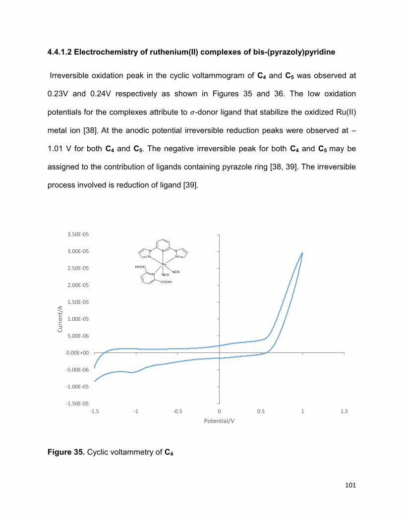
101
4.4.1.2 Electrochemistry of ruthenium(II) complexes of bis-(pyrazoly)pyridine
Irreversible oxidation peak in the cyclic voltammogram of C4 and C5 was observed at
0.23V and 0.24V respectively as shown in Figures 35 and 36. The low oxidation
potentials for the complexes attribute to 𝜎-donor ligand that stabilize the oxidized Ru(II)
metal ion [38]. At the anodic potential irreversible reduction peaks were observed at –
1.01 V for both C4 and C5. The negative irreversible peak for both C4 and C5 may be
assigned to the contribution of ligands containing pyrazole ring [38, 39]. The irreversible
process involved is reduction of ligand [39].
Figure 35. Cyclic voltammetry of C4
-1.50E-05
-1.00E-05
-5.00E-06
0.00E+00
5.00E-06
1.00E-05
1.50E-05
2.00E-05
2.50E-05
3.00E-05
3.50E-05
-1.5 -1 -0.5 0 0.5 1 1.5
Cu
rren
t/A
Potential/V
N
COOH
HOOC
N N
N
N
N
Ru
NCSNCS

102
Figure 36. Cyclic voltammetry of C5
4.4.2 Electrochemistry of cobalt(II) complexes
4.4.2.1 Electrochemistry of cobalt(II) complexes of bis-(imino)pyridine.
Cyclic voltammogram of cobalt(II) complexes show the Co(II)/Co(III) redox couple at
oxidation and reduction potentials. In the cyclic voltammogram of C6 shown in Figure
33, irreversible oxidation peak was observed at -0.42 V ascribed to oxidation of electron
withdrawing group from uncoordinated NH group of benzimidazole [40], while the
reversible oxidation for C7 and C8 (Figures 37 and 39) was observed at -0.38 and -0.29
respectively attribute to the oxidation of ligand. The irreversible oxidation peaks
-2.00E-05
-1.00E-05
0.00E+00
1.00E-05
2.00E-05
3.00E-05
4.00E-05
5.00E-05
6.00E-05
7.00E-05
-1.5 -1 -0.5 0 0.5 1 1.5
Cu
rren
t/A
Potential/V
N
COOH
HOOC
N N
N
N
N
CH3
CH3CH3
CH3
Ru
NCSNCS
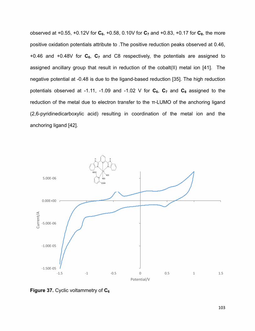
103
observed at +0.55, +0.12V for C6, +0.58, 0.10V for C7 and +0.83, +0.17 for C8, the more
positive oxidation potentials attribute to .The positive reduction peaks observed at 0.46,
+0.46 and +0.48V for C6, C7 and C8 respectively, the potentials are assigned to
assigned ancillary group that result in reduction of the cobalt(II) metal ion [41]. The
negative potential at -0.48 is due to the ligand-based reduction [35]. The high reduction
potentials observed at -1.11, -1.09 and -1.02 V for C6, C7 and C8 assigned to the
reduction of the metal due to electron transfer to the π-LUMO of the anchoring ligand
(2,6-pyridinedicarboxylic acid) resulting in coordination of the metal ion and the
anchoring ligand [42].
Figure 37. Cyclic voltammetry of C6
-1.50E-05
-1.00E-05
-5.00E-06
0.00E+00
5.00E-06
-1.5 -1 -0.5 0 0.5 1 1.5
Cu
rren
t/A
Potential/V
N
COOH
HOOC
N
N
NH
NH
N
Co
NCS
NCS

104
Figure 38. Cyclic voltammetry of C7
-3.00E-05
-2.50E-05
-2.00E-05
-1.50E-05
-1.00E-05
-5.00E-06
0.00E+00
5.00E-06
1.00E-05
-1.5 -1 -0.5 0 0.5 1 1.5
Cu
rren
t/A
Potential/V
N
COOH
HOOC
N
N
NN
N
Co
NCS
NCS
C4H9 C4H9

105
Figure 39. Cyclic voltammetry of C8
4.4.2.2 Electrochemistry of cobalt(II) complexes of bis-(pyrazolyl)pyridine.
In the cyclic voltammogram of C9 and C10 (Figures 40 and 41) irreversible oxidation
peaks were found at 0.41 and 0.77 V respectively, the increase in potential of C10 is due
to electron withdrawing group (-CH3) present on the pyrazole causing the insufficient
electrons in the ligand [42]. The reversible potentials were observed at -1.20 V for C9
and -0.41, -120 V for C10. The high reversible peak ascribed to the oxidation of the
metal [22], in all metal-based oxidation reversible oxidation is experienced [43]. At the
negative reduction peaks were observed at -1.11V for C9 and 0.48,-1.03V for C10. The
-3.00E-05
-2.50E-05
-2.00E-05
-1.50E-05
-1.00E-05
-5.00E-06
0.00E+00
5.00E-06
1.00E-05
-1.5 -1 -0.5 0 0.5 1 1.5
Cu
rren
t/A
Potential/V
N
COOH
HOOC
N
N
NN
N
Co
NCS
NCS

106
high reduction potentials is due to the presence of a pyrazole ring [22, 44] causing the
reduction to take place in the metal ion [41]. The positive reduction observed in the
voltammogram of C10 is related to the red-shift observed in the visible region of C10
spectrum (Figure 33), it can also be ascribed to the ancillary ligand (thiocynate) [41].
Figure 40. Cyclic voltammetry of C9
-2.50E-05
-2.00E-05
-1.50E-05
-1.00E-05
-5.00E-06
0.00E+00
5.00E-06
1.00E-05
-2 -1.5 -1 -0.5 0 0.5 1 1.5
Cu
rren
t/A
Potential/V
N
COOH
HOOC
N N
N
N
N
Co
NCSNCS

107
Figure 41. Cyclic voltammetry of C10
4.5 Solar cell fabrication and current-voltage characterization of N719, and some
synthesized Ru(II) and Co(II) complexes.
The I-V characterization of the cells was performed using semiconductor parameter
analyzer. The results of the cells are obtained from the I-V curves were used to
determine the conversion efficiency of the DSSC of N719, ruthenium(II) and cobalt(II)
complexes, where the solar cell efficiency using the following equation [46]:
-1.50E-05
-1.00E-05
-5.00E-06
0.00E+00
5.00E-06
1.00E-05
-2 -1.5 -1 -0.5 0 0.5 1 1.5
Cu
rren
t/A
Potential/V
N
COOH
HOOC
N N
N
N
N
CH3
CH3CH3
CH3
Co
NCSNCS

108
Where η is the conversion efficiency, Jsc is the short circuit current, FF is the fill factor
and P is the incident light which equals to 0.08 W for N719, C1, C2, C4 and equals to
0.04 W for C5 and C8-C10.
Photographic picture of fabricated solar cells using some ruthenium(II), cobalt(II) and
N719 is presented in Figure 42.
Figure 42. Photographic picture of fabricated solar cells.

109
4.5.1 Current-voltage characterization of N719 dye.
The results of the dye-sensitized solar cell obtained from I-V curve of N719 shown in
Figure 39 were used to determine the efficiency of the cell. The efficiency obtained was
8.85% which was similar to that reported literature [46] where N719 was used in dye-
sensitized solar cell.
Figure 43. I-V curve of N719 dye-sensitized solar cell using I-3/I- electrolyte
4.5.2 Current-voltage characterization of ruthenium(II) complexes.
The solar conversion efficiencies of the ruthenium dyes, C1, C2, C4 and C5 presented in
Table 8, were obtained from the I-V curves shown in Figures 44-47. Complex, C3 was
not characterized because of its low yield. The efficiencies of the ruthenium complexes
0
0.0005
0.001
0.0015
0.002
0.0025
0.28 0.38 0.48 0.58 0.68 0.78
Cu
rren
t/A
Potential/V
η= 8.85%
FF= 0.494
Voc = 0.717 V
Jsc = 4.95mA/cm-2

110
were very low compared to the N719, dye which was used as the standard dye in solar
cell characterization. Complexes that consist of bis-(pyrazolyl)pyridine, C5, showed the
highest efficiency (1. 01×10-3 %).
Table 7 I-V characterization of ruthenium complexes
Complex Jsc/ mAcm-2 Voc/ mV Pmax FF (η)
C1 0.191 5.93 × 10⁻³ 0.09 × 10⁻³ 0.787 9.8 x10⁻⁵
C2 0.0176 14.3 × 10⁻³ 0.0171 × 10⁻³ 0.679 19.0x10⁻⁵
C4 0.199 37.0 × 10⁻³ 0.0442 × 10⁻³ 0.598 49.1 x10⁻⁵
C5 0.022 87.3 × 10⁻³ 0.0908 × 10⁻³ 0.517 101.0x10⁻⁵
Figure 44. I-V curve C1 dye-sensitized solar cell using I-3/I- electrolyte
0
0.000005
0.00001
0.000015
0.00002
0.000025
0 0.005 0.01 0.015 0.02 0.025
Cu
rren
t/A
Potential/V

111
Figure 45. I-V curve of C2 dye-sensitized solar cell using I-3/I- electrolyte
Figure 46. I-V curve of C3 dye-sensitized solar cell using I-3/I- electrolyte
0
0.000002
0.000004
0.000006
0.000008
0.00001
0.000012
0.000014
0.000016
0.000018
0.00002
0 0.005 0.01 0.015 0.02 0.025 0.03
Cu
rren
t/A
Potential/V
0
0.000005
0.00001
0.000015
0.00002
0.000025
0 0.01 0.02 0.03 0.04 0.05 0.06
Cu
rren
t/A
Potential/V

112
Figure 47. I-V curve of C5 dye-sensitized solar cell using I-3/I- electrolyte
4.5.2 Current-voltage characterization of cobalt(II) complexes.
Table 9 show the solar conversion efficiencies of cobalt(II) dyes, C8, C9, and C10
obtained from the I-V curves represented in Figures 48-50. The solar conversion
efficiency of cobalt(II) complexes were very low when compared to N719 and the Ru(II)
complexes. The efficiency of the complexes was between 0.60 x10⁻⁵ and 1.5 x10⁻⁵.The
I-V characterization complex C6 was not done because it was lighter in colour and also
C7 was not characterized because the d-d transition was not obtained in the electronic
spectroscopy. The I-V curves were showing unusual results with coiled graphs which
might be due to freshly prepared solar cells.
0
0.000005
0.00001
0.000015
0.00002
0.000025
0 0.02 0.04 0.06 0.08 0.1
Cu
rren
t/A
Pontential/V

113
Table 8. I-V characterization of cobalt complexes
Complex Jsc Voc Pmax FF (η)
C8 0.00283 0.049 × 10⁻³ 0 2.93 1.0 x10⁻⁵
C9 0.00347 0.016 × 10⁻³ 0.001 × 10⁻³ 11.35 1.5 x10⁻⁵
C10 0.00119 0.161 × 10⁻³ 0.005 × 10⁻³ 1.64 0.60 x10⁻⁵
Figure 48. I-V curve of C8 dye-sensitized solar cell using I-3/I- electrolyte
0
0.0000005
0.000001
0.0000015
0.000002
0.0000025
0.000003
0.00004 0.00005 0.00006 0.00007 0.00008 0.00009 0.0001 0.00011 0.00012 0.00013 0.00014
Cu
rren
t/A
Potential/V

114
Figure 49. I-V curve of C9 dye-sensitized solar cell using I-3/I- electrolyte
Figure 50. I-V curve of C10 dye-sensitized solar cell using I-3/I- electrolyte
0
0.0000005
0.000001
0.0000015
0.000002
0.0000025
0.00003 0.00004 0.00005 0.00006 0.00007 0.00008 0.00009 0.0001
Cu
rren
t/A
Potential/V
0
0.0000005
0.000001
0.0000015
0.000002
0.0000025
0.000003
0.0000035
0 0.00005 0.0001 0.00015 0.0002 0.00025
Cu
rren
t/A
Pontential/V

115
The efficiency of ruthenium(II) and cobalt(II) complexes was very low compared to the
standard dye. The Voc and Jsc were very low and the solar conversion efficiency is
dependent on the two factors [47]. The poor values of these factors tend to decrease
efficiency of cells and the decrease in efficiency is probably due to poor adsorption of
the dye onto the surface of the TiO2 semiconductor. The reason for poor adsorption
might be the anchoring ligand, the carboxylic groups were not strong enough to attach
onto the surface of the semiconductor. Moreover, the other reason might be the
carboxylic groups are too close to the metal ion and the electrons could not freely move
through the dye to the semiconductor. The structure of the dye strongly affects the
efficiency of the DSSC [25, 46].
The electrolyte is also the most important component in dye-sensitized solar cells [20,
25]. During fabrication of solar cells there was a discharge of electrolyte from the cells. It
was difficult to fill the TiO2 semiconductor area properly with the electrolyte, which could
also be the reason for low efficiency. The dye sensitizer regeneration depends on the
electrolyte and the role of the electrolyte is to sustain redox cycle of dye for continuous
performance in light for a longer time [20]. The results obtained show the correlation
between photophysical and electrochemical properties of the complexes used for
DSSCs. The ruthenium complex, C5 obtained the highest energy efficiency compared to
other complexes, this is due to properties of pyrazolyl ligands [47].

116
References
[1] Ashraful, A.; Hironori, A. Molecular design of ruthenium(II) polypyridyl
photosensitizer for efficient nanocrystalline TiO2 solar cells. Journal of Photochemistry
and Photobiology A: Chemistry, 2003, 158, 131-138.
[2] Wang, G. L.; Jiao, H. J.; Liu, K. L.; Wu, X. M.; Dong, Y. M.; Li, Z. J.; Zhang, J. A
novel strategy for the construction of photoelectrochemical sensors based on quantum
dots and electron acceptor: The case of dopamine detection. Electrochemistry
Communications, 2014, 41, 47-50.
[3] Kuchison, A. M.; Wolf, M. O.; Patrick, B. O. Photophysical and electrochemical
properties of Ru(II) complexes containing tridentate bis-(phosphino-oligothiophene)
ligands. Dalton Transactions, 2011, 40, 6912-6921.
[4] Ding, J.; Li, Y.; Hu, H.; Bai, L.; Zhang, S.; Yuan, N. The influence of anatase-rutile
mixed phase and ZnO blocking layer on dye-sensitized solar cells based on TiO2
nanofiber photoanodes. Nanoscale Research Letters, 2013, 8, 1-9.
[5] Cheng M. H.; Hsieh, W. F. High-efficiency metal-free organic-dye-sensitized solar
cells with hierarchical ZnO photoelectrode, Energy and Environmental Sciences, 2010,
3, 442-447.
[6] Kuang, D.; Ito, S.; Wenger, B.; Klein, C.; Moser, J. E.; Humphry-Baker, R.;
Zakeeruddin, S. M.; Gratzel, M. High molar extinction coefficient heteroleptic ruthenium
complexes for thin film dye-sensitized solar cells. Journal of the American Chemistry
Society, 2006, 128, 4146-4154.

117
[7] Amlan K. Pal, A. K.; Serroni, S.; Zaccheroni, N.; Campagna, S.; Hanan, G. S. Near
infra-red emitting Ru(II) complexes of tridentate ligands: Electrochemical and
photophysical consequences of a strong donor ligand with large bite angles. Journal of
Chemical Science, 2014, 5, 4800-4811
[8] DeRosa, M. C.; Crutchley, R. J. Photosensitized singlet oxygen and its applications.
Coordination Chemistry Reviews, 2002, 233-234, 351-371.
[9] Pellegrin, Y.; Pleux, L. E.; Blart, L.; Renaud, A.; Chavillon, B.; Szuwarski, N.;
Boujtita, M.; Cario, L.; Jobic, S.; Jacquemin, D.; Odobel, F. Ruthenium polypyridine
complexes as sensitizers in NiO based p-type dye-sensitized solar cells: Effects of the
anchoring groups. Journal Photochemistry and Photobiology A: Chemistry, 2011, 219,
235-242.
[10] Wu, Y.; Zhu, W. Organic dye sensitizers from D-π-A to D-A-π-A: Effects of internal
electron-withdrawing units on molecular absorption, energy level and photovoltaic
performance. Chemical Society Reviews, 2013, 12, 2039-2058.
[11] Lobello, M. G.; Wu, K. L.; Reddy, A. M.; Marotta, G.; Gratzel, M.; Nazeeruddin. M.
K., Chi, Y.; Chandrasekharam, M.; Vitillaro, G.; De Angelis, F. Engineering of Ru(II)
dyes for interfacial and light-harvesting optimization. Dalton Transactions, 2014, 43,
2726-2732.
[12] Adeloye, A. O.; Olomola, T. O.; Adebayo, A. I.; Ajibade, P. A. A high molar
extinction coefficient bisterpyridyl homoleptic Ru(II) complex with trans-2-methyl-2-
butenoic acid functionality: Potential dye for dye-sensitized solar cells, International
Journal of Molecular Science, 2012, 13, 3511-3526.

118
[13] Liu, J.; Li, J. Electrochemical analysis of dye adsorption on aligned carbon
nanofiber arrays coated with TiO2 nanoneedles for dye-sensitized solar cell. Frontiers of
Optoelectronics in China, 2011, 4, 53-58.
[14] Jamson, D. L.; Goldsby, K. A. 6-bis-(N-pyrazolyl)pyridines: the convenient
synthesis of a family of planar tridentate N3 ligands that are terpyridine analogs. Journal
of Organic Chemistry, 1990, 55, 4992-4994.
[15] Ajibade, P. A.; Kolawole, G. A. O’Brien, P.; Helliwell, M.; Raftery, J. Cobalt(II)
complexes of the antibiotic sulfadiazine, the X-ray single crystal structure of
[Co(C10H9N4O2S)2(CH3OH)2]. Inorganica Chimica Acta, 2006, 359, 3111-3116.
[16] Ajibade, P. A., Kolawole, G. A. Synthesis, characterization, antiplasmodial and
antitrypanosomal activity of some metal(III) complexes of sulfadiazine. Bulletin of the
Chemical Society of Ethiopia, 2008, 22, 261-268.
[17] Ahmadi, R. A.; Hasanvand, F.; Bruno, G.; Rudbari, H. A.; Amani, S. Synthesis,
spectroscopy, and magnetic characterization of copper(II) and cobalt(II) complexes with
2-amino-5-bromopyridine as ligand. ISRN Inorganic Chemistry, 2013, 426, 712-720.
[18] Alsindi, W. Z.; Sun, X-Z.; George, M. W. Excited state dynamics of metal-
bipyrimidine complexes studied by time-resolved infrared spectroscopy. Central Laser
Facility Annual Report, 2005/2006, 169-171.
[19] Deng, H.; Yu, Z.; Dong, J.; Wu, S. 2,6-Bis(3,5-dimethylpyrazol-1-yl)pyridine: A
useful pseudo-N3 ligand in efficient ruthenium(II)-catalyzed transfer hydrogenation of
ketones , Organometallics, 2005, 24, 4110-4112.

119
[20] Adeloye, A. O.; Ajibade, P. A.; Cummings, F. R.; Le Roux, L. J.; Mamphweli, S. N.;
Meyer E. L. Synthesis, photophysical and preliminary investigation of the dye-sensitized
solar cells properties of functionalized anthracenyl-based bipyridyl and phenanthrolyl
Ru(II) complexes. Journal of Chemical Sciences, 2013, 125, 17-27.
[21] Elise, D.; Buriez, O.; Labbe, E.; Verpeaux, J. N.; Amatore, C. Design and
electrochemical characterization of a new cobalt(II)–cyclodextrin complex. Evidence for
a supramolecular stabilization of the Co(I) state. Electrochemistry Communications,
2009, 11, 114-117.
[22] Cheng, F.; Tang, N. A new family of dinuclear Ru(II) polypyridyl complexes
containing dibenzo-14-crown-4. Inorganic Chemistry Communications, 2008, 11, 939-
942.
[23] Tyson, D. S.; Luman, R. C.; Zhou, X.; Castellano. F. N. New Ru(II) chromophores
with extended excited-state lifetimes. Inorganic Chemistry, 2001, 40, 4063-4071.
[24] Ji, S.; Wu, W.; Wu, W.; Song, P.; Han, K.; Wang, Z.; Liu, S.; Guo, H.; Zhao, J.
Tuning the luminescence lifetimes of ruthenium(II) polypyridine complexes and its
application in luminescent oxygen sensing. Journal of Material Chemistry, 2010, 20,
1953-1963.
[25] Adeloye, O. A; Ajibade, P. A. Synthesis, characterization and preliminary
investigation of electro redox properties of anthracenyl-functionalizes terpyridyl ligands.
Tedrahrdron letters. 2011, 52, 274-277.

120
[26] Adeloye, A. O.; Ajibade, P. A. Synthesis and characterization of a Ru(II) complex
with functionalized phenanthroline ligands having single-double linked anthracenyl and
1-methoxy-1-buten-3-yne moieties. Molecules, 2010, 15, 7570-758.
[27] Machura, B.; Switlicka, A.; Penkala, M. N- and S-bonded thiocyanate copper(II)
complexes of 2,6-bis-(benzimidazolyl)pyridine. Synthesis, spectroscopic
characterization, X-ray structure and DFT calculations. Polyhedron, 2012, 45, 221–228
[28] Tripathi, P. N.; Verma, S.; Singh, R. P. Photochemical and electrochemical
properties of tetranuclear Ru (II) complexes. Recent Research in Science and
Technology, 2012, 21-27.
[29] Moehl, T.; Tsao, N. H.; Wu, K.L.; Hsu, H. C.; Chi, Y. L.; Ronca, E.; De Angelis, F.;
Nazeeruddin, M. K.; Gratzel, M. High open-circuit voltages: Evidence for a sensitizer-
induced TiO2 conduction band shift in Ru(II)-dye sensitized solar cells. Chemistry of
Materials, 2013, 25, 4497−4502.
[30] Muller, G.; Riehl, J. P.; Schenk, K. J. S.; K. J.; Hopfgartner, G.; Piguet, C.; Bunzli,
J. C. B. Lanthanide triple helical complexes with a chiral bis(benzimidazole)pyridine
derivative. European Journal of Inorganic Chemistry, 2002, 5, 3101-3110.
[31] Baitalik, S.; Dutta, S.; Biswas, P.; Florke, U.; Bothe, E.; Nag, K. Structural,
Spectroscopic, and proton-coupled electron-transfer behavior of pyrazolyl-3,5-
bis(benzimidazole)-bridged HOMO- and heterochiral Ru(II)Ru(II), Os(II)Os(II), and
Os(II)Ru(II)2,2-Bipyridine Complexes. European Journal of Inorganic Chemistry, 2010,
570–588

121
[32] Zhang, X.; Chen, L.; Li, L.; Mao, J.; Wu, W.; Agren, H.; Hua, J. Photovoltaic
properties of bis-(octyloxy)benzo-[c][1,2,5]thiadiazole sensitizers based on N,N-
diphenylthiophen-2-amine donor. Journal of Materials Chemistry, 2014, 2, 4063-4072.
[33] Kim, J. J.; Yoon, J. A new ruthenium containing dipyridylamine ligand for effective
nanocrystalline dye-sensitized solar cells. Inorganic Chimica Acta, 2013, 394, 506-511.
[34] Xun Jin Zhu, X. J.; Holliday, B. J. Electropolymerization of a ruthenium(ii)
bis(pyrazolyl)pyridine complex to form a novel ru-containing conducting metallopolymer.
Macromolecular Rapid Communications, 2010, 31, 904–909.
[35] Petoud, S.; Buinzli, J. C. G.; Schenk, K. J.; Piguet, C. Luminescent properties of
lanthanide nitrato complexes with substituted bis(benzimidazolyl)pyridines. Inorganic
Chemistry, 1997, 36, 1345-1353
[36] Wu, H, L.; Yuan, J. K.; Huang,X. C.; Kou, F.; Liu, B.; Jia, F.; Wang, K. T.; Bai. Y.
Two zinc(II) and cadmium(II) complexes based on the V-shaped ligand 2,6-bis(2-
benzimidazolyl)pyridine: Synthesis, crystal structure, DNA-binding properties and
antioxidant activities. Inorganica Chimica Acta, 2012,390, 12–21.
[37] Yum, J.; Baranoff, E.; Kessler, F.; Moehl, T.; Ahmad, S.; Bessho, T.; Marchioro, A.; Ghadiri,
E.; Moser, J. E.; Yi, C.; Nazeeruddin, M. K.; Gratzel, M. A cobalt complex redox shuttle for dye-
sensitized solar cells with high open-circuit potentials. Nature communications, 2012, 3, 631-
638.
[38] Jamson, D. L.; Goldsby, K. A. 6-bis(N-pyrazolyl)pyridines: The convenient
synthesis of a family of planar tridentate N3 ligands that are terpyridine analogs. Journal
of Organic Chemistry, 1990, 55, 4992-4994.

122
[39] Gong, D.; Jia, X.; Wang, B.; Zhang, X.; Jiang, L. Synthesis, characterization, and
butadiene polymerization of iron(III),iron(II) and cobalt(II) chlorides bearing 2,6-bis-(2-
benzimidazolyl)pyridyl or 2,6-bis-(pyrazol)pyridine ligand. Journal of Organometallic
Chemistry, 2012, 702, 10-18.
[40] Ole, A. F.; Santos, G. N. C, Quiroga, R. V. Fabrication and characterization of dye
sensitized solar cells using nanostructured TiO2 photoelectrode. International Journal of
Scientific and Engineering Research, 2012, 8, 1-7.
[41] Baheti, A.; Singh, P.; Lee, P. C.; Thomas, K. R. J.; Ho, K. C. 2,7-Diaminofluorene-
based organic dyes for dye-sensitized solar cells: Effect of auxiliary donor on optical
and electrochemical properties. Journal of Organic Chemistry, 2011, 76, 4910-4920
11222.
[42] Yu Chen, Y.; Xu, W. H. ; Kou, K. J.; Yu, B. L.; Wei, X. H.; Chao, H.; Ji, H. N.
Aggregation-induced emission of ruthenium(II) polypyridyl complex [Ru(bpy)2(pzta)]2+.
Journal of Inorganic Chemistry Communications, 2010, 13, 1140-1143
[43] Andre, S. P.; Melina, K. I.; Yukie, M. I. N. Metal complex sensitizers in dye
sensitized solar cells. Coordination Chemistry Reviews, 2004, 48, 1343-136.
[44] Vougioukalakis, G. C.; Stergiopoulos, T.; Kantonis G.; Kontos, A. T.;
Papadopoulos, K.; Arta Stublla. A.; Pierre G.; Potvin. P. G.; Falaras, P. Terpyridine- and
2,6-dipyrazinylpyridine-coordinated ruthenium(II) complexes: Synthesis,
characterization and application in TiO2-based dye-sensitized solar cells. Journal of
Photochemistry and Photobiology A: Chemistry, 2010, 214, 22-32.
123
[45] Wang, Z. H.; Kawauchi, H.; Kashima, T.; Arakawa, H. Significant influence of TiO2
photo electroctrode morphology on the energy conversion efficiency of N719 dye-
sensitized solar cell. Journal of Coordination Chemistry, 2004, 248, 1381-1389.
[46] Wu, K. L.; Li, C. H.; Chi, Y.; Clifford, J. N.; Cabau, L.; Palomares, E.; Cheng, Y. M.;
Pan, H. A.; Chou, T. P. Dye molecular structure device open-circuit voltage correlation
in Ru(II) sensitizers with heteroleptic tridentate chelates for dye-sensitized solar cells.
Journal of the American Chemical Society, 2012, 134, 7488-96.
[47] Kim, D. H.; Lesego, M. D.; Hanson, K.; Alibabaei, L.; Lee, K.; Meyer, T. J.; Parsons,
G. N. Stabilizing chromophore binding on TiO2 for long-term stability of dye-sensitized
solar cells using multicomponent atomic layer deposition. Physical chemistry, 2014, 16,
8615-8622.

124
Chapter 5
5.0 Conclusions and future work.
5.1 Conclusions
Five ligands consisting of 2,6-bis-(benzimidazolyl)pyridine (L1) and its two derivatives
(L2 and L3), 2,6-bis-(pyrazoly)pyridine (L4 and L5) and their corresponding ten
complexes containing five ruthenium(II) and five cobalt(II) complexes were successfully
synthesized. All the compounds were characterized by elemental analysis, conductivity
measurements, melting point, FTIR and NMR spectroscopy. All the ligands and
complexes are soluble in water and DMSO, and are non-electrolyte in solution.
Spectroscopic studies were used to confirm successful synthesis of the ligands and the
metal complexes. FTIR spectra of the complexes confirmed the coordination of the
metal ions through the nitrogen atoms. NMR spectroscopy was used to confirm the
structure of the ligands and complexes but characterization of L1-L3 and some
complexes using NMR was not possible due to poor solubility in almost all the solvents.
The photophysical and electrochemical studies of the ruthenium(II) and cobalt(II)
complexes were carried out using UV-Vis, PL and cyclic voltammogram. The electronic
spectroscopy confirmed the stereochemistry of the complexes to be octahedral, except
for C7 as d-d transition was not visible. Photoluminescence of the complexes was
observed at different wavelengths and appeared similar in all the compounds, the
intensity was found to increase with decreasing molar mass of ruthenium(II) and
cobalt(II) complexes. The complexes show good electrochemical properties except for

125
some ruthenium(II) complex (C1) in which the oxidation potential was not visible in the
cyclic voltammograms. The photophysical and electrochemical properties of the
complexes show that they can be employed as light-harvesting materials for the
fabrication of dyes sensitized solar cells.
Seven complexes containing four ruthenium(II) and three cobalt(II) complexes of 2,6-
bis-(benzimidazolyl)pyridine and 2,6-bis-(pyrazolyl)pyridine ligands were used for solar
cell fabrication and N719 dye was used as the standard dye. The dye-sensitized solar
cells were characterized with solar stimulator. The solar cell efficiency of ruthenium(II)
and cobalt(II) complexes was calculated from the I-V curves of DSSCs. The efficiency of
the complexes was observed to increase with increasing molar weight depending on the
nature of the ligand. Complex, C5 showed the highest efficiency (1.01×10⁻³ %) in all the
complexes that were examined.
The performance of these complexes was very low compared to that of N719 dye which
was used as the standard for this study. The low efficiency of the complexes was due to
low values of Voc and Jsc. The low efficiency of cells can be ascribed to poor electron
injection into the TiO2 semiconductor. This might have been caused by poorly adsorbed
anchoring ligands in which may be link to the orientation of the carboxylic anchoring
group on the metal complexes.

126
5.2 Future Work
Further work needs to be done to modify the ligands and the complexes after synthesis
because some of the ligands were poorly soluble. This can be done by introducing
substituents that will make them more soluble. In electrochemical studies, the use of
different support electrolyte such as tetrabutylammonium hexafluorophosphate (TBAH)
instead of using phosphate buffer solution (PBS) is required especially in
electrochemistry of ruthenium, and use of other solvents instead of water.
Replacement of the anchoring ligands with tridentate (bis-(pyrazolyl)pyridine and bis-
(benzimidazolyl)pyridine) containing a carboxylic acid or phosphonic acid and then try to
compare the efficiency of the complexes. The tridentate ligands with carboxylic or
phosphonic group together with thiocynate ligand could result to higher efficiency. The
use of tridentate ligands will enhance the adsorption of dye onto the surface of the TiO2
semiconductor.
It is necessary to do the current-voltage characterization against time as to observe the
efficiency with time, the results of freshly prepared dye-sensitized solar cells sometimes
give strange I-V curves. To minimize the discharge of electrolyte from the cell, requires
an increase in temperature during the sealing of the cells. This would prevent the
possibility of the cell losing the electrons during characterization. The results must be
taken into account in the design of cobalt complexes as a sensitizer for DSSCs as to
replace ruthenium with most relatively cheaper metal.