Embed Size (px)
Citation preview
D e p a r t m e n t o f C o m p u t e r E n g i n e e r i n g
cad - syntheses - 1© Peeter Ellervee
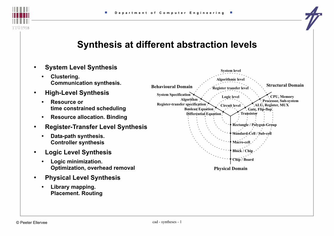
Synthesis at different abstraction levels
• System Level Synthesis• Clustering.
Communication synthesis.
• High-Level Synthesis• Resource or
time constrained scheduling• Resource allocation. Binding
• Register-Transfer Level Synthesis• Data-path synthesis.
Controller synthesis
• Logic Level Synthesis• Logic minimization.
Optimization, overhead removal
• Physical Level Synthesis• Library mapping.
Placement. Routing
System level
Algorithmic level
Register transfer level
Logic level
Circuit level
TransistorGate, Flip-flop
ALU, Register, MUXProcessor, Sub-system
CPU, Memory
Rectangle / Polygon-Group
Standard-Cell / Sub-cell
Macro-cell
Block / Chip
Chip / Board
System SpecificationAlgorithm
Register-transfer specificationBoolean Equation
Differential Equation
Physical Domain
Structural DomainBehavioural Domain
D e p a r t m e n t o f C o m p u t e r E n g i n e e r i n g
cad - syntheses - 2© Peeter Ellervee
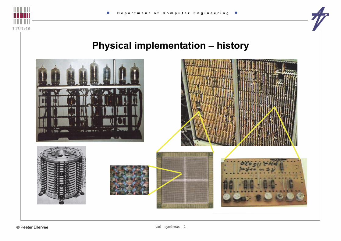
Physical implementation – history

D e p a r t m e n t o f C o m p u t e r E n g i n e e r i n g
cad - syntheses - 3© Peeter Ellervee
Physical implementation – history

D e p a r t m e n t o f C o m p u t e r E n g i n e e r i n g
cad - syntheses - 4© Peeter Ellervee
Chip design and fabrication• Partitioning
• Floorplanning• initial placement
• Placement• fixed modules
• Global routing
• Detailed routing
• Layout optimization
• Layout verification
• Fabrication – http://jas.eng.buffalo.edu/ [e.g., 7.2]
netlist
chip
block
logic cellshttp://www.vlsitechnology.org/
2-NAND 2-NOR 2-2-AND-NOR
flip-flop
Standard cell examples
Transistor chaining
D e p a r t m e n t o f C o m p u t e r E n g i n e e r i n g
cad - syntheses - 5© Peeter Ellervee
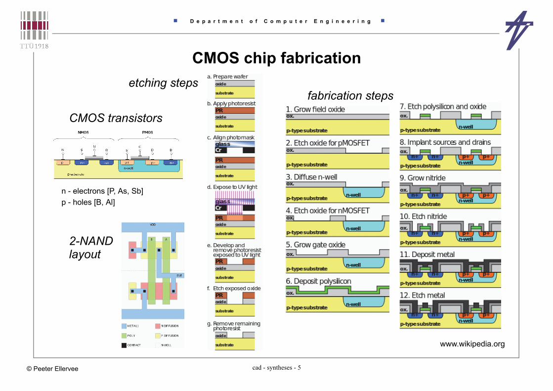
CMOS chip fabrication etching steps
www.wikipedia.org
fabrication steps
2-NAND
CMOS transistors
p - holes [B, Al]n - electrons [P, As, Sb]
layout

D e p a r t m e n t o f C o m p u t e r E n g i n e e r i n g
cad - syntheses - 6© Peeter Ellervee
Packaging examples prototyping
3D assembly
hybrid circuit
IBM POWER5

D e p a r t m e n t o f C o m p u t e r E n g i n e e r i n g
cad - syntheses - 7© Peeter Ellervee
Packaging issues
• Mechanical requirements and constraints• size, interfaces• durability – dust, vibration
• Thermal requirements and constraints• work temperature range• cooling / heating
• Electrical requirements and constraints• power supply• protection – voltage, electromagnetic fields
• Ergonomic requirements and constraints• appearance, user interface, noise
airair
filter/fan case
chipheat sinksupport
crystalgluesubstrate
pin
wire bond
D e p a r t m e n t o f C o m p u t e r E n g i n e e r i n g
cad - syntheses - 8© Peeter Ellervee
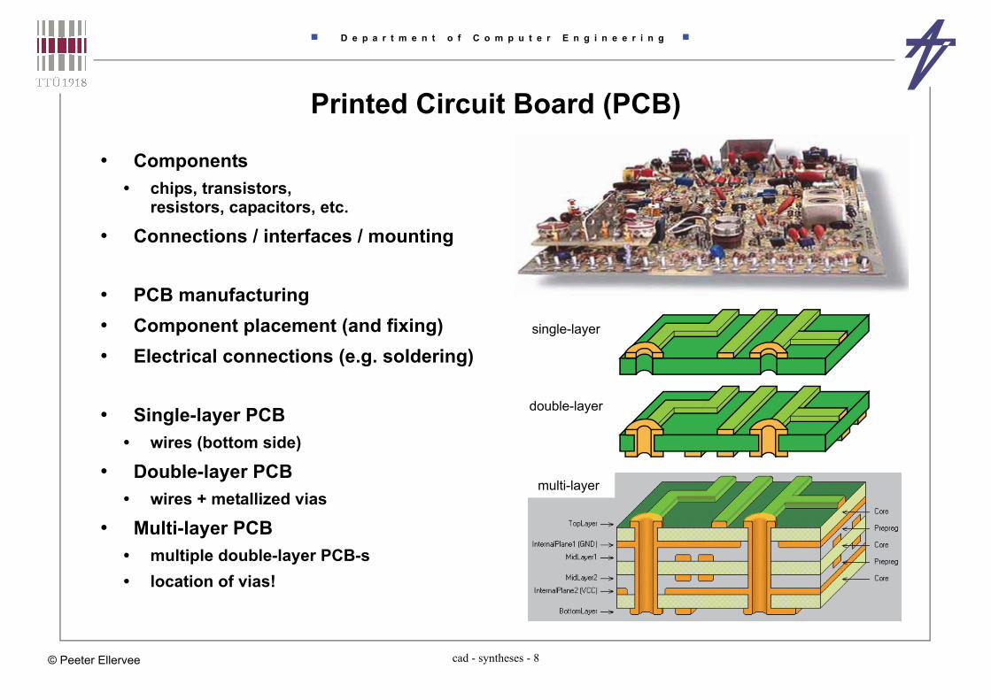
Printed Circuit Board (PCB)
• Components • chips, transistors,
resistors, capacitors, etc.
• Connections / interfaces / mounting
• PCB manufacturing• Component placement (and fixing)• Electrical connections (e.g. soldering)
• Single-layer PCB• wires (bottom side)
• Double-layer PCB• wires + metallized vias
• Multi-layer PCB• multiple double-layer PCB-s• location of vias!
single-layer
multi-layer
double-layer

D e p a r t m e n t o f C o m p u t e r E n g i n e e r i n g
cad - syntheses - 9© Peeter Ellervee
PCB manufacturing
• Manufacturing• component mounting• soldering
• solder paste / tin
• thermal problems• large copper surfaces• component over-heating
• quality check• visual inspection
• final finish• cleaning• protective lacquering
• final test• functional test
Through-hole Wave Soldering
SMD Wave Soldering

D e p a r t m e n t o f C o m p u t e r E n g i n e e r i n g
cad - syntheses - 10© Peeter Ellervee
PCB manufacturing Wave Soldering
SMD Reflow Soldering
GIGABYTE factory tourhttps://www.youtube.com/watch?v=Va3Bfjn4inA
Tutorialhttps://www.youtube.com/watch?v=gu0v8lfLcKg
SMD reflow at homehttps://www.youtube.com/watch?v=U48Nose31d4
Electro Soft Inc.https://www.youtube.com/watch?v=inHzaJIE7-4
Agrowtek Inc.https://www.youtube.com/watch?v=VWH58QrprVc

D e p a r t m e n t o f C o m p u t e r E n g i n e e r i n g
cad - syntheses - 11© Peeter Ellervee
Logic synthesis
• Transforming logic functions (Boolean functions) into a set of logic gates• transformations at logic level from behavioral to structural domain
• Optimizations / Transformations• area• delay• power consumption
• Implementation of Finite State Machines (FSM)• state encoding• generating next state and output functions• optimization of next state and output functions

D e p a r t m e n t o f C o m p u t e r E n g i n e e r i n g
cad - syntheses - 12© Peeter Ellervee
Logic synthesis – main tasks
• Optimization of representation of logic functions• minimization of two-level representation• optimization of binary decision diagrams (BDD)
• Synthesis of multi-level combinational nets (circuits)• optimizations for area, delay, power consumption, and/or testability
• Optimization of state machines• state minimization, encoding
• Synthesis of multi-level sequential nets (circuits)• optimizations for area, delay, power consumption, and/or testability
• Library mapping• optimal gate selection

D e p a r t m e n t o f C o m p u t e r E n g i n e e r i n g
cad - syntheses - 13© Peeter Ellervee
Register-transfer level synthesisDigital system @RTL = data-path + controller
• Transformation from RT-level structural description to logic level description• Data-path – storage units (registers, register files, memories) and combinational units
(ALU-s, multipliers, shifters, comparators etc.), connected by buses• Data path synthesis – maximizing the clock frequency, retiming, operator selection
• Controller – Finite State Machine (FSM) – state register and two combinational units (next state and output functions)
• Controller synthesis – architecture selection, FSM optimizations, state encoding, decomposition
inputs / outputs
control
+
&
>
Ssignals
clock

D e p a r t m e n t o f C o m p u t e r E n g i n e e r i n g
cad - syntheses - 14© Peeter Ellervee
Data-path optimization
A B
comp
mux
C
A[7]
data flow onlyread_port(A);read_port(B);if A(7)=’0’ then if A>B then C := A;
else C := B;
end if;else if A>B then C := B;
else C := A;
end if;end if;
if F=0 then B := A + C else B := C - 1; (w/o controller)
+
B
CF
A 111...1

D e p a r t m e n t o f C o m p u t e r E n g i n e e r i n g
cad - syntheses - 15© Peeter Ellervee
Data-path optimization• Hardware cost of an operation
• shifting == rerouting wires• the same functional unit for addition and subtraction – adder (+carry)
• Independent operations can be executed simultaneously• analysis of real data dependencies, e.g., result of shifting R2
+x1
false
R2 := 0.R2[15.1]
R3 := R3 + R2 R3 := R3 - R2
C := C + 1
y1
y2 y3
y4
true
y1, y2, y4
R2
y1
>>
R3y2
not
x1
+
Cy4
1

D e p a r t m e n t o f C o m p u t e r E n g i n e e r i n g
cad - syntheses - 16© Peeter Ellervee
Arithmetic unit architecture selection• Parallel versus sequential execution
• Adder/subtracter architectures• ripple-carry – sequence of full-adders, small but slow• carry-look-ahead – separate calculation of carry generation and/or propagation
• generation: gi=ai·bi ; propagation: pi=ai+bi ; carry: ci=gi+pi·ci-1
• carry-select adders – duplicated hardware plus selectors• speculative calculation one case with carry and another without,
the answer will be selected when the actual carry has arrived
• Multiplier architectures• sequential algorithms – register + adder, 1/2/... bit(s) at a time• “parallel” algorithms – array multipliers – AND gates + full-adders
• Multiplication/division with constant• shift+add – 5*n = 4*n + n = (n<<2) + n

D e p a r t m e n t o f C o m p u t e r E n g i n e e r i n g
cad - syntheses - 17© Peeter Ellervee
http://www.ecs.umass.edu/ece/koren/arith/simulator

D e p a r t m e n t o f C o m p u t e r E n g i n e e r i n g
cad - syntheses - 18© Peeter Ellervee
Controller synthesis
• Controller == Finite State Machine (FSM)
• Controller synthesis is also a task at the algorithmic level. Controller is the implementation of the operation scheduling task in hardware.
• The canonical implementation of a sequential system is based directly on its state description. It consists of state register, and a combinational network to implement the transition and output functions.
• Sub-tasks• generation of the state graph• selecting the proper controller architecture• finite state machine optimization for area, performance, testability, etc.

D e p a r t m e n t o f C o m p u t e r E n g i n e e r i n g
cad - syntheses - 19© Peeter Ellervee
FSM encoding• Input/output encoding – symbols –> binary code
• State encoding – states –> binary code
• z – number of symbols/states –> minimum code length is t=ceil(log2z)
• Two border cases – minimal code length encoding & one-hot-encoding
• General encoding strategy• Identification of sets of states (adjacent groups) in the state table such that, if encoded
with the minimal Hamming distance, lead to a simplification of the corresponding next-state and output equations after logic minimization.
• The groups and their intersections are analyzed with the respect of the degree of potential minimizations during the subsequent logic minimization. Results are reflecting the potential gains in the cost of the final logic.
• Coding constraints and calculated gains control the encoding heuristics which try to satisfy as much constraints as possible.

D e p a r t m e n t o f C o m p u t e r E n g i n e e r i n g
cad - syntheses - 20© Peeter Ellervee
FSM architectures
Stack architecture
1 2 3
a
b c
d
call return C
d
OI
q q+
pushpop
Counter
1 a b
-/start
C
counter
OI
start/ncnt/cntrdy
a b 2
-/ncnt rdy/-
rdy/cnt
1 a b 2
Register architecture
1 2 3
a
b c
d
call return
C
d
OI
q q+
load
data
1 2 3
a
b c
d
7 8 9
x
w
Ms
Mm
789v
Decomposed
MmO
CSm
Ms
CSs CI
architecture
architecture

D e p a r t m e n t o f C o m p u t e r E n g i n e e r i n g
cad - syntheses - 21© Peeter Ellervee
High-Level Synthesisa.k.a. Behavioral Synthesis a.k.a. Algorithm Level Synthesis
a.k.a. Silicon Compilation
• High-Level Synthesis (HLS) takes a specification of the functionality of a digital system and a set of constraints, finds a structure that implements the intended behavior, and satisfies constraints
• Front-end tasks:• Mapping PL/HDL decription into internal graph-based representation• Compiler optimizations
• Back-end tasks:• Behavioral transformations• Essential subtasks – transforming data and control flow into RT level structure
• scheduling – time or resource constrained• resource allocation – functional units, storage elements, interconnects• resource assignment (binding) – functional units, storage elements, interconnects
• Netlist extraction, state machine table generation

D e p a r t m e n t o f C o m p u t e r E n g i n e e r i n g
cad - syntheses - 22© Peeter Ellervee
Target• SW synthesis (compilation)
• input – high-level programming language• output – sequence of operations (assembler code)
• HW synthesis (HLS)• input – hardware description language• output – sequence of operations (microprogram)• output – RTL description of a digital synchronous system (i.e., processor)
• data part & control part• communication via flags and control signals• discrete time steps (for non-pipelined designs time step = control step)
• Creating the RTL structure means mapping the data and control flow in two dimensions – time and area

D e p a r t m e n t o f C o m p u t e r E n g i n e e r i n g
cad - syntheses - 23© Peeter Ellervee
Scheduling• Scheduling – assignment of operations to time (control steps),
possibly within given constraints and minimizing a cost function• transformational and constructive algorithms• use potential parallelism, alternation and loops• many good algorithms exist, well understood
• Resource constrained scheduling (RCS)• List scheduling
• Time constrained scheduling (TCS)• ASAP – “as soon as possible” / ALAP – “as late as possible”• ASAP and ALAP scheduling are used for• Force directed scheduling
• Neural net based schedulers
• Path-based / path traversing scheduling (AFAP)
D e p a r t m e n t o f C o m p u t e r E n g i n e e r i n g
cad - syntheses - 24© Peeter Ellervee
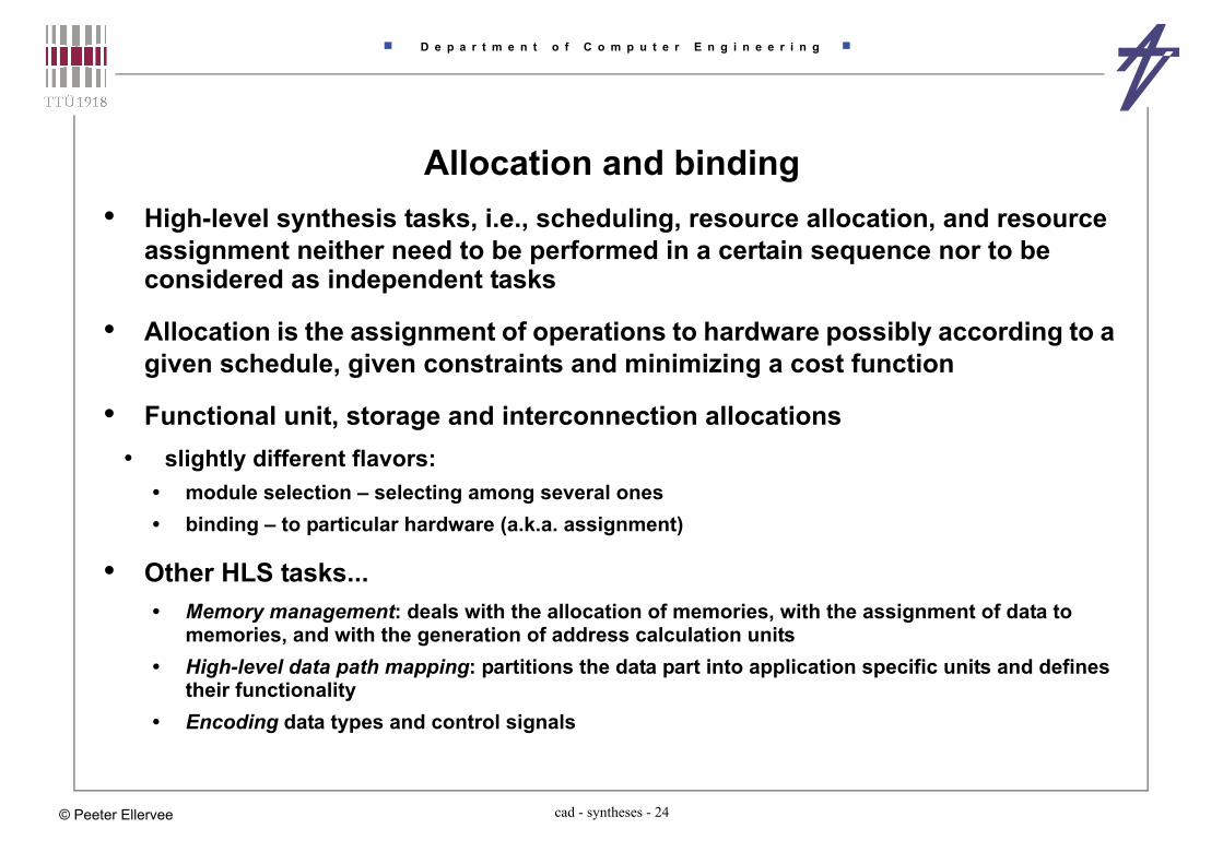
Allocation and binding• High-level synthesis tasks, i.e., scheduling, resource allocation, and resource
assignment neither need to be performed in a certain sequence nor to be considered as independent tasks
• Allocation is the assignment of operations to hardware possibly according to a given schedule, given constraints and minimizing a cost function
• Functional unit, storage and interconnection allocations• slightly different flavors:
• module selection – selecting among several ones• binding – to particular hardware (a.k.a. assignment)
• Other HLS tasks...• Memory management: deals with the allocation of memories, with the assignment of data to
memories, and with the generation of address calculation units• High-level data path mapping: partitions the data part into application specific units and defines
their functionality• Encoding data types and control signals

D e p a r t m e n t o f C o m p u t e r E n g i n e e r i n g
cad - syntheses - 25© Peeter Ellervee
Completing the Data Path• Subtasks after scheduling
• Allocation • Allocation of FUs (if not allocated before scheduling)• Allocation of storage (if not allocated before scheduling)• Allocation of busses (if buses are required and not allocated in advance)
• Binding (assignment)• Assignment of operations to FU instances
(if not assignment before scheduling as in the partitioning approach)• Assignment of values to storage elements• Assignment of data to be transferred to buses (if busses are used)
• Allocation and binding approaches• Rule based schemes (Cathedral II), used before scheduling• Greedy (e.g., Adam)• Iterative methods• Branch and bound (interconnect levels)• Integer linear programming (ILP)• Graph theoretical (clicks, node coloring)

D e p a r t m e n t o f C o m p u t e r E n g i n e e r i n g
cad - syntheses - 26© Peeter Ellervee
Pipelining• Pipelining - an implementation technique whereby multiple instructions are
overlapped in execution
• Latency (L) - total number of time units needed to complete the computation on one input sample
• Sample rate (R) - the number of time units between two consecutive initiations, where initiation is the start of a computation on an input sample
• A (pipe) stage is a piece of HW that is capable of executing certain subtask of the computation
• The reservation table is a two-dimensional representation of the data flow during one computation. One dimension corresponds to the stages, and the other dimension corresponds to time units.
• Actions in pipeline: flushing, refilling, stalling.

D e p a r t m e n t o f C o m p u t e r E n g i n e e r i n g
cad - syntheses - 27© Peeter Ellervee
Pipeline - example
Stag
e 1
Stag
e 2
Stag
e 3
Stag
e 4
[s1]T1
[s2]T2
[s3]T3
[s4]T4
[s2]T5
[s1]T6
[s1]T1
[s2]T2
[s3]T3
[s4]T4
[s2]T5
[s1]T6
[s1]T1
[s2]T2
[s3]T3
[s4]T4
[s2]T5
[s1]T6
[s1]T1
[s2]T2
[s3]T3
[s4]T4
[s2]T5
[s1]T6
samples
time
samplerate
latency
subtasks
pipeline flushed
D e p a r t m e n t o f C o m p u t e r E n g i n e e r i n g
cad - syntheses - 28© Peeter Ellervee
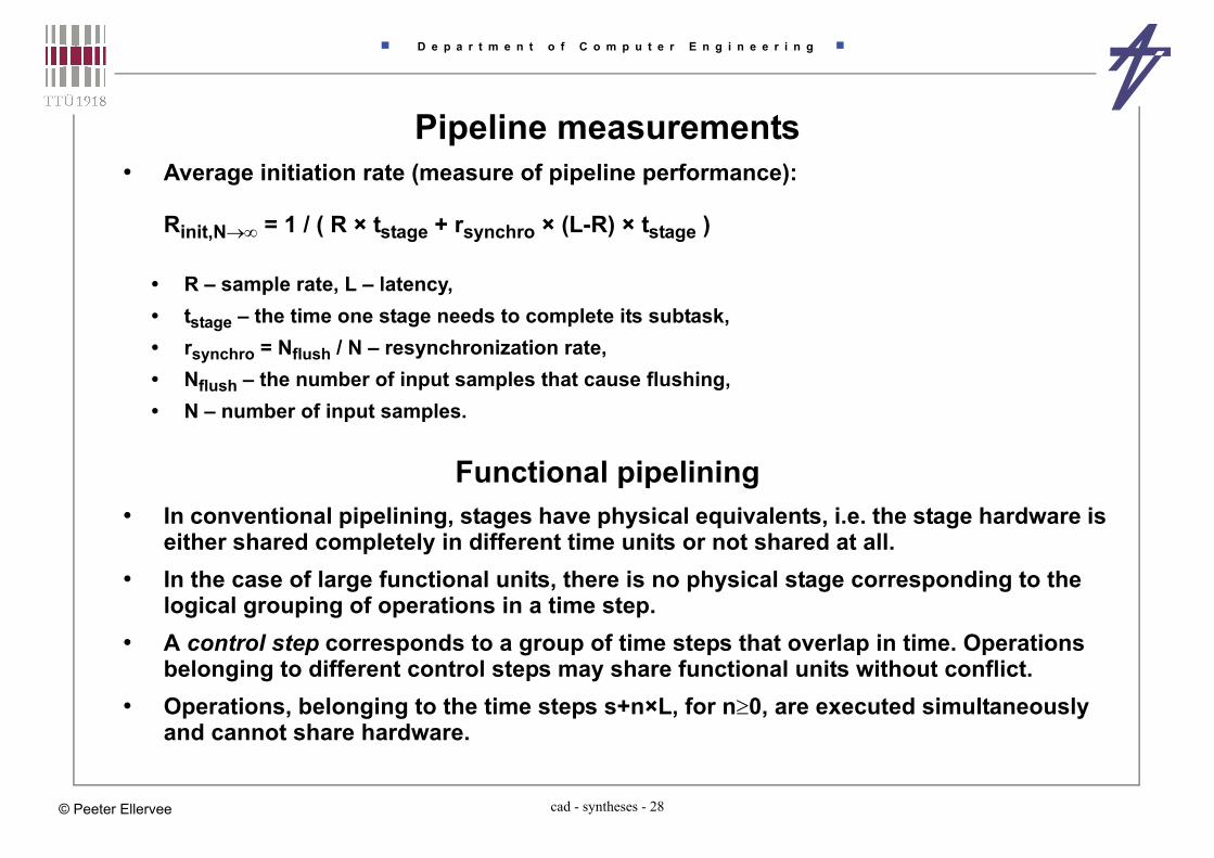
Pipeline measurements• Average initiation rate (measure of pipeline performance):
Rinit,N = 1 / ( R × tstage + rsynchro × (L-R) × tstage )
• R – sample rate, L – latency,• tstage – the time one stage needs to complete its subtask,• rsynchro = Nflush / N – resynchronization rate,• Nflush – the number of input samples that cause flushing,• N – number of input samples.
Functional pipelining• In conventional pipelining, stages have physical equivalents, i.e. the stage hardware is
either shared completely in different time units or not shared at all.• In the case of large functional units, there is no physical stage corresponding to the
logical grouping of operations in a time step.• A control step corresponds to a group of time steps that overlap in time. Operations
belonging to different control steps may share functional units without conflict.• Operations, belonging to the time steps s+n×L, for n0, are executed simultaneously
and cannot share hardware.

D e p a r t m e n t o f C o m p u t e r E n g i n e e r i n g
cad - syntheses - 29© Peeter Ellervee
Functional pipelining of 8-point FIR filter
**
*
*
+
Control step 1
+
++
+
+
+
Control step 2
1
2
3
4
5
6*
**
*
+
+
++
+
+
+1
2
3
4
5
6
**
*
*
+
+
++
+
+
+1
2
3
4
5
6

D e p a r t m e n t o f C o m p u t e r E n g i n e e r i n g
cad - syntheses - 30© Peeter Ellervee
Retiming• Minimization of the cycle-time or the area of synchronous circuits by changing the
position of the registers• cycle-time <- critical path
• The number of registers may increase or decrease• area minimization corresponds to minimizing the number of registers• combinational circuits are not affected (almost)
• Synchronous logic network• variables / boolean equations / synchronous delay annotation
Retiming at higher abstraction levels?• The same, in principle, as for logic networks
• operation nodes - functions / delay nodes - e.g. shared resources (memories)
• More possibilities to manipulate the functions -higher complexity of the optimization task
• partitioning/merging functions• reorganizing shared resources
D e p a r t m e n t o f C o m p u t e r E n g i n e e r i n g
cad - syntheses - 31© Peeter Ellervee
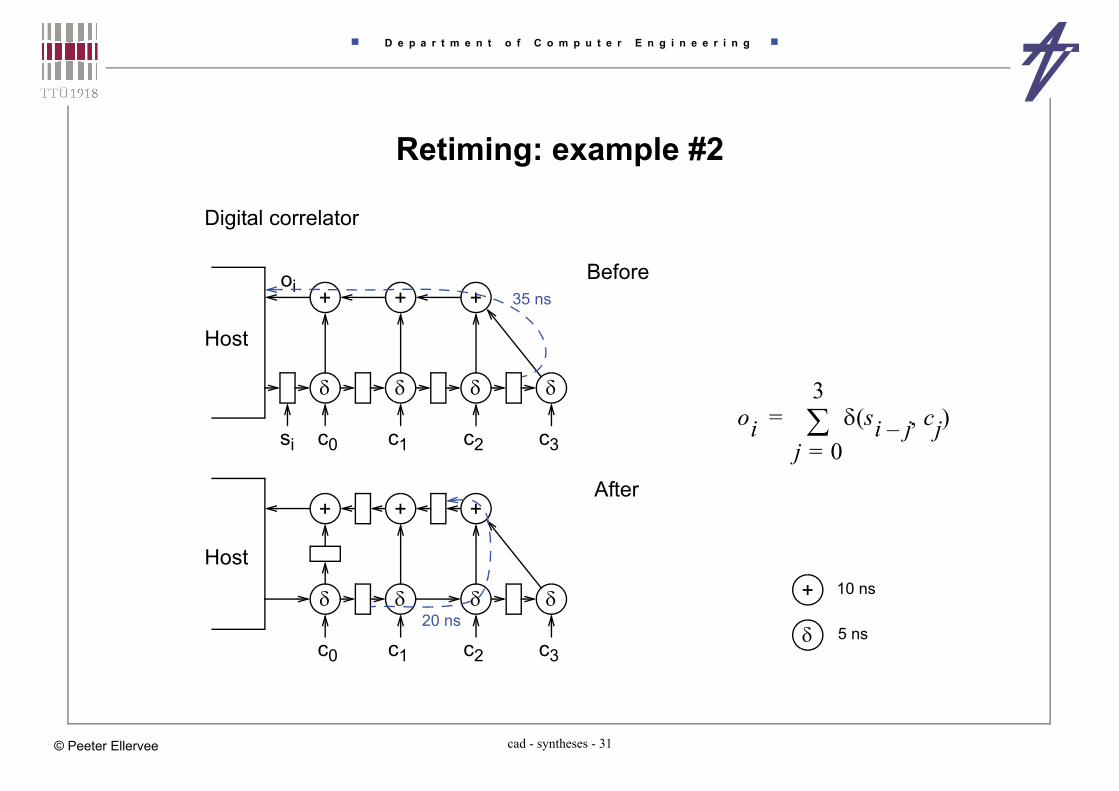
Retiming: example #2
Digital correlator
si c0 c1 c2 c3
+ + +oi
Host
35 ns
+ 10 ns
5 nsc0 c1 c2 c3
+ + +
Host
20 ns
Before
After
oi si j– cj( )j 0=
3=
D e p a r t m e n t o f C o m p u t e r E n g i n e e r i n g
cad - syntheses - 32© Peeter Ellervee
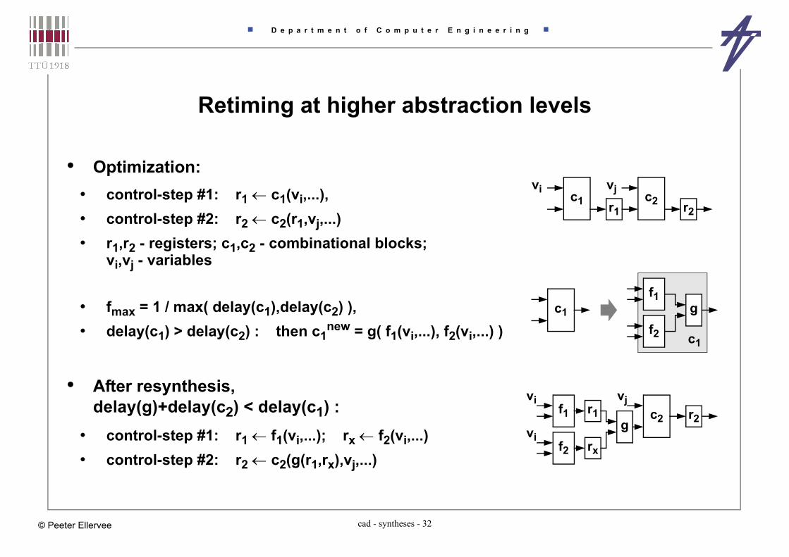
Retiming at higher abstraction levels
• Optimization:• control-step #1: r1 c1(vi,...), • control-step #2: r2 c2(r1,vj,...) • r1,r2 - registers; c1,c2 - combinational blocks;
vi,vj - variables
• fmax = 1 / max( delay(c1),delay(c2) ), • delay(c1) > delay(c2) : then c1
new = g( f1(vi,...), f2(vi,...) )
• After resynthesis, delay(g)+delay(c2) < delay(c1) :
• control-step #1: r1 f1(vi,...); rx f2(vi,...) • control-step #2: r2 c2(g(r1,rx),vj,...)
c1 c2r1
vi vj
r2
c2
rx
vi vjr2
c1
f1
c1
gf2
f1g
f2
r1
vi

D e p a r t m e n t o f C o m p u t e r E n g i n e e r i n g
cad - syntheses - 33© Peeter Ellervee
Transformations at System LevelMotivation
• Multimedia applications• MPEG 4 – > 2 GOP/s, > 6 GB/s, > 10 MB storage
• Embedded systems, SoC, NoC• Memory is a power bottleneck
• MPEG-2 decodes – logic 27%, i/o 24%, clock 24%, on-chip memory 25%• CPU + caches – logic 25%, i/o 3%, clock 26%, on-chip memory 46%
• Memory is a speed bottleneck [Patterson] • Moore’s Law – Proc 60%/year• DRAM – 7%/year• Processor-memory speed gap – 50%/year!
• High Performance Computing• CPU constrained vs Memory constrained
data in data out
PE1 PE2 PE3
M1 M2 M3
D e p a r t m e n t o f C o m p u t e r E n g i n e e r i n g
cad - syntheses - 34© Peeter Ellervee
What can be done?
• Reduce overheads!• do necessary calculations only
• do not duplicate calculations vs. do not store unnecessary data• data must have the right size (bitwidth, array size)
• select the right data layout• bitwidth can be reduced by coding• number of switchings on a bus can be reduced by coding
• exploit memory hierarchy• local copies may significantly reduce data transfer
• distribute load• systems are designed to stand the peak performance
• But do not forget trade-offs...

D e p a r t m e n t o f C o m p u t e r E n g i n e e r i n g
cad - syntheses - 35© Peeter Ellervee
Data layout optimization
• Input/output data range given• what about intermediate data?
• Integer vs. fixed point vs. floating point• integer
• + simple operations• - no fractions
• fixed point• + simple add/subtract operations• - normalization needed for multiplication/division
• floating point• + flexible range• - normalization needed
D e p a r t m e n t o f C o m p u t e r E n g i n e e r i n g
cad - syntheses - 36© Peeter Ellervee
Data layout optimizationSoftware implementations
• Example: 16-bit vs. 32-bit integers?• depends on the CPU, bus & memory architectures• depends on the compiler (optimizations)• 16-bit
• + less space in the main memory• + faster loading from the main memory into cache• - unpacking/packing may be needed (compiler & CPU depending)• - relative redundancy when accessing a random word
• 32-bit• + data matches the CPU word [“native” for most of the modern CPUs]• - waste of bandwidth (bus load!) for small data ranges
• The same applies 32 vs. 64-bit integers

D e p a r t m e n t o f C o m p u t e r E n g i n e e r i n g
cad - syntheses - 37© Peeter Ellervee
Data layout optimizationHardware implementations
• Example #1: 16-bit integer vs. 16-bit fixed point vs. 16-bit floating point• integer – 1+15 bits ~~ -32000 to +32000, precision 1• fixed point – 1+5+10 bits ~~ -32 to +32, precision ~0.001 (~0.03%)
• normalization == shifting
• floating point – 1+5+10 bits ~~ -64000 to +64000, precision ~0.1%• normalization == analysis + shifting
• Example #2: 2’s complement vs. integer with sign• 2’s complement – +1 == 00000001, 0 == 00000000, -1 == 11111111• integer + sign – +1 == 00000001, 0 == 00000000/10000000, -1 == 10000001• number of switchings when data swings around zero!!!! [e.g., DSP]
D e p a r t m e n t o f C o m p u t e r E n g i n e e r i n g
cad - syntheses - 38© Peeter Ellervee
Optimizing the number of calculations• Input space adaptive design – avoid unnecessary calculations
• input data is analyzed for boundary cases• boundary cases have simplified calculations (vs. the full algorithm)• “boundary case” – it may happen in the most of the time
• ... and the full algorithm is actually calculating nothing
• Trade-offs• extra hardware is introduced
• the algorithm is essentially duplicated (or triplicated or ...)• extra units for analysis are needed
• implementation is faster• less operations require less clock steps• operations themselves can be faster
• implementation consumes less power• a smaller number of units are involved in calculations• the clock frequency can be slowed• supply voltage can be lowered

D e p a r t m e n t o f C o m p u t e r E n g i n e e r i n g
cad - syntheses - 39© Peeter Ellervee
Input space adaptive design – The Case
• Discrete wavelet transformation • four input words – A, B, C, D• in 95.2% cases: A = B = C = D• four additions, four subtractions and
four shifts are replaced with four assignments
• Results• area: +17.5%• speed: 52.1% (cycles)• power: 58.9%
Vdd scaled: 26.6%
original behavior optimized behavior
i1 i2 i3in
o1 o3o2om
. . .
. . .
. .
. .
optimizedsub-behavior
i2 > i1
i1 i2 i3in
o1 o3o2om
. . .
. . .
. .
. .
f(i1,i2)
originalsub-behavior
f(i1,i2)
originalsub-behavior

D e p a r t m e n t o f C o m p u t e r E n g i n e e r i n g
cad - syntheses - 40© Peeter Ellervee
Input space adaptive designFew examples
• Multiplication with zero• result is zero –> nothing to calculate• two comparators, few blocking gates, plus some extras to the controller• multiplication with one, etc.• it must be cost efficient – the extra HW consumes power too!
• Multiplier size• A32*B32 = (AH16*216+AL16)*(BH16*216+BL16) = ...• ... = AH16*BH16*232+AH16*BL16*216+AL16*BH16*216+AL16*BL16 • A < 216 & B < 216 –> AH16=0 & BH16=0
• Multiplication with a constant –> shift-adds• 6*x = 4*x+2*x = (x<<2) + (x<<1)• - 1.75*x = 0.25*x - 2*x = (x>>2) - (x<<1)

D e p a r t m e n t o f C o m p u t e r E n g i n e e r i n g
cad - syntheses - 41© Peeter Ellervee
Memory architecture optimizationLife time of array elements
B = f(A);C = g(B);
A
B
C
typicalallocation
life times
a[i]==mem[i]b[i]==mem[base_b+i]c[i]==mem[base_c+i]
B
A
C
wasted
a smarterallocation
B
A C
a[i]==mem[i]b[i]==mem[base_b+i]c[i]==mem[i]
BA C
the smallestmemory waste
a[i]==mem[i]b[i]==mem[size-i]c[i]==mem[i]
Improved allocations

D e p a r t m e n t o f C o m p u t e r E n g i n e e r i n g
cad - syntheses - 42© Peeter Ellervee
Memory access – code transformations• Code transformations to reduce/balance data transfers
• Loop transformations• improve regularity of accesses• improve locality: production –> consumption• expected influence – reduce temporary and background storage
for (j=1; j<=M; j++)for (i=1; i<=N; i++)A[i]=foo(A[i],...);
for (i=1; i<=N; i++)out[i]=A[i];
storage size N
for (i=1; i<=N; i++) {for (j=1; j<=M; j++) {A[i]=foo(A[i],...);
}out[i]=A[i];
}
storage size 1

D e p a r t m e n t o f C o m p u t e r E n g i n e e r i n g
cad - syntheses - 43© Peeter Ellervee
Polyhedral model - polytope placementLife time analysis of array elements
• select the right indexing order• merge the loops• can be used for “loop pipelining” – possible index range expansion
j
i
for (i=1; i<=N; i++)for (j=N; j>=1; j--)A[i][j]=foo(A[i-1][j],...);
indexing order
The indexing order must preserve causality!
for (j=1; j<=N; j++)for (i=1; i<=N; i++)A[i][j]=foo(A[i-1][j],...);
Storage requirements – # of dependency lines
D e p a r t m e n t o f C o m p u t e r E n g i n e e r i n g
cad - syntheses - 44© Peeter Ellervee
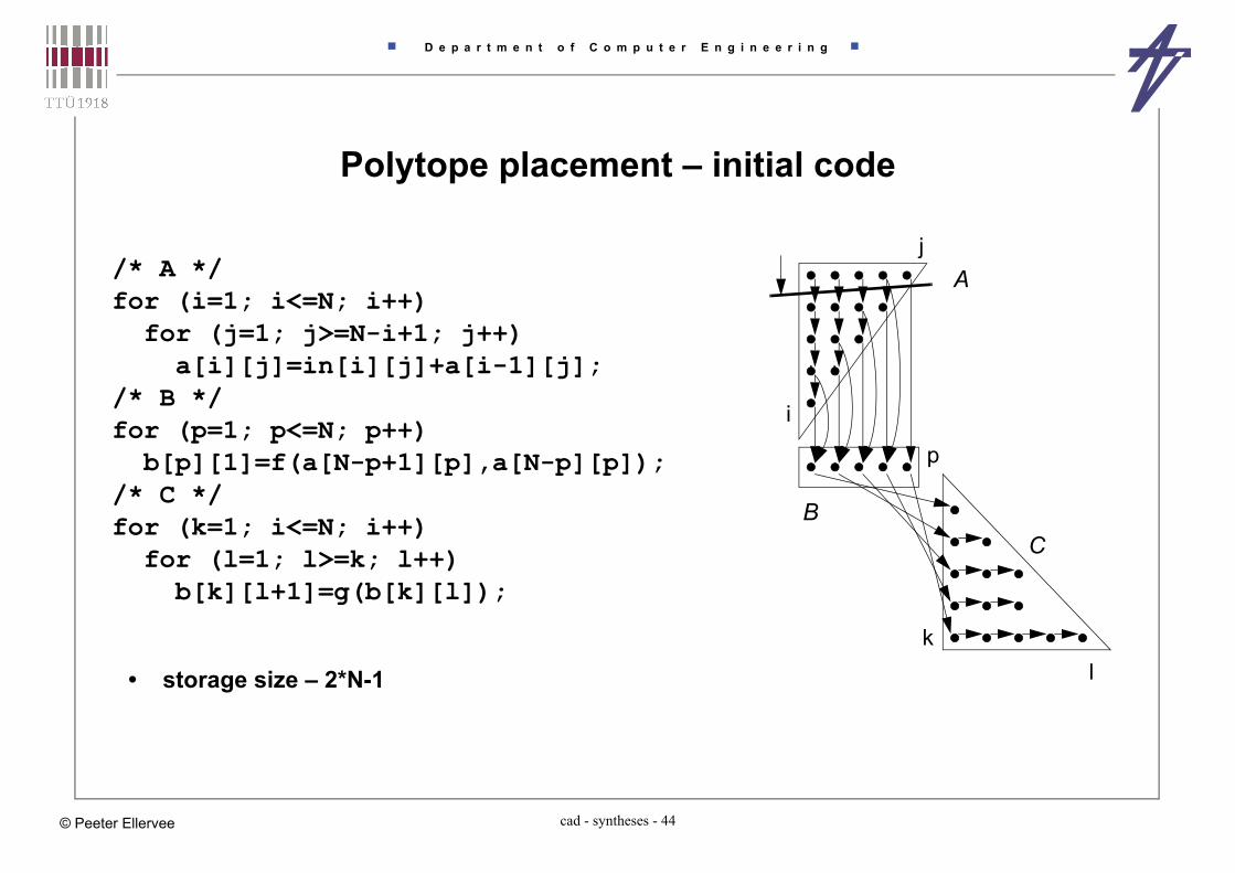
Polytope placement – initial code
j
i
p
kl
/* A */for (i=1; i<=N; i++)for (j=1; j>=N-i+1; j++)a[i][j]=in[i][j]+a[i-1][j];
/* B */for (p=1; p<=N; p++)b[p][1]=f(a[N-p+1][p],a[N-p][p]);
/* C */for (k=1; i<=N; i++)for (l=1; l>=k; l++)b[k][l+1]=g(b[k][l]);
A
BC
• storage size – 2*N-1

D e p a r t m e n t o f C o m p u t e r E n g i n e e r i n g
cad - syntheses - 45© Peeter Ellervee
Polytope placement – reordering + loop merging
• storage size – 2
j
i
(p)
l
(k)
for (j=1; j<=N; j++) {for (i=1; i>=N-j+1; i++)a[i][j]=in[i][j]+a[i-1][j];
b[j][1]=f(a[N-j+1][j],a[N-j][j]);for (l=1; l>=j; l++)b[j][l+1]=g(b[j][l]);
}

D e p a r t m e n t o f C o m p u t e r E n g i n e e r i n g
cad - syntheses - 46© Peeter Ellervee
Exploiting memory hierarchy
• Inter-array in-place mapping reduces the size of combined memories• source array is consumed while processing and can be replaced with the result
• Introducing local copies reduces accesses to the (main) memory• cost of the local memory should be smaller than the cost of reduced accesses
• Proper base addresses reduce cache penalties• direct mapped caches –
the same block may be used by two different arrays accessed in the same loop!
• All optimizations• ~60% of reduce in memory accesses• ~80% of reduce in total memory size• ~75% of reduce in cycle count

D e p a r t m e n t o f C o m p u t e r E n g i n e e r i n g
cad - syntheses - 47© Peeter Ellervee
Introducing local copies• Data copies to exploit memory hierarchy
Image processing
edge detectionblurring
etc.
imagei
j
window
no buffering –9 accesses per pixel
Extra copies should be analyzedfor efficiency – time & power
3 line buffers
3 accesses per pixel(in cache) –
9 pixels in register file –1 access per pixelin the main memory
in the buffer memory
D e p a r t m e n t o f C o m p u t e r E n g i n e e r i n g
cad - syntheses - 48© Peeter Ellervee
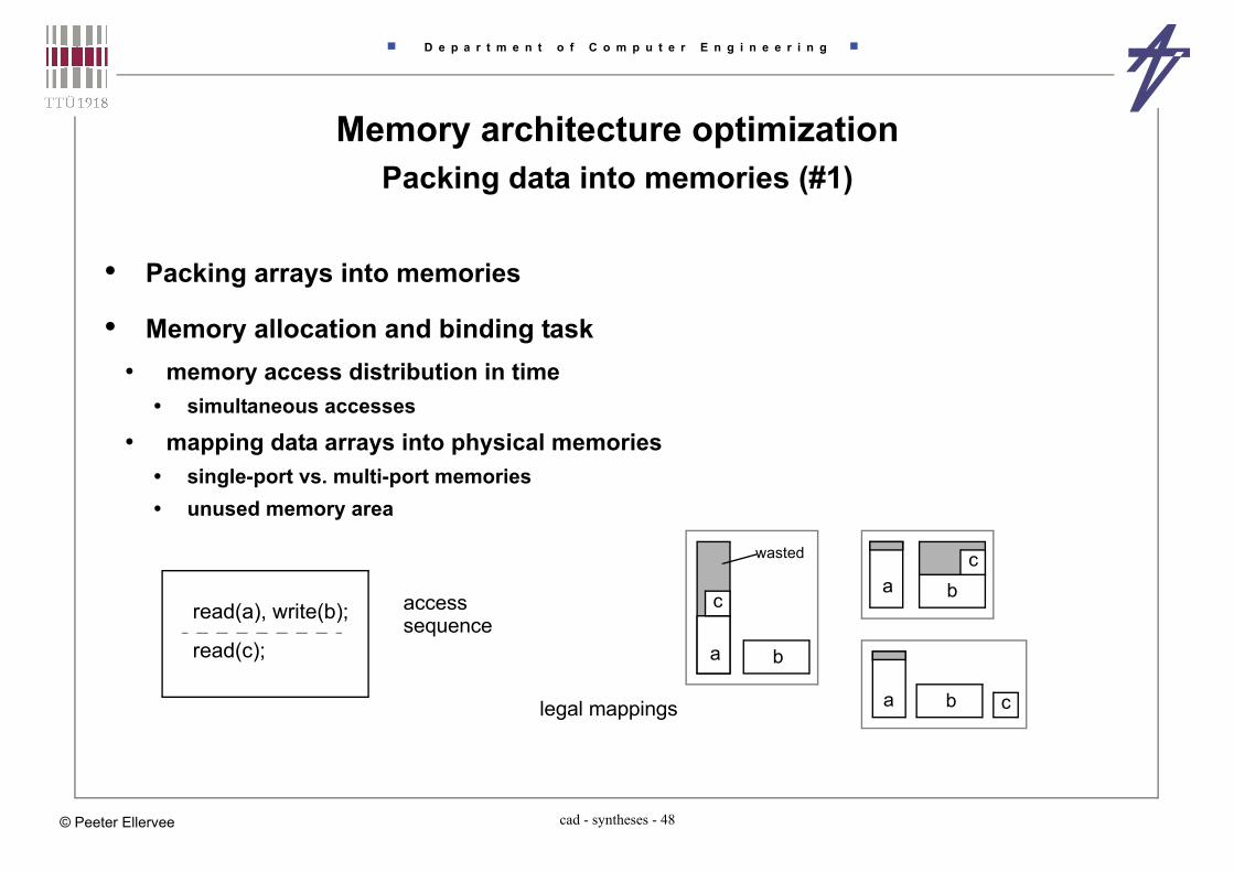
Memory architecture optimizationPacking data into memories (#1)
• Packing arrays into memories
• Memory allocation and binding task• memory access distribution in time
• simultaneous accesses
• mapping data arrays into physical memories• single-port vs. multi-port memories• unused memory area
a b c
a bc
b
c
a
legal mappings
read(a), write(b);
read(c);
access
wasted
sequence

D e p a r t m e n t o f C o m p u t e r E n g i n e e r i n g
cad - syntheses - 49© Peeter Ellervee
Packing data into memories (#2)Storage operation scheduling
• Usually scheduled together with other operations
• Affects memory architecture• number of memories• single-port versus multi-port memories
• Memory operations can be scheduled before others to explore possible memory architectures
• puts additional constraints for ordinary scheduling• distributes access more uniformly – reduces required bus bandwidth• reduces the number of possible combinations

D e p a r t m e n t o f C o m p u t e r E n g i n e e r i n g
cad - syntheses - 50© Peeter Ellervee
Storage operation scheduling
A A
B C
B D
C A
Accesses
A B
D C
Conflict Graph I n i t i a l
A
B
2
C
D
1
Allocation
A C
A B
B D
C A
Accesses
A B
D C
Conflict Graph After scheduling of
A
D
1
B
C
1
Allocation memory accesses

D e p a r t m e n t o f C o m p u t e r E n g i n e e r i n g
cad - syntheses - 51© Peeter Ellervee
Packing data into memories (#3)Packing data words (data fields) into memory words
• How to select candidates for packing?
example allocation bya compiler
separatememories
wasted
single memory combinedmapping
packed intoa single word
typedef struct {int field_0:3;int field_1:11;
} my_type;
my_type memo[256];my_type *p;
// ...p->filed_0 = 2;// ...
Case #1
memo
p->
Case #2
field_0
field_1
Case #3
field_0
field_1
Case #2 & Case #3
C
A
D
B
Case #4
field_0
field_1

D e p a r t m e n t o f C o m p u t e r E n g i n e e r i n g
cad - syntheses - 52© Peeter Ellervee
Packing data fields into memory words
• Data access duplications may occur• a word (field) is read but discarded• extra reads may be needed to avoid data corruption when writing
r(f1)c r(f1+f2)
read-after-read
w(f1)
w(f2)
w(f1+f2)
write-write
r(f2)
r(f1)
r(f2)
r(f1+f2)
read-read
r’(f1+f2)
w(f1+f2)
r(f1+f2)
single-write
r’(f1)a
w(f2)
a

D e p a r t m e n t o f C o m p u t e r E n g i n e e r i n g
cad - syntheses - 53© Peeter Ellervee
Address code optimization – loop-invariant code motion• Array access – base address, dimensions, repeated access patterns
• Address calculations that are repeated at every iteration
• Not handled by compilers - it’s out of basic block optimization
for (k=-4; k<3; k++)for (i=-4; i<3; i++)Ad[32*(8+k)+16+i]
for (k=-4; k<3; k++) {tmp_k = 272 + 32*k;for (i=-4; i<3; i++)Ad[tmp_k+i]
}
272+32*k+i
(3+, 1*) x 49 = 245
+ (1+) x 49 = 70
(1+, 1*) x 7 +

D e p a r t m e n t o f C o m p u t e r E n g i n e e r i n g
cad - syntheses - 54© Peeter Ellervee
Modulo operations
Counter base address generation units
• Customized hardware• special addressing units are cheaper• data-path itself gets simpler• essentially distributed controllers
for (i=0; i<=20; i++)addr = i % 3;
ptr = -1;for (i=0; i<=20; i++) {if (ptr>=2) ptr-=2;else ptr++;addr = ptr;
}

D e p a r t m e n t o f C o m p u t e r E n g i n e e r i n g
cad - syntheses - 55© Peeter Ellervee
Scheduling of high performance applications• Critical path – sequence of operations with the longest finishing time
• Critical path in clock steps vs critical path inside clock period (in time units)• Topological paths vs. false paths
• Latency ~ clock_period * critical_path_in_clock_steps
• Loop folding and pipelining• Folding – fixed number of cycles
• no need to calculate conditions in loop header, iterations of the loop body can overlap
• Pipelining – executing some iterations of the loop body in parallel (no dependencies!)
• Speculative execution / Out of order execution• Execution of operations in a branch can be started before the branch itself starts• Extra resources required• Speeding up the algorithm – guaranteed speed-up vs overall speed-up (statistical)• Scheduling outside basic blocks – “flattening” hierarchy
• increase in the optimization complexity
D e p a r t m e n t o f C o m p u t e r E n g i n e e r i n g
cad - syntheses - 56© Peeter Ellervee
Conclusion
• Efficient implementation is not only the hardware optimization
• Efficient implementation is• selecting the right algorithm• selecting the right data types• selecting the right architecture• making the right modifications• and optimizing...
• right == the most suitable
• Think first, implement later!


![Modeling Abstraction Hierarchy Levels of the Cyber Attacks ... · Abstraction Hierarchy is made of five abstraction levels [3] [8]: S5 General purposes: comprehended at the highest](https://img.dokumen.tips/doc/110x75/5f5ae2ac75d17c1b1a79a9c8/modeling-abstraction-hierarchy-levels-of-the-cyber-attacks-abstraction-hierarchy.jpg)