Embed Size (px)
Citation preview

1
Syngas production by catalytic partial oxidation of methane over (La0.7A0.3)BO3 (A=Ba, Ca, Mg, Sr, and B = Cr or Fe) perovskite oxides
for portable fuel cell applications
Ma Su Su Khine a,b, Luwei Chena,*, Sam Zhangc, Jianyi Lina,
San Ping Jiang d,*
a Institute of Chemical and Engineering Sciences, 1 Pesek Road, Jurong Island, Singapore
627833
b Department of Chemical System Engineering, School of Engineering, The University of
Tokyo, Tokyo, 113-8656 Japan
c School of Mechanical and Aerospace Engineering, Nanyang Technological University,
Singapore 639798
d Fuels and Energy Technology Institute & Department of Chemical Engineering, Curtin
University, Perth, WA 6102, Australia
* Corresponding authors. E-mail addresses: [email protected] (L. Chen); [email protected]
(SP Jiang)

2
Abstract
Hydrogen is a clean energy carrier for future. More efficient, economic and small-scale
syngas production has therefore important implications not only on the future sustainable
hydrogen-based economy but also on the distributed energy generation technologies such
as fuel cells. In this paper, a new concept for syngas production is presented with the use
of redox stable lanthanum chromite and lanthanum ferrite perovskites with A-site doping
of Ba, Ca, Mg and Sr as the pure atomic oxygen source for the catalytic partial oxidation
of methane. In this process, catalytic partial oxidation reaction of methane occurs with the
lattice oxygen of perovskites, forming H2 and CO syngas. The oxygen vacancies due to
the release of lattice oxygen ions are regenerated by passing air over the reduced
nonstoichiometric perovskites. Studies by XRD, temperature-programmed reduction
(TPR) and activity measurements showed the enhanced effects of alkaline element A-site
dopants on reaction activity of both LaCrO3 and LaFeO3 oxides. In both series, Sr and Ca
doping promotes significantly the activity towards the syngas production most likely due
to the significantly increased mobility of the oxygen ions in perovskite oxide structures.
The active oxygen species and performance of the LaACrO3 and LaAFeO3 perovskite
oxides with respect to the catalytic partial oxidation of methane are discussed.
Keywords: Syngas; catalytic partial oxidation; Lanthanum chromite and ferrite
perovskite; lattice oxygen; fuel cells.

3
1. Introduction
Low cost production of hydrogen as a clean fuel is receiving increasing attention
under the background of the resources depletion and the high price of petroleum oil [1]. A
transition from fossil fuels to hydrogen and fuel cell technology in the next 50 years could
diversify energy source, increase national security, and reduce environmental pollution
and greenhouse gas emission. Under such situation, H2 will then be produced not only in
large scale in industrial areas, but also in fueling stations and customers’ on-site
applications in distributed scale[1, 2]. Current commercial production of H2 from natural
gas involves primarily either steam methane reforming (SMR) or catalytic partial
oxidation (CPO) [3, 4]. Catalytically converting methane to syngas is a significant route
for methane utilization, since syngas could be used to produce hydrogen or generate
electricity in fuel cells [5, 6]. There are three ways of converting methane to syngas,
including the steam reforming of methane (SRM) [3, 74], the carbon dioxide reforming of
methane (CRM) [85] and the catalytic partial oxidation of methane (CPO) [46]. Current
commercial H2 production is based on SMR technology, an energy intensive and high
CO2 emission process. Particularly, CPO has become the focus of researches in recent
years due to its obvious advantages, such as high energy efficiency, suitable CO/H2 ratio
for methanol synthesis and Fischer–Tropsch processes [7-9]. However, pure O2 via
conventional, cryogenic separation of air is a major expensive capital investment for CPO-
based syngas and hydrogen production, and it becomes increasingly expensive as unit size
is scaled down. In general, these technologies, though highly optimized over years of
development, remain probably too expensive and thus are not applicable for small-scale
production of syngas for portable fuel cells.
4
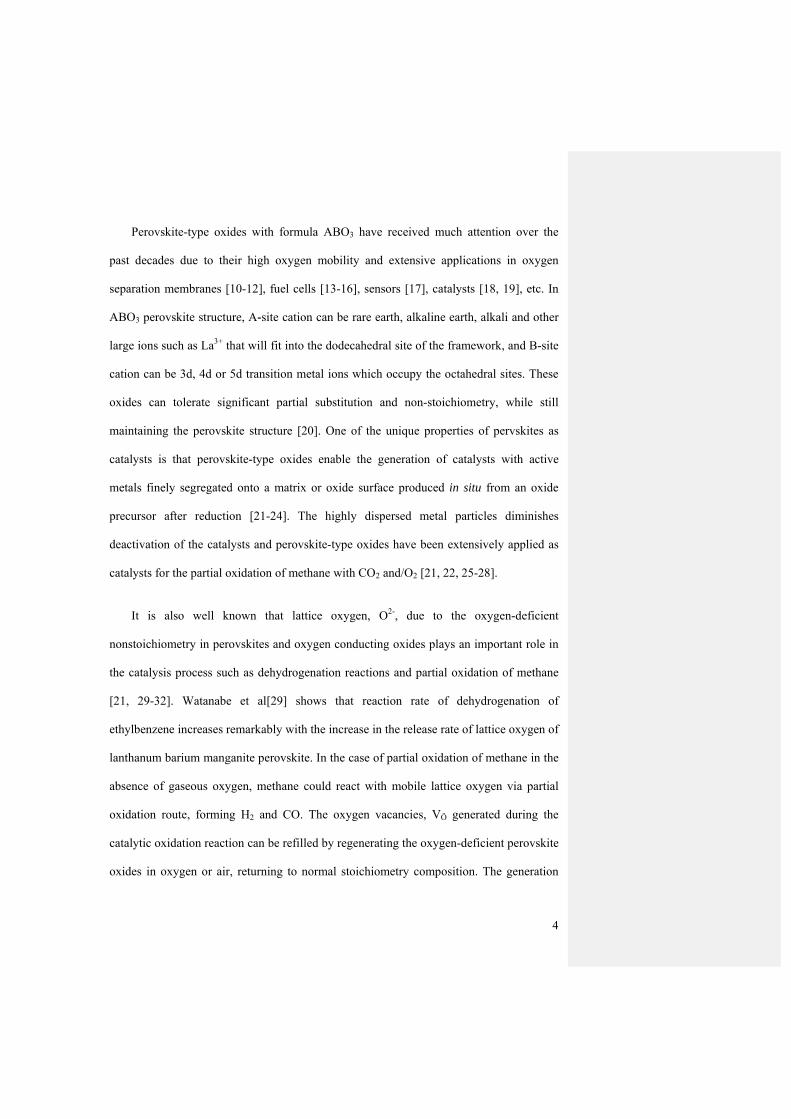
Perovskite-type oxides with formula ABO3 have received much attention over the
past decades due to their high oxygen mobility and extensive applications in oxygen
separation membranes [10-12], fuel cells [13-16], sensors [17], catalysts [18, 19], etc. In
ABO3 perovskite structure, A-site cation can be rare earth, alkaline earth, alkali and other
large ions such as La3+ that will fit into the dodecahedral site of the framework, and B-site
cation can be 3d, 4d or 5d transition metal ions which occupy the octahedral sites. These
oxides can tolerate significant partial substitution and non-stoichiometry, while still
maintaining the perovskite structure [20]. One of the unique properties of pervskites as
catalysts is that perovskite-type oxides enable the generation of catalysts with active
metals finely segregated onto a matrix or oxide surface produced in situ from an oxide
precursor after reduction [21-24]. The highly dispersed metal particles diminishes
deactivation of the catalysts and perovskite-type oxides have been extensively applied as
catalysts for the partial oxidation of methane with CO2 and/O2 [21, 22, 25-28].
It is also well known that lattice oxygen, O2-, due to the oxygen-deficient
nonstoichiometry in perovskites and oxygen conducting oxides plays an important role in
the catalysis process such as dehydrogenation reactions and partial oxidation of methane
[21, 29-32]. Watanabe et al[29] shows that reaction rate of dehydrogenation of
ethylbenzene increases remarkably with the increase in the release rate of lattice oxygen of
lanthanum barium manganite perovskite. In the case of partial oxidation of methane in the
absence of gaseous oxygen, methane could react with mobile lattice oxygen via partial
oxidation route, forming H2 and CO. The oxygen vacancies, VÖ generated during the
catalytic oxidation reaction can be refilled by regenerating the oxygen-deficient perovskite
oxides in oxygen or air, returning to normal stoichiometry composition. The generation

5
and re-generation steps continue, forming a cyclic operation to directly convert methane to
syngas as shown below.
In generation step: CH4 + ABO3 → CO + 2H2 + ABO3- (1)
In re-generation step: ABO3- + O2/N2 (air) → ABO3 + O2/N2 (air) (2)
Overall reaction: CH4 + ABO3→ CO + 2H2 + ABO3- (3)
The syngas production and regeneration steps with redox stable ABO3 perovskites as
atomic oxygen source are schematically shown in Figure 1.
The proposed process as described here is simple and also low cost because the
process does not require pure O2 as oxidants and is reversible due to the high structural
stability of perovskite oxides. Since the oxidation reaction occurs between CH4 and lattice
oxygen, O2- there is no risk of explosion which may be caused by mixtures of CH4 and
gaseous pure O2. The selectivity of CO and H2 would be expected to be higher than
conventional CPO process since further oxidation of CO and H2 (e.g., to CO2 and H2O) is
limited due to the fact that there is no presence of gaseous oxygen.
To demonstrate the feasibility of the process, we selected lanthanum chromite and
lanthanum ferrite perovskite oxides, (La1-xAx)CrO3 and (La1-xAx)FeO3 where A = Ba, Ca,
Mg and Sr as oxygen source for the partial oxidation of methane for the syngas production.
LaCrO3 and LaFeO3 are orthorhombic derivatives of the perovskite structure and exhibit
high structural stability, oxygen ion conductivity and high catalytic activity for the
application of interconnect and cathodes of solid oxide fuel cells [33-37]. It has been well

6
known that the catalytic activity and ionic conductivity of perovskite oxides can also be
improved by partial substitution on A- and/ or B-sites [16, 38, 39].
2. Experimental
2.1 Synthesis of perovskite-typed oxides
Lanthanum oxide and the alkaline earth metal oxide, all of which were analytical
reagent grade with purity > 99%, were used as initial materials for preparation of the (La1-
xAx)BO3 powders (A= Ba, Ca, Mg and Sr and B=Cr or Fe). The A-site substitution was 30
mol% for Mg, Ca and Ba and 25 mol % for Sr. The perovskite oxides were synthesized by
solid-state reaction process, and the oxides with stoichiometric ratios were mixed by
grinding and ball-milling in isopropanol for 5 hours, followed by calcination at 1200 C
for 5 h in air.
2.2 Material characterizations
Phase identification and crystal structures were investigated by x-ray powder
diffraction (XRD, Philips 1710), with a Cu-Kα radiation and a Ni filter, in the range of 2
= 15–85. Specific surface area of the as-prepared perovskite oxide powders were
determined by Brunauer, Emmett and Teller (BET) single point method over a
QUANTACHROME Autosorb-6 instrument. Prior to analysis, the samples were degassed
under vacuum, overnight. About 0.1 – 0.2 g of sample was used for each measurement.
The changes in the oxygen deficiency of oxide samples were measured by temperature-
programmed H2 reduction (TPR), performed on Thermo TPD/RO 1100 Catalyst Analyzer
System. A perovskite oxide sample of 50 mg was placed in a quartz micro-reactor and a

7
5% H2/95% argon gas mixture with a flow rate of 50 ml/min was used as the reducing gas.
The temperature was raised at a constant rate of 10 C/min from 50 to 900 C and
maintained for 10 minutes before the test. Prior to the TPR testing the powder samples
were pretreated at 300 C for 30 min in air.
2.3 Measurement
Partial oxidation of methane over peroviskites was studied by two experimental
techniques, i.e., temperature-programmed surface reaction (TPSR) and steady state
reaction (SSR) at 850 oC. The experimental setup is shown in Fig.2. For TPSR, 100 mg of
the oxide sample was packed in a quartz tube micro-reactor ( = 4 mm), between layers
of quartz wool. The sample was heated in the stream of 5 vol% CH4 in Ar gas at a
constant rate of 10 C/min from room temperature to 950 C. The effluent gas was
analyzed on-line by mass spectroscopy (MS, Hiden HPR – 20 QIC). The reacted sample
powders were then regenerated at 950 oC in 5% O2/Ar at a flow rate of 50 mLml/min with
no change in the set up conditions.
Steady state reaction (SSR) was carried out in a continuous-flow fixed bed quartz
micro-reactor (inner diameter = 10.3 mm, outer diameter = 12.0 mm) at atmospheric
pressure packed with 250 mg samples that were sieved to a grain size of 180/300 m. The
use of large quartz tube in this case is due to the increased catalyst loading. The sample
temperature was raised at a constant rate of 10 °C/min from 50 to 850 °C in the flow of Ar
and hold at 850 oC. A gas mixture of 5% methane in argon (carrier gas) with a total flow
rate of 100 ml/min was passed through the sample in the quartz tube. The reaction
products were detected by an online gas chromatography on a Shimadzu GC-2010

8
equipped with both a thermal conductivity detector (for H2, CO, CH4, CO2 and N2) and a
flame ionizing detector (for CxHy and other products). Ar was used as the internal
standard.
The conversion of CH4, XCH4 is defined as follows:
%1004
4
44
in
outin
CH
CHCH
CH mol
molmolX (4)
3. Results and discussions
3.1 BET and XRD
Table 1 lists the composition and BET surface area for the as-prepared (La1-xAx)CrO3
and (La1-xAx)FeO3 perovskite samples. Due to the high calcination temperatures used in
the sample preparation, the surface areas of the samples are generally low (≤ 5 m2/g).
Among the oxides used, the lanthanum ferrite series have a higher surface area than that of
chromite series.
Figure 3 displays the X-ray diffraction patterns of LaCrO3 and LaFeO3 in the forms of
as-prepared after the catalytic oxidation (i.e., generation reaction (1)) and the regeneration
reaction (2)). The as-prepared LaCrO3 and LaFeO3 show typical well-crystallized
perovskite structures, indicating the successful synthesis of the LaCrO3 and LaFeO3
perovskite structure by the solid-state reaction method. After partial oxidation reaction in
5% CH4 (Ar balanced) at 900 oC, traces of La2O3, La(CrO3) and La(CrO4) were observed
in addition to LaCrO3 perovskite main phase (Fig.3a), indicating minor or partial
decomposition of LaCrO3. However, after regeneration in 5%O2/Ar at 950 oC, the XRD

9
peaks associated with La2O3, La(CrO3) and La(CrO4) disappear completely and only the
peaks for perovskite oxides remain, showing that the perovskite structure can be
completely recovered after the regeneration in oxygen. This indicates that structural
change during the catalytic oxidation of methane is reversible. In the case of LaFeO3 there
is no change in the perovskite-type structure after the catalytic oxidation in
5%CH4/95%Ar at 950oC (Fig.3b). This indicates that LaFeO3 is quite stable for the
catalytic oxidation in methane.
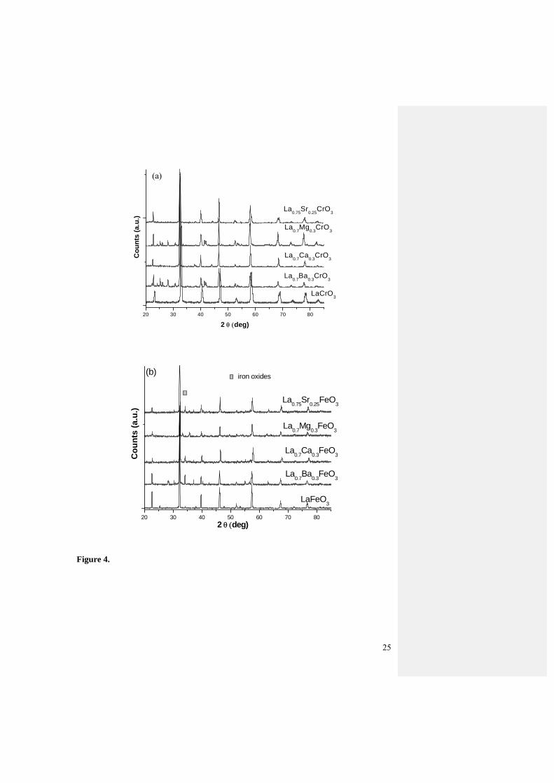
Figure 4 is the XRD patterns of the as-prepared doped LaCrO3 and LaFeO3 oxide
series. Secondary phase of La2O3 was found in Ba and Mg doped LaCrO3 (Fig.4a),
probably due to the large size of the Ba and Mg dopants. In the case of Ca and Sr-doped
LaCrO3, no secondary phases were found although a small shift to larger diffraction angle
is observable for La0.75Sr0.25CrO3 (Fig.4a), indicating the lattice distortion due to Sr
substitution. Sr2+ ion is slightly larger than La3+ ion in size (0.144 vs. 0.136 nm). For the
doped LaFeO3 oxide series, Fe2O3 phase is observed in all doped samples, while Fe2O3
phase appears to be higher in the Sr and Ba doped samples (Fig.4b). Similar to Ba-doped
LaCrO3, secondary phases were also observed in Ba-doped LaFeO3. Nonetheless, the
peaks associated with perovskite oxides were dominant in all the XRD patterns, indicating
the formation of main perovskite phases.
3.2. TPR
Temperature-programmed reduction (TPR) was carried out to study the oxygen
mobility and the amount of oxygen which can be released from the oxides via the reaction
with hydrogen. Figure 5 shows the TPR profiles of the amount of consumed hydrogen
versus reaction temperature for the doped LaCrO3 and LaFeO3 oxide series. The amount
of H2 consumed per mole of the oxide sample can be obtained from calibrated integrated
10
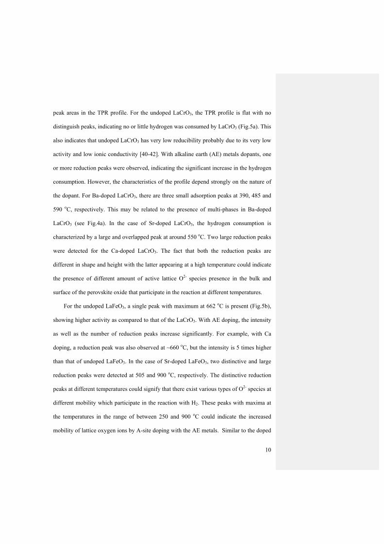
peak areas in the TPR profile. For the undoped LaCrO3, the TPR profile is flat with no
distinguish peaks, indicating no or little hydrogen was consumed by LaCrO3 (Fig.5a). This
also indicates that undoped LaCrO3 has very low reducibility probably due to its very low
activity and low ionic conductivity [40-42]. With alkaline earth (AE) metals dopants, one
or more reduction peaks were observed, indicating the significant increase in the hydrogen
consumption. However, the characteristics of the profile depend strongly on the nature of
the dopant. For Ba-doped LaCrO3, there are three small adsorption peaks at 390, 485 and
590 oC, respectively. This may be related to the presence of multi-phases in Ba-doped
LaCrO3 (see Fig.4a). In the case of Sr-doped LaCrO3, the hydrogen consumption is
characterized by a large and overlapped peak at around 550 oC. Two large reduction peaks
were detected for the Ca-doped LaCrO3. The fact that both the reduction peaks are
different in shape and height with the latter appearing at a high temperature could indicate
the presence of different amount of active lattice O2- species presence in the bulk and
surface of the perovskite oxide that participate in the reaction at different temperatures.
For the undoped LaFeO3, a single peak with maximum at 662 oC is present (Fig.5b),
showing higher activity as compared to that of the LaCrO3. With AE doping, the intensity
as well as the number of reduction peaks increase significantly. For example, with Ca
doping, a reduction peak was also observed at ~660 oC, but the intensity is 5 times higher
than that of undoped LaFeO3. In the case of Sr-doped LaFeO3, two distinctive and large
reduction peaks were detected at 505 and 900 oC, respectively. The distinctive reduction
peaks at different temperatures could signify that there exist various types of O2- species at
different mobility which participate in the reaction with H2. These peaks with maxima at
the temperatures in the range of between 250 and 900 oC could indicate the increased
mobility of lattice oxygen ions by A-site doping with the AE metals. Similar to the doped

11
LaCrO3 series, A-site doping changes significantly the TPR profile of LaFeO3 samples.
Although the TPR curves of the LaCrO3 series have different profile as compared to that
of LaFeO3 series, it can be seen that in general, Sr and Ca doping promotes significantly
the reducibility of perovskites, most likely due to the significantly increased mobility of
the lattice oxygen ions in perovskite oxide structures.
The total amount of hydrogen consumed per mole of catalysts during TPR was
calculated and the results are given in Table 2. The ratios of moles of hydrogen
consumption per mole of catalysts indicate the variations in the availability or mobility of
the oxygen lattice ions within the oxides. A high consumption implies the high availability
of lattice oxygen, O2- for the catalytic partial oxidation of methane (reaction (1)). The
amount of hydrogen required for the reduction of one mole of catalyst is much lower for
the LaCrO3 series as compared to the LaFeO3 series. The results are justifiable as LaFeO3
is more readily reducible than the LaCrO3[20]. In comparison, the undoped LaCrO3 and
LaFeO3 have the smallest moles of H2 consumed by one mole of catalysts, 0.08 and 0.12,
respectively which suggested that both oxides have the least amount of lattice oxygen
reacted. AE doping on A-site of ABO3 peroviskite greatly enhanced the oxygen
availability. As it can be seen from Table 2, the amount of H2 consumed by AE-doped
LaCrO3 and LaFeO3 is one order of magnitude larger than their undoped counterparts.
Among all the samples, the highest values obtained under each series are by the
(La0.7Ca0.3)CrO3 and (La0.75Sr0.25)FeO3, which indicate that both (La0.7Ca0.3)CrO3 and
(La0.75Sr0.25)FeO3 possesses the highest amount of active oxygen species that could be
utilized for the catalytic oxidation of methane.
3.3. Catalytic partial oxidation of CH4

12
Figure 6 shows the mass spectroscopy plots of the hydrogen production as a function
of temperature when the peroviskite oxides were exposed to 5%CH4 in Ar from room
temperature to 950 °C. Since small amount of perovisite oxides were used, 5% CH4 was
more than enough to react with the lattice oxygen.
For undoped LaCrO3, hydrogen production starts at ~800 oC and AE doping shifts the
hydrogen formation temperature to lower temperatures and increases the hydrogen
intensity (Fig.6a). Most of the H2 peaks appear at temperatures from 820 to 900 °C for the
doped LaCrO3 oxides series with (La0.75Sr0.25)CrO3 having the highest intensity. In the
case of Mg and Sr doped LaCrO3, hydrogen production started at 750 oC and reached the
maximum at ~820 oC. Ca-doped LaCrO3 oxide gave two hydrogen formation peaks at 840
and 900 oC, respectively. This observation is consistent with the TPR result in Fig. 5a and
could be due to the fact that different oxygen species in the Ca-doped LaCrO3 sample is
evolved at different temperature. Undoped LaFeO3 also starts the hydrogen formation at
~800 oC but the intensity of the hydrogen formation is weak (Fig.6b), similar to that of
undoped LaCrO3. This indicates that both undoped LaCrO3 and LaFeO3 are very stable
oxides with low activity for hydrogen production since the available oxygen for reaction is
very limited as shown in Table 2. With the addition of AE metal dopants, the minimum
temperatures needed for the partial oxidation of methane to syngas are reduced. Similar to
the doped LaCrO3 series, Sr-doped LaFeO3 has the highest H2 intensity at 853 oC. The
increment in H2 production and methane activation ability of perovsites are correlated to
the oxygen mobility and availability as shown in Fig.5 and Table 2.
By using gas chromatography for on-line outlet gas analysis, as defined by Eq.(4), the
amount of CH4 converted was calculated and the syngas concentration in the outlet gas
stream was measured for both doped LaCrO3 and LaFeO3 oxide series at 850 oC in the 5%
Formatted: Font: Times New Roman
Formatted: Subscript

13
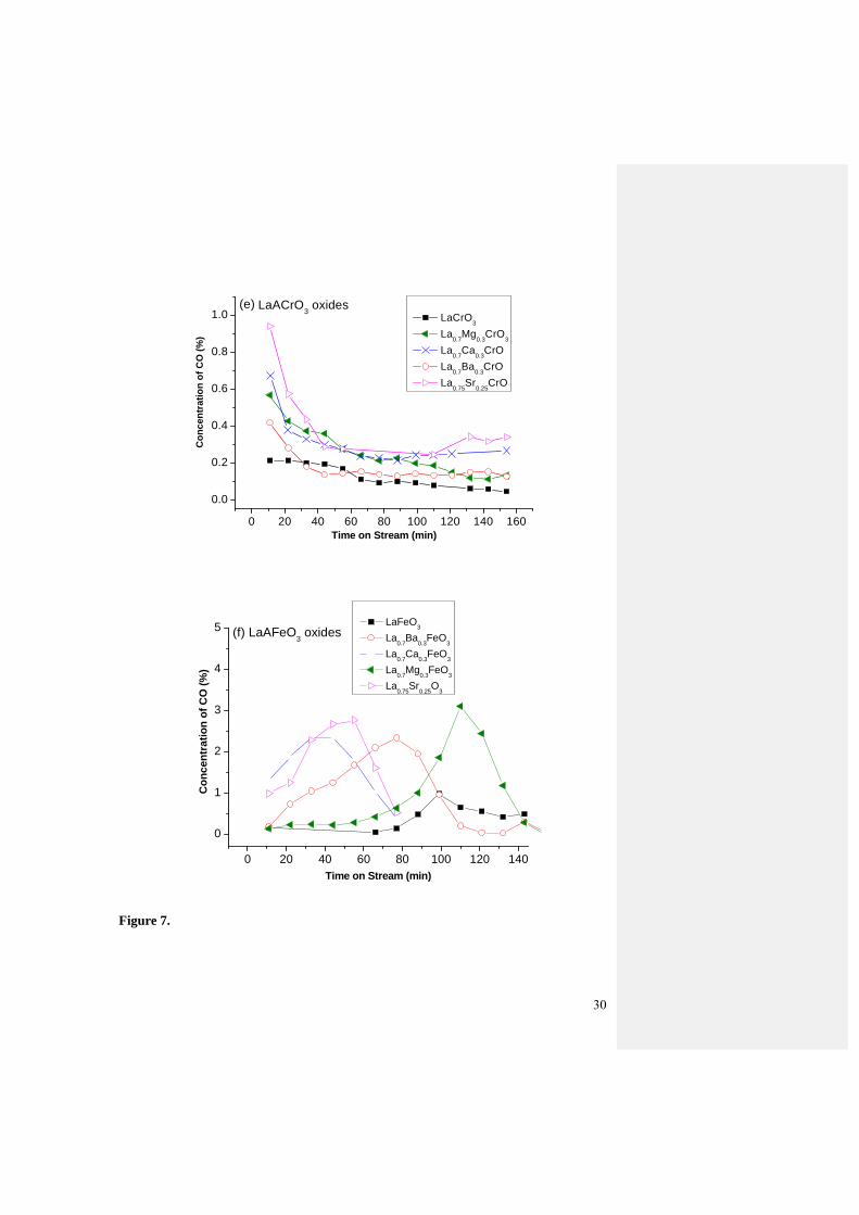
CH4-95%Ar gas stream with GHSV of 750 h-1. The results are shown in Fig.7. As seen in
Fig. 7a, the CH4 conversion on the doped LaCrO3 oxide series is relatively low (<12%)
and decreases gradually with the reaction time. The undoped LaCrO3 oxide yields the
lowest value of ~5% while the highest CH4 conversion is 12% produced by Sr doped
LaCrO3. Though the CH4 conversion decays at the first 70 mins, the highest conversion at
the end of the test at 130 min was observed on Sr-doped LaCrO3, 8% methane conversion.
The La0.7Ca0.3CrO3 oxide displays steady CH4 conversion of 10% in the first 80 min, after
which it drops rather quickly to 4%. The continuous decrease in the methane conversion
rate indicates that the activity of doped LaCrO3 decreases with the contact time with
methane, most likely due to the gradual reduction in the amount of lattice oxygen
available for the catalytic oxidation reaction.
Doped LaFeO3 oxides have a much higher CH4 conversion rate as compared to that of
doped LaCrO3 oxides counterpart. Also, very different from the continuous delay in
methane conversion in the case of doped LaCrO3, the activity of doped LaFeO3 exhibits a
significant induction period before reaching the maximum conversion rate (Fig.7b). For
undoped LaFeO3, the maximum conversion rate was 10% after reaction in 5%CH4/Ar for
90 min. Doping LaFeO3 with AE elements significantly shortens the induction period for
the catalytic oxidation reaction as well as enhances the activity. In the case of Sr doped
LaFeO3 the maximum conversion rate of 60% occurs at 65 min and the best activity and
performance was observed for the Ca doped LaFeO3, 70% conversion at ~30 min. For Mg
doped LaFeO3 it took ~120 mins to reach a maximum conversion rate of 65%.
The production rate of hydrogen and CO on doped LaCrO3 and LaFeO3 oxides
basically follows that of methane conversion (see Fig.7c-f). As illustrated in Fig. 7c, the
H2 concentration for undoped LaCrO3 and Ba-doped LaCrO3 are basically constant at 0.5

14
and 0.8% correspondingly. Sr doped LaCrO3 produces 2.4% of H2 and decreased to a
steady value of 1.0% after reacted for 80 min. The Ca dopant shows rather high yield of
H2 production, which decreases gradually from 2.25% to 1.5% in the first 60 min on
stream, and then remains steadily at the 1.5% in the next 80 min. Mg dopant displays
comparable trend, decreasing from 2.25% to 1.0%. Similar trend was also observed for the
CO concentration on doped LaCrO3 oxide series (Fig.7e).
Doped LaFeO3 oxides show increasing patterns for the H2 production with reaction
time (Fig. 7d). For LaFeO3 the H2 production increases to 2% after reaction for 90 min
after which remains at that value over the holding time of 140 min. The Sr doped oxide
displays rather a steady increasing H2 production in the first 60 min, reaches a maximum
of 10% and maintains for another 10 min, followed by continuous decline to 1%. The Ba
dopant follow similar trend with a gradual increase to 7%, and decreases to 1% in the next
80 min holding time. The La0.7Ca0.3CrO3 increases from initial value of 3% to 9% in the
60 min stream on line time. The Mg dopant takes a longer time to be activated to give a
raise from 0 to 11% in the 120th min. Similar trend was also observed for the CO
production (Fig.7f).
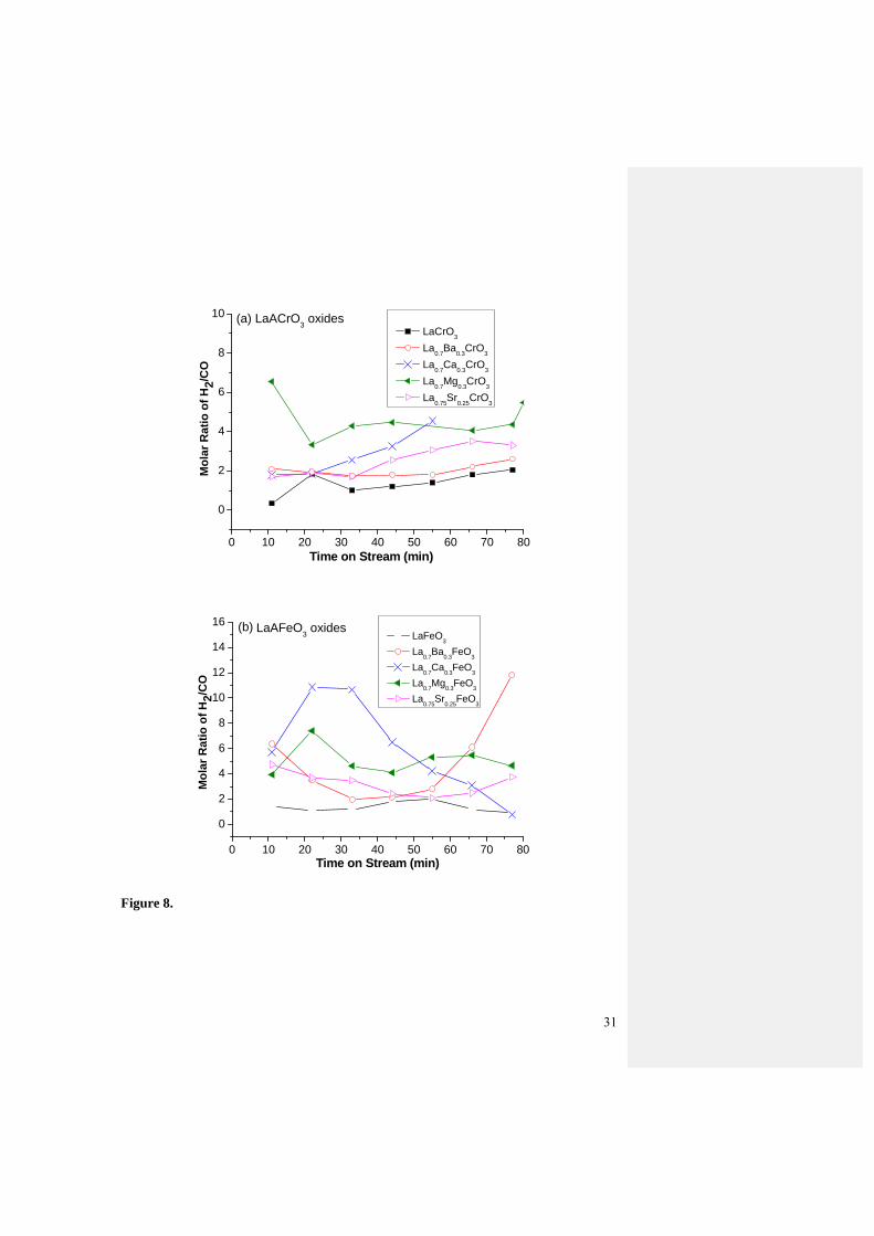
Fig.8 is the molar ratio of H2 to CO for both oxide series. The data were taken from
Fig.7c to Fig.7f. The H2 to CO molar ratio for the undoped LaCrO3 and LaFeO3 samples is
approximate 2 which is the theoretical value derived from partial oxidation of methane,
according to reaction (3). Doping generally enhances H2/CO ratio. LaMgCrO3, LaSrCrO3,
LaMgFeO3, LaBaFeO3 and LaSrFeO3 are seen to maintain the H2/CO ratio steady at
various levels between 2 and 6 within 80 min testing. The high H2/CO ratios indicate the
occurrence of CH4 cracking. The most likely reason may be due to the fact that fine AE
dopant could be segregated on the oxide surface in situ during the CPO of methane [21-24]
15
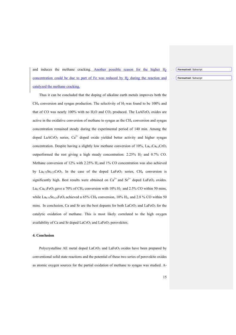
and induces the methane cracking. Another possible reason for the higher H2
concentration could be due to part of Fe was reduced by H2 during the reaction and
catalyzed the methane cracking.
Thus it can be concluded that the doping of alkaline earth metals improves both the
CH4 conversion and syngas production. The selectivity of H2 was found to be 100% and
that of CO was nearly 100% with no H2O and CO2 produced. The LaAFeO3 oxides are
active in the oxidative conversion of methane to syngas as the CH4 conversion and syngas
concentration remained steady during the experimental period of 140 min. Among the
doped LaACrO3 series, Ca2+ doped oxide yielded better activity and higher syngas
concentration. Despite having a slightly low methane conversion of 10%, La0.7Ca0.3CrO3
outperformed the rest giving a high steady concentration: 2.25% H2 and 0.7% CO.
Methane conversion of 12% with 2.25% H2 and 1% CO concentration was also achieved
by La0.75Sr0.25CrO3. In the case of the doped LaFeO3 series, CH4 conversion is
significantly high. Best results were obtained on Ca2+ and Sr2+ doped LaFeO3 oxides.
La0.7Ca0.3FeO3 gave a 70% of CH4 conversion with 10% H2 and 2.5% CO within 50 mins,
while La0.75Sr0.25FeO3 achieved a 65% CH4 conversion, 10% H2, and 2.8 % CO within 50
mins. In conclusion, Ca and Sr are the best dopants for both LaCrO3 and LaFeO3 for the
catalytic oxidation of methane. This is most likely correlated to the high oxygen
availability of Ca and Sr doped LaCrO3 and LaFeO3 perovskites.
4. Conclusion
Polycrystalline AE metal doped LaCrO3 and LaFeO3 oxides have been prepared by
conventional solid state reactions and the potential of these two series of perovskite oxides
as atomic oxygen sources for the partial oxidation of methane to syngas was studied. A-
Formatted: Subscript
Formatted: Subscript

16
site doping with AE metals generally increases the mobility of lattice oxygen ions and
thus decreases the temperatures for the hydrogen and CO production, as compared with
the undoped LaCrO3 and LaFeO3 oxides. The minor structural change during the partial
oxidation of methane in the case of LaCrO3 can be regenerated by oxidation in O2/Ar at
950 oC, while LaFeO3 showed negligible structural changes during the catalytic oxidation
reaction of methane. The results indicate stable activities of the perovskites during the
repeated reaction cycles of generation-regeneration. LaAFeO3 series yield better
performance than the LaACrO3 series. The best results were obtained on (La0.75Sr0.25)FeO3
with 65% of CH4 conversion, 10 % H2 and 2.8% CO production at 850 oC with 100% H2
selectivity. The high activity of (La0.75Sr0.25)FeO3 is most likely due to the highly mobile
lattice oxide ions, indicated by the low reducing temperature (~400 oC) in H2 and a high
mole ratio of 1.37 (H2 consumed per catalyst used). (La0.75Sr0.25)FeO3 shows a promising
potential as atomic oxygen source for syngas production via the reaction of methane for
portable fuel cells applications.
Acknowledgments
The work was carried out in the frame of Joint Project between Institute Chemical
Engineering Science (A*STAR) and Nanyang Technological University Singapore
(NTU), with funding from Economic and development board, Singapore (EDB) and
partially supported by Australia Research Council (LP110200281), Australia.
References:
1. Barreto L, Makihira A, Riahi K. The hydrogen economy in the 21st century: a sustainable development scenario. Int J Hydrog Energy 2003; 28:267-84.
2. Agnolucci P. Hydrogen infrastructure for the transport sector. Int J Hydrog Energy 2007; 32:3526-44.

17
3. Izquierdo U, Barrio VL, Cambra JF, Requies J, Guemez MB, Arias PL, Kolb G, Zapf R, Gutierrez AM, Arraibi JR. Hydrogen production from methane and natural gas steam reforming in conventional and microreactor reaction systems. Int J Hydrog Energy 2012; 37:7026-33.
4. Liu HM, He DH. Recent Progress on Ni-Based Catalysts in Partial Oxidation of Methane to Syngas. Catal Surv Asia 2012; 16:53-61.
5. Zhang L, He HQ, Kwek WR, Ma J, Tang EH, Jiang SP. Fabrication and Characterization of Anode-Supported Tubular Solid-Oxide Fuel Cells by Slip Casting and Dip Coating Techniques. J Am Ceram Soc 2009; 92:302-10.
6. Colpan CO, Dincer I, Hamdullahpur F. Thermodynamic modeling of direct internal reforming solid oxide fuel cells operating with syngas. Int J Hydrog Energy 2007; 32:787-95.
74. Soria MA, Mateos-Pedrero C, Guerrero-Ruiz A, Rodriguez-Ramos I. Thermodynamic and experimental study of combined dry and steam reforming of methane on Ru/ZrO2-La2O3 catalyst at low temperature. Int J Hydrog Energy 2011; 36:15212-20.
85. Fan MS, Abdullah AZ, Bhatia S. Catalytic Technology for Carbon Dioxide Reforming of Methane to Synthesis Gas. Chemcatchem 2009; 1:192-208.
6. Liu HM, He DH. Recent Progress on Ni-Based Catalysts in Partial Oxidation of Methane to Syngas. Catal Surv Asia 2012; 16:53-61.
7. Zhang L, He HQ, Kwek WR, Ma J, Tang EH, Jiang SP. Fabrication and Characterization of Anode-Supported Tubular Solid-Oxide Fuel Cells by Slip Casting and Dip Coating Techniques. J Am Ceram Soc 2009; 92:302-10.
8. Colpan CO, Dincer I, Hamdullahpur F. Thermodynamic modeling of direct internal reforming solid oxide fuel cells operating with syngas. Int J Hydrog Energy 2007; 32:787-95.
9. Freni S, Calogero G, Cavallaro S. Hydrogen production from methane through catalytic
partial oxidation reactions. J Power Sources 2000; 87:28-38. 10. Chroneos A, Vovk RV, Goulatis IL, Goulatis LI. Oxygen transport in perovskite and
related oxides: A brief review. J Alloy Compd 2010; 494:190-5. 11. Shao ZP, Yang WS, Cong Y, Dong H, Tong JH, Xiong GX. Investigation of the permeation
behavior and stability of a Ba0.5Sr0.5Co0.8Fe0.2O3-delta oxygen membrane. J Membr Sci 2000; 172:177-88.
12. Saracco G, Specchia V. Catalytic Inorganic-Membrane Reactors - Present Experience and Future Opportunities. Catal Rev-Sci Eng 1994; 36:305-84.
13. Cook RL, Macduff RC, Sammells AF. Perovskite Solid Electrolytes for Intermediate Temperature Solid Oxide Fuel-Cells. J Electrochem Soc 1990; 137:3309-10.
14. Dailly J, Fourcade S, Largeteau A, Mauvy F, Grenier JC, Marrony M. Perovskite and A(2)MO(4)-type oxides as new cathode materials for protonic solid oxide fuel cells. Electrochim Acta 2010; 55:5847-53.
15. Ding HP, Xue XJ. Novel layered perovskite GdBaCoFeO5+delta as a potential cathode for proton-conducting solid oxide fuel cells. Int J Hydrog Energy 2010; 35:4311-5.
16. Jiang SP. Development of lanthanum strontium manganite perovskite cathode materials of solid oxide fuel cells: a review. J Mater Sci 2008; 43:6799-833.
17. Alcock CB, Doshi RC, Shen Y. Perovskite Electrodes for Sensors. Solid State Ionics 1992; 51:281-9.
18. Blasin-Aube V, Belkouch J, Monceaux L. General study of catalytic oxidation of various VOCs over La0.8Sr0.2MnO3+x perovskite catalyst - influence of mixture. Appl Catal B-Environ 2003; 43:175-86.
19. Chen HQ, Yu H, Peng F, Yang GX, Wang HJ, Yang J, Tang Y. Autothermal reforming of ethanol for hydrogen production over perovskite LaNiO3. Chem Eng J 2010; 160:333-9.

18
20. Pena MA, Fierro JLG. Chemical structures and performance of perovskite oxides. Chem Rev 2001; 101:1981-2017.
21. Sutthiumporn K, Maneerung T, Kathiraser Y, Kawi S. CO2 dry-reforming of methane over La0.8Sr0.2Ni0.8M0.2O3 perovskite (M = Bi, Co, Cr, Cu, Fe): Roles of lattice oxygen on C-H activation and carbon suppression. Int J Hydrog Energy 2012; 37:11195-207.
22. Goldwasser MR, Rivas ME, Lugo ML, Pietri E, Perez-Zurita J, Cubeiro ML, Griboval-Constant A, Leclercq G. Combined methane reforming in presence of CO2 and O-2 over LaFe1-xCOxO3 mixed-oxide perovskites as catalysts precursors. Catal Today 2005; 107-08:106-13.
23. Provendier H, Petit C, Estournes C, Libs S, Kiennemann A. Stabilisation of active nickel catalysts in partial oxidation of methane to synthesis gas by iron addition. Appl Catal A-Gen 1999; 180:163-73.
24. Slagtern A, Olsbye U. PARTIAL OXIDATION OF METHANE TO SYNTHESIS GAS-USING LA-M-O CATALYSTS. Appl Catal A-Gen 1994; 110:99-108.
25. Toniolo FS, Magalhaes R, Perez CAC, Schmal M. Structural investigation of LaCoO3 and LaCoCuO3 perovskite-type oxides and the effect of Cu on coke deposition in the partial oxidation of methane. Appl Catal B-Environ 2012; 117:156-66.
26. Goldwasser MR, Rivas ME, Pietri E, Perez-Zurita MJ, Cubeiro ML, Gingembre L, Leclercq L, Leclercq G. Perovskites as catalysts precursors: CO2 reforming of CH4 on Ln(1-x)Ca(x)Ru(0.8)Ni(0.2)O(3) (Ln = La, Sm, Nd). Appl Catal A-Gen 2003; 255:45-57.
27. Kim J, Kim T, Yoo JW, Lee KB, Hong SI. Carbon dioxide reforming of methane to synthesis gas over LaNi1-xCrxO3 perovskite catalysts. Korean J Chem Eng 2012; 29:1329-35.
28. Moradi GR, Khosravian F, Rahmanzadeh M. Effect of Partial Substitution of Ni by Cu in LaNiO3 Perovskite Catalyst for Dry Methane Reforming. Chin J Catal 2012; 33:797-801.
29. Watanabe R, Sekine Y, Kojima J, Matsukata M, Kikuchi E. Dehydrogenation of ethylbenzene over highly active and stable perovskite oxide catalyst - Effect of lattice oxygen on/in perovskite oxide and role of A/B site in perovskite oxide. Appl Catal A-Gen 2011; 398:66-72.
30. Sadykov VA, Sazonova NN, Bobin AS, Muzykantov VS, Gubanova EL, Alikina GM, Lukashevich AI, Rogov VA, Ermakova EN, Sadovskaya EM, Mezentseva NV, Zevak EG, Veniaminov SA, Muhler M, Mirodatos C, Schuurman Y, van Veen AC. Partial oxidation of methane on Pt-supported lanthanide doped ceria-zirconia oxides: Effect of the surface/lattice oxygen mobility on catalytic performance. Catal Today 2011; 169:125-37.
31. Li KZ, Wang H, Wei YG, Yan DX. Syngas production from methane and air via a redox process using Ce-Fe mixed oxides as oxygen carriers. Appl Catal B-Environ 2010; 97:361-72.
32. Salazar-Villalpando MD, Berry DA, Cugini A. Role of lattice oxygen in the partial oxidation of methane over Rh/zirconia-doped ceria. Isotopic studies. Int J Hydrog Energy 2010; 35:1998-2003.
33. Shen Y, Liu MN, He TM, Jiang SP. A potential interconnect material for solid oxide fuel cells: Nd0.75Ca0.25Cr0.98O3-delta. J Power Sources 2010; 195:977-83.
34. Boroomand F, Wessel E, Bausinger H, Hilpert K. Correlation between defect chemistry and expansion during reduction of doped LaCrO3 interconnects for SOFCs. Solid State Ionics 2000; 129:251-8.
35. Fergus JW. Lanthanum chromite-based materials for solid oxide fuel cell interconnects. Solid State Ionics 2004; 171:1-15.
36. Simner SP, Anderson MD, Stevenson JW. La(Sr)FeO3 SOFC cathodes with marginal copper doping. J Am Ceram Soc 2004; 87:1471-6.
37. Simner SP, Shelton JP, Anderson MD, Stevenson JW. Interaction between La(Sr)FeO3 SOFC cathode and YSZ electrolyte. Solid State Ionics 2003; 161:11-8.
38. Minh NQ. Ceramic Fuel-Cells. J Am Ceram Soc 1993; 76:563-88.

19
39. Tu HY, Takeda Y, Imanishi N, Yamamoto O. Ln(0.4)Sr(0.6)Co(0.8)Fe(0.2)O(3-delta) (Ln = La, Pr, Nd, Sm, Gd) for the electrode in solid oxide fuel cells. Solid State Ionics 1999; 117:277-81.
40. Ong KP, Wu P, Liu L, Jiang SP. Optimization of electrical conductivity of LaCrO3 through doping: A combined study of molecular modeling and experiment. Appl Phys Lett 2007; 90.
41. Sfeir J, Buffat PA, Mockli P, Xanthopoulos N, Vasquez R, Mathieu HJ, Van herle J, Thampi KR. Lanthanum chromite based catalysts for oxidation of methane directly on SOFC anodes. J Catal 2001; 202:229-44.
42. Sfeir J. LaCrO3-based anodes: stability considerations. J Power Sources 2003; 118:276-85.

20
Figure captions:
1. Syngas production and regeneration steps over ABO3 perovskite oxides.
2. Schematic diagram of the experimental set-up.
3. XRD patterns of (a) as-prepared LaCrO3, LaCrO3 after generation in 5%CH4/Ar at
900ºC, and LaCrO3 after regeneration in 5%O2/Ar at 950ºC; and (b) as-prepared
LaFeO3, LaFeO3 after generation in 5%CH4/Ar at 950ºC, and LaFeO3 after
regeneration in 5%O2/Ar at 950ºC.
4. XRD patterns of the as-prepared (a) doped LaCrO3 oxides and (b) doped LaFeO3
oxide series.
5. TPR profiles of (a) doped LaCrO3 and (b) doped LaFeO3 oxides, showing the
intensity, temperature and time on stream at which H2 is consumed from the reaction
between H2 and perovskite oxides. The flow rate was 50 mLml/min of 5%H2/Ar,
and the weight of each sample is 50 mg. The temperature was raised at a rate of
10 °C/min from room temperature to 900 ºC.
6. MS profiles of oxidation of methane (5%CH4/Ar) over (a) doped LaCrO3 and (b)
doped LaFeO3 oxides, showing the intensity and temperature at which H2 is
produced and detected by mass spectrometer. The flow rate was 100 ml/min of
5%CH4/Ar, and the weight of each sample is 100 mg. The temperature was raised at
a rate of 10 °C/min from room temperature to 950 ºC.
7. Plots of catalytic activity of partial oxidation of methane of 5%CH4, measured at
850C, GHSV of 750 h-1 over doped LaCrO3 and LaFeO3 oxides respectively: (a, b)
CH4 conversion, (c, d) H2 concentration, and (e, f) CO concentration.
8. Plots of molar ratio of H2/CO produced over (a) doped LaCrO3 and (b) doped
LaFeO3 oxides. The data were taken from Fig.7c-f.

21
Table 1. BET surface areas of as-prepared (La1-xAx)MO3 perovskites-type oxides. Surface area (m2/g) Surface area (m2/g) LaCrO3 2.39 LaFeO3 2.99 (La0.7Ba0.3)CrO3 2.57 (La0.7Ba0.3)FeO3 3.72 (La0.7Ca0.3)CrO3 3.21 (La0.7Ca0.3)FeO3 4.76 (La0.7Mg0.3)CrO3 2.76 (La0.7Mg0.3)FeO3 5.02 (La0.75Sr0.25)CrO3 2.78 (La0.75Sr0.25)FeO3 4.97 Table 2. Number of mole of H2 being consumed per mole of perovskite oxides used, tabulated from the TPR results for the (La1-xAx)MO3 perovskites-type oxides. Moles of H2 Consumed
per one mole of Catalyst LaCrO3 0.08 (La0.7Ba0.3)CrO3 0.27 (La0.7Ca0.3)CrO3 0.60 (La0.7Mg0.3)CrO3 0.20 (La0.75Sr0.25)CrO3 0.38 LaFeO3 0.12 (La0.7Ba0.3)FeO3 1.03 (La0.7Ca0.3)FeO3 1.11 (La0.7Mg0.3)FeO3 1.26 (La0.75Sr0.25)FeO3 2.65

22
Figure 1.

23
Figure 2.
Gas Inlet
Furnace
Quartz tube with sample
Gas Outlet
GC
MS
Vent
Vent
Vent
Valve
O2/He
Ar
CH4
Process Gas
Regeneration Gas

24
20 30 40 50 60 70 80 90
LaCrO3
La (CrO4)
La (CrO3)
after regeneration in O2
after generation in CH4
Co
un
ts (
a.u
.)
2 degree)
raw
La2O
3
20 30 40 50 60 70 80 90
LaFeO3
Co
un
ts (
a.u
.)
2 deg)
after regeneration in O2
after generation in CH4
raw
Figure 3.
(a)
(b)
25
20 30 40 50 60 70 80
(b)
LaCrO3
La0.75
Sr0.25
CrO3
La0.7
Mg0.3
CrO3
La0.7
Ca0.3
CrO3C
ou
nts
(a
.u.)
2 deg)
La0.7
Ba0.3
CrO3
20 30 40 50 60 70 80
LaFeO3
La0.75
Sr0.25
FeO3
La0.7
Mg0.3
FeO3
La0.7
Ca0.3
FeO3C
ou
nts
(a
.u.)
2 deg)
La0.7
Ba0.3
FeO3
(b) iron oxides
Figure 4.
(a)

26
20 30 40 50 60 70 80 90
0
100
200
300
400
500
600
700
800
900
LaCrO3
La0.7
Mg0.3
CrO3
La0.7
Ba0.3
CrO3
La0.7
Ca.3CrO
3
La0.75
Sr0.25
CrO3
Inte
ns
ity
(a
.u.)
Time (min)
TPR results of AE doped LaCrO3 series
Te
mp
oC
(a)
20 40 60 80 100
0
100
200
300
400
500
600
700
800
900
Inte
ns
ity
(a.
u.)
Time (min)
LaFeO3
La0.7
Mg0.3
FeO3
La0.7
Ba0.3
FeO3
La0.7
Ca.3FeO
3
La0.75
Sr0.25
FeO3
TPR results of AE doped LaFeO3 series(b)
Tem
p o
C
Figure 5.

27
700 750 800 850 900 950
(L a0 .7 5
S r0 .2 5
)C rO3
(L a0 .7
M g0 .3
)C rO3
(L a0 .7
C a0 .3
)C rO3
(L a0 .7
B a0 .3
)C rO3
Inte
ns
ity
(a.u
.)
T e m p ( oC )
L a C rO3
(a )
700 750 800 850 900 950
Inte
nsi
ty (
a.u
)
Temp (oC )
(La0.75
Sr0.25
)FeO3
(La0.7
Mg0.3
)FeO3
(La0.7
Ca0.3
)FeO3
(La0.7
Ba0.3
)FeO3
LaFeO3
(b)
Figure 6.

28
0 20 40 60 80 100 120 1400
2
4
6
8
10
12
14 LaCrO3
La0.7
Ba0.3
CrO3
La0.7
Ca0.3
CrO3
La0.7
Mg0.3
CrO3
La0.75
Sr0.25
CrO3
CH
4 C
on
vers
ion
(%
)
Time on Stream (min)
(a) LaACrO3 oxides
0 20 40 60 80 100 120 140
0
10
20
30
40
50
60
70
80
CH
4 C
on
vers
ion
(%
)
Time on Stream (min)
LaFeO3
La0.7
Ba0.3
FeO3
La0.7
Ca0.3
FeO3
La0.7
Mg0.3
FeO3
La0.75
Sr0.25
FeO3
(b) LaAFeO3 oxides

29
0 20 40 60 80 100 120 1400.0
0.5
1.0
1.5
2.0
2.5
3.0
LaCrO3
La0.7
Mg0.3
CrO3
La0.7
Ca0.3
CrO
La0.7
Ba0.3
CrO
La0.75
Sr0.25
CrO
(c) LaACrO3 oxides
Con
cen
tra
tion
of H
2 (%
)
Time on Stream (min)
0 20 40 60 80 100 120 140
0
2
4
6
8
10
12
14
16
18 (d) LaAFeO3 oxides
Co
nc
en
tra
tio
n o
f H
2 (%
)
Time on Stream (min)
LaFeO3
La0.7
Ba0.3
FeO3
La0.7
Ca0.3
FeO3
La0.7
Mg0.3
FeO3
La0.75
Sr0.25
O3
30
0 20 40 60 80 100 120 140 160
0.0
0.2
0.4
0.6
0.8
1.0 LaCrO3
La0.7
Mg0.3
CrO3
La0.7
Ca0.3
CrO
La0.7
Ba0.3
CrO
La0.75
Sr0.25
CrO
Co
nc
entr
ati
on
of
CO
(%
)
Time on Stream (min)
LaACrO3 oxides (e)
0 20 40 60 80 100 120 140
0
1
2
3
4
5 LaFeO3
La0.7
Ba0.3
FeO3
La0.7
Ca0.3
FeO3
La0.7
Mg0.3
FeO3
La0.75
Sr0.25
O3
(f) LaAFeO3 oxides
Co
nc
entr
ati
on
of
CO
(%
)
Time on Stream (min)
Figure 7.
31
0 10 20 30 40 50 60 70 80
0
2
4
6
8
10
Mo
lar
Rat
io o
f H
2/CO
Time on Stream (min)
LaCrO3
La0.7
Ba0.3
CrO3
La0.7
Ca0.3
CrO3
La0.7
Mg0.3
CrO3
La0.75
Sr0.25
CrO3
(a) LaACrO3 oxides
0 10 20 30 40 50 60 70 80
0
2
4
6
8
10
12
14
16 LaFeO
3
La0.7
Ba0.3
FeO3
La0.7
Ca0.3
FeO3
La0.7
Mg0.3
FeO3
La0.75
Sr0.25
FeO3
Mo
lar
Ra
tio
of
H2/C
O
Time on Stream (min)
LaAFeO3 oxides (b)
Figure 8.