Embed Size (px)
Citation preview

Abstract— Gasification of biomass and coal is an attractive
technology for combined heat and power production, as well as for synthesis processes such as the production of liquid and gaseous biofuels. The allothermal steam blown gasification process yields a high calorific product gas, practically free of nitrogen. Originally, the system was designed for biogeneous fuels and residues but it can also handle a large number of other fuels such as several types of coal. To demonstrate the influence on the system performance of hard coal as an example of a solid fossil fuel a fuel blend of wood pellets and hard coal was fed into the DFB gasifier. The fuel blend ratio was 20 % coal in terms of energy. The DFB pilot plant was operated at a fuel power of 78 kW and a steam to fuel ratio of 1.0 kg/kgdb during the investigations. The system was operated at gasification temperatures between 830 and 870 °C. This paper points out the influence of the temperature on the system in terms of product performance, syngas quality as well as process efficiency.
Index Terms—Coal, co-gasification, wood, biomass.
I. INTRODUCTION Gasification of biomass is, especially since the last decades,
a major topic in the area of the energetic utilization of biomass. One big issue in the gasification of biomass is that the feedstock is often only available locally at a certain period of the year in large amounts. Co-gasification of biomass, as the designated feedstock, with a cheap fossil fuel could help to overcome this problem as fuel flexibility is the key feature for an economic breakthrough. It also offers the opportunity to build larger plants with higher feedstock flexibility as the combination with coal overcomes the drawback of the relatively low specific energy content of biomass-derived fuels. Conventionally, autothermal gasification processes always require an oxidizing gasification agent, like air. This results in the drawback of a syngas with a low heating value as it is diluted with nitrogen. Especially for further synthesis processes [1] (e.g. Fischer-Tropsch synthesis, synthetic natural gas production, methanol synthesis) this dilution is a big drawback. Dual fluidized bed gasification solves this problem as the combustion zone, which provides the energy for gasification, is separated from the gasification zone and pure steam is used as a gasification agent. This gasification
Manuscript received February 9, 2012; revised March 10, 2012. This
work was carried out under the EU Project Flexgas (CONTRACT N° RFCR-CT-2007-00005) and under the EU Project Fecundus (CONTRACT N° RFCR-CT-2010-00009).
S. Kern, C. Pfeifer and H. Hofbauer are with the Institute of Chemical Engineering at Vienna University of Technology, Getreidemarkt 9/166, 1060 Vienna, Austria (e-mail: [email protected]).
technology [2] has been developed at Vienna University of Technology and is successfully demonstrated in Güssing and Oberwart, Austria, on the 8 and 10 MWth scale, respectively, since 2001 and 2008 [3, 4]. Further plants in Villach, Austria [2], Gothenburg, Sweden [2] and Senden, Germany are currently under construction and will gain a fuel power of 15 MW (Villach, Senden) and 32 MW (Gothenburg). A previous investigation about co-gasification of coal and wood in the 100 kW dual fluidized bed gasification pilot plant at VUT with coal ratios from 0 to 100 % showed that the gasification system can also be operated with coal at different ratios at pilot scale [5, 10]. The next step was the test at industrial scale. During an experimental campaign, the combined heat and power (CHP) gasification plant in Güssing was operated with coal ratios of up to 22 % in terms of energy. These tests were successful as they showed that the dual fluidized bed design could also handle coal as a fuel at commercial operation [6]. The addition of 20 % of coal (in terms of energy) can be beneficial for the process and its performance as by the lower reaction activity of the coal, the residence time of the coal/coke mixture in the system is longer and therefore accumulates to a higher level than when only using biomass as a fuel. This reduces for example pressure and producer gas fluctuations in the gasifier and effects changes in the product gas composition. Abu El-Rub et al. [7] summarized that char has also a quite important potential to act as a catalyst for tar reduction in the gasification process. The main gasification reactions are shown in Table I.
TABLE I: EQUILIBRIUM REACTIONS OF THE MAIN GAS COMPONENTS [8, 9] Name of reaction Chemical equation ΔH [kJ/mol] Equ.
Water-gas shift CO + H2O ↔ CO2 + H2 −40,9 [1]
Methane reforming CO + 3 H2 ↔ CH4 + H2O -225 [2]
Water-gas (i) C + H2O ↔ CO + H2 118,5 [3]
Water-gas (ii) C + 2 H2O ↔ CO2 + 2 H2 103 [4]
Boudouard C + CO2 ↔ 2 CO 159,9 [5]
Methanation C + 2 H2 ↔ CH4 -87,5 [6]
Oxidation (i) C + O2 ↔ CO2 -393,5 [7]
Oxidation (ii) C + 0.5 O2 ↔ CO -123,1 [8]
These reactions are considered as equilibrium reactions with variable equilibrium depending on gas concentrations, temperature and pressure, however, in a real gasifier a complete state of equilibrium will not be reached. In the gasifier these reactions can take place at the same time and location and some reactions can be forced by operating
Synergetic Utilization of Biomass and Fossil Fuels: Influence of Temperature in Dual Fluidized Bed Steam
Co-gasification of Coal and Wood
Stefan Kern, Christoph Pfeifer, and Hermann Hofbauer
International Journal of Environmental Science and Development, Vol. 3, No. 3, June 2012
294
parameters and by the utilization of catalytic bed material. In this paper there will be a focus on the possibility of process optimization by changed gasification temperatures. A series of tests with gasification temperatures between 830 and 870 °C will be discussed with a focus on gas quality and process efficiency. The test series was accomplished with a fuel blend ratio of wood pellets with 20% of coal in terms of energy.
II. EXPERIMENTAL
A. Experimental Setup For the experiments on the pilot scale, at Vienna
Universgity of Technology, a dual fluidized bed gasification reactor is in operation. The basic principle of the dual fluidized bed gasification process is shown in Fig. 1 and a schematic drawing of the pilot rig is shown in Fig. 2. This system separates gasification and combustion as two fluidized bed reactors connected together by loop seals are used. The fuel, usually biomass, enters the gasification reactor, a bubbling bed fluidized with steam, where drying, pyrolysis and heterogeneous char gasification take place at temperatures of up to 900 °C. The remaining residual char leaves the gasification reactor at the bottom together with the bed material, which circulates between the two reactors, through the lower loop seal to the combustion reactor. This reactor is implemented as a fast fluidized bed that is fluidized with air to maintain combustion of the residual char and additional fuel, if required. By burning char and additional fuel in the combustion reactor, the bed material is heated up, and after particle separation from the flue gas at the exit of the combustion reactor, it flows back to the gasifier via the upper loop seal. Both the lower and upper loop seals are fluidized with steam to ensure a high throughput of bed material and to avoid any leakage of gas between the reactors. In practical operations, the gasification temperature is normally controlled by the addition of fuel (e.g. recycled producer gas, sawdust, etc.) into the combustion reactor. In the case of the 100 kW pilot plant, light heating oil is used as an additional fuel as it is easy to handle for processes on pilot scale. The pressure in both gasification and combustion reactors is close to atmospheric conditions. The main basic geometry data of the dual fluidized bed reactor system is summarized in Table II.
Fig. 1. Principles behind the dual fluidized bed gasification system
Fig. 2. Schematic drawing of the pilot gasifier
TABLE II: BASIC GEOMETRY DATA OF THE DUAL FLUIDIZED BED SYSTEM
Unit Gasification reactor Combustion Reactor
Geometry Conical bottom section
with square-shaped upper freeboard section
Cylindrical
Reactor inner diameter [mm] 304 (equivalent
cylindrical diameter) 98
Reactor free height [m] 2.35 3.9
The process yields two separate gas streams at high
temperatures: a high quality producer gas and a conventional flue gas. The producer gas for biomass gasification is generally characterized by a relatively low content of condensable higher hydrocarbons (2-10 g/Nm³ of so called tars, heavier than toluene), low N2 (< 1 vol%db), and a high H2 content of 35-40 vol%db. A more detailed description of the dual fluidized bed gasifier used at VUT can be found in [2, 5].
B. Analytics The permanent gases in the syngas, CH4, H2, CO, CO2, and
O2, were measured online by a Rosemount NGA2000 and N2, C2H4, C2H6, and C3H8 by an online gas chromatograph. Tar, NH3 and H2S were sampled isokinetically using absorption bottles with toluene, diluted sulfuric acid or aqueous potassium hydroxide solution. In the flue gas of the combustion reactor (riser) CO2, CO and O2 were detected online again by a Rosemount NGA2000. Details of the measurement methods can be found in [10].
C. Balance of the pilot plant The complexity of the gasification processes is high and
International Journal of Environmental Science and Development, Vol. 3, No. 3, June 2012
295

requires thermodynamic calculations. That is why the calculation of mass and energy balances has to be done using computer-aided methods. For this purpose, the balance tool IPSEpro was used. IPSEpro is a stationary, equation-oriented flow sheet simulation tool that has been developed for power systems [11]. It has been used at the Institute of Chemical Engineering for biomass-based energy systems for many years and therefore the models of the process are constantly being improved and advanced. Detailed information on IPSEpro, its mode of operation and its utilization for biomass-based energy systems is summarized by Pröll et al. [12].
III. RESULTS AND DISCUSSION For this test campaign, a fuel power (wood pellets and coal)
of about 78 kW was chosen. A fuel blend ratio of 20% coal in terms of energy has been chosen based on previous test campaigns [Ref. Diss Isa]. The fluidizing conditions were kept constant for all three tests, so there was always the same amount of steam and air for fluidization present. Wood pellets produced according to the Austrian standard ÖNORM M 7135 are usually used as a standard fuel to represent wood in the gasifier. For the processing of biomass in a power plant, wood chips are mostly the designated fuel, but for the pilot plant, the pieces have to be smaller, and the quality of the fuel has to be held constant for the entire test campaign. Therefore, instead of wood chips, wood pellets are normally used for the tests. Furthermore, it was found during previous tests that wood pellets behave similar to wood chips in the dual fluidized bed gasifier [2]. The coal used in these tests was Polish hard coal. Polish coal was chosen as it is widely used in Austria for coal-fired power plants. The proximate and ultimate analyses of these two fuels are listed in Table III.
TABLE III: PROXIMATE AND ULTIMATE ANALYSIS OF THE FUELS Polish hard coal wood pellets
dry basis as used dry basis as used
water content
[wt. %]
- 9.86 - 6.11 ash content 7.41 6.68 0.29 0.27 C 76.49 68.95 50.23 47.16 H 3.87 3.49 6.04 5.67 N 1.34 1.21 0.05 0.05 O 10.29 9.26 43.38 40.73 S Cl
0.455 0.15
0.410 0.14
0.005 0.003
0.005 0.003
volatile matter [wt. %] 34.66 31.24 86.45 81.17 fixed carbon [wt.%] 65.34 58.90 13.55 12.72 LHV [MJ/kg] 29.15 26.03 18.75 17.46
The bed material used in the reactor was calcined olivine.
It was chosen as it shows a catalytic activity for tar reduction and is perceived as a natural catalyst [13, 14]. For each test in the pilot plant a new batch of olivine with an initial mass of 100 kg was used. Three tests at gasification temperatures of 830 °C, 860 °C and 870 °C were carried out. The key data of the accomplished test runs are summarized in Table IV. Fig. 3 shows the main syngas components and Fig. 4 displays the higher hydrocarbons as well as the lower heating value. Hydrogen increased from 42.5 to 45.7 vol.%db and carbon
monoxide increased from 24.8 to 26.3 vol.%db in the syngas, whereas carbon dioxide and methane decreased as an effect of higher gasification temperatures. Also, the higher hydrocarbons ethylene (C2H4) and ethane (C2H6) decreased, though the most rigorous decrease was ascribed to ethylene. Only propane (C3H8) did not show any significant change and remains approximately constant.
TABLE IV: KEY DATA OF THE GASIFICATION TESTS
gasification temperature [°C] 830 ± 2 860 ± 2 870 ± 2
mean combustion temperature [°C] 889 939 932
fuel size coal [mm] 6 ± 2
fuel size wood pellets (diameter x length) [mmxmm] Ø 6 x 30 (max.)
fluidization mass flow gasifier (steam) [kg/h] 8.4 ± 0.2
fluidization flow combustor (primary air) [Nm³/h] 4.6 ± 0.0
fluidization flow combustor (secondary air)
[Nm³/h] 50.0 ± 0.2
fuel mass flow (coal + wood)
[kg/h] 15.4 ± 0.2
steam/fuel ratio ϕsf [kg/kgdb] 1.0
Fig. 3. Main syngas components vs. gasification temperature
Fig. 4. Higher hydrocarbons and lower heating value vs. gasification
temperature
International Journal of Environmental Science and Development, Vol. 3, No. 3, June 2012
296
The specific gas yields are given in Table V. The net effect of these changes of the syngas composition was a slight decrease of the lower heating value of the gas, as the major contribution to the LHV was provided by methane and the higher hydrocarbons and their relatively high heating value. In Table 5 there can be seen that in general a higher gasification temperature increases the overall gas yield, which results in a higher energy consumption for gasification. This fact will be strengthened later on (Fig. 9).
TABLE V: SPECIFIC GAS YIELDS
gasification temperature [°C] 830 860 870
specific H2 yield [Nm³H2/kgfuel,daf] 0.514 0.673 0.690
specific CO2 yield [Nm³CO2/kgfuel,daf] 0.240 0.274 0.269
specific CO yield [Nm³CO/kgfuel,daf] 0.300 0.376 0.397
specific CH4 yield [Nm³CH4/kgfuel,daf] 0.118 0.122 0.123
specific C2H4 yield [Nm³C2H4/kgfuel,daf] 0.027 0.021 0.021
specific C2H6 yield [Nm³C2H6/kgfuel,daf] 0.002 0.001 0.001
specific C3H8 yield [Nm³C3H8/kgfuel,daf] 0.003 0.004 0.004
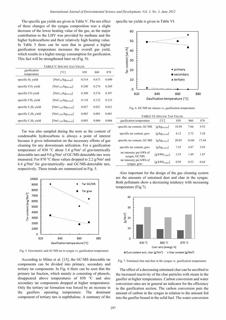
Tar was also sampled during the tests as the content of
condensable hydrocarbons is always a point of interest because it gives information on the necessary efforts of gas cleaning for any downstream utilization. For a gasification temperature of 830 °C about 3.4 g/Nm³ of gravimetrically detectable tars and 9.0 g/Nm³ of GC/MS-detectable tars were measured. For 870 °C these values dropped to 2.2 g/Nm³ and 6.4 g/Nm³ for gravimetrically- and GC/MS-detectable tars, respectively. These trends are summarized in Fig. 5.
Fig. 5. Gravimetric and GC/MS tar in syngas vs. gasification temperature
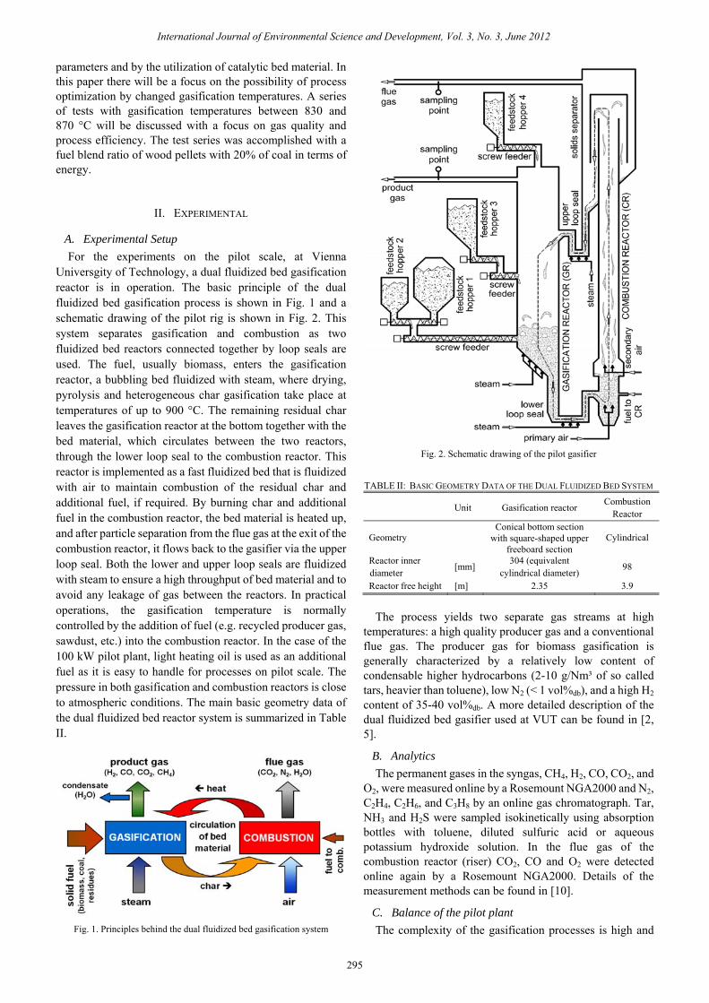
According to Milne et al. [15], the GC/MS detectable tar
components can be divided into primary, secondary and tertiary tar components. In Fig. 6 there can be seen that the primary tar fraction, which mainly is consisting of phenols, disappeared above temperatures of 850 °C and also secondary tar components dropped at higher temperatures. Only the tertiary tar formation was forced by an increase in the gasifiers operating temperature. The dominant component of tertiary tars is naphthalene. A summary of the
specific tar yields is given in Table VI.
Fig. 6. GC/MS tar classes vs. gasification temperature
TABLE VI: SPECIFIC TAR YIELDS gasification temperature [°C] 830 860 870
specific tar content, GC/MS [g/kgfuel,daf] 10.94 7.66 9.52
specific tar content, grav. [g/kgfuel,daf] 4.12 2.72 3.24
specific tar content, GC/MS [g/kgcarbon] 20.05 14.04 17.44
specific tar content, grav. [g/kgcarbon] 7.55 4.97 5.93
tar intensity per kWh of syngas, GC/MS [g/kWhsyngas] 2.53 1.49 1.87
tar intensity per kWh of syngas, grav. [g/kWhsyngas] 0.95 0.53 0.64
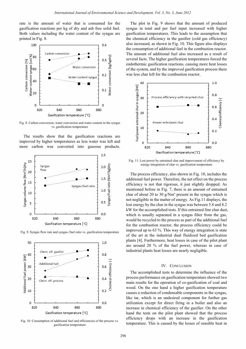
Also important for the design of the gas cleaning system
are the amounts of entrained dust and char in the syngas. Both pollutants show a decreasing tendency with increasing temperature (Fig.7).
Fig. 7. Entrained char and dust in the syngas vs. gasification temperature The effect of a decreasing entrained char can be ascribed to
the increased reactivity of the char particles with steam in the gasifier at higher temperatures. Carbon conversion and water conversion rates are in general an indicator for the efficiency in the gasification section. The carbon conversion puts the amount of carbon in the syngas in relation to the amount fed into the gasifier bound in the solid fuel. The water conversion
International Journal of Environmental Science and Development, Vol. 3, No. 3, June 2012
297
rate is the amount of water that is consumed for the gasification reactions per kg of dry and ash free solid fuel. Both values including the water content of the syngas are printed in Fig. 8.
Fig. 8. Carbon conversion, water conversion and water content in the syngas
vs. gasification temperature The results show that the gasification reactions are
improved by higher temperatures as less water was left and more carbon was converted into gaseous products.
Fig. 9. Syngas flow rate and syngas-/fuel ratio vs. gasification temperature
Fig. 10. Consumption of additional fuel and efficiencies of the process vs.
gasification temperature
The plot in Fig. 9 shows that the amount of produced syngas in total and per fuel input increased with higher gasification temperatures. This leads to the assumption that the chemical efficiency in the gasifier (cold gas efficiency) also increased, as shown in Fig. 10. This figure also displays the consumption of additional fuel in the combustion reactor. The amount of additional fuel also increased as a result of several facts. The higher gasification temperatures forced the endothermic gasification reactions, causing more heat losses of the system, and by the improved gasification process there was less char left for the combustion reactor.
Fig. 11. Lost power by entrained char and improvement of efficiency by
energy integration of char vs. gasification temperature The process efficiency, also shown in Fig. 10, includes the
additional fuel power. Therefore, the net effect on the process efficiency is not that rigorous, it just slightly dropped. As mentioned before in Fig. 7, there is an amount of entrained char of about 20 to 30 g/Nm³ present in the syngas which is not negligible in the matter of energy. As Fig.11 displays, the lost energy by the char in the syngas was between 5.8 and 8.2 kW for the accomplished tests. If this entrained fine char dust, which is usually separated in a syngas filter from the gas, would be recycled to the process as part of the additional fuel for the combustion reactor, the process efficiency could be improved up to 63 %. This way of energy integration is state of the art at the industrial dual fluidized bed gasification plants [4]. Furthermore, heat losses in case of the pilot plant are around 20 % of the fuel power, whereas in case of industrial plants heat losses are nearly negligible.
IV. CONCLUSION The accomplished tests to determine the influence of the
process performance on gasification temperature showed two main results for the operation of co-gasification of coal and wood. On the one hand a higher gasification temperature causes a reduction of condensable components in the syngas, like tar, which is an undesired component for further gas utilization except for direct firing in a boiler and also an increase in chemical efficiency of the gasifier. On the other hand the tests on the pilot plant showed that the process efficiency drops with an increase in the gasification temperature. This is caused by the losses of sensible heat in
International Journal of Environmental Science and Development, Vol. 3, No. 3, June 2012
298
flue gas and syngas, but the major heat losses are in case of the pilot plant the heat losses caused by radiation and convection directly of the plant. The heat loss of the pilot plant is usually around 20 % at a gasification temperature of 850 °C, whereas for large scale industrial plants heat losses are negligible.
Summarizing, the dual fluidized bed gasification process is a reliable technology for thermo-chemical conversion of carbonaceous feedstock to a high quality product gas. Process parameters have to be chosen depending on the utilization route as well as on the fuel characteristics. Generally, increased operation temperature improves the gas quality but reduces the overall process efficiency.
ACKNOWLEDGMENT The authors wish to acknowledge the financial support of
the European Commission since this work was carried out under the EU Project Flexgas (CONTRACT N° RFCR-CT-2007-00005) and under the EU Project Fecundus (CONTRACT N° RFCR-CT-2010-00009). Moreover, the authors would like to express their thanks to the team members of the “Testing Laboratory for Combustion Systems” at the Vienna University of Technology for the measurements as well as their support in analytical concerns.
REFERENCES [1] A. Demirbas, “Progress and recent trends in biofuels”, Progress in
Energy and Combustion Science, 33, pp. 1-18, 2007. [2] C. Pfeifer, S. Koppatz, H. Hofbauer, “Steam gasification of various
feedstocks at a dual fluidised bed gasifier: Impacts of operation conditions and bed materials”, Biomass Conversion and Biorefinery, 1, pp. 39–53, 2011.
[3] H. Hofbauer, R. Rauch, K. Bosch, R. Koch, C. Aichernig, “Biomass CHP plant Güssing - A success story”, In Bridgewater A.V. (ed.), CPL Press 2003, Liberty House, New Greenham Park, Newsbury, Berks RG19 3UP, UK , ISBN: 1872691773, 527 - 536.
[4] F. Kirnbauer, J. Kotik, H. Hofbauer, “Investigations on inorganic matter in DFB biomass steam-gasification plants in Güssing/Austria and Oberwart/Austria” in proc. 19th European Biomass Conference, 6-10 June, Berlin 2011, Germany.
[5] I. Aigner., "Co-gasification of coal and wood with steam in a dual fluidized bed gasifier", Ph.D. dissertation, Dept. Chem. Eng., Vienna University of Technology, Vienna, Austria, 2010.
[6] C. Pfeifer, I. Aigner, H. Hofbauer, “Co-gasification of biomass and coal in an 8MW dual fluidized bed steam gasifier”. In Pugsley, T. et al. (Eds.), in proc. of the 10th International Conference on Circulating Fluidized Bed Technology (CFB10), May 1-5, 2011, Sunriver, Oregon, USA.
[7] Z. Abu El-Rub, E. A. Bramer, G. Brem, “Review of Catalysts for Tar Elimination in Biomass Gasification”, Ind. Eng. Chem. Res, 43, pp. 6911-6919, 2004.
[8] P. A. Simell, J. O. Hepola, A. O. I. Krause, “Effects of gasification gas components on tar and ammonia decomposition over hot gas cleanup catalysts”, Fuel, 76(12), pp. 1117–1127, 1997.
[9] M. Kaltschmitt, H. Hartmann, H. Hofbauer, Energie aus Biomasse, Berlin, Heidelberg: Springer, 2009.
[10] S. Kern, C. Pfeifer, H. Hofbauer, “Dual fluidized bed steam gasification of solid feedstock: matching syngas requirements with fuel mixtures” in: Luckos, T. and P. den Hoed (Eds.), Proc. Industrial Fluidization South Africa (IFSA 2011), November 16-17, 2011, Johannesburg, South Africa: pp. 67-78, ISBN 978-1-920410-25-4.
[11] E. Perz, “A computer method for thermal power cycle calculation”, Journal of Engineering for Gas Turbines and Power, 113(2), pp. 184–189, 1991.
[12] T. Pröll, H. Hofbauer, "Development and Application of a Simulation Tool for Biomass Gasification Based Processes", International Journal of Chemical Reactor Engineering, vol. 6, 89, 1991.
[13] L. Devi, M. Craje, P. Thüne, K. J. Ptasinski, F. J. J. G. Janssen, “Olivine as tar removal catalyst for biomass gasifiers: catalyst characterization”, Appl Catal A, 294(1), pp. 68–79, 2005.
[14] R. Rauch, C. Pfeifer, K. Bosch, H. Hofbauer, D. Świerczyński, C. Courson, A. Kiennemann, “Comparison of different Olivines for Biomass Steam Gasification”, in proc. of the Conference for Science in Thermal and Chemical Biomass Conversion, Victoria, Canada, 30. Aug.–3. Sep, 2004, vol. 1, pp.799-809.
[15] T. A. Milne, N. Abatzoglou, R. J. Evans, “Biomass Gasifier ‘Tars’: Their Nature, Formation, and Conversion”, National Renewable Energy Lab, Golden, CO, USA, 1998.
Stefan Kern, born 1985 in Eisenstadt, Austria started his technical education in 2000 with a secondary college for engineering with a focus on automation and mechatronics which he finished in 2005. After his study of chemical process engineering at Vienna University of Technology with a focus on plant and process technology and energy technology, he graduated in 2010. The master thesis dealt with rotary kiln pyrolysis of agricultural
residues in a 3 MW pilot plant. In 2010 he worked in Indonesia as a process engineer and returned in the same year back to Vienna University of Technology to join the research group Gasification and Gas Cleaning at the Institute of Chemical Engineering as a junior researcher. The current focus is set on the research on dual fluidized bed gasification technology with a focus on co-gasification of fossil fuels with wood or residues.
Christoph Pfeifer, received a Dipl.-Ing. in Chemical Engineering and a Dr.techn. in Mechanical Engineering at the Vienna University of Technology both with works on catalytic tar removal for the dual fluidised bed gasification process. He leads the working group Gasification and Gas Cleaning since 2010. He is involved in the development of an innovative new concept for dual fluidized bed gasification process, cold flow modeling of fluidised
bed systems as well as steam reforming of tars from gasification processes.
Hermann Hofbauer received a Dipl.Ing. in Mechanical Engineering and Dr. techn. in Chemical Engineering at the Vienna University of Technology. He was appointed as full Professor for Chemical Engineering at the Vienna University of Technology in 1997. He is Head of the Chemical Engineering Department and leading the research division of Chemical Process Enginnering and Energy Technology. He is key researcher at the competence
centre BIOENERGY 2020+ and chairman of the scientific board. He is author or co-author of more than 250 scientific publications in the field of thermal biomass conversion. He has got numerous grants for his work on biomass gasification and synthetic biofuels.
International Journal of Environmental Science and Development, Vol. 3, No. 3, June 2012
299