Embed Size (px)
DESCRIPTION
power systems
Citation preview
Power System Symmetrical Components & Faults Calculations
Page : 1
SAMPLE OF THE STUDY MATERIAL
PART OF CHAPTER 3
Symmetrical Components & Faults Calculations
3.0 Introduction ∗ Fortescue's work proves that an unbalanced system of 'n' related phasors can be resolved into
'n' systems of balanced phasors called the symmetrical components of the original phasors. ∗ The method of symmetrical components is a general one, applicable to any polyphase system. ∗ Usually, we apply symmetrical component method to symmetrical and unbalanced 3-ϕ
circuits. The term 'symmetrical' in power systems is used for a poly phase N/W if and only if all the phases are having same impedance (i.e., in magnitude as well as phase angle). A N/W is said to be balanced if and only if all the phases containing voltages / currents in same magnitude but should be displaced by same phase angle.
∗ According to Fortescue's theorem, three unbalanced phasors of a three phase system can be resolved into three balanced systems of phasors. The balanced sets of components are :
1. Positive sequence components consisting of three phasors equal in magnitude, displaced from each other by 120° in phase, and having the same phase sequence as the original phasors.
2. Negative sequence components consisting of three phasors equal in magnitude, displaced from each other by 120° in phase, and having the phase sequence opposite to that of the original phasors
3. Zero sequence components consisting of three phasors equal in magnitude and with zero phase displacement from each other.
* Three sets of balanced phasors which are the symmetrical components of three unbalanced phasors. Shown in below figures.

Power System Symmetrical Components & Faults Calculations
Page : 2
Positive Sequence Components Negative Sequence Components Zero Sequence Components
Fig. 3.1
3.1 Components Zero Sequence Components
Considering the positive sequence components, the vector lags behind by 120 electrical and the vector leads the vector by 120° electrical since these three are also equal in magnitude
* For the positive sequence components, Stator and rotor field directions are same. Considering the negative sequence components, the vector leads by 120° electrical, and the vector
lags behind by 120° electrical.
* Since these three are also equal in magnitude

Power System Symmetrical Components & Faults Calculations
Page : 3
* For the negative sequence components, Stator and rotor field directions are reverse. For zero sequence components, we have
Since the three un balanced vectors and can be resolved into three sets of balanced vectors, the vector is equal to the sum of the positive sequence component of phase a, the negative sequence component of phase a, and zero sequence component of phase a.and zero sequence component of phase a.
* Since all power systems considered to be linear, so superposition principle holds good. Similarly
3 unbalanced vectors resolved into a total of 9 vectors, i.e, and and . Out of these, only 3 are unknown. So, only three components are
linearly independent. (i.e. from the knowledge of the three vectors we can find out all the remaining vectors)
OPERATORS: An operator 'a' is introduced, which when operates upon a phasor rotates it by +120° without changing the magnitude of the phasor upon which it operates. It is represented as
* Assuming phases ‘a’ as the reference, the relationship between the symmetrical components of phases 'b' and 'c' in terms of symmetrical component of phase 'a' can be written.
(phase sequence is abc)
Power System Symmetrical Components & Faults Calculations
Page : 4
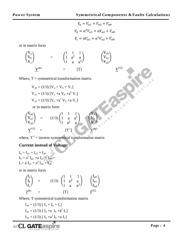
or in matrix form
=
= [T]
Where, T = symmetrical transformation matrix
Va0 = (1/3) [Va + Vb + Vc]
Va1 = (1/3) [Va +a Vb +a2 Vc]
Va2 = (1/3) [Va +a2 Vb +a Vc]
or in matrix form
= (1/3)
= [T-1]
where, T-1 = inverse symmetrical transformation matrix
Current instead of Voltage:
Ia = Ia1 + Ia2 + Ia0 Ib = a2 +a Ia2 + Ia0 Ic= a Ia1 + a2 Ia2 + Ia0
or in matrix form
= (1/3)
= [T]
Where, T symmetrical transformation matrix Ia0 = (1/3) [ Ia + Ib + Ic] Ia1 = (1/3) [ Ia +a Ib +a2 Ic
I]
a2 = (1/3) [ Ia +a2 Ib +a Ic]

Power System Symmetrical Components & Faults Calculations
Page : 5
or in matrix form
= (1/3)
= [T-1]
where, T-1 = inverse symmetrical transformation matrix Average 3 – phase power in Terms of Symmetrical Components: P = 3 [|Va0 |Ia0 | + |Va1| Ia1 | +|Va2 |Ia2 | ]
Impedance:
= [Zabc]
[T] = [Zabc] [T]
= [T-1] [Zabc] [T]
= [T-1] [Zabc] [T] (since Z012 = / )
[Zabc] =
& are self & mutual impedances
[Z012] =
Sequence Impedance and Networks: The impedance of a circuit when positive sequence currents alone are flowing is called the impedance to positive sequence current. Similarly, when only negative sequence currents are present, the impedance is called the impedance to negative sequence current. When only zero sequence currents are present, the impedance is called the impedance to zero sequence current.
Let Z a, Z b, Z c, & Zn are three phase impedances and neutral impedance
Za0 = 1/3 (Za + Zb + Zc) zero sequence
Za1 = 1/3 (Za +aZ b +a2 Zc) positive sequence
Za2 = 1/3 (Za +a2Zb +aZc) negative sequence

Power System Symmetrical Components & Faults Calculations
Page : 6
3.2 Sequence N/Ws of a synchronous Generator: 3.2.1 Positive sequence Network: The positive sequence network of a synchronous generator is a balanced and symmetrical three phase network with positive sequence generated voltages (Ea1, Eb1, Ec1 ) in the three phase, symmetrical three phase star impedance Z, in each phase and positive sequence currents (Ia1, Ib1, Ic1
Fig. 3.2
The three phase system can be replaced by a single phase network as shown in the below:
) flowing in the three phase of shown in the below figure.
Fig. 3.3
The equation of the positive sequence network is Va1 = Ea1 –Ia1. Z
Ia1
1
Ea1
Z1
~ Va1
+
-
‘E’ for the Generated voltage.
‘V’ for the Terminal voltage.
+
Eb1 EC1
Ea1
IC1
Z1 Z1
Ia1
Z1
+
Ib1
- -
-
+
~
~
~

Power System Symmetrical Components & Faults Calculations
Page : 7
3.2.2 Negative sequence network: In any general synchronous generator which is designed to generate, balanced voltages the negative sequence generated voltages are always zero. The negative network containing negative sequence impedance Z2
Fig. 3.4
The three phase network can be replaced by a single – phase network as shown in the below figure.
in each phase and negative sequence currents flowing through these carrying negative sequence voltage drops as shown below figure.
Fig. 3.5
The equation for the negative sequence network is Va2 = - Ia2.Z
3.2.3 Zero sequence Network:
2
The equation for the zero sequence network is Va0 = - Ia0 Z0
Z2
Va2
Ia2
Ia2
Z2
Z2
N
Ib2
Ic2
Z2
Power System Symmetrical Components & Faults Calculations
Page : 8
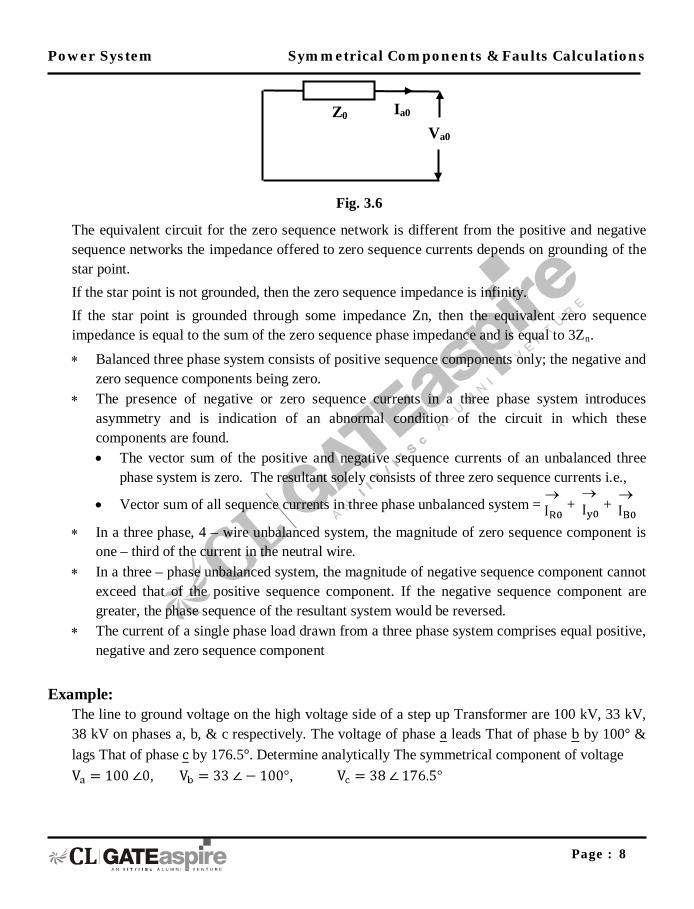
Fig. 3.6
The equivalent circuit for the zero sequence network is different from the positive and negative sequence networks the impedance offered to zero sequence currents depends on grounding of the star point. If the star point is not grounded, then the zero sequence impedance is infinity. If the star point is grounded through some impedance Zn, then the equivalent zero sequence impedance is equal to the sum of the zero sequence phase impedance and is equal to 3Zn
∗ Balanced three phase system consists of positive sequence components only; the negative and zero sequence components being zero.
.
∗ The presence of negative or zero sequence currents in a three phase system introduces asymmetry and is indication of an abnormal condition of the circuit in which these components are found. • The vector sum of the positive and negative sequence currents of an unbalanced three
phase system is zero. The resultant solely consists of three zero sequence currents i.e.,
• Vector sum of all sequence currents in three phase unbalanced system = + +
∗ In a three phase, 4 – wire unbalanced system, the magnitude of zero sequence component is one – third of the current in the neutral wire.
∗ In a three – phase unbalanced system, the magnitude of negative sequence component cannot exceed that of the positive sequence component. If the negative sequence component are greater, the phase sequence of the resultant system would be reversed.
∗ The current of a single phase load drawn from a three phase system comprises equal positive, negative and zero sequence component
Example:
The line to ground voltage on the high voltage side of a step up Transformer are 100 kV, 33 kV, 38 kV on phases a, b, & c respectively. The voltage of phase leads That of phase by 100° & lags That of phase by 176.5°. Determine analytically The symmetrical component of voltage
, ,
Z0
Va0
Ia0

Power System Symmetrical Components & Faults Calculations
Page : 9
Solution:
3.3 FAULT CALCULATIONS:
Faults can be classified as two types: 1. Series faults 2. Shunt faults
∗ Shunt faults are characterized by increase in current and decrease in voltage, frequency and power factor.
∗ Series faults are characterized by decrease in current and increase in voltage, frequency and power factor.
The series faults are classified as 1. One open conductor fault 2. Two open conductors fault The shunt type of fault are classified as: 1. Single line to ground fault 2. Line to Line fault 3. Double line to Ground fault 4. Three phase fault
∗ The first three faults are the unsymmetrical faults. ∗ The three phase fault is symmetrical faults. ∗ Severity & occurrence of Faults:

Power System Symmetrical Components & Faults Calculations
Page : 10
Fig. 3.7
Fault Severity Occurrence 1) 3-∅ (LLL,LLLG) Severe 5% 2) Phase to phase ground (LLG) Severe 10% 3) Phase to phase fault (LL) Less Severe 15% 4) Single line to ground Faults (LG) Very less 70%
* 1 cause of short circuit → insulation failure.
• Overvoltage caused by lightning or switching surge. • Insulation contamination → salt spray, pollution. • Mechanical causes → overheating, abrasion.
3.3.1 Faults on T.L.
• Most common – lines are exposed to elements of nature 60 – 70% lightning stroke → over voltage causes insulation to flash over
• Line to ground short circuit or line to line s.c. • High winds → topple tower, tree falls on line. • Winds an ice loading → mechanical failure of insulation. • For, salt spray, dirty insulation → conduction path → insulation failure.
S. C. other elements. Cabels (10 – 15%), C.B. (10 – 12%) generator, motor, X-mer (10 – 15%) → much less common → over loading for extended periods → deterioration of insulation
power transfer
power Faults
Time
3-∅
slg II
IIg

Power System Symmetrical Components & Faults Calculations
Page : 11
3.3.2 Voltage of the Neutral:
The potential of the neutral when it is grounded through some impedance or is isolated, will be at ground potential unbalanced conditions such as unsymmetrical faults. The potential of the neutral is given as Vn =In Zn where Zn is the neutral grounding impedance and In is neutral current. Here negative sign is used as the current flow from the ground to the neutral of the system and potential of the neutral is lower than the ground. For a 3- phase system, In = Ia +Ib +Ic
= (Ia1 + Ia2 + Ia0) + ( Ia1 +aIa2 Ia0) + (a Ia1 + a2 Ia2 + Ia0) = Ia1 (1+a+a2) + Ia2 (1+a+a2) +3Ia0
= 3Ia0 ∴ Vn = -3Ia0 Z
3.3.3 Single Line to Ground Fault:
n Since the positive sequence and negative sequence components of currents through the neutral are absent, the drops due to these currents are also zero.
1. Most frequently occurring fault. 2. Usually assumed the fault on phase – a for analysis purpose, phase – b and phase – are
healthy. The boundary conditions are a) Va
b) I = 0 ……….(1)
b
c) I = 0 ……….(2)
c = 0 ……….(3)
Power System Symmetrical Components & Faults Calculations
Page : 12
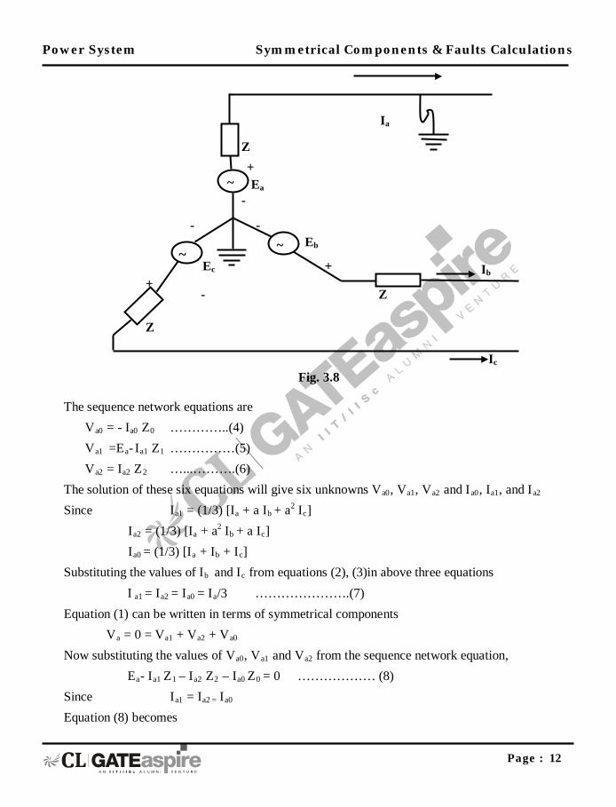
Fig. 3.8
The sequence network equations are Va0 = - Ia0 Z0 …………..(4) Va1 =Ea- Ia1 Z1 ……………(5) Va2 = Ia2 Z2 …...……….(6) The solution of these six equations will give six unknowns Va0, Va1, Va2 and Ia0, Ia1, and Ia2
Since Ia1 = (1/3) [Ia + a Ib + a2 Ic]
Ia2 = (1/3) [Ia + a2 Ib + a Ic]
Ia0 = (1/3) [Ia + Ib + Ic] Substituting the values of Ib and Ic from equations (2), (3)in above three equations
I a1 = Ia2 = Ia0 = Ia/3 ………………….(7) Equation (1) can be written in terms of symmetrical components
Va = 0 = Va1 + Va2 + Va0
Now substituting the values of Va0, Va1 and Va2 from the sequence network equation, Ea- Ia1 Z1 – Ia2 Z2 – Ia0 Z0 = 0 ……………… (8) Since Ia1 = Ia2 = Ia0 Equation (8) becomes
Ia
+
Ic
Ib Ec
Z
Z
+
~
-
- -
-
Ea
~
~
Z
Eb
+

Power System Symmetrical Components & Faults Calculations
Page : 13
Ea – Ia1 Z1 – Ia1 Z2- Ia1Z0 =0
Ia1 =
If = Ia = Ia1 + Ia2 + Ia0 ; and +ve, ve and zero sequence networks are connected in series.
If =
single Line of Ground fault with Zf :
Ia1
Fig. 3.9
Conclusion:
=
1. The three sequence networks are connected in series. 2. If the neutral of the generator is not grounded, the Zero network is open circuited.
Line to Line Fault
The line to line fault takes place on phases ‘b’ and ‘c’ The boundary conditions are Ia = 0 …………. (1) Ib + Ic = 0 …………. (2) Vb = Vc ...........(3)
Z1 Ia1
Va1
Va2
Va0
Ia2
Ia0
Z2
Z0
~

Power System Symmetrical Components & Faults Calculations
Page : 14
Fig. 3.10
The sequence network equations are Va0 = -Ia0 Z0 …………….. (4) Va1 = Ea = Ia1 Z1 ………………(5) Va2 = - Ia2 Z2 ………………(6) The solution of these six equations will give six unknowns Va0, Va1, Va2, and Iao, Ia1and Ia2
Since Ia1 = (1/3) [Ia + a Ib + a2 Ic] Ia = (1/3) [Ia + a2 Ib + a Ic] Ia1 = (1/3) [Ia + Ib + Ic] Substituting the values of Ia, Ib and Ic from equations in above three equations Ia1 = (1/3) [0 +a Ib - a2 Ib] = (1/3) [a- a2] Ib
Ia2 = (1/3) [0 +a2 Ib - a Ib] = (1/3) [ a2 - a] Ib
Ia0 = (1/3) [0 + Ib - Ib] Ia0 = 0 Which means for a line to line fault the zero sequence component of current is absent and positive sequence component of current is equal in magnitude but opposite in phase to negative sequence component of current, i.e.,
Ia
Ic
b EC
Ib Z
Z
Ea
Eb
a
Z
C

Power System Symmetrical Components & Faults Calculations
Page : 15
Fig. 3.11
Ia1 = -Ia2 …………… (7) Since Vb = a2Va1 + aVa2 + Va0 ………….. (8) VC = aVa1 + a2Va2 + Va0 …………..(9) Substituting the equations (8) and (9) equations (3)
a2Va1 + aVa2 + Va0 = aVa1 + a2Va2Va0
∴ Va1 = Va2 …………(10) i.e., positive sequence component of voltage equals the negative sequence component of voltage. This also means that the two sequence networks are connected in opposition. Now making use of the sequence network equation and the equation (10) ∴ Va1 = Va2.
Ea - Ia1 Z1 = -Ia2 Z2 = Ia1 Z2
Ia1 =
If = Ib = - Ic = a2Ia1 + aIa2 + Ia0 (Ia2 = - Ia1, Ia0 =0)
= I
1. The connection of sequence currents are connected in parallel.
a1
=
Conclusion:
2. The phase difference between Ia1 and Ia2 for line – to – line fault should be 180° (Ia1 = Ia2). Line to Line fault with Zf
Ia1 =
Double Line to Ground Fault: Here sequence networks are connected in parallel.
Va1 Va2
Ia1 Ia2 Z2 Z1
Ea

Power System Symmetrical Components & Faults Calculations
Page : 16
Double line to ground fault takes place on phases ‘b’ and ‘c’ The boundary conditions are Ia = 0 ……………….(1) Vb = 0 ……………….(2) Vc = 0 ……………….(3) The sequence network equations are Va0 = -Ia0 Z0 ……….(4) Va1 = Ea – Ia1 Z1 ……….(5) Va2 = -Ia2 Z2
Fig. 3.12
The solution of these six equations will give six unknowns V
..........(6)
a0, Va1, Va2 and Ia0, Ia1 and Ia2. Since Va0 = (1/3) [Va + Vb + Vc] Va1 = (1/3) [Va + aVb + a2 Vc] Va2 = (1/3) [Va + a2Vb + a Vc] Using above three equations and substituting for Va, Vb and Vc from the equation (2) and (3) Va0 = (1/3) [Va + 0 + 0 ] = Va/3 Va1 = (1/3) [Va +a. 0 +a2. 0 ] = Va
Ea
/3
Ia
Z
Ec
Z
C b
Z
Eb
Ic
Ib
+

Power System Symmetrical Components & Faults Calculations
Page : 17
Va2 = (1/3) [Va +a2. 0 + a.0 ] = Va/3 Va0 = Va1 = Va2 …………….(7) Using this relation of voltages and substituting in the sequence network equations Va0 = Va1 Ia0Z0 = Ea – Ia1 Z1
Ia0 = ………..(8)
Similarly Va2 = Va1 Ia2Z2 = Ea – Ia1 Z1
I a2 = ……….(9)
Now from equation (1) Ia = Ia1 + Ia2+Ia0
Fig. 3.13
Substituting values of I
=0
a2 and Ia0 from the equation(9) and (8)
Ia1 = = 0
Therefore Ia1=
If =Ib + Ic = 3 Ia0
Ia0 = -Ia1
If = -3 Ia1
-
Ea
+ Z1
Ia1
+
Va1
- -
Va2 Z2
Ia2 Ia0
Z0
+

Power System Symmetrical Components & Faults Calculations
Page : 18
Conclusion:
• Zero sequence and negative sequence networks are parallel and this is in series to the positive sequence.
Double line to ground fault with Zf
Ia1
3.4 Three Phase Fault
=
The boundary conditions are Ia + Ib + Ic = 0 Va = Vb =Vc
Ia is taken as reference Ib = a2 Ia and Ic = aI
Fig. 3.14
I
a
a1 =1/3 (Ia + a Ib + a2. Ic) and substituting the values of Ib and Ic
Ia1 = 1/3 (Ia + a. a2 Ia + a2 a Ia) Ia1= Ia Ia2 = 1/3 (Ia + a2 Ib + a Ic) = 1/3 (Ia + a4 Ib + a2 Ic) = 1/3 (Ia + a Ia + a2 Ic)
Ia
Ic
b
ECZ
Ib
Ea
Eb
a
Z
C
Z
Power System Symmetrical Components & Faults Calculations
Page : 19
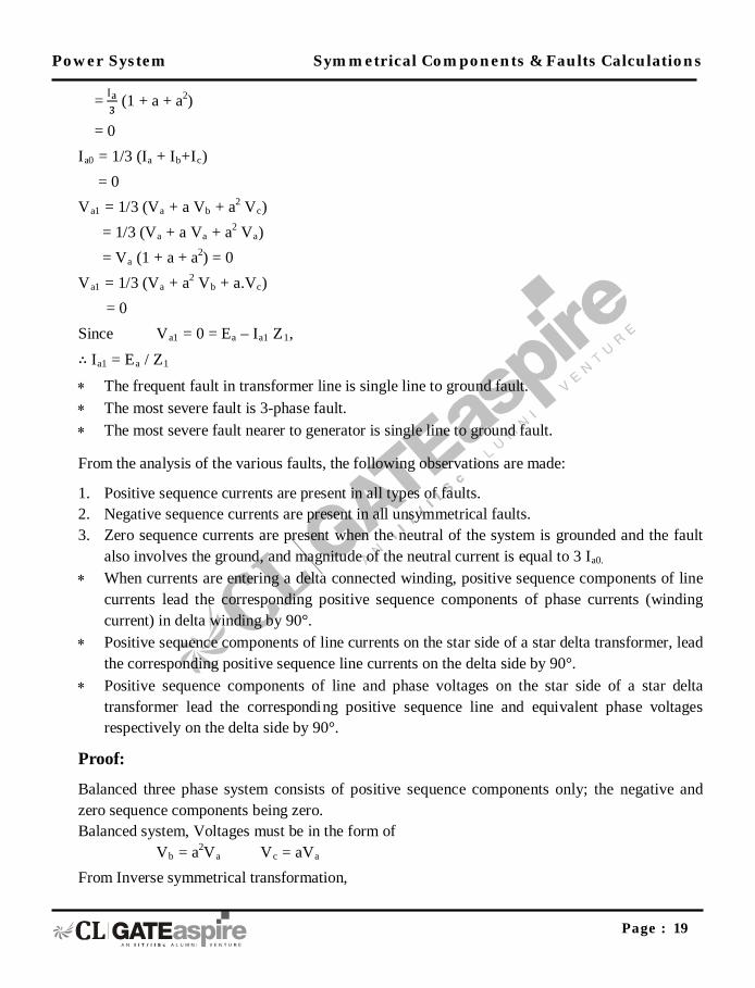
= (1 + a + a2)
= 0 Ia0 = 1/3 (Ia + Ib+Ic) = 0 Va1 = 1/3 (Va + a Vb + a2 Vc) = 1/3 (Va + a Va + a2 Va) = Va (1 + a + a2) = 0 Va1 = 1/3 (Va + a2 Vb + a.Vc) = 0 Since Va1 = 0 = Ea – Ia1 Z1, ∴ Ia1 = Ea / Z
∗ The frequent fault in transformer line is single line to ground fault. 1
∗ The most severe fault is 3-phase fault. ∗ The most severe fault nearer to generator is single line to ground fault.
From the analysis of the various faults, the following observations are made:
1. Positive sequence currents are present in all types of faults. 2. Negative sequence currents are present in all unsymmetrical faults. 3. Zero sequence currents are present when the neutral of the system is grounded and the fault
also involves the ground, and magnitude of the neutral current is equal to 3 Ia0.
∗ When currents are entering a delta connected winding, positive sequence components of line currents lead the corresponding positive sequence components of phase currents (winding current) in delta winding by 90°.
∗ Positive sequence components of line currents on the star side of a star delta transformer, lead the corresponding positive sequence line currents on the delta side by 90°.
∗ Positive sequence components of line and phase voltages on the star side of a star delta transformer lead the corresponding positive sequence line and equivalent phase voltages respectively on the delta side by 90°.
Proof:
Balanced three phase system consists of positive sequence components only; the negative and zero sequence components being zero. Balanced system, Voltages must be in the form of Vb = a2Va Vc = aVa From Inverse symmetrical transformation,

Power System Symmetrical Components & Faults Calculations
Page : 20
V012 = [T-1] Vabc
= (1/3)
= (1/3)
= (1/3) Va
= 1/3 Va ∴ 1 + a + a2 = 0
a3 = 1, a4 = a3 . a = a
= So for balanced 3 – ϕ system, Va0 = Va2 = 0; Va1 =V
1. Load bus:
a
Load Flow
* Load cannot be same for all time in the system. The power flow idea is to find out the voltage at different bus bar, sub - station, node point & the flow of power on these lines, with given constraints and specifications.
Types of Buses:
In this type of bus, and are known. The unknowns are | | and .
2. Slack Bus Reference Bus Swing Bus:- This bus is a special type of bus. Here real and reactive powers are not specified only and
are known.
3. Generator Voltage control PV Bus:- In this type of bus and are known. and are not known.
Power System Network

Power System Symmetrical Components & Faults Calculations
Page : 21
Fig. 3.15
L → Load G → Generator [Those bus who has self generator are called generated bus bar.] [Who’s don’t have generator called load bus bar.]
Fig. 3.16
to bus m to bus s
to bus
∠
gen Load
1
2
3
4 5
generator
bus burs
~ ~
~

Power System Symmetrical Components & Faults Calculations
Page : 22
Where injected power (real) in to bus. & injected (reactive) power into bus. For load bus So we can write
(i) (ii)
On the behalf of equation (i) and (ii) load bus are drawing the power.
Example:
Fig. 3.17
Static analysis of Power Network. Mathematical model of the Network T.L. – nominal π model. Bus power injection –
. .
But Admittance matrix Taking small example
to bus m
Bus K
to bus J
to bus i

Power System Symmetrical Components & Faults Calculations
Page : 23
Fig. 3.18
equivalent π model.
Fig. 3.19
Shunt admittance
1
2
3

Power System Symmetrical Components & Faults Calculations
Page : 24
Now power equation converting in current equation. So we can write equation.
→
self admittance. (Driving point admittance) → transfer admittance or mutual adce.
1. formatting is so easy & & Z matrix comp. 2. is symmetric matrix
matrix is sparse matrix. (Sparse means most of the elements of matrix are zero) Because there are 90% elements are zero.
3. Dimension of is (N × N) → N = No. of bus
Power Flow Equation
. , k, n = 1, 2, - - - - - N.

Power System Symmetrical Components & Faults Calculations
Page : 25
Characteristics of power flow equation Power flow equation are algebraic – static system _____________________nonlinear – Iterative solution Relate P, Q in terms of V, δ & elements
There are two methods to solve these non –linear equations: 1. Newton Raphson method 2. Gauss – Seidal method Newton Raphson (N.R.) method has got quadratic convergence and is fast as compared to Gauss – Seidal and always converge. But N.R. method requires more time per iteration. Gauss – Seidal has got linear convergence, convergence is affected by choice of slack bus and the presence of sense capacitor.
Example: Assume a three – phase system with a sustained supply voltage of 2,300 volts from line to neutral and with line impedance and . Compute the magnitude of fault current for a single line to ground fault at the end of the line.
Solution: Supply voltage = 2300 V line/neutral
For a single line to ground fault at “a” in Figure below.
a
b
c

Power System Symmetrical Components & Faults Calculations
Page : 26
then
where is prefault voltage
Also