Embed Size (px)
Citation preview

Symmetric-Extension-Compatible Reversible
Integer-To-Integer Wavelet Transforms
Michael D. Adams∗, Member, IEEE and Rabab K. Ward, Fellow, IEEE
Abstract
Symmetric extension is explored as a means for constructing nonexpansive reversible integer-to-integer (ITI)
wavelet transforms for finite-length signals. Two families of reversible ITI wavelet transforms are introduced, and
their constituent transforms are shown to be compatible with symmetric extension. One of these families is then
studied in detail, and several interesting results concerning its member transforms are presented. In addition, some
new reversible ITI structures are derived that are useful in conjunction with techniques like symmetric extension.
Lastly, the relationship between symmetric extension and per-lifting-step extension is explored, and some new
results are obtained in this regard.
EDICS Category: 3-COMP (Signal Representation and Compression)
∗Corresponding author:
Michael D. Adams
Dept. of Electrical and Computer Engineering
University of Victoria
P.O. Box 3055 STN CSC
Victoria, BC, V8W 3P6, Canada
Tel: 1-250-721-6025, Fax: 1-250-721-6052
E-mail: [email protected]
Other author:
Rabab K. Ward
Dept. of Electrical and Computer Engineering
University of British Columbia
2356 Main Mall
Vancouver, BC, V6T 1Z4, Canada
Tel: 1-604-822-6894, Fax: 1-604-822-9013
E-mail: [email protected]

1
Symmetric-Extension-Compatible Reversible
Integer-To-Integer Wavelet Transforms
Michael D. Adams, Member, IEEE, and Rabab K. Ward, Fellow, IEEE
Abstract
Symmetric extension is explored as a means for constructing nonexpansive reversible integer-to-integer (ITI)
wavelet transforms for finite-length signals. Two families of reversible ITI wavelet transforms are introduced, and
their constituent transforms are shown to be compatible with symmetric extension. One of these families is then
studied in detail, and several interesting results concerning its member transforms are presented. In addition, some
new reversible ITI structures are derived that are useful in conjunction with techniques like symmetric extension.
Lastly, the relationship between symmetric extension and per-lifting-step extension is explored, and some new
results are obtained in this regard.
I. INTRODUCTION
During the last several years, reversible integer-to-integer (ITI) wavelet transforms [1–3] have become
a popular tool for use in signal coding applications, especially image compression (e.g., [4–9]). Such
transforms are invertible in finite-precision arithmetic (i.e., reversible), map integers to integers, and serve
as nonlinear approximations to conventional (i.e., linear) wavelet transforms [10]. Frequently, reversible
ITI wavelet transforms are defined in such a way as to operate on signals of infinite length. In practice,
however, we almost invariably deal with finite-length signals. Therefore, we require some means for
adapting reversible ITI wavelet transforms to handle such signals. In essence, we must address the well-
known boundary problem that can arise when any finite-length signal is filtered (as filtering is part of
the wavelet transform process). Furthermore, in signal coding applications, we almost always want to
employ a transform that is nonexpansive (i.e., maps a signal of length N to a signal of length no greater
than N). Therefore, we seek a solution to the boundary problem that yields nonexpansive transforms.
A similar boundary problem also arises in the case of conventional wavelet transforms, and numerous
solutions have been proposed for this case over the years. Unfortunately, many of these methods are not
easily applied or even useful in the reversible ITI case, as this case is complicated by both the nonlinear
nature of the transforms involved and the requirement that reversibility be maintained.
In this manuscript, we explore symmetric extension [11, 12] as a means for constructing nonexpansive
This work was supported by the Natural Sciences and Engineering Research Council of Canada.
January 23, 2003 DRAFT

2
reversible ITI wavelet transforms. Although commonly used in the case of conventional wavelet trans-
forms, symmetric extension is more difficult to apply in the reversible ITI case. In our work, we explain
how this method can be utilized in the latter case. In addition, we consider the relationship between
symmetric extension and another extension method which we refer to as per-lifting-step extension.
The remainder of this manuscript is structured as follows. We begin, in Section II, by presenting the
basic notation and terminology used herein, and then proceed to discuss a few fundamentals of reversible
ITI wavelet transforms in Section III. Next, our attention shifts to symmetric extension. In Section IV,
we introduce this particular method and explain the conditions that must be satisfied in order for it to be
applicable. In Section V, we present two families of reversible ITI wavelet transforms, and then proceed
to demonstrate, in Section VI, that the transforms from these families are compatible with symmetric
extension (i.e., can be used with symmetric extension in order to handle finite-length signals in a nonex-
pansive manner). In Section VII, we study one of the two transform families more closely, and present
several interesting results concerning its constituent transforms. Afterwards, Section VIII proposes some
new reversible ITI structures that are useful in conjunction with techniques like symmetric extension. In
Section IX, we briefly introduce per-lifting-step (PLS) extension, and consider the relationship between
PLS extension and symmetric extension. Finally, we conclude, in Section X, with a summary of our
results and some closing remarks.
One particularly novel aspect of our work is our careful consideration of rounding operators and their
properties. Our close attention to rounding operators has led to many new insights, allowing us to develop
some entirely new ideas as well as extend some previously proposed ones. For example, through such
insights, we were able to extend a previously existing transform family in order to yield one of the two
families presented in this manuscript. This was possible, in part, due to a better understanding of why
the base filter bank for the original family preserves certain signal symmetries. Also, we were able to
derive several new reversible ITI structures (which are useful in conjunction with symmetric extension),
and provide an example of a transform utilizing these structures.
II. NOTATION AND OTHER PRELIMINARIES
Before proceeding further, a short digression concerning the notation used in this manuscript is ap-
propriate. The symbols Z and R denote the sets of integer and real numbers, respectively. Matrix and
vector quantities are indicated using bold type. The symbols IN and JN denote the N ×N identity and
anti-identity matrices, respectively, where the subscript N may be omitted when clear from the context.
January 23, 2003 DRAFT

3
In the case of matrix multiplication, we define the product notation as follows:
∏Ni=M Ai
4=
ANAN−1 · · ·AM+1AM for N ≥ M
I otherwise.
For a Laurent polynomial P(z), we denote the degree of P(z) as degP(z), and define this quantity as
follows. In the case that P(z) has the form P(z) = ∑Ni=M piz−i where N ≥ M, pM 6= 0, and pN 6= 0 (i.e.,
P(z) 6≡ 0), degP(z)4= N −M. In the case that P(z) is the zero polynomial (i.e., P(z) ≡ 0), we define
degP(z)4= −∞. Thus, for any two Laurent polynomials, A(z) and B(z), we have that deg(A(z)B(z)) =
degA(z)+degB(z).
The notation Z and Z−1 are used to denote the forward and inverse Z transform operators, respectively.
A signal x[n] is said to have symmetry if it satisfies
x[n] = (−1)Sx[2C−n] for all n ∈ Z,
for some choice of symmetry center C and symmetry type S, where C is an integer multiple of 12 and
S ∈ {0,1}. If S is zero, x[n] is said to be symmetric; if S is one, x[n] is said to be antisymmetric.
For α ∈ R, the notation bαc denotes the largest integer not more than α (i.e., the floor function), and
the notation dαe denotes the smallest integer not less than α (i.e., the ceiling function). The biased floor,
biased ceiling, truncation, biased truncation, and rounding-away-from-zero (RAFZ) functions are defined,
respectively, as
bfloorα 4=⌊
α+ 12
⌋
, bceilα 4= dα− 1
2e,
truncα 4=
bαc for α ≥ 0
dαe for α < 0,
btruncα 4=
bfloorα for α ≥ 0
bceilα for α < 0,
and (1)
rafzα 4=
dαe for α ≥ 0
bαc for α < 0,(2)
where α ∈ R. One can show that, for all α ∈ R, the following relationships hold:
dαe = −b−αc and (3)
bceilα =
bfloor(α)−1 if α is an odd integer multiple of 12
bfloorα otherwise.(4)
January 23, 2003 DRAFT
4
(For a proof of the latter, see [3].) The mod and signum functions are defined, respectively, as
mod(x,y)4= x− ybx/yc and sgnα 4
=
1 for α > 0
0 for α = 0
−1 for α < 0,
where x,y∈Z and α ∈R. In passing, we note that the mod function simply computes the remainder when
x is divided by y, with division being defined in such a way that the remainder is always nonnegative.
From (3) and the definition of the mod function, we trivially have the identities
bx/yc = x−mod(x,y)y and dx/ye = x+mod(−x,y)
y for x,y ∈ Z and y 6= 0. (5)
A rounding operator Q is said to be integer-bias invariant if
Q(α+ x) = Q(α)+ x for all α ∈ R and all x ∈ Z.
Similarly, a rounding operator Q is said to be odd if
Q(α) = −Q(−α) for all α ∈ R.
One can show that a rounding operator cannot be both odd and integer-bias invariant [13]. In passing,
we note that the floor, biased floor, ceiling, and biased ceiling functions are integer-bias invariant (but not
odd), while the truncation, biased truncation, and RAFZ functions are odd (but not integer-bias invariant).
All rounding operators considered in this manuscript are tacitly assumed to be memoryless, time invariant,
and leave integer values unchanged. Any (reasonable) rounding operator will preserve signal symmetry
(but not necessarily signal antisymmetry), while any odd rounding operator will preserve both signal
symmetry and antisymmetry.
III. REVERSIBLE ITI WAVELET TRANSFORMS
The reversible ITI wavelet transforms considered in this manuscript are based on the lifting frame-
work [1, 2, 14, 15] and are associated with a uniformly-maximally-decimated (UMD) filter bank of the
form shown in Fig. 1. In the figure, the analysis and synthesis polyphase filtering networks each consist
of 2λ lifting-step filters {Ak}2λ−1k=0 and 2λ rounding operators {Qk}
2λ−1k=0 . In the absence of the rounding
operators (i.e., the {Qk}), the system in Fig. 1 becomes a linear system, which corresponds to a con-
ventional wavelet transform. Furthermore, this linear system can be realized using a UMD filter bank in
its canonical form as shown in Fig. 2, where the {Hk}1k=0 and {Fk}
1k=0 are analysis and synthesis filters,
respectively. To convert a system of the form shown in Fig. 2 to the form shown in Fig. 1, one needs to
solve the matrix factorization problem treated in [16, 17].
January 23, 2003 DRAFT

5
↓2
↓2
j+
j+
z
j+
j+
A0(z)
Q0
Q1
A1(z)
6
6
6
-
??
?
?
-
-
--
?
-
- - 6
6
6
- -
-
?
?
?-
-
-
· · ·
· · ·
· · ·
· · ·
u0[n]
Q2λ−2
Q2λ−1
A2λ−1(z)
x[n] y0[n]
y1[n]
A2λ−2(z)
u1[n] u2[n] u2λ−2[n] u2λ−1[n]
v0[n] v1[n] v2[n] v2λ−2[n]
(a)
j+
j+
j+
j+
↑2
↑2
j+
z−1
A0(z)Q1
A1(z) Q0
?- - -
- 6?
-- - - -6
- -
6?
-
6
6
- --
6
?
6 6? ?Q2λ−1 A2λ−2(z)
A2λ−1(z) Q2λ−2 · · ·
· · ·
· · ·
· · ·y1[n]
y0[n] u0[n] x[n]
− −
v0[n]
− −
v1[n]v2[n]
u1[n]u2[n]u2λ−2[n]u2λ−1[n]
v2λ−2[n]
(b)
Fig. 1. Lifting realization of a reversible ITI wavelet transform.
(a) Analysis filter bank and (b) synthesis filter bank.
↓2
↓2
H1(z)
H0(z)- -
?
-
-
-
-
x[n] y0[n]
y1[n]
(a)
↑2 j+
↑2
F0(z)
F1(z)
-
- - -
- - -y0[n]
y1[n]
x[n]
(b)
Fig. 2. The canonical realization of a con-
ventional wavelet transform. (a) Analysis
filter bank and (b) synthesis filter bank.
Perhaps it is worth nothing that, for the purposes of this manuscript, the term “wavelet transform” is
used to mean a transform associated with an octave-band filter bank, but without any implied constraints
on the underlying basis functions. This definition is somewhat more relaxed than the formal mathematical
definition of wavelet systems (which, for example, imposes constraints on the smoothness of the underly-
ing basis functions). Since our work is equally applicable regardless of whether the looser or more formal
definition is employed, we shall not dwell on this matter further.
IV. SYMMETRIC EXTENSION
In the case of conventional wavelet transforms, a popular technique for handing finite-length signals in
a nonexpansive manner is symmetric extension. The use of symmetric extension was first proposed by
Smith and Eddins [12], and subsequently received considerable attention in the literature (e.g., [11, 18–
24]). With this technique, a signal is extended so that it is both symmetric and periodic. Then, both the
symmetry and periodicity properties are exploited in order to obtain a transform that is nonexpansive.
Consider the UMD filter bank shown in Fig. 2 which computes a conventional wavelet transform. Sup-
pose that we have a finite-length signal x[n] defined for n = 0,1, . . . ,N−1. We then choose x[n], the input
to the analysis filter bank, as a symmetric extension of x[n]. Thus, the period of x[n] is (approximately)
January 23, 2003 DRAFT

6
2N. In order to be able to handle finite-length signals in a nonexpansive manner, symmetric extension
must be employed with a transform that preserves signal symmetry. That is, the transform must be such
that an appropriately chosen symmetric input signal x[n] yields symmetric/antisymmetric subband signals
{yk[n]}1k=0. Therefore, each of the subband signals {yk[n]}1
k=0 is symmetric/antisymmetric with a period
of (approximately) N. Since each of the subband signals {yk[n]}1k=0 has symmetry, only (about) one half
of the samples of a single period are required to characterize the signal. In other words, we only need
(about) N2 samples from each subband signal, for a total of N
2 + N2 = N samples. Thus, a nonexpansive
transform is obtained.
As indicated above, symmetric extension requires a transform that preserves signal symmetry. Not
all conventional wavelet transforms satisfy this constraint. More importantly, even when a conventional
wavelet transform does preserve signal symmetry, a reversible ITI version of the same transform may
not (due to the addition of rounding operations). Therefore, applying the symmetric extension method in
the reversible ITI case is inherently more complicated. Fortunately, as we explain in this manuscript, it is
possible to construct reversible ITI wavelet transforms that are compatible with symmetric extension (i.e.,
satisfy the above symmetry preservation constraint). In fact, in the next section, we present two families
of such transforms.
V. TRANSFORM FAMILIES
In this manuscript, we consider two families of reversible ITI wavelet transforms that are compatible
with symmetric extension. Both are derived from the lifting-based parameterizations of linear-phase filter
banks presented in [25], and have the general form shown previously in Fig. 1.
Odd-Length Analysis/Synthesis Filter (OLASF) Family
The first family of reversible ITI wavelet transforms is associated with a linear-phase filter bank having
odd-length analysis/synthesis filters, and hence is referred to as the odd-length analysis/synthesis filter
(OLASF) family. For this family, the parameters of Fig. 1 are constrained as follows:
Ak(z) =
∑(Lk−2)/2i=0 ak,i(z−i + zi+1) for even k
∑(Lk−2)/2i=0 ak,i(z−i−1 + zi) for odd k,
(6)
for k = 0,1, . . . ,2λ− 1, where the {Lk}2λ−1k=0 are all even integers. The {Qk}
2λ−1k=0 can be chosen as any
arbitrary rounding operators. Without loss of generality, we assume that none of the {Ak(z)}2λ−2k=1 are
identically zero (i.e., only A0(z) and A2λ−1(z) may be identically zero). In passing, we note that the “odd-
length” qualifier in the name “OLASF” refers to the length of the corresponding analysis/synthesis filters
January 23, 2003 DRAFT

7
(i.e., the {Hk} and {Fk} in Fig. 2), not the lifting filters (i.e., the {Ak} above) which have even length.
One can show that any perfect-reconstruction (PR) linear-phase FIR filter bank with odd-length analy-
sis/synthesis filters has a corresponding OLASF parameterization, provided that the analysis and synthesis
filters are normalized appropriately (via a scaling and shift of their impulse responses). The proof is con-
structive by a matrix Euclidean algorithm (e.g., by using an algorithm based on that described in [16]).
Some well known members of the OLASF family that are useful for signal coding include the 5/3, 9/7-M,
5/11-A, 5/11-C, 13/7-T, 13/7-C, and 9/7-F transforms presented in [8].
Even-Length Analysis/Synthesis Filter (ELASF) Family
The second family of reversible ITI wavelet transforms is associated with a linear-phase filter bank
having even-length analysis/synthesis filters, and hence is referred to as the even-length analysis/synthesis
filter (ELASF) family. For this family, the parameters of Fig. 1 are constrained as follows:
Ak(z) =
−1 for k = 0
12 + A1(z) for k = 1
Ak(z) for k ≥ 2,
and (7a)
Qk is
integer-bias invariant for k = 1
odd for k ≥ 2 and k even
arbitrary for k ≥ 2 and k odd,
(7b)
for k = 0,1, . . . ,2λ−1, where
Ak(z) = ∑(Lk−1)/2i=1 ak,i(z−i − zi), (7c)
λ ≥ 1, and the {Lk}2λ−1k=1 are all odd integers. (The operator Q0 is simply chosen as the identity, since
the output of the filter A0 is always an integer.) Without loss of generality, we assume that none of
the {Ak(z)}2λ−2k=2 are identically zero (i.e., only A1(z) and A2λ−1(z) may be identically zero). In passing,
we note that the “even-length” qualifier in the name “ELASF” refers to the length of the corresponding
analysis/synthesis filters (i.e., the {Hk} and {Fk} in Fig. 2), not the lifting filters (i.e., the {Ak} above)
which have odd length.
The ELASF transform family is a generalization of ones commonly considered in the literature (e.g.,
[26]). Our proposed family is a generalization in two respects. First, in the case of transform families
with a similar structure, it is often suggested that the {Qk}2λ−1k=2 must all be chosen as odd functions. Such
a choice, however, is overly restrictive. The rounding operators {Qk}2λ−1k=2 only need to be chosen as odd
January 23, 2003 DRAFT
8
↓2
↓2
z
j+
j+ j+
j+
−1
Q1
12
-
?
?
-
?
?-
-
6
6
6-
6
6
6
-?
?
?--
- --
-
x[n]
A1(z)
Q′1 A2(z)
Q2
y1[n]
y0[n]
(a)
↓2
↓2
z
j+
j+
j+
12 + A1(z)
−1
Q1
-
?
?
-
?
?
-
6
6
6
-
-
--?
?
?- - -
x[n]
A2(z)
y0[n]
y1[n]
Q2
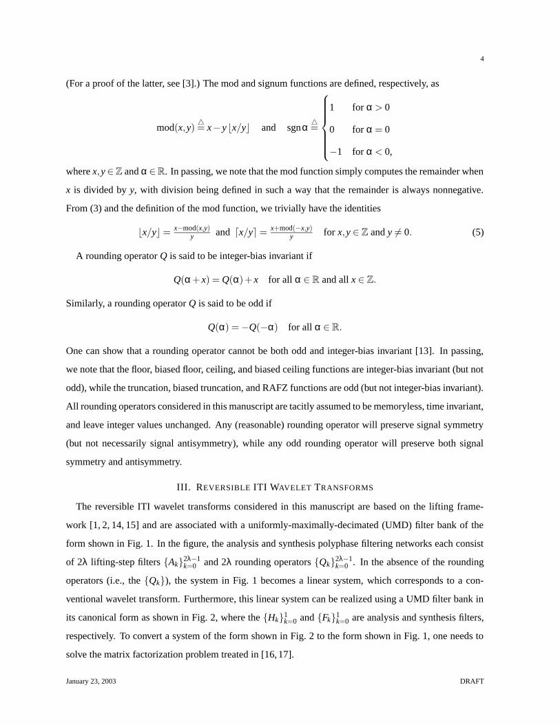
(b)Fig. 3. Two different reversible ITI approximations for the 6/14 transform. The analysis filter bank based on
the (a) commonly referenced parameterization and (b) our more general parameterization. A1(z) = − 116 (z− z−1),
A2(z) = 116
(
(z2 − z−2)−6(z− z−1))
, Q1 is integer-bias invariant, Q′1 is arbitrary, and Q2 is odd.
functions for even k. Second, and more fundamentally, the related families commonly considered in the
literature (e.g., as in [26]) are essentially a special case of our proposed family with A1(z) ≡ 0.
The additional flexibility afforded by the introduction of the A1(z) parameter has important practical
implications. In many cases, by using our more general parameterization, the number of lifting steps
can be reduced by one. By reducing the number of lifting steps, the number of rounding operations is
also decreased, leading to a reduction in rounding error. Consider, for example, the two ITI filter banks
shown in Fig. 3. One can easily verify that both filter banks approximate the same linear transform,
namely the one associated with the 6/14 transform [8] which is known to be effective for image coding
purposes. Both filter banks are reversible, as both employ lifting/ladder networks for polyphase filtering,
but due to the nonlinearities introduced by rounding, the two filter banks are not equivalent. Comparing
the filter banks of Figs. 3(a) and 3(b), we can see that the former has one more rounding operation than
the latter. For this reason, the filter bank in Fig. 3(b) will normally have better approximation properties
(i.e., smaller rounding error) than the filter bank of Fig. 3(a). Although not immediately obvious, like
the filter bank in Fig. 3(a), the filter bank in Fig. 3(b) is also compatible with the symmetric extension
method, as we will show in a later section.
Only a subset of all transforms associated with PR linear-phase FIR filter banks with even-length anal-
ysis/synthesis filters belong to the ELASF family. Moreover, this subset is quite small. In this work, we
consider only those transforms belonging to the ELASF family because our interest lies with transforms
that are compatible with symmetric extension. As we will demonstrate later, transforms in the ELASF
family are compatible with this method. It is not clear, however, how (or even if) the compatibility issue
can be handled in the more general even-length analysis/synthesis filter case. (For example, the associated
matrix factorization problem has been studied in [27], but the scheme presented therein does not gener-
January 23, 2003 DRAFT

9
ally yield transforms that are compatible with symmetric extension.) Notwithstanding the constrained
nature of the ELASF family, it still contains many practically useful transforms. Some well known mem-
bers of this family that are useful for signal coding include (minor variations on) the 2/6, 2/10, and 6/14
transforms discussed in [8] and the S transform [6].
Derivation of the Transform Families
In essence, the preceding families were derived by observing that if the forward polyphase transform
(i.e., shifting followed by downsampling) preserves symmetry and the subsequent lifting steps collectively
preserve symmetry, then the overall transform will also preserve symmetry and therefore be compatible
with symmetric extension. Fortunately, the forward polyphase transform does not pose much of a prob-
lem, as it is relatively easy to have this process preserve symmetry. The difficulty is in finding a general
set of lifting steps that collectively preserve symmetry. This is most easily achieved by requiring that
all/most of the lifting steps individually preserve symmetry. In turn, this is accomplished by choosing
all/most of the lifting step filters to have linear phase. The specifics of why this approach works will
become clear in the next section.
VI. COMPATIBILITY OF TRANSFORM FAMILIES WITH SYMMETRIC EXTENSION
In the previous section, we introduced the OLASF and ELASF families of reversible ITI wavelet trans-
forms. Now, we show that the transforms from these two families are compatible with symmetric exten-
sion (i.e., can be used with symmetric extension in order to handle finite-length signals in a nonexpansive
manner). Consider a filter bank of the form shown in Fig. 1 that is constrained to be of the OLASF
type as defined by (6) or ELASF type as defined by (7). Suppose that we are given a signal x[n] de-
fined for n = 0,1, . . . ,N − 1. By using symmetric extension, one can form a nonexpansive transform, as
demonstrated by the two propositions and accompanying proofs below.
Proposition 1 (Compatibility of the OLASF family with symmetric extension) Consider a filter bank
of the form shown in Fig. 1 that is constrained to be of the OLASF type as defined by (6). Suppose now
that we are given a signal x[n] defined for n = 0,1, . . . ,N −1. If we choose x[n], the input to the analysis
filter bank, as the symmetric extension of x[n] given by
x[n] = x[min(mod(n−K,2N −2),2N −2−mod(n−K,2N −2))], K ∈ Z (8)
(i.e., x[n] is defined such that x[n] = x[n + 2N − 2] and x[n] = x[2K − n] for all n ∈ Z), then 1) y0[n] is
completely characterized by its N0 samples at indices dK2 e,d
K2 e+ 1, . . . ,
⌊
K+N−12
⌋
; 2) y1[n] is completely
characterized by its N1 samples at indices dK−12 e,dK−1
2 e+ 1, . . . ,⌊
K+N−22
⌋
; and 3) N0 + N1 = N (i.e., the
January 23, 2003 DRAFT
10
transform is nonexpansive).
Proof: Consider the OLASF-type system associated with Fig. 1. Evidently, x[n] is (2N − 2)-
periodic and symmetric about K and K + N − 1 (with additional pairs of symmetry points following
from periodicity). From the properties of downsampling, one can show that u0[n] is (N − 1)-periodic
and symmetric about K2 and K+N−1
2 , and v0[n] is (N −1)-periodic and symmetric about K−12 and K+N−2
2 .
Consider now the first lifting step (associated with filter A0). Since, from (6), the filter A0 has a group
delay of − 12 and the rounding operator Q0 preserves signal symmetry, the adder (at the output of Q0)
is summing two (N − 1)-periodic symmetric signals with the same symmetry centers. Thus, the adder
output, v1[n], is also (N − 1)-periodic and symmetric with the same symmetry centers, namely K−12 and
K+N−22 . Consider now the second lifting step (associated with filter A1). Since, from (6), the filter A1
has a group delay of 12 and the rounding operator Q1 preserves signal symmetry, both adder inputs are
(N −1)-periodic symmetric signals with the same symmetry centers. Therefore, the adder output, u2[n],
must also be (N−1)-periodic and symmetric with the same symmetry centers, namely K2 and K+N−1
2 . By
repeating the above reasoning for each of the remaining lifting steps, we have that the {uk[n]}2λ−1k=0 and
y0[n] are all (N −1)-periodic and symmetric about K2 and K+N−1
2 . Likewise, the {vk[n]}2λ−2k=0 and y1[n] are
all (N −1)-periodic and symmetric about K−12 and K+N−2
2 .
By examining the form of the various signals, we can see that the {uk[n]}2λ−1k=0 and y0[n] are completely
characterized by the N0 samples at indices dK2 e,d
K2 e+1, . . . ,
⌊
K+N−12
⌋
, and the {vk[n]}2λ−2k=0 and y1[n] are
completely characterized by the N1 samples at indices dK−12 e,dK−1
2 e+1, . . . ,⌊
K+N−22
⌋
, where
N04=⌊
K+N−12
⌋
−dK2 e+1 and (9)
N14=⌊
K+N−22
⌋
−dK−12 e+1. (10)
Using (5), we can further simplify (9) and (10) to obtain
N0 =
N2 for even N
N+12 for odd N, even K
N−12 for odd N, odd K,
and N1 =
N2 for even N
N−12 for odd N, even K
N+12 for odd N, odd K.
(11)
Thus, from (11), we have that, regardless of the parities of K and N, N0 + N1 = N. In other words, the
total number of independent samples in the transformed signal is always equal to the number of samples
in the original signal, and the resulting transform is, therefore, nonexpansive.
Proposition 2 (Compatibility of the ELASF family with symmetric extension) Consider a filter bank
of the form shown in Fig. 1 that is constrained to be of the ELASF type as defined by (7). Suppose
January 23, 2003 DRAFT

11
?
-
-
-
6
6
6
--
-
-
?-
?
?
↓2
+j
−1z
↓2
j+
x[n]
12 + A1(z)
u2[n]
v2[n]
Q1
u1[n]
v0[n] v1[n]
u0[n]
Fig. 4. Base analysis filter bank for the ELASF family of transforms.
now that we are given a signal x[n] defined for n = 0,1, . . . ,N − 1. If we choose x[n], the input to the
analysis filter bank, as the symmetric extension of x[n] given by
x[n] = x[min(mod(n−K,2N),2N −1−mod(n−K,2N))], K ∈ Z (12)
(i.e., x[n] is defined such that x[n] = x[n + 2N] and x[n] = x[2K − 1− n] for all n ∈ Z), then 1) y0[n] is
completely characterized by its N0 samples at indices dK−12 e,dK−1
2 e+ 1, . . . ,⌊
K+N−12
⌋
; 2) y1[n] is com-
pletely characterized by its N1 samples at indices dK2 e,d
K2 e+ 1, . . . ,
⌊
K+N−22
⌋
; and 3) N0 + N1 = N (i.e.,
the transform is nonexpansive).
Proof: Consider a transform in the ELASF family. Such a transform is associated with the filter
bank shown in Fig. 1 having the corresponding parameters given by (7). The base part of the analysis filter
bank has the form shown in Fig. 4. Now, let us consider the linear version of this filter bank as depicted
in Fig. 5. This filter bank can be represented in canonical form as shown in Fig. 2, where the transfer
functions of the lowpass and highpass analysis filters are denoted as H0(z) and H1(z), respectively. Using
the noble identities [28], we can show that
H0(z) = 12(z+1)+(z−1)A1(z
2) and H1(z) = z−1. (13)
Due to the form of A1(z) in (7), it follows from (13) that the filter H0 has an impulse response symmetric
about − 12 . From (13), the filter H1 has an impulse response that is antisymmetric about − 1
2 . Consequently,
in Fig. 5, if x[n] is generated using (12), we have that u2[n] is N-periodic and symmetric about K−12 and
v2[n] is N-periodic and antisymmetric with the same symmetry center as u2[n]. Since u2[n] and v2[n] are
N-periodic, it follows that both signals must also have another symmetry center at K+N−12 .
Now, suppose that we round the lowpass subband output u2[n] in Fig. 5, so as to obtain the system
shown in Fig. 6. For any (reasonable) rounding function, this process will maintain signal symmetry.
Moreover, if the rounding operator Q is integer-bias invariant, we can equivalently move the rounding
operator to the input side of the adder, resulting in the system in Fig. 4 (where Q1 = Q). Consequently,
in the case of the system in Fig. 4, if the input x[n] has the form of (12), u2[n] must be N-periodic
January 23, 2003 DRAFT

12
-
-
?
-
-- -
6
6?
-
-
?
?
z
↓2
+j
−1
+j
↓2x[n]
12 + A1(z)
u2[n]
v2[n]v0[n] v1[n]
u0[n] u1[n]
Fig. 5. Linear version of the base analysis filter
bank for the ELASF family of transforms.
-
-
?
--
-- -
6
-
6?
-?
?
z
↓2
Q+j
−1
+j
↓2x[n]
12 + A1(z)
u2[n]
v2[n]
u0[n] u1[n]
v1[n]v0[n]
Fig. 6. Modified base analysis filter bank for the
ELASF family of transforms.
and symmetric about K−12 and K+N−1
2 , while v2[n] must be N-periodic and antisymmetric with the same
symmetry centers as u2[n].
Now, let us return to the system in Fig. 1. From above, we have that u2[n] is N-periodic and symmetric
about K−12 and K+N−1
2 , and v2[n] is N-periodic and antisymmetric with the same symmetry points as u2[n].
Consider now the third lifting step (associated with filter A2). Since, from (7), the filter A2 has a group
delay of zero, and the rounding operator Q2 preserves signal antisymmetry (since it is odd), the adder
(at the output of Q2) is summing two N-periodic antisymmetric signals with the same symmetry centers.
Thus, the adder output is also N-periodic and antisymmetric with the same symmetry centers. Consider
the fourth lifting step (associated with filter A3). Since, from (7), the filter A3 has a group delay of zero,
and the rounding operator Q3 preserves signal symmetry, the adder is summing two N-periodic symmetric
signals with the same symmetry centers. Thus, the adder output is also N-periodic and symmetric with
the same symmetry centers. It is important to note that, for odd k, Qk need not be odd, contrary to the
suggestions of some, in the case of similar parameterizations. By repeating the above reasoning for each
of the remaining lifting steps, we have that the {uk[n]}2λ−1k=2 and y0[n] are N-periodic and symmetric with
symmetry centers K−12 and K+N−1
2 , and the {vk[n]}2λ−2i=1 and y1[n] are N-periodic and antisymmetric with
the same symmetry centers.
By examining the form of the various signals, we note that the {uk[n]}2λ−1k=2 and y0[n] are completely
characterized by the N0 samples at indices dK−12 e,dK−1
2 e+1, . . . ,⌊
K+N−12
⌋
, and the {vk[n]}2λ−2k=1 and y1[n]
are completely characterized by the N1 samples at indices dK2 e,d
K2 e+1, . . . ,
⌊
K+N−22
⌋
, where
N04=⌊
K+N−12
⌋
−dK−12 e+1 and (14)
N14=⌊
K+N−22
⌋
−dK2 e+1. (15)
January 23, 2003 DRAFT

13
Using (5), we can further simplify (14) and (15) to obtain
N0 =
N+12 for N odd
N2 for N even, K even
N+22 for N even, K odd,
and N1 =
N−12 for N odd
N2 for N even, K even
N−22 for N odd, K odd.
(16)
Thus, from (16), we have that, regardless of the parities of K and N, N0 + N1 = N. In other words, the
total number of independent samples in the transformed signal is always equal to the number of samples
in the original signal, and the resulting transform is, therefore, nonexpansive.
In the above propositions, the parameter K serves to introduce a shift in the input signal x[n]. Since
downsampling is only periodically shift invariant (with a period of two), two different modes of behavior
are possible depending on the parity (i.e., evenness/oddness) of K. For both the OLASF and ELASF
families of transforms, it can sometimes be convenient, in practice, to choose the parameter K as zero.
This forces the first characteristic/independent sample for both subband signals to be located at an index
of zero, which may be convenient for bookkeeping purposes. In some applications, however, an arbitrary
(or nonzero) value for K may be desirable—hence, our motivation for considering the more general case
here.
VII. ELASF FAMILY: A CLOSER LOOK
Earlier, we introduced the ELASF family of transforms. In this section, we explore some of the char-
acteristics of transforms in this family. In particular, we consider the properties of the linear systems
associated with the ELASF family. Such results provide new insight into the transforms of the ELASF
family.
Consider the linear version of a filter bank of the form shown in Fig. 1(a) that is constrained to be of the
ELASF type as defined by (7). (By “linear version”, we mean the filter bank obtained by simply setting
all of the {Qk}2λ−1k=0 equal to the identity.) Let us represent the analysis filter bank in its canonical form (as
shown in Fig. 2(a)), where the transfer functions of the lowpass analysis, highpass analysis, lowpass syn-
thesis, and highpass synthesis filters are denoted as H0(z), H1(z), F0(z), and F1(z), respectively. Further,
we define the transfer matrix for part of the analysis polyphase filtering network as follows:
P(z)4=[
P0,0(z) P0,1(z)P1,0(z) P1,1(z)
]
(17)
=
(
λ−1
∏k=1
[
1 A2k+1(z)0 1
][
1 0A2k(z) 1
]
)
[
1 A1(z)0 1
]
.
Using the noble identities [28] and straightforward algebraic manipulation, we can show[
H0(z)H1(z)
]
= P(z2)[
1 12
0 1
]
[
1 0−1 1
][
1z
]
= P(z2)[ 1
2 (z+1)
z−1
]
.
January 23, 2003 DRAFT

14
For convenience, can rewrite the preceding equation as follows:
H0(z) = 12(z+1)P0,0(z
2)+(z−1)P0,1(z2) and (18a)
H1(z) =(z−1)P1,1(z2)+ 1
2(z+1)P1,0(z2). (18b)
A detailed analysis of (17) reveals that P(z) has a number of important properties as given by the propo-
sition in Appendix I. Using this proposition, we can show that: 1) Z−1H0(z) and Z−1H1(z) both have
symmetry about − 12 and begin and end with pairs of coefficients that are either equal or equal in magni-
tude but opposite in sign; 2) H0 and H1 are always of even length, and cannot have the same length except
in the degenerate case where all of the {Ak(z)}2λ−1k=1 are identically zero; 3) the DC and Nyquist gains of
H0 and H1 are fixed and given by |H0(1)| = 1, |H0(−1)| = 0, |H1(−1)| = 2, and |H1(1)| = 0; and 4) by
swapping the analysis and synthesis filters (and renormalizing), one can always obtain a new filter bank
that is associated with a transform in the ELASF family1. A proof of the preceding four properties can be
found in Appendix II.
In what follows, we explain the significance of the above four properties. The first two properties
provide some insight into why the ELASF family only generates a subset of filter banks with even-length
analysis/synthesis filters. For example, from the second property, we can see that the ELASF family does
not include transforms associated with equal-length lowpass and highpass analysis (or synthesis) filters.
Furthermore, the first property implies that even in the unequal-length case, the ELASF family still does
not constitute a complete parameterization (e.g., due to the close relationship between the first/last two
samples in Z−1H0(z) and also Z−1H1(z)). The third property is of practical interest, since it is often
desirable for a reversible ITI wavelet transform to have a corresponding lowpass analysis filter with a DC
gain of one (which typically results in a transform with good dynamic range properties [8]). Moreover,
this property also demonstrates that the lowpass and highpass analysis filters always have reasonable
frequency responses (i.e., zeros at the Nyquist and DC frequencies, respectively). The fourth property is
also practically useful, since, in some cases, the “transposed” filter bank (i.e., the one with the analysis
and synthesis filters swapped) may also be effective for signal coding purposes.
VIII. NEW SYMMETRY-PRESERVING REVERSIBLE ITI STRUCTURES
As noted earlier, the preservation of signal symmetry is of critical importance when symmetric exten-
sion is to be employed. In this section, we further examine the problem of maintaining signal symmetry
in reversible ITI wavelet transforms.1To date, this fact seems to have been overlooked (e.g., as in [26]).
January 23, 2003 DRAFT

15
j+
G(z)
Q6
-
- -6
-
6
d1[n]c1[n]
c0[n] d0[n]
t[n]
Fig. 7. Lifting step.
j+ Q
6
6- -
-
G(z)
c0[n]
c1[n]
- d0[n]
d1[n]
t[n]
Fig. 8. Modified lifting step.
j+ Q- -
6
-x y
α
Fig. 9. Network consisting of an
adder and rounding unit.
To begin, we consider one of the basic building blocks of such transforms, the lifting step. A lifting
step normally has the form shown in Fig. 7 and is invertible for any choice of Q. From the standpoint
of symmetry preservation, however, it can be advantageous to apply the rounding operator Q after the
adder as in Fig. 8. Unfortunately, the systems in Figs. 7 and 8 are only equivalent if Q is integer-bias
invariant. In certain circumstances, the choice of an odd Q is more appropriate (which implies Q is not
integer-bias invariant [13], as discussed before). In particular, such a choice is beneficial when dealing
with antisymmetric signals in the context of symmetric extension. Consider what happens in the systems
of both Figs. 7 and 8 when Q is odd and neither t[n] nor c0[n] have any particular symmetry but t[n]+c0[n]
is known to be antisymmetric. In the former case (i.e., Fig. 7), d0[n] will not normally be antisymmetric.
That is, antisymmetry is not preserved (by rounding). In the latter case (i.e., Fig. 8), however, d0[n] is
guaranteed to be antisymmetric (i.e., signal antisymmetry is preserved).
From the above discussion, we can see that using a modified lifting step as in Fig. 8 can sometimes be
advantageous. There is, however, one problem with such an approach. If Q is not integer-bias invariant,
it is not clear that the structure in Fig. 8 has an inverse. In what follows, we will examine this question of
invertibility more closely.
Consider again a network of the form shown in Fig. 8. Obviously, this network is invertible if we can
invert the network in Fig. 9, where x,y ∈ Z and α ∈ R. That is, mathematically, the network in Fig. 8
is invertible if we can invert (i.e., solve uniquely for x in terms of y) the equation y = Q(α + x), where
x,y ∈ Z and α is a real constant. We assert that this equation has an inverse if Q is chosen as either the
biased truncation or RAFZ function, but not if Q is chosen as the truncation function. This assertion is
shown to be correct by the proposition and accompanying proof below.
January 23, 2003 DRAFT

16
Proposition 3: Consider the equations
y = trunc(α+ x), (19)
y = btrunc(α+ x), and (20)
y = rafz(α+ x), (21)
where x,y ∈ Z and α is a real constant. If α 6∈ Z, (19) is not invertible (i.e., one cannot always uniquely
solve for x in terms of y). For any α ∈ R, (20) and (21) are invertible, with their respective inverses given
by
x =
y−α− 12 sgny if α is an odd integer multiple of 1
2
y−bfloorα otherwise,and (22)
x =
y−dαe for y ≥ 0
y−bαc for y < 0.
(23)
Proof: First, we show that (19) is not invertible: Since α 6∈ Z, from the definition of the floor
function, we have 0 < α− bαc < 1 which also implies −1 < α− bαc− 1 < 0. In turn, the preceding
two relationships imply, respectively, that trunc(α−bαc) = 0 and trunc(α−bαc−1) = 0. Thus, for any
α 6∈ Z, we have that trunc(α+x) = 0 for both x = −bαc and x = −bαc−1. Since two distinct values for
x both yield the same value for y, (19) cannot be invertible.
Next, we show that (20) is inverted by (22): Let us begin by considering the case that α is an odd
integer multiple of 12 . From the definition of the btrunc function in (1), we can rewrite (20) as
y =
⌊
α+ x+ 12
⌋
for α+ x ≥ 0
dα+ x− 12e for α+ x < 0.
Since α is an odd integer multiple of 12 , we know that α + x + 1
2 and α + x− 12 are both integers, and
we can rewrite the preceding equation as y = α + x + 12 sgn(α + x). From (20), we can deduce that
sgn(α + x) = sgny, since sgn(btrunc(α+ x)) = sgn(α + x) if |α+ x| ≥ 12 which must be the case here.
Consequently, we can solve for x to obtain x = y−α− 12 sgny. Thus, we have proven (22) to be correct
in the case that α is an odd integer multiple of 12 .
Now let us consider the case that α is not an odd integer multiple of 12 . Using (1) and (4), we can
rewrite (20) as y = bfloor(α+ x) = x+bfloorα. Solving for x, we obtain x = y−bfloorα. Thus, we have
proven (22) to be correct in the case that α is not an odd integer multiple of 12 . Therefore, (20) is inverted
by (22).
January 23, 2003 DRAFT

17
Lastly, we show that (21) is inverted by (23): Using the definition of the RAFZ function in (2), and
solving for x, we obtain
x =
y−dαe for x+α ≥ 0
y−bαc for x+α < 0.
(24)
From the definition of the RAFZ function, however, we know that sgn(rafzα) = sgnα for all α ∈ R (i.e.,
the RAFZ function preserves signedness). Consequently, we have that sgn(x + α) = sgny, and (24) can
be simplified to obtain (23). Thus, (21) is inverted by (23).
From the above proposition, we consequently have that the modified lifting step in Fig. 8 can be in-
verted if Q is chosen as the biased truncation or RAFZ function, but not if Q is chosen as the truncation
function. We can exploit this knowledge in order to gain increased flexibility in the construction of
symmetry-preserving reversible ITI networks.
For example, consider the linear-phase analysis filter bank shown in Fig. 10, where A1(z) is of the
form given in (7c). Due to the linear-phase property of the analysis filters, this linear filter bank is
compatible with symmetric extension. In particular, one can show that if x[n] is generated using (12),
then y0[n] is symmetric and y1[n] is antisymmetric. We can, therefore, obtain a symmetry-preserving
ITI version of this filter bank by simply rounding the output of the highpass subband signal using an
odd rounding function (since signal antisymmetry must be preserved). In so doing, we obtain the new
structure shown in Fig. 11, where Q is a rounding operator. Since Q is odd, however, Q cannot be integer-
bias invariant. Consequently, we cannot equivalently move the rounding unit before the adder. We know
from our previous results, however, that if Q is chosen as either the biased truncation or RAFZ function,
the resulting filter bank (in Fig. 11) must be invertible. Furthermore, in each case, the corresponding
inverse filter bank can be easily deduced by using Proposition 3 (from above). Thus, we have, in effect,
constructed a new symmetry-preserving base filter bank, similar to (but distinct from) the one used in
the ELASF family. Moreover, the newly proposed reversible ITI structures may also prove useful for the
construction of other more general symmetry-preserving reversible ITI transforms.
IX. RELATIONSHIP BETWEEN SYMMETRIC EXTENSION AND PER-LIFTING-STEP EXTENSION
Although symmetric extension is quite popular, other extension schemes can also be devised. For
example, one extension technique which can be used in conjunction with lifting-based transforms is the
per-lifting-step (PLS) extension method. We have mentioned this technique briefly in [8] and used it
in the SBTLIB [29] and JasPer [30, 31] software. More recently, this method has also been described
in [26, 32] (under the name of “iterated extension” or “interleaved extension”).
January 23, 2003 DRAFT

18
- -?
?
-
6
6
?
?
- - -
--
z
↓2
↓2 j+
1
j+
x[n]
A1(z)− 12
y1[n]
y0[n]
Fig. 10. Linear version of the base analysis filter
bank for the new transform family.
- -?
?
-
6
6
?
?
- - - -
- -
z
↓2
↓2 j+
1
j+ Q
x[n]
A1(z)− 12
y1[n]
y0[n]
Fig. 11. Modified base analysis filter bank for the
new transform family.
j+
G(z)
Extend
Q
6
6
-
-
6
6-
-pd [n] qd [n]
q1−d [n]p1−d [n]
(a)
Q
j+
G(z)
Extend
6
- -
6
6
- -6
−
pd [n]
p1−d [n]q1−d [n]
qd [n]
(b)Fig. 12. Structure of a lifting step in the case of PLS extension. (a) Forward lifting step and (b) inverse lifting step.
With PLS extension, signal extension is performed at the input to each lifting-step filter rather than
being performed at the input to the filter bank. That is, each lifting step on the analysis side of the filter
bank has the form shown in Fig. 12(a). In the diagram, p0[n] and q0[n] represent intermediate lowpass
channel signals, p1[n] and q1[n] represent intermediate highpass channel signals, and Q is a rounding
operator. On the synthesis side of the filter bank, the lifting step of Fig. 12(a) has a corresponding inverse
of the form shown in Fig. 12(b). Clearly, the same extension values can be generated on both the analysis
and synthesis sides (since p1−d[n] = q1−d [n]). Thus, this scheme can generate reversible transforms. For
example, one might extend the lifting-step filter input to the left by repeating its leftmost sample and to
the right by repeating its rightmost sample. In what follows, we refer to this simple case of PLS extension
as constant PLS extension.
Consider again a system of the form shown in Fig. 1. In Section VI, we carefully examined the
symmetry properties of the signals {uk[n]}2λ−1k=0 , {vk[n]}2λ−2
k=0 , y0[n], and y1[n]. In the OLASF case, all of
these signals are symmetric, while in the ELASF case, all of these signals are symmetric/antisymmetric,
except u0[n], u1[n], and v0[n]. Therefore, we can equivalently define symmetric extension in terms of PLS
extension in which case the input to each lifting-step filter is extended by symmetric extension (with the
appropriate choice of symmetry type and centers). This general equivalence is, for example, exploited
in the SBTLIB software [29] and also briefly noted in [26]. In what follows, however, we would like to
January 23, 2003 DRAFT

19
more carefully examine the equivalence in the special case of OLASF transforms with length-2 lifting-
step filters.
Suppose that we have a filter bank of the form shown in Fig. 1 that is constrained to be of the OLASF
type as defined by (6) with Lk ≤ 2 for k = 0,1, . . . ,2λ−1. In this case, we assert that symmetric extension
(using (8) with K = 0) is equivalent to constant PLS extension. In the case of both symmetric extension
and constant PLS extension, the signals {uk[n]}2λ−1k=0 and y0[n] are completely characterized by their sam-
ples at indices n = 0,1, . . . ,⌊
N−12
⌋
and the signals {vk[n]}2λ−2k=0 and y1[n] are completely characterized by
their samples at indices n = 0,1, . . . ,⌊
N−22
⌋
. Furthermore, both extension methods yield the same u0[n]
and v0[n] for n over their characteristic sample indices.
Consider the lifting steps involving the filters {Ak} for even k. When filtering with the filter Ak, uk[n]
only ever requires right extension by one sample (if at all) in order to obtain the value for uk[⌊
N+12
⌋
].
Suppose first that N is even. In the case of symmetric extension, the symmetry center of uk[n] at N−12 is
an odd multiple of 12 , so the sample obtained by extension is equal to uk[
N−22 ]. This, however, is the same
result obtained by constant PLS extension. Finally, if N is odd, one less sample needs to be computed
for vk+1[n] than uk[n], and uk[n] need not be extended at all. Thus, symmetric extension is equivalent to
constant PLS extension for the lifting steps involving the filters {Ak} for even k.
Consider the lifting steps involving the filters {Ak} for odd k. When filtering with the filter Ak, vk[n]
always requires left extension by one sample in order to obtain the value for vk[−1]. In the case of
symmetric extension, since a symmetry center of vk[n] is − 12 , the sample obtained by extension is equal
to vk[0]. Clearly, this is the same result obtained by constant PLS extension. If N is odd, vk[n] must
also be right extended by one sample in order to obtain the value for vk[N−1
2 ] (since one fewer sample is
associated with vk[n] than uk+1[n]). In the case of symmetric extension, the symmetry center N−22 is an
odd multiple of 12 , so the sample obtained by extension is equal to vk[
N−32 ]. Again, this is the same result
that is obtained from constant PLS extension. Thus, symmetric extension is equivalent to constant PLS
extension for the lifting steps involving the filters {Ak} for odd k.
Combining the above results for both sets of lifting-step filters, we see that constant PLS extension is
equivalent to symmetric extension for the specific case considered (i.e., OLASF family, length-2 filters,
K = 0). Since the implementation of constant PLS extension is simpler than the classic implementation
of symmetric extension, this equivalence is potentially quite useful. For example, both of the filter banks
defined in the JPEG-2000 Part-1 standard (i.e., [4]) are of the form assumed above. Therefore, one can
exploit the equivalence between symmetric extension and constant PLS extension in order to simplify
January 23, 2003 DRAFT

20
JPEG-2000 codec implementations. For example, this equivalence has been employed by the JasPer
software [30, 31] since at least version 0.044.
X. CONCLUSIONS
In this manuscript, we considered symmetric extension as a means for constructing nonexpansive re-
versible ITI wavelet transforms for finite-length signals. We explained how symmetric extension, com-
monly used in the case of conventional wavelet transforms, can be applied in the reversible ITI case. Two
families of reversible ITI wavelet transforms were introduced (i.e., the OLASF and ELASF families), and
the transforms from these families were shown to be compatible with symmetric extension. For the more
constrained of the two families (i.e., the ELASF family), we characterized the transforms belonging to
this family. That is, we showed that: 1) such transforms are associated with analysis filters having trans-
fer functions of a highly structured form; 2) the DC and Nyquist gains of the analysis filters are fixed (at
useful values), independent of the choice of free parameters; and 3) if a particular filter bank is associated
with a transform in the ELASF family, then so too is its “transposed” version. By better understanding
the characteristics of this transform family, one can hope to better utilize it in signal coding applications.
During the course of our work, we also derived some new reversible ITI structures that are useful in
conjunction with techniques like symmetric extension. We also examined the relationship between sym-
metric extension and PLS extension. For OLASF transforms associated with length-2 lifting-step filters,
we showed that symmetric extension is equivalent to constant PLS extension. This fact can be exploited
in order to reduce the complexity of JPEG-2000 Part-1 codec implementations.
APPENDIX
I. PROPERTIES OF P(z)
Proposition 4: Suppose that we have a product of the form
P(N)(z) =
[
P(N)0,0 (z) P(N)
0,1 (z)
P(N)1,0 (z) P(N)
1,1 (z)
]
= ∏N−1i=0 Ai(z) (25)
where
Ai(z) =
JD[
1 Ai(z)0 1
]
JD for even i
JD[
1 0Ai(z) 1
]
JD for odd i,
January 23, 2003 DRAFT

21
N ≥ 0, D ∈ {0,1}, Ai(z) 6≡ 0 and Z−1Ai(z) is antisymmetric about 0, for i = 0,1, . . . ,N −1. (Recall from
Section II that J denotes the anti-identity matrix.) Then, P(N)(z) must be such that
Z−1P(N)0,0 (z) and Z−1P(N)
1,1 (z) are symmetric about 0, (26a)
Z−1P(N)0,1 (z) and Z−1P(N)
1,0 (z) are antisymmetric about 0, (26b)
for N 6= 0:
degP(N)0,0 (z) < degP(N)
0,1 (z), degP(N)1,0 (z) < degP(N)
1,1 (z) for D = 0
degP(N)0,0 (z) > degP(N)
0,1 (z), degP(N)1,0 (z) > degP(N)
1,1 (z) for D = 1,
(26c)
for N 6= 0:
degP(N)0,0 (z) < degP(N)
1,0 (z), degP(N)0,1 (z) < degP(N)
1,1 (z) for (D+N) even
degP(N)0,0 (z) > degP(N)
1,0 (z), degP(N)0,1 (z) > degP(N)
1,1 (z) for (D+N) odd,
(26d)
degP(N)0,0 (z) 6= P(N)
0,1 (z),degP(N)0,0 (z) 6= P(N)
1,0 (z),degP(N)1,1 (z) 6= P(N)
0,1 (z),degP(N)1,1 (z) 6= P(N)
1,0 (z), (27)
degP(N)0,0 (z) ≥ 0,degP(N)
1,1 (z) ≥ 0, (28)
for i, j ∈ {0,1}, degP(N)i, j (z) is even, except when P(N)
i, j (z) ≡ 0, and (29)
P(N)0,0 (1) = 1, P(N)
1,1 (1) = 1. (30)
Proof: The first part of the proof is by induction on N. There are two main cases to consider: D = 0
and D = 1.
In what follows, we consider the case of D = 0. First, consider the cases of N = 0,1,2. For these three
cases, respectively, P(N)(z) is given by[
1 00 1
]
,[
1 A0(z)0 1
]
, and[
1 A0(z)A1(z) 1+A0(z)A1(z)
]
. (31)
In the first two of the above three cases, we can easily confirm that (26) is satisfied. In the third case,
(26) can also be shown to hold by using reasoning similar to that which follows. In the interest of brevity,
however, we will not explicitly demonstrate this here.
To complete the inductive process, we must now show that if (26) holds for N = K then (26) also holds
for N = K +1. Thus, we begin by assuming that (26) is satisfied for N = K. From (25), we can write
P(K+1)(z)4=
[
P(K+1)0,0 (z) P(K+1)
0,1 (z)
P(K+1)1,0 (z) P(K+1)
1,1 (z)
]
= AK(z)P(K)(z)
=
[
1 AK(z)0 1
]
[
P(K)0,0 (z) P(K)
0,1 (z)
P(K)1,0 (z) P(K)
1,1 (z)
]
for even K
[
1 0AK(z) 1
]
[
P(K)0,0 (z) P(K)
0,1 (z)
P(K)1,0 (z) P(K)
1,1 (z)
]
for odd K
=
[
P(K)0,0 (z)+AK(z)P(K)
1,0 (z) P(K)0,1 (z)+AK(z)P(K)
1,1 (z)
P(K)1,0 (z) P(K)
1,1 (z)
]
for even K[
P(K)0,0 (z) P(K)
0,1 (z)
P(K)1,0 (z)+AK(z)P(K)
0,0 (z) P(K)1,1 (z)+AK(z)P(K)
0,1 (z)
]
for odd K.
January 23, 2003 DRAFT

22
Thus, the expression for P(K+1)(z) can have one of two forms depending on the parity (i.e., even-
ness/oddness) of K.
Consider (26a). First, suppose that K is even. Since P(K)0,0 (z) and AK(z)P(K)
1,0 (z) both have a coefficient
sequence that is symmetric about 0, their sum P(K+1)0,0 (z) must also have a coefficient sequence with the
same symmetry. Thus, by observing P(K+1)1,1 (z) = P(K)
1,1 (z), we have proven that (26a) holds for N = K +1
when K is even. In a similar manner, we can also show that (26a) holds for N = K +1 when K is odd.
Consider (26b). First, suppose that K is even. Since P(K)0,1 (z) and AK(z)P(K)
1,1 (z) both have a coefficient
sequence that is antisymmetric about 0, their sum P(K+1)0,1 (z) must also have a coefficient sequence with
the same symmetry. Thus, by noting P(K+1)1,0 (z) = P(K)
1,0 (z), we have proven that (26b) holds for N = K +1
when K is even. Using similar reasoning, we can also show that (26b) holds for N = K + 1 when K is
odd.
Consider now (26c) and (26d) when K is even. Since P(K)0,0 (z) and AK(z)P(K)
1,0 (z) both have a coefficient
sequence centered about 0 and degP(K)0,0 (z) < degP(K)
1,0 (z), the terms with the lowest and highest powers of
z in P(K+1)0,0 (z) are contributed exclusively by AK(z)P(K)
1,0 (z). Consequently, we have
degP(K+1)0,0 (z) = degAK(z)P(K)
1,0 (z) = degAK(z)+degP(K+1)1,0 (z). (32)
Since P(K)0,1 (z) and AK(z)P(K)
1,1 (z) both have a coefficient sequence centered about 0 and degP(K)0,1 (z) <
degP(K)1,1 (z), the terms with the lowest and highest powers of z in P(K+1)
0,1 (z) are contributed exclusively by
AK(z)P(K)1,1 (z). Consequently, we have
degP(K+1)0,1 (z) = degAK(z)P(K)
1,1 (z) = degAK(z)+degP(K+1)1,1 (z). (33)
From (32) and (33), we have degP(K+1)0,0 (z)−degP(K+1)
0,1 (z) = degP(K+1)1,0 (z)−degP(K+1)
1,1 (z). This, how-
ever, implies that (26c) holds for N = K + 1 when K is even. From (32), since degAK(z) > 0, we have
degP(K+1)0,0 (z) > degP(K+1)
1,0 (z), proving that the first relevant part of (26d) holds for N = K + 1 when K
is even. From (33), since degAK(z) > 0, we have degP(K+1)0,1 (z) > degP(K+1)
1,1 (z), proving that the second
relevant part of (26d) holds for N = K +1 when K is even.
Consider now (26c) and (26d) when K is odd. Since P(K)1,0 (z) and AK(z)P(K)
0,0 (z) both have a coefficient
sequence centered about 0 and degP(K)0,0 (z) > degP(K)
1,0 (z), the terms with the lowest and highest powers of
z in P(K+1)1,0 (z) are contributed exclusively by AK(z)P(K)
0,0 (z). Consequently, we have
degP(K+1)1,0 (z) = degAK(z)P(K)
0,0 (z) = degAK(z)+degP(K+1)0,0 (z). (34)
Since P(K)1,1 (z) and AK(z)P(K)
0,1 (z) both have a coefficient sequence centered about 0 and degP(K)0,1 (z) >
degP(K)1,1 (z), the terms with the lowest and highest powers of z in P(K+1)
1,1 (z) are contributed exclusively by
January 23, 2003 DRAFT

23
AK(z)P(K)0,1 (z). Consequently, we have
degP(K+1)1,1 (z) = degAK(z)P(K)
0,1 (z) = degAK(z)+degP(K+1)0,1 (z). (35)
From (34) and (35), we have degP(K+1)1,0 (z)− degP(K+1)
1,1 (z) = degP(K)0,0 (z)− degP(K)
0,1 (z). This, how-
ever, implies that (26c) holds for N = K + 1 when K is odd. From (34), since degAK(z) > 0, we have
degP(K+1)0,0 (z) < degP(K+1)
1,0 (z), proving that the first relevant part of (26d) holds for N = K + 1 when K
is odd. From (35), since degAK(z) > 0, we have degP(K+1)0,1 (z) < degP(K+1)
1,1 (z), proving that the second
relevant part of (26d) holds for N = K +1 when K is odd.
From above, we have shown that if (26) holds for N = K, then it also holds for N = K +1. The case of
D = 1 can be handled in a similar fashion (but is omitted in the interest of brevity). This completes the
inductive part of the proof.
Since, for i = 0,1, . . . ,N − 1, Z−1Ai(z) is antisymmetric, Ai(1) = 0 and Ai(1) = I. Thus, P(N)(1) =
IN = I, and this implies that P(N)0,0 (1) = 1 and P(N)
1,1 (1) = 1. Thus, we have that (30) holds for any N.
Also, we have that (26a) and (26b) together imply (29) holds. The relationship (27) holds for N > 0
as a result of (26c) and (26d), while the N = 0 case can be trivially confirmed. Lastly, (28) holds since
from earlier results we can deduce that degP(N+1)i, j (z)≥ degP(N)
i, j (z), and we know that degP(0)0,0 (z)≥ 0 and
degP(0)1,1 (z) ≥ 0.
II. PROOF OF ELASF FAMILY PROPERTIES
Proof of Property 1: First, let us consider the form of Z−1H0(z). For convenience, we denote the first
and second terms in the expression for H0(z) in (18a) as B(z) and C(z), respectively (i.e., B(z)4= 1
2(z +
1)P0,0(z2) and C(z)4= (z− 1)P0,1(z2)). Due to the form of P0,0(z2) (from (26a)), B(z) has a coefficient
sequence b[n] that is symmetric about − 12 with adjacent pairs of samples being equal in value (i.e., b[2n] =
b[2n−1]). Likewise, due to the form of P0,1(z2) (from (26b)), C(z) has a coefficient sequence c[n] that is
symmetric about − 12 with adjacent pairs of samples being equal in magnitude but opposite in sign (i.e.,
c[2n] = −c[2n− 1]). Suppose that P0,1(z) 6≡ 0. In this case, from (29), (28), and (27), we know that
degP0,0(z2) and degP0,1(z2) must differ by a nonzero integer multiple of 4. Since H0(z) = B(z)+C(z),
H0(z) must have a coefficient sequence that is symmetric about − 12 and begins and ends with pairs of
coefficients that are either equal or equal in magnitude but opposite in sign. In the degenerate case, in
which P0,1(z) ≡ 0, we simply have H0(z) = 12(z+1). Lastly, using an argument similar to that above, we
can also show that Z−1H1(z) has the form stated.
January 23, 2003 DRAFT

24
Proof of Property 2: By considering the forms of P0,0(z) and P0,1(z) in (18a), we can see that
degH0(z) = 1+2max(degP0,0(z),degP0,1(z)). (36)
Since, by (29), degP0,0(z) is always even and degP0,1(z) is even (except when P0,1(z) ≡ 0), we have that
degH0(z) is odd. Thus, H0 is an even-length filter. Similarly, using (18b), we can show that
degH1(z) = 1+2max(degP1,1(z),degP1,0(z)). (37)
Since, by (29), degP1,1(z) is always even and degP1,0(z) is even (except when P1,0(z) ≡ 0), we have that
degH1(z) is odd. Thus, H1 is an even-length filter.
If at least one of the {Ak(z)}2λ−1k=1 is not identically zero, (26c) implies that two cases are possible:
1) degP0,0(z) > degP0,1(z) and degP1,0(z) > degP1,1(z); or 2) degP0,0(z) < degP0,1(z) and degP1,0(z) <
degP1,1(z). In the first case, we have from (36) and (37) that degH0(z) = 1+2degP0,0(z) and degH1(z) =
1 + 2degP1,0(z). From (27), however, we know that degP0,0(z) 6= degP1,0(z). Therefore, degH0(z) 6=
degH1(z). In the second case, we have from (36) and (37) that degH0(z) = 1+2degP0,1(z) and degH1(z) =
1 + 2degP1,1(z). From (27), however, we know that degP0,1(z) 6= degP1,1(z). Therefore, degH0(z) 6=
degH1(z). By combining the results for the above two cases, we have that degH0(z) 6= degH1(z), ex-
cept in the degenerate case where all of the {Ak(z)}2λ−1k=1 are identically zero (resulting in degH0(z) =
degH1(z) = 1).
Proof of Property 3: From (26b) and (30), we have
P0,1(z2)|z=±1 = 0, P1,0(z
2)|z=±1 = 0, (38)
P0,0(z2)|z=±1 = 1, and P1,1(z
2)|z=±1 = 1. (39)
Using (38) and (39), we can deduce from (18) that |H0(1)| = 1, |H0(−1)| = 0, |H1(−1)| = 2, and
|H1(1)| = 0.
Proof of Property 4: In the case of the original filter bank, the analysis polyphase matrix, E(z), is given
by
E(z) =(
∏λ−1k=1
[
1 A2k+1(z)0 1
][
1 0A2k(z) 1
])[
1 A1(z)0 1
]
(40)[
1 12
0 1
]
[
1 0−1 1
]
.
Suppose that we now construct a new filter bank with the lowpass and highpass analysis filters H ′0(z)
and H ′1(z), respectively, where H ′
0(z) = α0zF0(z) and H ′1(z) = α1zF1(z). In other words, the new analysis
filters are chosen to be renormalized versions of the synthesis filters from the original filter bank. Further
assume that we continue to employ the same polyphase representation for the new filter bank. Let us
January 23, 2003 DRAFT

25
denote the new analysis polyphase matrix as E′(z). From the definition of the polyphase representation,
we can show
E′(z) =[
α0 00 α1
]
(
E−1(z))T
J. (41)
(Again, recall from Section II that J denotes the anti-identity matrix.) Substituting (40) in (41), we obtain
E′(z) =[
α0 00 α1
](
∏λ−1k=1
[
1 0−A2k+1(z) 1
][
1 −A2k(z)0 1
])
(42)[
1 0−A1(z) 1
][
1 0
−12 1
]
[
1 10 1
]
J.
Suppose now that we choose α0 = 12 and α1 = −2. In this case, we can rewrite (42) as follows:
E′(z) =[ 1
2 00 −2
](
∏λ−1k=1
[
1 0−A2k+1(z) 1
][
1 −A2k(z)0 1
])
[
1 0−A1(z) 1
][
1 0
−12 1
]
[
1 10 1
]
J
=[ 1
2 00 −2
](
∏λ−1k=1
[
1 0−A2k+1(z) 1
][
1 −A2k(z)0 1
])
[
1 0−A1(z) 1
][
2 0
0 −12
][
1 12
0 1
]
[
1 0−1 1
]
=(
∏λ−1k=1
[
1 04A2k+1(z) 1
][
1 14 A2k(z)
0 1
])[
1 04A1(z) 1
]
[
1 12
0 1
]
[
1 0−1 1
]
.
Thus, the new analysis polyphase matrix, E′(z), (corresponding to the swapped or “transposed” filter
bank) has the same general form as the original one E(z) (given by (40)). Therefore, the new filter bank
is also associated with a transform in the ELASF family.
ACKNOWLEDGMENTS
The authors would like to thank Dr. Hongjian Shi and the anonymous reviewers for their useful com-
ments and suggestions which helped to improve the quality of this manuscript.
REFERENCES
[1] A. R. Calderbank, I. Daubechies, W. Sweldens, and B.-L. Yeo, “Wavelet transforms that map integers to integers,” Applied
and Computational Harmonic Analysis, vol. 5, no. 3, pp. 332–369, July 1998.
[2] H. Chao, P. Fisher, and Z. Hua, “An approach to integer wavelet transforms for lossless for image compression,” in Proc.
of International Symposium on Computational Mathematics, Guangzhou, China, Aug. 1997, pp. 19–38.
[3] M. D. Adams, Reversible Integer-to-Integer Wavelet Transforms for Image Coding, Ph.D. thesis, Department of Elec-
trical and Computer Engineering, University of British Columbia, Vancouver, BC, Canada, Sept. 2002, Available online
from http://www.ece.uvic.ca/˜mdadams.
[4] International Organization for Standardization and International Electrotechnical Commission, ISO/IEC 15444-1:2000,
Information technology—JPEG 2000 image coding system—Part 1: Core coding system.
January 23, 2003 DRAFT

26
[5] International Organization for Standardization and International Electrotechnical Commission, ISO/IEC 15444-3:2002,
Information technology—JPEG 2000 image coding system—Part 3: Motion JPEG 2000.
[6] A. Zandi, J. D. Allen, E. L. Schwartz, and M. Boliek, “CREW: Compression with reversible embedded wavelets,” in Proc.
of IEEE Data Compression Conference, Snowbird, UT, USA, Mar. 1995, pp. 212–221.
[7] A. Said and W. A. Pearlman, “An image multiresolution representation for lossless and lossy compression,” IEEE Trans.
on Image Processing, vol. 5, no. 9, pp. 1303–1310, Sept. 1996.
[8] M. D. Adams and F. Kossentini, “Reversible integer-to-integer wavelet transforms for image compression: Performance
evaluation and analysis,” IEEE Trans. on Image Processing, vol. 9, no. 6, pp. 1010–1024, June 2000.
[9] M. J. Gormish, E. L. Schwartz, A. F. Keith, M. P. Boliek, and A. Zandi, “Lossless and nearly lossless compression of
high-quality images,” in Proc. of SPIE, San Jose, CA, USA, Mar. 1997, vol. 3025, pp. 62–70.
[10] A. Cohen and J. Kovacevic, “Wavelets: The mathematical background,” Proc. of IEEE, vol. 84, no. 4, pp. 514–522, Apr.
1996.
[11] M. J. T. Smith and S. L. Eddins, “Analysis/synthesis techniques for subband image coding,” IEEE Trans. on Acoustics,
Speech, and Signal Proceesing, vol. 38, no. 8, pp. 1446–1456, Aug. 1990.
[12] M. J. T. Smith and S. L. Eddins, “Subband coding of images with octave band tree structures,” in Proc. of IEEE ICASSP,
Dallas, TX, USA, 1987, pp. 1382–1385.
[13] M. D. Adams, F. Kossentini, and R. Ward, “Generalized S transform,” IEEE Trans. on Signal Processing, vol. 50, no. 11,
pp. 2831–2842, Nov. 2002.
[14] W. Sweldens, “The lifting scheme: A custom-design construction of biorthogonal wavelets,” Applied and Computational
Harmonic Analysis, vol. 3, no. 2, pp. 186–200, 1996.
[15] F. A. M. L. Bruekers and A. W. M. van den Enden, “New networks for perfect inversion and perfect reconstruction,” IEEE
Journal on Selected Areas in Communications, vol. 10, no. 1, pp. 130–137, Jan. 1992.
[16] I. Daubechies and W. Sweldens, “Factoring wavelet transforms into lifting steps,” Journal of Fourier Analysis and
Applications, vol. 4, pp. 247–269, 1998.
[17] M. Maslen and P. Abbott, “Automation of the lifting factorisation of wavelet transforms,” Computer Physics Communica-
tions, vol. 127, pp. 309–326, 2000.
[18] G. Karlsson and M. Vetterli, “Extension of finite length signals for sub-band coding,” Signal Processing, vol. 17, pp.
161–168, June 1989.
[19] K. Nishikawa, H. Kiya, and M. Sagawa, “Property of circular convolution for subband image coding,” in Proc. of IEEE
ICASSP, Mar. 1992, vol. 4, pp. 281–284.
[20] M. Iwahashi, H. Kiya, and K. Nishikawa, “Subband coding of images with circular convolution,” in Proc. of IEEE ICASSP,
Mar. 1992, pp. 1356–1359.
[21] S. A. Martucci and R. M. Mersereau, “The symmetric convolution approach to the nonexpansive implementation of FIR
filter banks for images,” in Proc. of IEEE ICASSP, Minneapolis, MN, Apr. 1993, vol. 5, pp. 65–68.
[22] H. Kiya, K. Nishikawa, and M. Iwahashi, “A development of symmetric extension methods for subband image coding,”
IEEE Trans. on Image Processing, vol. 3, no. 1, pp. 78–81, Jan. 1994.
[23] C. M. Brislawn, “Classification of nonexpansive symmetric extension transforms for multirate filter banks,” Applied and
Computational Harmonic Analysis, vol. 3, pp. 337–357, 1996.
January 23, 2003 DRAFT
27
[24] C. M. Brislawn, “Preservation of subband symmetry in multirate signal coding,” IEEE Trans. on Signal Processing, vol.
43, no. 12, pp. 3046–3050, Dec. 1995.
[25] M. D. Adams and F. Kossentini, “Low-complexity reversible integer-to-integer wavelet transforms for image coding,” in
Proc. of IEEE Pacific Rim Conference, Victoria, BC, Canada, Aug. 1999, pp. 177–180.
[26] C. Brislawn and B. Wohlberg, “Boundary extensions and reversible implementation for half-sample symmetric filter
banks,” ISO/IEC JTC 1/SC 29/WG 1 N 2119, Mar. 2001.
[27] E. Majani, “Lifting implementation of even-length symmetric filters,” ISO/IEC JTC 1/SC 29/WG 1 N 1914, Nov. 2000.
[28] P. P. Vaidyanathan, Multirate Systems and Filter Banks, Prentice-Hall, Englewood Cliffs, New Jersey, 1993.
[29] M. D. Adams and F. Kossentini, “SBTLIB: A flexible computation engine for subband transforms,” ISO/IEC JTC 1/SC
29/WG 1 N 867, June 1998, Available online from http://www.ece.uvic.ca/˜mdadams.
[30] M. D. Adams and F. Kossentini, “JasPer: A software-based JPEG-2000 codec implementation,” in Proc. of IEEE ICIP,
Vancouver, BC, Canada, Oct. 2000, vol. 2, pp. 53–56.
[31] International Organization for Standardization and International Electrotechnical Commission, ISO/IEC 15444-5:2002
Information technology—JPEG 2000 image coding system—Part 5: Reference software.
[32] C. Brislawn, S. Mniszewski, M. Pal, A. Percus, B. Wohlberg, T. Acharya, P.-S. Tsai, and M. Lepley, “Even-length filter
bank option (Stockholm core experiment CE03),” ISO/IEC JTC 1/SC 29/WG 1 N 2209, July 2001.
January 23, 2003 DRAFT