Embed Size (px)
Citation preview

Lecture 9:Structured Systems Development
MIS 160Systems Development Life Cycle I

Sylnovie Merchant, Ph.D. MIS 160 Section 2 Spring 2004
Structured Development
• Based on the principles of:– top-down decomposition– process driven
• Structured programming
• Structured design
• Structured analysis
Sylnovie Merchant, Ph.D. MIS 160 Section 2 Spring 2004
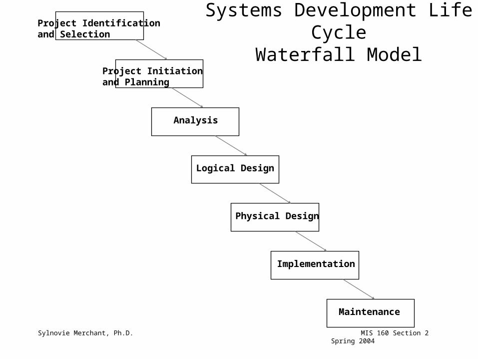
Systems Development Life CycleWaterfall Model
Project Identification and Selection
Project Initiationand Planning
Analysis
Logical Design
Physical Design
Implementation
Maintenance

Advantages of Structured Development
• Been used successfully for over 20 years
• Provides a clear framework that defines and divides important activities
• Can be applied to both small and large projects
• Division of labor is easier to facilitate
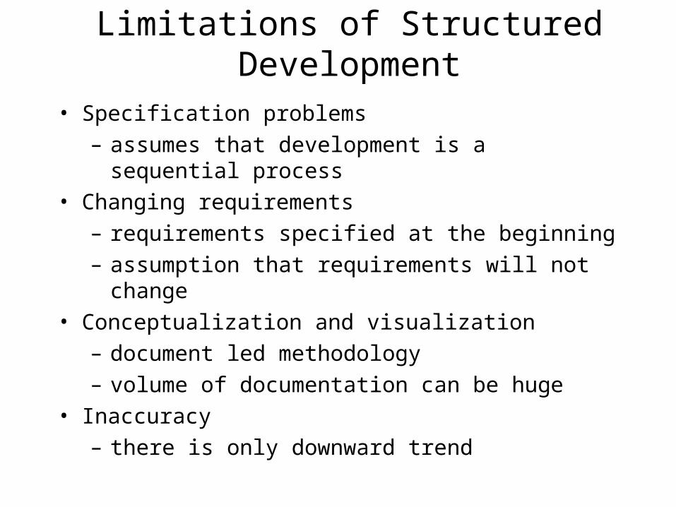
Limitations of Structured Development
• Specification problems
– assumes that development is a sequential process
• Changing requirements
– requirements specified at the beginning
– assumption that requirements will not change
• Conceptualization and visualization
– document led methodology
– volume of documentation can be huge
• Inaccuracy
– there is only downward trend

Approaches to Structured Development
• Gane and Sarson – uses data flow diagrams– data dictionaries, process descriptions, file
layouts
• Yourdon and DeMarco– similar to Gane and Sarson– difference in the symbols that are used

Sylnovie Merchant, Ph.D. MIS 160 Section 2 Spring 2004
Data Flow Diagrams
• Process-oriented approach– examines inputs, outputs, and processes of a system– purpose is to show the flow of information through a system
• 4 Sets of DFDs:– Physical DFDs of current system: show how the current system works– Logical DFDs of current system: show what the system currently does– Logical DFDs of proposed system: show what the new system must do– Physical DFDs of proposed system: show how the new system works

Sylnovie Merchant, Ph.D. MIS 160 Section 2 Spring 2004
Structured Approach Sequence
• Hierarchical Chart
• Physical DFD current system (WHAT/HOW)
• Logical DFD current system (WHAT only)
• Logical DFD proposed system (revised WHAT)
• Physical DFD proposed system (revised WHAT/HOW)

Sylnovie Merchant, Ph.D. MIS 160 Section 2 Spring 2004
Hierarchical Chart
• Terms:– parent,child,sibling– functional primitive– control module
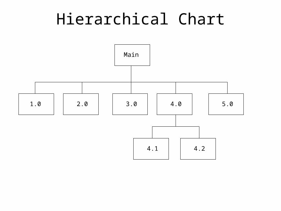
Hierarchical Chart
Main
1.0 2.0 3.0 4.0 5.0
4.24.1

Sylnovie Merchant, Ph.D. MIS 160 Section 2 Spring 2004
Data Flow Diagram (DFD)
• Purpose: communication with user
• Components:– external entities (sources, sinks)– processes (subprograms)– data stores (files)– data flows (forms)

Gane & Sarson
processprocess
data storedata store
source/sinksource/sink
data flowdata flow
Yourdon
Data Flow Diagram (DFD) Symbols
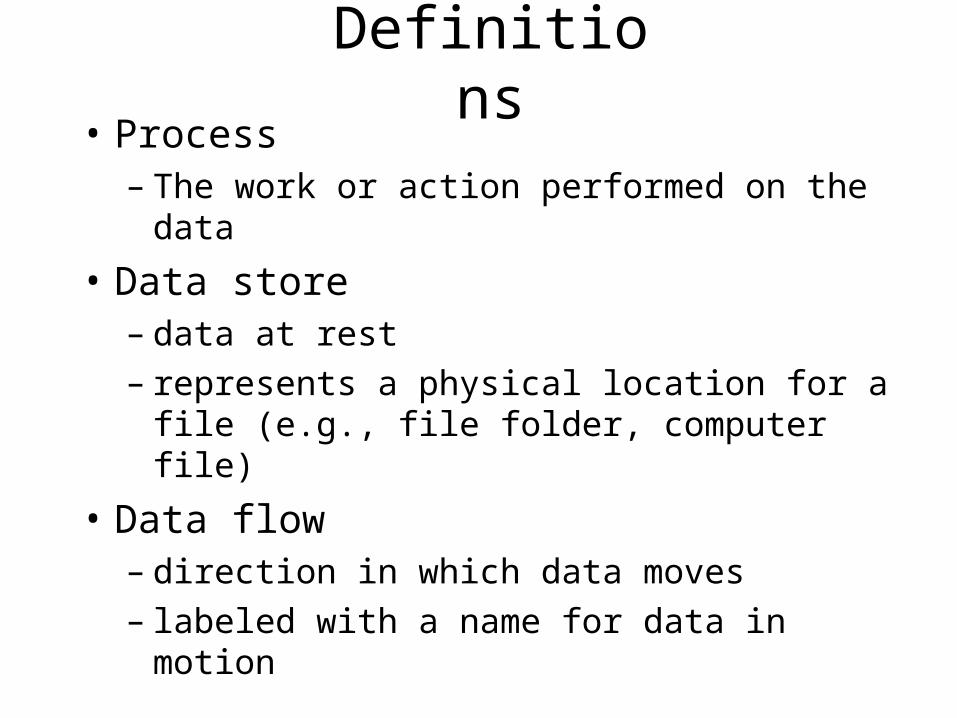
Definitions• Process
– The work or action performed on the data
• Data store– data at rest– represents a physical location for a file (e.g., file
folder, computer file)
• Data flow– direction in which data moves– labeled with a name for data in motion

Definitions• Source/sink
– origin (source) of the data– destination (sink) of the data– sometimes referred to as external entities
(outside of the system)
• Do not consider the following– interactions between sources and sinks– what source/ sink does with the information– design/redesign of source/sink– direct access of source/sink to stored data

A Simple Sample
1.0
HospitalPharmacy
System
2.0
ReviewPrescription
Doctor
Prescription
Unfilled Order Info.
Unfilled Response
Prescription
D1 Patient File
Tech Review
PatientInfo
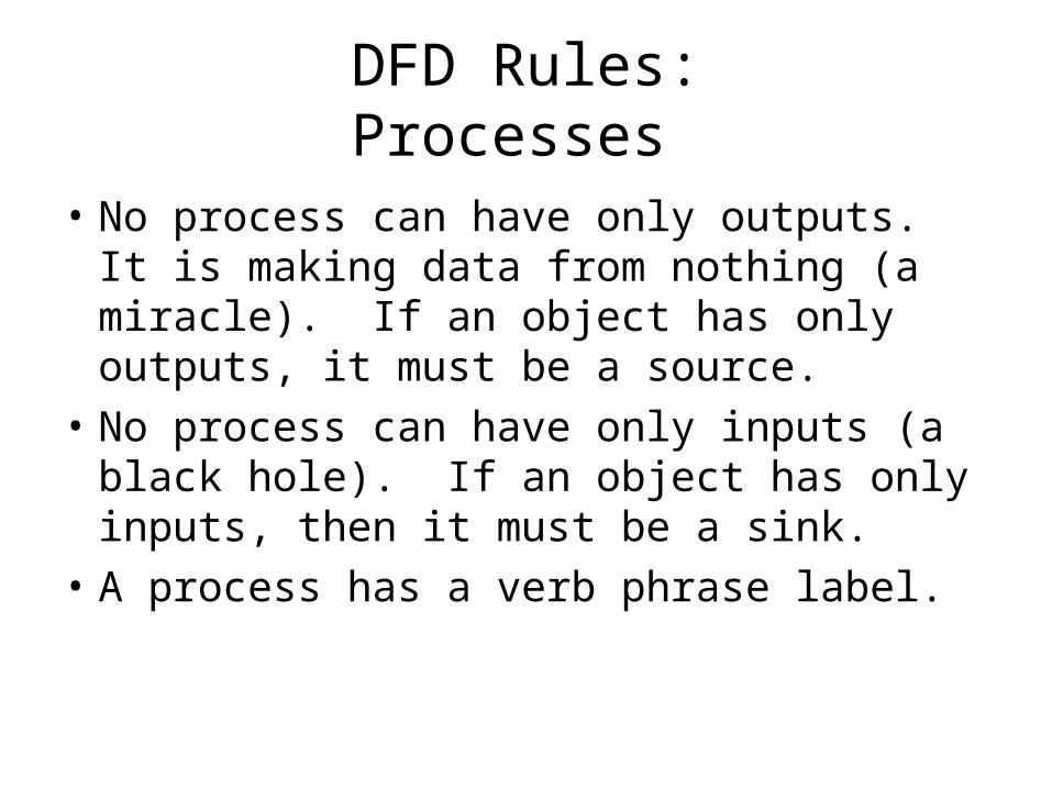
DFD Rules:Processes
• No process can have only outputs. It is making data from nothing (a miracle). If an object has only outputs, it must be a source.
• No process can have only inputs (a black hole). If an object has only inputs, then it must be a sink.
• A process has a verb phrase label.

DFD Rules: Processes
Member
1.0
Member informationRecruit
Members
Black hole
Member
1.0
MembershipRecruit
Members
Miracle

DFD Rules: Data Stores
• Data cannot move directly from one data store to another data store. Data must be moved by a process.
• Data cannot move directly from an outside source to a data store. Data must be moved by a process which receives data from the source and places the data into the data store.
• Data cannot move directly to an outside sink from a data store. Data must be moved by a process.
• A data store has a noun phrase label.

DFD Rules: Data Stores
Member
D2 Memberships
D1 Members
Renewal noticeD2 Memberships
Member Renewal notice D2 Memberships
MembershipInformation

DFD Rules: Sources/Sinks
• Data cannot move directly from a source to a sink. It must be moved by a process if the data are of any concern to our system. Otherwise, the data flow is not shown on the DFD.
• A source/sink has a noun phrase label.
Member Member information Clerk

Context Level
0
DepartmentStaff
Student
FinancialOffice
Course Registration
System
Course Information
Course Information
Course OfferingsFees data
Enrollment InformationSchedule
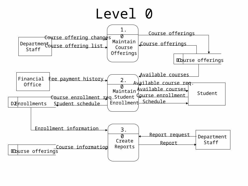
Level 0
MaintainCourse
Offerings
2.0
MaintainStudent
Enrollment
3.0
CreateReports
DepartmentStaff
Financial Office
Student
Course offering changes
Course offering list
Fee payment history
D1 Course offerings
Available course req.Available courses.
ScheduleCourse enrollment
D2 EnrollmentsCourse enrollment req.Student schedule
Enrollment informationReport request Department
Staff Report
Available courses
Course offerings
Course offerings
D1 Course offeringsCourse information
1.0
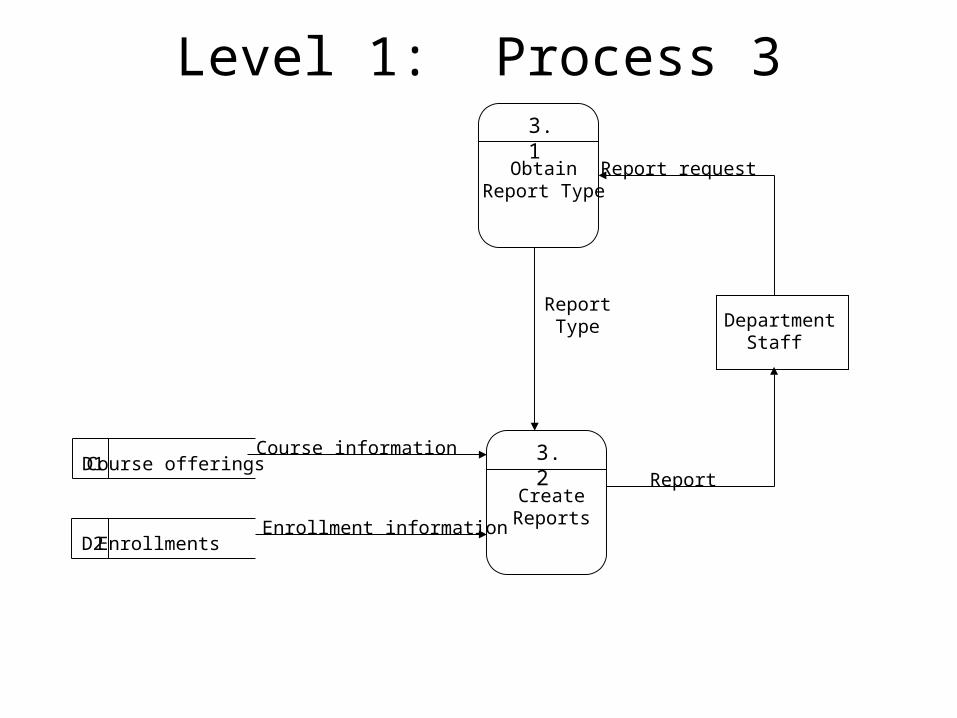
Level 1: Process 33.1
ObtainReport Type
D2 Enrollments
DepartmentStaff
3.2
CreateReports
D1 Course offeringsCourse information
Enrollment information
Report request
Report
ReportType
Models and Modeling
• Models are frequently used for documenting functional requirements
– Created during analysis activity phase called ‘define system requirements’
– Focus on events and things
• Models are used in both the traditional and object-oriented approach

Models and Modeling
• Analyst describes information system requirements using a collection of models
• Complex systems require more than one type of model
• Models represent some aspect of the current system/ system being built