Embed Size (px)
Citation preview
SYLLABUS
Alternators - basic principle, constructional features of salient pole type and cylindrical type alternators, advantages of stationary armature, turbo-alternator.
Armature winding – types of armature winding- single layer, double layer, full pitched and short pitched winding, slot angle, pitch factor and distribution factor – numerical problems.
Effect of pitch factor on harmonics – advantages of short chorded winding,
EMF Equation – numerical problems. Harmonics in generated EMF – suppression of harmonics.
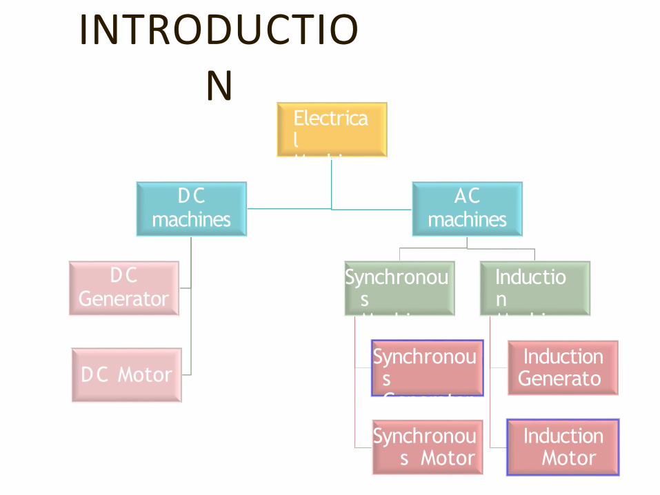
INTRODUCTION
Electrical MachinesDC
machines
DC Motor
DCGenerator
ACmachines
Synchronous Machines
Synchronous Generator
Synchronous Motor
Induction Machines
Induction Generator
Induction Motor
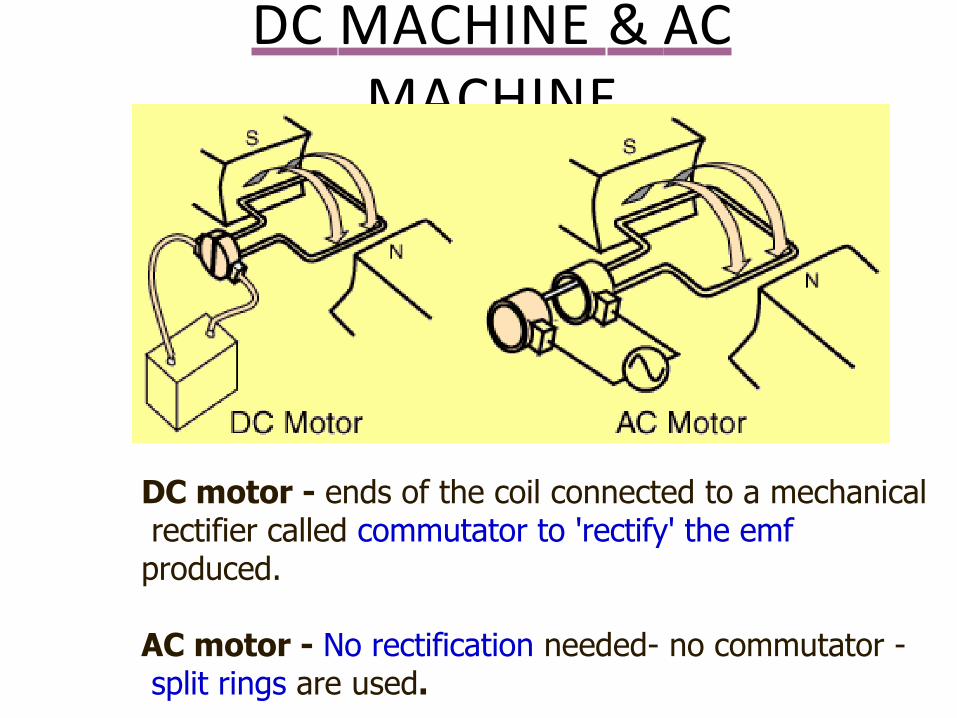
DC MACHINE & AC MACHINE
DC motor - ends of the coil connected to a mechanical rectifier called commutator to 'rectify' the emf produced.
AC motor - No rectification needed- no commutator - split rings are used.
AC GENERATOR
• Alternating Current Generator – Alternator
• Alternator – Synchronous Generator (mechanical energy to electrical energy )
• Synchronous Machine converting electrical energy to mechanical energy – Synchronous Motor
PRINCIPLE OF OPERATION
• Faraday’s Laws–Whenever flux linking a conductor changes an emf
is induced in it
–The induced emf is directly proportional to rate of change of flux linkage
• Lenz’s Law–The direction of emf is such that the current
set by it tends to oppose the change producing it.
T – no. of Turns Φ - Flux
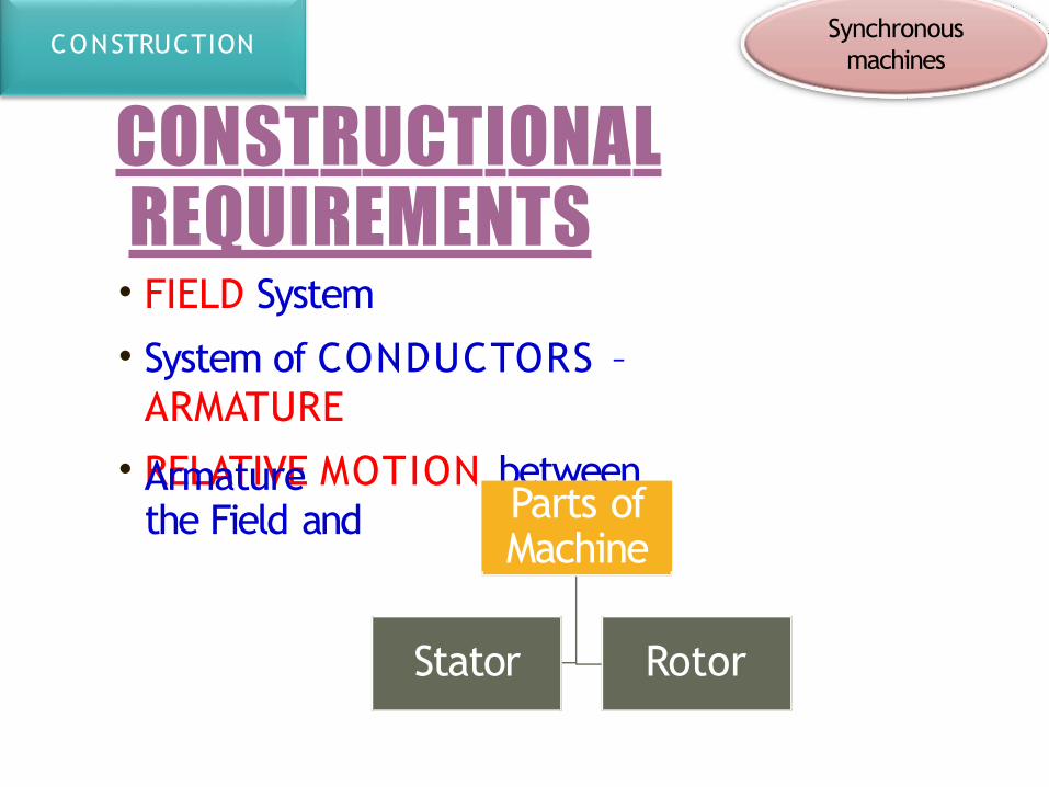
CONSTRUCTIONAL REQUIREMENTS• FIELD System
• System of CONDUCTORS – ARMATURE
• RELATIVE MOTION between the Field andArmature
Parts ofMachine
Stator Rotor
Synchronousmachines
CONSTRUCTION
CONSTRUCTIONAL
REQUIREMENTS• Relative Motion can be achieved by keeping Field as stator and Armature as rotor or vice-versa–Stationary Field system
–Rotating Field system
• Rotor is connected to the external circuit usingslip-rings and brushes.
CONSTRUCTION
ROTATING FIELD SYSTEM-
ADVANTAGES
CONSTRUCTION
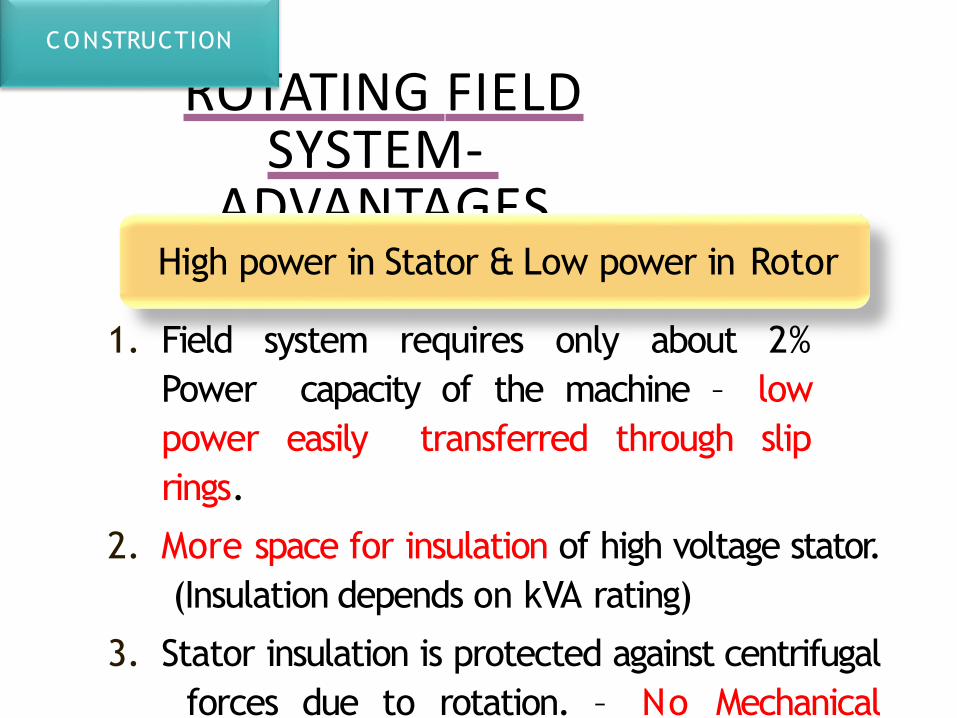
High power in Stator & Low power in Rotor
1. Field system requires only about 2% Power capacity of the machine – low power easily transferred through slip rings.
2. More space for insulation of high voltage stator. (Insulation depends on kVA rating)
3. Stator insulation is protected against centrifugal forces due to rotation. – No Mechanical Stress
ROTATING FIELD SYSTEM-
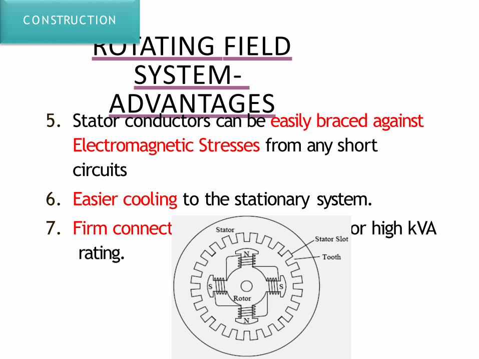
ADVANTAGES5. Stator conductors can be easily braced against
Electromagnetic Stresses from any short circuits
6. Easier cooling to the stationary system.
7. Firm connection to external circuit for high kVA rating.
CONSTRUCTION
STATOR- PARTS
1. Frame
2. Stator Core
3. Stator Windings
4. Cooling arrangements
CONSTRUCTION
STATOR- PARTSCONSTRUCTION
STATOR- PARTS
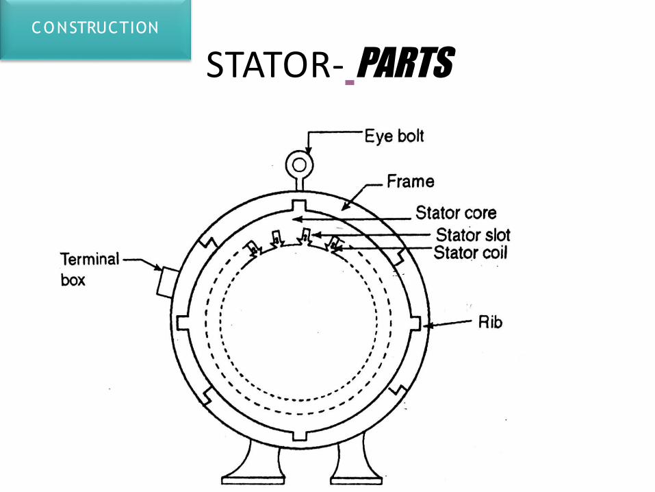
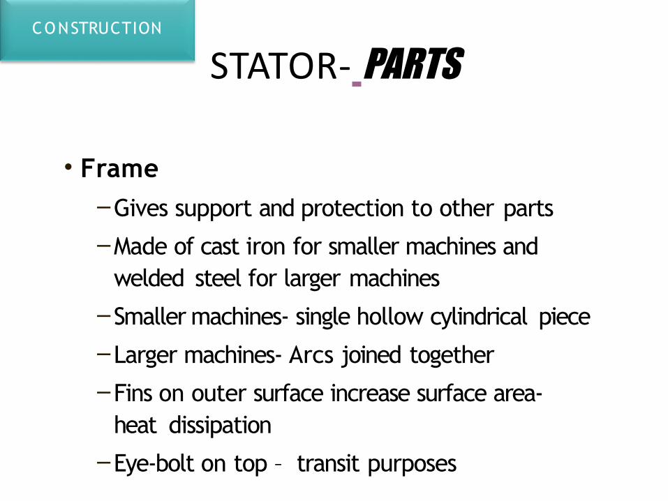
• Frame–Gives support and protection to other parts
–Made of cast iron for smaller machines and welded steel for larger machines
–Smaller machines- single hollow cylindrical piece
–Larger machines- Arcs joined together
–Fins on outer surface increase surface area- heat dissipation
–Eye-bolt on top – transit purposes
CONSTRUCTION
STATOR- PARTS
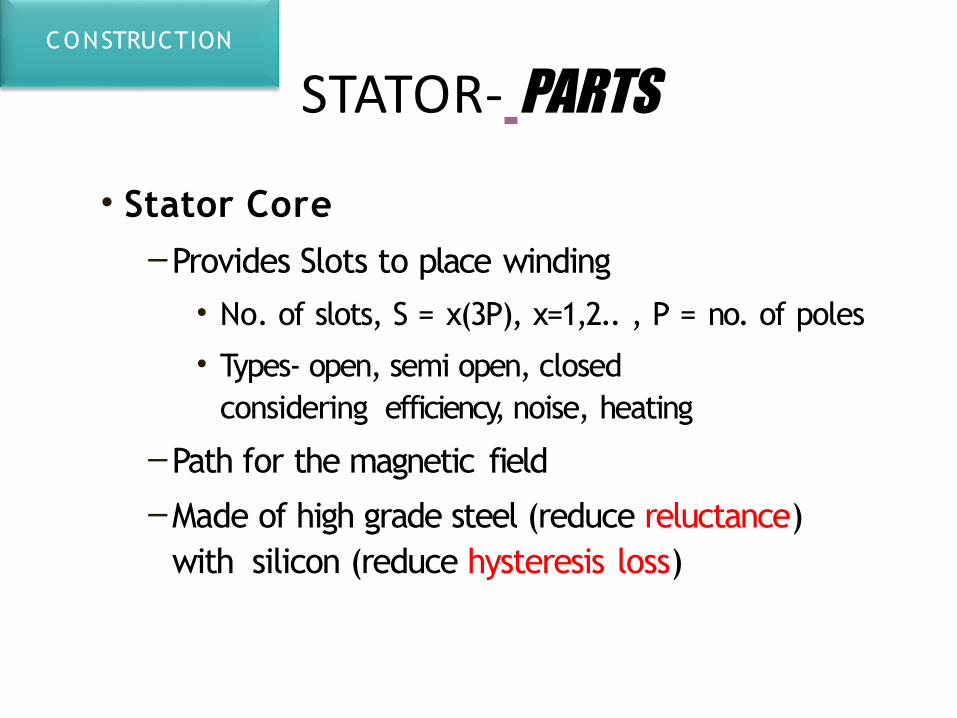
• Stator Core–Provides Slots to place winding
• No. of slots, S = x(3P), x=1,2.. , P = no. of poles
• Types- open, semi open, closed considering efficiency, noise, heating
–Path for the magnetic field
–Made of high grade steel (reduce reluctance) with silicon (reduce hysteresis loss)
CONSTRUCTION
STATOR- PARTS
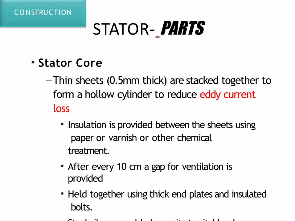
• Stator Core–Thin sheets (0.5mm thick) are stacked together to
form a hollow cylinder to reduce eddy current loss
• Insulation is provided between the sheets using paper or varnish or other chemical treatment.
• After every 10 cm a gap for ventilation is provided
• Held together using thick end plates and insulated bolts.
• Steel ribs are welded over it at suitable places
• Assembled core is inserted into the frame
CONSTRUCTION
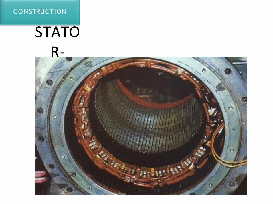
STATOR- PARTS
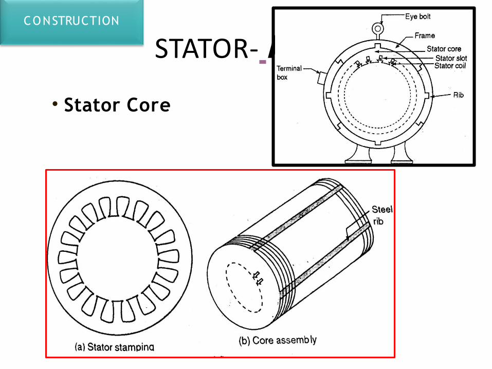
• Stator Core
CONSTRUCTION
STATOR- PARTS
• Stator Winding–AC winding (3-Phase)
–Former wound windings are place in the slots after proper insulation
–The slots are then closed with wooden wedges
–Coils belonging to each phase are normally connected in series
–One starting end and one finishing end are available outside for each phase
CONSTRUCTION
STATOR-
CONSTRUCTION
ROTOR• POLES-
–Contains even no. of poles
– Electromagnetic poles for control of generated emf.
– No. of poles depends on the speed of operation (which depends on the type of turbine or the source of mechanical power)
• Excitation is given by an external source or a built in generator (exciter)
• Excitation is given through slip-rings fixed on the shaft.
CONSTRUCTION
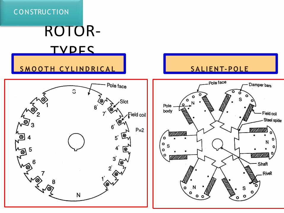
ROTOR- TYPES
S M O O T H C Y L I N D R I C A L SAL IENT-POLE
CONSTRUCTION
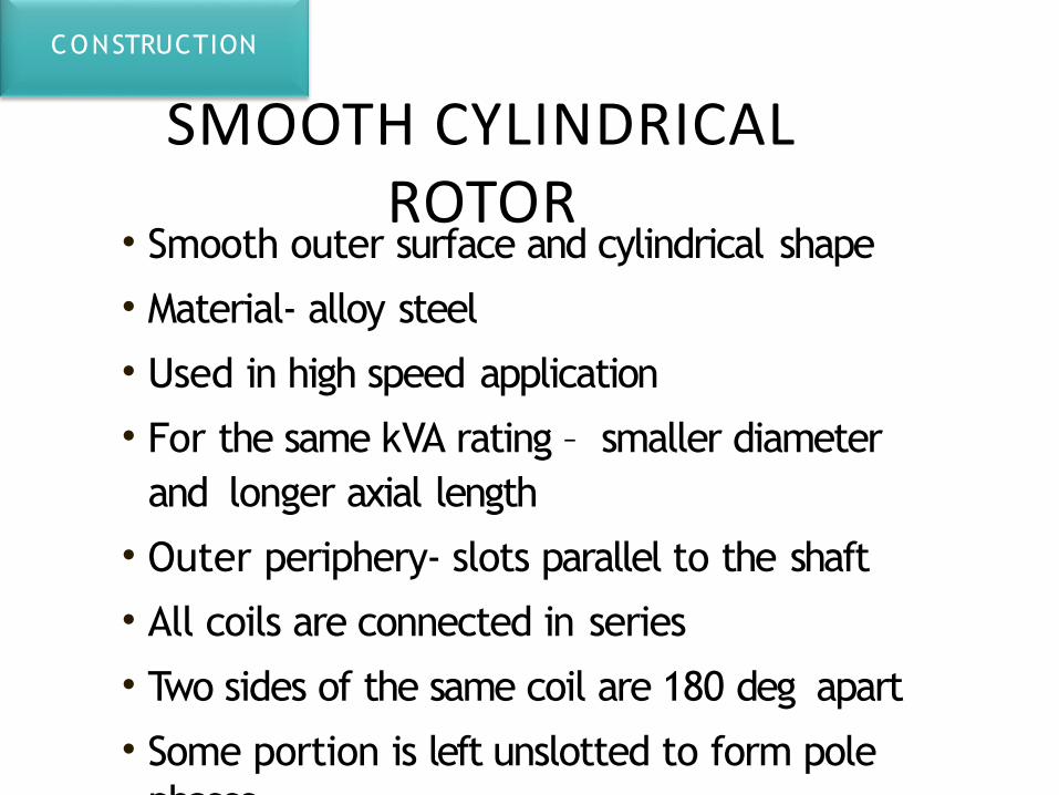
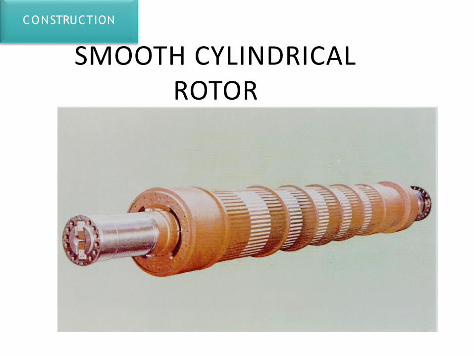
SMOOTH CYLINDRICAL ROTOR
• Smooth outer surface and cylindrical shape
• Material- alloy steel
• Used in high speed application
• For the same kVA rating – smaller diameter and longer axial length
• Outer periphery- slots parallel to the shaft
• All coils are connected in series
• Two sides of the same coil are 180 deg apart
• Some portion is left unslotted to form pole phases.
CONSTRUCTION
SMOOTH CYLINDRICAL ROTOR
• Forced ventilation for proper cooling
• Flux density is maximum along the pole axis and gradually falls away
• Heavy wedges of non-magnetic steel keep the coils intact inside the slots
CONSTRUCTION
SMOOTH CYLINDRICAL ROTOR
CONSTRUCTION
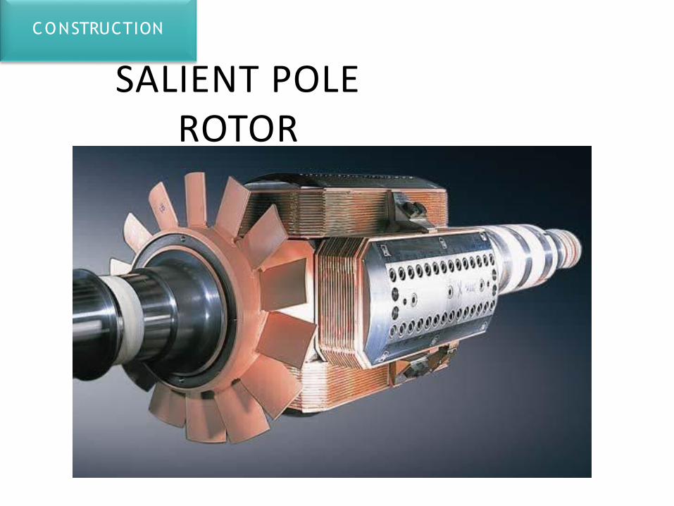
SALIENT POLE ROTOR
CONSTRUCTION
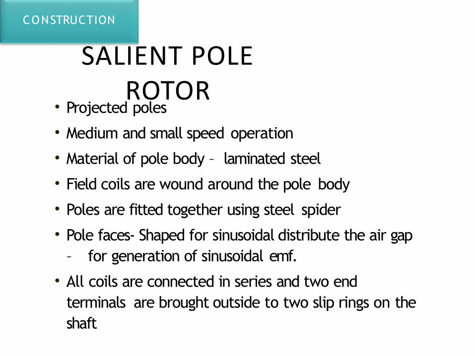
• Projected poles
• Medium and small speed operation
• Material of pole body – laminated steel
• Field coils are wound around the pole body
• Poles are fitted together using steel spider
• Pole faces- Shaped for sinusoidal distribute the air gap – for generation of sinusoidal emf.
• All coils are connected in series and two end terminals are brought outside to two slip rings on the shaft
SALIENT POLE ROTOR
CONSTRUCTION
• Through brushes connections are taken to the terminal box
• When DC supply is given, alternate North and South poles are set up.
• DAMPER WINDINGS-– Damps out oscillations when machine is subjected to
sudden load changes
– Copper bars in closed slots in the pole faces
SALIENT POLE ROTOR
CONSTRUCTION
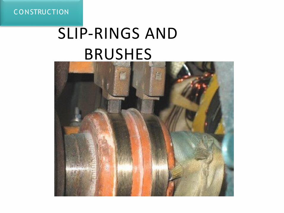
SLIP-RINGS AND BRUSHES
CONSTRUCTION
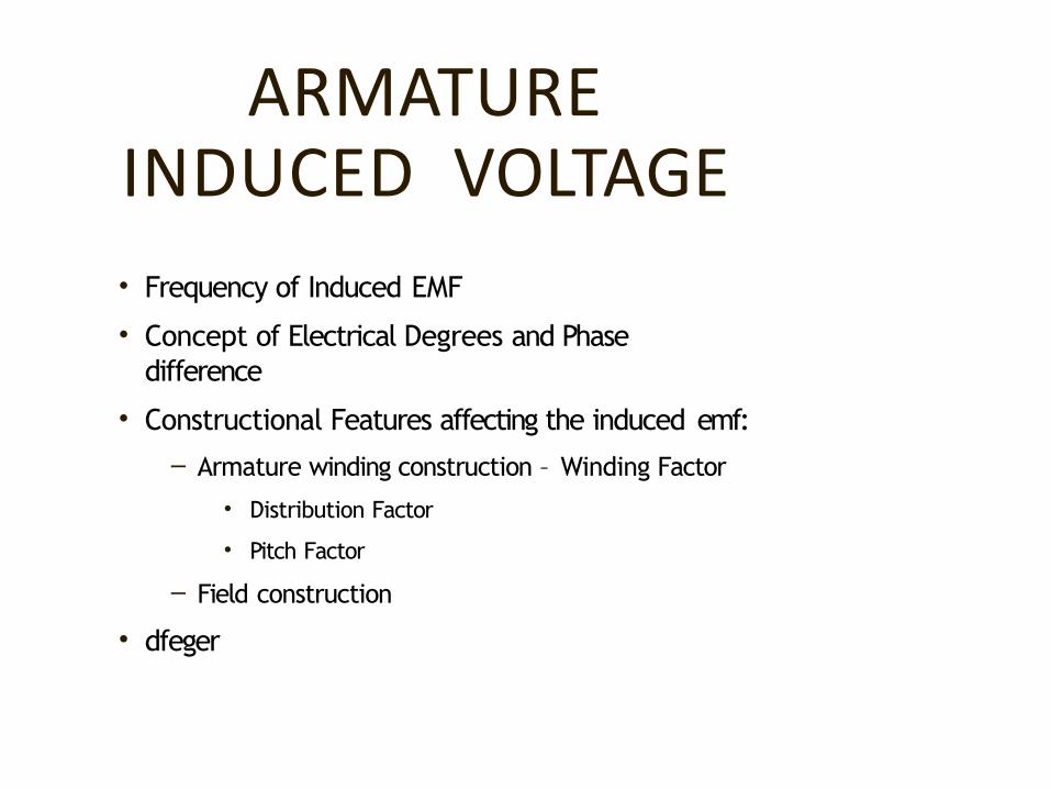
ARMATURE INDUCED VOLTAGE
• Frequency of Induced EMF
• Concept of Electrical Degrees and Phase difference
• Constructional Features affecting the induced emf:
– Armature winding construction – Winding Factor
• Distribution Factor
• Pitch Factor
– Field construction
• dfeger
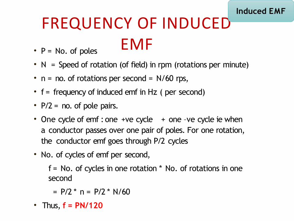
FREQUENCY OF INDUCED EMF• P = No. of poles
• N = Speed of rotation (of field) in rpm (rotations per minute)
• n = no. of rotations per second = N/60 rps,
• f = frequency of induced emf in Hz ( per second)
• P/2 = no. of pole pairs.
• One cycle of emf : one +ve cycle + one –ve cycle ie when a conductor passes over one pair of poles. For one rotation, the conductor emf goes through P/2 cycles
• No. of cycles of emf per second,
f = No. of cycles in one rotation * No. of rotations in one second
= P/2 * n = P/2 * N/60
• Thus, f = PN/120
Induced EMF

NOTE: WHY ‘SYNCHRONOUS
MACHINE’• Synchronous machine – Speed of flux
(Synchronous speed) = Speed of machine
• Synchronous generator – works synchronously with other alternators connected to the Grid
• Synchronous motor – Speed of motor is synchronous with speed of flux i.e directly related to frequency of the supply
Induced EMF
ELECTRICAL & MECHANICAL ANGLE
• Mechanical angle: With Reference to spacial or physical location, one complete rotation = 360 deg. mech.
• Electrical angle: With Reference to polarity of Magnetic field, one cycle of flux distribution waveform completes in 360 deg. ele.
• For both:
• 0 deg – Reference point
• 180 deg – Opposite point
• 360 deg – Similar point
Induced EMF
ELECTRICAL & MECHANICAL ANGLE IN ELECTRICAL
MACHINE• point same as Mechanical reference)
• 180 deg – Opposite point (Points under two
adjacent poles (N and S) are 180 deg apart as flux
direction is ecactly opposite under each)
• 360 deg – Similar point
point same as electrical reference)
• 180 deg – Opposite point (Physically opposite point or direction)
• 360 deg – Similar point (same as reference)
• Mechanical Angle • Electrical Angle• 0 deg – Reference point (starting • 0 deg – Reference point
(starting
Induced EMF
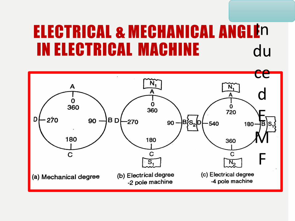
ELECTRICAL & MECHANICAL ANGLE IN ELECTRICAL MACHINE
Induced EMF
3-PHASE WINDING
• D C windings – closed windings, with or without parallel paths
• AC windings -– open ended
– no parallel paths
– 3 identical sets for the 3 phases
– Two end terminals for each phase
– The phases can be connected in star or delta externally
Induced EMF
SOME TERMS & SYMBOLS•
Induced EMF
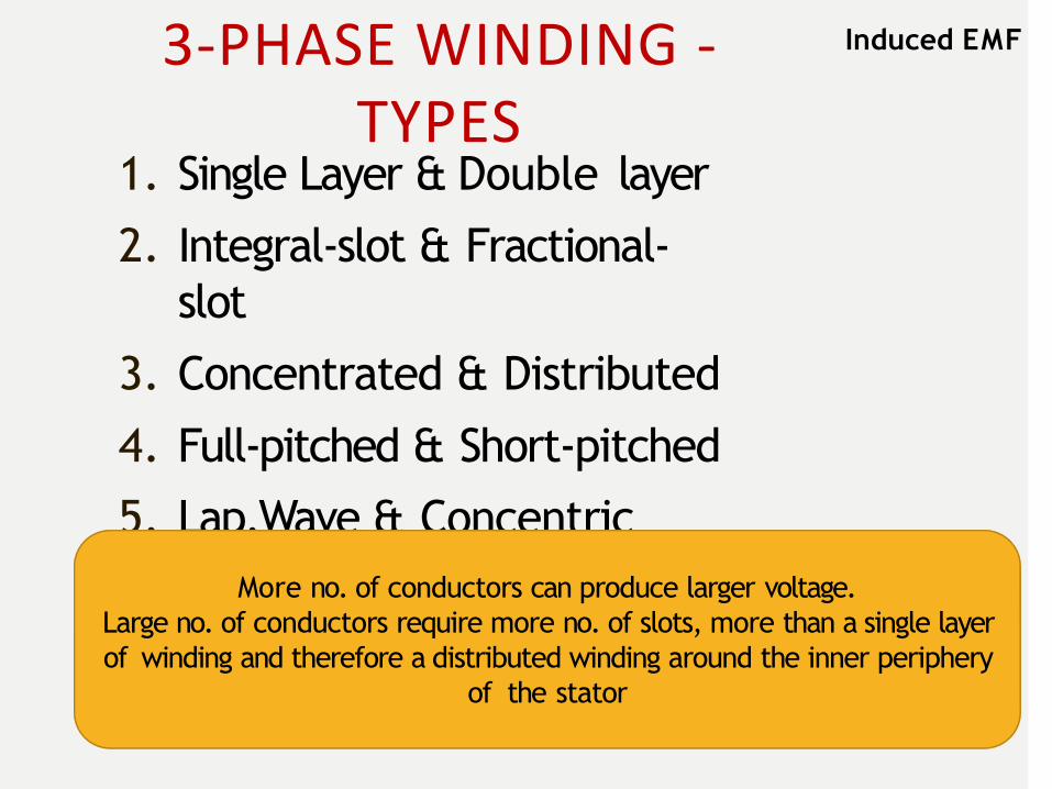
3-PHASE WINDING - TYPES
1. Single Layer & Double layer
2. Integral-slot & Fractional-slot
3. Concentrated & Distributed
4. Full-pitched & Short-pitched
5. Lap,Wave & ConcentricMore no. of conductors can produce larger voltage.
Large no. of conductors require more no. of slots, more than a single layer of winding and therefore a distributed winding around the inner periphery
of the stator
Induced EMF
MODULE II
Performance of Alternator – Causes of voltage drop in Alternator, Synchronous impedance, Phasor diagram of loaded Alternator, Voltage
regulation
Alternator on load- When load on the alternator is varied (i.e, armature current is
varied), the terminal voltage (V) of the alternator also varies, even if the speed & field excitation kept constant
- The variation in terminal voltage is due to the following reasons
1. Voltage drop due to armature resistance (IRa drop)
2. Voltage drop due to armature leakage reactance (IXL drop)
3. Voltage drop due to armature reaction
1. Armature resistance (Ra) – Since the armature (stator) winding
has some resistance, there will be an IRa drop when armature
current flows through it
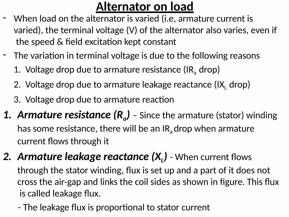
2. Armature leakage reactance (XL) - When current flows
through the stator winding, flux is set up and a part of it does not cross the air-gap and links the coil sides as shown in figure. This flux is called leakage flux.
- The leakage flux is proportional to stator current
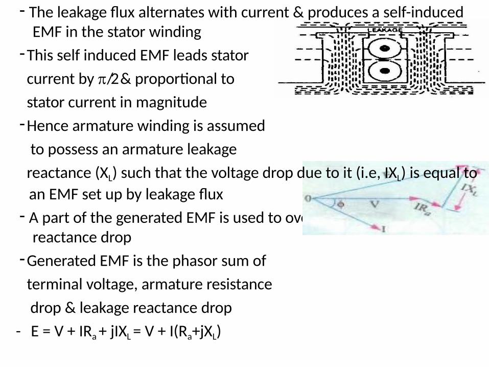
- The leakage flux alternates with current & produces a self-induced EMF in the stator winding
-This self induced EMF leads stator
current by /2 & proportional to
stator current in magnitude
-Hence armature winding is assumed
to possess an armature leakage
reactance (XL) such that the voltage drop due to it (i.e, IXL) is equal to
an EMF set up by leakage flux
- A part of the generated EMF is used to overcome the leakage reactance drop
-Generated EMF is the phasor sum of
terminal voltage, armature resistance
drop & leakage reactance drop
- E = V + IRa + jIXL = V + I(Ra+jXL)
3. Armature reaction- When an alternator is running at no load, there will be no current flowing
through the armature winding.
- The flux produced in the air gap will be only due to the rotor ampere-turns.
- When the alternator is loaded, the three phase stator currents will produce a resultant rotating magnetic field in the air gap.
- Consequently, the air gap flux is changed from the no load condition
- The effect of armature flux on the flux produced by field ampere-turns (main field winding) is called armature reaction
- The armature flux and the flux produced by rotor ampere-turns rotate at the same speed (synchronous speed) in the same direction and, therefore, the two fluxes are fixed in space relative to each other.
- The modification of flux in the air gap due to armature flux depends on the magnitude of stator current and on the power factor of the load.
- It is the load power factor which determines whether the armature flux distorts, opposes or helps the flux produced by rotor ampere-turns
- Under normal operating condition (i.e, power factor = 1), the armature (stator) mmf lags behind the main field mmf by 90◦ electrical.
Consider the following 3 cases,
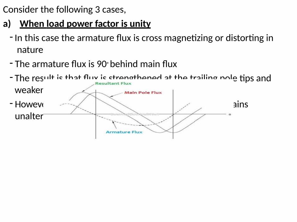
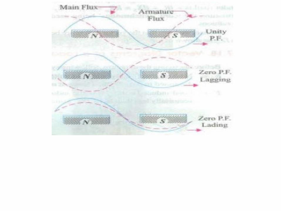
a) When load power factor is unity
- In this case the armature flux is cross magnetizing or distorting in nature
- The armature flux is 90◦ behind main flux
- The result is that flux is strengthened at the trailing pole tips and weakened at the leading pole tips.
- However, the average flux in the air gap practically remains unaltered
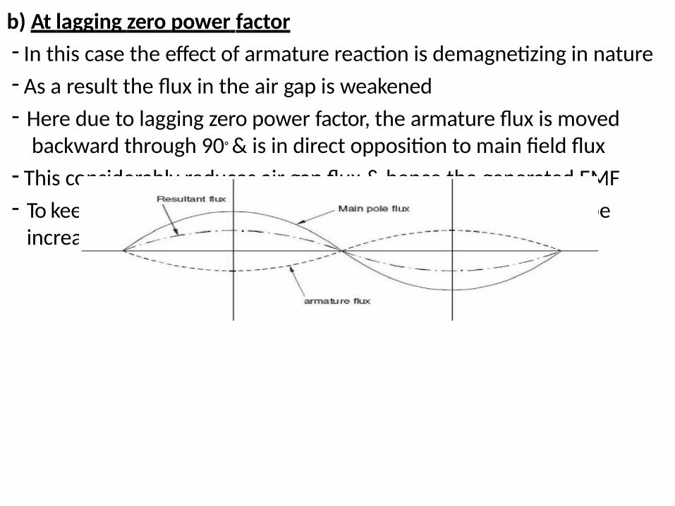
b) At lagging zero power factor
- In this case the effect of armature reaction is demagnetizing in nature
- As a result the flux in the air gap is weakened
- Here due to lagging zero power factor, the armature flux is moved backward through 90◦ & is in direct opposition to main field flux
- This considerably reduces air gap flux & hence the generated EMF
- To keep the value of generated EMF, the field excitation has to be increased
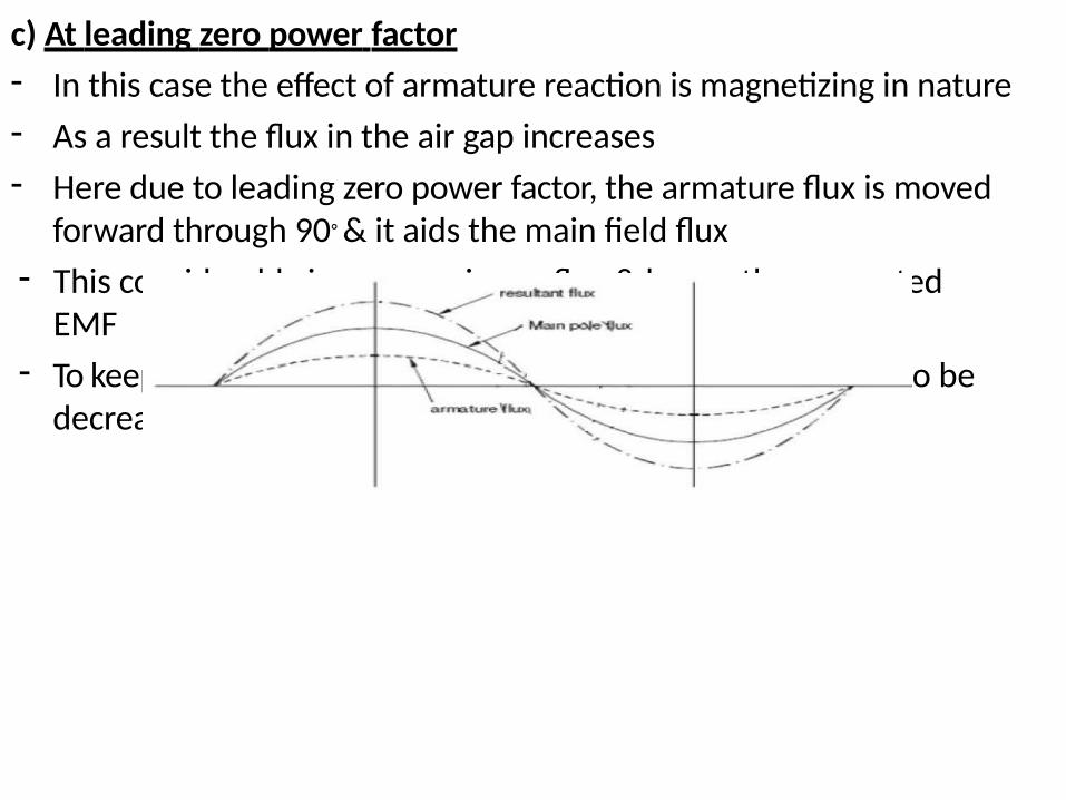
c) At leading zero power factor
- In this case the effect of armature reaction is magnetizing in nature
- As a result the flux in the air gap increases
- Here due to leading zero power factor, the armature flux is moved forward through 90◦ & it aids the main field flux
- This considerably increases air gap flux & hence the generated EMF
- To keep the value of generated EMF, the field excitation has to be decreased
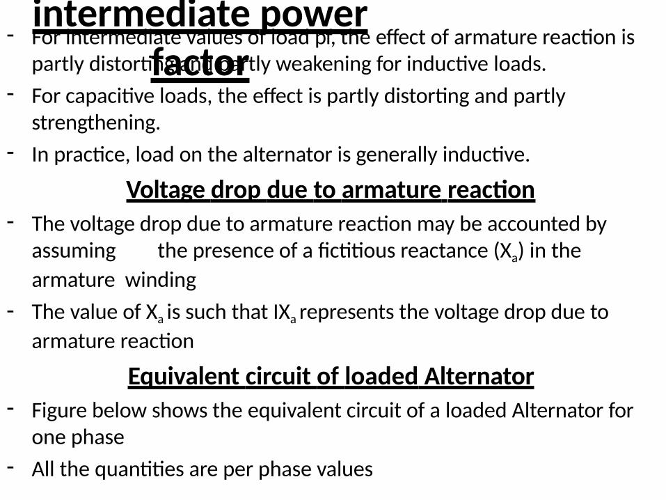
d) At any other intermediate power
factor- For intermediate values of load pf, the effect of armature reaction is
partly distorting and partly weakening for inductive loads.
- For capacitive loads, the effect is partly distorting and partly strengthening.
- In practice, load on the alternator is generally inductive.
Voltage drop due to armature reaction- The voltage drop due to armature reaction may be accounted by
assuming the presence of a fictitious reactance (Xa) in the
armature winding
- The value of Xa is such that IXa represents the voltage drop due to
armature reaction
Equivalent circuit of loaded Alternator- Figure below shows the equivalent circuit of a loaded Alternator for
one phase
- All the quantities are per phase values
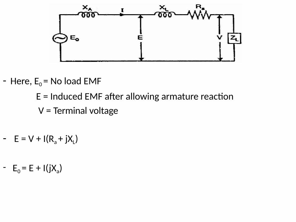
- Here, E0 = No load EMF
E = Induced EMF after allowing armature reaction
V = Terminal voltage
- E = V + I(Ra + jXL)
- E0 = E + I(jXa)
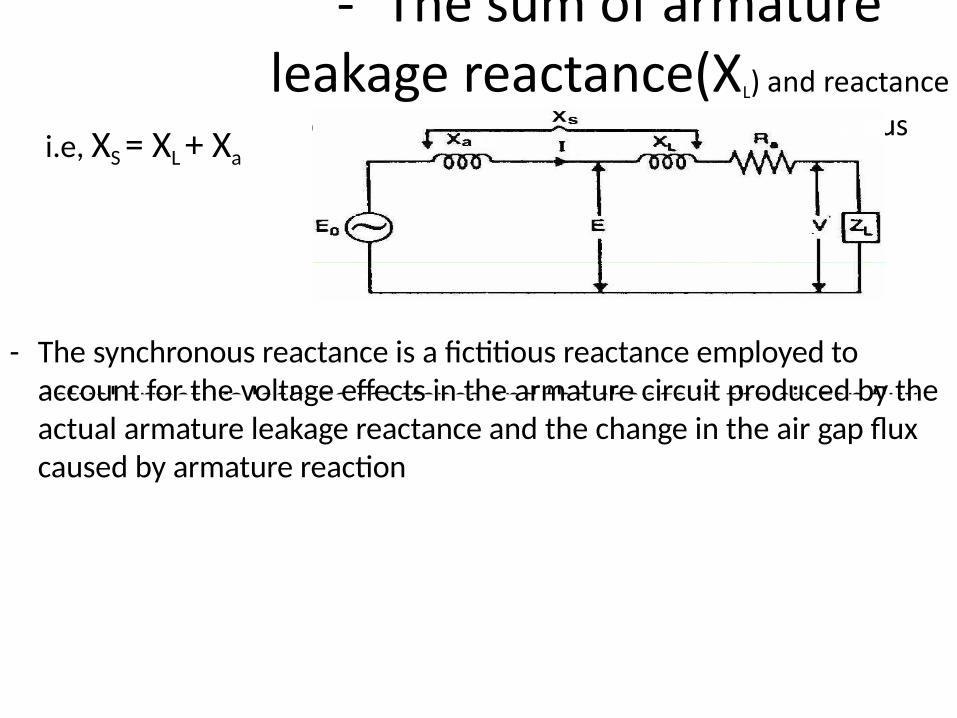
Synchronous reactance (XS)
- The sum of armature leakage reactance(XL) and reactance
of armature reaction(Xa) is called synchronous
reactance, XS
i.e, XS = XL + Xa
actual armature leakage reactance and the change in the air gap flux
- The synchronous reactance is a fictitious reactance employed to account for the voltage effects in the armature circuit produced by the actual armature leakage reactance and the change in the air gap flux caused by armature reaction
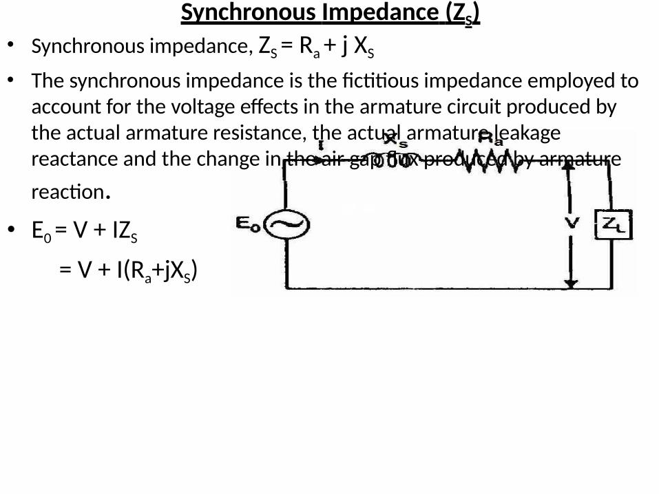
Synchronous Impedance (ZS)• Synchronous impedance, ZS = Ra + j XS
• The synchronous impedance is the fictitious impedance employed to account for the voltage effects in the armature circuit produced by the actual armature resistance, the actual armature leakage reactance and the change in the air gap flux produced by armature
reaction.
• E0 = V + IZS
= V + I(Ra+jXS)
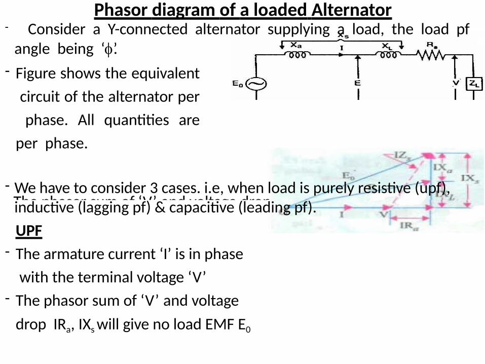
Phasor diagram of a loaded Alternator
- The phasor sum of ‘V’ and voltage drop
- Consider a Y-connected alternator supplying a load, the load pf angle being ‘’.
- Figure shows the equivalent
circuit of the alternator per
phase. All quantities are
per phase.
- We have to consider 3 cases. i.e, when load is purely resistive (upf), inductive (lagging pf) & capacitive (leading pf).
UPF
- The armature current ‘I’ is in phase
with the terminal voltage ‘V’
- The phasor sum of ‘V’ and voltage
drop IRa, IXs will give no load EMF E0
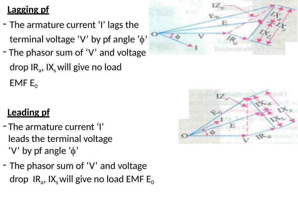
Lagging pf
- The armature current ‘I’ lags the
terminal voltage ‘V’ by pf angle ‘’- The phasor sum of ‘V’ and voltage
drop IRa, IXs will give no load
EMF E0
Leading pf
- The armature current ‘I’ leads the terminal voltage ‘V’ by pf angle ‘’
- The phasor sum of ‘V’ and voltage
drop IRa, IXs will give no load EMF E0
Experimental determination of Synchronous Reactance (XS)2
- Synchronous impedance, Z R 2 X
- Synchronous reactance,
SaS
a2 R 2XS ZS
- If we know synchronous impedance and effective armature resistance, Synchronous impedance can be determined.
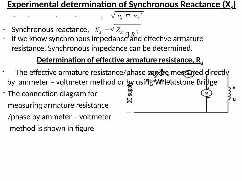
Determination of effective armature resistance, Ra
- The effective armature resistance/phase can be measured directly by ammeter – voltmeter method or by using Wheatstone Bridge
- The connection diagram for
measuring armature resistance
/phase by ammeter – voltmeter
method is shown in figure
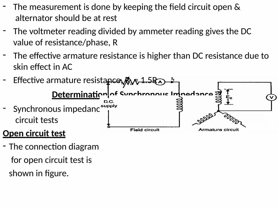
- The measurement is done by keeping the field circuit open & alternator should be at rest
- The voltmeter reading divided by ammeter reading gives the DC value of resistance/phase, R
- The effective armature resistance is higher than DC resistance due to skin effect in AC
- Effective armature resistance, Ra = 1.5R
Determination of Synchronous Impedance, ZS
- Synchronous impedance is determined from open circuit & short circuit tests
Open circuit test
- The connection diagram
for open circuit test is
shown in figure.
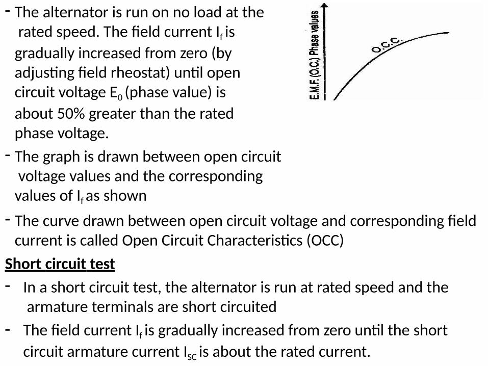
- The alternator is run on no load at the rated speed. The field current If is
gradually increased from zero (by adjusting field rheostat) until open circuit voltage E0 (phase value) is
about 50% greater than the rated phase voltage.
- The graph is drawn between open circuit voltage values and the corresponding values of If as shown
- The curve drawn between open circuit voltage and corresponding field current is called Open Circuit Characteristics (OCC)
Short circuit test
- In a short circuit test, the alternator is run at rated speed and the armature terminals are short circuited
- The field current If is gradually increased from zero until the short
circuit armature current ISC is about the rated current.
- Synchronous impedance can be determined by knowing the value of
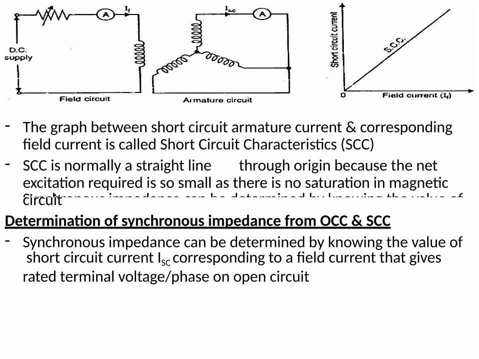
- The graph between short circuit armature current & corresponding field current is called Short Circuit Characteristics (SCC)
- SCC is normally a straight line through origin because the net excitation required is so small as there is no saturation in magnetic circuit
Determination of synchronous impedance from OCC & SCC- Synchronous impedance can be determined by knowing the value of
short circuit current ISC corresponding to a field current that gives rated terminal voltage/phase on open circuit
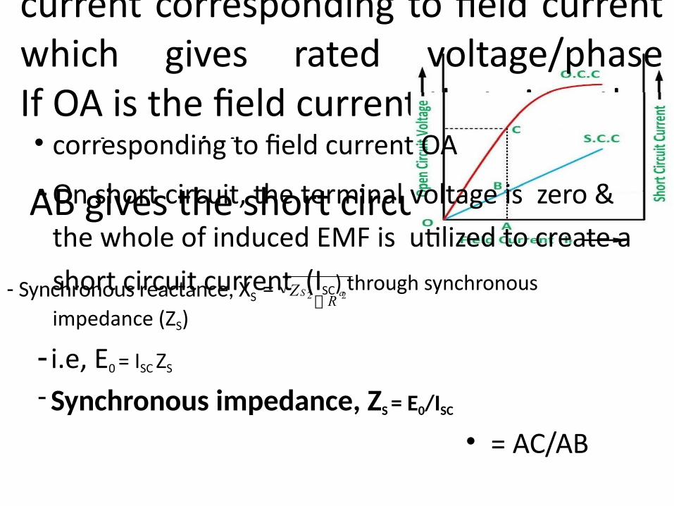
-Synchronous Impedance = Open circuit voltage divided by Short circuit current corresponding to field current which gives rated voltage/phaseIf OA is the field current that gives the rated EMF/phase represented by AC & AB gives the short circuit current ISC
• corresponding to field current OA
- On short circuit, the terminal voltage is zero &
the whole of induced EMF is utilized to create a
short circuit current (ISC) through synchronous
impedance (ZS)
- i.e, E0 = ISC ZS
- Synchronous impedance, ZS = E0/ISC
• = AC/AB
- Synchronous reactance, XS = aSZ 2 R 2
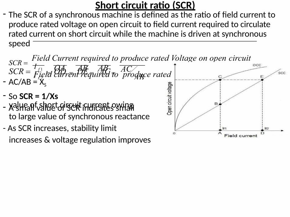
Short circuit ratio (SCR)- The SCR of a synchronous machine is defined as the ratio of field current to
produce rated voltage on open circuit to field current required to circulate rated current on short circuit while the machine is driven at synchronous speed
SCR Field Current required to produce rated Voltage on open circuit
Field current required to produce rated Current on short circuit- From graph,
ACAB
OD DE ACI f 2 OA AB AB 1
SCR I f 1
- AC/AB = XS
- So SCR = 1/Xs- A small value of SCR indicates smallvalue of short circuit current owing
to large value of synchronous reactance
- As SCR increases, stability limit
increases & voltage regulation improves
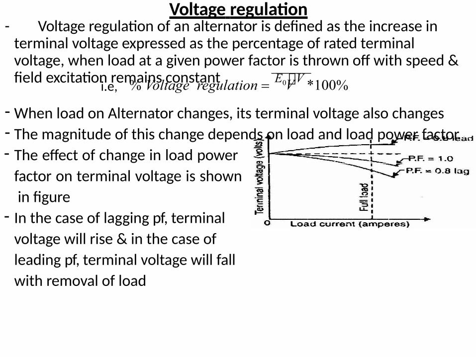
Voltage regulation- Voltage regulation of an alternator is defined as the increase in
terminal voltage expressed as the percentage of rated terminal voltage, when load at a given power factor is thrown off with speed & field excitation remains constant V
Where, E0 = No load terminal voltage, V = Full load terminal voltagei.e, % Voltage regulation E0 V *100%
- When load on Alternator changes, its terminal voltage also changes- The magnitude of this change depends on load and load power factor- The effect of change in load power
factor on terminal voltage is shown
in figure- In the case of lagging pf, terminal
voltage will rise & in the case of
leading pf, terminal voltage will fall
with removal of load
Determination of Voltage regulationa. Direct method
- This method is used to find the regulation of small machines
- Here the Alternator is driven at synchronous speed & field excitation is adjusted to get rated terminal voltage (V)
- Now load is varied to get desired load at desired pf by keeping speed & terminal voltage (V) constant
- Then the entire load is thrown off by keeping the speed & field excitation constant to get no load terminal voltage (E0)
-Now,
V% Voltage Re gulation E0 V *100%- The kVA rating of commercial Alternators are very high & the cost of
finding the regulation by direct loading is high
- So voltage regulation of large Alternators are determined by Indirect method
b.Indirect methodThe indirect methods commonly used to find the regulation of an
Alternator are1. EMF method 2. MMF method
3. ZPF method 4. ASA method
- All these methods require the following data
i) Armature (stator) resistance
ii) Open Circuit Characteristics (OCC)
iii) Short Circuit Characteristics (SCC)
1. EMF method or Synchronous impedance method
• In this method of finding the voltage regulation of an alternator, we find the synchronous impedance ZS (and hence synchronous
reactance XS) of the alternator from the OCC and SCC
• For this reason, it is called synchronous impedance method
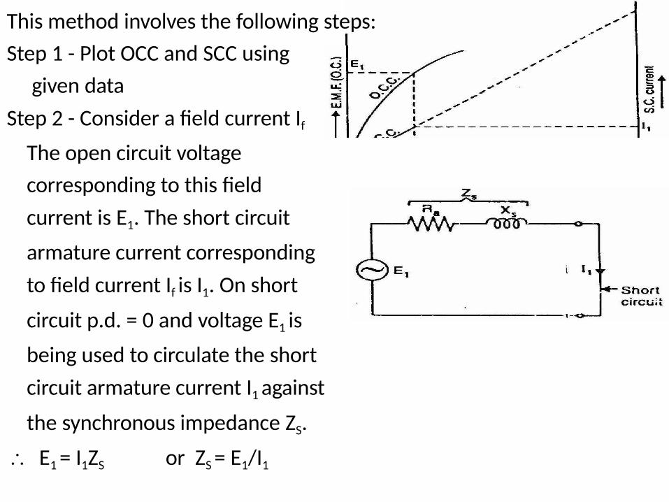
This method involves the following steps:
Step 1 - Plot OCC and SCC using
given data
Step 2 - Consider a field current If
The open circuit voltage
corresponding to this field
current is E1. The short circuit
armature current corresponding
to field current If is I1. On short
circuit p.d. = 0 and voltage E1 is
being used to circulate the short
circuit armature current I1 against
the synchronous impedance ZS.
E1 = I1ZS or ZS = E1/I1
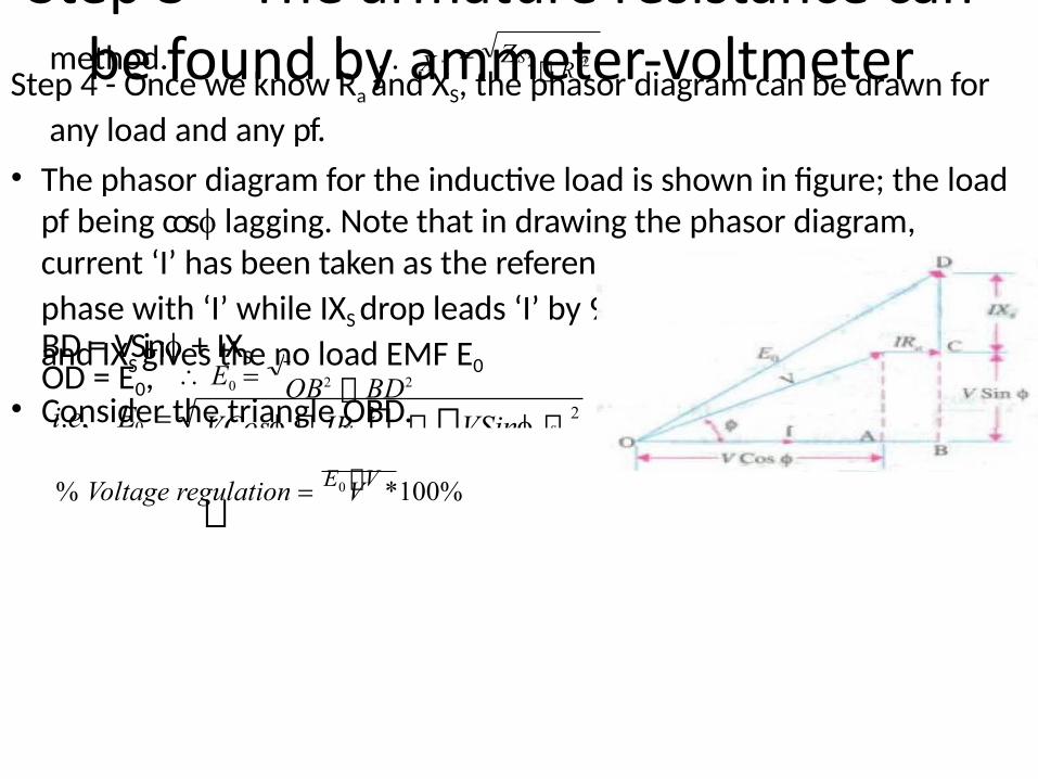
Step 3 – The armature resistance can be found by ammeter-voltmeterS S amethod. X 2 R 2 Z
Step 4 - Once we know Ra and XS, the phasor diagram can be drawn for
any load and any pf.
• The phasor diagram for the inductive load is shown in figure; the load pf being cos lagging. Note that in drawing the phasor diagram, current ‘I’ has been taken as the reference phasor. The IRa drop is in
phase with ‘I’ while IXS drop leads ‘I’ by 90°. The phasor sum of V, IRa
and IXS gives the no load EMF E0
• Consider the triangle OBD.
OB = VCos + IRa
BD = VSin + IXSOD = E0,
OB2 BD2 E0 2 2
0 a si.e, E
VCos IR VSin IX
V% Voltage regulation E0 V *100%
- For leading pf, take as negative & for unity pf, take as zero- This method is called pessimistic method because the regulation
obtained by this method is always higher than actual value- The reason for error is that here synchronous impedance is assumed
to be constant while actually it is not- Synchronous impedance varies with saturation
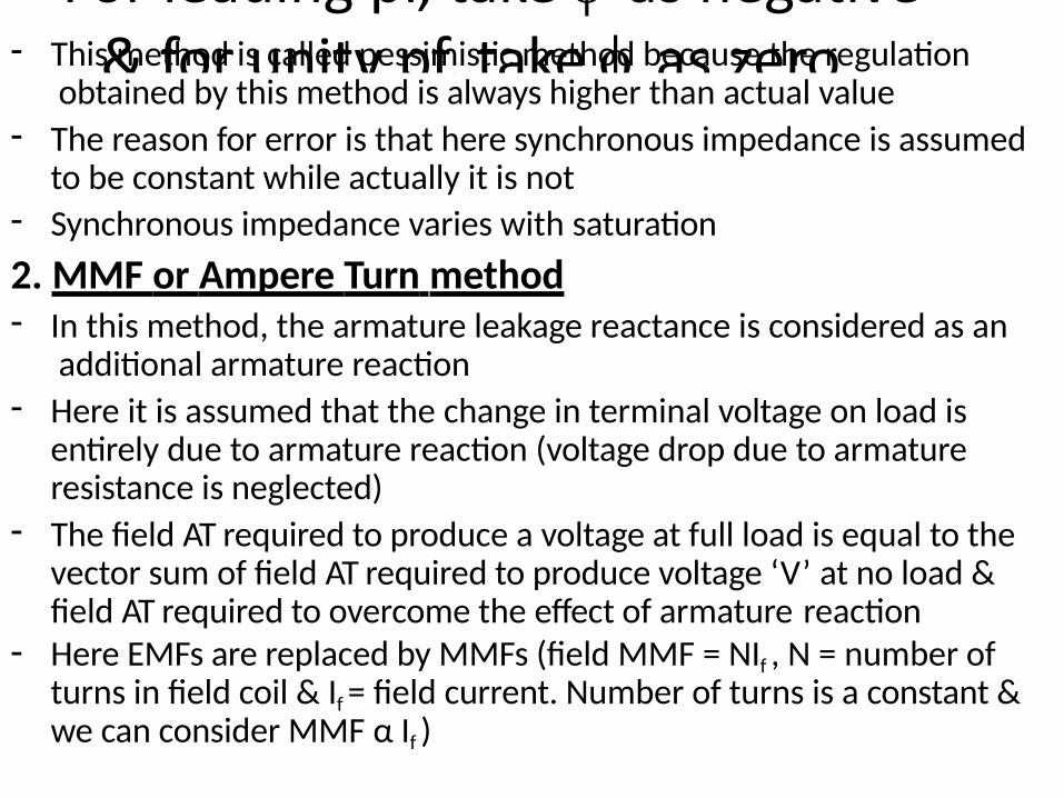
2. MMF or Ampere Turn method- In this method, the armature leakage reactance is considered as an
additional armature reaction- Here it is assumed that the change in terminal voltage on load is
entirely due to armature reaction (voltage drop due to armature resistance is neglected)
- The field AT required to produce a voltage at full load is equal to the vector sum of field AT required to produce voltage ‘V’ at no load & field AT required to overcome the effect of armature reaction
- Here EMFs are replaced by MMFs (field MMF = NIf , N = number of turns in field coil & If = field current. Number of turns is a constant & we can consider MMF α If )
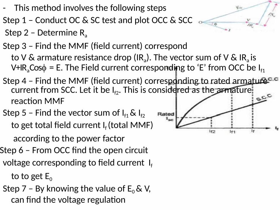
- This method involves the following steps
Step 1 – Conduct OC & SC test and plot OCC & SCC
Step 2 – Determine Ra
Step 3 – Find the MMF (field current) correspondto V & armature resistance drop (IRa). The vector sum of V & IRa is V+IRaCos = E. The Field current corresponding to ‘E’ from OCC be If1
Step 4 – Find the MMF (field current) corresponding to rated armature current from SCC. Let it be If2. This is considered as the armature reaction MMF
Step 5 – Find the vector sum of If1 & If2
to get total field current If (total MMF)
according to the power factor
Step 6 – From OCC find the open circuit
voltage corresponding to field current If
to to get E0
Step 7 – By knowing the value of E0 & V, can find the voltage regulation
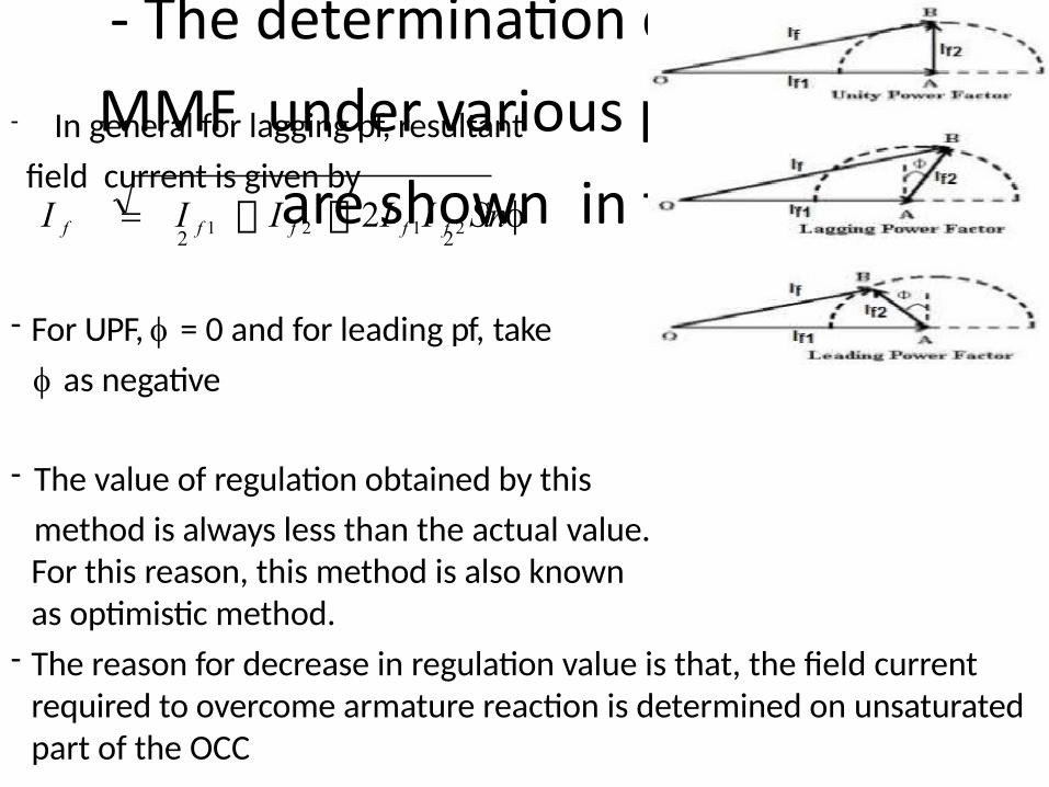
- The determination of resultant
MMF under various pf conditions
are shown in figure
- In general for lagging pf, resultant
field current is given byI f I f 1 I f 2 2I f 1I f 2 Sin
2 2
- For UPF, = 0 and for leading pf, take
as negative
- The value of regulation obtained by this
method is always less than the actual value.For this reason, this method is also known as optimistic method.
- The reason for decrease in regulation value is that, the field current required to overcome armature reaction is determined on unsaturated part of the OCC
3. Zero Power Factor (ZPF) or Potier Method- The voltage regulation obtained by EMF & MMF methods is based on the
total synchronous reactance
- This method is based on the separation of reactance into leakage reactance & reactance due to armature reaction. Therefore this method is more accurate
- The data required for this method are
i) OCC ii) effective armature resistance iii) magnitude of field current
iv) Zero Power Factor (ZPF)required to circulate full load current in stator full load voltage characteristics
Plotting ZPF curve- This is the curve between terminal voltage & field current, when the alternator is delivering full load current to a zero pf (lagging) load
- The test is carried out by running the alternator at synchronous speed & connecting a purely inductive 3 load to its terminals
- There is no need of plotting the full curve, only points A & B are sufficient.
- Point ‘B’ corresponds to the field current which gives rated terminal voltage, when the machine is delivering full load current at zero pf
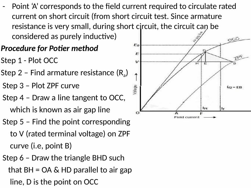
- Point ‘A’ corresponds to the field current required to circulate rated current on short circuit (from short circuit test. Since armature resistance is very small, during short circuit, the circuit can be considered as purely inductive)
Procedure for Potier method
Step 1 - Plot OCC
Step 2 – Find armature resistance (Ra)
Step 3 – Plot ZPF curve
Step 4 – Draw a line tangent to OCC,
which is known as air gap line
Step 5 – Find the point corresponding
to V (rated terminal voltage) on ZPF
curve (i.e, point B)
Step 6 – Draw the triangle BHD such
that BH = OA & HD parallel to air gap
line, D is the point on OCC
- Complete the triangle BHD. From ‘D’ draw the line DE perpendicular to BH. The triangle BED is known as
Potier triangle.- The length DE represents IXL drop & HE represents field current corresponding to leakage reactance drop.
- EB represents field current corresponding to armature reaction drop
Step 7 - Find ‘E’, which is the vector sum of V, IRa & leakage
reactance
Ldrop (IX ) by using the equation 2 2a LE VCos IR VSin
IX (Take as +ve for lagging pf, -ve for leading pf)
Step 8 – From OCC find the field current (If1) corresponding to E
Step 9 – Find the field current (If2) corresponding to armature reaction from Potier triangle
Step 10 – Find the phasor sum of If1 & If2 to get resultant field current
(If)
using the equation
I f I f 1 I f 2 2I f 1I f 2
Sin2 2
(Take as +ve for lagging pf, -ve for leading pf)Step 11 – From OCC find the voltage (E0), corresponding to field current
(If) & find voltage regulation
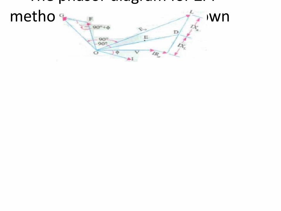
- The phasor diagram for ZPF method at a lagging pf is shown
MODULE III
Theory of Salient pole machine – Blondel’s two reaction theory, phasor diagram, Slip test Parallel operation of Alternators – necessity,
methods of synchronizationEffect of changing excitation of
Alternators, load sharing of two Alternators in parallel
Blondel’s two reaction theory- In a cylindrical rotor machine, air gap is uniform & therefore air
gap reactance (reluctance) remains same irrespective of rotor position
- The effect of armature reaction, fluxes & voltage induced can therefore be treated in a simple way with concept of synchronous reactance. It is taken as constant for all positions of field poles
- In a salient pole machine, the air gap is not uniform & therefore reactance (reluctance) of air gap is not a constant.
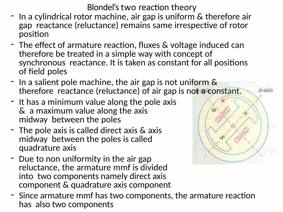
- It has a minimum value along the pole axis & a maximum value along the axis midway between the poles
- The pole axis is called direct axis & axis midway between the poles is called quadrature axis
- Due to non uniformity in the air gap reluctance, the armature mmf is divided into two components namely direct axis component & quadrature axis component
- Since armature mmf has two components, the armature reaction has also two components
- i.e, Direct axis armature reaction reactance (Xad) & Quadrature axis armature reaction reactance (Xaq)
- Similarly armature current has also two components Id & Iq
- Synchronous reactance also has two components Xd & Xq
- Assume that the armature leakage reactance (XL) be constant along both axis
- Direct axis synchronous reactance, Xd = Xad + XL
Quadrature axis synchronous reactance, Xq = Xaq +
XL
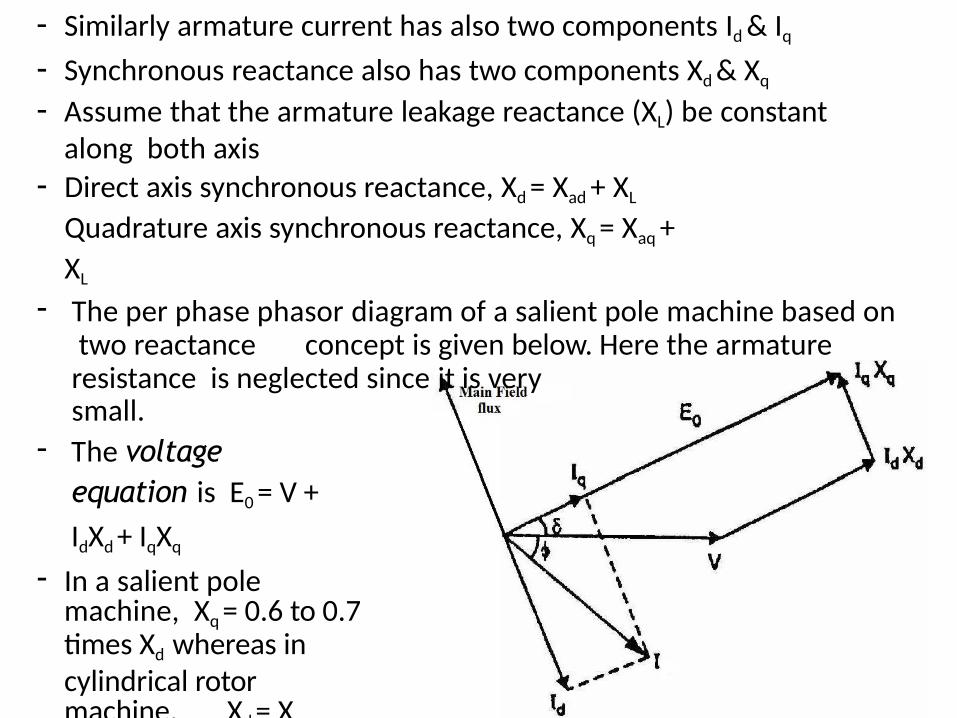
- The per phase phasor diagram of a salient pole machine based on two reactance concept is given below. Here the armature resistance is neglected since it is verysmall.
- The voltage equation is E0 = V +
IdXd + IqXq
- In a salient pole machine, Xq = 0.6 to 0.7 times Xd whereas in cylindrical rotor machine, Xd = Xq
- Angle δ is called power
angle or torque angle
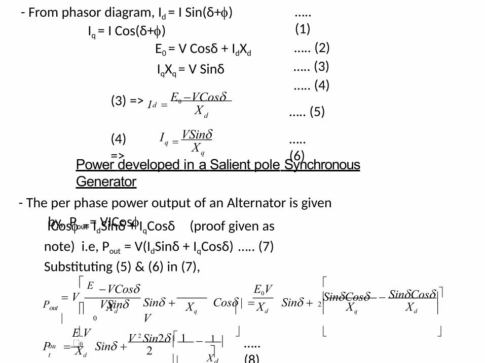
- From phasor diagram, Id = I Sin(δ+)
Iq = I Cos(δ+)
….. (1)
….. (2)
….. (3)
….. (4)
….. (5)
E0 = V Cosδ + IdXd
IqXq = V Sinδ
d
d(3) => I X E0 VCos
(4) =>
….. (6)
Power developed in a Salient pole Synchronous Generator
- The per phase power output of an Alternator is given
by, Pout = VICos
q
q X
ICos = IdSinδ + IqCosδ (proof given as
note) i.e, Pout = V(IdSinδ + IqCosδ) ….. (7)
Substituting (5) & (6) in (7),
VSinI
…..(8)
SinCos
out Xd
Xq
Xd
XdXqXdXqXd
V
Pout
E V 1
V 2 Sin2 1P 0 Sin
E0V E
0
SinCos
2Sin Cos Sin V
VCosVSin
2
- Equation (8) gives power
developed per phase. Total
power developed is three
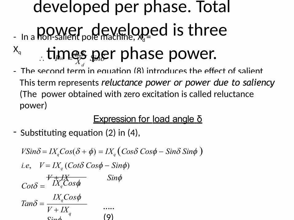
times per phase power.- In a non-salient pole machine, Xd =
Xq
- The second term in equation (8) introduces the effect of salient poles.
X dout P E0V Sin
q
IXqCos
IXqCos
V IXSin
Tan
This term represents reluctance power or power due to saliency (The power obtained with zero excitation is called reluctance power)
Expression for load angle δ- Substituting equation (2) in (4),
VSin IXqCos( ) IXq Cos Cos Sin Sin i.e, V IXq (Cot Cos Sin)
V IX SinCot q
…..(9)
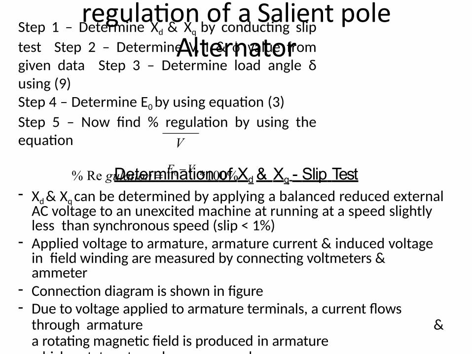
Determination of % voltage regulation of a Salient pole
Alternator
Determination of Xd & Xq - Slip Test- Xd & Xq can be determined by applying a balanced reduced external
AC voltage to an unexcited machine at running at a speed slightly less than synchronous speed (slip < 1%)
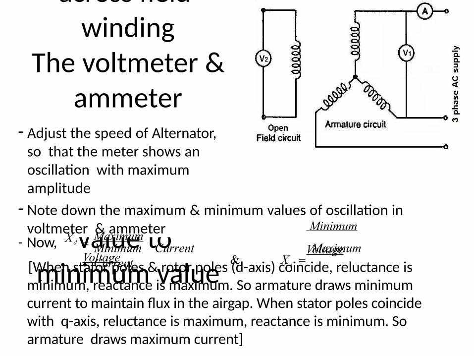
- Applied voltage to armature, armature current & induced voltage in field winding are measured by connecting voltmeters & ammeter
- Connection diagram is shown in figure- Due to voltage applied to armature terminals, a current flows
through armature & a rotating magnetic field is produced in armaturewhich rotates at synchronous speed
V
Step 1 – Determine Xd & Xq by conducting slip
test Step 2 – Determine V, I & value from given data Step 3 – Determine load angle δ using (9)Step 4 – Determine E0 by using equation (3)
Step 5 – Now find % regulation by using the equation
% Re gulation E0 V *100%
in armature circuit show an
- When field rotates, it will
cut flux lines & EMF induces across field
windingThe voltmeter &
ammeter connected
oscillation from a maximum
value to minimum value
- Adjust the speed of Alternator, so that the meter shows an oscillation with maximum amplitude
- Note down the maximum & minimum values of oscillation in voltmeter & ammeter
- Now,
[When stator poles & rotor poles (d-axis) coincide, reluctance is minimum, reactance is maximum. So armature draws minimum current to maintain flux in the airgap. When stator poles coincide with q-axis, reluctance is maximum, reactance is minimum. So armature draws maximum current]
Minimum Current MaximumCurrent
Xd Maximum
Voltage
Minimum
Voltage& Xq
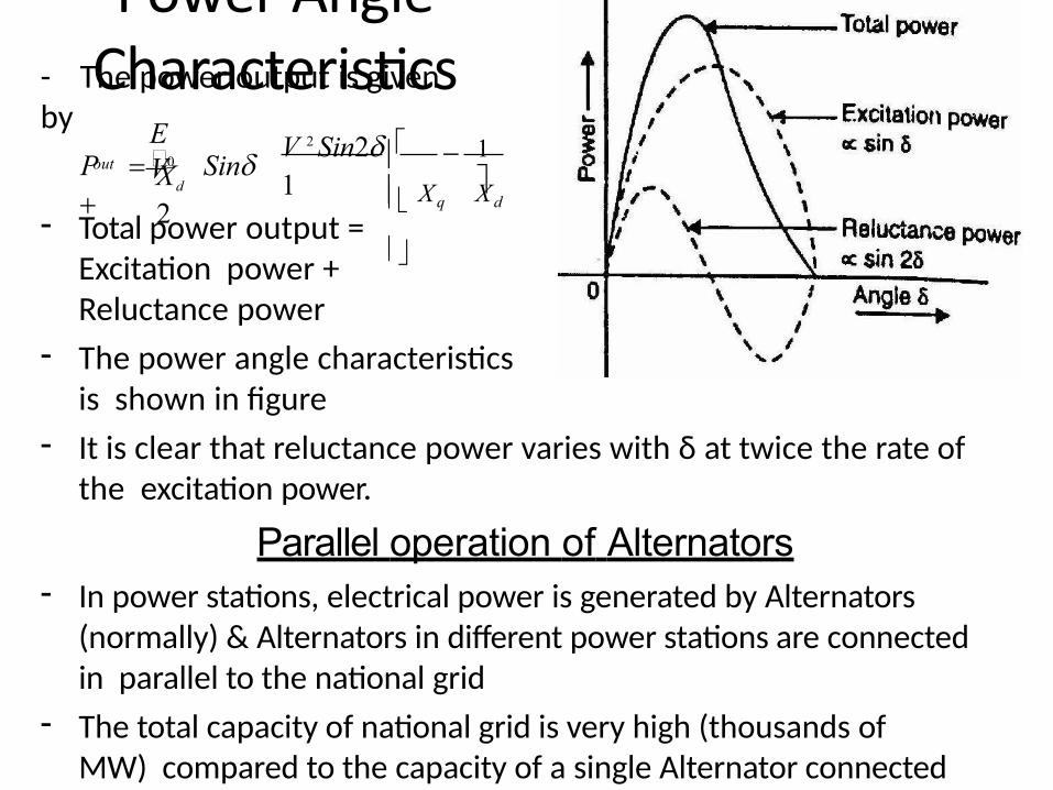
Power Angle Characteristics- The power output is given
by
out
X q X d
E V
1Xd
2
V 2 Sin2
1P 0 Sin
- Total power output = Excitation power + Reluctance power
- The power angle characteristics is shown in figure
- It is clear that reluctance power varies with δ at twice the rate of the excitation power.
Parallel operation of Alternators- In power stations, electrical power is generated by Alternators
(normally) & Alternators in different power stations are connected in parallel to the national grid
- The total capacity of national grid is very high (thousands of MW) compared to the capacity of a single Alternator connected to it
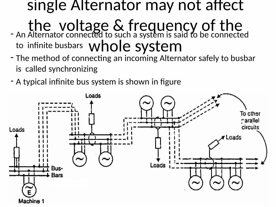
- Therefore the performance of a single Alternator may not affect the voltage & frequency of the
whole system- An Alternator connected to such a system is said to be connected
to infinite busbars
- The method of connecting an incoming Alternator safely to busbar is called synchronizing
- A typical infinite bus system is shown in figure
Advantages of parallel operation of Alternators1.Continuity of service - The continuity of service is one of the
important requirements of any electrical system. If one alternator fails, the continuity of supply can be maintained through the other healthy units. This will ensure uninterrupted supply to the consumers.
2. Efficiency - Alternators give maximum efficiency when delivering full- load power output. The load on the power system varies during the whole day, being maximum during peak hours (6 pm to 10 pm) & minimum during off peak hours (10 pm to 6 am). So to get maximum efficiency, units can be added or put off depending upon the load requirement. This permits the efficient operation of the power system.
3. Maintenance & repair – Alternators require routine maintenance & repair. During maintenance & repair, continuity of supply can be ensured from other units
4. Load growth – The load demand is increasing day by day due to the increased use of electrical power. The load growth can be met by adding more units in parallel, without disturbing the original installation.
Conditions for paralleling an Alternator to infinite bus bar- The method of connecting an incoming Alternator safely to busbar
is called synchronizing
- For synchronizing an Alternator to an infinite busbar, the following conditions are to be satisfied
1. The terminal voltage (r.m.s. value) of the incoming alternator must be the same as busbars voltage.
2. The frequency of the generated voltage of the incoming alternator must be equal to the busbars frequency.
3. The phase of the incoming alternator voltage must be identical with the phase of the busbars voltage. In other words, the two voltages must be in phase with each other.
4. The phase sequence (RYB or RBY) of the voltage of the incoming alternator should be the same as that of the busbars.
- The condition 1 is indicated by a voltmeter, conditions 2&3 are indicated by a synchronizing lamp arrangement or a synchroscope. The condition 4 is indicated by a phase sequence indicator
Methods of synchronization- The equality of voltage between incoming Alternator & busbar can
be checked by using a voltmeter. If they are different, then terminal voltage of Alternator is made equal to busbar voltage by varying its field excitation
- The phase sequence of the alternator & the busbars can be checked by a phase sequence indicator. If they are different, change phase sequence of Alternator so that both are having same phase sequence
- The difference in frequency & phase of the voltages of the incoming alternator & busbars can be checked by one of the following two methods:
(i) By using a synchronizing Lamp arrangement
(ii) By using a synchroscope
(i) By using a synchronizing Lamp arrangement- There are 2 type of synchronizing lamp arrangement
1. 3 dark lamp method or dark lamp method
2. 2 bright & 1 dark lamp method or bright lamp method
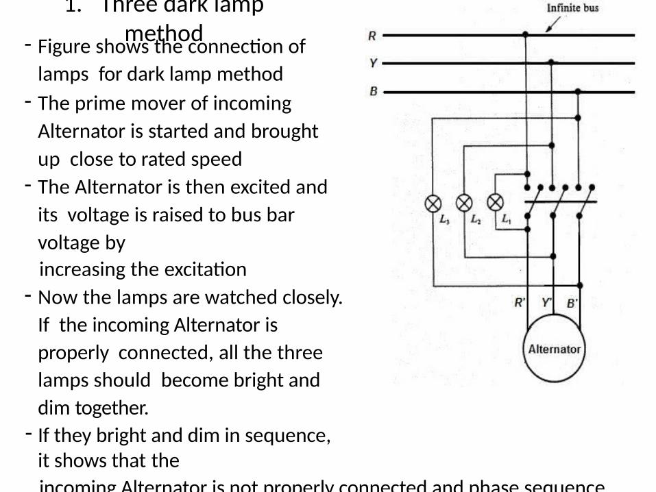
1. Three dark lamp method- Figure shows the connection of
lamps for dark lamp method
- The prime mover of incoming
Alternator is started and brought
up close to rated speed- The Alternator is then excited and
its voltage is raised to bus bar
voltage by
increasing the excitation- Now the lamps are watched closely.
If the incoming Alternator is
properly connected, all the three
lamps should become bright and
dim together.- If they bright and dim in sequence,
it shows that the
incoming Alternator is not properly connected and phase sequence
of incoming Alternator must be reversed for synchronization

- The speed of the prime mover of incoming machine is further adjusted until the lamps flicker at a very low rate (less than one dark period per second)
- The voltage of incoming machine is again adjusted and the paralleling switch is closed at the instant all the three lamps are dark
Disadvantage of this method- The lamps go dark at somewhat less than half their rated voltage
and so the paralleling switch might be closed when there is a considerable voltage exists across the switch & this may damage the machines.
- Another disadvantage is that the lamp filaments might burn out.
- Third disadvantage is that the flicker of lamps does not indicate whether the incoming machine is slow or fast
- These difficulties are eliminated in two bright and one dark lamp method.
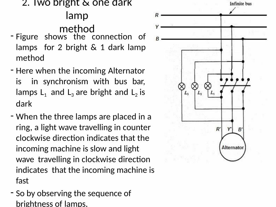
2. Two bright & one dark lamp
method- Figure shows the connection of
lamps for 2 bright & 1 dark lamp method
- Here when the incoming Alternator is in synchronism with bus bar, lamps L1 and L3 are bright and L2 is
dark
- When the three lamps are placed in a ring, a light wave travelling in counter clockwise direction indicates that the incoming machine is slow and light wave travelling in clockwise direction indicates that the incoming machine is fast
- So by observing the sequence of brightness of lamps,it can be determined whether incoming machine is fast or slow
- The paralleling switch is closed when the change in light are slow and at the instant the lamp connected directly across one phase is dark
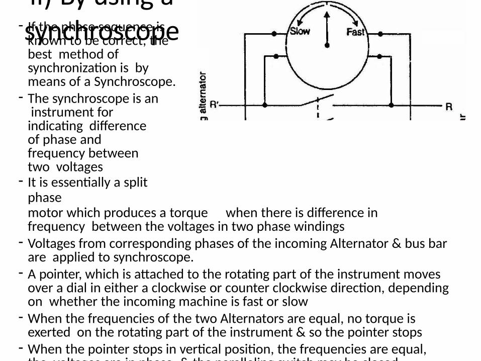
ii) By using a synchroscope- If the phase sequence is known to be correct, the best method of synchronization is by means of a Synchroscope.
- The synchroscope is an instrument for indicating difference of phase and frequency between two voltages
- It is essentially a split phasemotor which produces a torque when there is difference in frequency between the voltages in two phase windings
- Voltages from corresponding phases of the incoming Alternator & bus bar are applied to synchroscope.
- A pointer, which is attached to the rotating part of the instrument moves over a dial in either a clockwise or counter clockwise direction, depending on whether the incoming machine is fast or slow
- When the frequencies of the two Alternators are equal, no torque is exerted on the rotating part of the instrument & so the pointer stops
- When the pointer stops in vertical position, the frequencies are equal, the voltages are in phase, & the paralleling switch may be closed.
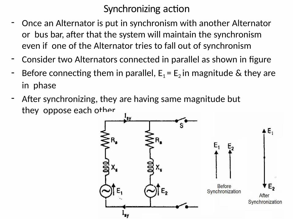
Synchronizing action- Once an Alternator is put in synchronism with another Alternator
or bus bar, after that the system will maintain the synchronism even if one of the Alternator tries to fall out of synchronism
- Consider two Alternators connected in parallel as shown in figure
- Before connecting them in parallel, E1 = E2 in magnitude & they are
in phase
- After synchronizing, they are having same magnitude but they oppose each other
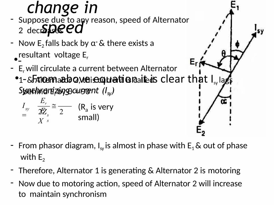
a)Effect of change in
speed- Suppose due to any reason, speed of Alternator
2 decreases
- Now E2 falls back by α◦ & there exists a
resultant voltage Er
- Er will circulate a current between Alternator
1 & Alternator 2, this current is called Synchronizing current (Isy)
a(R is very small)
•-
• - From above equation it is clear that Isy lags
behind Er by θ ≈ 90◦
ss
sy
Er
Er2Z 2 X
I
- From phasor diagram, Isy is almost in phase with E1 & out of phase
with E2
- Therefore, Alternator 1 is generating & Alternator 2 is motoring
- Now due to motoring action, speed of Alternator 2 will increase to maintain synchronism
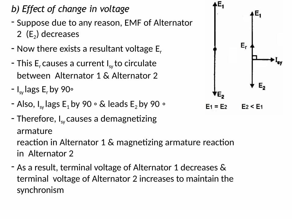
b) Effect of change in voltage- Suppose due to any reason, EMF of Alternator
2 (E2) decreases
- Now there exists a resultant voltage Er
- This Er causes a current Isy to circulate
between Alternator 1 & Alternator 2
- Isy lags Er by 90◦
- Also, Isy lags E1 by 90 ◦ & leads E2 by 90 ◦
- Therefore, Isy causes a demagnetizing
armaturereaction in Alternator 1 & magnetizing armature reaction in Alternator 2
- As a result, terminal voltage of Alternator 1 decreases & terminal voltage of Alternator 2 increases to maintain the synchronism
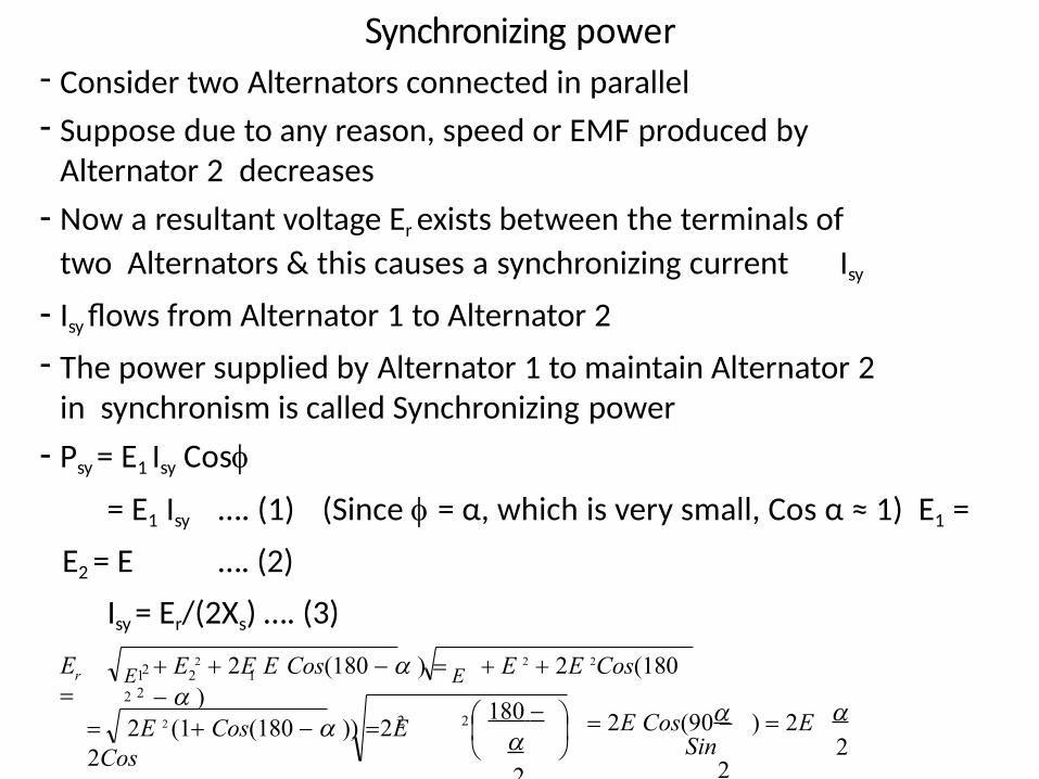
Synchronizing power- Consider two Alternators connected in parallel
- Suppose due to any reason, speed or EMF produced by Alternator 2 decreases
- Now a resultant voltage Er exists between the terminals of
two Alternators & this causes a synchronizing current Isy
- Isy flows from Alternator 1 to Alternator 2
- The power supplied by Alternator 1 to maintain Alternator 2 in synchronism is called Synchronizing power
- Psy = E1 Isy Cos
= E1 Isy …. (1) (Since = α, which is very small, Cos α ≈ 1) E1 =
E2 = E …. (2)
Isy = Er/(2Xs) …. (3)
22
1 2 12
2
E 2 E 2
r
2E Cos(90 ) 2E Sin
2
180
2
2E 2 (1 Cos(180 )) 2E2Cos
E 2 2E E Cos(180 ) E 2 2E 2Cos(180 )
E
i.e, E
…. (4) (Since α is very small, Sin(α/2)
=α/2)
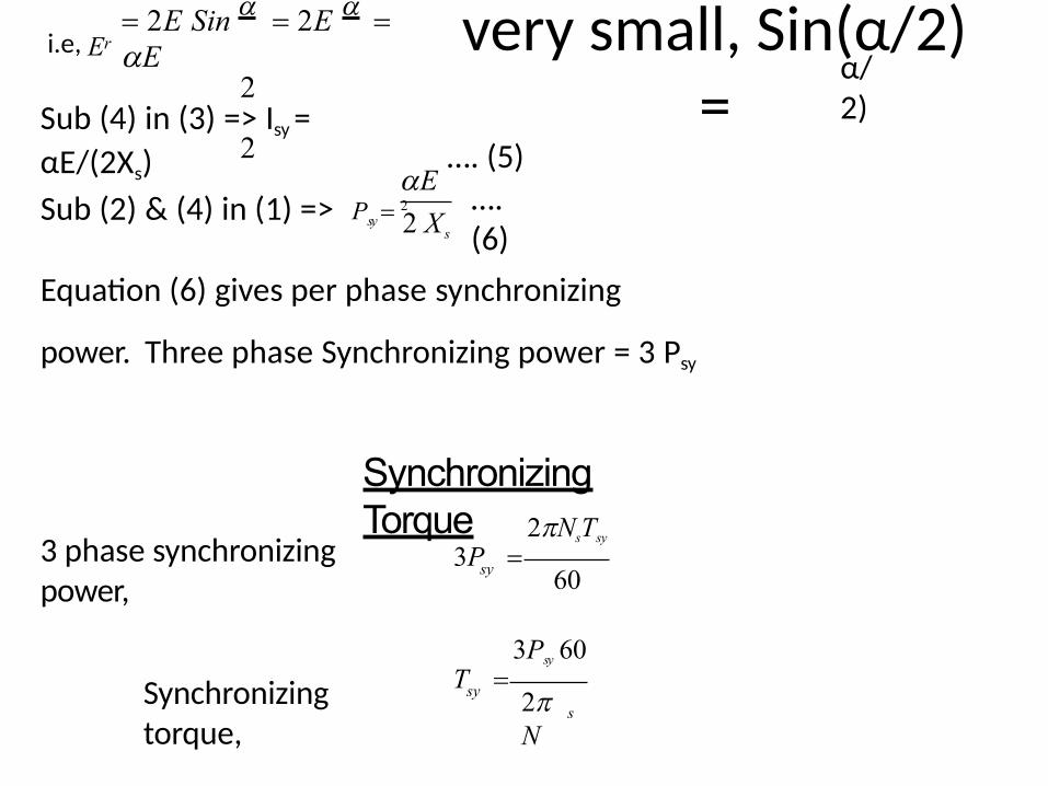
…. (5)Sub (4) in (3) => Isy =
αE/(2Xs)…. (6)
2E Sin 2E E
2
2
r
2 X s
E 2Sub (2) & (4) in (1) => Psy
Equation (6) gives per phase synchronizing
power. Three phase Synchronizing power = 3 Psy
Synchronizing Torque
3 phase synchronizing power,
Synchronizing torque,
ssy
sy
2N
3Psy 60T
60
2NsTsy
3P
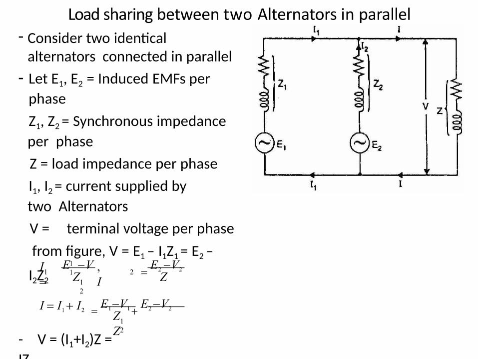
Load sharing between two Alternators in parallel- Consider two identical
alternators connected in parallel
- Let E1, E2 = Induced EMFs per
phase
Z1, Z2 = Synchronous impedance
per phase
Z = load impedance per phase
I1, I2 = current supplied by
two Alternators
V = terminal voltage per phase
from figure, V = E1 – I1Z1 = E2 –
I2Z2
- V = (I1+I2)Z =
IZ
12
2
12
111
ZZ
Z,IZ
E1 V1
E2 V2I I1 I2
E V E2 V2I
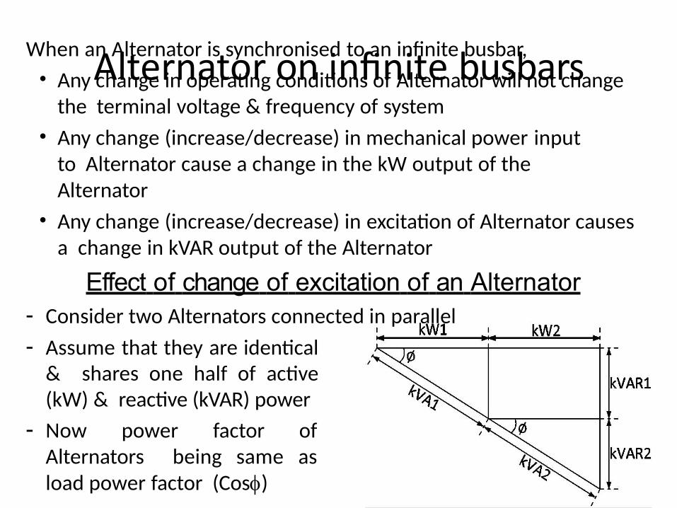
Alternator on infinite busbarsWhen an Alternator is synchronised to an infinite busbar,
• Any change in operating conditions of Alternator will not change the terminal voltage & frequency of system
• Any change (increase/decrease) in mechanical power input to Alternator cause a change in the kW output of the Alternator
• Any change (increase/decrease) in excitation of Alternator causes a change in kVAR output of the Alternator
Effect of change of excitation of an Alternator- Consider two Alternators connected in parallel
- Assume that they are identical & shares one half of active (kW) & reactive (kVAR) power
- Now power factor of Alternators being same as load power factor (Cos)
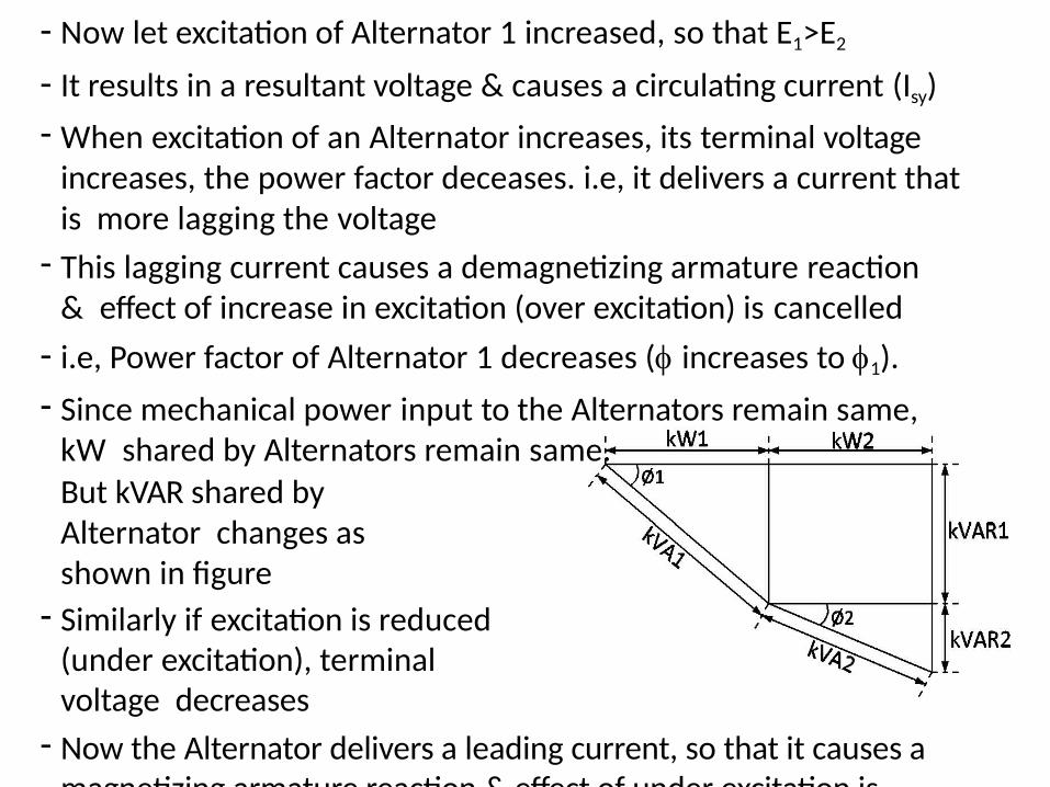
- Now let excitation of Alternator 1 increased, so that E1>E2
- It results in a resultant voltage & causes a circulating current (Isy)
- When excitation of an Alternator increases, its terminal voltage increases, the power factor deceases. i.e, it delivers a current that is more lagging the voltage
- This lagging current causes a demagnetizing armature reaction & effect of increase in excitation (over excitation) is cancelled
- i.e, Power factor of Alternator 1 decreases ( increases to 1).
- Since mechanical power input to the Alternators remain same, kW shared by Alternators remain same.
But kVAR shared by Alternator changes as shown in figure
- Similarly if excitation is reduced (under excitation), terminal voltage decreases
- Now the Alternator delivers a leading current, so that it causes a magnetizing armature reaction & effect of under excitation is cancelled
MODULE IV
Synchronous motor – Construction, Principle of
operation, Effect of excitation on armature current
& power factor, V & inverted V curve, Phasor
diagram, Losses & efficiency
Three phase induction motor – Constructional
features, Types, Theory, Slip, Mechanical power
& torque developed, Torque slip characteristics,
Equivalent circuit93
Synchronous motor
- A synchronous motor is an electrical machine which converts AC
electrical energy into mechanical energy
- A synchronous motor runs at synchronous speed, Ns = (120f)/P
Construction of Synchronous motor
- It has mainly 2 parts
1. Stator
2. Rotor
94
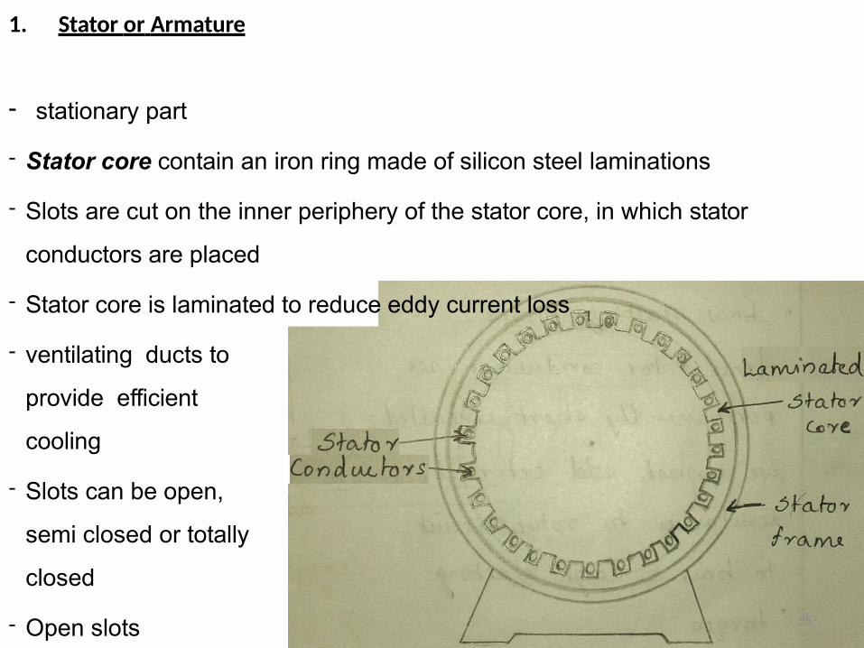
1. Stator or Armature
- stationary part
- Stator core contain an iron ring made of silicon steel laminations
- Slots are cut on the inner periphery of the stator core, in which stator
conductors are placed
- Stator core is laminated to reduce eddy current loss
- ventilating ducts to
provide efficient
cooling
- Slots can be open,
semi closed or totally
closed
- Open slots 95
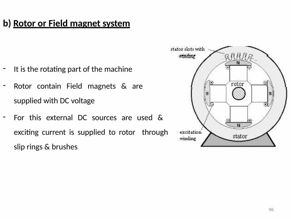
b) Rotor or Field magnet system
- It is the rotating part of the machine
- Rotor contain Field magnets & are
supplied with DC voltage
- For this external DC sources are used &
exciting current is supplied to rotor through
slip rings & brushes
96
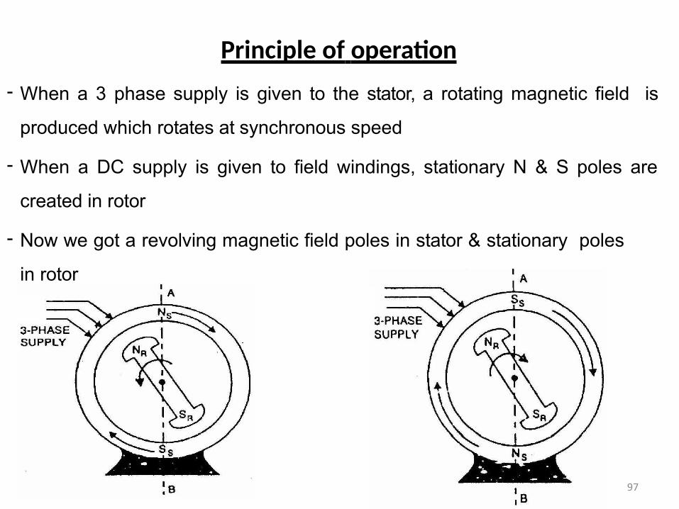
Principle of operation
- When a 3 phase supply is given to the stator, a rotating magnetic field is
produced which rotates at synchronous speed
- When a DC supply is given to field windings, stationary N & S poles are
created in rotor
- Now we got a revolving magnetic field poles in stator & stationary poles
in rotor
97
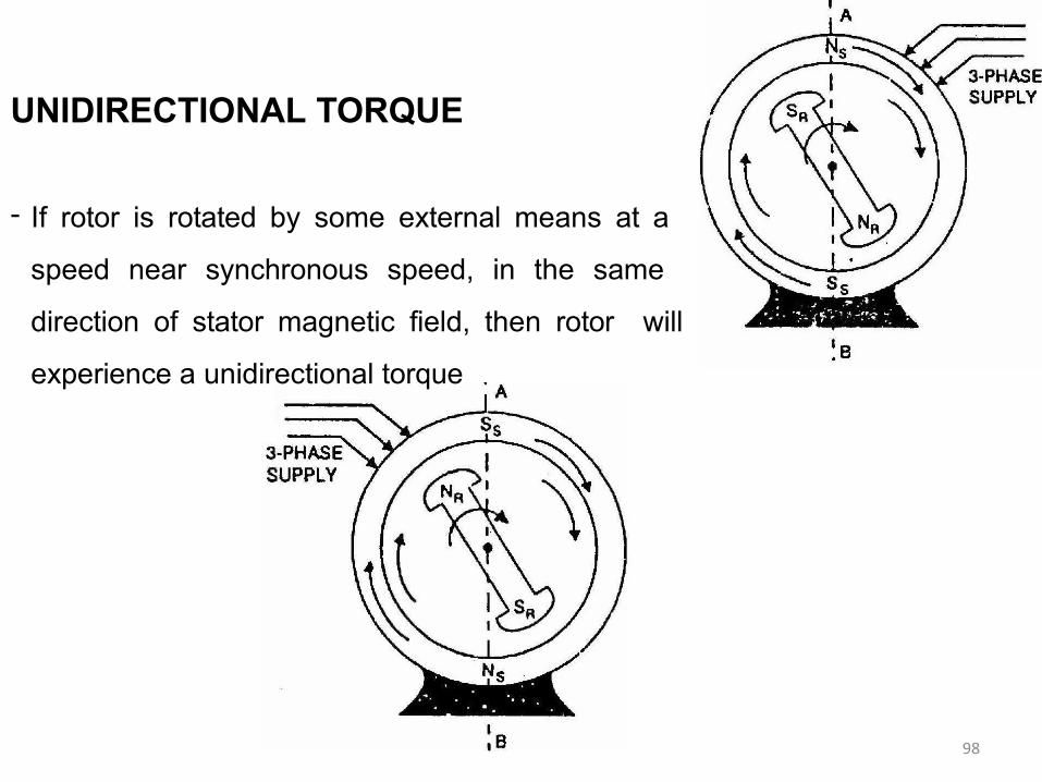
UNIDIRECTIONAL TORQUE
- If rotor is rotated by some external means at a
speed near synchronous speed, in the same
direction of stator magnetic field, then rotor will
experience a unidirectional torque
98
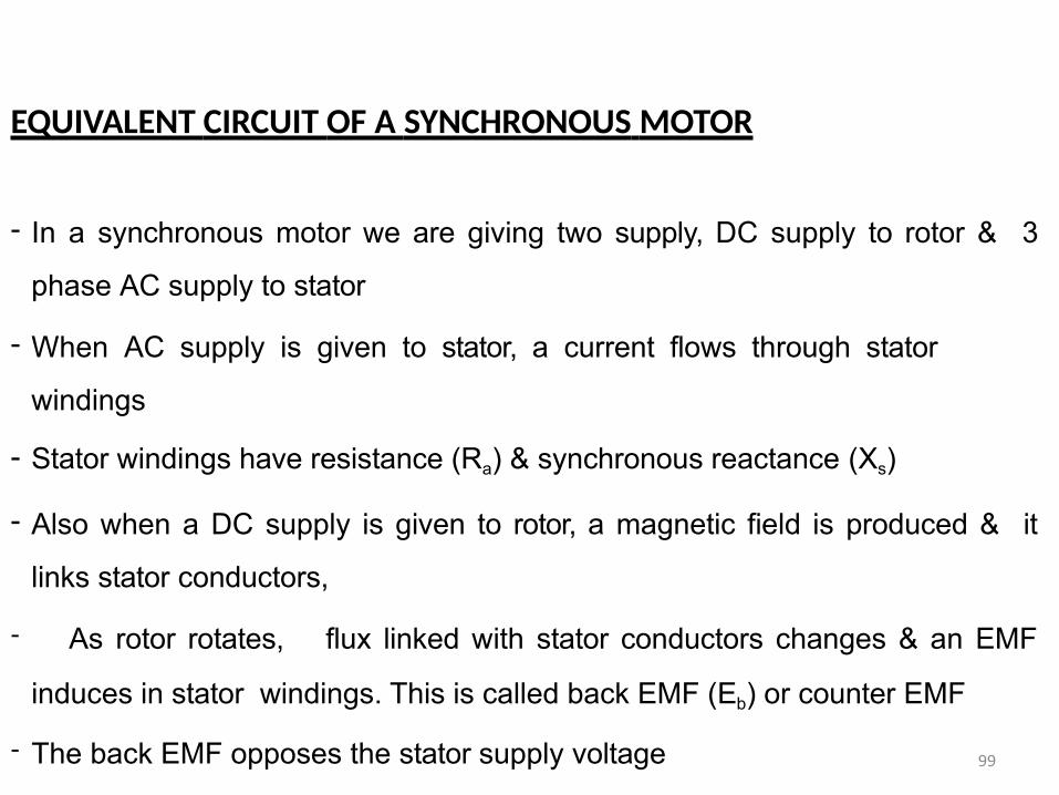
EQUIVALENT CIRCUIT OF A SYNCHRONOUS MOTOR
- In a synchronous motor we are giving two supply, DC supply to rotor & 3
phase AC supply to stator
- When AC supply is given to stator, a current flows through stator
windings
- Stator windings have resistance (Ra) & synchronous reactance (Xs)
- Also when a DC supply is given to rotor, a magnetic field is produced & it
links stator conductors,
- As rotor rotates, flux linked with stator conductors changes & an EMF
induces in stator windings. This is called back EMF (Eb) or counter EMF
- The back EMF opposes the stator supply voltage 99
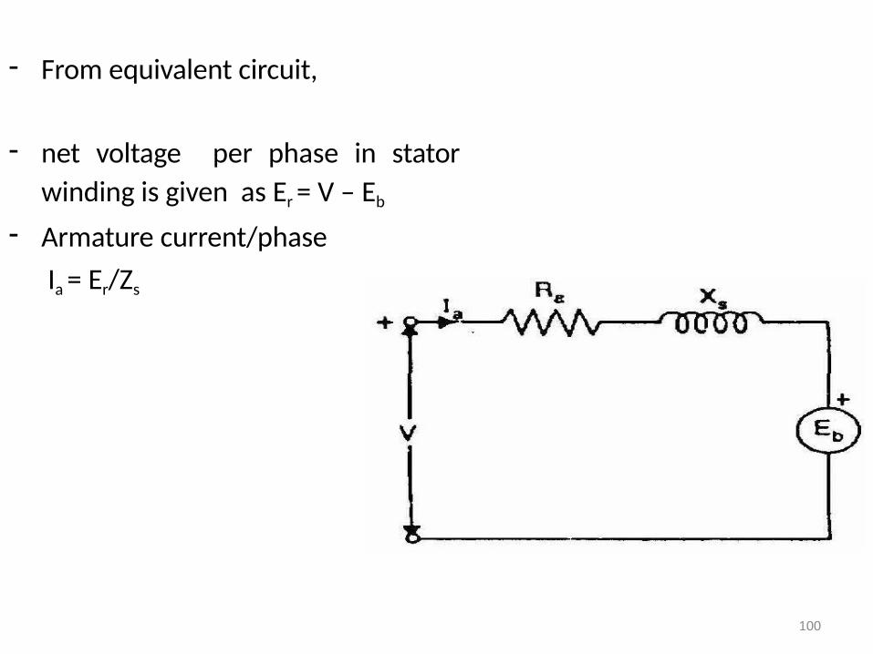
- From equivalent circuit,
- net voltage per phase in stator
winding is given as Er = V – Eb
- Armature current/phase
Ia = Er/Zs
100
STARTING METHODS OF SYNCHRONOUS MOTOR
- Synchronous motor has no self starting torque
- 1. From DC source
- If a DC supply & a DC motor (shunt/compound) is available, the Synchronous
motor is coupled to DC motor & is started using DC motor
2. By using an AC motor
- a small AC induction motor is used for starting the Synchronous motor
3. By providing damper windings
- Synchronous motor can be made self starting by providing a special winding
on rotor poles known as damper winding or squirrel cage winding
- Damper winding consist of short circuited copper bars placed in rotor poles
- When AC supply is given to stator, the synchronous motor will start as an
Induction motor & rotates at a speed near synchronous speed101
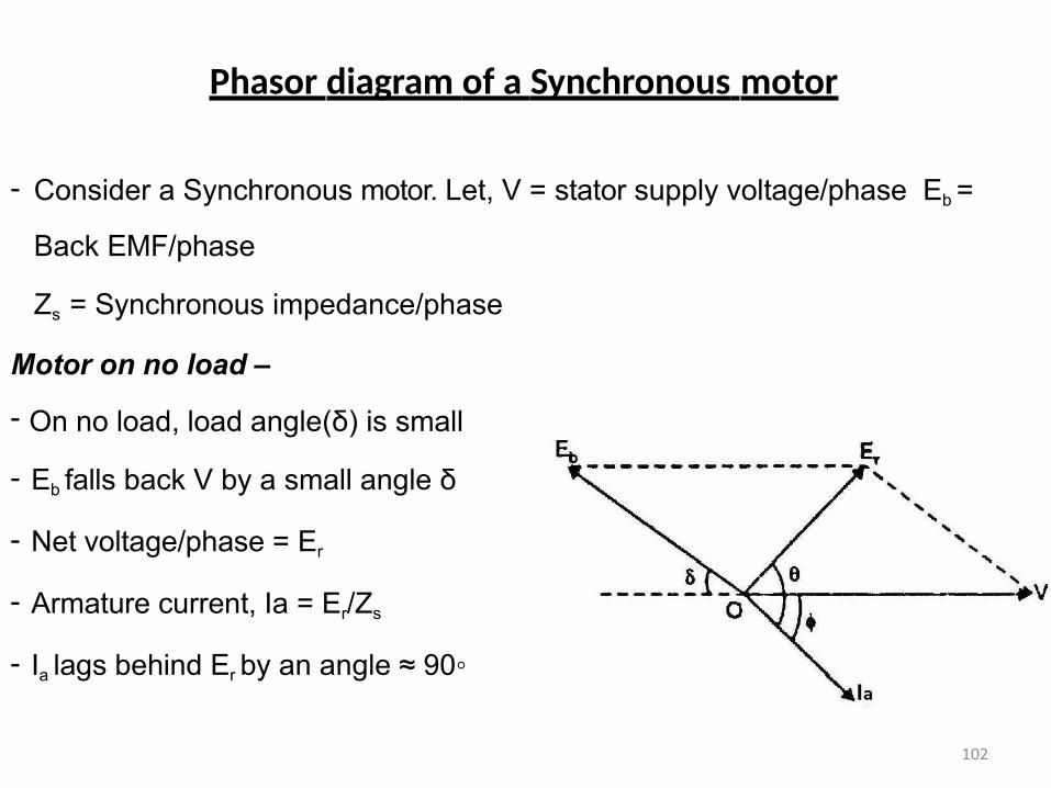
Phasor diagram of a Synchronous motor
- Consider a Synchronous motor. Let, V = stator supply voltage/phase Eb =
Back EMF/phase
Zs = Synchronous impedance/phase
Motor on no load –
- On no load, load angle(δ) is small
- Eb falls back V by a small angle δ
- Net voltage/phase = Er
- Armature current, Ia = Er/Zs
- Ia lags behind Er by an angle ≈ 90◦
102
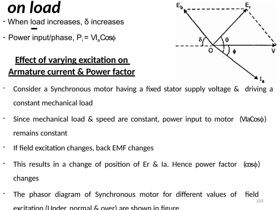
Motor on load
–- When load increases, δ increases
- Power input/phase, Pi = VIaCos
Effect of varying excitation on
Armature current & Power factor
- Consider a Synchronous motor having a fixed stator supply voltage & driving a
constant mechanical load
- Since mechanical load & speed are constant, power input to motor (VIaCos)
remains constant
- If field excitation changes, back EMF changes
- This results in a change of position of Er & Ia. Hence power factor (cos)
changes
- The phasor diagram of Synchronous motor for different values of field
excitation (Under, normal & over) are shown in figure103
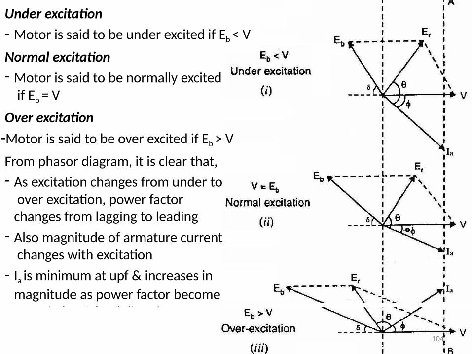
Under excitation
- Motor is said to be under excited if Eb < V
Normal excitation
- Motor is said to be normally excited if Eb = V
Over excitation
-Motor is said to be over excited if Eb > V
From phasor diagram, it is clear that,
- As excitation changes from under to over excitation, power factor changes from lagging to leading
- Also magnitude of armature current changes with excitation
- Ia is minimum at upf & increases in
magnitude as power factor become poor in lag & lead directions
104
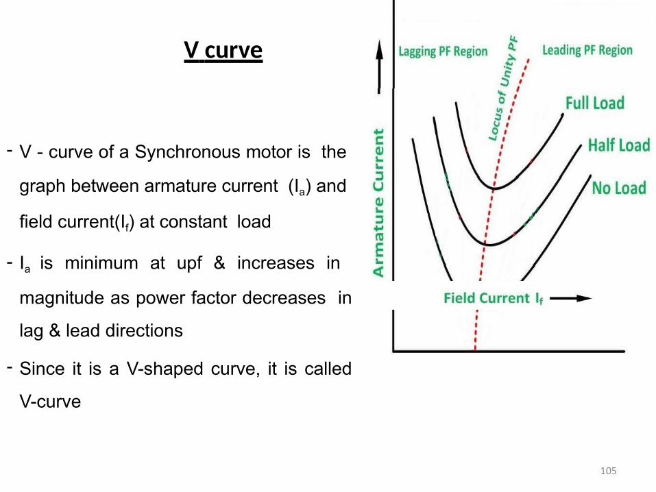
V curve
- V - curve of a Synchronous motor is the
graph between armature current (Ia) and
field current(If) at constant load
- Ia is minimum at upf & increases in
magnitude as power factor decreases in
lag & lead directions
- Since it is a V-shaped curve, it is called
V-curve
105
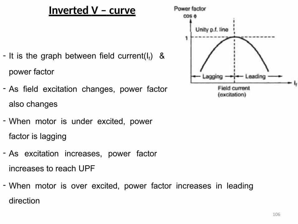
Inverted V – curve
- It is the graph between field current(If) &
power factor
- As field excitation changes, power factor
also changes
- When motor is under excited, power
factor is lagging
- As excitation increases, power factor
increases to reach UPF
- When motor is over excited, power factor increases in leading
direction
106
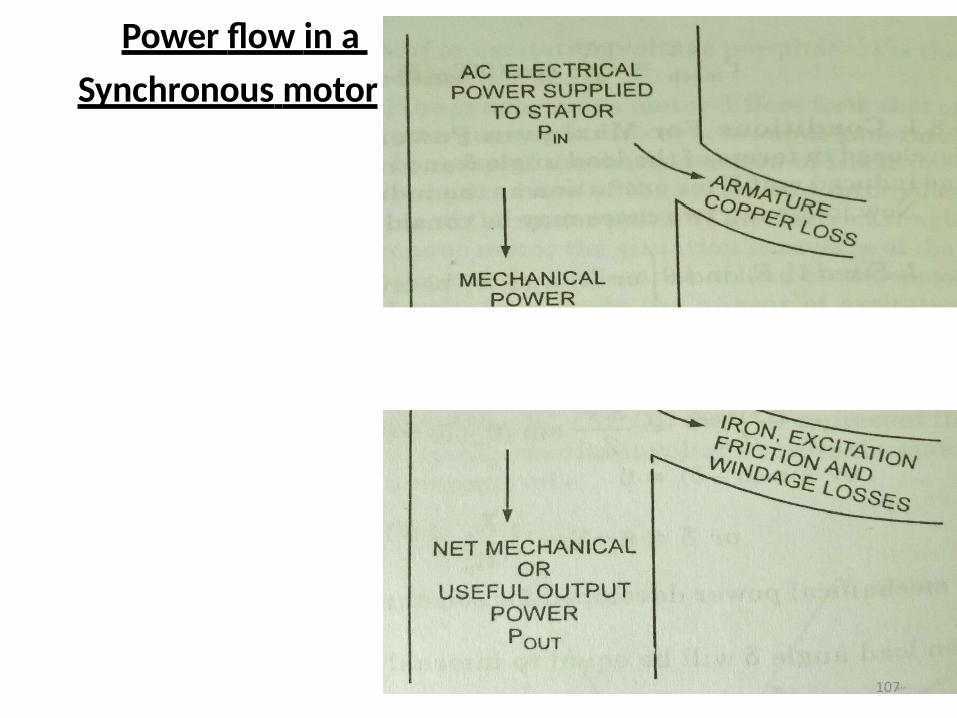
Power flow in a
Synchronous motor
107
Losses & Efficiency of Synchronous motor
Losses in synchronous motor may be divided into two,
a) Load losses
Armature Cu loss
b) Open Circuit losses – These losses present at no load condition. The
open circuit losses are,
1. Frictional losses – losses occurring in the machine due to friction.
2. Windage loss – Losses due to air friction on rotor
3. Iron losses – These are Hysteresis & Eddy current losses in stator &
rotor cores due to varying magnetic flux in the machine
108
Efficiency Mechanical Power Output of Motor
*100%
Electrical Power Input to Stator
Efficiency Electrical Power Input to Stator Losses
*100%
Electrical Power Input to Stator
Different Torques in Synchronous motor
1. Starting torque – This is the torque produced in the motor during
starting.
2. Running torque – Torque produced by motor during running condition
3. Pull in torque – This is the torque produced when motor is pulled into
synchronism when changing from induction to synchronous motor operation
4. Pull out torque – Maximum load torque above which motor will be
pulled out of synchronism is called pull out torque 109
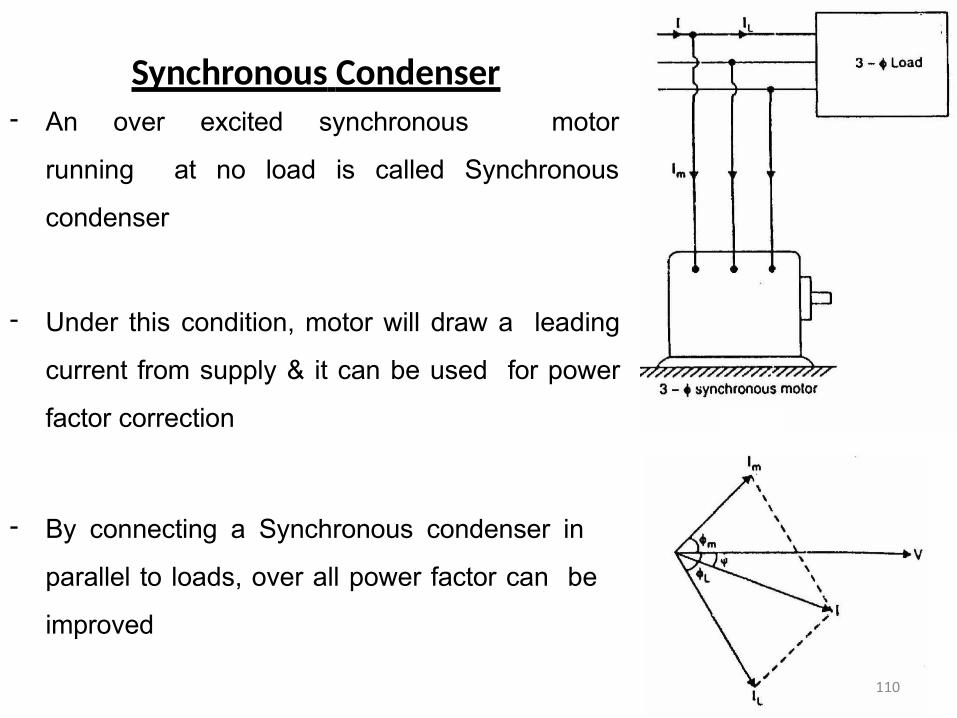
Synchronous Condenser- An over excited synchronous motor
running at no load is called Synchronous
condenser
- Under this condition, motor will draw a leading
current from supply & it can be used for power
factor correction
- By connecting a Synchronous condenser in
parallel to loads, over all power factor can be
improved
110
Three Phase Induction motors
• Three-phase induction motors are the most common machines
in industry.
• Three phase Induction motors are having following advantages
– simple design, rugged, low-price, easy maintenance
– wide range of power ratings: fractional horsepower to 10 MW
– run essentially at constant speed from no-load to full load
– It has high efficiency and reasonably good power factor
– It has self starting torque
• Disadvantages of 3 phase Induction motors are
- Speed control is difficult & requires a variable frequency power
electronic drive for accurate speed control
- Starting torque is inferior to DC shunt motor 111
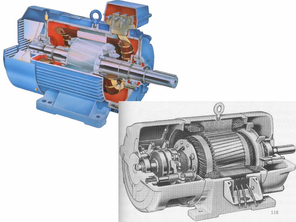
Construction of 3 Phase Induction Motor
An induction motor has two main parts
1. Stator - stationary part
2. Rotor – rotating part
- Stator is separated from rotor by a small air gap ranges from 0.4mm to 4mm,
depending on the power rating of motor
There are two type of 3 phase Induction motor based on the construction of rotor.
a) Squirrel Cage Induction Motor (SCIM) b) Slip Ring Induction Motor (SRIM)
112
-
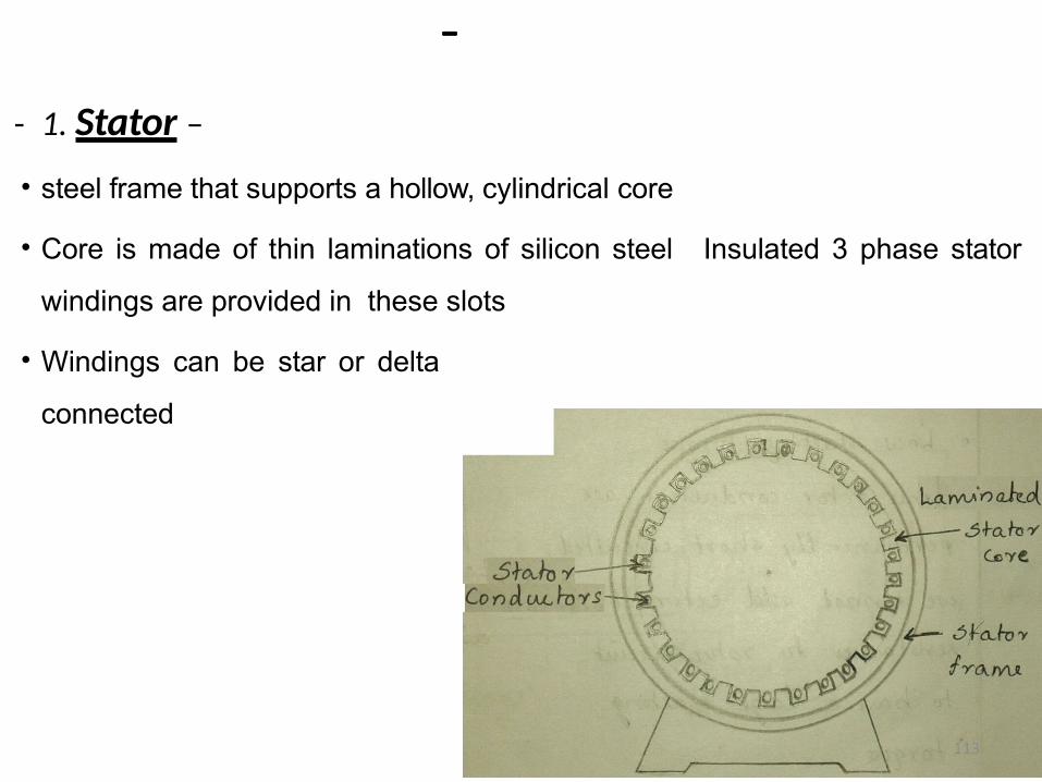
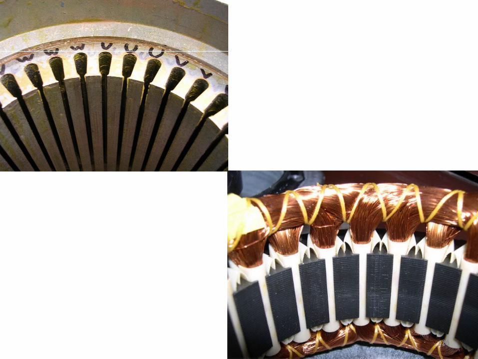
- 1. Stator –
• steel frame that supports a hollow, cylindrical core
• Core is made of thin laminations of silicon steel Insulated 3 phase stator
windings are provided in these slots
• Windings can be star or delta
connected
113
26114
2. Rotor – rotating part
Depending on the construction, there are two type of rotor
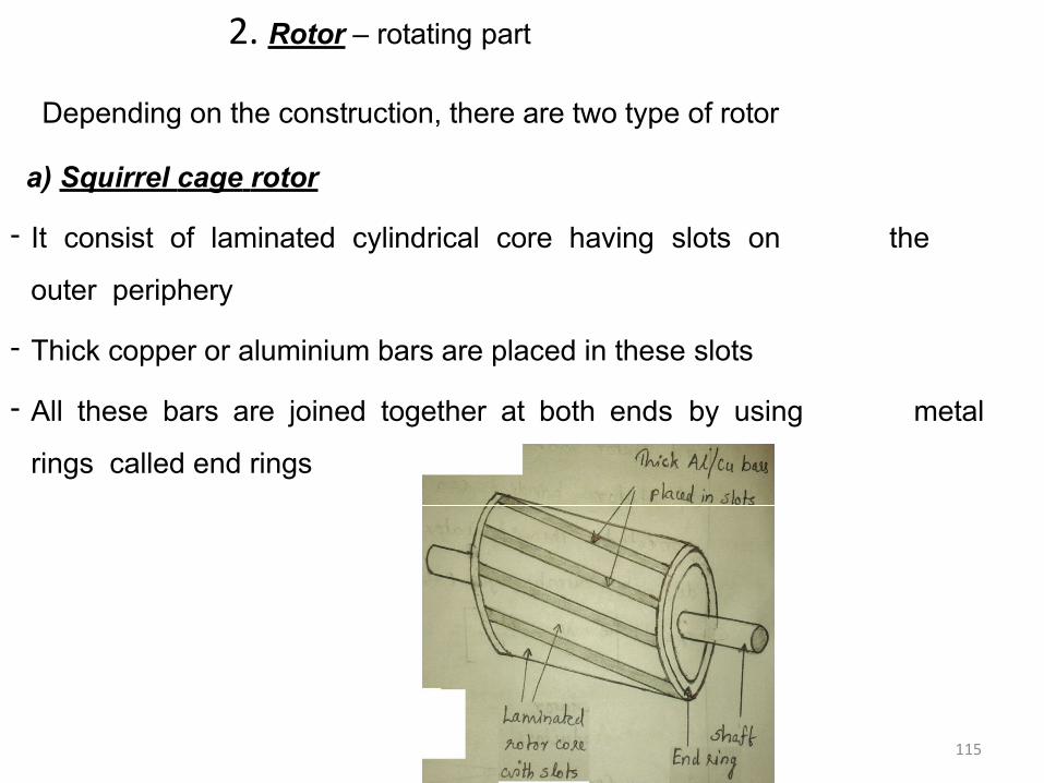
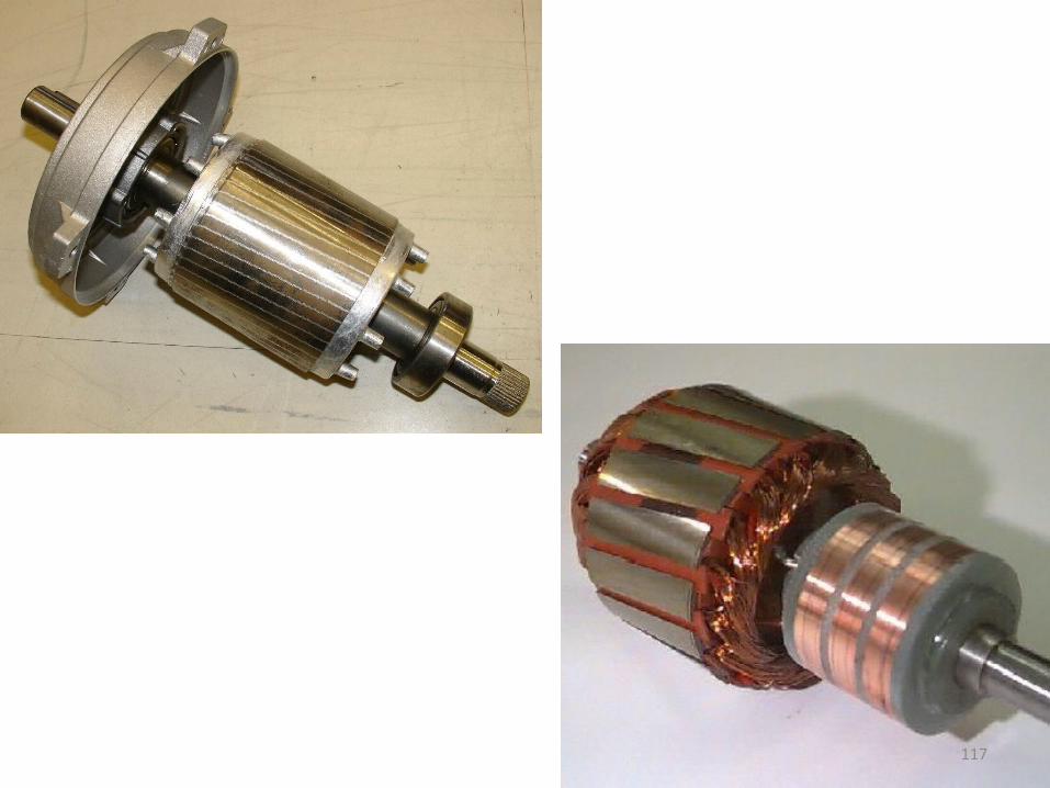
a) Squirrel cage rotor
- It consist of laminated cylindrical core having slots on the
outer periphery
- Thick copper or aluminium bars are placed in these slots
- All these bars are joined together at both ends by using metal
rings called end rings
115
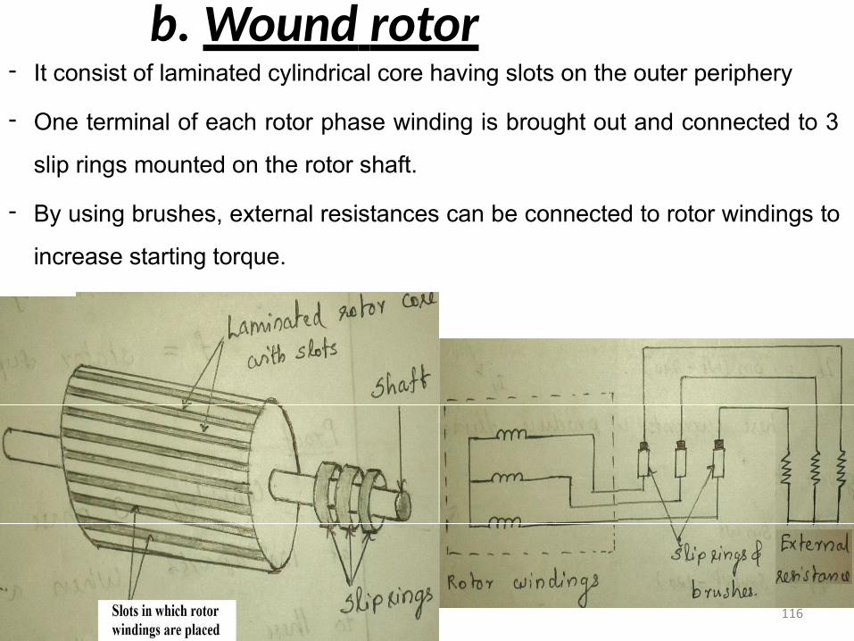
b. Wound rotor- It consist of laminated cylindrical core having slots on the outer periphery
- One terminal of each rotor phase winding is brought out and connected to 3
slip rings mounted on the rotor shaft.
- By using brushes, external resistances can be connected to rotor windings to
increase starting torque.
116
117
118
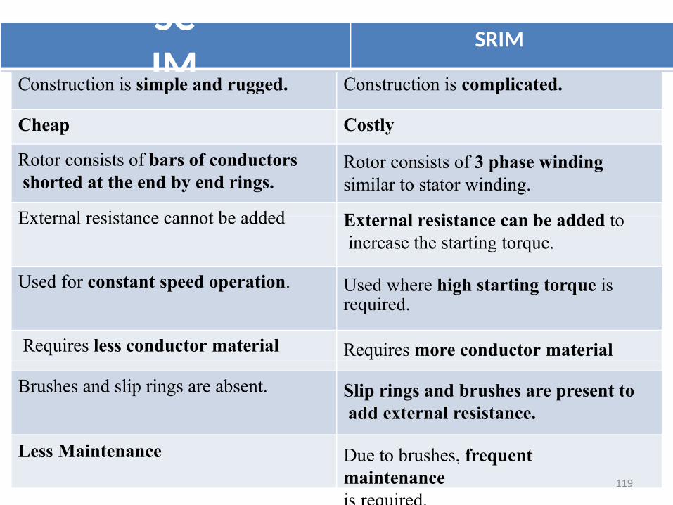
SCIM
SRIM
Costly
required.
Construction is simple and rugged.
Cheap
Rotor consists of bars of conductors shorted at the end by end rings.
External resistance cannot be added
Used for constant speed operation.
Requires less conductor material
Brushes and slip rings are absent.
Less Maintenance
Construction is complicated.
Rotor consists of 3 phase windingsimilar to stator winding.
External resistance can be added to increase the starting torque.
Used where high starting torque is
Requires more conductor material
Slip rings and brushes are present to add external resistance.
Due to brushes, frequent maintenanceis required.
119
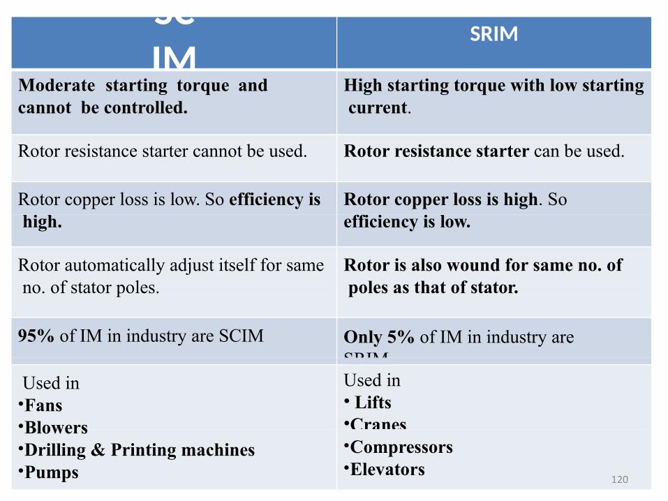
SCIM
SRIM
High starting torque with low starting current.
Rotor resistance starter can be used.
Rotor copper loss is high. Soefficiency is low.
Rotor is also wound for same no. of poles as that of stator.
Only 5% of IM in industry are SRIM.Used in• Lifts•Cranes
Moderate starting torque andcannot be controlled.
Rotor resistance starter cannot be used.
Rotor copper loss is low. So efficiency is high.
Rotor automatically adjust itself for same no. of stator poles.
95% of IM in industry are SCIM
Used in•Fans•Blowers•Drilling & Printing machines•Pumps
•Compressors•Elevators
120
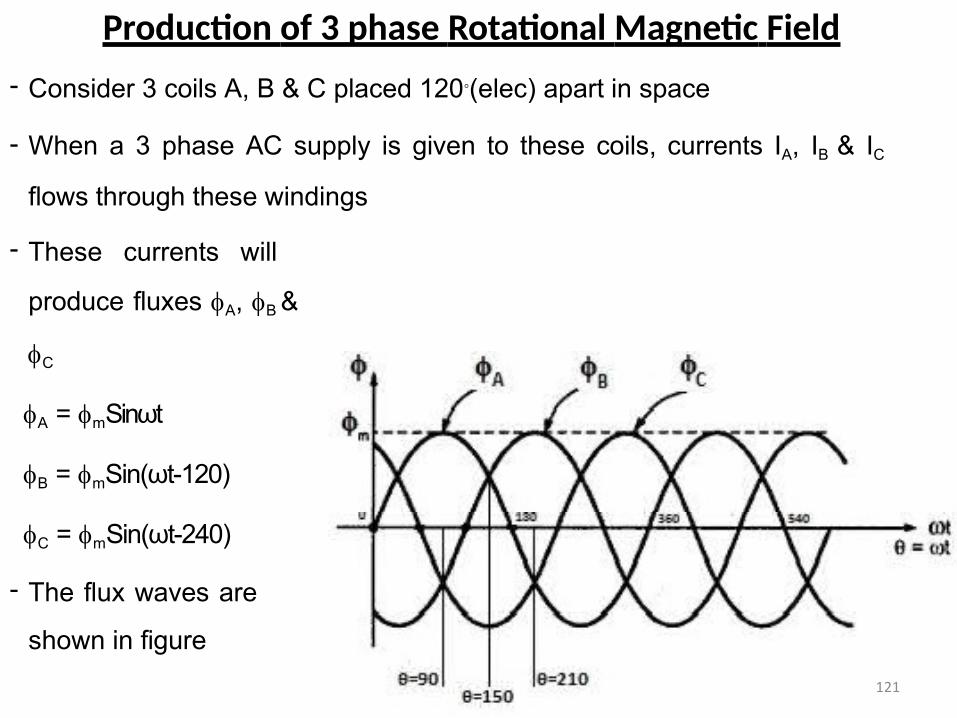
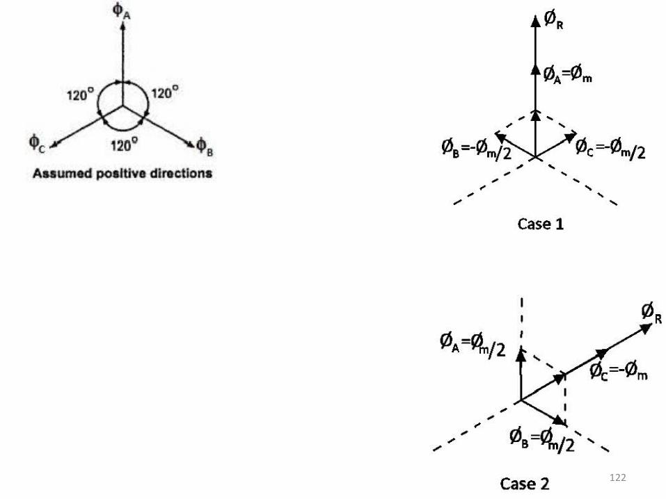
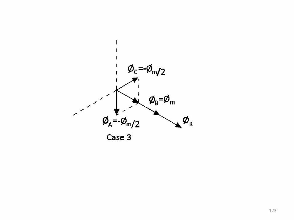
Production of 3 phase Rotational Magnetic Field
- Consider 3 coils A, B & C placed 120◦(elec) apart in space
- When a 3 phase AC supply is given to these coils, currents IA, IB & IC
flows through these windings
- These currents will
produce fluxes A, B &
C
A = mSinωt
B = mSin(ωt-120)
C = mSin(ωt-240)
- The flux waves are
shown in figure
121
122
123
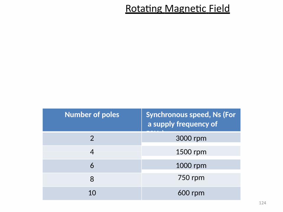
Rotating Magnetic Field
Number of poles Synchronous speed, Ns (For a supply frequency of 50Hz)
2 3000 rpm
4 1500 rpm
6 1000 rpm
8 750 rpm
10 600 rpm124
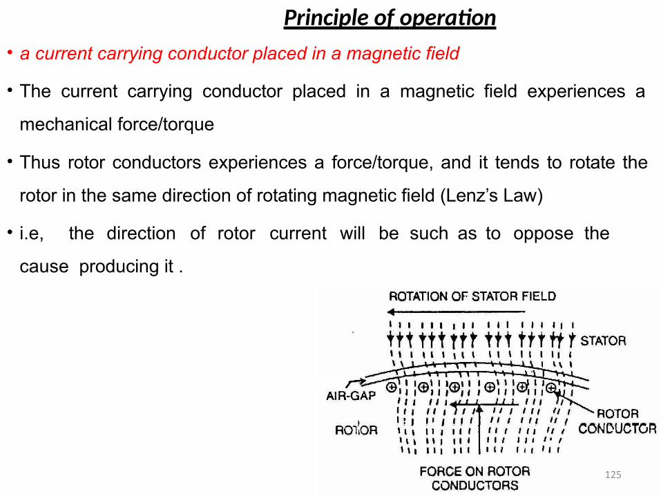
Principle of operation
• a current carrying conductor placed in a magnetic field
• The current carrying conductor placed in a magnetic field experiences a
mechanical force/torque
• Thus rotor conductors experiences a force/torque, and it tends to rotate the
rotor in the same direction of rotating magnetic field (Lenz’s Law)
• i.e, the direction of rotor current will be such as to oppose the
cause producing it .
125
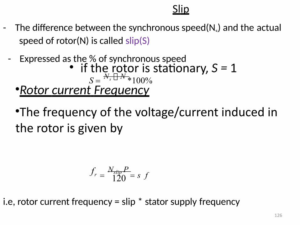
Slip
- The difference between the synchronous speed(Ns) and the actual
speed of rotor(N) is called slip(S)
- Expressed as the % of synchronous speed
S N s N *100%• if the rotor is stationary, S = 1
•Rotor current Frequency
•The frequency of the voltage/current induced in the rotor is given by
Nslip P
s ffr 120
i.e, rotor current frequency = slip * stator supply frequency126
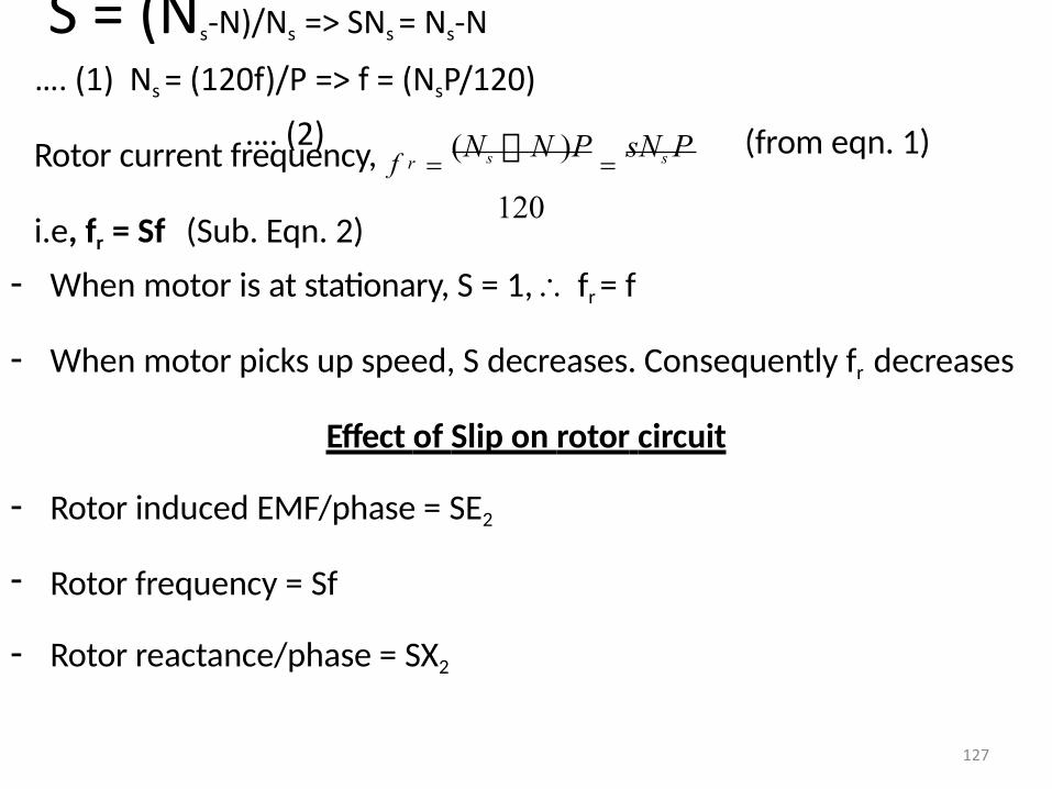
S = (Ns-N)/Ns => SNs = Ns-N
…. (1) Ns = (120f)/P => f = (NsP/120)
…. (2) (from eqn. 1)
(Ns N )P sNs P
120
120
rRotor current frequency, f
i.e, fr = Sf (Sub. Eqn. 2)
- When motor is at stationary, S = 1, fr = f
- When motor picks up speed, S decreases. Consequently fr decreases
Effect of Slip on rotor circuit
- Rotor induced EMF/phase = SE2
- Rotor frequency = Sf
- Rotor reactance/phase = SX2
127
Torque – Slip & Torque – Speed characteristICS
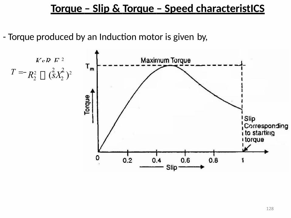
- Torque produced by an Induction motor is given by,
KsR E 2
22R2 (sX )2T 2 2
128
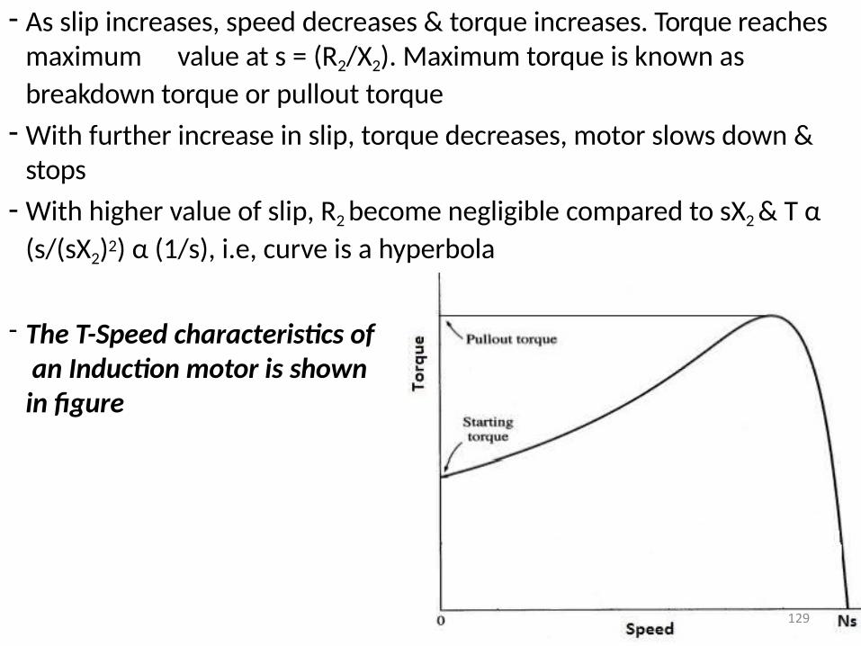
- As slip increases, speed decreases & torque increases. Torque reaches maximum value at s = (R2/X2). Maximum torque is known as
breakdown torque or pullout torque
- With further increase in slip, torque decreases, motor slows down & stops
- With higher value of slip, R2 become negligible compared to sX2 & T α
(s/(sX2)2) α (1/s), i.e, curve is a hyperbola
- The T-Speed characteristics of an Induction motor is shown in figure
129
Torque-Speed curve & operating region
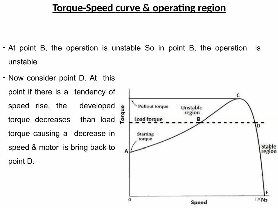
- At point B, the operation is unstable So in point B, the operation is
unstable
- Now consider point D. At this
point if there is a tendency of
speed rise, the developed
torque decreases than load
torque causing a decrease in
speed & motor is bring back to
point D.
130
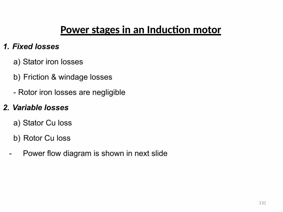
Power stages in an Induction motor
1. Fixed losses
a) Stator iron losses
b) Friction & windage losses
- Rotor iron losses are negligible
2. Variable losses
a) Stator Cu loss
b) Rotor Cu loss
- Power flow diagram is shown in next slide
131
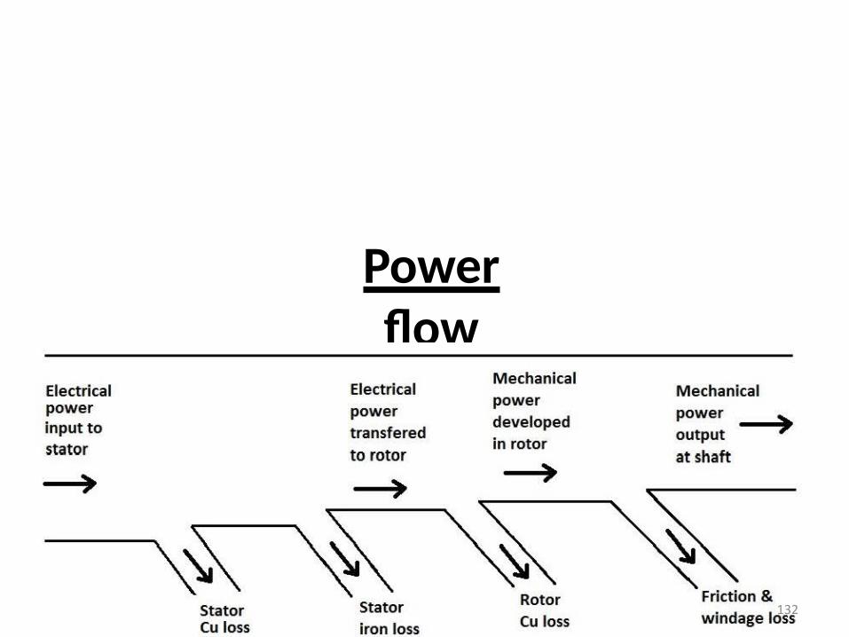
Power flow
diagram
132
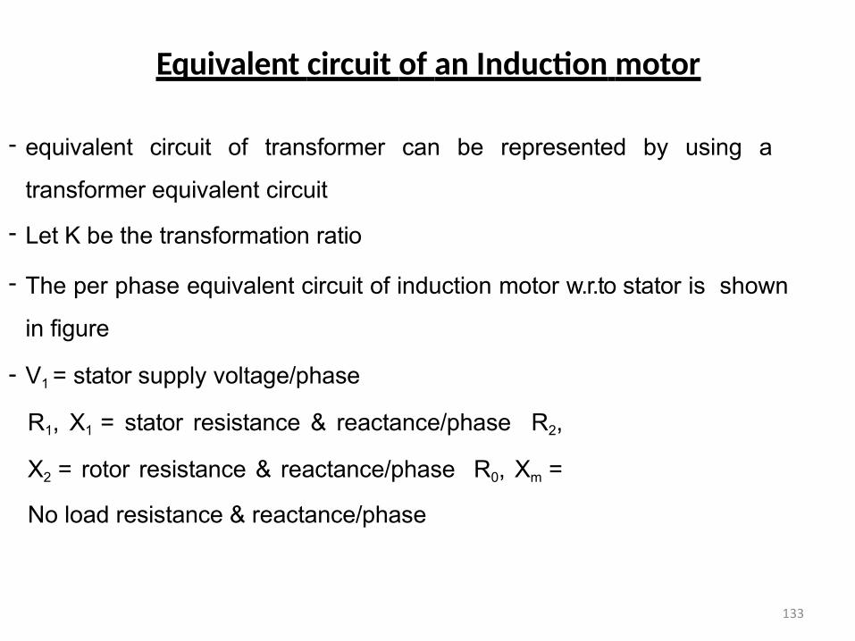
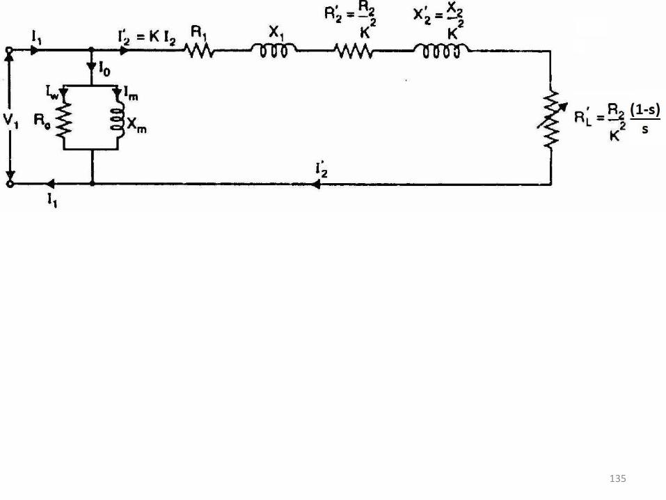
Equivalent circuit of an Induction motor
- equivalent circuit of transformer can be represented by using a
transformer equivalent circuit
- Let K be the transformation ratio
- The per phase equivalent circuit of induction motor w.r.to stator is shown
in figure
- V1 = stator supply voltage/phase
R1, X1 = stator resistance & reactance/phase R2,
X2 = rotor resistance & reactance/phase R0, Xm =
No load resistance & reactance/phase
133
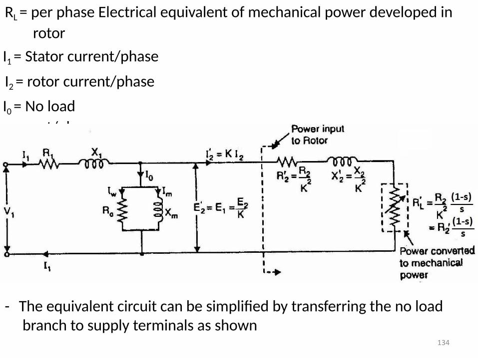
RL = per phase Electrical equivalent of mechanical power developed in
rotor
I1 = Stator current/phase
I2 = rotor current/phase
I0 = No load
current/phase
- The equivalent circuit can be simplified by transferring the no load branch to supply terminals as shown
134
135
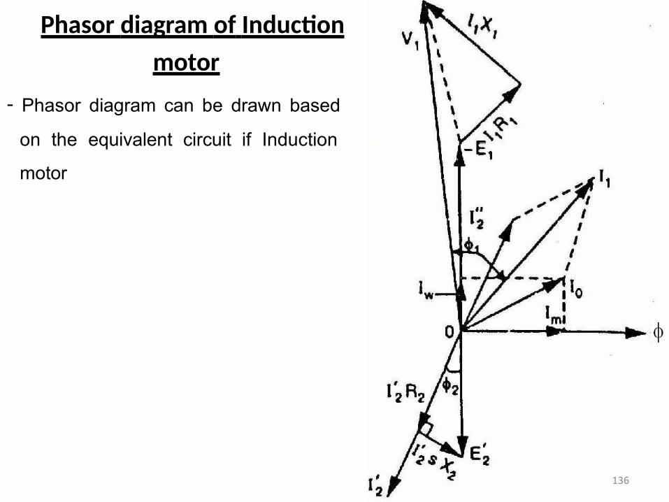
Phasor diagram of Induction
motor
- Phasor diagram can be drawn based
on the equivalent circuit if Induction
motor
136
MODULE V
Tests on Induction motor, Circle diagram, Cogging & Crawling, Double cage Induction motor.
Starting of Induction motors – DOL starter, Autotransformer starter, Star-delta starter, Rotor
resistance starter.
Braking of Induction motor – Plugging, Dynamic braking, Regenerative braking.
Speed control – Stator voltage control, V/F control,Rotor resistance control
Tests on 3 phase Induction Motor
Assume that, the motor stator is star connected
1. Stator resistance measurement
- A DC voltage is applied across any two phase terminals & resistance is measured using
ammeter-voltmeter method. The measured resistance value is given by Voltmeter
reading/Ammeter reading
- Now stator resistance/phase, RDC/ph = Measured resistance value/2
- RAC/ph = RDC/ph*1.25
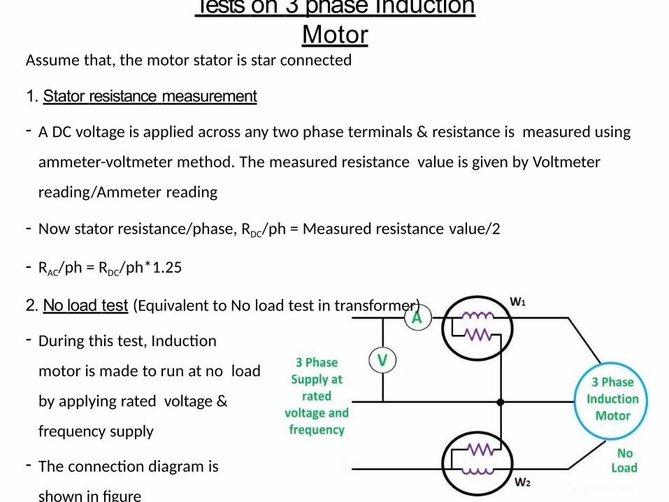
2. No load test (Equivalent to No load test in transformer)
- During this test, Induction
motor is made to run at no load
by applying rated voltage &
frequency supply
- The connection diagram is
shown in figure
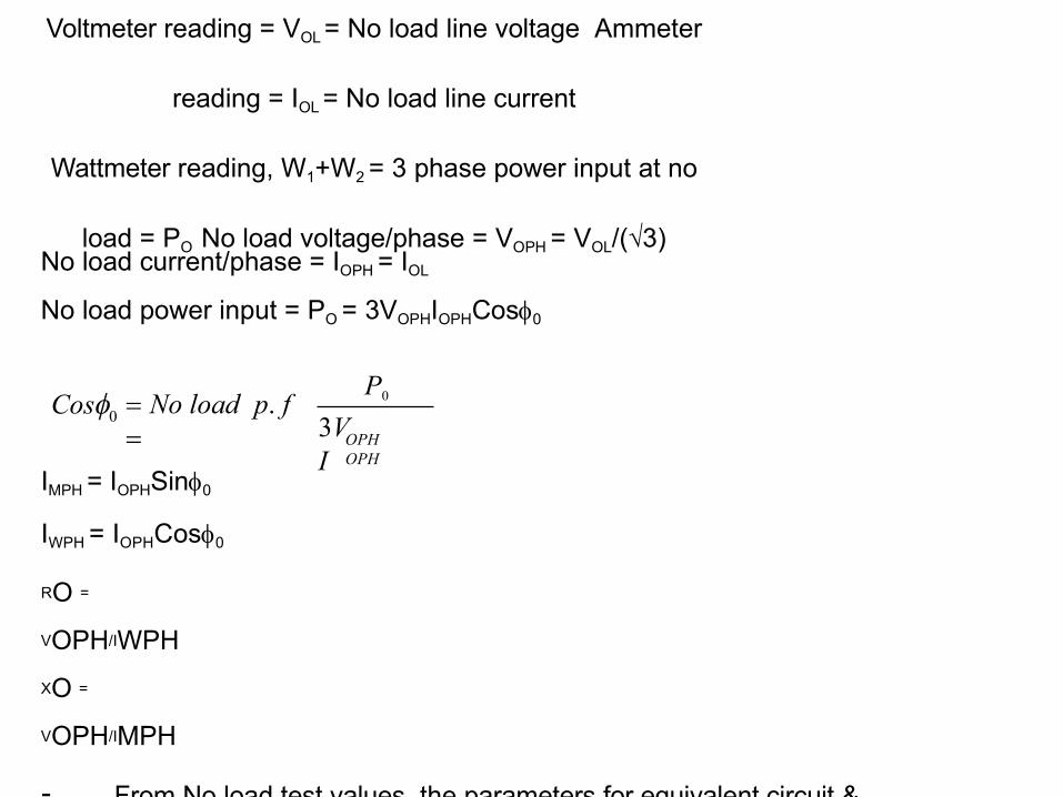
Voltmeter reading = VOL = No load line voltage Ammeter
reading = IOL = No load line current
Wattmeter reading, W1+W2 = 3 phase power input at no
load = PO No load voltage/phase = VOPH = VOL/(√3)No load current/phase = IOPH = IOL
No load power input = PO = 3VOPHIOPHCos0
OPHOPH
3VI
IMPH = IOPHSin0
IWPH = IOPHCos0
RO =
VOPH/IWPH
XO =
VOPH/IMPH
- From No load test values, the parameters for equivalent circuit &
parameters for drawing Circle diagram are obtained
P0 No load p. f
0Cos
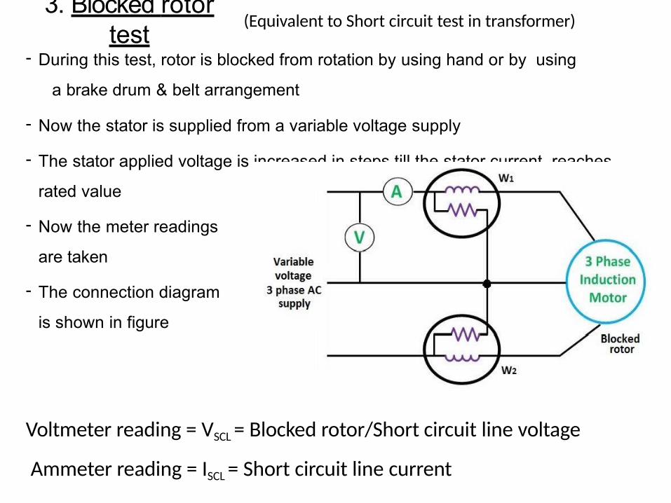
3. Blocked rotor test
(Equivalent to Short circuit test in transformer)
- During this test, rotor is blocked from rotation by using hand or by using
a brake drum & belt arrangement
- Now the stator is supplied from a variable voltage supply
- The stator applied voltage is increased in steps till the stator current reaches
rated value
- Now the meter readings
are taken
- The connection diagram
is shown in figure
Voltmeter reading = VSCL = Blocked rotor/Short circuit line voltage
Ammeter reading = ISCL = Short circuit line current
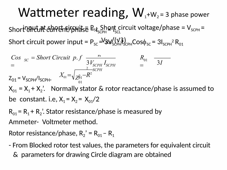
Wattmeter reading, W1+W2 = 3 phase power
input at short circuit = PSC Short circuit voltage/phase = VSCPH =
VSCL/(√3)
Short circuit current/phase = ISCPH = ISCL
Short circuit power input = PSC = 3VSCPHISCPHCosSC = 3ISCPH2 R01
PSC
PSC
Z01 = VSCPH/ISCPH,
SCCos Short Circuit p. f
01SCPH SCPHSCPH
3V I 3I 2
R
0101
Z2 R2X01
X01 = X1 + X2’. Normally stator & rotor reactance/phase is assumed to
be constant. i.e, X1 = X2 = X01/2
R01 = R1 + R2’. Stator resistance/phase is measured by
Ammeter- Voltmeter method.
Rotor resistance/phase, R2’ = R01 – R1
- From Blocked rotor test values, the parameters for equivalent circuit
& parameters for drawing Circle diagram are obtained
Circle diagram
- In a series RL circuit containing a constant reactance (XL) & variable
resistance (R), the locus of current in the circuit is a circle of diameter V/XL
- From equivalent circuit of Induction motor, it is clear that it can be considered as a series RL circuit with constant reactance (X01 =
X1+X2’) & a variable resistance (R01 is constant but load resistance
RL’ = (R2/K2)*((1-s)/s) varies with slip)
- So locus of current I1’ is a circle of radius V/X01
Construction of Circle diagram- Data required for construction of circle diagram is obtained from
No load test, Blocked rotor test & Stator resistance measurement test
- Different steps involved in construction of circle diagram & calculations are given below
- Assume that the stator is star connected
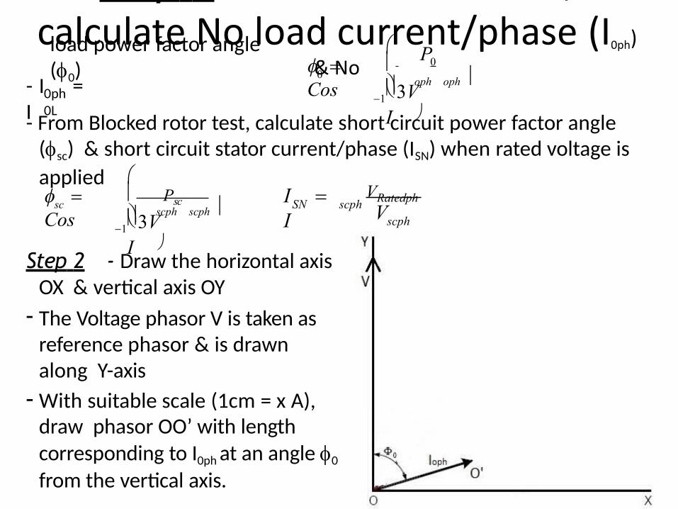
Step 1 - From No load test, calculate No load current/phase (I0ph)
& Noload power factor angle (0)
- I = I
0ph0L
- From Blocked rotor test, calculate short circuit power factor angle (sc) & short circuit stator current/phase (ISN) when rated voltage is
applied
oph oph
P
3VI
0
1
0 Cos
scph scph
scPsc
3VI
1
Cos scph
scphSN VVRatedphI
I
Step 2 - Draw the horizontal axis OX & vertical axis OY
- The Voltage phasor V is taken as reference phasor & is drawn along Y-axis
- With suitable scale (1cm = x A), draw phasor OO’ with length corresponding to I0ph at an angle 0
from the vertical axis.
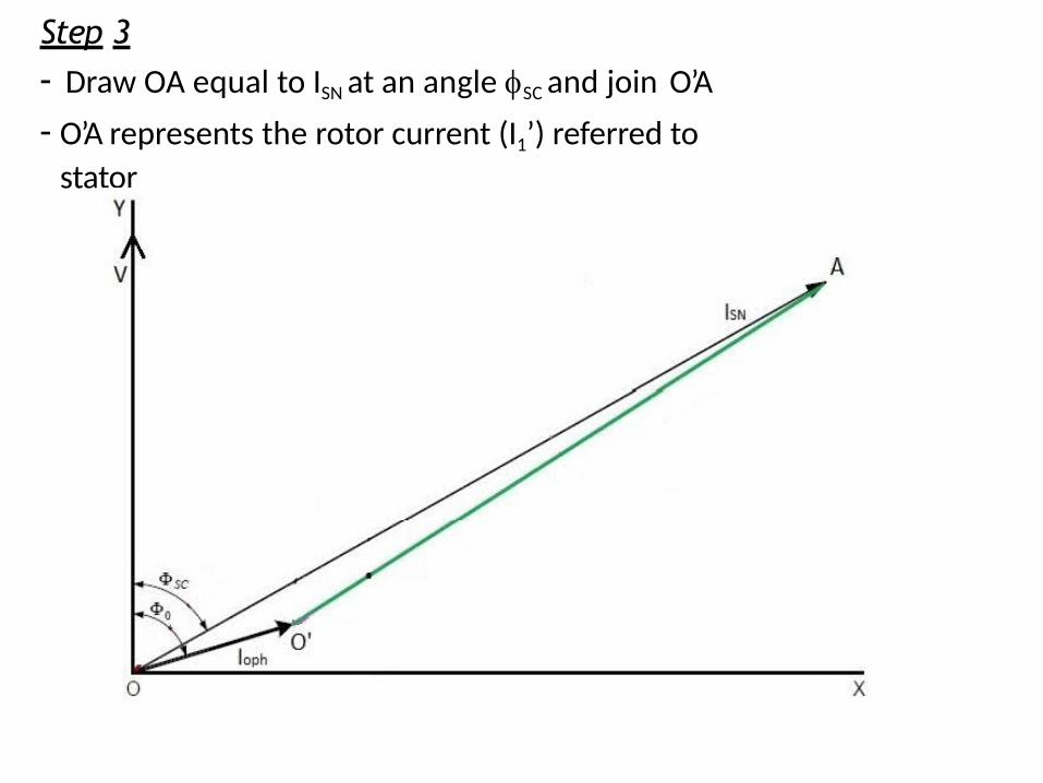
Step 3- Draw OA equal to ISN at an angle SC and join O’A
- O’A represents the rotor current (I1’) referred to
stator
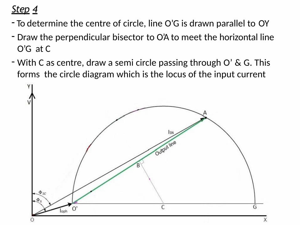
Step 4- To determine the centre of circle, line O’G is drawn parallel to OY
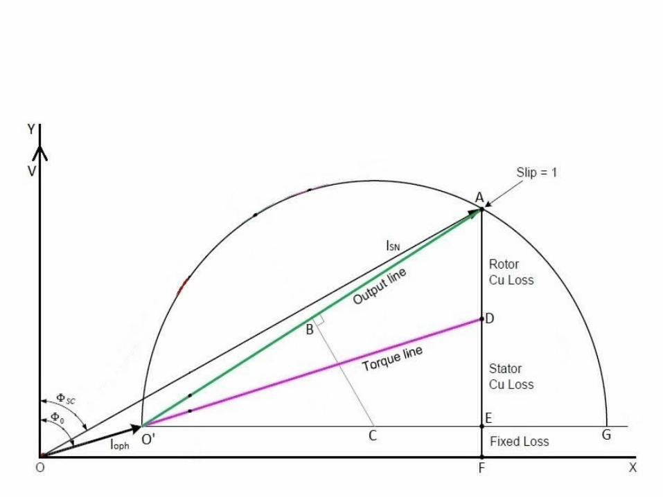
- Draw the perpendicular bisector to O’A to meet the horizontal line O’G at C
- With C as centre, draw a semi circle passing through O’ & G. This forms the circle diagram which is the locus of the input current
Step 5
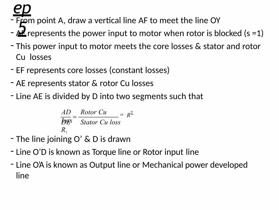
- From point A, draw a vertical line AF to meet the line OY
- AF represents the power input to motor when rotor is blocked (s =1)
- This power input to motor meets the core losses & stator and rotor Cu losses
- EF represents core losses (constant losses)
- AE represents stator & rotor Cu losses
- Line AE is divided by D into two segments such that
R 'AD Rotor Cu loss
2
DE Stator Cu lossR1
- The line joining O’ & D is drawn
- Line O’D is known as Torque line or Rotor input line
- Line O’A is known as Output line or Mechanical power developed line
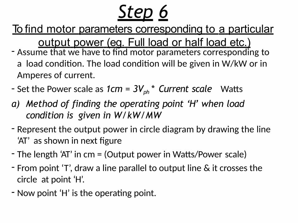
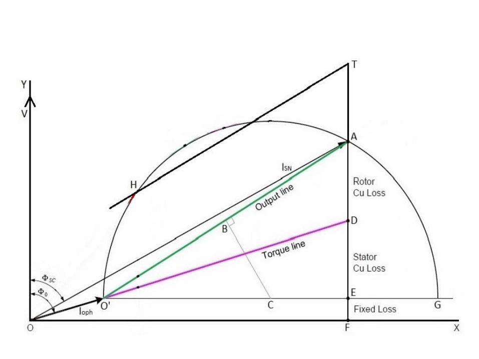
Step 6To find motor parameters corresponding to a particular
output power (eg. Full load or half load etc.)- Assume that we have to find motor parameters corresponding to
a load condition. The load condition will be given in W/kW or in Amperes of current.
- Set the Power scale as 1cm = 3Vph * Current scale Watts
a) Method of finding the operating point ‘H’ when load condition is given in W/kW/MW
- Represent the output power in circle diagram by drawing the line ‘AT’ as shown in next figure
- The length ‘AT’ in cm = (Output power in Watts/Power scale)
- From point ‘T’, draw a line parallel to output line & it crosses the circle at point ‘H’.
- Now point ‘H’ is the operating point.
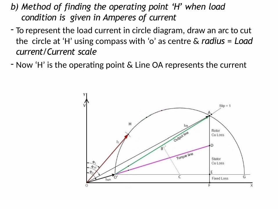
b) Method of finding the operating point ‘H’ when load condition is given in Amperes of current
- To represent the load current in circle diagram, draw an arc to cut the circle at ‘H’ using compass with ‘o’ as centre & radius = Load current/Current scale
- Now ‘H’ is the operating point & Line OA represents the current
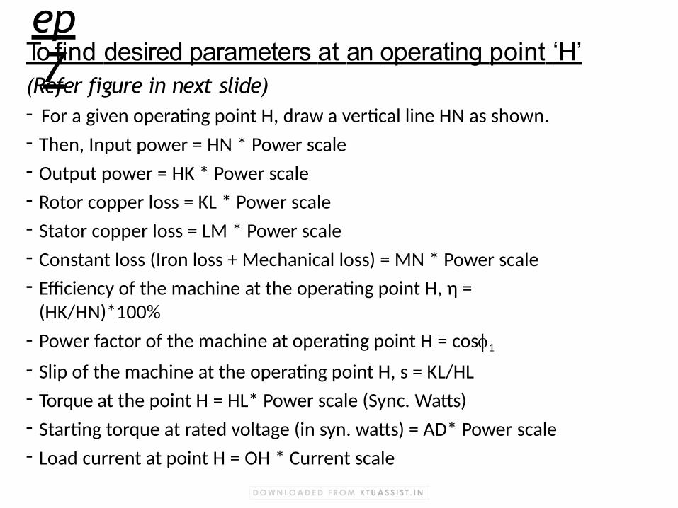
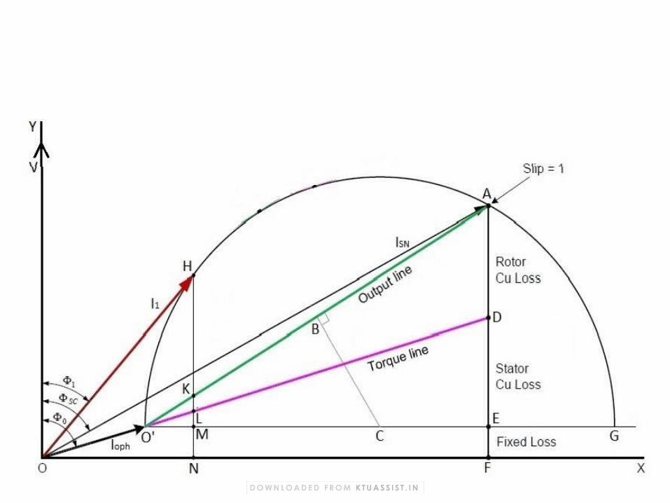
Step 7To find desired parameters at an operating point ‘H’
(Refer figure in next slide)- For a given operating point H, draw a vertical line HN as shown.
- Then, Input power = HN * Power scale
- Output power = HK * Power scale
- Rotor copper loss = KL * Power scale
- Stator copper loss = LM * Power scale
- Constant loss (Iron loss + Mechanical loss) = MN * Power scale
- Efficiency of the machine at the operating point H, η = (HK/HN)*100%
- Power factor of the machine at operating point H = cos1
- Slip of the machine at the operating point H, s = KL/HL
- Torque at the point H = HL* Power scale (Sync. Watts)
- Starting torque at rated voltage (in syn. watts) = AD* Power scale
- Load current at point H = OH * Current scale
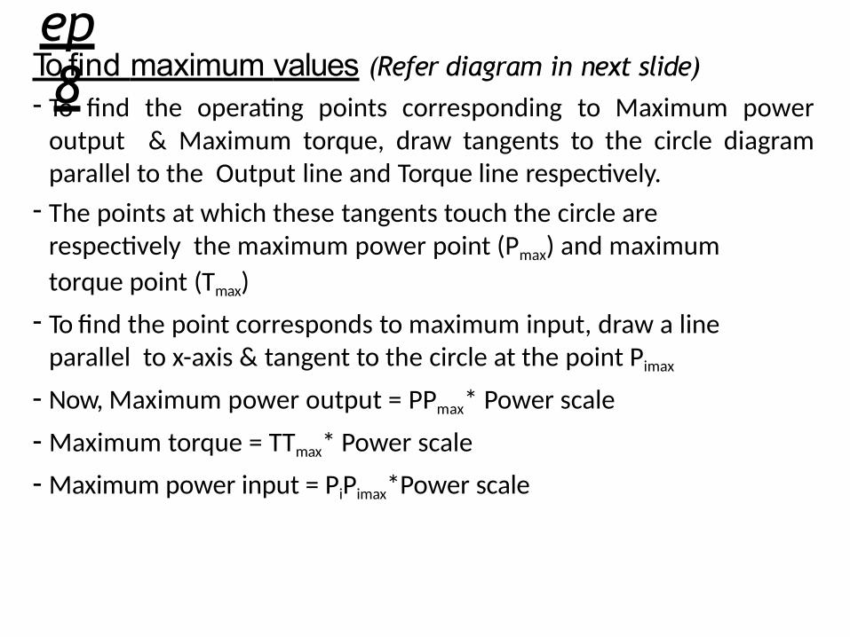
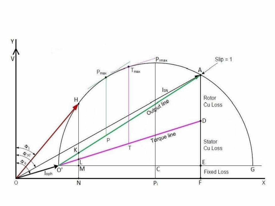
Step 8To find maximum values (Refer diagram in next slide)
- To find the operating points corresponding to Maximum power output & Maximum torque, draw tangents to the circle diagram parallel to the Output line and Torque line respectively.
- The points at which these tangents touch the circle are respectively the maximum power point (Pmax) and maximum
torque point (Tmax)
- To find the point corresponds to maximum input, draw a line parallel to x-axis & tangent to the circle at the point Pimax
- Now, Maximum power output = PPmax* Power scale
- Maximum torque = TTmax* Power scale
- Maximum power input = PiPimax*Power scale
Cogging- At certain times, even when full voltage is applied to stator
winding, the Squirrel Cage Induction motors refuses to start & pick up speed
- This phenomenon is called cogging or teeth locking- Cogging is due to magnetic locking between stator & rotor teeth- Cogging occur when number of stator slots (S1) is an integral
multiple of number of rotor slots (S2)
- This mainly occur in squirrel cage induction motor because in slip ring induction motor, starting torque is high
- Cogging can be avoided by making S1 S2 & also by skewing the
rotor
Crawling- 3 phase induction motors, especially cage motors exhibit a tendency
to run stably at a sub-synchronous speed (1/7th of synchronous speed) & is unable to pickup its normal speed
- This unusual phenomenon is called crawling- If voltage applied to stator winding contain harmonics, the airgap
flux won’t be sinusoidal
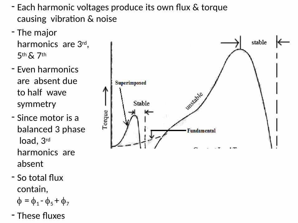
- Each harmonic voltages produce its own flux & torque causing vibration & noise
- The major harmonics are 3rd, 5th & 7th
- Even harmonics are absent due to half wave symmetry
- Since motor is a balanced 3 phase load, 3rd
harmonics are absent
- So total flux contain, = 1 - 5 + 7
- These fluxes produce torques in motor
- 5th harmonic produce a braking torque
- 1st & 7th produce motoring torque
- Torque produced by 1st & 7th superimposes to get net Torque – speed characteristics of motor as shown in figure
- The load torque line intercepts Torque – Speed curve at points M & N
- At ‘M’ motor is able to provide stable operation at speed NS/7
Methods to avoid crawling
- Number of stator slots, S1 Number of rotor slots,S2
- Difference between S1 & S2 should be P, 2P or 5P
- Difference between S1 & S2 should not be 1, 2, (P1) or (P2) to avoid noise & vibration
- Reduce 5th & 7th harmonics by short pitching the windings
High torque Cage motors- SCIM has high efficiency, low cost, low maintenance etc.
- But it is having low starting torque, low p.f & high starting current- A SRIM is having high starting torque, low starting current & high
p.f due to high rotor resistance value- So our requirement is high rotor resistance during starting to get
more torque & low rotor resistance under normal operation- It can be achieved by 2 methods
1. Double cage Induction motor
2. Deep bar Induction motor
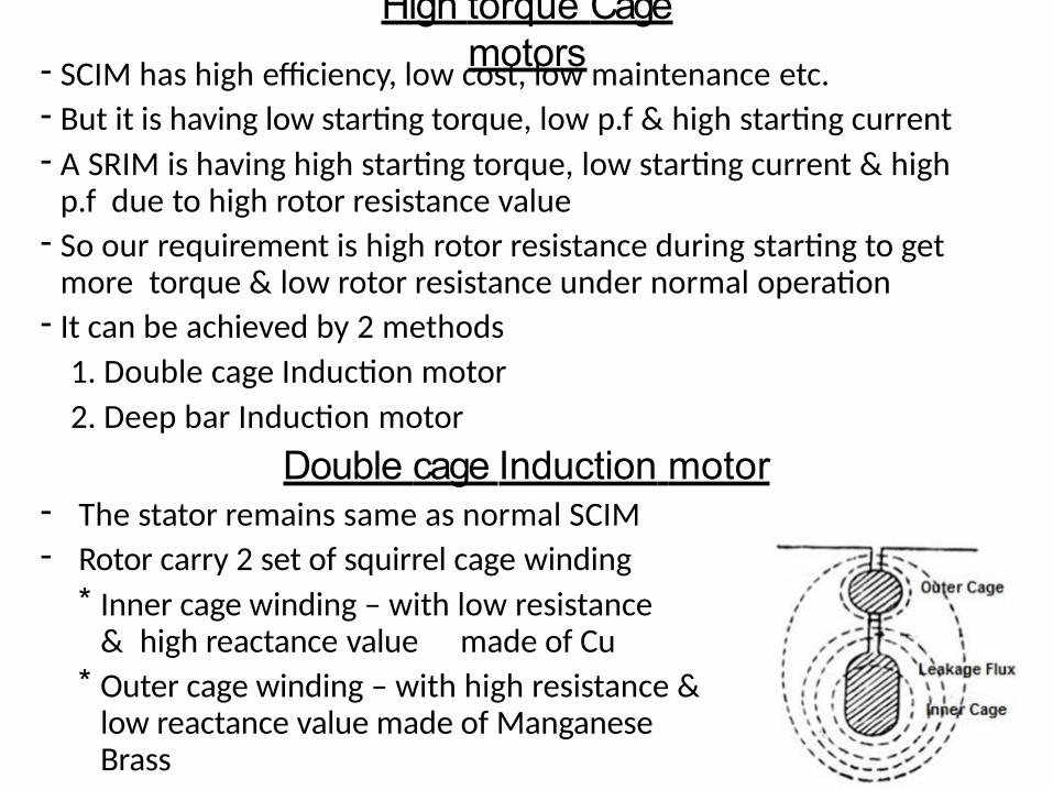
Double cage Induction motor- The stator remains same as normal SCIM- Rotor carry 2 set of squirrel cage winding
* Inner cage winding – with low resistance & high reactance value made of Cu
* Outer cage winding – with high resistance & low reactance value made of Manganese Brass
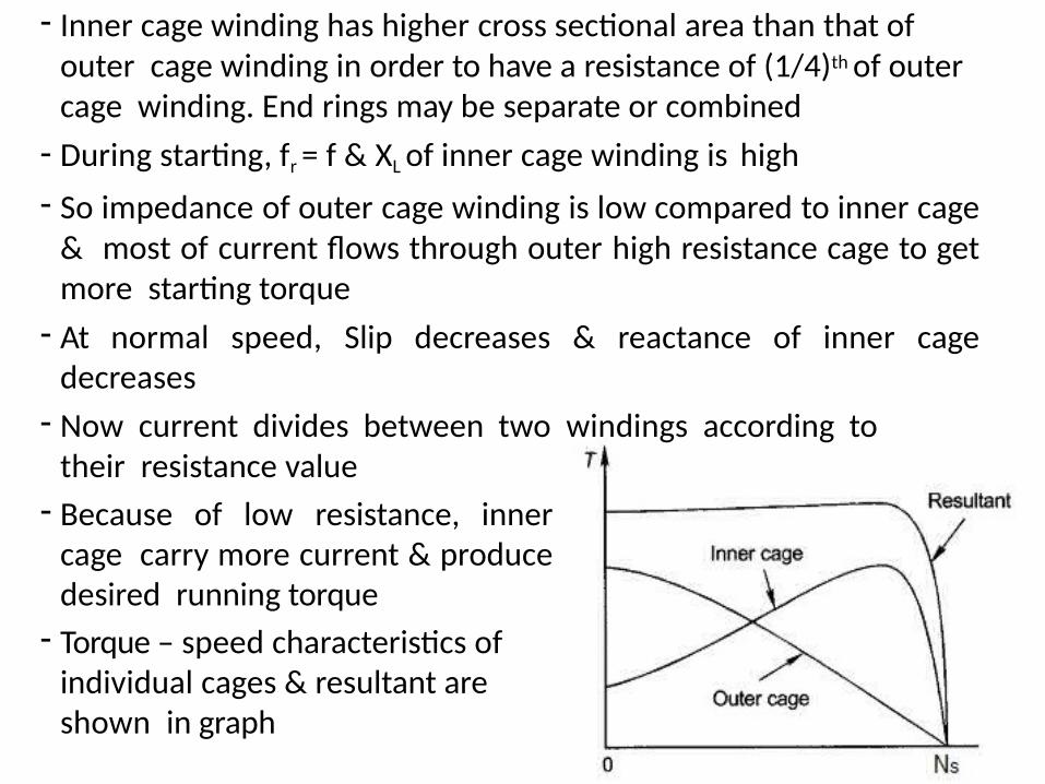
- Inner cage winding has higher cross sectional area than that of outer cage winding in order to have a resistance of (1/4)th of outer cage winding. End rings may be separate or combined
- During starting, fr = f & XL of inner cage winding is high
- So impedance of outer cage winding is low compared to inner cage & most of current flows through outer high resistance cage to get more starting torque
- At normal speed, Slip decreases & reactance of inner cage decreases
- Now current divides between two windings according to their resistance value
- Because of low resistance, inner cage carry more current & produce desired running torque
- Torque – speed characteristics of individual cages & resultant are shown in graph
Need of starter
- In the case of an Induction motor at starting, when motor is standstill, the squirrel cage rotor is like a short circuited secondary of a transformer
- Therefore if full supply voltage is applied during stating, current in rotor circuit will be very high & consequently stator also draw a high current from supply
- Magnitude of this current depends on electrical design of motor & is usually 5 to 7 times rated full load current
- To limit the current within safe value starter is used
Functions of starter
- Limit the starting current within safe limit
- Provide protection against overload & under voltage
- In SRIM, starter helps to improve starting torque
Starting of Squirrel cage Induction motor
- Different type of starters used in SCIM are
1. DOL (Direct On Line) starter or Full voltage starter- This is the most economical method of starting
- DOL starter is used based on following factors
* Power rating & design of motor
* Type of application
* Location of motor in distributed system
* Capacity of power system
- This method involves direct switching of poly phase SCIM to supply as shown in figure
- It consist of start & stop button, a contactor, overload & under voltage protection devices
- Start button is a normally open switch & Stop button is normally closed switch
- For starting the motor, main switch is closed
- Now start button is pressed & operating coil of contactor gets energized
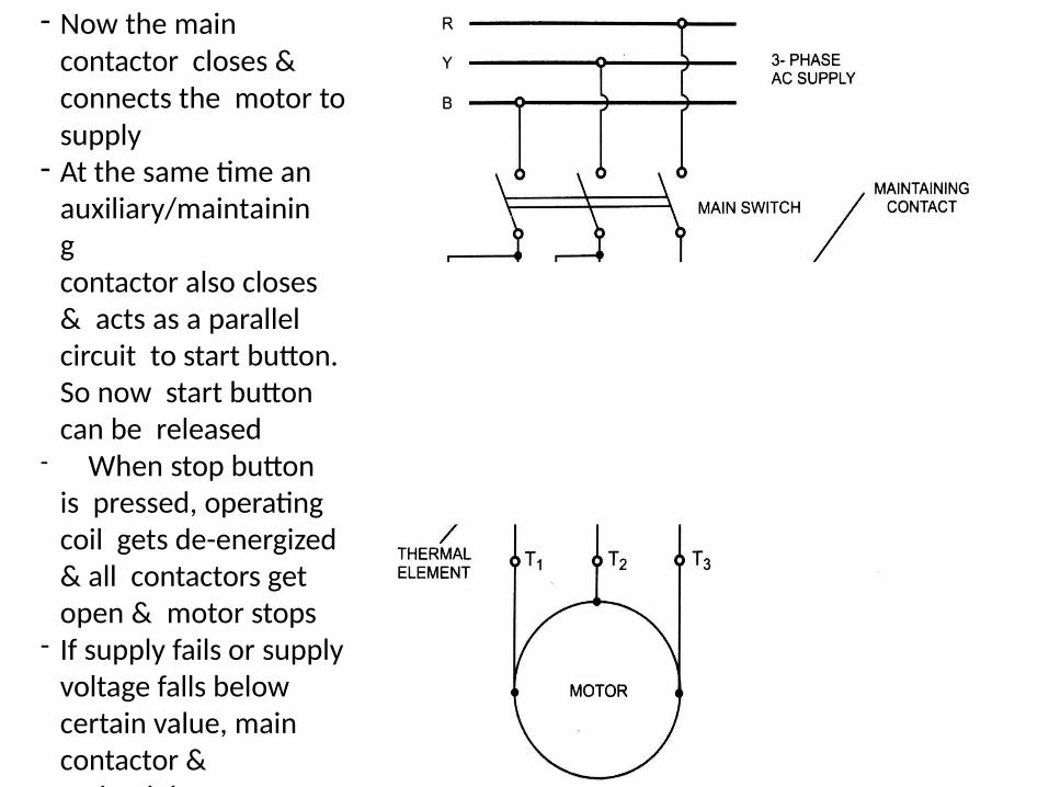
- Now the main contactor closes & connects the motor to supply
- At the same time an auxiliary/maintainingcontactor also closes & acts as a parallel circuit to start button. So now start button can be released
- When stop button is pressed, operating coil gets de-energized & all contactors get open & motor stops
- If supply fails or supply voltage falls below certain value, main contactor & maintaining contactor gets open
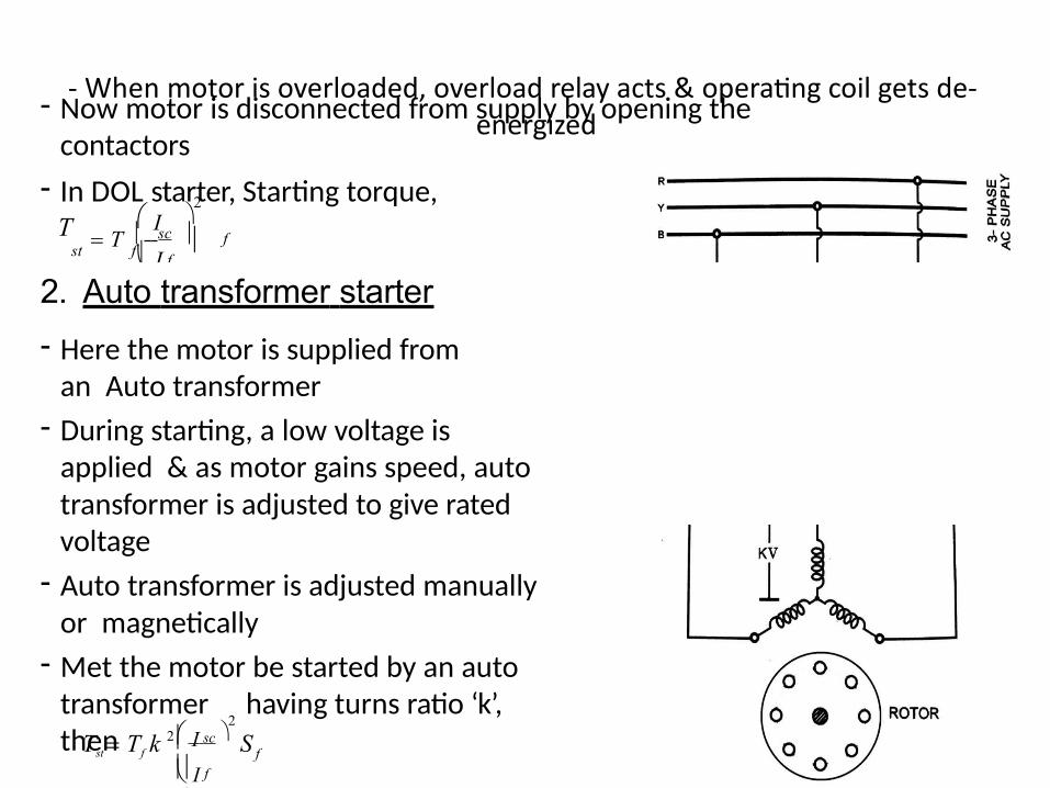
- When motor is overloaded, overload relay acts & operating coil gets de- energized
- Now motor is disconnected from supply by opening the contactors
- In DOL starter, Starting torque,
ff
T
2
st f I
I T sc
S2. Auto transformer starter
- Here the motor is supplied from an Auto transformer
- During starting, a low voltage is applied & as motor gains speed, autotransformer is adjusted to give rated voltage
- Auto transformer is adjusted manually or magnetically
- Met the motor be started by an auto transformer having turns ratio ‘k’, then f
f
sc S2 2
I
ITst Tf k
- i.e Starting torque = (1/k2) *
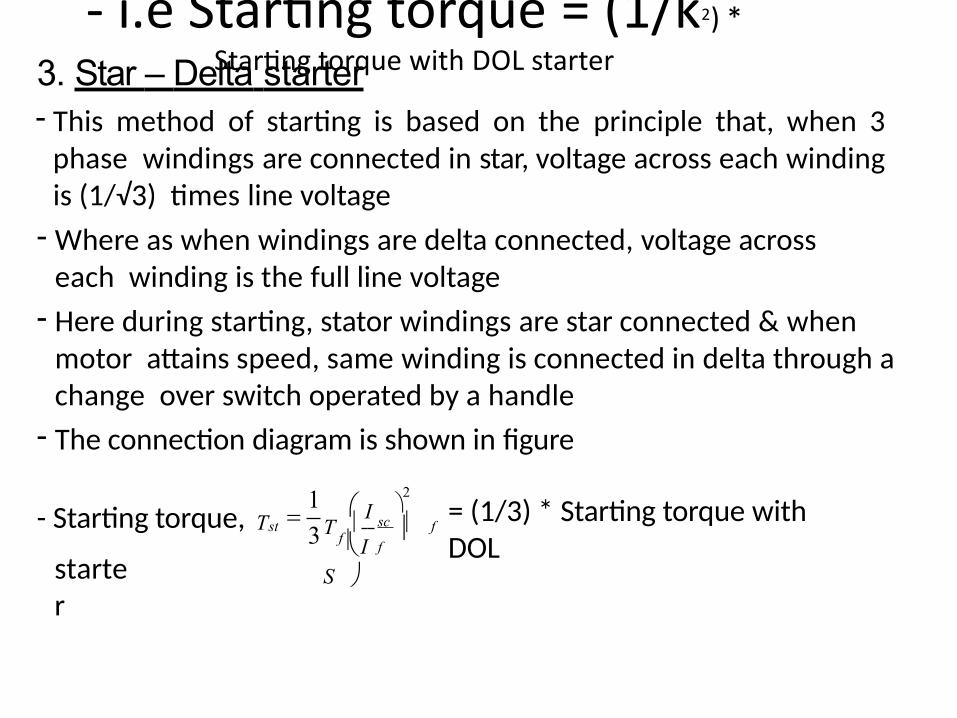
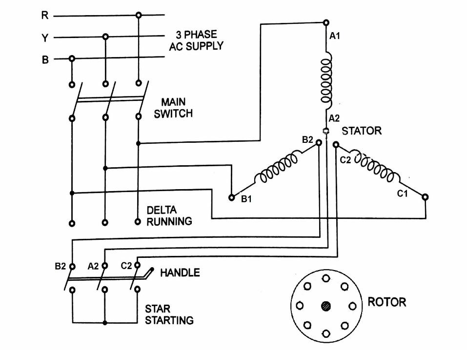
Starting torque with DOL starter3. Star – Delta starter- This method of starting is based on the principle that, when 3
phase windings are connected in star, voltage across each winding is (1/√3) times line voltage
- Where as when windings are delta connected, voltage across each winding is the full line voltage
- Here during starting, stator windings are star connected & when motor attains speed, same winding is connected in delta through a change over switch operated by a handle
- The connection diagram is shown in figure
= (1/3) * Starting torque with DOL
starter
f
f
st- Starting torque, T1
3
2
f IT sc
S
I
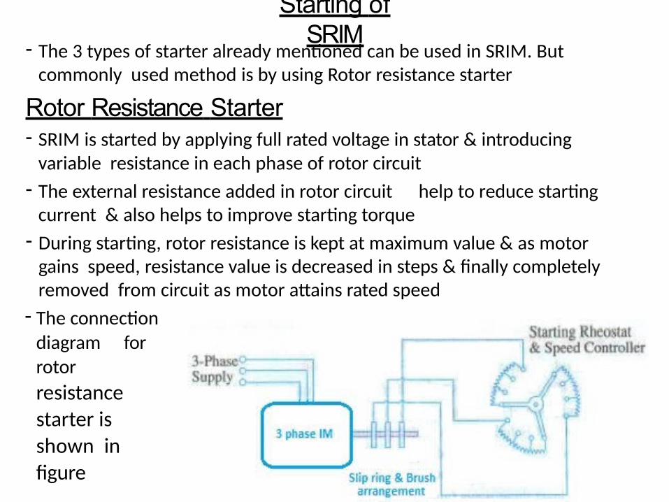
Starting of SRIM
- The 3 types of starter already mentioned can be used in SRIM. But commonly used method is by using Rotor resistance starter
Rotor Resistance Starter- SRIM is started by applying full rated voltage in stator & introducing
variable resistance in each phase of rotor circuit
- The external resistance added in rotor circuit help to reduce starting current & also helps to improve starting torque
- During starting, rotor resistance is kept at maximum value & as motor gains speed, resistance value is decreased in steps & finally completely removed from circuit as motor attains rated speed
- The connection diagram for rotor
resistance starter is shown in figure
Braking of Induction motor
- The simplest method of stopping of an Induction motor is to disconnect the motor from supply mains
- Now motor automatically stops due to combined effect of rotor & load (Kinetic energy in rotating parts gets dissipated as heat due to friction)
- When rapid stopping required, mechanical or electrical braking is employed
- There are mainly three methods of Electrical braking
1. Plugging or Counter current braking- Plugging can be achieved in an Induction motor by interchanging
connections of any two phases of stator w.r.to supply terminals
- This causes a reversal of the direction of rotational magnetic field & direction of torque produced by the motor
- The torque produced by motor under braking condition acts as a braking torque & speed of motor decreases
- During braking, motor runs in the opposite direction of rotational magnetic field & a large voltage induces in rotor windings. So rotor windings should be provided with additional insulation to withstand this high voltage
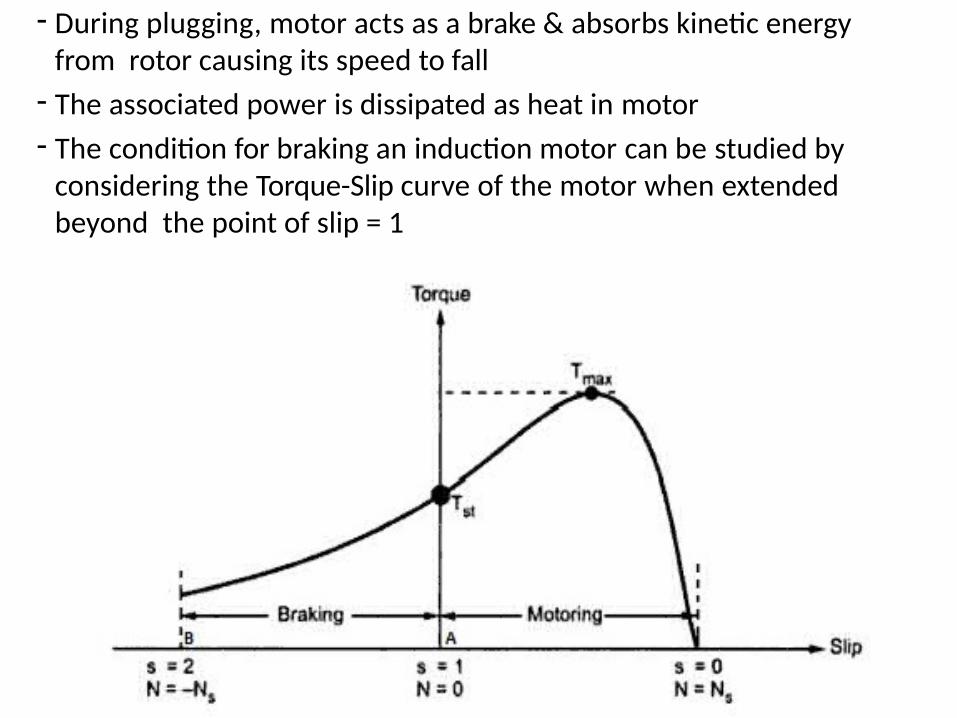
- During plugging, motor acts as a brake & absorbs kinetic energy from rotor causing its speed to fall
- The associated power is dissipated as heat in motor
- The condition for braking an induction motor can be studied by considering the Torque-Slip curve of the motor when extended beyond the point of slip = 1
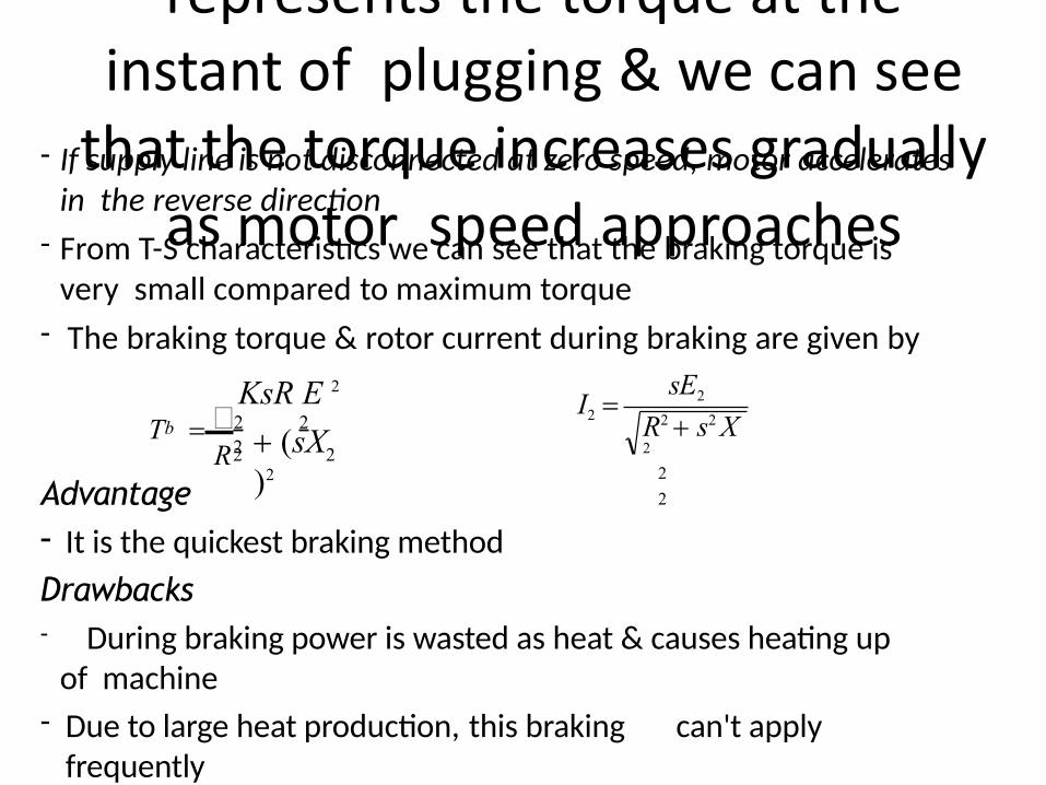
- The y-coordinate at point B represents the torque at the
instant of plugging & we can see that the torque increases gradually
as motor speed approaches standstill
- If supply line is not disconnected at zero speed, motor accelerates in the reverse direction
- From T-S characteristics we can see that the braking torque is very small compared to maximum torque
- The braking torque & rotor current during braking are given by
22R2
KsR E 2
b (sX)2
T 2 2
sE2
R2 s2 X 2
2
2
I2
Advantage- It is the quickest braking method
Drawbacks- During braking power is wasted as heat & causes heating up
of machine
- Due to large heat production, this braking can't apply frequently
2. Dynamic or Rheostatic braking- Here during braking the stator windings are disconnected from
AC supply & is connected to a DC source- Now a stationary DC field is produced in stator & act as field
excitation of a DC motor- The rotor windings of Induction motor acts as armature winding- In SRIM, external resistances can be inserted into rotor circuit
- When stator windings are disconnected from AC supply & excited with DC, the magnetic field produced will be stationary & rotor will be rotating
- Now current induces in rotor conductors & torque is produced by motoring action
- The direction of torque produced is in opposite direction to that corresponding to normal motoring operation
- This produces a braking torque & motor speed reduces
- The magnitude of braking torque developed depends upon the DC excitation, rotor resistance & speed of motor
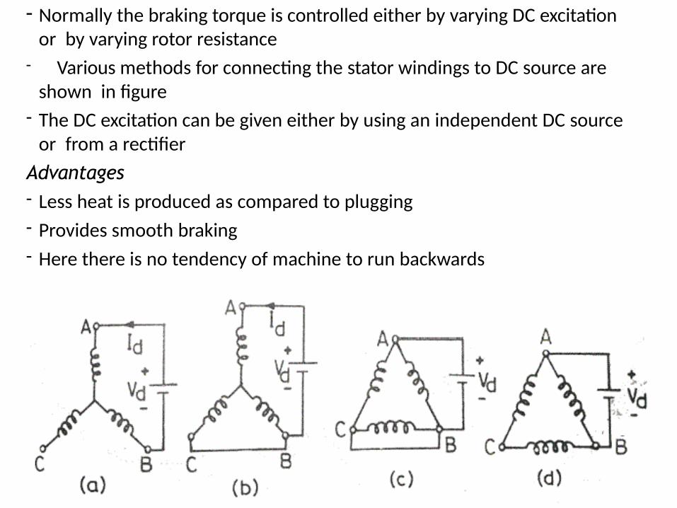
- Normally the braking torque is controlled either by varying DC excitation or by varying rotor resistance
- Various methods for connecting the stator windings to DC source are shown in figure
- The DC excitation can be given either by using an independent DC source or from a rectifier
Advantages- Less heat is produced as compared to plugging
- Provides smooth braking
- Here there is no tendency of machine to run backwards
3. Regenerative Braking- During regenerative braking, Induction motor works as a generator
& electrical power generated is fed back to the supply
- This generator action produces the required braking torque
- When speed of an Induction motor increases above synchronous speed, it acts as an Induction generator
- The Induction motor can be made to operate at speed above synchronous speed by any of the following method
* Switching over to a low frequency supply in frequency controlled induction motor drives
* Switching over to a large number of poles operation from a smaller one in multi speed squirrel cage motors
- During braking, slip & torque become negative & machine acts as a generator receiving mechanical energy & giving back electrical energy to supply
- The torque – speed characteristics of an Induction motor under regenerative braking operation is shown in figure
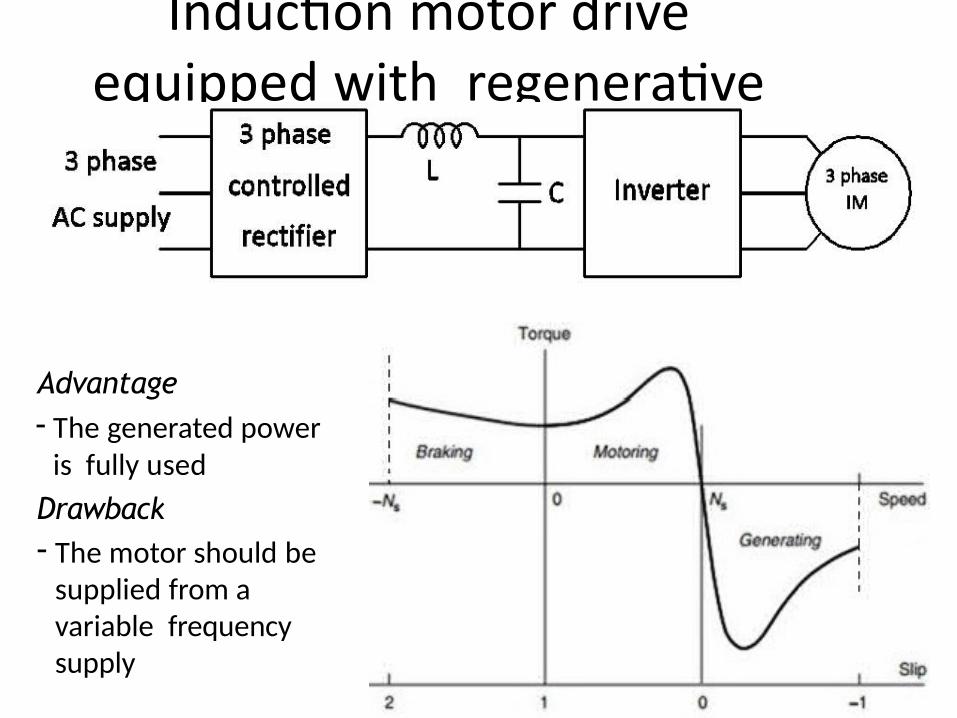
- The block diagram of an Induction motor drive
equipped with regenerative braking is shown in figure
Advantage- The generated power
is fully used
Drawback- The motor should be
supplied from a variable frequency supply
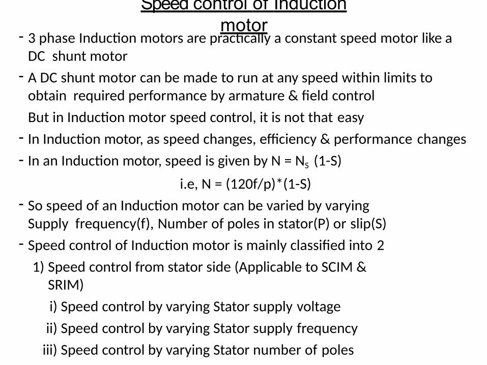
Speed control of Induction motor
- 3 phase Induction motors are practically a constant speed motor like a DC shunt motor
- A DC shunt motor can be made to run at any speed within limits to obtain required performance by armature & field control
But in Induction motor speed control, it is not that easy
- In Induction motor, as speed changes, efficiency & performance changes
- In an Induction motor, speed is given by N = NS (1-S)
i.e, N = (120f/p)*(1-S)
- So speed of an Induction motor can be varied by varying Supply frequency(f), Number of poles in stator(P) or slip(S)
- Speed control of Induction motor is mainly classified into 2
1) Speed control from stator side (Applicable to SCIM & SRIM)
i) Speed control by varying Stator supply voltage
ii) Speed control by varying Stator supply frequency
iii) Speed control by varying Stator number of poles
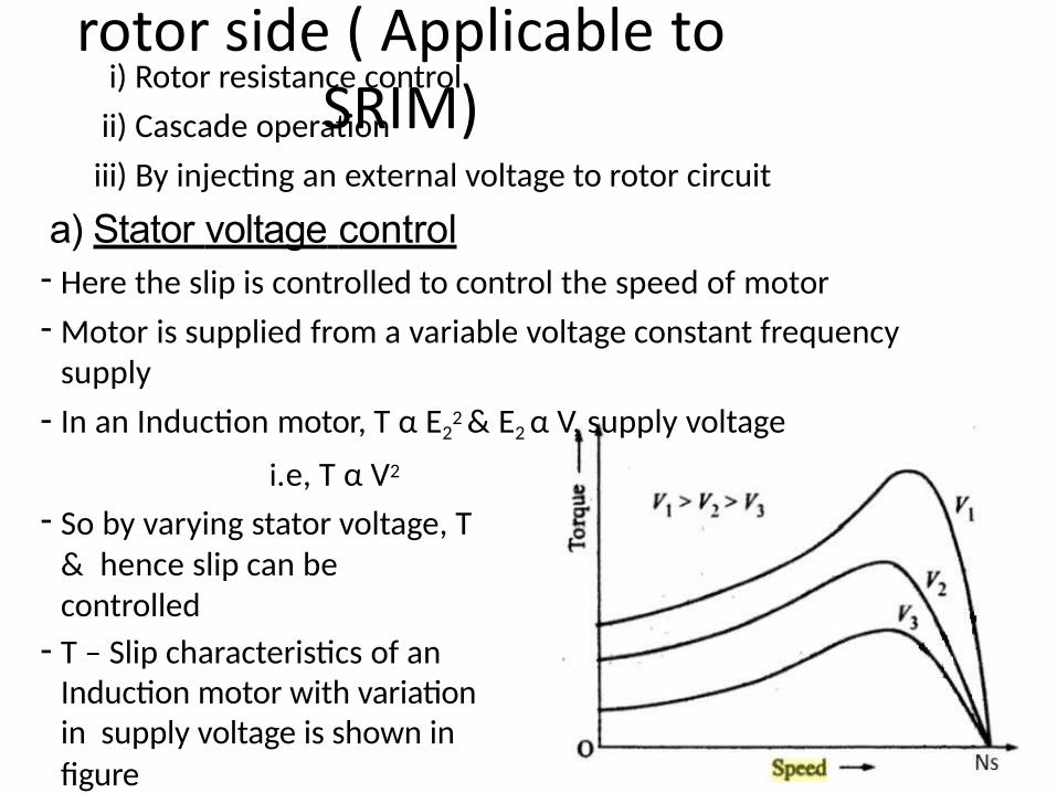
2) Speed control from rotor side ( Applicable to
SRIM)i) Rotor resistance control
ii) Cascade operation
iii) By injecting an external voltage to rotor circuit
a) Stator voltage control- Here the slip is controlled to control the speed of motor
- Motor is supplied from a variable voltage constant frequency supply
- In an Induction motor, T α E22 & E2 α V, supply voltage
i.e, T α V2
- So by varying stator voltage, T & hence slip can be controlled
- T – Slip characteristics of an Induction motor with variation in supply voltage is shown infigure
- Applied voltage can be varied by using a 3 phase autotransformer or
tap changing transformerAdvantage - Simple, low cost
Drawbacks
- Voltage can’t be increased above rated value. So speed control below rated speed is only possible
- A large change in voltage is required to get a small change in speed
- The torque developed changes with change in supply voltage
b) V/f control- Speed of Induction motor can be varied by varying supply
frequency
- But from EMF equation of Induction motor, α (1/f)
- So when we decrease frequency to reduce speed, flux increases & causes saturation of core. The core losses also increases
- If frequency is increased to increase speed, flux reduces & torque produced by motor reduces
- So we have to maintain flux in the machine constant
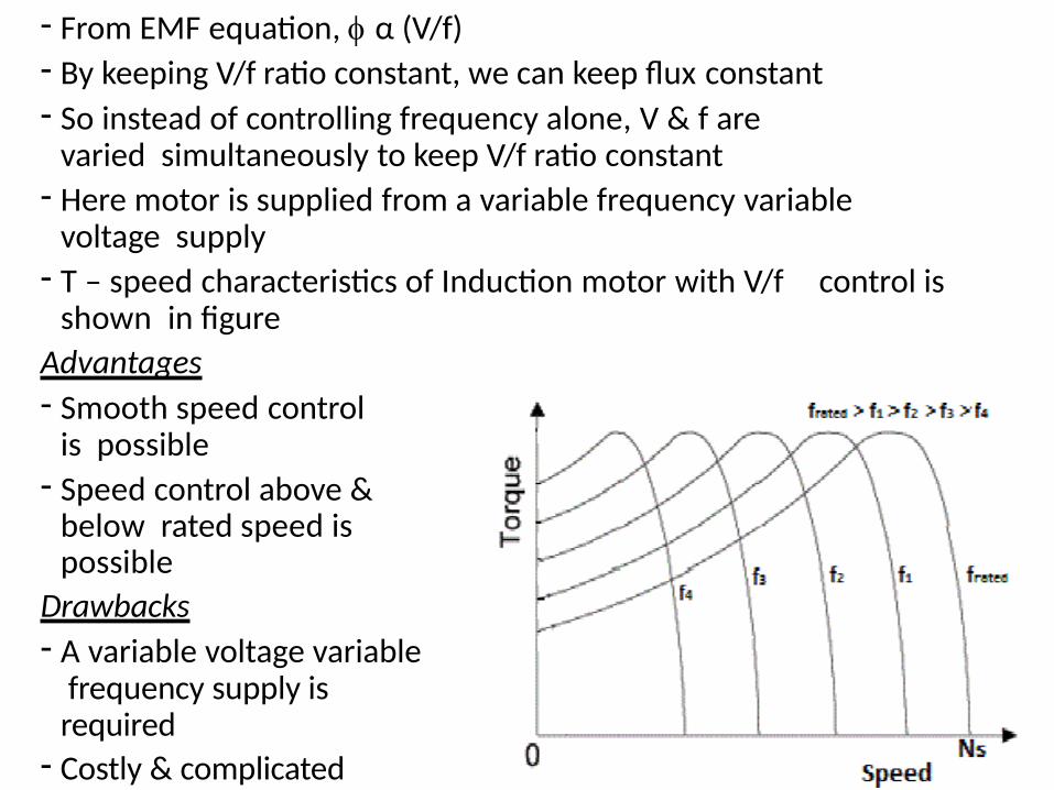
- From EMF equation, α (V/f)- By keeping V/f ratio constant, we can keep flux constant- So instead of controlling frequency alone, V & f are
varied simultaneously to keep V/f ratio constant- Here motor is supplied from a variable frequency variable
voltage supply- T – speed characteristics of Induction motor with V/f control is
shown in figure
Advantages
- Smooth speed control is possible
- Speed control above & below rated speed is possible
Drawbacks
- A variable voltage variable frequency supply is required
- Costly & complicated
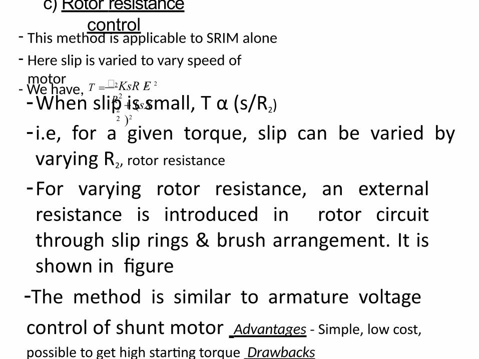
c) Rotor resistance control
- This method is applicable to SRIM alone
- Here slip is varied to vary speed of motor
22
KsR E 2
(sX)2
- We have, T 2 2
R2-When slip is small, T α (s/R2)
- i.e, for a given torque, slip can be varied by varying R2, rotor resistance
-For varying rotor resistance, an external resistance is introduced in rotor circuit through slip rings & brush arrangement. It is shown in figure
-The method is similar to armature voltage
control of shunt motor Advantages - Simple, low cost,
possible to get high starting torque Drawbacks
- With increase in rotor resistance, loss increases & efficiency decreases
- Here speed depends on R2 & load
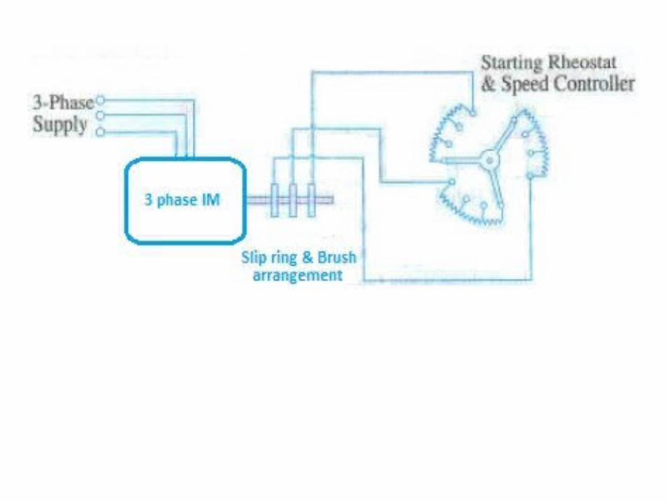
MODULE - VI
• Induction Generator – Principle, Grid connected &
Self excited operation, Comparison of Induction
generator & Synchronous generator,
• Synchronous Induction motor – Principle,
• Single phase Induction motor – Double field
revolving theory, Equivalent circuit, Torque – Slip
Curve, Types of Single phase Induction motor –
Split phase, Capacitor start, Capacitor start & run
type, Shaded pole Induction motor – Principle,
applications
Induction Generator
- An Induction Generator is a poly phase Induction machine working as a
generator
- When an Induction machine is connected to 3 phase AC supply, it will work as
a motor drawing power from supply
- The motor speed will be less than synchronous speed & slip is positive
- If the induction motor is coupled to a prime mover (whose speed can be
controlled), the speed of Induction motor can be increased above
synchronous speed
- Now slip is negative & direction of current, power & torque reverses
- i.e, Machine works as a generator & produces electrical energy
- The produced electrical energy is fed back to supply
- The Torque – Speed characteristics of Induction generator is shown in figure
- The Induction generator takes the required reactive power from supply to produce
the magnetic field in machine. So it is not a self excited machine
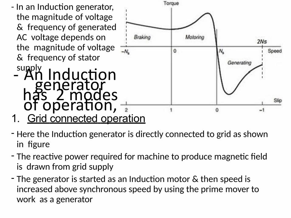
- In an Induction generator, the magnitude of voltage & frequency of generated AC voltage depends on the magnitude of voltage & frequency of stator supply- An Induction
generator has 2 modes of operation,
1. Grid connected operation- Here the Induction generator is directly connected to grid as shown
in figure- The reactive power required for machine to produce magnetic field
is drawn from grid supply- The generator is started as an Induction motor & then speed is
increased above synchronous speed by using the prime mover to work as a generator
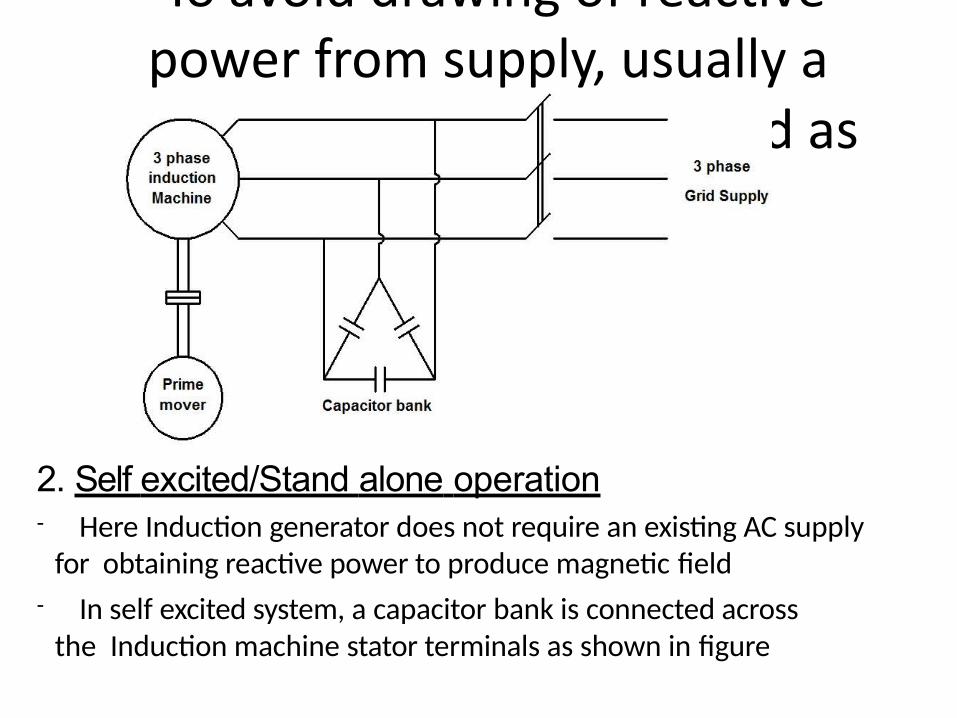
- To avoid drawing of reactive power from supply, usually a
capacitor bank is connected as shown in figure
2. Self excited/Stand alone operation- Here Induction generator does not require an existing AC supply
for obtaining reactive power to produce magnetic field
- In self excited system, a capacitor bank is connected across the Induction machine stator terminals as shown in figure
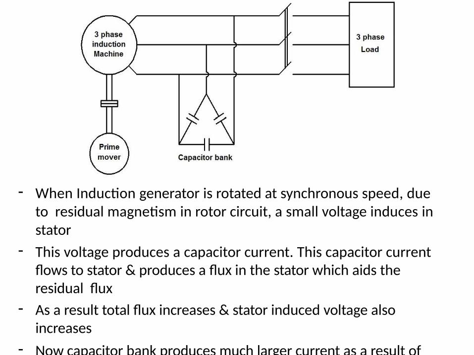
- When Induction generator is rotated at synchronous speed, due to residual magnetism in rotor circuit, a small voltage induces in stator
- This voltage produces a capacitor current. This capacitor current flows to stator & produces a flux in the stator which aids the residual flux
- As a result total flux increases & stator induced voltage also increases
- Now capacitor bank produces much larger current as a result of this increased voltage
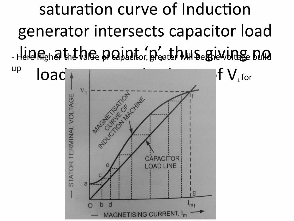
- This will continue as a cumulative process of voltage build up till the
saturation curve of Induction generator intersects capacitor load line at the point ‘p’, thus giving no
load generated voltage of V1 for
magnetizing current of Im
- Here higher the value of capacitor, greater will be the voltage build up
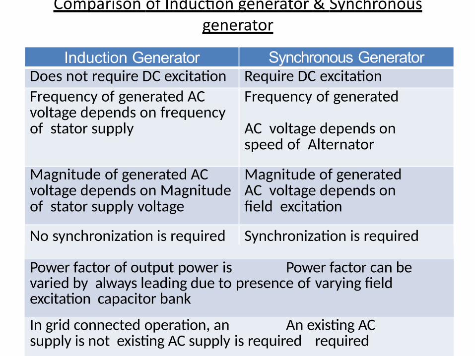
Comparison of Induction generator & Synchronous generator
Induction Generator Synchronous GeneratorDoes not require DC excitation Require DC excitation
Frequency of generated AC voltage depends on frequency of stator supply
Frequency of generated
AC voltage depends on speed of Alternator
Magnitude of generated AC voltage depends on Magnitude of stator supply voltage
Magnitude of generated AC voltage depends on field excitation
No synchronization is required Synchronization is required
Power factor of output power is Power factor can be varied by always leading due to presence of varying field excitation capacitor bank
In grid connected operation, an An existing AC supply is not existing AC supply is required required
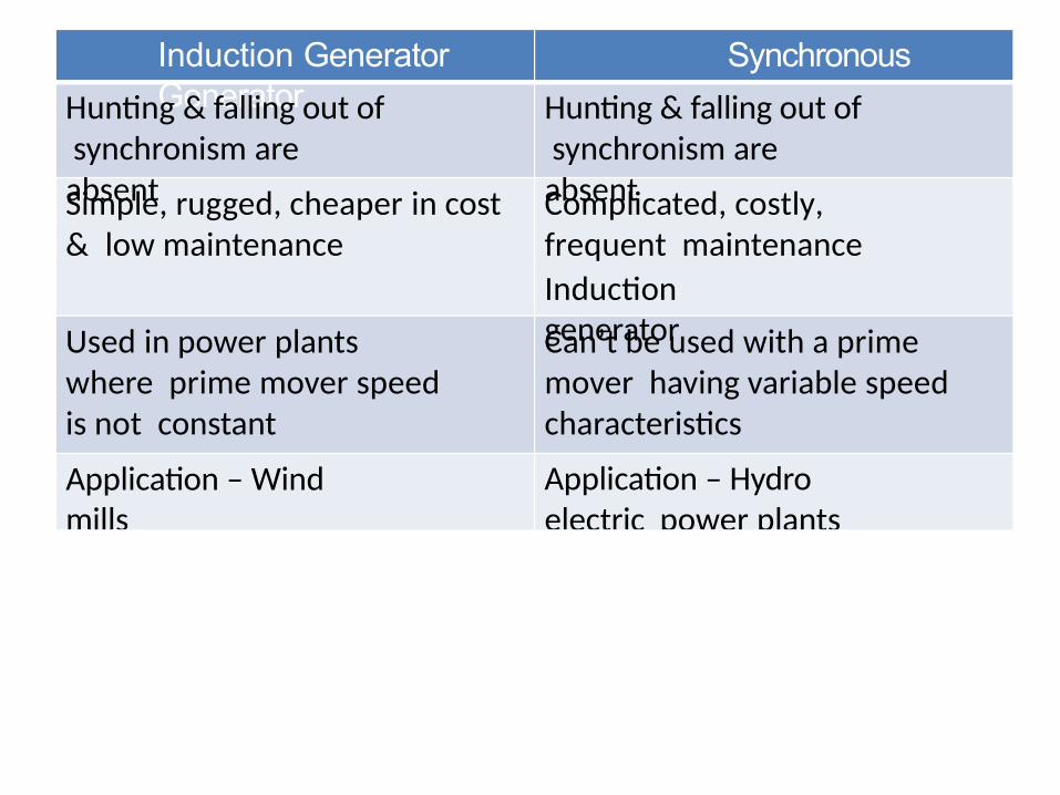
Induction Generator Synchronous GeneratorHunting & falling out of
synchronism are absent
Hunting & falling out of synchronism are absentSimple, rugged, cheaper in cost
& low maintenanceComplicated, costly,frequent maintenance compared toInduction generatorUsed in power plants
where prime mover speed is not constant
Can’t be used with a prime mover having variable speed characteristics
Application – Wind mills
Application – Hydro electric power plants
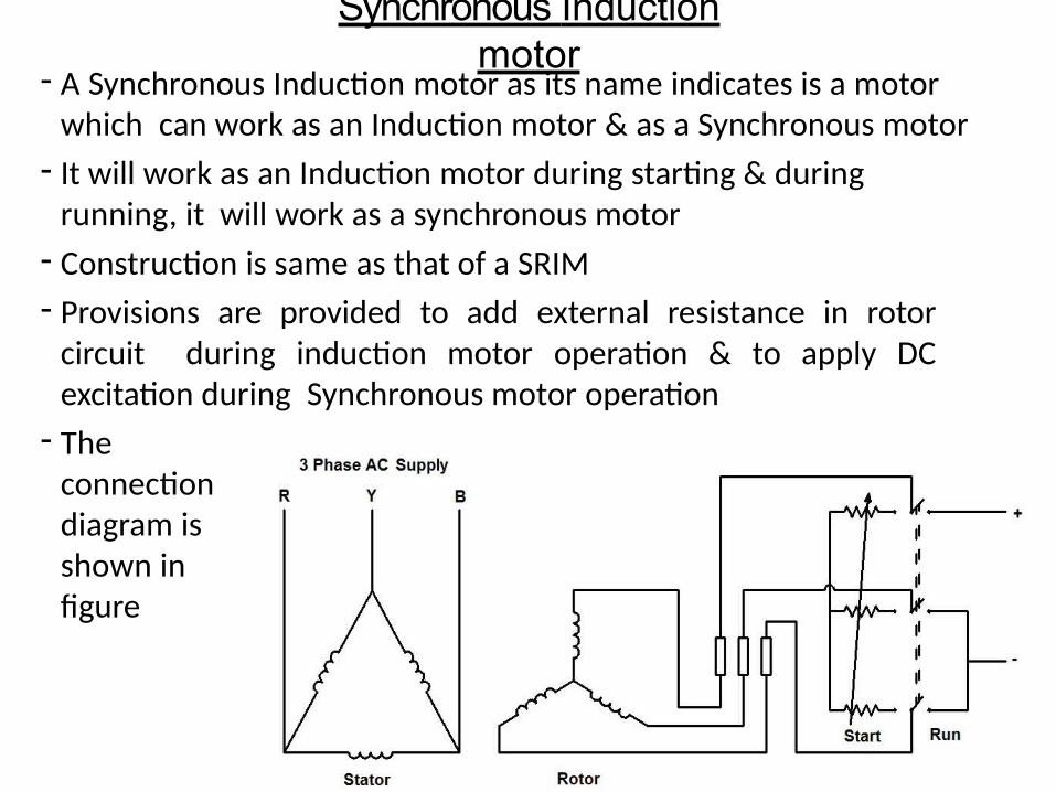
Synchronous Induction motor
- A Synchronous Induction motor as its name indicates is a motor which can work as an Induction motor & as a Synchronous motor
- It will work as an Induction motor during starting & during running, it will work as a synchronous motor
- Construction is same as that of a SRIM
- Provisions are provided to add external resistance in rotor circuit during induction motor operation & to apply DC excitation during Synchronous motor operation
- The connection diagram is shown in figure
- During starting, the switch is put to start position
- Now stator supply is given & machine is started as SRIM
- When machine is running at near synchronous speed, switch is put to run position
- Now a DC voltage is given to rotor & fixed magnetic poles are created in rotor
- Since the motor is running near synchronous speed, the rotor magnetic poles gets locked with stator rotating magnetic field poles & starts running as a synchronous motor
- This motor got the advantages of SRIM during starting (good starting torque & low starting current) & advantages of a Synchronous motor during running (Constant speed & adjustable power factor)
- It is used where high starting torque & constant speed is required
Single phase Induction motor- A Single phase Induction motor operates on 1 phase AC supply
- Used in homes, offices etc. where 1 phase AC supply is available- Construction of 1 phase Induction motor is almost same as that of a
3 phase SCIM- The main difference is that, stator contains only a 1 phase winding.
Rotor is a squirrel cage rotor- Unlike a 3 phase Induction motor, 1 phase Induction motor is not
self starting & requires some starting means- When a 1 phase AC supply is given to stator winding, an
alternating (pulsating) magnetic field is produced in stator & it links the rotor
- An EMF induces in rotor & a current flows through the rotor conductors
- Now the rotor conductors are like a current carrying conductor placed in a magnetic field & it experiences a torque
- The torque produced in rotor is also pulsating in nature. So net torque is zero & 1 phase Induction motor is not self starting
- If rotor is rotated in one direction by some mechanical means, it will continue to run in the direction of rotation
- So 1 phase Induction motor require some starting means due to lack of starting torque
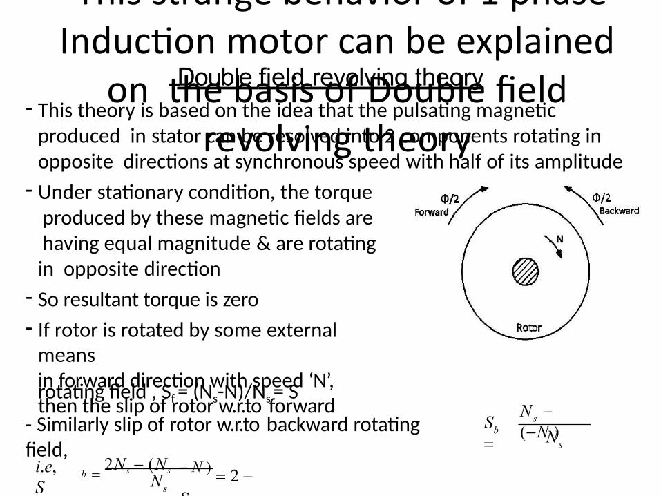
- This strange behavior of 1 phase Induction motor can be explained
on the basis of Double field revolving theory
Double field revolving theory- This theory is based on the idea that the pulsating magnetic
produced in stator can be resolved into 2 components rotating in opposite directions at synchronous speed with half of its amplitude
- Under stationary condition, the torque produced by these magnetic fields are having equal magnitude & are rotating in opposite direction
- So resultant torque is zero
- If rotor is rotated by some external meansin forward direction with speed ‘N’, then the slip of rotor w.r.to forwardrotating field , Sf = (Ns-N)/Ns = S
- Similarly slip of rotor w.r.to backward rotatingfield, s
sb N
N (N )S
N 2Ns (Ns
s
N ) 2 S
bi.e,S
- For normal operation, (2-s)>s- So the current induced by backward rotating field is much larger
& power factor is low- This current induces an EMF in stator & produces a MMF
which opposes backward rotating field & its magnitude decreases
- On the other hand, current induced by forward rotating field is low & power factor is high
- This low current produces an a low value MMF which opposes the forward rotating field
- Now the magnitude of forward field is higher compared to magnitude of backward field
- This will continue as speed increases in forward direction- At near synchronous speed, forward field may be several times
the backward field. As a result there is a net running torque- The T-Speed characteristics of 1 phase motor is the resultant of
T- Speed characteristics of forward & backward rotating fields- It is shown in figure- When S = 1, resultant torque is zero- For other values of slip, motor produces a net torque
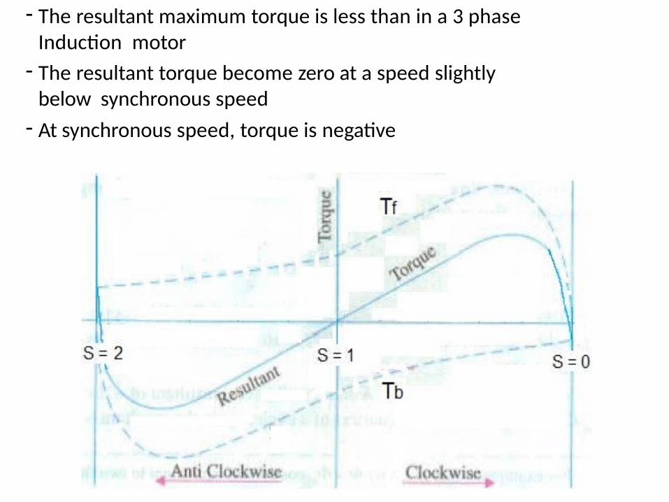
- The resultant maximum torque is less than in a 3 phase Induction motor
- The resultant torque become zero at a speed slightly below synchronous speed
- At synchronous speed, torque is negative
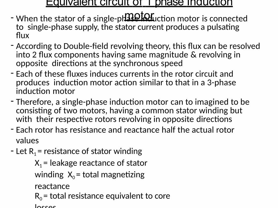
Equivalent circuit of 1 phase Induction motor- When the stator of a single-phase induction motor is connected
to single-phase supply, the stator current produces a pulsating flux
- According to Double-field revolving theory, this flux can be resolved into 2 flux components having same magnitude & revolving in opposite directions at the synchronous speed
- Each of these fluxes induces currents in the rotor circuit and produces induction motor action similar to that in a 3-phase induction motor
- Therefore, a single-phase induction motor can to imagined to be consisting of two motors, having a common stator winding but with their respective rotors revolving in opposite directions
- Each rotor has resistance and reactance half the actual rotor values
- Let R1 = resistance of stator winding
X1 = leakage reactance of stator
winding X0 = total magnetizing
reactanceR0 = total resistance equivalent to core
lossesR2' = resistance of the rotor referred to
the statorX2' = leakage reactance of the rotor
referred to the stator
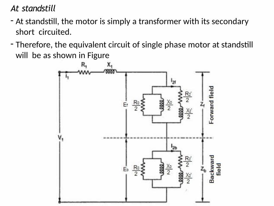
At standstill- At standstill, the motor is simply a transformer with its secondary
short circuited.
- Therefore, the equivalent circuit of single phase motor at standstill will be as shown in Figure
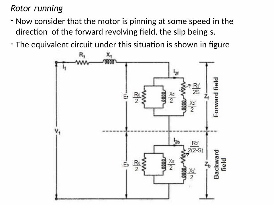
Rotor running- Now consider that the motor is pinning at some speed in the
direction of the forward revolving field, the slip being s.
- The equivalent circuit under this situation is shown in figure
Making 1 phase Induction motor self starting
- 1 phase Induction motor is not self starting & if the rotor is rotated in one direction by some external means, it will continue to run in the direction of rotation
- This method of starting is undesirable & require some method for creating a rotational magnetic field & make the motor self starting
- This can be achieved by converting 1 phase supply into 2 phase supply by providing an additional winding called auxiliary/starting winding
- Once the motor has achieved sufficient speed, the additional windings can be disconnected & the motor will continue to rotate
- Depending on the method employed for making the motor self starting, 1 phase Induction motors are classified into
a) Split phase motor – started by 2 phase motor action through the use of a starting winding
b)Capacitor motor - started by two-phase motor action through the use of an auxiliary winding and a capacitor
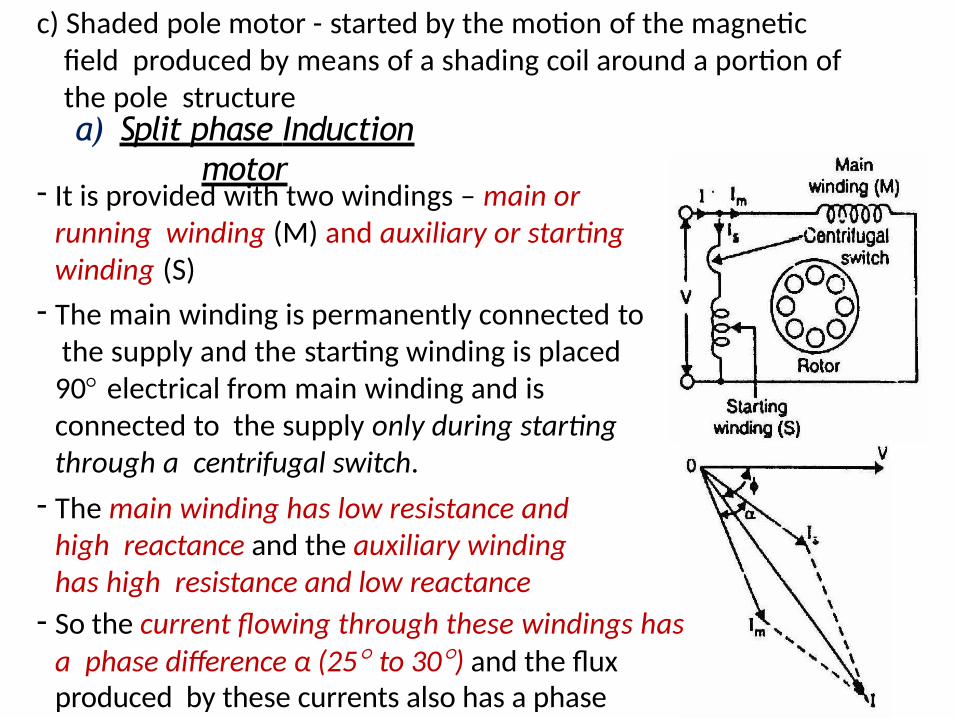
c) Shaded pole motor - started by the motion of the magnetic field produced by means of a shading coil around a portion of the pole structurea) Split phase Induction
motor- It is provided with two windings – main or
running winding (M) and auxiliary or starting winding (S)
- The main winding is permanently connected to the supply and the starting winding is placed 90 electrical from main winding and is connected to the supply only during starting through a centrifugal switch.
- The main winding has low resistance and high reactance and the auxiliary winding has high resistance and low reactance
- So the current flowing through these windings has a phase difference α (25 to 30) and the flux produced by these currents also has a phase difference α.
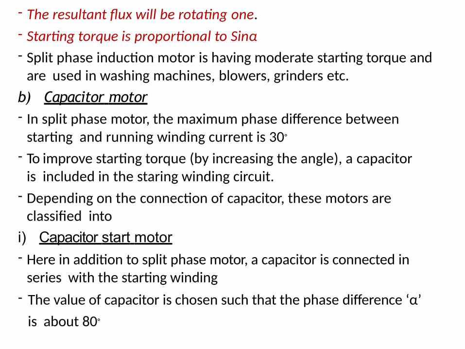
- The resultant flux will be rotating one.
- Starting torque is proportional to Sinα
- Split phase induction motor is having moderate starting torque and are used in washing machines, blowers, grinders etc.
b) Capacitor motor- In split phase motor, the maximum phase difference between
starting and running winding current is 30◦
- To improve starting torque (by increasing the angle), a capacitor is included in the staring winding circuit.
- Depending on the connection of capacitor, these motors are classified into
i) Capacitor start motor- Here in addition to split phase motor, a capacitor is connected in
series with the starting winding
- The value of capacitor is chosen such that the phase difference ‘α’
is about 80◦
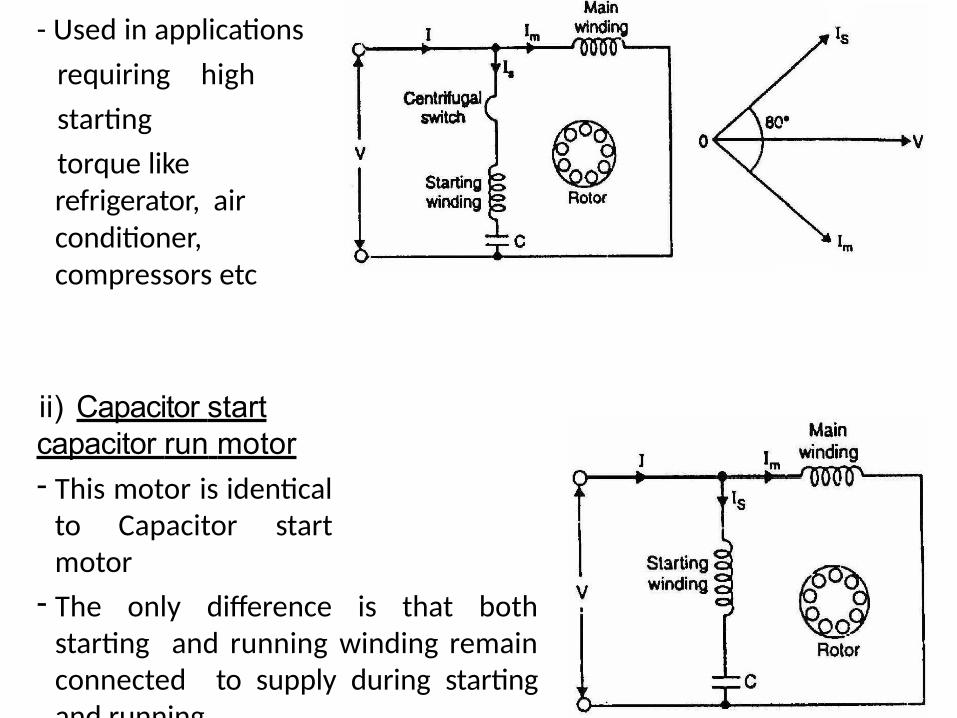
- Used in applications
requiring high
starting
torque like refrigerator, air conditioner, compressors etc
ii) Capacitor start capacitor run motor- This motor is identical
to Capacitor start motor
- The only difference is that both starting and running winding remain connected to supply during starting and running.
- Two designs are generally used
Design 1- Here a single capacitor is used for
both starting and running
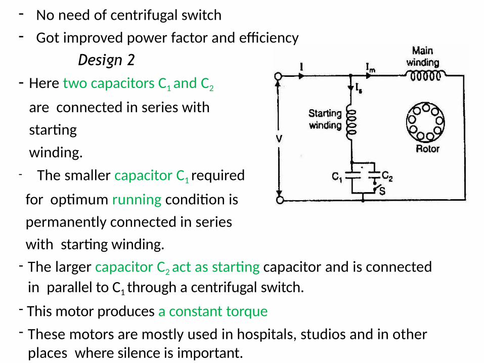
- No need of centrifugal switch
- Got improved power factor and efficiency
Design 2- Here two capacitors C1 and C2
are connected in series with
starting
winding.
- The smaller capacitor C1 required
for optimum running condition is
permanently connected in series
with starting winding.
- The larger capacitor C2 act as starting capacitor and is connected
in parallel to C1 through a centrifugal switch.
- This motor produces a constant torque
- These motors are mostly used in hospitals, studios and in other places where silence is important.
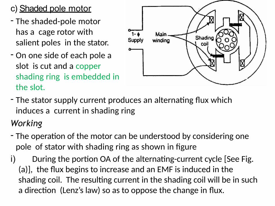
c) Shaded pole motor- The shaded-pole motor
has a cage rotor with salient poles in the stator.
- On one side of each pole a slot is cut and a copper shading ring is embedded in the slot.
- The stator supply current produces an alternating flux which induces a current in shading ring
Working- The operation of the motor can be understood by considering one
pole of stator with shading ring as shown in figure
i) During the portion OA of the alternating-current cycle [See Fig. (a)], the flux begins to increase and an EMF is induced in the shading coil. The resulting current in the shading coil will be in such a direction (Lenz’s law) so as to oppose the change in flux.
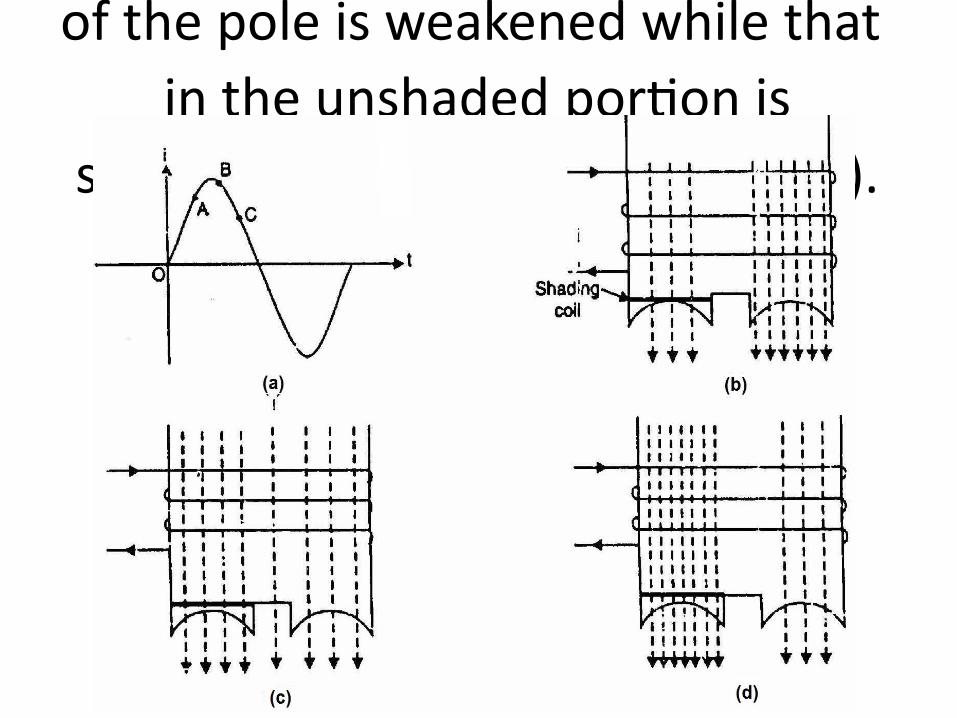
Thus the flux in the shaded portion
of the pole is weakened while that
in the unshaded portion is
strengthened as shown in Fig. (b).
ii) During the portion AB of the alternating-current cycle, the flux has reached almost maximum value and is not changing. Consequently, the flux distribution across the pole is uniform [See Fig. (c)] since no current is flowing in the shading coil
iii) As the flux decreases (portion BC of the alternating current cycle), current is induced in the shading coil so as to oppose the decrease in current. Thus the flux in the shaded portion of the pole is strengthened while that in the unshaded portion is weakened as shown in Fig. (d)
- This shifting flux is like a rotating weak field moving in the direction from unshaded portion to the shaded portion of the pole.
- The rotor is of the squirrel-cage type and is under the influence of this moving field.
- Consequently, a small starting torque is developed.- As soon as this torque starts to revolve the rotor, additional torque
is produced by single phase induction motor action.- The motor accelerates to a speed slightly below the
synchronous speed and runs as a single phase induction motor
- The salient features of this motor are extremely simple construction and absence of centrifugal switch.
- Since starting torque, efficiency and power factor are very low, these motors are only suitable for low power applications e.g., to drive: (a) small fans (b) toys (c) hair driers (d) desk fans etc.
- The power rating of such motors is upto about 30 W.