Embed Size (px)
Citation preview

SWR 1000 – An Advanced Boiling Water
Reactor with Passive Safety Features

SWR 1000 General Description
– March 2003 –

3
General Description
SWR 1000
Table of Contents
1 Introduction..........................................................................................................................7
2 Objectives of SWR 1000 Development ...............................................................................7
3 Basic Design Features of the SWR 1000 ............................................................................8
4 Plant Description..................................................................................................................9 4.1 Operation, Arrangement and Technical Data ......................................................................9 4.2 Nuclear Steam Supply System ..........................................................................................11 4.3 Steam, Condensate and Feedwater Cycle ........................................................................13 4.4 Passive and Active Accident Control Systems...................................................................14 4.5 Other Reactor Auxiliary Systems .......................................................................................24 4.6 Electrical and Instrumentation & Control Systems Concept...............................................27
5 Accident Sequences..........................................................................................................32 5.1 Accidents Without Loss of Coolant Inside the Containment (Transients) ..........................32 5.2 Accidents With Loss of Coolant Inside the Containment ...................................................32 5.3 Anticipated Transients Without Scram...............................................................................33 5.4 Severe Core Melt Accident ................................................................................................34 5.5 Conclusion.........................................................................................................................35
6 Probabilistic Safety Analyses.............................................................................................36
7 Civil Structures...................................................................................................................36 7.1 General Arrangement of Buildings.....................................................................................36 7.2 Reactor Building ................................................................................................................37 7.3 Other Buildings ..................................................................................................................37

5
General Description
SWR 1000
Abbreviations AC Alternating Current
ATWS Anticipated Transients without Scram
BWR Boiling Water Reactor
CCC Containment Cooling Condenser
CPU Communication Processor Unit
CRD Control Rod Drive
DC Direct Current
EC Emergency Condenser
EPR European Pressurized Water Reactor
FU Function Unit
FW Feedwater
GRS Gesellschaft für Reaktorsicherheit
HP High Pressure
I&C Instrumentation and Control
LOCA Loss of Coolant Accident
LP Low Pressure
MCR Main Control Room
MSIV Main Steam Isolation Valve
MSL Main Steam Line
NI Nuclear Island
PAMS Post Accident Monitoring System
PAR Passive Autocatalytic Recombiner
PPPT Passive Pressure Pulse Transmitter
PSA Probabilistic Safety Assessment
PWR Pressurized Water Reactor
RHR Residual Heat Removal
RPS Reactor Protection System
RPV Reactor Pressure Vessel
RRP Reactor Water Recirculation Pump
RSK (German) Reactor Safety Commission
RSS Remote Shutdown Station
SG Switchgear
TI Turbine Island

7
General Description
SWR 1000
1 Introduction The SWR 1000 blends years of experience in design, construction and operation of BWRs with new concepts to achieve an optimum blend of increased safety and reduced costs. It has been developed to provide a reliable source of economically competitive, safe electricity. The SWR 1000 is a medium-capacity boiling water reactor. It is an evolutionary development based on the experience gained with the proven engineering of current-generation BWR plants supplemented by an innovative approach that entails the partial replacement of active safety sys-tems with passive safety features. The passive safety systems utilize basic laws of physics, such as gravity, enabling these systems to function without electrical power supply or actuation by powered instrumentation and control (I&C) systems. The new concepts provide passive protection of the core without operator intervention for up to three days while minimizing the costs and com-plexities associated with today’s active safety systems concepts. Development at Framatome ANP of a new BWR plant concept began in early 1992 with an ap-proximate capacity rating of 650 MW. This concept phase was completed in the fall of 1993, while the subsequent consolidation phase reached completion by mid-1995. The multi-year design phase, carried out in consultation with the German Reactor Safety Commission (RSK), has been under way since mid-1995. In parallel with the design phase, an experimental testing program has been conducted at Frama-tome ANP’s own testing facilities and at other research centers to provide verification of the func-tion and effectiveness of the SWR 1000's passive safety systems.
2 Objectives of SWR 1000 Development The overall objective was to develop an economically competitive plant while achieving higher levels of safety than the existing fleet of commercial nuclear power plants and reducing or elimi-nating the risks associated with licensing and construction of a new nuclear power plant. a.) Economic Competitiveness
Nuclear power plants can only be economically competitive if power-generation costs (i.e. invest-ment costs plus operating, maintenance and decommissioning costs) are not higher than those for fossil-fired power plants (e.g., coal- or gas-fired units). The dominant cost factors to be considered in nuclear power plants are the amount of capital and the length of time the capital is not producing income, i.e. the construction and licensing period. The SWR 1000 design addresses all these factors by minimizing the total capital outlay, by mini-mizing the construction time and by offering a licensable design. By designing the plant to rely on passive and active systems for safety functions a significant re-duction in total plant cost has been realized. Active systems also require many more support sys-tems than passive systems. Savings can also be achieved by combining system functions, resulting in fewer systems. The SWR 1000 has eliminated some of the previously standard BWR systems by incorporating their functions into other systems thereby reducing the total number of systems. Maximizing plant availability is another technique that increases economic competitiveness. The SWR 1000 design achieves high availability through application of a wide range of experience gained from plants currently in service.

General Description SWR 1000
8
b.) High Level of Safety
The high safety standard of current nuclear power plants is based on a complex system of re-dundant active safety equipment and all of the support systems required for the functioning of these systems. Achieving this safety standard entails high capital costs and considerable expen-diture for operation and maintenance in terms of both personnel and equipment. The SWR 1000 design achieves higher levels of safety than the current fleet of operating plants while reducing the complexity of the safety systems through the use of “passive” safety equip-ment. As a result of this approach, the following attributes were realized:
− Clear and simple systems engineering
− Increased safety margins
− Slower reaction to off-normal conditions
− Increased grace periods (up to several days) after the onset of accident conditions before in-tervention by operating personnel is required
− Effect of human error on reactor safety is minimized or avoided entirely
− Much lower probabilities of occurrence of accidents leading to core melt
− The effects of a core melt accident are limited to the plant itself c.) Reduction of Risks Due to Licensing and Construction
All new passive systems have been tested either in full scale or in a scaled configuration and will be tested again with full-scale, prototype components. A European utility group successfully assessed compliance with the European Utility Require-ments. Framatome ANP has also initiated the process of obtaining a 10CFR part 52 Design Certi-fication from the US NRC for the SWR 1000 to eliminate the risks inherent in the 10CFR part 50 process for obtaining an operating license. The construction time for the SWR 1000 is greatly reduced from those experienced by the cur-rently operating fleet as a direct result of the simplification of systems and passive design basis. These two aspects of the design have resulted in fewer total components as well as significantly reducing the number of safety-classified components.
3 Basic Design Features of the SWR 1000 The SWR 1000 design includes many unique features that differentiate it from other designs. These key design features are as follows:
− Reactor core with low power density
− Large water inventory inside the reactor pressure vessel (RPV) to ensure good thermal-hydraulic behavior in the event of an accident, i.e. excellent slow-acting accident control capa-bilities
− Control of transients without coolant makeup to the RPV from an external source
− Large heat storage capacity inside the containment as a result of large water inventories in the core flooding pools and the pressure suppression pool
− Passive equipment for heat removal from the RPV and containment

9
General Description
SWR 1000
− Large flooding water inventory available inside the containment for discharge by gravity flow into the RPV following depressurization
− Passive actuation of key safety functions such as reactor scram, pressure relief and depressurization
− Passive accident control without power supply, without actuation by I&C systems and without intervention by operating personnel in the initial days following the onset of accident conditions
− Nitrogen-inerted containment atmosphere to preclude hydrogen combustion and hydrogen reactions inside the containment in the event of a serious core melt accident
− Extended containment pressure load-bearing capacity to accommodate the quantity of hydro-gen arising from 100 % zirconium oxidation in the event of a serious core melt accident
− Passive cooling of the RPV exterior in the event of core melt scenarios to ensure retention of the core melt inside the RPV
− Flexible operating cycle length (1 to 2 years) with high discharge burnup
− High plant availability (> 90 %) thanks to short plant downtimes for refueling, maintenance and servicing
− 48-month plant construction period
− 60-year plant service life.
4 Plant Description
4.1 Operation, Arrangement and Technical Data The plant (Figure 1) is equipped with a boiling water reactor to generate steam at a thermal output of 3370 MW. The satu-rated steam, at 75 bar, is routed through the HP turbine and the moisture separator reheater to the three-stage LP turbine. The gross electrical output is 1290 MWe. The steam leaving the low-pressure tur-bine sections is condensed into water in the main condensers. The condensate is returned to the reactor by condensate and feedwater pumps via a condensate cleanup system and a feedwater heating train (see Section 4.3 for details). The systems and components are arranged inside the various plant buildings and structures (Fig-ure 2), creating clearly delineated structural complexes thereby enabling the buildings to be con-structed in parallel. The reactor building and the turbine building comprise the center of the plant. Other buildings are the switchgear building, the reactor auxiliary building and the reactor support-ing systems building, the emergency control room building, the circulating water pump building, the service water pump building and emergency diesel generator building and the complex with the second service water pump building and emergency diesel generator building.
Figure 1: Basic Diagram of SWR 1000

General Description SWR 1000
10
Figure 2: Typical Site Layout Table 1 presents the key technical data for the SWR 1000 in comparison with those of a tradi-tional 1300-MW BWR plant.
Data SWR 1000 1300 MW BWR*
Overall plant − Thermal output − Gross electric output − Net electric output − Net efficiency
MW MW MW %
3370
~ 1290 ~ 1250 ~ 37
3840 1428 1373 35.7
Reactor core − No. of fuel assemblies − Active height of core − Average power density
- m
kW/l
664 3.0 51.0
784 (10x10)
3.74 56.8
Reactor pressure vessel − Inside height − Inside diameter − Design pressure − No. of recirculation pumps
m m
bar -
23.45 7.12 88.3
8
22.35 6.62 87.3
8 Turbine − Number − No. of HP/LP casings
- -
1
1/3
1
1/2 Containment − Inside diameter − Inside height − Design pressure − Drywell volume + gas volume of core flooding pool − Water volume of pressure suppression pool − Gas volume of pressure suppression pool − Water volume of core flooding pool
m m
bar-abs m3 m3 m3 m3
32.00 33.7 3.5
6400 2900 5400 3200
29
32.5 5.3
8200 3100 6000
-
− Plant design life − Plant construction period
years months
60 48
40 60
Table 1: Key technical data of SWR 1000 compared to an advanced 1300-MW BWR plant * Framatome ANP’s Gundremmingen Nuclear Power Station, Unit B+C
Switchgear building
Reactor building
Turbine building
Reactor supporting systems building
Service water pump building and Emergency diesel generator building
Circulating water pump building Service water pump building and Emergency diesel generator building
Reactor auxiliary building

11
General Description
SWR 1000
4.2 Nuclear Steam Supply System The nuclear steam supply system is located in the reactor building and is surrounded by a steel-reinforced concrete containment equipped with a steel liner.
4.2.1 Reactor Core and Fuel Assemblies The SWR 1000 core represents an evolutionary development of previous standard BWR core designs. While no fundamental changes have been made to the basic structure of the BWR core design, certain modifications have been introduced. These modifications include reducing the active height of the core and increasing the size of the fuel assemblies. By reducing the active core height, the core can be positioned lower inside the RPV. As a result, there is a greater water inventory available inside the RPV above the core, which facilitates tran-sient control. The aforementioned modification of the fuel assemblies consists of enlarging the existing ATRIUMTM10 fuel assembly design (10x10-9Q) to a 12x12-16Q (ATRIUMTM12 fuel assembly) rod configuration. Fuel rod diameter and pitch, on the other hand, remain unchanged from the ATRIUMTM10 fuel assembly. As a result of this new design, there are fewer core fuel assemblies. This reduces handling times during refueling and also reduces the number of control rods, control rod drives, and in-core instrumentation assemblies and power distribution detectors. The average power density of the core has been reduced. This reduction, together with the ad-vanced fuel assembly design, helps to ensure good plant behavior during transients. Flexible operating cycles are planned for the SWR 1000. For example, the core can be operated in annual cycles or in cycles lasting anywhere from one to two years. All of these core design attributes contribute to the economic efficiency of SWR 1000 operation.
4.2.2 Reactor Pressure Vessel and Internals The reactor pressure vessel (RPV) (see Figure 3) encloses the reactor core and the RPV inter-nals. The main dimensions of the RPV are comparable to those of a 1300 MW BWR (see Ta-ble 1). As a result of this large volume, and due to the low positioning of the core inside the RPV, core uncovery does not occur in the event of automatic depressurization, even without coolant makeup. The core shroud as well as the upper and lower core grids mainly serve to align the core, the con-trol rods, the in-core instrumentation and to guide core flow. Steam separators and steam dryers are installed in the RPV to separate the steam-water mixture leaving the core. A chimney is lo-cated between the core and the steam separators. All RPV internals are designed to allow removal and replacement as needed. The RPV is supported by a frame mounted around the top half of the RPV. The RPV internals, such as the core shroud, upper and lower core grid, steam separators and steam dryers, for ex-ample, are essentially based on the proven technology used in Framatome ANP’s 1300 MW BWR design.

General Description SWR 1000
12
4.2.3 Reactor Water Recirculation Pumps The reactor water recirculation pumps (RRP) provide flow of coolant through the core. Com-parative studies of natural and forced coolant circulation in the RPV have shown that it is advantageous to retain the forced circulation flow. The forced circulation provides better fuel utilization and load cycling capability when compared to natural circulation designs. The SWR 1000 design utilizes eight internal RRPs. The SWR 1000 reactor water recirculation pumps are wet rotor pumps, thereby eliminat-ing the need for mechanical seals. This design offers certain operational advantages, and has been proven in Swedish and Finnish BWR plants.
4.2.4 Control Rod Drives The SWR 1000 retains the fine motion control rod drive design proven by operating experi-ence at all existing Framatome ANP BWR plants. The electric motor drive unit and the hydraulic drive unit are installed and removed from the control rod drive compartment below the RPV.
4.2.5 Fuel Assembly Handling and Storage The SWR 1000 equipment and plant structures used for refueling, storage of new and spent fuel assemblies, and handling of reactor components do not deviate significantly from the equipment and plant structures in the existing fleet of BWR nuclear power plants.
4.2.5.1 Storage of New Fuel Assemblies
New fuel assemblies are stored in the new fuel storage area, which is located adjacent to the spent fuel storage pool. The new fuel assemblies are placed in dry storage racks that can ac-commodate up to one reload batch of new fuel.
4.2.5.2 Spent Fuel Storage Pool
Spent fuel assemblies are stored in the water-filled fuel pool located in the reactor building. The pool water ensures residual heat removal and provides shielding. Subcriticality is maintained by designing the storage racks with a sufficiently large fuel assembly storage pitch and by equipping them with special neutron absorbers. Racks for storage of control rods and RPV internals (such as in-core instrumentation assemblies, neutron sources, etc.) are provided in addition to the fuel assembly storage racks. Total storage capacity allows accommo-dation of spent fuel assemblies from seven cycles of operation plus the fuel assemblies of the core.
Figure 3: Reactor Pressure Vessel

13
General Description
SWR 1000
4.3 Steam, Condensate and Feedwater Cycle Similar to the boiling water reactors in operation today, the SWR 1000 operates according to the direct-cycle principle (Figure 4). The live steam generated in the RPV passes directly to the dou-ble-flow high-pressure (HP) section of the steam turbine via three (instead of the previous four) main steam lines fitted with combined stop and control valves. After undergoing partial expansion in the HP turbine section, the steam passes through a moisture separator/reheater to the three double-flow low-pressure (LP) sections of the turbine.
Figure 4: Steam, Condensate and Feedwater Cycle The condensate is removed from the condensers of the three LP turbine sections and returned to the RPV at a temperature of 220 °C via the feedwater heating system. This system consists of a condensate cleanup system, LP feedwater heaters, HP feedwater heaters and condensate and feedwater pumps.

General Description SWR 1000
14
4.4 Passive and Active Accident Control Systems
4.4.1 Overview The primary objectives in developing the SWR 1000 were to develop a cost competitive plant with enhanced safety. These often contradictory objectives were met by introducing passive systems (Figure 5) for performing safety-related functions in the event of transients or accidents. Com-pared to the fleet of currently operating reactors, the technology employed in these systems is much simpler, operation is independent of a power supply, activation by I&C systems is not re-quired, and fewer supporting systems are required.
Figure 5: Passive Shutdown, Core Flooding and Residual Heat Removal Systems Passive systems are characterized by the fact that they utilize the laws of nature (e.g. gravity, pressure differentials) to perform their designated safety functions and dispense with active com-ponents (e.g. motor driven valves and pumps). The most frequent events requiring system function (maintaining reactor coolant inventory in the RPV and residual heat removal) comprise anomalies in plant operation, so-called transients. In the event of a loss-of-coolant accident (LOCA), actions to inject water into the RPV are necessary to prevent core uncovery. In both types of events, the residual heat is removed from the contain-ment to the shielding/storage pool located outside the containment via the containment cooling condensers.

15
General Description
SWR 1000
The following safety functions must be assured for most transients as well as in the event of acci-dents:
− Reactor scram
− Containment isolation
− RPV pressure relief and depressurization
− Heat removal from the RPV
− Control of reactor coolant inventory (RPV level)
− Heat removal from the containment. The passive and active systems planned for these tasks are described below. Table 2 gives an overview and shows the redundancies of the systems (both active and passive) installed to control the individual accident scenar-ios. The passive safety equipment is capa-ble of controlling any postulated tran-sient conditions arising during power operation. There is no unallowable in-teraction between active and passive safety systems for transient control.
4.4.2 Containment and Passive Safety Features
4.4.2.1 Containment
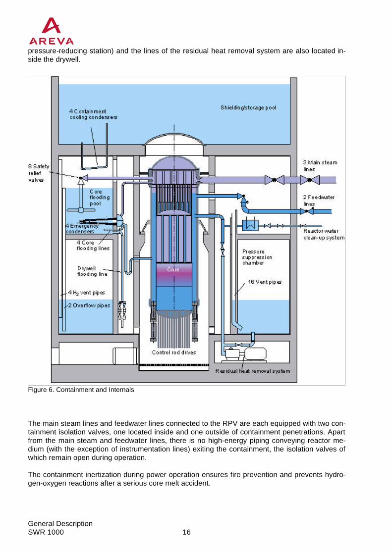
The primary function of the containment is to protect the environment against any release of ra-dioactive materials under all accident conditions. Like all other recent-generation BWR plants, a cylindrical containment made from steel-reinforced concrete equipped with an inner steel liner and pressure suppression system was selected (Fig-ure 6). The containment is divided into a drywell and a pressure suppression chamber, as re-quired by the pressure suppression system. The containment design also takes into account the hydrogen release from a postulated 100 % oxidation of the zirconium present in the RPV in the event of a core melt accident. Drywell In addition to the RPV and the three main steam lines and two feedwater lines, the following com-ponents are located in the drywell: four large hydraulically-linked core flooding pools, the emer-gency condensers and containment cooling condensers for passive heat removal, the flooding lines for passive flooding of the RPV and the passive pressure pulse transmitters for initiation of safety functions. In addition, the drywell is equipped with two 100 %-capacity recirculation air cooling systems. The high-pressure part of the reactor water cleanup system (HP cooler and
Table 2: Passive and Active Accident Control Systems
General Description SWR 1000
16
pressure-reducing station) and the lines of the residual heat removal system are also located in-side the drywell.
Figure 6. Containment and Internals The main steam lines and feedwater lines connected to the RPV are each equipped with two con-tainment isolation valves, one located inside and one outside of containment penetrations. Apart from the main steam and feedwater lines, there is no high-energy piping conveying reactor me-dium (with the exception of instrumentation lines) exiting the containment, the isolation valves of which remain open during operation. The containment inertization during power operation ensures fire prevention and prevents hydro-gen-oxygen reactions after a serious core melt accident.

17
General Description
SWR 1000
The residual heat removal pumps and heat exchangers are installed in separate compartments located underneath the pressure suppression chamber outside the containment. The compart-ments are not inerted and are accessible from the outside at all times for maintenance and servic-ing. This design ensures that any leak in the residual heat removal system does not lead to a loss of the water inventory stored in the containment. The design also ensures that operation of the residual heat removal system is not adversely impacted after the onset of accident conditions. One of the key differences between the containment of a standard BWR plant and that of the SWR 1000 lies in the latter’s ability to store residual heat inside the containment over a longer period. As a result, it is not necessary for operators to initiate any actions until several days after the onset of accident conditions. Pressure Suppression Chamber The pressure suppression chamber performs the following tasks:
− acts as a heat sink in the event of accident conditions
− provides a water inventory for RPV makeup via the residual heat removal system. As part of the pressure suppression system, the pressure suppression chamber is located be-tween the outer and inner cylinder below the core flooding pools (Figure 6) and is one-third filled with water. The pressure suppression chamber is connected to the drywell via vent pipes embed-ded into the concrete of the inner cylinder. In addition, the pressure suppression chamber and core flooding pools are connected to each other via submerged water overflow and hydrogen overflow pipes. The pressure-equalizing dampers (check valves) in existing BWR plants between the drywell and the air space of the pressure suppression chamber are eliminated. Core Flooding Pools The interconnected core flooding pools act as a heat sink for the emergency condensers and the safety relief valve system. In addition, the water in the core flooding pools is used for passive flooding of the reactor core following RPV depressurization in the event of a LOCA. In this function, spring check valves automatically open the flooding lines (Figure 7). In the event of a serious core melt accident, the water in-ventory in the core flooding pools is used for cooling the RPV from the outside. The core flooding pools are located above the pressure suppression chamber, and are approximately two-thirds filled with water. The physical separation of the core flood-ing pools is achieved via four plant compartments in which components, piping and ventilation units are located (Fig-ure 19). Each core flooding pool houses an emergency condenser, a containment cooling condenser (above the water level), a RPV flooding line connec-tion, and the relief lines of the safety relief valves with steam quenchers. In addition, a flooding line for external RPV cooling leads from one of the core flooding pools into the bottom part of the drywell.
Figure 7: Core Flooding by Gravity Flow

General Description SWR 1000
18
4.4.2.2 Safety Relief Valve System
The tasks of the safety relief valve sys-tem are as follows:
− Protection of the reactor coolant pressure boundary against pressure in excess of allowable limits (pres-sure relief)
− Automatic depressurization of the RPV in the event that the RPV level falls below specified values or in the event of a pressure rise in the con-tainment (LOCA in the containment)
− Short-term removal of excess steam in the event of turbine trip and load shedding
− Depressurization for severe accident mitigation to prevent high pressure melt ejection.
The safety relief valve system is located inside the containment and consists of the safety relief valves and relief lines with steam quenchers, which are installed in the core flooding pools (Fig-ure 8). This system follows proven system concepts used in the existing Framatome-ANP BWR plants. The SWR 1000 has the following features that differ from earlier concepts:
− Four of the eight main valves are designed according to the pressurization principle, but for diversity reasons, the four others are designed according to the depressurization principle.
− The main valves are actuated for ‘Automatic Depressurization of RPV’ by solenoid pilot valves as well as by diaphragm pilot valves via the passive pressure pulse transmitters. This means that depressurization, together with the pressure relief function, can be initiated via pilot valves without need for actuation by an I&C system. Standard passive spring-loaded valves are also used to initiate the pressure relief function.
− The relief lines and their steam quenchers do not lead to the pressure suppression pool, but rather into the core flooding pools. All accidents lead to similar containment reactions since energy and, in the case of a core melt accident, non-condensable gases, are released into the drywell area.
Figure 8: RPV Safety Relief Valve System

19
General Description
SWR 1000
4.4.2.3 Emergency Condensers
The emergency condensers function as completely passive devices for residual heat removal from the RPV to the core flooding pools. As a result, the need for HP injection systems is elimi-nated. The emergency condensers also function in part as a diverse means of depressurization. The emergency condenser system (Figure 9) consists of four separate sub-systems that together provide a rated heat transfer capacity of 4 x 66 MW at 75 bar reactor pres-sure. Each emergency condenser subsystem consists of a steam line (top connection) leading from an RPV nozzle, and a condensate return line (lower connection) back to the RPV. Each return line is equipped with an anti-circulation loop. The emergency condensers are connected to the RPV with no isolating element and are actuated by a drop in the RPV water level. The heat exchanger tubes fill with steam (which condenses) after the water level in the reactor drops below a certain level. The condensate returns to the RPV by grav-ity flow.
4.4.2.4 Containment Cooling Condensers
The containment cooling condensers (CCCs) remove residual heat passively from the contain-ment atmosphere to the shielding/storage pool located above the containment. The CCCs are actuated by rising temperatures in the containment. The system (Figure 10) consists of four CCCs, each with a rated thermal capacity of 4.8 MW. Each heat exchanger consists of tubes at a slight angle to horizontal. The condensers are connected to the shielding/storage pool via an inlet to the lower end and a discharge line at the higher end. The feed line and discharge line as well as the condenser tubes are filled with water from the shielding/storage pool. All connecting lines to the shielding/storage pool are open dur-ing plant operation. Since the system functions entirely passively as a function of the thermal gradients, no actuation is necessary for startup. The function of this new component was suc-cessfully verified at the integral PANDA test fa-cility at the Paul Scherrer Institute in Würenlin-gen (Switzerland) using large-scale components.
Figure 9: Emergency Condenser
Figure 10: Containment Cooling Condenser

General Description SWR 1000
20
4.4.2.5 Passive Pressure Pulse Transmitter
Passive pressure pulse transmitters (PPPTs) are installed in the SWR 1000 for safety-classified initiation operations. The PPPTs function without electric power supply, external media, or actua-tion via I&C signals. The PPPTs serve to initiate reactor scram, containment isolation of main steam lines, and automatic depressurization of the RPV. The actual valve operation is accom-plished using system fluids and valves with stored actuation energy. The PPPTs initiate the func-tions as a result of a drop in the RPV water level. The PPPT (Figure 11) consists of a small heat exchanger that is connected to the reactor via a non-isolatable pipe. At normal water level in the RPV, the primary side of the heat exchanger is filled with water, which results in no heat transfer taking place. When the RPV water level drops below a certain level , the primary side of the PPPT fills with steam, which condenses and drains back to the RPV. The water stored on the secondary side is thereby heated and partially evapo-rates, leading to a rapid pressure rise. The pressure rise triggers the safety functions via dia-phragm pilot valves. These devices function entirely inde-pendently, and are therefore a di-verse basis to the I&C equipment. Their integration into the plant’s sys-tems engineering is (two 2-out-of-2 configuration) such that spurious ac-tuation of a single PPPT does not lead to initiation of actions, but also such that loss of one PPPT cannot prevent initiation. As a new device, the functional capa-bility of the PPPT was tested in the emergency condenser test facility at Germany’s Jülich Research Center. The actuation pressure of 6 bar (gauge) was reached in < 10 seconds.
4.4.2.6 Passive Outflow Reducer
The task of the passive outflow reducer is to significantly reduce the discharge mass flow from the RPV in the event of a postulated break in the emergency condenser return line. The passive outflow reducer (Figure 12) is a passive component with no moving parts, which has a low flow resistance in the normal direction of operational flow. However, flow resistance in-creases by approximately two orders of magnitude when the direction of flow is reversed. The increase in flow resistance in the outflow direction is achieved as the flow is subjected to the maximum possible swirling. As a result of the swirling, the fluid flows through a much narrower ring-shaped cross-section. The result is that the flow component in the circumferential direction is considerably greater than in the axial direction.
Figure 11: Passive Pressure Pulse Transmitter

21
General Description
SWR 1000
When a passive outflow reducer is installed in RPV nozzles, the mass flow in the event of a pipe break is reduced to approximately 10 % of the value, which would result without the passive out-flow reducer.
Figure 12: Passive Outflow Reducer
This new device has been tested at Framatome ANP’s Power Generation Group's large valve test facility in Karlstein, Germany.
4.4.3 Reactor Shutdown Systems Diverse systems are available for shutdown of the reactor (Figure 13). These include the control rods, with their diverse drive systems (electric motor drive for operational shutdown processes, and hydrau-lic drive for reactor scram). The SWR 1000 is also equipped with a fast acting boron injec-tion system, which causes reactor shut-down independent from the control rods and is completely independent of control rod opera-tions. The scram system is based largely on the accumulator tank concept implemented in German BWR plants, whereby the energy required for fast control rod insertion by hydraulic means is stored in tanks under nitrogen pressure. The tank overpressure for the SWR 1000 uses steam pressure, much like a PWR pressurizer, to provide the required driving head. The water-filled tanks’ steam pressure blanket is generated by electric heaters in the upper area of each tank.
Figure 13. Shutdown Systems

General Description SWR 1000
22
This modification enables the reduction of the tank size, and prevents nitrogen from entering the RPV in the event of a malfunctioning tank isolation valve. The scram system of the SWR 1000 also differs from existing collector tank systems because the two ring lines are not interconnected. Each ring line is supplied by two scram tanks, and supplies half of the control rod drives. Insertion of half of the control rods is sufficient to bring the core rap-idly to the ‘hot sub-critical’ condition. This means that the connections between the two ring lines are eliminated, and the system remains separated into two redundant subsystems. Each scram tank has the capacity to insert half of the control rods within the required time. During power op-eration the tanks are each isolated via a quick-opening valve. Tripping of the scram function is initiated via solenoid pilot valves or via parallel diaphragm pilot valves that are actuated by PPPTs. The fast acting boron injection system is also based on the pressure tank concept: The quantity of pentaborate solution required for hot and cold sub-criticality is stored in a tank and injected into the RPV.
4.4.4 Containment Isolation of Main Steam Lines The main steam lines are equipped with isolation valves positioned inside and outside the con-tainment at the containment penetrations. The system-fluid-actuated valves are of diverse design; the valve inside the containment is a quick-closing gate-type design, while the external valve is a quick-closing angle valve. Containment isolation is initiated, as in existing BWR plants, via safety I&C systems. In addition to the normal active isolation initiation, passive initiation is provided for the SWR 1000 via parallel diaphragm pilot valves that are actuated by PPPTs.
4.4.5 Residual Heat Removal and Active Core Flooding Systems The SWR 1000 concept includes two active low-pressure core flooding and residual heat removal systems, which are comparable to the systems in existing BWR plants in terms of their range of tasks (Fig. 14).
Fig. 14: Active Core Flooding and Residual Heat Removal Systems

23
General Description
SWR 1000
These systems perform the following tasks:
− Reactor cooling during operational shutdown and in the shutdown condition
− Water transfer operations prior to and subsequent to refueling
− Operational heat removal from the core flooding pools and pressure suppression pool water
− Heat removal from the containment in the event of loss of the main heat sink by cooling the pressure suppression pool and core flooding pool water
− Low-pressure feed of coolant to the RPV and simultaneous heat removal in the event of a loss-of-coolant accident.
The systems are actuated via safety I&C systems and system-associated electrical loads are con-nected to the emergency power supply system. High-pressure injection systems for the RPV are no longer required in the SWR 1000 design due to installation of the emergency condensers (cf. Section 4.4.2.3). As in existing BWR plants, the RHR system is cooled by a closed cooling water system for reac-tor services, which is cooled in turn by a secured service water system. The difference with re-spect to existing BWR plants lies in the fact that each closed cooling water system is divided into two system areas, which are cooled by a common closed cooling water heat exchanger. One sys-tem area and its closed cooling water pump, is continuously in operation and supplies the fuel pool coolers and other safety-classified cooling loads such as the water chillers and component coolers. The other system area, with the larger closed cooling water pump, is only activated if needed and supplies the residual heat removal heat exchanger, the diesel coolers and other as-sociated component coolers, such as recirculating air cooling devices for pumps. The closed cool-ing water systems (pumps, closed cooling water heat exchanger) are not located in the reactor building, as previously, but in the two service water pump buildings. The closed cooling water lines are routed into the reactor building via pipe and cable ducts. This has the advantage that no service water (river water or seawater) is fed into the reactor building, thereby ruling out submer-gence (flooding) accidents. Each service water pump supplies the dedicated closed cooling water heat exchanger with cool-ing water. These pumps are also located in the service water pump building, and, like the closed cooling water systems, are also protected against natural and external man-made hazards.
4.4.6 Systems for Control of Severe Core Melt Accidents Loss of all active and passive injection functions is assumed for the postulated severe core melt accident. To control this serious accident scenario the following additional mitigation systems are planned for the SWR 1000 and the plant is designed to withstand the consequences of the acci-dent: Core melt at high pressure is ruled out by the design of the depressurization system. The core melt is retained in the RPV at low pressure owing to cooling of the RPV exterior. A flooding sys-tem is installed for this purpose which feeds into the lower area of the drywell from the core flood-ing pools (Fig. 15). The flooding system is permanently isolated and activated upon challenge. The steam arising from cooling of the RPV from the outside is condensed at the CCCs that trans-fer the heat from the containment to the water of the shielding/storage pool. Refilling of the shielding/storage pool, which only becomes necessary several days after the onset of accident conditions, enables virtually unlimited heat removal.

General Description SWR 1000
24
The containment design considers the pressure buildup due to the hydrogen arising from a zirconium-water reaction of 100% of the zir-conium inventory present in the core. Hydrogen release always occurs via the drywell, and hydro-gen is also partly flushed into the pressure suppression chamber depending on the given pressure conditions. Any further pressure buildup due to detonation or defla-gration of the hydrogen is not pos-sible, as the containment is inerted with nitrogen. Long-term pressure relief in the containment after the onset of ac-cident conditions is effected via the gaseous waste processing system already installed in all current BWR plants, with catalytic hydrogen re-combination. All containment gases as well as the liquids formed during hydrogen recombination are returned to the containment.
4.5 Other Reactor Auxiliary Systems
4.5.1 Fuel Pool Cooling System The fuel pool must be cooled, independent of reactor operation, for as long as residual heat re-moval from spent fuel assemblies is needed. Two external fuel pool-cooling trains are installed for residual heat removal in existing BWR plants. In contrast to this, two redundant cooler units, each consisting of four heat exchangers operating in parallel, are installed in the spent fuel storage pool of the SWR 1000. The spent fuel storage pool water is cooled by natural convection. Redundancy is ensured by connecting the cooler units to the redundant closed cooling water systems backed up by emergency power supply. The tube-type coolers are arranged on the fuel pool wall in such a manner that defined water flows are ob-tained.
4.5.2 Reactor Water and Spent Fuel Storage Pool Cleanup System In the SWR 1000, unlike in previous BWR plants, a low-pressure concept is used (standard prac-tice in pressurized water reactor plants) for the reactor water cleanup system. In the SWR 1000 application, a regenerative heat exchanger and a pressure reducing station are arranged inside the containment, while an additional cooler and powdered resin pre-coat filters are located out-side the containment (Figure 16). The cleaned water is conveyed back into the containment by two return pumps and fed into the RPV via the regenerative heat exchangers. The two recirculat-ing pumps also convey the control rod drive flushing water and the reactor water recirculation pump sealing water. In addition, they are used as booster pumps for filling the scram tanks.
Fig. 15 Cooling of RPV Exterior in the Event of Core Melt

25
General Description
SWR 1000
The advantage of this concept lies in the fact that the filters and the low-pressure cooler can be positioned outside the containment, thereby reducing the total number of containment penetra-tions. In addition, the filters, now located in the reactor building, can also be used for cleanup of the spent fuel storage pool water and the water in the shielding/storage pool.
Figure 16. Reactor Water and Spent Fuel Storage Pool Cleanup System This involves extracting the water via connections just below the surface of the water in the pool, and injecting it back into the pool after cleanup. The connections are distributed around the edge of the pool such that uniform cleanup of the pool is ensured. This means that the cleanup system otherwise normally used for this purpose is no longer necessary. During plant operation, only one filter is used for reactor water cleanup, and the second for spent fuel storage pool cleanup. Reac-tor water cleanup system capacity, at 1.5% of feedwater inventory, is comparable to previous BWR designs. During plant shutdown operations with high activity concentrations in the reactor water, both filters are used for reactor water cleanup at an increased delivery rate.
4.5.3 Treatment of Radioactive Waste
4.5.3.1 Liquid Waste Storage and Processing
Radioactive liquid waste (wastewater) is divided into three categories and collected in separate receiving tanks according to the level of activity, chemical constituents and origin.

General Description SWR 1000
26
The different treatment routes for liquid waste are as follows:
− Liquid waste with a high activity concentration and containing mainly dissolved solids (water from nuclear systems) is treated by filter systems
− Liquid waste with a high activity concentration and containing both dissolved and undissolved solids (sump water, laboratory water, etc.) is treated by an evaporator unit
− Liquid waste with a low activity concentration (shower and washing water, laundry water) is treated using a centrifuge unit.
The concentrates from the evaporator unit and the resins/sludge of the filters are discharged to the concentrate system.
4.5.3.2 Treatment of Radioactive Concentrates
Radioactive concentrates arising are likewise divided into three categories, and are separately collected and held in interim storage tanks according to the level of activity, chemical constituents and origin. The different categories for collection and storage of concentrates are as follows:
− High-activity concentration and mainly dissolved constituents (evaporator concentrate)
− High-activity concentration and undissolved constituents (powdered and bead resins with high activity)
− Low-activity concentration with undissolved solids (powdered and bead resins with low activ-ity)
The concentrates are discharged via the transfer station to a mobile treatment unit. The interim storage capacity is sized to store at least the amount of waste generated in six months.
4.5.3.3 Gaseous Waste Processing
The gaseous waste processing system has the following principal process tasks:
− Radiolysis gases and air removal from the turbine condenser during operation
− Recombination of the radiolysis gases H2 and O2 to form water
− Reduction of the radioactivity in the off-gas, and controlled release of off-gas to the atmos-phere
− Catalytic recombination of hydrogen from containment atmosphere after a postulated core melt accident
The gaseous waste processing system consists of the steam jet air ejectors, the power recom-biner units, and the charcoal delay absorbers including a drying unit. The features of the steam jet air ejectors and power recombiner system are:
− Due to permanent steam inertization prevention of hydrogen explosion during operation
− Significantly lower driving steam consumption
− High speed catalytic pre-oxidation with integrated heat removal and post oxidation

27
General Description
SWR 1000
− Very compact skid-mounted design (smaller piping and component sizes; less than 50 % of standard recombiner systems )
− Design advantages of BWR standard recombiner technology and new Passive Autocatalytic Recombiner (PAR) technology merged
− Treatment of condenser off-gas and containment atmosphere within one system
− Treatment of containment atmosphere with high hydrogen content (e. g. up to 70 Vol %)
The features of the delay system are:
− Large throughput capacity for treatment of turbine condenser air and gas of tank flushing sys-tem
− Simplified gas dehumidification unit for continuous operation
− Charcoal pre-adsorber, to ensure the decay of the short-lived noble gas isotopes and to pro-tect the downstream activated charcoal
− Large adsorption capacities using optimised charcoal for effective retention of the radioactive noble gases xenon and krypton
− After efficient activity reduction, the off-gas is released via the vent stack together with the exhaust air from the ventilation system
The excellent operating experience of these gas waste treatment system technologies, which have been used in many previous BWR plants, leads to a very high system efficiency and avail-ability.
4.6 Electrical and Instrumentation & Control Systems Concept
4.6.1 Electrical Systems The passive safety systems are capable of controlling all postulated accidents during power op-eration. This enables active backup power systems to be sufficient as two 100 %-capacity trains. As a result, electric power supply to the plant itself (both the auxiliary and emergency power sup-ply grids) are designed on a two-train basis.
4.6.1.1 Connection to Public Grid
Figure 17 shows the structure of the electric power supply system. The generator feeds into the public grid via a generator circuit breaker, the generator transformer and the main grid connec-tion. The power required for the auxiliary power system is tapped off between the generator breaker and the grid breaker and fed to the auxiliary power supply system via two three-winding auxiliary normal transformers with on-load tap changers. The auxiliary power supply busbars, in addition to being connected to the auxiliary normal trans-formers, are connected to the grid via an auxiliary stand-by transformer and a standby grid con-nection. In case of unavailability of the main grid connection and simultaneous unavailability of the main generator, power supply for auxiliary power can be guaranteed by switchover to the standby grid connection.

General Description SWR 1000
28
G
G
I&C I&C
M M
G
I&C I&C
M M
Normalpower supply
Emergencydieselgenerator
Emergencypower supply
I & Cpower supply
Standbytransformer
Maintransformer
Generator
6 kV 6 kV
690 V690 V
M M
6 kV 6 kV 10 kV10 kV
400 V400 V
Figure 17: Electric Power Supply Systems (Single Line Diagram)
4.6.1.2 Plant Auxiliary Power Grid
Four voltage levels are made available in view of the different power levels of the various loads connected to the plant auxiliary power grid. To provide a supply as clean as possible for emergency power supply systems, all high voltage motors larger than 1 MW or supplied via frequency converters are connected to the 10 kV distri-bution busbars. The high voltage emergency power supply busbars are supplied from the respec-tive high voltage (6 kV) busbar of the auxiliary power supply system.
4.6.1.3 Emergency Power Supply Grid
The emergency power supply grid supplies all electrical loads that have to remain in operation or come on-line in the event of loss of the auxiliary power supply grid. In the event of loss of the auxiliary power supply grid, an emergency diesel generator takes over independent power supply of all connected electrical loads. Electrical loads for which a period without power is allowable during run-up of the emergency diesel generator are connected to the distributors of the emergency power supply grid. Separate busbars are provided for each train for power supply to valve actuators and other sensi-tive loads. These busbars are fed via regulating transformers. This ensures that the valve actua-tors can be operated reliably and without wear or damage even in the event of major voltage dips in the auxiliary power system.

29
General Description
SWR 1000
4.6.1.4 Uninterruptible Power Supply
Electrical loads, which must remain in operation on an uninterruptible basis or have to be con-nected immediately in the event of loss of the auxiliary power supply grid, are connected to the uninterruptible power supply. These loads are supplied with power either directly by the DC sys-tem or via the downstream inverter and the distributor connected to it, or supplied directly via local uninterruptible power supply systems. The uninterrupted DC/AC power supply system is divided into four functional independent trains. This four train concept is in accordance with the design of the I&C safety systems. The DC systems are supplied with power via rectifiers by the emergency power supply system on an individual train basis. Each DC system has a battery and a charging rectifier. The charging rectifiers supply the trickle charging current of the batteries, the power requirements of the single-supply electrical loads, and the power requirements of the diode-decoupled-supplied electrical loads of the dedicated and second trains. The batteries bridge the diesel run-up time following loss of the auxiliary power supply grid and supply the required power in the event of loss of the charging devices. The batteries continue supplying power without interruption to the DC electrical loads following loss of the auxiliary power supply grid until assumption of the load by the diesel generators and reconnection of the charging devices. If the rectifiers are not available, the batteries can supply power to the con-nected electrical loads for at least two hours. The inverters are used for uninterruptible power supply to three-phase and AC electrical loads. They are each supplied by the DC busbar, which is allocated to the same system. In case of loss of the inverters the uninterrupted AC busbars are fed without interruption from the controlled volt-age busbars via an electronic switchover.
4.6.1.5 Power Supply to Instrumentation & Control Systems
The instrumentation and control (I&C) systems are supplied with power at a constant voltage of + 24 V by the DC systems via DC/DC converters. The power is supplied on a double diode-decoupled basis by one DC system of the dedicated train and one DC system of the second in-dependent train. Power is supplied to the monitoring systems and the computers at the master control console in the main control room and in the emergency control station via inverters or uninterruptible power supply systems.

General Description SWR 1000
30
4.6.2 Instrumentation & Control Systems Due to improvements in the quality of safety in the SWR 1000, achieved by the introduction of passive systems to perform safety functions in the event of transients and accidents, the I&C con-cept has been considerably simplified in comparison with current BWR plants, as the passive safety systems operate independently of electrical power supply and without actuation by I&C systems. The digital I&C concept for the SWR 1000 is made up of the following basic subsystems (Figure 18):
− Operational I&C system
− Safety I&C system
− Screen based Man-Machine Interface These subsystems are imple-mented with two different digital I&C platforms: TELEPERM XP for operational tasks and TELEPERM XS for safety tasks. Both systems have already been implemented in power plants in new installations as well as in backfitting projects and provide excellent plant performance and proven operational behavior. The operational I&C encom-passes all systems and compo-nents required for plant process control in normal operating con-ditions (power operation, shut-down, refueling, etc.), such as:
− The Process Automation Sys-tem including sensors, automatic controls and component protection functions in Function Units (FU),
− The Process Information and Control System including the man-machine interface in the main control room (MCR) and the remote shutdown station (RSS) with help of Communication Processor units (CPU),
− Plant Bus and Terminal Bus systems,
− Diagnostic and Engineering System. The screen-based Process Information and Control System is the overall information source with a plant overview panel on large screens and multiple screen based workplaces. Intelligent infor-mation processing and compression enables this system to display all process conditions and process sequences with high information content for safety and operational tasks. Comprehen-sive archiving functions for off-line analysis of plant events and interface capability for intelligent diagnostic and maintenance systems is also provided. Two operators and one shift leader can operate the plant systems by soft controls.
Safety I&C Operational I&C
m=
m=
m=
m=
M
SG
M
SG
M
SG
M
SG
PrioritySafety Logic
Acquisition
CP1 CP2 CPm
Monitoring (red.)
2x4x
I&C plant bus
Scram, Isol
MCR
Gateway
FU1 FU2 FUnVoting
SG
Monitoring (RSS)
Safety Panel
RSSSafety Panel“PAMS”
“PAMS”
Terminal bus
Figure 18: Instrumentation & Control System Concept

31
General Description
SWR 1000
The Process Information and Control Systems is complemented by an independent Safety Infor-mation and Control system (“Safety Panel” and “PAMS”) that provides manual control capability and screen based accident monitoring. This system is driven by the safety I&C system and is di-verse to the operational man-machine interface. The safety I&C system is subdivided into a number of redundantly configured subsystems, the most important being the Reactor Protection System (RPS). The task of the RPS is to process and monitor key process variables important to reactor safety and environmental protection. This system detects accident conditions and automatically initiates countermeasures in addition to the passive features, maintaining reactor condition within safe limits. The safety I&C does not actuate during normal undisturbed operation, but takes priority over all operational I&C system actions when required. The monitored process variables are acquired multiply-redundant. Further processing of measur-ing signals, limit value formation and logic gating, generation of actuation signals and majority voting of trip signals are all performed within the digital system, which provides excellent accuracy and performance. The trip signals actuate the process components via electrical systems switch-gear (SG). As the passive safety features alone are capable of controlling all postulated accidents during power operation, the safety I&C actuation level is designed with two times 100 %-capacity trains, which is in line with the capacity of the process safety systems. The RPS is designed to withstand the postulated failure situation of “single failure plus mainte-nance”. However, even if in accident situations it should fail completely, the passive safety equip-ment is able to bring the reactor to a safe condition as an independent and diverse back-up con-trol system. The different I&C subsystems are interconnected via redundant serial bus systems that are im-plemented with fiber-optic cables. This reduces the electromagnetic susceptibility to a minimum and provides excellent performance capabilities. Both the operational and the safety I&C system provide all benefits of digital I&C:
− Reduced number of hardware module types and thus reduced spare parts scope,
− Easy maintenance with implemented diagnostic systems providing detailed failure indication and comprehensive diagnostic functions,
− Implemented engineering systems enabling the plant staff to do application software modifica-tions, if necessary. The top-down and straight-forward design approach of the engineering systems ensures the consistency of the actual system functions and their documentation,
− High reliability and failure detection capability due to on-line self-monitoring and self-test fea-tures,
− Low maintenance efforts due to immediate failure detection, low failure rates and short repair time, which is proven by operation experience in many applications,
− Low maintenance efforts for periodic surveillance testing are achieved, especially for the safety I&C. Since comprehensive and immediate failure detection is provided, the periodic test intervals can be extended to plant refueling intervals without reducing the system reliability from the safety viewpoint.

General Description SWR 1000
32
5 Accident Sequences Accidents in the SWR 1000 are controlled by both active and passive systems and combinations of the two (see Table 2).
5.1 Accidents without Loss of Coolant Inside the Containment (Transients) This includes all accidents that lead to separation of the reactor from the main heat sink (e.g. loss of the main heat sink, loss of auxiliary power supply system) and leaks in the main steam or fe-edwater lines outside the containment. These accidents are controlled actively and passively by the following functions:
− Reactor scram
− Isolation of the main steam lines
− RPV pressure relief
− Heat removal from the RPV and containment. Following reactor scram, the RPV level drops due to bubble collapse thus causing the water level in the emergency condensers to drop. As a result of the drop of level in emergency condensers, heat exchanger surface area is exposed, and steam flows into the heat exchanger and con-denses. The condensation heat is transferred to the core flooding pool water and the condensate flows back into the RPV. This ensures core cooling without steam discharge and high-pressure feed. The heat transferred in the condensation process leads to heating of the water in the core flood-ing pools. If there is no recooling of the core flooding pool water by the active cooling systems provided for this purpose, the steam condenses at the containment cooling condensers (CCC), and the condensate flows back into the core flooding pools. In this way, the heat is removed pas-sively from the RPV by the cooling chain of the emergency condensers, the containment cooling condensers, and the shielding/storage pool located outside the containment. Heating of the water inventory of the shielding/storage pool enables the residual heat to be dis-charged to the atmosphere via the reactor building exhaust air path over a period of several days without manual actions, external power supply or actuation of valves. Long-term heat removal can then be ensured via the makeup to the shielding/storage pool.
5.2 Accidents with Loss of Coolant Inside the Containment This includes all accidents which lead to non-isolatable loss of coolant from the RPV, e.g. leaks of any size in a coolant-carrying pipe inside the containment, or a leak at a nozzle in the RPV bot-tom head. In addition to the above-mentioned safety functions for accidents without loss of coolant, depres-surization of the RPV and low-pressure injection into the RPV are implemented to control acci-dents of this type.

33
General Description
SWR 1000
Reactor scram and main steam line isolation are actuated following the onset of a loss-of-coolant accident (LOCA). This may take place both via I&C systems and passively as a result of the drop in the RPV water level. Automatic depressurization is actuated as a result of the drop in RPV level caused by the accident conditions. This may also occur either via the I&C system or passively via the PPPTs. Depressurization of the RPV is effected via the leak into the drywell and via the safety relief valves and the emergency condensers to the core flooding pool. Pressure suppres-sion of the drywell occurs via the vent pipes to the pressure suppression pool. As a result of the loss of coolant via the break and the safety relief valves, the pressure and the level in the RPV fall such that the active low-pressure coolant injection and residual heat removal system trains automatically take over cooling and coolant makeup. These accident sequences take place with-out core uncovery owing to the large RPV water inventory in the SWR 1000. In the event of loss of both active low pressure coolant injection and residual heat removal sys-tem trains, the flooding system takes over coolant makeup function, actuation of which occurs entirely passively following automatic RPV depressurization and opening of the check valves. In the event of loss of both residual heat removal system trains, the containment cooling con-densers ensure long-term residual heat removal from the containment. The steam released into the containment is condensed by CCCs and the condensate is returned to the core flooding pool. The transferred heat is released to the shielding/storage pool outside the containment. The water inventory present in the shielding/storage pool requires at least several days before it completely evaporates. Makeup of this pool by simple methods (e.g. via fire water supply connections) allows passive accident control for an unlimited period of time.
5.3 Anticipated Transients without Scram The term 'anticipated transients without scram' (ATWS) signifies failure of reactor scram when challenged. The design-basis events in which reactor scram is required are transients such as loss of auxiliary power supply. These transients have a higher probability of occurrence than loss-of-coolant accidents. Failure of reactor scram can have two causes:
− Controls fail to generate the signal for reactor scram
− The signal is generated, but the actual reactor scram systems fail to function Alternative actuation via the PPPTs ensures adequate precaution against the first postulated fail-ure scenario. The diverse nature of this solution makes it a highly effective substitute for actuation via safety I&C systems. Action to counter the second postulated failure scenario entails shutdown of the reactor coolant pumps and insertion of the control rods by electric motor. The function of this alternative shut-down solution has been repeatedly verified in existing boiling water reactor plants. For Finland, a fast-acting boron injection system is also installed. A boron solution is injected just below the core by a steam-pressurized system. This system is actuated if nuclear power contin-ues some seconds after a scram signal has been generated.

General Description SWR 1000
34
Shutdown procedures can also be implemented without use of the control rods. In addition to pump shutdown, appropriate means for achieving this are:
− Pressure reduction in the RPV
− Dropping of RPV water level This allows compensation for failure of reactor scram when challenged.
5.4 Severe Core Melt Accident
5.4.1 In-Vessel Core Melt Progression The core damage frequency of the SWR 1000 is extremely low as a direct result of the passive and active features of the SWR 1000. Nevertheless, a core melt sequence is analyzed in order to evaluate mitigative plant features. Since meltdown of the core at high pressure is prevented by redundant and diverse depressurization devices, a low-pressure core melt sequence is appropri-ate. The most severe core melt sequence is one with a rapid loss of coolant from the RPV and no makeup. Therefore, an accident starting with a stuck open safety relief valve and assumed com-plete failure of all coolant makeup systems was chosen to evaluate SWR 1000 core melt per-formance. In this event, coolant loss leads to decreasing RPV water level, consequent scram and automatic depressurization. The safety relief path remains open to containment for the balance of the acci-dent. After about three hours, valves open that flood the cavity outside of the reactor vessel to a depth of at least 10 meters RPV level (Fig. 15). At about the same time, fuel starts to heat up and cladding starts to fail. As cooling continues to degrade, fuel temperature increases and zirconium cladding is oxidized by the steam. This results in a large hydrogen release into the containment where nitrogen inerting prevents detonation and deflagration. Without RPV makeup, the water level decreases to the bottom of the core and steam cooling stops. Fuel continues to heat and core material melts. Melted corium eventually relocates into the lower head area and, while the relocation is into a flooded area, the forest of control rod drive tubes and other internals limits the impact of the melt-water interaction. As long as cooling water remains in the lower head, the relocated core material remains solid. At the same time, the RPV is cooled and largely supported by the deep flooding around the vessel. Internal RPV pressure remains low due to reliable depressurization.
5.4.2 Core Melt Retention by External Cooling of RPV Eventually, all water is boiled off and the relocated core material re-heats and re-melts, starting in the areas away from the cool RPV walls. The remaining metals also melt, including those from the core and lower internals and penetration stubs. The individual penetrations in the SWR 1000 lower RPV head are anchored by a 70-tons radiation protection plate below the RPV. So gross relocation of a penetration is prevented by design. Small leaks from penetrations are also pre-vented by both specific design features and by the crust that forms on the relatively cool RPV inner wall.

35
General Description
SWR 1000
As the accident progresses, the amount of material above melting temperatures increases and the melt pool increases. Melt stratification is assumed to occur due to the density difference be-tween metals and the fuel-oxides. Fission-product heating of the stratified pool causes an uneven heat distribution on the RPV wall with the highest temperatures calculated to be in the oxide layer, just below the metal layer. Initially, the melting process largely absorbs energy from the relocated fuel. As the molten pool grows, more energy is transferred by radiation to the vessel internals and walls above the pool and by convection/conduction to the walls of the lower head. The highest steady state heat loads to the vessel walls were calculated to occur in a ring around the lower head near the boundary between the metal and oxide layers. The ability of the large SWR 1000 RPV to successfully transfer the internal heat load to the sur-rounding water pool has been extensively studied with both calculations and experiment. The calculations have shown that the minimum critical heat flux on the outside of the flooded vessel is several times higher than the peak heat flux from the melt pool inside the vessel. Such a large margin provides confidence that any uncertainty of in-vessel debris heat loads is bounded. Ex-periments have been and are being conducted to confirm details of boiling heat transfer from the outer surface of the SWR 1000 RPV lower head. Throughout the core melt event, the strength of the RPV is never challenged. The deep flooding compensates for almost all of the weight of the vessel and all the melted debris. Over most of the vessel, external hydrostatic pressure is higher than the hydrostatic pressure of melted corium. In these places, the vessel wall is in compression and even any boundary failure would simply allow water into the vessel.
5.4.3 Heat Removal from the Containment The cavity around the vessel has been designed to reliably allow flooding inside RPV insulation and a low resistance path for steam to exit from along the vessel into the upper containment dry-well. In the upper drywell, the CCCs cool the steam and the condensate drops into the flooding pools. After the space above the CCCs is filled mainly with non-condensable hydrogen, the pres-sure in the drywell starts to rise due to the reduced thermal capacity of the CCC. The hydrogen then enters the suppression pool via the hydrogen overflow pipes. Intervention by operating personnel is only necessary after the water inventory in the shield-ing/storage pool has evaporated. This condition is only reached after several days. Refilling of the shielding/storage pool is possible using simple methods (e.g., via fire water connections).
5.5 Conclusion As a result of its passive safety systems, the SWR 1000 is capable of reaching a stable condition in the event of transients or LOCAs even after loss of the I&C system and electric power and without intervention by personnel for several days . Even core melt accidents can be controlled to limit consequences to the plant itself, and evacuation or permanent relocation of the local popula-tion is not necessary.

General Description SWR 1000
36
6 Probabilistic Safety Assessment (PSA) The probabilistic safety assessment consider all accident sequences including those that go be-yond normal design bases. Overall, the current fleet of operating reactors exceeds (are better than) probabilistic safety goals identified by the US NRC and IAEA. The SWR 1000 improves on this level of safety and exceeds these safety goals by about two orders of magnitude. A PSA was used as a design tool to provide insight into plant safety. The PSA was comple-mented by failure mode and effects analyses as well as sensitivity analyses. The PSA was per-formed considering internal events from power and shutdown states with and without considera-tion of emergency and recovery measures, i.e. accident management. The system loss frequency and integral damage frequency are determined as follows:
Power states Shutdown states
Plant damage frequency 4.3 x 10⁻⁸/a 4.1 x 10⁻⁸/refueling
System damage frequency 2.9 x 10⁻⁷/a 5.9 x 10⁻⁷/refueling The quantification of the PSA was performed with generic failure rates for the passive compo-nents, derived from comparable components. A conservative CCF (common cause failure) ap-proach was used. Sensitivity analyses were performed to show the influence of the data-variation of passive components on the PSA-results. The results of the sensitivity analyses prove that both the active and the passive systems are able, on their own, to cope with any accident. These re-sults confirm that the active and passive systems are redundant as well as diverse. This is an important feature of the advanced SWR 1000 concept and results in a high level of safety.
7 Civil Structures
7.1 General Arrangement of Buildings As described in Section 4.1 above, the buildings are arranged in complexes, thereby allowing simultaneous construction (Figure 2). The major SWR 1000 buildings are:
− Reactor building, including containment
− Turbine building
− Circulating water pump building
− Reactor auxiliary building
− Reactor supporting systems building
− Switchgear building
− Service water pump building and emergency diesel generator building (two sets)
− Emergency control room building The central unit comprises the reactor building, the turbine building, the reactor auxiliary building and the reactor supporting systems building with the main control room and access to the con-trolled area. Personnel entry and exit are exclusively via a stairwell which is located in the reactor supporting systems building.

37
General Description
SWR 1000
The circulating water pump building, the emergency control room building, and the switchgear building are located a short distance from the central unit buildings. The two service water pump / emergency diesel generator building sets are located on opposite sides of the central unit. Piping and cables are routed either underground or in ducting structures.
7.2 Reactor Building The reactor building (Figure 19) houses the containment, the safety-related mechanical compo-nents, some of the electrical and I&C equipment, and the required support and protection sys-tems. It provides protection against natural and external man-made hazards and ensures activity retention in the event of accidents. The main systems and components located in the reactor building are the containment and its internals (see Section 4.4.2), the nuclear fuel storage and handling systems, the shielding/storage pool, the main steam and feedwater lines, the reactor water cleanup system, scram tanks, part of concentrate storage system and the heating, ventilation and air-conditioning systems, as well as the secured switchgear. The main control room is located in the reactor supporting systems building. The structural concept is divided into three parts, as follows:
− Outer shell with penetration protection
− Inner structure, which is largely decoupled from the outer shell
− Containment, whose structures are decoupled from the outer shell except via the base plate.
7.3 Other Buildings
7.3.1 Turbine Building The turbine building contains mainly the systems and components of the steam, condensate and feedwater cycle, with condensate and feedwater pumps and feedwater heaters as well as the turbine and generator. The turbine building is part of the controlled area of the plant.
7.3.2 Reactor Auxiliary Building The reactor auxiliary building contains systems and components for the treatment and storage of radioactive wastewater, including the evaporator system. The selected arrangement of the liquid waste storage and processing system ensures short pip-ing connections with the system and equipment areas in the turbine building and the reactor building.

General Description SWR 1000
38
Figure 19: Reactor Building
UJA CONTAINMENT
01 001 CONTROL ROD DRIVE COMPARTMENT 02 001 CONTROL ROD DRIVE COMPARTMENT 02 021 PRESSURE SUPPRESSION CHAMBER 0° - 90° 02 024 PRESSURE SUPPRESSION CHAMBER 270° - 360° 03 005 ANNULAR GAP 03 021 PRESSURE SUPPRESSION CHAMBER 0° - 90° 03 024 PRESSURE SUPPRESSION CHAMBER 270° - 360° 04 005 ANNULAR GAP 04 021 PRESSURE SUPPRESSION CHAMBER 0° - 90° 04 024 PRESSURE SUPPRESSION CHAMBER 270° - 360° 05 005 ANNULAR GAP 05 021 PRESSURE SUPPRESSION CHAMBER 0° - 90° 05 024 PRESSURE SUPPRESSION CHAMBER 270° - 360° 06 005 ANNULAR GAP 06 032 CORE FLOODING POOL 2 06 034 CORE FLOODING POOL 4 06 052 PIPE RACEWAY 06 054 PIPE RACEWAY 07 005 ANNULAR GAP 07 032 CORE FLOODING POOL 2 07 034 CORE FLOODING POOL 4 07 052 PIPE RACEWAY 07 054 PIPE RACEWAY 08 009 ROOM BETWEEN RPV AND REFUELING COVER 08 032 CORE FLOODING POOL 2 08 034 CORE FLOODING POOL 4 08 052 PIPE RACEWAY 08 054 PIPE RACEWAY
UJB REACTOR BUILDING
01 008 SCRAM TANKS TRAIN 1 01 011 CORRIDOR 01 031 CORRIDOR 01 042 EQIPMENT DRAIN TANK 01 104 TRANSDUCERS AND CABLES DIV. 2, RED. 21 01 116 VALVE COMPARTMENT SCRAM SYSTEM TRAIN 1 02 008 SCRAM TANKS TRAIN 1 02 011 CORRIDOR 02 031 CORRIDOR 02 040 VALVE COMPARTMENT 03 008 SCRAM TANKS TRAIN 1 03 011 CORRIDOR 03 031 CORRIDOR 03 040 VALVE COMPARTMENT 04 011 CORRIDOR 04 031 CORRIDOR 04 034 RWCU SYSTEM RETURN PUMP 04 039 RWCU SYSTEM RETURN PUMP 05 011 CORRIDOR 05 031 CORRIDOR 05 034 SAMPLING ROOM 05 039 RWCU SYSTEM HEAT EXCHANGER 06 011 CORRIDOR 06 031 CORRIDOR 06 036 CORRIDOR 07 008 PIPE DUCT MAIN STEAM LINE 2 07 011 MAIN STEAM LINE 1, VALVE COMPARTMENT 07 036 RWCU FILTER - DEMINERALIZER HANDLING AREA 07 037 CORRIDOR 08 011 MAIN STEAM LINE 1, VALVE COMPARTMENT 08 041 FUEL POOL 09 015 CORRIDOR 09 041 FUEL POOL 09 044 SHIELDING POOL 09 045 STORAGE POOL 10 011 CORRIDOR 10 041 FUEL POOL 10 044 SHIELDING POOL 10 045 STORAGE POOL 11 006 REACTOR OPERATING FLOOR 11 011 REACTOR OPERATING FLOOR
UJA CONTAINMENT
07 005 ANNULAR GAP 07 031 CORE FLOODING POOL 1 07 032 CORE FLOODING POOL 2 07 033 CORE FLOODING POOL 3 07 034 CORE FLOODING POOL 4 07 041 EQUIPMENT COMPARTMENT 1 07 042 EQUIPMENT COMPARTMENT 2 07 043 EQUIPMENT COMPARTMENT 3 07 044 EQUIPMENT COMPARTMENT 4 07 051 PIPE RACEWAY 07 052 PIPE RACEWAY 07 053 PIPE RACEWAY 07 054 PIPE RACEWAY
UJB REACTOR BUILDING
07 001 STAIRCASE 07 002 ELEVATOR 07 003 VENTILATION SHAFT 07 004 VENTILATION SHAFT 07 005 VENTILATION SHAFT 07 007 ANTEROOM 07 008 PIPE DUCT MAIN STEAM LINE 2 07 009 MAIN STEAM LINE 3, VALVE COMPARTMENT 07 011 MAIN STEAM LINE 1, VALVE COMPARTMENT 07 012 CABLE SHAFT RED. 2 07 013 VENTILATION SHAFT 07 021 CORRIDOR 07 022 VENTILATION SHAFT 07 023 CABLE SHAFT RED. 1 07 024 STAIRCASE 07 025 ELEVATOR 07 026 ANTEROOM 07 031 CORRIDOR 07 033 EQUIPMENT OPENING 07 034 MAIN STEAM LINE 2, VALVE COMPARTMENT

39
General Description
SWR 1000
7.3.3 Reactor Supporting Systems Building The reactor supporting systems building contains the workshops and parts of the waste process-ing and storage system, as well as the central access point to the controlled area. This building houses components of the following systems:
− Main control room
− Intake and exhaust air system
− Sanitary facilities, in particular the changing rooms and washroom facilities required for ac-cess to the controlled area
− Laboratory
− Hot workshop and decontamination facilities
− Reserved space for mobile concentrate treatment with a drum store for low-active waste
− Operational switchgear