Embed Size (px)
Citation preview

INDUSTRIAL NETWORKING – Switches, Micro Data Center (MDC), Industrial Distribution Frames (IDF) and Zone Enclosures
DATA - Jacks, Faceplates, Patch Panels, Patch Cords, Wire Management, Industrial Connectivity, Data Center Products, Fiber Cable, CAT 3, 5e, 6 & 6A Cable.
VIDEO - CCTV Cameras, DVR’s, IP Cameras
AUDIO - Paging Amplifiers, Horns, Speakers
SECURITY - Voice & Video Intercom
AUTOMATION - Integrated Security, Lighting, HVAC Control and Entertainment Systems for home and small business.
KENDALL DATACOMM
Practical Solutions & Connected Enterprise
• SWITCH SELECTION – Managed vs. UnManaged
• OUT OF THE BOX – Stratix 2500 Express Setup
• PHYSICAL LAYER – Structured Cabling and CPwE Best Practices
• LOGICAL LAYER – VLANs, NAT & ROUTING
• TOOLS & RESOURCES
Practical Solutions & Connected Enterprise
• SWITCH SELECTION – Managed vs. UnManaged
• OUT OF THE BOX – Stratix 2500 Express Setup
• PHYSICAL LAYER – Structured Cabling and CPwE Best Practices
• LOGICAL LAYER – VLANs, NAT & ROUTING
• TOOLS & RESOURCES

SWITCH SELECTION – Managed vs. UnManaged

Network Switch Product Overview
Stratix8000/8300
Stratix 5400
Stratix 5410
Layer 2 firmware
6–20 ports
IP30 and IP67 On-Machine™platform
Integrated DLR
Integrated NAT
IEEE1588 PTP
PoE/PoE+
Layer 2 or layer 3 routing firmware
6–26 ports
Modular platform for maximum flexibility
IEEE1588 PTP
PoE/PoE+
Layer 2 or Layer 3 routing firmware
8–20 ports
4 port or all gig port versions
IEEE1588 PTP
Integrated NAT
Up to 8 PoE/PoE+ ports
PRP (RedBox)
Feat
ure
s
Access
Distribution
Stratix 2000
5-16 ports Fiber port
options Gig port option Plug & play
Unmanaged
Stratix 6000
5–9 port
Lightly managed
Gig SFP option
19 in Rack Mount
Layer 2 or Layer 3 routing firmware
28 ports
All gig ports plus four 10 gig ports
IEEE1588 PTP
Up to 8 separate integrated NAT ports
Up to 12 PoE/PoE+ ports
PRP (RedBox)
DC and AC power input options
Stratix 5700/ ArmorStratix
Stratix 2500
5-port model 8-port model
Basic
Traffic management
Diagnostics
Security
10M/100M/1G 10M/100M1G/10G10M/100M
Lightly Managed
Managed
10M/100M/1G
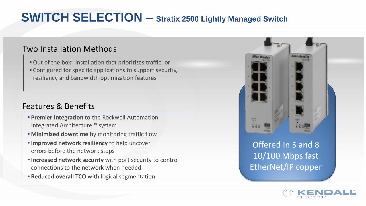
SWITCH SELECTION – Stratix 2500 Lightly Managed Switch
Two Installation Methods
• Out of the box” installation that prioritizes traffic, or• Configured for specific applications to support security,
resiliency and bandwidth optimization features
• Premier Integration to the Rockwell Automation Integrated Architecture ® system
• Minimized downtime by monitoring traffic flow
• Improved network resiliency to help uncover errors before the network stops
• Increased network security with port security to control connections to the network when needed
• Reduced overall TCO with logical segmentation
Features & Benefits
Offered in 5 and 8 10/100 Mbps fast
EtherNet/IP copper
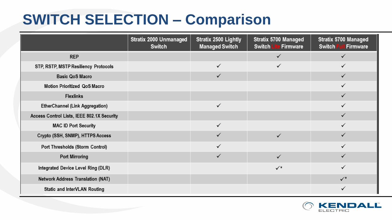
SWITCH SELECTION – Comparison
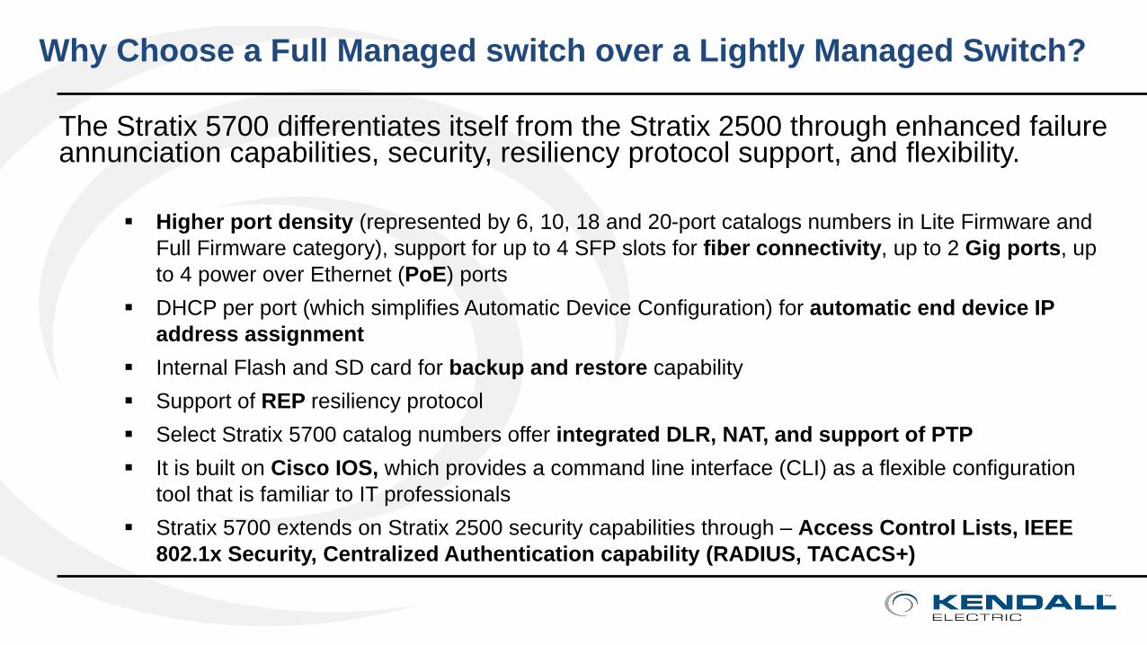
The Stratix 5700 differentiates itself from the Stratix 2500 through enhanced failure annunciation capabilities, security, resiliency protocol support, and flexibility.
Higher port density (represented by 6, 10, 18 and 20-port catalogs numbers in Lite Firmware and
Full Firmware category), support for up to 4 SFP slots for fiber connectivity, up to 2 Gig ports, up
to 4 power over Ethernet (PoE) ports
DHCP per port (which simplifies Automatic Device Configuration) for automatic end device IP
address assignment
Internal Flash and SD card for backup and restore capability
Support of REP resiliency protocol
Select Stratix 5700 catalog numbers offer integrated DLR, NAT, and support of PTP
It is built on Cisco IOS, which provides a command line interface (CLI) as a flexible configuration
tool that is familiar to IT professionals
Stratix 5700 extends on Stratix 2500 security capabilities through – Access Control Lists, IEEE
802.1x Security, Centralized Authentication capability (RADIUS, TACACS+)
Why Choose a Full Managed switch over a Lightly Managed Switch?
Practical Solutions & Connected Enterprise
• SWITCH SELECTION – Managed vs. UnManaged
• OUT OF THE BOX – Stratix 2500 Express Setup
• PHYSICAL LAYER – Structured Cabling and CPwE Best Practices
• LOGICAL LAYER – VLANs, NAT & ROUTING
• TOOLS & RESOURCES
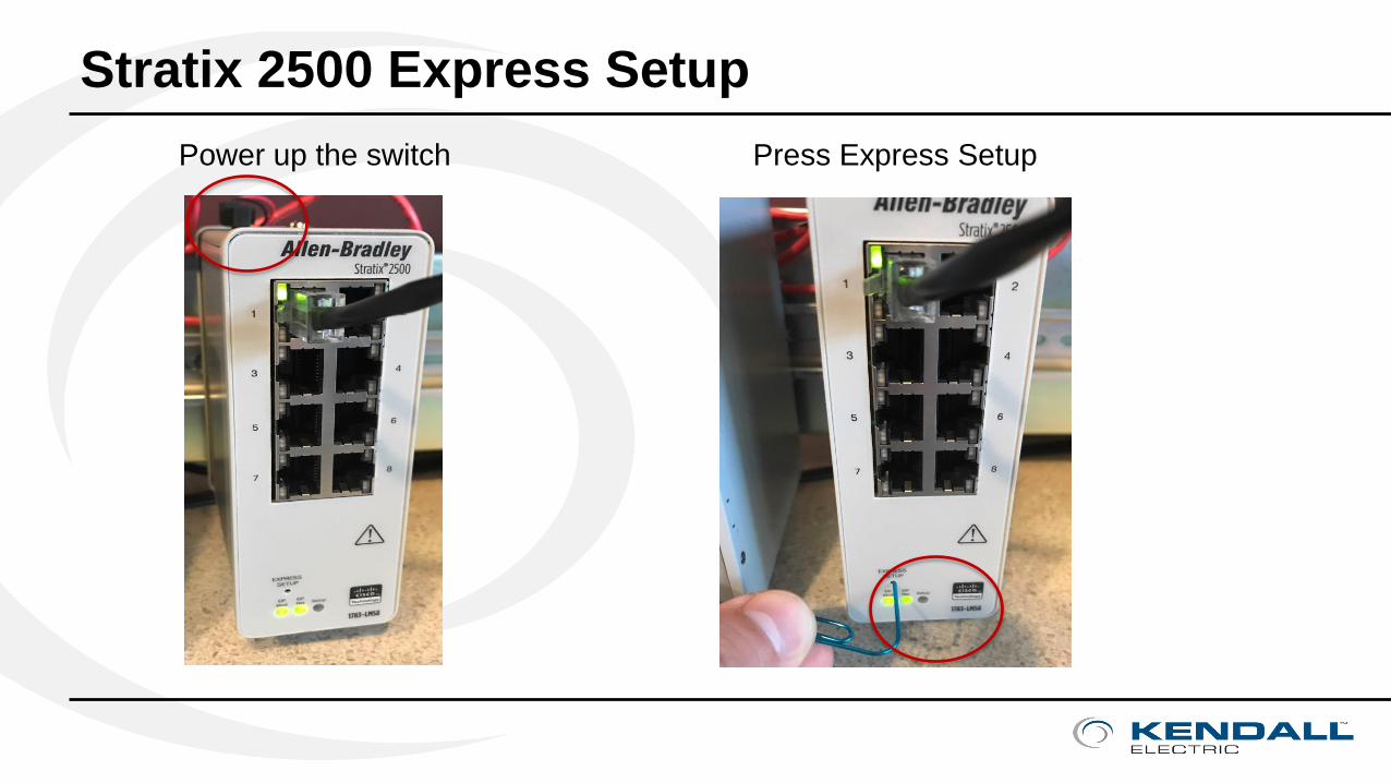
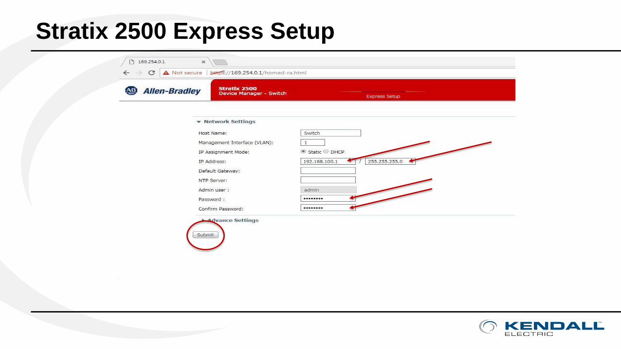
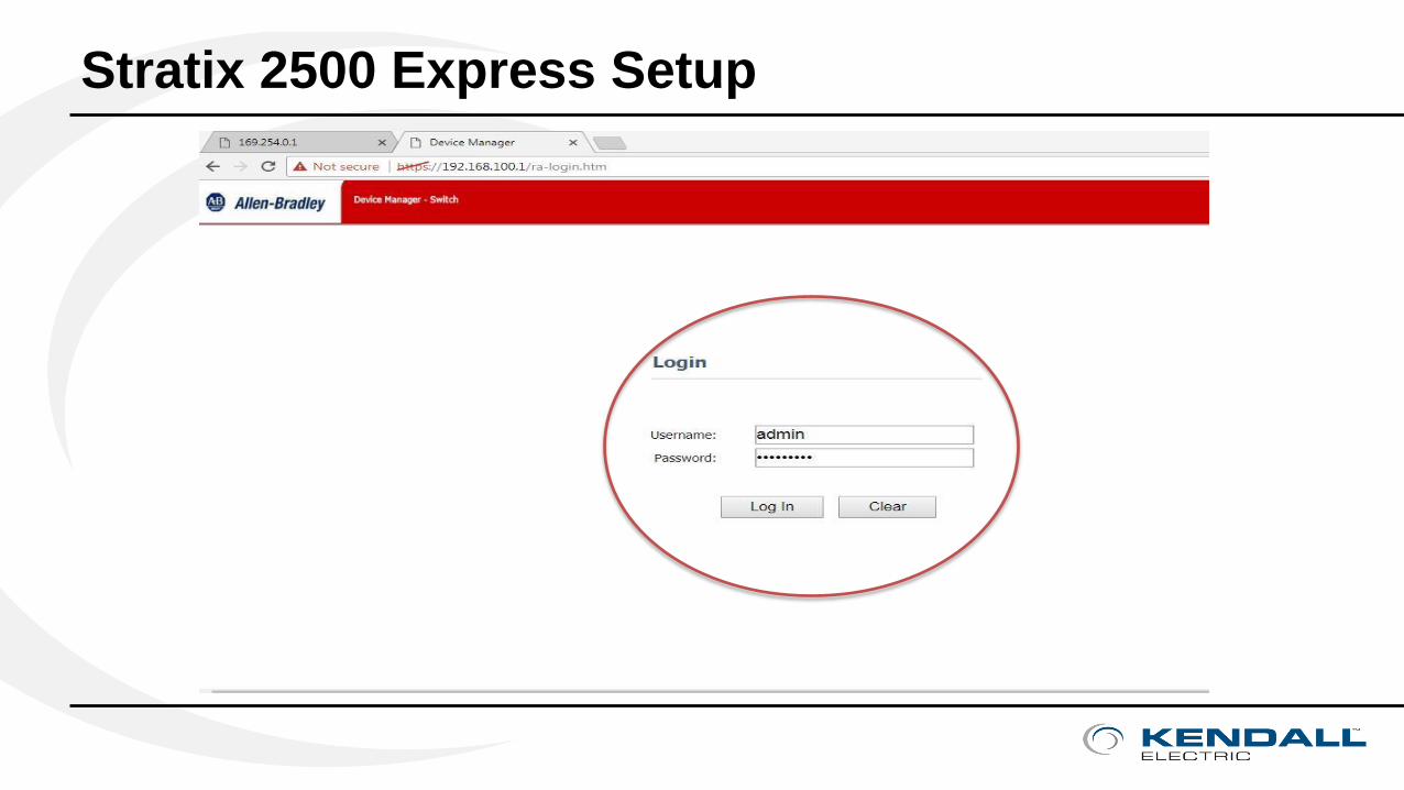
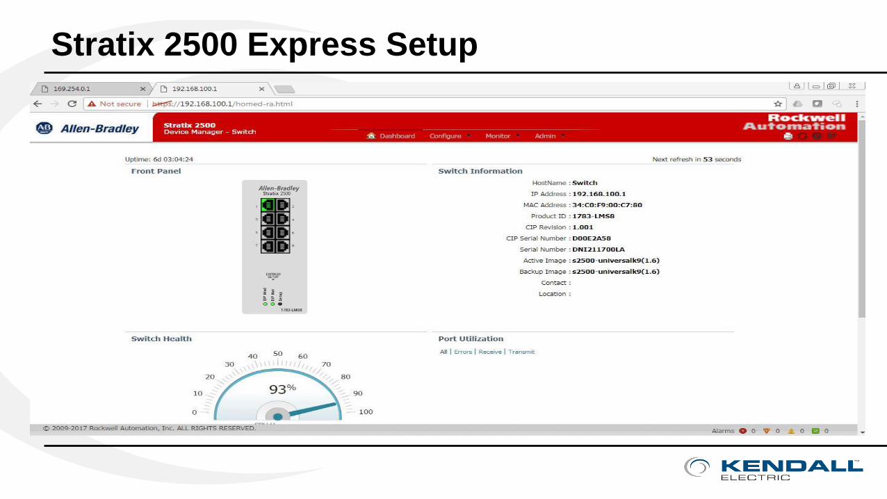
Stratix 2500 Express Setup
Power up the switch Press Express Setup

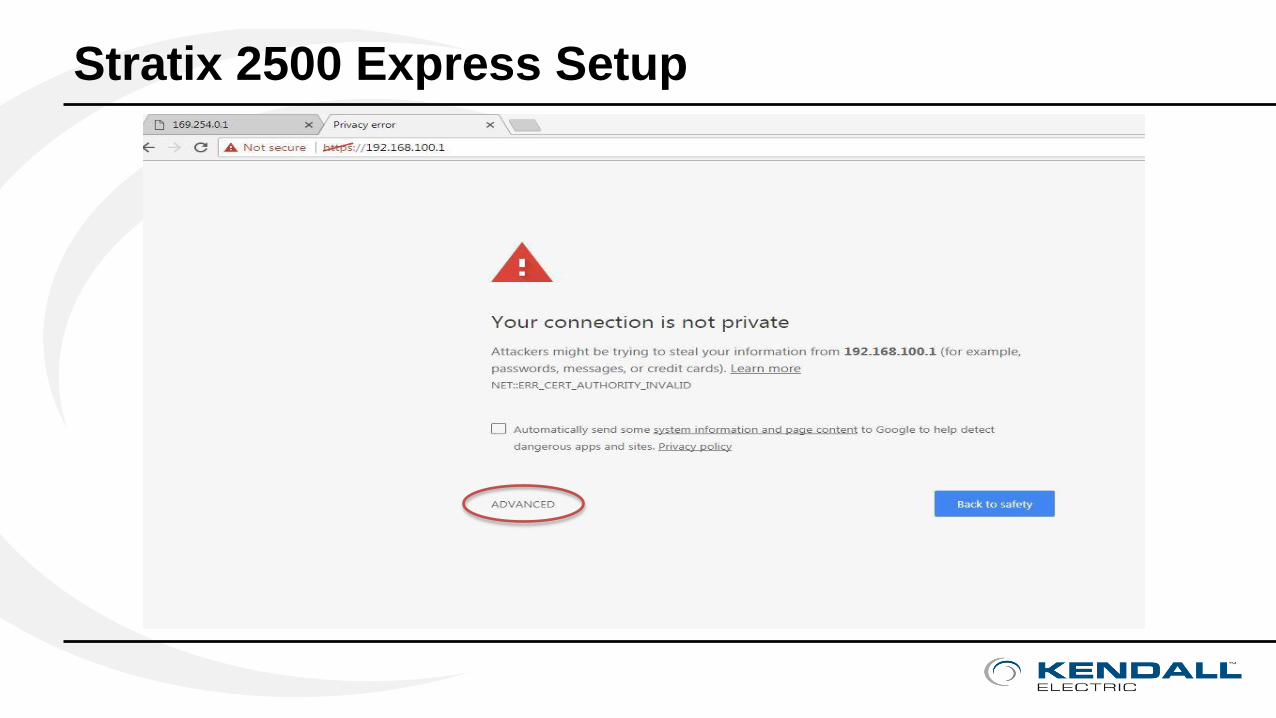
Stratix 2500 Express Setup
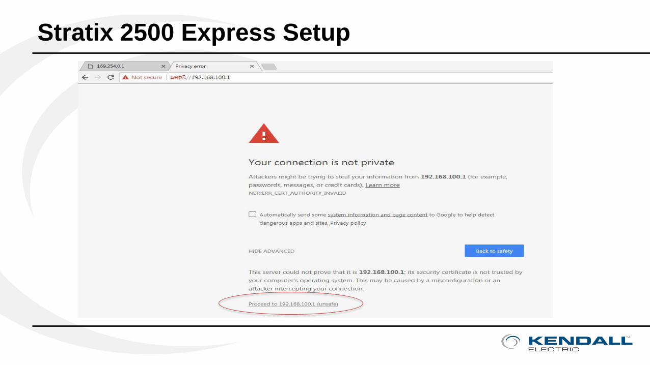
Stratix 2500 Express Setup
Stratix 2500 Express Setup
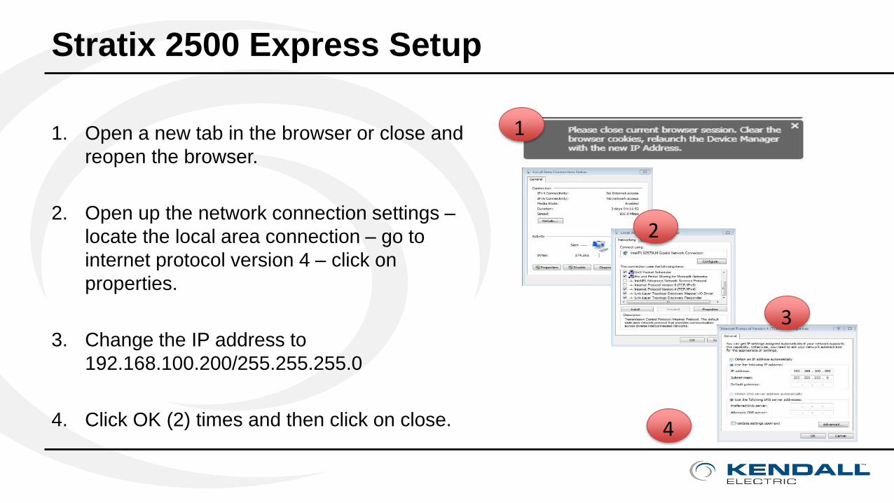
1. Open a new tab in the browser or close and
reopen the browser.
2. Open up the network connection settings –
locate the local area connection – go to
internet protocol version 4 – click on
properties.
3. Change the IP address to
192.168.100.200/255.255.255.0
4. Click OK (2) times and then click on close.
1
2
3
4

Stratix 2500 Express Setup
• Open a command window and test the connection between the switch and your pc.
Ping 192.168.100.1
Stratix 2500 Express Setup
Stratix 2500 Express Setup
Stratix 2500 Express Setup
Stratix 2500 Express Setup
Stratix 2500 – DEMO
Basic Offering
SWITCH SELECTION – 5700 Series
Basic Offering
SWITCH SELECTION – ArmorStratix 5700
10-port
18-port
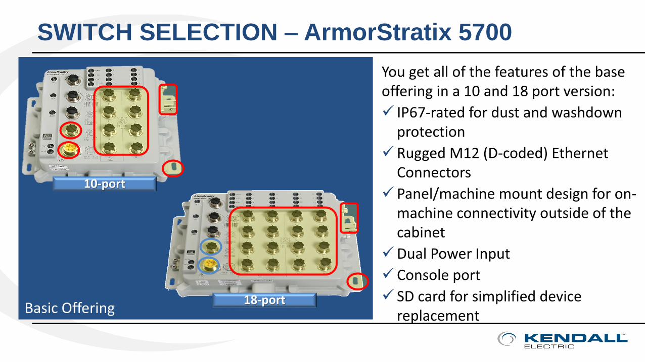
You get all of the features of the base offering in a 10 and 18 port version:
IP67-rated for dust and washdown protection
Rugged M12 (D-coded) Ethernet Connectors
Panel/machine mount design for on-machine connectivity outside of the cabinet
Dual Power Input
Console port
SD card for simplified device replacementBasic Offering
SWITCH SELECTION – ArmorStratix 5700
23
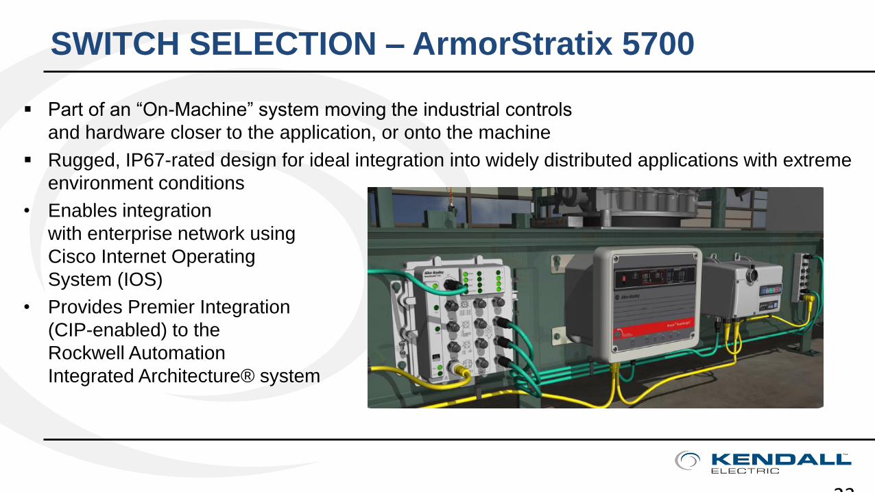
Part of an “On-Machine” system moving the industrial controls
and hardware closer to the application, or onto the machine
Rugged, IP67-rated design for ideal integration into widely distributed applications with extreme
environment conditions
• Enables integration
with enterprise network using
Cisco Internet Operating
System (IOS)
• Provides Premier Integration
(CIP-enabled) to the
Rockwell Automation
Integrated Architecture® system

Stratix 5700 Industrial Managed Switch
The Stratix 5700™ is a compact, scalable Layer 2 managed switch for use in applications from small isolated, to complex networks. The switch combines advanced Cisco technology and premier integration into the Integrated Architecture® to provide solutions for both Information Technology (IT) and Operations Technology (OT) professionals
Stratix 5700 Managed Switch Benefits
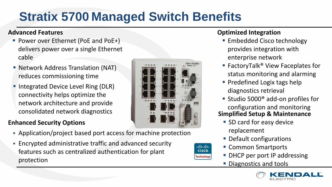
Simplified Setup & Maintenance SD card for easy device
replacement Default configurations Common Smartports DHCP per port IP addressing Diagnostics and tools
Optimized Integration Embedded Cisco technology
provides integration with enterprise network
FactoryTalk® View Faceplates for status monitoring and alarming
Predefined Logix tags help diagnostics retrieval
Studio 5000® add-on profiles for configuration and monitoring
Advanced Features Power over Ethernet (PoE and PoE+)
delivers power over a single Ethernet cable
Network Address Translation (NAT) reduces commissioning time
Integrated Device Level Ring (DLR) connectivity helps optimize the network architecture and provide consolidated network diagnostics
Enhanced Security Options
Application/project based port access for machine protection
Encrypted administrative traffic and advanced security features such as centralized authentication for plant protection
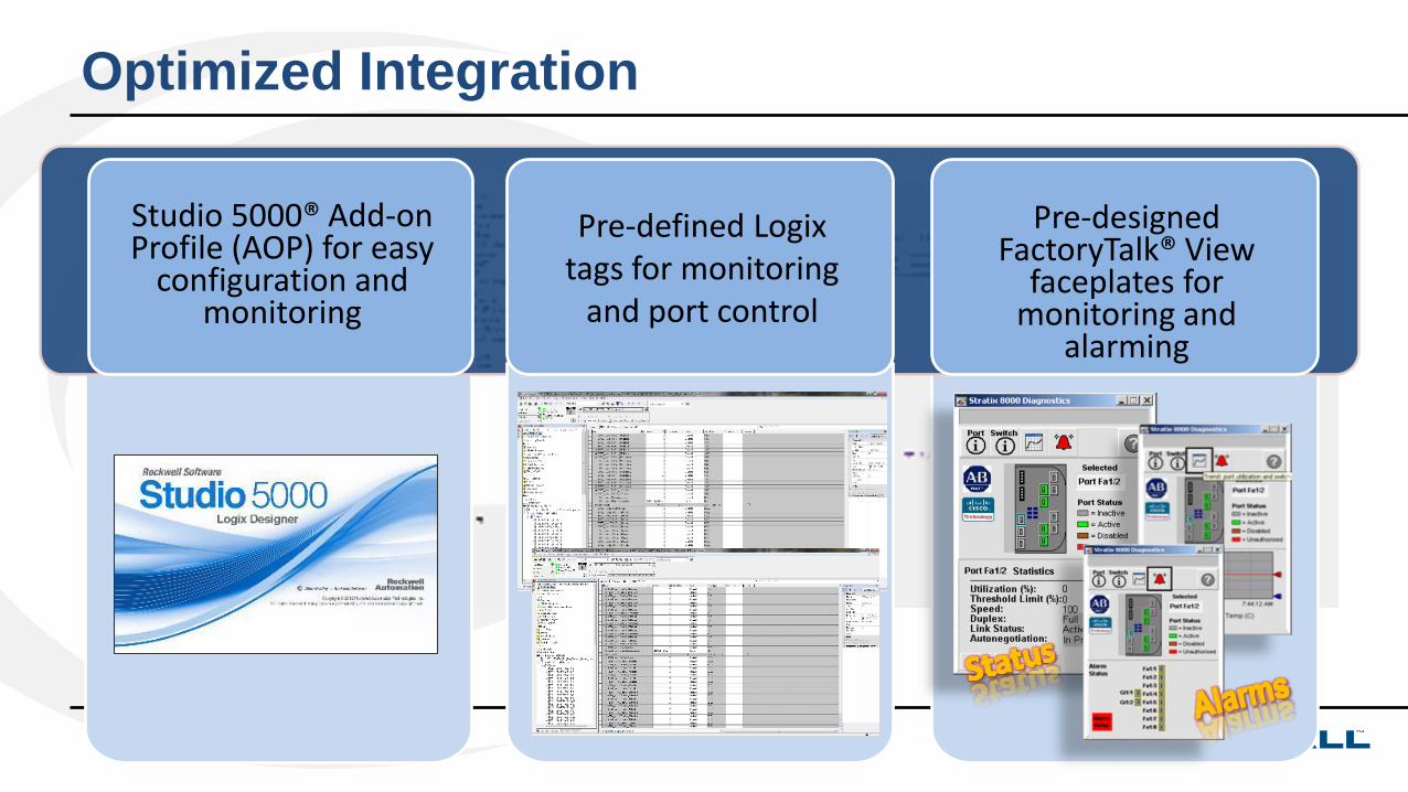
Optimized Integration
Studio 5000® Add-on Profile (AOP) for easy
configuration and monitoring
Pre-designed FactoryTalk® View
faceplates for monitoring and
alarming
Pre-defined Logix tags for monitoring
and port control
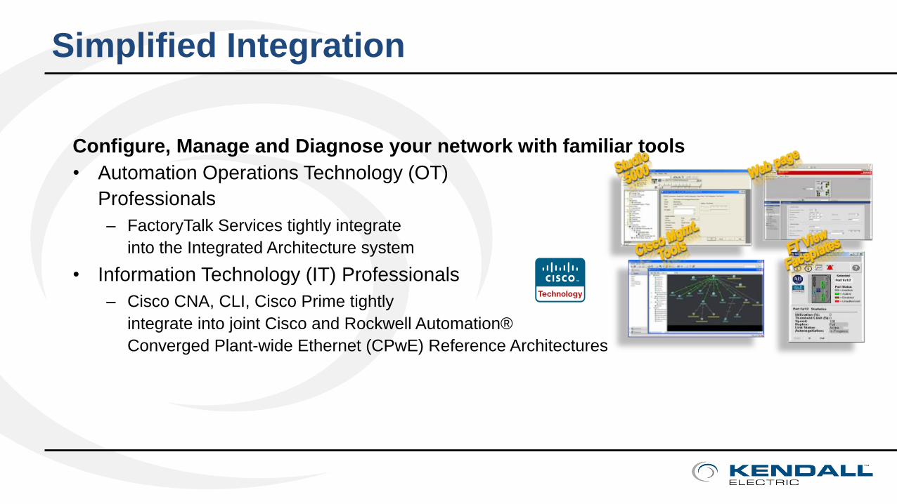
Simplified Integration
Configure, Manage and Diagnose your network with familiar tools
• Automation Operations Technology (OT)
Professionals
– FactoryTalk Services tightly integrate
into the Integrated Architecture system
• Information Technology (IT) Professionals
– Cisco CNA, CLI, Cisco Prime tightly
integrate into joint Cisco and Rockwell Automation®
Converged Plant-wide Ethernet (CPwE) Reference Architectures
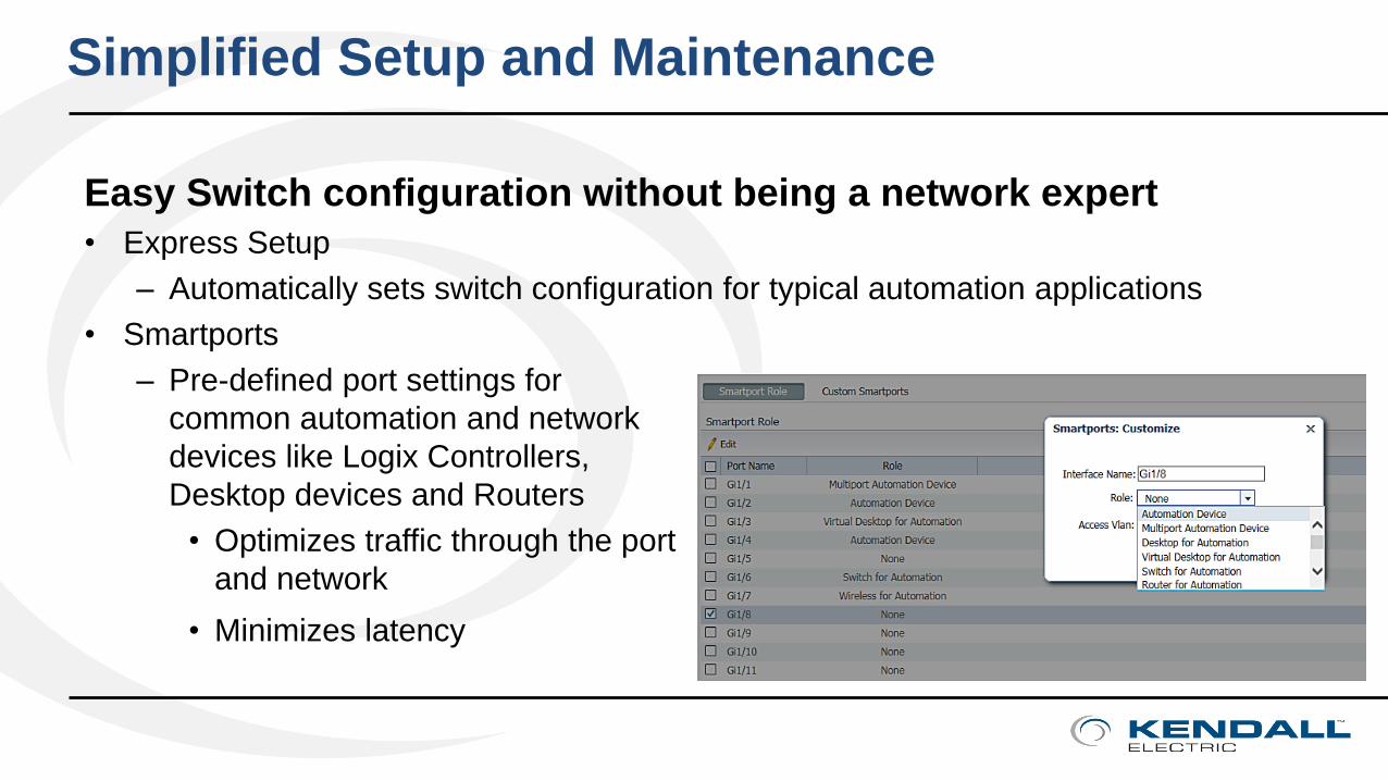
Easy Switch configuration without being a network expert
• Express Setup
– Automatically sets switch configuration for typical automation applications
• Smartports
– Pre-defined port settings for
common automation and network
devices like Logix Controllers,
Desktop devices and Routers
• Optimizes traffic through the port
and network
• Minimizes latency
Simplified Setup and Maintenance
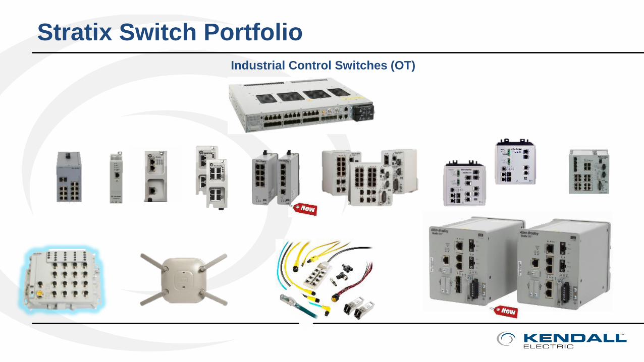
Stratix Switch Portfolio
Industrial Control Switches (OT)

Practical Solutions & Connected Enterprise
• SWITCH SELECTION – Managed vs. UnManaged
• OUT OF THE BOX – Stratix 2500 Express Setup
• PHYSICAL LAYER – Structured Cabling and CPwE Best Practices
• LOGICAL LAYER – VLANs, NAT & ROUTING
• TOOLS & RESOURCES
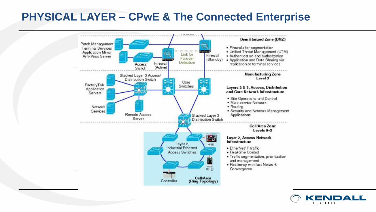
PHYSICAL LAYER – CPwE & The Connected Enterprise
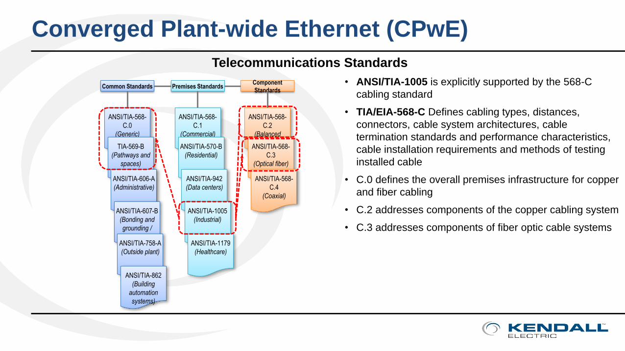
Telecommunications Standards
• ANSI/TIA-1005 is explicitly supported by the 568-C
cabling standard
• TIA/EIA-568-C Defines cabling types, distances,
connectors, cable system architectures, cable
termination standards and performance characteristics,
cable installation requirements and methods of testing
installed cable
• C.0 defines the overall premises infrastructure for copper
and fiber cabling
• C.2 addresses components of the copper cabling system
• C.3 addresses components of fiber optic cable systems
ANSI/TIA-568-
C.0
(Generic)
TIA-569-B
(Pathways and
spaces)
ANSI/TIA-606-A
(Administrative)
ANSI/TIA-607-B
(Bonding and
grounding /
earthing)ANSI/TIA-758-A
(Outside plant)
ANSI/TIA-862
(Building
automation
systems)
ANSI/TIA-568-
C.1
(Commercial)
ANSI/TIA-570-B
(Residential)
ANSI/TIA-942
(Data centers)
ANSI/TIA-1005
(Industrial)
ANSI/TIA-1179
(Healthcare)
ANSI/TIA-568-
C.2
(Balanced
twisted-pair)ANSI/TIA-568-
C.3
(Optical fiber)
ANSI/TIA-568-
C.4
(Coaxial)
Common Standards Premises StandardsComponent
Standards
Converged Plant-wide Ethernet (CPwE)

The Connected Enterprise – Micro Data Center
MDC – Micro Data CenterThe Physical Separation Between IT & OT
Cell Zone Area
IN-ROUTETM
Distributing Ethernet
Machine-to-Machine
IDF - INDUSTRIAL
DISTRIBUTION FRAMES
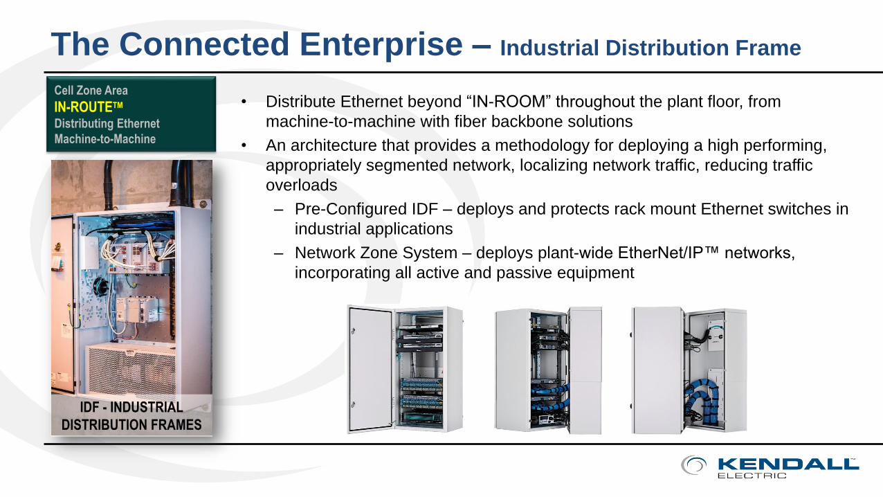
The Connected Enterprise – Industrial Distribution Frame
• Distribute Ethernet beyond “IN-ROOM” throughout the plant floor, from
machine-to-machine with fiber backbone solutions
• An architecture that provides a methodology for deploying a high performing,
appropriately segmented network, localizing network traffic, reducing traffic
overloads
– Pre-Configured IDF – deploys and protects rack mount Ethernet switches in
industrial applications
– Network Zone System – deploys plant-wide EtherNet/IP™ networks,
incorporating all active and passive equipment

Point to Point Cabling
• Single cable terminated to Jacks
• Most often stranded conductors for
flexibility
– Solid cable prone to break
– De-rated length
• Testing can be inaccurate
• Jacks can be hard to terminate reliably
for the long term, especially for higher
bandwidth cable
• Cannot plan for the future
• Distance limitations
The Connected Enterprise – Horizontal Link
Female Jack Module
Female Jack Module
Solid CoreTwisted Pair
Cable
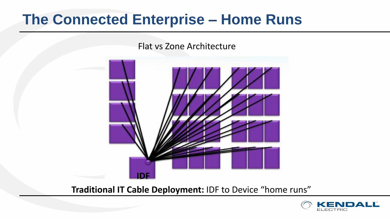
The Connected Enterprise – Home Runs
Flat vs Zone Architecture
IDF
Traditional IT Cable Deployment: IDF to Device “home runs”
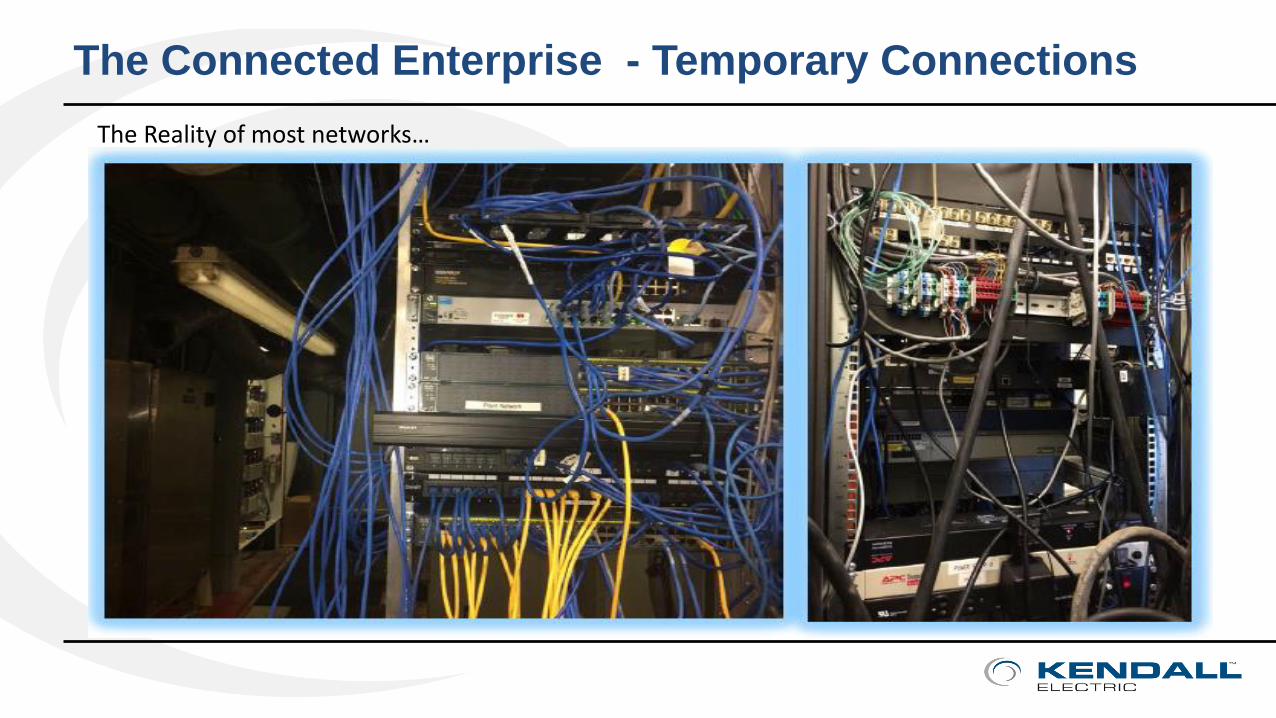
The Connected Enterprise - Temporary Connections
The Reality of most networks…
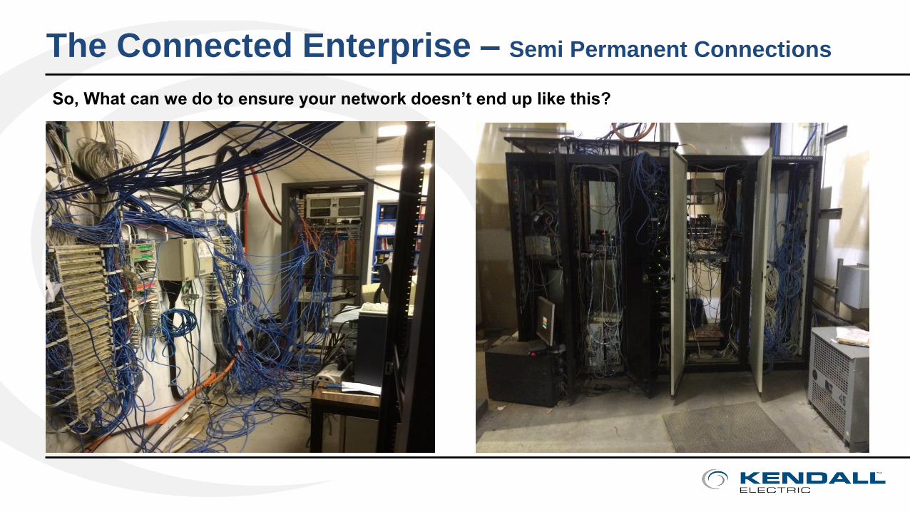
So, What can we do to ensure your network doesn’t end up like this?
The Connected Enterprise – Semi Permanent Connections

The Connected Enterprise – Zone Cabling
Flat vs Zone Architecture
IDF IDFTraditional Cable Deployment Node to network room “home runs”
Zone Architecture Reduced installation time Simplified diagnostics
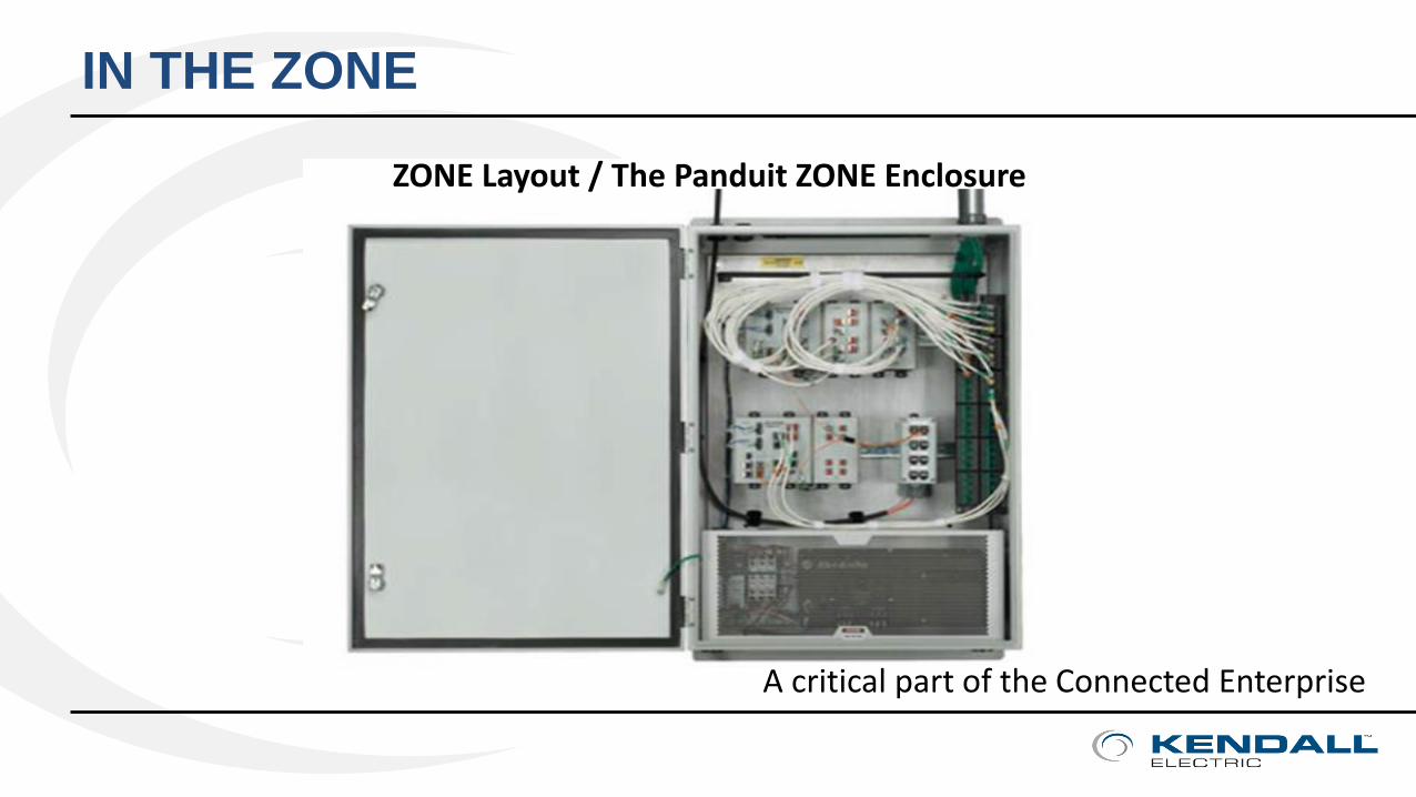
IN THE ZONE
ZONE Layout / The Panduit ZONE Enclosure
A critical part of the Connected Enterprise

The Connected Enterprise – Related Item
Other Issues You Have to Address

Practical Solutions & Connected Enterprise
• SWITCH SELECTION – Managed vs. UnManaged
• OUT OF THE BOX – Stratix 2500 Express Setup
• PHYSICAL LAYER – Structured Cabling and CPwE Best Practices
• LOGICAL LAYER – VLANs, NAT & ROUTING
• TOOLS & RESOURCES
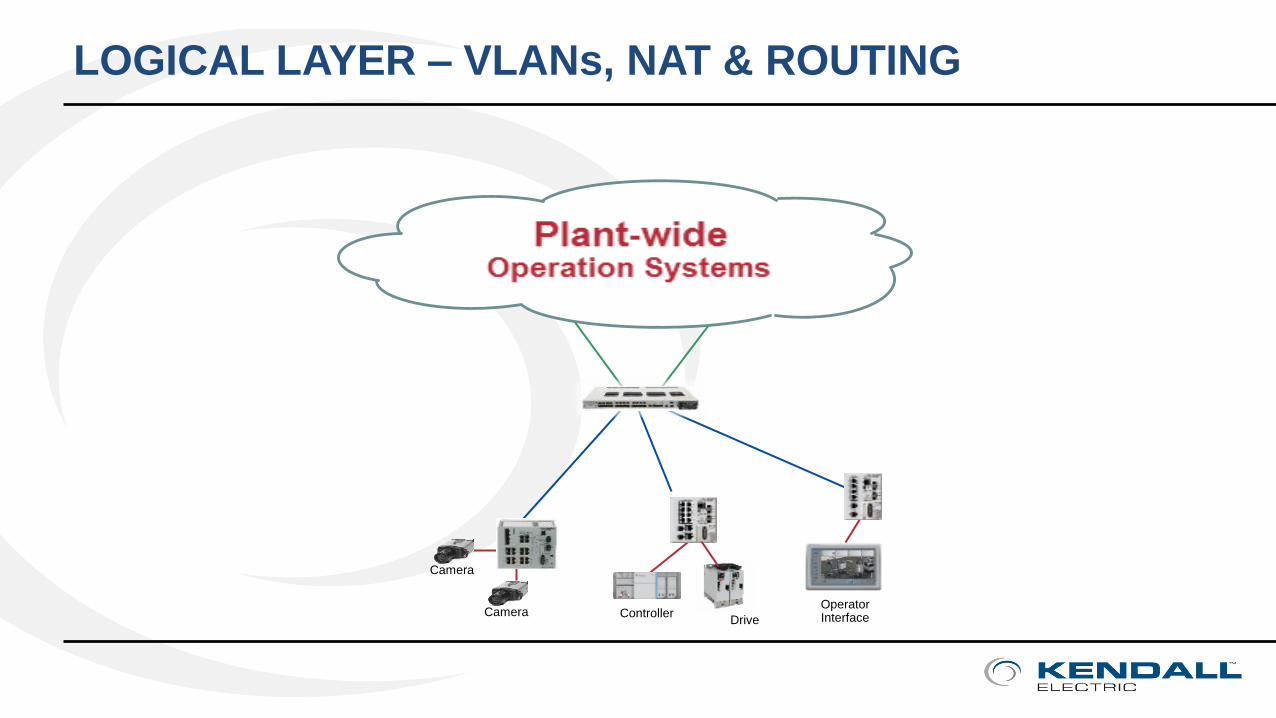
LOGICAL LAYER – VLANs, NAT & ROUTING
Operator Interface
Camera
ControllerCameraDrive
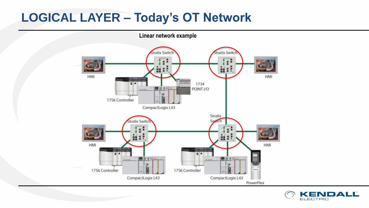
LOGICAL LAYER – Today’s OT Network
Linear network example
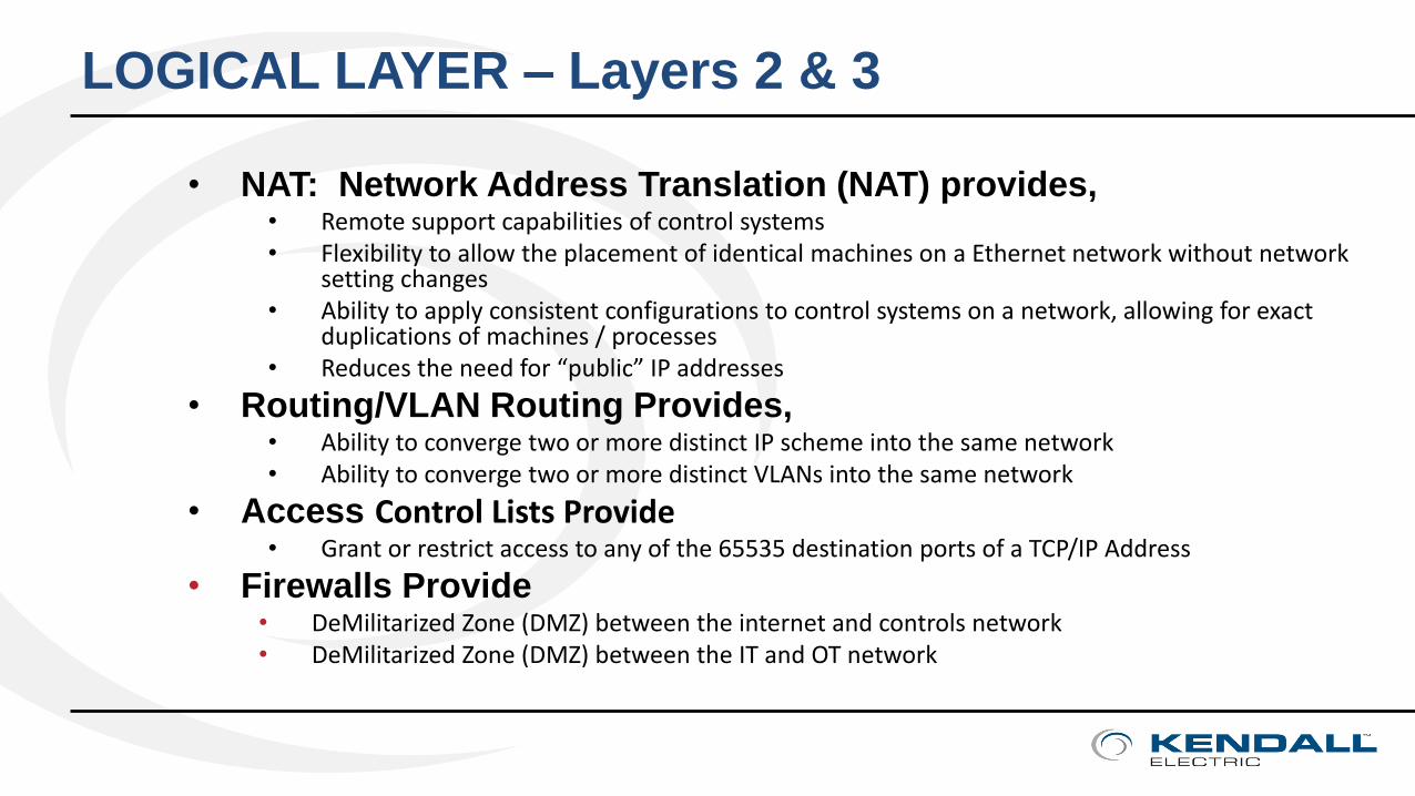
• NAT: Network Address Translation (NAT) provides, • Remote support capabilities of control systems • Flexibility to allow the placement of identical machines on a Ethernet network without network
setting changes • Ability to apply consistent configurations to control systems on a network, allowing for exact
duplications of machines / processes• Reduces the need for “public” IP addresses
• Routing/VLAN Routing Provides,• Ability to converge two or more distinct IP scheme into the same network• Ability to converge two or more distinct VLANs into the same network
• Access Control Lists Provide• Grant or restrict access to any of the 65535 destination ports of a TCP/IP Address
• Firewalls Provide• DeMilitarized Zone (DMZ) between the internet and controls network• DeMilitarized Zone (DMZ) between the IT and OT network
LOGICAL LAYER – Layers 2 & 3
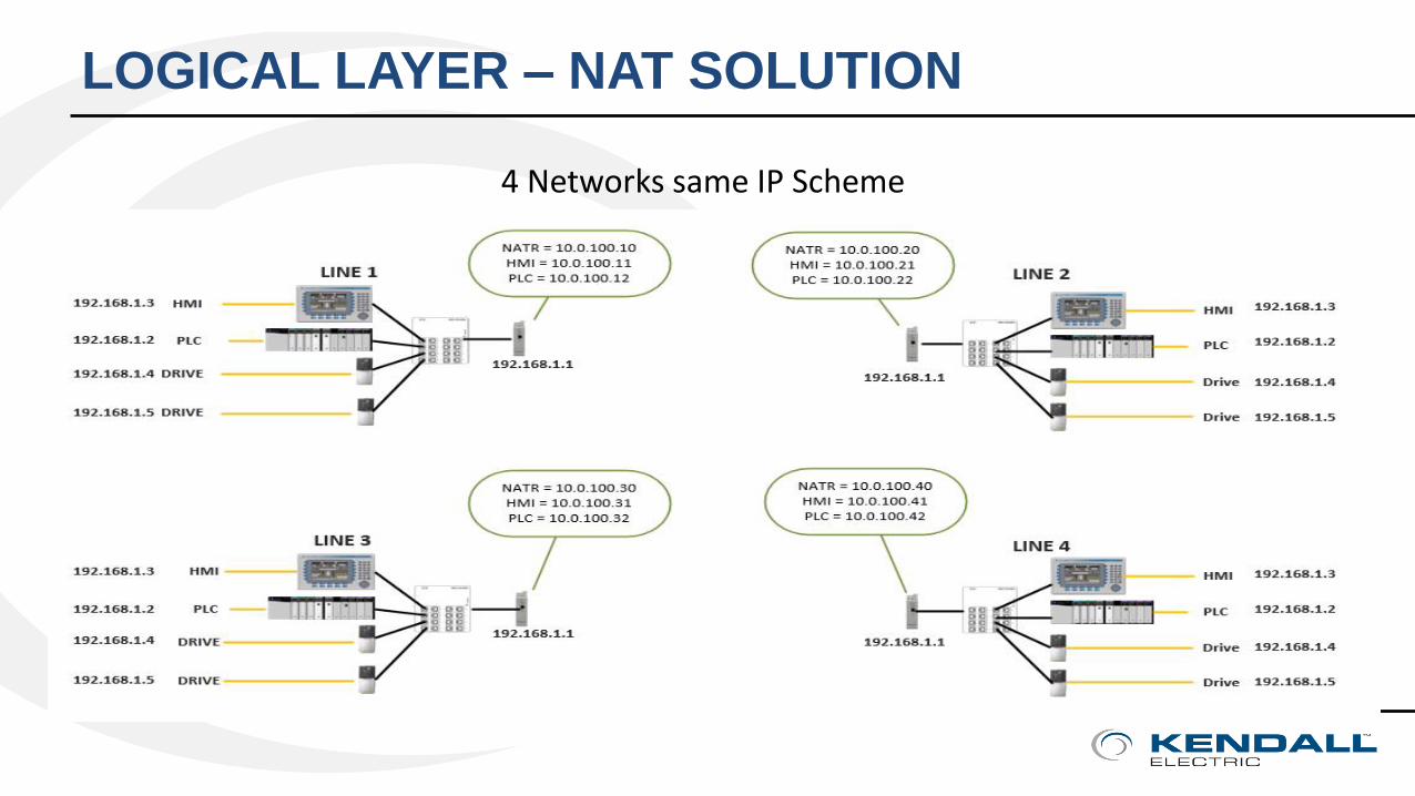
4 Networks same IP Scheme
LOGICAL LAYER – NAT SOLUTION
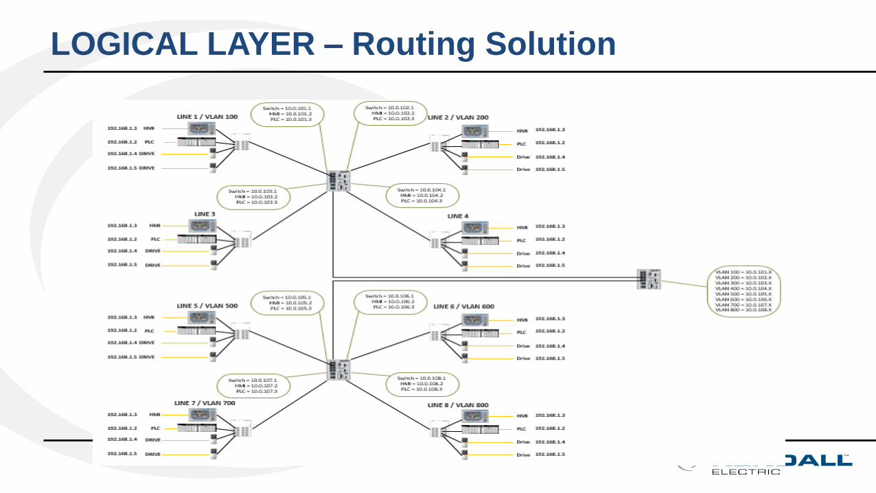
LOGICAL LAYER – Routing Solution
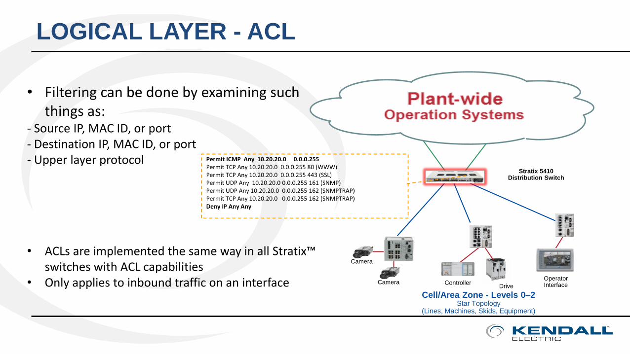
LOGICAL LAYER - ACL
Cell/Area Zone - Levels 0–2Star Topology
(Lines, Machines, Skids, Equipment)
Operator Interface
Camera
Controller
Stratix 5410 Distribution Switch
CameraDrive
• Filtering can be done by examining such things as:
- Source IP, MAC ID, or port- Destination IP, MAC ID, or port - Upper layer protocol
• ACLs are implemented the same way in all Stratix™switches with ACL capabilities
• Only applies to inbound traffic on an interface
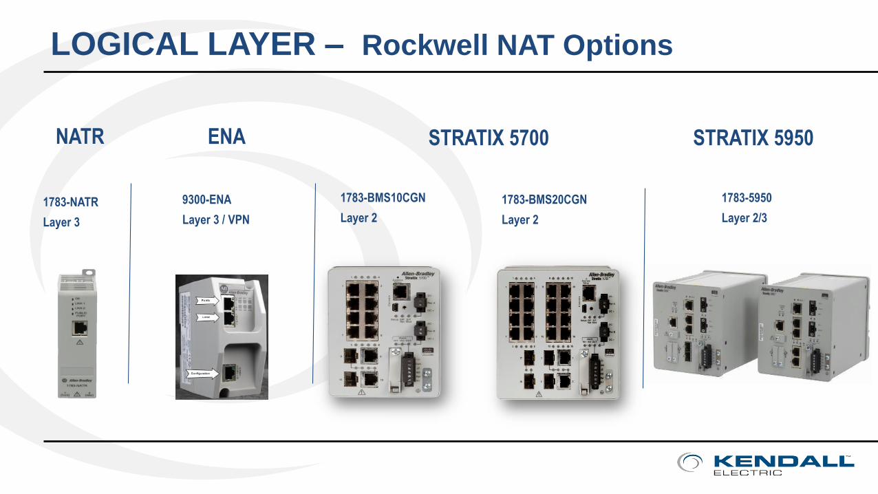
LOGICAL LAYER – Rockwell NAT Options
9300-ENA
Layer 3 / VPN
1783-BMS10CGN
Layer 2
1783-5950
Layer 2/3
1783-BMS20CGN
Layer 2
STRATIX 5700 STRATIX 5950ENANATR
1783-NATR
Layer 3

LOGICAL LAYER – Rockwell Options
5700
ENA
NATR
5950
WHEN?
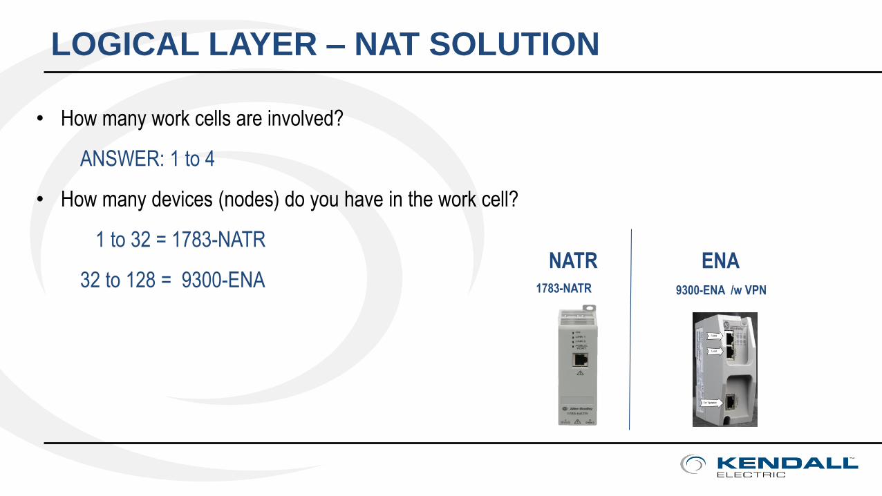
LOGICAL LAYER – NAT SOLUTION
• How many work cells are involved?
ANSWER: 1 to 4
• How many devices (nodes) do you have in the work cell?
1 to 32 = 1783-NATR
32 to 128 = 9300-ENA9300-ENA /w VPN
ENANATR1783-NATR
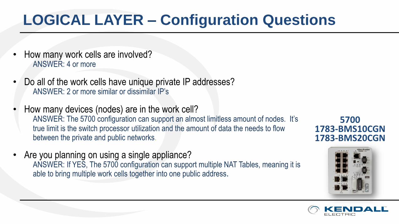
LOGICAL LAYER – Configuration Questions
• How many work cells are involved? ANSWER: 4 or more
• Do all of the work cells have unique private IP addresses? ANSWER: 2 or more similar or dissimilar IP’s
• How many devices (nodes) are in the work cell?ANSWER: The 5700 configuration can support an almost limitless amount of nodes. It’s true limit is the switch processor utilization and the amount of data the needs to flow between the private and public networks.
• Are you planning on using a single appliance?ANSWER: If YES, The 5700 configuration can support multiple NAT Tables, meaning it is able to bring multiple work cells together into one public address.
57001783-BMS10CGN1783-BMS20CGN
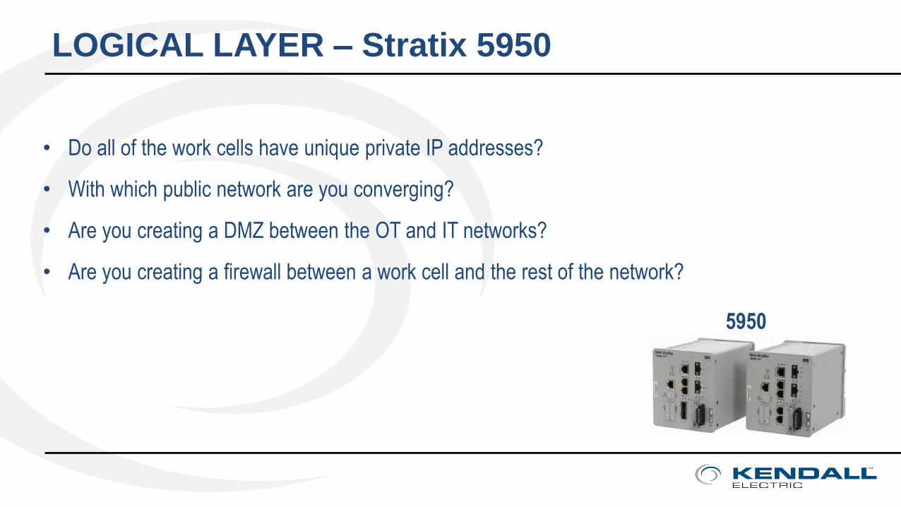
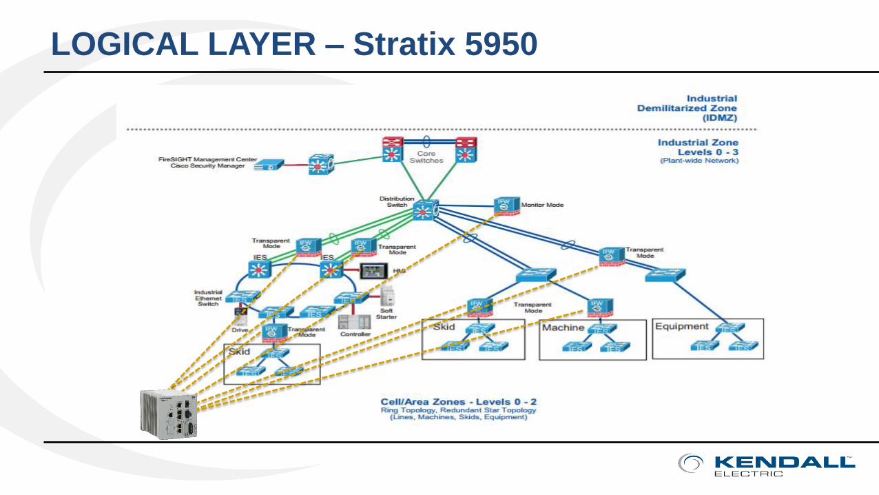
LOGICAL LAYER – Stratix 5950
• Do all of the work cells have unique private IP addresses?
• With which public network are you converging?
• Are you creating a DMZ between the OT and IT networks?
• Are you creating a firewall between a work cell and the rest of the network?
5950
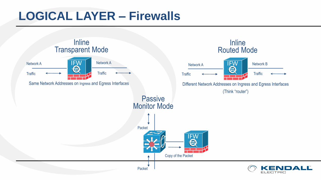
LOGICAL LAYER – Firewalls
IFW
InlineTransparent Mode
Traffic Traffic
IFW
InlineRouted Mode
Traffic Traffic
IFW
Packet
Packet
Copy of the Packet
Network A Network A
Same Network Addresses on Ingress and Egress Interfaces Different Network Addresses on Ingress and Egress Interfaces
(Think “router”)
Network A Network B
Passive Monitor Mode
LOGICAL LAYER – Stratix 5950
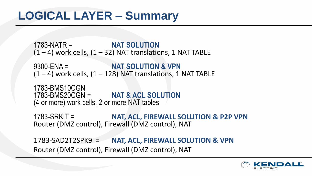
LOGICAL LAYER – Summary
1783-NATR = NAT SOLUTION(1 – 4) work cells, (1 – 32) NAT translations, 1 NAT TABLE
9300-ENA = NAT SOLUTION & VPN(1 – 4) work cells, (1 – 128) NAT translations, 1 NAT TABLE
1783-BMS10CGN1783-BMS20CGN = NAT & ACL SOLUTION(4 or more) work cells, 2 or more NAT tables
1783-SRKIT = NAT, ACL, FIREWALL SOLUTION & P2P VPNRouter (DMZ control), Firewall (DMZ control), NAT
1783-SAD2T2SPK9 = NAT, ACL, FIREWALL SOLUTION & VPNRouter (DMZ control), Firewall (DMZ control), NAT
TOOLS & RESOURCES
Join www.industrial-ip.org for the latest trends, developments, and implementation advice on the use of IP in industrial applications, don’t leave without registering.
Join www.bicsi.org for the latest ANSI/TIA Standards
Other definitions:TCP Transmission Control ProtocolUDP User Datagram Protocol

Presented by: Tom HerbstreithDatacom SpecialistMobile: [email protected]