Embed Size (px)
Citation preview

PAGE 1 Copyright Swift Engineering 2001 Release 2.4
Swift SG3 Gearbox Service Manual
Swift Engineering Inc. 1141A Via Callejon
San Clemente, CA 92673 TEL 949-492-6608 FAX 949-492-7516
[email protected] www.swiftengineering.com
Part Number SG3-Manual

PAGE 2 Release 2.4 Copyright Swift Engineering 2001
CONTENTS Page Page Illustrations 3 Powerflow Differential 11 Warning and Information Disclaimer 5 Gearbox Assembly 12 Description 5 Changing Gear Ratios 14 General Notes 6 Gear Position Indicator 15 Differential Bearing Preload 7 Reverse Gear Lockout Feature 16 Pinion Shaft Setting 8 Illustrated Parts List 18 Setting Crownwheel Backlash 9 Ratio Chart 28 Setting Barrel Alignment 10 Technical Bulletins 29

PAGE 3 Copyright Swift Engineering 2001 Release 2.4
ILLUSTRATIONS Page Page fig.1 Differential Bearing Preload 7 fig.9 Shift Barrel Details 16 fig.2 Pinion Shaft Setting 8 fig.10 Plunger Cut Off 17 fig.3 Crownwheel Backlash Setting 9 fig.11 Casing and Associated Parts 19 fig.4 Backlash Adjustment Graph 9 fig.12 Selector Assembly 20 fig.5 Setting Barrel Alignment 10 fig.13 Pinion Shaft Assembly 21 fig.6 Powerflow Differential 11 fig.14 Layshaft Assembly 22 fig.7 Selector Lever Movement 12 fig.15 Powerflow Differential Assy 23 fig.8 Gear Position Indicator Slot 15 fig.16 Special Tools 24

PAGE 4 Release 2.4 Copyright Swift Engineering 2001
WARNING
THE SWIFT PRODUCTS WHICH ARE THE SUBJECT OF THE SERVICING INSTRUCTIONS AND ILLUSTRATED PARTS LIST FOR THE SWIFT SG3 GEARBOX ARE INTENDED TO BE USED IN ULTRA-HAZARDOUS ACTIVITIES AND ARE SUBJECT TO THE FOLLOWING WARNING: (a) SWIFT PRODUCTS ARE INTENDED FOR USE IN OR AS HIGH SPEED AND HIGH PERFORMANCE RACING VEHICLES. THE RACING OF HIGH SPEED AND HIGH PERFORMANCE VEHICLES IS AN ULTRA-HAZARDOUS ACTIVITY AND INVOLVES A SUBSTANTIAL POSSIBILITY OF SERIOUS PHYSICAL INJURY OR DEATH. SWIFT PRODUCTS WILL NOT WITHSTAND ALL FORESEEABLE IMPACTS DURING THEIR NORMAL INTENDED USE IN OR AS A RACING VEHICLE WITHOUT THE SUBSTANTIAL POSSIBILITY OF SERIOUS PHYSICAL INJURY OR DEATH TO THE DRIVER OR DAMAGE TO SWIFT PRODUCTS WHICH MAY AFFECT SUCH SWIFT PRODUCT’S PERFORMANCE AND SAFE USE. (b) SWIFT PRODUCTS SHOULD ONLY BE DRIVEN OR USED (1) BY A DRIVER WITH THE REQUISITE TRAINING, SKILL AND EXPERIENCE NECESSARY FOR THE RACING OF HIGH SPEED AND HIGH PERFORMANCE VEHICLES; (2) ON SPECIALLY DESIGNED RACING TRACKS AND UNDER THE SUPERVISION OF SANCTIONED RACING ORGANIZATIONS OR OTHERWISE UNDER PROPER AND REASONABLE OPERATING CONDITIONS; AND (3) WITH PROPER MAINTENANCE AND REPAIRS TO PARTS SUBJECT TO WEAR AND TEAR, FATIGUE, OR DISINTEGRATION, AND/OR DAMAGE DUE TO COLLISION OR IMPROPER USE. INFORMATION DISCLAIMER The information and/or graphics presented in the Swift SG3 Gearbox Service Manual may include inaccuracies or typographical errors. Changes and/or improvements may also be made to the information presented herein without notice at any time. Swift Engineering Inc. makes no representations about the suitability, reliability, availability, timeliness or accuracy of the information and/or graphics presented herein. All such information and/or graphics are provided "AS IS" without warranty, representation or guaranty of any kind, express or implied. Swift Engineering Inc. hereby disclaims all warranties and conditions with regard to this information and/or graphics, including all implied warranties and conditions of merchantability, fitness for a particular purpose, and workmanlike effort. The user of the information and/or graphics contained in the Swift SG3 Gearbox Service Manual is solely responsible for its use. If the user is dissatisfied with any of such information and/or graphics, or with the terms of use, the user's sole and exclusive remedy is to discontinue using the information and/or graphics. In no event shall Swift Engineering Inc. be liable for any direct, indirect, incidental, special, consequential damages whatsoever, including, without limitation, damages for accident, injury, property damage, loss of use, loss of data or loss of profits, arising out of or in any way connected (i) with the use or performance of the information and/or graphics presented in the Swift SG3 Gearbox Service Manual , (ii) with any inability to use such information and/or graphics, or (iii) with any other use of such information and/or graphics, whether such damages are based on contract, tort, negligence, strict liability or otherwise, even if Swift Engineering Inc. has been advised of the possibility of damages.

PAGE 5 Copyright Swift Engineering 2001 Release 2.4
DESCRIPTION The SG3 gearbox is a transaxle unit, designed for mid-engined, rear wheel drive cars. The unit is produced with five forward gears, reverse, and a powerflow differential. The gear selection mechanism is sequential, with a separate mechanically actuated reverse / neutral lockout mechanism. The gear selection order is Rev - Neutral - 1st 2nd 3rd 4th 5th. The SG3 gearbox has built in selectable shaft locking to facilitate tightening of the shaft nuts. Therefore it is imperative that the re-verse lockout plunger is always fitted before using the gearbox. The drive is taken from the engine via the clutch shaft, which turns input and pinion gears to drive the final drive and differential. Gear changing is effected through non-synchronising face dogs. An extensive range of gear ratios provides a wide range of gearing permutations. The gear ratios and differential assembly can easily be changed without removing the gearbox from the vehicle. Heat treated nickel chrome steel is used to manufacture all gears and shafts. The selector forks are also steel. The gearbox has an extensive lubrication system via an internal gear type pump. In general configuration, the SG3 gearbox is a high tech racing transaxle unit which achieves the maximum effective use of power in conjunction with extremely stiff integral rear suspension and wing mountings.
Weight 88 lbs (40 Kg) Final drive ratio 9/34
Oil type SAE 80 or 90 Clutch shaft Made to customer's requirements
Oil quantity 2.65 US pints (1.25 litres) Pinion shaft nut tightening torque 120 lbs.ft. (160 Nm)
Oil qty (with oil cooler) 3.12 US pints (1.48 litres) Pinion bearing nut tightening torque 150 lbs.-ft. (205 Nm)
Max. torque 195 lbs.-ft (265 Nm) Layshaft nut tightening torque 80 lbs.-ft. (110 Nm)
Max. power 300 Hp Crownwheel bolt tightening torque 75 lbs.-ft. (100 Nm)
TECHNICAL SPECIFICATIONS

PAGE 6 Release 2.4 Copyright Swift Engineering 2001
GENERAL NOTES 1. Read these instructions carefully and with reference to the illustrations. 2. Before dismantling the gearbox, see that a clean tray is available, in which to place the parts. 3. Thoroughly clean and inspect all parts before reassembly. Discard any worn or damaged components and replace with new
ones. 4. Use only genuine Swift parts as replacements. These are manufactured to the fine tolerances necessary and are rigorously
inspected. 5. Always ensure that locknuts, locking washers, and oil seals are in good condition when reassembling. 6. All studs and screws must be secured using a threadlocking adhesive or wirelocked in position, unless stated otherwise. 7. Bearing Replacement : Bearings can only be removed or installed if the casings have been warmed in an oven or with a
torch. In the latter case, keep the torch moving while heating the casing. Use caution not to overheat the case. Test with a spot of water which will bounce off at the correct temperature or use a temperature crayon (approx 120ºC/250ºF). Once the case is heated, all bearings should be pressed into their respective seatings without delay, thus eliminating the need to reheat. At the correct temperature, fitting the bearings should present no difficulty. Ensure that the layshaft front bearing has the anti-rotation hole aligned with the screw hole. When the case has cooled lightly press the bearings to ensure that they are correctly seated.
8. Oil: Fill the gearbox through the plug hole on top of the maincase. The oil will find it's own level within the gearbox. Too much
oil will not directly cause any harm, but is undesirable as it may induce power loss and overheating of internals.

PAGE 7 Copyright Swift Engineering 2001 Release 2.4
fig. 1
PART No. RATIO MOUNTING DISTANCE
ITEM # (23) ITEM # (23)
SG3-221-9/34 9/34 1.800” SG3-FT-205-2A SG3-FT-205-2A
DIFFERENTIAL BEARING PRELOAD Requires special tool SG3-SK-119 (2 Required) Assemble the differential case (86) and end cap (86.2), and bolt the crownwheel (88.2) to it. Fit the differential unit into the maincase (72) using dummy bearings SG3-SK-119 and fit the sideplate (74). Adjust the shims (24) if necessary, to achieve .007”/.009” preload across the bearings.
Shim (24) SG3-FT-206-1
Shim (24) SG3-FT-206-1
Dummy Bearing SG3-SK-119
Dummy Bearing SG3-SK-119

PAGE 8 Release 2.4 Copyright Swift Engineering 2001
PINION SHAFT SETTING Requires special tool SG3-SK-1722
Press the pinion head bearing assembly (35) onto the pinion shaft (88.1). Heat the maincase in the area of the pinion bearing (use a metal heat shield to prevent overheating of the selector components) and insert the pinion shaft with its bearing assembly and a .010” shim (37) into the maincase. Install the pinion bearing washer (38) and nut (36) and tighten to the specified torque. Slide hubs (29, 89), bearing inner tracks (27, 28), washers (90, 91) and the pinion tail bearing (4) inner race onto the pinion shaft and install and torque the pinion shaft nut (146) to the specified torque using socket SG3-SK-962. Fit tool SG3-SK-1722 into the maincase differential bearing bore, and use feeler gauges to measure the gap between the tool and the pinion front face. This clearance should comply with the dimension indicated on the pinion shaft label (also stamped on the front face of the pinion shaft), and can be adjusted by adding or removing shims (37) from behind the pinion head bearing housing (35). Important Note: It is imperative to check the selector barrel setting after changing / resetting a pinion shaft or pinion head bearing.
fig. 2
Tool SG3-SK-1722 Nut
Shim
Measure Setting Distance with Feeler Gauges.

PAGE 9 Copyright Swift Engineering 2001 Release 2.4
SETTING CROWNWHEEL BACKLASH With the pinion shaft correctly fitted and the correct crownwheel bearing shims ascertained, the actual backlash can be measured by means of a dial indicator against the crownwheel tooth flank (fig 3a & 3b). Be sure to take at least 6 backlash readings, turning the crownwheel 30-45 degrees between each reading to account for any variation due to manufacturing tolerances. Using this method the minimum backlash should be .005” (.127mm). If the measured backlash is incorrect, remove the appropriate thickness of shims (24) from behind one differential bearing and insert them behind the other differential bearing, thus moving the differential laterally in the maincase. Do not add or discard any shims at this stage as to do so would affect the differential bearing preload. Once the correct backlash has been achieved, replace the dummy differential bearings with bearings (22) and confirm that the backlash is still correct. Note: Dummy bearings are used so that it is easy to change the shims during the setting procedure. Before fitting the actual differential bearings it is important to compare their width with that of the dummy bearings and compensate the shims accordingly for any difference.
fig. 3a
BACKLASH ADJUSTMENT 9/34 RATIO
0
0.002
0.004
0.006
0.008
0.01
0.012
0.014
0.016
0.00
50
0.00
55
0.00
60
0.00
70
0.00
75
0.00
80
0.00
90
0.01
00
0.01
10
0.01
15
0.01
20
0.01
30
0.01
40
0.01
45
0.01
50
0.01
60
MEASURED BACKLASH
RED
UC
E SH
IM B
Y
fig. 3b
fig. 4

PAGE 10 Release 2.4 Copyright Swift Engineering 2001
SETTING BARREL ALIGNMENT - Requires special tool No.SG3-SK-1721 1. Place the roller (5) onto the detent plunger (2), and insert them into the bearing carrier (71). Slide the bearing retaining plate
(77) into position and insert the screws (63).
2. Assemble the spacers (106,107), springs (119), bearing (3), barrel (99) and circlip (12) into the bearing carrier, and secure using bearing retaining plate (82) and nuts (51). Ensure that each spring is oriented so that it’s overlapping ends are not aligned with those of any other springs in the same set. It is necessary to apply about 100 lbs. force to compress the springs to enable the circlip to be fitted. This can be done by hand or in a press using an appropriately shaped mandrel.
3. Add the detent spring (1), bonded seal (129), and detent plug (81).
4. Slide the selector forks (98) over the barrel (99) and secure using selector pins (46). Use a threadlocking adhesive on the pins for final assembly.
5. Measure the depth from the rear face of the maincase to the rear face of the pinion bearing inner race. Use shims to reproduce the same measurement on the fork setting fixture from the shoulder of the dummy shaft to the ends of the spacer bars.
6. Stack the pinion gears (115.1,116,117), hubs (29,89), bearing tracks (27,28), clutch rings (93), reverse sliding gear (92) and spacers (90,91) in place in the bearing carrier and slide the assembly onto the dummy pinion shaft of the fork setting fixture.
7. Torque the pinion shaft nut (146) onto the end of the dummy pinion shaft.
8. Rotate the barrel to the neutral position. Measure and record the gap between the dogfaces of first and fifth gears. First, third and fifth gear dog gap measurements will be similar as will second and fourth. Any difference between the odd and even gear measurements must be adjusted by changing the thickness of the pinion shaft spacer (91).
Note: It is not possible (or necessary) to adjust each fork individually. After setting the forks, engage each gear in turn and ensure that
there is no binding of the pinion gears against the hubs. Such binding is indicative of incorrect barrel setting or damaged parts. fig. 4
Setting Spacer
Setting Shim
Fork Setting Fixture SG3-SK-1721
fig. 5
PAGE 11 Copyright Swift Engineering 2001 Release 2.4
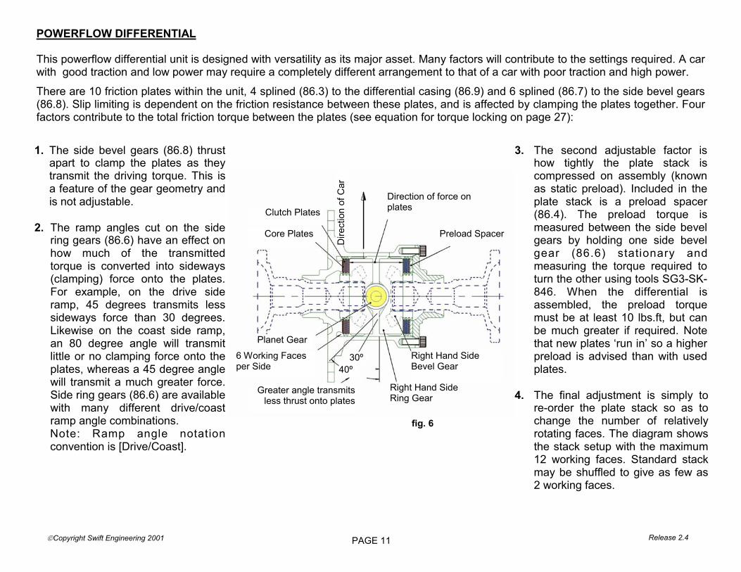
fig. 6
POWERFLOW DIFFERENTIAL This powerflow differential unit is designed with versatility as its major asset. Many factors will contribute to the settings required. A car with good traction and low power may require a completely different arrangement to that of a car with poor traction and high power.
There are 10 friction plates within the unit, 4 splined (86.3) to the differential casing (86.9) and 6 splined (86.7) to the side bevel gears(86.8). Slip limiting is dependent on the friction resistance between these plates, and is affected by clamping the plates together. Four factors contribute to the total friction torque between the plates (see equation for torque locking on page 27):
Clutch Plates
Core Plates
Dire
ctio
n of
Car
Planet Gear
6 Working Faces per Side
Right Hand Side Ring Gear
Right Hand Side Bevel Gear
30º 40º
Greater angle transmits less thrust onto plates
Preload Spacer
Direction of force on plates
1. The side bevel gears (86.8) thrust apart to clamp the plates as they transmit the driving torque. This is a feature of the gear geometry and is not adjustable.
2. The ramp angles cut on the side
ring gears (86.6) have an effect on how much of the transmitted torque is converted into sideways (clamping) force onto the plates. For example, on the drive side ramp, 45 degrees transmits less sideways force than 30 degrees. Likewise on the coast side ramp, an 80 degree angle will transmit little or no clamping force onto the plates, whereas a 45 degree angle will transmit a much greater force. Side ring gears (86.6) are available with many different drive/coast ramp angle combinations.
Note: Ramp angle notation convention is [Drive/Coast].
3. The second adjustable factor is how tightly the plate stack is compressed on assembly (known as static preload). Included in the plate stack is a preload spacer (86.4). The preload torque is measured between the side bevel gears by holding one side bevel gear (86.6) stationary and measuring the torque required to turn the other using tools SG3-SK-846. When the differential is assembled, the preload torque must be at least 10 lbs.ft, but can be much greater if required. Note that new plates ‘run in’ so a higher preload is advised than with used plates.
4. The final adjustment is simply to
re-order the plate stack so as to change the number of relatively rotating faces. The diagram shows the stack setup with the maximum 12 working faces. Standard stack may be shuffled to give as few as 2 working faces.

PAGE 12 Release 2.4 Copyright Swift Engineering 2001
GEARBOX ASSEMBLY 1. It is assumed that all bearings, oil seals, studs, oil jets, and dowels are already fitted into casing. (see page 5). 2. Slide the rearmost tophat bush (31) into place in the maincase, then slide it rearwards as far as it will go. Push the other tophat
bush into place in the maincase. Press the bearing into the reverse idler gear (95), slide the sleeve into the bearing and position the gear between the tophat bushes with the chamfer facing aft. Apply threadlocking adhesive to the retaining bolt and tighten into place.
3. Assemble and lubricate the oil pump (113). Slide on the pump drive gear (142) and secure with circlip (127). Fit the pump in
place in the maincase and secure with screw (122). 4. Slide the crank spindle (108) into it’s bearings (9), slide on the washer (135) and fit the selector lever (112) to the crank spindle
using roll pin (33). Assemble spherical rod end pair #1 (101 & 111) and adjust to centre distance 1.75” and lock with nut (54). Attach one rod end to the clevis (102) using screw (66) and nut (51). Push the clevis into the bore in the maincase, then add the washers (130), spring (120), spacer (19), screw (65), and plug (78) from the outside of the maincase. Attach the lower rod end to the crank (108) using screw (61) and washer (131).
5. Press the bearing (10) into the ratchet arm (110) bore. Sub-assemble the pawls (109) and spring (137). Fit the pawls into the
ratchet arm (110), and secure with screws (70) and nuts (51). Assemble spherical rod end pair #2 (101 & 111) and adjust to centre distance 2.00” (with rod end axes at 90°) & lock with nut (54). Secure one of the rod ends to the ratchet arm using screw (61). Fit the tophat spacer (104) into the maincase. At this point it is useful to wedge the pawls in their fully disengaged position by inserting a piece of sheet metal (approx 1.25” wide) between them, adjacent to the spring. Hold the ratchet arm in position in the maincase, then fit the spindle (103) and secure with screw (67). Attach the lower rod end to the crank spindle (108) using screw (61) and washer (131). Insert the barrel driver into the maincase, through the ratchet arm (take care not to trap the pawls) and secure into the bearing with nut (40). Add the bearing retaining plate (49) and screws (45). Remove the sheet metal tool from between the pawls to allow them to engage the barrel driver.
6. It is important that the backlash between the barrel driver and the pawls be equal
in both upshift and downshift directions. Ensure that the barrel (99) and barrel driver (100) ‘D’ drives are indexed similarly, then temporarily fit the barrel and bearing carrier (71) onto the maincase. Restrain the barrel from rotating by fitting a temporary dowel in place of the detent spring and lightly screwing the detent cap down onto it. Measure the movement of the selector lever (fig. 7) in both
fig. 7

PAGE 13 Copyright Swift Engineering 2001 Release 2.4
upshift and downshift directions. If the movement is not equal in both directions it can be adjusted by lengthening or shortening rod end pair #1.
7. Add the reverse lock plunger (84), ‘o’ring (56), spring (121), and cap (85). Note: When inserting the gear cluster, ensure that
the barrel is in the neutral position or that the reverse lock plunger is lifted to avoid damaging either. 8. Oil the pinion head bearing, and fit the pinion shaft and pinion head bearing assembly as described on page 8. 9. Fit the clutch shaft bearing (8), seal (26) and circlip (15) into the clutch shaft bearing housing (97). Slide the bearing assembly
over the clutch shaft (96) and secure with circlip (14). Fit a wire clip (11) onto the clutch shaft, slide on the oil pump driver gear (143) and add the second wire clip (11). The second wire clip is only fitted to hold the pump gear in position when changing ratios. It serves no purpose when the gearbox is fully assembled. Slide the clutch shaft assembly into the maincase and secure with screws (45) and washers (132).
10. Adjust the differential bearing preload (see page 7) and the crownwheel backlash (page 9). Oil the differential case taper roller
bearings and load the differential assembly through the sideplate bore. Install the sideplate and secure with nuts (50). 11. Carry out sequential barrel setting as described on page 10. 12. Build the gear cluster up onto the bearing carrier. Note that the ‘D’ drive on the barrel and driver have the flat horizontal and at
the bottom of the barrel driver when neutral is selected. Offer the whole assembly up to the maincase and slide the complete cluster into position. It may be necessary to rotate the shafts or clutch rings to help engage the pinion shaft splines.
Tighten the layshaft nut (53) to the specified torque settings (see page 5). Bend the tab washer (134) to lock the nut. Tighten the pinion shaft nut (146), fit the vernier locking ring (148) and secure with the circlip (147). Check that all gears are selectable and that the selector lever returns freely to it’s rest position after each shift.
Note: A barrel position has been provided which selects two gear simultaniously and so enables tightening of the shaft nuts by
preventing rotation of the pinion shaft. This position can be selected by upshifting from 5th gear while pulling the reverse lock plunger. FOR THIS REASON IT IS IMPERATIVE NOT TO USE THE GEARBOX WITHOUT THE REVERSE LOCK PLUNGER FITTED. It is not possible to select this barrel position without first withdrawing the reverse lock plunger.
13. Position the rear cover (73) and secure with nuts (50) Assure that the oil spray tube aft o-ring is in position before fitting the
rear cover.

PAGE 14 Release 2.4 Copyright Swift Engineering 2001
1. With a drip tray beneath the gearbox, remove the nuts (50) and remove the rear cover (73). If the cover is found to be tight or stuck, tap it gently with a soft faced mallet to break the joint. (Never attempt to force the cover off by levering between the joint faces, as this may damage the castings and result in an oil leak).
2. Pull the reverse lock and select locking position over 5th gear. This engages 1st and 5th gears together to lock the shafts. Remove the pinion and layshaft nuts (52,53) and washer (133) and loosen the layshaft.
3. Ease the bearing carrier and gear cluster assembly out of the maincase. The pinion shaft gears and hubs will need supporting as the cluster is withdrawn. This can be done by hand or by inserting tool SG3-SK-1727 through the pinion shaft tail bearing (4) .
4. Take the pinion shaft gears (116), bearings (47), hubs (29,27,28) and reverse pinion gear (92) out of the assembly. 5. Remove the layshaft nut and washer (53,134) and withdraw the layshaft (115). The input gears (116,117) may now be removed. 6. Replace the gears with the correct ratios. Gears must be exchanged in matched pairs. For identification purposes, each gear is
marked with two sets of numbers. The first of these indicates the number of teeth on the layshaft gear while the second number indicates the number of teeth on the mating pinion shaft gear. It is essential that these gears are correctly paired to as mismatching of types will result in damage or failure. For first gears, the teeth are machined integral with the layshaft. If change is required to either of these ratios both the pinion shaft gear and the layshaft itself will have to be changed.
7. While changing ratios it is advisable to wash and inspect all components which are to be refitted. Check for wear and cracks, particularly to the engagement dogs. If the corners of the engagement dogs are badly damaged, gear selection will be poor and the selector components may be damaged. If the driver has experienced any difficulty in selecting gears, check for bent selector forks, a worn or damaged barrel or a damaged fork pin. A good tip is to check the fork setting in the fixture each time the gearbox is re-assembled. A bent fork will show up as a badly set fork (unequal dog gap on each side of the relevant clutch ring).
8. Re-assembly is the reverse of the above. See page 5 for nut torque settings. Ensure that the barrel is in the neutral position before assembly into the maincase.
Note: The layshaft rear bearing inner track consists of a flanged race and a thrust ring. The thrust ring should be fitted on the forward side of the rollers to avoid the possibility of it dropping into the groove at the end of the layshaft thread.
CHANGING GEAR RATIOS

PAGE 15 Copyright Swift Engineering 2001 Release 2.4
GEAR POSITION INDICATOR The 2002 Swift Formula Atlantic car has facility to display gear position. Please read the following instructions carefully, as failure to do so may lead to the driver’s display giving incorrect gear position indication. 1. The potentiometer has a small marker
(dimple) on one end of it’s tang drive. With first gear selected, the potentiometer should be mounted on the gearbox rear cover, with the tang marker to the right side of the car and the wires exiting from the top of it’s body. If it is more convenient to have the wires exiting from the bottom of the unit, assemble the unit with the tang marker to the left side of the car.
2. Switch on the vehicle power supply to the potentiometer. This should consist of +5 volts at the brown wire and ground at the orange wire. Connect a voltmeter across the red wire and ground, and turn the potentiometer body until a reading of 0.50 ±.01 Volts is obtained (again, with neutral selected). Tighten the fixing screws in this position.
3. The Toyota ECU must be programmed to the values shown in the table opposite.
Slot in spindle with neutral selected Gear Position mVolt Threshold
Reverse 2
Neutral 705
1st 1396
2nd 2105
3rd 2871
4th 3710
5th 4714
Toyota ECU Gear Position Indicator Settings
fig. 8

PAGE 16 Release 2.4 Copyright Swift Engineering 2001
REVERSE GEAR LOCKOUT FEATURE WARNING: DO NOT UNDER ANY CIRCUMSTANCES OPERATE THE GEARBOX WITHOUT THE REVERSE GEAR LOCKOUT ASSEMBLY INSTALLED. The Swift SG3 reverse gear lockout assembly performs three functions: 1. Neutral lockout 2. Reverse gear lockout 3. Shaft Lock lockout Comments on each function follow the shift barrel description. Shift Barrel Description A full shift lever stroke is required to rotate the shift barrel to all 8 positions. There are no half-stroke positions. The complete shift barrel sequence is: Reverse, Neutral, 1st, 2nd, 3rd, 4th, 5th, Shaft Lock. The Shaft Lock position simultaneously engages 1st gear and 5th gear to allow removal and tightening of the shaft nuts during servicing. The Reverse gear and Shaft Lock positions share the same detent position, but are engaged at opposite ends of the shift barrel rotation range. The reverse gear lockout plunger rides in a dedicated track on the shift barrel with three rotation stop features: Neutral stop, Reverse gear stop, and Shaft Lock stop. 1. Neutral lockout To select Neutral from 1st gear, pull the reverse gear lockout cable to at least half stroke and hold it while pushing the shift lever forward to full stroke. The Neutral stop feature is a one way stop, allowing a Neutral-to-1st gear shift but blocking a 1st gear-to-Neutral shift. There is no danger of inadvertent selection of Reverse gear if the lockout cable is pulled to full stroke because all shifts require full travel of the gear shift lever. The Neutral lockout feature can be bypassed by removing 0.100”±0.005” [2.5mm±0.1mm] from the end of the reverse lockout plunger as
fig. 9

PAGE 17 Copyright Swift Engineering 2001 Release 2.4
illustrated in fig. 10. If this modification is performed, a 1st gear-to-Neutral shift can be performed without using the reverse gear lockout cable, but shifting to Reverse gear and Shaft Lock requires pulling the reverse gear lockout cable. 2 Reverse gear lockout To select Reverse gear from Neutral, hold the clutch pedal down, pull the reverse gear lockout cable to full stroke and hold it, then push the shift lever forward to full stroke. Do not select Reverse gear if the car is moving. To select Neutral from Reverse gear, pull the shift lever aft to full stroke. It is not necessary to pull the reverse lockout cable for this shift. 3. Shaft Lock lockout The Shaft Lock position is ONLY to be used for gearbox servicing with the car at rest and the engine off. To select Shaft Lock, upshift to 5th gear, then pull the reverse gear lockout cable to full stroke and hold it while pulling the shift lever aft. While performing these shifts, it may be necessary to rotate the differential assembly back and forth slightly to clear any dog to dog face contact. With the gearbox in the Shaft Lock position, 1st gear and 5th gear are engaged simultaneously, so the shafts cannot rotate. This allows removal and tightening of the shaft nuts. Ensure that Neutral is selected before returning the car to service. Ensure that the Reverse gear lockout cable has some slack to allow the plunger to fully seat.
fig. 10

PAGE 18 Release 2.4 Copyright Swift Engineering 2001
ILLUSTRATED PARTS LIST

PAGE 19 Copyright Swift Engineering 2001 Release 2.4
fig. 11
CASING AND ASSOCIATED PARTS

PAGE 20 Release 2.4 Copyright Swift Engineering 2001
fig. 12 SELECTOR ASSEMBLY

PAGE 21 Copyright Swift Engineering 2001 Release 2.4
fig. 13
PINION SHAFT ASSEMBLY

PAGE 22 Release 2.4 Copyright Swift Engineering 2001
fig. 14
LAYSHAFT ASSEMBLY

PAGE 23 Copyright Swift Engineering 2001 Release 2.4
fig. 15
POWERFLOW DIFFERENTIAL ASSEMBLY

PAGE 24 Release 2.4 Copyright Swift Engineering 2001
Item Qty Part # Description 1 1 SG3-102-205-11 SPRING 2 1 SG3-102-260-4 DETENT PLUNGER 3 1 SG3-BEA-037 BEARING 4 1 SG3-BEA-058 BEARING 5 1 SG3-BEA-059 BEARING 6 1 SG3-BEA-142 NEEDLE ROLLER 7 1 SG3-BEA-159 BEARING 8 1 SG3-BEA-163 BEARING 9 2 SG3-BEA-164 BEARING 10 1 SG3-BEA-165 BEARING 11 2 SG3-CIR-085 CIRCLIP 12 1 SG3-CIR-139 CIRCLIP 13 2 SG3-DG-219-1A CIRCLIP 14 1 SG3-DGB-239-0 CIRCLIP 15 1 SG3-DGB-244-10 CIRCLIP 16 1 SG3-ORI-101 O-RING 17 7 SG3-DOW-037 DOWEL 18 2 SG3-F3A-205-3 BEARING 19 4 SG3-F3D-236-1 WASHER 20 2 SG3-FGC-205-4 SEAL 21 12 SG3-FT-201-2 STUD 22 2 SG3-FT-205-1 BEARING 23 2 SG3-FT-205-2A LEFT HAND SPACER 24 3 SG3-FT-206-1 SIDEPLATE SHIM 25 1 SG3-FT-229-1 BEARING 26 1 SG3-FT-244-11 OIL SEAL 27 1 SG3-FTR-225 BEARING INNER TRACK 28 2 SG3-FTR-226 BEARING INNER TRACK 29 2 SG3-FTR-227 HUB 30 1 SG3-FTR-234-1 SPACER - INPUT SHAFT 31 2 SG3-FTR-237-1 REVERSE IDLER SPIGOT 32 1 SG3-FTR-237-2 SLEEVE 33 1 SG3-FV-252-4 ROLL PIN
34 1 SG3-HC-237-2 BEARING
Item Qty Part # Description 35 1 SG3-HC8-222-1 PINION HEAD BEARING 36 1 SG3-BEA-031 NUT 37 1 SG3-HC8-222-2 SHIM 38 1 SG3-HC8-222-2A SPACER 39 1 SG3-WSH-015 WASHER 40 1 SG3-HGL-260-10A SELECTOR BEVEL NUT 41 1 SG3-HP-M-8008 BEARING 42 4 SG3-HP-M-9015 DOWEL 43 2 SG3-HP-M-9042 DOWTY WASHER 44 2 SG3-SCR-145 SCREW 45 5 SG3-HP-N-9006 SCREW 46 3 SG3-IGT-250-1 SELECTOR FORK PIN 47 5 SG3-LD-226-1 BEARING 48 1 SG3-LIP-044 LIPSEAL 49 1 SG3-NMT-260-2 KEEP PLATE 50 19 SG3-NUT-002 NUT 51 12 SG3-NUT-019 NUT 52 1 SG3-NUT-021 NUT 53 1 SG3-NUT-022 NUT 54 2 SG3-NUT-023 NUT 55 4 SG3-ORI-001 O-RING 56 1 SG3-ORI-014 O-RING 57 1 SG3-SCR-133 SCREW 58 2 SG3-SCR-134 SCREW 59 1 SG3-SCR-012 SCREW 60 1 SG3-SCR-117 SCREW 61 3 SG3-SCR-120 SCREW 62 2 SG3-SCR-121 SCREW 63 3 SG3-SCR-122 SCREW 64 6 SG3-SCR-123 SCREW 65 1 SG3-SCR-125 SCREW 66 1 SG3-SCR-126 SCREW 67 1 SG3-SCR-127 SCREW 68 1 SG3-SCR-128 SCREW

PAGE 25 Copyright Swift Engineering 2001 Release 2.4
Item Qty Part # Description 69 1 SG3-SCR-131 SCREW 70 2 SG3-SCR-132 SCREW 71 1 SG3-0020 BEARING PLATE 72 2 SG3-0010 MAINCASE 73 1 SG3-0030 REAR COVER 74 1 SG3-0040 SIDEPLATE 75 1 SG3-201-1 OIL SPRAY PIN HD BEARING 76 1 SG3-201-2 PLUG 77 1 SG3-202-1 BEARING RETAINING PLATE 78 1 SG3-202-2 PLUG - RATCHET RETURN 79 1 SG3-202-3 BEARING RETAINING PLATE 80 1 SG3-202-4 BEARING RETAINING PLATE 81 1 SG3-202-5 DETENT PLUNGER PLUG 82 1 SG3-202-6 BEARING RETAINING PLATE 83 1 SG3-202-7 OIL SPRAY TUBE 84 1 SG3-210-35 REVERSE LOCK PLUNGER (CABLE) 85 1 SG3-210-36 REVERSE LOCK PLUG 86 1 SG3-212 DIFF ASSY
86.1 8 SG3-F3A-213-12 SCREW 86.2 1 SG3-F3A-214 END PLATE 86.3 4 SG3-FTC-213-10 CLUTCH PLATE (OUTER SPLINE) 86.4 1 SG3-FTC-213-3 SPACER 86.5 3 SG3-FTC-213-5AH PLANET BEVEL GEAR 86.6 2 SG3-FTC-213-7 SIDE GEAR RINGS 86.7 6 SG3-FTC-213-8 CORE PLATE 86.8 2 SG3-HCC-213-6AH SIDE BEVEL GEAR 86.9 1 SG3-213 DIFF CASE 87 2 SG3-218 DRIVESHAFT 88 1 SG3-221 CROWNWHEEL AND PINION
88.1 1 SG3-221-P PINION SHAFT 88.1 1 SG3-221-W CROWNWHEEL 89 1 SG3-228 REFERSE HUB 90 1 SG3-229 THRUST WASHER 91 1 SG3-229-1 PINION SHAFT SPACER
Item Qty Part # Description 92 1 SG3-231 REVERSE SLIDING GEAR 93 2 SG3-232 CLUTCH RING 94 1 SG3-234-1 LAYSHAFT SPACER 95 1 SG3-237 REVERSE IDLER GEAR 96 1 SG3-239-1 CLUTCH SHAFT 97 1 SG3-244 CLUTCH SHAFT BEARING HOUSING 98 3 SG3-250 SELECTOR FORK 99 1 SG3-260 SELECTOR BARREL 100 1 SG3-260-1 BARREL DRIVER 101 2 SG3-260-10 FEMALE ROD END- BOUGHT OUT 102 1 SG3-260-11 CLEVIS 103 1 SG3-260-12 PIVOT SHAFT 104 1 SG3-260-13 SPACER - PIVOT SHAFT 105 1 SG3-260-14 SLEEVE RETAINING PLUNGER 106 4 SG3-260-15 BARREL SPACER 107 2 SG3-260-16 BEARING SPACER 108 1 SG3-260-2 CRANK 109 2 SG3-260-3 PAWL - RATCHET 110 1 SG3-260-6 DRUM SHIFTER 111 2 SG3-260-9 MALE ROD END- BOUGHT OUT 112 1 SG3-263 SEQUENTIAL LEVER ARM 113 1 SG3-265 OIL PUMP ASSY
113.1 1 SG3-DG-256-4 OIL PUMP ROTOR 113.2 1 SG3-DG-256-5 OIL PUMP ROTOR 113.3 1 SG3-DGB-265-10 SCREW 113.4 1 SG3-FGA6-265-2A OIL PUMP END COVER 113.5 1 SG3-265-2 OIL PUMP BODY 114 1 SG3-266 OIL FILTER 115 1 SG3-LAYSHFT-INT LAYSHAFT
115.1 3 SG3-FTR-233 PINION SHAFT GEAR 116 3 SG3-RATIO-STD SG3 STANDARD GEAR PAIR 117 1 SG3-RATIO-HUB HUBBED GEAR PAIR 118 1 SG3-SGT-202-8 SCREW 119 6 SG3-SPR-059 WAVE SPRING

PAGE 26 Release 2.4 Copyright Swift Engineering 2001
Item Qty Part # Description 120 1 SG3-SPR-060 SPRING 121 1 SG3-SPR-061 SPRING 122 1 SG3-ST-204-4A SCREW 123 3 SG3-STU-067 STUD 124 4 SG3-STU-068 STUD 125 1 1433-1600 GEAR POSITION SENSOR 126 1 SG3-TE-260-1A GEAR SENSOR BUNG 127 1 SG3-DG-265-8 CIRCLIP 128 8 SG3-VG-221-1C BOLT 129 1 SG3-WSH-004 DOWTY WASHER 130 1 SG3-WSH-010 WASHER 131 8 SG3-WSH-011 WASHER 132 3 SG3-LD-202-9 SHAKEPROOF WASHER 133 1 SG3-WSH-040 TAB WASHER 134 1 SG3-WSH-041 WASHER 135 1 SG3-WSH-042 WASHER 136 1 SG3-WSH-043 WASHER 137 1 SG3-SPR-062 SPRING 140 12 SG3-HC9-219-4 SCREW 141 12 SG3-FT-201-3 NUT 142 1 SG3-265-7 OIL PUMP DRIVEN GEAR 143 1 SG3-265-9 OIL PUMP DRIVER GEAR 144 1 SG3-DG-265-6 KEY 145 1 SG3-VG-201-9 0-RING CORD 146 1 SG3-236 PINION SHAFT NUT 147 1 SG3-CIR-041 EXTERNAL CIRCLIP 148 1 SG3-HP-M-4026 LOCKING RING

PAGE 27 Copyright Swift Engineering 2001 Release 2.4
fig. 16
SPECIAL TOOLS
Item Qty Part # Description 1 2 SG3-SK-119 DUMMY BEARING
2 1 SG3-SK-1625 SOCKET
3 1 SG3-SK-1720 LAYSHAFT SOCKET
4 1 SG3-SK-1721 FORK SETTING JIG
5 1 SG3-SK-1722 PINION SETTING JIG
6 1 SG3-SK-1727 DUMMY SHAFT
7 1 SG3-SK-247 TYPE 3 PINION SPANNER
8 1 SG3-SK-846-A DIFFERENTIAL SETTING TOOL
9 1 SG3-SK-846-B DIFFERENTIAL SETTING TOOL
10 1 SG3-SK-846-C SERVICE TOOL
11 1 SG3-SK-962 HP2000 SERRATED SOCKET
7
4 2
11 3
1
1
5
8 10
9
6

PAGE 28 Release 2.4 Copyright Swift Engineering 2001
Ratio Chart

PAGE 29 Copyright Swift Engineering 2001 Release 2.4
POWERFLOW DIFFERENTIAL - LOCKING PERCENTAGE RATING
Below is a formula for rating different ramp angles in terms of percentage of the achievable lock.
The above formula gives a good approximation of the locking force as a percentage of a diff that has been set up with a full complement of working plate surfaces, and a set of 30 degree ramps. It can be seen from the above formula that 34 percent of the locking action is not provided by the ramps. This lock-ing component is due to the reaction forces of the side bevel gears. Put another way, the locking torque can be approximated using this formula : Where µ is the friction coefficient between the plates. µ=0.1 can be used for steel plates.
LockPercentage=urfacesOfWorkingSPossibleNodurfacesUseNoOfPlateS*]+
)mpTangent(Ra[
Max3438
∠
stweenWheelsferableBeTorqueTran=durfacesUseNoOfPlateS*)]mpTangent(Ra[TorqueCrownwheel *}/415.378{.* µ∠+

PAGE 30 Release 2.4 Copyright Swift Engineering 2001
Some Formula Atlantic teams have highlighted a problem during gear shifting. The symptom is that either the upshift or downshift requires greater than normal force from the driver to initiate the shift. After looking over the various scenarios of component tolerances, it has come to our attention that there is a possibility of conflict between the detent plunger and the bearing carrier bore in which the plunger is housed. In this situation the plunger may interfere with one side of the bearing housing bore, resulting in the above symptom. The detent roller is guided by the bearing retaining plate, the plunger is not util-ised for any purpose other than transferring spring load to the detent roller, therefore it doesn’t need to be a close fit in the housing. This problem has only manifested itself on a small number of gear-boxes to date. Therefore the modification described below is advisable only if you are experiencing the above symptom. To overcome the problem Hewland Engineering recommends that the plunger bore in the bearing carrier is opened up to a maximum diame-ter of 0.482” to relieve any interference problems. See sketch below. All existing and future stock will feature this increased plunger bore diameter
SG3 Technical Bulletin Number 001 19th July 2002 Potential Gear Shift Issue

PAGE 31 Copyright Swift Engineering 2001 Release 2.4
SG3 Technical Bulletin Number 002 CIRCLIP ON SG3-260 BARREL
Some Formula Atlantic teams have highlighted a problem during gear shifting. The symptom is that cir-clip CIR-087 on the SG3-260 barrel jumps out of the circlip groove. This can cause damage to internal components. To overcome this potential problem Hewland Engi-neering revised the barrel design to accommodate the new heavy-duty circlip. We recommend that all exist-ing gearboxes be modified to use this heavy-duty cir-clip. The ciclip groove on existing barrels can be open-up to accommodate the new circlip CIR-139. (See attached sketch for exact dimension)
All new SG3-260 barrels delivered by Hewland Engineering from today will have revised barrel and will be etched "V9" for identification. (See picture below)
Barrel with original circlip groove. Barrel with revised circlip groove. Etching on modified barrel.

PAGE 32 Release 2.4 Copyright Swift Engineering 2001

PAGE 33 Copyright Swift Engineering 2001 Release 2.4
SUPERCEDED BY HEWLAND TECHNICAL BULLETIN SG3-003

PAGE 34 Release 2.4 Copyright Swift Engineering 2001
PAGE 35 Copyright Swift Engineering 2001 Release 2.4
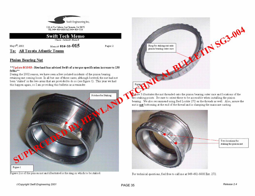
SUPERCEDED BY HEWLAND TECHNICAL BULLETIN SG3-004

PAGE 36 Release 2.4 Copyright Swift Engineering 2001

PAGE 37 Copyright Swift Engineering 2001 Release 2.4

PAGE 38 Release 2.4 Copyright Swift Engineering 2001
30th March 2004
SG3 Technical Bulletin No. 003
Differential Bevel Gear Revision
Subsequent to the AF type planetary bevel gears specified in Technical Bulletin No.001, the design of the gear teeth has been updated to further improve tooth strength, and therefore crack resistance. The new side bevel gear part number is HCC-213-6AH The new planet bevel gear part number is FTC-213-5AH These two new parts will only mesh correctly with each other and cannot be used with any previous version. The new parts are easily visually identified as they have part numbers marked on them. Also the teeth are slightly curved (as opposed to all previous version having straight teeth).

PAGE 39 Copyright Swift Engineering 2001 Release 2.4
30th March 2004
SG3 Technical Bulletin No. 004
Pinion Bearing Nut Revision
Some Formula Atlantic users have reported instances of pinion bearing nuts coming loose. The previous step of increasing the tightening torque has proved only partially successful, so we have manufactured a replacement nut from a tougher material. This revision allows the nut to be tightened to a greater torque value than it’s predecessor (see SG3 gearbox manual page 5). The replacement nut is part number NUT-031