Embed Size (px)
Citation preview

Swift SF314-51
SERVICE GUIDE

ii
Revision HistoryRefer to the table below for the updates made to this Swift SF314-51 service guide.
DisclaimerThe information in this guide is subject to change without notice.
There are no representations or warranties, either expressed or implied, with respect to the contents hereof and specifically disclaims any warranties of merchantability or fitness for any particular purpose. The software described in this manual is sold or licensed "as is". Should the programs prove defective following their purchase, the buyer (not the manufacturer, distributor, or its dealer) assumes the entire cost of all necessary servicing, repair, and any incidental or consequential damages resulting from any defect in the software.
Copyright© 2016 by Acer Incorporated. All rights reserved. No part of this publication may be reproduced, transmitted, transcribed, stored in a retrieval system, or translated into any language or computer language, in any form or by any means, electronic, mechanical, magnetic, optical, chemical, manual or otherwise, without the prior written permission of Acer Incorporated.
ConventionsThe following conventions are used in this manual:
WARNING:!
Indicates a potential for personal injury.
CAUTION:!
Indicates a potential loss of data or damage to equipment.
IMPORTANT:+Indicates information that is important to know for the proper completion of a procedure, choice of an option, or completing a task.
The following typographical conventions are used in this document:
Book titles, directory names, file names, path names, and program/process names are shown in italics.
Example:
the DRS5 User's Guide
/usr/local/bin/fd
Date Revision Chapter Updates
2016/8/15 First Release

iii
the /TPH15spool_M program
Computer output (text that represents information displayed on a computer screen, such as menus, prompts, responses to input, and error messages) are shown in constant width.
Example:
[01] The server has been stopped
User input (text that represents information entered by a computer user, such as command names, option letters, and words) are shown in constant width bold.
Variables contained within user input are shown in angle brackets (< >).
Example:
At the prompt, type run <file name> -m
Keyboard keys are shown in bold italics.
Example:
After entering the data, press Enter.
General information 0
Before using this information and the product it supports, read the following general information.
This service guide provides you with all technical information relating to the basic configuration for Acer’s global product offering. To better fit local market requirements and enhance product competitiveness, your regional office may have decided to extend the functionality of a machine (such as add-on cards, modems, or extra memory capabilities). These localized features are not covered in this generic service guide. In such cases, contact your regional offices or the responsible personnel/channel to provide you with further technical details.
When ordering FRU parts: Check the most up-to-date information available on your regional Web or channel. If, for whatever reason, a part number change is made, it may not be noted in this printed service guide.
Acer-authorized Service Providers: Your Acer office may have a different part number code than those given in the FRU list in this service guide. You must use the list provided by your regional Acer office to order FRU parts for repair and service of customer machines.

iv

ii-v
CHAPTER 1Hardware Specifications
Features . . . . . . . . . . . . . . . . . . . . . . . . . . . . . . . . . . . . . . . . . . . . 1-5Operating System. . . . . . . . . . . . . . . . . . . . . . . . . . . . . . . . . . .1-5Platform . . . . . . . . . . . . . . . . . . . . . . . . . . . . . . . . . . . . . . . . . .1-5System Memory . . . . . . . . . . . . . . . . . . . . . . . . . . . . . . . . . . . .1-5Display. . . . . . . . . . . . . . . . . . . . . . . . . . . . . . . . . . . . . . . . . . . .1-5Graphics . . . . . . . . . . . . . . . . . . . . . . . . . . . . . . . . . . . . . . . . . .1-5Storage Subsystem . . . . . . . . . . . . . . . . . . . . . . . . . . . . . . . . . .1-6Audio Subsystem . . . . . . . . . . . . . . . . . . . . . . . . . . . . . . . . . . .1-6Communication . . . . . . . . . . . . . . . . . . . . . . . . . . . . . . . . . . . .1-7Privacy Control . . . . . . . . . . . . . . . . . . . . . . . . . . . . . . . . . . . . .1-7Dimensions and Weight. . . . . . . . . . . . . . . . . . . . . . . . . . . . . .1-7Power Adapter and Battery. . . . . . . . . . . . . . . . . . . . . . . . . . .1-7Special Keys and Controls . . . . . . . . . . . . . . . . . . . . . . . . . . . .1-8I/O Ports. . . . . . . . . . . . . . . . . . . . . . . . . . . . . . . . . . . . . . . . . . .1-8Software . . . . . . . . . . . . . . . . . . . . . . . . . . . . . . . . . . . . . . . . . .1-8Environment . . . . . . . . . . . . . . . . . . . . . . . . . . . . . . . . . . . . . . .1-9
Notebook Tour. . . . . . . . . . . . . . . . . . . . . . . . . . . . . . . . . . . . . . . 1-10Screen View . . . . . . . . . . . . . . . . . . . . . . . . . . . . . . . . . . . . . . .1-10Keyboard View . . . . . . . . . . . . . . . . . . . . . . . . . . . . . . . . . . . . .1-11Left View. . . . . . . . . . . . . . . . . . . . . . . . . . . . . . . . . . . . . . . . . .1-12Right View . . . . . . . . . . . . . . . . . . . . . . . . . . . . . . . . . . . . . . . .1-13Base View . . . . . . . . . . . . . . . . . . . . . . . . . . . . . . . . . . . . . . . . .1-14Indicators . . . . . . . . . . . . . . . . . . . . . . . . . . . . . . . . . . . . . . . . .1-15Touchpad Basics . . . . . . . . . . . . . . . . . . . . . . . . . . . . . . . . . . . .1-16Using the Keyboard . . . . . . . . . . . . . . . . . . . . . . . . . . . . . . . . .1-18Lock Keys. . . . . . . . . . . . . . . . . . . . . . . . . . . . . . . . . . . . . . . . . .1-18Windows Keys. . . . . . . . . . . . . . . . . . . . . . . . . . . . . . . . . . . . . .1-19Hotkeys . . . . . . . . . . . . . . . . . . . . . . . . . . . . . . . . . . . . . . . . . . .1-21
Specification Tables . . . . . . . . . . . . . . . . . . . . . . . . . . . . . . . . . . . 1-24
CHAPTER 2System Utilities
BIOS Setup Utility. . . . . . . . . . . . . . . . . . . . . . . . . . . . . . . . . . . . . 2-3Navigating the BIOS Utility . . . . . . . . . . . . . . . . . . . . . . . . . . .2-3
BIOS . . . . . . . . . . . . . . . . . . . . . . . . . . . . . . . . . . . . . . . . . . . . . . . 2-4Information. . . . . . . . . . . . . . . . . . . . . . . . . . . . . . . . . . . . . . . .2-4Main . . . . . . . . . . . . . . . . . . . . . . . . . . . . . . . . . . . . . . . . . . . . .2-5Advanced . . . . . . . . . . . . . . . . . . . . . . . . . . . . . . . . . . . . . . . . .2-7Security . . . . . . . . . . . . . . . . . . . . . . . . . . . . . . . . . . . . . . . . . . .2-9

ii-vi
Boot. . . . . . . . . . . . . . . . . . . . . . . . . . . . . . . . . . . . . . . . . . . . . .2-14Exit. . . . . . . . . . . . . . . . . . . . . . . . . . . . . . . . . . . . . . . . . . . . . . .2-15
BIOS Flash Utilities . . . . . . . . . . . . . . . . . . . . . . . . . . . . . . . . . . . . 2-16WinFlash Utility . . . . . . . . . . . . . . . . . . . . . . . . . . . . . . . . . . . .2-17
Remove HDD/BIOS Password Utilities. . . . . . . . . . . . . . . . . . . . . 2-19Remove HDD Password Utilities . . . . . . . . . . . . . . . . . . . . . . .2-19Cleaning BIOS Passwords . . . . . . . . . . . . . . . . . . . . . . . . . . . . .2-21
Using DMI Tools . . . . . . . . . . . . . . . . . . . . . . . . . . . . . . . . . . . . . . 2-23Update Manufacture Name. . . . . . . . . . . . . . . . . . . . . . . . . . .2-23Update Product Name . . . . . . . . . . . . . . . . . . . . . . . . . . . . . . .2-26Update Serial Number . . . . . . . . . . . . . . . . . . . . . . . . . . . . . . .2-29Update Motherboard Serial Number . . . . . . . . . . . . . . . . . . .2-32Update UUID. . . . . . . . . . . . . . . . . . . . . . . . . . . . . . . . . . . . . . .2-35Update Asset Tag . . . . . . . . . . . . . . . . . . . . . . . . . . . . . . . . . . .2-40Crisis Disk Utility . . . . . . . . . . . . . . . . . . . . . . . . . . . . . . . . . . . .2-44
CHAPTER 3Machine Maintenance
Machine Disassembly and Replacement. . . . . . . . . . . . . . . . . . . 3-5Recommended Equipment . . . . . . . . . . . . . . . . . . . . . . . . . . .3-5Replacement Requirements. . . . . . . . . . . . . . . . . . . . . . . . . . .3-5Pre-disassembly Instructions . . . . . . . . . . . . . . . . . . . . . . . . . .3-6Disassembly Process . . . . . . . . . . . . . . . . . . . . . . . . . . . . . . . . .3-7
Main Unit Disassembly Process . . . . . . . . . . . . . . . . . . . . . . . . . . 3-8Main Unit Disassembly Flowchart . . . . . . . . . . . . . . . . . . . . . .3-8Removing the Bottom Cover . . . . . . . . . . . . . . . . . . . . . . . . . .3-9Removing the Battery . . . . . . . . . . . . . . . . . . . . . . . . . . . . . . .3-13Removing the IO Board . . . . . . . . . . . . . . . . . . . . . . . . . . . . . .3-15Removing the Speaker . . . . . . . . . . . . . . . . . . . . . . . . . . . . . . .3-16Removing the WLAN Card . . . . . . . . . . . . . . . . . . . . . . . . . . . .3-19Removing the RTC Battery. . . . . . . . . . . . . . . . . . . . . . . . . . . .3-21Removing the Thermal Module. . . . . . . . . . . . . . . . . . . . . . . .3-22Removing the SSD Module . . . . . . . . . . . . . . . . . . . . . . . . . . .3-27Removing the Motherboard . . . . . . . . . . . . . . . . . . . . . . . . . .3-29Removing the Finger Printer Sensor . . . . . . . . . . . . . . . . . . . .3-33Removing the LCD Module . . . . . . . . . . . . . . . . . . . . . . . . . . .3-34Removing the Touch Pad. . . . . . . . . . . . . . . . . . . . . . . . . . . . .3-37Removing the LCD Bezel . . . . . . . . . . . . . . . . . . . . . . . . . . . . .3-39Removing the LCD Panel . . . . . . . . . . . . . . . . . . . . . . . . . . . . .3-40Removing the Hinge Cap. . . . . . . . . . . . . . . . . . . . . . . . . . . . .3-43Removing the Camera . . . . . . . . . . . . . . . . . . . . . . . . . . . . . . .3-45

ii-vii
Removing the eDP Cable . . . . . . . . . . . . . . . . . . . . . . . . . . . . .3-46Removing the Hinges . . . . . . . . . . . . . . . . . . . . . . . . . . . . . . . .3-47
Main Unit Reassembly Procedure . . . . . . . . . . . . . . . . . . . . . . . . 3-48Replacing the eDP Cable . . . . . . . . . . . . . . . . . . . . . . . . . . . . .3-49Replacing the Camera . . . . . . . . . . . . . . . . . . . . . . . . . . . . . . .3-50Replacing the Hinge Cap. . . . . . . . . . . . . . . . . . . . . . . . . . . . .3-51Replacing the LCD Panel . . . . . . . . . . . . . . . . . . . . . . . . . . . . .3-52Replacing the LCD Bezel . . . . . . . . . . . . . . . . . . . . . . . . . . . . .3-54Replacing the Touch Pad . . . . . . . . . . . . . . . . . . . . . . . . . . . . .3-55Replacing the LCD Module . . . . . . . . . . . . . . . . . . . . . . . . . . .3-56Replacing the Finger Printer Sensor . . . . . . . . . . . . . . . . . . . .3-60Replacing the Motherboard . . . . . . . . . . . . . . . . . . . . . . . . . .3-61Replacing the SSD Module. . . . . . . . . . . . . . . . . . . . . . . . . . . .3-65Replacing the Thermal Module . . . . . . . . . . . . . . . . . . . . . . . .3-67Replacing the RTC Battery . . . . . . . . . . . . . . . . . . . . . . . . . . . .3-70Replacing the WLAN Card . . . . . . . . . . . . . . . . . . . . . . . . . . . .3-71Replacing the Speaker . . . . . . . . . . . . . . . . . . . . . . . . . . . . . . .3-73Replacing the IO Board . . . . . . . . . . . . . . . . . . . . . . . . . . . . . .3-76Replacing the Battery . . . . . . . . . . . . . . . . . . . . . . . . . . . . . . .3-77Replacing the Bottom Cover . . . . . . . . . . . . . . . . . . . . . . . . .3-78
CHAPTER 4Troubleshooting
Introduction . . . . . . . . . . . . . . . . . . . . . . . . . . . . . . . . . . . . . . . . . 4-3General Information . . . . . . . . . . . . . . . . . . . . . . . . . . . . . . . . . . 4-3
Power On Issues . . . . . . . . . . . . . . . . . . . . . . . . . . . . . . . . . . . .4-4No Display Issues. . . . . . . . . . . . . . . . . . . . . . . . . . . . . . . . . . . .4-5LCD Failure . . . . . . . . . . . . . . . . . . . . . . . . . . . . . . . . . . . . . . . .4-7Keyboard Failure . . . . . . . . . . . . . . . . . . . . . . . . . . . . . . . . . . .4-8Touchpad Failure . . . . . . . . . . . . . . . . . . . . . . . . . . . . . . . . . . .4-9Internal & External Speaker Failure . . . . . . . . . . . . . . . . . . . .4-10Microphone Failure . . . . . . . . . . . . . . . . . . . . . . . . . . . . . . . . .4-12USB Failure . . . . . . . . . . . . . . . . . . . . . . . . . . . . . . . . . . . . . . . .4-13WLAN Failure . . . . . . . . . . . . . . . . . . . . . . . . . . . . . . . . . . . . . .4-14Card Reader Failure . . . . . . . . . . . . . . . . . . . . . . . . . . . . . . . . .4-15Thermal Unit Failure . . . . . . . . . . . . . . . . . . . . . . . . . . . . . . . .4-16HDMI Failure. . . . . . . . . . . . . . . . . . . . . . . . . . . . . . . . . . . . . . .4-17Other Functions Failure . . . . . . . . . . . . . . . . . . . . . . . . . . . . . .4-18
Intermittent Problems . . . . . . . . . . . . . . . . . . . . . . . . . . . . . . . . . 4-18Undetermined Problems . . . . . . . . . . . . . . . . . . . . . . . . . . . . . . . 4-18

ii-viii
Post Codes . . . . . . . . . . . . . . . . . . . . . . . . . . . . . . . . . . . . . . . . . . 4-19POST Code Range. . . . . . . . . . . . . . . . . . . . . . . . . . . . . . . . . . .4-19
CHAPTER 5Jumper and Connector Locations
Clearing Password Check and BIOS Recovery . . . . . . . . . . . . . . 5-5Clearing Password Check . . . . . . . . . . . . . . . . . . . . . . . . . . . . .5-5Clear CMOS Jumper . . . . . . . . . . . . . . . . . . . . . . . . . . . . . . . . .5-6BIOS Recovery by Crisis Disk. . . . . . . . . . . . . . . . . . . . . . . . . . .5-7
CHAPTER 6FRU List
Exploded Diagrams . . . . . . . . . . . . . . . . . . . . . . . . . . . . . . . . . . . 6-4Main Assembly . . . . . . . . . . . . . . . . . . . . . . . . . . . . . . . . . . . . .6-4
FRU List . . . . . . . . . . . . . . . . . . . . . . . . . . . . . . . . . . . . . . . . . . . . . 6-6Screw List . . . . . . . . . . . . . . . . . . . . . . . . . . . . . . . . . . . . . . . . . . . 6-16
CHAPTER 7Test Compatible Components
Microsoft® Windows® 10 Environment Test . . . . . . . . . . . . . . 7-4Swift SF314-51 . . . . . . . . . . . . . . . . . . . . . . . . . . . . . . . . . . . . .7-4
CHAPTER 8Online Support Information
Introduction . . . . . . . . . . . . . . . . . . . . . . . . . . . . . . . . . . . . . . . . . 8-3

CHAPTER 1Hardware Specifications

1-2
Features . . . . . . . . . . . . . . . . . . . . . . . . . . . . . . . . . . . . . . . . . . . . 1-5Operating System. . . . . . . . . . . . . . . . . . . . . . . . . . . . . . . . . . .1-5Platform . . . . . . . . . . . . . . . . . . . . . . . . . . . . . . . . . . . . . . . . . .1-5System Memory . . . . . . . . . . . . . . . . . . . . . . . . . . . . . . . . . . . .1-5Display. . . . . . . . . . . . . . . . . . . . . . . . . . . . . . . . . . . . . . . . . . . .1-5Graphics . . . . . . . . . . . . . . . . . . . . . . . . . . . . . . . . . . . . . . . . . .1-5Storage Subsystem . . . . . . . . . . . . . . . . . . . . . . . . . . . . . . . . . .1-6Audio Subsystem . . . . . . . . . . . . . . . . . . . . . . . . . . . . . . . . . . .1-6Communication . . . . . . . . . . . . . . . . . . . . . . . . . . . . . . . . . . . .1-7Privacy Control . . . . . . . . . . . . . . . . . . . . . . . . . . . . . . . . . . . . .1-7Dimensions and Weight. . . . . . . . . . . . . . . . . . . . . . . . . . . . . .1-7Power Adapter and Battery. . . . . . . . . . . . . . . . . . . . . . . . . . .1-7Special Keys and Controls . . . . . . . . . . . . . . . . . . . . . . . . . . . .1-8I/O Ports. . . . . . . . . . . . . . . . . . . . . . . . . . . . . . . . . . . . . . . . . . .1-8Software . . . . . . . . . . . . . . . . . . . . . . . . . . . . . . . . . . . . . . . . . .1-8Environment . . . . . . . . . . . . . . . . . . . . . . . . . . . . . . . . . . . . . . .1-9
Notebook Tour. . . . . . . . . . . . . . . . . . . . . . . . . . . . . . . . . . . . . . . 1-10Screen View . . . . . . . . . . . . . . . . . . . . . . . . . . . . . . . . . . . . . . .1-10Keyboard View . . . . . . . . . . . . . . . . . . . . . . . . . . . . . . . . . . . . .1-11Left View. . . . . . . . . . . . . . . . . . . . . . . . . . . . . . . . . . . . . . . . . .1-12Right View . . . . . . . . . . . . . . . . . . . . . . . . . . . . . . . . . . . . . . . .1-13Base View . . . . . . . . . . . . . . . . . . . . . . . . . . . . . . . . . . . . . . . . .1-14Indicators . . . . . . . . . . . . . . . . . . . . . . . . . . . . . . . . . . . . . . . . .1-15Touchpad Basics . . . . . . . . . . . . . . . . . . . . . . . . . . . . . . . . . . . .1-16Using the Keyboard . . . . . . . . . . . . . . . . . . . . . . . . . . . . . . . . .1-18Lock Keys. . . . . . . . . . . . . . . . . . . . . . . . . . . . . . . . . . . . . . . . . .1-18Windows Keys. . . . . . . . . . . . . . . . . . . . . . . . . . . . . . . . . . . . . .1-19Hotkeys . . . . . . . . . . . . . . . . . . . . . . . . . . . . . . . . . . . . . . . . . . .1-21System Block Diagram. . . . . . . . . . . . . . . . . . . . . . . . . . . . . . . . . . . . . . . . . 1-23
Specification Tables . . . . . . . . . . . . . . . . . . . . . . . . . . . . . . . . . . . 1-24Computer specifications. . . . . . . . . . . . . . . . . . . . . . . . . . . . . . . . . . . . . . . . 1-24System Board Major Chips . . . . . . . . . . . . . . . . . . . . . . . . . . . . . . . . . . . . . 1-25Processor . . . . . . . . . . . . . . . . . . . . . . . . . . . . . . . . . . . . . . . . . . . . . . . . . . . 1-25Processor Specifications . . . . . . . . . . . . . . . . . . . . . . . . . . . . . . . . . . . . . . . 1-25UMA CPU Fan1 True Value Table (Tj100) . . . . . . . . . . . . . . 1-26UMA CPU Fan2 True Value Table (Tj100) . . . . . . . . . . . . . . 1-26System Memory . . . . . . . . . . . . . . . . . . . . . . . . . . . . . . . . . . . . . . . . . . . . . . 1-26Graphics Controller . . . . . . . . . . . . . . . . . . . . . . . . . . . . . . . . . . . . . . . . . . . 1-26BIOS. . . . . . . . . . . . . . . . . . . . . . . . . . . . . . . . . . . . . . . . . . . . . . . . . . . . . . . 1-27Keyboard . . . . . . . . . . . . . . . . . . . . . . . . . . . . . . . . . . . . . . . . . . . . . . . . . . . 1-27Hard Disk Drive (AVL components) . . . . . . . . . . . . . . . . . 1-28LCD 14.0” (FHD, None Glare) . . . . . . . . . . . . . . . . . . . . . . . . . . . . . . . . . . . 1-30LCD 14.0” (HD, None Glare) . . . . . . . . . . . . . . . . . . . . . . . . . . . . . . . . . . . . 1-30FHD Display Supported Resolution (System Supported Resolution) . . . . . 1-30HD Display Supported Resolution (System Supported Resolution). . . . . . . 1-31Camera . . . . . . . . . . . . . . . . . . . . . . . . . . . . . . . . . . . . . . . . . . . . . . . . . . . . 1-31Audio Codec and Amplifier . . . . . . . . . . . . . . . . . . . . . . . . . . . . . . . . . . . . . 1-31Audio Interface . . . . . . . . . . . . . . . . . . . . . . . . . . . . . . . . . . . . . . . . . . . . . . . 1-33WLAN Combo Card . . . . . . . . . . . . . . . . . . . . . . . . . . . . . . . . . . . . . . . . . . . 1-33

1-3
Battery . . . . . . . . . . . . . . . . . . . . . . . . . . . . . . . . . . . . . . . . . . . . . . . . . . . . . 1-34USB Port . . . . . . . . . . . . . . . . . . . . . . . . . . . . . . . . . . . . . . . . . . . . . . . . . . . 1-34HDMI Port . . . . . . . . . . . . . . . . . . . . . . . . . . . . . . . . . . . . . . . . . . . . . . . . . . 1-34AC Adapter. . . . . . . . . . . . . . . . . . . . . . . . . . . . . . . . . . . . . . . . . . . . . . . . . . 1-35System Power Management . . . . . . . . . . . . . . . . . . . . . . . . . . . . . . . . . . . . 1-35Card Reader. . . . . . . . . . . . . . . . . . . . . . . . . . . . . . . . . . . . . . . . . . . . . . . . . 1-36System LED Indicator . . . . . . . . . . . . . . . . . . . . . . . . . . . . . . . . . . . . . . . . . 1-36System DMA Specification. . . . . . . . . . . . . . . . . . . . . . . . . . . . . . . . . . . . . . 1-37System Interrupt Specification . . . . . . . . . . . . . . . . . . . . . . . . . . . . . . . . . . . 1-37. . . . . . . . . . . . . . . . . . . . . . . . . . . . . . . . . . . . . . . . . . . . . . . . . . . . . . . . . . . 1-39

1-4

Hardware Specifications and Configurations 1-5
Hardware Specifications and Configurations
Features 0
The following is a brief summary of the computer’s many features:
Operating System 0
Windows® 10 64-bit
Platform 0
Intel® Core™ i3-6100U processor (3 MB L3 cache, 2.30 GHz, 15W) supporting Intel® 64
architecture, Intel® Smart Cache
Intel® Core™ i5-6200U processor (3 MB L3 cache, 2.30 GHz, 15W) supporting Intel® 64
architecture, Intel® Smart Cache
Intel® Core™ i7-6500U processor (4 MB L3 cache, 2.50 GHz, 15W) supporting Intel® 64
architecture, Intel® Smart Cache
Intel® PENTIUM® 4405U processor (2 MB L3 cache, 2.10 GHz, 15W) supporting Intel® 64
architecture, Intel® Smart Cache
Intel® 100 series Chipset family
System Memory 0
On board up to 8G DDR4 support
Display 0
14.0" FHD 1920 x 1080 resolution, high-brightness (220-nit) LED-backlit none Glare TFT LCD, 30 ms typical response time
14.0" FHD 1920 x 1080 resolution, high-brightness (250-nit) LED-backlit none Glare TFT LCD, 25 ms typical response time
14.0" HD 1366 x 768 resolution, high-brightness (220 -nit) LED-backlit none Glare TFT LCD, 8 ms typical response time
14.0" HD 1366 x 768 resolution, high-brightness (220 -nit) LED-backlit none Glare TFT LCD, 10 ms typical response time
Mercury-free, environment-friendly
LED-backlight with driving circuit design
16:9 aspect ratio
Graphics 0
Intel® HD Graphics 520 with 300-1024MHz frequency, supporting Intel® Clear Video HD
Technology,Intel® Clear Video HD Technology, Intel® Quick Sync Video ,Intel® InTru™ 3D
Technology ,Intel® Insider™ ,Intel® Wireless Display, Intel® Clear Video Technology, HDMI, Microsoft® DirectX® 12, OpenGL® 4.4

1-6 Hardware Specifications and Configurations
Triple independent display support9.43 million colors
External resolution / refresh rates:
HDMI® port up to 4096 x 2304: 24 Hz
DP port up to 4096 x 2304: 60 Hz
eDP port up to 4096 x 2304: 60 Hz
HDMI® (High-Definition Multimedia Interface) interface support HDMI with 3D, 4Kx2K@24HZ, deep color, and x,v,color.
Intel® HD Graphics 510 with 300-950MHz frequency, supporting Intel® Quick Sync
Video,Intel® Wireless Display, Intel® Clear Video Technology, Intel® Clear Video HD Technology, Microsoft® DirectX® 12, OpenGL® 4.4
Triple independent display support9.43 million colors
External resolution / refresh rates:
HDMI® port up to 4096 x 2304: 24 Hz
DP port up to 4096 x 2304: 60 Hz
eDP port up to 4096 x 2304: 60 Hz
HDMI® (High-Definition Multimedia Interface) interface support HDMI with 3D, 4Kx2K@24HZ, deep color, and x,v,color
Storage Subsystem 0
Hard disk drive 0
M.2 2280 SATA Gen3x2 SSD
128GB/256GB/512GB SSD
SD card reader, supporting: 0
Secure DigitalTM(SD), MultiMediaCardTM(MMC), SDHC, SDXC, Mini-SD, Micro-SD (T-flash),RS-MMC, Mobile-MMC, MMCPlus and MMC-micro
Memory StickTM(MS), Memory Stick PROTM(MS-PRO), MS Duo, MS-PRO Duo and Micro-MS (M2)
MSPRO-HG Duo 8-bit mode
xD-Picture CardTM (xD) including Type M, Type M+ and Type H
Audio Subsystem 0
Two built-in stereo speakers
High-definition audio support
Direct Sound 3D™ compatible
EAX™ 1.0 & 2.0 compatible
I3DL2 compatible
Built-in digital microphone

Hardware Specifications and Configurations 1-7
Communication 0
Webcam 0
Video Conference, featuring:
1.0M webcam with 1280*720 effective resolution
USB 2.0 High Speed interface
Supports 720P resolution online image applications
Wireless and networking 0
WLAN:
WiFi 2X2 802.11a/b/g/n
WiFi 2X2 802.11b/g/n
WiFi 2X2 802.11ac
Privacy Control 0
BIOS user/supervisor password
Kensington lock slot
Dimensions and Weight 0
Dimensions 0
341 (L) x 236.6(W) x 17.95(H) mm
Weight 0
1.65kg with battery
Power Adapter and Battery 0
ACPI 5.0 CPU power management standard: supports Standby and Hibernation power-saving modes
Power adapter 0
3-pin 45 W AC adapter:
1.1 (W) x 3.0 (D) x 7.7 (H) mm
Battery 0
3220 mAh 4-cell LGC/SANYO for 5.5mm battery pack thickness

1-8 Hardware Specifications and Configurations
Special Keys and Controls 0
Keyboard 0
AR-87/GR-87/HE-87/KO-87/RU-87/TA-87/TW-87/UI-87/A1-88/BE-88/BG-88/BR-88/CF-88/DE-88/E2-88/FR-88/GE-88/HU-88/IT-88/LA-88/ND-88/NW-88/PO-88/SD-88/SF-88/SP-88/TU-88/UK-88/WB-88/JP-91-key-layout keyboard with embedded numeric keypad, international language support
Touchpad 0
Multi-finger gesture touchpad, supporting single finger press or tap or slide, Two-finger press ,slide ,pinch ,Three-finger press ,swipe
Media keys 0
Media controls: Pause/Play/stop/Previous/next
Volume controls: up/down
I/O Ports 0
SD card reader
1 USB 2.0 port
1 USB 3.0/Offline USB Charger port
1 Type C USB3.1 Gen 1+PD+DP port
HDMI® port
Headphone/speaker/line-out jack
DC-in jack for AC adapter
1, K lock
Software 0
Content 0
abFiles (For Win10)
abPhoto (For Win10)
Acer Care Center V2 (For Win10 RS1)
Acer Configuration Manager
Acer Portal (Win10)
Agoda Weblink (Win10)
Amazon (Win10)
App Explorer
BaiduIME
Booking.com Weblink (Win10)
Dashlane
eBay Worldwide (Win10)
Firefox
Gomaji (Win10)
Hao123 Weblink (Win10)

Hardware Specifications and Configurations 1-9
Internet Explorer (Jumpstart 2016)
Kindle (Win10)
Lazada
McAfee Internet Security (Win10)
McAfee Settings (For Win10)
Music Maker Jam (Win10)
Netflix (Win10)
Office 2016
Office 2016 Installer
PC Manager
PowerDVD (Win10)
Priceline.com
Pubu
Quick Access (For Win10)
Quick Access Settings (For Win10)
Software Value Pack
Sohu Video (Win10)
User Behavior Tracking Framework (For Win10)
WildTangent Game List Setting (For Win10)
WildTangent Games (Win10)
WildTangent _Remove_From_4K
Yandex Weblink (Win10)
Environment 0
Temperature:
Operating: 0°C to 40°C
Non-operating: -20°C to 60°C
Humidity (non-condensing):
Operating: 0% to 80%
Non-operating: 20% to 80%

1-10 Hardware Specifications and Configurations
Notebook Tour 0
This section provides an overview of the features and functions of the notebook.
Screen View 0
Figure 1-1. Screen View
Table 1-1. Screen View
No Icon Item Description
1 Webcam Web camera for video communication.
A light next to the webcam indicates that the webcam is active.
2 screen Displays computer output
1
2

Hardware Specifications and Configurations 1-11
Keyboard View 0
Figure 1-2. Keyboard View
Table 1-2. Keyboard View
No Icon Item Description
1 Keyboard For entering data into your computer.
2 Microphone Internal digital microphone for sound recording.
3 Touchpad Touch-sensitive pointing device.The touchpad and selection buttons form a single surface.Press down firmly on the touchpad surface to perform a left click.Press down firmly on the lower right corner to perform a right click.
4 Fingerprint reader Fingerprint reader for Acer ProShield Security Suite (configuration may vary by model).
5 Power button Turns the computer on and off.
4
5
1
3
2

1-12 Hardware Specifications and Configurations
Left View 0
Figure 1-3. Left View
NOTE:NOTE:Information on USB 3.0
USB 3.0 compatible ports are blue.
Compatible with USB 3.0 and earlier devices.
For optimal performance, use USB 3.0-certified devices.
Defined by the USB 3.0 specification (SuperSpeed USB).
NOTE:NOTE:USB Type-C information
Table 1-3. Left View
No Icon Item Description
1 DC-in jack Connects to an AC adapter.
2 HDMI port Supports high-definition digital video connections.
3 USB port with power-off charging
Connects to USB devices.
4 USB Type-C port Connects to USB devices that adopt the USB Type-C connector. Supports Display Port over USB-C
5 Power indicator Indicates the computer’s power status.
Battery indicator Indicates the computer’s battery status.
Charging: The light show amber when the battery is charging.Fully charged: The light show blue when in AC mode.
1 2 3 4 5

Hardware Specifications and Configurations 1-13
USB 3.1 Gen 1 with transfer speeds up to 5 Gps.
Supports DisplayPort™ over USB-C ™ audio/video output.
Delivers up to 3 A at 5 V DC for USB charging.
Right View 0
Figure 1-4. Right View
Table 1-4. Right View
No Icon Item Description
1 SD Card reader Accepts one Secure Digital (SD or SDHC) card.
Note: Only one card can operate at a time.
2 Headphones/speaker jack
Connects to audio devices (e.g., speakers, headphones) or a headset with microphone.
3 USB port Connects to USB devices.
4 Kensington lock slot Connects to a Kensington-compatible computer security lock.
Wrap the computer security lock cable around an immovable object such as a table or handle of a locked drawer. Insert the lock into the notch and turn the key to secure the lock. Some keyless models are also available.
3 421

1-14 Hardware Specifications and Configurations
Base View 0
Figure 1-5. Base View
Table 1-5. Base View
No Icon Item Description
1 Battery reset pinhole Simulates removing and reinstalling the battery.Insert a paperclip into the hole and press for four seconds.
2 Speakers Deliver stereo audio output.
1
2

Hardware Specifications and Configurations 1-15
Indicators 0
The computer has two easy-to-read status indicators. The following indicators are visible even when the computer cover is closed.
Table 1-6. Indicators
Icon Function Description
Power indicator Indicates the computer’s power status.
Battery indicator Indicates the computer’s battery status.
Charging: The light show amber when the battery is charging.Fully charged: The light show blue when in AC mode.

1-16 Hardware Specifications and Configurations
Touchpad Basics 0
The touchpad controls the arrow (or 'cursor') on the screen. As you slide your finger across the touchpad, the cursor will follow this movement.The Precision Touchpad (PTP) is designed to provide a more uniform, smooth, and accurate touchpad experience. Many applications support precision touchpad gestures that use one or more fingers, however, some gestures may not be supported by the specific application or program you are using.
NOTE:NOTE:The touchpad is sensitive to finger movement; the lighter the touch, the better the response.
Please keep the touchpad and your fingers dry and clean.
Support for touchpad gestures depends on the active application.
These allow you to control applications with a few simple gestures, such as:
Single-finger slide: Slide a finger across the touchpad to move the cursor.
Figure 1-6. Single-finger slide
Single-finger press or tap:Press the touchpad down, or lightly tap the touchpad with your finger, to perform a 'click', which will select or start an item. Quickly repeat the tap to perform a double tap or 'double click'.
Figure 1-7. Single-finger press or tap
Two-finger press: Lightly tap the touchpad with two fingers to perform a 'right click'. In the Start screen, this will toggle the app commands. In most apps this will open a context menu related to the selected item.
Figure 1-8. Two-finger press
Two-finger slide: Swiftly scroll through web pages, documents and playlists by placing two fingers on the touchpad and moving both in any direction.

Hardware Specifications and Configurations 1-17
Figure 1-9. Two-finger slide
Two-finger pinch: Zoom in and out of photos, maps and documents with a simple finger-and-thumb gesture.
Figure 1-10. Two-finger pinch
Three-finger press: Lightly tap the touchpad with three fingers to open Cortana (if your computer supports Cortana) or open the Action Center (if your computer does not support Cortana).
Figure 1-11. Three-finger press
Three-finger swipe: Swipe across the touchpad with three fingers.
Swipe up to open Task Vi ew. Move the cursor over a window and tap the touchpad to select that window, or swipe downwards to exit Task View.
Swipe down to minimize all open windows and show Desktop; swipe upwards to restore the minimized windows.
Swipe left or right to switch between open windows.
Figure 1-12. Three-finger swipe

1-18 Hardware Specifications and Configurations
Using the Keyboard 0
The keyboard has full-sized keys and a embedded numeric keypad, separate cursor,lock, Windows, function and special keys.
Figure 1-13. Keyboard Lock Keys
Lock Keys 0
The keyboard has three lock keys which the user can toggle on and off.
Table 1-7. Lock Keys
Lock key Description
Caps Lock When Caps Lock is on, all alphabetic characters typed are in uppercase.
Num Lock When Num Lock is on, the embedded keypad is in numeric mode. The keys function as a calculator (complete with the arithmetic operators +, -, *, and /). Use this mode when you need to do a lot of numeric data entry.
Scroll Lock
<Fn> +<F12> When Scroll Lock is on, the screen moves one line up or down when you press the up or down arrow keys respectively. Scroll Lock does not work with some applications.
The embedded numeric keypad functions like a desktop numeric keypad. It is indicated by small characters located on the upper right corner of the keycaps. To simplify the keyboard legend, cursor-control key symbols are not printed on the keys.

Hardware Specifications and Configurations 1-19
Windows Keys 0
The keyboard has two keys that perform Windows-specific functions.
Windows key
Application key
Table 1-8. Windows Keys
Key Description
Windows key Pressed alone, this key brings up the Start Screen. You can start typing to search for an application, just like the Windows 7 Start Menu.
Functions supported by Windows 10:
< >: Start Screen
< > + <D>: Show desktop
< > + <E>: Open Windows Explorer
< > + <F>: Go to Files in Search charm
< > + <G>: Cycle through desktop gadgets
< > + <H>: Share charm
< > + <I>: Settings charm
< > + <J>: Switch focus between snapped and larger apps
< > + <K>: Devices charm
< > + <L>: Switch Users (Lock computer if on a domain)
< > + <M>: Minimize all windows (desktop)
< > + <O>: Lock screen orientation
< > + <P>: Projection options
< > + <Q>: Search charm
< > + <R>: Run...
< > + <T>: Set focus on task and cycle through running desktop apps
< > + <U>: Ease of Access Center
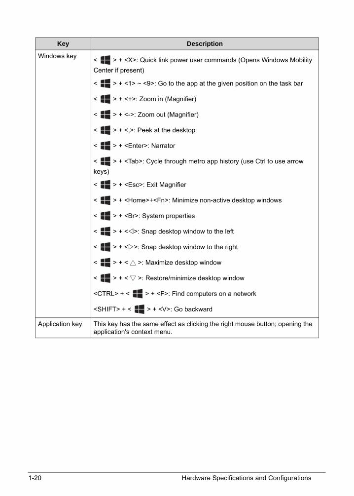
1-20 Hardware Specifications and Configurations
Windows key< > + <X>: Quick link power user commands (Opens Windows Mobility
Center if present)
< > + <1> ~ <9>: Go to the app at the given position on the task bar
< > + <+>: Zoom in (Magnifier)
< > + <->: Zoom out (Magnifier)
< > + <,>: Peek at the desktop
< > + <Enter>: Narrator
< > + <Tab>: Cycle through metro app history (use Ctrl to use arrow
keys)
< > + <Esc>: Exit Magnifier
< > + <Home>+<Fn>: Minimize non-active desktop windows
< > + <Br>: System properties
< > + <>: Snap desktop window to the left
< > + <>: Snap desktop window to the right
< > + < >: Maximize desktop window
< > + < >: Restore/minimize desktop window
<CTRL> + < > + <F>: Find computers on a network
<SHIFT> + < > + <V>: Go backward
Application key This key has the same effect as clicking the right mouse button; opening the application's context menu.
Key Description

Hardware Specifications and Configurations 1-21
Hotkeys 0
The computer employs hotkeys or key combinations to access most computer controls like screen brightness and volume output.
To activate hotkeys, press and hold the <Fn> key before pressing the other key in the hotkey combination.
Figure 1-14. Keyboard Hotkeys
Table 1-9. Hotkeys
Hotkey Icon Function Description
<Fn> + <F3> Airplane mode Turns on / off the computer's network devices.
<Fn> + <F4> Sleep Puts the computer in Sleep mode.
<Fn> + <F5> Display toggle Switches display output between the display screen, external monitor (if connected) and both.
<Fn> + <F6> Display off Turns the display screen backlight off to save power. Press any key to return.
<Fn> + <F7> Touchpad toggle
Turns the built-in touchpad on and off.
<Fn> + <F8> Speaker toggle Turns the speakers on and off.
<Fn> + <F11> NumLk Numeric Lock Turns the number lock feature on or off.
<Fn> + <F12> Scr Lk Scroll Lock Turns Scroll Lock on or off.
<Fn> + <> Brightness up Increases the screen brightness.
<Fn> + <> Brightness down
Decreases the screen brightness.
<Fn> + < > Volume up Increases the sound volume.

1-22 Hardware Specifications and Configurations
<Fn> + < > Volume down Decreases the sound volume.
<Fn> + <Home> Play/Pause Play or pause a selected media file.
<Fn> + <Pg Up> Stop Stop playing the selected media file.
<Fn> + <Pg Dn> Previous Return to the previous media file.
<Fn> + <End> Next Jump to the next media file.
Table 1-9. Hotkeys (Continued)
Hotkey Icon Function Description

Hardware Specifications and Configurations 1-23
System Block Diagram
Skylake U
Discharge Circuit DC & BATT. Conn.
Reset Circuit Skew Holes
TDP 15W
IT8987E/BXEC
Thermal
KB
Click Pad
PANEL
NGFF SSD
PCIE
SPEAKER X 2
HDACOMBO JACK
DEBUG CONN.
SPI ROM (16M)
TPM
Audio CodecREALTEK/ ALC255
eDP
DDI 1/2HDMI
USB 2.0 1/10USB 3.0 Conn x1W/charger
DDR4DDR4 2133MHz
Front Camera /0.3M
USB 3.0 1/4
USB2.0 Conn x1
NGFFWLAN / BT
PCI-E 6/10
LPC
SPI
NUVOTON/NPCT650
Memory Down x4
INTEL
USB 2.0 5/10
Memory Down x4DDR4DDR4 2133MHz
+VCCSA
DDR & VTT
VCCPRIM_CORE
+1.8VSUS
Power+VCORE+VCCGT
System (5V & 3.3V)
+1.0VSUS
+1.5VS
BATTERY CHARGER
DETECT
LOAD SWITCH
Power Protect
PMIC
Channel A
Channel B
USB 2.0 7/10
USB 2.0 2/10
DMIC X 1
Type C
USB 2.0 3/10
USB 3.0 3/4
SATA
DDI 2
AnalogixANX7428
MUX
HDMI RepeaterPS8201A
USB 2.0 4/10
USB 2.0 6/10Fingerprinter
Card ReaderRealtek/RTS5170
USB2.0 8/10
Touch PanelUSB2.0 9/10
SPI ROM (8M)

1-24 Hardware Specifications and Configurations
Specification Tables 0
Computer specifications
Item Metric Imperial
Dimensions
Length 341 mm 13.43 in
Width 236.6 mm 9.31 in
Height 17.95 mm 0.71 in
Weight (equipped with optical drive, flash drive, and battery)
1.65 kg with 4-cell battery 3.64 lbs with 4-cell battery
Input power
Operating voltage 19V at 2.37A Max for 45W
Operating current 2.37A(Max)
Temperature
Operating 0°C to 40°C 32°F to 104°F
Nonoperating -20°C to 60°C -4°F to 140°F
Relative humidity
Operating 0% to 80%
Nonoperating 20% to 80%
Random vibration
Operating 0.60 g zero-to-peak, 5 Hz to 500 Hz, 30 minutes test duration
Nonoperating 1.50 g zero-to-peak, 5 Hz to 500 Hz, 30 minutes per axis test duration
NOTE:Applicable product safety standards specify thermal limits for plastic surfaces. The computer operates within this range of temperatures.

Hardware Specifications and Configurations 1-25
System Board Major Chips
Processor
Processor Specifications
Item Specification
Core logic Intel® 100 series Chipset family
VGA Intel® HD Graphics 520/Intel® HD Graphics 510
USB 3.0 Intel® 100 series Chipset family
Bluetooth (chip of WLAN combo card)
Qualcomm Atheros NFA344A
Wireless (chip of WLAN combo card)
Qualcomm Atheros NFA344A
PCMCIA N/A
Audio codec Realtek ALC255-CGT
Card reader RealtekRT/RTS5170-GRT
Item Specification
CPU type Intel® Mobile Skylake Core® i3 Processor
Intel® Mobile Skylake Core® i5 Processor
Intel® Mobile Skylake Core® i7 Processor
Intel® Mobile Skylake Pentium® Processor
CPU package FCBGA1356
Chipset Intel® 100 series Chipset family
Item CPU Speed (GHz)
Cores Mfg Tech L3 Cache Size
Package
P-4405U 2.1 2 14nm 2MB FCBGA1356
i3-6100U 2.3 2 14nm 3MB FCBGA1356
i5-6200U 2.3 2 14nm 3MB FCBGA1356
i7-6500U 2.5 2 14nm 4MB FCBGA1356
1-26 Hardware Specifications and Configurations
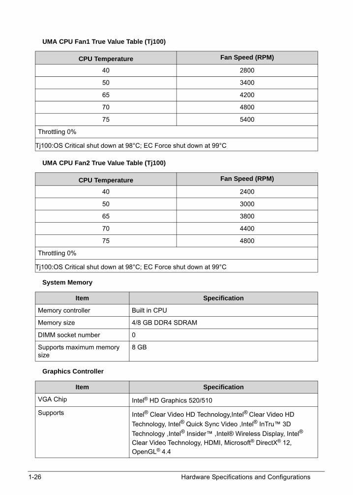
UMA CPU Fan1 True Value Table (Tj100)
UMA CPU Fan2 True Value Table (Tj100)
System Memory
Graphics Controller
CPU Temperature Fan Speed (RPM)
40 2800
50 3400
65 4200
70 4800
75 5400
Throttling 0%
Tj100:OS Critical shut down at 98°C; EC Force shut down at 99°C
CPU Temperature Fan Speed (RPM)
40 2400
50 3000
65 3800
70 4400
75 4800
Throttling 0%
Tj100:OS Critical shut down at 98°C; EC Force shut down at 99°C
Item Specification
Memory controller Built in CPU
Memory size 4/8 GB DDR4 SDRAM
DIMM socket number 0
Supports maximum memory size
8 GB
Item Specification
VGA Chip Intel® HD Graphics 520/510
Supports Intel® Clear Video HD Technology,Intel® Clear Video HD
Technology, Intel® Quick Sync Video ,Intel® InTru™ 3D
Technology ,Intel® Insider™ ,Intel® Wireless Display, Intel® Clear Video Technology, HDMI, Microsoft® DirectX® 12, OpenGL® 4.4

Hardware Specifications and Configurations 1-27
BIOS
Keyboard
Package 42mm x 24mm
Interface eDP/DP/HDMI/DVI
Max Resolution (Intel® WiDi) 1080p
Sampling rate 300MHz
Item Specification
BIOS vendor Insyde
BIOS ROM type WINBOND/W25Q128FVSIQ
BIOS ROM size 16Mbit
BIOS Features Insyde code base
Flash ROM 16Mbit
Support Acer UI
Support multi-boot
Suspend to RAM (S3)/Disk (S4)
Various hotkeys for system control
DMI utility for BIOS serial number configurable/asset tag- Support PXE
Support WinFlash
System information
HDD password
Refer to Acer BIOS specification.
Item Specification
Type LV4T keyboard
Total number of keypads AR-87/GR-87/HE-87/KO-87/RU-87/TA-87/TW-87/UI-87/A1-88/BE-88/BG-88/BR-88/CF-88/DE-88/E2-88/FR-88/GE-88/HU-88/IT-88/LA-88/ND-88/NW-88/PO-88/SD-88/SF-88/SP-88/TU-88/UK-88/WB-88/JP-91 keys
Windows key Yes
Internal & external keyboard work simultaneously
Plug USB keyboard to the USB port directly: Yes
Features Embedded numeric keypad
Support independent pgdn/pgup/home/end keys
Factory configurable different languages by OEM customer
Item Specification

1-28 Hardware Specifications and Configurations
Hard Disk Drive (AVL components)
Item Specification
Vendor & Model Name
TOSHIBA/THNSNK128GVN8
SK HYNIX/HFS128G39TND-N210A
LITEON/CV3-8D128
Capacity (GB) 128 128 128
Physical bytes per sector
512
Drive Format
Height x Width x Length(mm)
2.23x22.00x80.00 2.23x22.00x80.00 2.3x22.00x80.00
Performance Specifications
SATA revision 3.2 NA 3.0
Interface SATA SATA SATA
Fast data transfer rate (Gbits/s, max)
6.0 NA 6.0
Sequential Read (MB/s)
520 540 530
Sequential Write (MB/s)
130 130 130
DC Power Requirement
Voltage tolerance 3.3V +/- 5%
Item Specification
Vendor & Model Name
TOSHIBA/THNSNK256GVN8
SK HYNIX/HFS256G39TND-N210A
LITEON/CV3-8D256
Capacity (GB) 256 256 256
Physical bytes per sector
512
Drive Format
Height x Width x Length(mm)
2.23x22.00x80.00 2.23x22.00x80.00 2.3x22.00x80.00

Hardware Specifications and Configurations 1-29
Performance Specifications
SATA revision 3.2 NA 3.0
Interface SATA SATA
Fast data transfer rate (Gbits/s, max)
6.0 NA 6.0
Sequential Read (MB/s)
520 540 540
Sequential Write (MB/s)
250 250 170
DC Power Requirement
Voltage tolerance 3.3V +/- 5%
Item Specification
Vendor & Model Name
TOSHIBA/THNSNK512GVN8
SK HYNIX/HFS512G39TND-N210A
LITEON/CV3-8B512
Capacity (GB) 512 512 512
Physical bytes per sector
512
Drive Format
Height x Width x Length(mm)
2.23x22.00x80.00 2.23x22.00x80.00 2.3x22.00x80.00
Performance Specifications
SATA revision 3.2 NA 3.0
Interface SATA SATA SATA
Fast data transfer rate (Gbits/s, max)
6.0 NA 6.0
Sequential Read (MB/s)
520 540 520
Sequential Write (MB/s)
250 460 450
DC Power Requirement
Voltage tolerance 3.3V +/- 5%
Item Specification

1-30 Hardware Specifications and Configurations
LCD 14.0” (FHD, None Glare)
LCD 14.0” (HD, None Glare)
FHD Display Supported Resolution (System Supported Resolution)
Item Specification
Vendor/model name AUO
B140HAN02.1
INNOLUX/N140HCA-EAB
Screen Diagonal (mm) 354.69 354.69
Display resolution (pixels) 1920x3(RGB)x1080 1920x3(RGB)x1080
Pixel Pitch (mm) 0.16101(H) x 0.16101 (V) 0.1611 (H) x 0.1611 (V)
Typical White Luminance
(cd/m2) also called Brightness
220 typ., 187 min. 250 typ.
Contrast Ratio 700 : 1 700 : 1
Response Time (ms) 35 max., 30 typ. 30 max., 25typ.
Power Consumption (watt) 3.8 max. 3.24 max.
Weight(g) 270 max.(panel only) 270 max.(panel only)
Physical Size (mm) 320.9 x 205.6 x 3.0 max. 320.9 x 187.6x 3.0 max.
Electrical Interface 2 Lane eDP 1.2 2 Lane eDP 1.2
Item Specification
Vendor/model name AU
B140XTN02.E
INNOLUX/N140BGA-EA3
Screen Diagonal (mm) 354.95 354.69
Display resolution (pixels) 1366x3(RGB)x768 1366x3(RGB)x768
Pixel Pitch (mm) 0.2265(H) x 0.2265 (V) 0.2265 (H) x 0.2265 (V)
Typical White Luminance
(cd/m2) also called Brightness
220 typ., 187 min. 220 typ.
Contrast Ratio 400 : 1 500 : 1
Response Time (ms) 16 max., 8 typ. 20 max., 10 typ.
Power Consumption (watt) 2.9 max. 3.07 max.
Weight(g) 270 max.(panel only) 270 max.(panel only)
Physical Size (mm) 320.9 x 205.6 x 3.0 max. 320.9 x 187.9x 3.0 max.
Electrical Interface 1 Lane eDP 1 Lane eDP
Resolution 32bit Intel
800x600p/60Hz Y Y

Hardware Specifications and Configurations 1-31
HD Display Supported Resolution (System Supported Resolution)
Camera
Audio Codec and Amplifier
1024x768p/60Hz Y Y
1152x864/60Hz Y Y
1280x600/60Hz Y Y
1280x720/60Hz Y Y
1280x768/60Hz Y Y
1280x800/60Hz Y Y
1280x960/60Hz Y Y
1280x1024/60Hz Y Y
1360x768/60Hz Y Y
1366x768/60Hz Y Y
1440x900/60Hz Y Y
1440x1050/60Hz Y Y
1600x900/60Hz Y Y
1680x1050/60Hz Y Y
1920x1080/60Hz Y Y
Resolution 32bit Intel
800x600p/60Hz Y Y
1024x768p/60Hz Y Y
1280x600/60Hz Y Y
1280x720/60Hz Y Y
1280x768/60Hz Y Y
1360x768/60Hz Y Y
1366x768/60Hz Y Y
Item Specification
Vendor and Model CHICONY/CNFFH3521004970LH
LITEON/5SF119N2
Type 1.0M Pixels CMOS
Item Specification
Audio Controller Realtek ALC255-CGT
Resolution 32bit Intel

1-32 Hardware Specifications and Configurations
Features Meets Microsoft® WLP (Windows Logo Program) and Lync™ audio requirements for Windows systems
97dB Signal-to-Noise Ratio (A-weighting) for DAC output
90dB Signal-to-Noise Ratio (A-weighting) for ADC input
4-channel DAC supports 16/20/24-bit PCM format for independent two stereo channel or 2.1 audio playback
4-channel ADC supports 16/20/24-bit PCM format for independent two stereo channel audio input
All DACs support 44.1k/48k/96k/192kHz sample rate
All ADCs support 44.1k/48k/96k/192kHz sample rate
SPDIF-OUT supports 16/20/24-bit format and 44.1/48/88.2/96/192kHz rate
Supports MONO line level output
Analog port-E (LINE2) supports input and output re-tasking
Port-C (LINE1) and port-F (MIC2) are dedicated inputs with boost gain
Supports external PCBEEP input and features built-in digital BEEP generator
Software selectable 2.5V/3.2V/4.0V VREFOUT as bias voltage for analog microphone input
Programmable +10/+20/+30dB boost gain for analog microphone input
Supports stereo digital microphone input, and programmable boost gain and volume control
Built-in headphone amplifiers for port-E (LINE2) and port-I (HP-OUT)
Headphone amplifier for port-I does not require DC blocking capacitors
Supports three jack detection pins each designed to detect up to 2 jacks, and SPDIF-OUT jack detection
Supports combo jack with stereo headphone output and mono microphone input on a 4-pole jack
Combo jack detection without extra MOSFET needed
Supports Headset Push-Button Control for combo jack
4 GPIOs for customized applications (pin-shared with digital microphone interface and SPDIF-OUT)
Supports Anti-pop mode when analog power AVDD1 is on and DVDD/AVDD2 are off
Supports PCBEEP pass-through to Class-D output (Port D)
Supports Line-In pass-through to speaker out (Sleep & Music mode)
Volume synchronization for PCBEEP in D0/D3 mode change
PCBEEP input signal level detection
Enhanced power management features for normal operation and standby mode
Stereo Bridge-Tied Load Class-D amplifier at port-D has 2Watt (rms)/4Ω per channel output
Item Specification

Hardware Specifications and Configurations 1-33
Audio Interface
WLAN Combo Card
Features DC detector, short circuit and thermal overload protection for Class-D amplifier
Class-D amplifier has seven band hardware equalizers and high pass filter to compensate for frequency response and protect the speaker
Features AGC (Auto Gain Control) function for Class-D amplifier removes distortion when outputting high volume sound
Class-D amplifier output with slew rate control to improve EMI performance
ntel low power DCN (HDA015-B) compliant, supports power status control, jack detection, and wake-up event in D3 mode
48-pin MQFN ‘Green’ package (6x6 mm dimension)
Amplifier An integrated stereo Class-D Speaker Amplifier with 2 watt per channel output power
Item Specification
Audio Controller Realtek ALC255-CGT
Audio onboard or optional On board
Mono or Stereo Stereo and Mono
Resolution Support 16/20/24bit PCM
Compatibility Digital serial interface
Sampling rate All DACs supports 44.1k/48k/96k/192kHz sample rate
All ADCs support 44.1k/48k/96k/192kHz sample rate
Internal microphone Yes
Internal speaker/quantity Yes/(2W speaker set x2)
Item Specification
Vendor and Model FOXCONN/T77H644.01
LITEON/WCBN807A-AA
Form Factor M.2
WiFi Function
Wireless LAN Standards IEEE802.11a/b/g/n/ac standards
Operating Frequency 5GHz 802.11ac,or 2.4/5GHz 802.11n
Host Interface PCI-Express Bus interface
Bluetooth Function
Item Specification

1-34 Hardware Specifications and Configurations
Battery
USB Port
HDMI Port
Data throughput 1 Mbps (GFSK)
2 Mbps (π/4-DQPSK) for EDR
3 Mbps (8-DPSK) for EDR
Protocal Bluetooth V4.1Bluetooth V4.0 LEBluetooth V3.0+HSBluetooth V2.1+EDR
Host interface USB 2.0
Item Specifications
Vendor & Model name AC14B8K/AC14B3K
Battery Type Lithium ion
Pack capacity 3220 mAh
Number of battery cell 4
Package configuration 4S1P
Item Specification
USB compliance level USB 3.0, USB 2.0
XHCI 1
Number of USB port(s) USB 3.0x2, USB 2.0x1
Location USB 3.0/Offline USB Charger one at the left side
Type C USB3.1 Gen 1+PD+DP one at the left side
USB 2.0 one at the right side
Output Current 0.5A for USB 2.0 connector
1.0A for USB 3.0 connector
3A for USB type C connector
Item Specification
Compliance level HDMI1.4b
Maximum Total Throughput 10.2Gbps
Number of HDMI port 1
Location HDMI at left side
Item Specification

Hardware Specifications and Configurations 1-35
AC Adapter
System Power Management
Item Specification
Vendor & Model Name DELTA/ADP-45HE BB
LITEON/PA-1450-26AC
Power 45W
Input rating 90~264VAC, Voltage range
Maximum input AC current 1.2A max (at input voltage 90Vac/47Hz and maximum load)
Inrush current 264Vac, No damage; Meet fuse and bridge diode I2t de-rating
Efficiency 87.73% min. at test input 115 and 230 Vac voltage.
Output Voltage range 18.55~19.95V when the load is 0A~2.37A steadily
Output current 2.37 max
Item Specification
Vendor & Model Name LITEON/PA-1450-26AC
Power 45W
Input rating 90~264VAC, Voltage range
Maximum input AC current 1.2A max (at input voltage 90Vac/60Hz and maximum load)
Inrush current 264Vac, No damage; Meet fuse and bridge diode I2t de-rating
Efficiency 87.8% min. at test input 115 and 230 Vac voltage.
Output Voltage range 18.55~19.95V when the load is 0A~2.37A steadily
Output current 2.37 max
Item Specification
Vendor & Model Name CHICONY/A045R016L
Power 45W
Input rating 90~264VAC, Voltage range
Maximum input AC current 1.2A max (at input voltage 90Vac/60Hz and maximum load)
Inrush current 264Vac, No damage; Meet fuse and bridge diode I2t de-rating
Efficiency 87.8% min. at test input 115 Vac voltage.
86.2% min. at test input 230 Vac voltage.
Output Voltage range 18.05~19.95V when the load is 0A~2.37A steadily
Output current 2.37 max
Item Specification
Mech. Off (G3) All devices in the system are turned off completely.

1-36 Hardware Specifications and Configurations
Card Reader
System LED Indicator
Soft Off (G2/S5) OS initiated shutdown. All devices in the system are turned off completely.
Working (G0/S0) Individual devices like CPU and hard disc can be power managed.
Suspend to RAM (S3) CPU set power down, Audio, Power Down, Hard Disk Power Down.
Save to Disk (S4) Also called Hibernation Mode. System saves all system states and data onto the disc prior to power off the whole system.
Item Specification
Chipset RealtekRT/RTS5170-GRT
Package 24-pin QFN
Type non-Push
Maximum supported size Support SDXC and MSXC up to 2TB
Features Support the following memory card interfaces:
-Secure DigitalTM(SD), MultiMediaCardTM(MMC), SDHC, SDXC, Mini-SD, Micro-SD (T-flash),RS-MMC, Mobile-MMC, MMCPlus and MMC-micro
Memory StickTM(MS), Memory Stick PROTM(MS-PRO), MS Duo, MS-PRO Duo and Micro-MS (M2)
-MSPRO-HG Duo 8-bit mode
-xD-Picture CardTM (xD) including Type M, Type M+ and Type H
Item Specification
Power indicator Blue color steady on: System on
Blue color and Orange color off: System off
Orange color breeze: S3 state(LED on/off = 1S/3S)
Charge indicator Orange steady on - the computer is charging and plugged in(electricity: 0% ~ 98%)
Blue color steady on - the computer is fully charged and plugged in or plugged in (electricity: 9% ~ 100%)
Orange breeze (LED on/off = 1S/3S)- The computer is at low power and plugged in.(electricity: less than 10% battery)
Orange blink (LED on/off = 1S/1S)- The computer is at low power and un-plugged.(electricity: less than 3% battery) or abnormal.
Item Specification
Hardware Specifications and Configurations 1-37
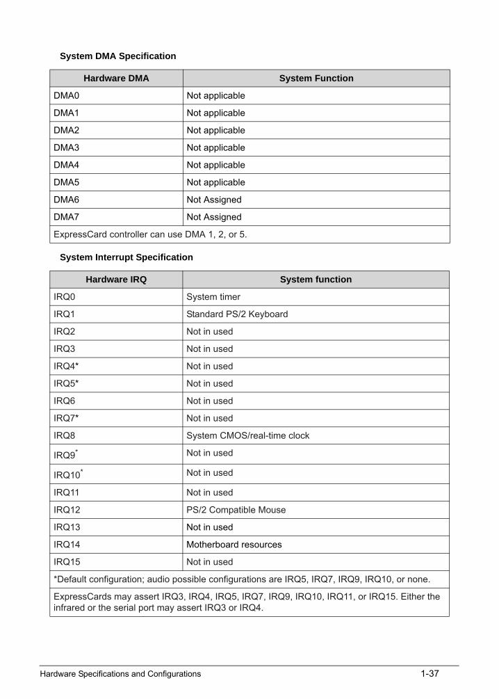
System DMA Specification
System Interrupt Specification
Hardware DMA System Function
DMA0 Not applicable
DMA1 Not applicable
DMA2 Not applicable
DMA3 Not applicable
DMA4 Not applicable
DMA5 Not applicable
DMA6 Not Assigned
DMA7 Not Assigned
ExpressCard controller can use DMA 1, 2, or 5.
Hardware IRQ System function
IRQ0 System timer
IRQ1 Standard PS/2 Keyboard
IRQ2 Not in used
IRQ3 Not in used
IRQ4* Not in used
IRQ5* Not in used
IRQ6 Not in used
IRQ7* Not in used
IRQ8 System CMOS/real-time clock
IRQ9* Not in used
IRQ10* Not in used
IRQ11 Not in used
IRQ12 PS/2 Compatible Mouse
IRQ13 Not in used
IRQ14 Motherboard resources
IRQ15 Not in used
*Default configuration; audio possible configurations are IRQ5, IRQ7, IRQ9, IRQ10, or none.
ExpressCards may assert IRQ3, IRQ4, IRQ5, IRQ7, IRQ9, IRQ10, IRQ11, or IRQ15. Either the infrared or the serial port may assert IRQ3 or IRQ4.

1-38 Hardware Specifications and Configurations
System IO Address Map
I/O address (hex) System Function (shipping configuration)
000 - CF7 PCI Express Root Complex
020 - 021 Programmable interrupt controller
024 - 025 Programmable interrupt controller
028 - 029 Programmable interrupt controller
02C - 02D Programmable interrupt controller
02E - 02F Motherboard resources
030 - 031 Programmable interrupt controller
034 - 035 Programmable interrupt controller
038 - 039 Programmable interrupt controller
03C - 03D Programmable interrupt controller
040 - 043 System timer
04E - 04F Motherboard resources
050 - 053 System timer
060 Standard PS/2 Keyboard
061 Motherboard resources
062 Microsoft ACPI-Compliant Embedded Controller
063 Motherboard resources
064 Standard PS/2 Keyboard
065 Motherboard resources
066 Microsoft ACPI-Compliant Embedded Controller
067 Motherboard resources
070 Motherboard resources
070 - 077 System CMOS/real time clock
080 Motherboard resources
092 Motherboard resources
0A0 - 0A1 Programmable interrupt controller
0A4 - 0A5 Programmable interrupt controller
0A8 - 0A9 Programmable interrupt controller
0AC - 0AD Programmable interrupt controller
0B0 - 0B1 Programmable interrupt controller
0B2 - 0B3 Motherboard resources
0B4 - 0B5 Programmable interrupt controller
0B8 - 0B9 Programmable interrupt controller

Hardware Specifications and Configurations 1-39
0BC - 0BD Programmable interrupt controller
4D0 - 4D1 Programmable interrupt controller
680 - 69F Motherboard resources
0D00 - FFFF PCI Express Root Complex
1800 - 18FE Motherboard resources
1854 - 1857 Motherboard resources
2000 - 20FE Motherboard resources
3000 - 303F Intel(R) HD Graphics 520
3040 - 305F Intel(R) 100 Series Chipset Family SMBUS - 9D23
3060 - 307F Intel(R) 6th Generation Core Processor Family Platform I/O SATA AHCI Controller
3080 - 3087 Intel(R) 6th Generation Core Processor Family Platform I/O SATA AHCI Controller
3088 - 308B Intel(R) 6th Generation Core Processor Family Platform I/O SATA AHCI Controller
FFFF - FFFF Motherboard resources
I/O address (hex) System Function (shipping configuration)

1-40 Hardware Specifications and Configurations

CHAPTER 2System Utilities

2-2
BIOS Setup Utility. . . . . . . . . . . . . . . . . . . . . . . . . . . . . . . . . . . . . 2-3Navigating the BIOS Utility . . . . . . . . . . . . . . . . . . . . . . . . . . .2-3
BIOS . . . . . . . . . . . . . . . . . . . . . . . . . . . . . . . . . . . . . . . . . . . . . . . 2-4Information. . . . . . . . . . . . . . . . . . . . . . . . . . . . . . . . . . . . . . . .2-4Main . . . . . . . . . . . . . . . . . . . . . . . . . . . . . . . . . . . . . . . . . . . . .2-5Advanced . . . . . . . . . . . . . . . . . . . . . . . . . . . . . . . . . . . . . . . . .2-7Security . . . . . . . . . . . . . . . . . . . . . . . . . . . . . . . . . . . . . . . . . . .2-9Boot. . . . . . . . . . . . . . . . . . . . . . . . . . . . . . . . . . . . . . . . . . . . . .2-14Exit. . . . . . . . . . . . . . . . . . . . . . . . . . . . . . . . . . . . . . . . . . . . . . .2-15
BIOS Flash Utilities . . . . . . . . . . . . . . . . . . . . . . . . . . . . . . . . . . . . 2-16WinFlash Utility . . . . . . . . . . . . . . . . . . . . . . . . . . . . . . . . . . . .2-17
Remove HDD/BIOS Password Utilities. . . . . . . . . . . . . . . . . . . . . 2-19Remove HDD Password Utilities . . . . . . . . . . . . . . . . . . . . . . .2-19Cleaning BIOS Passwords . . . . . . . . . . . . . . . . . . . . . . . . . . . . .2-21
Using DMI Tools . . . . . . . . . . . . . . . . . . . . . . . . . . . . . . . . . . . . . . 2-23Update Manufacture Name. . . . . . . . . . . . . . . . . . . . . . . . . . .2-23Update Product Name . . . . . . . . . . . . . . . . . . . . . . . . . . . . . . .2-26Update Serial Number . . . . . . . . . . . . . . . . . . . . . . . . . . . . . . .2-29Update Motherboard Serial Number . . . . . . . . . . . . . . . . . . .2-32Update UUID. . . . . . . . . . . . . . . . . . . . . . . . . . . . . . . . . . . . . . .2-35Update Asset Tag . . . . . . . . . . . . . . . . . . . . . . . . . . . . . . . . . . .2-40Crisis Disk Utility . . . . . . . . . . . . . . . . . . . . . . . . . . . . . . . . . . . .2-44

System Utilities 2-3
System Utilities
BIOS Setup Utility 0
A hardware configuration program built into a computer’s BIOS (Basic Input/Output System).
Preconfigured and optimized so users do not need to run this utility. If configuration problems occur, users may need to run Setup. Refer to Chapter 4, Troubleshooting when problem arises.
To activate the BIOS Utility, press F2 during POST when prompted at the bottom of screen.
The default parameter of F12 Boot Menu is set to disabled. To change boot device without entering BIOS Setup Utility, set the parameter to enabled.
To change boot device without entering the BIOS SETUP, Press <F12> during POST to enter multi-boot menu.
Navigating the BIOS Utility 0
Five menu options are:
Information
Main
Security
Boot
Exit
To navigate through the following:
Menu - use the left and right arrow keys
Item - use the up and down arrow keys
Change parameter value - press F5 or F6.
Exit - Press Esc
Load default settings - press F9. Press F10 to save changes and exit BIOS Setup Utility
NOTE:NOTE:Parameter values can be changed if enclosed in square brackets [ ]. Navigation keys appear at the bottom of the screen. Read parameter help carefully when making changes to parameter values. Parameter help is found in the Item Specific Help area of the screen. System information is subject to specific models.

2-4 System Utilities
BIOS 0
The following is a description of the tabs found on the InsydeH20 Setup Utility screen:
NOTE:NOTE:The screens provided are for reference only. Actual values may differ by model.
Information 0
This tab shows a summary of computer hardware information.
Figure 2-1. BIOS Information
Table 2-1 describes the parameters shown in Figure 2-1
Table 2-1. Parameters
Parameter Description
CPU Info The CPU type and speed of the system.
System BIOS Version
Displays system BIOS version.
GOP Version Displays version of Intel GOP Driver
HDD Model Name The model name of HDD installed.
HDD Serial Number The serial number of HDD installed.
SATA Mode Displays SATA Mode.
Total Memory Displays total memory.
Serial Number The serial number of this unit.
Asset Tag Number The asset tag number of the system.
Product Name The product name of the system.
Manufacturer Name The manufacturer Name of the system
UUID Universally Unique Identifier (UUID) is an identifier standard used in software construction, standardized by the Open Software Foundation (OSF) as part of the Distributed Computing Environment (DCE).

System Utilities 2-5
Main 0
This tab allows the user to set system time and date, enable or disable boot option and enable or disable recovery.
Figure 2-2. BIOS Main
Table 2-2 describes the parameters shown in Figure 2-2.
Table 2-2. BIOS Main
Parameter Description Format/Option
System Time
Sets the system time. The hours are shown with 24-hour format.
Format: HH:MM:SS (hour:minute:second)
System Date
Sets the system date. Format MM/DD/YYYY (month/day/year)
Network Boot
Enables, disables the system boot from LAN (remote server).
Enabled or Disabled
F12 Boot Menu
Enables, disables Boot Menu during POST. Enabled or Disabled
Touchpad Select touchpad mode Basic or Advanced
Lid Open Resume
Enables, disables system resume from S3 state by Lid open
Enabled or Disabled
D2D Recovery
Enables, disables Disk to Disk recovery. Enabled or Disabled
GPT Partition Recovery
Select GPT partition recovery mode. None, Save or Restore

2-6 System Utilities
GPT Partition Record
Display GPT Partition Record. N/A
Table 2-2. (Continued)BIOS Main
Parameter Description Format/Option

System Utilities 2-7
Advanced 0
This tab allows the user to enable or disable some system features.
Figure 2-3. BIOS Advanced
Table 2-3 describes the parameters shown in Figure 2-3.
Table 2-3. BIOS Advanced
Parameter Description Format/Option
Wi-Fi Set Wi-Fi enable or disable. Enabled or Disabled
Bluetooth Set Bluetooth enable or disable. Enabled or Disabled
Card Reader
Set Card Reader enable or disable. Enabled or Disabled
USB Ports Set USB Ports enable or disable. Enabled or Disabled
Audio Set Audio enable or disable. Enabled or Disabled
Camera Set Camera enable or disable. Enabled or Disabled
Fingerprint Set Fingerprint enable or disable. Enabled or Disabled
Type C Set Type C port enable or disable. Enabled or Disabled
Power-off Usb Charge
Set Power-off Usb Charge enable or disable. Enabled or Disabled
Battery Threshold
Set a computer battery charge limit, below which charging stops.
10% or 20% or 30%
USB Boot Set USB Boot enable or disable. Enabled or Disabled

2-8 System Utilities
Disk Sanitizer
Do disk sanitizer option. N/A
Table 2-3. (Continued)BIOS Advanced
Parameter Description Format/Option
System Utilities 2-9
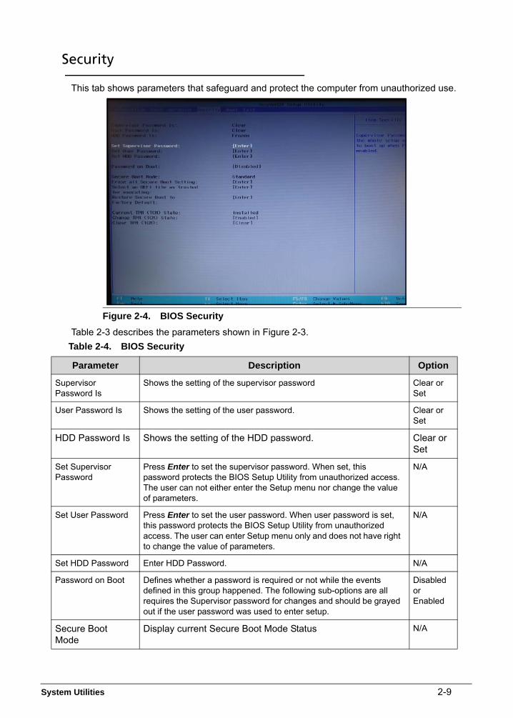
Security 0
This tab shows parameters that safeguard and protect the computer from unauthorized use.
Figure 2-4. BIOS Security
Table 2-3 describes the parameters shown in Figure 2-3.
Table 2-4. BIOS Security
Parameter Description Option
Supervisor Password Is
Shows the setting of the supervisor password Clear or Set
User Password Is Shows the setting of the user password. Clear or Set
HDD Password Is Shows the setting of the HDD password. Clear or Set
Set Supervisor Password
Press Enter to set the supervisor password. When set, this password protects the BIOS Setup Utility from unauthorized access. The user can not either enter the Setup menu nor change the value of parameters.
N/A
Set User Password Press Enter to set the user password. When user password is set, this password protects the BIOS Setup Utility from unauthorized access. The user can enter Setup menu only and does not have right to change the value of parameters.
N/A
Set HDD Password Enter HDD Password. N/A
Password on Boot Defines whether a password is required or not while the events defined in this group happened. The following sub-options are all requires the Supervisor password for changes and should be grayed out if the user password was used to enter setup.
Disabled or Enabled
Secure Boot Mode
Display current Secure Boot Mode Status N/A

2-10 System Utilities
Setting a Password 0
Perform the following to set the user or supervisor password:
1. Use the and keys to highlight the Set Supervisor Password parameter and press Enter key. The Set Supervisor Password box appears.
Figure 2-5. Set Supervisor Password
2. Type a new password in the Enter New Password field. Password length is not to exceed 8 alphanumeric characters (A-Z, a-z, 0-9, not case sensitive). Retype the password in the Confirm New Password field.
IMPORTANT:+Use care when typing a password. Characters do not appear on the screen.
3. Press Enter. After setting the password, the computer sets the User Password parameter to Set.
NOTE:NOTE:Users can opt to enable the Password on boot parameter.
4. Press F10 to save changes and exit the BIOS Setup Utility.
Erase all Secure Boot Setting
Press Enter to erase all secure boot setting. N/A
Select an UEFI file as trusted for executing
Press Enter to select an UEFI file as trusted for executing. N/A
Restore Secure Boot to Factory Default
Press Enter to restore secure boot options to factory default. N/A
Current TPM (TCM) State
Display Current TPM State N/A
Change TPM (TCM) State
Enable or disable storage and endorsement hierarchy Enable or Disable
Clear TPM (TCM) Clear TPM Clear
NOTE:When prompted to enter a password, three attempts are allowed before the system halts. Resetting the BIOS password may require the computer be returned to the dealer.
Table 2-4. BIOS Security (Continued)
Parameter Description Option

System Utilities 2-11
Removing a Password 0
Perform the following:
1. Use the and keys to highlight Set Supervisor Password and press Enter. The Set Supervisor Password box appears:
Figure 2-6. Set Supervisor Password
2. Type the current password in the Enter Current Password field and press Enter.
3. Press Enter twice without typing anything in the Enter New Password and Confirm New Password fields. The computer then sets the Supervisor Password parameter to Clear.
4. Press F10 to save changes and exit the BIOS Setup Utility.

2-12 System Utilities
Changing a Password 0
1. Use the and keys to highlight Set Supervisor Password and press the Enter. The Set Supervisor Password box appears.
Figure 2-7. Set Supervisor Password
2. Type the current password in the Enter Current Password field and press Enter.
3. Type a password in the Enter New Password field. Retype the password in the Confirm New Password field.
Figure 2-8. Setup Notice
4. Press Enter. The computer sets User Password parameter to Set.
NOTE:NOTE:Users can enable the Password on boot parameter.
5. Press F10 to save changes and exit the BIOS Setup Utility.
If the verification is OK, the screen will show as following.
Figure 2-9. This Setup Warning
The password setting is complete after the user presses Enter.
If the current password entered does not match the actual current password, the screen will show the Setup Warning (Figure 2-9).

System Utilities 2-13
Figure 2-10. Setup Warning

2-14 System Utilities
Boot 0
This tab allows changes to the order of boot devices used to load the operating system. Bootable devices include the:
USB diskette drives
Onboard hard disk drive
DVD drive in the module bay
Use and keys to select a device and press F5 or F6 to move it up or down the list.
Figure 2-11. BIOS Boot

System Utilities 2-15
Exit 0
The Exit tab allows users to save or discard changes and quit the BIOS Utility.
Figure 2-12. BIOS Exit
Table 2-4 describes the parameters in Figure 2-11.
Table 2-5. Exit Parameters
Parameter Description
Exit Saving Changes Exit System Setup and save changes to the system.
Exit Discarding Changes Exit utility without saving setup data to.
Load Setup Default Load default values for all setup item.

2-16 System Utilities
BIOS Flash Utilities 0
BIOS Flash memory updates are required for the following conditions:
New versions of system programs
New features or options
Restore a BIOS when it becomes corrupted.
Use the Flash utility to update the system BIOS Flash ROM.
NOTE:NOTE:Do not install memory related drivers (XMS, EMS, DPMI) when the Flash is used.
NOTE:NOTE:Use the AC adaptor power supply when running the Flash utility. If battery pack does not contain power to finish loading of the BIOS Flash, do not boot the system.

System Utilities 2-17
WinFlash Utility 0
Perform the following to use the WinFlash Utility:
1. Double click the flash tool (an executable file).
Figure 2-13. WinFlash executable
2. Click OK to begin the update. A progress screen is shown (Figure 2-14).
Figure 2-14. InsydeFlash

2-18 System Utilities
3. Computer will restart and update the BIOS.
Figure 2-15. BIOS Update
NOTE:NOTE:If AC power is not connected, the following message is shown.
Figure 2-16. AC Power Warning
NOTE:NOTE:Plug in the AC power to continue.
4. Flash is complete when the message update progress 100% is shown and then loading in Windows.

System Utilities 2-19
Remove HDD/BIOS Password Utilities 0
This section provides details for removing HDD/BIOS passwords.
Remove HDD Password Utilities 0
This section provides details for removing HDD passwords.
Remove HDD Password as follows:
NOTE:NOTE:If the HDD password is incorrectly entered three times, an error is generated, you will see below menu (Figure 2-17).
Figure 2-17. HDD Security
To reset the HDD password, perform the followings:
1. Select Enter Unlock Password option.
Figure 2-18. Select Item
NOTE:NOTE:An Encode key is generated for unlocking utilities. Make note for this key.
Figure 2-19. Unlock Password
2. Running the UnlockHD.exe in a bootable USB flash disk (with winpe4.0X64),
command: UnlockHD Key Code, as below photo, then he could get a Unlock Code.

2-20 System Utilities
Figure 2-20. Unlock Code
Example: UnlockHD 54299883
The command generates a password which can be used for unlocking the HDD.
Password: 30685279
Enter the password from the Step 1 to unlock the HDD.
Figure 2-21. Unlock Password
NOTE:NOTE:After users clearing the HDD password, HDD maybe in “Frozen” state. Please power off system. Then, power on to Win system, HDD Password will be in normal.

System Utilities 2-21
Cleaning BIOS Passwords 0
If users have set the supervisor password and forgotten it, users need cleaning BIOS passwords’ tool. If users have input wrong password for 3 times, BIOS will be locked and can’t enter BIOS setting and system.
Then users need to do as follows:
NOTE:NOTE:The method of cleaning BIOS passwords is a bit same as cleaning HDD password. But there is more one step for clearing BIOS passwords. Please get attention to the following steps.
To clear the BIOS password, perform the followings:
1. Select Enter Unlock Password option.
Figure 2-22. Select Item
NOTE:NOTE:An Encode key is generated for unlocking utilities. Make note for this key.
Figure 2-23. Unlock Password
2. Running the UnlockHD.exe in a bootable USB flash disk (with winpe4.0X64),
command: UnlockHD.exe Key Code, as below photo, then he could get a Unlock Code.

2-22 System Utilities
Figure 2-24. Type command and press enter to get the password
Example: UnlockHD 60102447
The command generates a password which can be used for unlocking the BIOS.
Password: 75860489
Enter the password from the Step 1 to unlock the BIOS.
Figure 2-25. Input sample password 75860489 to unlock.
NOTE:NOTE:After users clearing the BIOS password, computer will continue run and enter the Windows system automatically. But it doesn’t means the BIOS passwords has been cleared completely. Please do as follows.
Important: Shut down the computer, repower it and press F2 to enter BIOS settings. But users now cannot enter. It will ask users “Enter Current Password:”. And it means inputting supervisor password again. Actually the supervisor password has been changed to the unlock password through input Unlock Code with the use of UnlockHD.exe tool. At this time, users need to use the unlocked password that has got before now. (Refer to Figure 2-23 eg. 75860489). After that, please remove password according to page 2-10.
Figure 2-26. Input sample password 75860489 which got by step2 to unlock.

System Utilities 2-23
Using DMI Tools 0
The DMI (Desktop Management Interface) Tool copies BIOS information to EEPROM. Used in the DMI pool for hardware management.
NOTE:NOTE:Running the DMI tools in a bootable USB flash disk with winpe4.0X64 mode.
Figure 2-27. DMI Tools
Update Manufacture Name 0
1. Execute <DMI.EXE /Rm> to read Manufacturer Name(Figure 2-26 & Figure2-27).
Figure 2-28. Read Manufacturer Name

2-24 System Utilities
Figure 2-29. Read Manufacturer Name
2. Execute < DMI.EXE /Wm> to write new Manufacturer Name(Figure 2-28 to Figure 2-30).
Figure 2-30. Write Manufacturer Name

System Utilities 2-25
Figure 2-31. Write Manufacturer Name
Figure 2-32. Write Manufacturer Name

2-26 System Utilities
Figure 2-33. Write Manufacturer Name
Update Product Name 0
1. Execute < DMI.EXE /Rp> to Read Product Name(Figure 2-32 & Figure 2-33).
Figure 2-34. Read Product Name

System Utilities 2-27
Figure 2-35. Read Product Name
2. Execute < DMI.EXE /Wp> to write Product Name(Figure 2-34 to Figure 2-37).
Figure 2-36. Write Product Name

2-28 System Utilities
Figure 2-37. Write Product Name
Figure 2-38. Write Product Name

System Utilities 2-29
Figure 2-39. Write Product Name
Update Serial Number 0
1. Execute < DMI.EXE /Rfgsn> to read F/G Serial Number(Figure 2-38 & Figure 2-39).
Figure 2-40. Read Serial Number

2-30 System Utilities
Figure 2-41. Read Serial Number
2. Execute < DMI.EXE /Wfgsn> to write F/G Serial Number(Figure 2-40 & Figure 2-43).
Figure 2-42. Write Serial Number

System Utilities 2-31
Figure 2-43. Write Serial Number
Figure 2-44. Write Serial Number

2-32 System Utilities
Figure 2-45. Write Serial Number
Update Motherboard Serial Number 0
1. Execute < DMI.EXE /Rmbsn> to read Motherboard Serial Number(Figure 2-44 & Figure 2-45).
Figure 2-46. Read Motherboard Serial Number

System Utilities 2-33
Figure 2-47. Read Motherboard Serial Number
2. Execute < DMI.EXE /Wmbsn> to write Motherboard Serial Number(Figure 2-45 to Figure 2-48).
Figure 2-48. Write Motherboard Serial Number

2-34 System Utilities
Figure 2-49. Write Motherboard Serial Number
Figure 2-50. Write Motherboard Serial Number

System Utilities 2-35
Figure 2-51. Write Motherboard Serial Number
Update UUID 0
1. Execute < DMI.EXE /RUUID> to read UUID(Figure 2-50 & Figure 2-51).
Figure 2-52. Read UUID

2-36 System Utilities
Figure 2-53. Read UUID
2. Execute < DMI.EXE /GUUID> to generate and write the UUID(Figure 2-52 & Figure 2-55).
Figure 2-54. Generate and Write UUID

System Utilities 2-37
Figure 2-55. Generate and Write UUID
Figure 2-56. Generate and Write UUID

2-38 System Utilities
Figure 2-57. Generate and Write UUID
3. Execute < DMI.EXE /WUUID> to write UUID(Figure 2-56 & Figure 2-59).
Figure 2-58. Write UUID

System Utilities 2-39
Figure 2-59. Write UUID
Figure 2-60. Write UUID

2-40 System Utilities
Figure 2-61. Write UUID
Update Asset Tag 0
1. Execute < DMI.EXE /Rasset> to read Asset Tag (Figure 2-60 & Figure 2-61).
Figure 2-62. Read Asset Tag

System Utilities 2-41
Figure 2-63. Read Asset Tag
2. Execute < DMI.EXE /Wasset> to write Asset Tag(Figure 2-61 & Figure 2-64).
Figure 2-64. Write Asset Tag
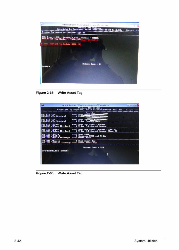
2-42 System Utilities
Figure 2-65. Write Asset Tag
Figure 2-66. Write Asset Tag

System Utilities 2-43
Figure 2-67. Write Asset Tag

2-44 System Utilities
Crisis Disk Utility 0
Crisis Disk is a BIOS recovery function, when the BIOS is damaged, users can use it to recovery the BIOS.
1. Prepare an empty USB flash disk with FAT32 format file system.
2. Copy BIOS recovery file (in the folder of crisis disk) to the root folder of the USB flash disk and make sure it is renamed to M34DA.FD.
3. Keep the adaptor inserted and do not plug it out. Shutdown the computer and plug in the USB flash disk.
4. Holding down Fn + ESC key, and power on the computer from off state.
5. After the computer is powered on, release Fn and ESC key, the system will start recovering the BIOS automatically.
6. Then computer will shutdown automatically after the recovery work is done.
7. Users can power on the computer to check whether the BIOS has been repaired.
NOTE:NOTE:The USB flash disk must be format as FAT32. Make sure it is empty before copy recovery BIOS file.
NOTE:NOTE:The crisis process will take a period of time, and system will be always no-display from the recovery work start to the end, it is a normal situation, waiting for the process is over, the power led will be off after it is over. Then users can power on the computer.

CHAPTER 3Machine Maintenance

3-2
Machine Disassembly and Replacement . . . . . . . . . . . . . . . . . 3-5Recommended Equipment . . . . . . . . . . . . . . . . . . . . . . . . . . . 3-5Replacement Requirements . . . . . . . . . . . . . . . . . . . . . . . . . . 3-5Pre-disassembly Instructions. . . . . . . . . . . . . . . . . . . . . . . . . . 3-6Disassembly Process . . . . . . . . . . . . . . . . . . . . . . . . . . . . . . . 3-7
Main Unit Disassembly Process . . . . . . . . . . . . . . . . . . . . . . . . 3-8Main Unit Disassembly Flowchart . . . . . . . . . . . . . . . . . . . . . . 3-8Removing the Bottom Cover . . . . . . . . . . . . . . . . . . . . . . . . . . 3-9Removing the Battery . . . . . . . . . . . . . . . . . . . . . . . . . . . . . . . 3-13Removing the IO Board . . . . . . . . . . . . . . . . . . . . . . . . . . . . . . 3-15Removing the Speaker . . . . . . . . . . . . . . . . . . . . . . . . . . . . . . 3-16Removing the WLAN Card . . . . . . . . . . . . . . . . . . . . . . . . . . . 3-19Removing the RTC Battery . . . . . . . . . . . . . . . . . . . . . . . . . . . 3-21Removing the Thermal Module . . . . . . . . . . . . . . . . . . . . . . . . 3-22Removing the SSD Module . . . . . . . . . . . . . . . . . . . . . . . . . . . 3-27Removing the Motherboard . . . . . . . . . . . . . . . . . . . . . . . . . . . 3-29Removing the Finger Printer Sensor . . . . . . . . . . . . . . . . . . . . 3-33Removing the LCD Module . . . . . . . . . . . . . . . . . . . . . . . . . . . 3-34Removing the Touch Pad . . . . . . . . . . . . . . . . . . . . . . . . . . . . 3-37Removing the LCD Bezel . . . . . . . . . . . . . . . . . . . . . . . . . . . . 3-39Removing the LCD Panel . . . . . . . . . . . . . . . . . . . . . . . . . . . . 3-40Removing the Hinge Cap. . . . . . . . . . . . . . . . . . . . . . . . . . . . . 3-43Removing the Camera. . . . . . . . . . . . . . . . . . . . . . . . . . . . . . . 3-45Removing the eDP Cable . . . . . . . . . . . . . . . . . . . . . . . . . . . . 3-46Removing the Hinges . . . . . . . . . . . . . . . . . . . . . . . . . . . . . . . 3-47
Main Unit Reassembly Procedure . . . . . . . . . . . . . . . . . . . . . . . 3-48Replacing the eDP Cable . . . . . . . . . . . . . . . . . . . . . . . . . . . . 3-49Replacing the Camera. . . . . . . . . . . . . . . . . . . . . . . . . . . . . . . 3-50Replacing the Hinge Cap . . . . . . . . . . . . . . . . . . . . . . . . . . . . 3-51Replacing the LCD Panel . . . . . . . . . . . . . . . . . . . . . . . . . . . . 3-52Replacing the LCD Bezel . . . . . . . . . . . . . . . . . . . . . . . . . . . . 3-54Replacing the Touch Pad . . . . . . . . . . . . . . . . . . . . . . . . . . . . 3-55Replacing the LCD Module . . . . . . . . . . . . . . . . . . . . . . . . . . . 3-56Replacing the Finger Printer Sensor . . . . . . . . . . . . . . . . . . . . 3-60Replacing the Motherboard . . . . . . . . . . . . . . . . . . . . . . . . . . . 3-61Replacing the SSD Module . . . . . . . . . . . . . . . . . . . . . . . . . . . 3-65Replacing the Thermal Module . . . . . . . . . . . . . . . . . . . . . . . . 3-67Replacing the RTC Battery . . . . . . . . . . . . . . . . . . . . . . . . . . . 3-70Replacing the WLAN Card. . . . . . . . . . . . . . . . . . . . . . . . . . . . 3-71Replacing the Speaker . . . . . . . . . . . . . . . . . . . . . . . . . . . . . . 3-73Replacing the IO Board . . . . . . . . . . . . . . . . . . . . . . . . . . . . . . 3-76

3-3
Replacing the Battery. . . . . . . . . . . . . . . . . . . . . . . . . . . . . . . 3-77Replacing the Bottom Cover . . . . . . . . . . . . . . . . . . . . . . . . . 3-78

3-4

3-5
Machine Disassembly and Replacement 0
This chapter contains step-by-step procedures on how to disassemble the notebook computer for maintenance and troubleshooting.
Cable paths and positioning may not represent the actual model. During the removal and installation of the components, ensure all available cable channels and clips are used and that the cables are replaced in the same position.
The screws for the different components vary in size. During the disassembly process, group the screws with the corresponding components to avoid mismatch when putting back the components.
The product previews seen in the disassembly procedures may not represent the final product color or configuration.
Recommended Equipment 0
To disassemble the computer, the following tools are recommended:
Wrist grounding strap and conductive mat for preventing electrostatic discharge
Flat screwdriver
Phillips screwdriver
Plastic flat screwdriver
Plastic tweezers
Replacement Requirements 0
NOTE:NOTE:Cabling and components require adhesive to be applied during the replacement and reassembly process.

3-6
Pre-disassembly Instructions 0
Before proceeding with the disassembly procedure, make sure to do the following:
1. Turn off the power to the system and all peripherals.
2. Unplug the AC adapter and all power and signal cables from the system.
Figure 3-1. AC Adapter
3. Place the system on a flat, stable surface.

3-7
Disassembly Process 0
The disassembly process is divided into the following sections:
Main unit disassembly
The flowcharts provided in the succeeding disassembly sections illustrate the entire disassembly sequence. Observe the order of the sequence to avoid damage to any of the hardware components.
Table 3-1. Main Screw List
Screw Quantity Acer Part Number
SCREW M2*3L K W-NI #1 NY 6 86.Q04N5.009
SCREW M2*2.5L(K,D4.5) B-NI,NY 4 86.VDFN5.001
SCREW M2*6.5L(K,D4.5) SW B-NI,NY
5 86.VDFN5.003
SCREW M2*4L(K,D4.5) SW B-NI,NY
4 86.VDFN5.002
SCREW M2*2L (K) B-ZN #1 NY 11 86.RYNN5.004
SCREW M2*4L (K) B-ZN #1 NY 23 86.B430U.006

3-8
Main Unit Disassembly Process 0
Main Unit Disassembly Flowchart 0
Figure 3-2. Main Unit Disassembly Flowchart
B o tto m C o ve r
B a tte ry
IO B o a rd S p e a ke r
W L A N C a rd R T C B a tte ryT h e rm a l M o d u le
S S D M o d u le M o th e r B o a rdF in g e r P rin te r
S e n so r
L C D M o d u le
T o u ch P a d L C D B e ze l
L C D P a n e l
H in g e C a p e D P ca b le C a m e ra
H in g e s
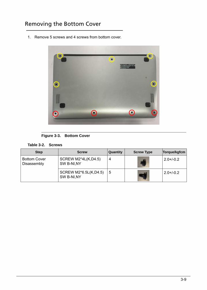
3-9
Removing the Bottom Cover 0
1. Remove 5 screws and 4 screws from bottom cover.
Figure 3-3. Bottom Cover
Table 3-2. Screws
Step Screw Quantity Screw Type Torque/kgfcm
Bottom Cover Disassembly
SCREW M2*4L(K,D4.5) SW B-NI,NY
4 2.0+/-0.2
SCREW M2*6.5L(K,D4.5) SW B-NI,NY
5 2.0+/-0.2

3-10
2. Use a plastic pry slice to insert to the gap near the middle hinge cap, pry left and right to release top edge hocks of the bottom case.
Figure 3-4. Bottom Cover
Figure 3-5. Bottom Cover
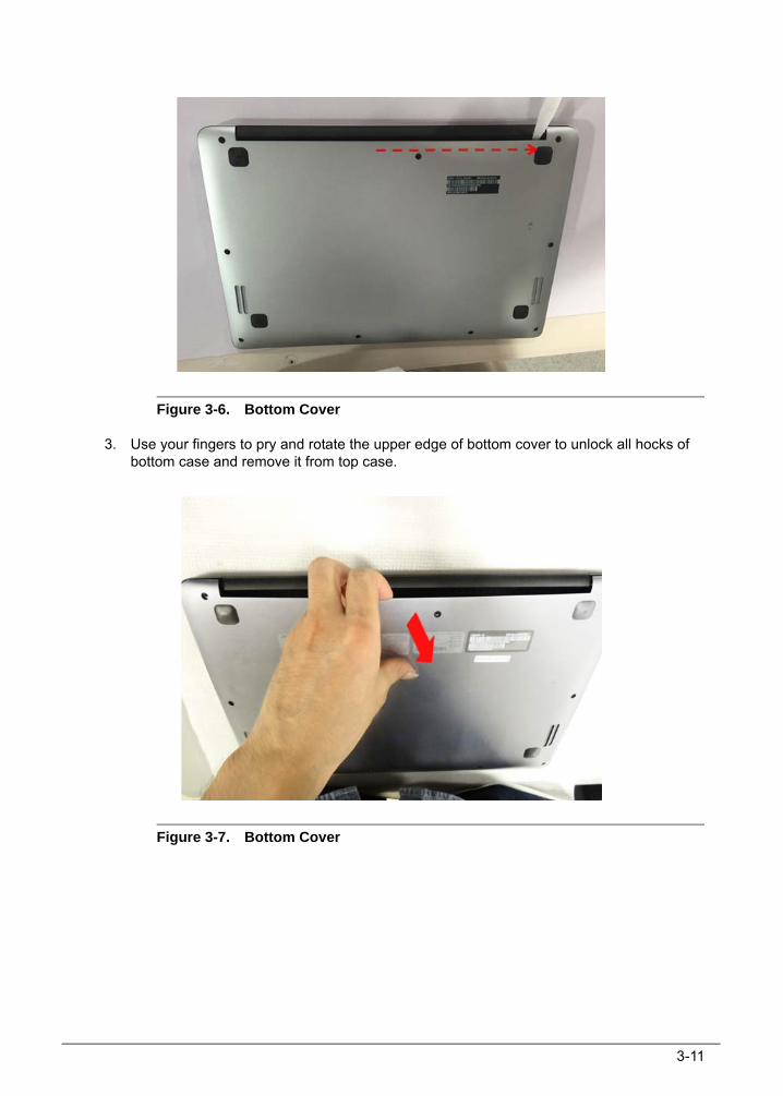
3-11
Figure 3-6. Bottom Cover
3. Use your fingers to pry and rotate the upper edge of bottom cover to unlock all hocks of bottom case and remove it from top case.
Figure 3-7. Bottom Cover

3-12
Figure 3-8. Bottom Cover

3-13
Removing the Battery 0
1. Disconnect the battery cable from main board.
Figure 3-9. Battery
2. Remove 2 screws from battery.
Figure 3-10. Battery
Table 3-3. Screws
Step Screw Quantity Screw Type Torque/kgfcm
Battery Disassembly SCREW M2*4L (K) B-NI,NY
2 2.0+/-0.2

3-14
3. Lift the battery and remove the Mylar to remove the battery.
(Note: remove the battery per WEEE directive where Annex VII)
Figure 3-11. Battery
Figure 3-12. Battery

3-15
Removing the IO Board 0
1. Disconnect the IO board FFC from the IO board and motherboard.
Figure 3-13. IO Board
2. Remove 2 screws and lift to remove the IO board.
(Note: remove the PCB its area >10cm2 per WEEE directive where Annex VII)
Figure 3-14. IO Board
Table 3-4. Screws
Step Screw Quantity Screw Type Torque/kgfcm
IO Board Disassembly SCREW M2*4L (K) B-ZN #1 NY
2 2.0+/-0.2

3-16
Removing the Speaker 0
1. Disconnect the speaker cable from the motherboard and make the cable out of its slot.
Figure 3-15. Speaker
Figure 3-16. Speaker

3-17
2. Remove 4 screws and lift to remove the speaker.
Figure 3-17. Speaker
Figure 3-18. Speaker

3-18
Figure 3-19. Speaker
Figure 3-20. Speaker
Table 3-5. Screws
Step Screw Quantity Screw Type Torque/kgfcm
Speaker Disassembly SCREW M2*2L (K) B-ZN #1 NY
4 2.0+/-0.2
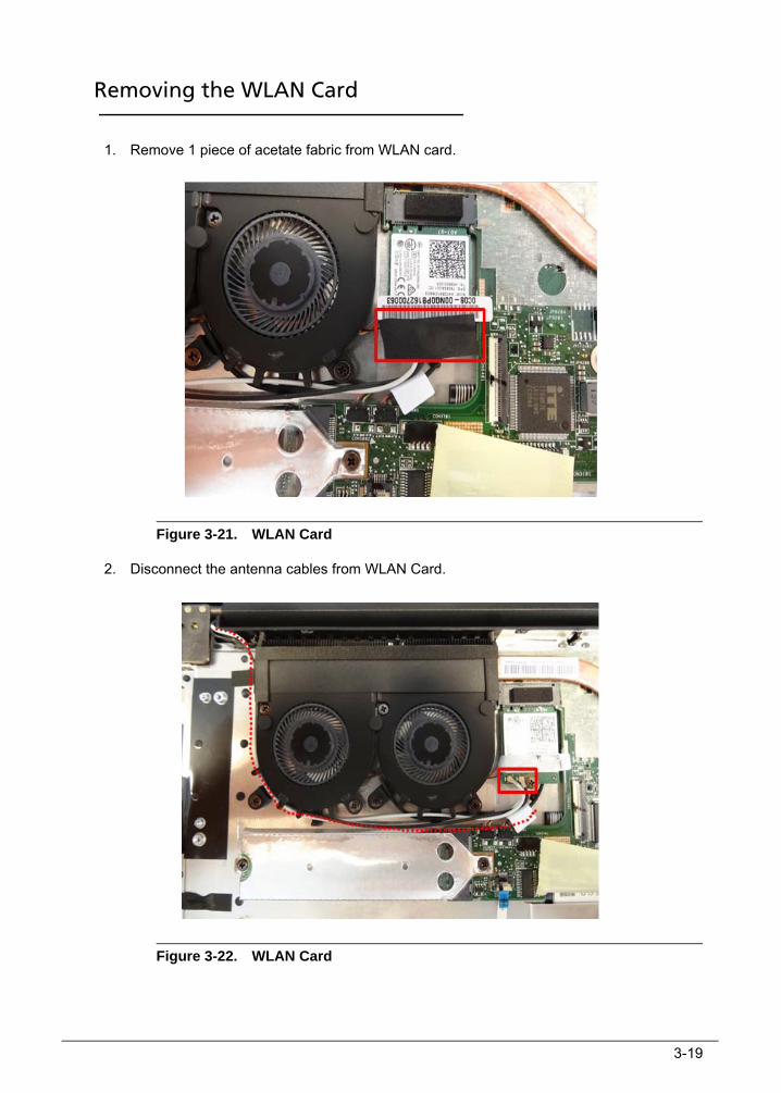
3-19
Removing the WLAN Card 0
1. Remove 1 piece of acetate fabric from WLAN card.
Figure 3-21. WLAN Card
2. Disconnect the antenna cables from WLAN Card.
Figure 3-22. WLAN Card

3-20
3. Remove 1 screw from WLAN card.
Figure 3-23. WLAN Card
Table 3-6. Screw
4. Pull out the WLAN card from the socket of main board to remove it.
Figure 3-24. WLAN Card
Step Screw Quantity Screw Type Torque/kgfcm
WLAN Card Disassembly SCREW M2*4L (K) B-ZN #1 NY
1 2.0+/-0.2

3-21
Removing the RTC Battery 0
1. Disconnect the RTC battery cable and remove the battery.
(Note: remove the battery per WEEE directive where Annex VII)
Figure 3-25. RTC Battery
Figure 3-26. RTC Battery

3-22
Removing the Thermal Module 0
1. Remove the Mylar and disconnect the eDP cable.
Figure 3-27. Thermal Module
2. Disconnect the fan cable.
Figure 3-28. Thermal Module
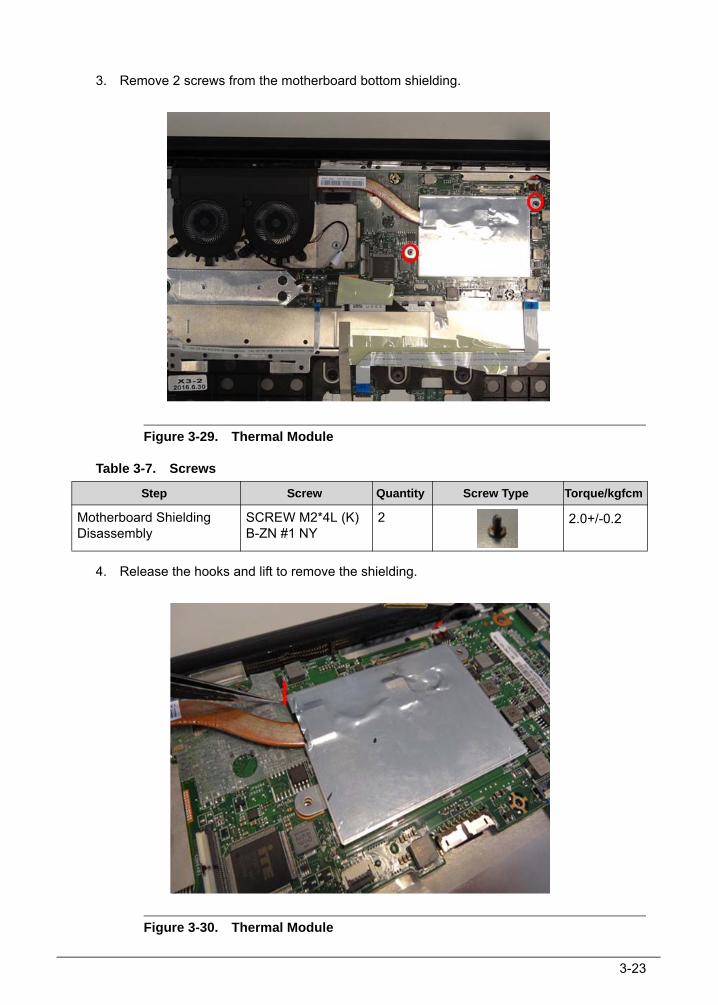
3-23
3. Remove 2 screws from the motherboard bottom shielding.
Figure 3-29. Thermal Module
Table 3-7. Screws
4. Release the hooks and lift to remove the shielding.
Figure 3-30. Thermal Module
Step Screw Quantity Screw Type Torque/kgfcm
Motherboard Shielding Disassembly
SCREW M2*4L (K) B-ZN #1 NY
2 2.0+/-0.2

3-24
Figure 3-31. Thermal Module
Figure 3-32. Thermal Module

3-25
Figure 3-33. Thermal Module
Figure 3-34. Thermal Module

3-26
5. Loose 4 screws from thermal module around CPU and remove 6 screws from fans to remove the thermal module.
Figure 3-35. Thermal Module
Figure 3-36. Thermal Module
Table 3-8. Screws
Step Screw Quantity Screw Type Torque/kgfcm
Thermal Module Disassembly
SCREW M2*4L (K) B-ZN #1 NY
6 2.0+/-0.2

3-27
Removing the SSD Module 0
1. Remove 2 screws from the SSD.
Figure 3-37. SSD Module
Table 3-9. Screws
Step Screw Quantity Screw Type Torque/kgfcm
SSD Module Disassembly SCREW M2*4L (K) B-ZN #1 NY
2 2.0+/-0.2

3-28
2. Remove the SSD AL Mylar and SSD from main board.
Figure 3-38. SSD Module
Figure 3-39. SSD Module
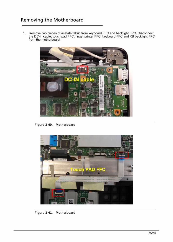
3-29
Removing the Motherboard 0
1. Remove two pieces of acetate fabric from keyboard FFC and backlight FPC. Disconnect the DC-in cable, touch pad FFC, finger printer FFC, keyboard FFC and KB backlight FPC from the motherboard.
Figure 3-40. Motherboard
Figure 3-41. Motherboard

3-30
Figure 3-42. Motherboard
Figure 3-43. Motherboard

3-31
Figure 3-44. Motherboard
2. Remove 4 screws and lift to remove the motherboard.
(Note: remove the PCB its area >10cm2 per WEEE directive where Annex VII)
Figure 3-45. Motherboard

3-32
Figure 3-46. Motherboard
Table 3-10. Screws
Step Screw Quantity Screw Type Torque/kgfcm
Motherboard Disassembly SCREW M2*4L (K) B-ZN #1 NY
4 2.0+/-0.2

3-33
Removing the Finger Printer Sensor 0
1. Remove 1 screw and lift to remove the finger printer sensor bracket.
Figure 3-47. Finger Printer Sensor
Table 3-11. Screws
2. Disconnect the finger printer sensor FFC and lift to remove the finger printer sensor.
Figure 3-48. Finger Printer Sensor
Step Screw Quantity Screw Type Torque/kgfcm
Finger Printer Sensor Disassembly
SCREW M2*4L (K) B-ZN #1 NY
1 2.0+/-0.2

3-34
Removing the LCD Module 0
1. Remove 4 screws from hinges.
Figure 3-49. LCD Module
Figure 3-50. LCD Module
Table 3-12. Screws
Step Screw Quantity Screw Type Torque/kgfcm
LCD Module Disassembly SCREW M2*4L (K) B-ZN #1 NY
4 2.0+/-0.2

3-35
2. Rotate the hinge to an approximate 90-degrees angle.
Figure 3-51. LCD Module
Figure 3-52. LCD Module

3-36
3. Lift to remove the DC-in cable.
Figure 3-53. LCD Module
4. Separate top case from LCD module.
(Note: remove the LCD panel per WEEE directive where Annex VII)
Figure 3-54. LCD Module

3-37
Removing the Touch Pad 0
1. Remove the Mylar from the touch pad.
Figure 3-55. Touch Pad
2. Remove the acetate fabric and 3 screws to remove the touch pad.
(Note: remove the PCB its area >10cm2 per WEEE directive where Annex VII)
Figure 3-56. Touch Pad

3-38
Table 3-13. Screws
Step Screw Quantity Screw Type Torque/kgfcm
Touch Pad Disassembly SCREW M2*2L (K) B-ZN #1 NY
3 2.0+/-0.2

3-39
Removing the LCD Bezel 0
NOTE:Because bezel LCD is very easy to deform, please disassemble it very carefully.
1. Use a plastic pry slice to insert to the gap between LCD bezel and LCD cover to release all latches.
Figure 3-57. LCD Bezel
2. Lift to remove the LCD bezel from LCD module.
Figure 3-58. LCD Bezel

3-40
Removing the LCD Panel 0
1. Remove 4 screws from LCD panel.
Figure 3-59. LCD Panel
Table 3-14. Screws
Step Screw Quantity Screw Type Torque/kgfcm
LCD Panel Disassembly
SCREW M2*2.5L(K,D4.5) B-NI,NY
4 2.0+/-0.2

3-41
2. Lift the upper side of LCD panel to rotate it to an approximate 130-degrees angle
Figure 3-60. LCD Panel
3. Tear off transparent tape of eDP cable from LCD panel and disconnect the eDP cable from LCD panel.
.(Note: remove the LCD panel per WEEE directive where Annex VII)
Figure 3-61. LCD Panel

3-42
Figure 3-62. LCD Panel
Figure 3-63. LCD Panel

3-43
Removing the Hinge Cap 0
1. Use a plastic pry slice to unlock all latches of hinge cap.
Figure 3-64. Hinge Cap
2. Rotate and push the hinge cap to the direction of the front to unlock all latches of hinge cap.
Figure 3-65. Hinge Cap
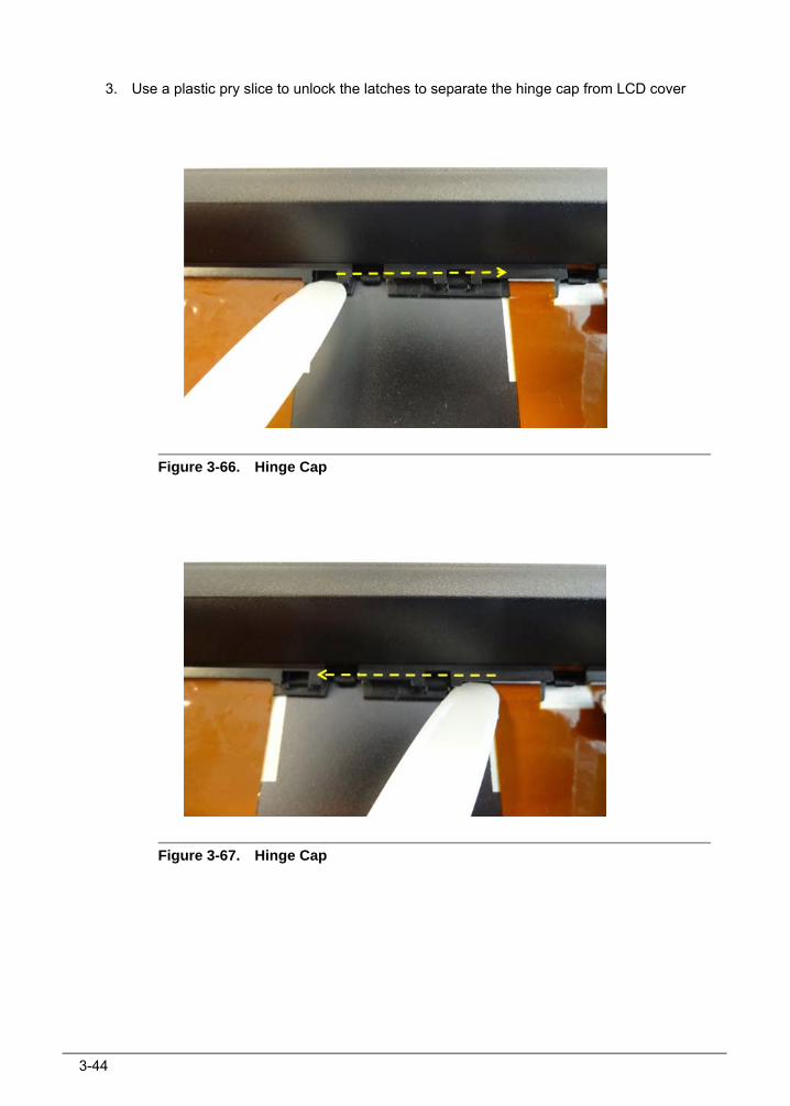
3-44
3. Use a plastic pry slice to unlock the latches to separate the hinge cap from LCD cover
Figure 3-66. Hinge Cap
Figure 3-67. Hinge Cap

3-45
Removing the Camera 0
1. Disconnect the eDP cable from camera and lift to remove the camera.
Figure 3-68. Camera

3-46
Removing the eDP Cable 0
1. Remove the acetate fabric to remove the eDP cable.
Figure 3-69. eDP Cable

3-47
Removing the Hinges 0
1. Remove the acetate fabric and 8 screws to remove hinges.
Figure 3-70. Hinge
Table 3-15. Screws
Step Screw Quantity Screw Type Torque/kgfcm
Hinge Disassembly SCREW M2*2L (K) B-ZN #1 NY
4 2.0+/-0.2
SCREW M2*4L (K) B-ZN #1 NY
4 2.0+/-0.2

3-48
Main Unit Reassembly Procedure 0
Replacing the Hinges1. Position the hinges on LCD cover, fix 8 screws and adhere1 piece of acetate fabric.
Figure 3-71. Hinge
Table 3-16. Screws
Step Screw Quantity Screw Type Torque/kgfcm
Hinge Assembly SCREW M2*2L (K) B-ZN #1 NY
4 2.0+/-0.2
SCREW M2*4L (K) B-ZN #1 NY
4 2.0+/-0.2
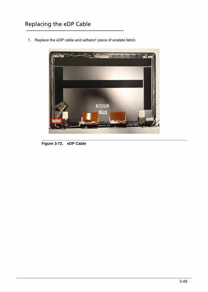
3-49
Replacing the eDP Cable 0
1. Replace the eDP cable and adhere1 piece of acetate fabric.
Figure 3-72. eDP Cable
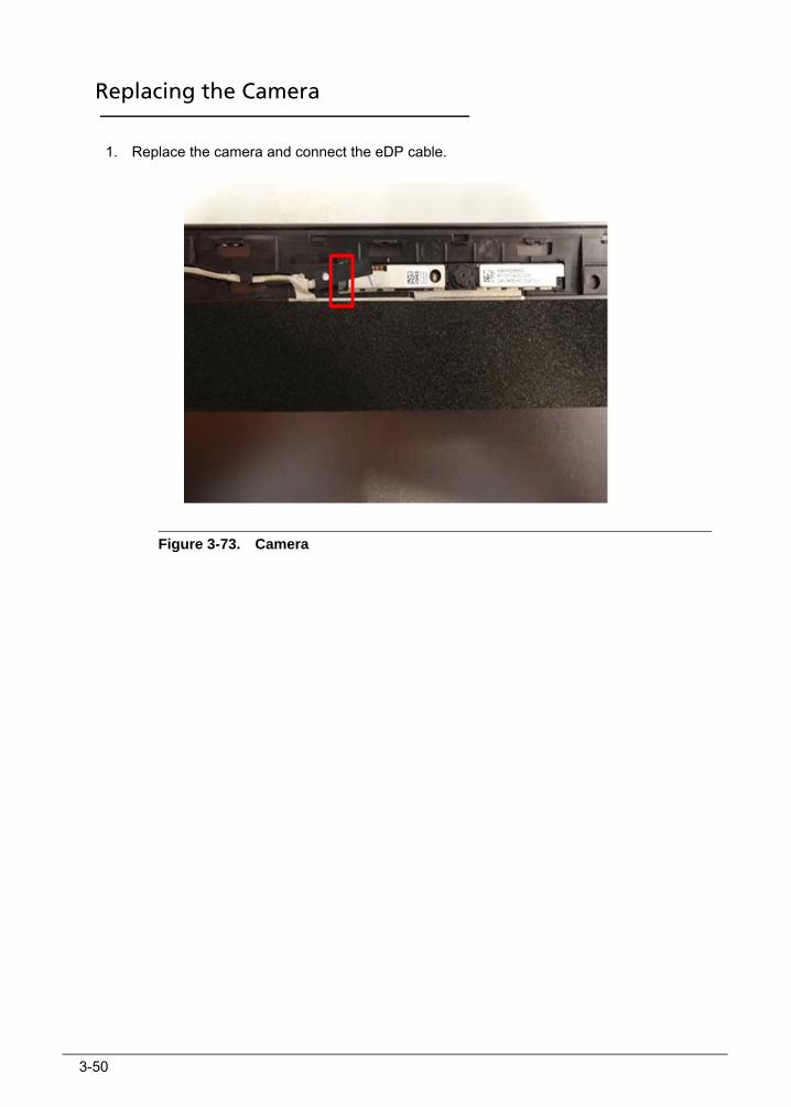
3-50
Replacing the Camera 0
1. Replace the camera and connect the eDP cable.
Figure 3-73. Camera
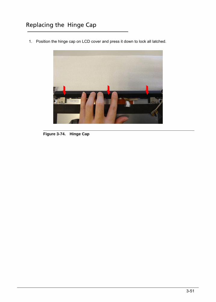
3-51
Replacing the Hinge Cap 0
1. Position the hinge cap on LCD cover and press it down to lock all latched.
Figure 3-74. Hinge Cap

3-52
Replacing the LCD Panel 0
1. Connect the eDP cable to LCD panel and adhere transparent tape of eDP cable on LCD panel.
Figure 3-75. LCD Panel
2. Lay down the LCD panel on LCD cover.
(Note: replace the LCD panel per WEEE directive where Annex VII)
Figure 3-76. LCD Panel

3-53
3. Consolidate the LCD panel with 4 screws.
Figure 3-77. LCD Panel
Table 3-17. Screws
Step Screw Quantity Screw Type Torque/kgfcm
LCD Panel Assembly
SCREW M2*2.5L(K,D4.5) B-NI,NY
4 2.0+/-0.2

3-54
Replacing the LCD Bezel 0
1. Replace the LCD bezel on LCD module and press all edges of LCD bezel to lock all latches.
Figure 3-78. LCD Bezel
Figure 3-79. LCD Bezel

3-55
Replacing the Touch Pad 0
1. Replace the touch pad, fix 3 screws and adhere the acetate fabric.
Figure 3-80. Touch Pad
Table 3-18. Screws
2. Stick the Mylar on the touch pad.
Figure 3-81. Touch Pad
Step Screw Quantity Screw Type Torque/kgfcm
Touch Pad Assembly SCREW M2*2L (K) B-ZN #1 NY
3 2.0+/-0.2

3-56
Replacing the LCD Module 0
1. Position the LCD module to the top case, then lay down it.
Figure 3-82. LCD Module
2. Replace the DC-in cable.
Figure 3-83. LCD Module

3-57
Figure 3-84. LCD Module
3. Press down the hinge to fix the top case.
Figure 3-85. LCD Module

3-58
Figure 3-86. LCD Module
4. Consolidate the hinges with 4 screws.
Figure 3-87. LCD Module

3-59
Figure 3-88. LCD Module
Table 3-19. Screws
Step Screw Quantity Screw Type Torque/kgfcm
LCD Module Assembly SCREW M2*4L (K) B-ZN #1 NY
4 2.0+/-0.2

3-60
Replacing the Finger Printer Sensor 0
1. Replace the finger printer sensor and connect the FFC.
Figure 3-89. Finger Printer Sensor
2. Replace the finger printer sensor bracket and fix 1 screw.
Figure 3-90. Finger Printer Sensor
Table 3-20. Screws
Step Screw Quantity Screw Type Torque/kgfcm
Finger Printer Sensor Assembly
SCREW M2*4L (K) B-ZN #1 NY
1 2.0+/-0.2

3-61
Replacing the Motherboard 0
1. Replace the main board to the top case.
(Note: replace the PCB its area >10cm2 per WEEE directive where Annex VII)
Figure 3-91. Motherboard
2. Consolidate motherboard with 4 screws.
Figure 3-92. Motherboard
Table 3-21. Screws
Step Screw Quantity Screw Type Torque/kgfcm
Motherboard Assembly SCREW M2*4L (K) B-NI,NY
4 2.0+/-0.2

3-62
3. Connect the keyboard FFC, KB backlight FPC, finger printer FFC, touch pad FFC and DC-in cable from the motherboard.Stick two pieces of acetate fabric on keyboard FFC and backlight FPC.
Figure 3-93. Motherboard
Figure 3-94. Motherboard

3-63
Figure 3-95. Motherboard
Figure 3-96. Motherboard

3-64
Figure 3-97. Motherboard

3-65
Replacing the SSD Module 0
1. Replace the SSD and AL Mylar.
Figure 3-98. SSD Module
Figure 3-99. SSD Module

3-66
2. Fix 2 screws from the SSD.
Figure 3-100. SSD Module
Table 3-22. Screws
Step Screw Quantity Screw Type Torque/kgfcm
SSD Module Assembly SCREW M2*4L (K) B-ZN #1 NY
2 2.0+/-0.2

3-67
Replacing the Thermal Module 0
1. Replace the thermal module and consolidate 4 screws on thermal module around CPU and fix 6 screws on fans.
Figure 3-101. Thermal Module
Figure 3-102. Thermal Module
Table 3-23. Screws
Step Screw Quantity Screw Type Torque/kgfcm
Thermal Module Assembly
SCREW M2*4L (K) B-ZN #1 NY
6 2.0+/-0.2

3-68
2. Replace the mother board bottom shielding and press to fix it.
Figure 3-103. Thermal Module
3. Fix 2 screws on the shielding.
Figure 3-104. Thermal Module
Table 3-24. Screws
Step Screw Quantity Screw Type Torque/kgfcm
Motherboard Shielding Assembly
SCREW M2*4L (K) B-ZN #1 NY
2 2.0+/-0.2

3-69
4. Connect the fan cable.
Figure 3-105. Thermal Module
5. Connect the eDP cable and stick the Mylar.
Figure 3-106. Thermal Module

3-70
Replacing the RTC Battery 0
1. Replace the RTC battery and connect the cable to motherboard.
(Note: replace the battery per WEEE directive where Annex VII)
Figure 3-107. RTC Battery
Figure 3-108. RTC Battery

3-71
Replacing the WLAN Card 0
1. Insert the WLAN card into the socket of main board.
Figure 3-109. WLAN Card
2. Consolidate WLAN card with 1 screw.
Figure 3-110. WLAN Card
Table 3-25. Screw
Step Screw Quantity Screw Type Torque/kgfcm
WLAN Card Assembly SCREW M2*4L (K) B-ZN #1 NY
1 2.0+/-0.2

3-72
3. Connect the antenna cables to WLAN Card.
Figure 3-111. WLAN Card
4. Adhere 1 piece of acetate fabric on WLAN card.
Figure 3-112. WLAN Card

3-73
Replacing the Speaker 0
1. Replace the speaker and fix 4 screws.
Figure 3-113. Speaker
Figure 3-114. Speaker

3-74
Figure 3-115. Speaker
Figure 3-116. Speaker
Table 3-26. Screws
Step Screw Quantity Screw Type Torque/kgfcm
Speaker Assembly SCREW M2*2L (K) B-ZN #1 NY
4 2.0+/-0.2

3-75
2. Connect the speaker cable to the motherboard and make the cable in its slot.
Figure 3-117. Speaker
Figure 3-118. Speaker

3-76
Replacing the IO Board 0
1. Replace the IO board and fix 2 screws.
(Note: replace the PCB its area >10cm2 per WEEE directive where Annex VII)
Figure 3-119. IO Board
Table 3-27. Screws
2. Connect the IO board FFC to the IO board and motherboard.
Figure 3-120. IO Board
Step Screw Quantity Screw Type Torque/kgfcm
IO Board Assembly SCREW M2*4L (K) B-ZN #1 NY
2 2.0+/-0.2

3-77
Replacing the Battery 0
1. Connect the battery cable and stick the Mylar.
Figure 3-121. Battery
2. Position the battery on top case and fix 2 screws.
(Note: replace the battery per WEEE directive where Annex VII)
Figure 3-122. Battery
Table 3-28. Screws
Step Screw Quantity Screw Type Torque/kgfcm
Battery Assembly SCREW M2*4L (K) B-NI,NY
2 2.0+/-0.2
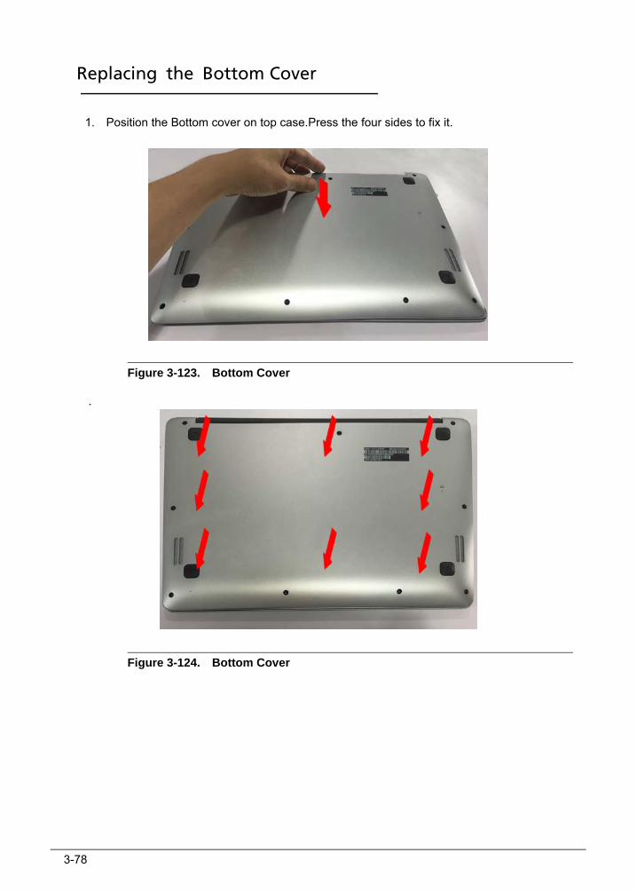
3-78
Replacing the Bottom Cover 0
1. Position the Bottom cover on top case.Press the four sides to fix it.
Figure 3-123. Bottom Cover
.
Figure 3-124. Bottom Cover

3-79
2. Consolidate bottom cover with 5 screws and 4 screws
Figure 3-125. Bottom Cover
Table 3-29. Screws
.
Step Screw Quantity Screw Type Torque/kgfcm
Bottom Cover Assembly
SCREW M2*4L(K,D4.5) SW B-NI,NY
4 2.0+/-0.2
SCREW M2*6.5L(K,D4.5) SW B-NI,NY
5 2.0+/-0.2

3-80

CHAPTER 4Troubleshooting

4-2
Introduction . . . . . . . . . . . . . . . . . . . . . . . . . . . . . . . . . . . . . . . . . 4-3General Information . . . . . . . . . . . . . . . . . . . . . . . . . . . . . . . . . . 4-3
Power On Issues . . . . . . . . . . . . . . . . . . . . . . . . . . . . . . . . . . . . .4-4No Display Issues . . . . . . . . . . . . . . . . . . . . . . . . . . . . . . . . . . . .4-5LCD Failure . . . . . . . . . . . . . . . . . . . . . . . . . . . . . . . . . . . . . . . . .4-7Keyboard Failure . . . . . . . . . . . . . . . . . . . . . . . . . . . . . . . . . . . .4-8Touchpad Failure . . . . . . . . . . . . . . . . . . . . . . . . . . . . . . . . . . . .4-9Internal & External Speaker Failure . . . . . . . . . . . . . . . . . . . . .4-10Microphone Failure . . . . . . . . . . . . . . . . . . . . . . . . . . . . . . . . . .4-12USB Failure . . . . . . . . . . . . . . . . . . . . . . . . . . . . . . . . . . . . . . . . .4-13WLAN Failure . . . . . . . . . . . . . . . . . . . . . . . . . . . . . . . . . . . . . . .4-14Card Reader Failure . . . . . . . . . . . . . . . . . . . . . . . . . . . . . . . . . .4-15Thermal Unit Failure . . . . . . . . . . . . . . . . . . . . . . . . . . . . . . . . .4-16HDMI Failure . . . . . . . . . . . . . . . . . . . . . . . . . . . . . . . . . . . . . . .4-17Other Functions Failure. . . . . . . . . . . . . . . . . . . . . . . . . . . . . . .4-18
Intermittent Problems . . . . . . . . . . . . . . . . . . . . . . . . . . . . . . . . . 4-18Undetermined Problems . . . . . . . . . . . . . . . . . . . . . . . . . . . . . . . 4-18Post Codes . . . . . . . . . . . . . . . . . . . . . . . . . . . . . . . . . . . . . . . . . . 4-19
POST Code Range. . . . . . . . . . . . . . . . . . . . . . . . . . . . . . . . . . .4-19

Troubleshooting 4-3
Troubleshooting
Introduction 0
This chapter contains information about troubleshooting common problems associated with the notebook.
General Information 0
The following procedures are a guide for troubleshooting computer problems. The step by step procedures are designed to be performed as described.
NOTE:NOTE:The diagnostic tests are intended for Acer products only. Non-Acer products, prototype cards, or modified options can give false errors and invalid system responses.
1. Obtain as much detailed information as possible about the problem.
2. If possible, verify the symptoms by re-creating the failure through diagnostic tests or repeating the operation that led to the problem.
3. Use Table 4-1 with the verified symptom to determine the solution.
4. If the Issue is still not resolved, refer to Online Support Information.
Table 4-1. Common Problems
Symptoms (Verified)
Power On Issues
No Display Issues
LCD Failure
Keyboard Failure
Touchpad Failure
Internal & External Speaker Failure
Microphone Failure
USB Failure
WLAN Failure
Card Reader Failure
Thermal Unit Failure
HDMI Failure
Other Functions Failure
Intermittent Problems
Undetermined Problems

4-4 Troubleshooting
Power On Issues 0
If the system does not power on, perform the following, one at a time, to correct the problem. Do not replace a non-defective FRU:
Figure 4-1. Power On Issue
Please wait for 3 min. after removing all power (AC adapter and Battery), then re-insert to try power on.
Computer Shuts Down Intermittently 0
If the system powers off at intervals, perform the following.
1. Makes sure the power cable is properly connected to the computer and the electrical outlet.
2. Remove all extension cables between the computer and the outlet.
3. Remove all surge protectors between the computer and the electrical outlet. Plug the computer directly into a known serviceable electrical outlet.
4. Disconnect the power and open the casing to check the Thermal Unit (refer to Thermal Unit Failure) and fan airways are free of obstructions.
5. Remove all external and non-essential hardware connected to the computer that are not necessary to boot the computer to the failure point.
6. Remove any recently installed software.
7. If the Issue is still not resolved, refer to Online Support Information.
Start
CheckAC/BatteryPower on
Check Daughter BD &
FFC
NG
OK
Swap AC/Battery
Swap Daughter BD
& Re-plug PWR FFC
NG
OK
Swap MB

Troubleshooting 4-5
No Display Issues 0
If the Display does not work, perform the following, one at a time. Do not replace a non-defective FRU:
Figure 4-2. No Display Issue
No POST or Video 0
If the POST or video does not appear, perform the following, one at a time.
1. Make sure that internal display is selected. Switching between internal and external by pressing Fn+F5. Reference Product pages for specific model procedures.
2. Make sure the computer has power by checking for one of the following:
Fans start up
Status LEDs illuminate
If no power, refer to Power On Issues.
3. Drain stored power by removing the power cable and battery. Hold the power button for 10 seconds.
4. Connect the power and reboot the computer.
START
Power On?
Ext.DDRRAM Module well connected?
Ext DDRRAM Module OK?
CPU Thermal Module well screwed?
LCD Moduel OK?
NG Power On Issue
Replace MB
NG Check Connection
NGReplace
Ext. DDRRAM Module
NG Fasten Screw
NG
Replace LCD Panel/LCD Cable

4-6 Troubleshooting
5. Connect an external monitor to the computer and switch between the internal display and the external display is by pressing Fn+F5.
6. If the POST or video appears on the external display only, refer to LCD Failure.
7. Disconnect power and all external devices including port replicators or docking stations. Remove any memory cards.
8. Start the computer. If the computer boots correctly, add the devices one by one until the failure point is discovered.
9. Re-set the memory modules.
10. Remove the drives (refer to Disassembly Process).
11. If the Issue is still not resolved, refer to Online Support Information.
Abnormal Video 0
If the video appears abnormal, perform the following, one at a time.
1. Boot the computer.
If permanent vertical/horizontal lines or dark spots appear in the same location, the LCD is faulty and should be replaced. Refer to Disassembly Process.
If extensive pixel damage is present (different colored spots in the same locations on the screen), the LCD is faulty and should be replaced. Refer to Disassembly Process.
NOTE:NOTE:Make sure that the computer is not running on battery alone as this may reduce display brightness.
2. Adjust the brightness to its highest level. Refer to the User Manual for instructions on adjusting the settings. If the display is too dim at the highest brightness setting, the LCD is faulty and should be replaced. Refer to Disassembly Process.
3. Check the display resolution is correctly configured:
Minimize or close all Windows.
If display size is only abnormal in an application, check the view settings and control/mouse wheel zoom feature in the application.
If desktop display resolution is not normal, right-click on the desktop and select Personalize Display Settings.
Click and drag the Resolution slider to the desired resolution.
Click Apply and check the display. Readjust if necessary.
4. Roll back the video driver to the previous version if updated.
5. Remove and reinstall the video driver.
6. Check the Device Manager to determine that:
The device is properly installed. There are no red Xs or yellow exclamation marks
There are no device conflicts
No hardware is listed under Other Devices
7. If the Issue is still not resolved, refer to Online Support Information.
8. Run the Windows Memory Diagnostic from the operating system DVD and follow the on-screen prompts.
9. If the Issue is still not resolved, refer to Disassembly Process.

Troubleshooting 4-7
LCD Failure 0
If the LCD fails, perform the following, one at a time. Do not replace a non-defective FRU:
Figure 4-3. LCD Failure
START
NG
NG
Swap MB
Swap LCD Module/LCD
Panel
Reassemble/Re-plug LCD Cable
Check LCDConnector/
Cable
CheckLCD Module

4-8 Troubleshooting
Keyboard Failure 0
If the Keyboard fails, perform the following, one at a time. Do not replace a non-defective FRU:
Figure 4-4. Keyboard Failure
START
NG
NG
Replace M/B
Connect it Well
Replace KeyboardKeyboard Ok?
Keyboard FFC Well Connected?

Troubleshooting 4-9
Touchpad Failure 0
If the Touchpad fails, perform the following, one at a time. Do not replace a non-defective FRU:
Figure 4-5. Touchpad Failure
START
NG
NG
Swap MB
Reassemble the T/P FFC to MB
Swap/Reassemble the T/P Pad or T/P
FFC
Check Touchpad
Check MB T/P FFC

4-10 Troubleshooting
Internal & External Speaker Failure 0
If internal Speakers fail, perform the following, one at a time. Do not replace a non-defective FRU:
Figure 4-6. Internal Speaker Failure
Sound Problems 0
Perform the following, one at a time.
1. Boot the computer.
2. Navigate to Start Control Panel System and Security System Device Manager. Check the Device Manager to determine that:
The device is properly installed
There are no red X or yellow exclamation marks
There are no device conflicts
No hardware is listed under Other Devices
3. If updated recently, roll back the audio driver to the previous version.
4. Remove and reinstall the audio driver.
5. Make sure that all volume controls are set mid range:
Click the volume icon on the task bar
Drag the slider to 50. Confirm that the volume is not muted.
START
NG
NG
Swap MB
Reassemble theSPK cable to MB
Swap ReassembleThe SPK module
Check SPKmodule
Check MBSPK cable
START
NG
NG
Swap MB
Reassemble I/O Board FPC
Swap I/O BoardCheck I/O Board OK?
Check I/O Board Connection

Troubleshooting 4-11
Click Mixer to verify that other audio applications are set to 50 and not muted.
6. Navigate to Start Control Panel Hardware and Sound Sound. Confirm that Speakers are selected as the default audio device (green check mark).
NOTE:NOTE:If Speakers do not show, right-click on the Playback tab and select Show Disabled Devices (clear by default).
7. Select Speakers and click Configure to start Speaker Setup. Follow the on-screen prompts to configure the speakers.
8. Remove any recently installed hardware or software.
9. Restore system and file settings from a known good date using System Restore.
10. If the issue is remains, repeat step 9, selecting an earlier time and date.
11. Reinstall the Operating System.
12. Connect a set of earphones or external speakers. If these function correctly, the internal speaker or I/O board may be defective. If they do not function correctly, the mother board may be defective or damaged.
13. If the Issue is still not resolved, refer to Online Support Information.

4-12 Troubleshooting
Microphone Failure 0
If internal or external Microphones fail, perform the following, one at a time.
Figure 4-7. Microphone Failure
1. Check that the microphone is enabled. Navigate to Start-> Control Panel->Hardware and Sound-> Sound and select the Recording tab.
2. Right click on the Recording tab and select Show Disabled Devices (clear by default). The microphone appears on the Recording tab.
3. Right click on the microphone and select Enable.
4. Select the microphone then click Properties. Select the Levels tab.
5. Increase the volume to the maximum setting and click OK.
6. Test the microphone hardware:
Select the microphone and click Configure.
Select Set up microphone.
Select the microphone type from the list and click Next.
Follow the on-screen prompts to complete the test.
7. If the Issue is still not resolved, refer to Online Support Information.
Start
NoCheck Mic toMB cable well connected?
Re-assemble Mic cable to MB
NoCheck Mic module?Swap Mic module
and cable
Replace M/B

Troubleshooting 4-13
USB Failure 0
If the USB fails, perform the following, one at a time. Do not replace a non-defective FRU:
Figure 4-8. USB Failure.
S ta r t
N oC h e c k U S B b o a rd toM B c a b le
R e -a s s e m b le U S B b o a rd c a b le to M B
N oC h e c k U S B b o a rd ?S w a p U S B b o a rd
a n d U S B c a b le
R e p la c e M /B

4-14 Troubleshooting
WLAN Failure 0
If the WLAN fails, perform the following, one at a time. Do not replace a non-defective FRU:
Figure 4-9. WLAN Failure
S ta r t
N oW L A N d e v ic e tu rn o n ?T u rn o n W L A N d e v ic e fro m A c e r R in g D e v ic e
C o n tro l
N oC h e c k W L A N d e v ic e O K ? R e - in s ta ll W L A N d r iv e r o r S w a p W L A N m o d u le
R e p la c e M /B
N o
C h e c k W L A N a n te n n a w e ll c o n n e c t?
N o R e -a s s e m b le W L A N a n te n n a
C h e c k W L A N a n te n n a ? N o S w a p W L A N a n te n n a
C h e c k W /L d e v ic e in s e r t w e ll?R e a s s e m b le W /L
d e v ic e

Troubleshooting 4-15
Card Reader Failure 0
If the Card Reader fails, perform the following, one at a time. Do not replace a non-defective FRU:
Figure 4-10. Card Reader Failure
The Card Reader device will disappear in device manager for power saving if there is no card inserted. Try to insert card, then the Card Reader appear in device manager.
S t a r t
R e p la c e M /B
N oC h e c k C a r d R e a d e r
d e v ic e O K ?R e - in s t a l l C a r d R e a d e r d r iv e r

4-16 Troubleshooting
Thermal Unit Failure 0
If the Thermal Unit fails, perform the following, one at a time. Do not replace a non-defective FRU:
Figure 4-11. Thermal Unit Failure
Start
Fan power wire well connected?
Fan OK?
Heatsink well seated?
CPU OK?
Replace M/B
Check ConnectNo
Replace thermal module
No
Seat it wellNo
Replace CPUNo

Troubleshooting 4-17
HDMI Failure 0
If the HDMI function fails, perform the following, one at a time. Do not replace a non-defective FRU:
Figure 4-12. HDMI Failure
START
NG
NG
Swap MB
Reinsert HDMI Connector
Reinstall corrcet driver
CheckDrivers install OK or not in Device
manager
HDMI connection check
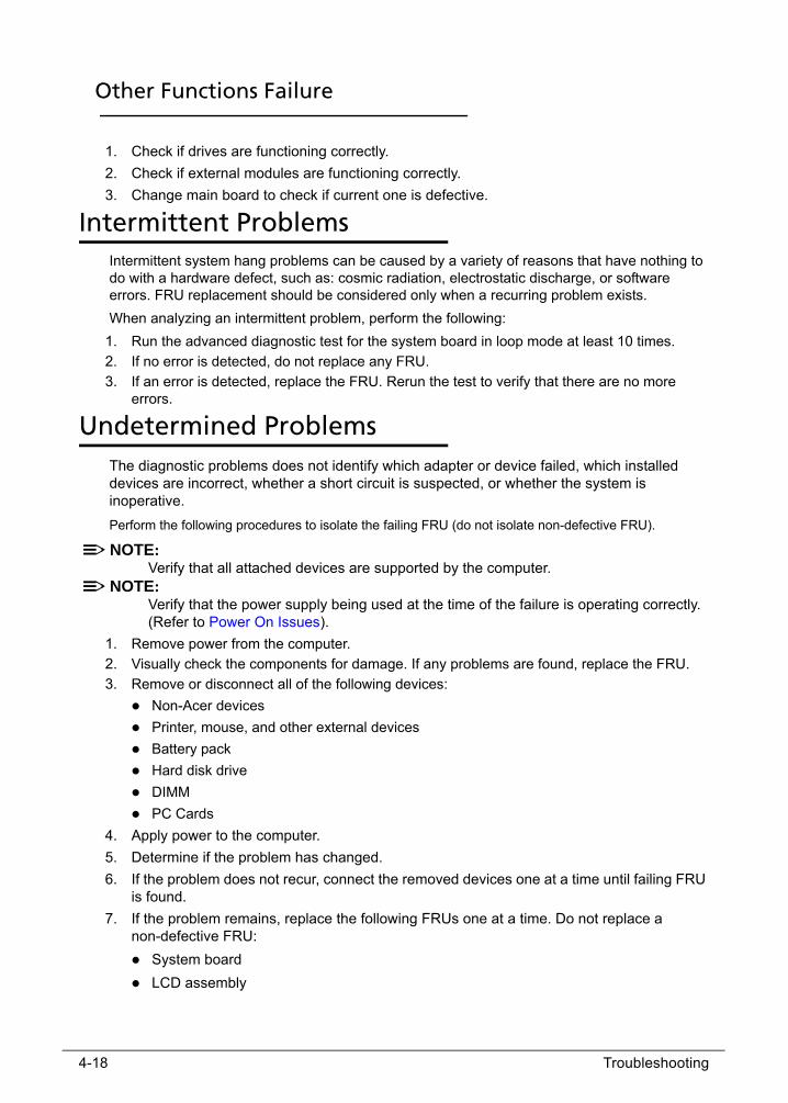
4-18 Troubleshooting
Other Functions Failure 0
1. Check if drives are functioning correctly.
2. Check if external modules are functioning correctly.
3. Change main board to check if current one is defective.
Intermittent Problems 0
Intermittent system hang problems can be caused by a variety of reasons that have nothing to do with a hardware defect, such as: cosmic radiation, electrostatic discharge, or software errors. FRU replacement should be considered only when a recurring problem exists.
When analyzing an intermittent problem, perform the following:
1. Run the advanced diagnostic test for the system board in loop mode at least 10 times.
2. If no error is detected, do not replace any FRU.
3. If an error is detected, replace the FRU. Rerun the test to verify that there are no more errors.
Undetermined Problems 0
The diagnostic problems does not identify which adapter or device failed, which installed devices are incorrect, whether a short circuit is suspected, or whether the system is inoperative.
Perform the following procedures to isolate the failing FRU (do not isolate non-defective FRU).
NOTE:NOTE:Verify that all attached devices are supported by the computer.
NOTE:NOTE:Verify that the power supply being used at the time of the failure is operating correctly. (Refer to Power On Issues).
1. Remove power from the computer.
2. Visually check the components for damage. If any problems are found, replace the FRU.
3. Remove or disconnect all of the following devices:
Non-Acer devices
Printer, mouse, and other external devices
Battery pack
Hard disk drive
DIMM
PC Cards
4. Apply power to the computer.
5. Determine if the problem has changed.
6. If the problem does not recur, connect the removed devices one at a time until failing FRU is found.
7. If the problem remains, replace the following FRUs one at a time. Do not replace a non-defective FRU:
System board
LCD assembly
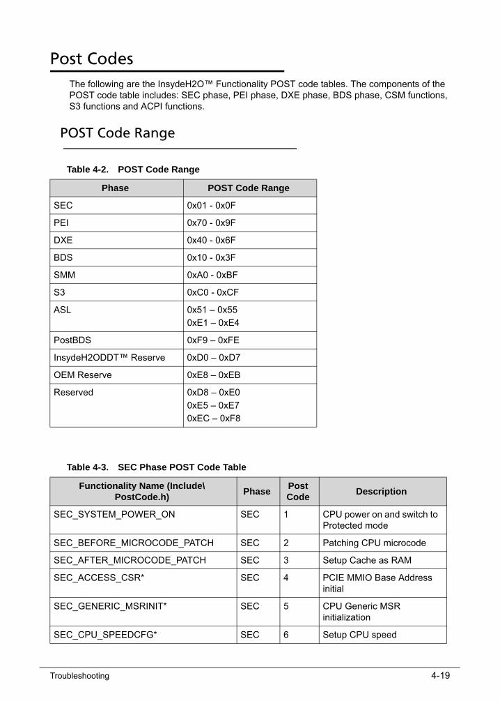
Troubleshooting 4-19
Post Codes 0
The following are the InsydeH2O™ Functionality POST code tables. The components of the POST code table includes: SEC phase, PEI phase, DXE phase, BDS phase, CSM functions, S3 functions and ACPI functions.
POST Code Range 0
Table 4-2. POST Code Range
Phase POST Code Range
SEC 0x01 - 0x0F
PEI 0x70 - 0x9F
DXE 0x40 - 0x6F
BDS 0x10 - 0x3F
SMM 0xA0 - 0xBF
S3 0xC0 - 0xCF
ASL 0x51 – 0x55
0xE1 – 0xE4
PostBDS 0xF9 – 0xFE
InsydeH2ODDT™ Reserve 0xD0 – 0xD7
OEM Reserve 0xE8 – 0xEB
Reserved 0xD8 – 0xE0
0xE5 – 0xE7
0xEC – 0xF8
Table 4-3. SEC Phase POST Code Table
Functionality Name (Include\ PostCode.h)
PhasePost Code
Description
SEC_SYSTEM_POWER_ON SEC 1 CPU power on and switch to Protected mode
SEC_BEFORE_MICROCODE_PATCH SEC 2 Patching CPU microcode
SEC_AFTER_MICROCODE_PATCH SEC 3 Setup Cache as RAM
SEC_ACCESS_CSR* SEC 4 PCIE MMIO Base Address initial
SEC_GENERIC_MSRINIT* SEC 5 CPU Generic MSR initialization
SEC_CPU_SPEEDCFG* SEC 6 Setup CPU speed

4-20 Troubleshooting
SEC_SETUP_CAR_OK SEC 7 Cache as RAM test
SEC_FORCE_MAX_RATIO* SEC 8 Tune CPU frequency ratio to maximum level
SEC_GO_TO_SECSTARTUP SEC 9 Setup BIOS ROM cache
SEC_GO_TO_PEICORE SEC 0A Enter Boot Firmware Volume
* 3rd party relate functions – Platform dependence.
Table 4-4. PEI Phase POST Code Table
Functionality Name (Include\ PostCode.h)
Phase Post Code
Description
PEI_SIO_INIT PEI 70 Super I/O Initialization
PEI_CPU_REG_INIT PEI 71 CPU Early Initialization
PEI_CPU_AP_INIT* PEI 72 Multi-processor Early Initial
PEI_CPU_HT_RESET* PEI 73 HyperTransport Initialization
PEI_PCIE_MMIO_INIT PEI 74 PCIE MMIO BAR Initialization
PEI_NB_REG_INIT PEI 75 North Bridge Early Initialization
PEI_SB_REG_INIT PEI 76 South Bridge Early Initialization
PEI_PCIE_TRAINING* PEI 77 PCIE Training
PEI_TPM_INIT PEI 78 TPM Initialization
PEI_SMBUS_INIT PEI 79 SMBUS Early Initialization
PEI_PROGRAM_CLOCK_GEN PEI 7A Clock Generator Initialization
PEI_IGD_EARLY_INITIAL * PEI 7B Internal Graphic device early Initialization
PEI_HECI_INIT* PEI 7C HECI Initialization
PEI_WATCHDOG_INIT* PEI 7D Watchdog timer Initialization
PEI_MEMORY_INIT PEI 7E Memory Initial for Normal boot.
PEI_MEMORY_INIT_FOR_CRISIS PEI 7F Memory Initial for Crisis Recovery
PEI_MEMORY_INSTALL PEI 80 Simple Memory test
PEI_TXTPEI* PEI 81 TXT function early Initialization
PEI_SWITCH_STACK PEI 82 Start to use Memory
PEI_MEMORY_CALLBACK PEI 83 Set cache for physical memory
Table 4-3. SEC Phase POST Code Table (Continued)
Functionality Name (Include\ PostCode.h)
PhasePost Code
Description

Troubleshooting 4-21
PEI_ENTER_RECOVERY_MODE PEI 84 Recovery device Initialization
PEI_RECOVERY_MEDIA_FOUND PEI 85 Found Recovery image
PEI_RECOVERY_MEDIA_NOT_FOUND PEI 86 Recovery image not found
PEI_RECOVERY_LOAD_FILE_DONE PEI 87 Load Recovery Image completed
PEI_RECOVERY_START_FLASH PEI 88 Start Flash BIOS with Recovery image
PEI_ENTER_DXEIPL PEI 89 Loading BIOS image to RAM
PEI_FINDING_DXE_CORE PEI 8A Loading DXE core
PEI_GO_TO_DXE_CORE PEI 8B Enter DXE core
* 3rd party relate functions – Platform dependence.
Table 4-5. DXE Phase POST Code Table
Functionality Name (Include\ PostCode.h)
PhasePost Code
Description
DXE_TCGDXE* DXE 40 TPM initial in DXE
DXE_SB_SPI_INIT* DXE 41 South bridge SPI initialization
DXE_CF9_RESET* DXE 42 Setup Reset service
DXE_SB_SERIAL_GPIO_INIT* DXE 43 South bridge Serial GPIO initialization
DXE_SMMACCESS* DXE 44 Setup SMM ACCE SS service
DXE_SIO_INIT* DXE 46 Super I/O DXE initialization
DXE_LEGACY_REGION* DXE 47 Setup Legacy Region service
DXE_SB_INIT* DXE 48 South Bridge Middle initialization
DXE_IDENTIFY_FLASH_DEVICE* DXE 49 Identify Flash device
DXE_FTW_INIT DXE 4A Fault Tolerant Write verification
DXE_VARIABLE_INIT DXE 4B Variable Service initialization
DXE_VARIABLE_INIT_FAIL DXE 4C Fail to initial Variable Service
DXE_MTC_INIT DXE 4D MTC Initial
DXE_CPU_INIT DXE 4E CPU Middle Initialization
DXE_MP_CPU_INIT DXE 4F Multi-processor MiddleInitialization
DXE_SMBUS_INIT DXE 50 SMBUS Driver Initialization
Table 4-4. PEI Phase POST Code Table
Functionality Name (Include\ PostCode.h)
Phase Post Code
Description
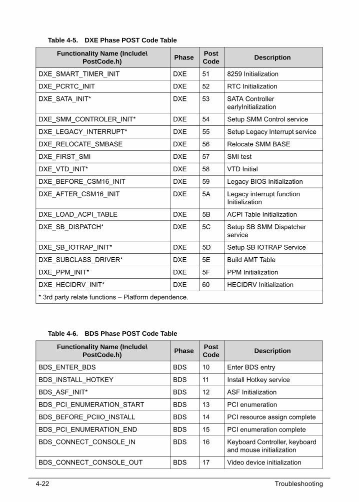
4-22 Troubleshooting
DXE_SMART_TIMER_INIT DXE 51 8259 Initialization
DXE_PCRTC_INIT DXE 52 RTC Initialization
DXE_SATA_INIT* DXE 53 SATA Controller earlyInitialization
DXE_SMM_CONTROLER_INIT* DXE 54 Setup SMM Control service
DXE_LEGACY_INTERRUPT* DXE 55 Setup Legacy Interrupt service
DXE_RELOCATE_SMBASE DXE 56 Relocate SMM BASE
DXE_FIRST_SMI DXE 57 SMI test
DXE_VTD_INIT* DXE 58 VTD Initial
DXE_BEFORE_CSM16_INIT DXE 59 Legacy BIOS Initialization
DXE_AFTER_CSM16_INIT DXE 5A Legacy interrupt function Initialization
DXE_LOAD_ACPI_TABLE DXE 5B ACPI Table Initialization
DXE_SB_DISPATCH* DXE 5C Setup SB SMM Dispatcher service
DXE_SB_IOTRAP_INIT* DXE 5D Setup SB IOTRAP Service
DXE_SUBCLASS_DRIVER* DXE 5E Build AMT Table
DXE_PPM_INIT* DXE 5F PPM Initialization
DXE_HECIDRV_INIT* DXE 60 HECIDRV Initialization
* 3rd party relate functions – Platform dependence.
Table 4-6. BDS Phase POST Code Table
Functionality Name (Include\ PostCode.h)
PhasePost Code
Description
BDS_ENTER_BDS BDS 10 Enter BDS entry
BDS_INSTALL_HOTKEY BDS 11 Install Hotkey service
BDS_ASF_INIT* BDS 12 ASF Initialization
BDS_PCI_ENUMERATION_START BDS 13 PCI enumeration
BDS_BEFORE_PCIIO_INSTALL BDS 14 PCI resource assign complete
BDS_PCI_ENUMERATION_END BDS 15 PCI enumeration complete
BDS_CONNECT_CONSOLE_IN BDS 16 Keyboard Controller, keyboard and mouse initialization
BDS_CONNECT_CONSOLE_OUT BDS 17 Video device initialization
Table 4-5. DXE Phase POST Code Table
Functionality Name (Include\ PostCode.h)
PhasePost Code
Description

Troubleshooting 4-23
BDS_CONNECT_STD_ERR BDS 18 Error report device initialization
BDS_CONNECT_USB_HC BDS 19 USB host controller initialization
BDS_CONNECT_USB_BUS BDS 1A USB BUS driver initialization
BDS_CONNECT_USB_DEVICE BDS 1B USB device driver initialization
BDS_NO_CONSOLE_ACTION BDS 1C Console device initial fail
BDS_DISPLAY_LOGO_SYSTEM_INFO BDS 1D Display logo or system information
BDS_START_IDE_CONTROLLER BDS 1E IDE controller initialization
BDS_START_SATA_CONTROLLER BDS 1F SATA controller initialization
BDS_START_ISA_ACPI_CONTROLLER BDS 20 SIO controller initialization
BDS_START_ISA_BUS BDS 21 ISA BUS driver initialization
BDS_START_ISA_FDD BDS 22 Floppy device initialization
BDS_START_ISA_SEIRAL BDS 23 Serial device initialization
BDS_START_IDE_BUS BDS 24 IDE device initialization
BDS_START_AHCI_BUS BDS 25 AHCI device initialization
BDS_CONNECT_LEGACY_ROM BDS 26 Dispatch option ROMs
BDS_ENUMERATE_ALL_BOOT_OPTION BDS 27 Get boot device information
BDS_END_OF_BOOT_SELECTION BDS 28 End of boot selection
BDS_ENTER_SETUP BDS 29 Enter Setup Menu
BDS_ENTER_BOOT_MANAGER BDS 2A Enter Boot manager
BDS_BOOT_DEVICE_SELECT BDS 2B Try to boot system to OS
BDS_EFI64_SHADOW_ALL_LEGACY_ROM
BDS 2C Shadow Misc Option ROM
BDS_ACPI_S3SAVE BDS 2D Save S3 resume required data in RAM
BDS_READY_TO_BOOT_EVENT BDS 2E Last Chipset initial before boot to OS
BDS_GO_LEGACY_BOOT BDS 2F Start to boot Legacy OS
BDS_GO_UEFI_BOOT BDS 30 Start to boot UEFI OS
BDS_LEGACY16_PREPARE_TO_BOOT BDS 31 Prepare to Boot to Legacy OS
BDS_EXIT_BOOT_SERVICES* BDS 32 Send END of POST Message to ME via HECI
Table 4-6. BDS Phase POST Code Table
Functionality Name (Include\ PostCode.h)
PhasePost Code
Description
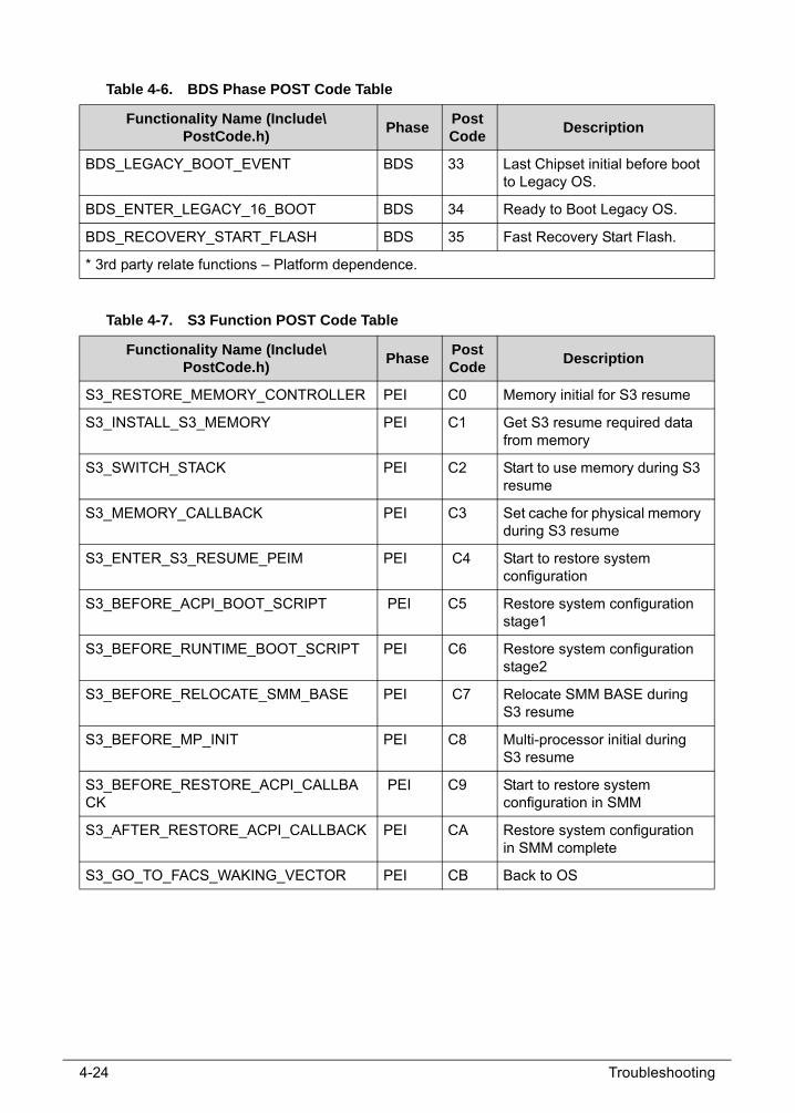
4-24 Troubleshooting
BDS_LEGACY_BOOT_EVENT BDS 33 Last Chipset initial before boot to Legacy OS.
BDS_ENTER_LEGACY_16_BOOT BDS 34 Ready to Boot Legacy OS.
BDS_RECOVERY_START_FLASH BDS 35 Fast Recovery Start Flash.
* 3rd party relate functions – Platform dependence.
Table 4-7. S3 Function POST Code Table
Functionality Name (Include\ PostCode.h)
PhasePost Code
Description
S3_RESTORE_MEMORY_CONTROLLER PEI C0 Memory initial for S3 resume
S3_INSTALL_S3_MEMORY PEI C1 Get S3 resume required data from memory
S3_SWITCH_STACK PEI C2 Start to use memory during S3 resume
S3_MEMORY_CALLBACK PEI C3 Set cache for physical memory during S3 resume
S3_ENTER_S3_RESUME_PEIM PEI C4 Start to restore system configuration
S3_BEFORE_ACPI_BOOT_SCRIPT PEI C5 Restore system configuration stage1
S3_BEFORE_RUNTIME_BOOT_SCRIPT PEI C6 Restore system configuration stage2
S3_BEFORE_RELOCATE_SMM_BASE PEI C7 Relocate SMM BASE during S3 resume
S3_BEFORE_MP_INIT PEI C8 Multi-processor initial during S3 resume
S3_BEFORE_RESTORE_ACPI_CALLBACK
PEI C9 Start to restore system configuration in SMM
S3_AFTER_RESTORE_ACPI_CALLBACK PEI CA Restore system configuration in SMM complete
S3_GO_TO_FACS_WAKING_VECTOR PEI CB Back to OS
Table 4-6. BDS Phase POST Code Table
Functionality Name (Include\ PostCode.h)
PhasePost Code
Description

Troubleshooting 4-25
Table 4-8. ACPI Function POST Table
Functionality Name (Include\ PostCode.h)
PhasePost Code
Description
ASL_ENTER_S1 ASL 51 Prepare to enter S1
ASL_ENTER_S3 ASL 53 Prepare to enter S3
ASL_ENTER_S4 ASL 54 Prepare to enter S4
ASL_ENTER_S5 ASL 55 Prepare to enter S5
ASL_WAKEUP_S1 ASL E1 System wakeup from S1
ASL_WAKEUP_S3 ASL E3 System wakeup from S3
ASL_WAKEUP_S4 ASL E4 System wakeup from S4
Table 4-9. SMM Functions POST Code Table
Functionality Name (Include\ PostCode.h)
PhasePost Code
Description
SMM_IDENTIFY_FLASH_DEVICE SMM 0xA0 Identify Flash device in SMM
SMM_SMM_PLATFORM_INIT SMM 0xA2 SMM service initial
SMM_ACPI_ENABLE_START SMM 0xA6 OS call ACPI enable function
SMM_ACPI_ENABLE_END SMM 0xA7 ACPI enable function complete
SMM_S1_SLEEP_CALLBACK SMM 0xA1 Enter S1
SMM_S3_SLEEP_CALLBACK SMM 0xA3 Enter S3
SMM_S4_SLEEP_CALLBACK SMM 0xA4 Enter S4
SMM_S5_SLEEP_CALLBACK SMM 0xA5 Enter S5
SMM_ACPI_DISABLE_START SMM 0xA8 OS call ACPI disable function
SMM_ACPI_DISABLE_END SMM 0xA9 ACPI disable function complete
Table 4-10. InsydeH2ODDT Debugger POST Code Table
Functionality Name (Include\ PostCode.h)
Post Code Description
Used by Insyde debugger 0x0D Waiting for device connect
Used by Insyde debugger 0xD0 Waiting for device connect
Used by Insyde debugger 0xD1 InsydeH2ODDT Ready
Used by Insyde debugger 0xD2 EHCI not found

4-26 Troubleshooting
Used by Insyde debugger 0xD3 Debug port connect low speed device
Used by Insyde debugger 0xD4 DDT Cable become low speed device
Used by Insyde debugger 0xD5 DDT Cable Transmission Error (Get descriptor fail)
Used by Insyde debugger 0xD6 DDT Cable Transmission Error (Set Debug mode fail)
Used by Insyde debugger 0xD7 DDT Cable Transmission Error (Set address fail)
Table 4-10. InsydeH2ODDT Debugger POST Code Table (Continued)
Functionality Name (Include\ PostCode.h)
Post Code Description

CHAPTER 5Jumper and Connector Locations

5-2
Clearing Password Check and BIOS Recovery . . . . . . . . . . . . . . 5-5Clearing Password Check . . . . . . . . . . . . . . . . . . . . . . . . . . . . .5-5Clear CMOS Jumper . . . . . . . . . . . . . . . . . . . . . . . . . . . . . . . . .5-6BIOS Recovery by Crisis Disk. . . . . . . . . . . . . . . . . . . . . . . . . . .5-7

Jumper and Connector Locations 5-3
Jumper and Connector Locations
Figure 5-1. Mainboard Top
Figure 5-2. Mainboard Bottom
Table 5-1. Mainboard Top
Item Connector Description
1 CON4200 Type-C CON.
Table 5-2. Mainboard Bottom
Item Connector Description
1 SW6003 Battert reset button
2 CON4801 HDMI CON.
3 J5201 USB3.0 CON.
4 CON3701 SPK CON.

5-4 Jumper and Connector Locations
5 J2401 RTC CON.
6 CON5001&CON5002 FAN CON.
7 CON6002 BAT CON.
8 CON6001 DC-IN CON.
9 J3104 KB BL CON.
10 CON3102 Click pad CON.
11 CON3103/CON3105 FP CON.
12 CON3101 KB CON.
13 CON6401 MB to IO CON.
14 CON4501 eDP CON.
15 J5101 SSD CON.
16 CON5301 Wifi CON
Table 5-2. Mainboard Bottom
Item Connector Description
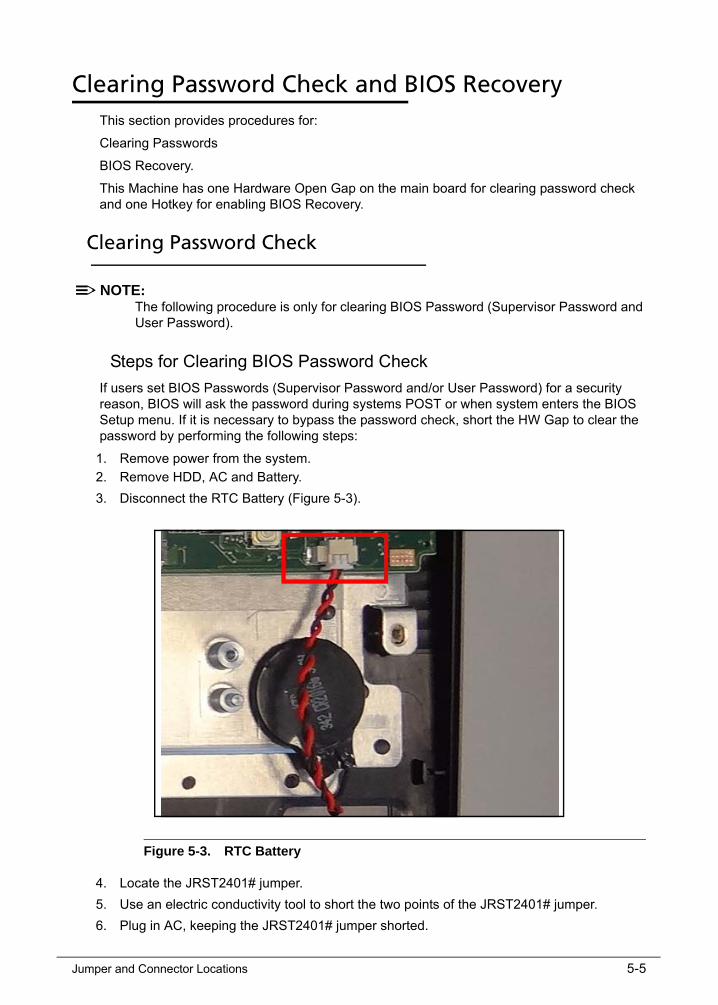
Jumper and Connector Locations 5-5
Clearing Password Check and BIOS Recovery 0
This section provides procedures for:
Clearing Passwords
BIOS Recovery.
This Machine has one Hardware Open Gap on the main board for clearing password check and one Hotkey for enabling BIOS Recovery.
Clearing Password Check 0
NOTE:NOTE:The following procedure is only for clearing BIOS Password (Supervisor Password and User Password).
Steps for Clearing BIOS Password Check 0
If users set BIOS Passwords (Supervisor Password and/or User Password) for a security reason, BIOS will ask the password during systems POST or when system enters the BIOS Setup menu. If it is necessary to bypass the password check, short the HW Gap to clear the password by performing the following steps:
1. Remove power from the system.
2. Remove HDD, AC and Battery.
3. Disconnect the RTC Battery (Figure 5-3).
Figure 5-3. RTC Battery
4. Locate the JRST2401# jumper.
5. Use an electric conductivity tool to short the two points of the JRST2401# jumper.
6. Plug in AC, keeping the JRST2401# jumper shorted.

5-6 Jumper and Connector Locations
7. Press Power Button until BIOS POST is finished, then remove the conductivity tool from the JRST2401# jumper.
8. Restart the system. Press F2 to enter BIOS Setup menu.
9. If there is no Password request, BIOS Password is cleared.
10. If a password is requested, repeat Steps 1 through 9.
Clear CMOS Jumper 0
Figure 5-4. CMOS Jumper
Table 5-3. CMOS Jumper
Item Description
JRST2401 CMOS Jumper

Jumper and Connector Locations 5-7
BIOS Recovery by Crisis Disk 0
BIOS Recovery Boot Block 0
BIOS Recovery Boot Block is a special block of BIOS, used to boot the system with minimum BIOS initialization. Users can enable this feature to restore the BIOS firmware once the previous BIOS flashing process failed.
BIOS Recovery Hotkey 0
A function hotkey- <Fn+Esc>, used to enable the BIOS Recovery process when system is powered On during BIOS POST. To use this function, it is strongly recommended to have the AC adapter and Battery present. If this function is enabled, the system will force the BIOS to enter a special BIOS block, called Boot Block.
Steps for BIOS Recovery from USB Storage 0
NOTE:NOTE:Prior to performing the recovery, prepare a Crisis USB key. The Crisis USB key is created by executing the Crisis Disk program in another system with Windows 10 OS.
To Create a Crisis USB key, perform the following:
1. Copy BIOS file to USB flash disk and rename it to CA4DBX64.fd (flash disk must format to FAT32 format).
2. Power off the system. Plug-in the USB flash disk, and insert AC adapter.
3. Holding down <Fn+Esc> key, and power on the system from off state
4. After system power on, release Fn + ESC key, the system will start recovering the BIOS automatically, and system will shutdown after recovering. (Notice: System will be No display when recovering, it’s normal.)
5. When CRISIS is complete, the system auto restarts with a workable BIOS.
6. Update the latest version BIOS for this machine by regular BIOS flashing process.

5-8 Jumper and Connector Locations

CHAPTER 6FRU List

6-2
Exploded Diagrams . . . . . . . . . . . . . . . . . . . . . . . . . . . . . . . . . . . 6-4Main Assembly . . . . . . . . . . . . . . . . . . . . . . . . . . . . . . . . . . . . .6-4
FRU List . . . . . . . . . . . . . . . . . . . . . . . . . . . . . . . . . . . . . . . . . . . . . 6-6Screw List . . . . . . . . . . . . . . . . . . . . . . . . . . . . . . . . . . . . . . . . . . . 6-16

FRU (Field Replaceable Unit) List 6-3
FRU (Field Replaceable Unit) List
This chapter provides users with a FRU (Field Replaceable Unit) listing in global configurations for the Swift SF314-51 Refer to this chapter whenever ordering for parts to repair or for RMA (Return Merchandise Authorization).
NOTE:NOTE:WHEN ORDERING FRU PARTS, check the most up-to-date information available on the regional web or channel. Part number changes will not be noted on the printed Service Guide. For ACER AUTHORIZED SERVICE PROVIDERS, the Acer office may have a DIFFERENT part number code from those given in the FRU list of this printed Service Guide. Users MUST use the local FRU list provided by the regional Acer office to order FRU parts for repair and service of customer machines.
NOTE:NOTE:To scrap or to return the defective parts, users should follow the local government ordinance or regulations on how to dispose it properly, or follow the rules set by the regional Acer office on how to return it.

6-4 FRU (Field Replaceable Unit) List
Exploded Diagrams 0
Main Assembly 0
Figure 6-1. Main Assembly Exploded Diagram
Table 6-1. Main Assembly Exploded Diagram
Item Description Item Description
1 M34DA(PB) 1A LCD COVER ASSY 16 CA4DB(00) IO TOP SHIELDING
2 LCD TFT 14.0’ FHD LED 17 CA4DB(00) MB T SHIELDING ASSY
3 M34DA(00) 1A LCD BEZEL ASSY 18 CA4DB(00) FP SUP BKT
4 M34DA(PB) 1A TOP CASE ASSY 19 CA4DB(00) MB B SHIELDING ASSY
5 CA4DB MAIN_BD._MODULE/AR 20 CA4DB(00) 1A HINGE CAP ASSY

FRU (Field Replaceable Unit) List 6-5
6 P5HCJ PAN 3220 4S1P 21 SPEAKER MODULE CA4DB(00)
7 AR KB UK CA4DB 297MM(A1) 22 SPEAKER MODULE CA4DB(00)
8 CA4DB(00) CLICKPAD BRKT ASSY 23 CA4DB(00) HINGE L
9 CLICKPAD CA4DB 105*76.7mm 24 SUB BD FFC 34P 0.5mm CA4DB
10 CLICK PAD FFC 8P 1.0 mm CA4DB 25 CA4DB(00) HINGE R
11 M34DA(PB)-1A BOTTOM CASE ASSY
26 FP FFC 6P 0.5mm CA4DB
12 FINGER PRINTER SENSOR 27 CA4DB(00) FP SUP BKT
13 CA4DB(00) UMA THM MOD ASSY 28 SSD M.2 128GB FW:30000P10
14 CA4DB 10L IO 29 CMOS CAMERA 1M HD
15 DC IN CABLE CA4DB 30 WLAN+BT M2 AC 2X2 7265 M2
Table 6-1. (Continued)Main Assembly Exploded Diagram
Item Description Item Description

6-6 FRU (Field Replaceable Unit) List
FRU List 0
Table 6-2. FRU List
Category Acer Description Acer Part No
ADAPTER
Adapter LITE-ON 45W 19V 1.1x3.0x7.5 PA-1450-26AC LF black with acer logo
KP.04503.004
Adapter Chicony Power 45W 19V 1.1x3.0x7.5 A045R016L LF Black with acer logo
KP.0450H.001
Adapter DELTA 45W 19V 1.1x3.0x7.5 ADP-45HE BB LF Black with acer logo
KP.04501.003
BATTERY
Battery SANYO AC14B (5.5mm) Prismatic 4S1P SANYO 4 cell 3220mAh Main COMMON (JPN cell, lower capacity)
KT.00403.032
Battery SANYO AC14B Prismatic 4S1P SANYO 4 cell 3220mAh Main COMMON (KT.00403.032 add BIS logo)
KT.00403.040
Battery LGC AC14B (5.5mm) Prismatic 4S1P LGC 4 cell 3220mAh Main COMMON (KT.0040G.004 add Acer logo)
KT.0040G.006
BOARD
Foxconn 3rd WiFi 2x2 AC+ BT M.2 QCA NFA344A MU-MIMO
NC.23611.030
Liteon 3rd WiFi 2x2 AC+ BT M.2 QCA NFA344A MU-MIMO
NC.23611.02Z
CA4DB IO_BD.//PEGATRON 55.VDFN5.001
CABLE
EDP CABLE CA4DB(00)//HIGH-TEK/0CTPG016007N
50.VDFN5.001
EDP CABLE CA4DB(00)//HONGLIN/250-31201 50.VDFN5.001

FRU (Field Replaceable Unit) List 6-7
FP FFC 6P 0.5mm 329.5mm CA4DB//JINLONG/JA2061H167016
50.VDFN5.002
FP FFC 6P 0.5mm CA4DB//CVILUX/FFCE06091D16Q0090-NH
50.VDFN5.002
CLICK PAD FFC 8P 1.0mm CA4DB//JINLONG/JA3081H167015
50.VDFN5.003
CLICK PAD FFC 8P 1.0mm CA4DB//CVILUX/FFCC08141C16Q0094-NH
50.VDFN5.003
SUB FFC 34P 0.5mm CA4DB//JINLONG/JA2341H167040
50.VDFN5.004
SUB BD FFC 34P 0.5mm CA4DB//CVILUX/FFCE34091B16Q0169-NH
50.VDFN5.004
DC IN CABLE CA4DB//SIMULA/CB2A5B-3200-1YF
50.VDFN5.005
DC IN CABLE CA4DB//MEC/70-5919-300HF 50.VDFN5.005
WLAN ANTENNA MAIN+AUX CA4DB//WNC/81EAAL15.GET
50.VDFN5.006
CASE/COVER/BRACKET ASSEMBLY
M34DA(00) 1A LCD BEZEL ASSY//CQHARDWARE
60.GKKN5.001
M34DA(00) 1B LCD BEZEL ASSY//CQHARDWARE
60.GKBN5.001
M34DA(PB) 1A LCD COVER ASSY//AOJIE 60.GKKN5.002
M34DA(PB) 1B LCD COVER ASSY//AOJIE 60.GKBN5.002
Table 6-2. FRU List (Continued)
Category Acer Description Acer Part No
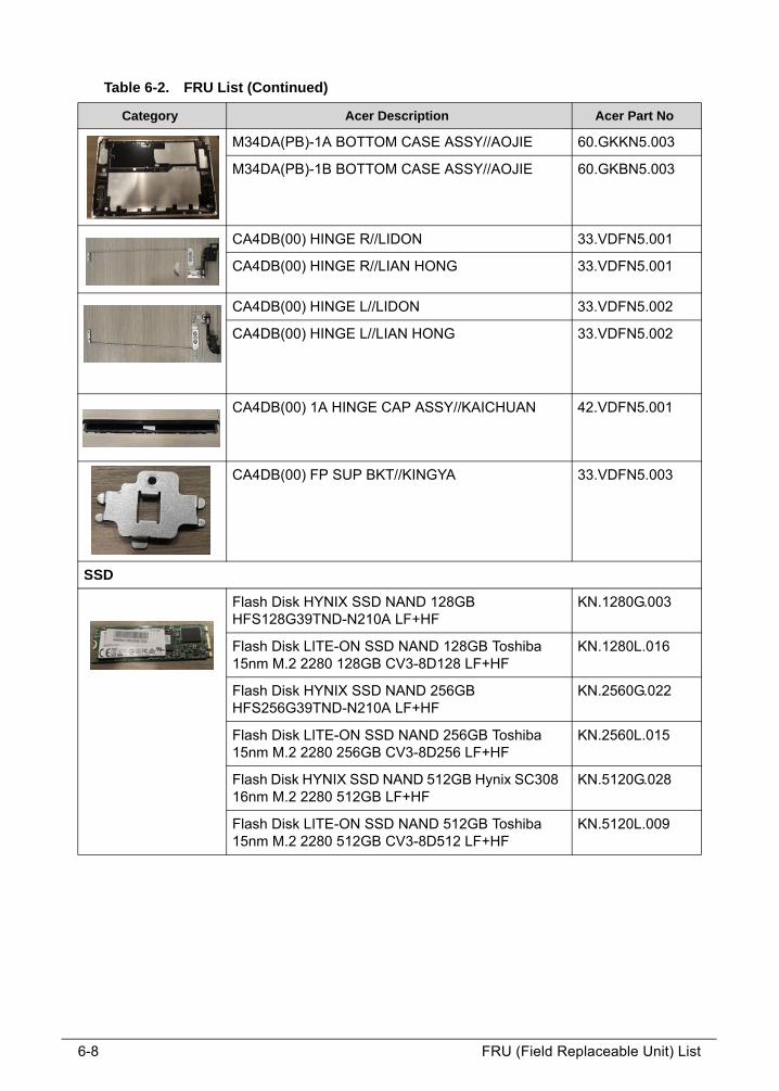
6-8 FRU (Field Replaceable Unit) List
M34DA(PB)-1A BOTTOM CASE ASSY//AOJIE 60.GKKN5.003
M34DA(PB)-1B BOTTOM CASE ASSY//AOJIE 60.GKBN5.003
CA4DB(00) HINGE R//LIDON 33.VDFN5.001
CA4DB(00) HINGE R//LIAN HONG 33.VDFN5.001
CA4DB(00) HINGE L//LIDON 33.VDFN5.002
CA4DB(00) HINGE L//LIAN HONG 33.VDFN5.002
CA4DB(00) 1A HINGE CAP ASSY//KAICHUAN 42.VDFN5.001
CA4DB(00) FP SUP BKT//KINGYA 33.VDFN5.003
SSD
Flash Disk HYNIX SSD NAND 128GB HFS128G39TND-N210A LF+HF
KN.1280G.003
Flash Disk LITE-ON SSD NAND 128GB Toshiba 15nm M.2 2280 128GB CV3-8D128 LF+HF
KN.1280L.016
Flash Disk HYNIX SSD NAND 256GB HFS256G39TND-N210A LF+HF
KN.2560G.022
Flash Disk LITE-ON SSD NAND 256GB Toshiba 15nm M.2 2280 256GB CV3-8D256 LF+HF
KN.2560L.015
Flash Disk HYNIX SSD NAND 512GB Hynix SC308 16nm M.2 2280 512GB LF+HF
KN.5120G.028
Flash Disk LITE-ON SSD NAND 512GB Toshiba 15nm M.2 2280 512GB CV3-8D512 LF+HF
KN.5120L.009
Table 6-2. FRU List (Continued)
Category Acer Description Acer Part No

FRU (Field Replaceable Unit) List 6-9
KB ASSEMBLY
M34DA-1A K/B_(UI)_MODULE W/TOPCASE/BRACKET//PEGATRON
6B.GKKN5.001
M34DA-1A K/B_(FR)_MODULE W/TOPCASE/BRACKET//PEGATRON
6B.GKKN5.002
M34DA-1A K/B_(AR)_MODULE W/TOPCASE/BRACKET//PEGATRON
6B.GKKN5.003
M34DA-1A K/B_(CF)_MODULE W/TOPCASE/BRACKET//PEGATRON
6B.GKKN5.004
M34DA-1A K/B_(WB)_MODULE W/TOPCASE/BRACKET//PEGATRON
6B.GKKN5.005
M34DA-1A K/B_(ND)_MODULE W/TOPCASE/BRACKET//PEGATRON
6B.GKKN5.006
M34DA-1A K/B_(LA)_MODULE W/TOPCASE/BRACKET//PEGATRON
6B.GKKN5.007
M34DA-1A K/B_(GR)_MODULE W/TOPCASE/BRACKET//PEGATRON
6B.GKKN5.008
M34DA-1A K/B_(SP)_MODULE W/TOPCASE/BRACKET//PEGATRON
6B.GKKN5.009
M34DA-1A K/B_(A1)_MODULE W/TOPCASE/BRACKET//PEGATRON
6B.GKKN5.010
M34DA-1A K/B_(KO)_MODULE W/TOPCASE/BRACKET//PEGATRON
6B.GKKN5.011
M34DA-1A K/B_(JP)_MODULE W/TOPCASE/BRACKET//PEGATRON
6B.GKKN5.012
M34DA-1A K/B_(BR)_MODULE W/TOPCASE/BRACKET//PEGATRON
6B.GKKN5.013
M34DA-1A K/B_(E2)_MODULE W/TOPCASE/BRACKET//PEGATRON
6B.GKKN5.014
M34DA-1A K/B_(RU)_MODULE W/TOPCASE/BRACKET//PEGATRON
6B.GKKN5.015
M34DA-1A K/B_(BG)_MODULE W/TOPCASE/BRACKET//PEGATRON
6B.GKKN5.016
M34DA-1A K/B_(GE)_MODULE W/TOPCASE/BRACKET//PEGATRON
6B.GKKN5.017
M34DA-1A K/B_(NW)_MODULE W/TOPCASE/BRACKET//PEGATRON
6B.GKKN5.018
M34DA-1A K/B_(TW)_MODULE W/TOPCASE/BRACKET//PEGATRON
6B.GKKN5.019
Table 6-2. FRU List (Continued)
Category Acer Description Acer Part No

6-10 FRU (Field Replaceable Unit) List
M34DA-1A K/B_(TU)_MODULE W/TOPCASE/BRACKET//PEGATRON
6B.GKKN5.020
M34DA-1A K/B_(SD)_MODULE W/TOPCASE/BRACKET//PEGATRON
6B.GKKN5.021
M34DA-1A K/B_(DE)_MODULE W/TOPCASE/BRACKET//PEGATRON
6B.GKKN5.022
M34DA-1A K/B_(HU)_MODULE W/TOPCASE/BRACKET//PEGATRON
6B.GKKN5.023
M34DA-1A K/B_(SF)_MODULE W/TOPCASE/BRACKET//PEGATRON
6B.GKKN5.024
M34DA-1A K/B_(UK)_MODULE W/TOPCASE/BRACKET//PEGATRON
6B.GKKN5.025
M34DA-1A K/B_(BE)_MODULE W/TOPCASE/BRACKET//PEGATRON
6B.GKKN5.026
M34DA-1A K/B_(IT)_MODULE W/TOPCASE/BRACKET//PEGATRON
6B.GKKN5.027
M34DA-1A K/B_(PO)_MODULE W/TOPCASE/BRACKET//PEGATRON
6B.GKKN5.028
M34DA-1A K/B_(HE)_MODULE W/TOPCASE/BRACKET//PEGATRON
6B.GKKN5.029
M34DA-1A K/B_(TA)_MODULE W/TOPCASE/BRACKET//PEGATRON
6B.GKKN5.030
M34DA-1B K/B_(UI)_MODULE W/TOPCASE/BRACKET//PEGATRON
6B.GKBN5.001
M34DA-1B K/B_(FR)_MODULE W/TOPCASE/BRACKET//PEGATRON
6B.GKBN5.002
M34DA-1B K/B_(AR)_MODULE W/TOPCASE/BRACKET//PEGATRON
6B.GKBN5.003
M34DA-1B K/B_(CF)_MODULE W/TOPCASE/BRACKET//PEGATRON
6B.GKBN5.004
M34DA-1B K/B_(WB)_MODULE W/TOPCASE/BRACKET//PEGATRON
6B.GKBN5.005
M34DA-1B K/B_(ND)_MODULE W/TOPCASE/BRACKET//PEGATRON
6B.GKBN5.006
M34DA-1B K/B_(LA)_MODULE W/TOPCASE/BRACKET//PEGATRON
6B.GKBN5.007
M34DA-1B K/B_(GR)_MODULE W/TOPCASE/BRACKET//PEGATRON
6B.GKBN5.008
M34DA-1B K/B_(SP)_MODULE W/TOPCASE/BRACKET//PEGATRON
6B.GKBN5.009
Table 6-2. FRU List (Continued)
Category Acer Description Acer Part No

FRU (Field Replaceable Unit) List 6-11
M34DA-1B K/B_(A1)_MODULE W/TOPCASE/BRACKET//PEGATRON
6B.GKBN5.010
M34DA-1B K/B_(KO)_MODULE W/TOPCASE/BRACKET//PEGATRON
6B.GKBN5.011
M34DA-1B K/B_(JP)_MODULE W/TOPCASE/BRACKET//PEGATRON
6B.GKBN5.012
M34DA-1B K/B_(BR)_MODULE W/TOPCASE/BRACKET//PEGATRON
6B.GKBN5.013
M34DA-1B K/B_(E2)_MODULE W/TOPCASE/BRACKET//PEGATRON
6B.GKBN5.014
M34DA-1B K/B_(RU)_MODULE W/TOPCASE/BRACKET//PEGATRON
6B.GKBN5.015
M34DA-1B K/B_(BG)_MODULE W/TOPCASE/BRACKET//PEGATRON
6B.GKBN5.016
M34DA-1B K/B_(GE)_MODULE W/TOPCASE/BRACKET//PEGATRON
6B.GKBN5.017
M34DA-1B K/B_(NW)_MODULE W/TOPCASE/BRACKET//PEGATRON
6B.GKBN5.018
M34DA-1B K/B_(TW)_MODULE W/TOPCASE/BRACKET//PEGATRON
6B.GKBN5.019
M34DA-1B K/B_(TU)_MODULE W/TOPCASE/BRACKET//PEGATRON
6B.GKBN5.020
M34DA-1B K/B_(SD)_MODULE W/TOPCASE/BRACKET//PEGATRON
6B.GKBN5.021
M34DA-1B K/B_(DE)_MODULE W/TOPCASE/BRACKET//PEGATRON
6B.GKBN5.022
M34DA-1B K/B_(HU)_MODULE W/TOPCASE/BRACKET//PEGATRON
6B.GKBN5.023
M34DA-1B K/B_(SF)_MODULE W/TOPCASE/BRACKET//PEGATRON
6B.GKBN5.024
M34DA-1B K/B_(UK)_MODULE W/TOPCASE/BRACKET//PEGATRON
6B.GKBN5.025
M34DA-1B K/B_(BE)_MODULE W/TOPCASE/BRACKET//PEGATRON
6B.GKBN5.026
M34DA-1B K/B_(IT)_MODULE W/TOPCASE/BRACKET//PEGATRON
6B.GKBN5.027
M34DA-1B K/B_(PO)_MODULE W/TOPCASE/BRACKET//PEGATRON
6B.GKBN5.028
M34DA-1B K/B_(HE)_MODULE W/TOPCASE/BRACKET//PEGATRON
6B.GKBN5.029
Table 6-2. FRU List (Continued)
Category Acer Description Acer Part No

6-12 FRU (Field Replaceable Unit) List
M34DA-1B K/B_(TA)_MODULE W/TOPCASE/BRACKET//PEGATRON
6B.GKBN5.030
LCD
LED LCD Panel AUO 14' FHD None Glare B140HAN02.1 LF 220nit 25ms 700:1 (eDP1.2) (Value IPS) (3.0mm)
KL.14005.029
LED LCD Panel CMI 14' FHD None Glare N140HCA-EAB LF 250nit 25ms 700:1 FHD value IPS
KL.1400D.021
LED LCD Panel AUO 14' WXGA None Glare B140XTN02.E LF 220nit 8ms 400:1 (eDP) new panel for 2015
KL.14005.020
LED LCD Panel CMI 14' WXGA None Glare N140BGA-EA3 LF 220nit 10ms 500:1 (eDP, 3.0mm Max)
KL.1400D.020
LED LCD Panel AUO 14' WXGA Glare B140XTK01.0 LF 200nit 8ms 500:1 (eDP) total solution oTP lite
KL.14005.023
FINGER PRINT
LTT ETU801 module NC.22011.002
MAINBOARD
CA4DB MB/944338 I5-6200U 2.3G SR2EY/4G //PEGATRON
NB.VDF11.003
CA4DB MB/944338 I5-6200U 2.3G SR2EY/8G//PEGATRON
NB.VDF11.004
CA4DB MB/944334 I3-6100U 2.3G SR2EU/4G//PEGATRON
NB.VDF11.001
CA4DB MB/944334 I3-6100U 2.3G SR2EU/8G//PEGATRON
NB.VDF11.002
CA4DB MB/944339 I7-6500U 2.5G SR2EZ/4G//PEGATRON
NB.VDF11.005
CA4DB MB/944339 I7-6500U 2.5G SR2EZ/8G//PEGATRON
NB.VDF11.006
Table 6-2. FRU List (Continued)
Category Acer Description Acer Part No

FRU (Field Replaceable Unit) List 6-13
THEMERAL MODULE
CA4DB(00) UMA THM MOD ASSY//FORCECON 60.VDFN5.004
SPEAKER
SPEAKER MODULE CA4DB(00)//FORGRAND/FG-PGT043000
23.VDFN5.001
SPEAKER MODULE CA4DB(00)//SNC/SNCN-0000027
23.VDFN5.001
CAMERA
Camera CHICONY HD Camera CH_OV9728_SPA2087 AOET Unified 2
KS.0HD06.001
Camera LITEON HD Camera LT_HM1061_RTS5838H AOET Unified 2
KS.0HD05.004
MISCELLANEOUS
P4GCR(00) HINGE GASKET//E-POWER 47.VDFN5.001
P3HCJ SSD AL MYLAR//EASYRUN 47.G8SN5.001
TOUCHPAD
M34DA-1A CLICKPAD ASSY(ELAN) w/bracket & mylar//PEGATRON
56.GKKN5.001
M34DA-1A CLICKPAD ASSY(Synaptics)w/bracket & mylar//PEGATRON
56.GKKN5.002
M34DA-1B CLICKPAD ASSY(ELAN) w/bracket & mylar//PEGATRON
56.GKBN5.001
M34DA-1B CLICKPAD ASSY(Synaptics)w/bracket & mylar//PEGATRON
56.GKBN5.002
Power cord
POWER CORD 1.0M BLACK 3 PIN JAPAN 27.V5M0U.001
POWER CORD 1.0M BLACK 3 PIN JAPAN 27.V5M0U.001
POWER CORD 1.0M BLACK 3 PIN US 27.RN60U.003
POWER CORD 1.0M BLACK 3 PIN US 27.RN60U.003
Table 6-2. FRU List (Continued)
Category Acer Description Acer Part No

6-14 FRU (Field Replaceable Unit) List
POWER CORD 1.0M BLACK 3 PIN US 27.RN60U.003
POWER CORD 1.0M BLACK 3 PIN UK 27.RN60U.008
POWER CORD 1.0M BLACK 3 PIN UK 27.RN60U.008
POWER CORD 1.0M BLACK 3 PIN UK 27.RN60U.008
POWER CORD 1.0M BLACK 3 PIN EU 27.RN60U.002
POWER CORD 1.0M BLACK 3 PIN EU 27.RN60U.002
POWER CORD 1.0M BLACK 3 PIN DANISH 27.RN60U.001
POWER CORD 1.0M BLACK 3 PIN DANISH 27.RN60U.001
POWER CORD 1.0M BLACK 3 PIN DANISH 27.RN60U.001
POWER CORD 1M BLACK 3 PIN ITALY 27.RN60U.005
POWER CORD 1M BLACK 3 PIN ITALY 27.RN60U.005
POWER CORD 1M BLACK 3 PIN ITALY 27.RN60U.005
POWER CORD 1.0M BLACK 3 PIN AF 27.RN60U.007
POWER CORD 1.0M BLACK 3 PIN AF 27.RN60U.007
POWER CORD 1.0M BLACK 3 PIN AF 27.RN60U.007
POWER CORD 1.0M BLACK 3 PIN US-110V (BSMI)
27.V6ZN5.001
POWER CORD 1.0M BLACK 3 PIN US-110V (BSMI)
27.V6ZN5.001
POWER CORD 1.0M BLACK 3 PIN US-110V (BSMI)
27.V6ZN5.001
POWER CORD 1.0M BLACK 3 PIN AU 27.RN60U.009
POWER CORD 1.0M BLACK 3 PIN AU 27.RN60U.009
POWER CORD 1.0M BLACK 3 PIN AU 27.RN60U.009
POWER CORD 1.0M BLACK 3 PIN INDIA 27.V5M0U.002
POWER CORD 1.0M BLACK 3 PIN INDIA 27.V5M0U.002
POWER CORD 1.0M BLACK 3 PIN SWISS 27.RN60U.004
POWER CORD 1.0M BLACK 3 PIN SWISS 27.RN60U.004
POWER CORD 1.0M BLACK 3 PIN SWISS 27.RN60U.004
POWER CORD 1.0M BLACK 3 PIN ISRAEL 27.GC2N5.003
POWER CORD 1.0M BLACK 3 PIN ISRAEL 27.GC2N5.003
POWER CORD 1.0M BLACK 3 PIN Brazil IMETRO 27.MHMN5.001
POWER CORD 1.0M BLACK 3 PIN Brazil IMETRO 27.MHMN5.001
POWER CORD 1.0M BLACK 3 PIN Brazil IMETRO 27.MHMN5.001
Table 6-2. FRU List (Continued)
Category Acer Description Acer Part No

FRU (Field Replaceable Unit) List 6-15
POWER CORD 1.0M BLACK 3 PIN ARGENTINA 27.GC2N5.004
POWER CORD 1.0M BLACK 3 PIN ARGENTINA 27.GC2N5.004
POWER CORD 1.0M BLACK 3 PIN ARGENTINA 27.GC2N5.004
POWER CORD 1.0M BLACK 3 PIN PRC 27.RN60U.006
POWER CORD 1.0M BLACK 3 PIN PRC 27.RN60U.006
POWER CORD 1.0M BLACK 3 PIN PRC 27.RN60U.006
Table 6-2. FRU List (Continued)
Category Acer Description Acer Part No

6-16 FRU (Field Replaceable Unit) List
Screw List 0
Table 6-3. Screw List
Category Description Acer Part No.
Screw
SCREW M2*2.5L(K,D4.5) B-NI,NY//GERLENG/TERESA 86.VDFN5.001
SCREW M2*4L K B-NI #1 NY//KL D=4.5 86.VDFN5.002
SCREW M2*6.5L K B-NI #1 NY//KL D=4.5 86.VDFN5.003
SCREW M2*2L (K) B-ZN #1 NY//GERLENG D=7.0 86.RYNN5.004
SCREW M2*3L K W-NI #1 NY//KL MACHINE D=4.5 H=0.4 86.Q04N5.009
SCREW M2*4L (K) B-NI,NY//GL;BLUE 86.B430U.006
CHAPTER 7Test Compatible Components

7-2
Microsoft® Windows® 10 Environment Test . . . . . . . . . . . . . . 7-4Swift SF314-51 . . . . . . . . . . . . . . . . . . . . . . . . . . . . . . . . . . . . .7-4

Test Compatible Components 7-3
Test Compatible Components
This computer’s compatibility is tested and verified by Acer’s internal testing department. All
of its system functions are tested under Windows® Windows® 10 environment.
Refer to the following lists for components, adapter cards, and peripherals which have passed these tests. Regarding configuration, combination and test procedures, please refer to the Compatibility Test Report released by the Acer Mobile System Testing Department.

7-4 Test Compatible Components
Microsoft® Windows® 10 Environment Test 0
Swift SF314-51 0
Table 8-1. Swift SF314-51
Vendor Type Description Part No.
Adapter
60035715 DELTA-SINGAPORE
45W_3phy Adapter DELTA 45W 19V 1.1x3.0x7.7 ADP-45HE BB LF Black with acer logo
KP.04501.003
60035715 DELTA-SINGAPORE
45W_3phy Adapter DELTA 45W 19V 1.1x3.0x7.7 ADP-45HE DB LF black with acer logo, cost
KP.04501.012
60036752 LITE-ON SINGAPORE
45W_3phy Adapter LITE-ON 45W 19V 1.1x3.0x7.7 PA-1450-26AC LF black with acer logo
KP.04503.004
60016453 CHICONY POWER
45W_3phy Adapter Chicony Power 45W 19V 1.1x3.0x7.7 A045R016L LF Black with acer logo
KP.0450H.001
Audio Codec
10004786 REALTEK
Non-AVAP Audio Codec - Realtek ALC255(HDA)
Non-AVAP Audio Codec - Realtek ALC255(HDA)
NC.21011.02R
Battery
60001921 SANYO
4CELL3.22 Battery SANYO AC14B Prismatic 4S1P SANYO 4 cell 3220mAh Main COMMON (KT.00403.032 add BIS logo)
KT.00403.040
60032811 LGC
4CELL3.22 Battery LGC AC14B (5.5mm) Prismatic 4S1P LGC 4 cell 3220mAh Main COMMON (KT.0040G.004 add Acer logo)
KT.0040G.006
Camera
10001023 LITE-ON
HD_Unified Camera LITEON HD Camera LT_HM1061_RTS5838H AOET Unified 2
KS.0HD05.004
10001044 CHICONY
HD_Unified Camera CHICONY HD Camera CH_OV9728_SPA2087 AOET Unified 2
KS.0HD06.001

Test Compatible Components 7-5
CPU
10001067 INTEL
Ci36100U CPU(BGA) Intel Core i3 i3-6100U BGA Skylake SR2EU
KC.61001.U00
10001067 INTEL
Ci56200U CPU(BGA) Intel Core i5 i5-6200U BGA Skylake SR2EY
KC.62001.U00
10001067 INTEL
Ci76500U CPU(BGA) Intel Core i7 i7-6500U BGA Skylake SR2EZ
KC.65001.U00
10001067 INTEL
PMD4405U CPU(BGA) Intel PentiumM 4405U BGA Skylake
KC.44001.5UB
HDD
10002146 TOSHIBA
F80128S3 Flash Disk TOSHIBA SSD NAND 128GB SG5 15nm M.2 2280 THNSNK128GVN8 LF+HF
KN.1280A.010
60002045 SK HYNIX
F80128S3 Flash Disk HYNIX SSD NAND 128GB HFS128G39TND-N210A LF+HF
KN.1280G.003
10001023 LITE-ON
F80128S3 Flash Disk LITE-ON SSD NAND 128GB Toshiba 15nm M.2 2280 128GB CV3-8D128 LF+HF
KN.1280L.016
10002146 TOSHIBA
F80256S3 Flash Disk TOSHIBA SSD NAND 256GB SG5 15nm M.2 2280 THNSNK256GVN8 LF+HF
KN.2560A.011
60002045 SK HYNIX
F80256S3 Flash Disk HYNIX SSD NAND 256GB HFS256G39TND-N210A LF+HF
KN.2560G.022
10001023 LITE-ON
F80256S3 Flash Disk LITE-ON SSD NAND 256GB Toshiba 15nm M.2 2280 256GB CV3-8D256 LF+HF
KN.2560L.015
10002146 TOSHIBA
F80512S3 Flash Disk TOSHIBA SSD NAND 512GB SG5 15nm M.2 2280 THNSNK512GVN8 LF+HF
KN.5120A.010
60002045 SK HYNIX
F80512S3 Flash Disk HYNIX SSD NAND 512GB Hynix SC308 16nm M.2 2280 512GB LF+HF
KN.5120G.028
10001023 LITE-ON
F80512S3 Flash Disk LITE-ON SSD NAND 512GB Toshiba 15nm M.2 2280 512GB CV3-8D512 LF+HF
KN.5120L.009
Keyboard
60004864 DARFON
LV4P_A51BWL Phantom KB DARFON LV4P_A51BWL LV4P Internal 14 Standard Black Y2015 Acer Legend Fine Power+Dish White Backlit
NK.I1417.0JX
Table 8-1. Swift SF314-51
Vendor Type Description Part No.

7-6 Test Compatible Components
10001044 CHICONY
LV4T_A51B Phantom KB CHICONY LV4T_A51B LV4T Internal 14 Standard Black Y2015 Acer Legend Win 8 Fine Power+Dish
NK.I1413.0BU
60052236 SUNREX
LV4T_A51B Phantom KB SUNREX LV4T_A51B LV4T Internal 14 Standard Black Y2015 Acer Legend Win 8 Fine Power+Dish
NK.I141S.04K
LAN
10000981 MISC
none LAN LAN none LAN without LAN NI.22400.051
MEM
60002050 MICRON SG
CM4GbIV Memory Chip MICRON DDRIV 2400 4Gb MT40A256M16GE-083E:B LF+HF 256*16
KN.00404.010
60002215 SAMSUNG
CM4GbIV Memory Chip SAMSUNG DDRIV 2133 4Gb K4A4G165WD-BCPB LF+HF 256*16
KN.0040B.010
60002215 SAMSUNG
CM4GbIV Memory Chip SAMSUNG DDRIV 2400 4Gb K4A4G165WE-BCRC LF+HF 256*16 20nm
KN.0040B.014
60002045 SK HYNIX
CM4GbIV Memory Chip HYNIX DDRIV 2133 4Gb H5AN4G6NAFR-TF LF+HF 256*16
KN.0040G.015
60002045 SK HYNIX
CM4GbIV Memory Chip HYNIX DDRIV 2400 4Gb H5AN4G6NAFR-UHC LF+HF 256*16
KN.0040G.016
60002050 MICRON SG
CM8GbIV Memory Chip MICRON DDRIV 2400 8Gb MT40A512M16JY-083E:B LF+HF 512*16 20nm
KN.8GB04.013
60002215 SAMSUNG
CM8GbIV Memory Chip SAMSUNG DDRIV 2133 8Gb K4A8G165WB-BCPB LF+HF 512*16 20nm
KN.8GB0B.036
60002215 SAMSUNG
CM8GbIV Memory Chip SAMSUNG DDRIV 2400 8Gb K4A8G165WB-BCRC LF+HF 512*16 20nm
KN.8GB0B.048
60002045 SK HYNIX
CM8GbIV Memory Chip HYNIX DDRIV 2400 8Gb H5AN8G6NAFR-UHC LF+HF 512*16 21nm
KN.8GB0G.049
60002041 QIMONDA
OB4GBIV(256x16*8)
Memory Chip DDRIV 4GB Dummy LF+HF 256*16
KN.4GB00.017
60002041 QIMONDA
OB8GBIV(512x16*8)
Memory Chip DDRIV 8GB Dummy LF+HF 512*16
KN.8GB00.007
Table 8-1. Swift SF314-51
Vendor Type Description Part No.

Test Compatible Components 7-7
NB Chipset
10000981 MISC
none NB Chipset
NB Chipset none NB Chipset without NB Chipset
KI.22600.054
VGA Chip
10001067 INTEL
UMA UMA (Intel) KI.23200.038
Wireless LAN
10001018 HON HAI
3rd WiFi 2x2 AC+ BT M.2
Foxconn 3rd WiFi 2x2 AC+ BT M.2 QCA NFA344A MU-MIMO
NC.23611.02Z
10001023 LITE-ON
3rd WiFi 2x2 AC+ BT M.2
Liteon 3rd WiFi 2x2 AC+ BT M.2 QCA NFA344A MU-MIMO
NC.23611.030
A cover
10411482 AOJIE(HK)
Luxury Gold 14 Al Anodize SH
AOJIE A cover Luxury Gold 14 Al Anodize SH
NC.21011.09C
10411482 AOJIE(HK)
Sparkly Silver 14 Al Anodize SH
AOJIE A cover Sparkly Silver 14 Al Anodize SH
NC.21011.09S
B cover
10006583 PEGATRON
Luxury Gold 14 Al Texture w/ Camera SH
PEGATRON B cover Luxury Gold 14 Al Texture w/ Camera SH
NC.21011.09D
10006583 PEGATRON
Sparkly Silver 14 Al Texture w/ Camera SH
PEGATRON B cover Sparkly Silver 14 Al Texture w/ Camera SH
NC.21011.09T
C cover
10411482 AOJIE(HK)
Luxury Gold 14 Al Anodize SH
AOJIE C cover Luxury Gold 14 Al Anodize SH
NC.21011.09E
10411482 AOJIE(HK)
Sparkly Silver 14 Al Anodize SH
AOJIE C cover Sparkly Silver 14 Al Anodize SH
NC.21011.09U
D cover
10411482 AOJIE(HK)
Luxury Gold 14 Al Anodize SH
AOJIE D cover Luxury Gold 14 Al Anodize SH
NC.21011.09F
10411482 AOJIE(HK)
Sparkly Silver 14 Al Anodize SH
AOJIE D cover Sparkly Silver 14 Al Anodize SH
NC.21011.09V
Software
10000981 MISC
McAfee Antivirus application McAfee SR.23900.001
Table 8-1. Swift SF314-51
Vendor Type Description Part No.

7-8 Test Compatible Components
WiFi Antenna
Antivirus application McAfee
PIFA 1.4 WNC PIFA 1.4 WiFi Antenna NC.23511.002
LCD
60003316 AUO
N14FHDSUPIL LED LCD Panel AUO 14' FHD None Glare B140HAN02.1 LF 220nit 25ms 700:1 (eDP1.2) (Value IPS) (3.0mm)
KL.14005.029
60031663 CMI STSP BRANCH
N14FHDSUPIL LED LCD Panel CMI 14' FHD None Glare N140HCA-EAB LF 250nit 25ms 700:1 FHD value IPS
KL.1400D.021
60003316 AUO
N14FHDSUPIL LED LCD Panel AUO 14' WXGA Glare B140XTK01.0 LF 200nit 8ms 500:1 (eDP) total solution oTP lite
KL.14005.023
60003316 AUO
N14HDSUP LED LCD Panel AUO 14' WXGA None Glare B140XTN02.E LF 220nit 8ms 400:1 (eDP) new panel for 2015
KL.14005.020
60031663 CMI STSP BRANCH
N14HDSUP LED LCD Panel CMI 14' WXGA None Glare N140BGA-EA3 LF 220nit 10ms 500:1 (eDP, 3.0mm Max)
KL.1400D.020
Packaging
10001071 GOLDEN ARROW
2016-E-Brown 2016 Package WW E series Brown Rev 1.0
NC.25811.04G
10001071 GOLDEN ARROW
2016-S-Brown 11"~15" Brown Box w/o QG & w/o Handle Rev 1.0
NC.25811.085
Touchpad
60040547 SYNAPTICS
CP5WIP1M Synaptics Touchpad CP5WIP1M PTP TM-P3218-003 105x76.7mm PCB (add noise immunity)
NC.24611.039
60040786 ELANTECH
CP5WIP1M Elantec Touchpad CP5WIP1M PTP SA577C-1202 105x76.7mm PCB
NC.24611.02S
Finger Print
PLM00019 LTT
ETU801 module
LTT ETU801 module NC.22011.002
Card Reader
10000981 MISC
Non AVAP SD card reader
Non AVAP SD card reader NC.21511.003
Table 8-1. Swift SF314-51
Vendor Type Description Part No.

CHAPTER 8Online Support Information

8-2
Introduction . . . . . . . . . . . . . . . . . . . . . . . . . . . . . . . . . . . . . . . . . 8-3

Online Support Information 8-3
Online Support Information
Introduction 0
This section describes online technical support services available to help users repair their Acer Systems.
For distributors, dealers, ASP or TPM, please refer the technical queries to a local Acer branch office. Acer Branch Offices and Regional Business Units may access our website. However some information sources will require a user i.d. and password. These can be obtained directly from Acer CSD Taiwan.
Acer's Website offers convenient and valuable support resources.
In the Technical Information section users can download information on all of Acer's Notebook, Desktop and Server models including:
Service guides for all models
Bios updates
Software utilities
Spare parts lists
TABs (Technical Announcement Bulletin)
For these purposes, we have included an Acrobat File to facilitate the problem-free downloading of our technical material.
Also contained on this website are:
Detailed information on Acer's International Traveller’s Warranty (ITW)
Returned material authorization procedures
An overview of all the support services we offer, accompanied by a list of telephone, fax and email contacts for all technical queries.
We are always looking for ways to optimize and improve our services, so do not hesitate to direct any suggestions or comments to us.

8-4 Online Support Information


![Инструкция по эксплуатации Acer Swift SF314-57G · 2019. 12. 25. · 1.оП нажатию ссылки откроется веб-страница [Support]](https://img.dokumen.tips/doc/110x75/6031628aaeeba723d9321cc7/f-f-acer-swift-sf314-57g-2019-12.jpg)