Embed Size (px)
Citation preview

1.0 GENERAL DESCRIPTION
The Swing Wheel Low Loader is a rear-loading heavy equipment low loader,with a unique method of swinging the wheels aside to permit loading on afixed, inbuilt ramp at the rear of the machine. The complete loading processcan be a one man operation taking less than 10 minutes, and with no need forany ramp other than that formed by the structure. The wheel action isparticularly simple, involving merely a rotation of the “swing arms” supportingthe wheels, about a single axis.
This axis is inclined in two planes so as to produce the required motion oflifting the wheels off the ground, yet maintaining the wheels in a near-verticalplane for ease of tyre change out. The swing arms are positively located inplace by a "twist-lock" arrangement driven by hydraulic cylinders.
SW450 SWING WHEEL LOW LOADER
T 07 3839 2349
F 07 3832 3491
www.loadquip.com.au
PO BOX 247, SPRING HILL,
BRISBANE, Q. 4004
2ND FLOOR,
457 EDWARD ST

During this swinging action, the low loader is secured by the park brakes ofthe prime mover and the jacks contacting the ground adjacent to the swingarms. At no time is the rear of the trailer unsecured – either the trailer brakesare fully locked on, or the jacks or underside of the ramp, are loaded againstthe ground. This allows safe unloading of the machine on sloping ground, asthere is no position where the rear of the trailer is not safely secured fromunexpected motion, by either the jacks, or by the rear wheels, which remainlocked by the park brakes throughout the swinging process.
It is possible to complete a load or unload cycle in about 10 minutes, with theswinging of the swing arms taking up the majority of this time. The speed ofthis motion has been deliberately set low to minimise any safety issuesrelating to moving these relatively large masses.
T 07 3839 2349
F 07 3832 3491
www.loadquip.com.au
PO BOX 247, SPRING HILL,
BRISBANE, Q. 4004
2ND FLOOR,
457 EDWARD ST
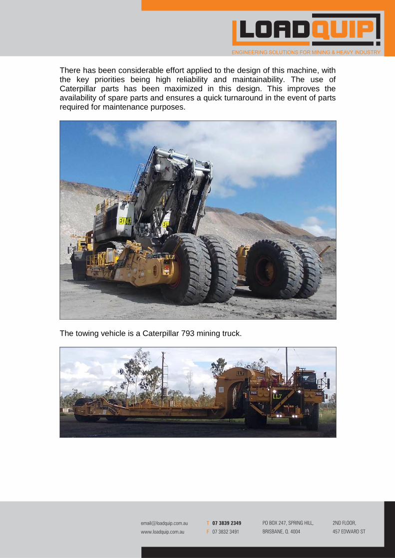
There has been considerable effort applied to the design of this machine, withthe key priorities being high reliability and maintainability. The use ofCaterpillar parts has been maximized in this design. This improves theavailability of spare parts and ensures a quick turnaround in the event of partsrequired for maintenance purposes.
The towing vehicle is a Caterpillar 793 mining truck.
T 07 3839 2349
F 07 3832 3491
www.loadquip.com.au
PO BOX 247, SPRING HILL,
BRISBANE, Q. 4004
2ND FLOOR,
457 EDWARD ST

Table 1.1 sets out a summary of the principal specifications of the low loader.
Model: SW450 Swing Wheel Low Loader
Prime Mover: Caterpillar 793
Capacity: 450 tonne
Top Speed: 39 km/h (assuming 2.5% rolling resistance & gear ratio change)
Top Speed (loaded): 20 km/h (deliberately restricted when loaded)
Tyres: 50/80 R57 (or optional 40R57)
Trailer Hubs: Caterpillar 793D
Working Height: 6.5 m (Unloaded)
Operating Width: 10.4 m (Light Clearance)
Low Loader Width: 10.4 m
Overall Length: 38.6 m
Typical Loading Cycle: 10 minutes
Turning Circle: Radius: 25 m, Diameter: 50 m (SAE J695 Definition)
TABLE 1.1 MACHINE SPECIFICATIONS
T 07 3839 2349
F 07 3832 3491
www.loadquip.com.au
PO BOX 247, SPRING HILL,
BRISBANE, Q. 4004
2ND FLOOR,
457 EDWARD ST

T 07 3839 2349
F 07 3832 3491
www.loadquip.com.au
PO BOX 247, SPRING HILL,
BRISBANE, Q. 4004
2ND FLOOR,
457 EDWARD ST

2.0 MACHINE CAPABILITIES
2.1 Performance
With a 450 tonne payload the low loader has sufficient rimpull to climb typicalgrades on mine sites, but gradability may be improved by installing a gearratio change on the prime mover. Advice on the need for the ratio change canbe provided based on the expected site conditions and payload requirements.
2.2 Braking System
The low loader has Caterpillar 793 hubs at the rear, which include oil-cooledbrakes, which are fully integrated with the prime mover.
It is a very simple and robust braking system, which draws on cooling capacitythat is already available in the prime mover and which would otherwise beunder-utilised because of the lack of a dump body and its contents.
This cooling system design ensures that full oil flow is maintained regardlessof vehicle ground speed, and the cooling system continues to operate at lowspeed and after the vehicle has stopped, allowing brakes heated by anemergency stop or the descent of a ramp to be cooled before resumingoperation.
T 07 3839 2349
F 07 3832 3491
www.loadquip.com.au
PO BOX 247, SPRING HILL,
BRISBANE, Q. 4004
2ND FLOOR,
457 EDWARD ST

With a ground-driven cooling system of some other manufacturer’s lowloaders, additional components would be required to provide the drive, andthis is an additional cost that is not necessary for the configuration thismachine uses, particularly as this approach fails to utilise the already availablecooling in the prime mover.
The prime-mover braking uses air-over-hydraulic actuation, and is unchanged.Trailer brake actuation is electric-over-hydraulic, operating from a pressuresensor in the prime-mover rear-axle brake system. The trailer service brakesare each applied by a Caterpillar pressure-proportional hydraulic solenoid,using pressurised oil from the prime-mover brake-release circuit.
Pressure sensors in the trailer brake circuit provide feedback that the desiredpressure has been achieved. Electric actuation enables the brake balancebetween prime mover and trailer to be varied during setup. This also meansthat there is no need for any air supply on the trailer at all. As brakeactuation relies on sensing oil pressure and then electric actuation, there isnegligible delay with the actuation of the trailer brakes relative to the primemover brakes, thereby limiting the potential for jack-knife.
3.0 MECHANICAL
3.1 Hydraulics and Controls
The low loader uses industry-standard hydraulic components, fittings andhoses in a conservative design for a long period of trouble-free operation.Extensive use is made of filters, relief valves and limit switches to protect thesystem.
A control station is located on a platform at the top of the stairs at the rear ofthe machine. This is a suitable position for the operator to closely observe thejacking and swing arm operation from a safe vantage point. An engineshutdown button is provided, which shuts the prime mover engine down ifrequired. Audible signals alert the operator of normal or abnormal operation.
The control is executed through a standard Caterpillar CMPD (Colour MarinePower Display), which provides a simple means of control, and clear errormessages. A second CMPD is provided in the cab as a display only, but itdoes not offer control capability of the system, as the operator cannot safelysee the critical areas from the cab.
A maintenance mode is available on a separate locked panel, so that suitablyqualified personnel can operate any hydraulic function independently of anyother. This is needed for maintenance tasks relating to any hydraulic function,or for moving the swing arms during tyre changing.
T 07 3839 2349
F 07 3832 3491
www.loadquip.com.au
PO BOX 247, SPRING HILL,
BRISBANE, Q. 4004
2ND FLOOR,
457 EDWARD ST

The control station provides fully automatic control of the jacking and swingingfunctions of the cylinders. Appropriate pressure transducers and proximitysensors are incorporated into the system to ensure failsafe sequencing of thelift and swing cylinders. Appropriate interlocks are also provided on thetransmission and park brake to ensure that the machine cannot be movedwhen it is on the jacks, when the wheels are swung out, or when the stairs arelowered.
Power for the jack and swing wheel cylinders for the low loader comes fromthe hoist pump on the prime mover. Using this as the power source allows therear of the machine to be lifted clear of the ground in approximately oneminute. A complete jack and swing cycle will take under three minutes withthe prime mover engine simply idling. Faster cycle times are possible at high-idle, but this is not seen as a significant advantage. Cycle times are adjustablewithin a range, with the jack and swing rates independently adjustable duringcommissioning.
The jack cylinders incorporate counter balance valves to ensure that the jacksdo not collapse in the event of a hose failure.
Hydraulic cylinders are used to rotate the swing arms in and out, but when inposition, the swing arms are locked in place by twist locks driven in place bysmall hydraulic cylinders. Stresses in all pivot pins in the swing arms areconservatively low, giving added safety to the operation.
T 07 3839 2349
F 07 3832 3491
www.loadquip.com.au
PO BOX 247, SPRING HILL,
BRISBANE, Q. 4004
2ND FLOOR,
457 EDWARD ST

Also, the swing cylinders are fitted with counter balance valves, so that hosefailure would not result in an uncontrolled swinging motion.
Twist Lock Mechanism
3.2 Lubrication
A metering grease lubrication system is installed close to the control station.It is controlled by the Caterpillar ECM (Electronic Control Module), and isresponsible for lubricating the swing arm thrust bearings and lock pins.
T 07 3839 2349
F 07 3832 3491
www.loadquip.com.au
PO BOX 247, SPRING HILL,
BRISBANE, Q. 4004
2ND FLOOR,
457 EDWARD ST

The trailer grease lubrication circuit operates under the control of the ECM(Electronic Control Module) on a different sequence from the prime movergrease system. Lubrication timing for the swing-arm bearings and actuationcylinders is concentrated on the period just before movement of thesecomponents commences. The lubrication of the hitch bearing is provided byconnection to the prime mover grease lubrication system, through flexiblehosing over the hitch.
3.3 Ramp
The SW450 has timber covering the flat deck top and over the curved part ofthe deck at the top of the ramp. The timber is 175 mm thick and 200 mm wideironbark. We use the highest grade of hardwood, so the timber is thestrongest selection we can choose for the application.
Timber is continued down the ramp, to a point about 1.5 metres from thebottom. The timber is retained by steel frames, and to replace any, it is asimple task of unbolting a section of frame and inserting replacement timber.
The angle of the ramp is 9 degrees, with a clear space between the structureon either side of 7.77m.
T 07 3839 2349
F 07 3832 3491
www.loadquip.com.au
PO BOX 247, SPRING HILL,
BRISBANE, Q. 4004
2ND FLOOR,
457 EDWARD ST

3.4 Access Systems
The truck normally has its own access system to move from the ground to thecab and back. In addition, we are able to supply a set of access stairs over theturnstop on the truck, to the area between the truck chassis members behindthe cab, if required.
The primary access to the low loader itself is by a set of retractable stairs asshown in the picture below. These stairs work on a parallelogram principal sothat irrespective of the height of the stairs at the time, the step treads remainparallel to the surface of the deck.
They are raised and lowered by a hydraulic ram, and are capable of extendingall the way to the ground, even if the rear of the trailer is elevated on the liftjacks. There is therefore never a need for a large step-up onto the bottomstep. These steps are very convenient to use, as they bring the operator up toa point at the rear where viewing of the jacking operation is ideal.
T 07 3839 2349
F 07 3832 3491
www.loadquip.com.au
PO BOX 247, SPRING HILL,
BRISBANE, Q. 4004
2ND FLOOR,
457 EDWARD ST

An emergency egress system is supplied on the front of the machine,incorporating a large platform area to assist the operator to move aroundequipment parked on the low loader.
All stairs have Vigil anti-slip nosing’s.
The motion of the jacks and the swing arms are interlocked to preventmachine movement if the stairs are not elevated to their park position. This isto prevent inadvertent damage to the stairs. Also, interlocks prevent primemover brake release if the stairs are not retracted, the jacks are not retracted,or the wheels are not in their travel position.
We are able to provide an optional access system in between the gooseneckarms if required, enabling inspection of hoses and piping up on thegooseneck, as shown below.
T 07 3839 2349
F 07 3832 3491
www.loadquip.com.au
PO BOX 247, SPRING HILL,
BRISBANE, Q. 4004
2ND FLOOR,
457 EDWARD ST

3.5 Design Life
The load cycle spectrum for a vehicle of this type, which is infrequent loadingto its rated capacity, dictates that maximum load events dominate the designcriteria and not high cycle fatigue. This contrasts with a coal hauler forexample, which is typically loaded to its rated capacity on every cycle.
As accumulation of “fatigue damage” is relatively slow, the float structural lifeis highly likely to be in excess of 50,000 hours, as shown by a consideration offatigue issues.
It should be noted, as a testament to CMP Engineers1 experience in this area,that using the same design techniques, many of the 220 tonne coal haulers itdesigned, achieved in excess of 80,000 hours service.
The operating stresses and accelerations of the SW450 Low Loader havebeen tested by strain gauge and accelerometer recording during thecommissioning of the first machine, and this confirmed that the design criteriawere conservative. This will ensure that the SW450 Low Loader is a veryrobust machine.
1 CMP Engineers Pty Ltd is Loadquip’s associated design company, responsible for all ofLoadquip’s designs.
T 07 3839 2349
F 07 3832 3491
www.loadquip.com.au
PO BOX 247, SPRING HILL,
BRISBANE, Q. 4004
2ND FLOOR,
457 EDWARD ST

4.0 ELECTRICAL
The spot and work lighting, brake, turn and reversing lights, as well as thereversing alarm, are all directly wired to the prime mover using harnesses andterminal boxes meeting mine site requirements.
The hydraulic systems (including access stairs, jacks, swing arms, and swingarm twist locks) are all controlled through a pair of Caterpillar ECM’s(Electronic Control Modules), one mounted in the control cabinet at the top ofthe stairs to the trailer, and one on the prime mover behind the cab.
All of these functions are interlocked with the park brake of the prime moverand the transmission, so that it is not possible to move the unit unless allhydraulic and electrical systems are in a condition where it is safe to move themachine.
The ECM program provides extensive diagnostic reporting and systemintegrity checking. It also controls the selection of gear limits, so that whenloaded, the transmission control is not permitted to select gears outside thecurrent limits set by the program.
The electrical systems are schematically and physically split into “Lighting”and “Control” circuits, with the latter all passing through the ECM. Squareplugs are used on control systems, and round plugs on lighting, so that thesystems are easily identified and reduces the likelihood of being confused.
The use of Caterpillar ECMs for control ensures that the system is fullymaintainable by the local Caterpillar dealer.
T 07 3839 2349
F 07 3832 3491
www.loadquip.com.au
PO BOX 247, SPRING HILL,
BRISBANE, Q. 4004
2ND FLOOR,
457 EDWARD ST

5.0 SAFETY
All relevant codes and standards are strictly adhered to, so that safety ismaximised.
The SW450 low loader locks out the higher gears if the mass on the loader isincreased. The measurement is accomplished during the jacking process,when oil pressures in the jacks are used to determine the mass of theequipment on the low loader. This not only ensures the unit continues tooperate within its tonnes-kph (TKPH) rating for the tyres, it is a safetyenhancement, to ensure that speeds are kept to a safe level when themachine is loaded.
If light gear is loaded on the trailer, the speed limiter will not trip, but the lighterequipment may be safely carried at high speed if suitably tied-down. Ampletie-down lugs are provided for this purpose.
Safe braking is ensured as the machine is designed to comply with Australianbraking standards. This allows proper, safe retardation when descendingramps, as well as ensuring safe braking in emergency situations. Also, we useelectric actuation for the trailer brakes, so brake activation is more rapid andcontrolled. Jack knifing is therefore less likely than if air is used. There are noair systems on the trailer at all.
As discussed earlier, there is considerable safety afforded with the swingwheel arrangement that uses jacks to lift the rear of the trailer off the ground.In the unusual event that an item of equipment needs to be off-loaded on asteep ramp, the rear of the trailer is secured by either the trailer brakes, or thejacks. There is no time during which the trailer brakes are released to allowthe wheel swinging action to occur. Therefore maximum braking effort isalways available.
Interlocks are provided to minimise the risk of unsafe acts that might occurthrough operator error. The twist-locks, discussed earlier, prevent unexpectedmotion of the swing-arms in the event of hose failure, for example, so safety isenhanced.
6.0 OTHER
Rigorous inspection and testing is conducted during manufacture to ensure avery high quality result, and the data collected is provided in comprehensivedocumentation.
Very detailed and comprehensive operating, maintenance and parts manualsare also provided.
T 07 3839 2349
F 07 3832 3491
www.loadquip.com.au
PO BOX 247, SPRING HILL,
BRISBANE, Q. 4004
2ND FLOOR,
457 EDWARD ST


![Vol 39 - [Swing, Swing, Swing]](https://img.dokumen.tips/doc/110x75/55cf8f5a550346703b9b7709/vol-39-swing-swing-swing-5699adb3c742c.jpg)