Embed Size (px)
Citation preview


- Hydraulic Brakes
- Hydraulic Power Units
- Soft Braking Controls
- Couplings
- Yaw Systems
- Thruster Brakes
- Rotor Locks
- Brake Disc
- Spares & Accessories
- Wind
- Tidal
- Hydro
- Oil & Gas
- Mining & Aggregate
- Marine
- Crane & Hoist
SVENDBORG BRAKESALTRA INDUSTRIAL MOTION
Since 1989, Svendborg Brakes has been recognized as
a leading global expert in intelligent braking solutions for
industrial applications. Extensive application knowledge,
innovative design, fast prototyping and exhaustive testing
ensures that customers get the most technically advanced,
most durable and safest braking systems to meet their
specific requirements.
Svendborg offers a wide range of highly engineered
products including hydraulic brakes and power units,
thruster brakes, soft braking controls and couplings.
Svendborg braking solutions are hard at work in key
markets including renewable energy, mining, hydropower,
cranes and oil & gas, mining, and marine & offshore on
applications such as wind and tidal turbines, overland
conveyors, propulsion systems, deck equipment, hoists,
drawworks, elevators & escalators and dam turbines.
Jernbanevej 9
5882 Vejstrup
Denmark
Phone: +45 63 255 255
Email: [email protected]
www.svendborg-brakes.com
Products
Key Markets
Contact Us
2P-7575-SV-A4 4/15.... www.svendborg-brakes.com
GLOBAL
LEADING
EXPERTS
Table of Contents
BSFI
100 MONOspring ....................................3-4
200 DUALspring - HIGH pressure ............5-6
200 MONOspring - HIGH pressure ..........7-8
200 DUALspring - low pressure ...............9-10
200 MONOspring - low pressure .............11-12
300-X-200 ("E") DUALspring ....................13-14
300-MSXX-200 ("E") MONOspring ...........15-16
300-X-300 ("EE") DUALspring..................17-18
300-MSXX-300 ("EE") MONOspring ........19-20
3000 DUALspring ....................................21-22
3000 MONOspring ..................................23-24
BSFG
400 DUALspring ......................................25-26
BSFH
500 DUALspring ......................................27-28
500 MONOspring ....................................29-30
BSFK
500 DUALspring ......................................31-32
500 MONOspring ....................................33-34
BSFB
600 DUALspring ......................................35-36
600 MONOspring ....................................37-38
BSFA
1000 MONOspring ..................................39-40
BSAB
75 DUAL-ACTION ...................................41-42
90 DUAL-ACTION ...................................43-44
120 DUAL-ACTION .................................45-46
BSAK
300 DUAL-ACTION .................................47-48
300 MONO-ACTION ................................49-50
3000 DUAL-ACTION ...............................51-52
3000 MONO-ACTION ..............................53-54
BSAL
3000 MONO-ACTION ..............................55-56
BSAC
120 DUAL-ACTION .................................57-58
YSAA
60............................................................59-60
BSFH
D500 (DOUBLE PISTON)
DUALspring .............................................63-64
D500 (DOUBLE PISTON)
MONOspring ...........................................65-66
BSAH
D500 (DOUBLE PISTON)
DUAL-ACTION ........................................67-68
D500 (DOUBLE PISTON)
MONO-ACTION .......................................69-70
ELECTRO-HYDRAULIC BRAKE
DRUM Brake 18735 ................................73-74
LIFTING Devices 18830 ...........................75-76
BRAKE Shoes 18800 ..............................77-78
TURBINES
Direct Drive ............................................. 82-88
Conventional .......................................... 89-94
Compact ................................................ 96-106
DISC
BRAKES
NEW
BRAKES
SPECIAL
RANGE
HYDRAULIC
WIND RANGE

3 www.svendborg-brakes.com .....P-7575-SV-A4 4/15
GLOBAL
LEADING
EXPERTS
Specification
TECHNICAL
DATA AND
CALCULATION
FUNDAMENTALS
Name: DEB-0100-010-MS-MAR
Date: 24.04.2012
Revision: F
1) All figures are based on 1 mm air gap (total)2) Braking force is based on a min clamping force, nominal coefficient of friction μ = 0.4 and 2 brake surfaces. 3) The operating pressure is the minimum needed for operating the brake 4) Pad pressure for organic / sintered pads respectively (based on max. clamping force)
CALIPER TYPE
CLAMPING FORCE 1)
[N]BRAKINGFORCE 2)
LOSS OFFORCE
PER 1MM
OPERATINGPRESSURE 3)
BALANCINGPRESSURE 1)
MIN
PAD SURFACE
PRESSURE 4)
MIN MAX [N] [%] MPa MPa [N/mm²]
BSFI 105
BSFI 110
BSFI 115
BSFI 120
BSFI 125
BSFI 130
500
1,000
1,500
2,000
2,500
3,000
560
1,125
1,650
2,250
2,800
3,350
400
800
1,200
1,600
2,000
2,400
7.0
13.0
8.0
12.0
8.5
7.0
14.5
14.5
14.5
14.5
14.5
14.5
1.50
3.00
4.50
6.00
7.49
8.99
0.16 - 0.25
0.34 - 0.51
0.49 - 0.75
0.67 - 1.02
0.84 - 1.27
1.00 - 1.52
Disc Brake: BSFI 100 MONOspring

4P-7575-SV-A4 4/15.... www.svendborg-brakes.com
GLOBAL
LEADING
EXPERTS
Specification
4
Specification
The braking torque MB is calculated from following formula where:
a is the number of brakes acting on the disc
FB is the braking force according to table above [N] or calculated from formula
DO is the brake disc outer diameter [m]
The actual braking torque may vary depending on adjustment of brake and friction coefficient.
MB = a · FB · [Nm](D
0 - 0,023)
2
BRAKING
TORQUE
CALCULATION
FUNDAMENTALS
FB = FC · 2 · μ
MONOSPRING
Weight of caliper without bracket: Approx. 7 kg
Overall dimensions: 131 x 129 x 147 mm
Pad width (width for heat calculation): 56 mm (organic) 53 mm (sintered)
Pad area: (organic) 3350 mm2 (*)
Max. wear of pad: (organic) 4 mm (*) (=7.0 mm thick)
Pad area: (sintered) 2205 mm2 (*)
Max. wear of pad: (sintered) 4 mm (*) (=7.0 mm thick)
Nominal coefficient of friction: μ = 0.4
Total piston area - each caliper half: 334 cm2
Total piston area - each caliper: 334 cm2
Actuating time (guide value for calculation): 0.4 sec
Pressure connection/port: 1/8” BSP
Recommended pipe size: 6 mm
Maximum operating pressure 23.0 MPa
Operating temperature range - general from -20°C to +70°C
(For temperatures outside this range contact Svendborg Brakes)
(*) On each brake pad.
Disc brake: BSFI 100 MONOspring

5 www.svendborg-brakes.com .....P-7575-SV-A4 4/15
GLOBAL
LEADING
EXPERTS
Specification
1) All figures are based on 1 mm air gap (each side)2) Braking force is based on a min clamping force, nominal coefficient of friction μ = 0.4 and 2 brake surfaces.3) The operating pressure is the minimum needed for operating the brake4) Pad pressure for organic / sintered pads respectively (based on max. clamping force) 5) Not recommended for general usage - hydraulic balancing pressure is low
TECHNICAL
DATA AND
CALCULATION
FUNDAMENTALS
Name: DEB-0200-004-DS-MAR
Date: 24.01.2012
Revision: C
CALIPER TYPE
CLAMPING FORCE 1)
[N]BRAKINGFORCE 2)
LOSS OFFORCE
PER 1MM
OPERATINGPRESSURE 3)
BALANCINGPRESSURE 1)
MIN
PAD SURFACE
PRESSURE 4)
MIN MAX [N] [%] MPa MPa [N/mm²]
BSFI 2015)
BSFI 202
BSFI 203
BSFI 204
BSFI 205
BSFI 206
BSFI 207
BSFI 208
BSFI 209
BSFI 210
BSFI 211
BSFI 212
1,000
2,000
3,000
4,000
5,000
6,000
7000
8,000
9,000
10,000
11,000
12,000
1,300
2,340
3,470
4,500
5,640
6,750
7,720
8,930
9,970
10,840
11,960
12,920
800
1,600
2,400
3,200
4,000
4,800
5,600
6,400
7,200
8,000
8,800
9,600
14.0
10.0
6.0
13.0
9.0
7.0
5.0
4.0
8.0
7.0
6.0
6.0
3.0
5.0
6.5
8.0
10.0
11.5
13.0
14.5
16.0
18.0
19.5
21.0
1.16
2.31
3.47
4.62
5.77
6.93
8.08
9.23
10.39
11.54
12.69
13.85
0.16 - 0.24
0.29 - 0.43
0.43 - 0.64
0.56 - 0.83
0.71 - 1.03
0.85 - 1.24
0.97 - 1.42
1.12 - 1.64
1.25 - 1.83
1.36 - 1.99
1.50 - 2.19
1.62 - 2.37
Disc Brake: BSFI 200 DUALspring - HIGH pressure
High pressure (option 400)

6P-7575-SV-A4 4/15.... www.svendborg-brakes.com
GLOBAL
LEADING
EXPERTS
Specification
The braking torque MB is calculated from following formula where:
a is the number of brakes acting on the disc
FB is the braking force according to table above [N] or calculated from formula
DO is the brake disc outer diameter [m]
The actual braking torque may vary depending on adjustment of brake and friction coefficient.
MB = a · F
B · [Nm]
(D0 - 0,07)
2
DUALSPRING
Weight of caliper without bracket: Approx. 19 kg
Overall dimensions: 195 x 220 x 260 mm
Pad width: 70 mm
Pad area: (organic) 8,000 mm2 (*)
Max. wear of pad: (organic) 7,5 mm (*) ”(=8 mm thick)”
Pad area: (sintered) 5,450 mm2 (*)
Max. wear of pad: (sintered) 7,5mm (*) ”(=8 mm thick)”
Nominal coefficient of friction: μ = 0.4
Total piston area - each caliper half: 8.67 cm2
Total piston area - each caliper: 17.34 cm2
Volume for each caliper at 1 mm stroke: 1.7 cm3
Volume for each caliper at 3 mm stroke: 5.2 cm3
Actuating time (guide value for calculation): 0.3 sec
Pressure connection/port: 1/8” BSP
Drain connection port: 1/8” BSP
Recommended pipe size: 10/8 mm
Maximum operating pressure 23.0 MPa
Operating temperature range - general from -20°C to +70°C
(For temperatures outside this range contact Svendborg Brakes)
(*) On each brake pad.
FB = F
C · 2 · μ
Disc Brake: BSFI 200 DUALspring - HIGH pressure
BRAKING
TORQUE
CALCULATION
FUNDAMENTALS

7 www.svendborg-brakes.com .....P-7575-SV-A4 4/15
GLOBAL
LEADING
EXPERTS
Specification
1) All figures are based on 1 mm air gap (total)2) Braking force is based on a min clamping force, nominal coefficient of friction μ = 0.4 and 2 brake surfaces.3) The operating pressure is the minimum needed for operating the brake4) Pad pressure for organic / sintered pads respectively (based on max. clamping force) 5) Not recommended for general usage - hydraulic balancing pressure is low
Name: DEB-0200-004-MS-MAR
Date: 24.01.2012
Revision: C
CALIPER TYPE
CLAMPING FORCE 1)
[N]BRAKINGFORCE 2)
LOSS OFFORCE
PER 1MM
OPERATINGPRESSURE 3)
BALANCINGPRESSURE 1)
MIN
PAD SURFACE
PRESSURE 4)
MIN MAX [N] [%] MPa MPa [N/mm²]
BSFI 2015)
BSFI 202
BSFI 203
BSFI 204
BSFI 205
BSFI 206
BSFI 207
BSFI 208
BSFI 209
BSFI 210
BSFI 211
BSFI 212
1,000
2,000
3,000
4,000
5,000
6,000
7000
8,000
9,000
10,000
11,000
12,000
1,300
2,340
3,470
4,500
5,640
6,750
7,720
8,930
9,970
10,840
11,960
12,920
800
1,600
2,400
3,200
4,000
4,800
5,600
6,400
7,200
8,000
8,800
9,600
14.0
10.0
6.0
13.0
9.0
7.0
5.0
4.0
8.0
7.0
6.0
6.0
3.0
5.0
6.5
8.0
10.0
11.5
13.5
14.5
160
18.0
19.5
21.0
1.16
2.31
3.47
4.62
5.77
6.93
8.08
9.23
10.39
11.54
12.69
13.85
0.16 - 0.24
0.29 - 0.43
0.43 - 0.64
0.56 - 0.83
0.71 - 1.03
0.85 - 1.24
0.97 - 1.42
1.12 - 1.64
1.25 - 1.83
1.36 - 1.99
1.50 - 2.19
1.62 - 2.37
Disc Brake: BSFI 200 MONOspring - HIGH pressure
High pressure (option 400)
TECHNICAL
DATA AND
CALCULATION
FUNDAMENTALS

8P-7575-SV-A4 4/15.... www.svendborg-brakes.com
GLOBAL
LEADING
EXPERTS
Specification
The braking torque MB is calculated from following formula where:
a is the number of brakes acting on the disc
FB is the braking force according to table above [N] or calculated from formula
DO is the brake disc outer diameter [m]
The actual braking torque may vary depending on adjustment of brake and friction coefficient.
MB = a · F
B · [Nm]
(D0 - 0,07)
2
MONOSPRING
Weight of caliper without bracket: Approx. 19 kg
Overall dimensions: 240 x 180 x 190 mm
Pad width: 70 mm
Pad area: (organic) 8,000 mm2 (*)
Max. wear of pad: (organic) 5 mm (*) ”(=10,5 mm thick)”
Pad area: (sintered) 5,450 mm2 (*)
Max. wear of pad: (sintered) 5 mm (*) ”(=10,5 mm thick)”
Nominal coefficient of friction: μ = 0.4
Total piston area - each caliper half: 8.67 cm2
Total piston area - each caliper: 8.67 cm2
Volume for each caliper at 1 mm stroke: 0.87 cm3
Volume for each caliper at 3 mm stroke: 1.73 cm3
Actuating time (guide value for calculation): 0.3 sec
Pressure connection/port: 1/8” BSP
Drain connection port: 1/8” BSP
Recommended pipe size: 10/8 mm
Maximum operating pressure 23.0 MPa
Operating temperature range - general from -20°C to +70°C
(For temperatures outside this range contact Svendborg Brakes)
(*) On each brake pad.
FB = F
C · 2 · μ
Disc Brake: BSFI 200 MONOspring - HIGH pressure
BRAKING
TORQUE
CALCULATION
FUNDAMENTALS

9 www.svendborg-brakes.com .....P-7575-SV-A4 4/15
GLOBAL
LEADING
EXPERTS
Specification
1) All figures are based on 1 mm air gap (each side)2) Braking force is based on a min clamping force, nominal coefficient of friction μ = 0.4 and 2 brake surfaces.3) The operating pressure is the minimum needed for operating the brake4) Pad pressure for organic / sintered pads respectively (based on max. clamping force)
Name: DEB-0200-004-DS-MAR
Date: 24.01.2012
Revision: C
CALIPER TYPE
CLAMPING FORCE 1)
[N]BRAKINGFORCE 2)
LOSS OFFORCE
PER 1MM
OPERATINGPRESSURE 3)
BALANCINGPRESSURE 1)
MIN
PAD SURFACE
PRESSURE 4)
MIN MAX [N] [%] MPa MPa [N/mm²]
BSFI 202
BSFI 203
BSFI 204
BSFI 205
BSFI 206
BSFI 207
BSFI 208
BSFI 209
BSFI 210
BSFI 211
BSFI 212
BSFI 213
2,000
3,000
4,000
5,000
6,000
7000
8,000
9,000
10,000
11,000
12,000
13,000
2,340
3,470
4,500
5,640
6,750
7,720
8,930
9,970
10,840
11,960
12,920
14,000
1,600
2,400
3,200
4,000
4,800
5,600
6,400
7,200
8,000
8,800
9,600
10,400
10.0
6.0
13.0
9.0
7.0
5.0
4.0
8.0
7.0
6.0
6.0
11.0
4.0
5.5
6.5
8.0
9.0
10.5
11.5
13.0
14.0
15.5
17.0
18.0
1.82
2.73
3.64
4.55
5.46
6.37
7.28
8.19
9.10
10.01
10.92
11.83
0.29 - 0.43
0.43 - 0.64
0.56 - 0.83
0.71 - 1.03
0.85 - 1.24
0.97 - 1.42
1.12 - 1.64
1.25 - 1.83
1.36 - 1.99
1.50 - 2.19
1.62 - 2.37
1.75 - 2.57
Disc Brake: BSFI 200 DUALspring - low pressure
Low pressure (option 300)
TECHNICAL
DATA AND
CALCULATION
FUNDAMENTALS

10P-7575-SV-A4 4/15.... www.svendborg-brakes.com
GLOBAL
LEADING
EXPERTS
Specification
The braking torque MB is calculated from following formula where:
a is the number of brakes acting on the disc
FB is the braking force according to table above [N] or calculated from formula
DO is the brake disc outer diameter [m]
The actual braking torque may vary depending on adjustment of brake and friction coefficient.
MB = a · F
B · [Nm]
(D0 - 0,07)
2
DUALSPRING
Weight of caliper without bracket: Approx. 19 kg
Overall dimensions: 195 x 220 x 260 mm
Pad width: 70 mm
Pad area: (organic) 8,000 mm2 (*)
Max. wear of pad: (organic) 7,5 mm (*) ”(=8 mm thick)”
Pad area: (sintered) 5,450 mm2 (*)
Max. wear of pad: (sintered) 7,5mm (*) ”(=8 mm thick)”
Nominal coefficient of friction: μ = 0.4
Total piston area - each caliper half: 11.0 cm2
Total piston area - each caliper: 22.0 cm2
Volume for each caliper at 1 mm stroke: 2.2 cm3
Volume for each caliper at 3 mm stroke: 6.6 cm3
Actuating time (guide value for calculation): 0.3 sec
Pressure connection/port: 1/8” BSP
Drain connection port: 1/8” BSP
Recommended pipe size: 10/8 mm
Maximum operating pressure 23.0 MPa
Operating temperature range - general from -20°C to +70°C
(For temperatures outside this range contact Svendborg Brakes)
(*) On each brake pad.
FB = F
C · 2 · μ
Disc Brake: BSFI 200 DUALspring - low pressure
BRAKING
TORQUE
CALCULATION
FUNDAMENTALS

11 www.svendborg-brakes.com .....P-7575-SV-A4 4/15
GLOBAL
LEADING
EXPERTS
Specification
1) All figures are based on 1 mm air gap (total)2) Braking force is based on a min clamping force, nominal coefficient of friction μ = 0.4 and 2 brake surfaces.3) The operating pressure is the minimum needed for operating the brake4) Pad pressure for organic / sintered pads respectively (based on max. clamping force)
Name: DEB-0200-004-MS-MAR
Date: 24.01.2012
Revision: C
Disc Brake: BSFI 200 MONOspring - low pressure
Low pressure (option 300)
CALIPER TYPE
CLAMPING FORCE 1)
[N]BRAKINGFORCE 2)
LOSS OFFORCE
PER 1MM
OPERATINGPRESSURE 3)
BALANCINGPRESSURE 1)
MIN
PAD SURFACE
PRESSURE 4)
MIN MAX [N] [%] MPa MPa [N/mm²]
BSFI 202
BSFI 203
BSFI 204
BSFI 205
BSFI 206
BSFI 207
BSFI 208
BSFI 209
BSFI 210
BSFI 211
BSFI 212
BSFI 213
2,000
3,000
4,000
5,000
6,000
7000
8,000
9,000
10,000
11,000
12,000
13,000
2,340
3,470
4,500
5,640
6,750
7,720
8,930
9,970
10,840
11,960
12,920
14,000
1,600
2,400
3,200
4,000
4,800
5,600
6,400
7,200
8,000
8,800
9,600
10,400
10.0
6.0
13.0
9.0
7.0
5.0
4.0
8.0
7.0
6.0
6.0
11.0
4.0
5.5
6.5
8.0
9.0
10.5
11.5
13.0
14.0
15.5
17.0
18.0
1.82
2.73
3.64
4.55
5.46
6.37
7.28
8.19
9.10
10.01
10.92
11.83
0.29 - 0.43
0.43 - 0.64
0.56 - 0.83
0.71 - 1.03
0.85 - 1.24
0.97 - 1.42
1.12 - 1.64
1.25 - 1.83
1.36 - 1.99
1.50 - 2.19
1.62 - 2.37
1.75 - 2.57
TECHNICAL
DATA AND
CALCULATION
FUNDAMENTALS

12P-7575-SV-A4 4/15.... www.svendborg-brakes.com
GLOBAL
LEADING
EXPERTS
Specification
The braking torque MB is calculated from following formula where:
a is the number of brakes acting on the disc
FB is the braking force according to table above [N] or calculated from formula
DO is the brake disc outer diameter [m]
The actual braking torque may vary depending on adjustment of brake and friction coefficient.
MB = a · F
B · [Nm]
(D0 - 0,07)
2
MONOSPRING
Weight of caliper without bracket: Approx. 17 kg
Overall dimensions: 240 x 180 x 190 mm
Pad width: 70 mm
Pad area: (organic) 8,000 mm2 (*)
Max. wear of pad: (organic) 5 mm (*) ”(=10,5 mm thick)”
Pad area: (sintered) 5,450 mm2 (*)
Max. wear of pad: (sintered) 5 mm (*) ”(=10,5 mm thick)”
Nominal coefficient of friction: μ = 0.4
Total piston area - each caliper half: 11.0 cm2
Total piston area - each caliper: 11.0 cm2
Volume for each caliper at 1 mm stroke: 1.1 cm3
Volume for each caliper at 3 mm stroke: 3.3 cm3
Actuating time (guide value for calculation): 0.3 sec
Pressure connection/port: 1/8” BSP
Drain connection port: 1/8” BSP
Recommended pipe size: 10/8 mm
Maximum operating pressure 23.0 MPa
Operating temperature range - general from -20°C to +70°C
(For temperatures outside this range contact Svendborg Brakes)
(*) On each brake pad.
FB = F
C · 2 · μ
Disc Brake: BSFI 200 MONOspring - low pressure
BRAKING
TORQUE
CALCULATION
FUNDAMENTALS

13 www.svendborg-brakes.com .....P-7575-SV-A4 4/15
GLOBAL
LEADING
EXPERTS
Specification
1) All figures are based on 1 mm air gap. (Each side)2) Braking force is based on a min clamping force, nominal coefficient of friction μ = 0.4 and 2 brake surfaces.3) The operating pressure is the minimum needed for operating the brake4) Pad pressure for organic / sintered pads respectively (based on max. clamping force)
Name: DEB-0300-016-DS-MAR
Date: 15.07.2011R
Revision: F
Disc Brake: BSFI 300-X-200 (”E”) DUALspring
CALIPER TYPE
CLAMPING FORCE 1)
[N]BRAKINGFORCE 2)
LOSS OFFORCE
PER 1MM
OPERATINGPRESSURE 3)
BALANCINGPRESSURE 1)
MIN
PAD SURFACE
PRESSURE 4)
MIN MAX [N] [%] MPa MPa [N/mm²]
BSFI 317
BSFI 318
BSFI 320
BSFI 322
BSFI 325
BSFI 330
BSFI 332
BSFI 335
BSFI 340
BSFI 345
BSFI 350
BSFI 355
BSFI 360
17,000
18,000
20,000
22,000
25,000
30,000
32,000
35,000
40,000
45,000
50,000
55,000
60,000
19,000
19,500
22,200
24,500
27,800
33,100
35,200
38,300
43,600
48,800
55,000
59,300
65,000
13,600
14,400
16,000
17,600
20,000
24,000
25,600
28,000
32,000
36,000
40,000
44,000
48,000
4.0
4.0
3.0
3.0
12.0
10.0
9.0
8.0
7.0
6.0
11.0.
10.0
9.0
4.2
4.2
4.5
5.0
5.5
7.0
7.0
7.5
8.5
9.5
10.5
12.0
13.0
2.46
2.61
2.90
3.19
3.62
4.35
4.63
5.07
5.79
6.52
7.24
7.69
8.69
0.66 - 0.95
0.67 - 0.98
0.77 - 1.11
0.84 - 1.23
0.96 - 1.39
1.14 - 1.66
1.21 - 1.76
1.32 - 1.92
1.50 - 2.18
1.68 - 2.44
1.86 - 3,70
2.04 - 2.97
2.22 - 3.22
TECHNICAL
DATA AND
CALCULATION
FUNDAMENTALS

14P-7575-SV-A4 4/15.... www.svendborg-brakes.com
GLOBAL
LEADING
EXPERTS
Specification
The braking torque MB is calculated from following formula where:
a is the number of brakes acting on the disc
FB is the braking force according to table above [N] or calculated from formula
DO is the brake disc outer diameter [m]
The actual braking torque may vary depending on adjustment of brake and friction coefficient.
MB = a · F
B · [Nm]
(D0 - 0,13)
2
DUALSPRING
Weight of caliper without bracket: Approx. 65 kg
Overall dimensions: 326 x 316 x 379 mm
Pad width: 130 mm
Pad area: (organic) 29,000 mm2 (*)
Max. wear of pad: (organic) 10 mm (*) ”(=14 mm thick)”
Pad area: (sintered) 20,000 mm2 (*)
Max. wear of pad: (sintered) 7 mm (*) ”(=17 mm thick)”
Nominal coefficient of friction: μ = 0.4
Total piston area - each caliper half: 69.1 cm2
Total piston area - each caliper: 138.2 cm2
Volume for each caliper at 1 mm stroke: 13.8 cm3
Volume for each caliper at 3 mm stroke: 41,4 cm3
Actuating time (guide value for calculation): 0.3 sec
Pressure connection/port: 1/4” BSP
Drain connection port: 1/8” BSP
Recommended pipe size: 10/8 mm
Maximum operating pressure 23.0 MPa
Operating temperature range - general from -20°C to +70°C
(For temperatures outside this range contact Svendborg Brakes)
(*) On each brake pad.
FB = F
C · 2 · μ
Disc Brake: BSFI 300-X-200 (”E”) DUALspring
BRAKING
TORQUE
CALCULATION
FUNDAMENTALS

15 www.svendborg-brakes.com .....P-7575-SV-A4 4/15
GLOBAL
LEADING
EXPERTS
SpecificationName: DEB-0300-016-MS-MAR
Date: 15.07.2011
Revision: F
Disc Brake: BSFI 300-MSXX-200 (”E”) MONOspring
1) All figures are based on 1 mm air gap. (Total)2) Braking force is based on a min clamping force, nominal coefficient of friction μ = 0.4 and 2 brake surfaces.3) The operating pressure is the minimum needed for operating the brake4) Pad pressure for organic / sintered pads respectively (based on max. clamping force)
CALIPER TYPE
CLAMPING FORCE 1)
[N]BRAKINGFORCE 2)
LOSS OFFORCE
PER 1MM
OPERATINGPRESSURE 3)
BALANCINGPRESSURE 1)
MIN
PAD SURFACE
PRESSURE 4)
MIN MAX [N] [%] MPa MPa [N/mm²]
BSFI 317
BSFI 318
BSFI 320
BSFI 322
BSFI 325
BSFI 330
BSFI 332
BSFI 335
BSFI 340
BSFI 345
BSFI 350
BSFI 355
BSFI 360
17,000
18,000
20,000
22,000
25,000
30,000
32,000
35,000
40,000
45,000
50,000
55,000
60,000
19,000
19,500
22,200
24,500
27,800
33,100
35,200
38,300
43,600
48,800
55,000
59,300
65,000
13,600
14,400
16,000
17,600
20,000
24,000
25,600
28,000
32,000
36,000
40,000
44,000
48,000
4.0
4.0
3.0
3.0
12.0
10.0
9.0
8.0
7.0
6.0
11.0.
10.0
9.0
4.2
4.2
4.5
5.0
5.5
7.0
7.0
7.5
8.5
9.5
10.5
12.0
13.0
2.46
2.61
2.90
3.19
3.62
4.35
4.63
5.07
5.79
6.52
7.24
7.69
8.69
0.66 - 0.95
0.67 - 0.98
0.77 - 1.11
0.84 - 1.23
0.96 - 1.39
1.14 - 1.66
1.21 - 1.76
1.32 - 1.92
1.50 - 2.18
1.68 - 2.44
1.86 - 3,70
2.04 - 2.97
2.22 - 3.22
TECHNICAL
DATA AND
CALCULATION
FUNDAMENTALS

16P-7575-SV-A4 4/15.... www.svendborg-brakes.com
GLOBAL
LEADING
EXPERTS
Specification
The braking torque MB is calculated from following formula where:
a is the number of brakes acting on the disc
FB is the braking force according to table above [N] or calculated from formula
DO is the brake disc outer diameter [m]
The actual braking torque may vary depending on adjustment of brake and friction coefficient.
MB = a · F
B · [Nm]
(D0 - 0,13)
2
MONOSPRING
Weight of caliper withoutout bracket: Approx. 85 kg
Overall dimensions: 279 x 420 x 299 mm
Pad width: 130 mm
Pad area: (organic) 29,000 mm2 (*)
Max. wear of pad: (organic) 5 mm (*) ”(=19 mm thick)”
Pad area: (sintered) 20,000 mm2 (*)
Max. wear of pad: (sintered) 5 mm (*) ”(=19 mm thick)”
Nominal coefficient of friction: μ = 0.4
Total piston area - each caliper half: 69.1 cm2
Total piston area - each caliper: 69.1 cm2
Volume for each caliper at 1 mm stroke: 6,9 cm3
Volume for each caliper at 3 mm stroke: 20,7 cm3
Actuating time (guide value for calculation): 0.3 sec
Pressure connection/port: 1/4” BSP
Drain connection port: 1/8” BSP
Recommended pipe size: 10/8 mm
Maximum operating pressue 23.0 MPa
Operating temperature range - general from -20°C to +70°C
(For temperatures outside this range contact Svendborg Brakes)
(*) On each brake pad.
FB = F
C · 2 · μ
Disc Brake: BSFI 300-MSXX-200 (”E”) MONOspring
BRAKING
TORQUE
CALCULATION
FUNDAMENTALS

17 www.svendborg-brakes.com .....P-7575-SV-A4 4/15
GLOBAL
LEADING
EXPERTS
Specification
1) All figures are based on 1 mm air gap. (Each side)2) Braking force is based on a min clamping force, nominal coefficient of friction μ = 0.4 and 2 brake surfaces.3) The operating pressure is the minimum needed for operating the brake4) Pad pressure for organic / sintered pads respectively (based on max. clamping force)
Name: DEB-0300-DS-MAR
Date: 21.03.2013
Revision: D
Disc Brake: BSFI 300-X-300 (”EE”) DUALspring
CALIPER TYPE
CLAMPING FORCE 1)
[N]BRAKINGFORCE 2)
LOSS OFFORCE
PER 1MM
OPERATINGPRESSURE 3)
BALANCINGPRESSURE 1)
MIN
PAD SURFACE
PRESSURE 4)
MIN MAX [N] [%] MPa MPa [N/mm²]
BSFI 317
BSFI 318
BSFI 320
BSFI 323
BSFI 325
BSFI 330
BSFI 332
BSFI 335
BSFI 340
BSFI 345
BSFI 350
BSFI 355
BSFI 360
17,000
18,000
20,000
23,000
25,000
30,000
32,000
35,000
40,000
45,000
50,000
55,000
60,000
19,000
19,500
22,200
25,800
27,800
33,100
35,200
38,300
43,600
48,800
55,000
59,300
65,000
13,600
14,400
16,000
18,400
20,000
24,000
25,600
28,000
32,000
36,000
40,000
44,000
48,000
3.0
4.0
9.0
8.5
7.0
6.0
5.0
5.0
4.0
3.0
7.0
6.0
6.0
4.0
4.3
4.5
5.0
5.5
7.0
7.0
7.5
8.5
9.5
10.5
12.0
13.0
2.46
2.61
2.90
3.33
3.62
4.35
4.63
5.07
5.79
6.52
7.24
7.69
8.69
0.66 - 0.95
0.67 - 0.98
0.77 - 1.11
0.89 - 1.29
0.96 - 1.39
1.14 - 1.66
1.21 - 1.76
1.32 - 1.92
1.50 - 2.18
1.68 - 2.44
1.86 - 3,70
2.04 - 2.97
2.22 - 3.22
TECHNICAL
DATA AND
CALCULATION
FUNDAMENTALS

18P-7575-SV-A4 4/15.... www.svendborg-brakes.com
GLOBAL
LEADING
EXPERTS
Specification
The braking torque MB is calculated from following formula where:
a is the number of brakes acting on the disc
FB is the braking force according to table above [N] or calculated from formula
DO is the brake disc outer diameter [m]
The actual braking torque may vary depending on adjustment of brake and friction coefficient.
MB = a · F
B · [Nm]
(D0 - 0,13)
2
DUALSPRING
Weight of caliper withoutout bracket: Approx. 80 kg
Overall dimensions: 326 x 316 x 540 mm
Pad width: 130 mm
Pad area: (organic) 29,000 mm2 (*)
Max. wear of pad: (organic) 10 mm (*) ”(=14 mm thick)”
Pad area: (sintered) 20,000 mm2 (*)
Max. wear of pad: (sintered) 7 mm (*) ”(=17 mm thick)”
Nominal coefficient of friction: μ = 0.4
Total piston area - each caliper half: 69.1 cm2
Total piston area - each caliper: 138.2 cm2
Volume for each caliper at 1 mm stroke: 13.8 cm3
Volume for each caliper at 3 mm stroke: 41,4 cm3
Actuating time (guide value for calculation): 0.3 sec
Pressure connection/port: 1/4” BSP
Drain connection port: 1/8” BSP
Recommended pipe size: 10/8 mm
Maximum operating pressure 23.0 MPa
Operating temperature range - general from -20°C to +70°C
(For temperatures outside this range contact Svendborg Brakes)
(*) On each brake pad.
FB = F
C · 2 · μ
Disc Brake: BSFI 300-X-300 (”EE”) DUALspring
BRAKING
TORQUE
CALCULATION
FUNDAMENTALS

19 www.svendborg-brakes.com .....P-7575-SV-A4 4/15
GLOBAL
LEADING
EXPERTS
SpecificationName: DEB-0300-MS-MAR
Date: 21.03.2013
Revision: D
Disc Brake: BSFI 300-MSXX-300 (”EE”) MONOspring
1) All figures are based on 1 mm air gap. (Total)2) Braking force is based on a min clamping force, nominal coefficient of friction μ = 0.4 and 2 brake surfaces.3) The operating pressure is the minimum needed for operating the brake4) Pad pressure for organic / sintered pads respectively (based on max. clamping force)
CALIPER TYPE
CLAMPING FORCE 1)
[N]BRAKINGFORCE 2)
LOSS OFFORCE
PER 1MM
OPERATINGPRESSURE 3)
BALANCINGPRESSURE 1)
MIN
PAD SURFACE
PRESSURE 4)
MIN MAX [N] [%] MPa MPa [N/mm²]
BSFI 317
BSFI 318
BSFI 320
BSFI 323
BSFI 325
BSFI 330
BSFI 332
BSFI 335
BSFI 340
BSFI 345
BSFI 350
BSFI 355
BSFI 360
17,000
18,000
20,000
23,000
25,000
30,000
32,000
35,000
40,000
45,000
50,000
55,000
60,000
19,000
19,500
22,200
25,800
27,800
33,100
35,200
38,300
43,600
48,800
55,000
59,300
65,000
13,600
14,400
16,000
18,400
20,000
24,000
25,600
28,000
32,000
36,000
40,000
44,000
48,000
3.0
4.0
9.0
8.5
7.0
6.0
5.0
5.0
4.0
6.0
7.0
10.0
6.0
4.0
4.3
4.5
5.0
5.5
7.0
7.0
7.5
8.5
9.5
10.5
12.0
13.0
2.46
2.61
2.90
3.33
3.62
4.35
4.63
5.07
5.79
6.52
7.24
7.96
8.69
0.66 - 0.95
0.67 - 0.98
0.77 - 1.11
0.89 - 1.29
0.96 - 1.39
1.14 - 1.66
1.21 - 1.76
1.32 - 1.92
1.50 - 2.18
1.68 - 2.44
1.86 - 3,70
2.04 - 2.97
2.22 - 3.22
TECHNICAL
DATA AND
CALCULATION
FUNDAMENTALS

20P-7575-SV-A4 4/15.... www.svendborg-brakes.com
GLOBAL
LEADING
EXPERTS
Specification
The braking torque MB is calculated from following formula where:
a is the number of brakes acting on the disc
FB is the braking force according to table above [N] or calculated from formula
DO is the brake disc outer diameter [m]
The actual braking torque may vary depending on adjustment of brake and friction coefficient.
MB = a · F
B · [Nm]
(D0 - 0,13)
2
MONOSPRING
Weight of caliper withoutout bracket: Approx. 85 kg
Overall dimensions: 326 x 316 x 540 mm
Pad width: 130 mm
Pad area: (organic) 29,000 mm2 (*)
Max. wear of pad: (organic) 5 mm (*) ”(=19 mm thick)”
Pad area: (sintered) 20,000 mm2 (*)
Max. wear of pad: (sintered) 5 mm (*) ”(=19 mm thick)”
Nominal coefficient of friction: μ = 0.4
Total piston area - each caliper half: 69.1 cm2
Total piston area - each caliper: 69.1 cm2
Volume for each caliper at 1 mm stroke: 6,9 cm3
Volume for each caliper at 3 mm stroke: 20,7 cm3
Actuating time (guide value for calculation): 0.3 sec
Pressure connection/port: 1/4” BSP
Drain connection port: 1/8” BSP
Recommended pipe size: 10/8 mm
Maximum operating pressue 23.0 MPa
Operating temperature range - general from -20°C to +70°C
(For temperatures outside this range contact Svendborg Brakes)
(*) On each brake pad.
FB = F
C · 2 · μ
Disc Brake: BSFI 300-MSXX-300 (”EE”) MONOspring
BRAKING
TORQUE
CALCULATION
FUNDAMENTALS

21 www.svendborg-brakes.com .....P-7575-SV-A4 4/15
GLOBAL
LEADING
EXPERTS
SpecificationName: DEB-3000-001-DS-MAR
Date: 23.01.2012
Revision: B
Disc Brake: BSFI 3000 DUALspring
1) All figures are based on 1 mm air gap. (Each side)2) Braking force is based on a min clamping force, nominal coefficient of friction μ = 0.4 and 2 brake surfaces.3) The operating pressure is the minimum needed for operating the brake4) Pad pressure for organic / sintered pads respectively (based on max. clamping force)
CALIPER TYPE CLAMPING FORCE 1)
[N]BRAKINGFORCE 2)
LOSS OFFORCE
PER 1MM
OPERATINGPRESSURE 3)
BALANCINGPRESSURE 1)
MIN
PAD SURFACE
PRESSURE 4)
MIN MAX [N] [%] MPa MPa [N/mm²]
BSFI 3020
BSFI 3025
BSFI 3030
BSFI 3040
BSFI 3046
BSFI 3050
BSFI 3056
BSFI 3060
BSFI 3070
BSFI 3080
BSFI 3085
BSFI 3090
BSFI 3100
BSFI 3110
BSFI 3120
20,000
24,800
30,000
40,000
46,000
50,000
56,000
60,000
70,000
80,000
85,000
90,000
100,000
110,000
120,000
23,000
24,800
33,500
44,000
50,000
55,000
60,000
66,000
77,000
88,000
93,000
98,500
109,000
119,000
130,000
16,000
19,840
24,000
32,000
36,800
40,000
44,800
48,000
56,000
64,000
68,000
72,000
80,000
88,000
96,000
5.0
4.0
5.0
4.0
4.0
6.0
6.0
5.0
4.0
7.0
7.0
13.0
11.0
10.0
9.0
4.0
4.5
5.0
6.5
7.5
8.0
9.0
9.5
11.5
13.0
14.0
14.5
16.0
17.5
19.0
2.28
2.82
3.42
4.55
5.23
5.69
6.37
6.83
7.96
9.10
9.67
10.24
11.37
12.51
13.65
0.39 - 0.64
0.46 - 0.76
0.56 - 0.93
0.74 - 1.22
0.84 - 1.39
0.92 - 1.53
1.01 - 1.67
1.11 - 1.83
1.29 - 2.14
1.48 - 2.44
1.56 - 2.58
1.65 - 2.74
1.83 - 3.03
2.00 - 3.31
2.18 - 3,61
TECHNICAL
DATA AND
CALCULATION
FUNDAMENTALS

22P-7575-SV-A4 4/15.... www.svendborg-brakes.com
GLOBAL
LEADING
EXPERTS
Specification
The braking torque MB is calculated from following formula where:
a is the number of brakes acting on the disc
FB is the braking force according to table above [N] or calculated from formula
DO is the brake disc outer diameter [m]
The actual braking torque may vary depending on adjustment of brake and friction coefficient.
MB = a · F
B · [Nm]
(D0 - 0,20)
2
DUALSPRING
Weight of caliper without bracket: Approx. 170 kg
Pad width: 200 mm
Pad area: (organic) 59,600 mm2 (*)
Max. wear of pad: (organic) 10 mm (*) ”(=22 mm thick)”
Pad area: (sintered) 36,000 mm2 (*)
Max. wear of pad: (sintered) 10 mm (*) ”(=22 mm thick)”
Nominal coefficient of friction: μ = 0.4
Total piston area - each caliper half: 88 cm2
Total piston area - each caliper: 176 cm2
Volume for each caliper at 1 mm stroke: 17.6 cm3
Volume for each caliper at 3 mm stroke: 52.8 cm3
Actuating time (guide value for calculation): 0.3 sec
Pressure connection/port: 1/4” BSP
Drain connection port: 1/8” BSP
Recommended pipe size: 10/8 mm
Maximum operating pressure 23.0 MPa
Operating temperature range - general from -20°C to +70°C
(For temperatures outside this range contact Svendborg Brakes)
(*) On each brake pad.
FB = F
C · 2 · μ
Disc Brake: BSFI 3000 DUALspring
BRAKING
TORQUE
CALCULATION
FUNDAMENTALS
23 www.svendborg-brakes.com .....P-7575-SV-A4 4/15
GLOBAL
LEADING
EXPERTS
SpecificationName: DEB-3000-001-MS-MAR
Date: 23.01.2012
Revision: B
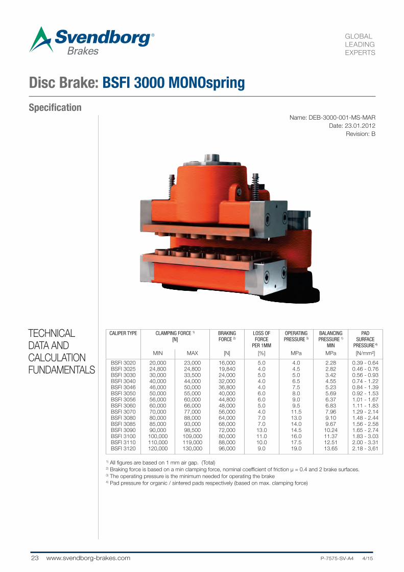
Disc Brake: BSFI 3000 MONOspring
1) All figures are based on 1 mm air gap. (Total)2) Braking force is based on a min clamping force, nominal coefficient of friction μ = 0.4 and 2 brake surfaces.3) The operating pressure is the minimum needed for operating the brake4) Pad pressure for organic / sintered pads respectively (based on max. clamping force)
CALIPER TYPE CLAMPING FORCE 1)
[N]BRAKINGFORCE 2)
LOSS OFFORCE
PER 1MM
OPERATINGPRESSURE 3)
BALANCINGPRESSURE 1)
MIN
PAD SURFACE
PRESSURE 4)
MIN MAX [N] [%] MPa MPa [N/mm²]
BSFI 3020
BSFI 3025
BSFI 3030
BSFI 3040
BSFI 3046
BSFI 3050
BSFI 3056
BSFI 3060
BSFI 3070
BSFI 3080
BSFI 3085
BSFI 3090
BSFI 3100
BSFI 3110
BSFI 3120
20,000
24,800
30,000
40,000
46,000
50,000
56,000
60,000
70,000
80,000
85,000
90,000
100,000
110,000
120,000
23,000
24,800
33,500
44,000
50,000
55,000
60,000
66,000
77,000
88,000
93,000
98,500
109,000
119,000
130,000
16,000
19,840
24,000
32,000
36,800
40,000
44,800
48,000
56,000
64,000
68,000
72,000
80,000
88,000
96,000
5.0
4.0
5.0
4.0
4.0
6.0
6.0
5.0
4.0
7.0
7.0
13.0
11.0
10.0
9.0
4.0
4.5
5.0
6.5
7.5
8.0
9.0
9.5
11.5
13.0
14.0
14.5
16.0
17.5
19.0
2.28
2.82
3.42
4.55
5.23
5.69
6.37
6.83
7.96
9.10
9.67
10.24
11.37
12.51
13.65
0.39 - 0.64
0.46 - 0.76
0.56 - 0.93
0.74 - 1.22
0.84 - 1.39
0.92 - 1.53
1.01 - 1.67
1.11 - 1.83
1.29 - 2.14
1.48 - 2.44
1.56 - 2.58
1.65 - 2.74
1.83 - 3.03
2.00 - 3.31
2.18 - 3,61
TECHNICAL
DATA AND
CALCULATION
FUNDAMENTALS
24P-7575-SV-A4 4/15.... www.svendborg-brakes.com
GLOBAL
LEADING
EXPERTS
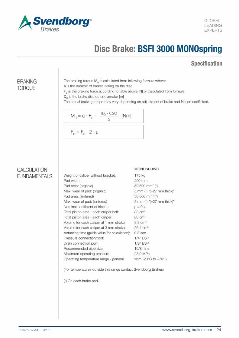
Specification
The braking torque MB is calculated from following formula where:
a is the number of brakes acting on the disc
FB is the braking force according to table above [N] or calculated from formula
DO is the brake disc outer diameter [m]
The actual braking torque may vary depending on adjustment of brake and friction coefficient.
MB = a · F
B · [Nm]
(D0 - 0,20)
2
MONOSPRING
Weight of caliper without bracket: 175 kg
Pad width: 200 mm
Pad area: (organic) 59,600 mm2 (*)
Max. wear of pad: (organic) 5 mm (*) ”(=27 mm thick)”
Pad area: (sintered) 36,000 mm2 (*)
Max. wear of pad: (sintered) 5 mm (*) ”(=27 mm thick)”
Nominal coefficient of friction: μ = 0.4
Total piston area - each caliper half: 88 cm2
Total piston area - each caliper: 88 cm2
Volume for each caliper at 1 mm stroke: 8.8 cm3
Volume for each caliper at 3 mm stroke: 26.4 cm3
Actuating time (guide value for calculation): 0.3 sec
Pressure connection/port: 1/4” BSP
Drain connection port: 1/8” BSP
Recommended pipe size: 10/8 mm
Maximum operating pressure 23.0 MPa
Operating temperature range - general from -20°C to +70°C
(For temperatures outside this range contact Svendborg Brakes)
(*) On each brake pad.
FB = F
C · 2 · μ
Disc Brake: BSFI 3000 MONOspring
BRAKING
TORQUE
CALCULATION
FUNDAMENTALS

25 www.svendborg-brakes.com .....P-7575-SV-A4 4/15
GLOBAL
LEADING
EXPERTS
SpecificationName: DEB-0400-001-DS-MAR
Date: 24.04.2007
Revision: A
Disc Brake: BSFG 400 DUALspring
1) All figures are based on 1 mm air gap. (Each side)2) Braking force is based on a min clamping force, nominal coefficient of friction μ = 0.4 and 2 brake surfaces.3) The operating pressure is the minimum needed for operating the brake4) Pad pressure for organic pads (based on max. clamping force) 5) Not recommended for general usage - special high pressure version
CALIPER TYPE
CLAMPING FORCE 1)
[N]BRAKINGFORCE 3)
LOSS OFFORCE
PER 1MM
OPERATINGPRESSURE 3)
PAD SURFACE
PRESSURE 1)
PAD SURFACE
PRESSURE 4)
MIN MAX [N] [%] MPa MPa [N/mm²]
BSFG 403
BSFG 405
BSFG 408
BSFG 4125)
34,300
55,900
80,100
120,000
38,400
62,600
89,700
134,000
27,500
45,000
64,000
96,000
7.0
6.0
6.0
9.0
7.0
10.5
14.5
22.0
4.60
7.50
10.74
16.09
0.61
0.99
1.42
2.13BSFG 4125) 120,000 134,000 96,000 9.0 22.0 16.09 2.13
TECHNICAL
DATA AND
CALCULATION
FUNDAMENTALS

26P-7575-SV-A4 4/15.... www.svendborg-brakes.com
GLOBAL
LEADING
EXPERTS
Specification
The braking torque MB is calculated from following formula where:
a is the number of brakes acting on the disc
FB is the braking force according to table above [N] or calculated from formula
DO is the brake disc outer diameter [m]
The actual braking torque may vary depending on adjustment of brake and friction coefficient.
MB = a · F
B · [Nm]
(D0 - 0,22)
2
DUALSPRING
Weight of caliper without bracket: Approx. 280 kg
Overall dimensions 520 x 570 x 590 mm
Pad width (width for heat calculation): 220 mm
Pad area: (organic) 63,000 mm2 (*)
Max. wear of pad: (organic) ”11 mm (*) (=14 mm thick - lining)”
Nominal coefficient of friction: μ = 0.4
Total piston area - each caliper half: 74.5 cm2
Total piston area - each caliper: 149 cm2
Volume for each caliper at 1 mm stroke: 15 cm3
Volume for each caliper at 3 mm stroke: 45 cm3
Actuating time (guide value for calculation): 0.4 sec
Pressure connection/port: 3/8” BSP
Drain connection port: 1/4” BSP
Recommended pipe size: 16/12 mm
Maximum operating pressure 23.0 MPa
Operating temperature range - general from -20°C to +70°C
(For temperatures outside this range contact Svendborg Brakes)
(*) On each brake pad.
FB = F
C · 2 · μ
Disc Brake: BSFG 400 DUALspring
BRAKING
TORQUE
CALCULATION
FUNDAMENTALS

27 www.svendborg-brakes.com .....P-7575-SV-A4 4/15
GLOBAL
LEADING
EXPERTS
SpecificationName: DEB-0500-001-DS-MAR
Date: 23.01.2012
Revision: G
Disc Brake: BSFH 500 DUALspring
1) All figures are based on 1 mm air gap. (Each side) 2) Braking force is based on a min clamping force, nominal coefficient of friction μ = 0.4 and 2 brake surfaces.3) The operating pressure is the minimum needed for operating the brake4) Pad pressure for organic / sintered pads respectively (based on max. clamping force)
CALIPER TYPE
CLAMPING FORCE 1)
[N]BRAKINGFORCE 2)
LOSS OFFORCE
PER 1MM
OPERATINGPRESSURE 3)
BALANCINGPRESSURE 1)
MIN
PAD SURFACE
PRESSURE 4)
MIN MAX [N] [%] MPa MPa [N/mm²]
BSFH 507
BSFH 508
BSFH 509
BSFH 510
BSFH 511
BSFH 512
BSFH 514
BSFH 515
BSFH 516
BSFH 520
70,000
80,000
90,000
100,000
110,000
120,000
140,000
150,000
160,000
200,000
74,000
85,000
95,000
105,000
115,000
130,000
153,000
164,000
175,000
218,000
56,000
64,000
72,000
80,000
88,000
96,000
112,000
120,000
128,000
160,000
9.0
7.0
6.0
5.0
4.5
8.0
7.0
6.0
6.0
10.0
8.0
8.5
9.0
10.0
11.0
12.0
14.0
14.5
15.0
19.0
4.82
5.51
6.20
6.89
7.58
8.26
9.64
10.33
11.02
13.77
1.17 - 1.70
1.35 - 1.95
1.51 - 2.18
1.67 - 2.41
1.83 - 2.64
2.06 - 2.98
2.42 - 3.51
2.60 - 3.76
2.78 - 4.01
3.46 - 5.00
TECHNICAL
DATA AND
CALCULATION
FUNDAMENTALS

28P-7575-SV-A4 4/15.... www.svendborg-brakes.com
GLOBAL
LEADING
EXPERTS
Specification
The braking torque MB is calculated from following formula where:
a is the number of brakes acting on the disc
FB is the braking force according to table above [N] or calculated from formula
DO is the brake disc outer diameter [m]
The actual braking torque may vary depending on adjustment of brake and friction coefficient.
MB = a · F
B · [Nm]
(D0 - 0,22)
2
DUALSPRING
Weight of caliper without bracket: Approx. 330 kg
Overall dimensions: 430 x 465 x 490 mm
Pad width (width for heat calculation): 220 mm
Pad area: (organic) 63,000 mm2 (*)
Max. wear of pad: (organic) 10 mm (*) ”(=37 mm thick incl. brake shoe)”
Pad area: (sintered) 43,600 mm2 (*)
Max. wear of pad: (sintered) 5 mm (*) ”(=42 mm thick incl. brake shoe)”
Nominal coefficient of friction: μ = 0.4
Total piston area - each caliper half: 145 cm2
Total piston area - each caliper: 290 cm2
Volume for each caliper at 1 mm stroke: 30 cm3
Volume for each caliper at 3 mm stroke: 90 cm3
Actuating time (guide value for calculation): 0.4 sec
Pressure connection/port: 3/8” BSP
Drain connection port: 1/4” BSP
Recommended pipe size: 16/12 mm
Maximum operating pressure 23.0 MPa
Operating temperature range - general from -20°C to +70°C
(For temperatures outside this range contact Svendborg Brakes)
(*) On each brake pad.
FB = F
C · 2 · μ
Disc Brake: BSFH 500 DUALspring
BRAKING
TORQUE
CALCULATION
FUNDAMENTALS
29 www.svendborg-brakes.com .....P-7575-SV-A4 4/15
GLOBAL
LEADING
EXPERTS
SpecificationName: DEB-0500-001-MS-MAR
Date: 23.01.2012
Revision: G
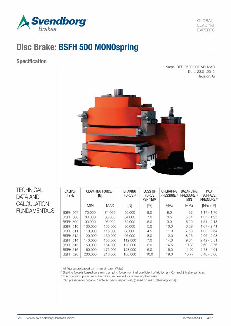
Disc Brake: BSFH 500 MONOspring
1) All figures are based on 1 mm air gab. (Total)2) Braking force is based on a min clamping force, nominal coefficient of friction μ = 0.4 and 2 brake surfaces.3) The operating pressure is the minimum needed for operating the brake4) Pad pressure for organic / sintered pads respectively (based on max. clamping force)
CALIPER TYPE
CLAMPING FORCE 1)
[N]BRAKINGFORCE 2)
LOSS OFFORCE
PER 1MM
OPERATINGPRESSURE 3)
BALANCINGPRESSURE 1)
MIN
PAD SURFACE
PRESSURE 4)
MIN MAX [N] [%] MPa MPa [N/mm²]
BSFH 507
BSFH 508
BSFH 509
BSFH 510
BSFH 511
BSFH 512
BSFH 514
BSFH 515
BSFH 516
BSFH 520
70,000
80,000
90,000
100,000
110,000
120,000
140,000
150,000
160,000
200,000
74,000
85,000
95,000
105,000
115,000
130,000
153,000
164,000
175,000
218,000
56,000
64,000
72,000
80,000
88,000
96,000
112,000
120,000
128,000
160,000
9.0
7.0
6.0
5.0
4.5
8.0
7.0
6.0
6.0
10.0
8.0
8.5
9.0
10.0
11.0
12.0
14.0
14.5
15.0
19.0
4.82
5.51
6.20
6.89
7.58
8.26
9.64
10.33
11.02
13.77
1.17 - 1.70
1.35 - 1.95
1.51 - 2.18
1.67 - 2.41
1.83 - 2.64
2.06 - 2.98
2.42 - 3.51
2.60 - 3.76
2.78 - 4.01
3.46 - 5.00
TECHNICAL
DATA AND
CALCULATION
FUNDAMENTALS

30P-7575-SV-A4 4/15.... www.svendborg-brakes.com
GLOBAL
LEADING
EXPERTS
Specification
The braking torque MB is calculated from following formula where:
a is the number of brakes acting on the disc
FB is the braking force according to table above [N] or calculated from formula
DO is the brake disc outer diameter [m]
The actual braking torque may vary depending on adjustment of brake and friction coefficient.
MB = a · F
B · [Nm]
(D0 - 0,22)
2
MONOSPRING
Weight of caliper without bracket: Approx. 500 kg
Overall dimensions: 720 x 540 x 470 mm
Pad width (width for heat calculation): 220 mm
Pad area: (organic) 63,000 mm2 (*)
Max. wear of pad: (organic) 5 mm (*) ”(=42 mm thick incl. brake shoe)”
Pad area: (sintered) 43,600 mm2 (*)
Max. wear of pad: (sintered) 5 mm (*) ”(=42 mm thick incl. brake shoe)”
Nominal coefficient of friction: μ = 0.4
Total piston area - each caliper half: 145 cm2
Total piston area - each caliper: 145 cm2
Volume for each caliper at 1 mm stroke: 15 cm3
Volume for each caliper at 3 mm stroke: 45 cm3
Actuating time (guide value for calculation): 0.4 sec
Pressure connection/port: 3/8” BSP
Drain connection port: 1/4” BSP
Recommended pipe size: 16/12 mm
Maximum operating pressure 23.0 MPa
Operating temperature range - general from -20°C to +70°C
(For temperatures outside this range contact Svendborg Brakes)
(*) On each brake pad.
FB = F
C · 2 · μ
Disc Brake: BSFH 500 MONOspring
BRAKING
TORQUE
CALCULATION
FUNDAMENTALS

31 www.svendborg-brakes.com .....P-7575-SV-A4 4/15
GLOBAL
LEADING
EXPERTS
SpecificationName: DEB-0500-027-DS-MAR
Date: 23.01.2012
Revision: A
Disc Brake: BSFK 500 DUALspring
1) All figures are based on 1 mm air gap (Each side)2) Braking force is based on a min clamping force, nominal coefficient of friction μ = 0.4 and 2 brake surfaces.3) The operating pressure is the minimum needed for operating the brake4) Pad pressure for organic / sintered pads respectively (based on max. clamping force) 5) Not recommended for general usage
CALIPER TYPE
CLAMPING FORCE 1)
[N]BRAKINGFORCE 2)
LOSS OFFORCE
PER 1MM
OPERATINGPRESSURE 3)
BALANCINGPRESSURE 1)
MIN
PAD SURFACE
PRESSURE4)
MIN MAX [N] [%] MPa MPa [N/mm²]
BSFK 520
BSFK 523
BSFK 525
BSFK 527
BSFK 5305)
BSFK 5355)
200,000
230,000
250,000
270,000
300,000
350,000
220,000
250,000
270,000
295,000
320,000
380,000
160,000
184,000
200,000
216,000
240,000
280,000
5.5
6.5
5.5
5.0
12.5
10.0
13.5
14.0
14.5
15.5
19.0
21.0
8.57
9.86
10.72
11.58
12.86
15.00
3.07 - 3.05
3.48 - 3.45
3.76 - 3.73
4.11 - 4.07
4.46 - 4.42
5.30 - 5.25
BSFK 5305)
BSFK 5355)
300,000
350,000
320,000
380,000
240,000
280,000
12.5
10.0
19.0
21.0
12.86
15.00
4.46 - 4.42
5.30 - 5.25
TECHNICAL
DATA AND
CALCULATION
FUNDAMENTALS

32P-7575-SV-A4 4/15.... www.svendborg-brakes.com
GLOBAL
LEADING
EXPERTS
Specification
The braking torque MB is calculated from following formula where:
a is the number of brakes acting on the disc
FB is the braking force according to table above [N] or calculated from formula
DO is the brake disc outer diameter [m]
The actual braking torque may vary depending on adjustment of brake and friction coefficient.
MB = a · F
B · [Nm]
(D0 - 0,23)
2
DUALSPRING
Weight of caliper without bracket: Approx. 420 kg
Overall dimensions: 720 x 472 x 490 mm
Pad width (width for heat calculation): 230 mm (205 mm)
Pad area: (organic) 71,750 mm2 (*)
Max. wear of pad: (organic) 10 mm (*) ”(=47mm thick)”
Pad area: (sintered) 72,400 mm2 (*)
Max. wear of pad: (sintered) 10 mm (*) ”(=47mm thick)”
Nominal coefficient of friction: μ = 0.4
Total piston area - each caliper half: 233 cm2
Total piston area - each caliper: 466 cm2
Volume for each caliper at 1 mm stroke: 47 cm3
Volume for each caliper at 3 mm stroke: 140 cm3
Actuating time (guide value for calculation): 0.4sec
Pressure connection/port: 3/8” BSP
Drain connection port: 1/4” BSP
Recommended pipe size: 16/12 mm
Maximum operating pressure 23.0 MPa
Operating temperature range - general from -20°C to +70°C
(For temperatures outside this range contact Svendborg Brakes)
(*) On each brake pad.
FB = F
C · 2 · μ
Disc Brake: BSFK 500 DUALspring
BRAKING
TORQUE
CALCULATION
FUNDAMENTALS

33 www.svendborg-brakes.com .....P-7575-SV-A4 4/15
GLOBAL
LEADING
EXPERTS
SpecificationName: DEB-0500-027-MS-MAR
Date: 23.01.2012
Revision: A
Disc Brake: BSFK 500 MONOspring
1) All figures are based on 1 mm air gap (Total)2) Braking force is based on a min clamping force, nominal coefficient of friction μ = 0.4 and 2 brake surfaces.3) The operating pressure is the minimum needed for operating the brake4) Pad pressure for organic / sintered pads respectively (based on max. clamping force) 5) Not recommended for general usage
CALIPER TYPE
CLAMPING FORCE 1)
[N]BRAKINGFORCE 2)
LOSS OFFORCE
PER 1MM
OPERATINGPRESSURE 3)
BALANCINGPRESSURE 1)
MIN
PAD SURFACE
PRESSURE4)
MIN MAX [N] [%] MPa MPa [N/mm²]
BSFK 520
BSFK 523
BSFK 525
BSFK 527
BSFK 5305)
BSFK 5355)
200,000
230,000
250,000
270,000
300,000
350,000
220,000
250,000
270,000
295,000
320,000
380,000
160,000
184,000
200,000
216,000
240,000
280,000
5.5
6.5
5.5
5.5
13.0
11.0
13.5
15.5
15.5
16.0
20.5
23.5
8.57
9.86
10.72
11.58
12.86
15.00
3.07 - 3.05
3.48 - 3.45
3.76 - 3.73
4.11 - 4.07
4.46 - 4.42
5.30 - 5.25
BSFK 5305)
BSFK 5355)
300,000
350,000
320,000
380,000
240,000
280,000
13.0
11.0
20.5
23.5
12.86
15.00
4.46 - 4.42
5.30 - 5.25
TECHNICAL
DATA AND
CALCULATION
FUNDAMENTALS

34P-7575-SV-A4 4/15.... www.svendborg-brakes.com
GLOBAL
LEADING
EXPERTS
Specification
The braking torque MB is calculated from following formula where:
a is the number of brakes acting on the disc
FB is the braking force according to table above [N] or calculated from formula
DO is the brake disc outer diameter [m]
The actual braking torque may vary depending on adjustment of brake and friction coefficient.
MB = a · F
B · [Nm]
(D0 - 0,23)
2
MONOSPRING
Weight of caliper without bracket: Approx. 550 kg
Overall dimensions: 710 x 532 x 565 mm
Pad width (width for heat calculation): 230 mm (205 mm)
Pad area: (organic) 71,750 mm2 (*)
Max. wear of pad: (organic) 5 mm (*) ”(=52mm thick)”
Pad area: (sintered) 72,400 mm2 (*)
Max. wear of pad: (sintered) 5 mm (*) ”(=52mm thick)”
Nominal coefficient of friction: μ = 0.4
Total piston area - each caliper half: 233 cm2
Total piston area - each caliper: 233 cm2
Volume for each caliper at 1 mm stroke: 23 cm3
Volume for each caliper at 3 mm stroke: 70 cm3
Actuating time (guide value for calculation): 0.4sec
Pressure connection/port: 3/8” BSP
Drain connection port: 1/4” BSP
Recommended pipe size: 16/12 mm
Maximum operating pressure 23.0 MPa
Maximum operating pressure BSFK 535 26.0 MPa
Operating temperature range - general from -20°C to +70°C
(For temperatures outside this range contact Svendborg Brakes)
(*) On each brake pad.
FB = F
C · 2 · μ
Disc Brake: BSFK 500 MONOspring
BRAKING
TORQUE
CALCULATION
FUNDAMENTALS
35 www.svendborg-brakes.com .....P-7575-SV-A4 4/15
GLOBAL
LEADING
EXPERTS
SpecificationName: DEB-0600-016-DS-MAR
Date: 24.05.2012
Revision: A
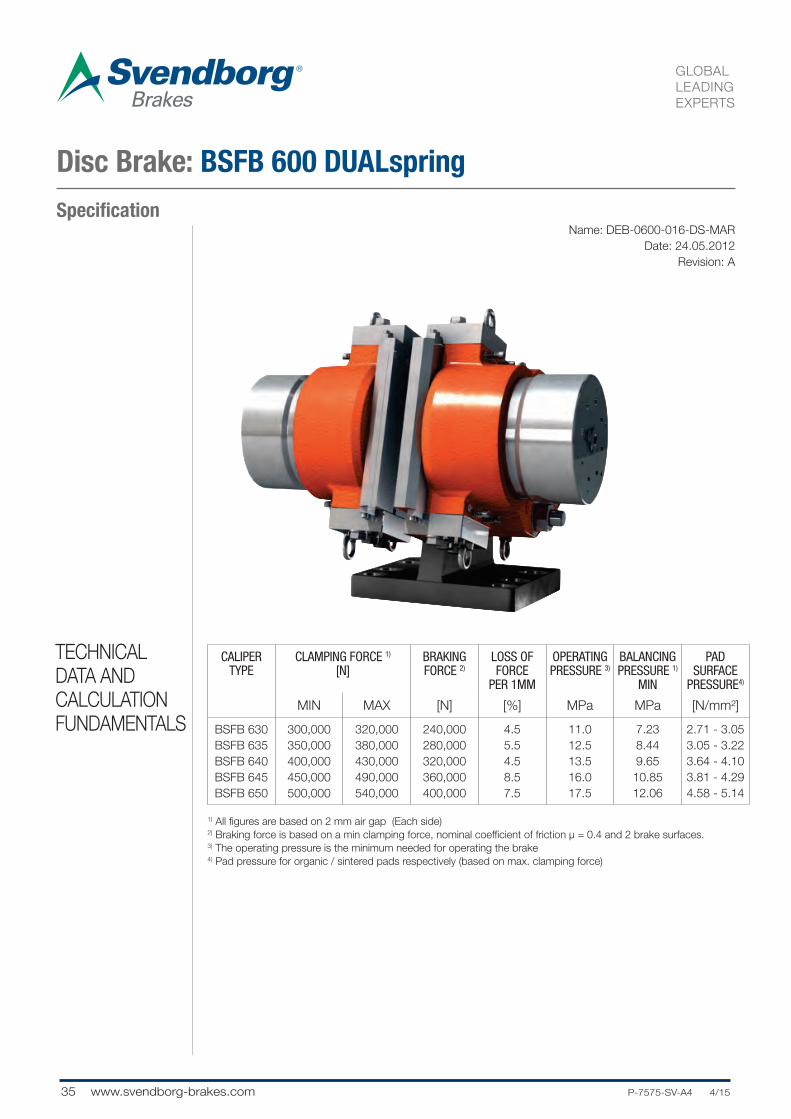
Disc Brake: BSFB 600 DUALspring
1) All figures are based on 2 mm air gap (Each side)2) Braking force is based on a min clamping force, nominal coefficient of friction μ = 0.4 and 2 brake surfaces.3) The operating pressure is the minimum needed for operating the brake4) Pad pressure for organic / sintered pads respectively (based on max. clamping force)
CALIPER TYPE
CLAMPING FORCE 1)
[N]BRAKINGFORCE 2)
LOSS OFFORCE
PER 1MM
OPERATINGPRESSURE 3)
BALANCINGPRESSURE 1)
MIN
PAD SURFACE
PRESSURE4)
MIN MAX [N] [%] MPa MPa [N/mm²]
BSFB 630
BSFB 635
BSFB 640
BSFB 645
BSFB 650
300,000
350,000
400,000
450,000
500,000
320,000
380,000
430,000
490,000
540,000
240,000
280,000
320,000
360,000
400,000
4.5
5.5
4.5
8.5
7.5
11.0
12.5
13.5
16.0
17.5
7.23
8.44
9.65
10.85
12.06
2.71 - 3.05
3.05 - 3.22
3.64 - 4.10
3.81 - 4.29
4.58 - 5.14
TECHNICAL
DATA AND
CALCULATION
FUNDAMENTALS

36P-7575-SV-A4 4/15.... www.svendborg-brakes.com
GLOBAL
LEADING
EXPERTS
Specification
The braking torque MB is calculated from following formula where:
a is the number of brakes acting on the disc
FB is the braking force according to table above [N] or calculated from formula
DO is the brake disc outer diameter [m]
The actual braking torque may vary depending on adjustment of brake and friction coefficient.
MB = a · F
B · [Nm]
(D0 - 0,3)
2
DUALSPRING
Weight of caliper without bracket: Approx. 765 kg
Overall dimensions: 584 x 565 x 797 mm
Pad width (width for heat calculation): 300 mm
Pad area: (organic) 118,000 mm2 (*)
Max. wear of pad: (organic) 10 mm (*) ”(=37 mm thick)”
Pad area: (sintered) 105,000 mm2 (*)
Max. wear of pad: (sintered) 10 mm (*) ”(=37 mm thick)”
Nominal coefficient of friction: μ = 0.4
Total piston area - each caliper half: 415 cm2
Total piston area - each caliper: 830 cm2
Volume for each caliper at 1 mm stroke: 83 cm3
Volume for each caliper at 3 mm stroke: 249 cm3
Actuating time (guide value for calculation): 0.3 - 0,5 sec
Pressure connection/port: 1/2” BSP
Drain connection port: 1/4” BSP
Recommended pipe size: 16 mm
Maximum operating pressure 18.5 MPa
Operating temperature range - general from -20°C to +70°C
(For temperatures outside this range contact Svendborg Brakes)
(C=disc thickness)(*) On each brake pad.
FB = F
C · 2 · μ
Disc Brake: BSFB 600 DUALspring
BRAKING
TORQUE
CALCULATION
FUNDAMENTALS

37 www.svendborg-brakes.com .....P-7575-SV-A4 4/15
GLOBAL
LEADING
EXPERTS
SpecificationName: DEB-0600-016-MS-MAR
Date: 24.05.2012
Revision: A
Disc Brake: BSFB 600 MONOspring
1) All figures are based on 3 mm air gap (Total)2) Braking force is based on a min clamping force, nominal coefficient of friction μ = 0.4 and 2 brake surfaces.3) The operating pressure is the minimum needed for operating the brake4) Pad pressure for organic / sintered pads respectively (based on max. clamping force)
CALIPER TYPE
CLAMPING FORCE 1)
[N]BRAKINGFORCE 2)
LOSS OFFORCE
PER 1MM
OPERATINGPRESSURE 3)
BALANCINGPRESSURE 1)
MIN
PAD SURFACE
PRESSURE4)
MIN MAX [N] [%] MPa MPa [N/mm²]
BSFB 630
BSFB 635
BSFB 638
BSFB 640
300,000
350,000
350,000
400,000
330,000
380,000
380,000
430,000
240,000
280,000
280,000
320,000
7.5
5.0
5.0
4.5
12.5
13.5
13.5
15.0
7.23
8.44
8.44
9.65
2.80 - 3.14
3.05 - 3.22
3.05 - 3.22
3.64 - 4.10
TECHNICAL
DATA AND
CALCULATION
FUNDAMENTALS

38P-7575-SV-A4 4/15.... www.svendborg-brakes.com
GLOBAL
LEADING
EXPERTS
Specification
The braking torque MB is calculated from following formula where:
a is the number of brakes acting on the disc
FB is the braking force according to table above [N] or calculated from formula
DO is the brake disc outer diameter [m]
The actual braking torque may vary depending on adjustment of brake and friction coefficient.
MB = a · F
B · [Nm]
(D0 - 0,3)
2
MONOSPRING
Weight of caliper without bracket: Approx. 850 kg
Overall dimensions: 840 x 620 x 620 mm
Pad width (width for heat calculation): 300 mm
Pad area: (organic) 118,000 mm2 (*)
Max. wear of pad: (organic) 10 mm (*) ”(=37 mm thick)”
Pad area: (sintered) 105,000 mm2 (*)
Max. wear of pad: (sintered) 10 mm (*) ”(=37 mm thick)”
Nominal coefficient of friction: μ = 0.4
Total piston area - each caliper half: 415 cm2
Total piston area - each caliper: 415 cm2
Volume for each caliper at 1 mm stroke: 41 cm3
Volume for each caliper at 3 mm stroke: 124 cm3
Actuating time (guide value for calculation): 0.3 - 0,5 sec
Pressure connection/port: 1/2” BSP
Drain connection port: 1/4” BSP
Recommended pipe size: 16 mm
Maximum operating pressure 18.5 MPa
Operating temperature range - general from -20°C to +70°C
(For temperatures outside this range contact Svendborg Brakes)
(*) On each brake pad.
FB = F
C · 2 · μ
Disc Brake: BSFB 600 MONOspring
BRAKING
TORQUE
CALCULATION
FUNDAMENTALS

39 www.svendborg-brakes.com .....P-7575-SV-A4 4/15
GLOBAL
LEADING
EXPERTS
SpecificationName: DEB-1000-001-MS-MAR
Date: 17.05.2010
Revision: A
Disc Brake: BSFA 1000 MONOspring
1) All figures are based on 2 mm air gap (total) and 2 spring packs.2) Braking force is based on a min clamping force, nominal coefficient of friction μ = 0.4 and 2 brake surfaces.3) The operating pressure is the minimum needed for operating the brake4) Pad pressure for organic / sintered pads respectively (based on max. clamping force)
Bracket is not part of brake.
CALIPER TYPE
CLAMPING FORCE 1)
[N]BRAKINGFORCE 2)
LOSS OFFORCE
PER 1MM
OPERATINGPRESSURE 3)
BALANCINGPRESSURE 1)
MIN
PAD SURFACE
PRESSURE 4)
MIN MAX [N] [%] MPa MPa [N/mm²]
BSFA 1060
BSFA 1070
BSFA 1080
BSFA 1090
BSFA 1100
BSFA 1110
600,000
700,000
800,000
900,000
1.000,000
1.100,000
640,000
740,000
850,000
950,000
1.050,000
1.160,000
480,000
560,000
640,000
720,000
800,000
880,000
8.5
8.5
10.5
9.5
8.5
8.0
13.0
14.0
17.0
18.0
20.5
23.5
7.36
8.58
9.81
11.03
12.26
13.49
4.18
4.84
5.56
6.21
6.86
7.58
TECHNICAL
DATA AND
CALCULATION
FUNDAMENTALS

40P-7575-SV-A4 4/15.... www.svendborg-brakes.com
GLOBAL
LEADING
EXPERTS
Specification
The braking torque MB is calculated from following formula where:
a is the number of brakes acting on the disc
FB is the braking force according to table above [N] or calculated from formula
DO is the brake disc outer diameter [m]
The actual braking torque may vary depending on adjustment of brake and friction coefficient.
MB = a · F
B · [Nm]
(D0 - 0,3)
2
Weight of complete caliper
incl. pads and without bracket: 1,400 - 1600 kg depending on the disc thickness
Disc thickness: 80 - 135 mm (depending on type)
Overall caliper dimensions: 766 - 859 x 800 x 615mm (depending on disc thickness)
Pad width: 300 mm
Pad friction area: (organic) 153,000 mm2 (1)
Max. wear of pad: 5 mm (1)
Nominal coefficient of friction: μ = 0.4
Total piston area - each caliper half: 2 x 40,800 mm2 = 81,600 mm2
Volume for each caliper half at 1 mm stroke: 81.6 cm3
Volume for each caliper at 3 mm stroke: 245 cm3
Actuating time (guide value for calculation): 0.4sec
Pressure connection (port size): 3/4” BSP
Drain connection R (port size): 1/4” BSP
Recommended hydraulic pipe size OD: 16 mm
Max. operating pressure 23,0 MPa
Operating temperature range - general from -20°C to +70°C
(For temperatures outside this range contact Svendborg Brakes)
(*) On each brake pad.
FB = F
C · 2 · μ
Disc Brake: BSFA 1000 MONOspring
BRAKING
TORQUE
CALCULATION
FUNDAMENTALS

41 www.svendborg-brakes.com .....P-7575-SV-A4 4/15
GLOBAL
LEADING
EXPERTS
SpecificationName: DEB-0075-002-DA-MAR
Date: 07.03.2008
Revision: A
Disc Brake: BSAB 75 DUAL-ACTION
TECHNICAL
DATA AND
CALCULATION
FUNDAMENTALS

42P-7575-SV-A4 4/15.... www.svendborg-brakes.com
GLOBAL
LEADING
EXPERTS
Specification
The braking torque MB is calculated from following formula where:
a is the number of brakes acting on the disc
FB is the braking force according to table above [N] or calculated from formula
DO is the brake disc outer diameter [m]
FC is the clamping force [N]
A [cm2], P [bar] and μ see values below
The actual braking torque may vary depending on friction coefficient.
Weight of caliper without bracket: Approx. 60 kg
Overall dimensions: 220 x 240 x 260 mm
Pad width: 102 mm
Pad area: (organic) 20,300 mm2 (*)
Max. wear of pad: (organic) 7 mm (*) ”(=11 mm thick)”
Pad area: (sinter) 16,350 mm2 (*)
Max. wear of pad: (sinter) 6 mm (*) ”(=12 mm thick)”
Nominal coefficient of friction: μ = 0.4
Total piston area - each caliper half: A=88 cm2
Total piston area - each caliper: 176 cm2
Volume for each caliper at 1 mm stroke: 18 cm3
Volume for each caliper at 3 mm stroke: 54 cm3
Actuating time (guide value for calculation): 0.4 sec
Pressure connection/port: 1/4” BSP
Drain connection/port: 1/4” BSP
Max. operating pressure: 16 MPa
Recommended pipe size: 10/8 mm
Operating temperature range - general from -20°C to +70°C
Operating temperature range - wind turbine from -40°C to +60°C
(For temperatures outside this range contact Svendborg Brakes)
(*) On each brake pad.
MB = a · F
B · [Nm]
(D0 - 0,102)
2
FB = F
C · 2 · μ [N] F
C = A
· P · 10 [N]
Disc Brake: BSAB 75 DUAL-ACTION
BRAKING
TORQUE
CALCULATION
FUNDAMENTALS

43 www.svendborg-brakes.com .....P-7575-SV-A4 4/15
GLOBAL
LEADING
EXPERTS
SpecificationName: DEB-0090-001-DA-MAR
Date: 09.12.2009
Revision: B
Disc Brake: BSAB 90 DUAL-ACTION
TECHNICAL
DATA AND
CALCULATION
FUNDAMENTALS

44P-7575-SV-A4 4/15.... www.svendborg-brakes.com
GLOBAL
LEADING
EXPERTS
Specification
The braking torque MB is calculated from following formula where:
a is the number of brakes acting on the disc
FB is the braking force according to table above [N] or calculated from formula
DO is the brake disc outer diameter [m]
FC is the clamping force [N]
A [cm2], P [bar] and μ see values below
The actual braking torque may vary depending on friction coefficient.
Weight of caliper without bracket: Approx. 60 kg
Overall dimensions: 220 x 240 x 260 mm
Pad width: 102 mm
Pad area: (organic) 20,300 mm2 (*)
Max. wear of pad: (organic) 7 mm (*) ”(=14 mm thick)”
Pad area: (sinter) 16,350 mm2 (*)
Max. wear of pad: (sinter) 6 mm (*) ”(=12 mm thick)”
Nominal coefficient of friction: μ = 0.4
Total piston area - each caliper half: A=127 cm2
Total piston area - each caliper: 254 cm2
Volume for each caliper at 1 mm stroke: 25 cm3
Volume for each caliper at 3 mm stroke: 76 cm3
Actuating time (guide value for calculation): 0.4 sec
Pressure connection/port: 1/4” BSP
Drain connection/port: 1/4” BSP
Max. operating pressure: 15.7 MPa
Recommended pipe size: 10/8 mm
Operating temperature range - general from -20°C to +70°C
Operating temperature range - wind turbine from -40°C to +60°C
(For temperatures outside this range contact Svendborg Brakes)
(*) On each brake pad.
MB = a · F
B · [Nm]
(D0 - 0,102)
2
FB = F
C · 2 · μ [N] F
C = A
· P · 10 [N]
Disc Brake: BSAB 90 DUAL-ACTION
BRAKING
TORQUE
CALCULATION
FUNDAMENTALS

45 www.svendborg-brakes.com .....P-7575-SV-A4 4/15
GLOBAL
LEADING
EXPERTS
SpecificationName: DEB-0120-001-DA-MAR
Date: 03.12.2009
Revision: B
Disc Brake: BSAB 120 DUAL-ACTION
TECHNICAL
DATA AND
CALCULATION
FUNDAMENTALS

46P-7575-SV-A4 4/15.... www.svendborg-brakes.com
GLOBAL
LEADING
EXPERTS
Specification
The braking torque MB is calculated from following formula where:
a is the number of brakes acting on the disc
FB is the braking force according to table above [N] or calculated from formula
DO is the brake disc outer diameter [m]
FC is the clamping force [N]
A [cm2], P [bar] and μ see values below
The actual braking torque may vary depending on friction coefficient.
Weight of caliper without braket: Approx. 210 kg
Overall dimensions: 500 x 310 x 274 mm
Pad width: 138 mm
Pad area: (organic) 50,000 mm2 (*)
Max. wear of pad: (organic) 7 mm (*) ”(=14 mm thick)”
Nominal coefficient of friction: μ = 0.4
Total piston area - each caliper half: A=339.3 cm2
Total piston area - each caliper: 678.6 cm2
Volume for each caliper at 1 mm stroke: 67.86 cm3
Volume for each caliper at 3 mm stroke: 203.5 cm3
Actuating time (guide value for calculation): 0.8 sec
Pressure connection/port: 1/4” BSP
Drain connection/port: 1/4” BSP
Max. operating pressure: 16.0 MPa
Recommended pipe size: 10 mm
Operating temperature range - general from -20°C to +70°C
Operating temperature range - wind turbine from -40°C to +60°C
(For temperatures outside this range contact Svendborg Brakes)
(*) On each brake pad.
MB = a · F
B · [Nm]
(D0 - 0,136)
2
FB = F
C · 2 · μ [N] F
C = A
· P · 10 [N]
Disc Brake: BSAB 120 DUAL-ACTION
BRAKING
TORQUE
CALCULATION
FUNDAMENTALS

47 www.svendborg-brakes.com .....P-7575-SV-A4 4/15
GLOBAL
LEADING
EXPERTS
SpecificationName: DEB-0300-043-DA-MAR
Date: 15.05.2009
Revision: A
Disc Brake: BSAK 300 DUAL-ACTION
TECHNICAL
DATA AND
CALCULATION
FUNDAMENTALS

48P-7575-SV-A4 4/15.... www.svendborg-brakes.com
GLOBAL
LEADING
EXPERTS
Specification
DUAL-ACTION
Weight of caliper without bracket: Approx. 55 kg
Overall dimensions: 331 x 320 x 321 mm
Pad width: 130 mm
Pad area: (organic) 29,000 mm2 (*)
Max. wear of pad: (organic) 10 mm (*) ”(=14 mm thick)”
Pad area: (sinter) 20,000 mm2 (*)
Max. wear of pad: (sinter) 7 mm (*) ”(=17 mm thick)”
Nominal coefficient of friction: μ = 0.4
Total piston area - each caliper half: A=44.2 cm2
Total piston area - each caliper: 88.4 cm2
Volume for each caliper at 1 mm stroke: 8.8 cm3
Volume for each caliper at 3 mm stroke: 24.6 cm3
Actuating time (guide value for calculation): 0.3 sec
Pressure connection/port: 1/4” BSP
Drain connection/port: 1/8” BSP
Max. operating pressure: 12.5 MPa
Recommended pipe size: 10/8 mm
Operating temperature range - general from -20°C to +70°C
Operating temperature range - wind turbine from -40°C to +60°C
(For temperatures outside this range contact Svendborg Brakes)
(*) On each brake pad.
The braking torque MB is calculated from following formula where:
a is the number of brakes acting on the disc
FB is the braking force according to table above [N] or calculated from formula
DO is the brake disc outer diameter [m]
FC is the clamping force [N]
A [cm2], P [bar] and μ see values below
The actual braking torque may vary depending on friction coefficient.
MB = a · F
B · [Nm]
(D0 - 0,13)
2
FB = F
C · 2 · μ [N] F
C = A
· P · 10 [N]
Disc Brake: BSAK 300 DUAL-ACTION
BRAKING
TORQUE
CALCULATION
FUNDAMENTALS

49 www.svendborg-brakes.com .....P-7575-SV-A4 4/15
GLOBAL
LEADING
EXPERTS
SpecificationName: DEB-0300-043-DA-MAR
Date: 15.05.2009
Revision: A
Disc Brake: BSAK 300 MONO-ACTION
TECHNICAL
DATA AND
CALCULATION
FUNDAMENTALS

50P-7575-SV-A4 4/15.... www.svendborg-brakes.com
GLOBAL
LEADING
EXPERTS
Specification
MONO-ACTION
Weight of caliper without bracket: Approx. 75 kg
Overall dimensions: 260 x 420 x 300 mm
Pad width: 130 mm
Pad area: (organic) 29,000 mm2 (*)
Max. wear of pad: (organic) 5 mm (*) ”(=19 mm thick)”
Pad area: (sinter) 20,000 mm2 (*)
Max. wear of pad: (sinter) 5 mm (*) ”(=19 mm thick)”
Nominal coefficient of friction: μ = 0.4
Total piston area - each caliper half: A=44.2 cm2
Total piston area - each caliper: 44.2 cm2
Volume for each caliper at 1 mm stroke: 4.4 cm3
Volume for each caliper at 3 mm stroke: 13.2 cm3
Actuating time (guide value for calculation): 0.3 sec
Pressure connection/port: 1/4” BSP
Drain connection/port: 1/8” BSP
Max. operating pressure: 12.5 MPa
Recommended pipe size: 10/8 mm
Operating temperature range - general from -20°C to +70°C
Operating temperature range - wind turbine from -40°C to +60°C
(For temperatures outside this range contact Svendborg Brakes)
(*) On each brake pad.
The braking torque MB is calculated from following formula where:
a is the number of brakes acting on the disc
FB is the braking force according to table above [N] or calculated from formula
DO is the brake disc outer diameter [m]
FC is the clamping force [N]
A [cm2], P [bar] and μ see values below
The actual braking torque may vary depending on friction coefficient.
MB = a · F
B · [Nm]
(D0 - 0,13)
2
FB = F
C · 2 · μ [N] F
C = A
· P · 10 [N]
Disc Brake: BSAK 300 MONO-ACTION
BRAKING
TORQUE
CALCULATION
FUNDAMENTALS

51 www.svendborg-brakes.com .....P-7575-SV-A4 4/15
GLOBAL
LEADING
EXPERTS
SpecificationName: DEB-3000-020-DA-MAR
Date: 15.05.2009
Revision: A
Disc Brake: BSAK 3000 DUAL-ACTION
TECHNICAL
DATA AND
CALCULATION
FUNDAMENTALS

52P-7575-SV-A4 4/15.... www.svendborg-brakes.com
GLOBAL
LEADING
EXPERTS
Specification
DUAL-ACTION
Weight of caliper without bracket: Approx. 130 kg
Pad width: 200 mm
Pad area: (organic) 59,600 mm2 (*)
Max. wear of pad: (organic) 10 mm (*) ”(=22 mm thick)”
Pad area: (sinter) 36,000 mm2 (*)
Max. wear of pad: (sinter) 10 mm (*) ”(=22 mm thick)”
Nominal coefficient of friction: μ = 0.4
Total piston area - each caliper half: A=113.1 cm2
Total piston area - each caliper: 226.2 cm2
Volume for each caliper at 1 mm stroke: 22.6 cm3
Volume for each caliper at 3 mm stroke: 67.9 cm3
Actuating time (guide value for calculation): 0.3 sec
Pressure connection/port: 1/4” BSP
Max. operating pressure: 11.5 MPa
Operating temperature range - general from -20°C to +70°C
Operating temperature range - wind turbine from -40°C to +60°C
(For temperatures outside this range contact Svendborg Brakes)
(*) On each brake pad.
The braking torque MB is calculated from following formula where:
a is the number of brakes acting on the disc
FB is the braking force according to table above [N] or calculated from formula
DO is the brake disc outer diameter [m]
FC is the clamping force [N]
A [cm2], P [bar] and μ see values below
The actual braking torque may vary depending on friction coefficient.
MB = a · F
B · [Nm]
(D0 - 0,2)
2
FB = F
C · 2 · μ [N] F
C = A
· P · 10 [N]
Disc Brake: BSAK 3000 DUAL-ACTION
BRAKING
TORQUE
CALCULATION
FUNDAMENTALS

53 www.svendborg-brakes.com .....P-7575-SV-A4 4/15
GLOBAL
LEADING
EXPERTS
SpecificationName: DEB-0300-043-DA-MAR
Date: 15.05.2009
Revision: A
Disc Brake: BSAK 3000 MONO-ACTION
TECHNICAL
DATA AND
CALCULATION
FUNDAMENTALS

54P-7575-SV-A4 4/15.... www.svendborg-brakes.com
GLOBAL
LEADING
EXPERTS
Specification
MONO-ACTION
Weight of caliper without bracket: Approx. 160 kg
Pad width: 200 mm
Pad area: (organic) 59,600 mm2 (*)
Max. wear of pad: (organic) 5 mm (*) ”(=23 mm thick)”
Pad area: (sinter) 36,000 mm2 (*)
Max. wear of pad: (sinter) 5 mm (*) ”(=23 mm thick)”
Nominal coefficient of friction: μ = 0.4
Total piston area - each caliper half: A=113.1 cm2
Total piston area - each caliper: 113.1 cm2
Volume for each caliper at 1 mm stroke: 11.31 cm3
Volume for each caliper at 3 mm stroke: 33.9 cm3
Actuating time (guide value for calculation): 0.3 sec
Pressure connection/port: 1/4” BSP
Max. operating pressure: 11.5 MPa
Operating temperature range - general from -20°C to +70°C
Operating temperature range - wind turbine from -40°C to +60°C
(For temperatures outside this range contact Svendborg Brakes)
(*) On each brake pad.
The braking torque MB is calculated from following formula where:
a is the number of brakes acting on the disc
FB is the braking force according to table above [N] or calculated from formula
DO is the brake disc outer diameter [m]
FC is the clamping force [N]
A [cm2], P [bar] and μ see values below
The actual braking torque may vary depending on friction coefficient.
MB = a · F
B · [Nm]
(D0 - 0,2)
2
FB = F
C · 2 · μ [N] F
C = A
· P · 10 [N]
Disc Brake: BSAK 3000 MONO-ACTION
BRAKING
TORQUE
CALCULATION
FUNDAMENTALS

55 www.svendborg-brakes.com .....P-7575-SV-A4 4/15
GLOBAL
LEADING
EXPERTS
SpecificationName: DEB-3000-030-MA-MAR
Date: 07.03.2012
Revision: -
Disc Brake: BSAL 3000 MONO-ACTION
TECHNICAL
DATA AND
CALCULATION
FUNDAMENTALS

56P-7575-SV-A4 4/15.... www.svendborg-brakes.com
GLOBAL
LEADING
EXPERTS
Specification
MONO-ACTION
Weight of caliper without bracket: Approx. 180 kg
Pad width: 200 mm
Pad area: (organic) 59,600 mm2 (*)
Max. wear of pad: (organic) 5 mm (*) ”(=23 mm thick)”
Pad area: (sinter) 36,000 mm2 (*)
Max. wear of pad: (sinter) 5 mm (*) ”(=23 mm thick)”
Nominal coefficient of friction: μ = 0.4
Total piston area - each caliper half: A=113.1 cm2
Total piston area - each caliper: 113.1 cm2
Volume for each caliper at 1 mm stroke: 11.31 cm3
Volume for each caliper at 3 mm stroke: 33.9 cm3
Actuating time (guide value for calculation): 0.3 sec
Pressure connection/port: 1/4” BSP, 1/8” BSP
Max. operating pressure: 11.5 MPa
Operating temperature range - general from -20°C to +70°C
Operating temperature range - wind turbine from -40°C to +60°C
(For temperatures outside this range contact Svendborg Brakes)
(*) On each brake pad.
The braking torque MB is calculated from following formula where:
a is the number of brakes acting on the disc
FB is the braking force according to table above [N] or calculated from formula
DO is the brake disc outer diameter [m]
FC is the clamping force [N]
A [cm2], P [bar] and μ see values below
The actual braking torque may vary depending on adjustment of brake and friction coefficient.
MB = a · F
B · [Nm]
(D0 - 0,2)
2
FB = F
C · 2 · μ [N] F
C = A
· P · 10 [N]
Disc Brake: BSAL 3000 MONO-ACTION
BRAKING
TORQUE
CALCULATION
FUNDAMENTALS

57 www.svendborg-brakes.com .....P-7575-SV-A4 4/15
GLOBAL
LEADING
EXPERTS
SpecificationName: DEB-0120-004-DA-MAR
Date: 03.07.2012
Revision: -
Disc Brake: BSAC 120 DUAL-ACTION
TECHNICAL
DATA AND
CALCULATION
FUNDAMENTALS

58P-7575-SV-A4 4/15.... www.svendborg-brakes.com
GLOBAL
LEADING
EXPERTS
Specification
DUAL-ACTION
Weight of caliper without bracket: Approx. 850 kg
Overall dimensions: 572 x 318 x 278 mm
Pad width: 138 mm
Pad area:(organic) 58,500 mm2 (*)
Max. wear of pad:(organic) 7 mm (*) ”(=14 mm thick)”
Nominal coefficient of friction: μ= 0.4
Total piston area - each caliper half: A=339,3 cm2
Total piston area - each caliper: 678,6 cm2
Volume for each caliper at 1 mm stroke: 67,8 cm3
Volume for each caliper at 3 mm stroke: 203,5 cm3
Actuating time (guide value for calculation): 0.8 sec
Pressure connection/port: 1/4” BSP
Drain connection port: 1/4” BSP
Max. operating pressure Pmax 20.5 MPa
Min. operating pressure Pmin 9.0 MPa
Recommended pipe size: 10 mm
Operating temperature range - general from -20°C to +70°C
Operating temperature range - wind turbine from -40°C to +60°C
(For temperatures outside this range contact Svendborg Brakes)
(*) On each brake pad.
The braking torque MB is calculated from following formula where:
a is the number of brakes acting on the disc
FB is the braking force according to table above [N] or calculated from formula
DO is the brake disc outer diameter [m]
FC is the clamping force [N]
A [cm2], P [bar] and μ see values below
The actual braking torque may vary depending on friction coefficient.
MB = a · F
B · [Nm]
(D0
- 0,136)
2
FB = F
C · 2 · μ [N] F
C = A
· P · 10 [N]
Disc Brake: BSAC 120 DUAL-ACTION
BRAKING
TORQUE
CALCULATION
FUNDAMENTALS

59 www.svendborg-brakes.com .....P-7575-SV-A4 4/15
GLOBAL
LEADING
EXPERTS
SpecificationName: DEB-0060-001- MAR
Date: 10.09.2012
Revision: -
Disc Brake: YSAA 60
TECHNICAL
DATA AND
CALCULATION
FUNDAMENTALS

60P-7575-SV-A4 4/15.... www.svendborg-brakes.com
GLOBAL
LEADING
EXPERTS
Specification
Weight of caliper without bracket incl. pads: Approx. 51 kg
Overall dimensions: 171 x 265 x 278 mm
Pad diameter: 3x 63 mm + 2x 93 mm
Pad area: 9,352 mm2 + 13,586 mm2
Max. wear of Slide/brake material: TBD
Nominal coefficient of friction: μ= 0.4
Total piston area - each caliper: 85 cm2
Volume for each caliper at 1 mm stroke: 8,5 cm3
Actuating time (guide value for calculation): 0.4 sec
Pressure connection/port: 1/4” BSP
Drain connection port: 1/8” BSP
Max. operating pressure: 200 bar
Recommended pipe size: 8-10 mm
Operating temperature range - general from -40°C to +70°C
Operating temperature range - wind turbine from -40°C to +60°C
(For temperatures outside this range contact Svendborg Brakes)
The braking torque MB is calculated from following formula where:
a is the number of brakes acting on the disc
FB is the braking force according to table above [N]
DO is the brake disc outer diameter [m]
FC is the clamping force [N]
A [cm2], P [bar] and μ see values below
The actual braking torque may vary depending on friction coefficient.
MB = a · F
B · [Nm]
(D0
- 0,102)
2
FB = F
C · 2 · μ [N] F
C = A
· P · 10 [N]
Disc Brake: YSAA 60
BRAKING
TORQUE
CALCULATION
FUNDAMENTALS

61 www.svendborg-brakes.com .....P-7575-SV-A4 4/15
GLOBAL
LEADING
EXPERTS
Notes:

GLOBAL
LEADING
EXPERTS
SVENDBORG NEW BRAKESSvendborg Brakes is the global market leader in intelligent braking solutions. This is why.

63 www.svendborg-brakes.com .....P-7575-SV-A4 4/15
GLOBAL
LEADING
EXPERTS
SpecificationName: DEB-0500-029-DS-MAR
Date: 20.05.2013
Revision: -
Disc Brake: BSFH D500 (DOUBLE PISTON) DUALspring
1) All figures are based on 1 mm air gap (Total) and 2 spring packs2) Braking force is based on a min clamping force, nominal coefficient of friction μ = 0.4 and 2 brake surfaces.3) The piston travel at which the pressure limits is measured - the norminal pressure limits is identical to balancing pressure
values 5) Pad pressure for organic pads respectively (based on max. clamping force)
CALIPER TYPE CLAMPING FORCE 1)
[N]BRAKINGFORCE 2)
LOSS OFFORCE
PER 1MM
OPERATINGPRESSURE 3)
BALANCINGPRESSURE 1)
MIN
PAD SURFACE
PRESSURE 5)
MIN MAX [N] [%] MPa MPa [N/mm²]
BSFH D524
BSFH D528
BSFH D530
BSFH D532
BSFH D540
240,000
280,000
300,000
320,000
400,000
260,000
306,000
328,000
350,000
436,000
192,000
224,000
240,000
256,000
320,000
8.0
7.0
6.0
6.0
10.0
12.0
14.0
14.5
15.0
19.0
8.3
9.7
10.3
11.0
13.8
2.4
2.8
3.0
3.2
4.0
TECHNICAL
DATA AND
CALCULATION
FUNDAMENTALS

64P-7575-SV-A4 4/15.... www.svendborg-brakes.com
GLOBAL
LEADING
EXPERTS
Specification
The braking torque MB is calculated from following formula where:
a is the number of brakes acting on the disc
FB is the braking force according to table above [N] or calculated from formula
DO is the brake disc outer diameter [m]
The actual braking torque may vary depending on adjustment of brake and friction coefficient.
MB = a · F
B · [Nm]
(D0 - 0,2)
2
DUALSPRING
Weight of caliper without bracket: Approx. 780 kg
Overall dimensions without base plate: 698 x 530 x 533 (+C) mm
Pad width: 200 mm
Pad area: (organic) 110,000 mm2 (*)
Max. wear of pad: (organic) 10 mm (*)
Nominal coefficient of friction: μ = 0.4
Total piston area - each caliper half: 2 x 145 cm2 = 290 cm2
Total piston area - each caliper: 4 x 145 cm2 = 580 cm2
Volume for each caliper at 1 mm stroke: 60 cm3
Volume for each caliper at 3 mm stroke: 180 cm3
Actuating time (guide value for calculation): 0.4sec
Pressure connection/P-port: G3/8, ISO 288
Air breathing connection/A-port: G3/8, ISO 288
Drain connection/L-port: G1/4, ISO 288
Recommended pipe size: 16/12 mm
Operating temperature range - general from -20°C to +70°C
(For temperatures outside this range contact Svendborg Brakes)(C = Brake disc thickness)(*) On each brake pad.
FB = F
C · 2 · μ
Disc Brake: BSFH D500 (DOUBLE PISTON) DUALspring
BRAKING
TORQUE
CALCULATION
FUNDAMENTALS

65 www.svendborg-brakes.com .....P-7575-SV-A4 4/15
GLOBAL
LEADING
EXPERTS
SpecificationName: DEB-0500-029-MS-MAR
Date: 20.05.2013
Revision: -
Disc Brake: BSFH D500 (DOUBLE PISTON) MONOspring
1) All figures are based on 1 mm air gap (Total) and 2 spring packs2) Braking force is based on a min clamping force, nominal coefficient of friction μ = 0.4 and 2 brake surfaces.3) The piston travel at which the pressure limits is measured - the norminal pressure limits is identical to balancing pressure
values 5) Pad pressure for organic pads respectively (based on max. clamping force)
CALIPER TYPE CLAMPING FORCE 1)
[N]BRAKINGFORCE 2)
LOSS OFFORCE
PER 1MM
OPERATINGPRESSURE 3)
BALANCINGPRESSURE 1)
MIN
PAD SURFACE
PRESSURE 5)
MIN MAX [N] [%] MPa MPa [N/mm²]
BSFH D524
BSFH D528
BSFH D530
BSFH D532
BSFH D540
240,000
280,000
300,000
320,000
400,000
260,000
306,000
328,000
350,000
436,000
192,000
224,000
240,000
256,000
320,000
8.0
7.0
6.0
6.0
10.0
12.0
14.0
14.5
15.0
19.0
8.3
9.7
10.3
11.0
13.8
2.4
2.8
3.0
3.2
4.0
TECHNICAL
DATA AND
CALCULATION
FUNDAMENTALS

66P-7575-SV-A4 4/15.... www.svendborg-brakes.com
GLOBAL
LEADING
EXPERTS
Specification
The braking torque MB is calculated from following formula where:
a is the number of brakes acting on the disc
FB is the braking force according to table above [N] or calculated from formula
DO is the brake disc outer diameter [m]
The actual braking torque may vary depending on adjustment of brake and friction coefficient.
MB = a · F
B · [Nm]
(D0 - 0,2)
2
MONOSPRING
Weight of caliper without bracket: Approx. 910 - 1100 kg
Overall dimensions without base plate: 698 x 530 x 351 (+C) mm
Pad width: 200 mm
Pad area: (organic) 110,000 mm2 (*)
Max. wear of pad: (organic) 5 mm (*)
Nominal coefficient of friction: μ = 0.4
Total piston area - each caliper half: 2 x 145 cm2 = 290 cm2
Total piston area - each caliper: 2 x 145 cm2 = 290 cm2
Volume for each caliper at 1 mm stroke: 30 cm3
Volume for each caliper at 3 mm stroke: 90 cm3
Actuating time (guide value for calculation): 0.4sec
Pressure connection/P-port: G3/8, ISO 288
Air breathing connection/A-port: G3/8, ISO 288
Drain connection/L-port: G1/4, ISO 288
Recommended pipe size: 16/12 mm
Operating temperature range - general from -20°C to +70°C
(For temperatures outside this range contact Svendborg Brakes)(C = Brake disc thickness)(*) On each brake pad.
FB = F
C · 2 · μ
Disc Brake: BSFH D500 (DOUBLE PISTON) MONOspring
BRAKING
TORQUE
CALCULATION
FUNDAMENTALS

67 www.svendborg-brakes.com .....P-7575-SV-A4 4/15
GLOBAL
LEADING
EXPERTS
SpecificationName: DEB-0500-030-DA-MAR
Date: 20.05.2013
Revision: -
Disc Brake: BSAH D500 (DOUBLE PISTON) DUAL-ACTION
TECHNICAL
DATA AND
CALCULATION
FUNDAMENTALS

68P-7575-SV-A4 4/15.... www.svendborg-brakes.com
GLOBAL
LEADING
EXPERTS
Specification
DUAL-ACTION
Weight of caliper without bracket: Approx. 780 kg
Overall dimensions excl. base plate: 698 x 530 x 533 (+C) mm
Pad width: 200 mm
Pad area:(organic) 110,000 mm2 (*)
Max. wear of pad:(organic) 8 mm (*)
Nominal coefficient of friction: μ = 0.4
Total piston area - each caliper half ”A” (active braking): 2 x 145 cm2 = 290 cm2
Total piston area - each caliper ”A” (active braking): 4 x 145 cm2 = 580 cm2
Total piston area - each caliper half ”A” (retraction): 2 x 145 cm2 = 290 cm2
Total piston area - each caliper ”A” (retractio): 4 x 145 cm2 = 580 cm2
Volume for each caliper at 1 mm stroke (active braking): 60 cm3
Volume for each caliper at 3 mm stroke (active braking): 180 cm3
Volume for each caliper at 1 mm stroke (retraction): 60 cm3
Volume for each caliper at 3 mm stroke (retraction): 180 cm3
Actuating time (guide value for calculation): 0.4 sec
Active pressure connection size (A-port): G3/8, ISO 228
Retraction connection size (P-port): G3/8, ISO 228
Drain connection size (L-port): G1/4, ISO 228
Max. operating pressure Pmax 15.0 MPa (150 bar)
Recommended pipe size: 16/12 mm
Operating temperature range - general from -20°C to +70°C
(For temperatures outside this range contact Svendborg Brakes)(C= Brake disc thickness)(*) On each brake pad.
The braking torque MB is calculated from following formula where:
a is the number of brakes acting on the disc
FB is the braking force [N]
DO is the brake disc outer diameter [m]
FC is the clamping force [N]
Fr is the piston retraction force [N]
A is the active piston area[cm2]
Ar is the retraction piston area[cm2]
P is the hydraulic pressure[bar]
Pr is the hydraulic retraction pressure[bar
μ is the coefficient of friction - see values below
The actual braking torque may vary depending on adjustment of brake and friction coefficient.
MB = a · F
B · [Nm]
(D0
- 0,2)
2
FB = (F
C-F
r) · 2 · μ [N]
(valid for FC>F
R)
FC = A
· P · 10 [N] F
r = A
r · P
r · 10 [N]
Disc Brake: BSAH D500 (DOUBLE PISTON) DUAL-ACTION
BRAKING
TORQUE
CALCULATION
FUNDAMENTALS

69 www.svendborg-brakes.com .....P-7575-SV-A4 4/15
GLOBAL
LEADING
EXPERTS
SpecificationName: DEB-0500-030-MA-MAR
Date: 20.05.2013
Revision: -
Disc Brake: BSAH D500 (DOUBLE PISTON) MONO-ACTION
TECHNICAL
DATA AND
CALCULATION
FUNDAMENTALS
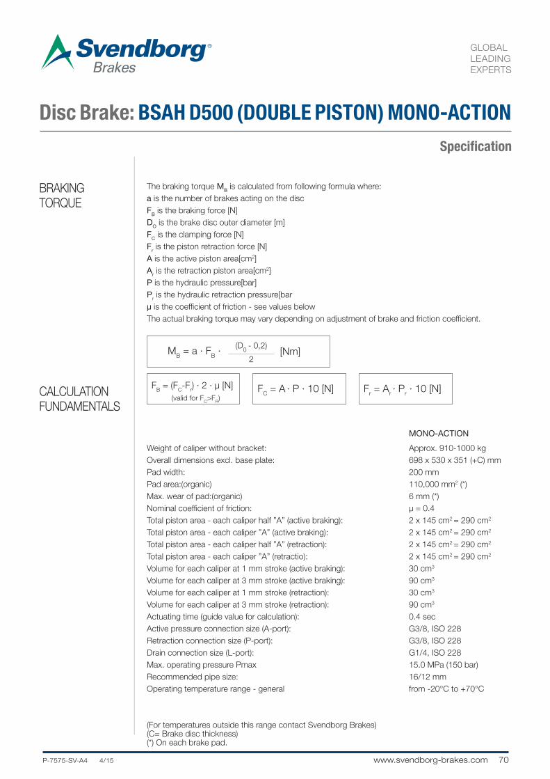
70P-7575-SV-A4 4/15.... www.svendborg-brakes.com
GLOBAL
LEADING
EXPERTS
Specification
MONO-ACTION
Weight of caliper without bracket: Approx. 910-1000 kg
Overall dimensions excl. base plate: 698 x 530 x 351 (+C) mm
Pad width: 200 mm
Pad area:(organic) 110,000 mm2 (*)
Max. wear of pad:(organic) 6 mm (*)
Nominal coefficient of friction: μ = 0.4
Total piston area - each caliper half ”A” (active braking): 2 x 145 cm2 = 290 cm2
Total piston area - each caliper ”A” (active braking): 2 x 145 cm2 = 290 cm2
Total piston area - each caliper half ”A” (retraction): 2 x 145 cm2 = 290 cm2
Total piston area - each caliper ”A” (retractio): 2 x 145 cm2 = 290 cm2
Volume for each caliper at 1 mm stroke (active braking): 30 cm3
Volume for each caliper at 3 mm stroke (active braking): 90 cm3
Volume for each caliper at 1 mm stroke (retraction): 30 cm3
Volume for each caliper at 3 mm stroke (retraction): 90 cm3
Actuating time (guide value for calculation): 0.4 sec
Active pressure connection size (A-port): G3/8, ISO 228
Retraction connection size (P-port): G3/8, ISO 228
Drain connection size (L-port): G1/4, ISO 228
Max. operating pressure Pmax 15.0 MPa (150 bar)
Recommended pipe size: 16/12 mm
Operating temperature range - general from -20°C to +70°C
(For temperatures outside this range contact Svendborg Brakes)(C= Brake disc thickness)(*) On each brake pad.
The braking torque MB is calculated from following formula where:
a is the number of brakes acting on the disc
FB is the braking force [N]
DO is the brake disc outer diameter [m]
FC is the clamping force [N]
Fr is the piston retraction force [N]
A is the active piston area[cm2]
Ar is the retraction piston area[cm2]
P is the hydraulic pressure[bar]
Pr is the hydraulic retraction pressure[bar
μ is the coefficient of friction - see values below
The actual braking torque may vary depending on adjustment of brake and friction coefficient.
MB = a · F
B · [Nm]
(D0
- 0,2)
2
FB = (F
C-F
r) · 2 · μ [N]
(valid for FC>F
R)
FC = A
· P · 10 [N] F
r = A
r · P
r · 10 [N]
Disc Brake: BSAH D500 (DOUBLE PISTON) MONO-ACTION
BRAKING
TORQUE
CALCULATION
FUNDAMENTALS
71 www.svendborg-brakes.com .....P-7575-SV-A4 4/15
GLOBAL
LEADING
EXPERTS
Notes:

GLOBAL
LEADING
EXPERTS
SVENDBORG SPECIAL RANGESvendborg Brakes is the global market leader in intelligent braking solutions.

73 www.svendborg-brakes.com .....P-7575-SV-A4 4/15
GLOBAL
LEADING
EXPERTS
SpecificationName: 18735-MAR
Date: 25.05.2012
Revision: A
Electro-Hydraulic Brake: DRUM Brake 18735
Svendborg Brakes – drum brakes are built in their details and connecting dimensions according to DIN
15435.
All pin joints are furnished with maintenance-free, self-lubricating bearing bushes.
The braking torques are stepless adjustable with a screw and will be read directly on spring tube.
Svendborg Brakes – drum brakes are delivered with aluminium brake shoes and sticked-on brake
linings, if not other requested.
TECHNICAL
DATA AND
CALCULATION
FUNDAMENTALS

74P-7575-SV-A4 4/15.... www.svendborg-brakes.com
GLOBAL
LEADING
EXPERTS
SpecificationDesignation of a drum brake Ø 400 for brake lifter Ed 80/6:
SB – Drum brake 400-80/6 NO 18735
l1
h2 mi
n. h5h4
d1
l2 max.
f1
20
f2 0,5 x d1
e2
h3
e2
h1 m
ax.
k325
3024
730
1188
21061647
2565
4400
34823940
Ø 500 - 201/6Nm
d2
e3 Lüftweg
lifting way
e1 e1
b4
ib3
b1 Bremsscheibebrake drum
b2 Bremsbacke brake shoe
l3 max.
1) Settings in accordance with the optimal nominal running
parameters of the thruster. Other settings on request.
Application with other lifting devices by order agreed.
SB – Brake shoes see NO 18800
SB – Brake linings see NO 18812
Electro-Hydraulic Brake: DRUM Brake 18735
DRAWINGS
CALCULATION
FUNDAMENTALS Abmessungen - Dimensions (mm) MB max.
μ=0,4 lifter
unit
weight
d1
b1
b2
b3
b4
d2
e1
e2
e3
f1
f2
h1
h2
h3
h4
h5
h6
i k l1
l2
l3
Nm Ed kg
200 75 70 80 85 14 140 100 1,1 65 100 396 160 165 155 110 15 55 145 240 175 460 230 23/5 20
480 457 300 30/5
250 95 90 100 100 18 170 125 1,3 95 100 466 190 200 185 135 17 65 180 260 205 505 240 23/5 30
485 502 320 30/5
1,2 566 557 420 30/5
315 118 110 110 125 18 212 140 1,5 135 100 570 230 250 225 170 17 80 220 300 248 597 620 50/6 40
585 1060 80/6
676 672 1310 80/6
400 150 140 140 165 22 260 160 1,5 170 120 795 280 305 270 205 20 100 270 355 300 655 1890 121/6 80
3300 201/6
775 1810 80/6
500 190 180 170 200 22 320 200 1,4 230 120 812 340 370 330 260 20 130 325 418 365 2650 121/6 115
758 4550 201/6
2,8 920 201/12
3200 121/6
630 236 225 220 240 27 390 255 1,5 280 150 977 420 440 410 325 25 170 400 475 445 870 5500 201/6 200
8600 301/6
3 301/12
1,5 5900 201/6
710 265 255 240 270 27 440 285 335 150 1089 470 490 460 370 25 190 450 505 500 930 9500 301/6 250
3 301/12
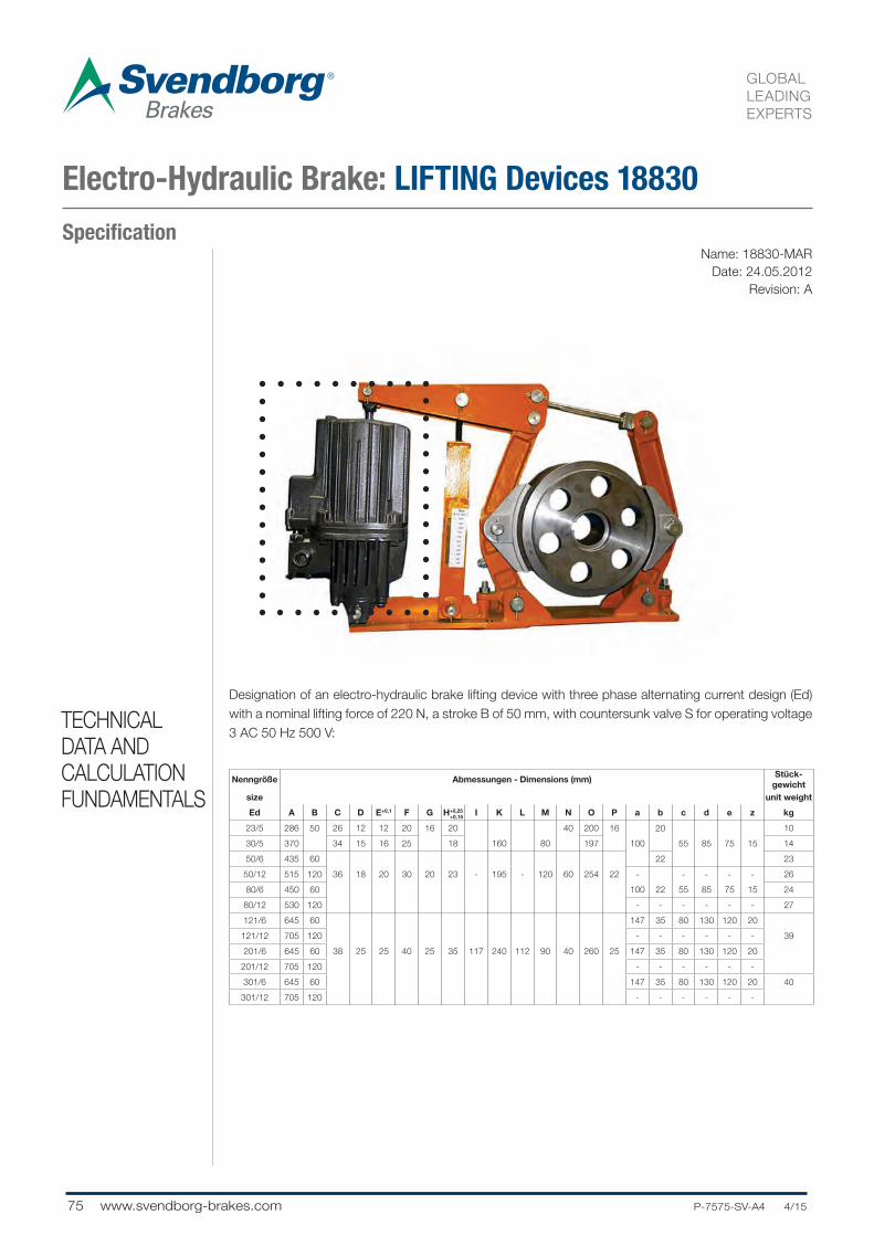
75 www.svendborg-brakes.com .....P-7575-SV-A4 4/15
GLOBAL
LEADING
EXPERTS
SpecificationName: 18830-MAR
Date: 24.05.2012
Revision: A
Electro-Hydraulic Brake: LIFTING Devices 18830
Designation of an electro-hydraulic brake lifting device with three phase alternating current design (Ed)
with a nominal lifting force of 220 N, a stroke B of 50 mm, with countersunk valve S for operating voltage
3 AC 50 Hz 500 V:TECHNICAL
DATA AND
CALCULATION
FUNDAMENTALSNenngröße Abmessungen - Dimensions (mm)
Stück-
gewicht
size unit weight
Ed A B C D E+0,1 F G H+0,25 I K L M N O P a b c d e z kg
23/5 286 50 26 12 12 20 16 20 40 200 16 20 10
30/5 370 34 15 16 25 18 160 80 197 100 55 85 75 15 14
50/6 435 60 22 23
50/12 515 120 36 18 20 30 20 23 - 195 - 120 60 254 22 - - - - - 26
80/6 450 60 100 22 55 85 75 15 24
80/12 530 120 - - - - - - 27
121/6 645 60 147 35 80 130 120 20
121/12 705 120 - - - - - - 39
201/6 645 60 38 25 25 40 25 35 117 240 112 90 40 260 25 147 35 80 130 120 20
201/12 705 120 - - - - - -
301/6 645 60 147 35 80 130 120 20 40
301/12 705 120 - - - - - -
+0,15

76P-7575-SV-A4 4/15.... www.svendborg-brakes.com
GLOBAL
LEADING
EXPERTS
SpecificationBrake lifting device Ed 23/5–S 50 Hz 500 V–NO 18830
L
K
BA
Ventilevalves
G
NM
F
DC
IH
P
O
E
z
ungespannt - not stressed(Gerät gelüftet - device lifted)
gespannt - stressed(Gerät im Bremszustand - device at braking)
c d
eF
E
bC
Aa
d - Federd - spring
Electro-Hydraulic Brake: LIFTING Devices 18830
DRAWINGS
CALCULATION
FUNDAMENTALS
Nenngröße Hubkraft Hubweg HubarbeitBremsfederkraft
(c - Feder)
Leistungs-
aufnahme
size stroke powerstroke
distance
stroke
operating
brake spring power
( c - spring)
power
input
Ed N mm N/cm N W
23/5 220 50 1100 180 165
30/5 300 1500 270 200
50/6 500 60 3000 460 210
50/12 120 6000 -
80/6 800 60 4800 750
80/12 120 9600 - 330
121/6 1250 60 7500 120
121/12 120 15000 -
201/6 2000 60 12000 1900 450
201/12 120 24000 -
301/6 3000 60 18000 2700 550
301/12 120 36000 -
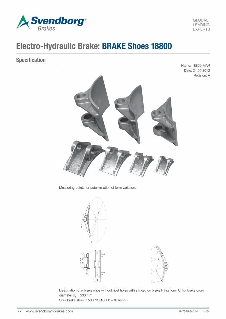
77 www.svendborg-brakes.com .....P-7575-SV-A4 4/15
GLOBAL
LEADING
EXPERTS
SpecificationName: 18800-MAR
Date: 24.05.2012
Revision: A
Electro-Hydraulic Brake: BRAKE Shoes 18800
Measuring points for determination of form variation.
Designation of a brake shoe without rivet holes with sticked on brake lining (form C) for brake drum
diameter d1 = 500 mm:
SB – brake shoe C 500 NO 18800 with lining 3)
m
c
e
b2
g1
f1 -
0,5
f2
+0
,5
g2
d1
d2
D1
0
Nenngrößesize
Nenngrößesize
70°
r

78P-7575-SV-A4 4/15.... www.svendborg-brakes.com
GLOBAL
LEADING
EXPERTS
Specification1) Admissible deviation of parallelism related to bores d2 and
sticking area.
2) Admissible form deviation related to friction area between
brake lining and brake drum (with tolerance range h11) reh11)
lated to measuring points n, o, p and n´, o´, p´.
3) SB – Brake lining according to NO 18812 respectively by
choice of purchaser.
Material: Aluminium – sand-casting
SB – Drum brakes see NO 18735
Electro-Hydraulic Brake: BRAKE Shoes 18800
CALCULATION
FUNDAMENTALS
Nenngröße Abmessungen - Dimensions (mm) Stückgewicht
sizezülassige 1)
Abweichung
zülassige
Formabw.unit weight
admissible admissible
deviation form deviation
d1
b2
c d2 / r e f
1f
2g
1g
2m
max.n-p, n´-p´ 2) kg
200 70 8 20 140 65 35 32 24 17 0,5
250 90 8 25 170 80 40 37 0,1 29 22 0,15 0,8
315 110 10 30 212 100 50 44,5 34,5 25 1,4
400 140 10 35 260 125 62 50 0,15 40 30 0,2 2,1
500 180 12 40 320 160 80 58 46 33 3,8
630 225 12 45 390 200 100 63 0,2 51 38 0,3 5,5
710 255 15 50 440 224 112 70 56 40 8,2

79 www.svendborg-brakes.com .....P-7575-SV-A4 4/15
GLOBAL
LEADING
EXPERTS
Notes:

HYDRAULIC WIND RANGESvendborg Brakes is the global market leader in intelligent braking solutions. This is why.
GLOBAL
LEADING
EXPERTS

81 www.svendborg-brakes.com .....P-7575-SV-A4 4/15
GLOBAL
LEADING
EXPERTS
Notes:

82P-7575-SV-A4 4/15.... www.svendborg-brakes.com
GLOBAL
LEADING
EXPERTS
Specification
Example for a Direct Drive Wind Turbine
Combined hydraulic power unit
for active rotor brake and rotor
lock control
Stand alone hydraulic power unit
for yaw brake control
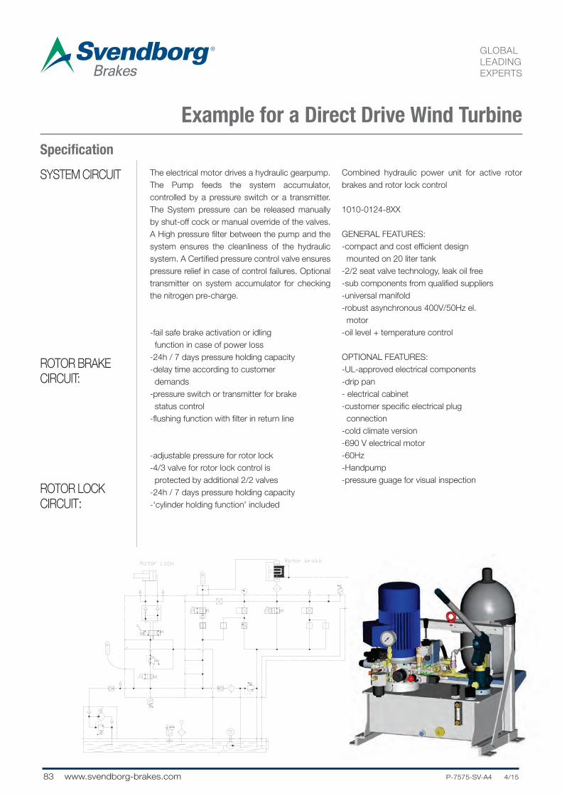
83 www.svendborg-brakes.com .....P-7575-SV-A4 4/15
GLOBAL
LEADING
EXPERTS
Specification
SYSTEM CIRCUIT
ROTOR BRAKE
CIRCUIT:
The electrical motor drives a hydraulic gearpump.
The Pump feeds the system accumulator,
controlled by a pressure switch or a transmitter.
The System pressure can be released manually
by shut-off cock or manual override of the valves.
A High pressure filter between the pump and the
system ensures the cleanliness of the hydraulic
system. A Certified pressure control valve ensures
pressure relief in case of control failures. Optional
transmitter on system accumulator for checking
the nitrogen pre-charge.
-fail safe brake activation or idling
function in case of power loss
-24h / 7 days pressure holding capacity
-delay time according to customer
demands
-pressure switch or transmitter for brake
status control
-flushing function with filter in return line
-adjustable pressure for rotor lock
-4/3 valve for rotor lock control is
protected by additional 2/2 valves
-24h / 7 days pressure holding capacity
-‘cylinder holding function’ included
Combined hydraulic power unit for active rotor
brakes and rotor lock control
1010-0124-8XX
GENERAL FEATURES:
-compact and cost efficient design
mounted on 20 liter tank
-2/2 seat valve technology, leak oil free
-sub components from qualified suppliers
-universal manifold
-robust asynchronous 400V/50Hz el.
motor
-oil level + temperature control
OPTIONAL FEATURES:
-UL-approved electrical components
-drip pan
- electrical cabinet
-customer specific electrical plug
connection
-cold climate version
-690 V electrical motor
-60Hz
-Handpump
-pressure guage for visual inspection
ROTOR LOCK
CIRCUIT:
Example for a Direct Drive Wind Turbine
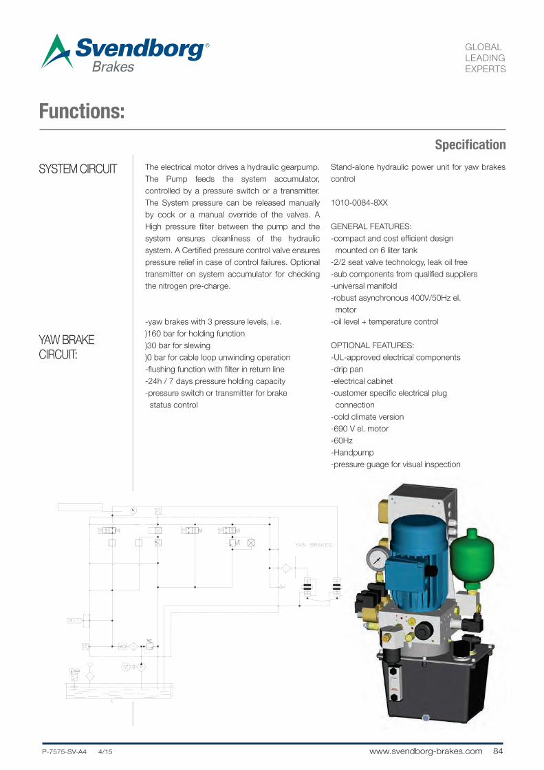
84P-7575-SV-A4 4/15.... www.svendborg-brakes.com
GLOBAL
LEADING
EXPERTS
Specification
SYSTEM CIRCUIT
YAW BRAKE
CIRCUIT:
Functions:
The electrical motor drives a hydraulic gearpump.
The Pump feeds the system accumulator,
controlled by a pressure switch or a transmitter.
The System pressure can be released manually
by cock or a manual override of the valves. A
High pressure filter between the pump and the
system ensures cleanliness of the hydraulic
system. A Certified pressure control valve ensures
pressure relief in case of control failures. Optional
transmitter on system accumulator for checking
the nitrogen pre-charge.
-yaw brakes with 3 pressure levels, i.e.
)160 bar for holding function
)30 bar for slewing
)0 bar for cable loop unwinding operation
-flushing function with filter in return line
-24h / 7 days pressure holding capacity
-pressure switch or transmitter for brake
status control
Stand-alone hydraulic power unit for yaw brakes
control
1010-0084-8XX
GENERAL FEATURES:
-compact and cost efficient design
mounted on 6 liter tank
-2/2 seat valve technology, leak oil free
-sub components from qualified suppliers
-universal manifold
-robust asynchronous 400V/50Hz el.
motor
-oil level + temperature control
OPTIONAL FEATURES:
-UL-approved electrical components
-drip pan
-electrical cabinet
-customer specific electrical plug
connection
-cold climate version
-690 V el. motor
-60Hz
-Handpump
-pressure guage for visual inspection

85 www.svendborg-brakes.com .....P-7575-SV-A4 4/15
GLOBAL
LEADING
EXPERTS
Specification
Example for a Direct Drive Wind Turbine
Combined hydraulic power unit
for active rotor brake and yaw
brake control
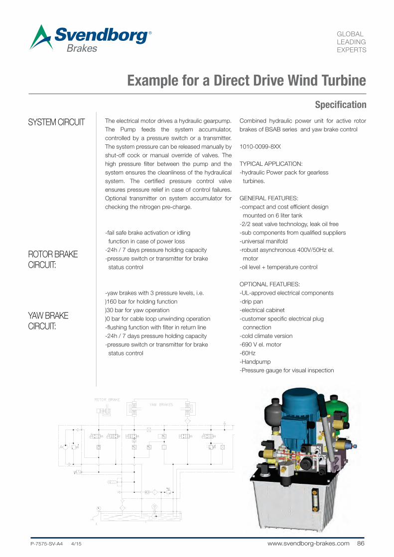
86P-7575-SV-A4 4/15.... www.svendborg-brakes.com
GLOBAL
LEADING
EXPERTS
Specification
SYSTEM CIRCUIT
ROTOR BRAKE
CIRCUIT:
YAW BRAKE
CIRCUIT:
The electrical motor drives a hydraulic gearpump.
The Pump feeds the system accumulator,
controlled by a pressure switch or a transmitter.
The system pressure can be released manually by
shut-off cock or manual override of valves. The
high pressure filter between the pump and the
system ensures the cleanliness of the hydraulical
system. The certified pressure control valve
ensures pressure relief in case of control failures.
Optional transmitter on system accumulator for
checking the nitrogen pre-charge.
-fail safe brake activation or idling
function in case of power loss
-24h / 7 days pressure holding capacity
-pressure switch or transmitter for brake
status control
-yaw brakes with 3 pressure levels, i.e.
)160 bar for holding function
)30 bar for yaw operation
)0 bar for cable loop unwinding operation
-flushing function with filter in return line
-24h / 7 days pressure holding capacity
-pressure switch or transmitter for brake
status control
Combined hydraulic power unit for active rotor
brakes of BSAB series and yaw brake control
1010-0099-8XX
TYPICAL APPLICATION:
-hydraulic Power pack for gearless
turbines.
GENERAL FEATURES:
-compact and cost efficient design
mounted on 6 liter tank
-2/2 seat valve technology, leak oil free
-sub components from qualified suppliers
-universal manifold
-robust asynchronous 400V/50Hz el.
motor
-oil level + temperature control
OPTIONAL FEATURES:
-UL-approved electrical components
-drip pan
-electrical cabinet
-customer specific electrical plug
connection
-cold climate version
-690 V el. motor
-60Hz
-Handpump
-Pressure gauge for visual inspection
Example for a Direct Drive Wind Turbine

87 www.svendborg-brakes.com .....P-7575-SV-A4 4/15
GLOBAL
LEADING
EXPERTS
Specification
Example for a Direct Drive Wind Turbine
Stand alone hydraulic power unit
for yaw brake control

88P-7575-SV-A4 4/15.... www.svendborg-brakes.com
GLOBAL
LEADING
EXPERTS
Specification
SYSTEM CIRCUIT
YAW BRAKE
CIRCUIT
The electrical motor drives a hydraulic gearpump.
The pump feeds the system accumulator,
controlled by a pressure switch or a transmitter.
The system pressure can be released manually by
a shut-off cock or by manual override of valves.
The high pressure filter between the pump and the
system ensures the cleanliness of the hydraulic
system. The certified pressure control valve
ensures pressure relief in case of control failures.
Optional transmitter on the system accumulator
for checking the nitrogen pre-charge.
-yaw brakes with 3 pressure levels, i.e.
)160 bar for holding function
)30 bar for yaw operation
)0 bar for cable loop unwinding operation
-flushing function with filter in return line
-24h / 7 days pressure holding capacity
-pressure switch or transmitter for brake
status control
Stand-alone hydraulic power unit for yaw brakes
control
1010-0084-8XX
GENERAL FEATURES:
-compact and cost efficient design
mounted on 6 liter tank
-2/2 seat valve technology, leak oil free
-sub components from qualified suppliers
-universal manifold
-robust asynchronous 400V/50Hz el.
motor
-oil level + temperature control
OPTIONAL FEATURES:
-UL-approved electrical components
-drip pan
-electrical cabinet
-customer specific electrical plug
connection
-cold climate version
-690 V el. motor
-60Hz
-Handpump
-pressure gauge for visual inspection
Example for a Direct Drive Wind Turbine
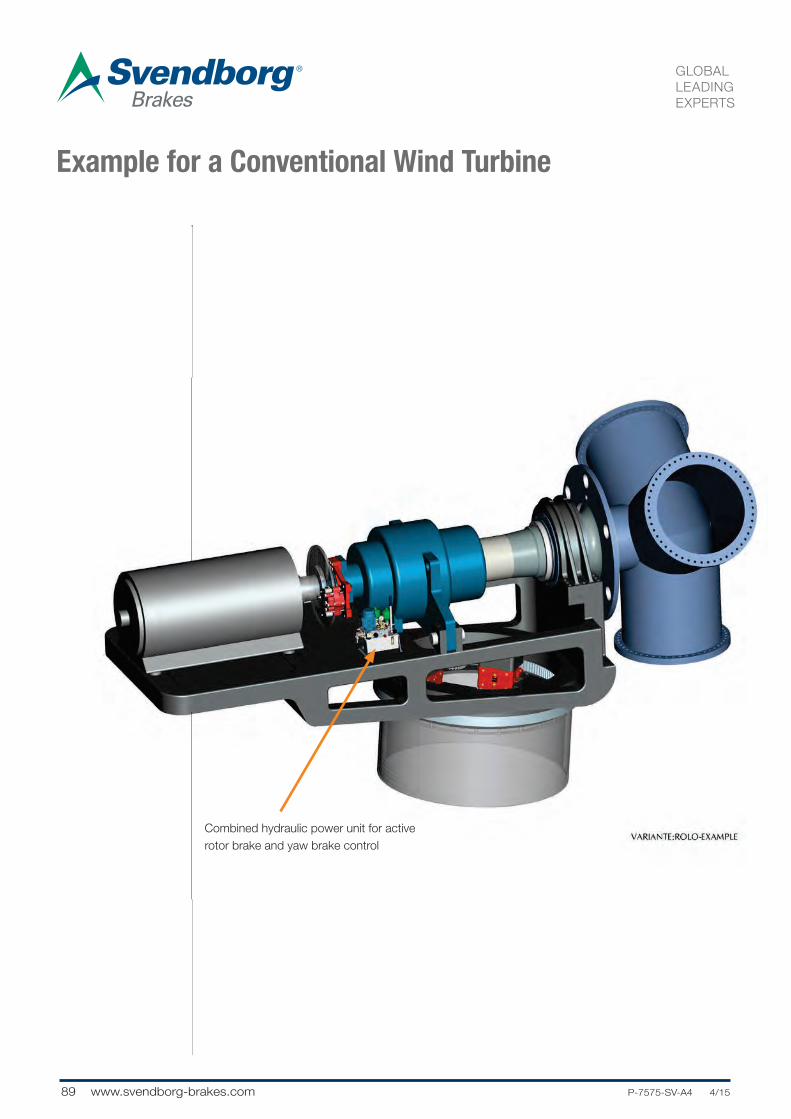
89 www.svendborg-brakes.com .....P-7575-SV-A4 4/15
GLOBAL
LEADING
EXPERTS
Example for a Conventional Wind Turbine
Combined hydraulic power unit for active
rotor brake and yaw brake control

90P-7575-SV-A4 4/15.... www.svendborg-brakes.com
GLOBAL
LEADING
EXPERTS
Specification
SYSTEM CIRCUIT
ROTOR BRAKE
CIRCUIT:
YAW BRAKE
CIRCUIT:
The electrical motor drives a hydraulic gearpump.
The pump feeds the system accumulator,
controlled by a pressure switch or a transmitter.
The system pressure can be released manually
by a shut-off cock or manual override of valves.
The high pressure filter between the pump and
the system ensures the cleanliness of hydraulic
system. The certified pressure control valve
ensures pressure relief in case of control failures.
Optional transmitter on system accumulator for
checking the nitrogen pre-charge.
-fail safe brake activation or idling
function in case of power loss
-24h / 7 days pressure holding capacity
-delay time according to customer
demands
-pressure switch or transmitter for brake
status control
-yaw brakes with 3 pressure levels, i.e.
)160 bar for holding function
)30 bar for yaw operation
)0 bar for cable loop unwinding operation
-flushing function with filter in return line
-24h / 7 days pressure holding capacity
-pressure switch or transmitter for brake
status control
Combined hydraulic power unit for active rotor
brakes and yaw brake control
1010-0139-8XX
GENERAL FEATURES:
-compact and cost efficient design
mounted on 10 liter tank
-2/2 seat valve technology, leak oil free
-sub components from qualified suppliers
-universal manifold
-robust asynchronous 400V/50Hz el.
motor
-oil level + temperature control
OPTIONAL FEATURES:
-UL approved electrical components
-drip pan
-electrical cabinet
-customer specific electrical plug
connection
-cold climate version
-690 V el. motor
-60Hz
-Handpump
-Pressure gauge for visual inspection
Example for a Conventional Wind Turbine

91 www.svendborg-brakes.com .....P-7575-SV-A4 4/15
GLOBAL
LEADING
EXPERTS
Notes:

92P-7575-SV-A4 4/15.... www.svendborg-brakes.com
GLOBAL
LEADING
EXPERTS
Specification
Example for a Conventional Wind Turbine
Combined hydraulic power unit for
yaw brake and rotor lock control
Stand alone hydraulic power unit
for active rotor brake control

93 www.svendborg-brakes.com .....P-7575-SV-A4 4/15
GLOBAL
LEADING
EXPERTS
Specification
SYSTEM CIRCUIT
ROTOR LOCK
CIRCUIT:
YAW BRAKE
CIRCUIT:
The electrical motor drives a hydraulic gearpump.
The pump feeds the system accumulator,
controlled by a pressure switch or a transmitter.
The system pressure can be released manually by
a shut-off cock or manual override of valves. The
high pressure filter between the pump and the
system ensures cleanliness of hydraulic system.
The certified pressure control valve ensures
pressure relief in case of control failures. Optional
transmitter on system accumulator for checking
the nitrogen pre-charge.
-adjustable pressure for rotor lock
-4/3 valve for rotor lock control is
protected by additional 2/2 valves
-24h / 7 days pressure holding capacity
-‘cylinder holding function’ included
-yaw brakes with 3 pressure levels, i.e.
)160 bar for holding function
)30 bar for yaw operation
)0 bar for cable loop unwinding operation
-flushing function with filter in return line
-24h / 7 days pressure holding capacity
-pressure switch or transmitter for brake
status control
Combined hydraulic power unit for yaw brake
and rotor lock control
1010-0124-802
GENERAL FEATURES:
-compact and cost efficient design
mounted on 6 liter tank
-2/2 seat valve technology, leak oil free
-sub components from qualified suppliers
-universal manifold
-robust asynchronous 400V/50Hz el.
motor
-oil level + temperature control
OPTIONAL FEATURES:
-UL-approved electrical components
-drip pan
-electrical cabinet
-customer specific electrical plug
connection
-cold climate version
-690 V el. motor
-60Hz
-handpump
-pressure gauge for visual inspection
Example for a Conventional Wind Turbine

94P-7575-SV-A4 4/15.... www.svendborg-brakes.com
GLOBAL
LEADING
EXPERTS
Specification
SYSTEM CIRCUIT
ROTOR BRAKE
CIRCUIT
The electrical motor drives a hydraulic gearpump.
The pump feeds the system accumulator,
controlled by a pressure switch or a transmitter.
The system pressure can be released manually by
shut-off cock or manual override of valves. The
high pressure filter between the pump and the
system ensures the cleanliness of the hydraulic
system. The certified pressure control valve
ensures pressure relief in case of control failures.
Optional transmitter on system accumulator for
checking the nitrogen pre-charge.
-fail safe brake activation or idling
function in case of power loss
-2 modes of brake activation, with and
without delay
-2 step braking torque, i.e. reduced torque
for braking, full torque for holding
function
-24h / 7 days pressure holding capacity
-delay time according to customer
demands
-pressure switch or transmitter for brake
status control
Stand-alone hydraulic power unit for active rotor
brakes (on hss)
1010-006X-8XX
GENERAL FEATURES:
-compact and cost efficient design
mounted on 3 liter tank
-2/2 seat valve technology, leak oil free
-sub components from qualified suppliers
-universal manifold
-robust asynchronous 400V/50Hz el.
motor
-oil level + temperature control
OPTIONAL FEATURES:
-UL-approved electrical components
-drip pan
-electrical cabinet
-customer specific electrical plug
connection
-cold climate version
-690 V el. motor
-60Hz
-Handpump
-pressure gauge for visual
inspection
Example for a Conventional Wind Turbine
Specification

95 www.svendborg-brakes.com .....P-7575-SV-A4 4/15
GLOBAL
LEADING
EXPERTS
Notes:

96P-7575-SV-A4 4/15.... www.svendborg-brakes.com
GLOBAL
LEADING
EXPERTS
Specification
Example for a Compact Drive Wind Turbine
Combined hydraulic power unit
for rotor lock and roof hatch
control
Combined hydraulic power unit
for yaw brake and rotor brake
control

97 www.svendborg-brakes.com .....P-7575-SV-A4 4/15
GLOBAL
LEADING
EXPERTS
Specification
SYSTEM CIRCUIT
ROTOR LOCK
CIRCUIT:
The electical motor drives a hydraulic gearpump.
The pump feeds the system accumulator, con-
trolled by a pressure switch or a transmitter. The
system pressure can be released manually by a
shut-off cock or by manual override of valves. The
high pressure filter between the pump and the sy-
stem ensures the cleanliness of the hydraulic sy-
stem. The certified pressure control valve ensures
pressure relief in case of control failures.
-adjustable pressure for rotor lock
-4/3 valve for rotor lock control is
protected by additional 2/2 valves
-24h / 7 days pressure holding capacity
-‘cylinder holding function’ included
-over pressure protection with pressure
relief valves
-manual activation of the valve or via
remote control
-‘Auto-Rolo’ capable
-hyd. cylinder for hatches can be operated
separately
-adjustable pressure
-manual activation of the valves or via
remote control
Combined hydraulic power unit for activating
rotor locks and roof hatch control
1110-0002-8XX
TYPICAL APPLICATION:
-Service hydraulic for multi-megawatt
turbines
GENERAL FEATURES:
-compact and cost efficient design
mounted on 25 liter tank
-sub components from qualified suppliers
-universal manifold
-robust asynchronous 400V/50Hz el.
motor
-oil level + temperature control
OPTIONAL FEATURES:
-UL-approved electrical components
-drip pan
-electrical cabinet
-remote control operating panel
-customer specific electrical plugconnection
-cold climate version
-690 V el. motor
-60Hz
-Handpump
-pressure gauge for visual inspection
ROOF HATCHES
CIRCUIT:
Example for a Compact Drive Wind Turbine

98P-7575-SV-A4 4/15.... www.svendborg-brakes.com
GLOBAL
LEADING
EXPERTS
Specification
SYSTEM CIRCUIT
ROTOR BRAKE
CIRCUIT:
The electrical motor drives a hydraulic gearpump.
The Pump feeds the system accumulator, con-
trolled by a pressure switch or a transmitter. The
system pressure can be released manually by
shut-off cock or manual override of valves. The
high pressure filter between the pump and the sy-
stem ensures the cleanliness of the hydraulical sy-
stem. The certified pressure control valve ensures
pressure relief in case of control failures. Optional
transmitter on system accumulator for checking
the nitrogen pre-charge.
-fail safe brake activation or idling
function in case of power loss
-24h / 7 days pressure holding capacity
-pressure switch or transmitter for brake
status control
-yaw brakes with 3 pressure levels, i.e.
)160 bar for holding function
)30 bar for yaw operation
)0 bar for cable loop unwinding operation
-flushing function with filter in return line
-24h / 7 days pressure holding capacity
-pressure switch or transmitter for brake
status control
Combined hydraulic power unit for active rotor
brakes of BSAB series and yaw brake control
1010-0099-8XX
GENERAL FEATURES:
-compact and cost efficient design
mounted on 6 liter tank
-2/2 seat valve technology, leak oil free
-sub components from qualified suppliers
-universe manifold
-robust asynchronous 400V/50Hz el.
motor
-oil level + temperature control
OPTIONAL FEATURES:
-UL-approved electrical components
-drip pan
-electrical cabinet
-customer specific electrical plug
connection
-cold climate version
-690 V el. motor
-60Hz
-Handpump
-Pressure gauge for visual inspection
YAW BRAKE
CIRCUIT:
Example for a Compact Drive Wind Turbine

99 www.svendborg-brakes.com .....P-7575-SV-A4 4/15
GLOBAL
LEADING
EXPERTS
Notes:

100P-7575-SV-A4 4/15.... www.svendborg-brakes.com
GLOBAL
LEADING
EXPERTS
Specification
Example for a Compact Drive Wind Turbine
Stand alone hydraulic power unit
for active rotor lock control
Combined hydraulic power unit
for yaw brake and rotor brake
control

101 www.svendborg-brakes.com .....P-7575-SV-A4 4/15
GLOBAL
LEADING
EXPERTS
Specification
SYSTEM CIRCUIT
ROTOR BRAKE
CIRCUIT:
YAW BRAKE
CIRCUIT:
Example for a Compact Drive Wind Turbine
The electrical motor drives a hydraulic gearpump.
The Pump feeds the system accumulator,
controlled by a pressure switch or a transmitter.
The system pressure can be released manually by
shut-off cock or manual override of valves. The
high pressure filter between the pump and the
system ensures the cleanliness of the hydraulical
system. The certified pressure control valve
ensures pressure relief in case of control failures.
Optional transmitter on system accumulator for
checking the nitrogen pre-charge.
-fail safe brake activation or idling
function in case of power loss
-24h / 7 days pressure holding capacity
-pressure switch or transmitter for brake
status control
-yaw brakes with 3 pressure levels, i.e.
)160 bar for holding function
)30 bar for yaw operation
)0 bar for cable loop unwinding operation
-flushing function with filter in return line
-24h / 7 days pressure holding capacity
-pressure switch or transmitter for brake
status control
Combined hydraulic power unit for active rotor
brakes of BSAB series and yaw brake control
1010-0099-8XX
GENERAL FEATURES:
-compact and cost efficient design
mounted on 6 liter tank
-2/2 seat valve technology, leak oil free
-sub components from qualified suppliers
-universal manifold
-robust asynchronous 400V/50Hz el.
motor
-oil level + temperature control
OPTIONAL FEATURES:
-UL-approved electrical components
-drip pan
-electrical cabinet
-customer specific electrical plug
connection
-cold climate version
-690 V el. motor
-60Hz
-Handpump
-Pressure gauge for visual inspection
connection
-cold climate version
-690 V el. motor
-60Hz
-Handpump
-pressure gauge
for visual inspection

102P-7575-SV-A4 4/15.... www.svendborg-brakes.com
GLOBAL
LEADING
EXPERTS
Specification
SYSTEM CIRCUIT
ROTOR LOCK
CIRCUIT:
The electrical motor drives a hydraulic. gearpump.
The pump feeds the system accumulator,
controlled by a pressure switch or a transmitter.
The system pressure can be released manually by
a shut-off cock or by manual override of valves.
The high pressure filter between the pump and the
system ensures the cleanliness of the hydraulic
system. The certified pressure control valve
ensures pressure relief in case of control failures.
-control valve is protected by additional
2/2 valve
-24h / 7 days pressure holding capacity
-‘cylinder holding function’ included
-manual activation of the valve or via
remote control
Stand-alone hydraulic power unit for rotor lock
control
1110-0012-8XX
TYPICAL APPLICATION:
-Service hydraulic for multi-megawatt
turbines
GENERAL FEATURES:
-compact and cost efficient design
mounted on 20 liter tank
-sub components from qualified suppliers
-universal manifold
-robust asynchronous 400V/50Hz el.
motor
-oil level + temperature control
OPTIONAL FEATURES:
-UL-approved electrical components
-drip pan
-electrical cabinet
-remote control operating panel
-customer specific electrical plug
connection
-cold climate version
-690 V el. motor
-60Hz
-Handpump
-pressure gauge for visual inspection
Example for a Compact Drive Wind Turbine

103 www.svendborg-brakes.com .....P-7575-SV-A4 4/15
GLOBAL
LEADING
EXPERTS
Notes:

104P-7575-SV-A4 4/15.... www.svendborg-brakes.com
GLOBAL
LEADING
EXPERTS
Specification
Example for a Compact Drive Wind Turbine
Combined hydraulic power unit
for active rotor lock
and rotor brake control
Stand alone hydraulic power unit
for yaw brake control

105 www.svendborg-brakes.com .....P-7575-SV-A4 4/15
GLOBAL
LEADING
EXPERTS
Specification
SYSTEM CIRCUIT
YAW BRAKE
CIRCUIT:
The electrical motor drives a hydraulic gearpump.
The pump feeds the system accumulator,
controlled by a pressure switch or a transmitter.
The system pressure can be released manually by
a shut-off cock or by manual override of valves.
The high pressure filter between the pump and the
system ensures the cleanliness of the hydraulic
system. The certified pressure control valve
ensures pressure relief in case of control failures.
Optional transmitter on the system accumulator
for checking the nitrogen pre-charge.
-yaw brakes with 3 pressure levels, i.e.
)160 bar for holding function
)30 bar for yaw operation
)0 bar for cable loop unwinding operation
-flushing function with filter in return line
-24h / 7 days pressure holding capacity
-pressure switch or transmitter for brake
status control
Stand-alone hydraulic power unit for yaw brakes
control
1010-0084-8XX
GENERAL FEATURES:
-compact and cost efficient design
mounted on 6 liter tank
-2/2 seat valve technology, leak oil free
-sub components from qualified suppliers
-universal manifold
-robust asynchronous 400V/50Hz el.
motor
-oil level + temperature control
OPTIONAL FEATURES:
-UL-approved electrical components
-drip pan
-electrical cabinet
-customer specific electrical plug
connection
-cold climate version
-690 V el. motor
-60Hz
-Handpump
-pressure gauge for visual inspection
Example for a Compact Drive Wind Turbine
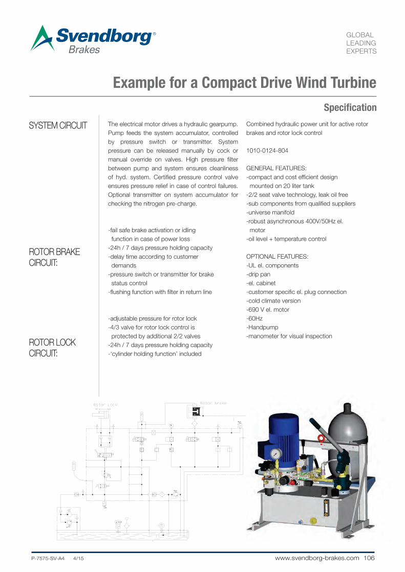
106P-7575-SV-A4 4/15.... www.svendborg-brakes.com
GLOBAL
LEADING
EXPERTS
Specification
SYSTEM CIRCUIT
ROTOR BRAKE
CIRCUIT:
The electrical motor drives a hydraulic gearpump.
Pump feeds the system accumulator, controlled
by pressure switch or transmitter. System
pressure can be released manually by cock or
manual override on valves. High pressure filter
between pump and system ensures cleanliness
of hyd. system. Certified pressure control valve
ensures pressure relief in case of control failures.
Optional transmitter on system accumulator for
checking the nitrogen pre-charge.
-fail safe brake activation or idling
function in case of power loss
-24h / 7 days pressure holding capacity
-delay time according to customer
demands
-pressure switch or transmitter for brake
status control
-flushing function with filter in return line
-adjustable pressure for rotor lock
-4/3 valve for rotor lock control is
protected by additional 2/2 valves
-24h / 7 days pressure holding capacity
-‘cylinder holding function’ included
Combined hydraulic power unit for active rotor
brakes and rotor lock control
1010-0124-804
GENERAL FEATURES:
-compact and cost efficient design
mounted on 20 liter tank
-2/2 seat valve technology, leak oil free
-sub components from qualified suppliers
-universe manifold
-robust asynchronous 400V/50Hz el.
motor
-oil level + temperature control
OPTIONAL FEATURES:
-UL el. components
-drip pan
-el. cabinet
-customer specific el. plug connection
-cold climate version
-690 V el. motor
-60Hz
-Handpump
-manometer for visual inspection
ROTOR LOCK
CIRCUIT:
Example for a Compact Drive Wind Turbine

107 www.svendborg-brakes.com .....P-7575-SV-A4 4/15
GLOBAL
LEADING
EXPERTS
Notes:

108P-7575-SV-A4 4/15.... www.svendborg-brakes.com
GLOBAL
LEADING
EXPERTS
Notes:

109 www.svendborg-brakes.com .....P-7575-SV-A4 4/15
GLOBAL
LEADING
EXPERTS
Notes:

Other product solutions fromAltra Industrial MotionOur comprehensive product offering is comprised of nine major
categories including electromagnetic clutches and brakes, heavy duty
clutches and brakes, overrunning clutches, gearing, engineered and
precision couplings, engineered bearing assemblies, linear products,
belted drives and air motors. With thousands of product solutions
available, Altra provides true single source convenience while meeting
specific customer requirements. Many major OEM’s and end users prefer
Altra products as their No.1 choice for performance and reliability.
Linear Products
Warner Linear
Engineered Bearing Assemblies
Kilian Manufacturing
Precision Couplings and Air Motors
Huco Dynatork
Belted Drives and Sheaves
TB Wood’s
Heavy Duty Clutches and Brakes
Wichita ClutchTwiflex LimitedIndustrial ClutchSvendborg Brakes
Electromagnetic Clutches and Brakes
Warner ElectricInertia DynamicsMatrix International
Overrunning Clutches
Formsprag ClutchMarland ClutchStieber Clutch
Engineered Couplings and Universal Joints
TB Wood’sAmeridrives CouplingsAmeridrives Power TransmissionBibby Turboflex Lamiflex CouplingsGuardian Couplings
Gearing
Boston GearNuttall GearDelroyd Worm GearBauer Gear Motor
The power of one, the strength of many.
www.altramotion.com