Embed Size (px)
Citation preview

Magnet protection studies and heater design
Susana Izquierdo Bermudez
2Susana Izquierdo Bermudez
OUTLINE1 Margin and MIITs overview
2 Quench study based on FNAL 11T tests results1 Longitudinal quench propagation
2 Heaters delay
3 Quench Integral (QI)
4 Time budget
3 Minimize heaters delay1 Inter-layer heaters
2 Reduce kapton thickness from heater to coil
3 Quench heater design optimization
4 Quench performance under accelerator conditions
5 Additional remarks
6 Baseline design
7 ConclusionsFuture actions
3Susana Izquierdo Bermudez
1 Margin and MIITs overview
11 T 1122 T central field
145 K
5 K
Temperature Margin T(MIITs) 11T cable
Parameter MB 11T
MIITs to reach 400 K 8T MA2s 52 18
Temperature margin LF 4 8-9
Temperature margin HF 3-4 5-9
Differential Inductance mHm 69 117
Stored energy kJm 567 897
4Susana Izquierdo Bermudez
Longitudinal quench propagation2D+1 thermal network Study the propagation of an initial resistive zone of 3 cm length in different turnsI = 11850 A Tbath=19KElement size in the longitudinal direction = 1 mmAdaptive time stepping (min = 10-7s max = 10-5s]
2 3 4 5 6 7 8 9 10 11 120
5
10
15
20
25
30
35ROXIE
Experimental
Average field in the conductor (T)lo
ng
itu
din
al p
rop
ag
ati
on
ve
-lo
cit
y (
ms
)
Pole turn IL (high field) v asymp 30 msMid-plane turn OL (low field) v asymp 65 ms
The longitudinal quench propagation velocity in MBHSP01 was measured in one of the quenches in the inner-layer pole turn at 45 K using the time-of-flight method as ~27 ms at 73 of SSL at 45 K
2Quench study based on FNAL 11T tests longitudinal quench propagation
Block 572 ms
Block 6134 ms
Experimental data courtesy of Guram Chlachidze
5Susana Izquierdo Bermudez
Insulation heater2coil = 114 microm kapton + 125 microm G10
Insulation heater2bath = 508 microm kapton
2Quench study based on FNAL 11T tests Quench Heaters Delay
40 45 50 55 60 65 70 75 800
10
20
30
40
50
60
70
80
90
measured MBSHP02 roxie MBSHP02measured MBSHP01 roxie MBSHP01
IIss ()
PH
de
lay
(m
s)
HFU voltage of 400 V ~ 65 Wcm2 peak power density
MBSHP02 Po LF = 65 Wcm2 Po HF=39 Wcm2 =31 ms
Experimental data courtesy of Guram ChlachidzeROXIE quench heater model
heater
Tuning factor (k) on GijTheater2coilbath to fit
experimental and computed heater delays
k=042
6Susana Izquierdo Bermudez
2Quench study based on FNAL 11T tests QI study
I0 = 11850 A Tbath = 19 K
MIITs after heater effective [MA2s]
MIITs from heater fired until effective [MA2s]
OL-IL delay[ms]
PH delay[ms]
Experimental data 108 37 134 asymp27CASE1 OL heaters fired t=0(computed heat transfer from heater to coil) 123 29 425 21
CASE2 OL quenched PH measured delay(OL fully quenched at PH measured delay) 114 38 338 27
Max Temperature [K]
Heaters fired t=0
OL quenched measured delay
Manual trips with the two operating protection heatersDump delay 1000 ms Self-dump
Experimental data courtesy of Guram Chlachidze
7Susana Izquierdo Bermudez
Manual trips with the two operating protection heatersDump delay 1000 ms Self-dump
2Quench study based on FNAL 11T tests QI study
Remark MATPRO database material properties MIITs 6 lower for CUDICryocomp database (mainly due to Copper Thermal Conductivity)
httpsespacecernchroxieDocumentationMaterialspdf
084 MIITs difference
Additional time budget 6 ms
Experimental data courtesy of Guram Chlachidze
QI after heaters effective
8Susana Izquierdo Bermudez
2Quench study based on FNAL 11T tests Time budget
120591119887119906119889119892119890119905=119876119868119898119886119909minus119876119868119889119890119888119886119910
119868 02
QImax = 18 MA2s
QIdecay = 108 MA2s
I0 = 11850 A
(experimental)
120591119887119906119889119892119890119905=51119898119904
Detection timebull Time to get over the threshold 3-6 msbull Validation time 10 ms
Heating firing delay 5 ms Heater delay (experimental) 27 ms
Time needed to quench45-48 ms
Non-redundant (all quench heaters fired)
Redundant (half of the quench heaters fired)
QIdecay = 116 MA2s(experimental)
120591119887119906119889119892119890119905=46119898119904
We are tight We need to minimize heaters delay
actual value in RB circuits 30 ms
9Susana Izquierdo Bermudez
3 Minimize heaters delay inter-layer heaters
Parameter Case 1
(only OL)Case 6(OL+IL)
OL HF heater delay ms 146 101OL LF heater delay ms 277 195
IL delay ms 565 70MIITs total MA2s 182 152
MIITs after heater effective MA2s 136 117MIITs heater fired until effective MA2s 21 10
Peak temperature in coil K 440 322Peak temperature in heater K 292 260
Δ OL HF QHdelay = - 31 Δ IL Qhdelay = - 88 ΔTmax = - 27
RemarksThermal contact resistances (eg between insulation layers) not included the same scaling factor as the one used to fit the FNAL test data is kept for this simulationThe insulation is a combination of glass fiber and Mica At the moment in the model we use G10
CASE 1 Only Outer Layer Heaters
Heater parameters
bull Insulation heater2coil = 114 microm kapton + 125 microm G10 + conductor insulation
bull Insulation heater2bath = 508 microm kaptonbull Po = 70 Wcm2 =74 ms ΔtQHdelay=5 msbull Non-redundant configuration
Some technical development required before inter-layer heaters become a feasible option
CASE 2 Outer Layer + Inter Layer Heaters
10Susana Izquierdo Bermudez
3 Minimize heaters delay reduce kapton thickness
Parameter Case 1114microm k
Case 250microm k
OL HF heater delay ms 21 14OL LF heater delay ms 335 24
IL delay ms 71 63MIITs total MA2s 176 163
MIITs after heater effective MA2s 122 12MIITs heater fired until effective MA2s 46 4
Peak temperature in coil K 422 367Peak temperature in heater K 208 196
Δ OL HF QHdelay = - 33 ΔTmax = - 13
CASE 1Insulation heater2coil = 114 microm kapton + 125 microm G10 + conductor insulationInsulation heater2bath = 508 microm kaptonCASE 2Insulation heater2coil = 50 microm kapton + 125 microm G10 + conductor insulationInsulation heater2bath = 508 microm kapton
Po = 64 Wcm2 (LF) 39 Wcm2 (HF) =31 ms ΔtQHdelay =5ms Non-redundant configurationQuench validation 100mV 10ms
11Susana Izquierdo Bermudez
3 Minimize heaters delay heater design optimization
DESIGN GUIDELINESbull Heaters should cover as many turns as possiblebull Design should be suitable for a 55 m length magnet heating stationsbull Aiming to heater delays lt 20 ms bull Two independent circuits (for redundancy)bull Higher power density in the LF region
Circuit 1Circuit 2
12Susana Izquierdo Bermudez
3 Minimize heaters delay heater design optimization
For long magnets the total heater resistance becomes too high Heating stations2 possible options
Heating stations LARPLQ example wide section = 23 mm narrow section 9 mm
distance between stations 100mm
LHC copper plated solutionMB example 15 mm width 400 mm plated 120 mm un-plated
Qualitative tests at CERN to understand how smooth the transition between narrow and wide section should be in order to avoid high spot temperaturesMore development required to find a solution which combines smooth transition enough coverage and distance in between heater stations small enough to allow fast quench propagation in the longitudinal direction
BASELINE SOLUTION FOR THE FIRST MODEL = COPPER PLATED SOLUTION Thanks to Vladimir Datskov amp Glyn Kirby
13Susana Izquierdo Bermudez
50 60 70 80 90 100 110 120 130 140 15000
200
400
600
800
1000
1200
1400
Low Field Region High Field Region
Heater Current (A)
Po
wer
den
sity
(W
cm
2)
Operation area
3 Minimize heaters delay heater design optimization
bull Width -gt Cover as many turns as possible
bull LF 20 mm bull HF 24 mm
bull Power densitybull LF asymp 75 Wcm2
bull HFasymp 55 Wcm2
Even if the operational current is expected to be in the range 100-120 A it would be good to have the possibility to go up to 150 A during short model tests to check the saturation of the system in terms of heater delays
119875119889=1198682119877119908119871
119877=120588 119871119908119905
119875119889=1198682 1205881199082119905
Heater width20 mm LF 24 mm HFρss=7810-7Ωm RRR=134
bull Distance between heater stations -gt quench propagation in between stations asymp 5 msbull LF 90 mmbull HF 130 mm
bull Coverage maximum coverage keeping the resistance within the allowable limits for a 55m magnet (depends on the number of power suppliesheater circuits)
Coverage Distance between stations
wid
th
14Susana Izquierdo Bermudez
OBJECTIVE Stay within LHC standard quench heater supply limits
(V = 450 V C=705 mF Ip asymp 85 A but it can safely operate up to 300 A)
V (V)
I (A)
C (mF)
Tau(ms)
Max Energy (kJ)
Power density(Wcm2)
900 120
705 55
28 84 (LF)58 (HF)
850 113 25 75 (LF)52 (HF)
For a 55 m magnet and 50 mm coverage
During first short model test Higher currents (up to 150) to check the saturation of the system in terms of heater delay
3 Minimize heaters delay heater design optimization
15Susana Izquierdo Bermudez
3 Minimize heaters delay heater design optimization
Baseline solution
+-+-
-
+
-
+-
-+
+
50 90130
202
4
Heater strip Heater circuit
If heater delays becomes too high andor current decay too slowhellipwe still can
Duplicate the heater coverage (50mm100mm) + parallel circuit
Duplicate the heater coverage (50mm100mm) + independent circuits
We need 2 times more current from the power supply
We duplicate the number of power supplies
16Susana Izquierdo Bermudez
3D simulation with heater stations
1 MIITs difference
Time budget 7 ms higher in case of full coverage
Full coverage vs heating stations
3 Minimize heaters delay heater design optimization
50 90130
202
4
Remark ROXIE does not have adaptive mesh tracking (which is a must for practical quench simulation)
17Susana Izquierdo Bermudez
4 Quench performance under accelerator conditions (I)
bull Quench initiation and protectionbull INZ in the pole turn inner layer (high field) 3 cm length bull Quench detection at 100 mV (time required to reach this threshold from quench initiation = 3 ms) 1
bull Validation time = 10 msbull Quench heaters (only outer layer heaters)
bull Heater-firing delay = 5 ms (time from firing the heaters to heaters effective)bull Po = 84 Wcm2 (LF) 58 Wcm2 (HF) tau = 55 ms
bull Insulation heater2coil = 50 microm kapton + 125 microm G10 Insulation heater2bath = 508 microm kaptonbull Redundant configuration (only half of the heaters fired)
bull Cable eddy-currents are considered using Rc = 30 μΩ for the cross-over resistance in a cored cable and 03 μΩ for Ra
bull Electrical network
1 The results presented later on correspond to a 2D simulation (X-Sec) 2D+1 thermal network is used only for the computation of the longitudinal propagation velocity Simulation yields to v = 30 ms in the pole turn and 3 ms are needed to reach 100 mV for an INZ of 3 cm length
Rdu
mp =
15
mΩ
Cold diode
Uthr=6V Rdiff=01 microΩ
L = 159 HQuenching magnet
18Susana Izquierdo Bermudez
Que
nch
initi
atio
n
Que
nch
dete
ctio
n
Val
idat
ion
and
po
wer
su
pply
off
Que
nch
hea
ter
effe
ctiv
e
Que
nch
hea
ter
prov
oked
qu
enc
h
t=0 t=3 ms t=13 ms t=18 ms t=31 ms
25 MA2sMIITs 18 MA2s 131 MA2s
4 Quench performance under accelerator conditions (II)
450
0
TOTAL MIITs = 174 MA2s
19Susana Izquierdo Bermudez
5 Final Remarksbull The model is a mix of optimistic and pessimistic assumptions
bull PESSIMISTICbull There is no cooling in the coil except through the heaters once the heater temperature
is lower than the coil temperature
bull OPTIMISTICbull The detection threshold is 01 V with 10 ms validation delaybull Delay between quench detection and heater firing is 5 ms (actual value in LHC RB
circuits up to 50 ms)
bull ROXIE thermal network has limitations that we try to overcome via fitting factorsbull More detailed quench heaters model show better agreement with experimental
results without any free parameters [Tiina Salmi]bull Inter-layer quench propagation computed in ROXIE is much slower than
experimental resultsbull Adaptive mesh tracking is a must for efficient quench simulation [Luca Bottura
MT23]
bull CERN uses mica-glass insulation (lower thermal conductivity than G10)bull REF Thermal Conductivity of Micaglass Insulation for Impregnated Nb3Sn
Windings in Accelerator Magnets Andries den Ouden and Herman HJ ten Kate
20Susana Izquierdo Bermudez
6 Baseline designbull Only outer layer heaters not potted with the coilbull Copper cladded heating stations 50 mm coverage 90 mm in between
heater stations for the low field region and 130 mm for the high fieldbull Heater to coil insulation = 50 microm kapton + 125 microm G10 bull Voltage tap location
x x x
x x x
x x xx x x
x
x
xNb3Sn-NbTi
x x x
x x x
x x xx x x
xx
x
xxx
xLayer jump
xNb3Sn-NbTi
Outer Layer Inner Layer
(full monitoring of the mid-plane and pole turns)
21Susana Izquierdo Bermudez
7 ConclusionsFuture workbull The low CuSC ratio combined with the larger temperature margins
make the protection of the 11T dipole a non-trivial problembull Efficient heat transfer from quench heaters to coil is a must
bull Minimize insulation thickness assuring electrical integritybull High power density and coverage require high currents andor big
number of heating firing unitsbull Efficient configuration in terms of heating stations
bull Inter-layer heaters are an interesting bull Lower margin in the inner layer faster heater provoked quenchbull More uniform heat propagation within the coilbull Simplify the requirement of having a redundant system
bull Could AC losses trigger a quench (discharge of capacitance) How would it impact the rest of the RB circuit
bull Quench-back modeling needs to be improved
22Susana Izquierdo Bermudez
Referencesbull Quench heater experiments on the lhc main superconducting magnets F Rodriguez-Mateos P
PugnatS Sanfilippo R Schmidt A Siemko F Sonnemannbull LQ Protection Heater Test at Liquid Nitrogen Temperature G Chlachidze G Ambrosio H Felice1 F
Lewis FNobrega D Orris TD-09-007bull Experimental Results and Analysis from the 11T Nb3Sn DS Dipole G Chlachidze I Novitski AV
Zlobin (Fermilab) B Auchmann M Karppinen (CERN)bull EDMS1257407 11-T protection studies at CERN B Auchmannbull Challenges in the Thermal Modeling of Quenches with ROXIE Nikolai Schwerg Bernhard
Auchmann and Stephan Russenschuckbull Quench Simulation in an Integrated Design Environment for Superconducting Magnets Nikolai
Schwerg Bernhard Auchmann and Stephan Russenschuckbull Numerical Calculation of Transient Field Effects in Quenching Superconducting Magnets PhD
Thesis Juljan Nikolai Schwergbull Thermal Conductivity of Micaglass Insulation for Impregnated Nb3Sn Windings in Accelerator
Magnets Andries den Ouden and Herman HJ ten Katebull Electrodynamics of superconducting cables in accelerator magnets Arjan Peter Verweijbull Rossi L et al MATPRO a computer library of material property at cryogenic temperature Tech
Report INFN 2006bull httpte-epc-lpcwebcernchte-epc-lpcconvertersqhpsgeneralstm
Additional slides
24Susana Izquierdo Bermudez
Impact of copper RRR
RRRtotal MITTS
Peak temperature (K)
Δ MITTS ()
ΔTmax ()
50 156 378 -69 -23
100 171 397 00 00
150 177 406 27 12
200 181 412 43 22
0 005 01 015 02 0250
5
10
15
20
time (ms)
MIIT
s
RRR=50RRR=100RRR=150RRR=200
0 5 10 150
100
200
300
400
MIITs [MA2s]P
eat T
empe
ratu
re [K
]
RRR=50RRR=100RRR=150RRR=200
when RRR when RRR (for a fixed Tmax)
25Susana Izquierdo Bermudez
MB vs 11T
Parameter MB 11T
Magnet
MIITs to reach 400 K 8T MA2s 52 18
Temperature margin LF 4 8-9
Temperature margin HF 3-4 5-9
Differential Inductance mHm 69 117
Stored energy kJm 567 897
Quench heater
circuit
Operational voltage V 450 450
Peak Current A 85 110-120
Maximum stored energy kJ 286 25 - 35
Time constant ms 75 55-72
Quench Heater Pattern 400 mm plated120 mm un-plated
90-140 mm plated50 mm un-plated
26Susana Izquierdo Bermudez
Cable Parameters
Parameter Value Cable width mm 14847 Cable mid thickness mm 1307 Strand diameter mm 07 No of strands 40 CuSc ratio 1106 Insulation thicknessmm 01 Total cable area mm2 22676 Total strand area mm2 15394 Cu area mm2 8084 SC area Nb3Sn mm2 7310 Insulation area G10 mm2 3271 Void area filled with epoxy mm2 4011 Cu RRR 100
27Susana Izquierdo Bermudez
Impact of conductor coverage
Δ Heater Delay () for a
constant QH power densityCASE 1 adjacent conductors covered by QH 0CASE 2 only one of the adjacent conductors covered by QH + 18CASE 2 none of the adjacent conductors covered by QH + 36
Pole turn
5556 54 53 52
Simulated turn to turn propagation time 3 ms in the pole turn 22 ms in the outer layer mid-plane
Increase in QH delay in conductor 53
Case 1 adjacent conductors covered by QH
Case 2 only one of the adjacent conductors is covered by QH
QH case 1
QH case 2
QH case 3
Case 3 none of the adjacent conductors is covered by QH
28Susana Izquierdo Bermudez
Protection System LHC Magnets
The Protection System for the Superconducting Elements of the Large Hadron Collider at CERNK Dahlerup-Petersen1 R Denz1 JL Gomez-Costa1 D Hagedorn1 P Proudlock1 F Rodriguez-Mateos1 R Schmidt1 and F Sonnemann2
29Susana Izquierdo Bermudez
STANDARD LHC HEATER POWER SUPPLIES
bull Supply based on the thyristor-triggered discharge of aluminium electrolytic capacitorsbull Each power supply contains a bank with 6 capacitors (47 mF500V) where two sets of 3
parallel capacitors are connected in series total capacitance 705 mF
bull Nominal operating voltage 450 V (90 of the maximum voltage)bull OPERATION Peak current about 85 A giving a maximum stored energy of 286 kJ
Actual limitations in terms of current bull Power supply equipped with two SKT8018E type thyristors rated for 80 A at 85 ˚C bull Maximum current for continuous operation = 135 Abull Peak current at 25 ˚C for 10 ms =1700 A (it will probably destroy the PCB of the power supply)bull Can be safely operated up to 300 A (resistive load in LHC from 12Ω in most of the circuits to
31 Ω in some systems such as D1 protection )
QUENCH HEATER EXPERIMENTS ON THE LHC MAIN SUPERCONDUCTING MAGNETSF Rodriguez-Mateos P PugnatS Sanfilippo R Schmidt A Siemko F Sonnemann
30Susana Izquierdo Bermudez
Impact of insulation materialthicknesskapton
thicknessG10
thicknessOL HF heater
delay (ms) ∆ OL HF heater
delay (ms) ∆ OL HF heater
delay ()0075 0 11 0 000075 02 135 25 2270275 0 26 15 1364
Kapton G10
The
rmal
co
nduc
tivity
Hea
t ca
paci
ty
httpsespacecernchroxieDocumentationMaterialspdf
31Susana Izquierdo Bermudez
Impact of insulation materialthickness
0 5 10 15 200
05
1
15
2
25x 10
-5
T (K)
The
rmal
diff
usiv
ity (
m2s
)
Thermal diffusivity
KaptonG10
32Susana Izquierdo Bermudez
ROXIE Thermal Network
TbathGij
Theater2bath
GijTheater2coil
GijTheater2coil
Lumped thermal network model in comparison to the coilconductor geometry
33Susana Izquierdo Bermudez
Tmax vs MIITsExperimental Results and Analysis from the 11T Nb3Sn DS Dipole
0 5 10 15 20 250
100
200
300
400
Av_1122-0
Av_2-0
Quench Integral (106 A2s)Tm
ax (K
)
ldquoTo keep the cable temperature during a quench below 400 K the quench integral has to be less than 19-21 MIITsldquo
G Chlachidze I Novitski AV Zlobin (Fermilab)B Auchmann M Karppinen (CERN)
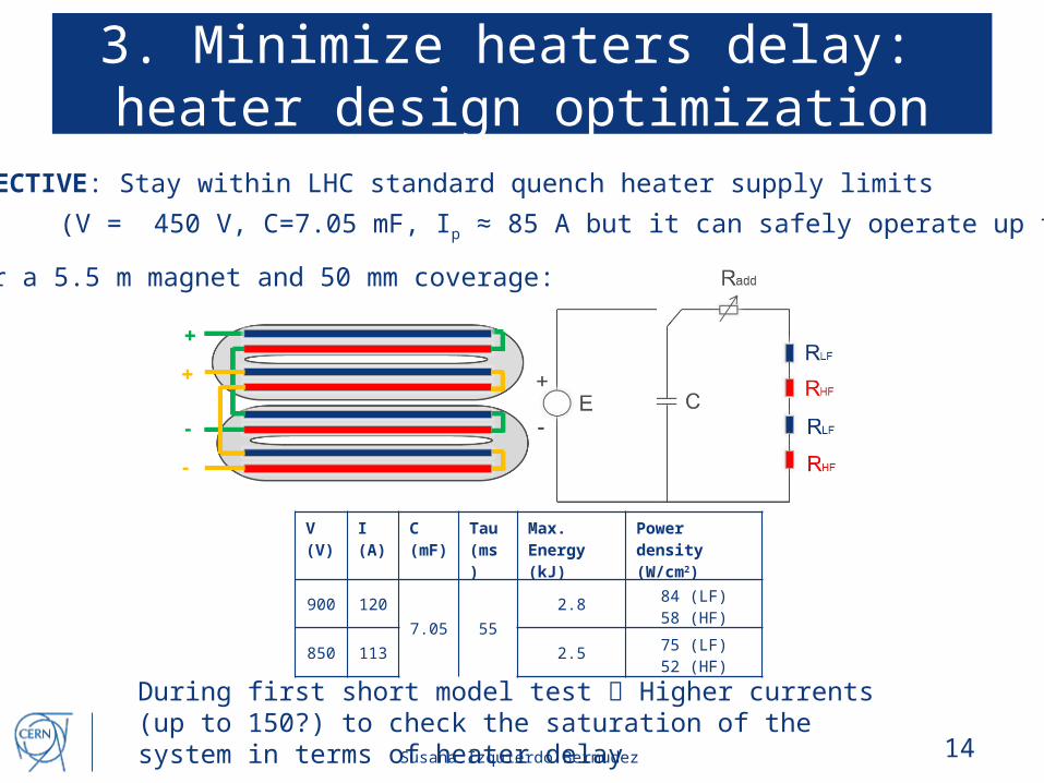
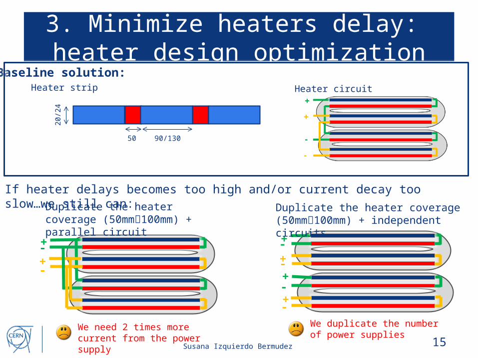
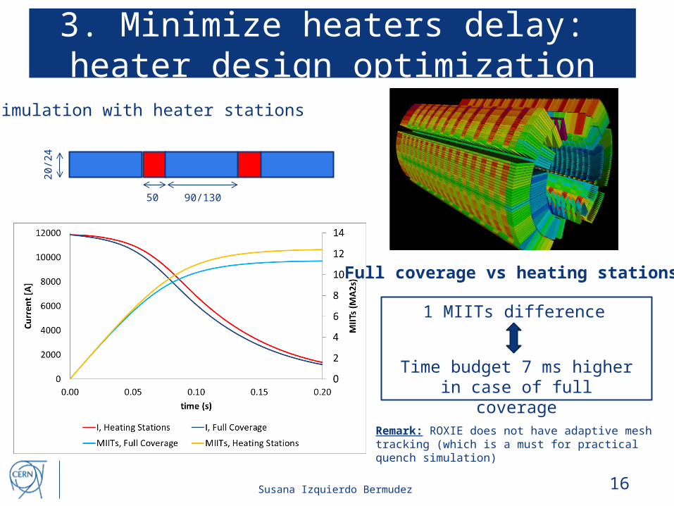
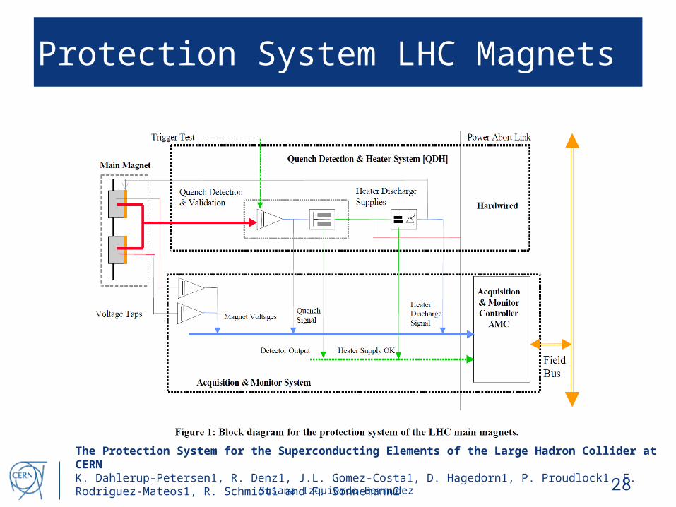
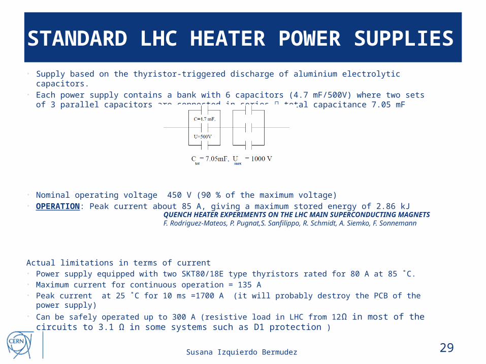
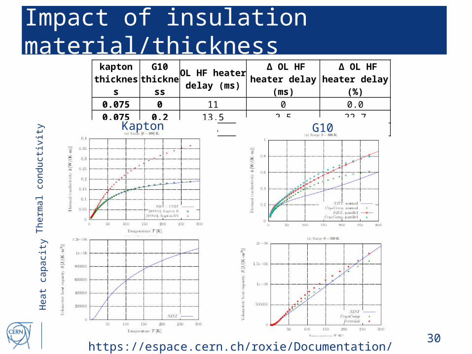