Embed Size (px)
Citation preview

Surveying with TheoLt
Quick start & Hardware guide: Tablet PC
(Fujitsu-Siemens ST 5011d/ST5031) &
Total Station (Leica TCR405)

Training for TheoLt.doc 13/06/2008 11:03 AM
About this document
This training manual was prepared to develop survey and CAD skills in Archaeology. The aim is to achieve competence in basic survey procedure
and basic CAD operations for survey. It is to be used in conjunction with the manufacturers’ guidance on the use of the software and equipment.
It is solely for the application described. The Authors accept no liability for the misuse of equipment or misuse of data acquired using it. The
material in this document is copyright and should not be reproduced without the express permission of the Authors or Latimer CAD.
Aims of this guide
This guide provides the practical information needed to operate TheoLt as a mapping tool and the basic operation of the tablet pc and total
station. The use of real-time CAD as a survey tool requires knowledge of 3 systems which are used concurrently: Total station, TheoLt and
AutoCAD. This guide shows how the 3 systems work together and how users can achieve specific survey outcomes. The specifics of TheoLt are
covered in the installed help TheoLt Release 6 user guide pdf. The AutoCAD advice in this guide is supplementary to the help supplied by
Autodesk in the installed AutoCAD product.
Bill Blake & Imogen Grundon,
Cambridge
28.03.08
1

Training for TheoLt.doc 14/06/2008 6:07 PM
About this document 1 Working with the pen on the Tablet PC 21 Table of contents 2 Recording points with attributed symbols 22 TCR 405 Accessory list 3
Centring & levelling up TCR405 Total station 4 AutoCAD commands you need to know Centring & levelling up: key points to remember 5 1.Frequently used Commands 24
Tablet PC accessory list 6 2.Layers 25 Inserting the PCMCIA Serial adaptor card 7 3.View 26
Fitting the bracket 8 4.Text 27 Using the instrument: navigating the menus 9 5.Inquiry 28
Using TheoLt: key concepts 10 6.Drawing and editing Lines 29 AutoCAD tips for surveying with TheoLt. 10 7.Getting UCS to control views 30
Surveying with TheoLt: basic procedure. 11 Orientation principles 12 Appendix A: Initial set up 31
Moving the instrument. How orientation works 13 Procedure for setting up TCR400 Total station comms 32
Orientation options in TheoLt 14 Communications options 33 Procedure in the field Procedure for setting up TheoLt interface with AutoCAD 34
Orientation 1. Selecting the stations 15 Common interface problems 35 2. Height of instrument 16 Customising AutoCAD toolbars 36
3. Check the results 17 Customising the feature table 37 4. Set out new stations 18 Equipment check list and price schedule: TCR 405
Measuring points using a prism 19 Appendix C
Drawing in AutoCAD as you measure 20 Equipment check list and price schedule: Tablet PC
TCR Accessory list
2

Training for TheoLt.doc 13/06/2008 11:03 AM
TCR Accessory list
1 Data cable May be USB or Serial type
2 Tribrach: laser plummet type, rotate it to fit in the case
3 Charger shoe. Check the battery is properly seated in the shoe when charging
4 Adjustment tools Do not use these unless you know what you are dong! they are vital for aligning the EDM and should be kept with the instrument
5 Spare battery GEB 111 The small battery is only good for about an hour of reflector-less work.
6 Battery GEB 121 2 of these batteries (4hours each) will do a good day’s work.
7 Mains adapter. Care should be taken over the cable; it is easily broken by winding tightly.
8 Pole tip: This is often stored fixed to the mini prism
9 Lens hood and dust cover
10 Manual & Basic Software
11 Mini Prim, Can be either Zero or 18mm offset
12 TCR /Total Station /Theodolite. Always place in the case battery side up
13 Detail pole. In 4 sections. With all 4 sections, tip and prism you have a target height of 1.3m
1
2
3
4
5
6
7
8
9
10 11
12
13
3
Training for TheoLt.doc 13/06/2008 11:03 AM
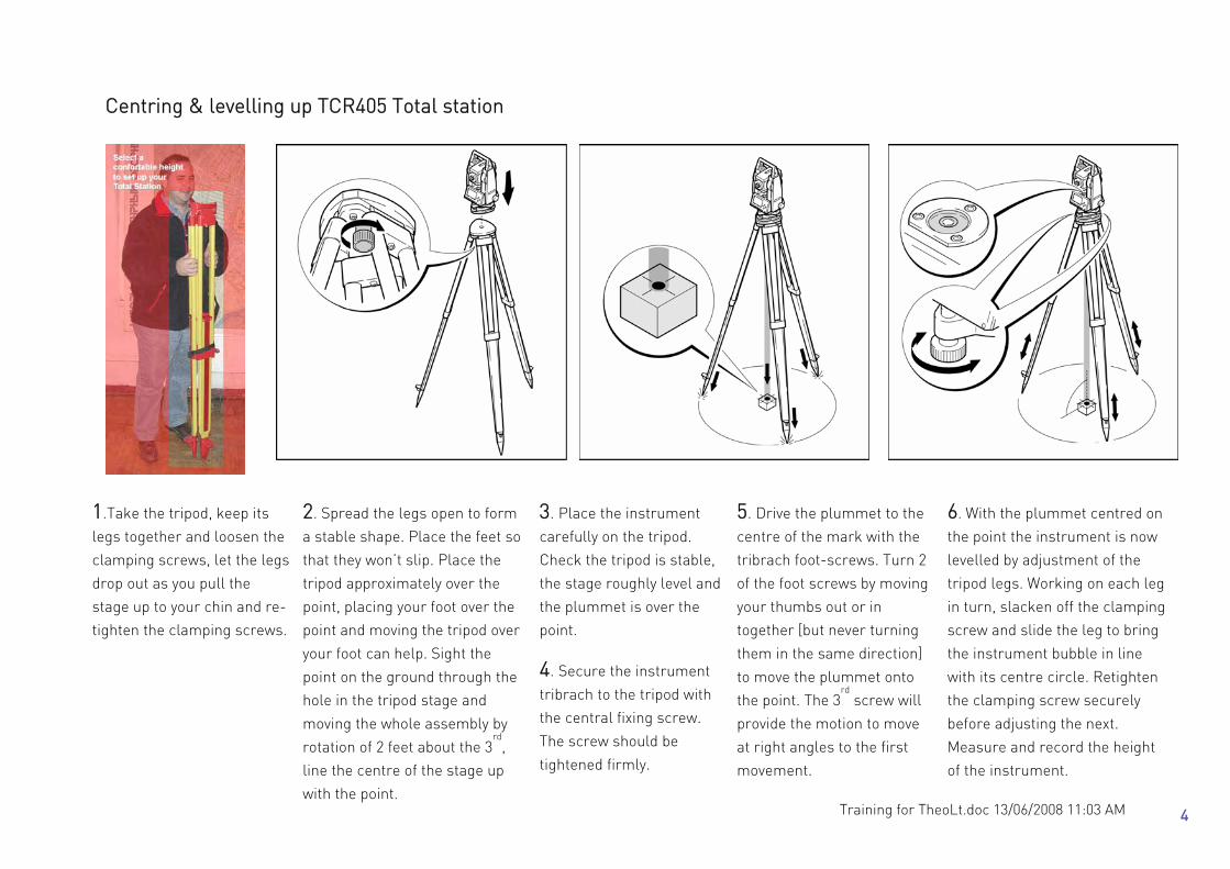
Centring & levelling up TCR405 Total station
1.Take the tripod, keep its
legs together and loosen the
clamping screws, let the legs
drop out as you pull the
stage up to your chin and re-
tighten the clamping screws.
2. Spread the legs open to form
a stable shape. Place the feet so
that they won’t slip. Place the
tripod approximately over the
point, placing your foot over the
point and moving the tripod over
your foot can help. Sight the
point on the ground through the
hole in the tripod stage and
moving the whole assembly by
rotation of 2 feet about the 3rd
,
line the centre of the stage up
with the point.
3. Place the instrument
carefully on the tripod.
Check the tripod is stable,
the stage roughly level and
the plummet is over the
point.
5. Drive the plummet to the
centre of the mark with the
tribrach foot-screws. Turn 2
of the foot screws by moving
your thumbs out or in
together [but never turning
them in the same direction]
to move the plummet onto
the point. The 3rd
screw will
provide the motion to move
at right angles to the first
movement.
6. With the plummet centred on
the point the instrument is now
levelled by adjustment of the
tripod legs. Working on each leg
in turn, slacken off the clamping
screw and slide the leg to bring
the instrument bubble in line
with its centre circle. Retighten
the clamping screw securely
before adjusting the next.
Measure and record the height
of the instrument.
4. Secure the instrument
tribrach to the tripod with
the central fixing screw.
The screw should be
tightened firmly.
4

Training for TheoLt.doc 13/06/2008 11:03 AM
Centring & levelling up: key points to remember ♦ When a total station needs to be set up over a marked point on the ground, place the tripod over the point by eye first,
put your foot over the mark to help. ♦ Before you start check the tribrach foot-screws are at the middle of their runs- there is a mark to show this. ♦ Centre the tribrach before levelling it. If you run out of travel on the foot-screws reposition the whole tripod and start
again ♦ Kick in the feet of the tripod if you are on soft ground and fit the tablet bracket etc. BEFORE making fine adjustments ♦ CENTRE the tribrach over the point with the FOOT-SCREWS ♦ Always work 2 screws and then 1 screw don’t skip from one to another. When you turn two foot-screws move your
thumbs in or out from each other- never turn them the same way! Watch the centre mark to see which way to move it!
♦ Level up the bubble with the TRIPOD leg adjuster clamp screws. By lengthening and shortening each leg in turn you
will rotate the centred axis of the setup about the mark. Use your thumb to hold the weight as you slide the leg, you will be able to have millimetre control that way
♦ When complete the setup procedure must achieve 3 things which are essential for measurements to work. If these
conditions are not met the work will be imprecise and beyond repair! STABLE AND SAFE, clear from wet, dust, wind and traffic (foot, goats, vehicle or otherwise!) Make sure the instrument is clamped to the tribrach. Keep the tablet in the shade and never point the telescope into the sun VERTICALLY CENTERED OVER THE POINT. If it’s not over the mark don’t use it! HORIZONTALLY LEVEL. Keep an eye on the bubble, it will move off centre over time. Use the foot screws to bring it back to level but don’t forget if you adjust the level you will need to check the centring. Small adjustments can be made by carefully unscrewing the central mounting and sliding the tribrach back over the mark.
5

Training for TheoLt.doc 13/06/2008 11:03 AM
Tablet PC - accessory list All of the components are vital. The loss or damage of any one part will render surveying operations in TheoLt impossible. Note that the Fuji needs a serial adapter (2) to connect it to the EDM with the TCR cable (1). The outfit includes 3 batteries and an off-unit charger (3). It is essential to have a minimum of 2 x 9 cell batteries (4). Charged for each day’s work, they deliver about 31/2 hours each. The smaller 6 cell battery (5) is an emergency spare giving about 2 hours.
2
3
4
5
7
1
6 8
6
Training for TheoLt.doc 13/06/2008 11:03 AM
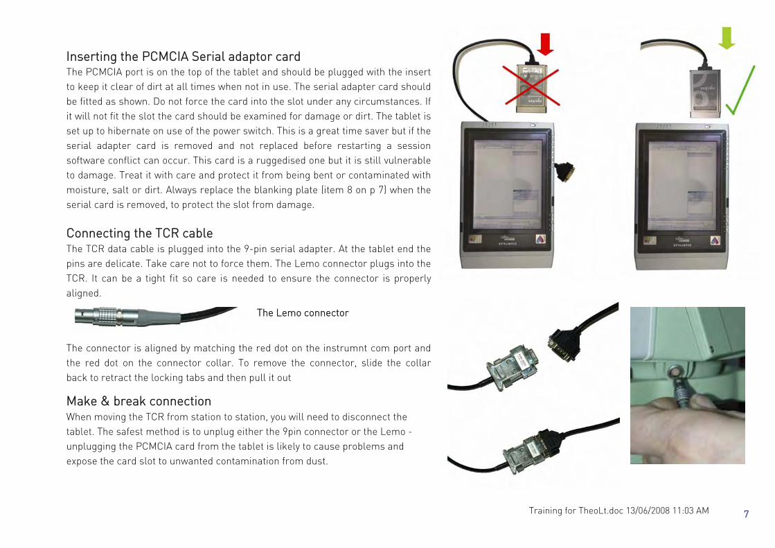
Inserting the PCMCIA Serial adaptor card The PCMCIA port is on the top of the tablet and should be plugged with the insert to keep it clear of dirt at all times when not in use. The serial adapter card should be fitted as shown. Do not force the card into the slot under any circumstances. If it will not fit the slot the card should be examined for damage or dirt. The tablet is set up to hibernate on use of the power switch. This is a great time saver but if the serial adapter card is removed and not replaced before restarting a session software conflict can occur. This card is a ruggedised one but it is still vulnerable to damage. Treat it with care and protect it from being bent or contaminated with moisture, salt or dirt. Always replace the blanking plate (item 8 on p 7) when the serial card is removed, to protect the slot from damage. Connecting the TCR cable The TCR data cable is plugged into the 9-pin serial adapter. At the tablet end the pins are delicate. Take care not to force them. The Lemo connector plugs into the TCR. It can be a tight fit so care is needed to ensure the connector is properly aligned.
The Lemo connector
The connector is aligned by matching the red dot on the instrumnt com port and the red dot on the connector collar. To remove the connector, slide the collar back to retract the locking tabs and then pull it out
Make & break connection When moving the TCR from station to station, you will need to disconnect the tablet. The safest method is to unplug either the 9pin connector or the Lemo - unplugging the PCMCIA card from the tablet is likely to cause problems and expose the card slot to unwanted contamination from dust.
7

Training for TheoLt.doc 13/06/2008 11:03 AM
Fitting the bracket The bracket (item 6 on p7) is designed for use with a survey tripod. It will fit
both Wild and Zeiss pattern tripods. The spring steel clip must be fully engaged
into the accessory slot on the tripod head and the strut correctly slotted home
to form a secure platform for the tablet. The bump case (item 7 on p7) is
supplied with Velcro patches for additional security: they will need to be
pressed home.
Care should be taken to avoid upsetting the instrument level when mounting
and de- mounting the bracket.
The bracket is designed for use with the tablet in its bump-case: it will be a
loose fit if the case is not used. Once the tablet PC is mounted to the tripod and connected to the TCR the
instrument should be re-levelled and centred as fitting the tablet often causes
a slight dislevelment!
8

Training for TheoLt.doc 13/06/2008 11:03 AM
Using the instrument: navigating the menus
The TCR 400 series uses a 5 key menu navigation system. The navigation key will allow scrolling between menu options; the page
key will allow selection of pages within menus. There is some variation in the menu layout depending on the year of instrument
manufacture. In addition to the front panel keys a configurable trigger key (the’ banana’ button) on the side panel of the instrument
can be set to measure and record (the ‘all’ function in the measure screen). Note the banana button may bet set to ‘off’, ‘distance
only’ or ‘all’ from the settings menu Trigger key option)
IR and RL modes IR = infra-red and RL = reflector-less. IR mode requires a reflector or prism (Item 11 on p4) to work. RL uses zero (it is set by
default when RL is selected) Check that the prism offset (in the instrument EDM settings menu) is set to 18mm or zero when using the mini-
prism. This is important when selecting the EDM mode to IR as the prism selected MUST have the correct offset.
1 Selected filed Indicates the field of user or measured input 2 Status Symbols Indicates measurement mode (IR or RL),
battery state and menu options 3 Fixed Keys Page Scrolls to next page when dialogue consists of
several pages Menu Accesses programs and settings User Customisable with function from the func
menu Func Quick access to measurement support
functions
Enter Sets selected option
Esc Returns to previous screen
4 Navigation Key Menu navigation, focus scrolling and option
selection
5 Function keys Assigned to variable functions displayed on
the softkey bar
6 Softkey bar Functions available on current screen
1
2 3
3
5
6
4
9
Training for TheoLt.doc 13/06/2008 11:03 AM
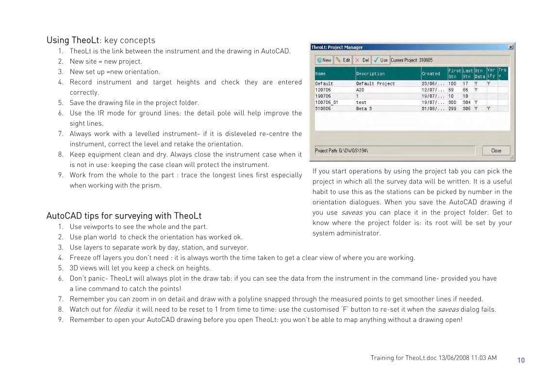
Using TheoLt: key concepts 1. TheoLt is the link between the instrument and the drawing in AutoCAD. 2. New site = new project. 3. New set up =new orientation. 4. Record instrument and target heights and check they are entered
correctly. 5. Save the drawing file in the project folder. 6. Use the IR mode for ground lines: the detail pole will help improve the
sight lines. 7. Always work with a levelled instrument- if it is disleveled re-centre the
instrument, correct the level and retake the orientation. 8. Keep equipment clean and dry. Always close the instrument case when it
is not in use: keeping the case clean will protect the instrument. 9. Work from the whole to the part : trace the longest lines first especially
when working with the prism. AutoCAD tips for surveying with TheoLt
1. Use veiwports to see the whole and the part. 2. Use plan world to check the orientation has worked ok. 3. Use layers to separate work by day, station, and surveyor. 4. Freeze off layers you don’t need : it is always worth the time taken to get a clear view of where you are working. 5. 3D views will let you keep a check on heights. 6. Don’t panic- TheoLt will always plot in the draw tab: if you can see the data from the instrument in the command line- provided you have
a line command to catch the points! 7. Remember you can zoom in on detail and draw with a polyline snapped through the measured points to get smoother lines if needed. 8. Watch out for filedia it will need to be reset to 1 from time to time: use the customised ‘F’ button to re-set it when the saveas dialog fails. 9. Remember to open your AutoCAD drawing before you open TheoLt: you won’t be able to map anything without a drawing open!
If you start operations by using the project tab you can pick the project in which all the survey data will be written. It is a useful habit to use this as the stations can be picked by number in the orientation dialogues. When you save the AutoCAD drawing if you use saveas you can place it in the project folder. Get to know where the project folder is: its root will be set by your system administrator.
10
Training for TheoLt.doc 13/06/2008 11:03 AM
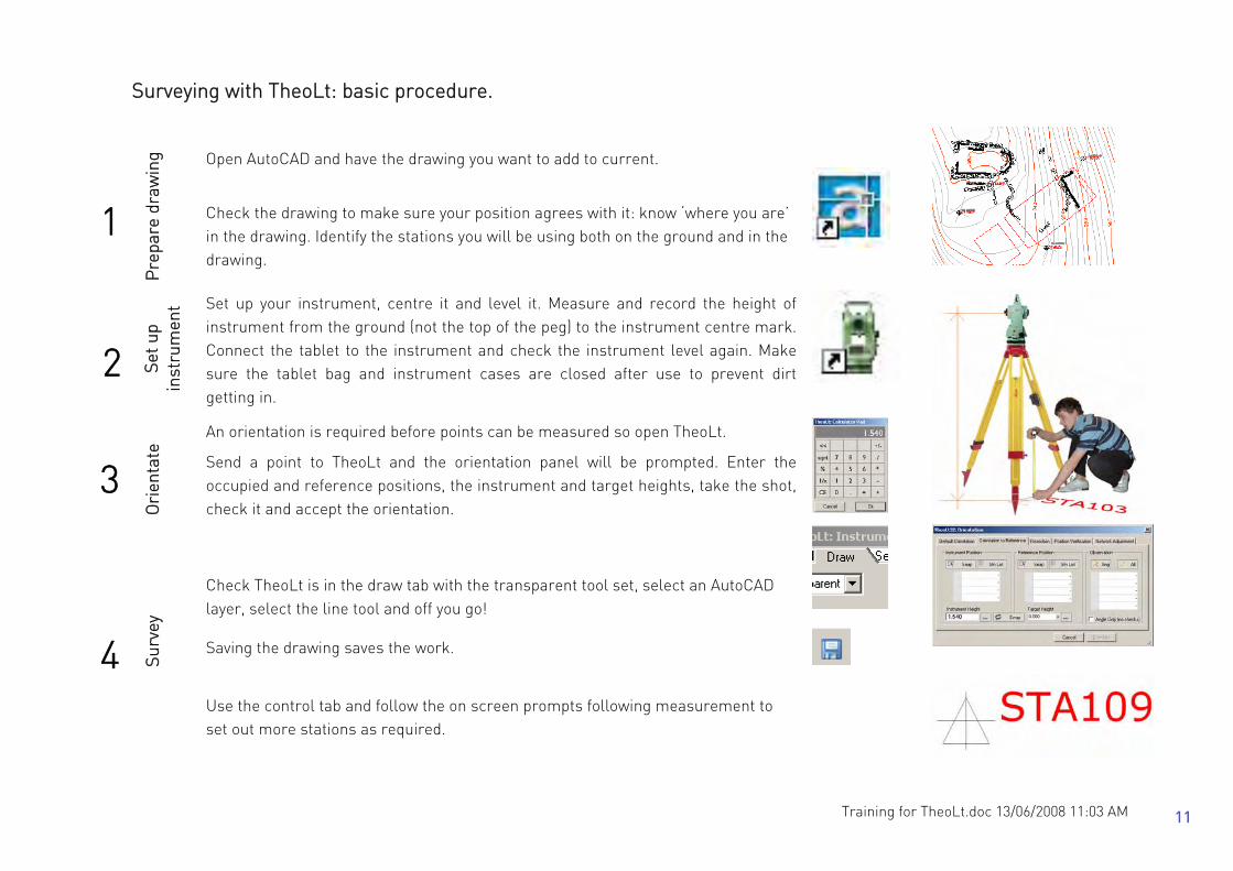
Surveying with TheoLt: basic procedure.
Open AutoCAD and have the drawing you want to add to current.
1
Pre
pare
dra
win
g
Check the drawing to make sure your position agrees with it: know ‘where you are’ in the drawing. Identify the stations you will be using both on the ground and in the drawing.
2 Set u
p in
stru
men
t Set up your instrument, centre it and level it. Measure and record the height of instrument from the ground (not the top of the peg) to the instrument centre mark. Connect the tablet to the instrument and check the instrument level again. Make sure the tablet bag and instrument cases are closed after use to prevent dirt getting in.
An orientation is required before points can be measured so open TheoLt.
3
Ori
enta
te
Send a point to TheoLt and the orientation panel will be prompted. Enter the occupied and reference positions, the instrument and target heights, take the shot, check it and accept the orientation.
Check TheoLt is in the draw tab with the transparent tool set, select an AutoCAD layer, select the line tool and off you go!
Saving the drawing saves the work.
4 Surv
ey
Use the control tab and follow the on screen prompts following measurement to set out more stations as required.
11

Training for TheoLt.doc 13/06/2008 11:03 AM
Orientation principles Surveying can only work with an orientation. Unless you can place yourself (and your instrument) at a known point on the map and determine a fixed direction from which measurements can be made you cannot survey! TheoLt offers 2 methods (orient to reference and resection) for achieving orientation on moving the instrument to occupy a new point.
Known positions must be marked. A station point should be recoverable and therefore it is marked by a nail, peg, pencil or incised mark. It is essential the same point can be found and identified WHITH CERTAINTY .If a mark is to be left for future use it should be of adequate permanence. Do not use any mark for survey unless you are confident it is identified as a survey point with verified co-ordinates!
On moving the instrument to a new position there are 2 methods of achieving orientation; both require 2 clearly identifiable marked points. If the 2 points are inter-visible orientation to reference is possible if the 2 points can be seen from a 3
rd
resection is possible. Resection is the solution of triangles to determine an unknown position by measurement to 2 (or more) known positions a new instrument position can be added to the survey. Instrument heights are crucial. If a station is occupied with an incorrect height of instrument entered a false height value will be transferred to every point measured form it. Always measure and record the height of the instrument once you have levelled it. Target heights are crucial. Always check that the height of the target is correct, particularly after orientation when the reference target height can be carried forward and when switching to reflector-less modes when a target height of zero is required. Levelling and centring the instrument correctly is vital, follow the procedure on p4. Do not take measurements until the instrument is in a fit state to do so!
Being positive about station positions is vital, a witnessing diagram like this saves time and error and is well worth the time taken to prepare!.
12

Training for TheoLt.doc 13/06/2008 11:03 AM
Moving the instrument: How orientation works Orientation to reference = Occupying 2 known points: Orientation to reference requires the Identification of the position of occupation and position of reference on the ground and on the survey drawing. By measuring the angles and distance between 2 known points the orientation is achieved. Resection = Occupying an unknown point: To resolve the occupied position measurement to a minimum of 2 identified positions of reference is required. Resection allows you to set out a station where you want to be provided you have lines of sight to 2 other stations or reference positions. If the geometry of the resection is poor it will be indicated in the position verify table: often the remedy for poor results is to move the instrument to a better position with improved geometry (i.e.: less steep angles or less variation in distances: the triangle you are solving should be ‘well conditioned’).
13
Training for TheoLt.doc 13/06/2008 11:03 AM
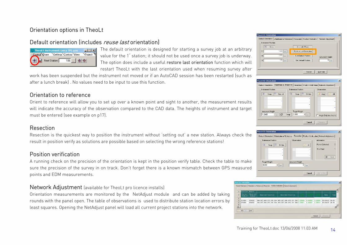
Orientation options in TheoLt Default orientation (includes reuse last orientation)
The default orientation is designed for starting a survey job at an arbitrary value for the 1
st
station; it should not be used once a survey job is underway. The option does include a useful restore last orientation function which will restart TheoLt with the last orientation used when resuming survey after
work has been suspended but the instrument not moved or if an AutoCAD session has been restarted (such as after a lunch break) . No values need to be input to use this function. Orientation to reference Orient to reference will allow you to set up over a known point and sight to another, the measurement results will indicate the accuracy of the observation compared to the CAD data. The heights of instrument and target must be entered (see example on p17). Resection Resection is the quickest way to position the instrument without ‘setting out’ a new station. Always check the result in position verify as solutions are possible based on selecting the wrong reference stations! Position verification A running check on the precision of the orientation is kept in the position verify table. Check the table to make sure the precision of the survey in on track. Don’t forget there is a known mismatch between GPS measured points and EDM measurements. Network Adjustment (available for TheoLt pro licence installs) Orientation measurements are monitored by the NetAdjust module and can be added by taking rounds with the panel open. The table of observations is used to distribute station location errors by least squares. Opening the NetAdjust panel will load all current project stations into the network.
14

Training for TheoLt.doc 13/06/2008 11:03 AM
Pick the station you are on
here. You can pick it off the
drawing using the snap option
or select it from the station
list held in the project file.
Enter the height of instrument here. You can use the popup keypad.
Procedure in the field 1.Selecting the stations
If you have 2 points on your survey with known positions (marked in
AutoCAD with station symbols) you can use orientation to reference to
align your work with the survey. Set up the instrument over one point and
a prism over the other, select the control tab and then open the
orientation panel, select the orient to reference tab and enter the station
details need for the observation to record the orientation.
If you have the co-ordinate values for the stations they can be added
using the ‘new’ option from the ‘Stn List’ option next to snap. The
stations will be added to the drawing and the project station list. If you want to start a new drawing and add stations to the stn list (for example as a sub survey) you can insert the required stations into the current drawing using the Insert stn/insert ref option. You can also update the stn list by keying in the station co-ordinates with the ‘new’ option and then insert them into the drawing if you need to.
15
Training for TheoLt.doc 13/06/2008 11:03 AM
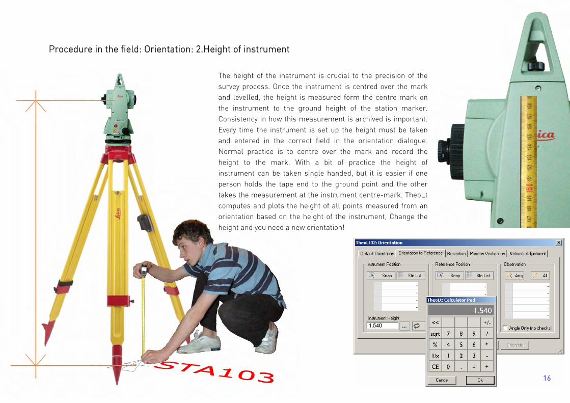
Procedure in the field: Orientation: 2.Height of instrument
The height of the instrument is crucial to the precision of the survey process. Once the instrument is centred over the mark and levelled, the height is measured form the centre mark on the instrument to the ground height of the station marker. Consistency in how this measurement is archived is important. Every time the instrument is set up the height must be taken and entered in the correct field in the orientation dialogue. Normal practice is to centre over the mark and record the height to the mark. With a bit of practice the height of instrument can be taken single handed, but it is easier if one person holds the tape end to the ground point and the other takes the measurement at the instrument centre-mark. TheoLt computes and plots the height of all points measured from an orientation based on the height of the instrument, Change the height and you need a new orientation!
16

Training for TheoLt.doc 13/06/2008 11:03 AM
With the 2 points identified, point the TCR at the reference target and take the orientation shot: the observation result is displayed in the H V Ds panel
The difference between the CAD positions and the measured position is shown as both the distance and height displacement (dD and dH) the values are shown in metres.
Further confirmation of the orientation result can be obtained by using the position verification tab; take a shot to the reference target and the result is displayed: it can be logged to a file using the save option if desired.
Procedure in the field: Orientation: 3.Check the results
17

Training for TheoLt.doc 13/06/2008 11:03 AM
Procedure in the field: Orientation: 4.Set out new stations Control Tab If instrument measurements are made with TheoLt in the control tab the Control Type dialogue opens to allow a target height to be added and for selection of the station symbol type. To distinguish between occupied stations and reference only stations the circle option is available. Stations may be inserted as either a foresight shot or resection (some tines known as ‘free’ stations). End over end working means that the occupation of stations is reversed once the station is set out.
Target quality and precision Ideally, for optimum precision, a prism is set up mounted on a 2nd tribrach over the forward station, the height recorded and the station added to the survey. The precision of station positions is compromised if working with a single tripod as the prism will be hand held or a reflector-less measurement used. It may be wise to set-out a local reference if you are working from stations of good precision to points set-out with a handheld prism to reduce the forward transmission of error. Target height On setting out the station there is an opportunity to reset the target height in the Control Type dialog, this will override the target height setting in the TheoLt toolbar.
18

Training for TheoLt.doc 13/06/2008 11:03 AM
The last used heights are stored for reuse. Zero is always available for RL mode.
The last used heights are stored for reuse. Zero is always available for RL mode.
The height of target with a single section of pole and tip is 0.4m
The prism bubble must be centred so that the pole is vertically over the point of measurement.
Procedure in the field: measuring with the prism When using the instrument in IR mode, the height of the prism above the point of measurement needs to be corrected for. Observations to the prism require the use of a target height in TheoLt to make sure the measured point is recorded at the ground height. REMEMBER the target height is set with the tick button to confirm it!
The target height with the 4 sections fully assembled detail pole is 1.3m
19

Training for TheoLt.doc 13/06/2008 11:03 AM
Make sure TheoLt is set to the draw tab. Use the transparent setting for AutoCAD commands and select a drawing tool e.g. line. The TheoLt drawing tools are useful you want to plot a circle or arc.in 3D.
Watch the command line:
the instrument data should
appear here as well as the
status of any command you
are using. Make sure lines
are plotted!
The TheoLt history will allow you to go back and redraw lines if you forget to use the line command. Pick on the observation and it is sent to the command line again. The default setting is for the last 10 observations to be stored in the history.
TheoLt will always plot lines
to WCS regardless of the
current UCS. You can use
any UCS you like to get the
view or edits you want.
Drawing in AutoCAD as you measure
20

Training for TheoLt.doc 13/06/2008 11:03 AM
Working with the Pen on the Tablet PC There are 3 methods of entering commands into AutoCAD: The pull-down menu, the toolbar buttons and keyboard entry in the command line. The tablet on-screen keyboard is awkward, not least because of the shift in window focus needed to use it. If the keyboard is docked to the system tray at the bottom of the windows screen it is reasonably predictable. However, it has a tendency to
hide or pop up and interrupt command sequences. If you know the keyboard alias for a command (e.g L for line) and you can’t find a button for it, the on-screen keyboard gets you there as a last resort! The tablet pc will have a shortcut to the on-screen keyboard fixed on the taskbar,
Functions on the pen Tablets PCs for AutoCAD use an active pen. This means the pen is a substitute for a mouse and it can serve all mouse functions other than scroll. Pick- tap on the item and it will be selected. In the AutoCAD drawing area, selected items will appear ‘gripped’ or highlit by its snap points. Right click- squeeze the switch on the side of the pen, tap the pen to the screen and release: this takes some practice! Double click – it is often better to use a right click and select from a context menu as the double click response on the pen is poor Enter-double tap, this can be slow so an alternate is the hard enter button on the tablet (see p 18) or enter on the on screen keyboard. Tool-tips if you ‘hover’ the pointer over an AutoCAD button its tool-tip should be revealed, indicating its function. (this does not apply to TheoLt). Pen action in AutoCAD A tap in the drawing area in AutoCAD while the line is running will pick an accidental ‘next point’ it will be a 2D point with a zero height and useless for the survey. This is to be avoided and repaired immediately. If you draw a line, make sure it is snapped onto objects of the right height! The line command can be stopped and started by using a double right click in the drawing area to act as an ‘enter’ which repeats the last command in AutoCAD.
21

Training for TheoLt.doc 13/06/2008 11:03 AM
Recording point finds with attributed point symbols
The TheoLt Features command The features command gives access to point symbols which have attributes logged to an Excel comma space value delimited (csv ) data file The command is accessed via the TheoLt tools, when Features is selected the features palette will open: a double click on an icon in the palette will launch the dialog for symbol insertion. Should the palette not be displayed reselect the features option after returning to the transparent option. Point symbol The symbol picked from the palette is inserted into the current drawing at the position of instrument observation. It is tagged with the attributes given to it at capture. Orientation of the symbol is fixed to the current UCS (so use WCS for consistency to the survey grid) . The symbol is inserted into the current layer, it will be coloured by the current layer colour. The block size and annotation text style is determined by the prototype block drawing in the folder c:\theoltblocks . Inputting attributes When the shot to the point is taken the next option opens the Insert feature Data dialog is prompted to accept the attributes required. Each field is selectable and editable. Data entered into this panel cannot be undone so care should be taken to avoid erroneous entry! The OK button writes the data to the CSV file and inserts the symbol into the drawing. New attribute names can be typed into the pull down last used list. Context number A context number defines a specific deposit or feature in archaeological recording. It is important because all finds retrieved from that feature or deposit are located by the context number they are given. The Context symbol may be used to identify a context with a co-ordinated point.
22

Training for TheoLt.doc 13/06/2008 11:03 AM
The symbol in the drawing The point symbols on the plan mark the point of capture but also ( in the case of surface finds) can be used as nodes for the contour model so careful checking of instrument and target heights is needed to keep the 3D record precise. The CSV file The data is written to a .csv file in the project folder (e.g.smallfind.csv) that can be read in Excel. The fields will be tabulated as columns. The first field will determine the row order by default. If a database with fixed fields is needed, a mask can be used to constrain the fields. The mask table is shown at Customising the feature attribute table on p 36. Note that the file cannot be written to while it is open! AutoCAD attribute editor The AutoCAD attribute editor (double-click on an inserted block) will reveal the attributes attached to the block but not the full attribute list as this is written to the CSV file, it is a useful check on point numbering and confirmation of a successfully inserted block.
23

Training for TheoLt.doc 13/06/2008 11:03 AM
AutoCAD commands you need to know 1: Frequently used commands Command Icon What it does Command Icon What it does Line
Draws a segmented line through the measured points.”C” closes a line back to its first point. This is the basic mapping tool.
Snap to insert
The insert point is the true co-ordinate position of a station in WCS, if you want to check a station co-ordinate list ins of is one way to do it.
Hard Esc Clears grips
Hard Enter
Repeats last command
Layer
Don’t forget it’s easy to change the layer an item is on by picking it and then selecting the required layer from the pull down list in the standard toolbar.
Cancel*
Cancel (^c^c) clears the command line but NOT grips: you will need to customise a button for this command.
List
Displays the properties of the chosen object
Offset
Copies an object at a set distance parallel to it, It works relative to current UCS the ‘t’ option (for through point) will allow a picked point to set the offset distance.
3Dpolyline
If you need to plot a continuous line as a single entity (rather than a series of segments with line) Use 3Dpolyline as a standard Polyline will not work with instrument data as it is a 2D command.
Extend
Lengthens a line in its own direction towards another line in the same z plane.
Trim
Lengthens a line in its own direction towards another line in the same z plane.
Filedia*
If AutoCAD fails to display the file list when using open or saveas cancel the command and use the’ f’ button to reset it.
Plan*
Plan View – this command returns to a flat view from above after a 3D orbiting command
Undo redo safer than erase for dealing with mistakes
Copy
Be careful to pick the start point in CAD so TheoLt can send the displacement points to the command line
3D pan, zoom Orbit
Also zoom extents, zoom previous
* These commands do not have preloaded icons in AutoCAD; you will have to customise your toolbar accordingly.
24

Training for TheoLt.doc 13/06/2008 11:03 AM
AutoCAD commands you need to know 2: Layers Current Layer
AutoCAD drawings separate information by layers. The layers in a drawing overlay each other to build up the complete picture. TheoLt
plots into the current layer. It automatically sets the working layer (current layer) to a pre-assigned layer when a station is inserted; take
care to reset the current layer to the right one for the details you map. Changing layer assignment
Specific features, should be separated by placing them in an appropriate layer. If you make a mistake, you can always reassign the layer using match properties or the property browser.
Distinguishing layers When more than one is visible, distinguishing different layers is best done by choosing different colours, line weights or line types for each layer. Remember these should be bright colours as pale colours are not easily visible in the harsh light on site. Make them distinctively different from each other, so you don’t forget. Managing layers
The Layer Properties Manager, reached through the ‘stack of papers’ icon to the far left of the layers bars, governs the layers and their current status. Here you can create layers,
select one to be your current layer – ie the one you actively draw in. Here too, you can turn off any or all of the layers to make the screen as easy to work in as possible. The current layer can be assigned by selecting from the pull-down layer list. Creating a new layer – click on the ‘New’ button. Double click on the default name ‘Layer 1’ and it allows you to rename as you wish. On – (toggle) – lit light bulb means the layer is visible in the active drawing. Freeze – (toggle) – means that the layer content will not be visible in the current view port. Lock – (toggle) - means the layer contents can’t be edited.
25

Training for TheoLt.doc 13/06/2008 11:03 AM
AutoCAD functions you need to know 3: View Pan, Zoom and 3D Orbit These are three of the most used tools. They do not alter the drawing; they alter your view of it. Use right-click in mid command to switch viewing modes or exit.
Real-time pan, as in pdf files, allows you change the view without changing the apparent scale, Pan allows you to grab the drawing and move in any direction
The Zoom function has several choices of zoom. The most used are: Real-time Zoom, In and Out – these are familiar to most people from graphics software or print previews in Word, and needs no further explanation
Zoom Extents – this is a valuable zoom, because it takes you out to show the full drawing on screen. If a station input has gone wrong, then this is where you are most likely to spot that something has been inserted far from where it should be.
Zoom Window – allows you to draw a window round the object onto which you wish to zoom, and homes directly in on it. Zoom Previous – is a shortcut to the last view you had on the screen
3D Orbit allows you to rotate the drawing in 3D, Move the pointer inside the circle and the plane of view rotates, move outside and the view rotates so you can see the terrain on which you are surveying, showing gradient and the vertical relationship between the features or trenches you are recording.
These are all you will ever really need to use, but experiment if you want to, it’ll do no harm to learn as you go.
26
Training for TheoLt.doc 13/06/2008 11:03 AM
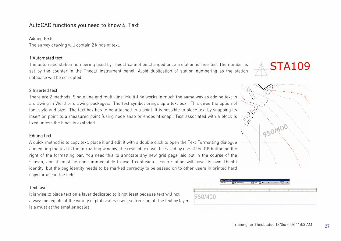
AutoCAD functions you need to know 4: Text Adding text: The survey drawing will contain 2 kinds of text. 1 Automated text The automatic station numbering used by TheoLt cannot be changed once a station is inserted. The number is set by the counter in the TheoLt instrument panel. Avoid duplication of station numbering as the station database will be corrupted. 2 Inserted text There are 2 methods. Single line and multi-line. Multi-line works in much the same way as adding text to a drawing in Word or drawing packages. The text symbol brings up a text box. This gives the option of font style and size. The text box has to be attached to a point. It is possible to place text by snapping its insertion point to a measured point (using node snap or endpoint snap). Text associated with a block is fixed unless the block is exploded. Editing text A quick method is to copy text, place it and edit it with a double click to open the Text Formatting dialogue and editing the text in the formatting window, the revised text will be saved by use of the OK button on the right of the formatting bar. You need this to annotate any new grid pegs laid out in the course of the season, and it must be done immediately to avoid confusion. Each station will have its own TheoLt identity, but the peg identity needs to be marked correctly to be passed on to other users in printed hard copy for use in the field. Text layer It is wise to place text on a layer dedicated to it not least because text will not always be legible at the variety of plot scales used, so freezing off the text by layer is a must at the smaller scales.
27

Training for TheoLt.doc 13/06/2008 11:03 AM
AutoCAD functions you need to know 5: Inquiry Measuring distance: dist command
This measures the distance between two points, as well as the x,y and z values between them. It gives the angle between the two, and relative to the default AutoCAD WCS angle origin (with zero/360 degrees horizontally to the right). It is a very useful tool for gauging the actual distance between grid pegs or features and the difference in height (z) between the two. The dist command does not report
horizontal distances as such but shows the components in the xx yy axes.: Note that the insertion point of a station block is its true position, its easy to snap to a line end point by mistake! Command: dist Specify first point: ins of (pick a station symbol in the drawing)
Specify second point: Ins of (pick a station symbol in the drawing)
Distance = 10.735, Angle in XY Plane = 270, Angle from XY Plane = 22 Delta X = -0.009, Delta Y = -9.987,
Delta Z = 3.939
Locate Point, or Point ID.
This is very useful for instant 3D coordinates (in the current UCS, set UCS to world for the full site co-ordinates) of any point on the survey. Particularly useful when checking you are using or sighting to the correct station.
List. This lists all the available details of a selected object: angles, coordinates, layers, line types, weights and colour and all relevant information about that selected object.
Area and Volume: Neither of these is of any particular use in this. Area is valid from a vertical viewpoint only and gives no indication of the actual surface area of the site, which is considerably greater. Volume is useful only if you want to calculate the volume of earth moved, say, from a particular trench. However, you have to have pre-excavation levels of the ground surface for this to work.
28
Training for TheoLt.doc 13/06/2008 11:03 AM
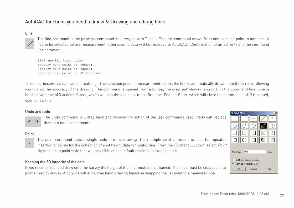
AutoCAD functions you need to know 6: Drawing and editing lines Line
The line command is the principal command in surveying with TheoLt. The line command draws from one selected point to another. It has to be selected before measurement, otherwise no data will be recorded to AutoCAD. Confirmation of an active line is the command line comment:
LINE Specify first point: Specify next point or [Undo]: Specify next point or [Undo]: Specify next point or [Close/Undo]:
This must become as natural as breathing. The selection prior to measurement means the line is automatically drawn onto the screen, allowing you to view the accuracy of the drawing. The command is opened from a button, the draw pull-down menu or L in the command line. Line is finished with one of 3 actions. Close , which will join the last point to the first one. End or Enter, which will close the command and, if repeated, open a new line. Undo and redo
The undo command will step back and remove the action of the last commands used. Redo will replace them but not line segments!
Point The point command plots a single node into the drawing. The multiple point command is used for repeated insertion of points for the collection of spot height data for contouring. From the Format pull-down, select Point Style, select a point style that will be visible as the default mode is an invisible node.
Keeping the 3D integrity of the data If you need to freehand draw onto the survey the height of the line must be maintained. The lines must be snapped onto points fixed by survey. A polyline will allow free hand drawing based on snapping the 1st point to a measured one.
29

Training for TheoLt.doc 13/06/2008 11:03 AM
AutoCAD functions you need to know 7: Getting UCS to control views, Using UCS,
The User Coordinate System (UCS) determines the origin and direction of the x, y & z axes It determines the behaviour of all 2D commands and the z direction of 3D ones. It is a useful tool for controlling the alignment of hand-drawn edits and the controlling views, particularly in 3D. The default co-ordinate system is World (referred to as WCS). In WCS the CAD co-ordinate system is coincident with
the GPS survey grid. A UCS is like a piece of graph paper which can be placed on any plane so that it can be drawn on. TheoLt will always plot in the WCS regardless of the UCS current in the drawing. A UCS can be set up so that an elevation view can be found quickly (using plan> C) or so that polylines can be used to trace from a drawing or photograph on to the survey. A UCS can be made by: ♦ aligning it to an object (UCS>O), ♦ by picking 3 points for the axes (UCS>3p) , ♦ by rotation about one of its 3 axes (e.g. UCS >x>90). ♦ or by assigning it to be parallel to a view Once a UCS is created it can be saved (UCS>s) and re-invoked as required. Controlling views with UCS The default view of WCS is as looking down or ‘plan view’. if a view is needed of a particular elevation one method is to rotate the UCS about its x axis by 90 deg and then use plan to current UCS (plan>C) to see the view. Getting an elevation view A more controlled method is (with the current UCS set to world) to trace a polyline at right angles to the required view (a polyline is used because it will be a level line in 3D). A UCS is aligned to the polyline (UCS>O>pick the polyline). Plan>C will reveal the view. The UCS can then be rotated about the appropriate axis to get the required orientation. Plan C will reveal the effect of each change to the UCS. This method will achieve a true elevation view as it is based on a level line. Polyline
Polyline is a tool for getting fine continuous lines (such as 1:20 scale line work for ‘stone by stone’ drawing). It can be smoothed using pedit. Polylines are 2d continuous string lines. Polyline cannot be used to draw with TheoLt because it is a 2D entity and TheoLt works with 3D data.
30
Training for TheoLt.doc 13/06/2008 11:03 AM
Appendix A:
Initial set up of Instrument communications,
TheoLt interface &
AutoCAD menus
31

Training for TheoLt.doc 13/06/2008 11:03 AM
Procedure for setting up TCR400 Total station comms There are 3 things you will need to establish to do this: 1 The Com settings used on the instrument 2 The instrument communications are set to the RS232 com port 3 The Serial port number on the tablet 1. Set the instrument comms to the defaults The comms settings are under the Menu button> F2 (for settings)>, page to page 2> select communication parameters: set them to the defaults. 2. Set the TCR to use the data port Press Menu> F2 (for settings) >page to page 3 then switch the instrument Data output from Int.mem to RS232 by using the scroll keys.> Select with the F4 (indicated ‘ok’) button. 3. Use TheoLt to set the coms on the tablet to agree with the instrument
Open TheoLt, Go to the settings tab and click on the spanner icon. Select the instrument tab in the settings panel and then select the instrument and its com port. Using the extended options button to the right of the Serial port
field reveals the settings for the port. Set the port to agree with the instrument. Action the changes in the settings panel using the apply button and TheoLt will prompt for a restart to reset the comms. The serial port number on the Fuji (with the PCMCIA card adapter fitted) is shown in the control panel> system>hardware> device manger> ports, com &LPT Testing the interface: measuring and recording points To test the comms the instrument should be set to measure in reflector-less mode, the cable connected and triggered by either the all key indicated at the measure screen on the instrument or the all button on TheoLt. TheoLt will respond with an orientation prompt.
32

Training for TheoLt.doc 14/06/2008 6:06 PM
Communications options ‘Recording to RS232?’ message After switching on the TCR the first measurement sent from the instrument will prompt confirmation of the interface; accept the request with the indicated ‘ok’ key.
Note on USB connection Leica has supplied TCRs with a USB cable [Art No:GEV 189 ] from late 2004 onward. The cable will ONLY work with specific drivers for it and the virtual com port assignment correctly made, USB serial comms can reassign COM port numbers when the cable is plugged into the PC, this can be ok but often the Comport numbers get beyond the permitted range of1 to 8. If your system has more than one USB port make sure the drivers are loaded for each port by plugging the cable into each one and following the ‘new hardware found’ prompts. Note on Bluetooth comms: It is possible to use Bluetooth to replace the cable connection to the TCR this can be either by using a serial adaptor or by using a BT port on a total station (e.g Leica TCR1200 series). Like USB Bluetooth uses a virtual port mapping method which can reassign the Com port number. Bluetooth serial ports must be in the range 1 to 8. The comms settings for Bluetooth will be set in the same way as for standard coms. There are a variety of Bluetooth configuration interfaces (e.g Toshiba, Widcom etc) depending on the hardware type present on the system. If possible first time set up should be made using ‘custom’ settings rather than ‘automatic’ to allow for Com port assignment. Note on trigger key (banana button) The interface may appear to be disabled because of the configuration of the trigger key. The key (the ’banana’ button) on the side panel of the instrument should be set to ‘measure and record’ (the ‘all’ function in the measure screen). Note the banana button may bet set to ‘off’, ‘distance only’ or ‘all’ from the settings menu Trigger key option)
33

Training for TheoLt.doc 13/06/2008 11:03 AM
On manual insertion of a station or reference block the command line should respond: ....Resuming MOVE command. Specify base point or displacement: _none
0.000000,0.000000,0.000000 Specify
second point of displacement or <use
first point as displacement>:
Procedure for setting up TheoLt interface with AutoCAD TheoLt must be set up to work with your version of AutoCAD. The version list is accessed from the settings panel from the spanner icon on the settings tab. The selection is actioned with the apply button. Testing the interface. The interface is working when a station block is manually inserted from TheoLt into the current drawing. Close TheoLt. Open AutoCAD, open TheoLt, select control tab, select the insert stn. Button move screen pointer to AutoCAD graphics area and pick a point. The AutoCAD command line should respond with: ‘second point of displacement or <use first point as
displacement>:…’ A station block is placed on the drawing cursor ready for placement. The station number is incremented from the number indicated in the instrument panel. The option to insert a reference symbol will prompt the same sequence but will insert the circular symbol instead.
34

Training for TheoLt.doc 13/06/2008 11:03 AM
Common interface problems: Block path. If the station block is not inserted the command line may report “unknown block name” the AutoCAD support file search path shout be edited to add the folder ..C:\.....\theoltblocks in the AutoCAD options panel. (Found under Tools, options, Files, add, browse…). File path. The AutoCAD file path should include the installed TheoLt folder. In the AutoCAD options panel. (Found under Tools, options, add, browse). Filedia trips to zero, TheoLt suppresses the file list and browse functions in AutoCAD during block insertion. The resetting of these functions may not occur correctly leading to a condition where the file list is not displayed at open or saveas .The function is restored by resetting the variable filedia (filedialog) to 1 from zero. Script errors. TheoLt uses a dynamic script called th.scr it is written at the root c:\ (unless otherwise set in settings, theolt32 Application, Working Folder) The script is rewritten for each new command used but it can become corrupted in some circumstances. A common cause of failure is a misapplied snap function in orientation leading to the current drawing being renamed as theolt.dxf . Should this occur, TheoLt cannot continue the drawing should be reamed, TheoLt closed and restarted, In some cases the file th.scr may need to be deleted before restarting. Zoom centre and UCS reset on resection, On completion of a resection TheoLt will prompt a zoom centre command in AutoCAD centred on the newly created station. The zoom scale may not be appropriate to the working scale of the survey, a zoom previous may be needed to reset the view. On completion of the resection the UCS is reset to world, saving the working UCS will enable you to rapidly recover it.
35

Training for TheoLt.doc 13/06/2008 11:03 AM
Customising AutoCAD toolbars for surveying with TheoLt: A number of commands needed to work with survey data on a tablet PC are not on the standard AutoCAD toolbars, Building a tool bar Select: Tools, Customise, toolbars from the AutoCAD pull-down menu, select the toolbars tab, select new, add a toolbar name to the ACAD menu group. Switch to the commands tab and pull the slider down to select user commands. From the command panel pick ‘User Defined Button and drag it onto the unmade toolbar parked in the drawing area. A blank button will appear in the toolbar, Drag 4 buttons into the bar. Pick on one of the new blank buttons and the properties panel will be active. Pick on the Button Image and edit to suit. Edit the text to give your Button a name and a tool-tip description. Use a macro as follows: The most important customised toolbar buttons macros are: Filedia ^c^c filedia 1 Note the space, it is equivalent to ‘enter’ Cancel ^c^c The default macro starts with the phrase for cancel! Close c Letter c when used during line command will close the line back to its
start point. (note that C is the alias for circle too) Plan view (World CS) ^c^c plan w No space is needed after any macro Plan view (current UCS) ^c^c plan c C denotes ‘current’ Polyline ^c^c pl Pl is the keyboard short cut for poly line or the readymade one can be
dragged into the toolbar from the ‘All commands’ list. Polyline is used to draw closed polygons snapped to measured lines, it does not work with measured data itself.
All modifications to toolbars and button properties need to be actioned with apply before closing the customisation dialogue. Finding a lost tool bar A right click on a toolbar panel will bring up the list of loaded toolbars in the current AutoCAD user profile. Select the tool bar you need and it will be displayed. Toolbars can either float or dock to the edges of the graphics area so look carefully after the toolbar is selected.
36

Training for TheoLt.doc 13/06/2008 11:03 AM
Customising the feature attribute table The default is for open alpha numeric input, if you wish you can use standard database character formats. The feature tab in TheoLt settings will open an editor for the feature attributes when selected from the folder and then the Features in Folder list. It is a 3 panel sequence starting with Define Feature: Observations then Define feature: Data and Define Feature Block. The panels are sequential and the editable fields must be positively selected with the amendments followed by an enter to effect the change. The panels are resizable and pull down preset values are available when a field is selected.
Mask Character Description Typical use 0 Numeric (0-9) Point number: mandatory digits 9 Numeric (0-9) or space (' ') Point number: open number of digits # Numeric (0-9) or space (' ') or ('+') or ('-') Relative heights L Alpha (a-Z) Tag id with no spaces allowed ? Alpha (a-Z) or space (' ') Description A Alpha numeric (0-9 and a-Z) a Alpha numeric (0-9 and a-Z) or space (' ') & All print character only H Hex digit (0-9 and A-F) X Hex digit (0-9 and A-F) and space (' ') > Forces characters to upper case (A-Z) Title fields < Forces characters to lower case (a-z) Attribute data descriptors
37

Training for TheoLt.doc 13/06/2008 11:03 AM
38


![[PPT]Chapter #1: Basics of Surveying - Faculty Personal ...faculty.kfupm.edu.sa/CE/kaluwfi/Surveying/CE260 CH 1.ppt · Web viewChapter #1: Basics of Surveying 1.1 Surveying Defined](https://img.dokumen.tips/doc/110x75/5abdf95a7f8b9aa3088c4dc9/pptchapter-1-basics-of-surveying-faculty-personal-ch-1pptweb-viewchapter.jpg)