Embed Size (px)
Citation preview

Surveying
Prof. Bharat Lohani
Indian Institute of Technology, Kanpur
Module - 5
Lecture - 5
(Refer Slide Time: 00:47)
Welcome to another video lecture on basic surveying. Now, we are in module 5 which is
about theodolites and total stations. And today we will do lecture number 5. What we
have done so far in this module. We have done lecture number 1, 2, 3, and the last one
was lecture number 4, and we talked in this lecture number 4 about some important
things like this relationship in fundamental lines of a theodolite. We so what are the
various lines in a theodolite, what is the relationship, desired relationship between those
lines. Now, in case these relationships are not maintained, we saw that it may be so
because of wear and tear, because of accident, because of mishandling of the instrument
what happens? The instrument will lead to the errors.
So, we should know is there anyway any method which we can adopt in our observation
by which we can eliminate these errors, yes they are ways. We can go for face left, face
right observation take their mean, both vernier observation take their mean, and observe
on the full graduated circle. So, we have seen some of these approaches. At the same

time, we might like to permanently adjust the instrument for these errors. The meaning is
somehow we carry out a test we understand, what is the quantity of error in the
instrument?
Once we have found it then what we do, we adjust that error by moving various parts of
the instrument, so that error is eliminated permanently from the instrument. Now, this
permanent term is kind of misleading here. This permanent is may be for 6 months, 8
months or 1 year. Because, after use of the instruments again for 6 months or 8 months
or 1 year, again some of these errors may re come you know again they may be
reintroduced into the instrument.
So, why we say permanent? Because, you want to differentiate these adjustments from
the temporary adjustments, temporary adjustments are those adjustments which we do in
each and every survey station, each and every traverse station as we have seen. While
these permanent adjustments are done once, and then they are done again after you know
period of time may be 6 months or so when you find that these errors are again there. So,
this is what we had done so far, what we will do? Today, we will continue with this
checking of errors, and some more permanent adjustment procedures in our instrument.
Then we will see very briefly, what is the traverse we have seen it already while we are
talking about the compass. Also we have answered this question that why we need the
traverse, what are the advantages then what kind of checks could be there in the traverse.
Then we will see some type of the traverse, which are polygonal or open traverse. And
then finally, what are the sources of error in a traverse, and finally we will look into one
very interesting thing which is called TTS, three tripod system, what this system is how
we can eliminate some errors with this.
Because, what we are going to do now, we will have understood the theodolite, we are
going to eliminate the errors of the theodolite now. We are going to adjust today some of
the errors permanently, we will carry out those permanent adjustments today. And then
after that we are going to use the theodolite all the total stations in our traversing, and
when we do the traversing, what all things are involved that is what we are going to talk
about today. We have already seen the errors in the instrument, because of number 1 the
eccentricity of the circles, the meaning is the full graduated circle and the index, because
they rotate.

So, they are eccentric, if they are eccentric what will be the effect, how the two vernier
readings will be different, so we have seen this. And we also so that we can eliminate
this by taking the average of two vernier readings, because this is an error which cannot
be adjusted permanently unless the instrument goes back to the manufacture, and he does
these adjustments themselves.
(Refer Slide Time: 04:54)
Then the second one, which we were talking about, we are talking about an error in
which, this is the condition that our horizontal axis should be perpendicular to the
vertical axis. For example here, that is our vertical axis about which I can rotate my
instrument, and this is the horizontal axis they should be perpendicular. If it is not we
have seen what will happen, the instrument starts now making the inclined planes, if I
rotate the instrument, the line of sight will mark an inclined plane.
So, if in this case the instrument is or the horizontal axis is rotated this way, what will
happen, the inclined plane will be like this, and if I change the face, the inclined plane
becomes like this. And we have seen this that one time it will come over here, it will
come over here from an object A, this object B, and if you want to measure the angle
between from an observer O. Then what we are doing instead of measuring the actual
angle which is alpha, we are measuring with some error let us say, error is e here
similarly in this case again the error e.

So, what we can do, we can take this is face left observation, face right observation. We
can take the average of these 2, face left plus face right divided by 2, and that gives us
the correct value. So, the error can be eliminated, we have understood this error we know
now it can be eliminated by taking face left and face right observation. We saw the
principle of reversal also in our last video lecture, and that is what we are making use of
now, reversing the way we are taking the observations.
(Refer Slide Time: 06:42)
Now, is there any test in order to know that there is this error? Error due to non
perpendicularity of horizontal axis and the vertical axis, and if the test is there, what is
the test, how to carry it out. Well, the test is called spire, spire test, and as the name is
there what we do, at a distance from us let us say a 25 meters from us. We choose a
highest spire it could be anything which is very high, may be at an angle of 60 from my
position and a high object, so we choose this. Let us say this is point A may be top of the
tree, top of the temple, top of the church anything.
(Refer Slide Time: 07:37)
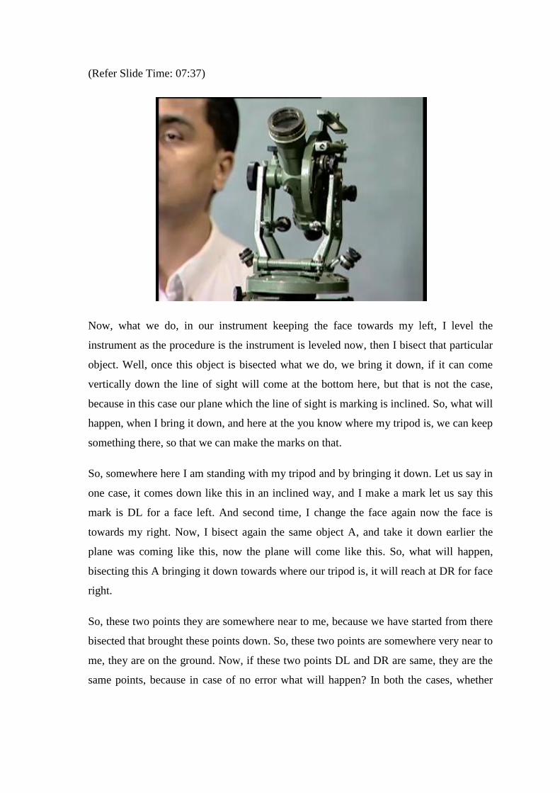
Now, what we do, in our instrument keeping the face towards my left, I level the
instrument as the procedure is the instrument is leveled now, then I bisect that particular
object. Well, once this object is bisected what we do, we bring it down, if it can come
vertically down the line of sight will come at the bottom here, but that is not the case,
because in this case our plane which the line of sight is marking is inclined. So, what will
happen, when I bring it down, and here at the you know where my tripod is, we can keep
something there, so that we can make the marks on that.
So, somewhere here I am standing with my tripod and by bringing it down. Let us say in
one case, it comes down like this in an inclined way, and I make a mark let us say this
mark is DL for a face left. And second time, I change the face again now the face is
towards my right. Now, I bisect again the same object A, and take it down earlier the
plane was coming like this, now the plane will come like this. So, what will happen,
bisecting this A bringing it down towards where our tripod is, it will reach at DR for face
right.
So, these two points they are somewhere near to me, because we have started from there
bisected that brought these points down. So, these two points are somewhere very near to
me, they are on the ground. Now, if these two points DL and DR are same, they are the
same points, because in case of no error what will happen? In both the cases, whether

face left or face right, in both the cases the vertical plane or the line of sight will reach
here which is point D, but if the error is there they will reach at DL and DR.
So, this is a test, by carrying out this test we can know yes there is error in the
instrument, because of non perpendicularity of the horizontal axis from the vertical axis,
now how to eliminate it permanently how to adjust it. So, this permanent adjustment of
the instrument what we do in this case? We find this middle point, because we know the
point DL, we know the point DR, and there on the ground I can locate this middle point
now. Having located this middle point, I will bisect now after rotating my theodolite, I
will bisect the point there on the ground, that particular point is bisected.
Then I raise it up, when I raise it up where will I go, I might go naturally somewhere like
this. So, starting from this point D I should have reached A, if there was no problem, but
because, there is a problem that is why I reached here. Now, at this stage, once I am this
far from A what we do? In our instrument in all the instrument this facility is there, I can
change the orientation of horizontal axis, how we have the capstans screws here, I can
use this capstans screw, and by using this capstans screw, we can change the orientation
of the horizontal axis.
So, depending where I need to bring, I need to take this point to A. So, I will start using
my screw here in order to bring this point to A. So, once this point is at A, my instrument
is adjusted. I have corrected my horizontal axis, I made it perpendicular. Well, this thing
needs to be done in trial and error, because just in one operation you may not converge.
So, by trial and error we keep doing it till this error is fully eliminated. And in a spire test
we find whether we are doing it from face left or face right we are always reaching at
this point.
Okay, the another error which may be there is, because line of sight is not perpendicular
to horizontal axis. Let us think about it what is the meaning of this? And why it may
happen. Somewhere here, if you visualize the theodolite somewhere here, this is the
eyepiece over here is the plane of the cross wire which we say diaphragm. Now, this
plane of the cross wire or the center of the cross wire, when we join the center of the
cross wire to the centre of the objective lens, it may reach the line of sight. Because, we
use that line in order to bisect the objects in order to define where my line sight is, now it
might happen as we can see here.
(Refer Slide Time: 12:44)
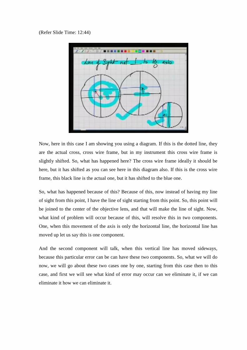
Now, here in this case I am showing you using a diagram. If this is the dotted line, they
are the actual cross, cross wire frame, but in my instrument this cross wire frame is
slightly shifted. So, what has happened here? The cross wire frame ideally it should be
here, but it has shifted as you can see here in this diagram also. If this is the cross wire
frame, this black line is the actual one, but it has shifted to the blue one.
So, what has happened because of this? Because of this, now instead of having my line
of sight from this point, I have the line of sight starting from this point. So, this point will
be joined to the center of the objective lens, and that will make the line of sight. Now,
what kind of problem will occur because of this, will resolve this in two components.
One, when this movement of the axis is only the horizontal line, the horizontal line has
moved up let us say this is one component.
And the second component will talk, when this vertical line has moved sideways,
because this particular error can be can have these two components. So, what we will do
now, we will go about these two cases one by one, starting from this case then to this
case, and first we will see what kind of error may occur can we eliminate it, if we can
eliminate it how we can eliminate it.

(Refer Slide Time: 14:22)
The first error now, it is because of the movement of horizontal here, the horizontal here
has shifted here from its original position. So, the point of the cross wire or this point
about which we define the line of sight is now this point. Now, what will happen? If you
see this in the instrument the cross wire is like this, now it has shifted up. Of course, I am
magnifying this error, it is not that much inside the instrument, but in order to understand
it I am just trying to magnify it.
Ideally, it should be at the centre, but we are taking it up, because of the error. So, what
will happen, then now the line of sight is from this point which is the center of the cross
wire, and the center of the objective, so the line of sight is inclined. Well, let us say the
effect of this, this is my telescope. So, the line of sight is now, that is the center of the
objective lens it is inclined, it is not horizontal. In ideal case, in case of the horizontal
line it should have been like this. Now, if it is so what will be the problem?
Well, the problem will be if I am measuring a vertical angle, in case of the vertical angle
what we do. We make this reading 0, 0, 0 and we consider the line to be horizontal, and
then we start taking the observation from there I take it up and measure the angle. But,
now when I am taking it up, I am not starting my measurement from the horizontal line,
rather I am starting my measurement, because I am looking down from the horizontal
line.
Because, right now the center of the cross wires if it is here, let us say I have exaggerated
it, if it is here the line of sight is inclined. So, we are initially bisecting somewhere there,
and then in order to take it up, I have to rotate my telescope more than the actual angle.
So, the effect of that is the vertical angle that we observe here is different than the actual
vertical angle, so this is an error. Now, how can we eliminate it, to eliminate it now we
will see here in the instrument itself, what we do?
Let us say, right now the cross wire is here of the center of the cross wire is here, the face
is towards my right. Now, change the face, in changing the face just follow me where I
am holding is the center of the cross wire. Well, to change the face, it will stay like this,
it will stay like this, and that is the centre of the cross wire, and the center of the cross
wire comes down. Well, now the face has changed, but in order for me to observe I will
rotate it like this, and now the cross wire center is here and here.
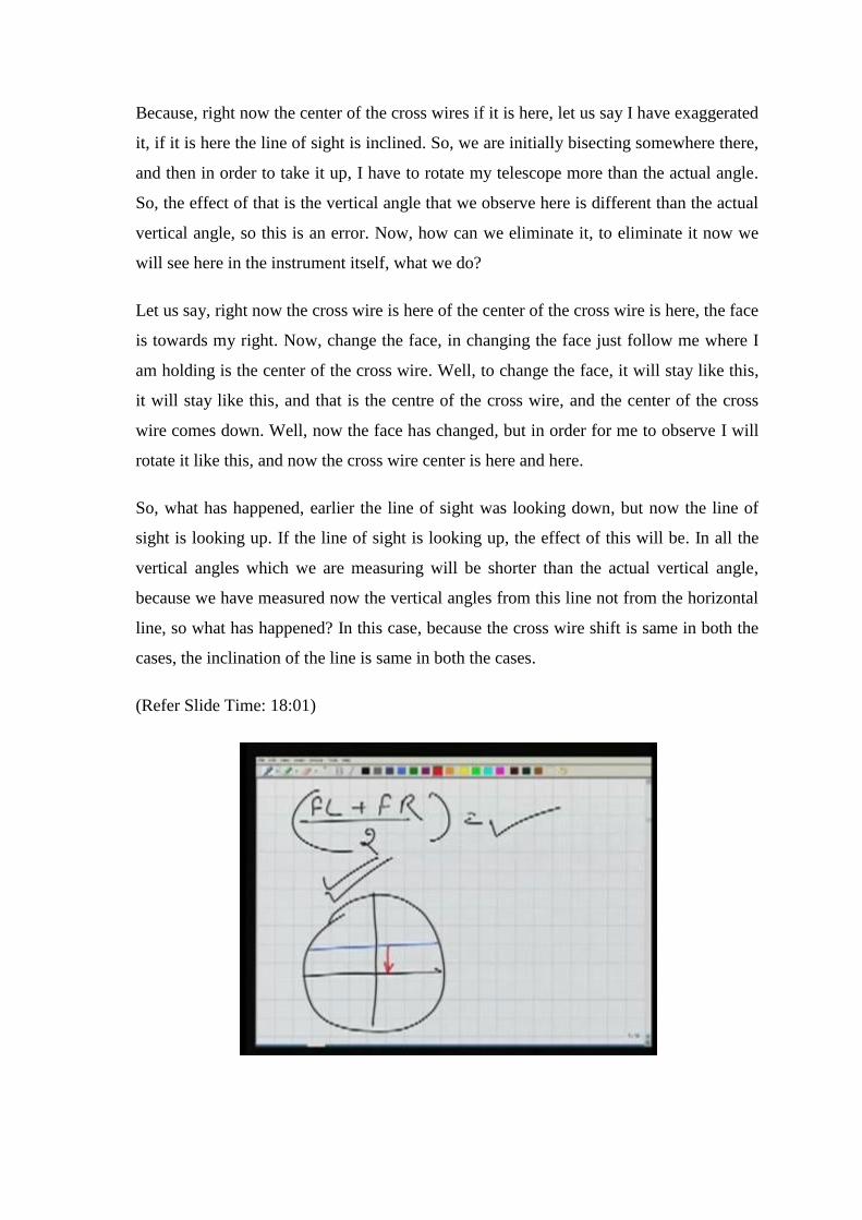
So, what has happened, earlier the line of sight was looking down, but now the line of
sight is looking up. If the line of sight is looking up, the effect of this will be. In all the
vertical angles which we are measuring will be shorter than the actual vertical angle,
because we have measured now the vertical angles from this line not from the horizontal
line, so what has happened? In this case, because the cross wire shift is same in both the
cases, the inclination of the line is same in both the cases.
(Refer Slide Time: 18:01)

So, if we are taking face left observation and face right observation, and we take the
mean of that we will get the correct value, because the error is being eliminated. In one
case the error was positive, because we are measuring more angles. In the second case
the error is negative, because we are measuring less angle. So, we can combine these two
readings like this here, so the error can be eliminated. So, yes if at all this kind of
problem is there shift of horizontal wire, it can be eliminated by taking face left and face
right observations, and the vertical angles can still be measured correctly.
However, can we adjust it also can we permanently change this. The meaning of
adjustment is now as we know our horizontal here has shifted here. We want to bring it
down, we want to pull it down, so that it is at its original position, it had shifted up, so
we want to bring it down. So, what is the procedure for this, the procedure for this is
what we are going to do now.
(Refer Slide Time: 19:21)
So, the procedure is we go to the ground where we have a level ground, and at a distance
of around 75 meter to 100 meter larger the distance, better will be the result. We keep a
ranging rod this is either a ranging rod or a staff. We will see later on what a staff is?
Staff is basically a vertical ruler; it is a rod which has the graduations also. So, we can
keep that staff here or ranging rod then we keep our theodolite here.
Now, in our theodolite we keep let us say face left, as the face in the theodolite for me is
left now. Then what we do, we set our theodolite to any particular angle value. Let us say

I set my theodolite to 0, 0, 0 how do we do it? We will rotate it till the readings over here
in these two vernier C and D are 0, 0, 0. Well the readings are 0, 0, 0 now. Then I bisect
the ranging rod, so the ranging rod is bisected here at A. Now, why I am taking it this
way, because we know there is a shift, and if this shift is right now the center of the cross
wire is somewhere here. So, the line of sight is going up.
Well, I am bisecting the ranging rod at A, then I change the face, because the line of
sight is here, now the line of sight will come here at the center of the cross wire, and then
it will stay here line of sight will go down now. So, if it goes down what we do, we
change the face, we set the same angle value here, what we have set previously let us say
0, 0, 0. And then we take another line of sight, and you bisect it on the staff or ranging
rod.
Well, the test is if the readings of A and B are same, if points A and B are same there is
no error. But, if these two are not same there is error in the instrument, because of shift
of the horizontal here, how to correct it? To correct it, there in the rod or the ranging rod
we mark the center point. Let us say the center point is C. Now, we have marked the
center point on this, then what we do? We know this particular error is because of shift
of the horizontal here. In ideal case, the horizontal here should have bisected the point C,
but it is not bisecting it, so what we do now.
We have in our instrument, again some facility, which are called capstan screws by
which we can move the diaphragm up and down. So, the entire diaphragm, because the
cross wires have shifted like this. I want to move this entire diaphragm up and down. So,
this entire diaphragm can be moved up and down, and by moving it. Let us say right
now, we have bisecting B, but we want to bisect C, I move the diaphragm here at the
theodolite, so that I bisect now C.

(Refer Slide Time: 22:36)
So, what is happening, I am basically moving my cross this blue line to its original
position. So, this entire diaphragm, because when you look to the cross wire there will
not be two lines like this, there will be only a thing like this. So, we are bringing it down,
and after bringing it down it will reach to its original position. Again, this thing needs to
be done you know by trial and error. Now, for trial and error you know time and again
you keep you need to repeat it. So, keep repeating it till you find that your test is
satisfied. Now, we are going to look at the other aspect.
(Refer Slide Time: 23:13)

Well, here we are talking of the error due to vertical hair movement. Now, this vertical
hair as you can see here, it has shifted to this position. So, how the cross wire may look
like, it may look like this. Of course, I am exaggerating these errors here, so that we can
understand using these figures. It will not be that big amount of error in the instrument,
but to understand it I am exaggerating it. So, the cross wire may look like this. Now, the
line of sight is again, this particular point here and the center of the objective.
Now, start visualizing that line in the instrument. Here in the instrument the cross wire
has shifted this way, sideways. So, this vertical hair has shifted this way, in ideal case it
should have been at the center. And the center point of the cross wire joining to the
center of the objective that should have been the line of sight. But, now what is happened
to the line of sight, this point has if I do it for you, it has shifted sideways. So, now the
center of the cross wires is here where I am holding it. If the center of the cross wire is
here, and you are looking through this line, center of the cross wire and the center of the
objective, what will happen.
Well, in this case let us say that is the point where the center of the cross wires is
somewhere here, ideally it should have been here. Now, certain thing you have to
visualize it. If I rotate my telescope now what will happen, what the line of sight will
make, I am rotating my telescope like this, what will be formed by the line of sight? If
you think it now the line of sight, because I am holding the cross wire is here, and this is
the line of sight going this way.
So, if you rotate it this way all through the line cross wire is here of the way. So, line of
sight will form a cone in this case, a cone like this. In earlier case, we saw the line of
sight will form an inclined plane not a vertical plane. In this case, it is not forming a
vertical plane rather it is forming a cone, a cone which is centered here and something
like this.

(Refer Slide Time: 25:48)
Now, that is the problem, if that is the problem what will happen, if you are taking the
observations as in earlier case, there is one object A, another at B at different heights,
and somewhere here is the observer. And I want to measure the angle between A and B
the horizontal angle between A and B from this position what I do, I bisect first A in the
instrument I have bisected A, now I bring it down. So, in ideal case, while I bring it
down I should have brought it down along the horizontal vertical line, but this is not the
case here what is happening, I am bringing it down as per the cone somewhere here.
Then it is starting from this point, I rotate my line of sight or my telescope, so is to reach
here B, I bisect B. And I measure the angle let us say, alpha plus some error here,
because the alpha is in case of the actual line of sight, the actual line of sight not actual,
but without if there is no error. If there is no error A will come down to its projection at
this point from here, we can measure the angle which is alpha, but with the error. A is
brought down here at A dash, and from A dash I measure the angle which is alpha plus
some error value.
So, if you are taking the observations only on single face, our observations will be
wrong. Well, now if I change the face, start thinking we had our cross wire had shifted
here. So, this is the point where the cross wires is. Now, I am going to change the face,
right now the face is right for me, and in face right that is the point A dash which we are

getting here, then now I change the face what is the procedure. Well, I transit it this is
where the cross wire will be now.
Well, that is the cross wire, then I rotate it this is where the cross wire is I am holding it
here center of the cross wire, and I take it like this. Now, as you can see, by changing the
face the cross wire has shifted, the center of the cross wire has shifted from here to there.
So, earlier now if I rotate my line of sight what will happen, earlier the cone was being
formed in that direction, now the cone will be formed in this direction. Well, if in this
case, now I bisect A bring it down. So, the meaning is I bisect A bring it down. So, it will
come here and then I measure my angle.
So, measuring angle means after bring it down, I rotate my line of sight, bisect B and I
measure the angle. So, this angle will be again this error will be e. Let us say this angle,
which I measured is alpha minus e, in this case I had measured alpha plus B, alpha plus
e. So, what we see, if you can take again here face left plus face right observations, and
their mean this error can be eliminated, because in one case the error is positive, in other
case it is negative.
Because, here in this case it is increasing the angle value, here in this case it is decreasing
the angle value. So, we are summing these two up. So, they will compensate. So, this is
another example of principle of reversal by using this principle of reversal, reversal
means face left and face right, we can eliminate this error.
(Refer Slide Time: 29:39)

Well, how we can eliminate this error permanently, is there any method, so that we can
eliminate this permanently from our observations or from our instrument. Permanent
means we need to bring, now the cross wire is here that is the cross wire it has shifted.
So, I need to bring it to the center. So, to bring it to the center, what I need to do, how
should I bring it to the center? Of course, there is a possibility here I can move my
diaphragm this way using the capstans screws, I can move my diaphragm. But, by what
amount should I move my diaphragm we should know this, so how to do this, we have
got one more test for that, and this is very interesting test.
Let us say in this test what we do? We put our theodolite at a point O, where I am
standing right now. Then let us say, on one side we take a length of 100 meter, similarly
on this side also this length should be 100 meter, larger this length better will be the test,
as well as the adjustment. So, around 100 meter and 100 meter lengths we take. We keep
a ranging rod here, thus ranging rod is let us say A, what we do now, well what we have
done. We have kept a ranging rod, 100 meters away from this theodolite, it is there
somewhere.
Now, we level the instrument all these leveling other things are done with the instrument,
I now bisect that ranging rod. So, this ranging rod here is bisected while the instrument is
here. Let us say, we start from the ideal case there is no error in the instrument, because
of this shifting of the cross wire, the cross wire is here only in the center. If it is in the
center it will form a vertical plane, while I am rotating the line of sight it will mark a
vertical plane.
So, the situation in that case is: if I bisect A, then I transit it back, the transiting means
that is transiting. And earlier, I am bisecting now A, so I am seeing through the cross
eyepiece, now A is bisected then I transit it, it is transited. Then I move here, I use I
again see through the eyepiece and in this direction. So, in this direction I set another
ranging rod B, because I can bisect it I can see through the eyepiece, and I can bisect that
ranging rod. And I say that is the point where the ranging rod is now, I put this ranging
rod.
Then what we do next, we change the face, well now the face is changed again A is
bisected. And again we transit it, and looking from here if the A is bisected after
changing the face, and there is no error in the instrument. Second time also what will
happen, you will automatically bisect B which was established earlier. But, if there is
error then what will happen.
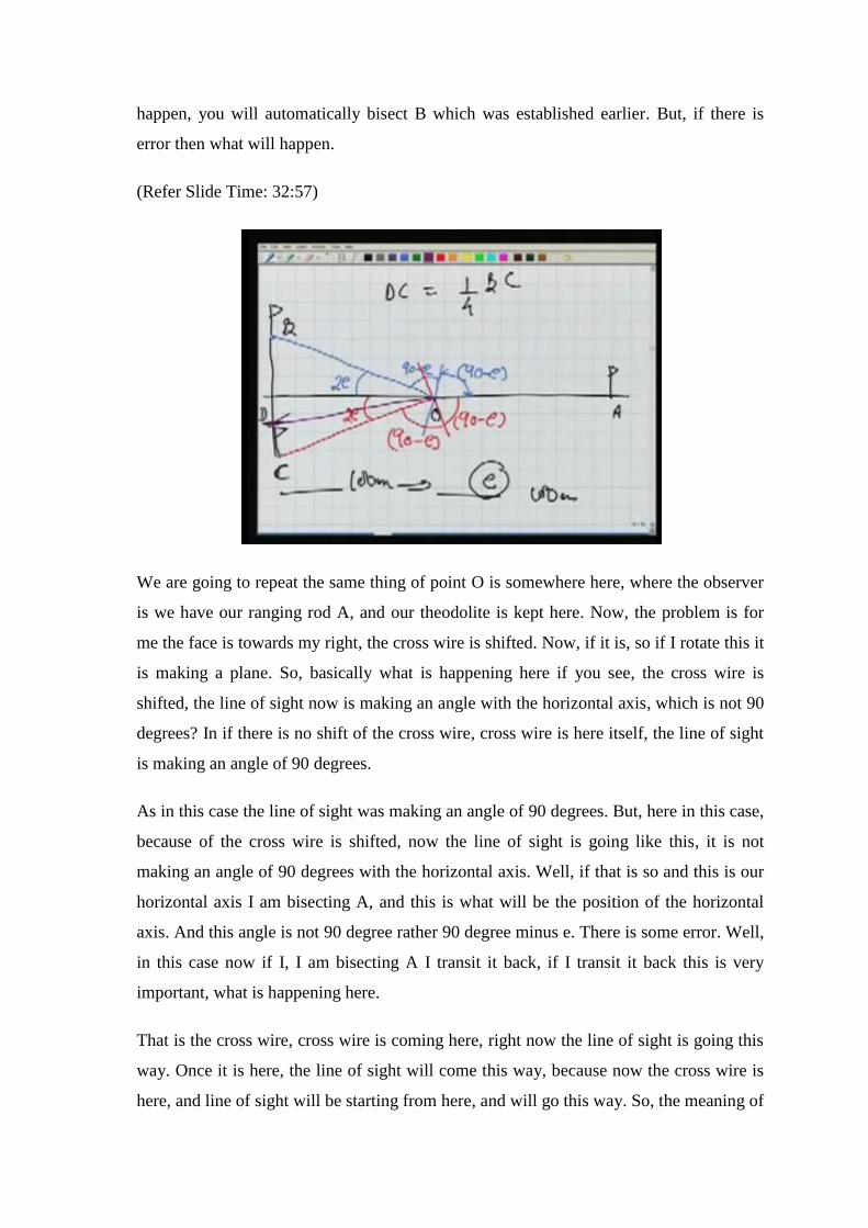
(Refer Slide Time: 32:57)
We are going to repeat the same thing of point O is somewhere here, where the observer
is we have our ranging rod A, and our theodolite is kept here. Now, the problem is for
me the face is towards my right, the cross wire is shifted. Now, if it is, so if I rotate this it
is making a plane. So, basically what is happening here if you see, the cross wire is
shifted, the line of sight now is making an angle with the horizontal axis, which is not 90
degrees? In if there is no shift of the cross wire, cross wire is here itself, the line of sight
is making an angle of 90 degrees.
As in this case the line of sight was making an angle of 90 degrees. But, here in this case,
because of the cross wire is shifted, now the line of sight is going like this, it is not
making an angle of 90 degrees with the horizontal axis. Well, if that is so and this is our
horizontal axis I am bisecting A, and this is what will be the position of the horizontal
axis. And this angle is not 90 degree rather 90 degree minus e. There is some error. Well,
in this case now if I, I am bisecting A I transit it back, if I transit it back this is very
important, what is happening here.
That is the cross wire, cross wire is coming here, right now the line of sight is going this
way. Once it is here, the line of sight will come this way, because now the cross wire is
here, and line of sight will be starting from here, and will go this way. So, the meaning of

that is, now the line of sight will be again it will make 90 minus e angle, because the
angle will remain same. And this is how the line of sight will go. So, what we are doing.
We have bisected A, transiting it and we are establishing one more ranging rod here.
Let us say that ranging rod we say B as in the earlier case. Now, what we do, we change
the face, well the face is changed. The cross wire was earlier here, and now the cross
wire, because it moves from here along with this another cross wire is shifted here,
earlier it was here, now it has shifted here the face is left. Now, again in this face left
what will happen, if I bisect A the next position of my horizontal axis will be like this.
Then only I can bisect A, because this angle will be 90 minus e. Then I transit it back as
in the previous case by transiting back, I will be looking in this direction and this angle
will be again 90 minus e, obviously.
Now, what this value will be this angle will be here, you can compute it easily two e.
Similarly, this is also two e, well what we have done. We have again we are establishing
a ranging rod at C. So, this is the test, if point B and C are same there is no error.
Otherwise, there is error in the instrument, because of shift of the vertical here, how to
eliminate it, what is the error, the error in the instrument is only e. So, what we do, we
join these two points, this is around 100 meter here, similarly 100 meter here.
So, we join these two points, and we find a point here which is one fourth of this total
distance BC. So, let us say this point is D. So, DC is 1 by 4 of BC. So, in ideal case how
much I should move my cross wire. I should move my cross wire, because now in my
cross wire is somewhere here, and I should move my cross wire, so that I start bisecting
D. Well, this what we do, we release the capstan screw, we move the cross wire now in
order to bisect this D. So, the D is bisected, let us say the D is bisected.
So, when we are doing it, what we are doing, we are bringing the vertical cross wire to
its actual position or its true position. So, this is how, we can adjust the instrument for
this error. Again in this case also we need to repeat this procedure, because just in one
single go we will not reach the answer.

(Refer Slide Time: 38:05)
Now, we will see another error, and this error is called index error, what is an index
error. If our vertical circle reading is 0, and our altitude bubble is in center. In that case,
the line of sight should be horizontal, obviously. Because when our line of sight is
horizontal, our reading is 0, 0. So, that makes our reference. If this is not true for 0
reading of the vertical circle, and altitude bubble in center if this is not horizontal what
will happen? We are measuring now vertical angles not from the horizontal reference,
the other form some other reference. So, if this is the problem in the instrument. Then
what will be the effect, it will start introducing, some error in our vertical angle
measurement.

(Refer Slide Time: 39:07)
Well, this is the case this is the vertical circle here. And this frame is the frame of the
altitude bubble; the altitude bubble is in center, so this line is horizontal. In ideal case,
this blue line when the reading is 0 and 0 should be also horizontal. Now, let us say this
is not the case the line of sight is now inclined, because of some problem with the
instrument. We will come to that particular problem, where the problem lies and we will
see the effect of this also. So, what will be the effect of this, the effect is very obvious.
Well, my face is left the reading is 0, 0, altitude bubble is in center, I take the observation
the line of sight is going inclined, so I am measuring more value of angle. Next, I change
the face, now the line of sight will go up naturally we are changing the face. So, we will
measure the angle smaller angle for the same 0, 0, value here, and altitude bubble in
center.

(Refer Slide Time: 40:24)
So, it is very obvious that we can eliminate this index error also by taking face left and
face right observations and their mean. So, we can eliminate this index error also by
doing this. Now, we are going to see can we really adjust this also permanent adjustment
of this in our instrument. If it is so what is the procedure for this?
(Refer slide Time: 40:52)
So, the procedure for this permanent adjustment is, permanent adjustment of/for index
error. Now, the thing is same we keep you know around a 100 meter long line of sight
we take it, and we keep a staff here for a ranging rod. We keep our theodolite here, and

with this theodolite for what we do now? Number 1 step, we make first of all now in our
theodolite we will level it against using the plate bubble, and then we level it using the
altitude bubble, because this is more sensitive.
So, altitude bubble is in center now. Then by rotating this telescope, while looking
through this vernier C and D, I am making the readings here 0, 0, 0. Altitude bubble is in
center by rotating this telescope, while I rotate this telescope there is no problem with the
altitude bubble, because they are two different frames. So, I make the reading to be 0, 0,
0. Well, now altitude bubble is in centre, the reading is 0, 0, 0 and I can see through the
eye piece.
So, if I see through the eyepiece, I might bisect somewhere here which is point A. Then I
change the face, the face is changed. Again, because I have to bisect from here, altitude
bubble is in center, we make it to the center. And by rotating this telescope, I make the
same reading let us say the reading is made to be 0. Again now the reading is set to be 0.
So, as we have discussed if there is problem in the instrument, it will bisect somewhere
here. Now, how to eliminate this error, to eliminate this error what we do?
Again, we can locate the middle point here, which is C. And this is the point where we
should have bisected for altitude bubble to be in center, reading to be 0, 0, this line of
sight should be horizontal. And the line of sight which is horizontal is this line, we
should have bisected here. So, what is the procedure to correct it before the test, whether
A is equal to B or not that was the test, now the procedure to permanently adjust it.
Well the procedure is, once we have found this point C on the ranging rod or on the staff.
Now, I change it, let us say I right now I am bisecting B. I had already bisected A, and
this is how we could locate C. So, now from this telescope, we rotate the line of sight a
little we might use the capstan screw, because this will be very fine rotations. So, I use
the capstan screw here the tangent screw, I use the tangent screw I rotate the line of sight.
So, that this line of sight reaches C. So, now the cross wire is bisecting the point C.
Well, at this stage the line of sight is horizontal or we can say the telescope is horizontal,
is the reading in verniers 0, 0 now. It is not, because the reading was set about 0, 0
earlier, the reading was at 0, 0, when the point B was bisected. Now, we have rotated the
telescope along with the rotation of the telescope this vertical circle also rotates. And the
verniers are there where they were, so there is no change in the vernier position. So,
because of this rotation of the vertical circle, the reading is changed, well the reading is
different now. So, what we do, we make this reading 0, 0 now, how to make the reading
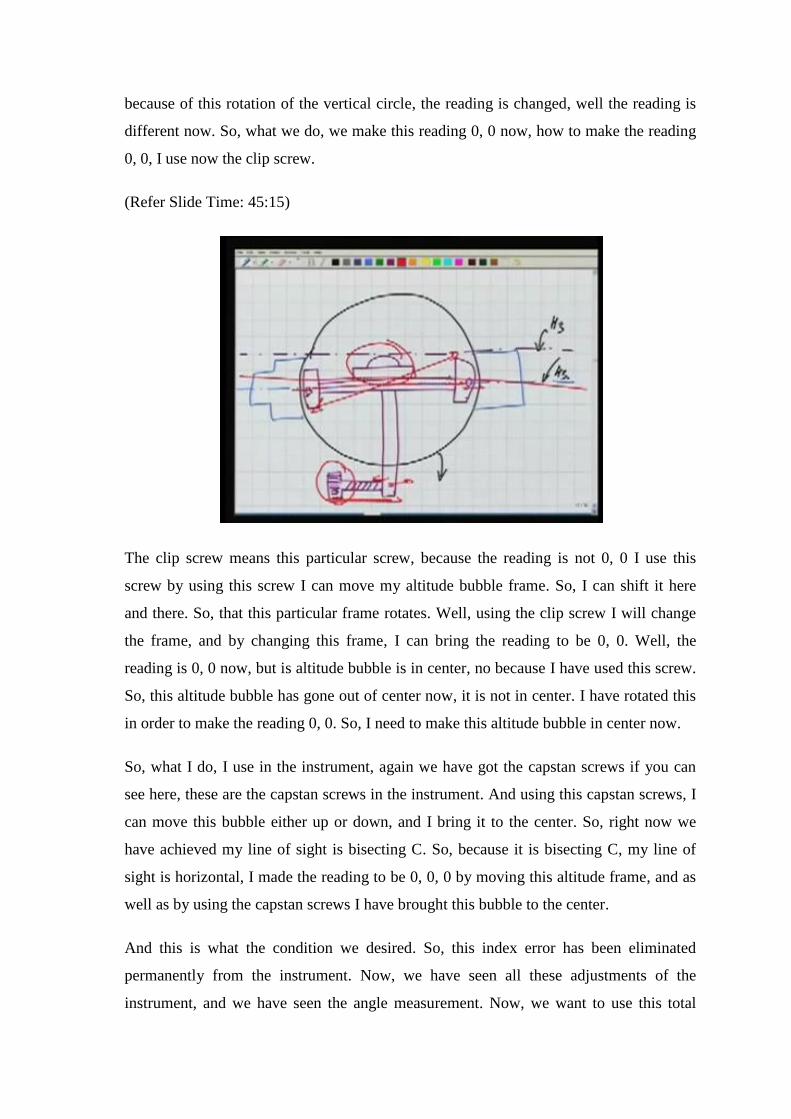
0, 0, I use now the clip screw.
(Refer Slide Time: 45:15)
The clip screw means this particular screw, because the reading is not 0, 0 I use this
screw by using this screw I can move my altitude bubble frame. So, I can shift it here
and there. So, that this particular frame rotates. Well, using the clip screw I will change
the frame, and by changing this frame, I can bring the reading to be 0, 0. Well, the
reading is 0, 0 now, but is altitude bubble is in center, no because I have used this screw.
So, this altitude bubble has gone out of center now, it is not in center. I have rotated this
in order to make the reading 0, 0. So, I need to make this altitude bubble in center now.
So, what I do, I use in the instrument, again we have got the capstan screws if you can
see here, these are the capstan screws in the instrument. And using this capstan screws, I
can move this bubble either up or down, and I bring it to the center. So, right now we
have achieved my line of sight is bisecting C. So, because it is bisecting C, my line of
sight is horizontal, I made the reading to be 0, 0, 0 by moving this altitude frame, and as
well as by using the capstan screws I have brought this bubble to the center.
And this is what the condition we desired. So, this index error has been eliminated
permanently from the instrument. Now, we have seen all these adjustments of the
instrument, and we have seen the angle measurement. Now, we want to use this total

stations or the theodolite. In our next video lecture, we will see the total station it is
various parts, but it will not be much different than the theodolite the basic concepts are
same.
(Refer Slide Time: 47:11)
Well, we want to use it for some application, and the application is we said theodolite
traverse. We want to carry out a traverse using the theodolite, why traverse we have
already answered this question when we were talking about the compass. Traverse has
many advantages you know it we can do the traversing anywhere. There is no restriction
as far as the visibility and all those things are concerned. We can have the shorter lines,
longer lines, different kinds of angles.
So, we can follow the road line, we can follow the river, all these things are possible in
the case of the traversing, the computations are stronger. So, traverse is supposed to be a
very good mode of doing the control survey. So, we can generate the control survey. So,
when I say control survey mean, I mean the skeleton of that ground, we can do it by
traversing. Now, what is theodolite traverse, why especially we want to say theodolite
traverse. It is same as compass traverse the only difference is here in this case, these
angles are being measured by a theodolite.
Now, theodolite is very precise instrument. We have the precision of 1 second, 5
seconds, 20 seconds. So, we need equally precise linear measurement instrument. So,

now, EDM is available. So, we can use EDM for measurement of these lines, while these
angles are being measured by the theodolite, and we have our theodolite traverse.
(Refer Slide Time: 48:44)
Now, what are the types of the traverse? Again we have seen this, a traverse may be
closed, the closed means here is the closed traverse. It starts from a point and finally
reaches there only. So, the same thing we started taking the observations in the ground
from one point we did the traversing, again reached the point. So, this is closed traverse
or the loop traverse, also it is called polygonal, then the other traverse is open traverse.
Open means, we start from a point keep following a road or any other object, but do not
reach the original point. So, it is open.
Then we have another one which we say link. In the case of the link, it looks like open
traverse except the starting line and the closing line are known to us. I am writing right
now, known these two lines are known. Known means these two lines had been done
using some more accurate survey. Similarly, this line they had been done using very,
very accurate survey. Now, we have starting our this traverse by connecting over this
open traverse with these links, we will see the advantage of this in a moment.

(Refer Slide Time: 50:13)
Now, how to check the accuracy in a traverse, if it is a loop traverse, one method which
we know is we can sum up all the internal angles. For all these internal angles, we can
find their sum, and we can check whether the sum is equal to this (2 n minus 4 into 90),
where n is number of the sights. If it is, so we are sure that well the internal angles which
had been measured or done correctly. But, this is not the full solution, why it is not full
solution, because we have not done anything so far.
For length, while we are measuring the length of these lines, this length was measured,
this length was measured, and this length, this length, and this length. So, in measuring
these lengths also some errors were introduced, we cannot measure the true value. So,
this particular check here, the check, this check does not take care of the length as we
have seen in case of the compass traverse also. In our case of compass traverse, we had
adjusted our angles for this correction, but still we found, because of the error in length
our compass traverse will not close. So, the same thing will happen here for this length,
and some similarly for the orientation.

(Refer Slide Time: 51:39)
Now, what is the meaning of this? The length means if you do a traverse in the ground,
we have corrected for the internal angles, and then we plot it. The plotting of the traverse
may look like this, but with closing error, because the land had not been adjusted.
(Refer Slide Time: 52:00)
Similarly, the error of orientation, orientation means there in the ground or traverse is
oriented this way. Let us say this is the mean orientation of the traverse, once we plot it
we might plot it this way. So, there is an orientation error, how to eliminate this
orientation error. We need to take bearing of the lines also, let us say if I had measured

the bearing of this line, from the north, whatever this value theta is and then I would have
ensured that the same bearing of this line AB. AB here is ensured, because these two
bearings are not same. So, by measuring this bearing and using that while we are plotting
we can eliminate this orientation error.
(Refer Slide Time: 52:50)
Well, we go further in the case of the link traverse. In the case of the link traverse, how
we can do the accuracy check. Now, this is a thing the purpose why we want to connect
our open traverse to 2 lines, which are known as I said earlier. These two lines are done
by some previous survey, and are very accurately done this is our high order survey. We
are connecting our open traverse here with these two lines, how can make use of these in
order to adjust the errors in our open traverse.
Well, I know the bearing of this line, and then I am measuring the bearing of all these
lines. So, for example, let us say I am measuring all these lengths, all these angles, all
these lengths and so on. So, starting from this known line, and these all angles, the angle
here, the angle here, and as well as all the lengths, what I can do is starting from this
known line, I can compute the bearing of this line, because it is a simple computation.
So, I can compute the bearing of this line which will be this angle. If there is error in
between which will be there?
The bearing which we are computing here will not be the bearing of this line actually
there in the ground. So, what we find, we find there is error in between, because we

started from a known line, we are reaching unknown line. And a starting from this
known line, we use then later on all the measurements which we had done in the field for
our open traverse. And using those measurements we computed the bearing of this line,
and the bearing is not coming same, so there is error in between here. So, what we can do
by finding this amount of the error e, we can adjust our angles accordingly.
(Refer Slide Time: 55:05)
So, this adjustment procedure could be let us say if this is our link traverse, and it does
not close here, as well as it computes the bearing wrongly. Let us say we I am taking the
case that it does not close here. Closing means, I had done a traverse in the field, and
now I am plotting it here. And by plotting it here using these angles and the lengths, I
find that it does not close. So, what we want to do, we want to apply correction to it. I
want to take it here to the known position. So, each and every line will be shifted
accordingly, so that it reaches here. So, what we are doing, we are applying correction to
our observed values, so that we are adjusting for the errors. So, we can make use of these
known lines in the link traverse for adjusting our open traverse.

(Refer Slide Time: 56:07)
Well, going back now, in case of the open traverse is there any way we can apply the
check? No there is no control on this open traverse. So, we cannot apply a check. So,
because of this purpose generally the open traverse are not preferred. We should try to do
some kind of checks there even if we need to do the open traverse, we can do some
intermediate checks. For example, I am observing this open traverse, but I take also this
measurement, and you know some measurement. So, I measure this length. So, I can
make use of this length in order to apply checks in this part of the traverse. So, generally
in the open traverse there is no method to apply the checks, unless we go for check lines
like this, some extra measurements.
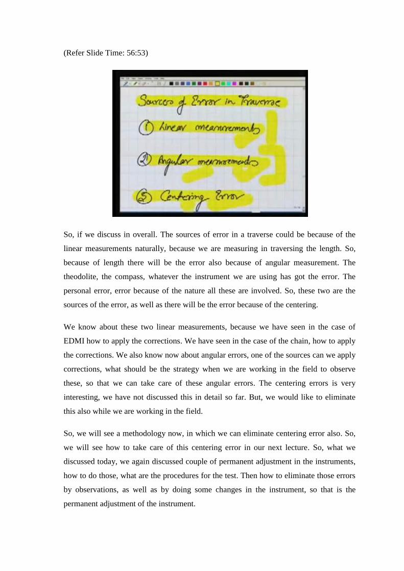
(Refer Slide Time: 56:53)
So, if we discuss in overall. The sources of error in a traverse could be because of the
linear measurements naturally, because we are measuring in traversing the length. So,
because of length there will be the error also because of angular measurement. The
theodolite, the compass, whatever the instrument we are using has got the error. The
personal error, error because of the nature all these are involved. So, these two are the
sources of the error, as well as there will be the error because of the centering.
We know about these two linear measurements, because we have seen in the case of
EDMI how to apply the corrections. We have seen in the case of the chain, how to apply
the corrections. We also know now about angular errors, one of the sources can we apply
corrections, what should be the strategy when we are working in the field to observe
these, so that we can take care of these angular errors. The centering errors is very
interesting, we have not discussed this in detail so far. But, we would like to eliminate
this also while we are working in the field.
So, we will see a methodology now, in which we can eliminate centering error also. So,
we will see how to take care of this centering error in our next lecture. So, what we
discussed today, we again discussed couple of permanent adjustment in the instruments,
how to do those, what are the procedures for the test. Then how to eliminate those errors
by observations, as well as by doing some changes in the instrument, so that is the
permanent adjustment of the instrument.


![[XLS] · Web viewSatyal KAMSED05253761 KAMTHA02123240 KAMADH11300106 Kamala Adhikari lohani KAMBHA07222305 KAMDAN09176488 Dangal KAMGHA12267353 Ghale KAMGHI10018916 KAMTHA03177194](https://img.dokumen.tips/doc/110x75/5b34e26a7f8b9aec518ca571/xls-web-viewsatyal-kamsed05253761-kamtha02123240-kamadh11300106-kamala-adhikari.jpg)