Embed Size (px)
Citation preview
HAL Id: hal-02182827https://hal.archives-ouvertes.fr/hal-02182827
Submitted on 13 Jul 2019
HAL is a multi-disciplinary open accessarchive for the deposit and dissemination of sci-entific research documents, whether they are pub-lished or not. The documents may come fromteaching and research institutions in France orabroad, or from public or private research centers.
L’archive ouverte pluridisciplinaire HAL, estdestinée au dépôt et à la diffusion de documentsscientifiques de niveau recherche, publiés ou non,émanant des établissements d’enseignement et derecherche français ou étrangers, des laboratoirespublics ou privés.
Survey on hardware implementation of random numbergenerators on FPGA: Theory and experimental analyses
Mohammed Bakiri, Christophe Guyeux, Jean Couchot, Abdelkrim Oudjida
To cite this version:Mohammed Bakiri, Christophe Guyeux, Jean Couchot, Abdelkrim Oudjida. Survey on hardware im-plementation of random number generators on FPGA: Theory and experimental analyses. ComputerScience Review, Elsevier, 2018, 27, pp.135 - 153. �hal-02182827�
Survey on Hardware Implementation of RandomNumber Generators on FPGA: Theory and
Experimental Analyses
Mohammed Bakiria,b,∗, Christophe Guyeuxa, Jean-Francois Couchota,Abdelkrim Kamel Oudjidab
aFemto-ST Institute, DISC Department, UMR 6174 CNRS, University of BourgogneFranche-Comte, Belfort, 90010, France
bCentre de Developpement des Technologies Avancees, ASM/DMN Department, Cit 20 aot1956 Baba Hassen, B. P 17,16303, Alger, Algeria
Abstract
Random number generation refers to many applications such as simulation, nu-
merical analysis, cryptography etc. Field Programmable Gate Array (FPGA)
are reconfigurable hardware systems, which allow rapid prototyping. This re-
search work is the first comprehensive survey on how random number generators
are implemented on Field Programmable Gate Arrays (FPGAs). A rich and up-
to-date list of generators specifically mapped to FPGA are presented with deep
technical details on their definitions and implementations. A classification of
these generators is presented, which encompasses linear and nonlinear (chaotic)
pseudo and truly random number generators. A statistical comparison through
standard batteries of tests, as well as implementation comparison based on speed
and area performances, are finally presented.
Keywords: Random Number Generators, Field-Programmable Gate Array,
Chaos, Physical security, Hardware Security, Applied Cryptography
∗Corresponding authorEmail addresses: [email protected] (Mohammed Bakiri), [email protected]
(Christophe Guyeux), [email protected] (Jean-Francois Couchot), [email protected](Abdelkrim Kamel Oudjida)
Preprint submitted to Journal of Computer Science Review February 3, 2018
1. Background and Motivation
Randomness is a common word used in many applications [1] such as sim-
ulations [2], numerical analysis [3], computer programming, cryptography [4],
decision making, sampling, etc. The general idea lying behind this generic word
most of the times refers to sequences, distribution, or uniform outputs gener-5
ated by a specific source of entropy. In other words, the probabilities to generate
the same output are equal (50% to have “0” or “1”). If we take the security
aspect, many cryptosystem algorithms rely on the generation of random num-
bers. These random numbers can serve for instance to produce large prime
numbers which are at the origin of cipher key construction [5] (for example, in10
RSA algorithm [6], in Memory Encryption [7] or Rabin signatures [8]). Further-
more, when the generators satisfy some very stringent properties of security, the
generated numbers can act as stream cyphers in symmetric crytosystems like
the one-time pad, proven cryptographically secure under some assumptions [9].
Randomization techniques are especially critical since these keys are usually15
updated for each exchanged message. Even if an adversary has partial knowl-
edge about the random generator, the behavior of this latter should remain
unpredictable to preserve the overall security.
From a historical point of view, numerical tables and physical devices have
provided the first sources of randomness designed for scientific applications. On20
the one hand, random numbers were extracted from numerical tables like census
reports [10], mathematical tables [11] (like logarithm or trigonometric tables,
of integrals and of transcendental functions, etc.), telephone directories, and
so on. On the other hand, random numbers were extracted also from some
kind of mechanical or physical computation like the first machine of Kendall25
and Babington-Smith [12], Ferranti Mark 1 computer system [13] that uses
the resistance noise as a physical entropy to implement the random number
instruction in the accumulator, the RAND Corporation [14] machine based on
an electronic roulette wheel, or ERNIE (Electronic Random Number Indicator
Equipment [15]), which was a famous random number machine based on the30
2

noise of neon tubes and used in Monte Carlo simulations [16, 17].
These techniques cannot satisfy today’s needs of randomness due to their
mechanical structure, size limitation when tables are used [11], and memory
space. Furthermore, it may be of importance to afford to reproduce exactly
the same “random sequence” given an initial condition (called a “seed”), for35
instance in numerical simulations that must be reproducible – but physical gen-
eration of randomness presented above does not allow such a reproducibility.
With the evolution of technologies leading to computer machines, researchers
start searching for low cost, efficient, and possibly reproducible Random Number
Generators (RNGs). This search historically began with John von Neumann,40
who presented a generation way based on some computer arithmetic operations.
Neumann generated numbers by extracting the middle digits from the square
of the previously generated number and by repeating this operation again and
again. This method called mid-square is periodic and terminates in a very short
cycle. Therefore, periodicity and deterministic outputs that use an operator or45
arithmetic functions are the main difference with the earlier generators. They
are known in literature as “pseudorandom” or “quasirandom” number genera-
tors (PRNGs), while circuits that use a physical source to produce randomness
are called “true” random number generators (TRNGs).
In most cases a random number generator algorithm can be defined by a50
tuple (S, f , g, U , x0), in which S is the state space of the generator, U is the
random output space, f : S → S is the transition mapping function, g : S → U
is the output extractor function from a given state, and x0 is the seed [18],
see Figure 1. The random output sequence is y1, y2, . . . , where each yt ∈ U
is generated by the two main steps described thereafter. The first step applies55
the transition function according to the recurrence xt+1 = f(xt), where f is
an algorithm in the PRNG case and a physical phenomenon in the TRNG one.
Then, the second step consists in applying the function generator to the new
internal state leeading to the output xt, that is, yt = g(xt). The period of
a PRNG is the minimum number of iterations needed to obtain twice a given60
output (a PRNG being deterministic, it always finishes to enter into a cycle).
3

Figure 1: General architecture of a random number generator
As stated previously, the old hardware manner to build such RNGs was to
use a mechanical machine or a physical phenomenon as entropy source, which
can thus be based on noise [19], metastability (frequency instability [20]), semi-
conductor commercial or industrial component circuit (PLL [21], amplifier, in-65
verter,. . . ), or a variation in the CMOS/MEMS process technologies (transis-
tor). In spite of the quality of the generated randomness, most of these tech-
niques are however, either slow processes (i.e, extracting noise from a compo-
nent) or costly (e.g., extracting or measuring noise may require specific equip-
ment like an oscilloscope). All these previous drawbacks are the motivation70
behind the development of hardware generators based on a software design.
The latter consist of developing deterministic algorithms by targeting a spe-
cific hardware system, like a Field Programmable Gate Array (FPGA), before
automatically deploying it on the hardware architecture by using ad hoc tools.
FPGA devices are reconfigurable hardware systems. They allow a rapid75
prototyping, i.e., explore a number of hardware solutions and select the best
one in a shorter time. The design methodology on FPGA relies on the use of a
High Description Language (i.e, Verilog, VHDL, or SystemC) and a synthesis
tool. Because of this, FPGA has become popular platforms for implementing
random generators or complete cryptographic schemes, due to the possibility to80
achieve high-speed and high-quality generation of random. The general archi-
tecture of a FPGA presented in Figure 2 is based on LCA (Logic Cell Array),
4
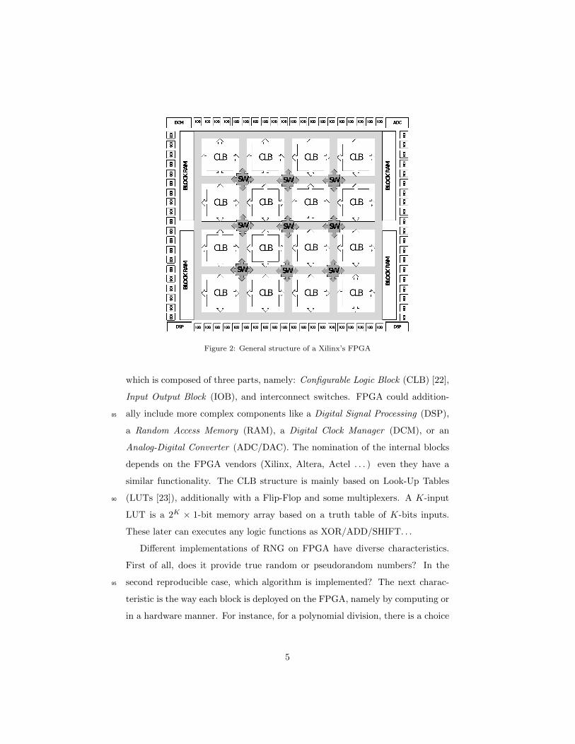
Figure 2: General structure of a Xilinx’s FPGA
which is composed of three parts, namely: Configurable Logic Block (CLB) [22],
Input Output Block (IOB), and interconnect switches. FPGA could addition-
ally include more complex components like a Digital Signal Processing (DSP),85
a Random Access Memory (RAM), a Digital Clock Manager (DCM), or an
Analog-Digital Converter (ADC/DAC). The nomination of the internal blocks
depends on the FPGA vendors (Xilinx, Altera, Actel . . . ) even they have a
similar functionality. The CLB structure is mainly based on Look-Up Tables
(LUTs [23]), additionally with a Flip-Flop and some multiplexers. A K-input90
LUT is a 2K × 1-bit memory array based on a truth table of K-bits inputs.
These later can executes any logic functions as XOR/ADD/SHIFT. . .
Different implementations of RNG on FPGA have diverse characteristics.
First of all, does it provide true random or pseudorandom numbers? In the
second reproducible case, which algorithm is implemented? The next charac-95
teristic is the way each block is deployed on the FPGA, namely by computing or
in a hardware manner. For instance, for a polynomial division, there is a choice
5
between look-up table in software and a hardware shift register. Furthermore,
the quality of the FPGA model that implements a random number generator
can be evaluated according to many criteria. In a statistical perspective, the100
output has to be verified against some well-known test suite like the NIST [24],
DieHARD [25], or TestU01 [26] ones. From the hardware perspective, one ob-
jective is to provide the highest frequency per randomly generated bit with less
FPGA hardware resources (CLB, IOB, ...).
This article surveys a large set of selected hardware implementations of ran-105
dom number generators on FPGA. Both pseudorandom and true random gen-
erators are investigated, while linear and non-linear generators are discussed in
the PRNG case. Each approach is explained in details, and a discussion on
the choices of both implementations and generations are systematically given.
Performance with respect to frequency, area size, weaknesses, and statistical110
evaluations are finally presented, when they are available.
The remainder of the article is as follows. Section 2 describes FPGA imple-
mentations of linear PRNGs, whereas the next section 3 focuses on non-linear
ones. Each of these 2 sections ends by a short comparison regarding area re-
sources and throughput frequency of the FPGA implementations. The true115
random ones are detailed in Section 4, while recalls regarding statistical bat-
teries of tests and scores of some RNGs on FPGA are provided in Section 6.
This article ends by a conclusion section, in which the review is summarized
and future investigative directions are outlined.
2. Linear Pseudorandom Number Generators120
This section and the next one are devoted to pseudorandom number gen-
erators on FPGA. Recall that the latter are defined by a tuple containing a
recurrent equation of the form xt+1 = f(xt). This recurrence may be linear or
not. The linear case is investigated in the current section, while the non-linear
case is detailed in Section 3.125
Linear PRNGs are a special case of linear recurrence modulo 2. They are
6

convenient for low power and high speed requirement but, due to the limita-
tion of the shift register state (two possibilities: 0 and 1), the period of these
generators is usually short. Because of this, many hardware optimizations are
proposed to increase the period (they will be detailed thereafter). A linear
PRNG of w bits can be defined by the following Equations (1) [27]:
xt+1 = A× xt (a)
yt = B × xt (b)
rt =w∑=1
yt`−1 2−`(c)
(1)
Indeed the first equation (a) defines the function f , where xt = (xt0, . . . , xtk−1) ∈
S = Fk2 is the k-bit vector at step t (F2 is the finite field of cardinality 2 and
S is the internal state space of the generator). The other equations (b) and (c)
define the function g, where yt = (yt0, . . . , ytw−1) ∈ U = Fw2 is the w-bit output
vector at step t, and U is the state space of the output. Additionally, A is a k×k130
transition matrix, B is a w × k output transformation matrix, which produces
the output bits which corresponds to the internal RNG state, and rt ∈ [0, 1] is
the output at step t. All the elements of A and of B are in F2.
In the simplest case we have w = k and B is the identity matrix, which
means that the state bits are directly used as random output bits. In case135
where w < k, the output are either propagating in another circuit, or multi-
ple state bits are XORed together to produce each output bit, as in the case
of Mersenne Twister [28]. These linear generators are covering Tausworthe or
Linear Feedback Shift Register [29], polynomial Linear Congruential Genera-
tors [30], Generalized Feedback Shift Register (GFSR [31]), twisted GFSR [32],140
Mersenne Twister, linear cellular automaton, and combinations between them.
More details will be presented regarding each of these generators in this survey.
7
2.1. Linear Congruential Generators
Linear Congruential Generators (LCGs) [30] are founded on system of linear
recurrence equations defined as:145
xt+1 = (axt + b) mod 2k, (2)
where a (the “multiplier”), b (the “increment”), s.t. 0 ≤ a, b ≤ 2k−1 are
parameters of the generator,
This latter is often called a Multiplicative Congruential Generator [33] (MCG)
if b = 0, and Mixed Linear Congruential Generator, otherwise.
In [34], two optimized LCGs are proposed, namely the Ranq1 and Ran [35].150
Ranq1 is a MCG working modulo 264, while its seed is produced by a 64-bits
right XORshift [36]. Let us first recall that the XORshift takes an input and
iteratively executes an exclusive or (XOR) of the binary number with a bit
shifted translation (left and right) of itself. The second one, the Ran generator,
combines a LCG generator with two XORshifts, and the results are XORed by155
a Multiply with Carry (MWC) generator [37]. In MWC, the equation (2) is
modified as follows: the constant b is replaced by the carry bt which is defined
by b0, the initial carry, is less than a and bt+1 = baxt + bt
232c.
Authors of [34] optimized the implementation of the 64-bits constant coeffi-
cient multiplier a× xt. However the 64-bit multiplication is problematic due to160
DSP macro limitations that support only 18-bit operations in Xilinx’s FPGA.
This is why these authors proposed a pipeline of multiplier-adder architecture,
which takes 5 cycles for Ran and 4 for Ranq1, while the output is the least
significant 32 bits. Comparisons realized in their article showed that these two
new optimized implementations have a lower cost in the area than other PRNGs165
like the Mersenne Twister [28], which use memories or multiplier macros of the
FPGA. But the authors were wrong when they assumed that the multiplication
by a constant is similar to the multiplication by a variable. In the former (Oud-
jida et al [38, 39, 40]), the multiplication is implemented in a multiplierless way,
i.e., using only additions, subtractions, and left shifts.170
8

Authors of [41] have presented a coupling of two Coupling Linear Congruen-
tial Generators (CLCG), further denoted as CLCG-1 and CLCG-2. Each one
generates a separate output with different parameters described as follow:
xt+11 = (a1x
t1 + b1) mod 2k
xt+12 = (a2x
t2 + b2) mod 2k
Ct+11 =
1 if xt+11 > xt+1
2
0 otherwise.
(3)
xt+13 = (a3x
t3 + b3) mod 2k
xt+14 = (a4x
t4 + b4) mod 2k
Ct+12 =
1 if xt+13 > xt+1
4
0 otherwise.
(4)The first CLCG-1 of [41] is characterized by {xt+1
1 , xt+12 , Ct+1
1 } while the
second CLCG-2 is defined with {xt+13 , xt+1
4 , Ct+12 } (Ct1 and Ct2 are bit sequences).
CLCG-2 aims at selecting which bit must be taken from CLCG-1 as a final
output yt: yt = Ct1 if Ct2 = 0, otherwise the bit Ct1 is ignored. For instance,
the authors assume a simple format of the multipliers: a1 = a3 = 2δ1 + 1 and
a2 = a4 = 2δ2 + 1, where 1 < δ1, δ2 < k. Indeed, the new format of xt+11 for
CLCG-1 (and similarly for x2, x3, and x4) is as follow:
xt+11 = ((2δ1 × xt1 mod 2k) + xt1 + b1) mod 2k, (5)
where 2δ1 × xt is the result of shifting xt exactly δ1 times to the left, and the175
modulation is computed as the k least significant bits of what is in parentheses.
However, a large value of k leads to a large latency. To solve this problem,
an implementation of P stages of addition and comparison for the two CLCGs
has been proposed in this article. It divides the k-bits numbers into P -pipeline
parts, processes each k/P -bits part in a pipeline stage, and finally generates 1-180
bit of C1 and C2 simultaneously. Additionally, it takes the results of each stage
and sends them to both the previous and the next stages, in order to produce
the current and the next outputs.
2.2. Linear Feedback Shift Register generators
Linear Feedback Shift Register generators (LFSR) or Tausworthe [29] are
linear recurrent generators. An LFSR uses a sequence of shift registers to gen-
erate one bit per iteration. Each register is connected to its neighborhoods, the
9

(a)A 4-bits Galois LFSR architecture
(b)A 4-bits Fibonacci LFSR architecture
Figure 3: A 4-bits linear feedback shift register generator with a feedback polynomial
a0 ∗X4 + a1 ∗X3 + a2 ∗X2 + a3 ∗X + a4 (a0 = a4 = 1).
binary value in each register is shifted at each iteration, while the last regis-
ter produces the output (see Figure 3). A XOR is operated on some designed
registers to build a feeadback input to the first register, which is expressed by
a characteristic polynomial. As depicted in Figure 3, two configurations are
usually considered, namely the Galois and Fibonacci setups. The matrix A of
Eq. (1) is in this case:
A =
0 Ik−1
ak ak−1, . . . , a1
. (6)
The characteristic polynomial of the matrix A is xt+1 = a1xt + · · ·+ akx
t+1−k.185
In the above equations, a1, . . . , ak represent the LFSR coefficients, each in F2.
Accordingly, if any of these coefficients exists, it deploys a XOR operand on the
output (remark that the matrix B of Equation (1) is the identity matrix I).
Even though many FPGA implementations of such LFSRs can be found
10

in the literature, only few of them are really optimized for this architecture.190
In [42], the authors present two types of LFSRs. The first one, called Shrinking
Generator (SG), it uses two LFSRs of 67 bits (LFSR-1 and LFSR-2). At each
clock cycle, the SG directly takes the value of the output bit which is generated
by the second LFSR-2 if the output bit from the first LFSR-1 is equal to 1; if
not, both outputs are discarded. The second version, named Alternating Step195
Generator (ASG), considers a third LFSR-3 of 141 bits in addition of the two
previous ones. This latter is used to control which output bit will be taken from
the two first LFSRs of 131/137-bits. For comparison purposes, if T1, T2, and T3
are the periods of LFSR-1, LFSR-2, and LFSR-3 respectively, let us note that
the SG has a total period of TSG = (2T1 − 1) × (2T2 − 1) (length ' 64 bits),200
while it is TASG = 2T1(2T2 − 1)× (2T3 − 1) for ASG (length ' 128 bits).
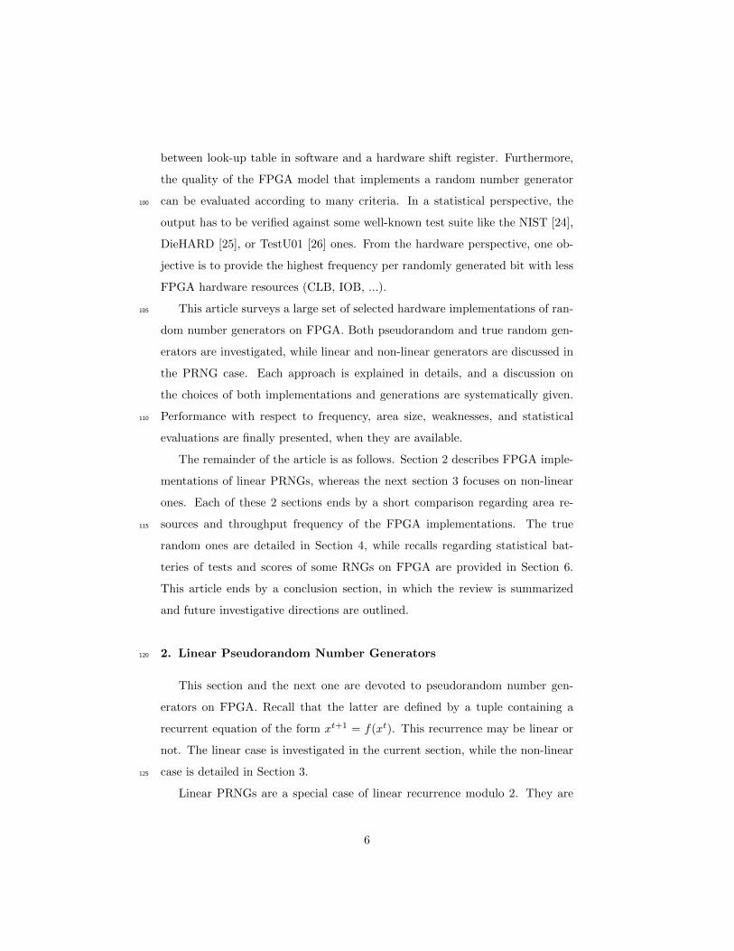
LFSR based Accumulator Generator proposed in [43] is a PRNG based on
Digital Sigma-Delta Modulator [44] made from accumulator circuits. This lat-
ter is used to divide the frequency in a Fractional-n Frequency Synthesizer [45].
Authors of [43] propose a pipeline of N = 9 serial digital accumulators of w = 8
bits based FPGA as described in Figure 4. Each accumulator, which can pro-
duce M = 2w possible values, is a self-recursive structure based on quantization
error mapping function formalized in Eq. (8), where the accumulator’s feedback
coefficients are time-varying, using another linear feedback shift register. The
accumulator, which is presented in Equation (7), is parameterized by the input
seed x0, the accumulator sum p, the carry output accu, the quantization error e,
and the feedback coefficients c = 2−w of the accumulators as outputs. The in-
put of each n = 0, . . . , (N −1) stage during the processing uses the quantization
error et−1 of the previous stage. Therefore, the PRNG gives a better uniform
outputs by propagating the latter (e) at all stages following the Equation (7).
The accumulator feedback coefficient c is implemented with another accumu-
lator. The latter are multiplied by a binary variable dw ∈ {0, 1} of the LFSR
to control the feedback depending on the period of LFSR. The final output
11
source [43]
Figure 4: Block-level model of a w-bit digital accumulator PRNG comprising n stages
yt = eout is the last generated etN−1 evaluated in Equation (8).
pt+1n =
x0 + et0 + accut1d
t0, n = 0
et+1n−1 + etn + accutn+1d
t+1w−1, 0 < n < N − 1
et+1n−1 + etn, n = N − 1
(7)
et+1n = pt+1
n mod 2w and accutn =
1 ptn ≥M
0 ptn < M(8)
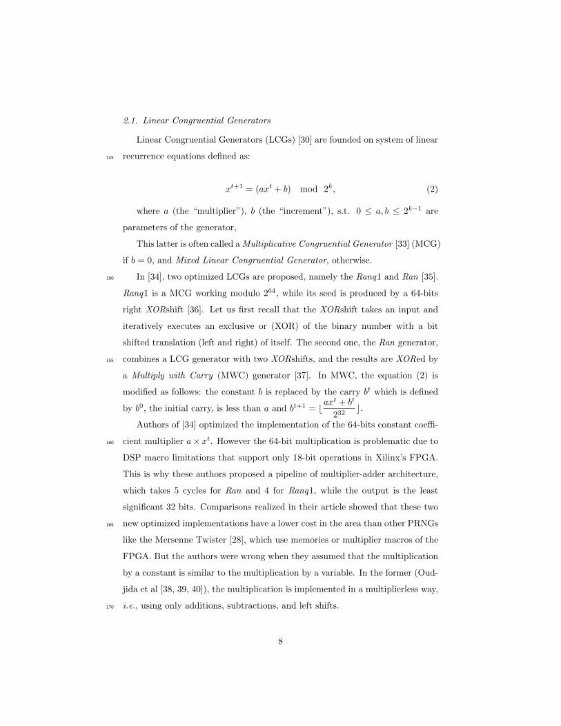
2.3. Look-up Table Optimized Generators
Look-up Table (LUT [23]) optimized generators use logic block as a digital
component defined in a CLB provided by the FPGA vendors. It is used for205
implementing many function and operation generators for a hardware optimiza-
tion purpose. A LUT consists of a block of RAM (Random Access Memory)
implemented as a truth table that is indexed by the LUT inputs.
In [46, 47, 48], the authors present a series of LUT PRNGs based on F2
linear matrix recursive algorithms (see Figure 5). The main idea is to produce210
a maximum efficiency at area level. The authors associate either Flip-Flops
(FF), Shift Registers (SR), or block of RAMs (RAM) with LUT to perform
shift/multiplication operations in FPGA. However, creating long period se-
12
quences T = 2w with this method is a difficult task. To solve this problem,
large optimized LUT based {FF, SR, RAM} pairs are investigated.215
The first proposed PRNG is called LUT-OPT (LUT optimized, (a) in Fig-
ure 5). It maps each row of the recurrence matrix A as a XOR gate using just
LUT and FF. To generate w bits per cycle requires w LUT-FFs in a single
LUT of k-bits during a period of T = 2w where w = k (see Figure 5). Their
estimations of the FPGA resources conclude that even if an application requires220
64 bits for each cycle, their implementations necessarily use 512 LUT-FFs to
produce a period of 2512 − 1. The second one, the LUT-FIFO (b), is used to
increase the period up to T = 2(w+k∗L) without using the pair LUT-FF, which
uses RAM block memory (dual-port RAM) of FPGA as L × k FIFO to store
the recursive sequences. In this case, each new output bit is depending on one225
bit from the last iteration. They next propose a FIFO based shift-register SR
(c) with a fixed length L of 1-bit, to load the w-bit state in parallel instead of
using dual-port RAM. They also propose a LUT-SR PRNG (d) that turns the
use of LUT as a k-bit Shift-Register using “Xilinx SRL32”, with the length of
each “SR” varying as follows: 1 < Li < L. The “Xilinx SRL32”, allows the230
cascading of any number up to 32-bit shift registers to create a shift register
with any size needed.
2.4. Twisted Generalized Feedback Shift Register PRNG
Twisted Generalized Feedback Shift Register (TGFSR) proposed in [32] is
an extension of Generalized Feedback Shift Register “GFSR” [31], which uses235
an array of shift registers to generate more than one bit for each state change.
Therefore, a TGFSR is based on recurrence of N sequences of words, x0, . . . ,
xN−1, each containing k-bits and two parameters, namely a bitmask size c, such
that c 6 k − 1 and a initial median position m with 1 ≤ m ≤ N .
TGFSR computes the t+N -th word (t = 0, 1, . . . ) by operating with three240
words: the first two words xt and xt+1 with the median word xt+m. More
precisely (see Figure 6):
1. It computes the c least significant bits (LSB) of xt+1 and the k − c most
13
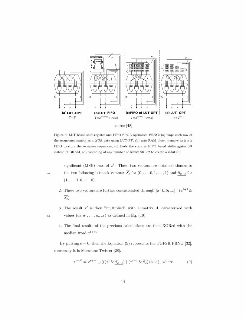
source [48]
Figure 5: LUT based shift-register and FIFO FPGA optimized PRNG: (a) maps each row of
the recurrence matrix as a XOR gate using LUT-FF, (b) uses RAM block memory as k × k
FIFO to store the recursive sequences, (c) loads the state in FIFO based shift-register SR
instead of BRAM, (d) cascading of any number of Xilinx SRL32 to create a k-bit SR
significant (MSB) ones of xt. These two vectors are obtained thanks to
the two following bitmask vectors: Sc for (0, . . . , 0, 1, . . . , 1) and Sk−c for245
(1, . . . , 1, 0, . . . , 0).
2. These two vectors are further concatenated through (xt &Sk−c) | (xt+1 &
Sc).
3. The result x′ is then ”multiplied” with a matrix A, caracterized with
values (a0, a1, . . . , aw−1) as defined in Eq. (10).250
4. The final results of the previous calculations are then XORed with the
median word xt+m.
By putting c = 0, then the Equation (9) represents the TGFSR PRNG [32],
conversely it is Mersenne Twister [28].
xt+N = xt+m ⊕ (((xt & Sk−c) | (xt+1 & Sc))×A), where (9)
14
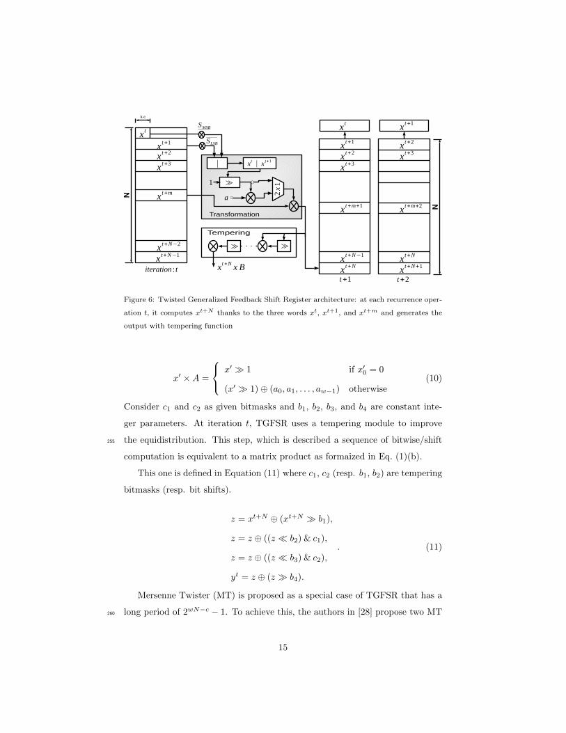
Figure 6: Twisted Generalized Feedback Shift Register architecture: at each recurrence oper-
ation t, it computes xt+N thanks to the three words xt, xt+1, and xt+m and generates the
output with tempering function
x′ ×A =
x′ � 1 if x′0 = 0
(x′ � 1)⊕ (a0, a1, . . . , aw−1) otherwise(10)
Consider c1 and c2 as given bitmasks and b1, b2, b3, and b4 are constant inte-
ger parameters. At iteration t, TGFSR uses a tempering module to improve
the equidistribution. This step, which is described a sequence of bitwise/shift255
computation is equivalent to a matrix product as formaized in Eq. (1)(b).
This one is defined in Equation (11) where c1, c2 (resp. b1, b2) are tempering
bitmasks (resp. bit shifts).
z = xt+N ⊕ (xt+N � b1),
z = z ⊕ ((z � b2) & c1),
z = z ⊕ ((z � b3) & c2),
yt = z ⊕ (z � b4).
. (11)
Mersenne Twister (MT) is proposed as a special case of TGFSR that has a
long period of 2wN−c − 1. To achieve this, the authors in [28] propose two MT260
15
configurations:
• “MT11213” with a period of 211213 − 1 that has w = 32, N = 351, m =
175, c = 19, and a = 0xE4BD75F5 as recurrence parameters, and c1 =
0x655E5280, c2 = 0xFFD58000, b1 = 11, b2 = 7, b3 = 15, and b4 = 17
for tempering ones265
• “MT19937”, which has a period of 219937 − 1, has w = 32, N = 624,
m = 397, c = 31, and a = 0x9908B0DF as recurrence parameters, and
c1 = 0x9D2C5680, c2 = 0xEFC60000, b1 = 11, b2 = 7, b3 = 15, and
b4 = 18] for Tempering ones.
Two FPGA implementations of Mersenne Twisters MT19937 and MT11213270
are proposed in [34] for Monte Carlo applications in finance. The authors imple-
ment many Block RAM memory or namely “BRAM” for matrix multiplications:
a single dual-port BRAM for MT11213 and two dual-port BRAM for MT19937.
The RAM memory, configured in the read-before-write mode, operates like a
feedback shift register. In this mode, the new inputs are stored in memory at275
appropriate write address, while the previous data are transferred to the out-
put ports. This latter coming from BRAM are then processed following the
Equation (6). The same approach has been proposed in [49] for MT19937 using
2 BRAM. Authors of [50], for their part, have implemented the MT11213 in
three platforms for the sake of comparison, namely: FPGA, CPU, and GPU.280
Remark that, for testing the FPGA performances, initial and Tempering matrix
parameters have been extracted from a PC software, due to the hardware cost
consuming by the initialization stage of MT. However, both transformation and
Tempering modules are executed in FPGA. In this case, two dual-port BRAMs
are necessary for the other stages. This structure reduces the area compared285
to other MT implementations in FPGA, and the speed up is about ≈ 9× and
≈ 25× compared to GPU and CPU respectively.
In [51], the authors have proposed two parallel PRNG implementations with
many levels of three different Mersenne Twisters: the MT19937-32bits, the
MT19937-64bits, and the SIMD-oriented Fast Mersenne Twister SFMT19937 [52].290
16

The first one is the Interleaved Parallelization (IP), that generates w-bits for
each P memory block separately.
In the IP configuration, the N = 624-words state vector is located across
multiple memory banks of the same size. Each P memory bank has d in-
put/output ports I/O of w-bits, while each I/O port generates v-bits per clock295
cycle every q read operation. Therefore, the number of clock cycle τ required to
generate a random number is equal to τ = (w ∗ (q+ 1))/v ∗d. The second one is
the Chunked Parallelization (CP), that uses the output bits of each RAM bank
as the far recurrence input for the next RAM bank. Therefore, the N -words
state vector is sequentially split into chunks across a number of banks of differ-300
ent size. Even though the IP version has a better throughput than the CP one,
the latter uses lesser RAM blocks compared to the IP version (3 levels of CP
use 2 BRAMs while IP uses 3).
Authors of [53] give more hardware details for the deployment of RAM mem-
ories. Their MT19937 implementation consists of a transform unit, a Temper305
Unit, a control unit “Crossbar” implemented using 7 multiplexers, a 3R/1W
RAM, and an address unit for RAM access (3 read addresses and 1 address
for writing). The main key of the latter is the implementation of 624 states of
32-bits register using BRAM memory of the FPGA (see Figure 7). Therefore,
instead of fetching the 3 state vectors using 3 BRAM as in [51], two dual-port310
BRAMs of 312×32-bits can perform in each cycle 3 read operations and 1 write
one. The R/W for the first BRAM operates with an even address, while the
second R/W is in the odd address.
In [54], various degrees of parallelization of the MT19937 architecture (of
degrees 2, 3, 4, and 6) implemented in [53] and used for Monte-Carlo based315
simulations are proposed. In this case, the configuration of BRAM is the key of
the parallelism, where each degree corresponds to the number of BRAM that are
used (4 degrees = 4 implemented RAMs). The authors use one 206×32-bit, two
207 × 32-bit dual-port BRAM, and four registers to provide state consistency
for the given parallelized states for 3 degrees as an example. Here, all I/O ports320
of three BRAM are in read mode during initialization, while in the runtime just
17

source [53]
Figure 7: Mersenne Twister MT19937 architecture using 3R/1W BRAM: at each cycle, R/W
address is even address for BRAM0 and odd for BRAM1
one is in read mode (the others being in write mode).
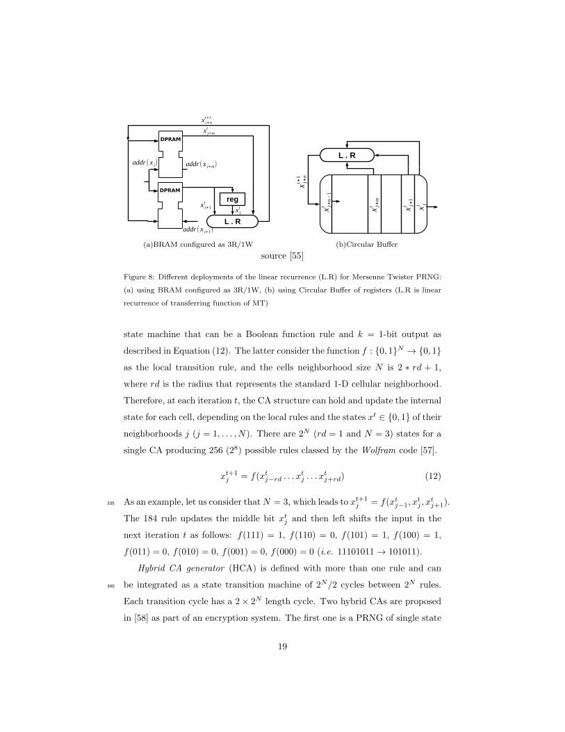
Finally, a recent FPGA implementation of Mersenne Twisters is presented
in [55]. The authors propose an alternative solution of the use of RAMs, which
is named Circular Buffer (CB). It is implemented for MT19937 (see Figure 8).325
The solution is based on the fixed relationship between word indices. Words xtj ,
xtj+1, and xtj+m written in the buffer are passed to the transform unit. At each
iteration, the first word xtj is clocked out of the buffer while new data xt+1j is
written to the free location. By this way, the linear recurrence and the buffer of
registers can be considered as a circular buffer. The linear recurrence is carried330
out by some combinational logic between the input and the output of the buffer.
Therefore, the architecture is simplified since no logic operation for the table
indices is needed.
2.5. Cellular Automata based PRNGs
Cellular Automata (CA) is a discrete model, proposed by John von Neumann
and Stan Ulam [56] as formal models of self-reproducing robots. The basic
representation of one dimensional CA PRNG includes N cells with an internal
18
(a)BRAM configured as 3R/1W (b)Circular Buffer
source [55]
Figure 8: Different deployments of the linear recurrence (L.R) for Mersenne Twister PRNG:
(a) using BRAM configured as 3R/1W, (b) using Circular Buffer of registers (L.R is linear
recurrence of transferring function of MT)
state machine that can be a Boolean function rule and k = 1-bit output as
described in Equation (12). The latter consider the function f : {0, 1}N → {0, 1}
as the local transition rule, and the cells neighborhood size N is 2 ∗ rd + 1,
where rd is the radius that represents the standard 1-D cellular neighborhood.
Therefore, at each iteration t, the CA structure can hold and update the internal
state for each cell, depending on the local rules and the states xt ∈ {0, 1} of their
neighborhoods j (j = 1, . . . , N). There are 2N (rd = 1 and N = 3) states for a
single CA producing 256 (28) possible rules classed by the Wolfram code [57].
xt+1j = f(xtj−rd . . . x
tj . . . x
tj+rd) (12)
As an example, let us consider thatN = 3, which leads to xt+1j = f(xtj−1, x
tj , x
tj+1).335
The 184 rule updates the middle bit xtj and then left shifts the input in the
next iteration t as follows: f(111) = 1, f(110) = 0, f(101) = 1, f(100) = 1,
f(011) = 0, f(010) = 0, f(001) = 0, f(000) = 0 (i.e. 11101011→ 101011).
Hybrid CA generator (HCA) is defined with more than one rule and can
be integrated as a state transition machine of 2N/2 cycles between 2N rules.340
Each transition cycle has a 2× 2N length cycle. Two hybrid CAs are proposed
in [58] as part of an encryption system. The first one is a PRNG of single state
19
transition using rules 90, defined by f(xt1, xt2, x
t3) = xt1 ⊕ xt3, and 150, defined
by f(xt1, xt2, x
t3) = xt1 ⊕ xt2 ⊕ xt3 to generate an encrypting real-time key stream.
The second one is a block cipher of two state transitions, each having 8 cycles345
length with 51/153/195 rules. The aim of this application is to use the first
HCA to select the transition sequences between rules used by each cell of the
second HCA in the block cipher. The FPGA implementation of each CA is done
with a logic combinational circuit (LCC) to define the rules. Then it uses LCG
to control the loading operation of the CA and stores the data into a D flip-flop.350
Authors of [59], for their part, create an automatic software tool to generate
the RTL code of any HCA configuration. Finally, in [60], authors increase the
ratio of frequency/area and the security of their previous PRNG [59] by using
a chain of HCAs instead of a single one.
Mixed CA generator is proposed in [61], where the author mixes the outputs355
of a 37-bits hybrid CA (rules 90 and 150) with a 43-bits LFSR to obtain a large
period. However, some drawbacks of this implementation are revealed during
statistical evaluation, which can be surpassed only if the two PRNGs are clocked
at different clock frequencies. This is why a new solution is presented in [62].
In this article, authors propose to XOR the last bit of HCA with the last bit360
of LFSR to generate 1-bit per clock cycle. As a repercussion, they found that
the optimal combination for a PRNG of high quality is 16-bits for CA with a
37-bits LFSR.
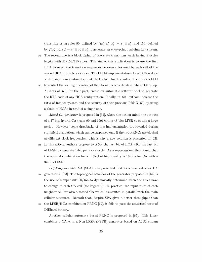
Self-Programmable CA (SPA) was presented first as a new rules for CA
generator in [63]. The topological behavior of the generator proposed in [64] is365
the use of a super-rule 90/156 to dynamically determine when the rules have
to change in each CA cell (see Figure 9). In practice, the input rules of each
neighbor cell are also a second CA which is executed in parallel with the main
cellular automata. Remark that, despite SPA gives a better throughput than
the LFSR/HCA combination PRNG [62], it fails to pass the statistical tests of370
DIEhard battery.
Another cellular automata based PRNG is proposed in [65]. This latter
combines a CA with a Non-LFSR (NSFR) generator based on A2U2 stream
20

source [63]
Figure 9: Self-Programmable cellular automata generator: uses a super-rule 90/156 to dy-
namically determines when the rules have to change in each CA cell
cipher design. Recall that the stream cipher A2U2 [66] was presented as a
new key cryptographic generator of 56-bits for RFID tags application. It has a375
LFSR counter of 7-bits and two non-linear feedback shift registers (NFSRs, 17
and 9-bits). However, NFSR is known for its short period length. Hence, their
main contribution is to associate a CA PRNG of 9-bits to increase the period
of NFSR, both having feedback between them (which means that the seed of
NFSR is provided by CA and vise versa). This approach improves resistance380
to various forms of cryptanalysis like correlation attacks and algebraic ones.
For the sake of completeness, notice that the authors of [67] have proposed a
different implementation concept of the usual rules in CA. In their proposal, the
initial state configuration of CA and its length depend on the current date.
3. Non-Linear Pseudorandom Number Generators385
3.1. Blum Blum Shub based PRNGs on FPGA
Blum Blum Shub generator (BBS) proposed in [68] is a non-linear and cryp-
tographically secure PRNG based on the quadratic residue problem x2 = q
21
mod w, where q is the “quadratic residue”. It works as follows: consider
n = p × q, where p and q are prime numbers that are congruent to 3 mod 4.390
Let x0 be an integer lower than w, which operates as a seed of the BBS
generators. Consider now the recurrent sequence xt+1 = (xt)2 mod w, and
j = blog2(log2(w))c, where bxc is the integral part of x. Then, at iteration t,
the BBS generator outputs the j least significant bits of xt.
Despite its cryptographic security, only a few FPGA implementations of395
BBS can be found in the literature. They are listed hereafter. In [69], the
authors present an area comparison without any optimization between a 4-bits
LFSR and a 16-bits BBS PRNG. Another proposal is provided in [70] for RFID
tag applications. In this article, the authors present a FPGA implementation of
BBS with n ranging from 160 to 512-bits. They consider various modular multi-400
plication algorithms to optimize the main BBS equation. The Montgomery [71]
iterative approach exhibits the lowest cost area. In [72], the authors propose a
hybrid RNG of an off-chip TRNG based on Ring Oscillator 4 and a BBS PRNG
generator implemented in FPGA. The TRNG generates the first random clocked
by a RC circuit used as a seed for BBS. Then, the BBS uses an ALU structure405
to implement the squaring and modulo operations.
3.2. Chaotic PRNG
Chaotic generators (CPRNGs) are non-linear generators of the form x0 ∈ R:
xt+1 = f(xt), where f is a chaotic map. They are attractive applications of the
mathematical theory of chaos. Reasons explaining such an interest encompass410
their sensitivity to initial conditions, their unpredictability, and their ability
of reciprocal synchronization [73]. From a cryptographer point of view, these
chaotic PRNGs have major drawbacks often reported [74].
Chaotic Mapping PRNG are based on a polynomial mapping that uses a non-
linear dynamic transformation, which is a quadratic mapping. Most of these415
generators are based on the Logistic Chaotic Map called also “LCG” map [75],
defined as follows: xt+1 = α × xt(1 − xt), where 0 < xt+1 < 1 and α is the
biotic potential (3.57 < α < 4.0). The logistic map is mainly depending on the
22
parameter α: its chaotic behavior is lost when α is out of the range provided
above. Moreover, if α > 4 and for almost all initial values, the outputs diverge420
and leave the interval [0, 1]. The second most frequently used function is the
Henon chaotic map [76], which takes a point (xt,yt) within the plan square
unit and maps it into a new point (xt+1, yt+1). This map is defined by these
equations: xt+1 = 1 + yt − a(xt)2 and yt+1 = bxt, where a and b are called
canonical parameters.425
In [77], the authors have used fixed point representation [78] to implement
the logistic map using Matlab DSP System Toolbox software. Fixed-point for-
mat is an approximation of real numbers, with much less precision and dy-
namique range than the floating-point format. Nevertheless, it has the merit of
being very efficient in high-speed and low-power applications. This unit requires430
less power and cost to manipulate such kind of numbers than usual floating-point
circuitry. They generate many designs with different lengths from 16 to 64 bits,
where the resources are depending on the precision (24 to 53 bits). The mul-
tiplication is implemented with DSP blocks of FPGA that perform 18x25 bits
multiplications, while the multiplication by a constant α is a simple series of435
add and left-shift operations.
Authors of [79] compare the implementation of logistic map with the Henon
one. Unlike the logistic map, the 64 bits multiplication in Henon [76] map cannot
be implemented with a left shift operation, which leads to the use of DSPs blocks
of the FPGA for all multiplications needed to implement ax2. Two optimized440
versions of PRNGs based on chaotic logistic map are proposed in [80], which
aim to reduce resources and increase frequency, unlike in [77, 79]. The first one
is based on LUT and DSP blocks of the FPGA. The second one rewrites the
logistic map equation as follows: xt+1 = αxt − α(xt)2. The objective of these
two PRNGs is to pipeline the multiplication operations and synchronize them445
while adding some delays into each stage, in order to ensure a parallel execution
of sequences. The outputs are generated for each 8-16 clock cycles and in each
cycle a new seed is inserted.
In [81], the authors vary the biotic potential α and observe the divergence
23

of random for almost all initial values. Accordingly, they propose a range of450
the form [α, 1−α], where the biotic potential is α < 0.5. Another way to select
the parameter α is presented in [82]. They propose a couple of two logistic
map PRNGs, each having different seed and parameter (x0, α1 and y0, α2
respectively), where both generates pseudorandom numbers synchronously. The
main idea is to recycle the pseudorandom number generated by the first chaotic455
map, namely xt+1, as the biotic potential α2 for the second one (yt+1) when
either 3.57 < xt+1 < 4 is satisfied or the sequence output is divergent. Another
coupling chaotic map is presented in [83]. In this work, the former is based
on the Henon map and the latter is an 1-dimension logistic map. The former
is used to generate a random sequence, and the latter controls a multiplexer460
to choose the output of the first one according to the value generated by the
logistic map. The output of the logistic map generator is then decomposed in
32 bits; the first most significant bit is XORed with its neighbor bit. The result
is then XORed again with the next bit until reaching the least significant one.
Finally, in [84] four different chaotic maps are implemented in FPGA, namely,465
the so-called Bernoulli, Chebychev [85], Tent, and Cubic chaotic maps. The
implementation is done with and without FPGA’s DSP blocks for the multi-
plication operations. The results show that the Bernoulli chaotic map gives a
higher ratio of area/power compared to the other chaotic generators.
Spatiotemporal Chaotic PRNG is a temporally chaotic system which is an470
extension of chaotic maps. It is also spatially chaotic (many mathematical
models can be used to represent this type of generator). For instance, in [86] the
authors present a spatiotemporal chaotic PRNG , which is based on a coupled
chaotic map lattices defined as
xt+1i = (1− ε)f(xti) +
ε
2(f(xti−1) + f(xti+1)). (13)
In this equation, t (resp. i = 1, . . . , k ) is a temporal (resp. a spatial) index475
of discrete lattice, ε is the couple parameter, and f is a logistic map. They
first deal with continuous domain digitizing of all operands to be suited for
24

hardware implementation. To achieve this, they consider a particular version of
Equation (13) where x ranges over {0, 1, . . . , 2k− 1} and f is a modified logistic
map, f(x) = b4x(2k − x)
2kc for a k-bits precision. Secondly, to avoid the finite480
precision chaotic map problem, they compute only the insignificant bit which is
subject to be an output. Indeed, for each 25 clock cycles, only the w = 16 most
insignificant bits of the random numbers would be used from each lattice and
the computational precision k = 32.
Chaotic based Timing Reseeding (CTR) proposed first in [87] aim at remov-485
ing the short period problem due to the quantization error from a nonlinear
chaotic map PRNG. Instead of initializing the chaotic PRNG with a new seed,
the seed can be selected by masking the current state xt+1 at a specific time
(see Figure 10). More precisely, the reseeding unit compares the two register
states to check whether a fixed point has been reached. In this case xt+1 is not490
streamed out. It is masked with a constant and the result is stored in the initial
register state. Additionally, it increases the period each time the condition is
true or the reseed period is reached (counter). This main concept of CTR was
first implemented in FPGA [88], in which the Carry Lookahead Adder [89] has
been used to optimise the critical path of the partial products of the multi-495
plication operation. Unlike [88], authors of [90] present more hardware details
for reducing multiplication operation resources. They also mix the output xt+1
with an auxiliary generator zt+1 to improve statistical tests. The mixer module
is a DX generator [91], whose output is as follows: zt+1 = (zt + (228 + 28)zt−7)
mod (231 − 1). Then, the authors add the MSB-bit of xt+1 (32th bit) to the500
31 LSB-bits of the final output yt+1[30 : 0] = xt+1[30 : 0] ⊕ zt+1[30 : 0], which
generates a full 32-bits output state and has a full period. Both uses Circular
Left Shift [92] (CLS) and End-Around Carry Adder [93] (ECA) to optimize the
multiplication operations. They finally suggest to choose a reseeding period
that must be not only prime, but also not a multiple of the nonlinear chaotic505
map PRNG. The same approach has been used in [94] for plaintext encrypt-
ing/decrypting application system.
Differential Chaotic PRNG is a digitized implementation of a nonlinear
25

source [88]
Figure 10: Chaotic based Timing Reseeding PRNG: masking the current state xt+1 at a
specific time (fixed point between the two register states is reached)
chaotic oscillator system in Rossler format [95]. It uses an approximated nu-
merical solution to solve the dynamic system generalization of the Lorenz hy-510
perchaos. A basic representation of the dynamical system is proposed in [96, 97]
Equation (Eq. (14)).
−...X = X +B(X) +X
B(X) =
α1, if X > 1
α2, otherwise,
(14)
where, α1, α2 are integer values in the switch condition. The idea is to
create a chaotic system with a unique equilibrium point at the origin. Indeed,
to guaranties a chaotic generation, B value must switch between α1 >1 and515
α2 < 1.
This latter can expand in more than one direction (i.e., Euler approximation
where Y = X and Z = X) and generates a much more complex attractor
compared to other chaotic systems.
26

The resolution of Equation (14) was the main study done in [98] (with other520
differential systems as the Chen [99] and Elwakil [96] ones). The authors deploy
three different numerical methods for each system: 4th order Runge-Kutta [100],
mid-point [101], and Euler techniques [102]. Unlike the Euler techniques that
only require one calculus per iteration, the mid-point provides more precise
results but longer calculation paths. Additionally, the Runge-Kutta 4th-order525
have the longest calculation path but it has the most accurate numerical approx-
imation. Obviously, Euler techniques show better results for implementation of
differential chaotic methods in FPGA, with respects area and throughput per-
spectives.
More details regarding implementation and optimization of the multiplica-530
tion by a constant in Equation (14) are provided in [103]. In this article, authors
proposed to use the Euler approximation, as illustrated in Equations (15), where
the oscillation margins are within a time interval [h, α1] (h is the Euler step).
Xt+h = Xt + hY t, where Y = X
Y t+h = Y t + hZt, where Z = X
Zt+h = Zt − h(Zt + Y tB(Y t) +Xt)
(15)
Their optimization is based on transformation of the parameters h = 2−a
and α1 = 2b, α2 = 0 to simplify the multiplication to a simple shift operation (a535
and b are positive parameters). They use a Carry Lookahead Adder (CLA) [89]
and a Carry Save Adder (CSA) [104] for the multiplication in the first two
equations of (15), and a Carry Propagate Adder (CPA) [105] for the last one.
Additionally, a post-processing is integrated for better results in statistical tests,
which specifically discards the most significant bits. Authors of [79], for their540
part, have implemented the so-called Oscillator Frequency Dependent Negative
Resistors (OFDNR) [97], which uses the same Euler approximation illustrated
in Equations (15). However they have not detailed the resources they used for
such multiplication on their FPGA (e.g., DSP, LUT, . . . ).
In [106] is presented a non-autonomous four-dimensional hyperchaotic PRNG545
27
based on Rossler differential equations. In such a chaotic system some undesir-
able behaviors can appear. Thus, an advanced process-control is necessary in
order to delay the occurrence of the hyperchaos. Therefore, the authors used
Euler approximation and a control function of 256 bits Linear Feedback Shift
Register (LFSR), whose outputs are multiplied by the appropriate coefficient550
of the control function. However, a post-processing of 256-bits based Fibonacci
LFSR is used to remove the short-term predictability of hyperchaotic generator
and to successfully undergo the statistical tests of NIST batteries. The post
processing combines two loops of rotation and XOR feedback loops. The first
one uses a fixed 1-bit static rotation to suppress the short-term predictability.555
The second one is based on a variable rotation controlled by a Fibonacci series
of k-bits. The differential sensitivity problem is solved by changing any bit while
the other bits is propagating during n-cycles.
Chaotic Iteration based PRNG (CI) has been proposed in [107, 108] to im-
plement a new post processing with the same chaos theory defined by Devaney560
and Li-Yorke. Chaotic iterations are defined by an initial configuration x0, a
function f , and a sequence S said to be a chaotic strategy. At the t-th iteration,
only the St-th cell is iterated. Among many proposed versions, one of them has
been implemented on FPGA using BBS and XORshift PRNGs as generators.
The internal state x is a vector of 16-bits, whereas two 64-bits XORshift gen-565
erators are provided as entropy sources. The outputs are then spread into four
32-bits integers. Then for each integer, there are 16 (2-bits) components that
can be found and every 12 of these components are used to update the states.
Lastly, the 4 least significant bits (LSBs) of the output BBS generator decide if
the state must be updated or not with the considered 13-bits block [109, 110].570
Two new families have then been proposed, which are based on chaotic
iterations [111] [112] (CIPRNG-XOR) on FPGA/ASIC on the one hand, and
on the deletion of an Hamilton Cycle [113] on the other hand. This latter
has to satisfy some balance properties: the associated Markov chain on the n-
cube must be close enough to the uniform distribution. In these first studies,575
the minimum length of the chain between two uniform outputs is larger than
28
109 in [114], and it is equal to 9 in [115], for a Boolean function of 8 binary
variables. The new version on FPGA proposes only one jump in the n-cube and
a permutation, as sufficient condition to pass all statistical tests in NIST and
TestU01.580
4. True Random Number Generators
We focus now on FPGA implementations of truly random number generators
(TRNGs). FPGA based TRNGs are physical generators that use various hard-
ware components of FPGAs to produce random-like numbers in a faster way
than using software. These TRNGs use, as entropy source, either the electronic585
noise of embedded components or some environmental sensors (temperature,
noise, and so on). FPGAs are thus efficient and inexpensive random number
generators. Various techniques and hardware optimizations have already been
proposed in the literature, while FPGA components have been used in RNG con-
text for optimization, mixing with external components, or as post-processors.590
4.1. Phase-Locked Loop TRNGs
The Phase-Locked Loop (PLL) [21] is a circuit derived from an external
clock generator source like a quartz or a “Resistor Capacitor” circuit, which
can be configured to produce a signal whose phase is associated to the phase of
the input signal (see Figure 11a). This latter depends on the physical environ-595
ment (power, temperature, or any other physical quantity), and it uses a jitter
extraction technique as random stream, which is indeed a short-term variation
of the clock propagation. Analog PLLs use the jitter caused by Voltage Con-
trolled Oscillator (VCO) noise, while digital PLL [116] generators extract their
randomness from synchronous/asynchronous Flip-Flop components. The most600
common jitter measurements used by FPGA vendors are, namely, the period
jitter and the cycle-to-cycle one. The first jitter is defined as the difference
between the n-th clock period and the mean clock period, while cycle-to-cycle
jitter consists of the difference between adjacent clock cycles in the collection of
sampled clock periods.605
29

(a)PLL architecture (b)PLL timing
Figure 11: Phase-Locked Loop TRNG: detecting the jitter by sampling the reference clock
signal TCLK using a correlated signal TCLJ synthesized in the PLL
The authors of [117] have proposed an analysis about extracting random-
ness from the jitter of a PLL implemented on an Altera FPGA. Their study
is based on detecting the jitter by sampling the reference clock signal TCLK
using a correlated signal TCLJ synthesized in the PLL, where TCLJ = TCLK ×
(KM/KD) with KM and KD as PLL multiplier and divider that must be
prime number constants. According to [117], the maximum distance, further
denoted as max(∆Tmin), between the two clocks CLK and CLJ must satisfy
max(∆Tmin) < σjit to be able to extract randomness. Indeed, according to the
authors, in ideal environmental conditions, we have σjit = 0 (we do not have
any jitter). In that situation, the sampled outputs are deterministic and can be
represented by a series of a bitwise addition of KD input. According to these
authors, the period in that situation is equal to TQ = KDTCLK = KMTCLJ .
Contrarily, in real case conditions, σjit is necessarily negative, and so the output
loses its deterministic character and becomes random. Indeed, the maximum
distance max(∆Tmin) between the two clocks is dependent on the jitter dis-
tribution, while the outputs has a direct impact by this latter following the
expression [117]:
xt(nTCLK) = x
(nTCLK)−i∑
j=0
Jτj
, (16)
where τ is the jitter and J is the value of the output influenced by the jitter. The
30
period is changed in max(∆Tmin) = TCLK × GCD(2KM ,KD)/(4KM ), where
KD is odd and max(∆Tmin) is divided by 2.
This research work has been deepened in [118] by combining more than one
PLL either in parallel or in series. By doing so and due to this combination,
the sensitivity S to the jitter effect is significantly increased according to the
formula:
S = TCLK max(∆Tmin). (17)
As expected, the lowest sensitivity is achievable by using only one PLL. In
that case, the number of random samples and their entropy are low, due to a610
low value of S. To solve this problem, the authors add a second PLL, either
in parallel or in a cascaded configuration, the objective being to increase the
entropy without increasing too much the sensitivity.
Authors of [119] have tested the impact of “environmental” PLL conditions
(encompassing its temperature, its bandwidth, etc.) on the statistical quality615
of the produced output. They have deduced that a low bandwidth of PLL
causes a higher number of critical samples, which decreases the output jitter,
and consequently increases the tracking jitter. Finally, authors in [120] propose
two configurations of PLL based TRNGs in embedded systems.
4.2. Ring Oscillator TRNGs620
A Ring Oscillator (RO) is a series of an odd number of NOT gates, whose
outputs states are balanced between two voltage levels, i.e., between bit 0 an
bit 1. The NOT gates, or Inverter Ring Oscillators IROs, are cascaded, while
the output of the last inverter is fed back to the first inverter of that chain (see
Figure 12). In [121, 122], the authors have proposed a TRNG based on two ring625
oscillators. This latter is rated by different clocks generated by an internal PLL
implemented on FPGA. The authors have also extracted the jitter of the 2 ROs
implemented in only one CLB slice.
Similarly, the authors of [123], have proposed an approach that combines
ROs based on inverters with XOR gates. Their approach is close to the LFSR630
one, except that they use inverters, the latter being combined either using the
31
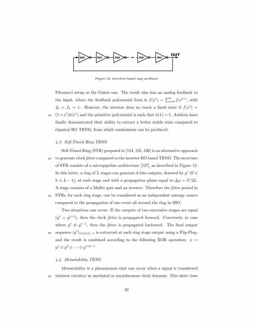
Figure 12: Inverters based ring oscillator
Fibonacci setup or the Galois one. The result also has an analog feedback to
the input, where the feedback polynomial form is f(xt) =∑ki=0 fix
t+i, with
f0 = fk = 1. However, the inverter does no reach a fixed state if f(xt) =
(1 + xt)h(xt) and the primitive polynomial is such that h(1) = 1. Authors have635
finally demonstrated their ability to extract a better stable state compared to
classical RO TRNG, from which randomness can be produced.
4.3. Self-Timed Ring TRNG
Self-Timed Ring (STR) proposed in [124, 125, 126] is an alternative approach
to generate clock jitter compared to the inverter RO based TRNG. The structure640
of STR consists of a micropipeline architecture [127], as described in Figure 13.
In this latter, a ring of L stages can generate k-bits outputs, denoted by yt (0 6
k 6 L − 1), at each stage and with a propagation phase equal to ∆ϕ = T/2L.
A stage consists of a Muller gate and an inverter. Therefore the jitter period in
STRs, for each ring stage, can be considered as an independent entropy source645
compared to the propagation of one event all around the ring in IRO.
Two situations can occur. If the outputs of two successive stages are equal
(yt = yt+1), then the clock jitter is propagated forward. Conversely, in case
where yt 6= yt−1, then the jitter is propagated backward. The final output
sequence (yt)16k6L−1 is extracted at each ring stage output using a Flip-Flop,650
and the result is combined according to the following XOR operation: ψ =
y1 ⊕ y2 ⊕ · · · ⊕ yt+k−1.
4.4. Metastability TRNG
Metastability is a phenomenon that can occur when a signal is transferred
between circuitry in unrelated or asynchronous clock domains. This short time655
32
source [124]
Figure 13: Self-Timed ring architecture: at each ring stage L (Muller gate and an inverter),
the jitter is propagated forward if yt = yt+1 or conversely backward, when the output is the
XOR of each extracted jitter by a Flip-Flop
phenomenon can cause system failures in digital devices.
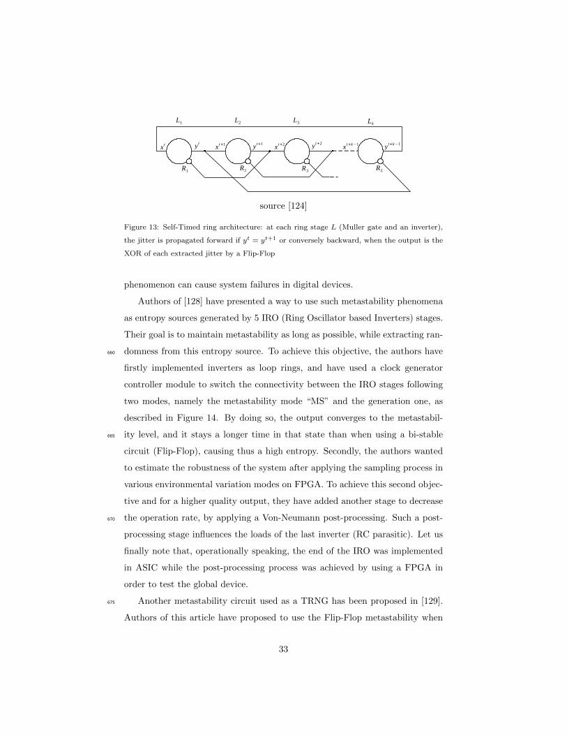
Authors of [128] have presented a way to use such metastability phenomena
as entropy sources generated by 5 IRO (Ring Oscillator based Inverters) stages.
Their goal is to maintain metastability as long as possible, while extracting ran-
domness from this entropy source. To achieve this objective, the authors have660
firstly implemented inverters as loop rings, and have used a clock generator
controller module to switch the connectivity between the IRO stages following
two modes, namely the metastability mode “MS” and the generation one, as
described in Figure 14. By doing so, the output converges to the metastabil-
ity level, and it stays a longer time in that state than when using a bi-stable665
circuit (Flip-Flop), causing thus a high entropy. Secondly, the authors wanted
to estimate the robustness of the system after applying the sampling process in
various environmental variation modes on FPGA. To achieve this second objec-
tive and for a higher quality output, they have added another stage to decrease
the operation rate, by applying a Von-Neumann post-processing. Such a post-670
processing stage influences the loads of the last inverter (RC parasitic). Let us
finally note that, operationally speaking, the end of the IRO was implemented
in ASIC while the post-processing process was achieved by using a FPGA in
order to test the global device.
Another metastability circuit used as a TRNG has been proposed in [129].675
Authors of this article have proposed to use the Flip-Flop metastability when
33
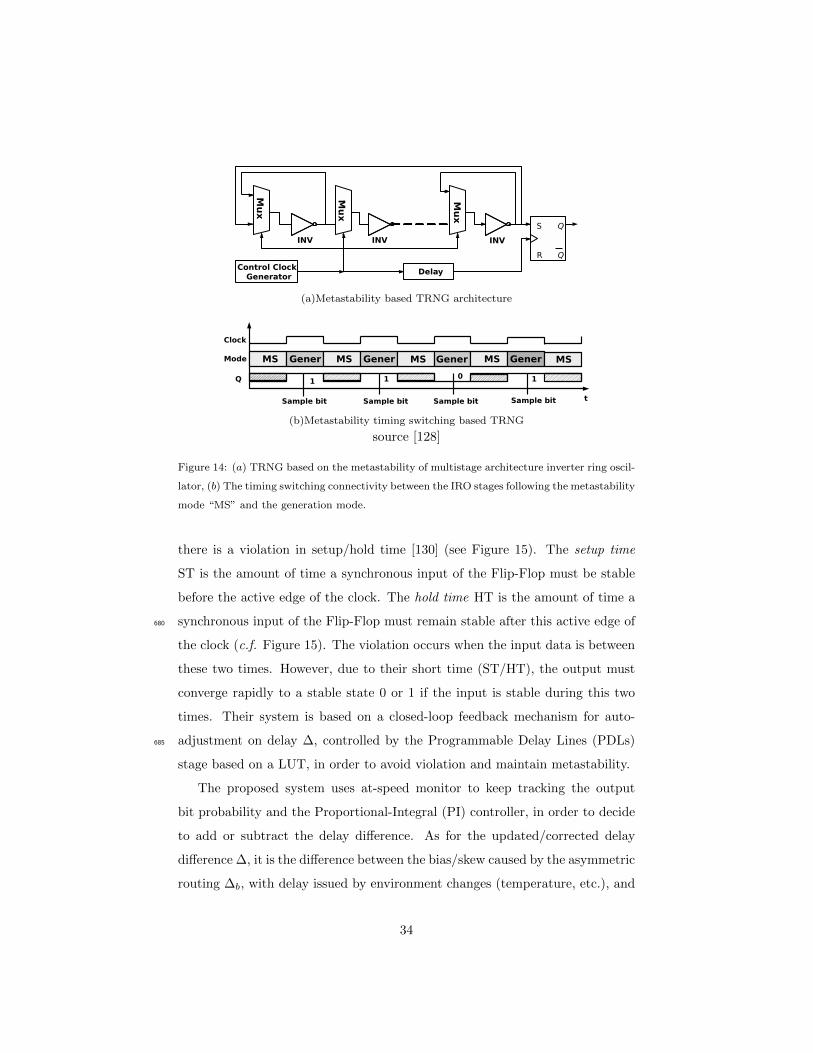
(a)Metastability based TRNG architecture
(b)Metastability timing switching based TRNG
source [128]
Figure 14: (a) TRNG based on the metastability of multistage architecture inverter ring oscil-
lator, (b) The timing switching connectivity between the IRO stages following the metastability
mode “MS” and the generation mode.
there is a violation in setup/hold time [130] (see Figure 15). The setup time
ST is the amount of time a synchronous input of the Flip-Flop must be stable
before the active edge of the clock. The hold time HT is the amount of time a
synchronous input of the Flip-Flop must remain stable after this active edge of680
the clock (c.f. Figure 15). The violation occurs when the input data is between
these two times. However, due to their short time (ST/HT), the output must
converge rapidly to a stable state 0 or 1 if the input is stable during this two
times. Their system is based on a closed-loop feedback mechanism for auto-
adjustment on delay ∆, controlled by the Programmable Delay Lines (PDLs)685
stage based on a LUT, in order to avoid violation and maintain metastability.
The proposed system uses at-speed monitor to keep tracking the output
bit probability and the Proportional-Integral (PI) controller, in order to decide
to add or subtract the delay difference. As for the updated/corrected delay
difference ∆, it is the difference between the bias/skew caused by the asymmetric
routing ∆b, with delay issued by environment changes (temperature, etc.), and
34
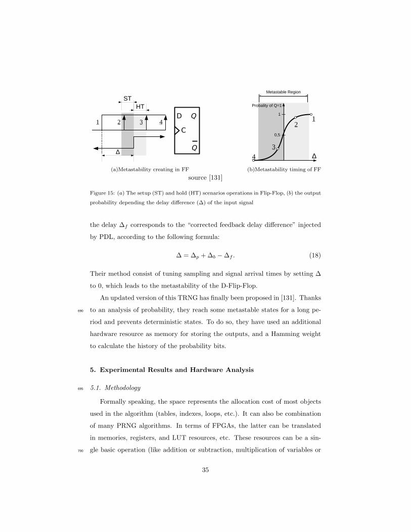
(a)Metastability creating in FF (b)Metastability timing of FF
source [131]
Figure 15: (a) The setup (ST) and hold (HT) scenarios operations in Flip-Flop, (b) the output
probability depending the delay difference (∆) of the input signal
the delay ∆f corresponds to the “corrected feedback delay difference” injected
by PDL, according to the following formula:
∆ = ∆p + ∆b −∆f . (18)
Their method consist of tuning sampling and signal arrival times by setting ∆
to 0, which leads to the metastability of the D-Flip-Flop.
An updated version of this TRNG has finally been proposed in [131]. Thanks
to an analysis of probability, they reach some metastable states for a long pe-690
riod and prevents deterministic states. To do so, they have used an additional
hardware resource as memory for storing the outputs, and a Hamming weight
to calculate the history of the probability bits.
5. Experimental Results and Hardware Analysis
5.1. Methodology695
Formally speaking, the space represents the allocation cost of most objects
used in the algorithm (tables, indexes, loops, etc.). It can also be combination
of many PRNG algorithms. In terms of FPGAs, the latter can be translated
in memories, registers, and LUT resources, etc. These resources can be a sin-
gle basic operation (like addition or subtraction, multiplication of variables or700
35
constants), algebraic functions (division, modulo, etc.), or any other elementary
function. The question raised in this section is thus: how much hardware re-
sources are needed to provide pseudorandom numbers with a good statistical
profile? And which algorithms outperform the other ones in terms of internal
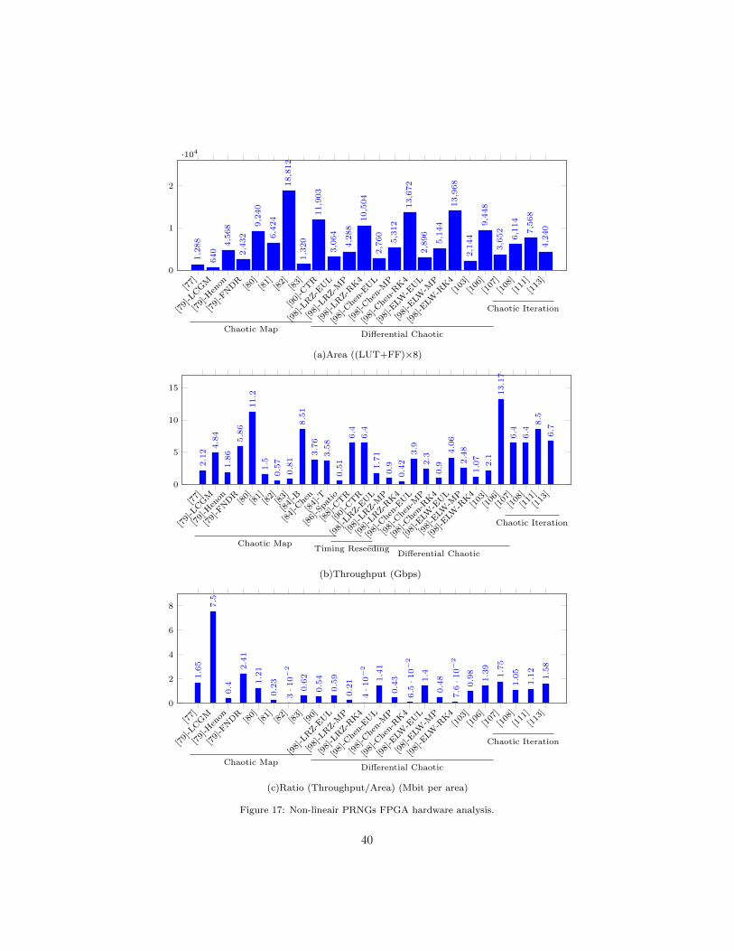
resources, while providing higher throughput?705
Almost aforementioned (P)RNGs have been evaluated regarding their hard-
ware performance according to three parameters: (1) the area, which is the
result of (LUT + FF ) × 8, (2) the throughput being the frequency (clock-to-
setup) multiplied by the RNG output length for one clock cycle, and (3) the
ratio between throughput over area in Mega bits per area unit.710
5.2. Hardware Comparison
Hardware implementation resources required by linear (P)RNGs, their through-
put, and the rate area over throughput are presented in Figure 16, when non-
linear ones are in Figure 17. Finally, the TRNGs are represented in Figure 18.
Let us start start to discuss the results obtained with linear PRNGs, as illus-715
trated in Figure 16. It appears clearly that the cellular automata has the lowest
area, when compared to the other approaches. Such results can be explained
by the need of a low amount of resources to store both the states and the rules
in the cellular automata. Conversely, the TGFSR family deploys BRAM block
memories to read 3 word and write the output in one cycle, whereas LFSR family720
uses more LUTs in order to parallelize the shifting process based on the poly-
nomial equation. Another parameter is the use of black box as DSP and block
memories. The latter optimize the logic operation as multiplication, support
the floating point, store internal process in a multidimensional bloc, and finally
read and write multiple states in parallel from the BRAM. These advantages,725
leading to the difficulty to compare such designs to other ones that do not have
that, lead naturally to further area bloc consumption in the case of an ASIC im-
plementation. As a consequence, we will consider that (P)RNGs without black
boxes are better and more recommended for cryptographic applications.
In terms of area, the PRNGs based on cellular automata [62, 64, 67] have730
36

the lowest resource occupation of FPGA, if we compare them to the other
ones (see Figure 16a). By comparison, the PRNG based on LFSR [41] is 76
times larger. We can also remark that most TGFSR implementations do not
consider the seed process, while its computing increases the area and decreases
the throughput, during the load of 632 words sequentially in the block memories.735
The throughput, for its part, is completely related to both data path and width
(dynamic range) of the design. Additionally, we must take under consideration
the fact that most linear PRNGs are 32 bits ones, while the throughput increases
with generators manipulating more than 64 bits. However, as stated previously,
disabling DSPs and Block memories induces a decrease in the frequency and740
the throughput respectively. Figure 16b illustrates opposed results for the area,
where the LFSR based LUT family has the largest throughput of 343 Gbps,
while it is 5 Gbps for the Mersenne Twister. However, the latter are for 1, 042
bits and 128 bits respectively, when for 32 bits, we have 128 Gbps for the LFSR-
LUT [48].745
Let us focus now on the Throughput/Area ratio (see Figure 16c). Here,
the LUT and shift register based design [48] outperforms all the other linear
PRNGs: the ratio is twice as efficient as the second best one [54], which is the
Mersenne Twister based PRNG with parallel BRAM.
The performance of PRNGs belonging in the chaotic category are illustrated750
in Figure 17. The one that is based on the logistic map has the lowest area oc-
cupation. However, some differential chaotic PRNGs can be presented as good
competitors, namely the chaotic iterations based PRNGs. Results obtained con-
cerning area (Figure 17a) can be explained by the use of a basic operation (the
shift one), and because the bionic coefficient α can be considered as a constant755
when implementing the logistic map. PRNGs based on chaotic iterations, for
their part, need to embed linear PRNGs for their strategies: on the one hand,
CIPRNG-XOR uses 3 PRNGs, while on the other hand ICGPRNG manipulates
only one, but with a permutation function. Figure 17b illustrates the superiority
of chaotic iterations family, in which the differential PRNG based Euler opti-760
mization [103], an optimized logistic map [82], and these PRNG based chaotic
37
iterations [113] have the largest throughput in this category of chaotic genera-
tors. Regarding the Throughput/Area ratio in Figure 17c, the chaotic PRNG
based on LCGM [79] outperforms all the other linear PRNGs: the ratio is 4.1
times more efficient than the second best one [107], which is a chaotic iterations765
generator based on BBS and XORshift.
Finally, considering the TRNG analysis, only a throughput comparison is
provided in Figure 18. Indeed, all the considered authors prefer not to discuss
about area... which is so low when compared with PRNGs. Hence, even with
this main advantage of optimized resources usage, the throughput is too low770
and it ranges from Hz to just a few kHz. Compared to PRNGs, TRNGs are
probably more secure, while PRNGs can be deploied as fast generators.
As a conclusion, linear PRNGs can play an important role for FPGA ap-
plications, due to their rapidity and parallel generation, if we compare them
to other pseudorandom generators. Chaotic PRNGs, for their part, are more775
secure. They are non linear PRNGs and have low hardware resources compared
to the linear ones. Finally, despite the low throughput generated by the TRNG,
they are still consuming only a few logic while generating a real random output.
6. Statistical Test Analysis
Statistical tests are used to evaluate whether the output of a given RNG780
can be separated from a real random sequence obtained, for instance, by rolling
a dice. Such tests are usually grouped in “Batteries”, like the FIPS [132],
DieHARD [25], NIST SP800 − 22 [133], TestU01 [26], or AIS [134] ones. In
what follows, the content of these tests is recalled, for completeness purpose so
as to make our article self-contained.785
The National Institute of Standard and Technologies introduced their first
test battery namely Federal Information Processing Standard (FIPS) 140-1 [132]
in 1994. These quick result tests have been further updated to the FIPS 140-
2 [135] version, which covers more complex test batteries (focused for instance
on security level).790
38

[42]-S
G
[42]-A
SG
[41]-S
G
[41]-P
L
[48]-L
UT
[48]-F
IFO
[48]-S
R[50]
[53]
[54]-2
d
[54]-6
p[62]
[64]
[67]
0
1
2
3
·104
6,3
36 1
2,3
36
7,3
92
10,7
12 16,3
84
25,5
84
19,9
68
3,2
48
2,3
60
2,1
28
5,3
52
472
344
984
LFSR TGFSR CA
(a)Area ((LUT+FF)×8)
[42]-S
G
[42]-A
SG
[34]-R
an
[34]-R
an1
[41]-S
G
[41]-P
L
[48]-L
UT
[48]-F
IFO
[48]-S
R
[34]-M
T19
937
[34]-M
T11
213
[49]
[50]
[51]-M
T-3
2ip
[51]-M
T-3
2cp
[51]-M
T-6
4ip
[51]-M
T-6
4cp
[51]sfmt-12
8cp
[53]
[54]-2
d
[54]-6
p
[55]-cb
[55]-3
p[58]
[60]
[62]
[64]
[67]
0
200
400
3.2
6
6.4
6
10.2
4
12.8
4.7 13.3
128.6
48
343.2
4.9
5.5
0.7
8
8.5 22.3
24 43.9
42.6
107.5
14.4
16.7 44.6
10.8
11
2·1
0−
2
2.4·1
0−
2
2.3
5·1
0−
2
0.2
4LFSR
TGFSR
CA
(b)Throughput (Gbps)
[42]-S
G
[42]-A
SG
[41]-S
G
[41]-P
L
[48]-L
UT
[48]-F
IFO
[48]-S
R[50]
[53]
[54]-M
T-2
d
[54]-M
T-6
p[62]
[64]
[67]
0
5
10
15
20
0.5
1
0.5
2
0.6
4
1.2
4
7.8
5
1.8
8
17.2
2.6
2
6.1
7.8
5
8.3
3
4.8
7
0.1
5
0.2
3
LFSR TGFSR CA
(c)Ratio (Throughput/Area) (Mbit per area)
Figure 16: Linear PRNGs FPGA hardware analysis.
39
[77]
[79]-L
CGM
[79]-H
enon
[79]-F
NDR
[80]
[81]
[82]
[83]
[90]-C
TR
[98]-L
RZ-E
UL
[98]-L
RZ-M
P
[98]-L
RZ-R
K4
[98]-C
hen-
EUL
[98]-C
hen-
MP
[98]-C
hen-
RK4
[98]-E
LW-E
UL
[98]-E
LW-M
P
[98]-E
LW-R
K4
[103
]
[106
]
[107
]
[108
]
[111
]
[113
]0
1
2
·104
1,2
88
640
4,5
68
2,4
32
9,2
40
6,4
24
18,8
12
1,3
20
11,9
03
3,0
64
4,2
88
10,5
04
2,7
60
5,3
12
13,6
72
2,8
96
5,1
44
13,9
68
2,1
44
9,4
48
3,6
52
6,1
14
7,5
68
4,2
40
Chaotic MapDifferential Chaotic
Chaotic Iteration
(a)Area ((LUT+FF)×8)
[77]
[79]-L
CGM
[79]-H
enon
[79]-F
NDR
[80]
[81]
[82]
[83]
[84]-B
[84]-C
hen
[84]-T
[86]-S
patio
[88]-C
TR
[90]-C
TR
[98]-L
RZ-E
UL
[98]-L
RZ-M
P
[98]-L
RZ-R
K4
[98]-C
hen-
EUL
[98]-C
hen-
MP
[98]-C
hen-
RK4
[98]-E
LW-E
UL
[98]-E
LW-M
P
[98]-E
LW-R
K4
[103
]
[106
]
[107
]
[108
]
[111
]
[113
]0
5
10
15
2.1
2
4.8
4
1.8
6
5.8
6
11.2
1.5
0.5
7
0.8
1
8.5
1
3.7
6
3.5
8
0.5
1
6.4
6.4
1.7
1
0.9
0.4
2
3.9
2.3
0.9
4.0
6
2.4
8
1.0
7
2.1
13.1
7
6.4
6.4
8.5
6.7
Chaotic MapTiming Reseeding
Differential Chaotic
Chaotic Iteration
(b)Throughput (Gbps)
[77]
[79]-L
CGM
[79]-H
enon
[79]-F
NDR
[80]
[81]
[82]
[83]
[90]
[98]-L
RZ-E
UL
[98]-L
RZ-M
P
[98]-L
RZ-R
K4
[98]-C
hen-
EUL
[98]-C
hen-
MP
[98]-C
hen-
RK4
[98]-E
LW-E
UL
[98]-E
LW-M
P
[98]-E
LW-R
K4
[103
]
[106
]
[107
]
[108
]
[111
]
[113
]0
2
4
6
8
1.6
5
7.5
0.4
2.4
1
1.2
1
0.2
3
3·1
0−
2
0.6
2
0.5
4
0.5
9
0.2
1
4·1
0−
2
1.4
1
0.4
3
6.5·1
0−
2
1.4
0.4
8
7.6·1
0−
2
0.9
8
1.3
9
1.7
5
1.0
5
1.1
2
1.5
8
Chaotic MapDifferential Chaotic
Chaotic Iteration
(c)Ratio (Throughput/Area) (Mbit per area)
Figure 17: Non-lineair PRNGs FPGA hardware analysis.
40

[117
]-PLL
[118
]-PLL
[120
]-PLL
[121
]-RO
[122
]-RO
[123
]-RO
[124
]-ST
R
[128
]-CI
[129
]-CI
0
20
40
60
80
69
1.9
2 12.8
0.5
9 12.5
13.8
10
50
2
PLL RO Self Timed Ring Metastability
Figure 18: TRNGs FPGA implementation analysis: Throughput (Mbps).
Meanwhile, the DieHARD battery has been proposed by George Marsaglia [25].
It contains 18 tests of randomness. It was designed to provide a better way of
analysis in comparison to the previously released NIST tests. Unlike this latter,
the p-values have now to belong to some fixed chosen interval [α, 1 − α], with
a signification level of α for 5% for instance. An example of these batteries795
are: “Birthday spacings”, “Overlapping permutations”, “Ranks of matrices”,
“Monkey tests”, “Count the 1′s”, “Parking lot”, “Minimum distance”, “Ran-
dom spheres”, “The sqeeze”, “Overlapping sums”, “Runs”, and “The craps”.
The AIS-31 battery [134] is a German standard to test and evaluate the
security properties of truly random number generators. It uses 9 statistical800
tests for the evaluation of a TRNG. AIS can be divided in two categories: the
first one consists of T0-T4, which are the same function of FIPS 140-1 [132].
These later are mostly used to test the outputs of a post-processing. T0 is
the “disjointedness test”, which collects 65536 of 48-bit and verifies that two
adjacent values must not be equal. T1 is the monobit test, T2 is the poker805
test, T3 is the run test, and T4 is the longest run test. As for T5, it is part, is
the auto-correlation test, and T6 is a “uniform distribution test” including of 2
sub-tests. T7 is a “comparative test for multinomial distributions”, and finally
T8 is an entropy test (Coron’s test).
In the other side, National Institute of Standard and Technologies introduces810
41
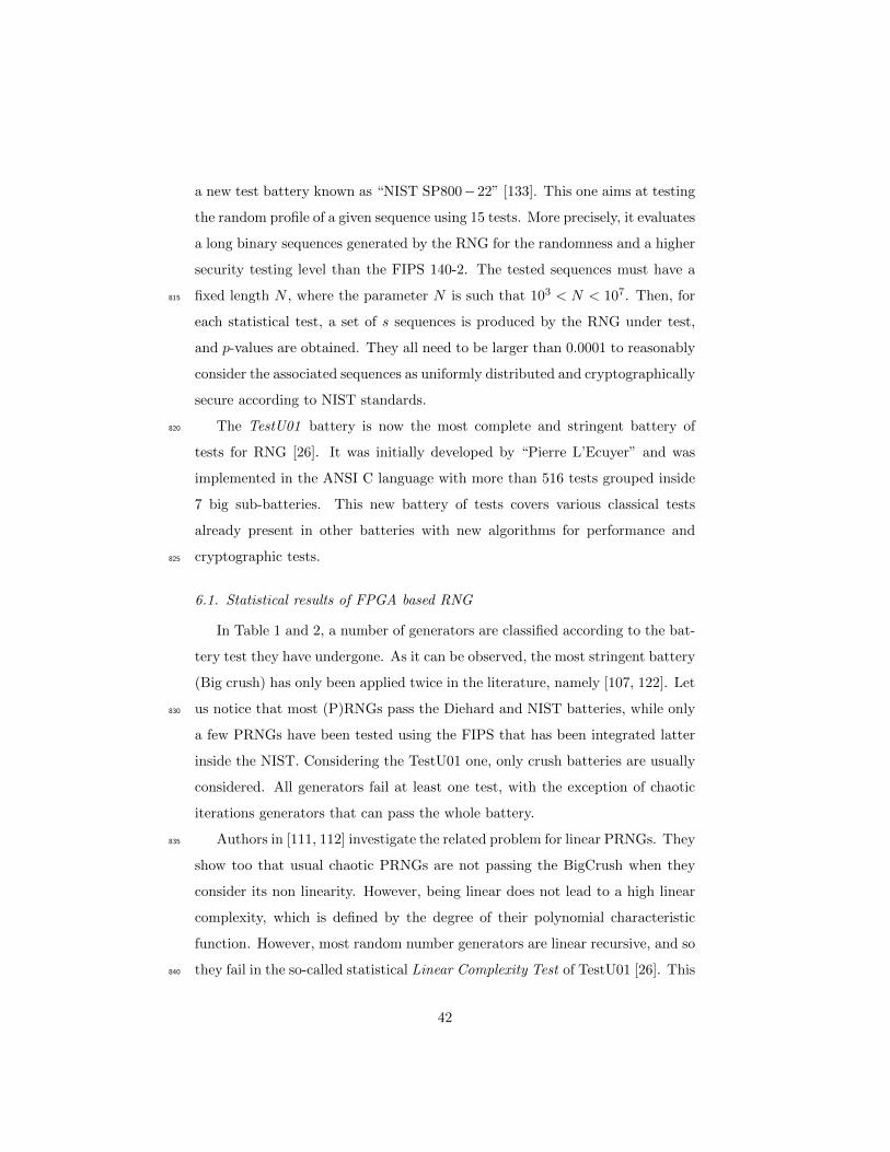
a new test battery known as “NIST SP800−22” [133]. This one aims at testing
the random profile of a given sequence using 15 tests. More precisely, it evaluates
a long binary sequences generated by the RNG for the randomness and a higher
security testing level than the FIPS 140-2. The tested sequences must have a
fixed length N , where the parameter N is such that 103 < N < 107. Then, for815
each statistical test, a set of s sequences is produced by the RNG under test,
and p-values are obtained. They all need to be larger than 0.0001 to reasonably
consider the associated sequences as uniformly distributed and cryptographically
secure according to NIST standards.
The TestU01 battery is now the most complete and stringent battery of820
tests for RNG [26]. It was initially developed by “Pierre L’Ecuyer” and was
implemented in the ANSI C language with more than 516 tests grouped inside
7 big sub-batteries. This new battery of tests covers various classical tests
already present in other batteries with new algorithms for performance and
cryptographic tests.825
6.1. Statistical results of FPGA based RNG
In Table 1 and 2, a number of generators are classified according to the bat-
tery test they have undergone. As it can be observed, the most stringent battery
(Big crush) has only been applied twice in the literature, namely [107, 122]. Let
us notice that most (P)RNGs pass the Diehard and NIST batteries, while only830
a few PRNGs have been tested using the FIPS that has been integrated latter
inside the NIST. Considering the TestU01 one, only crush batteries are usually
considered. All generators fail at least one test, with the exception of chaotic
iterations generators that can pass the whole battery.
Authors in [111, 112] investigate the related problem for linear PRNGs. They835
show too that usual chaotic PRNGs are not passing the BigCrush when they
consider its non linearity. However, being linear does not lead to a high linear
complexity, which is defined by the degree of their polynomial characteristic
function. However, most random number generators are linear recursive, and so
they fail in the so-called statistical Linear Complexity Test of TestU01 [26]. This840
42
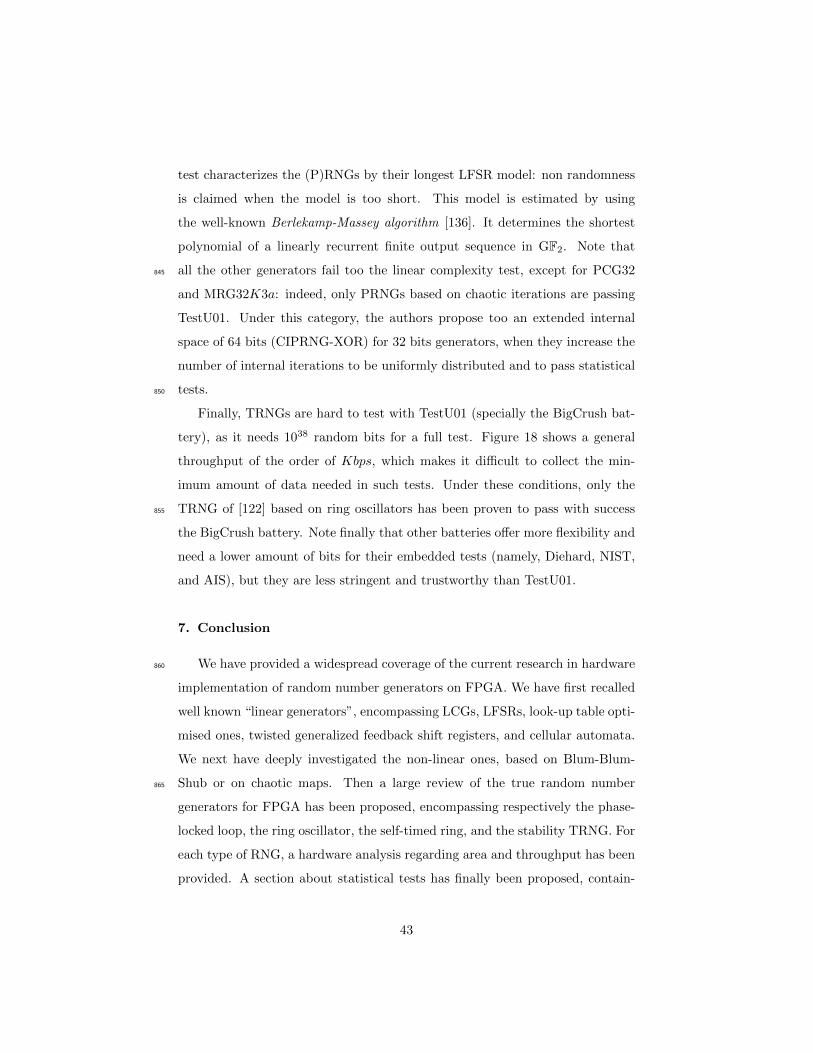
test characterizes the (P)RNGs by their longest LFSR model: non randomness
is claimed when the model is too short. This model is estimated by using
the well-known Berlekamp-Massey algorithm [136]. It determines the shortest
polynomial of a linearly recurrent finite output sequence in GF2. Note that
all the other generators fail too the linear complexity test, except for PCG32845
and MRG32K3a: indeed, only PRNGs based on chaotic iterations are passing
TestU01. Under this category, the authors propose too an extended internal
space of 64 bits (CIPRNG-XOR) for 32 bits generators, when they increase the
number of internal iterations to be uniformly distributed and to pass statistical
tests.850
Finally, TRNGs are hard to test with TestU01 (specially the BigCrush bat-
tery), as it needs 1038 random bits for a full test. Figure 18 shows a general
throughput of the order of Kbps, which makes it difficult to collect the min-
imum amount of data needed in such tests. Under these conditions, only the
TRNG of [122] based on ring oscillators has been proven to pass with success855
the BigCrush battery. Note finally that other batteries offer more flexibility and
need a lower amount of bits for their embedded tests (namely, Diehard, NIST,
and AIS), but they are less stringent and trustworthy than TestU01.
7. Conclusion
We have provided a widespread coverage of the current research in hardware860
implementation of random number generators on FPGA. We have first recalled
well known “linear generators”, encompassing LCGs, LFSRs, look-up table opti-
mised ones, twisted generalized feedback shift registers, and cellular automata.
We next have deeply investigated the non-linear ones, based on Blum-Blum-
Shub or on chaotic maps. Then a large review of the true random number865
generators for FPGA has been proposed, encompassing respectively the phase-
locked loop, the ring oscillator, the self-timed ring, and the stability TRNG. For
each type of RNG, a hardware analysis regarding area and throughput has been
provided. A section about statistical tests has finally been proposed, contain-
43
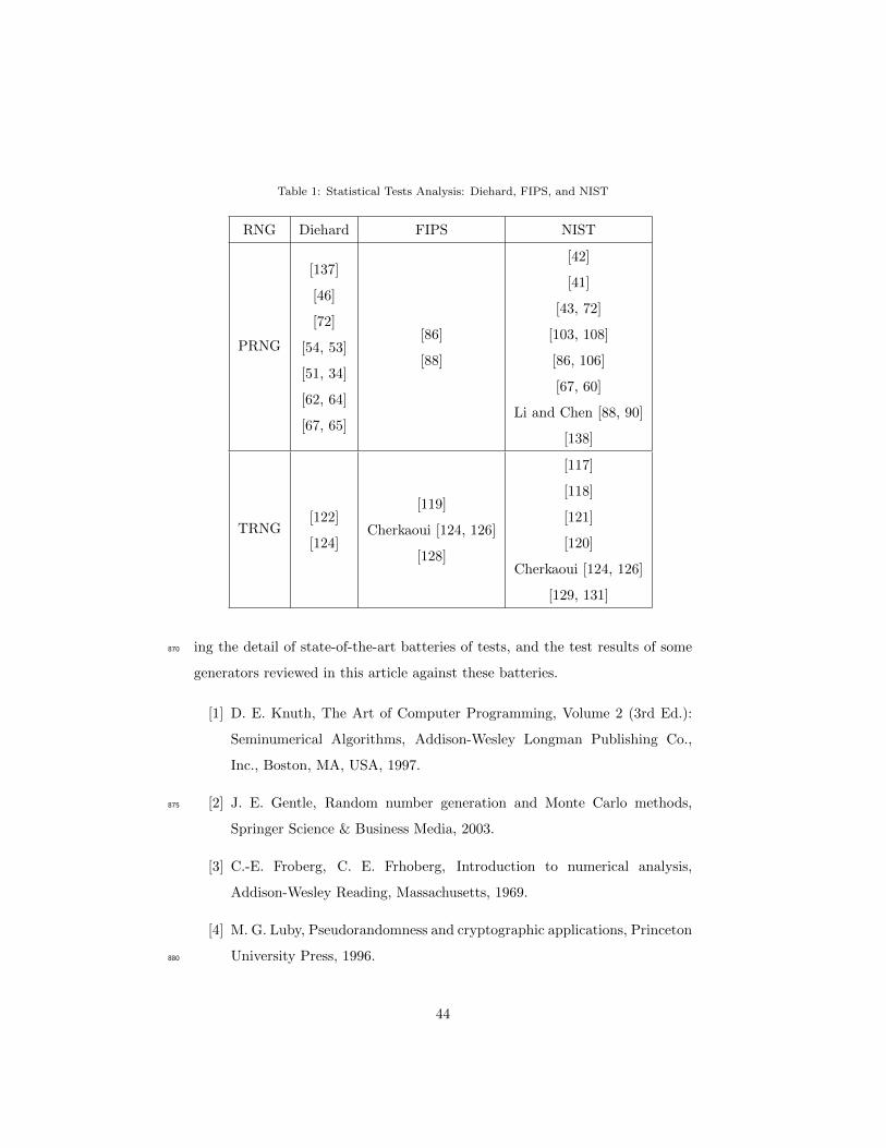
Table 1: Statistical Tests Analysis: Diehard, FIPS, and NIST
RNG Diehard FIPS NIST
PRNG
[137]
[46]
[72]
[54, 53]
[51, 34]
[62, 64]
[67, 65]
[86]
[88]
[42]
[41]
[43, 72]
[103, 108]
[86, 106]
[67, 60]
Li and Chen [88, 90]
[138]
TRNG[122]
[124]
[119]
Cherkaoui [124, 126]
[128]
[117]
[118]
[121]
[120]
Cherkaoui [124, 126]
[129, 131]
ing the detail of state-of-the-art batteries of tests, and the test results of some870
generators reviewed in this article against these batteries.
[1] D. E. Knuth, The Art of Computer Programming, Volume 2 (3rd Ed.):
Seminumerical Algorithms, Addison-Wesley Longman Publishing Co.,
Inc., Boston, MA, USA, 1997.
[2] J. E. Gentle, Random number generation and Monte Carlo methods,875
Springer Science & Business Media, 2003.
[3] C.-E. Froberg, C. E. Frhoberg, Introduction to numerical analysis,
Addison-Wesley Reading, Massachusetts, 1969.
[4] M. G. Luby, Pseudorandomness and cryptographic applications, Princeton
University Press, 1996.880
44
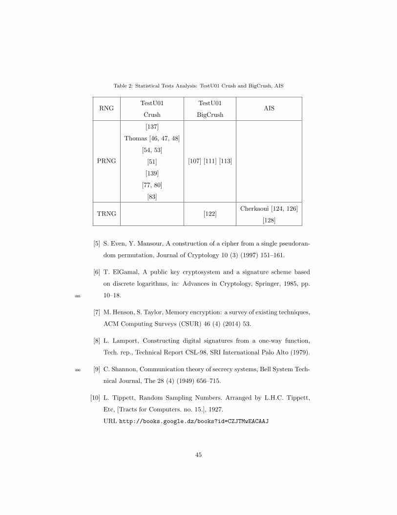
Table 2: Statistical Tests Analysis: TestU01 Crush and BigCrush, AIS
RNGTestU01
Crush
TestU01
BigCrushAIS
PRNG
[137]
Thomas [46, 47, 48]
[54, 53]
[51]
[139]
[77, 80]
[83]
[107] [111] [113]
TRNG [122]Cherkaoui [124, 126]
[128]
[5] S. Even, Y. Mansour, A construction of a cipher from a single pseudoran-
dom permutation, Journal of Cryptology 10 (3) (1997) 151–161.
[6] T. ElGamal, A public key cryptosystem and a signature scheme based
on discrete logarithms, in: Advances in Cryptology, Springer, 1985, pp.
10–18.885
[7] M. Henson, S. Taylor, Memory encryption: a survey of existing techniques,
ACM Computing Surveys (CSUR) 46 (4) (2014) 53.
[8] L. Lamport, Constructing digital signatures from a one-way function,
Tech. rep., Technical Report CSL-98, SRI International Palo Alto (1979).
[9] C. Shannon, Communication theory of secrecy systems, Bell System Tech-890
nical Journal, The 28 (4) (1949) 656–715.
[10] L. Tippett, Random Sampling Numbers. Arranged by L.H.C. Tippett,
Etc, [Tracts for Computers. no. 15.], 1927.
URL http://books.google.dz/books?id=CZJTMwEACAAJ
45
[11] M. Campbell-Kelly, M. Croarken, R. Flood, E. Robson, The history of895
mathematical tables, AMC 10 (2005) 12.
[12] M. G. Kendall, B. B. Smith, Randomness and random sampling numbers,
Journal of the royal Statistical Society (1938) 147–166.
[13] S. H. Lavington, A history of Manchester computers, NCC Publications,
1975.900
[14] G. W. Brown, History of rand’s random digits, summary, Tech. rep., DTIC
Document (1949).
[15] W. Thomson, Ernie–a mathematical and statistical analysis, Journal of
the Royal Statistical Society. Series A (General) (1959) 301–333.
[16] N. Metropolis, The beginning of the monte carlo method, Los Alamos905
Science 15 (584) (1987) 125–130.
[17] H. Niederreiter, N.-C. R. C. on Random Number Generation, Random
number generation and quasi-Monte Carlo methods, Vol. 63, SIAM, 1992.
[18] P. L’Ecuyer, Uniform random number generation, Annals of Operations
Research 53 (1) (1994) 77–120.910
[19] C. D. Motchenbacher, J. A. Connelly, Low-noise electronic system design,
Wiley New York, 1993.
[20] L. Kleeman, A. Cantoni, Metastable behavior in digital systems, Design
& Test of Computers, IEEE 4 (6) (1987) 4–19.
[21] G.-C. Hsieh, J. C. Hung, Phase-locked loop techniques. a survey, Industrial915
Electronics, IEEE Transactions on 43 (6) (1996) 609–615.
[22] R. H. Freeman, H.-C. Hsieh, Distributed memory architecture for a con-
figurable logic array and method for using distributed memory, uS Patent
5,343,406 (Aug. 30 1994).
46
[23] P. M. Freidin, Logic block with look-up table for configuration and mem-920
ory, uS Patent 5,414,377 (May 9 1995).
[24] E. Barker, A. Roginsky, Draft NIST special publication 800-131 recom-
mendation for the transitioning of cryptographic algorithms and key sizes
(2010).
[25] G. Marsaglia, The diehard test suite, 1995, URL http://stat. fsu. edu/˜925
geo/diehard. html.
[26] P. L’Ecuyer, R. Simard, Testu01: Ac library for empirical testing of ran-
dom number generators, ACM Transactions on Mathematical Software
(TOMS) 33 (4) (2007) 22.
[27] P. L’Ecuyer, F. Panneton, Fast random number generators based on linear930
recurrences modulo 2: overview and comparison, in: Proceedings of the
Winter Simulation Conference, 2005., 2005, pp. 10 pp.–.
[28] M. Matsumoto, T. Nishimura, Mersenne twister: a 623-dimensionally
equidistributed uniform pseudo-random number generator, ACM Trans-
actions on Modeling and Computer Simulation (TOMACS) 8 (1) (1998)935
3–30.
[29] R. C. Tausworthe, Random numbers generated by linear recurrence mod-
ulo two, Mathematics of Computation 19 (90) (1965) 201–209.
[30] D. E. Knuth, Deciphering a linear congruential encryption, IEEE Trans-
actions on Information Theory 31 (1) (1985) 49–52.940
[31] T. G. Lewis, W. H. Payne, Generalized feedback shift register pseudo-
random number algorithm, Journal of the ACM (JACM) 20 (3) (1973)
456–468.
[32] M. Matsumoto, Y. Kurita, Twisted gfsr generators, ACM Transactions on
Modeling and Computer Simulation (TOMACS) 2 (3) (1992) 179–194.945
47
[33] G. S. Fishman, L. R. Moore, III, An exhaustive analysis of multiplica-
tive congruential random number generators with modulus 2ˆ31-1, SIAM
Journal on Scientific and Statistical Computing 7 (1) (1986) 24–45.
[34] S. Banks, P. Beadling, A. Ferencz, Fpga implementation of pseudo random
number generators for monte carlo methods in quantitative finance, in:950
Reconfigurable Computing and FPGAs, 2008. ReConFig’08. International
Conference on, IEEE, 2008, pp. 271–276.
[35] W. H. Press, Numerical recipes 3rd edition: The art of scientific comput-
ing, Cambridge university press, 2007.
[36] G. Marsaglia, et al., Xorshift rngs, Journal of Statistical Software 8 (14)955
(2003) 1–6.
[37] G. Marsaglia, A. Zaman, A new class of random number generators, The
Annals of Applied Probability (1991) 462–480.
[38] A. K. Oudjida, N. Chaillet, Radix- 2r arithmetic for multiplication by a
constant, IEEE Transactions on Circuits and Systems II: Express Briefs960
61 (5) (2014) 349–353.
[39] A. K. Oudjida, A. Liacha, M. Bakiri, N. Chaillet, Multiple constant mul-
tiplication algorithm for high-speed and low-power design, IEEE Trans-
actions on Circuits and Systems II: Express Briefs 63 (2) (2016) 176–180.
[40] A. K. Oudjida, N. Chaillet, M. L. Berrandjia, Radix-2r arithmetic for965
multiplication by a constant: Further results and improvements, IEEE
Transactions on Circuits and Systems II: Express Briefs 62 (4) (2015)
372–376.
[41] R. S. Katti, S. K. Srinivasan, Efficient hardware implementation of a new
pseudo-random bit sequence generator, in: Circuits and Systems, 2009.970
ISCAS 2009. IEEE International Symposium on, IEEE, 2009, pp. 1393–
1396.
48
[42] E. Erkek, T. Tuncer, The implementation of asg and sg random number
generators, in: System Science and Engineering (ICSSE), 2013 Interna-
tional Conference on, 2013, pp. 363–367.975
[43] V. R. Gonzalez-Diaz, F. Pareschi, G. Setti, F. Maloberti, A pseudorandom
number generator based on time-variant recursion of accumulators, Cir-
cuits and Systems II: Express Briefs, IEEE Transactions on 58 (9) (2011)
580–584.
[44] V. Friedman, The structure of the limit cycles in sigma delta modulation,980
Communications, IEEE Transactions on 36 (8) (1988) 972–979.
[45] F. Maloberti, E. Bonizzoni, A. Surano, Time variant digital sigma-delta
modulator for fractional-n frequency synthesizers, in: Radio-Frequency
Integration Technology, 2009. RFIT 2009. IEEE International Symposium
on, IEEE, 2009, pp. 111–114.985
[46] D. B. Thomas, W. Luk, Fpga-optimised high-quality uniform ran-
dom number generators, in: Proceedings of the 16th international
ACM/SIGDA symposium on Field programmable gate arrays, ACM,
2008, pp. 235–244.
[47] D. B. Thomas, W. Luk, Fpga-optimised uniform random number gener-990
ators using luts and shift registers, in: Field Programmable Logic and
Applications (FPL), 2010 International Conference on, IEEE, 2010, pp.
77–82.
[48] D. B. Thomas, W. Luk, The lut-sr family of uniform random number
generators for fpga architectures, Very Large Scale Integration (VLSI)995
Systems, IEEE Transactions on 21 (4) (2013) 761–770.
[49] S. Chandrasekaran, A. Amira, High performance fpga implementation of
the mersenne twister, in: Electronic Design, Test and Applications, 2008.
DELTA 2008. 4th IEEE International Symposium on, IEEE, 2008, pp.
482–485.1000
49
[50] X. Tian, K. Benkrid, Mersenne twister random number generation on
fpga, cpu and gpu, in: Adaptive Hardware and Systems, 2009. AHS 2009.
NASA/ESA Conference on, IEEE, 2009, pp. 460–464.
[51] I. L. Dalal, J. Harwayne-Gidansky, D. Stefan, On the fast generation of
long-period pseudorandom number sequences, in: Systems, Applications1005
and Technology Conference, 2008 IEEE Long Island, IEEE, 2008, pp. 1–9.
[52] M. Saito, M. Matsumoto, Simd-oriented fast mersenne twister: a 128-
bit pseudorandom number generator, in: Monte Carlo and Quasi-Monte
Carlo Methods 2006, Springer, 2008, pp. 607–622.
[53] Y. Li, J. Jiang, H. Cheng, M. Zhang, S. Wei, An efficient hardware random1010
number generator based on the mt method, in: Computer and Information
Technology (CIT), 2012 IEEE 12th International Conference on, IEEE,
2012, pp. 1011–1015.
[54] S. Wu, J. Jiang, Y. Fu, Hardware architecture for the parallel generation of
long-period random numbers using mt method, in: Computer Engineering1015
and Technology, Springer, 2013, pp. 8–15.
[55] P. Echeverrıa, M. Lopez-Vallejo, High performance fpga-oriented
mersenne twister uniform random number generator, Journal of Signal
Processing Systems 71 (2) (2013) 105–109.
[56] J. Von Neumann, A. W. Burks, et al., Theory of self-reproducing au-1020
tomata, IEEE Transactions on Neural Networks 5 (1) (1966) 3–14.
[57] J. Gleick, Chaos: Making a new science, Random House, 1997.
[58] P. Anghelescu, E. Sofron, S. Ionita, Vlsi implementation of high-speed
cellular automata encryption algorithm, in: Semiconductor Conference,
2007. CAS 2007. International, Vol. 2, IEEE, 2007, pp. 509–512.1025
[59] I. Dogaru, R. Dogaru, Algebraic normal form for rapid prototyping of
elementary hybrid cellular automata in fpga, in: Electrical and Electronics
50
Engineering (ISEEE), 2010 3rd International Symposium on, IEEE, 2010,
pp. 277–280.
[60] D. Ioana, D. Radu, Fpga implementation and evaluation of two cryp-1030
tographically secure hybrid cellular automata, in: Communications
(COMM), 2014 10th International Conference on, IEEE, 2014, pp. 1–4.
[61] T. E. Tkacik, A hardware random number generator, in: Cryptographic
Hardware and Embedded Systems-CHES 2002, Springer, 2003, pp. 450–
453.1035
[62] J. C. Cerda, C. D. Martinez, J. M. Comer, D. H. Hoe, An efficient fpga
random number generator using lfsrs and cellular automata, in: Circuits
and Systems (MWSCAS), 2012 IEEE 55th International Midwest Sym-
posium on, IEEE, 2012, pp. 912–915.
[63] S.-U. Guan, S. K. Tan, Pseudorandom number generator–the self pro-1040
grammable cellular automata, in: Knowledge-Based Intelligent Informa-
tion and Engineering Systems, Springer, 2003, pp. 1230–1235.
[64] J. M. Comer, J. C. Cerda, C. D. Martinez, D. H. Hoe, Random num-
ber generators using cellular automata implemented on fpgas, in: System
Theory (SSST), 2012 44th Southeastern Symposium on, IEEE, 2012, pp.1045
67–72.
[65] L. Raut, D. H. Hoe, Stream cipher design using cellular automata im-
plemented on fpgas, in: System Theory (SSST), 2013 45th Southeastern
Symposium on, IEEE, 2013, pp. 146–149.
[66] M. David, D. C. Ranasinghe, T. Larsen, A2u2: a stream cipher for printed1050
electronics rfid tags, in: RFID (RFID), 2011 IEEE International Confer-
ence on, IEEE, 2011, pp. 176–183.
[67] L. Kotoulas, D. Tsarouchis, G. C. Sirakoulis, I. Andreadis, 1-d cellular
automaton for pseudorandom number generation and its reconfigurable
51

hardware implementation, in: Circuits and Systems, 2006. ISCAS 2006.1055
Proceedings. 2006 IEEE International Symposium on, IEEE, 2006, pp.
4–pp.
[68] L. Blum, M. Blum, M. Shub, A simple unpredictable pseudo-random num-
ber generator, SIAM Journal on computing 15 (2) (1986) 364–383.
[69] K. Sewak, P. Rajput, A. K. Panda, Fpga implementation of 16 bit bbs and1060
lfsr pn sequence generator: A comparative study, in: Electrical, Electron-
ics and Computer Science (SCEECS), 2012 IEEE Students’ Conference
on, IEEE, 2012, pp. 1–3.
[70] P. Peris-Lopez, E. San Millan, J. C. van der Lubbe, L. A. Entrena, Crypto-
graphically secure pseudo-random bit generator for rfid tags, in: Internet1065
Technology and Secured Transactions (ICITST), 2010 International Con-
ference for, IEEE, 2010, pp. 1–6.
[71] P. L. Montgomery, Modular multiplication without trial division, Mathe-
matics of computation 44 (170) (1985) 519–521.
[72] K. H. Tsoi, K. Leung, P. H. W. Leong, Compact fpga-based true and1070
pseudo random number generators, in: Field-Programmable Custom
Computing Machines, 2003. FCCM 2003. 11th Annual IEEE Symposium
on, IEEE, 2003, pp. 51–61.
[73] L. M. Pecora, T. L. Carroll, Synchronization in chaotic systems, Physical
review letters 64 (8) (1990) 821.1075
[74] S. Wiggins, Introduction to applied nonlinear dynamical systems and
chaos, Vol. 2, Springer Science & Business Media, 2003.
[75] R. M. May, et al., Simple mathematical models with very complicated
dynamics, Nature 261 (5560) (1976) 459–467.
[76] M. Henon, A two-dimensional mapping with a strange attractor, Commu-1080
nications in Mathematical Physics 50 (1) (1976) 69–77.
52
[77] P. Dabal, R. Pelka, A chaos-based pseudo-random bit generator imple-
mented in fpga device, in: Design and Diagnostics of Electronic Circuits &
Systems (DDECS), 2011 IEEE 14th International Symposium on, IEEE,
2011, pp. 151–154.1085
[78] W. Padgett, D. Anderson, Fixed-Point Signal Processing, Synthesis lec-
tures on signal processing, Morgan & Claypool, 2009.
URL http://books.google.dz/books?id=h590cd_BagMC
[79] P. Dabal, R. Pelka, Fpga implementation of chaotic pseudo-random
bit generators, in: Mixed Design of Integrated Circuits and Systems1090
(MIXDES), 2012 Proceedings of the 19th International Conference, IEEE,
2012, pp. 260–264.
[80] P. Dabal, R. Pelka, A study on fast pipelined pseudo-random number
generator based on chaotic logistic map, in: Design and Diagnostics of
Electronic Circuits Systems, 17th International Symposium on, 2014, pp.1095
195–200.
[81] A. Pande, J. Zambreno, Design and hardware implementation of a chaotic
encryption scheme for real-time embedded systems, in: Signal Processing
and Communications (SPCOM), 2010 International Conference on, IEEE,
2010, pp. 1–5.1100
[82] S. Liu, J. Sun, Z. Xu, Z. Cai, An improved chaos-based stream cipher
algorithm and its vlsi implementation, in: Networked Computing and
Advanced Information Management, 2008. NCM’08. Fourth International
Conference on, Vol. 2, IEEE, 2008, pp. 191–197.
[83] L. Merah, A. ALI-PACHA, N. H. SAID, Coupling two chaotic systems in1105
order to increasing the security of a communication system-study and real
time fpga implementation.
[84] P. Giard, G. Kaddoum, F. Gagnon, C. Thibeault, Fpga implementation
and evaluation of discrete-time chaotic generators circuits, in: IECON
53
2012-38th Annual Conference on IEEE Industrial Electronics Society,1110
IEEE, 2012, pp. 3221–3224.
[85] T. Geisel, V. Fairen, Statistical properties of chaos in chebyshev maps,
Physics Letters A 105 (6) (1984) 263–266.
[86] Y. Mao, L. Cao, W. Liu, Design and fpga implementation of a pseudo-
random bit sequence generator using spatiotemporal chaos, in: Communi-1115
cations, Circuits and Systems Proceedings, 2006 International Conference
on, Vol. 3, IEEE, 2006, pp. 2114–2118.
[87] J. Cernak, Digital generators of chaos, Physics letters A 214 (3) (1996)
151–160.
[88] C.-Y. Li, J.-S. Chen, T.-Y. Chang, A chaos-based pseudo random number1120
generator using timing-based reseeding method, in: Circuits and Systems,
2006. ISCAS 2006. Proceedings. 2006 IEEE International Symposium on,
IEEE, 2006, pp. 4–pp.
[89] R. B, Simultaneous carry adder, uS Patent 2,966,305 (Dec. 27 1960).
URL http://www.google.com/patents/US29663051125
[90] C.-Y. Li, Y.-H. Chen, T.-Y. Chang, L.-Y. Deng, K. To, Period extension
and randomness enhancement using high-throughput reseeding-mixing
prng, Very Large Scale Integration (VLSI) Systems, IEEE Transactions
on 20 (2) (2012) 385–389.
[91] L.-Y. Deng, Efficient and portable multiple recursive generators of1130
large order, ACM Transactions on Modeling and Computer Simulation
(TOMACS) 15 (1) (2005) 1–13.
[92] T. Oshiba, Closure property of family of context-free languages un-
der cyclic shift operation, ELECTRONICS & COMMUNICATIONS IN
JAPAN 55 (4) (1972) 119–122.1135
54

[93] J. J. Shedletsky, Comment on the sequential and indeterminate behavior
of an end-around-carry adder, IEEE Transactions on Computers 26 (3)
(1977) 271–272.
[94] N. Hariprasad, et al., Fpga implementation of a cryptography technol-
ogy using pseudo random number generator, in: International Journal of1140
Engineering Research and Technology, Vol. 2, ESRSA Publications, 2013.
[95] O. Rssler, An equation for continuous chaos, Physics Letters A 57 (5)
(1976) 397 – 398.
URL http://www.sciencedirect.com/science/article/pii/
03759601769010181145
[96] A. S. Elwakil, M. P. Kennedy, Construction of classes of circuit-
independent chaotic oscillators using passive-only nonlinear devices, Cir-
cuits and Systems I: Fundamental Theory and Applications, IEEE Trans-
actions on 48 (3) (2001) 289–307.
[97] A. Elwakil, M. Kennedy, Chaotic oscillator configuration using a frequency1150
dependent negative resistor, International journal of circuit theory and
applications 28 (1) (2000) 69–76.
[98] M. A. Zidan, A. G. Radwan, K. N. Salama, The effect of numerical tech-
niques on differential equation based chaotic generators, in: Microelec-
tronics (ICM), 2011 International Conference on, IEEE, 2011, pp. 1–4.1155
[99] G. Chen, J. Lu, Dynamics of the lorenz system family: analysis, control
and synchronization, SciencePress, Beijing.
[100] P. Tsai, C. Merkle, T. Huang, Euler equation analysis of the propeller-
wake interaction, in: Symposium on Naval Hydrodynamics, 17th, 1900.
[101] P. C. Hammer, The midpoint method of numerical integration, Mathe-1160
matics Magazine 31 (4) (1958) 193–195.
55
[102] J. C. Butcher, Numerical methods for ordinary differential equations in
the 20th century, Journal of Computational and Applied Mathematics
125 (1) (2000) 1–29.
[103] M. A. Zidan, A. G. Radwan, K. N. Salama, Random number generation1165
based on digital differential chaos, in: Circuits and Systems (MWSCAS),
2011 IEEE 54th International Midwest Symposium on, IEEE, 2011, pp.
1–4.
[104] E. G, Latched carry save adder circuit for multipliers, uS Patent 3,340,388
(Sep. 5 1967).1170
URL http://www.google.com/patents/US3340388
[105] C. S. Wallace, A suggestion for a fast multiplier, Electronic Computers,
IEEE Transactions on (1) (1964) 14–17.
[106] A. S. Mansingka, M. L. Barakat, M. A. Zidan, A. G. Radwan, K. N.
Salama, Fibonacci-based hardware post-processing for non-autonomous1175
signum hyperchaotic system, in: IT Convergence and Security (ICITCS),
2013 International Conference on, IEEE, 2013, pp. 1–4.
[107] X. Fang, Q. Wang, C. Guyeux, J. M. Bahi, Fpga acceleration of a pseu-
dorandom number generator based on chaotic iterations, Journal of Infor-
mation Security and Applications 19 (1) (2014) 78–87.1180
[108] J. M. Bahi, X. Fang, C. Guyeux, L. Larger, Fpga design for pseudorandom
number generator based on chaotic iteration used in information hiding
application, Appl. Math 7 (6) (2013) 2175–2188.
[109] Q. Wang, S. Yu, C. Guyeux, J. Bahi, X. Fang, Study on a new chaotic
bitwise dynamical system and its FPGA implementation, Chinese Physics1185
B 24 (6) (2015) 060503.
URL http://dx.doi.org/10.1088/1674-1056/24/6/060503
[110] Q. Wang, S. Yu, C. Guyeux, J. Bahi, X. Fang, A chaotic bitwise dynam-
ical system and its FPGA-based realization, in: IWCFTA1’4, 7-th Int.
56
Workshop on Chaos-Fractals Theories and Applications, Qingdao, China,1190
2014, pp. ***–***.
[111] M. Bakiri, J.-F. Couchot, C. Guyeux, Fpga implementation of f2-linear
pseudorandom number generators based on zynq mpsoc: A chaotic itera-
tions post processing case study, in: Proceedings of the 13th International
Joint Conference on e-Business and Telecommunications - Volume 4: SE-1195
CRYPT,, 2016, pp. 302–309.
[112] M. Bakiri, J. F. Couchot, C. Guyeux, Ciprng: A vlsi family of chaotic
iterations post-processings for f-2 linear pseudorandom number genera-
tion based on zynq mpsoc, IEEE Transactions on Circuits and Systems I:
Regular Papers PP (99) (2017) 1–14.1200
[113] M. Bakiri, J.-F. Couchot, C. Guyeux, One random jump and one permu-
tation: Sufficient conditions to chaotic, statistically faultless, and large
throughput prng for fpga, in: Proceedings of the 14th International
Joint Conference on e-Business and Telecommunications - Volume 6: SE-
CRYPT, (ICETE 2017), INSTICC, SciTePress, 2017, pp. 295–302.1205
[114] J.-F. Couchot, P.-C. Heam, C. Guyeux, Q. Wang, J. M. Bahi, Pseudo-
random number generators with balanced gray codes, in: Security and
Cryptography (SECRYPT), 2014 11th International Conference on, IEEE,
2014, pp. 1–7.
[115] S. Contassot-Vivier, J.-F. Couchot, C. Guyeux, P.-C. Heam, Random walk1210
in a n-cube without hamiltonian cycle to chaotic pseudorandom number
generation: Theoretical and practical considerations, International Jour-
nal of Bifurcation and Chaos 27 (01) (2017) 1750014.
[116] B. B. Purkayastha, K. K. Sarma, Digital phase-locked loop, in: A Dig-
ital Phase Locked Loop based Signal and Symbol Recovery System for1215
Wireless Channel, Springer, 2015, pp. 103–126.
57

[117] V. Fischer, M. Drutarovsky, True random number generator embedded
in reconfigurable hardware, in: Cryptographic Hardware and Embedded
Systems-CHES 2002, Springer, 2003, pp. 415–430.
[118] M. Simka, M. Drutarovsky, V. Fischer, Embedded true random number1220
generator in actel fpgas, in: Workshop on Cryptographic Advances in
Secure Hardware–CRASH, 2005, pp. 6–7.
[119] M. Simka, M. Drutarovsky, V. Fischer, et al., Testing of pll-based true
random number generator in changingworking conditions, RADIOENGI-
NEERING, 20 (2011) 94–101.1225
[120] M. Varchola, M. Drutarovsky, R. Fouquet, V. Fischer, Hardware plat-
form for testing performance of trngs embedded in actel fusion fpga, in:
Radioelektronika, 2008 18th International Conference, IEEE, 2008, pp.
1–4.
[121] P. Kohlbrenner, K. Gaj, An embedded true random number generator1230
for fpgas, in: Proceedings of the 2004 ACM/SIGDA 12th international
symposium on Field programmable gate arrays, ACM, 2004, pp. 71–78.
[122] C. Klein, O. Cret, A. Suciu, Design and implementation of a high quality
and high throughput trng in fpga, arXiv preprint arXiv:0906.4762.
[123] M. Dichtl, J. D. Golic, High-speed true random number generation with1235
logic gates only, Springer, 2007.
[124] A. Cherkaoui, V. Fischer, A. Aubert, L. Fesquet, A self-timed ring based
true random number generator, in: Asynchronous Circuits and Systems
(ASYNC), 2013 IEEE 19th International Symposium on, IEEE, 2013, pp.
99–106.1240
[125] A. Cherkaoui, V. Fischer, A. Aubert, L. Fesquet, Comparison of self-timed
ring and inverter ring oscillators as entropy sources in fpgas, in: Design,
Automation & Test in Europe Conference & Exhibition (DATE), 2012,
IEEE, 2012, pp. 1325–1330.
58
[126] A. Cherkaoui, V. Fischer, L. Fesquet, A. Aubert, A very high speed true1245
random number generator with entropy assessment, in: Cryptographic
Hardware and Embedded Systems-CHES 2013, Springer, 2013, pp. 179–
196.
[127] I. E. Sutherland, Micropipelines, Communications of the ACM 32 (6)
(1989) 720–738.1250
[128] I. Vasyltsov, E. Hambardzumyan, Y.-S. Kim, B. Karpinskyy, Fast digital
trng based on metastable ring oscillator, in: Cryptographic Hardware and
Embedded Systems–CHES 2008, Springer, 2008, pp. 164–180.
[129] M. Majzoobi, F. Koushanfar, S. Devadas, Fpga-based true random num-
ber generation using circuit metastability with adaptive feedback con-1255
trol, in: Cryptographic Hardware and Embedded Systems–CHES 2011,
Springer, 2011, pp. 17–32.
[130] E. Salman, A. Dasdan, F. Taraporevala, K. Kucukcakar, E. G. Fried-
man, Exploiting setup–hold-time interdependence in static timing anal-
ysis, Computer-Aided Design of Integrated Circuits and Systems, IEEE1260
Transactions on 26 (6) (2007) 1114–1125.
[131] D. Lee, H. Seo, H. Kim, Metastability-based feedback method for enhanc-
ing fpga-based trng., International Journal of Multimedia & Ubiquitous
Engineering 9 (3).
[132] NIST, National institute of standards and technology (nist): Fips140− 1:1265
Security requirements for cryptographic modules @ONLINE (1994).
URL csrc.nist.gov/publications/fips/fips140-1/fips1401.pdf
[133] NIST, National institute of standards and technology (nist): A statistical
test suite for random and pseudorandom number generators for crypto-
graphic applications @ONLINE (2010).1270
URL csrc.nist.gov/publications/nistpubs/800-22-rev1a/
SP800-22rev1a.pdf
59

[134] W. Killmann, W. Schindler, A proposal for: Functionality classes and
evaluation methodology for true (physical) random number generators, T-
Systems debis Systemhaus Information Security Services and Bundesamt1275
fur Sicherheit in der Informationstechnik (BSI), Tech. Rep.
[135] NIST, National institute of standards and technology (nist): Fips140− 2:
Security requirements for cryptographic modules @ONLINE (May 2001).
URL csrc.nist.gov/publications/fips/fips140-2/fips1402.pdf
[136] A. Canteaut, Berlekamp–massey algorithm, in: Encyclopedia of Cryptog-1280
raphy and Security, Springer, 2011, pp. 80–80.
[137] I. Zarei Moghadam, A. S. Rostami, M. R. Tanhatalab, Designing a ran-
dom number generator with novel parallel lfsr substructure for key stream
ciphers, in: Computer Design and Applications (ICCDA), 2010 Interna-
tional Conference on, Vol. 5, IEEE, 2010, pp. V5–598.1285
[138] Z. Zhu, H. Hu, A dynamic nonlinear transform arithmetic for improving
the properties chaos-based prng, in: Intelligent Control and Automation
(WCICA), 2010 8th World Congress on, 2010, pp. 7055–7060.
[139] V. Bonato, B. F. Mazzotti, M. M. Fernandes, E. Marques, A mersenne
twister hardware implementation for the monte carlo localization algo-1290
rithm, Journal of Signal Processing Systems 70 (1) (2013) 75–85.
60