Embed Size (px)
Citation preview

0
Survey of Facilities Space Division
TN-TR-1000, Issue 20, May 2016
Main Building Complex of the Space Test Centre
IABG Industrieanlagen-Betriebsgesellschaft mbH
Einsteinstrasse 20, 85521 Ottobrunn, Germany, Phone 089 6088-0

29
General Point of Contact Mr. C. Henjes Phone +49 89 6088 - 4080 or - 3514 Fax - 3194 e-mail: [email protected]
Test Preparation Hall and Checkout Rooms 9 Your Point of Contact: Mr. U. Zaske Phone +49 89 6088 - 2702 or - 3703 Fax - 2657 e-mail: [email protected]
Space Simulation / Thermal Vacuum Facilities 13 Your Point of Contact: Mr. Alwin Eisenmann Phone +49 89 6088 - 2275 or - 2228 Fax - 4060 e-mail: [email protected]
Vibration Test Facilities 19 Your Point of Contact: Mr. R. Baumgartl Phone +49 89 6088 - 3506 or - 2297 Fax - 4060 e-mail: [email protected]
Modal Test Facilities 26 Your Point of Contact: Dr. A. Grillenbeck Phone +49 89 6088 - 3909 or - 2703 Fax - 3964 e-mail: [email protected]
Acoustic Test Facilities 32 Your Point of Contact: Dr. A. Grillenbeck Phone +49 89 6088 - 3909 or - 2703 Fax - 3964 e-mail: [email protected]
Electromagnetic Compatibility Test Facility 37 Your Point of Contact: Mr. A. Grielhüsl Phone +49 89 6088 - 2179 or - 2619 Fax - 3970 e-mail: [email protected]
Magnetic Test Facilities 46 Your Point of Contact: Mr. R. Lauxen Phone +49 89 6088 - 2693 or - 2619 Fax - 3970 e-mail: [email protected]

3
TN-TR-1000, Issue 20, May 2016
Mass Property Measurements 52 Your Point of Contact: Mr. T. Schwab Phone +49 89 6088 - 2170 or - 2703 Fax - 3964 e-mail: [email protected]
Calibration Facilities for Dynamic Motion Measuring Equipment 56 Your Point of Contact: Mr. T. Schwab Phone +49 89 6088 - 2170 or - 2703 Fax - 3964 e-mail: [email protected]
Calibration Facilities for Electric and Thermo-Electric Quantities 56 Your Point of Contact: Mr. K. Bayler Phone +49 89 6088 - 2827 or - 2619 Fax - 3970 e-mail: [email protected]

4
TN-TR-1000, Issue 20, May 2016
IABG operates the national space test centres at Ottobrunn near Munich, Ger-many. It is IABG’s daily business to per-form all kinds of tests as described below. All test facilities at IABG’s Space Division are combined under one roof and easily accessible, as can be seen from the ground plan (see Fig. 1). During many demanding tests on spacecraft and other specimen, IABG has proven to be most efficient and reliable. The Space Division includes facilities for: 1. Space Simulation /
Thermal Vacuum
Four thermal vacuum chambers with inner diameters of 6.2 m, 3.6 m, 2.5 m, and 2.1 m are available for thermal vacuum tests. The development and operation of a spacecraft require design and functional performances of a thermal control subsys-tem to ensure an adequate thermal envi-ronment for the various components on board. The design and the functional perfor-mance of the thermal subsystem and the complete spacecraft system are studied in thermal test facilities (also called heat bal-ance, space simulation or thermal vacuum facilities). Under simulated thermal space conditions, verification of the thermal model calcula-tion and qualification as well as ac-ceptance of the functional performance of the thermal control subsystem and the spacecraft system have to be achieved. The essential space conditions which are simulated in large thermal testing facilities are vacuum conditions, radiative heat sink, solar radiative input and thermal loads. A comprehensive data handling system is available for collection, computation and monitoring of measured test data. Another chamber available at the space simulation department is an Ambient Pressure Thermal Cycling test facility
(APTC) for specimen that do not require vacuum conditions for the test. 2. Vibration and Shock
The vibration laboratory is equipped with an electrodynamic multi-shaker system (force vector 320 kN) and a number of single shakers of different sizes. Some facilities are equipped with climatic cham-bers for combined vibration and thermal loading. The facilities are computer controlled and allow the simulation of sine, random, sine-on-random and transient excitation. A digi-tal data acquisition and processing system provides up to 250 channels for accelera-tion and 100 channels for strain and force measurements per facility in standard con-figuration. However, due to the communal-ity of the data acquisition with the modal and the acoustic facility, the maximum channel count for a test project is not lim-ited to these numbers and can even be extended up to 1,000 channels. Unique classical shock test machines as well as a dedicated tool for the simulation of pyroshock events round up the compre-hensive mechanical services. 3. Modal Testing
Modal testing is required to validate dy-namic mathematical models or to investi-gate the dynamic (operational) behaviour of structures in detail. A versatile mobile modal test system is available which incorporates the latest hardware and software technologies and which may be used for both small and large modal tests. The maximum channel count amounts up to 1,000 and may be incremented in steps of 126 channels. The complete system is mobile and may be used table top, smaller portions of it even in vehicles. The modal test system is

5
TN-TR-1000, Issue 20, May 2016
complemented by various excitation means including modal exciters rated 10 N up to 7 kN as well as a scanning laser vibrometer for contactless vibration meas-urements. Powerful software tools are used for test control and evaluation of the measured signals. The available comprehensive modal analysis tools enable customised solutions for even unconventional testing tasks in the sphere of aerospace and gen-eral engineering. 4. Acoustics Acoustic noise tests are performed in the reverberation chamber offering a volume of 1,378 m³ to qualify test objects against the acoustic environments up to 156 dB OASPL as encountered during the launch of a spacecraft. For re-entry and engine noise acoustic environments, equipment can be subjected to fluctuating pressure fields in a special Progressive Wave Tube up to 170 dB OASPL. Up to 256 response measurements can be taken during such tests and up to 24 microphones for the control and measurement of the noise field. The control of the acoustic noise field can be performed either manually or au-tomatically. 5. EMC
The EMC test facility consists of a large and two medium anechoic chambers, each with an anteroom for measurement equipment and customer EGSE. Frequen-cy domain emission tests can be per-formed with computer controlled EMI-receivers up to 40 GHz and time domain measurements with digital and analogue oscilloscopes up to 5 GS/s. Susceptibility test equipment allows to generate fields with more than 4,000 V/m and up to 40 GHz. Lightning; ESD, Power Simulation
and other time domain effects can be car-ried out. With the available test equipment and a unique infrastructure (power interfaces, clean room), complex test objects can be qualified both according to most EMC standard procedures and according to special customer requirements. 6. Magnetics
IABG’s Space Division has one of the most sophisticated magnetic test facilities in the world which is unique in Europe. Thanks to the facility, IABG covers a do-main not covered by standard EMC test facilities, i.e. the frequency range below 25 kHz down to DC. This enables custom-ers to test whether magnetometers func-tion properly in conjunction with other sci-entific instruments in the payload and with the spacecraft itself during different mag-netic conditions that are encountered dur-ing integration, testing, launch, and in or-bit. 7. Mass Property Measurements
For satellites, space probes, launcher parts, payloads, or for any kind of general engineering systems a complete set of facilities is available for the accurate de-termination of the mass properties. These measurements comprise the de-termination of mass (weight), centre of gravity (CoG), moment of inertia (MoI) and product of inertia (PoI). Furthermore static and dynamic balancing can be performed. Specimens can be handled from system level size of 2 metric tons (up to 4 metric tons beginning of 2012) down to subsys-tem level.

6
TN-TR-1000, Issue 20, May 2016
Ground Plan of the Space Test Centre

7
TN-TR-1000, Issue 20, May 2016
Location of the Space Test Centre
In connection with preparation halls and checkout rooms, with environmental sim-ulation facilities (climatic chambers, etc.), with static and dynamic test facilities even for large structures, with a material test laboratory at IABG, and with a compact
antenna / payload test range in the im-mediate vicinity (operated by Airbus DS GmbH), this centre offers an exceptional combination of test facilities for space applications.
Munich
Munich Airport
A 96 Lindau
A 95 Garmisch- Partenkirchen
A 8 Salzburg
A 99 Autobahnring Ost
A 99
Hbf. Ostbf.
Neuperlach Süd
A 8 Stuttgart
Ausfahrt Dachau
Exit Oberschleiß heim
Exit Flughafen- München
Exit Ottobrunn
Behelfs- ausfahrt
Mittlerer Ring
A 94 Passau
Junction München-Ost
Junction München-Nord
Junction Neufahrn
Junction
München-Brunnthal
A 92 Deggendorf
A 92
S 8
B 471
B 11
A 9 Nürnberg Regensburg
to Munich
to Salzburg
How to reach IABG in Ottobrunn:
Access by public transport:
From Munich Airport by rapid transit train line S8 till München-Ostbahnhof (cont. see from München-Ostbahnhof). From Munich Central Station (Hauptbahnhof) by rapid transit train lines S1, S2, S3, S4, S6, S7 and S8 till München-Ostbahnhof (cont. see from München- Ostbahnhof) or by rapid transit train line S7 till Neuperlach Süd (cont. see from Neuperlach-Süd) or till Ottobrunn (cont. see from Ottobrunn) or by subway line U5 till München-Ostbahnhof (cont. see from München-Ostbahnhof) or till Neuperlach-Süd (cont. see from Neuperlach-Süd). From München-Ostbahnhof by bus line 213 till stop Taufkirchen Willy-Messerschmitt-Straße or till stop Taufkirchen Lilienthalstraße or by rapid transit train line S7 till Neuperlach-Süd (cont. see from Neuperlach-Süd) or till Ottobrunn (cont. see from Ottobrunn) or by subway line U5 till Neuperlach-Süd (cont. see from Neuperlach-Süd) rapid transit train or subway. From Neuperlach-Süd by bus line 210 till stop Ottobrunn Einsteinstraße or by bus line 222 till stop Taufkirchen Lilienthalstraße. From Ottobrunn station by bus line 241 till stop Taufkirchen Lilienthalstraße or by bus line 214 till stop Ottobrunn Einsteinstraße From bus stops Taufkirchen Willy-Messerschmitt-Straße, Taufkirchen Lilienthalstraße and Ottobrunn Einsteinstraße you will reach IABG within a few minutes (see also site plan). Please find out about details concerning departure times of Munich‘s public transport U5 / Bus 210: every 10 minutes • S7 / Bus 241: every 20 minutes Bus 213 / 222: at rush hours every 10 or 30 minutes Bus 214: every 60 minutes • at rush hours every 20 or 40 minutes All timetables of Munich public transport facilities are available under www.mvv-muenchen.de/en/homepage/index.html

8
TN-TR-1000, Issue 20, May 2016
Access by road:
From direction Munich Airport (A 92) at junction Neufahrn onto A 9 direction Salzburg and at junction München-Nord onto A 99, direction Salzburg till exit Ottobrunn (cont. see from Ottobrunn). From direction München-Zentrum (A 8) direction Salzburg till exit Taufkirchen-Ost (cont. see from Taufkirchen-Ost). From direction Nürnberg (A 9) and Regensburg (A 93 / A 9) at junction München-Nord onto A 99 direction Salzburg till exit Ottobrunn (cont. see from Ottobrunn). From direction Stuttgart (A 8) at junction München-Eschenried onto A 99 till exit Ottobrunn (cont. see from Ottobrunn). From direction Rosenheim / Salzburg (A 8) till exit Taufkirchen-Ost (cont. see from Taufkirchen-Ost). From direction Lindau (A 96) / Garmisch (A 95) via “mittlerer Ring Süd” direction Salzburg onto A 995. At junction München-Süd follow the signposting Nürnberg (A 99) M-Ramersdorf. Via exit M-Ramersdorf onto A 8 exit Taufkirchen-Ost (continuing from Taufkirchen-Ost). Alternatively from direction Lindau (A 96) at junction München-Südwest onto A 99 West, A 99 Ost till exit Ottobrunn (cont. see from Ottobrunn). From direction Passau (A 94) at junction München-Ost onto A 99 direction Salzburg till exit Ottobrunn (cont. see from Ottobrunn). From exit Taufkirchen-Ost please follow the signposting “Gewerbegebiet Taufkirchen-Ost II” (B 471) and turn off at signposting “Taufkirchen-Ost II / Airbus Group” (2nd road to the left, Willy-Messerschmitt-Str.). So you drive directly towards IABG. From exit Ottobrunn please continue direction Ottobrunn / München till the next intersection (traffi c light). Here turn to the left direction Unterhaching / Taufkirchen onto B 471. Please leave the B 471 at the signposting Taufkirchen I / IABG on the right hand side. INFORMATION FOR USERS OF NAVIGATION SYSTEMS Please enter the following destination: Lilienthalstr. 12 • 85521 Taufkirchen bei München
Fig. 3: Site Plan of IABG

9
TN-TR-1000, Issue 20, May 2016
Space Division Test Preparation and Checkout Rooms
Test Preparation Hall with Tandem-X, CryoSat 2 and Ariane 5+ ESC-A upper stage

10
TN-TR-1000, Issue 20, May 2016
1. Summary
Adjacent to each space test facility, there are preparation areas for the specific preparations of the test objects. In addi-tion, general preparation areas are avail-able for the customer, with nearby
checkout rooms which are provided with cable links to the individual test facilities. Also available are customers offices and storage areas.
2. Description and Data
Fig. shows the location of the test prepa-ration halls A, B and C, the Multi-Purpose Hall, the checkout rooms A and B, the transport bay and the air lock in buildings 33.5 and 33.6. Their main characteristics are described in Tab. 1 - 4. Each test preparation area includes a 10 m x 10 m floor section on separate seismic foundations. The maximum floor loading allowable throughout the test preparation hall and the transport bay areas is 20 kN/m² or 250 kN block load on an area of 2.5 m x 2.5 m. The maximum floor loading allow-able in the checkout rooms is 20 kN/m² or 5 kN point load.
Electrical power is supplied in two ways: standard power of 50 kW per area or room and an uninterruptible emergency power totalling 100 kVA. Also available are signal lines to the test facilities, spe-cial earth, telephone lines, speaker sys-tem, etc. All halls and rooms are air-conditioned and the halls maintain a cleanliness standard corresponding to clean class ISO 8 according to ISO14644-1. The air conditioning systems are designed for temperatures of 22°C ± 3°C, and for a relative humidity of 55% ± 10%.
Tab. 1 Test Preparation Multi-Purpose Hall Area A Area B Area C Area (m²) 272 266 110 290 Height to Ceiling (m) 15.3 15.3 15.2 15.3 Max. Height to Crane 11.3 11.6 11.6 11.6 Hook (m) Door Size, Width x Height (m) 6 x 10 6 x 10 6.2 x 9.9 5.9 x 10.0 6.3 x 11.0 Max. Heat Dissipat. (kW) 30 35 35 45 Cranes: Max. Load (kg) 10,000 10,000 16,000 10,000 Speed see Tab. 3 and 4 * both cranes run through entire transport bay and air lock

11
TN-TR-1000, Issue 20, May 2016
Tab. 2 Checkout Transport Bay / Room A Room B MFH Air Lock Area (m²) 52 124 45 420 / 150 Height to Ceiling (m) 3.5 3.5 3.5 12.3 Max. Height to Crane — — — 9.8 Hook (m) Door Size, Width x Height (m) 1.4 x 2.2 1.4 x 2.2 0.9 x 2.25 7.7 x 12.3 Max. Heat Dissipat. (kW) 30 35 10 45 / 23 Cranes: Max. Load (kg) — — — 20,000/10,000* Speed see Tab. 2 and 3
* both cranes run through entire transport bay and air lock
Tab. 3 Crane Speeds in Transport Bay and Air Lock (both cranes) Slow Medium Fast Up/Down 0.12 m/min 2 m/min 6 m/min North/South 0.4 m/min 5 m/min 20 m/min East/West 0.8 m/min 10 m/min 40 m/min
Tab. 4 Crane Speeds in Test Preparation Areas A and B and Multi-Purpose Hall Slow Medium Fast Up/Down 0.12 m/min 2 m/min 6 m/min North/South 0.4 m/min 5 m/min 20 m/min East/West 0.4 m/min 5 m/min 20 m/min

12
TN-TR-1000, Issue 20, May 2016
Fig. 4: Test Preparation Areas, Check-Out rooms and Clean locks, Multi-Purpose Hall and Air Lock in Buildings 33.5 and 33.6

13
TN-TR-1000, Issue 20, May 2016
Space Division Space Simulation / Thermal Vacuum Facilities
LISA Pathfinder LCM in the Space Simulation Facility WSA/TVA

14
TN-TR-1000, Issue 20, May 2016
1. Tasks
During space simulation tests, i.e. heat balance tests, the test object is exposed to a high vacuum, cold shroud and an artificial solar beam. The purpose of such tests is to determine the temperature dis-tribution in the test object. The position of the specimen can be varied in relation to the solar beam. Heat balance tests are designed to check the results of theoreti-cal thermal models. In some cases the solar simulation may be replaced by IR radiation. Thermal vacuum tests, i.e. functional tests of the equipment in the test object at different temperatures in a high vacuum, mean to examine the function and per-formance data under extreme conditions and to detect possible manufacturing de- fects. Occasionally, such tests include
thermal cycling between extreme tem-peratures in order to produce a certain ageing effect and thus exclude early break-downs. IR radiation heating may be used to achieve high rates of temperature changes and for local temperature gradi-ents in the test object. Special measurements, e.g.:
§ Deformation measurements under space conditions using videogramme-try
§ Leak rate determination
§ Outgassing measurements by means of mass spectrometers and / or micro balances
2. Test Facilities
There are four facilities available for thermal vacuum tests sized small, medi-um and large (see par. 3). Principally, these facilities consist of vacuum cham-bers equipped with oil free vacuum pumps and with thermal shrouds which can be supplied with liquid and / or gase-ous nitrogen. The 2.5 m-He TVA is addi-tionally equipped with a gaseous He cool-ing system which allows the cooling of shrouds down to cryo temperatures. Fur-thermore, the large facility (WSA/TVA) is equipped with a solar simulator providing a parallel solar beam of homogeneous intensity distribution. Besides these chambers, IABG also op-erates the state-of-the-art Ambient Pres-sure Thermal Cycling test facility (APTC). It provides a pure Nitrogen atmosphere with accelerated cool down rates and temperature cycling by using pro-grammed control mode. Various means of mounting or suspend-ing the test object are available; in case
of the space simulation facility (WSA/TVA) the test object may be mounted on a two-axes motion simulator. Measuring equipment includes several primarily computer-controlled data acqui-sition and data handling facilities from 50 to 500 channels for thermal data, various pressure instrumentation from ambient to high vacuum pressures, and mass spec-trometers. The facilities are located in building 33.1 (see Fig. 4). The test hall can be ac-cessed via an air lock and a transport bay which connects to the test preparation areas and to other test facilities. The test hall is air-conditioned and free of dust particles corresponding to clean class ISO 8 (ISO14644-1). Adapted to the 2.5 m He Thermal Vacuum Facility a clean tent of clean class ISO 5 is also available. Adjacent to the test hall are the checkout rooms, with cable links to central check-out rooms and other test facilities as well as an uninterruptible power supply.
15
TN-TR-1000, Issue 20, May 2016
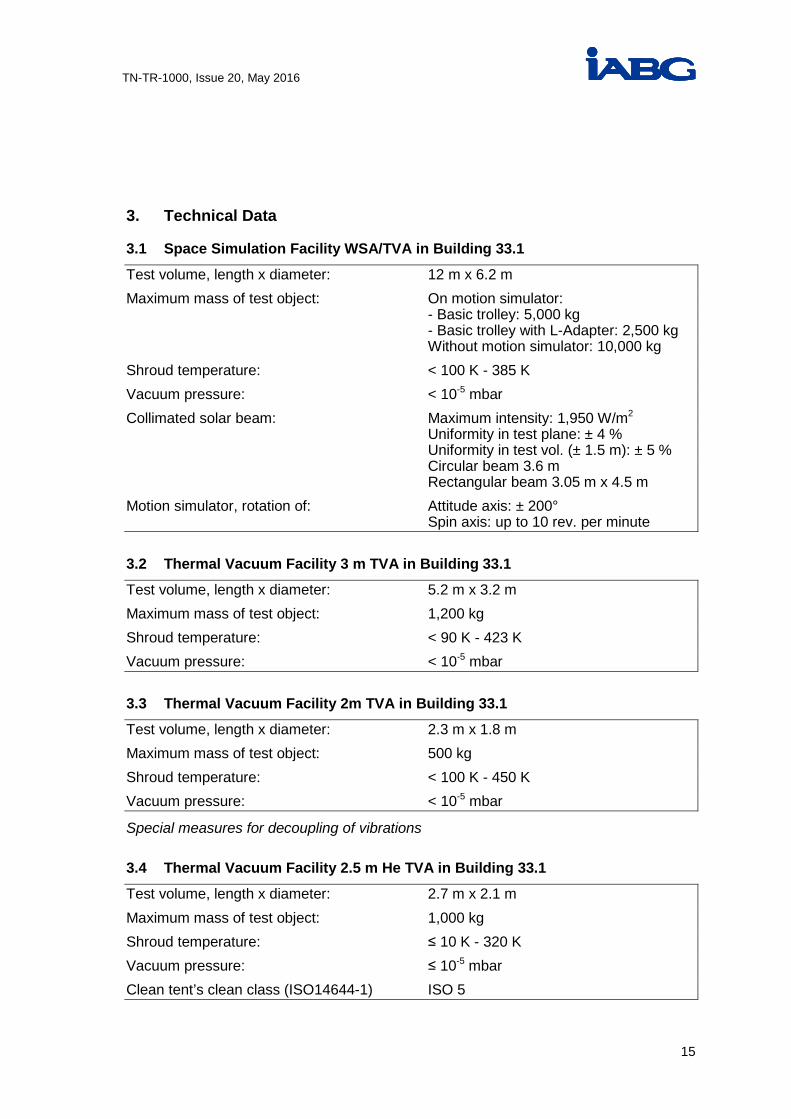
3. Technical Data
3.1 Space Simulation Facility WSA/TVA in Building 33.1
Test volume, length x diameter: 12 m x 6.2 m Maximum mass of test object: On motion simulator: - Basic trolley: 5,000 kg - Basic trolley with L-Adapter: 2,500 kg Without motion simulator: 10,000 kg Shroud temperature: < 100 K - 385 K Vacuum pressure: < 10-5 mbar Collimated solar beam: Maximum intensity: 1,950 W/m2 Uniformity in test plane: ± 4 % Uniformity in test vol. (± 1.5 m): ± 5 % Circular beam 3.6 m Rectangular beam 3.05 m x 4.5 m Motion simulator, rotation of: Attitude axis: ± 200° Spin axis: up to 10 rev. per minute
3.2 Thermal Vacuum Facility 3 m TVA in Building 33.1
Test volume, length x diameter: 5.2 m x 3.2 m Maximum mass of test object: 1,200 kg Shroud temperature: < 90 K - 423 K Vacuum pressure: < 10-5 mbar
3.3 Thermal Vacuum Facility 2m TVA in Building 33.1
Test volume, length x diameter: 2.3 m x 1.8 m Maximum mass of test object: 500 kg Shroud temperature: < 100 K - 450 K Vacuum pressure: < 10-5 mbar
Special measures for decoupling of vibrations 3.4 Thermal Vacuum Facility 2.5 m He TVA in Building 33.1
Test volume, length x diameter: 2.7 m x 2.1 m Maximum mass of test object: 1,000 kg Shroud temperature: ≤ 10 K - 320 K Vacuum pressure: ≤ 10-5 mbar Clean tent’s clean class (ISO14644-1) ISO 5

16
TN-TR-1000, Issue 20, May 2016
3.5 Ambient Pressure Thermal Cycling Chamber in Building 33.1
Test volume, length x diameter: 3.5 m x 3.5 m x 5.5 m Maximum mass of test object: 1,000 kg Test temperature: -185°C to +210°C Pressure: Ambient Clean class (ISO14644-1): ISO 8
3.6 Data Handling
Sensors: Thermocouples Cu/Ko, Si-diodes, platin resistors, thermistors, voltage signals Number of channels: Up to 2,000 customer data up to 500 housekeeping data Data Processing: Monitoring and evaluation of measured data, limit detection, average calculation, online graphic, equilibrium determination, teletesting, etc.
3.7 Additional Measuring Equipment
Mass spectrometer: Range: 0 - 200 m/e Quartz Crystal Microbalance: Mass sensitivity: 1.96 x 10⁻⁹ g/cm² Hz Infrared Spectroscope: Sensitivity: 1 x 10⁻⁹ g/cm2 Particle Counter: Range: 0.3 - 10 µm Particle Fallout Meter: Range: 3 - 2,000 PFO units
3.8 Infrared-Equipments
Irradiated areas: 3,825 mm x 2,460 mm 5,090 mm x 2,460 mm Maximum Intensity: 6.7 kW/m² Uniformity: < ± 15 %
3.9 Test Hall in Building 33.1
Preparation area: 220 m² Main hall, height: 9 m Side wing, height: 6.4 m

17
TN-TR-1000, Issue 20, May 2016
Entrance, height x width: 7 m x 6 m Clean class (ISO14644-1): ISO 8 Separate clean tent: ISO class 5 Temperature: 22°C, ± 3°C Relative Humidity: 55 %, ± 10 % Uninterruptible power supply: Max. 2 x 40 kW; cable links to different
facilities and c/o rooms Hoisting equipment (main hall): Load: 5,000 kg Movement: (Up-Down) 12/1.2/0.15 m/min (North-South): 40/10 m/min (East-West): 21/5 m/min Hoisting equipment (side wing): Load: 1,600 kg Movement: (Up-Down) 8/0.8 m/min (North-South): 10/2.5 m/min (East-West): 14/3.5 m/min Maximum load of floor: 15 kN/m
3.10 Checkout Room 1
Area: 76 m² Height above false floor: 2.9 m Hoisting capacity: 500 kg Uninterruptible power supply: Max. 20 kW Air conditioning, power consumption: 25 kW Maximum load of false floor: 20 kN/m²
3.11 Checkout Room 2
Area: 40 m² Height: 3.1 m Uninterruptible power supply: Max. 20 kW Air conditioning, power consumption: 25 kW Maximum load of false floor: 20 kN/m²

18
TN-TR-1000, Issue 20, May 2016
Fig. 5: Layout of Building 33.1

19
TN-TR-1000, Issue 20, May 2016
Space Division Vibration and Shock Test Facilities 320 kN Multi-Shaker System with LISA PATHFINDER

20
TN-TR-1000, Issue 20, May 2016
1. Tasks
§ Dynamic load tests for development and qualification
§ Experimental simulation of real loads
§ Measurements of real operational loads
§ Analysis of dynamic processes and verification of model calculations
§ Specialist advice
2. Test Facilities
The vibration and shock laboratory oper-ates several vibration facilities with grad-ed capacity and force vectors from 36 kN to 320 kN. The two biggest single shak-ers and a unique multi-shaker system are housed in an air-conditioned test hall which fulfils the clean room conditions of class 8. The pyroshock simulation equipment is mobile and can be used in standard la-boratory conditions as well as in ISO 8 clean conditions or even at customer premises. A data acquisition system with 250 chan-nels is available for measuring and eval-uating the test object responses (extend-able up to 1000 channels). The principal measurement values are acceleration, strain and force.
The digital measurement data can be transferred to customer work stations which are equipped with the DynaWorks software for extensive post processing and prediction. The smaller shakers are operated in an-other building under regular laboratory conditions. The vibration facilities are equipped with standard test fixtures and slip tables in order to expose the test ob-jects to uniaxial loads in the three ortho-gonal axes. A dedicated force measure-ment device is available for system level tests on the 320 kN shaker system. Three facilities with a force rating of up to 50 kN are equipped with thermal cham-bers in the range of -70° C to 190° C. The operating mode is both vertical and hori-zontal.

21
TN-TR-1000, Issue 20, May 2016
3. Technical Data
3.1 Multi-Shaker System (VVS)
Force rating: 320 kN sine, random Max. acceleration: Bare standard table: 15 g
With 3,000 kg payload: 6 g Min. controllable level: 0.05 g Max. displacement: ± 12 mm Frequency range: 4 - 200 Hz high level 4 - 2,000 Hz low level Max. payload mass (table excl.): 3,000 kg (with standard load suspension) 15,000 kg (with external suspension) Usable surface area: 3 m x 3 m, with 80 x 80 mm² hole pattern, M10
3.1.1 Standard Fixtures Head expander Slip table
Mass (incl. moving elements)
Max. Overturning Moment Table surface level with respect to test floor
1,900 kg 200 kNm +1.0 m
1,800 kg 1,100 kNm -0.1 m
3.1.2 Force Measurement Device
Number of lad cells: 16 Measurement RangeMax. force lateral: 480 kN Max. force vertical: 2,400 kN Dedicated signal conditioners: Online summation unit for overall force and moment determination

22
TN-TR-1000, Issue 20, May 2016
3.2 Vibration System (4022 LX)
Force rating: 200 kN sine 150 kN random Max. acceleration: Bare standard table: 40 g With 500 kg payload: 20 g Min. controllable level: 0.1 g Max. displacement: ± 15 mm (± 20 mm shock) Frequency range: 4 - 2,000 Hz Max. payload mass: 900 kg (table excl.) Usable surface area: 1.3 m x 1.3 m, with 80 mm x 80 mm hole pattern, M10
3.2.1 Standard Fixtures
Head expander Slip table
Mass (incl. moving elements) Table surface level with respect to test floor
480 kg +1.95 m
500 kg + 1.05 m
3.3 Vibration System (V964LS)
Force rating: 80 kN sine, random Max. acceleration: 100 g Min. controllable level: 0.1 g Max. displacement: ± 15 mm (± 20 mm shock) Frequency range: 5 - 2,000 Hz Max. payload mass (table excl.): 750 kg Usable surface area: up to 1 m x 1 m with 40 mm x 40 mm, hole pattern, M8 or 80 mm x 80 mm hole pattern, M10

23
TN-TR-1000, Issue 20, May 2016
3.4 Vibration Control
Two digital control systems both equipped with - LMS Test.Lab Software on a standard PC,
excitation: sine, random, transient (classical shock & SRS) - 48/36 input channels (pilots + limiter channels),
on-line monitoring of selected channels, automatic notch and abort functions, external low-pass filtering, “easy link” (24 lines) to the data acquisition system
- Safety features: limitation of shaker input current (force) emergency button (soft shut-down)
3.5 Measurement Equipment
1,500 accelerometers (various types for specific applications), mainly ICP, with full scale ranges from mg up to 200,000 g
3.6 Data Acquisition and Processing
250 measurement channels (up to 1,000 are possible) for sine and random: up to 2.5 kHz 210 measurement channels for transients: up to 5.6 kHz 100 measurement channels for strain or force: up to 2.5 kHz Data base: Universal-Files LMS-TDF-Files DYNAWorks Files
3.7 Pyroshock Simulation
Test frequency range: 100 - 20,000 Hz Max. SRS level: 10,000 g Signal sampling rate: 200 kHz

24
TN-TR-1000, Issue 20, May 2016
3.8 Test Hall (Buildings 34.0 and 34.1)
Area (see Fig. 5): 581 m² (230 m² and 351 m²) Height of hall: 9.6 m and 14.9 m Entrance, width x height: 3.4 m x 3.9 m and 6.3 m x 11.0 m Max. load on test floor: 7.5 kN/m² and 10 kN/m² Clean class (ISO14644-1): ISO 8 Temperature: 22°C, ± 3°C Relative humidity: 55 %, ± 10 % 200 kN and 80 kN systems: 1. Hoisting Equipment: Load: 3,200 kg Min. lifting speed: 30 cm/min Lifting height above test floor: 8.3 m 2. Hoisting Equipment: Load: 10,000 kg Min. lifting speed: 40 cm/min or Load: 2 x 5,000 kg Min. lifting speed: 10 cm/min Lifting height above test floor: 8 m 320 kN Multi-Shaker system: 3. Hoisting Equipment: Load: 10,000 kg Lifting speed: 0 - 2 m/min Lifting height above test floor: 12.5 m Fork Lift: Load: 1,250 kg Lifting height: 2.9 m
Transport Devices: Load: 2,000 kg Power Supply: 3 x 400/230 V: 16, 32, 64 A 50 Hz 3 x 200/115 V ± 20 %: 14.5 A 60 Hz 3 x 200/115 V ± 20 %: 8.7 A 400 Hz

25
TN-TR-1000, Issue 20, May 2016
Fig. 6: Layout of Building 34.0/34.1 Vibration Facilities

26
TN-TR-1000, Issue 20, May 2016
Space Division Modal Test Facility
Modal Survey Test on VEGA Launcher

27
TN-TR-1000, Issue 20, May 2016
1. Tasks
§ Experimental and analytical vibration investigations, in particular supporting dynamic, acoustic, fatigue, and func-tional aspects during the develop-ment phase of equipment and pro-ducts
§ Determination of the modal character-istics of mechanical structures by test
§ Test assisted development and verifi-cation of mathematical models
§ Performance of micro-gravity qualifi-cation tests
§ Measurement and analysis of opera-tional vibration responses (e.g. modal analysis of vibration test data)
§ Identification of critical excitations and vibration-susceptible structural areas
§ Design and testing of remedial measures for vibration problems
§ Optimisation of the dynamic behav-iour of mechanical systems
§ Consultancy in the field of structure dynamics, in particular with respect to acoustic phenomena
2. Test Facilities
Modal vibration exciters rated from 10 N to 7 kN for the excitation of test objects and a versatile test facility for the meas-urement and analysis of artificially or nat-urally excited dynamic responses are available for experimental vibration inves-tigations. The versatile modal test facility (VMT) incorporates test control, acquisition and analysis for the state-of-the-art phase resonance and phase separation meth-ods. The facility can be scaled in units of 126 measurement channels to meet any test requirement up to 1,000 channels. Particular features of the modal test facili-ty are its exceptional frequency range of sine operation between 0.2 Hz up to 35 kHz and its automatic mode for force appropriation testing.
In addition, several DC powered mobile systems with up to 48 channels are available for in-vehicle operational vibra-tion. All systems are mobile and can be used at short notice at any test site. This equipment is complemented by a laser scanning vibrometer for contactless measurements of vibrations. The modal test performance is computer controlled. The evaluation of the meas-ured signals and the presentation of the test results are conducted with the help of sophisticated up-to-date software tools. An air-conditioned test hall with clean conditions of ISO class 8 is available for the conduct of the investigations. The hall contains a seismic foundation for fixing the test objects.

28
3. Technical Data
3.1 Excitation
Sine wave generators: Up to 30 kHz Random noise generators: Up to 25 kHz Simultaneous control: Sine and random: 12 channels Vibration exciters: 10 N up to 7 kN Instrumented hammers: 140 g up to 5 kg
3.2 Measurement
400 standard accelerometers: Up to 5,000 m/s² and 10 kHz with sensitivity values ranging from 10 mV/g to 10 V/g Additional transducers for displacement, force, pressure, strain and special environ-mental conditions, also further accelerometers can be made available.
3.3 Data Acquisition
Sine: Up to 1,000 channels in parallel: 0.2 Hz - 10 kHz Up to 500 channels in parallel 0.2 Hz - 35 kHz Random, general time signals: Up to 1000 channels in parallel: 0 - 20 kHz Up to 500 channels in parallel 0 - 40 kHz Data base (for exchanging data): Universal Files
3.4 Computers
Networked and standalone Windows work stations with Internet gateway.
Disk storage units, CD and DVD for data exchange
High quality colour printers / plotters

29
3.5 Test Hall
Area (see Fig. 8): 328 m²
Height of hall: 15 m
Entrance, width x height: 5.9 x 10 m and 6.3 m x 11.0 m
Maximum floor load: 20 kN/m²
Maximum block load on 2.5 m x 2.5 m: 250 kN
Clean class (ISO14644-1): ISO 8
Temperature: 22°C, ± 3°C
Relative humidity: 55 %, ± 10 %
Test foundation (Fig. 8): Area: 10 m x 13 m Mass: 250,000 kg
Anchor rails (HTA 72/48 mm): Distance: 1 m Loading: 108 kN/m
Test hall crane: Max. Load: 10,000 kg Lifting speed: 0 - 2 m/min Lifting height: 12 m
Power Supply: 3 x 400/230 V, 50 Hz 16, 32, 63 A 3.6 Standard Test Fixtures
Base plates 2.2 m x 2.2 m x 0.1 m and 3.1 m x 3.1 m x 0.1 m with ARIANE 5 ACU hole pattern, rigidly fixed to the test foundation.

30
Fig. 7: Versatile Modal Test System (VMT)

31
Fig. 8: Layout of Building 33.5, Multi Purpose Hall, e.g. used for structure tests

32
Space Division Acoustic Noise Test Facility
SWARM S/C Stack in the Acoustic Test Facility

33
1. Task
Acoustic noise tests are performed to qualify the test object for the acoustic environments encountered during the mission of spacecraft. During launch, the most severe acoustic phases are the lift-off and the transonic regime. This severe
acoustic environment is simulated in a reverberation chamber. In addition, fluc-tuating pressure fields, such as during atmospheric descent, are simulated in a special Progressive Wave Tube.
2. Test Facilities
Acoustic noise tests are performed in the acoustic facility with a reverberation chamber of V = 1,378 m³ (156 dB OASPL), or in a progressive wave tube for high intensity (170 dB OASPL) tests. These installations are directly accessible from the existing space test facilities (see Fig. ) such that a test object must not leave the clean area when performing a series of qualification tests. In the rever-beration chamber, the test object is ex-posed to a diffuse sound field with sound waves impinging from all directions. The noise generation system is based on three air compressors providing a maxi-mum air flow of 6 kg/s for three noise generators and horns (see Fig. 10). The test control and measurement system consists of 24 microphone channels and of 256 regular response channels (see Fig. 10).
Test control is performed using an auto-matic control system. In cases where the test object is to be excited from one side only, the use of the Progressive Wave Tube is favourable. In this case the test specimen is flush-mounted into one of the walls and excited by progressive waves inside the tube. A separate control and measurement room, a preparation hall of a 115 m² area and a measurement room for customers form additional elements of the infrastruc-ture.

34
3. Technical Data
3.1 Reverberation Chamber
Chamber, depth x width x height (cube): 8.9 m x 10.4 m x 15.2 m
Main door, width x height: 6.5 m x 15.2 m Crane capacity: 16,000 kg Clean class (ISO14644-1): ISO 8 Temperature: Relative humidity: Max. acoustic power: 3 x 30 kW ac OASPL (broadband): 156 dB Acoustic spectrum: 25 Hz £ f £ 10 kHz Duration of noise exposure: Unlimited Data acquisition and reduction: 24 microphone channels
256 response data channels up to 64 strain channels
1/1 oct.-, 1/3 oct.-, 1/12 oct.- PSD-Analysis RMS values, correlation and other sta-tistical functions
3.2 Progressive Wave Tube
Test section: 0.8 m x 1.2 m
Max. acoustic power: 3 x 30 kW ac OASPL (broadband): 170 dB Acoustic spectrum: 25 Hz £ f £ 10 kHz Duration of noise exposure: Unlimited Data acquisition and reduction: 12 microphone channels
48 response data channels up to 64 strain channels
1/1 oct.-, 1/3 oct.-, 1/12 oct.- PSD-Analysis RMS values, correlation and other sta-tistical functions

35
3.3 Preparation Hall
Dimensions, area, height: 110 m², 15.2 m
Main door, width x height: 6.2 m x 9.9 m
Hoisting equipment: 1 crane bridge 16 t (running into the reverberation chamber) lifting height 11.6 m (13 m) overhead crane qualified to 156 dB OASPL
Temperature: 22°C, ± 3°C Relative humidity: 55 %, ± 10° C Clean class (ISO14644-1): ISO 8
Fig. 9: Layout of the Acoustic Test Facility
TP-C
Bldg. 34.2
Control room Measurementand evalu-ation room
Reverberationchamber
Control/measurement
room
VIBRATION TESTSProgressivewave tube
Shakers
Customersroom
TESTPREPA-RATION
Horn chamber
Medium voltageunit
Low voltageunit
Customeroffice
Lift
an lock D
angingom D
Trans-former 1
Trans-former 2
Trans-former 3
Control/measurement
roomClean lock
Changing room
Exit
Exit
VIBRATIONTESTS
ACOUSTICTESTS
Exit
200 kN (4022LX)
80 kN
50 Hz
30 Hz
53 kN (A540)
36 kN(V875)
Exit

36
Fig. 2: Block Diagram of the Noise Generation System

37
Space Division EMC Test Facility
EMC Test on CryoSat S/C
38
1. Tasks
EMC emission and susceptibility testing in accordance with § Space Standards such as
ECSS-E-ST-20-07C and others
§ Military Standards such as MIL-STD-461/462 B-F and others
§ Aviation Standards, such as RTCA/DO-160, AIRBUS, BOEING, EUROCOPTER
§ Emission and susceptibility test
§ Measurement of shielding attenuation
§ HIRF and indirect lightning effects
§ Simulation of mobile communication on GSM Frequencies
§ Power characteristics and simulation
§ Consulting and Hardening § Special customer requirements
2. Test Facilities
The EMC test facilities are accredited by DAkkS according to ISO/IEC 17025. and certified according to EN 9100. The test facilities consist of one large shielded anechoic chamber with a shield-ed anteroom and two medium anechoic chambers with anteroom. Emissions are measured with computer controlled EMI-Receiver Systems and FFT-Analysers. By means of this equipment EMC tests can be conducted in the range from 10 Hz to 40 GHz in compliance with the ap-plicable standards.
Generators, high-power amplifiers and special antennas are available to gener-ate electro-magnetic fields of more than 4,000 V/m (depending on the frequency range). Transients, such as spikes, indi-rect lightning (LEMP), electro-static dis-charge (ESD), multiple burst and stroke can be simulated. Electrical tests for simulation of power supply systems can be performed at vari-able frequencies (overvoltage, interrup-tions, surges).

39
3. Technical Data
3.1 Chamber Characteristics
Large Anechoic Chamber Medium Anechoic Chambers Length x width x height: 10.5 m x 7.2 m x 8.2 m 5.4 m x 4.3 m x 2.7 m (EMV2) 4.6 m x 4.6 m x 2.7 m (EMV3) Anteroom: 6.5 m x 9.0 m x 3.5 m 2.7 m x 6.3 m x 2.8 m (EMV2) 2.7 m x 5.5 m x 3.0 m (EMV3) Max. floor load: 29 kN/m² 30.0 kN/m² Single point load: 10.0 kN/m² unit 5.0 kN/m² unit Dimensions of door, 6.0 m x 4.0 m 0.89 m x 1.9 m (EMV2) width x height: 1.0 m x 2.1 m (EMV3) Clean class (ISO14644-1): ISO 8 Visibly clean Temperature: 22°C, ± 3°C 22° C, ± 3° C Relative humidity: 55 %, ± 10 % 55 %, ± 10 % Compressed air and water supply: Available Available Exhaust tail pipe: Available - Hoisting equipment: Load: 5,000 kg - Min. lifting speed: 30 cm/min Fire detection system: Available Available Fire fighting system: Handheld Extinguisher Handheld Extinguisher Shielding attenuation: H-field: H-field: 10 kHz > 60 dB 10 kHz > 60 dB above 1 MHz > 100 dB 100 kHz > 70 dB above 1 MHz > 80 dB Absorber reflectivity: 70 to 300 MHz > 19 dB Ferrite: 300 MHz - 40 GHz > 30 dB 10 MHz - 1 GHz > 17 dB Pyramides: 100 MHz - 18 GHz > 20 dB Power handling: 1 kw/m² (600 V/m) 1 kW / m² (600 V/m) continuously continuously

40
3.2 Equipment for Emission Tests 3.2.1 Frequency Domain
EMI Receivers 5 Hz - 40 GHz
Spectrum Analyzer FSU 20 Hz – 50 GHz
Current Probes 10 Hz - 150 MHz
Active Rod Antennas ISE 10 kHz - 50 MHz
Broadband Dipoles Fairchild 25 MHz - 1 GHz
Circular Broadband Helix Fairchild 200 MHz - 1 GHz
Std. Gain Horns Heine 0.8 - 40 GHz
Double Ridged Horns EMCO/ Schwarzbeck
0.2 - 40 GHz
Passive Magnetic Loop RE101 10 Hz - 150 kHz
Active Magnetic Loop HFH-Z2 9 kHz - 30 MHz
3.2.2 Time Domain
Digital Storage Oscilloscope TEK 4 GS/s
Digital Storage Oscilloscope Agilent 300 MHz
Data Recorders
Differential Voltage Probes DC - 200 MHz
High Voltage Probes DC - 1 GHz
High Current Probes DC - 50 MHz
High Speed Current Probes ESD Currents

41
3.3 Equipment for Susceptibility Tests 3.3.1 Frequency Domain
RF generators and synthesizers 1 mHz - 40 GHz
AF Amplifier 2 kW DC - 150 kHz
CW Amplifiers 2 kW 750 W 500 W 200 W 5 W 320 W 1 W
10 kHz - 220 MHz 200 - 500 MHz 500 MHz - 1 GHz 1 GHz - 8 GHz 8 GHz - 18 GHz 8 GHz - 18 GHz 18 GHz - 40 GHz
Pulse Sources 4 kW 3 kW 2 kW 2 kW 2 kW
200 MHz - 500 MHz 500 MHz - 1 GHz 1 GHz - 2 GHz 2 GHz - 8 GHz 8 GHz - 18 GHz
TEM Cell 10 kHz - 300 MHz
Parallel Plate Antenna 10 kHz - 200 MHz
Stripline 10 kHz - 200 MHz
E-Field Generator 10 kHz - 30 MHz
Logper Antenna 100 MHz - 200 MHz
BiLogper Antenna 30 MHz - 1 GHz
Std. Gain Horns 800 MHz - 40 GHz
Double Ridged Horns 200 MHz - 40 GHz
B-Field Indicator 10 Hz - 30 kHz
E- Field Indicator 10 kHz - 50 GHz
Current Injection Probes 10 kHz - 400 MHz
Current Monitor Probes DC - 1 GHz
LISNs DO-160 ; MIL ; EFA
Coupling Device AF-Transformer 2:1
Induced Signal (Voltage) Transformer 12 kV
Induced Signal (Current) Transformer 120 A
Susceptibility Software RSUS

42
3.3.2 Time Domain Arbitrary Generator DC - 20 MHz
Bipolar Operational Amplifier 2 kW DC - 150 kHz
CS06 MIL-STD-461C/462 ± 1kV Spike 150 ns, 10 µs
CS115 MIL-STD-461/462D,E Spike 30 ns
CS116 MIL-STD-461/462D,E 10 A Damped Sinus 10 kHz - 100 MHz
Half Sine 5 µs
Fast Pulse EFA 0.1/2 µs
Slow Wave Airbus (Single Stroke)
40/95 µs
Fast Wave Airbus (Single Stroke) 1/10 µs
Long Wave (Single Stroke) 2/50 µs
Communication Pulse
Lightning - Single Stroke - Multiple Stroke - Multiple Pulse - Multiple Burst
Level 5 Level 3 Level 3 Level 5 Level5
Waveforms: wave 1: 6.4/70 µs (I) wave 2: 0.1/6.4 µs wave 3: 1 MHz/10 MHz wave 4: 6.4/70 µs (U) wave 5A: 40/120 µs wave 5B: 50/500 µs
Voltage Spike AMD24 (LD104, SVF104 etc.)
10 µs, 50 µs, 100 µs, 400 µs
ESD Networks: 150pF/330W (16kV, Air) 150pF/150W (30kV, Air) 100pF/1.5 kW (16kV, Air)

43
3.4 Power Supply for Customer Equipment and Test Articles Mechanical Converter Lechmotoren 3 x 115/200VAC 40
kVA, 400 Hz,åand r
Switched DC/AC Supply REFU 3 x 0-200 V DC/AC 90 kVA, DC - 2 kHZ without N, only r
Programmable DC/AC Supply ELGAR 3 x 0-400 V DC/AC 15 kVA, DC - 1 kHz åand r
Programmable DC/AC Supply Cal. Instr. 3 x 0-400 V DC/AC 45 kVA, DC - 1 kHz åand r
DC Power Supplies HP 0 - 60 VDC 30 A
HP
Sorensen
0 - 150 VDC 15 A
0 - 40 VDC 250 A
Fig. 10: Large EMC Anechoic Chamber (EMV1)

44
Fig. 11: Medium EMC Anechoic Chamber (EMV2)
Fig. 12: Medium EMC Anechoic Chamber (EMV3)

45
Bldg. 33.7
EMC 1 anteroom
TP-A
Customers room Kitchen
LaW
Exit
EMC LAB 1
CHECOU
ROOM
Exit
EMCLAB 2
EMCLAB 4
EMCLAB 3
EMC 2 anteroomEMC 3 anteroom
Fig. 13: Layout of the EMC Test Facilities

46
Space Division Magnetic Test Facility
SWARM S/C during a magnetic test
47
1. Tasks
§ Measuring the DC and AC magnetic cleanliness of test objects
§ Magnetising and demagnetising of test objects to determine permanent, remanent and induced magnetic fields
§ Measuring the dipole/multipole field distribution surrounding the test ob-jects
§ Modelling and predicting of far fields of a test object
§ Modelling DC magnetic fields of a spacecraft based on several unit measurements
§ Technical consulting for magnetic cleanliness
§ Measuring magnetic moments
§ Measuring eddy current fields
§ Attitude control testing of magnetically stabilised spacecraft systems
§ Calibrating magnetometers
§ Magnetic Effect Test (RTCA/DO160)
§ EN 61000-4-8/9/10 up to 1,000 A/m
§ ISO 10373 and ISO 7816 800 kA/m
§ Immunity at 16 2/3, 50 and 400 Hz
2. Test Facility
The magnetic test facility consists of a non-magnetic wooden building of 8,000 m3 in size. The facility was built in a loca-tion free of earth field gradient, far enough from major sources of disturb-ance such as industrial areas, railways and power lines. The core of the facility consists of an aluminium structure sup-porting a 3-axial coil system with 4 coils per axis, capable of producing static and dynamic field vectors in any direction or a
zero field if required (see Fig. 15) Fig. Test articles are located in the centre of the coil system where high precision magnetic measurements can be per-formed in an area of 4 m x 4 m x 4 m. Test objects for space application can be tested under clean conditions of ISO class 8 and controlled environmental pa-rameters.

48
3. Technical Data
3.1 Large Coil System
Type: Square coil system, 4 coils per axis, 3 orthogonal axes Dimensions: 15 m x 15 m x 15 m, free access area 4 m x 4 m Zero field: Compensation of the earth's field with a resolution of 0.1 nT Uniformity of created magnetic field: 5.0 nT in 4 m diameter, *1 Stability of facility: 0.5 nT/hour D.C. field: Range: 0 - 75,000 nT in each axis with a resolution of 0.1 nT Accuracy: 1 nT A.C. field: Frequency range: 0.01 - 3 Hz Amplitude range: 0 - 75,000 nT resp. 100,000 nTHz *2 Frequency range: 3 - 3,600 Hz Amplitude range: 0 - 10,000 nTHz *1 Additional external generated magnetic field gradients have to be taken into account sepa-rately. *2 nTHz is a unit related to the induction law: U = - dB/dt: i.e. voltage is change of the flux density per second. Example: 1,000 nTHz is equal to 1 nT at 1,000 Hz or 1,000 nT at 1 Hz.

49
3.2 Magnetisation and Demagnetisation
Square Helmholtz coil system Dimension: 3.7 m x 3.7 m, horizontal field Uniformity: 30 % in 3.0 m diameter, horizontal field Magnetisation: With D.C. fields of 1 - 4,000 A/m. Demagnetisation: With A.C. fields Start. amplit. of 160 - 4,000 A/m Duration of demagnetisation: Depending on requirements, typically 10 min Residual field: < 0.25 A/m Further coil systems and power supplies exist for different demagnetisation volumes and levels. 3.3 Magnetometer *
Fluxgate magnetometer with triple or single probes (second harmonics measurement) DC application: Range: 0 - 1 mT Accuracy: 0.1 % resp. 100 pT Resolution: 0.2 pT Protonspin magnetometer (Nuclear precision) DC application: Omnidirectional Range: 20,000 - 120,000 nT Accuracy: 0.3 nT Resolution: 10 pT Search coil magnetometer (ferrite loop antenna) AC application: Frequency range: 0.034 Hz - 30 KHz Amplitude range: 200 µT Sensitivity: 24 mV/µT * for details please refer to STL data sheet

50
3.4 Test Hall
Dimensions, length x width x height: 20 m x 20 m x 20 m Entrance: 5 m x 5 m Clean class (ISO14644-1): ISO 8 Temperature: 22°C ±3°C Relative humidity: 55% ±10% Crane in entrance hall on rail: Approximately 16 m long Load: 1,500 kg Lifting height: 5 m Hoist above centre of facility: Load: 1,000 kg Lifting height: 10 m Trolley: Load: 1,500 kg Movable on rails through facility and entrance hall Turntable: Load: 1,500 kg, can be mounted on trolley

51
Fig. 14: Schematic Diagram of Magnetic Test Facility MFSA

52
Space Division Mass Property Measurements
AMOS 2 on the Mass Property Measurement Device

53
1. Tasks
For satellites, space probes, launcher parts, their subsystems and payloads, or for any kind of general engineering sys-tems a complete set of facilities is avail-able for the accurate determination of the mass properties.
They comprise: § Mass (weight)
§ Centre of gravity (CoG)
§ Moment of inertia (MoI)
§ Product of inertia (PoI) Furthermore, static and dynamic balanc-ing or the determination of residual un-balances can be performed.
2. Test Facilities
For any kind of mass property measure-ment at least two measuring devices with different load capacities and measure-ment ranges are available. Therefore, the most suitable test equipment can be used for a specimen in order to meet various weight, dimension and accuracy require-ments. Six different high precision weight scales provide accuracies between 0.003 % and 0.03 % of the specimen’s mass. This pre-cise measurement is fundamental for further exact mass property measure-ments. The centre of gravity (CoG) of a speci-men can be determined with two different CoG scales. One can be used for small sized and light parts, the other one is ca-pable of carrying specimen up to system level. The WM50/6 scale enables determination of the CoG and the MoI (moment of iner-tia) by using the same attachment plane. This allows the performance of two differ-ent types of tests without changing the test set-up. Beside this combined machine another oscillation table with different accuracy
and loading capacity is available for MoI determination. For CoG measurements with respect to the specimen’s vertical axis and for MoI measurements with respect to axes in the horizontal plane an L-shaped adapter with a rotatable interface plate is availa-ble. It enables the fixation of the horizon-tally orientated specimen and MoI meas-urements around the lateral axes. In this way the specimen’s principal axes. re-spectively the product of inertia (PoI) in the horizontal plane can be determined. The test specimen can be attached to the ”L-Adapter“ at the specimen‘s transport position. The L-adapter turning equip-ment (LATE) is capable to rotate the L-Adapter together with the test specimen into vertical position and vice versa. With the L-Adapter lifting device (LLD) the L-Adapter can be lifted onto the MPM ma-chines together with the specimen. The MPM facilities also provide one bal-ancing machine. A typical application of a balancing test is the elimination of static and/or dynamic unbalances, the meas-urement of residual unbalances or the determination of the PoI with respect to the (vertical) spin axis.

54
3. Technical Data
3.1 Weight Scales There are six weight scales available with the following characteristics: Weight Range: Accuracy: up to 8 kg ± 0.5 g up to 60 kg ± 2.0 g up to 600 kg ± 20.0 g up to 1,000 kg ± 100.0 g (up to 600 kg ± 50 g) up to 3,000 kg ± 200.0 g (up to 1,000 kg ± 100 g) up to 6,000 kg ± 500.0 g 3.2 Centre of Gravity Scales
Weight Range: Best achievable accuracy: 0.7 - 20 kg ± 0.3 mm 20 - 6,000 kg ± 0.5 mm (up to 50 kg ± 1 mm) 3.3 Oscillating Tables for MoI
MoI Range: Best accuracy: Weight: 0.05 - 0.1 kgm² ± 2 % small equipment 0.1 - 1.0 kgm² ± 1 % small equipment 1.0 - 2,000 kgm² ± 0.5 % 2,000 kg 150 - 17,000 kgm² ± 0.5 % 6,000 kg 3.4 Balancing Machines
Weight Range: Rotation Speed: Accuracies: Up to 2,800 kg 20 - 160 RPM 0.14 – 7.0x10⁻⁴ kgm 0.20 – 7.0x10⁻⁴ kgm2

55
3.5 Test Hall
Hall area: 200 m² Height: 15.3 m Clean class (ISO-14644-1): ISO 8 Temperature: 22°C ± 3°C Relative Humidity: 55 ± 10 % Max. floor load: 20 kN/m² Crane, hoisting capacity: 10,000 kg Crane max. height of hook: 11.6 m
Fig. 15: Layout of the MPM Test Facility

56
Space Division Calibration Facilities
Sinusoidal Calibration of an Accelerometer Sinusoidal Calibration of an Accelerometer

57
1. Tasks
IABG provides facilities for calibration of: § Multimeters
§ Resistors
§ Current probes
§ Counters
§ Temperature probes
§ Thermocouple reference junctions
§ Dynamic motion measuring transduc-ers, electronics and systems
§ Accelerometers
§ Charge amplifiers There are facilities for sinusoidal and shock calibration of accelerometers available. In both cases a comparison method is used, i.e. the calibration is re-lated to a reference standard. These pri-mary standards are calibrated optically by interferometric methods at the National Metrology Institute PTB (Physikalisch Technische Bundesanstalt).
2. Calibration Procedures
The calibration procedure to be applied is depending on the quantity metered or on requirements specified by the customer. It can be performed according to either AQAP6, MIL-STD-45662 or DKD proce-dures. The Space Division provides a DKD cali-bration laboratory for vibration instru-ments (DKD-K-01401) at IABG. Under the roof of the DKD (Deutscher Kalibrier-Dienst) calibration laboratories of industrial companies, science insti-tutes, technical authorities, safety engi-neering and test institutes are joined to-gether. They are accredited and moni-tored by the accreditation body of DAkkS.
The DKD calibration certificates are proof of a return to a national standard. Aside from this, other technical and administra-tive regulations for the laboratory apply such as EN 9100 and ISO/IEC 17025. Calibrations performed by DKD laborato-ries guarantee the reliability of measuring equipment. The use of DKD calibrated measuring equipment increases the con-fidence of the customers and the compet-itiveness on the national and international market.
58
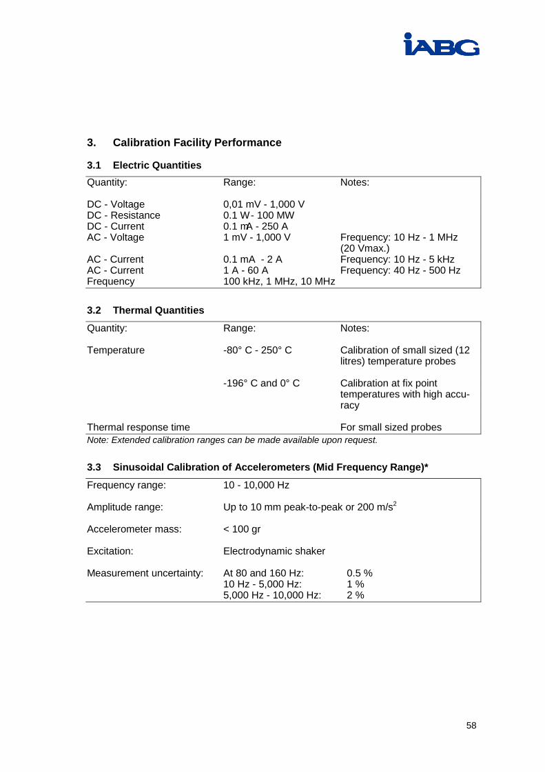
3. Calibration Facility Performance
3.1 Electric Quantities Quantity: Range: Notes: DC - Voltage 0,01 mV - 1,000 V DC - Resistance 0.1 W - 100 MW DC - Current 0.1 mA - 250 A AC - Voltage 1 mV - 1,000 V Frequency: 10 Hz - 1 MHz (20 Vmax.) AC - Current 0.1 mA - 2 A Frequency: 10 Hz - 5 kHz AC - Current 1 A - 60 A Frequency: 40 Hz - 500 Hz Frequency 100 kHz, 1 MHz, 10 MHz 3.2 Thermal Quantities
Quantity: Range: Notes: Temperature -80° C - 250° C Calibration of small sized (12 litres) temperature probes -196° C and 0° C Calibration at fix point temperatures with high accu- racy Thermal response time For small sized probes Note: Extended calibration ranges can be made available upon request. 3.3 Sinusoidal Calibration of Accelerometers (Mid Frequency Range)*
Frequency range: 10 - 10,000 Hz Amplitude range: Up to 10 mm peak-to-peak or 200 m/s2
Accelerometer mass: < 100 gr Excitation: Electrodynamic shaker Measurement uncertainty: At 80 and 160 Hz: 0.5 % 10 Hz - 5,000 Hz: 1 % 5,000 Hz - 10,000 Hz: 2 %

59
Calibration method: Comparison of acceleration levels using a traced cali-brated reference accelerometer
Documentation: DKD calibration certificate including: Sensitivity at customer defined frequency (normally 80 Hz) and excitation (normally 10 g) plot of normalised sensitivity: Expressed in % units in the frequency range of 10 Hz - 10 kHz expressed in dB units to indicate the main resonance frequency and any local resonances in the frequency range from 4 Hz - 50 kHz (not accredited).
* This calibration is accredited by PTB and therefore directly traceable to national standards. 3.4 Sinusoidal Calibration of Accelerometers (Low Frequency Range) *
Frequency range: 0.5 - 100 Hz Amplitude range: Up to 150 mm peak-to-peak or 10m/s2
Accelerometer mass: < 100 gr Excitation: Electrodynamic shaker Measurement uncertainty : 0.5 - 1 Hz 0.8 % (sensitivity) 0.5 degree (phase) 1 - 20 Hz: 0.5 % (sensitivity) 0.5 degree (phase) > 20 - 100 Hz : 0.8 % (sensitivity) 2 degree (phase) Calibration method: Comparison of acceleration levels using a traceable calibrated reference accelerometer Documentation: DKD calibration certificate including: Sensitivity at customer defined frequency (normally 40 Hz) and excitation (normally 0.5 g) plot of normalised sensitivity expressed in % or dB units or phase angle in degrees * This calibration is accredited by PTB and therefore directly traceable to national standards.

60
3.5 Shock Calibration of Accelerometers (Low Amplitude Range)*
Acceleration range: 200 - 100,000 m/s2
Accelerometer mass: < 50 gr Pulse shape: Half-sine pulse Duration of pulse: Depends on level: Approx. 3 ms at 200 m/s2
Approx. 100 ms at 100,000 m/ s2
Measurement uncertainty : 200 - 1,500 m/s2: 1 %* > 1,500 - 5,000 m/s2: 1.5 %* > 5,000 - 100,000 m/s2: 5 %* Excitation: Pneumatically operated projectile (POP)
to impact a cylindrical anvil to which the reference and the test accelerometer are attached
Calibration method: Comparison of peak acceleration using
a traceable calibrated reference accel-erometer
Documentation: DKD calibration certificate including: Sensitivity i.e. mean value of 10 mea- surements at one acceleration level selectable by the customer * This calibration is accredited by PTB and therefore directly traceable to national standards. 3.6 Calibration of Charge and Voltage Amplifiers*
Frequency range: 0.5 Hz - 50 kHz Amplitude Range: 0.1 pC - 10,000 pC 1 mV - 30 V Measurement uncertainty : 0.5 Hz - 10 kHz 0.3 % > 10 kHz - 30 kHz 0.6 % > 30 kHz - 50 kHz 1 % Documentation: DKD calibration certificate including: Transfer factors and plots of normalised frequency response expressed in % or dB units * This calibration is accredited by PTB and therefore directly traceable to national standards.