Embed Size (px)
Citation preview

Survey Manual
Chapter 3
GPS/GNSS Surveys
Colorado Department of Transportation
January, 2008

CDOT Survey Manual 2 January, 2008 CDOT Survey Manual January, 2003
CDOT Survey Manual January, 2003
TABLE OF CONTENTS
Chapter 3 – Global Positioning System / Global Navigation Satellite System
3.1 GPS Survey Specifications ............................................................................................................. 4 3.1.1 General ....................................................................................................................................... 4
3.1.2 GPS Methods.............................................................................................................................. 4
3.1.3 Specifications ............................................................................................................................. 4
3.1.4 Specification Types .................................................................................................................... 4
3.1.5 Colorado High Accuracy Reference Network (CHARN) .......................................................... 5
3.1.6 GPS Equipment .......................................................................................................................... 6
3.1.7 GPS Reports ............................................................................................................................... 6
3.1.8 GPS Control Monument Database ............................................................................................. 8
3.1.9 GPS Operations Manual ............................................................................................................. 9
3.2 Error Sources in GPS ................................................................................................................... 10 3.2.1 General ..................................................................................................................................... 10
3.2.2 Multipath .................................................................................................................................. 10
3.2.3 Ionosphere ................................................................................................................................ 10
3.2.4 Positional Dilution of Precision (PDOP) ................................................................................. 11
3.2.5 Equipment Error ....................................................................................................................... 11
3.2.6 Precise Ephemeris .................................................................................................................... 11
3.2.7 Human Error ............................................................................................................................. 11
3.3 GPS Equipment Checking and Calibration ............................................................................... 13 3.3.1 General ..................................................................................................................................... 13
3.3.2 Checking and Calibration ......................................................................................................... 13
3.3.3 Equipment Maintenance ........................................................................................................... 13
3.3.4 Federal Published Calibrated Baseline Check ......................................................................... 14
3.3.5 Existing CDOT Primary Control Check .................................................................................. 15
3.3.6 Zero Baseline Check ................................................................................................................ 16
3.4 GPS Survey Methods .................................................................................................................... 17 3.4.1 23 CFR 630.402 - Geodetic...................................................................................................... 17
3.4.2 CHARN Densification Surveys (CHARND) ........................................................................... 17
3.4.3 Static GPS Surveys................................................................................................................... 21
3.4.4 Fast Static GPS Surveys ........................................................................................................... 22
3.4.5 RTK GPS Surveys .................................................................................................................... 23
3.4.6 RTK Site Calibrations .............................................................................................................. 23
3.4.7 PPK GPS Surveys .................................................................................................................... 24
3.4.8 GPS for GIS Mapping Grade Surveys ..................................................................................... 25
3.5 Static and Fast Static Network Design ........................................................................................ 26 3.5.1 Required Existing Control Monumentation ............................................................................. 26
3.5.2 Network Geometry ................................................................................................................... 26
3.5.3 Redundancy of Networks ......................................................................................................... 26
3.5.4 Independent (Non-Trivial) Baselines ....................................................................................... 27
3.5.5 Network Loops ......................................................................................................................... 28
3.5.6 Twenty Percent Rule ................................................................................................................ 28
3.6 GPS Planning ................................................................................................................................ 29 3.6.1 Control Monumentation Site Selection .................................................................................... 29

CDOT Survey Manual 3 January, 2008 CDOT Survey Manual January, 2003
CDOT Survey Manual January, 2003
3.6.2 Ephemeris ................................................................................................................................. 29
3.6.3 Satellite Geometry .................................................................................................................... 30
3.6.4 Elevation Mask ......................................................................................................................... 30
3.6.5 Weather Conditions .................................................................................................................. 30
3.7 GPS Vertical Procedures .............................................................................................................. 32 3.7.1 Antenna Height Measurement .................................................................................................. 32
3.7.2 GPS Derived Orthormetric Heights (Elevations) ..................................................................... 35
3.7.3 CDOT Class A – Primary Vertical Surveys ............................................................................. 36
3.7.4 CDOT Class B – Secondary Vertical Surveys ......................................................................... 36
3.7.5 CDOT Class C – TMOSS Vertical Surveys ............................................................................ 37
3.7.6 CDOT Class D – TMOSS Vertical Surveys ............................................................................ 37
3.8 GPS Horizontal Procedures ......................................................................................................... 38 3.8.1 Minimum Horizontal Accuracy Tolerance Table .................................................................... 38
3.8.2 CDOT Class A – Primary Horizontal Surveys......................................................................... 38
3.8.3 CDOT Class B – Secondary Horizontal Surveys ..................................................................... 38
3.8.4 CDOT Class C – TMOSS Horizontal Surveys ........................................................................ 39
3.8.5 CDOT Class D – TMOSS Horizontal Surveys ........................................................................ 39
3.8.6 Process for State Plane Coordinate Reduction ......................................................................... 39
3.9 Project Control Diagram and Land Survey Control Diagram ................................................. 41 3.9.1 Project Control diagram ........................................................................................................... 41
3.9.2 Land Survey Control Diagram ................................................................................................. 41
3.9.3 TMOSS Surveys ....................................................................................................................... 41
3.10 NAD83(NSRS2007) National Readjustment ........................................................................... 42 3.10.1 General .................................................................................................................................. 42
3.11 NGS National Height Modernization Program (NHMP) ...................................................... 43 3.11.1 General .................................................................................................................................. 43
3.12 Continually Operating Reference Stations (CORS) ............................................................... 44 3.12.1 General .................................................................................................................................. 44
3.12.2 CORS Stations use for Static, Fast Static, RTK, or PPK Surveys ........................................ 44
3.13 On-line Positioning User Service (OPUS) ............................................................................... 46 3.13.1 General .................................................................................................................................. 46
3.13.2 OPUS use for Static, Fast Static, RTK, or PPK Surveys ...................................................... 46
3.14 References ................................................................................................................................... 47

CDOT Survey Manual 4 January, 2008 CDOT Survey Manual January, 2003
CDOT Survey Manual January, 2003
3.1 GPS/GNSS Survey Specifications
3.1.1 General
The purpose of this chapter is to define the specifications that shall be followed while performing
GPS/GNSS surveys for CDOT by CDOT surveyors or contract consultant surveyors. As advances in
GPS technology are made in hardware and processing software that prove a higher degree of accuracy is
more easily attained, new specifications for CDOT shall be developed and sections of this chapter shall
be revised to stay current with those advances.
For brevity, GPS/GNSS shall be referred to as GPS throughout the Survey Manual.
Any variation from the specifications shall have the prior approval of the Region Survey Coordinator.
3.1.2 GPS Methods
A wide variety of GPS survey methods are accepted by CDOT. These methods vary in the type of
equipment used, length of observation times, and the accuracy that is attained. GPS survey methods that
are most commonly used within CDOT include but are not limited to the following:
1. Static
2. Fast Static
3. Real Time Kinematic (RTK)
4. Post Processed Kinematic (PPK)
3.1.3 Specifications
The specifications included in this chapter are based on the Geometric Geodetic Accuracy Standards and
Specifications (GGASS) as published by the Federal Geodetic Control Committee (FGCC) and the
Geospatial Positioning Accuracy Standards as published by the Federal Geographic Data Committee
(FGDC).
These standards and specifications have been modified to best suit the needs of CDOT.
3.1.4 Specification Types
There are two types of specifications that shall be followed while performing GPS surveys for CDOT as
follows:
1. FGDC/FGCC Standards and Specifications - for surveys that are submitted for inspection and
acceptance into the National Spatial Reference System (NSRS) database by federal approval
(See 23 CFR 630.402 – Geodetic, for additional information.)
2. CDOT Specifications - for surveys that are not to be submitted for inspection and acceptance
into the national database by federal approval.
NGS Index of FGDC Accuracy Standards:
http://www.fgdc.gov/standards/standards_publications/index_html
The above link provides downloads of the following FGDC Accuracy Standards.

CDOT Survey Manual 5 January, 2008 CDOT Survey Manual January, 2003
CDOT Survey Manual January, 2003
3.1.5 Colorado High Accuracy Reference Network (CHARN)
All GPS surveys for CDOT shall be referenced and tied into the Colorado High Accuracy Reference
Network (CHARN) as defined by the National Geodetic Survey (NGS) National Spatial Reference
System (NSRS). Order of surveys are defined by the NGS Geometric Relative Positioning Accuracy
Standards as published in the Geometric Geodetic Accuracy Standards and Specifications for using GPS
Relative Positioning Techniques by the Federal Geodetic Control Committee (FGCC), printed May 11,
1989, reprinted with corrections August 1, 1989.
The U.S. Department of Commerce - National Oceanic and Atmospheric Administration (NOAA),
National Ocean Service (NOS), National Geodetic Survey (NGS) provides geodetic control throughout
the United States. Although known by other agency names in the past, the National Geodetic Survey
(NGS) is the primary source for geodetic data in Colorado.
NGS defines and manages the National Spatial Reference System (NSRS) - the framework for latitude,
longitude, height, scale, gravity, and orientation throughout the United States. NSRS provides the
foundation for transportation, communication, and defense systems, boundary and property surveys,
land records systems, mapping and charting, and a multitude of scientific and engineering applications.
NGS also conducts research to improve the collection, distribution, and use of spatial data.
The NSRS is a system of permanently monumented survey marks and their corresponding geodetic data
referenced to the North American Datum of 1983 (NAD 83). The NSRS is made up of Federal Base
Networks (FBN), Cooperative Base Networks (CBN) and User Densification Networks (UDN), all of
which are known as Colorado’s High Accuracy Reference Network (CHARN), and Colorado’s CHARN
Densification surveys (CHARND) as defined by CDOT in cooperation with NGS.
Coverage of the NSRS by NGS in Colorado (See Appendix National Spatial Reference System (NSRS),
for additional information):
A Order survey marks
1:10,000,000 plus 0.1 ppm
(100 km or 62 mile spacing) 18
B Order survey marks
1:1,000,000 plus 1 ppm
(25 - 50 km or 15 - 30 mile spacing) 218
1st Order survey marks
B Order Class 2 defined by CDOT as
1:500,000 plus 2 ppm (10 km or 6 mile spacing)
(reported on NGS’s datasheets as First Order
1:100,000 plus 1 ppm) 1346
2nd Order Class I & II survey marks
1:50,000 plus 20 ppm - 1:20,000 plus 50 ppm 7
3rd Order survey marks
1:10,000 plus 100 ppm 90
Total 1679

CDOT Survey Manual 6 January, 2008 CDOT Survey Manual January, 2003
CDOT Survey Manual January, 2003
The number of survey marks stated above are those included in NGS’s national database for Colorado
on May 28, 2002, and may not represent those survey marks that have been destroyed or added.
NGS/NOAA Datasheets:
http://www.ngs.noaa.gov/cgi-bin/datasheet.prl
The above link provides for searching and downloading of datasheets for CHARN stations.
In areas where the CHARN has not yet been established or is lost, a CHARN Densification survey
(CHARND) shall be performed under the FGDC/FGCC standards as outlined by the Region Survey
Coordinator and NOAA/NGS. (See CHARN Densification Surveys (CHARND), for additional
information.)
Any other type of survey performed for CDOT that will be submitted for acceptance into the NSRS
national database by inspection and approval of the federal government shall be performed under the
correct and current federal governments agencies standards and specifications.
3.1.6 GPS Equipment
Required GPS equipment specifications used for the various types of GPS surveys are outlined in this
chapter.
3.1.7 GPS Reports
All reports generated from any GPS survey shall be submitted to the Region Survey Coordinator for
review and shall be filed in the region survey office records for the project. Reports shall bear the
signature and seal of the professional land surveyor in responsible charge and contain a statement that
the report was prepared under his/her direct supervision and checking.
Static and Fast Static survey reports shall include the following:
1. Project report
2. Names of individuals and their duties
3. Project sketch or map showing project location and project network
4. Station descriptions
5. Station photographs
6. Station obstruction diagrams
7. Observation logs
8. Equipment logs stating manufacture, model, serial numbers and equipment settings
9. Raw observations
10. Baseline processing results
11. Loop closures
12. Repeat baseline analysis
13. Least square minimum constrained adjustment results
14. Least square full constrained adjustment results
15. Elevation report of GPS derived elevations compared with differential leveled elevations
16. Geodetic Coordinate Report including but not limited to the following for each point:
a. Point name
b. Latitude and longitude
c. State plane coordinates in North American Datum of 1983(92)
d. Ellipsoid height

CDOT Survey Manual 7 January, 2008 CDOT Survey Manual January, 2003
CDOT Survey Manual January, 2003
e. Differential leveled North American Vertical Datum 1988 elevation
f. Mapping angle (convergence)
g. Scale factor
h. Point description
i. Project Item Coding System (PICS) format GPS control file
j. Statement of processing software and version, geoid model, ellipsoid, project sea level
factors, project scale factors, project combined factors, metric to English conversion
factors, project truncation coordinate reduction factors
17. Project Coordinate Report including but not limited to the following for each point:
a. Point name
b. Modified state plane northing
c. Modified state plane easting
d. Differential leveled North American Vertical Datum 1988 elevation
e. Point description
f. Project Item Coding System (PICS) format project control file
g. Project Item Coding System (PICS) format tabulation of monuments MON.TXT file in
both feet and meters including a GPS file
h. For CDOT Class A – Primary surveys, a primary control coordinate comparison report of
the final adjusted control coordinates and ground distances between 68% of all directly
connected intervisible adjacent control monuments should be verified to be within the
Minimum Horizontal Accuracy Tolerance for a CDOT Class A – Primary survey by
conventional survey methods such as a total station with an electronic distance meter.
(See CDOT Class A – Primary Surveys, for additional information.)
RTK and PPK survey reports shall include the following:
1. Project report
2. Names of individuals and their duties
3. Project sketch or map showing project location
4. Equipment logs stating manufacture, model, serial numbers and equipment settings
5. Calibration report for all points used in the calibration, rotation, scale factor, horizontal and
vertical residuals, geoid model (See RTK Site Calibrations, for additional information.)
6. Primary control checks immediately after each initialization, during roving while initialized, and
before ending the initialization session
7. Post processed report for any points located with PPK
8. Project Coordinate Report including but not limited to the following for each point:
a. Point name
b. Modified state plane northing
c. Modified state plane easting
d. North American Vertical Datum 1988 elevation (See GPS Derived Orthometric Heights
(Elevations), for additional information.)
e. Point TMOSS code
f. Project Item Coding System (PICS) format RAW file
g. Project Item Coding System (PICS) format RTE (feet) or RTM (meter) file
h. For CDOT Class B – Secondary surveys final RTK or PPK project coordinates for 100%
of the following survey monuments shall be verified to be within the Minimum
Horizontal Accuracy Tolerance for a CDOT Class B – Secondary survey by observing

CDOT Survey Manual 8 January, 2008 CDOT Survey Manual January, 2003
CDOT Survey Manual January, 2003
each survey monument with a minimum of two independent RTK or PPK observation
sessions (i.e. two separate initializations) with substantially different GPS constellations
(i.e. substantially different times of the day). The base receiver should reference a
different primary project control monument for the second session. If dual bases are used
to reference two primary control monuments 100% of the following survey monuments
shall be observed by a minimum of one RTK or PPK observation session from each base
reference station (See CDOT Class B – Secondary Surveys, for additional information.):
i. Secondary Control monuments
ii. Photo Control monuments (center and wing points) *
iii. Public Land Survey System monuments
iv. Right-of-Way monuments
v. Etc.
* Unless approved otherwise by the Region Survey Coordinator all GPS Photo Control
monuments (center and wing points) shall be observed only by Static or Fast Static survey
methods and procedures in accordance with this chapter. (See Chapter 4 – Aerial Surveys, for
additional information.)
9. For CDOT Class B – Secondary surveys final RTK or PPK project coordinates for a minimum of
68%* of the following survey monuments shall be verified to be within the Minimum Horizontal
Accuracy Tolerance for a CDOT Class B – Secondary survey by observing each survey
monument with a minimum of two independent RTK or PPK observation sessions (i.e. two
separate initializations) with substantially different GPS constellations (i.e. substantially different
times of the day). The base receiver should reference a different primary project control
monument for the second session. If dual bases are used to reference two primary control
monuments 100% of the following survey monuments shall be observed by a minimum of one
RTK or PPK observation session from each base reference station (See CDOT Class B –
Secondary Surveys, for additional information.)
a. Property Boundary monuments
b. Easement monuments
c. Survey Alignment monuments
d. Etc.
*Minimum verification of 68% of the above listed monuments may be increased to 100% by the
Region Survey Coordinator.
Any reports required for GPS surveys needing federal approval shall be submitted to the correct federal
agency for review and approval according to the agencies standards and procedures, and to the Region
Survey Coordinator for review and filing in the region survey office records for the project.
3.1.8 GPS Control Monument Database
The GPS Control Monument Database is a statewide database designed to integrate CDOT GPS Primary
Control Monument data into the Division of Transportation Development (DTD) / Geographic
Information system (GIS). Only CDOT Primary Control Monuments are to be included in this database.
The GPS control monument data must have been determined by a GPS Primary Control Survey
performed by CDOT, or consultant surveyors, in accordance with the CDOT Survey Manual. The data

CDOT Survey Manual 9 January, 2008 CDOT Survey Manual January, 2003
CDOT Survey Manual January, 2003
will then be made available for internal CDOT individuals to view, map, download, print, or email
through the CDOT GIS Arcview program Maps2.
Each Region shall be responsible for maintaining their own database. The database is designed to allow
each Region the flexibility to control specific items such as rounding of numbers, control monument
descriptions, zones, and elevation datums.
Each Region shall submit one Access database file containing their entire database to Project
Development / ROW Services during the months of January and July of each year, with the first
submittal scheduled for January, 2004.
See GPS/GIS Users Group CDOT GPS Control Monument Database Instructions for additional
information.
GPS/GIS Users Group Internal Web Page
http://internal/gpsgisug/
3.1.9 GPS Operations Manual
Each region shall have and maintain a GPS Operating Manual for the purpose of establishing equipment
configuration settings and information sharing. Each region’s manual shall include but not be limited to
the following:
1. CDOT GPS contact information / names
2. GPS technical support contact information
3. GPS radio frequencies settings and FCC license information
4. GPS equipment settings for various equipment configurations to perform the following GPS
surveys:
a. Static
b. Fast Static
c. RTK
d. PPK

CDOT Survey Manual 10 January, 2008 CDOT Survey Manual January, 2003
CDOT Survey Manual January, 2003
3.2 Error Sources in GPS
3.2.1 General
Although measurement errors in GPS can never be completely eliminated, through proper planning,
procedures, redundant checks and repeat measurements errors can be isolated, identified and kept to a
minimum.
3.2.2 Multipath
Multipath results from the interference of a GPS signal that has reached the receiver’s antenna by two or
more different paths, usually caused by one path being bounced or reflected off of a surface. The effects
of multipath occurs at all GPS receivers used to perform the survey (e.g. base and rovers). While
performing any GPS survey multipath must be kept to a minimum at all receivers.
Sources of multipath include but are not limited to the following:
1. Mountains
2. Towers
3. Buildings
4. Bodies of water
5. Chain link fences
6. Vehicles
7. Signs
8. Snow
9. Ground surface
10. Overhead utility lines
The effects of multipath can be reduced by the following methods:
1. Be aware of your surroundings, do not set GPS points in areas with multipath.
2. Collect data for longer periods of time.
3. Collect data with multiple sessions with substantially different GPS constellations
(i.e. substantial different times of the day, this is necessary since the satellite constellation
geometry repeats itself every 12 hours.)
4. Move the base to a different primary control monument for RTK or PPK sessions.
5. Use an antenna ground plane.
6. Raise the elevation mask to get above the surface causing the multipath (most GPS processing
software allows for the elevation mask to be raised while processing, but not lowered).
3.2.3 Ionosphere
The ionosphere is a layer of the atmosphere filled with charged particles. Satellite signals passing
through this layer of atmosphere are subject to ionospheric refraction resulting in a change in the speed
of the GPS signal as it passes through the ionosphere.

CDOT Survey Manual 11 January, 2008 CDOT Survey Manual January, 2003
CDOT Survey Manual January, 2003
The effects of the ionosphere for baseline lengths under 10 kilometers are almost equal to each other at
both receivers, therefore ionospheric modeling is not necessary for processing of these baselines. For
baseline lengths over 10 kilometers the ionosphere is not equal to each other at both receivers, therefore
ionospheric modeling is necessary. Ionospheric modeling is accomplished by multi channel tracking
dual frequency receivers.
CDOT requires multi channel tracking dual frequency receivers for all GPS surveys.
3.2.4 Positional Dilution of Precision (PDOP)
Satellite geometry is a numerically expressed number known as the positional dilution of precision
(PDOP) and is caused solely by the geometry of the satellites in relation to the observer of those
satellites. Proper satellite geometry is critical for accurate GPS measurements through the planning of
GPS surveys to be performed during times of optimum satellite geometry.
3.2.5 Equipment Error
Poorly maintained GPS equipment can introduce errors. Although not all error in GPS equipment can be
completely eliminated, the error caused by GPS equipment shall be kept to a minimum by the scheduled
maintenance checking, and calibration of GPS equipment on a continual basis.
3.2.6 Precise Ephemeris
The satellites orbit (navigation files) sent by the satellites clock may be off by a few millisecs and its
position could be off by as much 20 meters. A precise orbit is calculated after the fact by several
analysis centers around the world and is good to 7 centimeters. The precise ephemeris is typically
available 7 days after the observations are completed.
For the final processing of CDOT Class A – Primary surveys a precise ephemeris should be used.
US Coast Guard Navigation Center:
http://www.navcen.uscg.gov/?pageName=gpsEphemerisInfo
The above link provides information on obtaining a precise ephemeris.
National Geodetic Survey Precise GPS Orbits
http://www.ngs.noaa.gov/orbits/
The above link provides information on obtaining a precise ephemeris.
3.2.7 Human Error
The greatest contributor to error in GPS measurement is human error. Care must be taken while
performing any GPS survey to keep human error to a minimum by proper procedures, redundant checks,
repeat measurements and GPS observation log reports.
The following are some examples of human error:
1. Misreading antenna height measurements
2. Transposing numbers entered electronically and/or on the GPS observation log

CDOT Survey Manual 12 January, 2008 CDOT Survey Manual January, 2003
CDOT Survey Manual January, 2003
3. Rushing observations
4. Poor centering and leveling over points
5. Observing the wrong survey point (for example, observing a reference mark instead of the actual
mark itself)
6. Incorrect equipment configuration settings

CDOT Survey Manual 13 January, 2008 CDOT Survey Manual January, 2003
CDOT Survey Manual January, 2003
3.3 GPS Equipment Checking and Calibration
3.3.1 General
Checking and calibration of all types of survey equipment is essential to obtain and maintain the
tolerances required in this chapter. At the beginning of any survey all survey equipment needed to
perform the survey shall be checked and calibrated by the professional land surveyor in responsible
charge of the survey under his/her direct supervision and/or checking. All survey equipment shall be
checked and calibrated once every six months thereafter and as needed during the course of the survey,
whichever comes first.
Errors due to poorly maintained or malfunctioning equipment will not be accepted. If any equipment
errors are found to exist they must be reported to the Region Survey Coordinator prior to the start of the
survey. These errors will need to be verified and eliminated prior to performing any survey. For surveys
lasting longer than 6 months, the checking and calibration of equipment shall be repeated to show that
the equipment is staying within acceptable tolerances as required in this manual.
3.3.2 Checking and Calibration
Following are the types of checking and calibration of equipment that are accepted by CDOT:
1. Equipment Maintenance
2. Federal Published Calibration Baseline Check
3. Existing CDOT Project Control Check
4. Zero Baseline Check
An authorized equipment vendor or manufacturers service department shall perform calibration of GPS
survey equipment.
3.3.3 Equipment Maintenance
At the beginning of any survey and once every 6 months thereafter, all necessary survey equipment
needed to perform the survey shall be checked and adjusted by the professional land surveyor in
responsible charge of the survey under his/her direct supervision and/or checking. All equipment shall
be checked once every six months and as needed during the course of the survey, whichever comes first.
Checks and adjustments shall include but are not limited to those outlined in Calibration and Checking
above and the following:
1. Tripods - nuts and bolts are tight, no loose or broken legs, tripod head is tight, flat, and not
damaged.
2. Fixed Height Tripods - level bubbles are in adjustment, rod is not bent or damaged, height of rod
is correct as reportedly measured, legs are secure.
3. Rods - level bubbles are in adjustment, rod is not bent or damaged, height of rod is correct as
reportedly measured, and adjustable rod height clamps are secure.
4. Tribrachs - optical plummets are in adjustment, level bubble is in adjustment, no lose legs, no
loose or missing screws, bottom head is flat and not damaged.

CDOT Survey Manual 14 January, 2008 CDOT Survey Manual January, 2003
CDOT Survey Manual January, 2003
5. Collimators - level bubble is in adjustment, top and bottom heads are both flat with no damage.
6. Cables - no cuts, breaks, pinch marks or damage.
7. Receivers - no cracks or visible signs damage.
8. Receiver Antennas - if equipped with a ground plane it is not bent or warped, no cracks or visible
signs of damage.
9. Ground planes should produce a plane that when leveled varies no more then +/- 0.003 meters
when measured at three notches approximately 120 degrees apart. Ground planes that are warped
more than +/- 0.003 meters shall not be used for any CDOT GPS surveys.
3.3.4 Federal Published Calibrated Baseline Check
The National Geodetic Survey (NGS) conducts a cooperative program that provides surveyors with a
means for calibrating and checking of errors in Electronic Distances Measuring Instruments (EDMI).
Publications are available through NGS on the procedures for checking of EDMI against a Federal
Calibrated Baseline. The same procedures used for checking of EDMI are adopted and used for
checking of GPS equipment for Static, Fast Static, RTK, and PPK methods. The observed unadjusted
baseline lengths shall meet or exceed the manufacturers ratings for the equipment used when checked
against a calibrated baseline both horizontally and vertically.
NGS/NOAA
http://www.ngs.noaa.gov/CBLINES/calibration.html
The above link provides information and downloads of Federal Published Calibrated Baselines.
The basic procedures to perform a calibrated baseline check of GPS equipment in either Static or Fast
Static mode is as follows:
1. A minimum of two receivers are setup on any two calibrated baseline marks.
2. Either a Static or Fast Static survey is performed with simultaneous observations collected at
each mark with the same equipment configurations (i.e. elevation mask, epochs, sync time,
maximum PDOP, satellite tracking, session duration, etc.) and methods that will be used for
performing the survey.
3. After the first session is completed the receivers are moved and setup on each calibrated baseline
mark so that each published baseline length is observed at least twice.
4. This procedure is repeated as many times as needed until all equipment that shall be used for the
survey has collected simultaneous data observations at each calibrated baseline mark.
5. The data is downloaded and processed with the use of GPS processing software with the same
procedures and settings that will be used for the survey.
6. The unadjusted baselines lengths and vertical differences are calculated and compared to the
published calibrated baseline lengths and vertical differences.

CDOT Survey Manual 15 January, 2008 CDOT Survey Manual January, 2003
CDOT Survey Manual January, 2003
7. For the equipment to be considered as being in adjustment the final unadjusted baselines lengths
and vertical differences shall meet or exceed the manufacturers ratings for the equipment.
The basic procedures to perform a calibrated baseline check of GPS equipment in RTK mode is as
follows:
1. A base receiver is setup on any one of the calibrated baseline marks.
2. A rover receiver collects data at each calibrated baseline mark with the same equipment
configuration (i.e. elevation mask, epochs, sync time, maximum PDOP, satellite tracking, session
duration, etc.) and methods that will be used for performing the survey.
3. After the rover has collected data at each calibrated baseline mark the base receiver is moved and
setup on each calibrated baseline mark and the rover collects data at each calibrated mark.
4. This procedure is repeated as many times as needed until both a base and a rover receiver have
occupied all calibrated baseline marks and data has been collected at all calibrated baseline
marks.
5. The data is downloaded into the GPS processing software with the same procedures and settings
that will be used for the survey.
6. The unadjusted baselines lengths and vertical differences are calculated and compared to the
published calibrated baseline lengths and vertical differences.
7. For the equipment to be considered as being in adjustment the final unadjusted baselines lengths
and vertical differences shall meet or exceed the manufacturers ratings for the equipment.
3.3.5 Existing CDOT Primary Control Check
While collecting data in either RTK or PPK mode, the checking of existing CDOT primary control
monuments shall be completed to ensure the data being collected meets or exceeds the Minimum
Horizontal and Vertical Accuracy Tolerances as required for the survey. This check is intended to serve
as a quality control check during the survey and is not to be used in place of a calibrated baseline check.
A primary control check report shall be submitted for all existing primary control checks (See GPS
Reports, for additional information). Primary control checks should be performed at the following times:
1. Immediately after each initialization
2. During roving while initialized
3. Before ending the initialization session
Primary control monument checks shall be performed as follows:
1. The RTK rover shall be placed on a primary control monument mark and leveled.
2. RTK data shall be collected with the same equipment configuration (i.e. elevation mask, epochs,
sync time, maximum PDOP, satellite tracking, session duration, etc.) and methods that will be
used for performing the survey.

CDOT Survey Manual 16 January, 2008 CDOT Survey Manual January, 2003
CDOT Survey Manual January, 2003
3. The horizontal and vertical difference between the record primary control data and the collected
RTK data shall be verified by either inversing the two locations or by use of a RTK stakeout
mode that calculates and reports the difference within the data collector.
4. The horizontal and vertical difference shall be stored for inclusion into the primary control check
report.
5. The horizontal and vertical differences should meet or exceed the Minimum Horizontal and
Vertical Accuracy Tolerances required for the survey or the RTK setup will be checked for
errors and the process repeated.
3.3.6 Zero Baseline Check
The zero baseline check serves as an optional supplemental equipment check. This check is performed
to check the antenna phase center of GPS antennas, and for noise carried through the GPS antennas and
cables. All receivers, antennas, and cables that will be used while performing the survey should be
checked. Publications available on the procedures for performing this type of check from various
manufacturers such as Trimble.
The basic procedure for performing a zero baseline check of GPS equipment is as follows:
1. Multiple receivers are connected to a single receiver antenna through the use of a “Splitter
Cable”.
2. Either a Static or Fast Static session is performed.
3. When the first session is completed each receiver, receiver antenna, and cable that will be used
during the survey is rotated through the next session until all equipment has been used in
conjunction with each other.
4. The data is downloaded and processed with the use of GPS processing software and the
unadjusted baselines are calculated.
5. For the equipment to be considered as being in adjustment the final unadjusted baselines lengths
should not exceed 0.002 meters.

CDOT Survey Manual 17 January, 2008 CDOT Survey Manual January, 2003
CDOT Survey Manual January, 2003
3.4 GPS Survey Methods
3.4.1 23 CFR 630.402 - Geodetic
(a) Geodetic surveys along Federal-aid highway routes may be programmed as Federal-aid highway
projects.
(b) All geodetic survey work performed as a Federal-aid highway project will conform to National
Ocean Survey (NOS) specifications. NOS will, as the representative of FHWA, be responsible for the
inspection and verification of the work to ascertain that the specifications for the work have been met.
Final project acceptance by FHWA will be predicated on a finding of acceptability by NOS.
3.4.2 CHARN Densification Surveys (CHARND)
The following CHARND standards and guidelines are available at the following web sites:
NGS/NOAA:
http://www.ngs.noaa.gov/
The above link provides information on NGS/NOAA home page.
FGCC Standards and Specifications for Geodetic Control Networks
http://www.ngs.noaa.gov/FGCS/tech_pub/1984-stds-specs-geodetic-control-networks.htm
The above link provides FGCC specs.
NGS Index of FGDC Accuracy Standards:
http://www.fgdc.gov/standards/standards_publications/index_html
The above link provides downloads of the following FGDC Accuracy Standards:
Part 1: Reporting Methodology
Part 2: Standards for Geodetic Networks
Part 3: National Standard for Spatial Data Accuracy
Part 4: Standards for Architecture, Engineering, Construction (A/E/C) Management
Policy of the National Ocean service regarding the incorporation of Geodetic Data of other
organizations into the National Geodetic Survey database:
http://www.ngs.noaa.gov/INFO/incorp_data.shtml
The above link provides information on the format, accuracy, monumentation etc. that is acceptable
to NGS for inclusion into the national database.
NGS Draft GPS Survey Manual:
http://www.ngs.noaa.gov/PROJECTS/GPSmanual/
The above link provides a NGS draft manual for the following three areas of “bluebooking” surveys:
1. Equipment
a. Equipment Specifications, Calibration and Care
b. Troubleshooting Guide
c. Equipment Check List
2. Observations
a. Planning
b. Procedures

CDOT Survey Manual 18 January, 2008 CDOT Survey Manual January, 2003
CDOT Survey Manual January, 2003
c. Observer Check List
3. Data
a. Forms
b. Download, Reformatting and Shipping Instructions
c. Processing
Input Formats and Specifications of the National Geodetic Survey Data Base, The NGS
"Bluebook":
http://www.ngs.noaa.gov/FGCS/BlueBook/
The above link provides information on NGS “bluebooking” procedures and standards:
1. Volume I – Horizontal Control
2. Volume II – Vertical Control
3. Volume III – Gravity Control
4. Annexes
NGS Mark Recovery Entry:
http://www.ngs.noaa.gov/ngs-cgi-bin/recvy_entry_www.prl
The above link provides for entry of NGS Mark Recoveries
D-File Processing Handbook:
http://www.ngs.noaa.gov/PC_PROD/DDPROC4.XX/dformat.documentation.html
The above link provides information on the D-File format for submitting mark descriptions by
WDDPROC.
WDDPROC:
http://www.ngs.noaa.gov/PC_PROD/DDPROC4.XX/ddproc.menu.html
The above link provides information for the NGS WDDPROC description program.
NGS PC Software:
http://www.ngs.noaa.gov/PC_PROD/pc_prod.shtml
The above link provides information on NGS software such as the Adjust Package, Adjust Utilities,
CALIBRAT, CORPSCON, etc.
Trimble GPS Data Recourses:
http://www.trimble.com/gpsdataresources.shtml
The above link provides information on obtaining a current ephemeris almanac.
US Coast Guard Navigation Center:
http://www.navcen.uscg.gov/gps/precise/default.htm
The above link provides information on obtaining a precise ephemeris.
National Geodetic Survey Precise GPS Orbits
http://www.ngs.noaa.gov/orbits/
The above link provides information on obtaining a precise ephemeris, typically available 7 days
after observations.
Prior to the start of any CDOT CHARND survey the Region Survey Coordinator and the National
Geodetic Survey/National Oceanic Atmosphere Administration (NGS/NOAA) shall be contacted and a
general plan for the survey shall be submitted to NGS for approval. The general plan shall be in
conformance with the FGDC/FGCC standards as outlined by the Region Survey Coordinator and
NGS/NOAA.*

CDOT Survey Manual 19 January, 2008 CDOT Survey Manual January, 2003
CDOT Survey Manual January, 2003
* NGS project approvals may be obtained online by submitting your project to:
NGS Project Development Branch
http://www.ngs.noaa.gov/PROJECTS/proposals/project1.shtml
Additional blue book submittal information
http://www.ngs.noaa.gov/FGCS/BlueBook/pdf/Annex_L.pdf
Once the general plan has been submitted and approved reconnaissance work may begin. All existing
CHARN, CHARND marks and Federal NAVD 1988 Benchmarks, including but not limited to NGS and
United States Geological Survey (USGS) Benchmarks, shall be recovered within and surrounding the
project area as outlined in the general plan. All existing marks used to reference or “Tie In” the survey
shall be of the same or higher accuracy as required for the survey. Any existing marks located on private
land or that requires private land to be crossed for access to the mark, shall have Permission to Enter
Property Forms completed (See Chapter 2 - General Procedures, for additional information). For each
mark searched for and either found or determined to be lost, a Mark Recovery Form shall be completed
and entered into NGS/NOAA mark recovery database. Each found mark shall have a Station Visibility
Diagram and photographs of the mark taken.
After all existing marks have been recovered site selection for the establishment of new marks may
begin. The network shall be made of existing and/or new network marks monumented on the ground in a
six mile grid for county wide areas, or at six mile intervals along the highway corridors, county and city
roads. When feasible the site selection for new marks is to be located on public land with access to the
mark by public access. Any new mark site selection located on private land or that requires private land
to be crossed for access to the mark, shall have a Permission to Enter Property Form completed and an
easement for access, installation and maintenance of the mark shall be acquired in CDOT’s name for the
benefit of the public for the purpose of performing a land survey. While selecting a site it is critical to
keep in mind the overall objective of the CHARND network is to provide a highly accurate network
with stable monumentation that will stand for a substantial duration of time and be of value not only to
the highway project itself, but for all surveying activity within the area, be it government or private
surveys.
For the setting of new network marks the location providing for a non-obstructed sky and stability of the
monumentation shall be of the utmost important, (See Control Monumentation Site Selection, for
additional information).
See Table 3-1:
NGS/NOAA defines the stability of marks as follows:
Vertical Stability
Code
Definition
A
Monuments of the most reliable nature which are expected to hold their
position/elevation well
B
Monuments which probably hold their positions/elevations well
C
Monuments which may hold their positions/elevations well, but which are
commonly subject to surface ground movements

CDOT Survey Manual 20 January, 2008 CDOT Survey Manual January, 2003
CDOT Survey Manual January, 2003
D
Monuments of questionable or unknown reliability
Table 3-1
The Region Survey Coordinator and NGS/NOAA shall concur with the location, stability rating, and
monumentation of new network marks before they are established in the field. Underground utility
locates shall be marked on the ground surrounding the new mark site prior to the installation of the
mark. If underground utilities conflict with the establishment of the new mark a new site selection shall
be made. After the mark has been established a Station Visibility Diagram and WDDPROC description
in D-file format shall be completed for acceptance into the NGS database by NGS/NOAA.
Once all existing and new network marks have been recovered and/or established the GPS field survey
may begin following the outline as approved by the Region Survey Coordinator and NGS/NOAA. The
basic procedures for the survey are as follows:
1. A GPS network shall be designed in accordance with CDOT Specifications, FGDC/FGCC
standards and approved by the Region Survey Coordinator and NGS/NOAA.
2. A GPS schedule shall be designed for the coordination of receivers, operators, observation times,
satellite availability, the logistics of the project and approved by the Region Survey Coordinator
and NGS/NOAA. A current almanac shall be used for planning the survey.
3. A presurvey densification meeting shall be held by the GPS project surveyor in responsible
charge for the survey with all receiver operators to review the project, methods, and procedures.
Each operator shall be provided with all the necessary mark recovery information, schedule, and
forms for their marks. The GPS survey coordinator will ensure that operators are trained in the
operation of their receiver, data collection, setups, takedowns, and moves to and from each mark.
4. All GPS receivers and equipment shall be checked for errors and/or defects in accordance with
CDOT procedures as approved by NGS/NOAA (See Equipment Calibration and Checking, for
additional information).
5. Receivers must be capable of recording data for post processing. Multi channel tracking dual
frequency receivers are required. Receivers and post processing software must be specified by
the manufacture to be suitable for high accuracy Static surveys.
6. Simultaneous observations shall be collected for a duration of at least 2 ½ hours for each GPS
session with the same receiver configuration such as elevation mask (typically set at 15 degrees),
epochs, sync time (typically set at 15 seconds), maximum PDOP (typically set at 6) and satellite
tracking for each receiver.
7. Each receiver antenna should have a ground plane in place.
8. Each antenna tripod shall be either an adjustable leg or a fixed height tripod with sand bags or
weights attached to the tripod legs and hubs driven solidly into the ground for the tripod legs to
be setup on for support and to minimize movement of the tripod.
9. Whenever feasible all antennas should be of the same make and model.
Once the field survey has been completed the data shall be downloaded and processed with GPS post
processing software using a precise ephemeris (See Precise Ephemeris, for additional information) in
CDOT Survey Manual 21 January, 2008 CDOT Survey Manual January, 2003
CDOT Survey Manual January, 2003
accordance with the accuracy standards as outlined and modified by CDOT and NGS/NOAA for
CHARND.
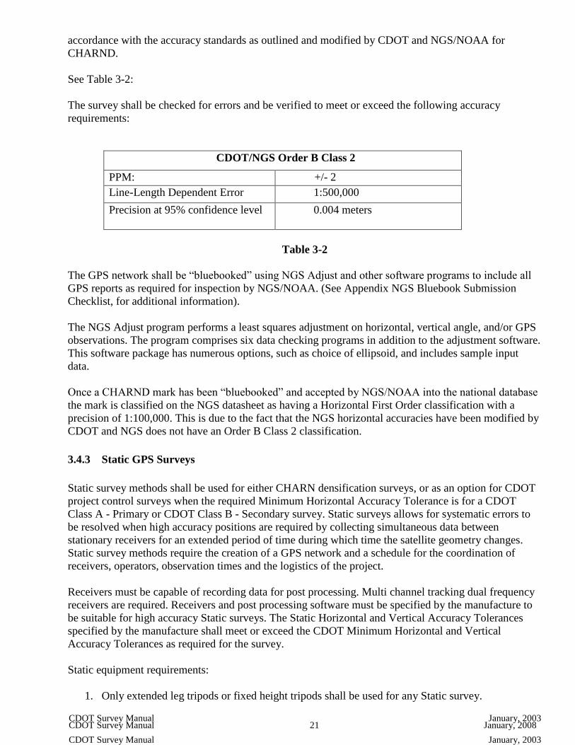
See Table 3-2:
The survey shall be checked for errors and be verified to meet or exceed the following accuracy
requirements:
CDOT/NGS Order B Class 2
PPM: +/- 2
Line-Length Dependent Error 1:500,000
Precision at 95% confidence level
0.004 meters
Table 3-2
The GPS network shall be “bluebooked” using NGS Adjust and other software programs to include all
GPS reports as required for inspection by NGS/NOAA. (See Appendix NGS Bluebook Submission
Checklist, for additional information).
The NGS Adjust program performs a least squares adjustment on horizontal, vertical angle, and/or GPS
observations. The program comprises six data checking programs in addition to the adjustment software.
This software package has numerous options, such as choice of ellipsoid, and includes sample input
data.
Once a CHARND mark has been “bluebooked” and accepted by NGS/NOAA into the national database
the mark is classified on the NGS datasheet as having a Horizontal First Order classification with a
precision of 1:100,000. This is due to the fact that the NGS horizontal accuracies have been modified by
CDOT and NGS does not have an Order B Class 2 classification.
3.4.3 Static GPS Surveys
Static survey methods shall be used for either CHARN densification surveys, or as an option for CDOT
project control surveys when the required Minimum Horizontal Accuracy Tolerance is for a CDOT
Class A - Primary or CDOT Class B - Secondary survey. Static surveys allows for systematic errors to
be resolved when high accuracy positions are required by collecting simultaneous data between
stationary receivers for an extended period of time during which time the satellite geometry changes.
Static survey methods require the creation of a GPS network and a schedule for the coordination of
receivers, operators, observation times and the logistics of the project.
Receivers must be capable of recording data for post processing. Multi channel tracking dual frequency
receivers are required. Receivers and post processing software must be specified by the manufacture to
be suitable for high accuracy Static surveys. The Static Horizontal and Vertical Accuracy Tolerances
specified by the manufacture shall meet or exceed the CDOT Minimum Horizontal and Vertical
Accuracy Tolerances as required for the survey.
Static equipment requirements:
1. Only extended leg tripods or fixed height tripods shall be used for any Static survey.

CDOT Survey Manual 22 January, 2008 CDOT Survey Manual January, 2003
CDOT Survey Manual January, 2003
2. Antennas should have a ground plane in place for Static surveys.
3. Whenever feasible, all antennas for the survey should be of the same make and model.
4. As a guideline CDOT recommends an epoch setting of 1 second and a sync time setting of 15
seconds for all Static surveys.
3.4.4 Fast Static GPS Surveys
Fast Static survey methods shall be used for CDOT project control as an option to Static survey methods
when the required Minimum Horizontal Accuracy Tolerance is for a CDOT Class A - Primary or CDOT
Class B - Secondary survey. Fast Static surveys allow for systematic errors to be resolved when high
accuracy positions are required by collecting simultaneous data between stationary receivers for a
shorter period of time than that of Static surveys. For Fast Static surveys, observation times are typically
8 to 20 minutes and are determined at the time of the field survey by the number of satellites available.
Fast Static survey methods allows for the creation of a GPS network in a “Leap Frog” pattern. Each
baseline between adjacent intervisible control monuments along a transportation corridor must be
observed at least twice.
Receivers must be capable of recording data for post processing. Multi channel tracking dual frequency
receivers are required. Receivers and post processing software must be specified by the manufacture to
be suitable for high accuracy Fast Static surveys. The Fast Static Horizontal and Vertical Accuracy
Tolerances specified by the manufacture shall meet or exceed the CDOT Minimum Horizontal and
Vertical Tolerances as required for the survey.
See Table 3-3:
Typical CDOT Fast Static time duration settings:
Fast Static Observations Minutes of simultaneous observations Minimum number of satellites (SV)
8 minutes 6 SV
15 minutes 5 SV
20 minutes
4 SV (not recommended)
Table 3-3
Fast Static equipment requirements:
1. Only adjustable leg tripods or fixed height tripods shall be used for any Fast Static survey.
2. Whenever feasible, all antennas for the survey should be of the same make and model.
3. Antennas should have a ground plane in place for Fast Static surveys.

CDOT Survey Manual 23 January, 2008 CDOT Survey Manual January, 2003
CDOT Survey Manual January, 2003
4. As a guideline CDOT recommends an epoch setting of 1 second and a sync time setting of 5
seconds for all Fast Static surveys.
3.4.5 RTK GPS Surveys
RTK survey methods shall not be used for any survey project requiring CDOT Minimum Horizontal
Accuracy Tolerances for a CDOT Class A - Primary survey.
RTK surveys are a “Radial” type survey that utilizes two or more receivers with at least one receiver
remaining stationary over a known (reference or base station) project control monument. Other receivers
(rovers) are moved from point to point collecting data in a short amount of time. Reference stations shall
be of the same or higher accuracy as required for the RTK survey. RTK surveys measure the baselines
from the reference station to the roving receivers point. A radio at the reference station broadcast the
position of the reference point to the rovers and the system processes the baselines in “Real Time”
allowing for project coordinate information to be gathered and analyzed during the actual field survey.
Receivers must be capable of being connected to a radio at the reference station for broadcasting and to
a radio at the rover for receiving the reference station broadcast. Multi channel tracking dual frequency
receivers are required. Receivers must be specified by the manufacture to be suitable for RTK surveys.
The RTK Horizontal and Vertical Accuracy Tolerances specified by the manufacture shall meet or
exceed the CDOT Minimum Horizontal and Vertical Accuracy Tolerances as required for the survey.
Care needs to be taken in the field to ensure that the RTK calibration, base station, and project control
points have been set up correctly to allow the RTK data being collected to meet or exceed the CDOT
Minimum Horizontal and Vertical Accuracy Tolerances as required for the survey. (See Existing CDOT
Primary Control Checks, and GPS Reports, for additional information).
Multipath at the reference station and at the rovers, re-initializations and loss of radio link must be kept
to a minimum through project scheduling and organization of the “Best Use” survey method that should
be used for the logistics of the survey project. It should be kept in mind that RTK surveys are just
another tool available to complete a survey project and should only be used only when the CDOT
Minimum Horizontal and Vertical Accuracy Tolerances as required for the survey can be met or
exceeded.
As a guideline CDOT recommends an epoch setting of 1 second.
3.4.6 RTK Site Calibrations
RTK site calibration establishes the relationship between the latitude, longitude, and ellipsoid height
(WGS-84 positions) observed with GPS and the final adjusted local project control northing, easting and
differential leveled elevation (local project control) for each point. The relationship between these
coordinate systems is defined by a series of mathematical parameters. Conversions are applied during
the calibration through a process of least squares that allows for future WGS-84 positions determined by
GPS observations to be converted to local project control coordinates.
The site calibration is performed to obtain the parameters that allow for the conversion from WGS-84
coordinates to local project control coordinates and back again within the data collector in real time. The
local project control coordinate values of the control points are used in the calibration to generate
residuals of the GPS derived observations. The GPS derived coordinates will not be used because known
local project control values already exist for the control points and remain fixed.

CDOT Survey Manual 24 January, 2008 CDOT Survey Manual January, 2003
CDOT Survey Manual January, 2003
To perform a site calibration a minimum of 3 horizontal control points are required, a minimum of 5
horizontal control points are recommended for redundancy. Each of these horizontal control points must
have WGS-84 positions that were observed by either a GPS Static or Fast Static network, as well as
having final adjusted project control coordinate values. To perform a vertical calibration at least 4
vertical control points are required, a minimum of 5 vertical control points are recommended for
redundancy. The vertical calibration is the last part of the calibration to be computed. The vertical
calibration makes the GPS derived orthometric heights (GPS derived elevations) match as closely as
possible with the control differential elevations. (See GPS Derived Orthometric Heights (Elevations), for
additional information).
The site calibrations consist of the following horizontal conversion parameters:
1. Rotation – All of the horizontal points in the calibration are used to calculate the centroid
(geographic center) about which a rotation of all horizontal GPS points are rotated by the same
angular amount.
2. Translation – All of the horizontal points in the calibration have their WGS-84 positions moved
in the same direction and the same distance so they will match closer to the final local project
control coordinates.
3. Scale – A scale factor is calculated using a ratio of the true distances between the local project
control coordinates, and the distances calculated between the GPS derived WGS-84 positions for
the same points. This ratio is the scale factor.
Once the above conversion parameters have been determined and a best fit of the observed GPS derived
WGS-84 positions with the local project control coordinates has been calculated, minor discrepancies
between the GPS derived WGS-84 positions and the local project control coordinates will still exist.
These discrepancies are called the “Residuals” and should be relatively small. The residuals are very
helpful in deciding whether the site calibration is satisfactory or not. It is recommended that these
residuals be no larger than the accuracy tolerance of the Static or Fast Static control survey that was
performed for the control points, and shall not exceed the accuracy tolerance for the RTK survey being
performed.
3.4.7 PPK GPS Surveys
PPK survey methods shall not be used for any survey project requiring CDOT Minimum Horizontal
Accuracy Tolerances for a CDOT Class A – Primary survey.
PPK surveys are a “Radial” type survey similar to an RTK survey, however there is no radio at either the
reference station or the rover to broadcast and the system does not process the baselines in real time.
PPK utilizes two or more receivers with at least one receiver remaining stationary over a known
(reference or base station) project control monument. Other receivers (rovers) are moved from point to
point collecting data in a short amount of time. Reference stations shall be of the same or higher
accuracy as required for the PPK survey. PPK surveys measures the baselines from the reference station
to the roving receivers. Data is collected at both the reference station and at the rover receivers. The data
is downloaded into a GPS processing software program to process the baselines.
Receivers must be capable of collecting data at the reference station and at the rover for downloading
into a GPS processing program. Multi channel tracking dual frequency receivers are required. Receivers
must be specified by the manufacture to be suitable for PPK surveys. The PPK Horizontal and Vertical

CDOT Survey Manual 25 January, 2008 CDOT Survey Manual January, 2003
CDOT Survey Manual January, 2003
Accuracy Tolerances specified by the manufacture shall meet or exceed the CDOT Minimum Horizontal
and Vertical Accuracy Tolerances as required for the survey.
Care needs to be taken in the field to ensure that the PPK calibration, base station, and project control
points have been set up correctly to allow the PPK data being collected to meet or exceed the CDOT
Minimum Horizontal and Vertical Accuracy Tolerances as required for the survey. (See Existing CDOT
Primary Control Checks, and GPS Reports, for additional information).
Multipath at the reference station and at the rovers must be kept to a minimum through project
scheduling and organization of the “Best Use” survey method that should be used for the logistics of the
survey project. It should be kept in mind that PPK surveys are just another tool available to complete a
survey project and should only be used only when the CDOT Minimum Horizontal and Vertical
Accuracy Tolerances as required for the survey can be met or exceeded.
As a guideline CDOT recommends an epoch setting of 1 second and a sync time setting of 5 seconds for
all PPK surveys.
3.4.8 GPS for GIS Mapping Grade Surveys
GIS mapping grade receivers shall not be used to meet any CDOT Horizontal or Vertical Accuracy
Tolerance for a CDOT Class A - Primary, CDOT Class B – Secondary, CDOT Class C - TMOSS or
CDOT Class D - TMOSS survey. A GIS mapping grade receiver is defined for CDOT use as one that is
unable to produce a post processed result within a horizontal accuracy tolerance of 0.050 meters at a
ninety five percent (95%) confidence level.
For information and procedures for GIS mapping please refer to CDOT Corridor GIS Data Standards
and Guidance Manual.
For information on how to obtain a copy of this manual please contact:
Lou Henefeld
CDOT Division Transportation Development/Geographic Information System
1325 South Colorado Boulevard
Denver, Colorado 80222 [email protected]

CDOT Survey Manual 26 January, 2008 CDOT Survey Manual January, 2003
CDOT Survey Manual January, 2003
3.5 Static and Fast Static Network Design
3.5.1 Required Existing Control Monumentation
As stated earlier GPS surveys for all CDOT projects shall be referenced and tied into the CHARN. All
existing control monumentation used to reference or “Tie In” the survey shall be of the same or higher
accuracy as required for the survey.
A minimum of three existing horizontal control monuments shall be used to reference the survey, five
are recommended for redundancy. These existing horizontal control monuments should be located
outside the survey project area to encompass the entire project and provide for good network geometry
throughout the network project area.
A minimum of one existing North American Vertical Datum of 1988 control monument shall be used to
reference the survey, four are recommended for redundancy. If feasible, the existing vertical control
monuments should be located in all four quadrants of the survey and encompass the entire project.
3.5.2 Network Geometry
A network consists of a set of baselines between network points. Networks can be described as having
the following network design:
1. Good Network Geometry – A network design that allows for the network to have computed loop
closures around small closed figures. If the loop misclosure is high it indicates that there is a
problem with at least one of the baselines in the loop. Good network geometry allows other loop
closures to be done that identify and isolate problematic baselines in order that they can be easily
removed.
2. Bad Network Geometry – A network design that allows for loop closers to be computed that will
show a problem exists within the network, but does not allow the problematic baselines to be
identified, isolated and removed.
3. Poor Network Geometry – A network design that allows for coordinates to be computed for the
unknown points, but does not identify any errors that may exist in the network. This will result in
baseline errors going undetected and propagating through the rest of the network.
All GPS networks shall be designed with good network geometry.
For highway corridor control networks that are geometrically long and narrow, it is recommended that
control network points be established outside of the highway corridor on monumentation such as Public
Land Survey System (PLSS) monuments to strengthen the overall network geometry. Permission to
Enter Property Forms shall be completed if required. Once these control network points have been
incorporated into the control network survey they can then be used during RTK calibrations to
strengthen the RTK calibration without the need to re-occupy the monument.
3.5.3 Redundancy of Networks
Redundancy provides for quality control checks of a network and also provides for the desired
confidence in the results obtained from the survey. Each network shall be designed to have a sufficient

CDOT Survey Manual 27 January, 2008 CDOT Survey Manual January, 2003
CDOT Survey Manual January, 2003
amount of redundancy built into the network in accordance with the methods and procedures as required
in this chapter to detect and isolate blunders and/or errors.
Redundancy of a network is achieved by the following:
1. Establish a minimum of four horizontal and vertical primary control monuments for each project
encompassing the entire project.
2. Good network geometry built throughout the entire network
3. A minimum of two independent baselines between each control monument
4. Interconnecting closed loops
5. Repeat baselines measurement
3.5.4 Independent (Non-Trivial) Baselines
Static and Fast Static networks shall be designed as to process at a minimum two independent (non-
trivial) baselines (vectors) between each adjacent control monument. For each session of simultaneous
observations there is one less independent baseline than there are receivers.
An example is given for a control network consisting of four control monuments (CM) observed with
three receivers. There must be five sessions to allow for two independent baselines to be measured
between each control monument. Notice that for each session the receivers are moved to a different
control monument, this allows for additional redundancy to be built into the network.
See Figure 3-1:

CDOT Survey Manual 28 January, 2008 CDOT Survey Manual January, 2003
CDOT Survey Manual January, 2003
Figure 3 – 1
3.5.5 Network Loops
Networks shall contain only closed loops. A closed loop is a series of at least three independent
connecting baselines that start and end on the same point with each loop having at least one baseline in
common with another closed loop to prevent a break in the network. Closed loops shall include observed
baselines from at least two observation sessions.
3.5.6 Twenty Percent Rule
For any two control monuments where the distance between the two control monuments is less than
20% of the total distance as measured along a series of closed connected loops to connect the two
control monuments, there should be at least two independent baselines measured between the two
control monuments.
See Figure 3-2:
Figure 3 – 2

CDOT Survey Manual 29 January, 2008 CDOT Survey Manual January, 2003
CDOT Survey Manual January, 2003
3.6 GPS Planning
3.6.1 Control Monumentation Site Selection
It is critical that before setting any control monumentation the project needs are identified. This is
typically done through the initial scoping of the project to determine the projects limits, factors, and
requirements. After the scoping has been completed the project surveyor shall identify areas to install
CDOT Type 2 control monuments. The following considerations should be taken into account when
choosing a site for installing control monumentation:
1. Sites should be free of vertical obstructions blocking the horizon such as buildings, overhangs,
terrain, trees, fences, utility poles, overhead lines, or any other visible obstructions, non-
obstructed skies 15 degrees above the horizon is best.
2. Sites located close to radio transmitters including cellular phone equipment may disrupt satellite
signal reception.
3. Sites close to large flat surfaces such as signs, fences, glass, or utility boxes should be avoided.
4. Sites shall provide direct line of site between adjacent control monuments.
5. Sites shall not exceed 0.6 mile between adjacent intervisible control monuments.
6. Establish a minimum of four primary control monuments for each project.
7. If feasible, sites should not be disturbed by future construction activities and should be outside
the design toe of slopes and top of cuts for the project.
8. Sites shall be located within the existing highway Right-of-Way.
9. If a site is located outside the existing highway Right-of-Way Permission to Enter Property
Forms shall be completed and an easement for access, installation, and maintenance of the
control monument shall be acquired in CDOT’s name for the benefit of the public for the
purpose of performing a land survey.
After the monumentation sites are identified for installation each site shall be marked and utility locates
called for. (See Chapter 2 – General Procedures, Underground Utility Locates Prior to Installing
Monumentation, for additional information.)
3.6.2 Ephemeris
A GPS ephemeris is the predictions of current satellite positions. Accurate GPS planning is only
accomplished when a current ephemeris is used for the GPS planning.
Current ephemeris can be obtain by the following methods:
1. Downloading the ephemeris from the internet
2. Observing the satellites for a minimum of 15 minutes and downloading from the receiver

CDOT Survey Manual 30 January, 2008 CDOT Survey Manual January, 2003
CDOT Survey Manual January, 2003
Trimble:
http://www.trimble.com/gpsdataresources.shtml
The above link provides information and downloads to obtain a current ephemeris almanac.
3.6.3 Satellite Geometry
A minimum of four satellites are required to survey with GPS. A minimum of five satellites is
recommended. The configuration of the visible satellites the receiver is able to track in relation to each
other will make a significant difference in the data that is being collected. Satellite geometry is
expressed as a numeric value known as Dilution of Precision (DOP). Good satellite geometry will have
small DOP values while poor satellite geometry will have large DOP values. As a guideline DOP values
of six or lower are recommend for CDOT GPS surveys. The ideal satellite geometry is one which has
the visible satellites distributed throughout the sky. Good satellite geometry will yield a higher precision.
Satellite geometry factors that must be considered when planning a GPS survey are:
1. Number of satellites available
2. Minimum elevation angle above the horizon (elevation mask)
3. Obstructions limiting satellite visibility
4. Position Dilution of Precision (PDOP)
5. Vertical Dilution of Precision (VDOP)
6. Horizontal Dilution of Precision (HDOP)
United States Coast Guard, Navigation Center:
http://www.navcen.uscg.gov/
Or call for a 24 hour recorded message: 1-703-313-5907
The above link provides satellite information and important messages for all GPS users.
3.6.4 Elevation Mask
An elevation mask is the lowest elevation above the observer’s horizon that a satellites data is recorded.
Most obstructions below a set elevation mask can be ignored, however multipath can still be produced
from a surface below the set elevation mask. Elevation mask also help to minimize the atmospheric
noise in the data. Satellites that are high in the sky will have less atmospheric noise than satellites low in
the sky and very close to the observer’s horizon. By having an elevation mask set, the noise in the GPS
satellite signals is kept to a minimum. Most GPS processing software allows for the elevation mask to be
raised while processing, but not lowered.
As a guideline CDOT recommends an elevation mask setting of 15 degrees for all GPS surveys.
3.6.5 Weather Conditions
Generally, weather conditions do not affect GPS surveying, however the following conditions must be
considered when planning a GPS survey:
1. GPS Observations should never be conducted during an electrical storm.
2. Significant changes in weather or unusual weather conditions should be noted either in the field
notes, data collector, or receiver.

CDOT Survey Manual 31 January, 2008 CDOT Survey Manual January, 2003
CDOT Survey Manual January, 2003
3. Horizontal and vertical GPS observations can at times be affected by severe snow, hail and rain
storms, high accurate GPS surveys should not be conducted during these periods.
4. Sunspots or magnetic storms can affect GPS observations, care needs to be taken to avoid GPS
surveying during these periods.
5. A five digit weather code is used to summarize the general weather conditions
See Table 3-4:
Weather Codes:
Weather Code 0 1 2
Problem No Problem encountered Problem encountered Not used
Visibility Good (over 15 miles) Fair (7 to 15 miles) Poor (under 7 miles)
Temperature Normal (32o F to 80
o F) Hot (over 80
o F) Cold (under 32
o F)
Cloud Cover Clear (under 20%) Cloudy (20% to 70%) Overcast (over 70%)
Wind Calm (under 5 mph) Moderate (5 to 15 mph) Strong (over 15 mph)
Table 3-4
NOAA Space Weather Now:
http://www.swpc.noaa.gov/SWN/
The above link provides information for space weather activities and warnings.
Sun Spots and Geomagnetic Storm Warnings:
http://members.tripod.com/~Post_119_Gulfport_MS/space.html
The above link provides information of space weather activities and warnings.
NGS GPS Calendar
http://www.ngs.noaa.gov/CORS/Gpscal.shtml
The above link provides information along with current and past GPS calendars.

CDOT Survey Manual 32 January, 2008 CDOT Survey Manual January, 2003
CDOT Survey Manual January, 2003
3.7 GPS Vertical Procedures
3.7.1 Antenna Height Measurement
Blunders in antenna height measurements are a common source of error in GPS surveys. All GPS
surveys are three-dimensional whether the vertical component will be used or not and care needs to be
taken during any GPS survey when measuring the antenna height. Antenna height measurements
determine the height from the survey monument mark to the phase center of the GPS antenna.
There are three types of antenna height measurements done for CDOT GPS surveys:
1. Fixed height tripod rods - To be used for Static, Fast Static, RTK, and PPK surveys. Preferred
over adjustable height tripods for Static and Fast Static surveys.
2. Adjustable height tripods - To be used for Static, Fast Static, RTK, and PPK surveys.
3. Adjustable height rods - To be used only for RTK and PPK surveys.
See Figure 3-3:
Figure 3 – 3
Fixed height tripod rod antenna height measurement procedures:
1. The length of fixed height tripod rods shall be verified each day prior to the beginning of any
observation sessions (See “H” Figure 3-3).

CDOT Survey Manual 33 January, 2008 CDOT Survey Manual January, 2003
CDOT Survey Manual January, 2003
2. Care needs to be taken to ensure the correct antenna type, antenna height measurement type, and
antenna height measurements are entered into the data collector correctly.
3. The following is recorded on the observation log sheet for each observation setup:
a. Antenna type
b. Antenna height measurement type
c. Antenna height measurement in both meters and feet
4. When downloading the data into a GPS post processing software program the following shall be
verified for each observation session:
a. Antenna type
b. Antenna height measurement type
c. Antenna height measurement in both meters and feet
Adjustable height tripod antenna height measurement procedures:
1. The tripod is setup over the survey monument mark and leveled using a precision level prior to
the observations session.
2. Independent antenna heights shall be measured on a slant with a manufacturers approved antenna
height measurement rod in meters at three separate locations on the antenna or the antenna
ground plane, at approximately 120 degrees apart from each measurement (See “S” Figure 3-3).
3. All three antenna height measurements shall not vary +/- 0.003 meters or the tripod setup shall
be checked for level.
4. After checking and re-leveling the tripod, if the antenna height measurements are still not within
the +/- 0.003 meters tolerance the antenna ground plane shall be checked for warping. Ground
planes that are warped more than +/- 0.003 meters shall not be used for any GPS surveys (See
Equipment Maintenance, for additional information).
5. Once the three antenna height measurements are within the +/- 0.003 meter tolerance all three
measurements are recorded on the observation log sheet.
6. The mean of the three antenna height measurements is calculated and recorded on the
observation log sheet.
7. The antenna height measurement is directly measured again in feet and recorded on the
observation log sheet.
8. The mean of the antenna height measurement in meters is verified by comparing the
measurement recorded on the observation log sheet in feet. The two shall not vary by +/- 0.02
feet or the antenna height shall be re-measured.
9. Care needs to be taken to ensure the correct antenna type, antenna height measurement type and
the mean antenna height measurement is entered into the data collector correctly.
10. The following is recorded on the observation log sheet for each observation setup:
a. Antenna type

CDOT Survey Manual 34 January, 2008 CDOT Survey Manual January, 2003
CDOT Survey Manual January, 2003
b. Antenna height measurement type
c. Three antenna height measurements in meters
d. Calculated mean antenna measurement in meters
e. Antenna height measurement in feet
11. When downloading the data into a GPS post processing software program the following shall be
verified for each observation session:
a. Antenna type
b. Antenna height measurement type
c. Mean antenna height measurement is within +/- 0.02 feet of the measurement recorded
on the observation log sheet in feet.
Adjustable height rods antenna height measurement procedures:
1. The length of adjustable height rods including the distance for the addition of the antenna (See
“C” Figure 3-3) shall be verified each day prior to the beginning of any observation sessions.
2. For adjustable height rods that are graduated either in meters, feet, or both, the graduations shall
be verified that the height reading of the rod includes the correct distance for the addition of the
antenna.
3. Adjustable height rods shall be checked continually for lose rods height clamps and tightened as
necessary to avoid the rod height from slipping during the duration of the survey (See Equipment
Maintenance, for additional information).
4. Care needs to be taken to ensure that any changes made in the height of the adjustable height rod
is entered into the data collector and that the correct antenna type, antenna height measurement
type and antenna height measurement is entered into the data collector correctly.
5. When downloading the data from a PPK survey into a GPS post processing software program the
following shall be verified for each observation session:
a. Antenna type
b. Antenna height measurement type
c. Antenna height measurement in both meters and feet
When a station is occupied during two or more back-to-back observation sessions without the equipment
moving to another point, the entire antenna tripod setup shall be taken down, re-setup and re-leveled for
each new observation session.
For stations that are occupied during two of more observations session with the tripod remaining
stationary for the point but with new equipment being used for the observation session (such as antennas
and receivers) the legs of the tripod shall be broken down and the setup re-leveled for an antenna height
substantially different than that of the previous antenna height for each new observation session.
Adjustable antennas height rods shall not be used for any Static or Fast Static survey.

CDOT Survey Manual 35 January, 2008 CDOT Survey Manual January, 2003
CDOT Survey Manual January, 2003
3.7.2 GPS Derived Orthormetric Heights (Elevations)
GPS is a three-dimensional system and errors in the vertical component of GPS measurements will
effect the horizontal positions. Due to this fact all GPS surveys for any type of CDOT survey shall
measure the vertical component even if the vertical is not a requirement for the survey. GPS derived
orthometric heights (elevations) are compiled from ellipsoid heights as determined by GPS observations
and modeled geoid heights using the most current geoid model available.
In order to convert elevations from Global Positioning System (GPS) into ground elevations it is
necessary to apply geoid height corrections as depicted by the latest geoid model for the area of interest.
The National Geodetic Survey (NGS) is the primary source for defining and maintaining geoid models.
NGS updates geoid models on a 3-year cycle (e.g. GEOID 93, GEOID 96, GEOID 99).
The NGS Geoid Page:
http://www.ngs.noaa.gov/GEOID/
The above link provides downloads for the latest NGS/NOAA approved geoid models.
NGS Geodetic Tool Kit
http://www.ngs.noaa.gov/TOOLS/
The above link provides downloads for the latest NGS/NOAA tools.
Trimble Geoid Files:
http://www.trimble.com/support_trl.asp?pt=&Nav=Collection-71
The above link provides downloads for the latest geoid models for Trimble products.
NOAA Guidelines for Establishing GPS-Derived Orthometric Heights
Technical Memorandum Version 4.3:
http://www.ngs.noaa.gov/PUBS_LIB/NGS-58.html
The above link provides information and guidelines for establishing GPS derived ellipsoid heights.
Because of distortions in vertical control networks, lack of high accurate benchmarks and errors in the
geoid height models, GPS derived heights can be difficult to validate. GPS derived heights will
generally be +/- three times worst than the horizontal. However, comparable results between GPS
derived heights and elevations obtained directly by differential leveling techniques are obtainable and
for now is the best way to determine the accuracies of the vertical component in GPS measurements.
See Figure 3-4:
Figure 3 – 4
Due to the fact that highway corridors have GPS control networks established on the ground with GPS
control monuments spaced a maximum distance of 0.6 mile that have latitudes, longitudes, ellipsoid

CDOT Survey Manual 36 January, 2008 CDOT Survey Manual January, 2003
CDOT Survey Manual January, 2003
heights and differential leveled elevations, a geoid model is not required to be imported into an RTK
systems data collector to obtain GPS derived orthometric heights while performing an RTK survey
inside a control network, however it is recommended (See GPS Reports, for additional information). If
no geoid model is used the undulation of the geoid with respect to the ellipsoid is resolved to produce a
simple planar geoid model for the project area. By using the latest geoid model available the GPS
derived heights will be related to the geoid resulting in elevations that will better fit the Earth’s surface.
If accurate elevations are needed outside the control network a differential level loop should be ran to
provide control and checks of the vertical component.
See NGS National Height Modernization Program (NHMP) in this chapter for additional information.
3.7.3 CDOT Class A – Primary Vertical Surveys
All CDOT Class A – Primary vertical surveys performed with GPS shall be performed in accordance
with the methods and procedures as required in this chapter either for a Static or Fast Static survey
meeting the Minimum Vertical Accuracy Tolerance for a CDOT Class A - Primary Survey (See Chapter
5 – Preliminary Surveys, for additional information).
For any CDOT Class A – Primary vertical survey or any primary control monument that requires
accurate elevations be obtained beyond the GPS equipment manufacturers stated vertical accuracy
tolerance, differential leveling shall be used to obtain North American Vertical Datum 1988 elevations
by the methods, procedures, and Minimum Vertical Accuracy Tolerance as required in Chapter 5 –
Preliminary Surveys of this manual.
Unless approved otherwise by the Region Survey Coordinator no CDOT Class A - Primary vertical
survey or primary control monument that requires accurate elevations shall have the elevations
established by GPS derived heights.
For post processing of any CDOT Class A - Primary vertical survey or any Static or Fast Static survey, a
minimal constrained adjustment shall be completed by holding fixed only one three-dimensional control
mark having a published Latitude, Longitude, ellipsoid height and a North American Vertical Datum
1988 elevation of the either the same or higher accuracy than that of the survey being performed. The
minimal constrained adjustment shall verify that the vertical component for the ellipsoid heights are
within an acceptable tolerance for the survey at the ninety five percent (95%) confidence level, or the
survey data shall be checked for blunders, errors and corrected.
Once the minimal constrained adjustment is at an acceptable accuracy tolerance level as required for the
survey, a current geoid model shall be imported into the software and the geoid separations calculated. A
fully constrained adjustment is then performed by incorporating and holding fixed only one additional
differential leveled vertical control mark at a time. For each vertical control mark that is added and held
fixed, the entire network shall be re-adjusted and verified to be within an acceptable vertical tolerance
level for the survey by comparing the GPS derived orthometric heights to the differential leveled
elevations. This process is repeated as many times as needed until all differential leveled vertical control
marks have been incorporated into the survey and are held fixed.
3.7.4 CDOT Class B – Secondary Vertical Surveys
All CDOT Class B – Secondary vertical surveys performed with GPS shall be performed in accordance
with the methods and procedures as required in this chapter either for a Static, Fast Static, RTK or PPK

CDOT Survey Manual 37 January, 2008 CDOT Survey Manual January, 2003
CDOT Survey Manual January, 2003
survey meeting the Minimum Vertical Accuracy Tolerance for a CDOT Class B - Secondary survey
(See Chapter 5 – Preliminary Surveys, for additional information).
For survey monuments that require accurate elevations be obtained beyond the GPS equipment
manufacturers stated vertical accuracy tolerance, 100% of all GPS derived elevations shall be verified or
supplemented with elevations by a more accurate survey method as follows:
1. Differential leveled elevations in accordance with the methods and procedures as required in
Chapter 5 – Preliminary Surveys.
2. Trigonometric elevations by conventional survey methods such as a total station in accordance
with the methods and procedures as required in Chapter 5 – Preliminary Surveys.
3.7.5 CDOT Class C – TMOSS Vertical Surveys
All CDOT Class C – TMOSS vertical surveys performed with GPS shall be performed in accordance
with the methods and procedures as required in this chapter either for a Static, Fast Static, RTK or PPK
survey meeting the Minimum Vertical Accuracy Tolerance for a CDOT Class C – TMOSS survey (See
Chapter 5 – Preliminary Surveys, for additional information).
For TMOSS locations that require accurate elevations be obtained beyond the GPS equipment
manufacturers stated vertical accuracy tolerance, 100% of all GPS derived elevations shall be verified or
supplemented with elevations by a more accurate survey method as follows:
1. Trigonometric elevations by conventional survey methods such as a total station in accordance
with the methods and procedures as required in Chapter 5 – Preliminary Surveys.
2. Differential leveled elevations in accordance with the methods and procedures as required in
Chapter 5 – Preliminary Surveys.
3.7.6 CDOT Class D – TMOSS Vertical Surveys
All CDOT Class D – TMOSS vertical surveys performed with GPS shall be performed in accordance
with the methods and procedures as required in this chapter either for a Static, Fast Static, RTK or PPK
survey meeting the Minimum Vertical Accuracy Tolerance for a CDOT Class D – TMOSS survey (See
Chapter 5 – Preliminary Surveys, for additional information).
For TMOSS locations that require accurate elevations be obtained beyond the GPS equipment
manufacturers stated vertical accuracy tolerance, 100% of all GPS derived elevations shall be verified or
supplemented with elevations by a more accurate survey method as follows:
1. Differential leveled elevations in accordance with the methods and procedures as required in
Chapter 5 – Preliminary Surveys.
2. Trigonometric elevations by conventional survey methods such as a total station in accordance
with the methods and procedures as required in Chapter 5 – Preliminary Surveys.

CDOT Survey Manual 38 January, 2008 CDOT Survey Manual January, 2003
CDOT Survey Manual January, 2003
3.8 GPS Horizontal Procedures
3.8.1 Minimum Horizontal Accuracy Tolerance Table
All GPS surveys for CDOT shall meet the Minimum Horizontal Accuracy Tolerance Table as shown
Chapter 5 – Preliminary Surveys of this manual, for either a CDOT Class A - Primary, Class B -
Secondary, Class C - TMOSS, or Class D - TMOSS survey.
3.8.2 CDOT Class A – Primary Horizontal Surveys
All CDOT Class A – Primary horizontal surveys performed with GPS shall be performed in accordance
with the methods and procedures as required in this chapter for either a Static or Fast Static survey
meeting the Minimum Horizontal Accuracy Tolerance for a CDOT Class A – Primary survey (See
Chapter 5 – Preliminary Surveys, for additional information).
No RTK or PPK survey shall be performed for any CDOT Class A - Primary survey.
For the final processing of any CDOT Class A – Primary horizontal survey a precise ephemeris should
be used. (See Precise Ephemeris, for additional information).
Final adjusted horizontal project control coordinates and ground distances between 68% of all directly
connected intervisible adjacent control monuments should be verified to be within the Minimum
Horizontal Accuracy Tolerance for a CDOT Class A – Primary survey by conventional survey methods
such as a total station with an electronic distance meter. (See GPS Reports, for additional information.)
3.8.3 CDOT Class B – Secondary Horizontal Surveys
All CDOT Class B – Secondary horizontal surveys performed with GPS shall be performed in
accordance with the methods and procedures as required in this chapter either for a Static, Fast Static,
RTK or PPK survey meeting the Minimum Horizontal Accuracy Tolerance for a CDOT Class B –
Secondary survey (See Chapter 5 – Preliminary Surveys, for additional information).
Final RTK or PPK project coordinates for 100% of the following survey monuments shall be verified
(See GPS Reports, for additional information) to be within the Minimum Horizontal Accuracy
Tolerance for a CDOT Class B – Secondary survey by observing each survey monument with a
minimum of two independent RTK or PPK observation sessions (i.e. two separate initializations) with
substantially different GPS constellations (i.e. substantially different times of the day). The base receiver
should reference a different primary project control monument for the second session. If dual bases are
used to reference two primary control monuments 100% of the following survey monuments shall be
observed by a minimum of one RTK or PPK observation session from each base reference station:
1. Secondary Control monuments
2. Photo Control monuments (center and wing points) *
3. Public Land Survey System monuments
4. Right-of-Way monuments
5. Etc.
* Unless approved otherwise by the Region Survey Coordinator all GPS Photo Control monuments
(center and wing points) shall be observed only by Static or Fast Static survey methods and procedures
in accordance with this chapter. (See Chapter 4 – Aerial Surveys, for additional information.)

CDOT Survey Manual 39 January, 2008 CDOT Survey Manual January, 2003
CDOT Survey Manual January, 2003
Final RTK or PPK project coordinates for a minimum of 68%* of the following survey monuments shall
be verified (See GPS Reports, for additional information) to be within the Minimum Horizontal
Accuracy Tolerance for a CDOT Class B – Secondary survey by observing each survey monument with
a minimum of two independent RTK or PPK observation sessions (i.e. two separate initializations) with
substantially different GPS constellations (i.e. substantially different times of the day). The base receiver
should reference a different primary project control monument for the second session. If dual bases are
used to reference two primary control monuments 100% of the following survey monuments shall be
observed by a minimum of one RTK or PPK observation session from each base reference station:
1. Property Boundary monuments
2. Easement monuments
3. Survey Alignment monuments
4. Etc.
* Minimum verification of 68% of the above listed monuments may be increased to 100% by the Region
Survey Coordinator.
3.8.4 CDOT Class C – TMOSS Horizontal Surveys
All CDOT Class C - TMOSS horizontal surveys performed with GPS shall be performed in accordance
with the methods and procedures as required in the chapter for either a Static, Fast Static, RTK or PPK
survey meeting the Minimum Horizontal Accuracy Tolerance for a CDOT Class C – TMOSS survey for
the feature being located (See Chapter 5 – Preliminary Surveys, for additional information).
3.8.5 CDOT Class D – TMOSS Horizontal Surveys
All CDOT Class D – TMOSS horizontal surveys performed with GPS shall be performed in accordance
with the methods and procedures as required in the chapter for either a Static, Fast Static, RTK or PPK
survey meeting the Minimum Horizontal Accuracy Tolerance for a CDOT Class D – TMOSS survey for
the feature being located (See Chapter 5 – Preliminary Surveys, for additional information).
3.8.6 Process for State Plane Coordinate Reduction
For CDOT Class A - Primary surveys, once the final adjusted state plane nothing and easting
coordinates have been calculated the reduction of state plane coordinates to modified project northing
and easting coordinates shall be done in the following order:
1. State plane coordinates shall be in meters.
2. One or more base points are selected to calculate the project latitude, longitude, elevation,
elevation factor, scale factor, combined factor and zone. Either one base point may be selected or
the average of all points may be used. The zone selected shall be either the North, South or
Central zone in accordance with Article 52, CRS, Colorado Coordinate System, and as approved
by the Region Survey Coordinator.
3. Final adjusted state plane coordinates in meters are reduced to modified ground coordinates in
meters using the above calculated factors.

CDOT Survey Manual 40 January, 2008 CDOT Survey Manual January, 2003
CDOT Survey Manual January, 2003
4. Modified ground coordinates in meters (as calculated above) are truncated in both the northing
and easting for an even number value such as 200,000 meters in the northing and 400,000 meters
in the easting.
5. Truncated modified ground coordinates in meters are converted to U.S. Survey Feet in
accordance with Article 52, CRS, Colorado Coordinate System, using the following conversion
factor: One meter equals 3937/1200 feet.
Only after modified ground coordinates in Meters have been truncated shall they be converted to US
survey feet. This allows conversion to and from U.S. Survey Feet to Meters, or Meters to U.S. Survey
Feet without having to truncate the coordinates, and provides a standard procedure for converting state
plane coordinates to modified ground coordinates for CDOT use.

CDOT Survey Manual 41 January, 2008 CDOT Survey Manual January, 2003
CDOT Survey Manual January, 2003
3.9 Project Control Diagram and Land Survey Control Diagram
3.9.1 Project Control diagram
All CDOT Class A – Primary surveys performed by GPS methods shall have a Project Control Diagram
(PCD) completed and filed with the Region Survey Coordinator in accordance with Chapter 5 –
Preliminary Surveys.
3.9.2 Land Survey Control Diagram
All CDOT Class B – Secondary surveys performed by GPS methods shall have a Land Survey Control
Diagram (LSCD) completed and filed with the Region Survey Coordinator and deposited in the records
with the appropriate county clerk’s office in accordance with Chapter 5 – Preliminary Surveys.
Aerial surveys are excluded from this requirement.
3.9.3 TMOSS Surveys
All CDOT Class C – TMOSS and CDOT Class D – TMOSS surveys performed by GPS methods shall
have the final TMOSS survey shown on the Project Control Diagram and/or the Land Survey Control
Diagram in accordance with Chapter 5 – Preliminary surveys.

CDOT Survey Manual 42 January, 2008 CDOT Survey Manual January, 2003
CDOT Survey Manual January, 2003
3.10 NAD83(NSRS2007) National Readjustment
3.10.1 General
On February 10, 2007 NOAA’s National Geodetic Survey (NGS) released its NAD83(NSRS2007)
readjusted horizontal positions and ellipsoid heights of the National Spatial Reference System (NSRS)
to achieve centimeter level consistency with the published NAD83 framework as defined by the latest
Continuously Operating Reference Stations CORS realization. Using high accuracy GPS data only the
readjustment improves the accuracy and consistency of the NSRS and provides a new Local and
Network Accuracy definition for each coordinate.
NGS Readjustment
http://www.ngs.noaa.gov/NationalReadjustment/
The above link provides data and information on the National Readjustment.

CDOT Survey Manual 43 January, 2008 CDOT Survey Manual January, 2003
CDOT Survey Manual January, 2003
3.11 NGS National Height Modernization Program (NHMP)
3.11.1 General
Height Modernization is a program within NOAA's National Geodetic Survey (NGS) that provides
accurate height information by integrating Global Positioning System (GPS) technology with existing
survey techniques. For years, GPS has been used to determine accurate positions (latitude and
longitude), but now, by following Height Modernization standards, specifications and techniques, GPS
can efficiently establish accurate elevations for all types of positioning and navigational needs.
NGS National Height Modernization Program (NHMP)
http://www.ngs.noaa.gov/heightmod/index.shtml
The above link provides information and project specifications to initiate a Height Mod Project or
Program.
NOAA Guidelines for Establishing GPS-Derived Orthometric Heights
Technical Memorandum Version 4.3:
http://www.ngs.noaa.gov/PUBS_LIB/NGS-58.html
The above link provides information and guidelines for establishing GPS derived ellipsoid heights.
See GPS Derived Orthormetric Heights (Elevations) in this chapter for additional information.

CDOT Survey Manual 44 January, 2008 CDOT Survey Manual January, 2003
CDOT Survey Manual January, 2003
3.12 Continually Operating Reference Stations (CORS)
3.12.1 General
The National Geodetic Survey (NGS) coordinates a network of Continuously Operating Reference
Stations (CORS) that provide GPS carrier phase and code range measurements that can be applied
directly to GPS surveys in support of 3-dimensional positioning.
Prior to the NOAA’s NGS National Readjustment in 2007, the CORS system enabled positioning
accuracies that approached a few centimeters (approximately 6 centimeters horizontally) relative to the
National Spatial Reference System (NSRS). In March 2002, NGS upgraded NAD 83 positions and
velocities for all CORS sites so they equal the transformed values of the more recently computed
International Terrestrial Reference Frame of 2000 (ITRF00) positions and velocities.
The National Readjustment, released on February 10, 2008, provides horizontal coordinates and
ellipsoid heights simultaneously readjusted to achieve centimeter consistency with the published
NAD83 framework as defined by the latest CORS realization. Therefore, the NAD83(NSRS2007)
published coordinates and CORS coordinate data are realized as one of the same in accordance with
NGS specifications and accuracy tolerances. NGS will continually update all CORS positions to be
relative to the ITRF00 annually each year.
All CDOT GPS surveys are referenced and tied into CHARN through the NSRS as defined by the
National Geodetic Survey (NGS) National Spatial Reference System (NSRS). Positions obtained by
GPS surveys referencing CORS sites may not be relative to the CHARN as monumented on the ground,
in particular where GPS data did not exist for use in the National Readjustment. The surveyor will need
to take a close look at whether using a CORS station in conjunction with CHARN or CHRAND marks
will help to strengthen the GPS survey or degrade it.
Additionally, ellipsoid heights obtained from CORS may not agree with the CHARN or CHARND. A
NGS Height Modernization should be initiated to undertake simultaneous leveling and GPS activities.
3.12.2 CORS Stations use for Static, Fast Static, RTK, or PPK Surveys
CORS stations shall not be used for performing any CDOT Static, Fast Static, RTK, or PPK survey
unless approved in advance by the Region Survey Coordinator.
Before any CORS station will be approved for use by the Region Survey Coordinator, the following
shall be reviewed and a determination made:
1. The Minimum Horizontal and Vertical Accuracy Tolerance of the GPS survey being performed.
2. The horizontal and vertical accuracy of the CORS station data.
3. How the CORS station is mounted and what it is mounted on.
4. Multipath conditions of the CORS station.
5. The CORS station antenna type.
6. The distance of the CORS station relative to the highway corridor primary control network and
the GPS survey being performed.

CDOT Survey Manual 45 January, 2008 CDOT Survey Manual January, 2003
CDOT Survey Manual January, 2003
7. The overall strength of the geometry of the CORS station relative to the highway corridor
primary control network and the GPS survey being performed.
8. Sync time the CORS station is broadcasting on relative to the sync time of the GPS receivers
performing the survey.
After the above has been reviewed and a determination made to use a CORS station, the stations used
shall be verified as to strengthen the GPS network and not degrade it in relation to the CHARN and/or
CHARND by performing a minimal constrained adjustment of the GPS network.
If the CORS station data is determined to degrade the GPS network the CORS station shall not be used
as part of the network.
NGS/NOAA CORS
http://www.ngs.noaa.gov/CORS/
The above link provides information and downloads of CORS station files.
NGS Cooperative CORS
http://www.ngs.noaa.gov/CORS/
The above link provides information about COOP CORS specifications.

CDOT Survey Manual 46 January, 2008 CDOT Survey Manual January, 2003
CDOT Survey Manual January, 2003
3.13 On-line Positioning User Service (OPUS)
3.13.1 General
The National Geodetic Survey operates the On-line Positioning User Service (OPUS) as a means to
provide GPS users easier access to the National Spatial Reference System (NSRS).
OPUS allows users to submit their GPS data files in RINEX format to NGS, where the data will be
processed to determine a position using NGS computers and software. Each RINEX file that is
submitted will be processed with respect to 3 CORS sites. The sites selected may not be the nearest to
your site but are selected by distance, number of observations, site stability, etc. The position for your
data will be reported back to you via email in both ITRF and NAD83 coordinates as well as UTM and
State Plane Coordinates (SPC) northing and easting.
3.13.2 OPUS use for Static, Fast Static, RTK, or PPK Surveys
The National Geodetic Survey On-line Positioning User Service (OPUS) shall not be used for producing
any final horizontal and/or vertical (X,Y & Z) positions for any CDOT Static, Fast Static, RTK or PPK
survey.
It may be used as a tool for verification of the final horizontal and/or vertical positions (X, Y & Z)
obtain from these types of surveys.

CDOT Survey Manual 47 January, 2008 CDOT Survey Manual January, 2003
CDOT Survey Manual January, 2003
3.14 References
CDOT Survey Manual – CDOT, 1992
CDOT Right of Way Manual – CDOT, July 2002
Geometric Geodetic Accuracy Standards and Specifications for Using GPS Relative Positioning
Techniques – Version 5.0: May 11, 1988, Reprinted with minor corrections: August 1, 1989
Geospatial Positioning Accuracy Standards Part 1: Reporting Methodology – FGDC-STD-007.1-1998,
Federal Geographic Data Committee
Geospatial Positioning Accuracy Standards Part 2: Standards for Geodetic Networks - FGDC-STD-
007.2-1998, Federal Geographic Data Committee
Geospatial Positioning Accuracy Standards Part 3: National Standard for Spatial Data Accuracy -
FGDC-STD-007.3-1998, Federal Geographic Data Committee
Geospatial Positioning Accuracy Standards Part 4: Standards for Architecture, Engineering,
Construction (A/E/C) and Facility Management - FGDC-STD-007.4-2002, Federal Geographic Data
Committee
NGS Draft GPS Survey Manual – Last updated on May 8, 2000
Input Formats and Specifications of the National Geodetic Survey Data Base, The NGS "Bluebook" –
Last update on March 29, 2002
Policy of the National Ocean service regarding the incorporation of Geodetic Data of other
organizations into the National Geodetic Survey database – September 1994, Addendum 1 approved by
the NGS Executive Steering Committee March 26, 1977
Standards and Guidelines for Cadastral Surveys Using Global Positioning System Methods – Bureau of
Land Management, May 9, 2001 Version 1.0
Global Positioning System (GPS) Survey Specifications – California Department of Transportation,
Survey Manual, Chapter 6, June 1997
Control Surveys - California Department of Transportation, Survey Manual, Chapter 9, May 1998
Survey and Mapping Product Training, GPSurvey – Trimble, Part Number: 33143-10 Edition A,
Copyright 1998, Trimble Navigation
Real-Time Kinematic Surveying Training Manual – Trimble, Part Number: 33142-40 Revision A,
September 2001, Copyright 1998-2001, Trimble Navigation Limited
Introduction to Real Time Surveying, Product Training – Trimble, Part Number: 33142-20, Revision A,
Copyright 1998-1999, Trimble Navigation Limited
An Evaluation of the High Accuracy Reference Network Relative to the Continuously Operating
Reference Stations – by Kathryn O. Milbert, NGS/NOS/NOAA.