Embed Size (px)
Citation preview
7/27/2019 Surpass Hit 7025 Td
http://slidepdf.com/reader/full/surpass-hit-7025-td 1/93
1/93 IPT NGM
W. Kaiser Technical Description SURPASS hiT 7025June 05, 2008 / Issue 06
Copyright 2008 Nokia Siemens Networks. All rights reserved.
Technical Description
SURPASS hiT 7025Issue 06
7/27/2019 Surpass Hit 7025 Td
http://slidepdf.com/reader/full/surpass-hit-7025-td 2/93
2/93 IPT NGMW. Kaiser
Technical Description SURPASS hiT 7025June 05, 2008 / Issue 06
Copyright 2008 Nokia Siemens Networks. All rights reserved.
The information contained in this document is confidential and the property of Nokia Siemens Networks and is suppliedwithout liability for errors or omissions. It is subject to change without notice and describes only the product defined in
the introduction of this documentation. This documentation is intended for the use of Nokia Siemens Networkscustomers only for the purposes of the agreement under which the document is submitted, and no part of it may beused, reproduced, modified or transmitted in any form or means without the prior written permission of Nokia SiemensNetworks. Nokia Siemens Networks welcomes customer comments as part of the process of continuous developmentand improvement of the documentation.
This Technical Description is provided as a generic descriptive document only. It does not include any legally bindingstatement. The product features, and details thereof, discussed in this Technical Description may include those thatprove to be temporarily or permanently unavailable. Nokia Siemens Networks reserves the right to alter without noticethe specification, design, price or conditions of supply of any product or service.
Nokia Siemens Networks will correct errors in this documentation as soon as possible. IN NO EVENT WILL NOKIASIEMENS NETWORKS BE LIABLE FOR ERRORS IN THIS DOCUMENTATION OR FOR ANY DAMAGES,INCLUDING BUT NOT LIMITED TO SPECIAL, DIRECT, INDIRECT, INCIDENTAL OR CONSEQUENTIAL OR ANYLOSSES, SUCH AS BUT NOT LIMITED TO LOSS OF PROFIT, REVENUE, BUSINESS INTERRUPTION, BUSINESSOPPORTUNITY OR DATA,THAT MAY ARISE FROM THE USE OF THIS DOCUMENT OR THE INFORMATION IN IT.
This documentation and the product it describes are considered protected by copyrights and other intellectual propertyrights according to the applicable laws.
The wave logo is a trademark of Nokia Siemens Networks Oy. Nokia is a registered trademark of Nokia Corporation.Siemens is a registered trademark of Siemens AG.
Other product names mentioned in this document may be trademarks of their respective owners, and they arementioned for identification purposes only.
Copyright © Nokia Siemens Networks 2008. All rights reserved. The copyright and the foregoing restrictions onreproduction and use extend to all media in which the information may be embodied.
History of Changes
Control Date Author Comments
04 18.06.2007 Rainer Koster Rebranded to NSN layout
05 Feb 27, 2008 Th. Jost New SW license structure added
06 Jun 05, 2008 Rainer Koster New 4x STM-1 board and enhanced temperature variantadded
7/27/2019 Surpass Hit 7025 Td
http://slidepdf.com/reader/full/surpass-hit-7025-td 3/93
3/93 IPT NGMW. Kaiser
Technical Description SURPASS hiT 7025June 05, 2008 / Issue 06
Copyright 2008 Nokia Siemens Networks. All rights reserved.
Contents
0H1. Introduction ............................................................................187H8
1H1.1 Editorials ........................................................................................................... 188H8 2H1.2 Next Generation SDH ....................................................................................... 189H8 3H1.3 SURPASS hiT 70 series ................................................................................... 190H9
4H2. SURPASS hiT 7025 Overview.............................................191H11
5H2.1 Overview......................................................................................................... 192H11 6H2.1.1 Physical Structure........................................................................................... 193H12 7H2.1.2 Cross Connection and Switching Capability ................................................... 194H13 8H
2.1.3 Line/Service Interface .....................................................................................195H
13 9H2.2 Data Capabilities............................................................................................. 196H14 10H2.3 Advanced Data Service Support..................................................................... 197H14 11H2.3.1 IEEE 802.1Q (VLAN) ...................................................................................... 198H14 12H2.3.2 Input Information Rating Limiting .................................................................... 199H15 13H2.3.3 Class of Service.............................................................................................. 200H15 14H2.3.4 GFP Data Encapsulation ................................................................................ 201H15 15H2.3.5 Virtual Concatenation and LCAS .................................................................... 202H15 16H2.3.6 RSTP Based Protection.................................................................................. 203H16 17H2.3.7 L2 Multicast Function...................................................................................... 204H16 18H2.3.8 Ethernet Transport Schemes.......................................................................... 205H17
19H2.4 Network Protections........................................................................................ 206H18 20H2.5 Main Features & Strengths ............................................................................. 207H19 21H2.5.1 Flexibility ......................................................................................................... 208H19 22H2.5.2 Reliability......................................................................................................... 209H19 23H2.5.3 Modularity and Scalability ............................................................................... 210H19 24H2.5.4 Ease of use..................................................................................................... 211H19 25H2.5.5 Data Handling Capabilities.............................................................................. 212H20
26H3. System Application ..............................................................213H21
27H3.1 Networking Capability ..................................................................................... 214H21 28H3.1.1 Termination and Multiplexing (TM) ................................................................. 215H21 29H3.1.2 Hubbing and Local Cross Connect ................................................................. 216H21 30H3.1.3 Linear.............................................................................................................. 217H22 31H3.1.4 Ring................................................................................................................. 218H22 32H3.1.5 Multiple Ring Closure...................................................................................... 219H23
33H3.2 Ethernet Service Applications......................................................................... 220H23
34H4. System Description..............................................................221H25
35H4.1 Physical Structure and Module Construction.................................................. 222H25 36H4.1.1 Chassis Slot Naming....................................................................................... 223H25 37H4.1.2 SURPASS hiT 7025 interface options ............................................................ 224H26
38H
4.2 Power Supply..................................................................................................225H
27 39H4.3 FAN 226H27 40H4.4 System Controller (SC)................................................................................... 227H27
7/27/2019 Surpass Hit 7025 Td
http://slidepdf.com/reader/full/surpass-hit-7025-td 4/93
4/93 IPT NGMW. Kaiser
Technical Description SURPASS hiT 7025June 05, 2008 / Issue 06
Copyright 2008 Nokia Siemens Networks. All rights reserved.
41H4.5 System Interface Panel (SI)............................................................................ 228H27 42H
4.6 Cross-Connect Switching (CC).......................................................................229H
27 43H4.7 SDH Interfaces................................................................................................ 230H28 44H4.7.1 1x STM-4 Interface Board............................................................................... 231H28 45H4.7.2 2× STM-1 Interface Board............................................................................... 232H28 46H4.7.3 4× STM-1 Interface Board............................................................................... 233H28 47H4.7.4 2× STM-1E (W/P) Interface............................................................................. 234H28
48H4.8 PDH and Data Service Interfaces................................................................... 235H29 49H4.8.1 8x FE/L2 Service Interface Card..................................................................... 236H29 50H4.8.2 8x FE/T Service Interface Card....................................................................... 237H32 51H4.8.3 1x GE/T Service Interface Board .................................................................... 238H34 52H4.8.4 3× E3/DS3 (W/P) Interface Card..................................................................... 239H35 53H
4.8.5 21× E1 (W/P) Interface Card...........................................................................240H
36 54H4.9 Optical Amplifier.............................................................................................. 241H36 55H4.10 User Channel (F1) .......................................................................................... 242H39 56H4.11 Engineering Order Wire (EOW) ...................................................................... 243H39 57H4.12 Miscellaneous Discrete Input/Output (MDI/MDO)........................................... 244H40 58H4.13 Introduction to Software licensing................................................................... 245H41 59H4.13.1 General Structure of new SW items................................................................ 246H41 60H4.13.2 Software license structure of SURPASS hiT 7025 ......................................... 247H42
61H5. Protection and Redundancy.................................................248H44
62H5.1 Network Protection.......................................................................................... 249H44 63H5.1.1 MS-SPRing ..................................................................................................... 250H44 64H5.1.2 MSP ................................................................................................................ 251H44 65H5.1.3 SNCP.............................................................................................................. 252H45 66H5.1.4 LCAS............................................................................................................... 253H45 67H5.1.5 Ethernet Shared Protection Ring .................................................................... 254H46 68H5.1.6 Multiple Layers Protection............................................................................... 255H46
69H5.2 Equipment Redundancy and Protection ......................................................... 256H46 70H5.2.1 Redundant Power Supply ............................................................................... 257H46 71H5.2.2 Redundant Cross-Connect ............................................................................. 258H46 72H5.2.3 Electrical Interface Module Protection ............................................................ 259H47 73H5.2.4 Protection under Abnormal Condition............................................................. 260H47 74H5.2.5 Software Fault Tolerance................................................................................ 261H47 75H5.2.6 Data Security .................................................................................................. 262H48
76H6. Technical Specification ........................................................263H49
77H6.1 Multiplexing Structure ..................................................................................... 264H49 78H6.2 SDH Overhead................................................................................................ 265H51 79H6.3 Interface Types ............................................................................................... 266H52 80H6.3.1 Electrical Interfaces......................................................................................... 267H53 81H6.3.2 Optical Interfaces............................................................................................ 268H53 82H6.3.3 Management and Maintenance Interface ....................................................... 269H55
83H6.4 Interface Performance Specifications ............................................................. 270H55 84H6.4.1 Optical Interface Performances ...................................................................... 271H55 85H6.4.2 STM-1 Optical Interface Performance ............................................................ 272H56 86H6.4.3 STM-4 Optical Interface Performance ............................................................ 273H57
7/27/2019 Surpass Hit 7025 Td
http://slidepdf.com/reader/full/surpass-hit-7025-td 5/93
5/93 IPT NGMW. Kaiser
Technical Description SURPASS hiT 7025June 05, 2008 / Issue 06
Copyright 2008 Nokia Siemens Networks. All rights reserved.
87H6.4.4 STM-16 Optical Interface Performance .......................................................... 274H58 88H
6.4.5 Multi-rate CWDM interface Optical Performance............................................275H
60 89H6.4.6 2.5G DWDM interface Optical Performance................................................... 276H61 90H6.4.7 GE Optical Transmitter and Receiver Interfaces ............................................ 277H62 91H6.4.8 Electrical Interface Performances................................................................... 278H65 92H6.4.9 Timing and Synchronization Performance...................................................... 279H67 93H6.4.10 Jitter Performance........................................................................................... 280H68 94H6.4.11 STM-N Interface Output Jitter ......................................................................... 281H68
95H6.5 Timing ............................................................................................................. 282H71 96H6.6 Power Source ................................................................................................. 283H71 97H6.6.1 Power Supply.................................................................................................. 284H71 98H6.6.2 Power Consumption........................................................................................ 285H72 99H6.6.3 Cooling............................................................................................................ 286H72
100H6.7 Mechanical Structure ...................................................................................... 287H72 101H6.8 Environment Requirements ............................................................................ 288H73 102H6.8.1 Enhanced Temperature Variant...................................................................... 289H73
103H6.9 Electromagnetic Compatibility......................................................................... 290H73 104H6.10 Vibration Tests................................................................................................ 291H74 105H6.10.1 Shipping Test .................................................................................................. 292H74 106H6.10.2 Office Test....................................................................................................... 293H75
107H6.11 Alarms and Events.......................................................................................... 294H75 108H6.11.1 Alarm Types.................................................................................................... 295H75 109H6.11.2 Alarm Severity Level ....................................................................................... 296H76 110H6.11.3 Alarm Reports................................................................................................. 297H76 111H6.11.4 Events............................................................................................................. 298H76
112H7. Standard Compliance ..........................................................299H78
113H8. Appendix 1: Definitions and Abbreviations ..........................300H81
114H9. Appendix 2: Basis Technologies..........................................301H88
115H9.1 Generic Framing Procedure (GFP)................................................................. 302H88 116H9.2 Virtual Concatenation (VCat) .......................................................................... 303H90 117H
9.3 Link Capacity Adjustment Scheme (LCAS) ....................................................304H
91 118H9.4 Ethernet Functions and Services.................................................................... 305H91
119H10. Appendix 3: Related Documents .........................................306H93
7/27/2019 Surpass Hit 7025 Td
http://slidepdf.com/reader/full/surpass-hit-7025-td 6/93
6/93 IPT NGMW. Kaiser
Technical Description SURPASS hiT 7025June 05, 2008 / Issue 06
Copyright 2008 Nokia Siemens Networks. All rights reserved.
List of Figures
120HFigure 1 - Future Traffic Growth.................................................................................................... 307H9
121HFigure 2 - SURPASS hiT 7025 chassis ...................................................................................... 308H11
122HFigure 3 – SURPASS hiT 7025 Physical Structure..................................................................... 309H12
123HFigure 4 - Three Ethernet data transmission methods in SURPASS hiT 7025 ring ................... 310H18
124HFigure 5 - SURPASS hiT 7025 termination and multiplexing capability ..................................... 311H21
125HFigure 6 - SURPASS hiT 7025 termination and multiplexing capability ..................................... 312H22
126HFigure 7 - SURPASS hiT 7025 linear network configuration ...................................................... 313H22
127HFigure 8 - SURPASS hiT 7025 2-fiber MS-SPRing application.................................................. 314H23
128HFigure 9 - Multiple Ring closure at a single SURPASS hiT 7025 node ...................................... 315H23
129HFigure 10 - SURPASS hiT 7025 Chassis view ........................................................................... 316H25
130HFigure 11 - SURPASS hiT 7025 chassis slot naming................................................................. 317H26
131HFigure 12 - SURPASS hiT 7025 Cards List ................................................................................ 318H26
132HFigure 13 - Functional block diagram of 2× STM-1E (W/P) card protection ............................... 319H29
133HFigure 14 - 8× FE/L2 card functional block diagram ................................................................... 320H30
134HFigure 15 - 8× FE/L2 interface card external interfaces.............................................................. 321H31
135HFigure 16 - 8× FE/L2 card LEDs ................................................................................................. 322H31
136H
Figure 17 - 8× FE/T card functional block diagram.....................................................................323H
32 137HFigure 18 - 8× FE/T interface card external interfaces................................................................ 324H33
138HFigure 19 - 8× FE/T card LEDs ................................................................................................... 325H33
139HFigure 20 - 1× GE/T service board module functional block diagram......................................... 326H34
140HFigure 21 - Functional block diagram of 3× E3/DS3 (W/P) card protection................................ 327H35
141HFigure 22 – OA module functional building block diagram ......................................................... 328H37
142HFigure 23 – OA module safty procedure..................................................................................... 329H38
143HFigure 24 – OA card external interfaces ..................................................................................... 330H39
144HFigure 25 – OA card LEDs.......................................................................................................... 331H39
145HFigure 26 –External XOW box .................................................................................................... 332H40
146HFigure 27: Software license structure in Next Generation Metro................................................ 333H41
147HFigure 28: Software license structure of SURPASS hiT 7025.................................................... 334H43
148HFigure 29 - Cross-Connect Multiplexing Structure (ITU-T G.707) .............................................. 335H49
149HFigure 30 - Terminated Mapping Structure................................................................................. 336H50
150HFigure 31 - Payload Mapping ...................................................................................................... 337H50
151HFigure 32 – SURPASS hiT 7025 supported SDH overhead process......................................... 338H52
152HFigure 33 – SURPASS hiT 7025 Interface Types....................................................................... 339H52
153HFigure 34 - SURPASS hiT 7025 optical service interfaces supported........................................ 340H54
154HFigure 35 - STM-N Optical Interface Parameters and Application Codes.................................. 341H55
7/27/2019 Surpass Hit 7025 Td
http://slidepdf.com/reader/full/surpass-hit-7025-td 7/93
7/93 IPT NGMW. Kaiser
Technical Description SURPASS hiT 7025June 05, 2008 / Issue 06
Copyright 2008 Nokia Siemens Networks. All rights reserved.
155HFigure 36 - SURPASS hiT 7025 STM-1Optical Interface Specifications.................................... 342H56
156HFigure 37 - SURPASS hiT 7025 STM-4 Optical Interface Specifications................................... 343H58
157HFigure 38 - SURPASS hiT 7025 STM-16 Optical Interface Specifications................................. 344H59
158HFigure 39 - SURPASS hiT 7025 CWDM Optical Interface Specifications .................................. 345H60
159HFigure 40 - SURPASS hiT 7025 DWDM Optical Interface Specifications .................................. 346H61
160HFigure 41 - SURPASS hiT 7025 DWDM Wavelenthes............................................................... 347H62
161HFigure 42 - 1000 Base-SX transmitter interface parameters ...................................................... 348H63
162HFigure 43 - 1000 Base-SX receiving interface parameters......................................................... 349H63
163HFigure 44 - 1000 Base-LX Transmitter interface parameters ..................................................... 350H64
164HFigure 45 - 1000 Base-LX receiver interface parameters........................................................... 351H65
165HFigure 46 - 2048 kbit/s Electrical Interface Parameters.............................................................. 352H66
166HFigure 47 - Electrical Interface Output Signals Bit Rate Allowable Deviation............................. 353H66
167HFigure 48 - Electrical Interface Allowable Input Attenuation ....................................................... 354H67
168HFigure 49 - Electrical Interface Allowable Input Port Frequency Deviation................................. 355H67
169HFigure 50 - Electrical Interface Input Port Anti-interference Capability....................................... 356H67
170HFigure 51 - Timing Output Jitter .................................................................................................. 357H68
171HFigure 52 - Internal Timing Source Output Frequency ............................................................... 358H68
172HFigure 53 - STM-1/-4/-16 Interface Output Jitter......................................................................... 359H69
173HFigure 54 - STM-1 Interface Jitter Tolerance.............................................................................. 360H69
174HFigure 55 - STM-4 Interface Jitter Tolerance.............................................................................. 361H70
175HFigure 56 - STM-16 Interface Jitter Tolerance............................................................................ 362H70
176HFigure 57 - PDH mapping jitter generation specification ............................................................ 363H70
177HFigure 58 - SURPASS hiT 7025 PDH interface combined jitter generation spec....................... 364H71
178HFigure 59 - SURPASS hiT 7025 Environment Requirements..................................................... 365H73
179HFigure 60 - SURPASS hiT 7025 Electromagnetic Compatibility Requirements ......................... 366H74
180HFigure 61 - Shipping Test Standards .......................................................................................... 367H74
181HFigure 62 - Office test standards................................................................................................. 368H75
182HFigure 63 - Management Events................................................................................................. 369H77
183HFigure 64 - Hardware Events ...................................................................................................... 370H77
184HFigure 65 - Software Events........................................................................................................ 371H78
185HFigure 66 - GFP mapping............................................................................................................ 372H89
186HFigure 67 - Comparison between GFP and PPP........................................................................ 373H90
7/27/2019 Surpass Hit 7025 Td
http://slidepdf.com/reader/full/surpass-hit-7025-td 8/93
8/93 IPT NGMW. Kaiser
Technical Description SURPASS hiT 7025June 05, 2008 / Issue 06
Copyright 2008 Nokia Siemens Networks. All rights reserved.
1. Introduction
1.1 Editorials
This document is a technical description for the product SURPASS hiT 7025. Thetechnical descriptions of other products of the SURPASS hiT 70 series are alsoavailable. This document is not a marketing document. The target of this document isto inform on detail about the product, product features and the application in thenetwork environment.
It is not a document for advertisement purposes but it is useful to inform our customer in detail in the after sales period. For marketing and advertisement related productinformation please contact the sales department.
If the reader is looking for information on the basis technologies please refer to 374H9375H Appendix 2: Basis Technologies.
1.2 Next Generation SDH
For almost two decades, Synchronous Digital Hierarchy (SDH) has been the preferredtransport technology over optical fibers. SDH is the dominant transport protocol in
virtually all long-haul networks (voice and data) as well as in metro networks that wereoriginally developed for voice traffic. As a resilient, well-understood transportmechanism, SDH has stood the test of time. Its reliability is unsurpassed. The ability of SDH to support 50-msec switching to backup paths, combined with extensiveperformance monitoring features for carrier-class transport.
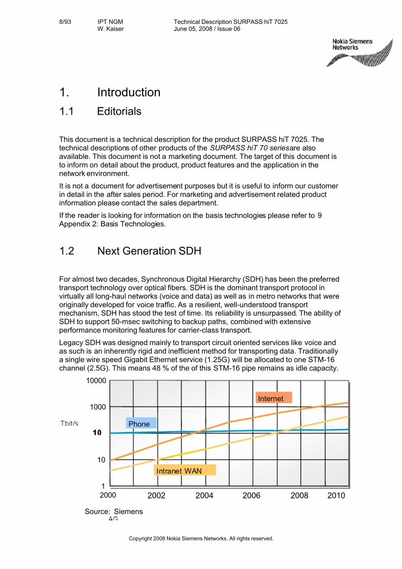
Legacy SDH was designed mainly to transport circuit oriented services like voice andas such is an inherently rigid and inefficient method for transporting data. Traditionallya single wire speed Gigabit Ethernet service (1.25G) will be allocated to one STM-16channel (2.5G). This means 48 % of the of this STM-16 pipe remains as idle capacity.
1
10
1000
10000
2000 2002 2004 2006 2008 2010
Phone
Internet
Intranet WAN
Source: Siemens
7/27/2019 Surpass Hit 7025 Td
http://slidepdf.com/reader/full/surpass-hit-7025-td 9/93
9/93 IPT NGMW. Kaiser
Technical Description SURPASS hiT 7025June 05, 2008 / Issue 06
Copyright 2008 Nokia Siemens Networks. All rights reserved.
Figure 1 - Future Traffic Growth
The phenomenal growth in bandwidth, connectivity and content generated by theInternet, Intranet and broadband applications, has made native data transfer a veryimportant criteria for telecommunication infrastructure (see Figure 1). Ethernet hasbecome the de facto standard for enterprise networks. In Storage Area Networks(SAN), ESCONTM, FICONTM and Fiber Channel are by far today‘s most dominatingtechnology as well.
The solution is Next Generation SDH—technology that transforms rigid, circuit-orientedSDH networks to a universal transport mechanism that is optimized for both voice anddata. The technology enables carriers to keep up with growing demands for bandwidth,to efficiently carry both streaming and bursty traffic, and adapt to constantly changingtraffic patterns. Multiple protocols and thus services are supported: from basic TDMvoice, Ethernet, as well as SAN.
1.3 SURPASS hiT 70 series
Siemens has introduced a new range of equipment that makes the promise of NextGeneration SDH a reality: the SURPASS hiT 70 series. This platform provides theflexibility of true packet switching and Ethernet transport, while operating with theinherent reliability of SDH. Multiple network elements are integrated and consolidated
into a single compact unit. The efficiency of this approach, together with extensive useof highly integrated components allows the SURPASS hiT 70 series to be offered atlower costs than current solutions.
Data + Voice = SURPASS hiT 70 series
In order to address the varying needs and requirements of carrier‘s carrier, carrier andenterprise, the SURPASS hiT 70 series consists of a diverse range of products,namely:
•SURPASS hiT 7080 ADM / CC multiple STM-64
•SURPASS hiT 7070 SC/DC ADM / CC, multiple STM-64
•SURPASS hiT 7060 HC ADM 64, multiple STM-16
•SURPASS hiT 7060 ADM, multiple STM-16
•SURPASS hiT 7050 CC ADM 16, multiple STM 4
•SURPASS hiT 7050 FP ADM, multiple STM 1/4
•SURPASS hiT 7035 ADM 16/4, multiple STM 4 upgradeable to STM16
•SURPASS hiT 7030 ADM 4/1 modular
7/27/2019 Surpass Hit 7025 Td
http://slidepdf.com/reader/full/surpass-hit-7025-td 10/93
10/93 IPT NGMW. Kaiser
Technical Description SURPASS hiT 7025June 05, 2008 / Issue 06
Copyright 2008 Nokia Siemens Networks. All rights reserved.
•SURPASS hiT 7025 ADM 16/4/1, multiple STM 1/4 upgradeable to
STM16
•SURPASS hiT 7020 ADM 4/1 single board CPE
This Technical Description covers SURPASS hiT 7025, only. For detailed descriptionof the other product please refer to 376H10 377H Appendix 3: Related Documents.
7/27/2019 Surpass Hit 7025 Td
http://slidepdf.com/reader/full/surpass-hit-7025-td 11/93
11/93 IPT NGMW. Kaiser
Technical Description SURPASS hiT 7025June 05, 2008 / Issue 06
Copyright 2008 Nokia Siemens Networks. All rights reserved.
2. SURPASS hiT 7025 Overview
2.1 Overview
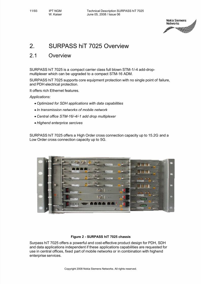
SURPASS hiT 7025 is a compact carrier class full blown STM-1/-4 add-drop-multiplexer which can be upgraded to a compact STM-16 ADM.
SURPASS hiT 7025 supports core equipment protection with no single point of failure,and PDH electrical protection.
It offers rich Ethernet features.
Applications:
• Optimized for SDH applications with data capabilities
• In transmission networks of mobile network
• Central office STM-16/-4/-1 add drop multiplexer
• Highend enterprice sercives
SURPASS hiT 7025 offers a High Order cross connection capacity up to 15.2G and aLow Order cross connection capacity up to 5G.
Figure 2 - SURPASS hiT 7025 chassis
Surpass hiT 7025 offers a powerful and cost-effective product design for PDH, SDH
and data applications independent if these applications capabilities are requested for use in central offices, fixed part of mobile networks or in combination with highendenterprise services.
7/27/2019 Surpass Hit 7025 Td
http://slidepdf.com/reader/full/surpass-hit-7025-td 12/93
12/93 IPT NGMW. Kaiser
Technical Description SURPASS hiT 7025June 05, 2008 / Issue 06
Copyright 2008 Nokia Siemens Networks. All rights reserved.
SURPASS hiT 7025 supports the complete range of PDH and SDH interfaces ranging
from E1, E3/DS3, STM-1 el./opt. up to STM-4 and even STM-16. It provides a full suiteof SDH functions including mapping, multiplexing, cross-connection and variousprotection schemes.
SURPASS hiT 7025 has a modular and scalable design, enabling a pay-as-you-growdeployment plan. The system can be initially deployed as a low cost, modest capacitysystem, and then enlarged to a high capacity, multi-service system. A large variety of service modules ensure a cost-effective match with service demands of today whileretaining superior flexibility to meet future service requirements.
Its advance software architecture design results in a highly fault-tolerant system.Combined with built-in hardware redundancies, SURPASS hiT 7025 achieves carrier-class reliability with 99.999% availability.
The system is fully compliant with ITU-T and/or IEEE standards, and is inter-operablewith other standards-based SDH, multi-service transport, and data communicationproducts.
Utilizing SURPASS hiT 7025 in combination with the multi-service capabilities of Siemens TNMS network management system, service providers can cost-effectivelygrow their embedded base networks or launch new networks
2.1.1 Physical Structure
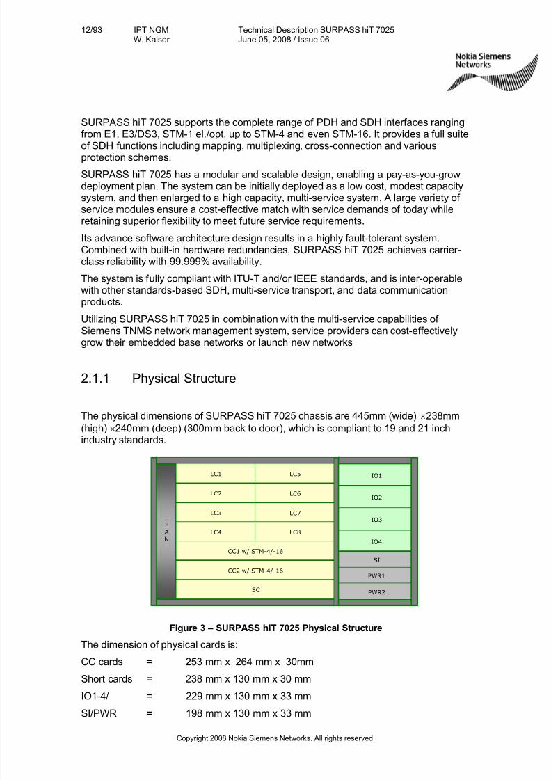
The physical dimensions of SURPASS hiT 7025 chassis are 445mm (wide) × 238mm
(high) × 240mm (deep) (300mm back to door), which is compliant to 19 and 21 inchindustry standards.
Figure 3 – SURPASS hiT 7025 Physical Structure
The dimension of physical cards is:
CC cards = 253 mm x 264 mm x 30mm
Short cards = 238 mm x 130 mm x 30 mmIO1-4/ = 229 mm x 130 mm x 33 mm
SI/PWR = 198 mm x 130 mm x 33 mm
CC2 w/ STM-4/-16
F
A
N
CC1 w/ STM-4/-16
LC7
SC
LC3
IO4
IO1
IO2
IO3
SI
PWR1
PWR2
LC5LC1
LC6LC2
LC8LC4
CC2 w/ STM-4/-16
F
A
N
CC1 w/ STM-4/-16
LC7
SC
LC3
IO4
IO1
IO2
IO3
SI
PWR1
PWR2
LC5LC1
LC6LC2
LC8LC4
7/27/2019 Surpass Hit 7025 Td
http://slidepdf.com/reader/full/surpass-hit-7025-td 13/93
13/93 IPT NGMW. Kaiser
Technical Description SURPASS hiT 7025June 05, 2008 / Issue 06
Copyright 2008 Nokia Siemens Networks. All rights reserved.
FAN = 246 mm x 225 mm x 36 mm
All external interfaces have front access.
2.1.2 Cross Connection and Switching Capability
SURPASS hiT 7025 supports two types of cross connection and switching capabilities:
ADM-4/-1: 7.2G/2.5G CC with 1x STM-4/-1 line interface:
•HOCC: (7.2G)
• LOCC: (2.5G)
ADM-16/-4: 15.2G/5 CC with 1x STM-16/-4 line interface:
•HOCC: 15.2G
• LOCC: 5G
2.1.3 Line/Service Interface
SURPASS hiT 7025 provides the following line interfaces:
1) SDH: 1× STM-4 Optical Line Interface Board
2) SDH: 2× STM-1 Optical Interface Board
3) SDH: 4× STM-1 Optical Interface Board
4) SDH: 2× STM-1E (W/P) Electrical Interface Card
5) SDH: 2× STM-1E PaddleCard
6) PDH: 3× E3/DS3 (W/P) interface card
7) PDH: 3× E3/DS3 Paddle
8) PDH: 21× E1 (W/P) client interface card
9) PDH: 21× E1 75ohm Paddle
10) PDH: 21× E1 120ohm Paddle
11) IP/Ethernet: 8× FE/L2 interface card
12) IP/Ethernet: 8× FE/T Ethernet interface card
13) IP/Ethernet: 1× GE/T interface card
14) Optical Amplifier cards (13, 15 and 18 dBm)
15) Optical Pre-Amplifier card (20dB)
7/27/2019 Surpass Hit 7025 Td
http://slidepdf.com/reader/full/surpass-hit-7025-td 14/93
14/93 IPT NGMW. Kaiser
Technical Description SURPASS hiT 7025June 05, 2008 / Issue 06
Copyright 2008 Nokia Siemens Networks. All rights reserved.
2.2 Data Capabilities
SURPASS hiT 7025 supports GFP (ITU-T G.7041 / Y.1303) encapsulation for Ethernetdata.
SURPASS hiT 7025 supports VC-12-nv, VC-3-nv and VC-4-nv virtual concatenation(ITU-T G.707 / Y.1322) efficiently mapping data traffic into SDH payload. SURPASS hiT7025 also supports LCAS (G.7042) at VC-12-nv, VC-3-nv and VC-4-nv level, whichprovides dynamic bandwidth adjustment.
SURPASS hiT 7025 provides SDH network protection functions including Multiplex
Section Shared Protection Ring, Multiplex Section Protection 1 + 1 unidirectional/bi-directional, and Sub-Network Connection Protection (SNCP) at VC-12/-3/-4 levels.
2.3 Advanced Data Service Support
SURPASS hiT 7025 supports the following Layer 2 data functions:
1) IEEE 802.1Q (VLAN)
2) Input information limiting
3) Class of Service
4) GFP
5) VCAT and LCAS
6) RSTP
7) Layer 2 multicast
8) ESR
2.3.1 IEEE 802.1Q (VLAN)
SURPASS hiT 7025 supports Ethernet switching function, which is in compliance withIEEE Standard 802.1Q. SURPASS hiT 7025 supports VLAN on a per port basis. Eachdata port can be enabled or disabled for VLAN function.
At the ingress, each port can be set either to accept both VLAN-tagged and untaggedframes, or to accept only the VLAN-tagged frames depending on the applicationrequirements. At the egress, each port can be set to remove the VLAN tags or keepthe VLAN tags. It is also possible to assign each port a PVID (Port-based VLAN ID),which will be inserted to the untagged frames as a VLAN ID when the frames come
into the port. In addition, each port can be put into one or more VLANs by assigning aVLAN list to it, allowing different customers or different applications to share the sameport. All services within the specific VLAN in the list can dynamically share the
7/27/2019 Surpass Hit 7025 Td
http://slidepdf.com/reader/full/surpass-hit-7025-td 15/93
15/93 IPT NGMW. Kaiser
Technical Description SURPASS hiT 7025June 05, 2008 / Issue 06
Copyright 2008 Nokia Siemens Networks. All rights reserved.
bandwidth of the port and still retain security. If the port belongs to a VLAN, the frames
of that VLAN will be able to pass-through the port; otherwise the frames will bediscarded.
Optionally, each port can be set to transparent mode, meaning that no switchingfunctions will be performed on the frames. In this case, the pairing of one LAN(customer) port and one WAN (internal uplink) port must be established.
2.3.2 Input Information Rating Limiting
SURPASS hiT 7025 supports Input Rate Limiting function on a port basis or a VLAN
basis. An input information rate-limiting feature allows the one to control the maximumbandwidth an end user can obtain from the network. The minimum rate is 128 Kbit/s,and the bandwidth incremental granularity is as low as 128 Kbit/s.
2.3.3 Class of Service
SURPASS hiT 7025 supports 802.1p CoS at a port basis or a VLAN basis.
At the ingress of every port, there is a buffer to accommodate the input burst when the
output port is congested. The memory for buffering is shared among all ports on acard, and the total capacity is up to 16 Mbytes. At the egress of every port, there arefour queues, which can be assigned with different priorities or weights. The schedulingscheme can be set either to strict policing or Weighted Round-Robin.
2.3.4 GFP Data Encapsulation
SURPASS hiT 7025 incorporates advanced Generic Framing Procedure (GFP)(G.7041 / Y.1303) mapping scheme to encapsulate Ethernet traffic into SDH payloads.GFP encapsulated data is then mapped into SDH payloads using VirtualConcatenation techniques of ITU-T standard G.707/Y.1322. This process provides themost efficient mapping of the packets and the greatest bandwidth
2.3.5 Virtual Concatenation and LCAS
SURPASS hiT 7025 supports VC-12-nv, VC-3-nv and VC-4-nv. The VC provides fine-
tuned SDH pipes to match the needs of packet – and to boost carriers’ traffic-handlingscalability and efficiency. The system can accommodate up to 48ms (for all transparentcards) or 32 ms (for FE/L2 card) delay deference between the fastest VC-4 member
7/27/2019 Surpass Hit 7025 Td
http://slidepdf.com/reader/full/surpass-hit-7025-td 16/93
16/93 IPT NGMW. Kaiser
Technical Description SURPASS hiT 7025June 05, 2008 / Issue 06
Copyright 2008 Nokia Siemens Networks. All rights reserved.
and the slowest VC-4 member and accommodate 16 ms delay deference between the
fastest VC-12 member and the slowest VC-12 member..SURPASS hiT 7025 supports LCAS. The combination of VCAT and LCAS provide softprotection schemes. LCAS provides dynamic adjustment of the size of a virtuallyconcatenated group of channels.
2.3.6 RSTP Based Protection
The Rapid Spanning Tree protocol acc. IEEE 802.1w and MSTP acc. IEEE 802.1sprevent against loops at the WAN side of the network while providing L2 protection.
2.3.7 L2 Multicast Function
SURPASS hiT 7025 supports Layer 2 multicast functionality including pre-provisionedstatic multicast, or IGMP Snooping controlled dynamic multicast.
7/27/2019 Surpass Hit 7025 Td
http://slidepdf.com/reader/full/surpass-hit-7025-td 17/93
17/93 IPT NGMW. Kaiser
Technical Description SURPASS hiT 7025June 05, 2008 / Issue 06
Copyright 2008 Nokia Siemens Networks. All rights reserved.
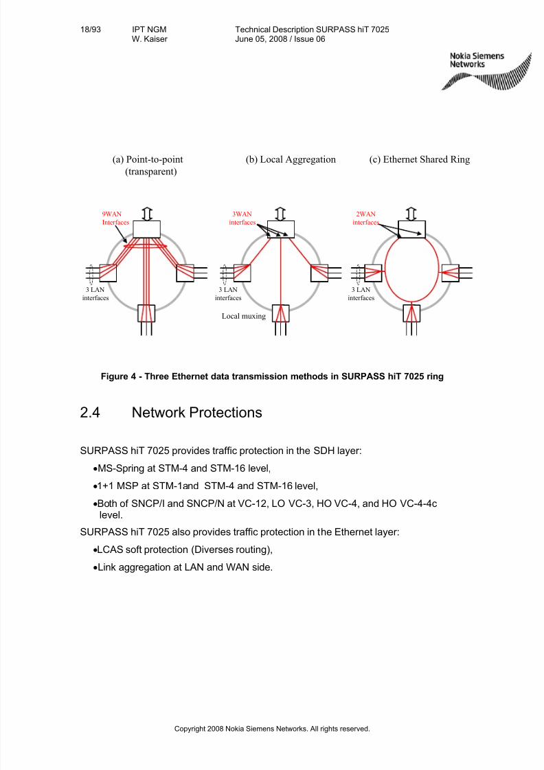
2.3.8 Ethernet Transport Schemes
SURPASS hiT 7025 supports three Ethernet data transport schemes, which aredescribed below:
• Point-to-point transparent
In this mechanism, dedicated bandwidth is assigned to end-to-end traffic. TheVirtual Concatenation technique is used in the SURPASS hiT products to providemore efficient bandwidth assignment. This scheme is more suitable for highsecurity requirements and delay-sensitive traffic as each traffic has a dedicatedbandwidth. The drawback is the limited bandwidth efficiency. As we know,Ethernet traffic has bursty characteristics and is delay insensitive. Statisticalmultiplexing is usually employed in data network to achieve bandwidth efficiency.Dedicated bandwidth per data flow is not efficient for bursty traffic transmission.
• Layer 2 aggregation
In this mechanism, the Ethernet switching and aggregation is performed at the NEto allow local user traffic to be aggregated into a higher rate SDH trunk. Thestatistical multiplexing of multiple Ethernet traffic makes the bandwidth utilizationmore efficient.
• Ethernet Shared Ring (ESR)
The ESR (Ethernet Shared Ring) is a variable length packet switched multi-node
ring.•Data traffic shares the same ring bandwidth
•Nodes on ring have IEEE802.3 Address
•Header has IEEE802.3 type Destination Address and Source Address
•MAC and VLAN based switching
•Destination strips unicast packets
•Drop and continue for broadcast and multicast
•Source node strips broadcast packets
•Class of Service indication in the header supports multiple traffic priorities on ring
•Rapid Spanning Tree protocol (IEEE 802.1w and IEEE802.1s) to prevent buildingloops and to provide layer 2 protections in ring configuration.
The ESR (Ethernet Shared Ring) technology can efficiently add/drop or duplicatethe data traffic on a ring. This dramatically increases the transport efficiency whencompared with the traditional point-to-point networking technology that may lead toback-haul traffic and inefficient multicast traffic.
ESR is based on the RSTP technology to prevent the Ethernet Loop andBroadcast Storm. If using the Multi-STP, functionality of the spatial reuse, differentVLAN can go through different path, and can balance the traffic between the
different paths.
7/27/2019 Surpass Hit 7025 Td
http://slidepdf.com/reader/full/surpass-hit-7025-td 18/93
18/93 IPT NGMW. Kaiser
Technical Description SURPASS hiT 7025June 05, 2008 / Issue 06
Copyright 2008 Nokia Siemens Networks. All rights reserved.
(c) Ethernet Shared Ring(a) Point-to-point
(transparent)
(b) Local Aggregation
3WAN
interfaces
9WAN
Interfaces
3 LAN
interfaces
2WAN
interfaces
3 LAN
interfaces
3 LAN
interfaces
Local muxing
Figure 4 - Three Ethernet data transmission methods in SURPASS hiT 7025 ring
2.4 Network Protections
SURPASS hiT 7025 provides traffic protection in the SDH layer:
•MS-Spring at STM-4 and STM-16 level,
• 1+1 MSP at STM-1and STM-4 and STM-16 level,
•Both of SNCP/I and SNCP/N at VC-12, LO VC-3, HO VC-4, and HO VC-4-4clevel.
SURPASS hiT 7025 also provides traffic protection in the Ethernet layer:
• LCAS soft protection (Diverses routing),
• Link aggregation at LAN and WAN side.
7/27/2019 Surpass Hit 7025 Td
http://slidepdf.com/reader/full/surpass-hit-7025-td 19/93
19/93 IPT NGMW. Kaiser
Technical Description SURPASS hiT 7025June 05, 2008 / Issue 06
Copyright 2008 Nokia Siemens Networks. All rights reserved.
2.5 Main Features & Strengths
2.5.1 Flexibility
SURPASS hiT 7025 offers the flexibility to be used as full blown ADM-1/ ADM-4 tocompact ADM-16.
Interconnection to your SDH network can be at STM-16, STM-4 or STM-1 level.
For reach of very long and ultra long distance applications without use of intermediatedregenerators optical booster and preamplifiers are offered. Maximum distances up to160 km (in compliance with ITU-T Recommendation G.692 U-16.2/3) can be achieved.
2.5.2 Reliability
SURPASS hiT 7025 is due to its full redundancy concept a very reliable product:
The system is based on the standardized SDH technology, which is a market provennetworking technology.
Highly integrated components guarantee for highest system reliability:
Optical transmission can be protected using Multiplex Section Shared Protection Ring,Sub-Network Connection Protection (SNCP), and Multiplex Section Protection 1+1
unidirectional / bidirectional.
Thermal Sensor detects if the internal temperature exceeds the threshold and raise theover temperature alarm.
2.5.3 Modularity and Scalability
SURPASS hiT 7025 is of modular design and allows therefore a high configurationversatility.
All optical line interfaces uses SFP optical modules. This modularity reduces thesparepart stock and increases the flexibility of the system as on the same card differenttypes of SFP modules can be used on different ports (e.g. short haul and long haul).
The scalability from full blow ADM-1/ ADM-4 to compact ADM-16 allows for flexiblegrowth with evolving networking needs.
SURPASS hiT 7025 offers the ability to interface with all SIEMENS and other vendor’soptical networking systems.
The same applies for data processing equipment as the equipment offers standardizedEthernet interfaces (10/100 BaseT or Gigabit Ethernet).
2.5.4 Ease of use
All optical and electrical interfaces have front access.
7/27/2019 Surpass Hit 7025 Td
http://slidepdf.com/reader/full/surpass-hit-7025-td 20/93
20/93 IPT NGMW. Kaiser
Technical Description SURPASS hiT 7025June 05, 2008 / Issue 06
Copyright 2008 Nokia Siemens Networks. All rights reserved.
Support for Small Form-factor Pluggable (SFP) optical interfaces for STM-16, STM-4,
STM-1, and GE SFP optical interfaces, allow convenient field replacement of theoptical interfaces. As the network evolves, different optical modules can be inserted tomeet the changing network environment and growth.
Additional, state-of-art electrical SFP module is supported for STM-1 interface card andGE card.
2.5.5 Data Handling Capabilities
Support for 4094 VLANs per L2 switch card in order to transport end-user data
securely with a variety of Class-of-Service options that allow differentiated servicesbetween users or between applications with a given user.
Ethernet traffic is encapsulated into SDH using either GFP. This provides the mostadvanced and efficient way to carry data traffic within a SDH network.
Virtual Concatenation is used to provide scalable, efficient, compatible, and resilientuse of SDH to move traffic. This greatly increases the useable bandwidth of thenetwork.
7/27/2019 Surpass Hit 7025 Td
http://slidepdf.com/reader/full/surpass-hit-7025-td 21/93
21/93 IPT NGMW. Kaiser
Technical Description SURPASS hiT 7025June 05, 2008 / Issue 06
Copyright 2008 Nokia Siemens Networks. All rights reserved.
3. System Application
SURPASS hiT 7025 multi-service access platform is a highly flexible product capableof supporting a variety of network applications like bandwidth access, service-on-demand and LAN services.
SURPASS hiT 7025 can be configured in such a way that it supports a large variety of network applications with any mix of PDH, SDH and Ethernet services.
3.1 Networking Capability
SURPASS hiT 7025 provides high flexibility and compactness supporting a largevariety of configurations for STM-16, STM-4 and STM-1 network applications:
• Termination and multiplexing
•Small local cross connect
• Linear
•Ring
•Multi Ring closure
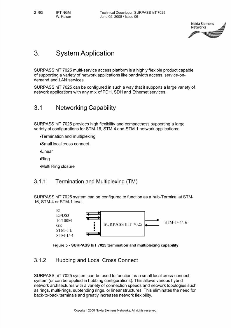
3.1.1 Termination and Multiplexing (TM)
SURPASS hiT 7025 system can be configured to function as a hub-Terminal at STM-16, STM-4 or STM-1 level.
Figure 5 - SURPASS hiT 7025 termination and multiplexing capability
3.1.2 Hubbing and Local Cross Connect
SURPASS hiT 7025 system can be used to function as a small local cross-connectsystem (or can be applied in hubbing configurations). This allows various hybrid
network architectures with a variety of connection speeds and network topologies suchas rings, multi-rings, subtending rings, or linear structures. This eliminates the need for back-to-back terminals and greatly increases network flexibility.
SURPASS hiT 7025STM-1/-4/16
E1
E3/DS3
10/100M
GE
STM -1 ESTM-1/-4
7/27/2019 Surpass Hit 7025 Td
http://slidepdf.com/reader/full/surpass-hit-7025-td 22/93
22/93 IPT NGMW. Kaiser
Technical Description SURPASS hiT 7025June 05, 2008 / Issue 06
Copyright 2008 Nokia Siemens Networks. All rights reserved.
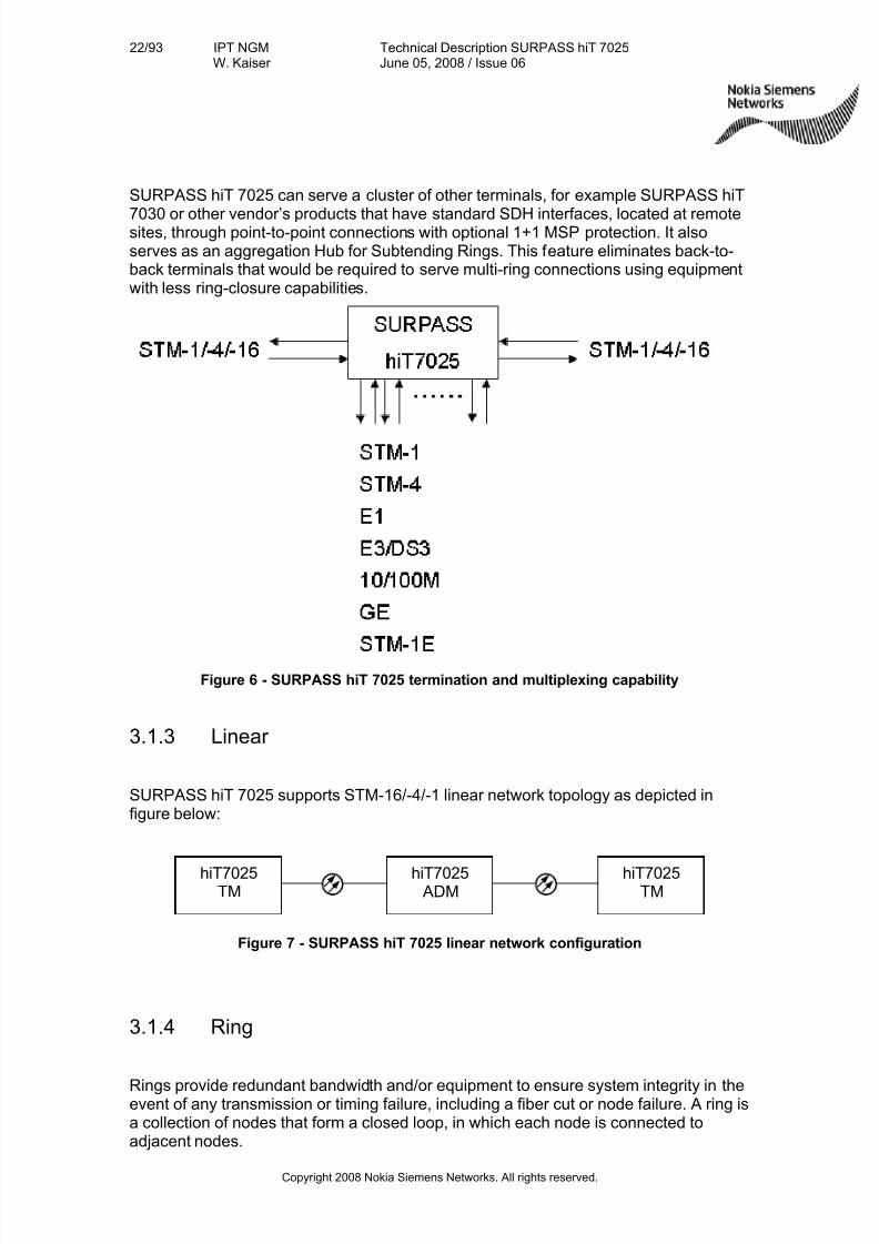
SURPASS hiT 7025 can serve a cluster of other terminals, for example SURPASS hiT
7030 or other vendor’s products that have standard SDH interfaces, located at remotesites, through point-to-point connections with optional 1+1 MSP protection. It alsoserves as an aggregation Hub for Subtending Rings. This feature eliminates back-to-back terminals that would be required to serve multi-ring connections using equipmentwith less ring-closure capabilities.
Figure 6 - SURPASS hiT 7025 termination and multiplexing capability
3.1.3 Linear
SURPASS hiT 7025 supports STM-16/-4/-1 linear network topology as depicted infigure below:
Figure 7 - SURPASS hiT 7025 linear network configuration
3.1.4 Ring
Rings provide redundant bandwidth and/or equipment to ensure system integrity in theevent of any transmission or timing failure, including a fiber cut or node failure. A ring isa collection of nodes that form a closed loop, in which each node is connected toadjacent nodes.
hiT7025TM
hiT7025 ADM
hiT7025TM
7/27/2019 Surpass Hit 7025 Td
http://slidepdf.com/reader/full/surpass-hit-7025-td 23/93
23/93 IPT NGMW. Kaiser
Technical Description SURPASS hiT 7025June 05, 2008 / Issue 06
Copyright 2008 Nokia Siemens Networks. All rights reserved.
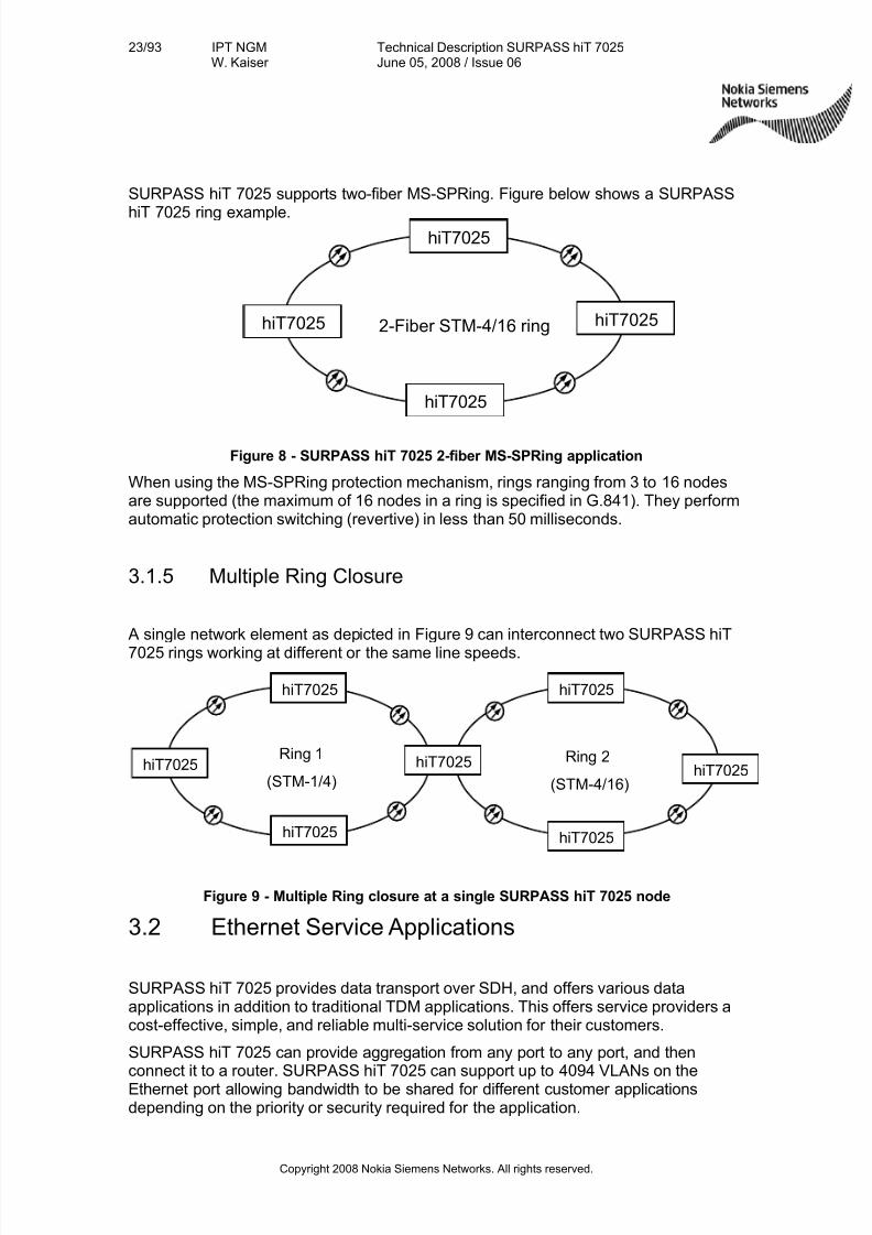
SURPASS hiT 7025 supports two-fiber MS-SPRing. Figure below shows a SURPASS
hiT 7025 ring example.
Figure 8 - SURPASS hiT 7025 2-fiber MS-SPRing application
When using the MS-SPRing protection mechanism, rings ranging from 3 to 16 nodesare supported (the maximum of 16 nodes in a ring is specified in G.841). They performautomatic protection switching (revertive) in less than 50 milliseconds.
3.1.5 Multiple Ring Closure
A single network element as depicted in 378HFigure 9 can interconnect two SURPASS hiT
7025 rings working at different or the same line speeds.
Figure 9 - Multiple Ring closure at a single SURPASS hiT 7025 node
3.2 Ethernet Service Applications
SURPASS hiT 7025 provides data transport over SDH, and offers various dataapplications in addition to traditional TDM applications. This offers service providers acost-effective, simple, and reliable multi-service solution for their customers.
SURPASS hiT 7025 can provide aggregation from any port to any port, and thenconnect it to a router. SURPASS hiT 7025 can support up to 4094 VLANs on theEthernet port allowing bandwidth to be shared for different customer applicationsdepending on the priority or security required for the application.
2-Fiber STM-4/16 ring
hiT7025
hiT7025 hiT7025
hiT7025
Ring 1
(STM-1/4)
hiT7025
hiT7025 hiT7025
hiT7025
hiT7025
hiT7025
hiT7025Ring 2
(STM-4/16)
7/27/2019 Surpass Hit 7025 Td
http://slidepdf.com/reader/full/surpass-hit-7025-td 24/93
24/93 IPT NGMW. Kaiser
Technical Description SURPASS hiT 7025June 05, 2008 / Issue 06
Copyright 2008 Nokia Siemens Networks. All rights reserved.
Normally a user does not require all of the available bandwidth, for instance 600 Mbit/s
which can be provided by a VC-4-4v. By using the VLAN capability, the wholebandwidth of 600 Mbit/s can be allocated across multiple users, giving each acommitted information input rate. Hence, the bandwidth of the physical link can bemore effectively utilized.
In addition, using Virtual Concatenation and LCAS can more accurately adjust thephysical bandwidth to meet customer demands, as opposed to traditional contiguousconcatenation. This further enhances bandwidth efficiency.
Additionally to being able to provide precise customer-required bandwidth levels, four queues for service priority can be assigned per Port/VLAN. This enables additionalflexibility in pricing and over-subscription service plans.
By using the VLAN function, the operator can provide Transparent VLAN Service(TVS) for different customers. For example, a GE user or multiple 10/100M Ethernetusers can be aggregated and transported while retaining secure connections.
The use of GFP data mapping techniques within SURPASS hiT 7025 greatly improvesthe bandwidth efficiency of the connections.
7/27/2019 Surpass Hit 7025 Td
http://slidepdf.com/reader/full/surpass-hit-7025-td 25/93
25/93 IPT NGMW. Kaiser
Technical Description SURPASS hiT 7025June 05, 2008 / Issue 06
Copyright 2008 Nokia Siemens Networks. All rights reserved.
4. System Description
4.1 Physical Structure and Module Construction
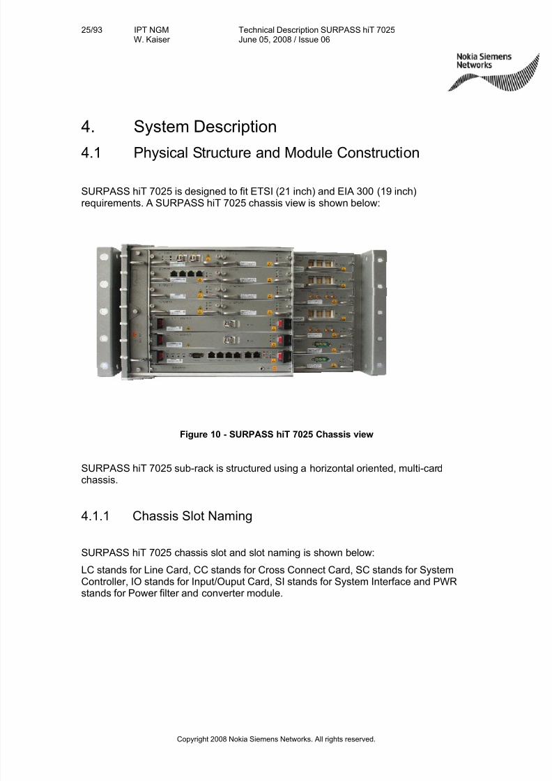
SURPASS hiT 7025 is designed to fit ETSI (21 inch) and EIA 300 (19 inch)requirements. A SURPASS hiT 7025 chassis view is shown below:
Figure 10 - SURPASS hiT 7025 Chassis view
SURPASS hiT 7025 sub-rack is structured using a horizontal oriented, multi-cardchassis.
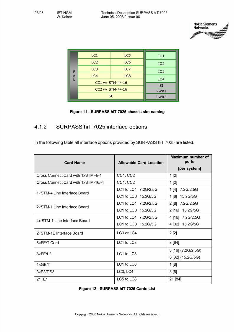
4.1.1 Chassis Slot Naming
SURPASS hiT 7025 chassis slot and slot naming is shown below:
LC stands for Line Card, CC stands for Cross Connect Card, SC stands for SystemController, IO stands for Input/Ouput Card, SI stands for System Interface and PWRstands for Power filter and converter module.
7/27/2019 Surpass Hit 7025 Td
http://slidepdf.com/reader/full/surpass-hit-7025-td 26/93
26/93 IPT NGMW. Kaiser
Technical Description SURPASS hiT 7025June 05, 2008 / Issue 06
Copyright 2008 Nokia Siemens Networks. All rights reserved.
Figure 11 - SURPASS hiT 7025 chassis slot naming
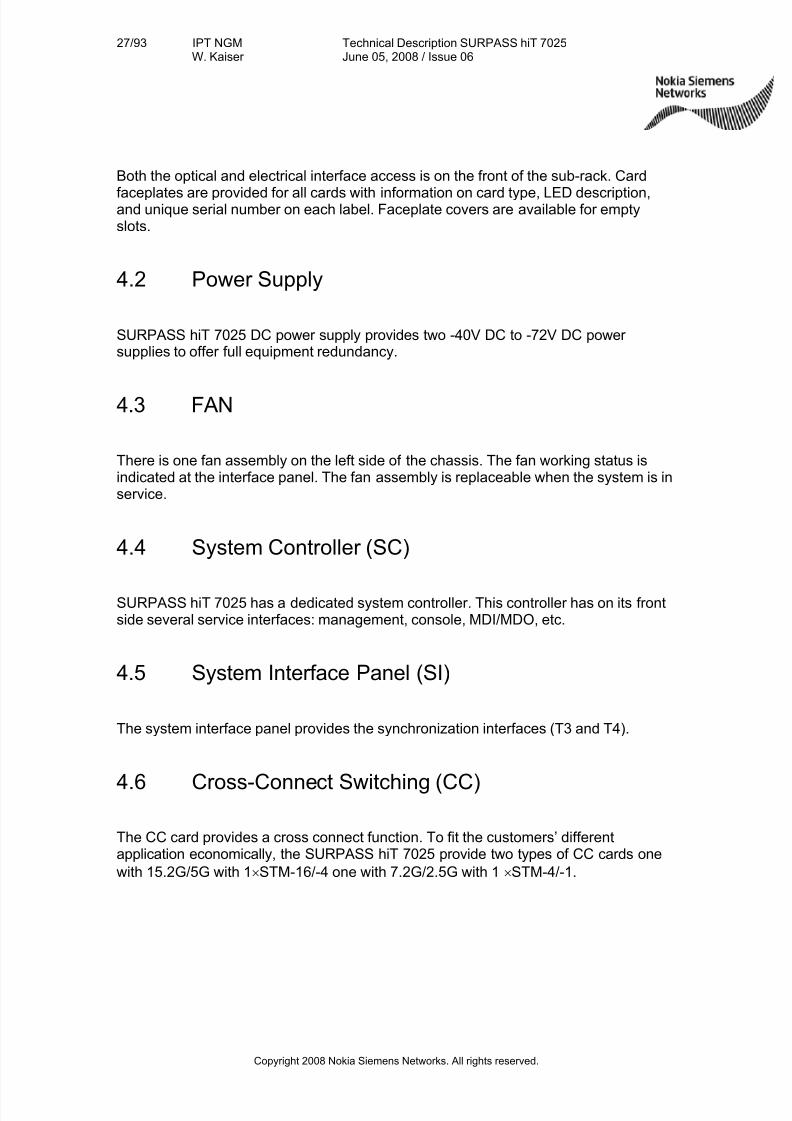
4.1.2 SURPASS hiT 7025 interface options
In the following table all interface options provided by SURPASS hiT 7025 are listed.
Card Name Allowable Card Location
Maximum number of ports
[per system]
Cross Connect Card with 1xSTM-4/-1 CC1, CC2 1 [2]
Cross Connect Card with 1xSTM-16/-4 CC1, CC2 1 [2]
1× STM-4 Line Interface BoardLC1 to LC4 7.2G/2.5G
LC1 to LC8 15.2G/5G
1 [4] 7.2G/2.5G
1 [8] 15.2G/5G
2× STM-1 Line Interface BoardLC1 to LC4 7.2G/2.5G
LC1 to LC8 15.2G/5G
2 [8] 7.2G/2.5G
2 [16] 15.2G/5G
4x STM-1 Line Interface BoardLC1 to LC4 7.2G/2.5G
LC1 to LC8 15.2G/5G
4 [16] 7.2G/2.5G
4 [32] 15.2G/5G
2× STM-1E Interface Board LC3 or LC4 2 [2]
8× FE/T Card LC1 to LC8 8 [64]
8× FE/L2 LC1 to LC88 [16] (7.2G/2.5G)
8 [32] (15.2G/5G)
1× GE/T LC1 to LC8 1 [8]
3× E3/DS3 LC3, LC4 3 [6]
21× E1 LC5 to LC8 21 [84]
Figure 12 - SURPASS hiT 7025 Cards List
CC2 w/ STM-4/-16
F
A
NCC1 w/ STM-4/-16
LC7
SC
LC3
IO4
IO1
IO2
IO3
SI
PWR1
PWR2
LC5LC1
LC6LC2
LC8LC4
CC2 w/ STM-4/-16
F
A
NCC1 w/ STM-4/-16
LC7
SC
LC3
IO4
IO1
IO2
IO3
SI
PWR1
PWR2
LC5LC1
LC6LC2
LC8LC4
7/27/2019 Surpass Hit 7025 Td
http://slidepdf.com/reader/full/surpass-hit-7025-td 27/93
27/93 IPT NGMW. Kaiser
Technical Description SURPASS hiT 7025June 05, 2008 / Issue 06
Copyright 2008 Nokia Siemens Networks. All rights reserved.
Both the optical and electrical interface access is on the front of the sub-rack. Card
faceplates are provided for all cards with information on card type, LED description,and unique serial number on each label. Faceplate covers are available for emptyslots.
4.2 Power Supply
SURPASS hiT 7025 DC power supply provides two -40V DC to -72V DC power supplies to offer full equipment redundancy.
4.3 FAN
There is one fan assembly on the left side of the chassis. The fan working status isindicated at the interface panel. The fan assembly is replaceable when the system is inservice.
4.4 System Controller (SC)
SURPASS hiT 7025 has a dedicated system controller. This controller has on its frontside several service interfaces: management, console, MDI/MDO, etc.
4.5 System Interface Panel (SI)
The system interface panel provides the synchronization interfaces (T3 and T4).
4.6 Cross-Connect Switching (CC)
The CC card provides a cross connect function. To fit the customers’ differentapplication economically, the SURPASS hiT 7025 provide two types of CC cards one
with 15.2G/5G with 1× STM-16/-4 one with 7.2G/2.5G with 1× STM-4/-1.
7/27/2019 Surpass Hit 7025 Td
http://slidepdf.com/reader/full/surpass-hit-7025-td 28/93
28/93 IPT NGMW. Kaiser
Technical Description SURPASS hiT 7025June 05, 2008 / Issue 06
Copyright 2008 Nokia Siemens Networks. All rights reserved.
4.7 SDH Interfaces
SURPASS hiT 7025 provides following SDH interfaces:
• 1× STM-4 Interface Board
• 2× STM-1 Interface Board
• 4x STM-1 Interface Board
• 2× STM-1E interface Card
4.7.1 1x STM-4 Interface Board
This board provides 1 optical interface with a signal rate of 622 Mbits/s. The STM-4interface is fully compliant with ITU-T G.707 and G.957 standards. This modulesupports hot swappable SFP optical module. The STM-4 optical interface on this boardcan be paired with any STM-4 interface on another board for 2-fiber STM-4 ringclosure. The STM-4 ring supports MS-SPRING, MSP, and SNCP protection function.
4.7.2 2× STM-1 Interface Board
This board provides 2 optical interfaces with a signal rate of 155 Mbits/s. The STM-1interfaces are fully compliant with ITU-T G.707 and G.957 standards. This boardsupports two hot swappable SFP optical modules or SFP electrical modules. On STM-1 level MSP and SNCP protection is supported.
4.7.3 4× STM-1 Interface Board
This board provides 4 optical interfaces with a signal rate of 155 Mbits/s. The STM-1
interfaces are fully compliant with ITU-T G.707 and G.957 standards. This boardsupports four hot swappable SFP optical modules or SFP electrical modules. On STM-1 level MSP and SNCP protection is supported.
4.7.4 2× STM-1E (W/P) Interface
This card offers 2× STM-1E electrical interface, and supports redundant (1+1) 2× STM-1E card protection.
Using the redundancy option implement the following devices two 2× STM-1E
functional cards and one 2× STM-1E I/O board.
7/27/2019 Surpass Hit 7025 Td
http://slidepdf.com/reader/full/surpass-hit-7025-td 29/93
29/93 IPT NGMW. Kaiser
Technical Description SURPASS hiT 7025June 05, 2008 / Issue 06
Copyright 2008 Nokia Siemens Networks. All rights reserved.
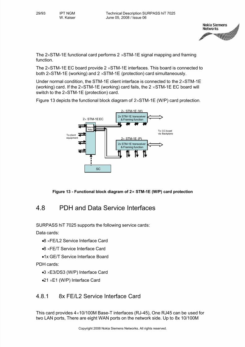
The 2× STM-1E functional card performs 2× STM-1E signal mapping and framing
function.
The 2× STM-1E EC board provide 2× STM-1E interfaces. This board is connected to
both 2× STM-1E (working) and 2× STM-1E (protection) card simultaneously.
Under normal condition, the STM-1E client interface is connected to the 2× STM-1E
(working) card. If the 2× STM-1E (working) card fails, the 2× STM-1E EC board will
switch to the 2× STM-1E (protection) card.
379HFigure 13 depicts the functional block diagram of 2× STM-1E (W/P) card protection.
Figure 13 - Functional block diagram of 2× STM-1E (W/P) card protection
4.8 PDH and Data Service Interfaces
SURPASS hiT 7025 supports the following service cards:
Data cards:
• 8× FE/L2 Service Interface Card
• 8× FE/T Service Interface Card
• 1x GE/T Service Interface Board
PDH cards:
• 3× E3/DS3 (W/P) Interface Card
• 21× E1 (W/P) Interface Card
4.8.1 8x FE/L2 Service Interface Card
This card provides 4×10/100M Base-T interfaces (RJ-45), One RJ45 can be used for two LAN ports, There are eight WAN ports on the network side. Up to 8x 10/100M
2x STM-1E transceiver & Framing function2× STM-1E EC
2× STM-1E (W)
2x STM-1E transceiver & Framing function
SC
Selector Relay
To CC boardvia Backplane
2× STM-1E (P)
To clientequipment
7/27/2019 Surpass Hit 7025 Td
http://slidepdf.com/reader/full/surpass-hit-7025-td 30/93
30/93 IPT NGMW. Kaiser
Technical Description SURPASS hiT 7025June 05, 2008 / Issue 06
Copyright 2008 Nokia Siemens Networks. All rights reserved.
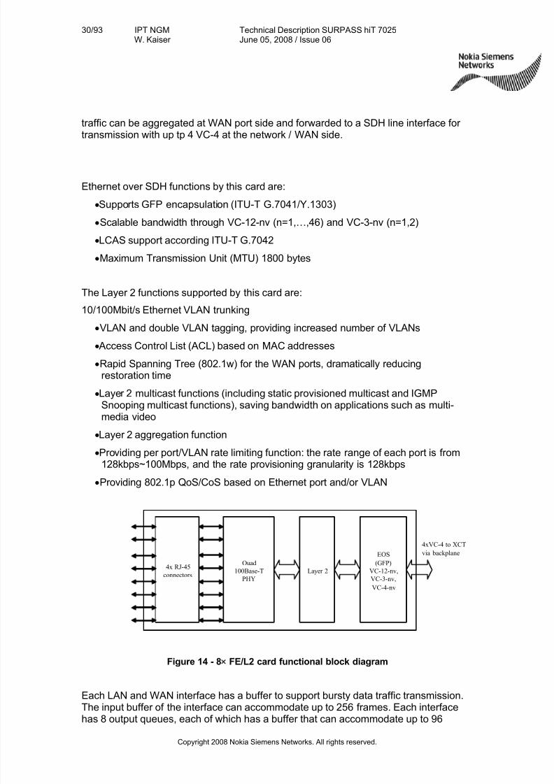
traffic can be aggregated at WAN port side and forwarded to a SDH line interface for
transmission with up tp 4 VC-4 at the network / WAN side.
Ethernet over SDH functions by this card are:
•Supports GFP encapsulation (ITU-T G.7041/Y.1303)
•Scalable bandwidth through VC-12-nv (n=1,…,46) and VC-3-nv (n=1,2)
• LCAS support according ITU-T G.7042
•Maximum Transmission Unit (MTU) 1800 bytes
The Layer 2 functions supported by this card are:
10/100Mbit/s Ethernet VLAN trunking
•VLAN and double VLAN tagging, providing increased number of VLANs
•Access Control List (ACL) based on MAC addresses
•Rapid Spanning Tree (802.1w) for the WAN ports, dramatically reducingrestoration time
• Layer 2 multicast functions (including static provisioned multicast and IGMPSnooping multicast functions), saving bandwidth on applications such as multi-media video
• Layer 2 aggregation function
•Providing per port/VLAN rate limiting function: the rate range of each port is from128kbps~100Mbps, and the rate provisioning granularity is 128kbps
•Providing 802.1p QoS/CoS based on Ethernet port and/or VLAN
Layer 2
Ouad
100Base-T
PHY
EOS
(GFP)
VC-12-nv,
VC-3-nv,
VC-4-nv
4xVC-4 to XCT
via backplane
4x RJ-45
connectors
Figure 14 - 8× FE/L2 card functional block diagram
Each LAN and WAN interface has a buffer to support bursty data traffic transmission.The input buffer of the interface can accommodate up to 256 frames. Each interfacehas 8 output queues, each of which has a buffer that can accommodate up to 96
7/27/2019 Surpass Hit 7025 Td
http://slidepdf.com/reader/full/surpass-hit-7025-td 31/93
31/93 IPT NGMW. Kaiser
Technical Description SURPASS hiT 7025June 05, 2008 / Issue 06
Copyright 2008 Nokia Siemens Networks. All rights reserved.
frames to be sent out. As each input buffer and output buffers are independently using
the dedicated memory spaces, instead of sharing any common memory space, therewill be no mutual influence between the input buffer and the output buffers.
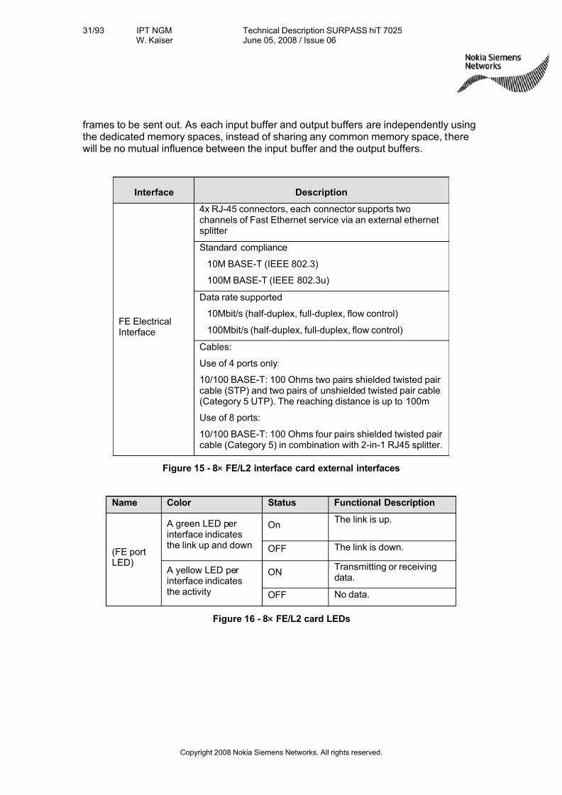
Interface Description
4x RJ-45 connectors, each connector supports twochannels of Fast Ethernet service via an external ethernetsplitter
Standard compliance
10M BASE-T (IEEE 802.3)
100M BASE-T (IEEE 802.3u)
Data rate supported
10Mbit/s (half-duplex, full-duplex, flow control)
100Mbit/s (half-duplex, full-duplex, flow control)FE ElectricalInterface
Cables:
Use of 4 ports only:
10/100 BASE-T: 100 Ohms two pairs shielded twisted pair cable (STP) and two pairs of unshielded twisted pair cable(Category 5 UTP). The reaching distance is up to 100m
Use of 8 ports:
10/100 BASE-T: 100 Ohms four pairs shielded twisted pair cable (Category 5) in combination with 2-in-1 RJ45 splitter.
Figure 15 - 8× FE/L2 interface card external interfaces
Name Color Status Functional Description
OnThe link is up. A green LED per
interface indicatesthe link up and down OFF The link is down.
ONTransmitting or receivingdata.
(FE portLED)
A yellow LED per interface indicatesthe activity OFF No data.
Figure 16 - 8× FE/L2 card LEDs
7/27/2019 Surpass Hit 7025 Td
http://slidepdf.com/reader/full/surpass-hit-7025-td 32/93
32/93 IPT NGMW. Kaiser
Technical Description SURPASS hiT 7025June 05, 2008 / Issue 06
Copyright 2008 Nokia Siemens Networks. All rights reserved.
4.8.2 8x FE/T Service Interface Card
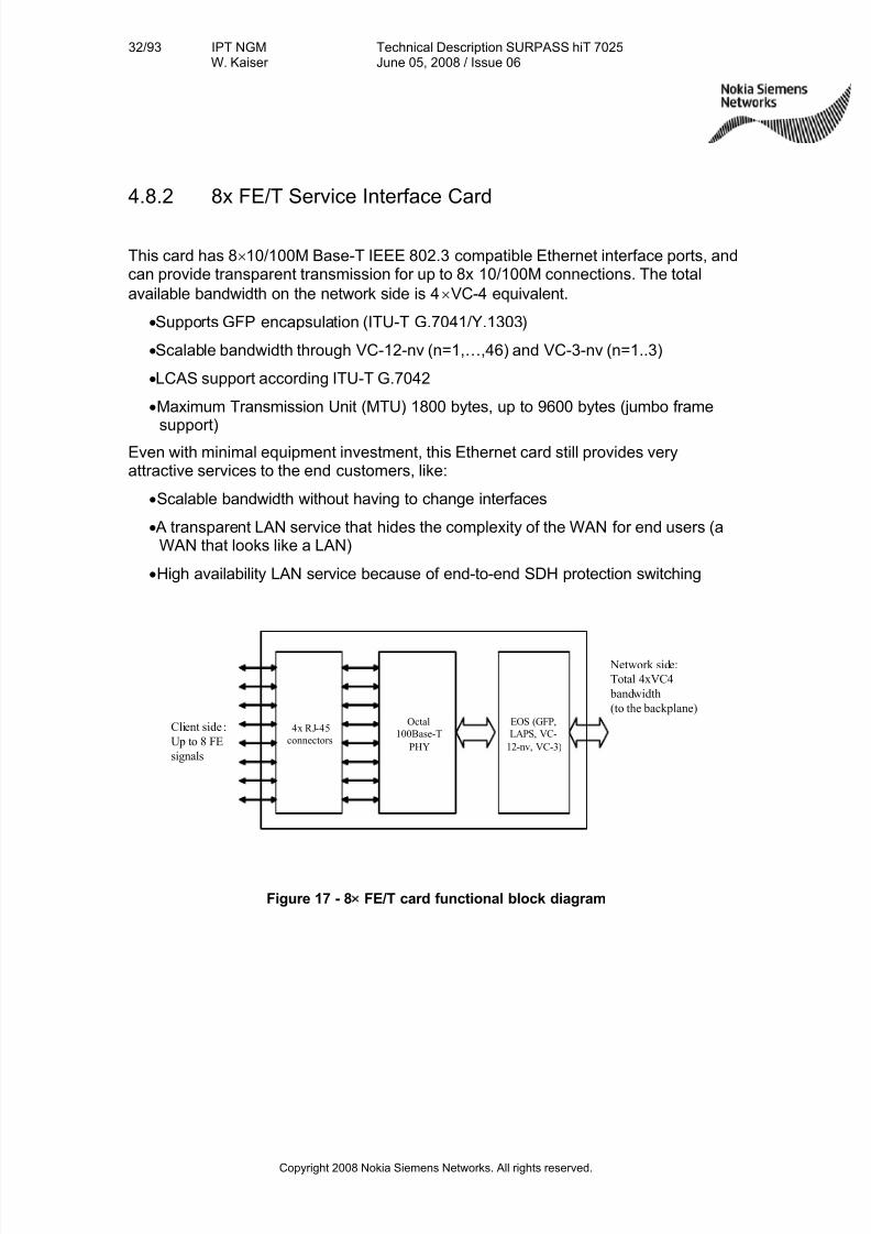
This card has 8× 10/100M Base-T IEEE 802.3 compatible Ethernet interface ports, andcan provide transparent transmission for up to 8x 10/100M connections. The total
available bandwidth on the network side is 4× VC-4 equivalent.
•Supports GFP encapsulation (ITU-T G.7041/Y.1303)
•Scalable bandwidth through VC-12-nv (n=1,…,46) and VC-3-nv (n=1..3)
• LCAS support according ITU-T G.7042
•Maximum Transmission Unit (MTU) 1800 bytes, up to 9600 bytes (jumbo frame
support)Even with minimal equipment investment, this Ethernet card still provides veryattractive services to the end customers, like:
•Scalable bandwidth without having to change interfaces
•A transparent LAN service that hides the complexity of the WAN for end users (aWAN that looks like a LAN)
•High availability LAN service because of end-to-end SDH protection switching
Octal
100Base-T
PHY
EOS (GFP,
LAPS, VC-
12-nv, VC-3)
Network side:
Total 4xVC4
bandwidth
(to the backplane)
4x RJ-45
connectors
Client side :
Up to 8 FE
signals
Figure 17 - 8× FE/T card functional block diagram
7/27/2019 Surpass Hit 7025 Td
http://slidepdf.com/reader/full/surpass-hit-7025-td 33/93
33/93 IPT NGMW. Kaiser
Technical Description SURPASS hiT 7025June 05, 2008 / Issue 06
Copyright 2008 Nokia Siemens Networks. All rights reserved.
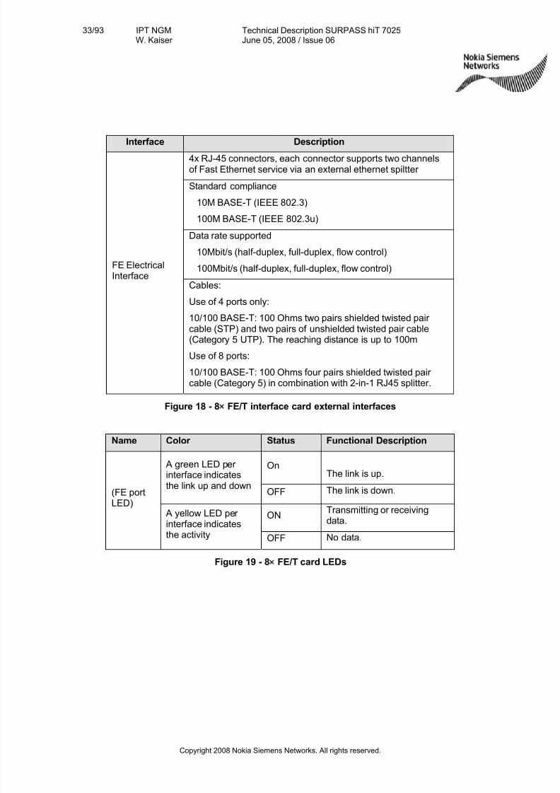
Interface Description
4x RJ-45 connectors, each connector supports two channelsof Fast Ethernet service via an external ethernet spiltter
Standard compliance
10M BASE-T (IEEE 802.3)
100M BASE-T (IEEE 802.3u)
Data rate supported
10Mbit/s (half-duplex, full-duplex, flow control)
100Mbit/s (half-duplex, full-duplex, flow control)FE Electrical
Interface Cables:
Use of 4 ports only:
10/100 BASE-T: 100 Ohms two pairs shielded twisted pair cable (STP) and two pairs of unshielded twisted pair cable(Category 5 UTP). The reaching distance is up to 100m
Use of 8 ports:
10/100 BASE-T: 100 Ohms four pairs shielded twisted pair cable (Category 5) in combination with 2-in-1 RJ45 splitter.
Figure 18 - 8× FE/T interface card external interfaces
Name Color Status Functional Description
OnThe link is up.
A green LED per interface indicatesthe link up and down
OFF The link is down.
ONTransmitting or receivingdata.
(FE portLED)
A yellow LED per interface indicatesthe activity OFF No data.
Figure 19 - 8× FE/T card LEDs
7/27/2019 Surpass Hit 7025 Td
http://slidepdf.com/reader/full/surpass-hit-7025-td 34/93
34/93 IPT NGMW. Kaiser
Technical Description SURPASS hiT 7025June 05, 2008 / Issue 06
Copyright 2008 Nokia Siemens Networks. All rights reserved.
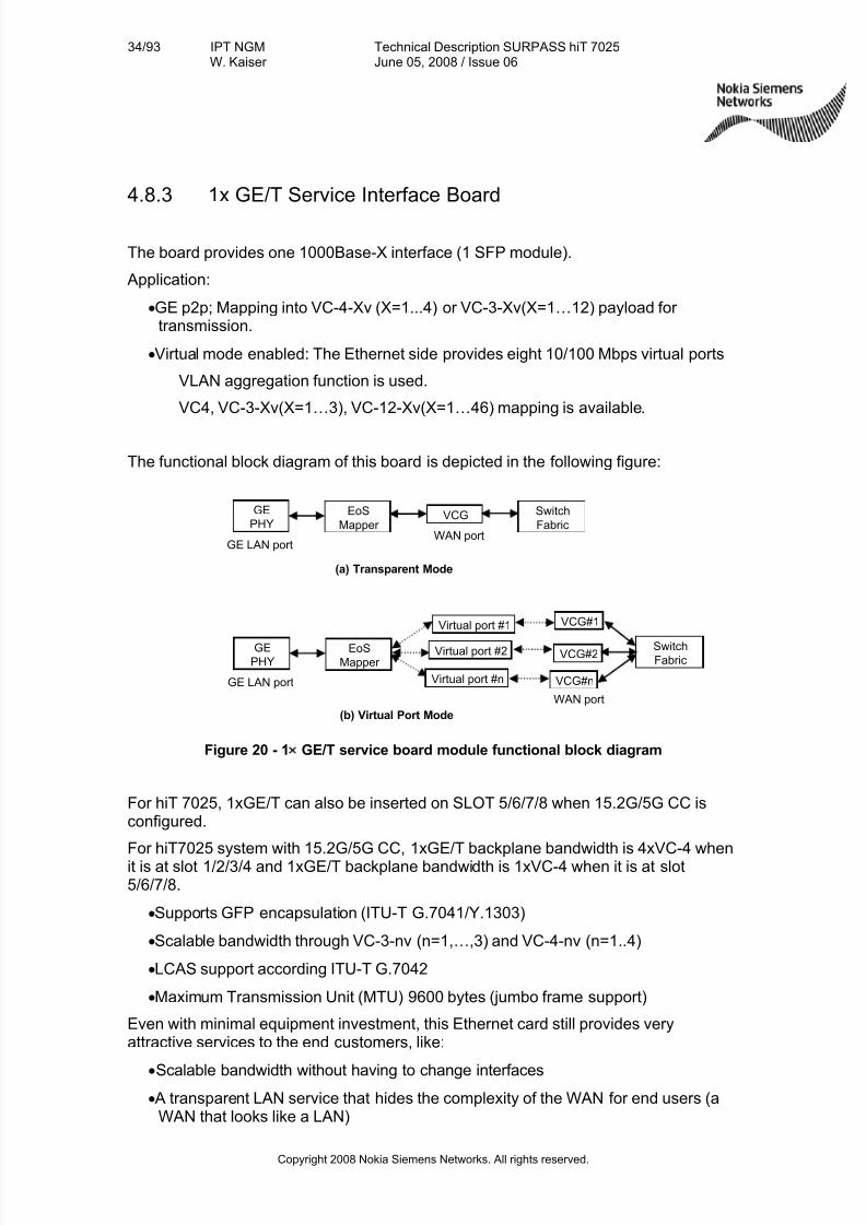
4.8.3 1x GE/T Service Interface Board
The board provides one 1000Base-X interface (1 SFP module).
Application:
•GE p2p; Mapping into VC-4-Xv (X=1...4) or VC-3-Xv(X=1…12) payload for transmission.
•Virtual mode enabled: The Ethernet side provides eight 10/100 Mbps virtual ports
VLAN aggregation function is used.
VC4, VC-3-Xv(X=1…3), VC-12-Xv(X=1…46) mapping is available.
The functional block diagram of this board is depicted in the following figure:
Figure 20 - 1× GE/T service board module functional block diagram
For hiT 7025, 1xGE/T can also be inserted on SLOT 5/6/7/8 when 15.2G/5G CC isconfigured.
For hiT7025 system with 15.2G/5G CC, 1xGE/T backplane bandwidth is 4xVC-4 whenit is at slot 1/2/3/4 and 1xGE/T backplane bandwidth is 1xVC-4 when it is at slot5/6/7/8.
•Supports GFP encapsulation (ITU-T G.7041/Y.1303)
•Scalable bandwidth through VC-3-nv (n=1,…,3) and VC-4-nv (n=1..4)
• LCAS support according ITU-T G.7042
•Maximum Transmission Unit (MTU) 9600 bytes (jumbo frame support)
Even with minimal equipment investment, this Ethernet card still provides veryattractive services to the end customers, like:
•Scalable bandwidth without having to change interfaces•A transparent LAN service that hides the complexity of the WAN for end users (a
WAN that looks like a LAN)
GE
PHY
GE LAN port
VCG#1
VCG#2
Virtual port #1
(a) Transparent Mode
VCG#n
VCG
WAN port
EoS
Mapper
Switch
Fabric
GEPHY
GE LAN port
(b) Virtual Port Mode
WAN port
EoS
Mapper
SwitchFabric
Virtual port #2
Virtual port #n
7/27/2019 Surpass Hit 7025 Td
http://slidepdf.com/reader/full/surpass-hit-7025-td 35/93
35/93 IPT NGMW. Kaiser
Technical Description SURPASS hiT 7025June 05, 2008 / Issue 06
Copyright 2008 Nokia Siemens Networks. All rights reserved.
•High availability LAN service because of end-to-end SDH protection switching
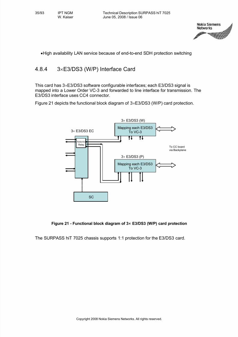
4.8.4 3× E3/DS3 (W/P) Interface Card
This card has 3× E3/DS3 software configurable interfaces; each E3/DS3 signal ismapped into a Lower Order VC-3 and forwarded to line interface for transmission. TheE3/DS3 interface uses CC4 connector.
380HFigure 21 depicts the functional block diagram of 3× E3/DS3 (W/P) card protection.
Figure 21 - Functional block diagram of 3× E3/DS3 (W/P) card protection
The SURPASS hiT 7025 chassis supports 1:1 protection for the E3/DS3 card.
Mapping each E3/DS3
To VC-33× E3/DS3 EC
3× E3/DS3 (W)
Mapping each E3/DS3
To VC-3
SC
Selector
RelayTo CC board
via Backplane
3× E3/DS3 (P)
7/27/2019 Surpass Hit 7025 Td
http://slidepdf.com/reader/full/surpass-hit-7025-td 36/93
36/93 IPT NGMW. Kaiser
Technical Description SURPASS hiT 7025June 05, 2008 / Issue 06
Copyright 2008 Nokia Siemens Networks. All rights reserved.
4.8.5 21× E1 (W/P) Interface Card
The 21× E1 interface card contains the following two types of cards:
(1) 21× E1 Function Card with retiming function
(2) 21× E1 EC (Electrical Connectors) Card with 75Ohm/120Ohm version connector
In the retiming mode, the transmitter eliminates wander and jitter in the incoming clock.
While the rate of the outgoing 2 Mbit/s or 2MHz signal is normally equal to the rate of the 2 Mbit/s or 2MHz signal going into the SDH network, occasionally this relationshipdisappears. A retiming function is necessary for suppression of jitter and wander thatthe 2Mbit/s signal suffers during transmission in SDH and which makes the signaluseless for carrying the synchronous frequency to the PDH domain.
To retime an outgoing 2 Mbit/s or 2MHz signal, means simply to retime this signal withthe internal clock of the multiplexer equipment in which the de-synchronization takesplace. This can be done by reading the recovered 2Mbit/s or 2MHz signal into anelastic store and timing the output of the elastic store with the system clock.
When the device is set in the retiming mode all jitter and wander due to themultiplexing or de-multiplexing process in the transmission is eliminated.
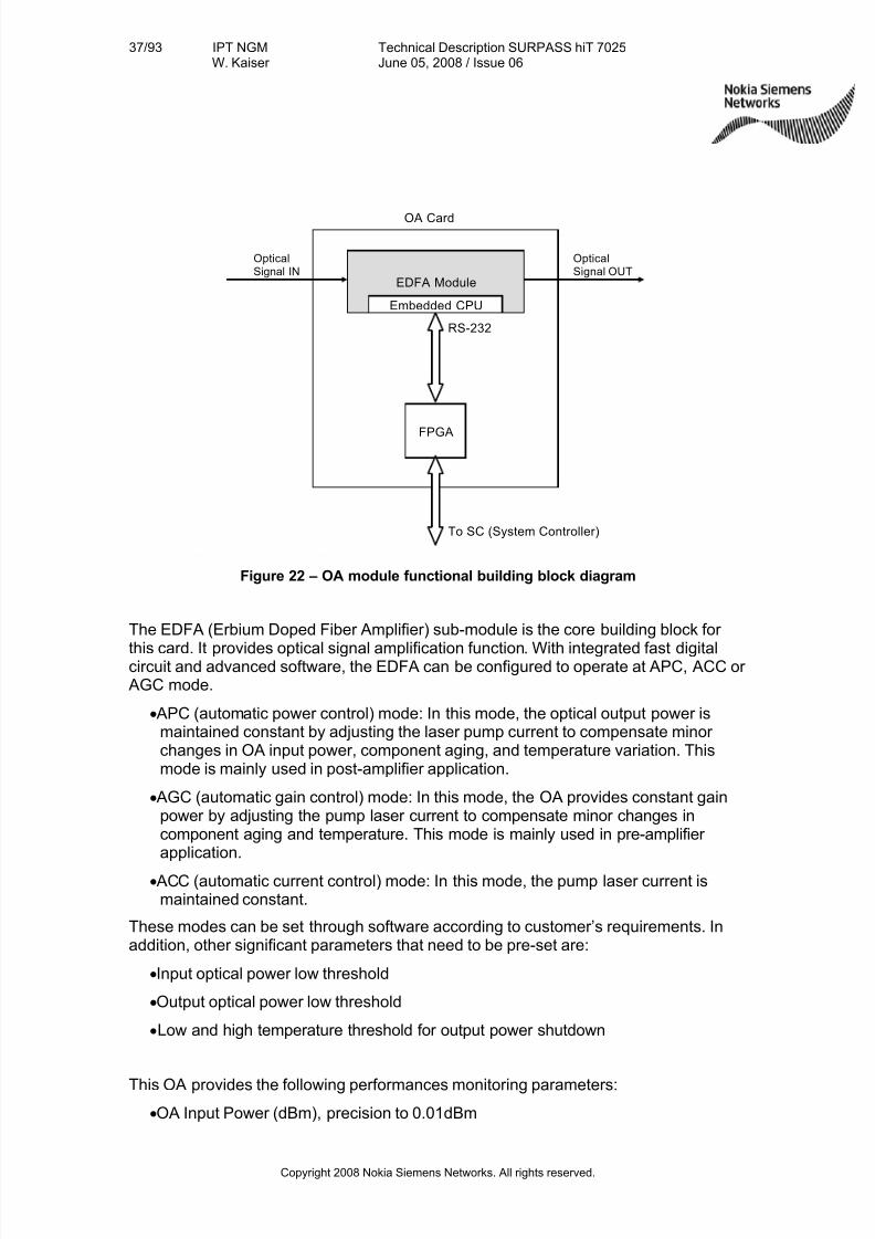
4.9 Optical Amplifier
This OA (Optical Amplifier) module provides uni-directional single optical amplifier function with optical performance monitoring capabilities.
Optical Amplifiers are available with 13, 15 or 18 dBm output power.
Additionally there is also a Pre-amplifier module available (20 dB).
These modules are designed to compensate losses in the entire C band andincreasing therefore the span performance of the system without need for intermediated regenerators. The module functional building block diagram is shownbelow.
7/27/2019 Surpass Hit 7025 Td
http://slidepdf.com/reader/full/surpass-hit-7025-td 37/93
37/93 IPT NGMW. Kaiser
Technical Description SURPASS hiT 7025June 05, 2008 / Issue 06
Copyright 2008 Nokia Siemens Networks. All rights reserved.
EDFA Module
Embedded CPU
RS-232
FPGA
OA Card
OpticalSignal IN
OpticalSignal OUT
To SC (System Controller)
Figure 22 – OA module functional building block diagram
The EDFA (Erbium Doped Fiber Amplifier) sub-module is the core building block for
this card. It provides optical signal amplification function. With integrated fast digitalcircuit and advanced software, the EDFA can be configured to operate at APC, ACC or AGC mode.
•APC (automatic power control) mode: In this mode, the optical output power ismaintained constant by adjusting the laser pump current to compensate minor changes in OA input power, component aging, and temperature variation. Thismode is mainly used in post-amplifier application.
•AGC (automatic gain control) mode: In this mode, the OA provides constant gainpower by adjusting the pump laser current to compensate minor changes incomponent aging and temperature. This mode is mainly used in pre-amplifier application.
•ACC (automatic current control) mode: In this mode, the pump laser current ismaintained constant.
These modes can be set through software according to customer’s requirements. Inaddition, other significant parameters that need to be pre-set are:
• Input optical power low threshold
•Output optical power low threshold
• Low and high temperature threshold for output power shutdown
This OA provides the following performances monitoring parameters:
•OA Input Power (dBm), precision to 0.01dBm
7/27/2019 Surpass Hit 7025 Td
http://slidepdf.com/reader/full/surpass-hit-7025-td 38/93
38/93 IPT NGMW. Kaiser
Technical Description SURPASS hiT 7025June 05, 2008 / Issue 06
Copyright 2008 Nokia Siemens Networks. All rights reserved.
•OA Output Power (dBm), precision to 0.01dBm
•OA Module Gain (dB), precision to 0.01dB
•OA Pump Power (mW), precision to 0.01mW
•OA module internal temperature, precision to 0.1 C degree
•OA module pump drive current, precision to 0.1 A
•OA power module power supply voltage, precision to 0.01V
This OA module board can be configured to use one of the following 4 EDFA sub-modules:
•Booster 13dBm
•Booster 15dBm
•Booster 18dBm
•Pre-amp 20dB
All EDFA sub-modules above use single-stage or dual-stage un-cooled 980nm pumplasers.
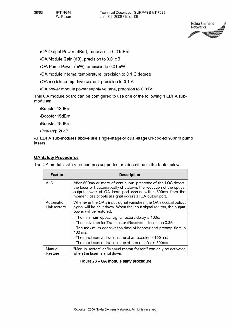
OA Safety Procedures
The OA module safety procedures supported are described in the table below.
Feature Description
ALS After 500ms or more of continuous presence of the LOS defect,the laser will automatically shutdown; the reduction of the opticaloutput power at OA input port occurs within 800ms from themoment loss of optical signal occurs at OA output port.
Whenever the OA’s input signal vanishes, the OA’s optical outputsignal will be shut down. When the input signal returns, the outputpower will be restored.
AutomaticLink restore
- The minimum optical signal restore delay is 100s.
- The activation for Transmitter /Receiver is less than 0.85s.
- The maximum deactivation time of booster and preamplifiers is100 ms.
- The maximum activation time of an booster is 100 ms.
- The maximum activation time of preamplifier is 300ms.
ManualRestore
"Manual restart" or "Manual restart for test" can only be activatedwhen the laser is shut down.
Figure 23 – OA module safty procedure
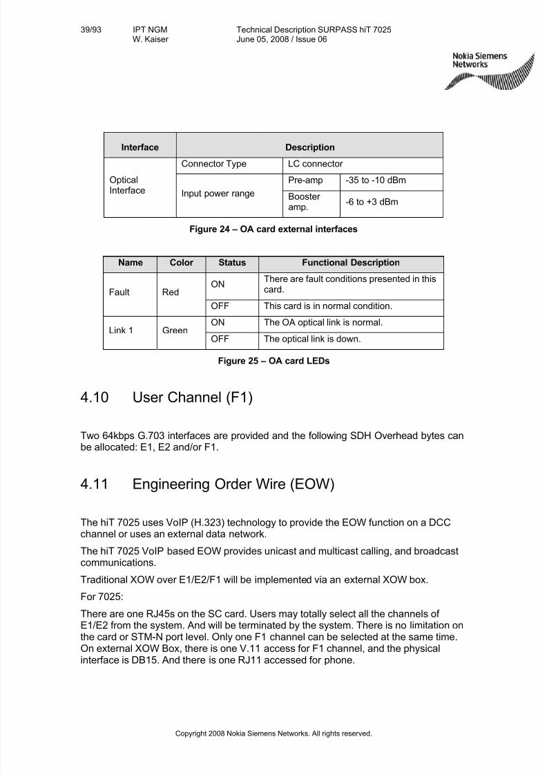
7/27/2019 Surpass Hit 7025 Td
http://slidepdf.com/reader/full/surpass-hit-7025-td 39/93
39/93 IPT NGMW. Kaiser
Technical Description SURPASS hiT 7025June 05, 2008 / Issue 06
Copyright 2008 Nokia Siemens Networks. All rights reserved.
Interface Description
Connector Type LC connector
Pre-amp -35 to -10 dBmOpticalInterface Input power range Booster
amp.-6 to +3 dBm
Figure 24 – OA card external interfaces
Name Color Status Functional Description
ONThere are fault conditions presented in thiscard.Fault Red
OFF This card is in normal condition.
ON The OA optical link is normal.Link 1 Green
OFF The optical link is down.
Figure 25 – OA card LEDs
4.10 User Channel (F1)
Two 64kbps G.703 interfaces are provided and the following SDH Overhead bytes canbe allocated: E1, E2 and/or F1.
4.11 Engineering Order Wire (EOW)
The hiT 7025 uses VoIP (H.323) technology to provide the EOW function on a DCCchannel or uses an external data network.
The hiT 7025 VoIP based EOW provides unicast and multicast calling, and broadcastcommunications.
Traditional XOW over E1/E2/F1 will be implemented via an external XOW box.
For 7025:
There are one RJ45s on the SC card. Users may totally select all the channels of E1/E2 from the system. And will be terminated by the system. There is no limitation onthe card or STM-N port level. Only one F1 channel can be selected at the same time.On external XOW Box, there is one V.11 access for F1 channel, and the physicalinterface is DB15. And there is one RJ11 accessed for phone.
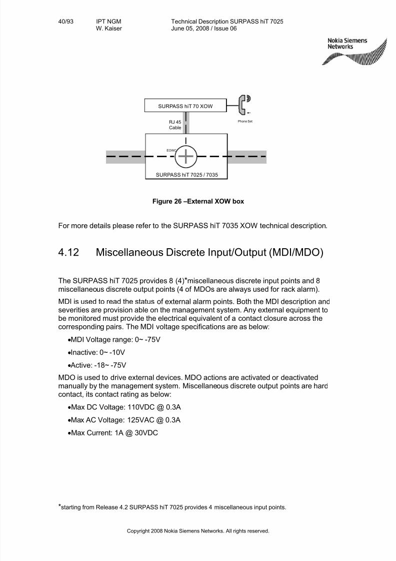
7/27/2019 Surpass Hit 7025 Td
http://slidepdf.com/reader/full/surpass-hit-7025-td 40/93
40/93 IPT NGMW. Kaiser
Technical Description SURPASS hiT 7025June 05, 2008 / Issue 06
Copyright 2008 Nokia Siemens Networks. All rights reserved.
SURPASS hiT 7025 / 7035
SURPASS hiT 70 XOW
RJ 45
Cable
EOWC
Phone Set
Figure 26 –External XOW box
For more details please refer to the SURPASS hiT 7035 XOW technical description.
4.12 Miscellaneous Discrete Input/Output (MDI/MDO)
The SURPASS hiT 7025 provides 8 (4)* miscellaneous discrete input points and 8miscellaneous discrete output points (4 of MDOs are always used for rack alarm).
MDI is used to read the status of external alarm points. Both the MDI description andseverities are provision able on the management system. Any external equipment tobe monitored must provide the electrical equivalent of a contact closure across thecorresponding pairs. The MDI voltage specifications are as below:
•MDI Voltage range: 0~ -75V
• Inactive: 0~ -10V
•Active: -18~ -75V
MDO is used to drive external devices. MDO actions are activated or deactivatedmanually by the management system. Miscellaneous discrete output points are hard
contact, its contact rating as below:
•Max DC Voltage: 110VDC @ 0.3A
•Max AC Voltage: 125VAC @ 0.3A
•Max Current: 1A @ 30VDC
* starting from Release 4.2 SURPASS hiT 7025 provides 4 miscellaneous input points.
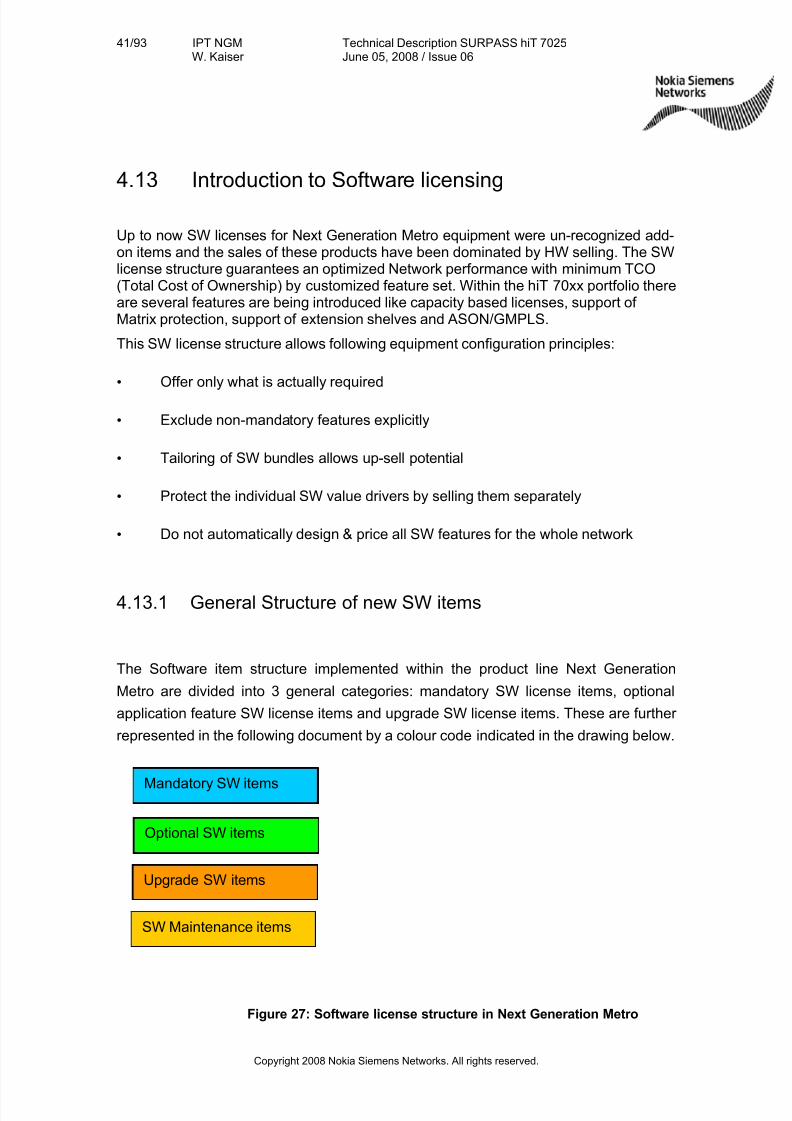
7/27/2019 Surpass Hit 7025 Td
http://slidepdf.com/reader/full/surpass-hit-7025-td 41/93
41/93 IPT NGMW. Kaiser
Technical Description SURPASS hiT 7025June 05, 2008 / Issue 06
Copyright 2008 Nokia Siemens Networks. All rights reserved.
Mandatory SW items
Optional SW items
Upgrade SW items
SW Maintenance items
4.13 Introduction to Software licensing
Up to now SW licenses for Next Generation Metro equipment were un-recognized add-on items and the sales of these products have been dominated by HW selling. The SWlicense structure guarantees an optimized Network performance with minimum TCO(Total Cost of Ownership) by customized feature set. Within the hiT 70xx portfolio thereare several features are being introduced like capacity based licenses, support of Matrix protection, support of extension shelves and ASON/GMPLS.
This SW license structure allows following equipment configuration principles:
• Offer only what is actually required
• Exclude non-mandatory features explicitly
• Tailoring of SW bundles allows up-sell potential
• Protect the individual SW value drivers by selling them separately
• Do not automatically design & price all SW features for the whole network
4.13.1 General Structure of new SW items
The Software item structure implemented within the product line Next Generation
Metro are divided into 3 general categories: mandatory SW license items, optional
application feature SW license items and upgrade SW license items. These are further
represented in the following document by a colour code indicated in the drawing below.
Figure 27: Software license structure in Next Generation Metro
7/27/2019 Surpass Hit 7025 Td
http://slidepdf.com/reader/full/surpass-hit-7025-td 42/93
42/93 IPT NGMW. Kaiser
Technical Description SURPASS hiT 7025June 05, 2008 / Issue 06
Copyright 2008 Nokia Siemens Networks. All rights reserved.
Mandatory SW i tems
The mandatory Sof tware i tems represent the basic functionality of the system, and
one of these core licenses are mandatory to be equipped for each equipment core.
Opt ional SW i tems
The opt ional Sof tware i tems are items that represent additional types of functionality.
These can be:
• Additional optional feature packages
• Additional functionality related with HW configuration
• Additional capacity
Upgrade SW i tems
The upg rade Sof tware items are available for each individual product to provide
release upgrades. Release upgrades are in general upgrades where the succeeding
release contains a higher feature set. This is in general represented by a number in the
release name of the product.
SW Maintenace i tems
The Software Maintenance i tems are available for each individual product to provide
maintenance related services, namely to solve technical queries (to provide qualified
answers and assistance for any general technical/operational queries), for trouble
resolution (to handle customer reported suspected defects and o deliver workarounds
and/or final solutions) and to provide software updates (to ensure a regular, proactive,
delivery of software update packages with respective release documentation).
4.13.2 Software license structure of SURPASS hiT 7025
SURPASS hiT 7025 is a versatile network element having the equipping option as ADM for STM-1/-4 (equipped with a small switch matrix) or as ADM for STM-4/-16
(equipped with a large switch matrix).Therefore there are two different mandatory core licenses, an ADM-1/4 core licenseand a ADM-4/-16 license.
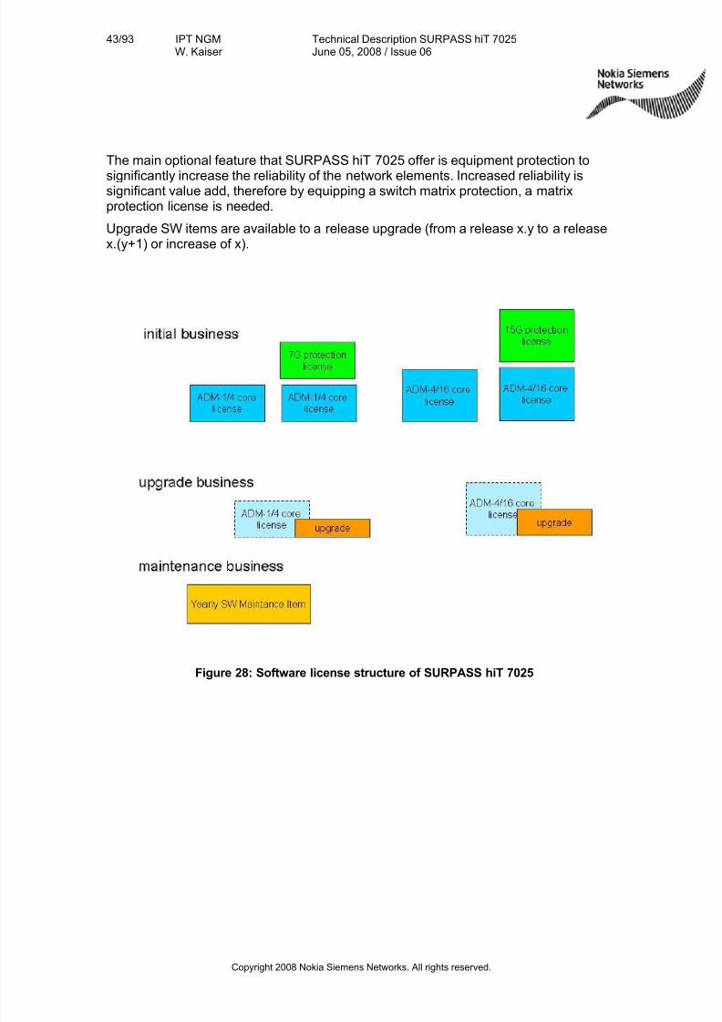
7/27/2019 Surpass Hit 7025 Td
http://slidepdf.com/reader/full/surpass-hit-7025-td 43/93
43/93 IPT NGMW. Kaiser
Technical Description SURPASS hiT 7025June 05, 2008 / Issue 06
Copyright 2008 Nokia Siemens Networks. All rights reserved.
The main optional feature that SURPASS hiT 7025 offer is equipment protection to
significantly increase the reliability of the network elements. Increased reliability issignificant value add, therefore by equipping a switch matrix protection, a matrixprotection license is needed.
Upgrade SW items are available to a release upgrade (from a release x.y to a releasex.(y+1) or increase of x).
Figure 28: Software license structure of SURPASS hiT 7025
7/27/2019 Surpass Hit 7025 Td
http://slidepdf.com/reader/full/surpass-hit-7025-td 44/93
44/93 IPT NGMW. Kaiser
Technical Description SURPASS hiT 7025June 05, 2008 / Issue 06
Copyright 2008 Nokia Siemens Networks. All rights reserved.
5. Protection and Redundancy
5.1 Network Protection
SURPASS hiT 7025 supports multiple layer network protection functions and multiplelayer protection escalation. The network protection functions supported are:
•MS-SPRing, in compliance with ITU-T G.841
•MSP 1+1 protection, revertive or non-revertive modes, in compliance with ITU-TG.841
•
SNCP at VC-12, VC-3, VC-4, VC-4-4c level in compliance with ITU-T G.841•Rapid Spanning Tree Protocol (RSTP) to provide Layer 2 Ethernet data protection
by converging data to another path, in compliance with IEEE 802.1w protocol
5.1.1 MS-SPRing
SURPASS hiT 7025 supports 2 fibers MS-SPRing at STM-16/-4 level. The protection(detection and switching) is guaranteed to be finished within 50ms. The wait-to-restoretime is user configurable with a default value of 5 minutes. The system also supports
force switching and manual switching.For example, In an STM-4 ring with the MS-SPRing function enabled, a total of 4 AU4sare divided evenly into 2 groups, working AU4s (time slots 1 and 2) and protection AU4s (time slots 3 and 4).
The SURPASS hiT 7025 MS-Spring implementation supports also low priority traffic bysupporting NUT feature (Non-preempt-able Unprotected Traffic).
5.1.2 MSP
1+1 MSP (G.841/Clause 7) protects an STM-N link between two adjacent SDH MS(multiplexing section) elements.
SURPASS hiT 7025 supports 1+1 multiplex section protection (MSP) on all STM-Noptical ports. The MSP 1+1 can be either uni-direction or bi-direction. The protectiontime is less than 50ms.
SURPASS hiT 7025 also supports Manual Switch and Forced Switch of MSP, revertiveand non-revertive MSP.
7/27/2019 Surpass Hit 7025 Td
http://slidepdf.com/reader/full/surpass-hit-7025-td 45/93
45/93 IPT NGMW. Kaiser
Technical Description SURPASS hiT 7025June 05, 2008 / Issue 06
Copyright 2008 Nokia Siemens Networks. All rights reserved.
5.1.3 SNCP
SURPASS hiT 7025 supports Sub-Network Connection (SNC) protection (ITU-TG.841). It is available at VC-12, VC-3, VC-4 and VC-4-4c level. SURPASS hiT 7025supports VC-4/-3/-12 SNC protection between any pair of VC-4/-3/-12s in any STM-Ncards and also supports VC-4-4c SNC protection in STM-4 cards and STM-16 ports.
The protection switch time for SNC protection is less than 50 ms.
The SNC protection scheme supported in SURPASS hiT 7025 is an inherentlymonitored SNCP (SNCP/I) or non-intrusively monitored SNCP (SNCP/N). The SNCPprotected VC-4s are protected against AIS or LOP at the AU-4 level (server layer defects) and against misconnections (trace identifier mismatch or VC-4 dTIM),
disconnections (unequipped signal or VC-4 dUNEQ), or signal degradations (VC-4dDEG) in the VC-4 itself. Likewise, SNCP protected VC-3s and VC-12s are protectedagainst TU3/12-AIS, TU3/12-LOP (server layer defects), VC-3/12 dTIM, dUNEQ, anddDEG. Also SNCP protected VC-4-4cs are protected against AU-4-4c-LOP/AIS, MS- AIS, LOF, LOS, VC-4-4c- dTIM, dUNEQ and dDEG.
The SURPASS hiT 7025 SNCP implementation supports also non-revertive, single-ended and drop & continues features.
An advantage of SNCP is the flexibility to select any segment of the path for protection.The SNC protection can be applied to an end-to-end (from source to sink terminationpoint) VC-n path, or to one or multiple links within the end-to-end path. It is also simpleand easy to implement, as there is no signaling required between the source anddestination nodes.
5.1.4 LCAS
SURPASS hiT 7025 supports the combination of VCAT and LCAS to provide VC-4,VC-3 or VC-12 level protection. LCAS allows hitless adjustment of the size of a virtuallyconcatenated group of channels.
For example, whenVC-4-nv bandwidth is used to transmit data traffic through thenetwork. In the case that certain VC-4s in the same VC-4-nv group fail, SURPASS hiT7025 will use LCAS to delete the failed VCs from the group, and the traffic isdynamically, or on the fly adapted to the rest VC-4s bandwidth for transmission.Without LCAS, partial bandwidth failure will result in the failure of the end-to-end traffictransmission.
When the failure is repaired, the LCAS will automatically add (recover) the deleted VC-4s to the VC group.
7/27/2019 Surpass Hit 7025 Td
http://slidepdf.com/reader/full/surpass-hit-7025-td 46/93
46/93 IPT NGMW. Kaiser
Technical Description SURPASS hiT 7025June 05, 2008 / Issue 06
Copyright 2008 Nokia Siemens Networks. All rights reserved.
5.1.5 Ethernet Shared Protection Ring
SURPASS hiT 7025 supports L2 switching and RSTP (IEEE 802.1w compliant) basedL2 protection in ESR. The convergence time can reach less than two seconds. RSTPbased protection is different from SDH layer protection. SDH protection is considered aphysical layer protection, while RSTP is a Layer 2 protection. When layer 2 Ethernetdata fault is detected, even though the physical connectivity is good, RSTP will makethe convergence of the data to another physical path.
5.1.6 Multiple Layers Protection
SURPASS hiT 7025 supports network protection functions in multiple layers. Theselayers are SDH and Ethernet data. In order to coordinate the protection activitiesbetween layers, SURPASS hiT 7025 provides a protection escalation mechanism. Thisuses different hold off times at different layers to make sure that lower layer protectionoccurs first. For example, in a fiber failure condition, SDH protection will be performedfirst. If SDH layer protection is successful, no Ethernet layer protection occurs(because it is not needed). However, if the SDH protection fails after a certain period of time (the hold off time for Ethernet layer protection), Ethernet layer protection willoccur. That is, the higher the layer, the longer the hold off time will be. In this way, thesystem can fully take the advantage of the fast SDH protection (<50ms), and have
multi-layer protections for higher system reliability.For Ethernet services, if the layer protection fails (the failure is declared after a pre-defined hold off time; for example 100ms), the RSTP in the Ethernet layer will react tothe failure and provide the protection by converging the data to an alternative path. Inthe ESR, the alternative path is the path on the other side of the ring. The hold off timein the Ethernet layer is user provision able.
5.2 Equipment Redundancy and Protection
5.2.1 Redundant Power Supply
SURPASS hiT 7025 provides optional 1+1 DC power supply protection. The DC power voltage is -40 to -72 V. Both power modules are active and coupled via an “OR”function to share the load current.
SURPASS hiT 7025 permits convenient field replacement of either power modulewithout affecting traffic.
5.2.2 Redundant Cross-Connect
SURPASS hiT 7025 provides optional redundant cross-connect and timing card.
7/27/2019 Surpass Hit 7025 Td
http://slidepdf.com/reader/full/surpass-hit-7025-td 47/93
47/93 IPT NGMW. Kaiser
Technical Description SURPASS hiT 7025June 05, 2008 / Issue 06
Copyright 2008 Nokia Siemens Networks. All rights reserved.
5.2.3 Electrical Interface Module Protection
SURPASS hiT 7025 provides the following electrical interface card protection:
(1) 1:3 21× E1 card protection (revertive)
(2) 1:1 3× E3/DS3 (W/P) card protection (non-revertive)
(3) 1+1 2× STM-1E (W/P) card protection (non-revertive)
5.2.4 Protection under Abnormal Condition
Software download protection: when power fails during software download,SURPASS hiT 7025 BIOS will be written protected. The BIOS is guaranteed not tostart the uncompleted software program or data file. After the power recovery,SURPASS hiT 7025 supports continued software downloading. All application softwareand data files can be downloaded to the NE while the NE is still in-service. Thesoftware download verification process prevents data errors from transmission.
Software upgrade protection: SURPASS hiT 7025 controller contains two copies of the system software. During the software upgrade, one copy will be replaced by thenew version of the software. After the new version is confirmed, the switch over to thenew version does not affect the service traffic, and the existing system setting andconfiguration are maintained. If the system upgrade fails, the system can be switchedback to the old version. Only when the new software version is confirmed workingproperly, can the old version be erased.
5.2.5 Software Fault Tolerance
The software design of SURPASS hiT 7025 NE adopts the principle of softwareengineering, involving a top-down and object-oriented software design methods.
Advanced software developing management and designing technology assure the highquality and reliability of NE software.
SURPASS hiT 7025 provides multiple protections for software programs and data withself-checking and self-recovering functions.
Data transmission checking and re-transmitting mechanism are implemented in allcontrol signal transmission channels between modules to minimize the transmittingerrors.
Adopted internal watchdog-circuit in CPU to avoid the impact of software deadlock or shut down. No service is affected when the software performs warm reset.
Adopted common software platform approach: SURPASS hiT 7025 supports code-
sharing and re-using as many as field proven codes to provide higher softwarereliability.
7/27/2019 Surpass Hit 7025 Td
http://slidepdf.com/reader/full/surpass-hit-7025-td 48/93
48/93 IPT NGMW. Kaiser
Technical Description SURPASS hiT 7025June 05, 2008 / Issue 06
Copyright 2008 Nokia Siemens Networks. All rights reserved.
5.2.6 Data Security
SURPASS hiT 7025 adopts database module technology and manages data uniformly,which enhances the data security:
Database and database files each have a data checking function.
Database files are protected according to importance level of data. Errors of lower leveldatabase files will not affect higher level database files.
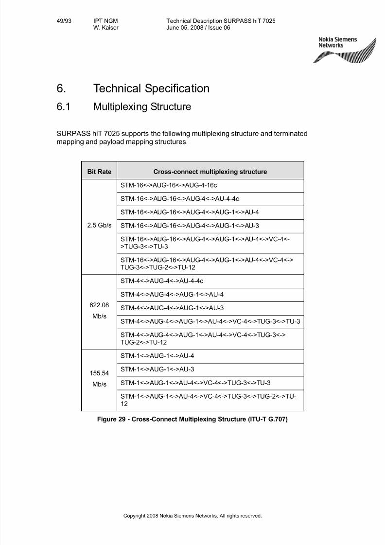
7/27/2019 Surpass Hit 7025 Td
http://slidepdf.com/reader/full/surpass-hit-7025-td 49/93
49/93 IPT NGMW. Kaiser
Technical Description SURPASS hiT 7025June 05, 2008 / Issue 06
Copyright 2008 Nokia Siemens Networks. All rights reserved.
6. Technical Specification
6.1 Multiplexing Structure
SURPASS hiT 7025 supports the following multiplexing structure and terminatedmapping and payload mapping structures.
Bit Rate Cross-connect multiplexing structure
STM-16<->AUG-16<->AUG-4-16c
STM-16<->AUG-16<->AUG-4<->AU-4-4c
STM-16<->AUG-16<->AUG-4<->AUG-1<->AU-4
STM-16<->AUG-16<->AUG-4<->AUG-1<->AU-3
STM-16<->AUG-16<->AUG-4<->AUG-1<->AU-4<->VC-4<->TUG-3<->TU-3
2.5 Gb/s
STM-16<->AUG-16<->AUG-4<->AUG-1<->AU-4<->VC-4<->TUG-3<->TUG-2<->TU-12
STM-4<->AUG-4<->AU-4-4c
STM-4<->AUG-4<->AUG-1<->AU-4
STM-4<->AUG-4<->AUG-1<->AU-3
STM-4<->AUG-4<->AUG-1<->AU-4<->VC-4<->TUG-3<->TU-3
622.08
Mb/s
STM-4<->AUG-4<->AUG-1<->AU-4<->VC-4<->TUG-3<->TUG-2<->TU-12
STM-1<->AUG-1<->AU-4
STM-1<->AUG-1<->AU-3
STM-1<->AUG-1<->AU-4<->VC-4<->TUG-3<->TU-3
155.54
Mb/s
STM-1<->AUG-1<->AU-4<->VC-4<->TUG-3<->TUG-2<->TU-12
Figure 29 - Cross-Connect Multiplexing Structure (ITU-T G.707)
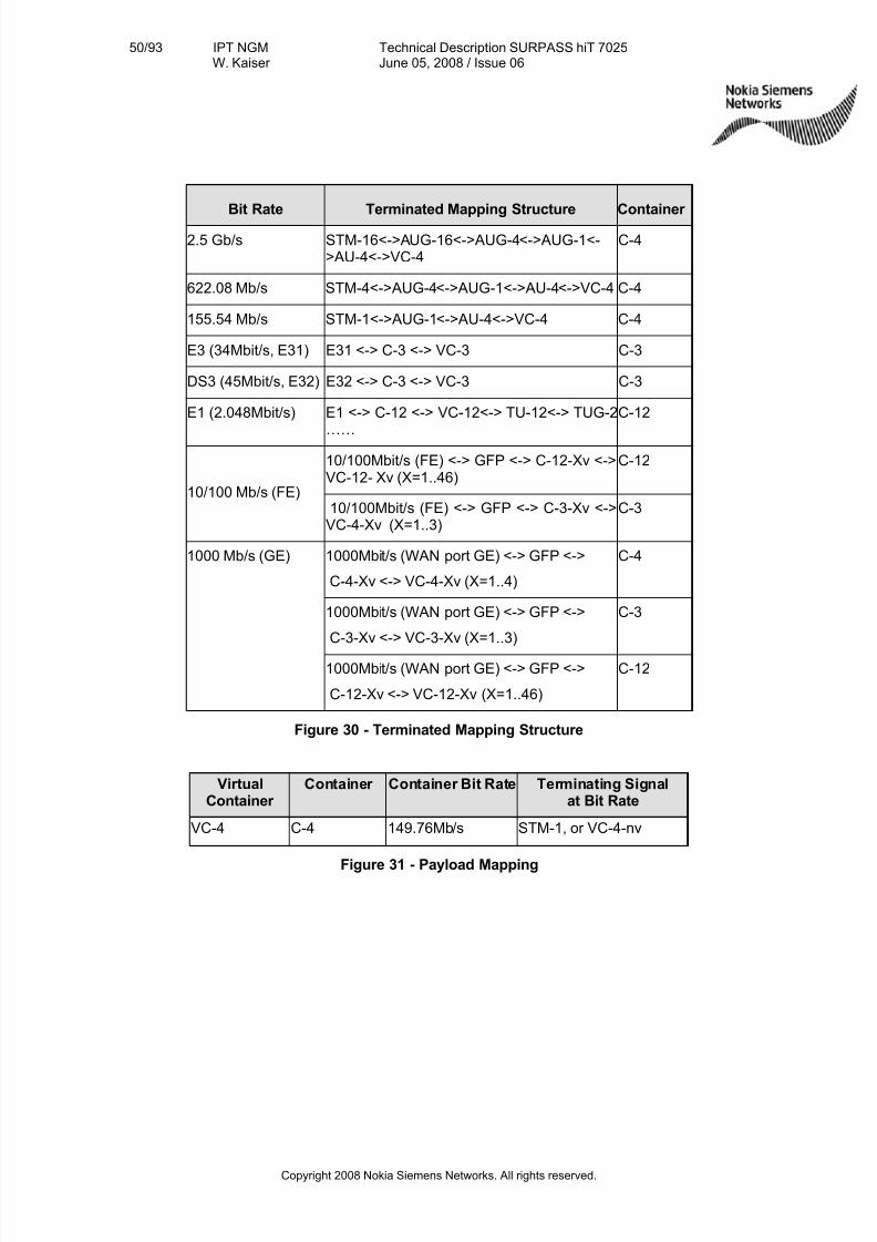
7/27/2019 Surpass Hit 7025 Td
http://slidepdf.com/reader/full/surpass-hit-7025-td 50/93
50/93 IPT NGMW. Kaiser
Technical Description SURPASS hiT 7025June 05, 2008 / Issue 06
Copyright 2008 Nokia Siemens Networks. All rights reserved.
Bit Rate Terminated Mapping Structure Container
2.5 Gb/s STM-16<->AUG-16<->AUG-4<->AUG-1<->AU-4<->VC-4
C-4
622.08 Mb/s STM-4<->AUG-4<->AUG-1<->AU-4<->VC-4 C-4
155.54 Mb/s STM-1<->AUG-1<->AU-4<->VC-4 C-4
E3 (34Mbit/s, E31) E31 <-> C-3 <-> VC-3 C-3
DS3 (45Mbit/s, E32) E32 <-> C-3 <-> VC-3 C-3
E1 (2.048Mbit/s) E1 <-> C-12 <-> VC-12<-> TU-12<-> TUG-2
……
C-12
10/100Mbit/s (FE) <-> GFP <-> C-12-Xv <->VC-12- Xv (X=1..46)
C-12
10/100 Mb/s (FE)10/100Mbit/s (FE) <-> GFP <-> C-3-Xv <->VC-4-Xv (X=1..3)
C-3
1000Mbit/s (WAN port GE) <-> GFP <->
C-4-Xv <-> VC-4-Xv (X=1..4)
C-4
1000Mbit/s (WAN port GE) <-> GFP <->
C-3-Xv <-> VC-3-Xv (X=1..3)
C-3
1000 Mb/s (GE)
1000Mbit/s (WAN port GE) <-> GFP <->
C-12-Xv <-> VC-12-Xv (X=1..46)
C-12
Figure 30 - Terminated Mapping Structure
VirtualContainer
Container Container Bit Rate Terminating Signalat Bit Rate
VC-4 C-4 149.76Mb/s STM-1, or VC-4-nv
Figure 31 - Payload Mapping
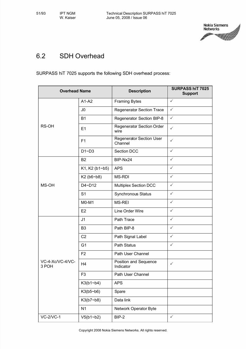
7/27/2019 Surpass Hit 7025 Td
http://slidepdf.com/reader/full/surpass-hit-7025-td 51/93
51/93 IPT NGMW. Kaiser
Technical Description SURPASS hiT 7025June 05, 2008 / Issue 06
Copyright 2008 Nokia Siemens Networks. All rights reserved.
6.2 SDH Overhead
SURPASS hiT 7025 supports the following SDH overhead process:
Overhead Name DescriptionSURPASS hiT 7025
Support
A1-A2 Framing Bytes 3
J0 Regenerator Section Trace 3
B1 Regenerator Section BIP-8 3
E1Regenerator Section Order wire
3
F1Regenerator Section User Channel
3
RS-OH
D1~D3 Section DCC 3
B2 BIP-Nx24 3
K1, K2 (b1~b5) APS 3
K2 (b6~b8) MS-RDI 3
D4~D12 Multiplex Section DCC 3
S1 Synchronous Status 3
M0-M1 MS-REI 3
MS-OH
E2 Line Order Wire 3
J1 Path Trace 3
B3 Path BIP-8 3
C2 Path Signal Label 3
G1 Path Status 3
F2 Path User Channel
H4Position and SequenceIndicator
3
F3 Path User Channel
K3(b1~b4) APS
K3(b5~b6) Spare
K3(b7~b8) Data link
VC-4-Xc/VC-4/VC-3 POH
N1 Network Operator Byte
VC-2/VC-1 V5(b1~b2) BIP-2 3
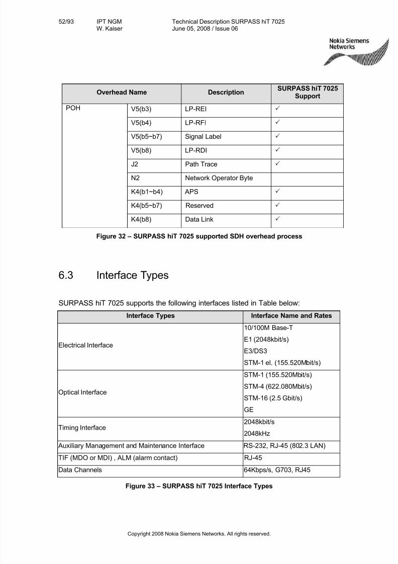
7/27/2019 Surpass Hit 7025 Td
http://slidepdf.com/reader/full/surpass-hit-7025-td 52/93
52/93 IPT NGMW. Kaiser
Technical Description SURPASS hiT 7025June 05, 2008 / Issue 06
Copyright 2008 Nokia Siemens Networks. All rights reserved.
Overhead Name DescriptionSURPASS hiT 7025
SupportV5(b3) LP-REI 3
V5(b4) LP-RFI 3
V5(b5~b7) Signal Label 3
V5(b8) LP-RDI 3
J2 Path Trace 3
N2 Network Operator Byte
K4(b1~b4) APS 3
K4(b5~b7) Reserved 3
POH
K4(b8) Data Link 3
Figure 32 – SURPASS hiT 7025 supported SDH overhead process
6.3 Interface Types
SURPASS hiT 7025 supports the following interfaces listed in Table below:
Interface Types Interface Name and Rates
Electrical Interface
10/100M Base-T
E1 (2048kbit/s)
E3/DS3
STM-1 el. (155.520Mbit/s)
Optical Interface
STM-1 (155.520Mbit/s)
STM-4 (622.080Mbit/s)
STM-16 (2.5 Gbit/s)
GE
Timing Interface2048kbit/s
2048kHz
Auxiliary Management and Maintenance Interface RS-232, RJ-45 (802.3 LAN)
TIF (MDO or MDI) , ALM (alarm contact) RJ-45
Data Channels 64Kbps/s, G703, RJ45
Figure 33 – SURPASS hiT 7025 Interface Types
7/27/2019 Surpass Hit 7025 Td
http://slidepdf.com/reader/full/surpass-hit-7025-td 53/93
53/93 IPT NGMW. Kaiser
Technical Description SURPASS hiT 7025June 05, 2008 / Issue 06
Copyright 2008 Nokia Siemens Networks. All rights reserved.
6.3.1 Electrical Interfaces
SURPASS hiT 7025 Ethernet 10/100M Base-T rate-adaptive electrical interfacecomplies with IEEE Standard 802.3. The transmission media is 100 Ohms–two pairsshielded twisted pair cable (STP) and two pairs of unshielded twisted pair cable(Category 5 UTP); the interface connector is using standard RJ-45 (1000ohm)connector.
SURPASS hiT 7025 STM-1E interface complies with ITU-T G.703 Recommendationand uses CC4 connector (75 ohm) unbalanced.
SURPASS hiT 7025 E3/DS3 interface complies with ITU-T G.703 Recommendationand uses CC4 connector (75ohm) unbalanced.
SURPASS hiT 7025 E1 interface complies with ITU-T G.703 Recommendation, anduses 2mm High Density (75ohm or 120ohm) connector.
6.3.2 Optical Interfaces
SURPASS hiT 7025 optical interfaces comply with ITU-T Recommendations G.957and G.691. The SFP optical modules are field replaceable.
Optical Interfaces:
•STM-16 SFP interfaces S-16.1, L-16.1 and L-16.2, V-16.2, U-16.2
•STM-4 SFP interfaces S-4.1, L-4.1, L-4.2 and V-4.2
•STM-1 SFP interfaces S-1.1, L-1.1, L-1.2 and V-1.2
•GE SFP interfaces SX, LX, LH, ZX
•STM-1 electrical SFP interfaces
•Multi-rate CWDM SFP interfaces G. 695 C8L1-1D2 and C8L1-0D2
• 2.5G DWDM SFP interfaces 100G Hz channel grid
•GE electrical SFP interfaces
Laser safety for the STM-16, STM-4 and STM-1 optical interfaces: complies with IEC-60825 recommendations
Optical connectors are LC type.
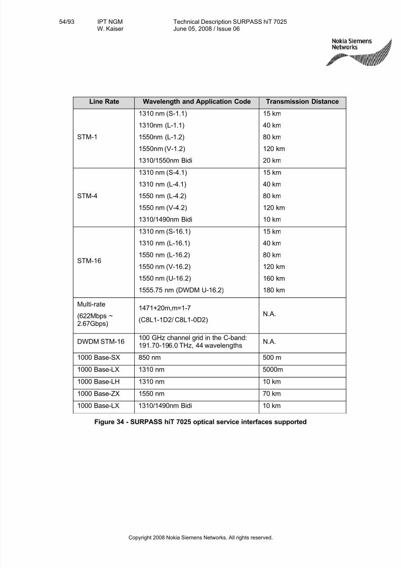
7/27/2019 Surpass Hit 7025 Td
http://slidepdf.com/reader/full/surpass-hit-7025-td 54/93
54/93 IPT NGMW. Kaiser
Technical Description SURPASS hiT 7025June 05, 2008 / Issue 06
Copyright 2008 Nokia Siemens Networks. All rights reserved.
Line Rate Wavelength and Application Code Transmission Distance
STM-1
1310 nm (S-1.1)
1310nm (L-1.1)
1550nm (L-1.2)
1550nm (V-1.2)
1310/1550nm Bidi
15 km
40 km
80 km
120 km
20 km
STM-4
1310 nm (S-4.1)
1310 nm (L-4.1)
1550 nm (L-4.2)1550 nm (V-4.2)
1310/1490nm Bidi
15 km
40 km
80 km120 km
10 km
STM-16
1310 nm (S-16.1)
1310 nm (L-16.1)
1550 nm (L-16.2)
1550 nm (V-16.2)
1550 nm (U-16.2)
1555.75 nm (DWDM U-16.2)
15 km
40 km
80 km
120 km
160 km
180 km
Multi-rate
(622Mbps ~2.67Gbps)
1471+20m,m=1-7
(C8L1-1D2/ C8L1-0D2)N.A.
DWDM STM-16100 GHz channel grid in the C-band:191.70-196.0 THz, 44 wavelengths
N.A.
1000 Base-SX 850 nm 500 m
1000 Base-LX 1310 nm 5000m
1000 Base-LH 1310 nm 10 km
1000 Base-ZX 1550 nm 70 km
1000 Base-LX 1310/1490nm Bidi 10 km
Figure 34 - SURPASS hiT 7025 optical service interfaces supported
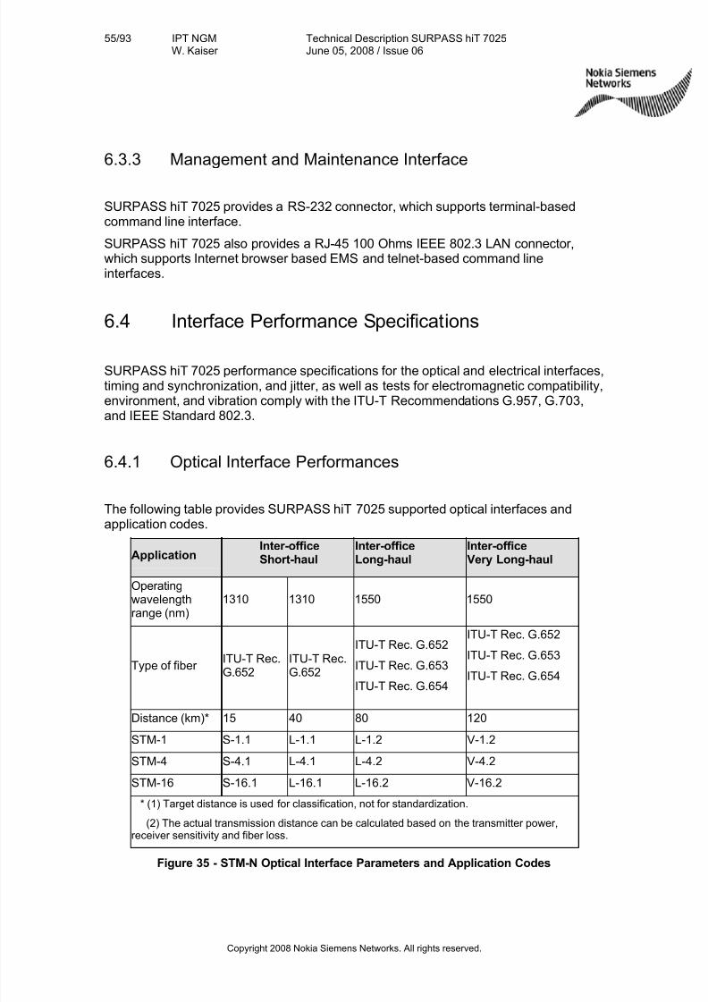
7/27/2019 Surpass Hit 7025 Td
http://slidepdf.com/reader/full/surpass-hit-7025-td 55/93
55/93 IPT NGMW. Kaiser
Technical Description SURPASS hiT 7025June 05, 2008 / Issue 06
Copyright 2008 Nokia Siemens Networks. All rights reserved.
6.3.3 Management and Maintenance Interface
SURPASS hiT 7025 provides a RS-232 connector, which supports terminal-basedcommand line interface.
SURPASS hiT 7025 also provides a RJ-45 100 Ohms IEEE 802.3 LAN connector,which supports Internet browser based EMS and telnet-based command lineinterfaces.
6.4 Interface Performance Specifications
SURPASS hiT 7025 performance specifications for the optical and electrical interfaces,timing and synchronization, and jitter, as well as tests for electromagnetic compatibility,environment, and vibration comply with the ITU-T Recommendations G.957, G.703,and IEEE Standard 802.3.
6.4.1 Optical Interface Performances
The following table provides SURPASS hiT 7025 supported optical interfaces and
application codes.
ApplicationInter-officeShort-haul
Inter-officeLong-haul
Inter-officeVery Long-haul
Operatingwavelengthrange (nm)
1310 1310 1550 1550
Type of fiber ITU-T Rec.G.652
ITU-T Rec.G.652
ITU-T Rec. G.652
ITU-T Rec. G.653
ITU-T Rec. G.654
ITU-T Rec. G.652
ITU-T Rec. G.653
ITU-T Rec. G.654
Distance (km)* 15 40 80 120
STM-1 S-1.1 L-1.1 L-1.2 V-1.2
STM-4 S-4.1 L-4.1 L-4.2 V-4.2
STM-16 S-16.1 L-16.1 L-16.2 V-16.2
* (1) Target distance is used for classification, not for standardization.
(2) The actual transmission distance can be calculated based on the transmitter power,receiver sensitivity and fiber loss.
Figure 35 - STM-N Optical Interface Parameters and Application Codes
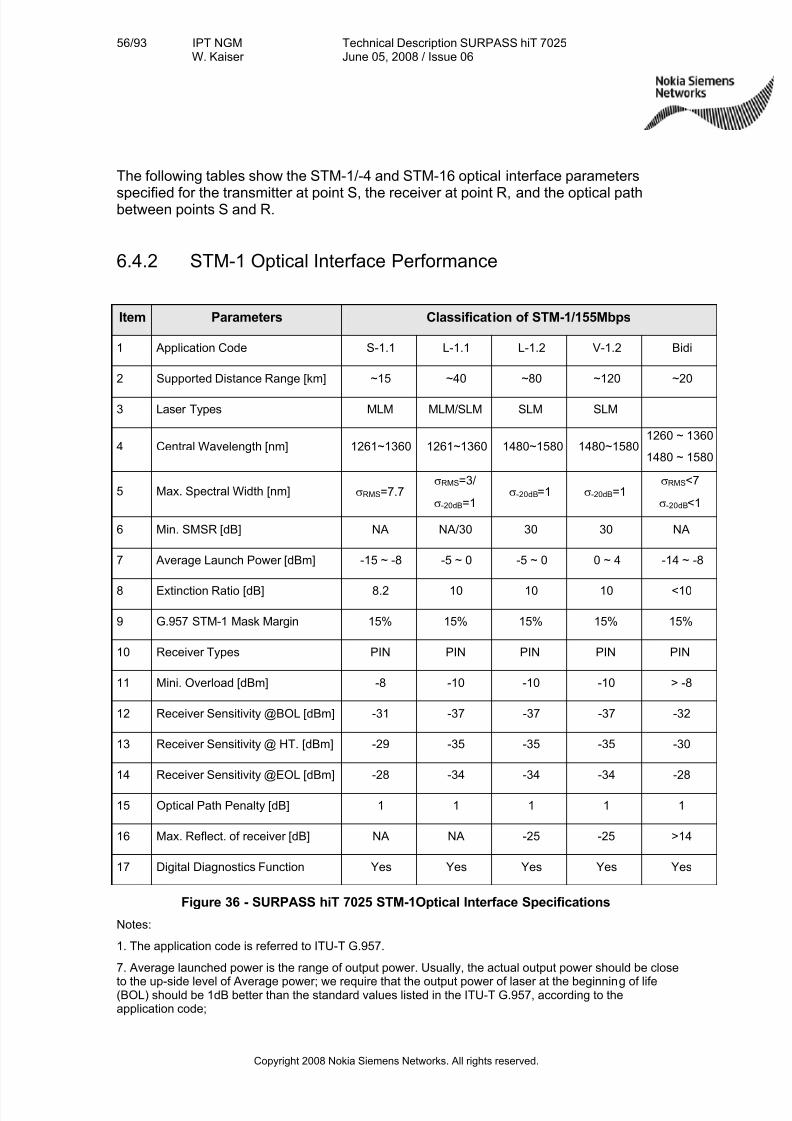
7/27/2019 Surpass Hit 7025 Td
http://slidepdf.com/reader/full/surpass-hit-7025-td 56/93
56/93 IPT NGMW. Kaiser
Technical Description SURPASS hiT 7025June 05, 2008 / Issue 06
Copyright 2008 Nokia Siemens Networks. All rights reserved.
The following tables show the STM-1/-4 and STM-16 optical interface parameters
specified for the transmitter at point S, the receiver at point R, and the optical pathbetween points S and R.
6.4.2 STM-1 Optical Interface Performance
Item Parameters Classification of STM-1/155Mbps
1 Application Code S-1.1 L-1.1 L-1.2 V-1.2 Bidi
2 Supported Distance Range [km] ~15 ~40 ~80 ~120 ~20
3 Laser Types MLM MLM/SLM SLM SLM
4 Central Wavelength [nm] 1261~1360 1261~1360 1480~1580 1480~15801260 ~ 1360
1480 ~ 1580
5 Max. Spectral Width [nm] σRMS=7.7σRMS=3/
σ-20dB=1σ-20dB=1 σ-20dB=1
σRMS<7
σ-20dB<1
6 Min. SMSR [dB] NA NA/30 30 30 NA
7 Average Launch Power [dBm] -15 ~ -8 -5 ~ 0 -5 ~ 0 0 ~ 4 -14 ~ -8
8 Extinction Ratio [dB] 8.2 10 10 10 <10
9 G.957 STM-1 Mask Margin 15% 15% 15% 15% 15%
10 Receiver Types PIN PIN PIN PIN PIN
11 Mini. Overload [dBm] -8 -10 -10 -10 > -8
12 Receiver Sensitivity @BOL [dBm] -31 -37 -37 -37 -32
13 Receiver Sensitivity @ HT. [dBm] -29 -35 -35 -35 -30
14 Receiver Sensitivity @EOL [dBm] -28 -34 -34 -34 -28
15 Optical Path Penalty [dB] 1 1 1 1 1
16 Max. Reflect. of receiver [dB] NA NA -25 -25 >14
17 Digital Diagnostics Function Yes Yes Yes Yes Yes
Figure 36 - SURPASS hiT 7025 STM-1Optical Interface Specifications
Notes:
1. The application code is referred to ITU-T G.957.
7. Average launched power is the range of output power. Usually, the actual output power should be close
to the up-side level of Average power; we require that the output power of laser at the beginning of life(BOL) should be 1dB better than the standard values listed in the ITU-T G.957, according to theapplication code;
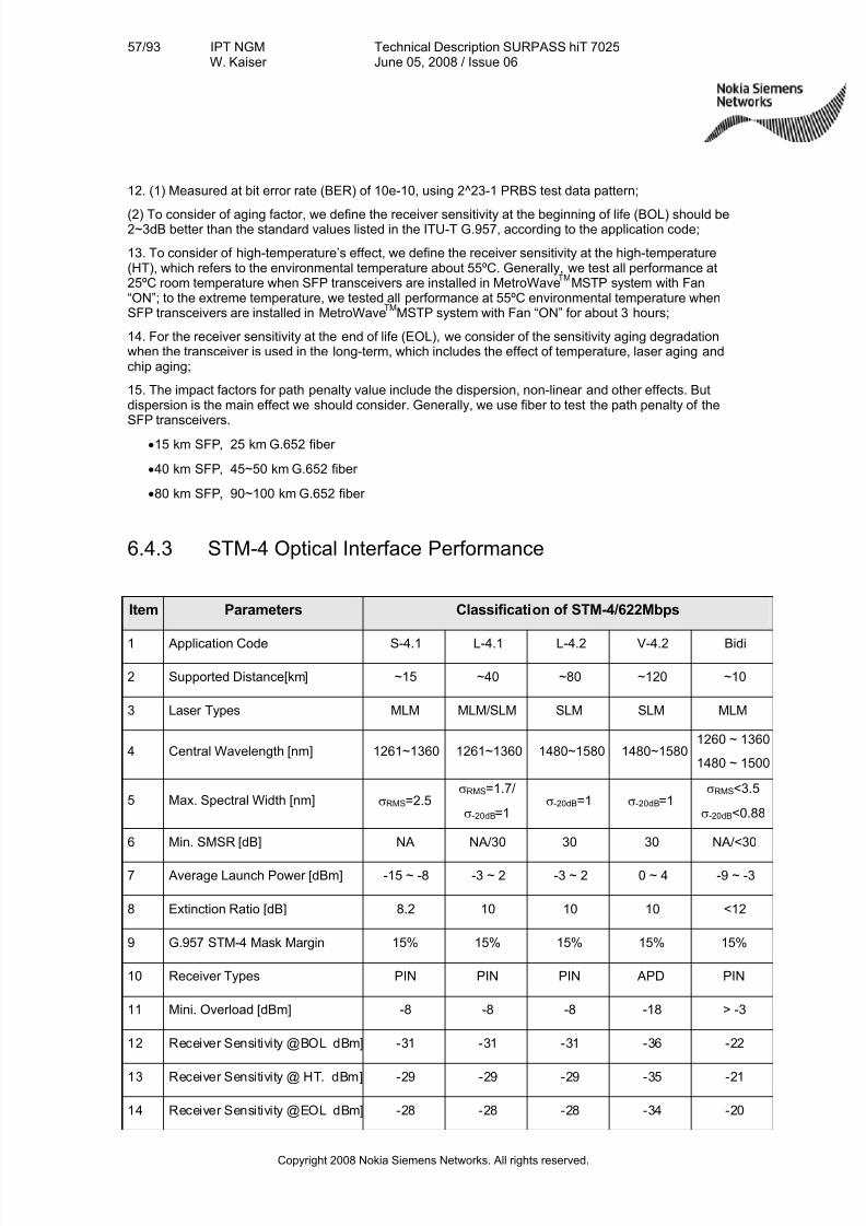
7/27/2019 Surpass Hit 7025 Td
http://slidepdf.com/reader/full/surpass-hit-7025-td 57/93
57/93 IPT NGMW. Kaiser
Technical Description SURPASS hiT 7025June 05, 2008 / Issue 06
Copyright 2008 Nokia Siemens Networks. All rights reserved.
12. (1) Measured at bit error rate (BER) of 10e-10, using 2^23-1 PRBS test data pattern;
(2) To consider of aging factor, we define the receiver sensitivity at the beginning of life (BOL) should be2~3dB better than the standard values listed in the ITU-T G.957, according to the application code;
13. To consider of high-temperature’s effect, we define the receiver sensitivity at the high-temperature(HT), which refers to the environmental temperature about 55ºC. Generally, we test all performance at25ºC room temperature when SFP transceivers are installed in MetroWave
TMMSTP system with Fan
“ON”; to the extreme temperature, we tested all performance at 55ºC environmental temperature whenSFP transceivers are installed in MetroWave
TMMSTP system with Fan “ON” for about 3 hours;
14. For the receiver sensitivity at the end of life (EOL), we consider of the sensitivity aging degradationwhen the transceiver is used in the long-term, which includes the effect of temperature, laser aging andchip aging;
15. The impact factors for path penalty value include the dispersion, non-linear and other effects. Butdispersion is the main effect we should consider. Generally, we use fiber to test the path penalty of theSFP transceivers.
• 15 km SFP, 25 km G.652 fiber
• 40 km SFP, 45~50 km G.652 fiber
• 80 km SFP, 90~100 km G.652 fiber
6.4.3 STM-4 Optical Interface Performance
Item Parameters Classification of STM-4/622Mbps
1 Application Code S-4.1 L-4.1 L-4.2 V-4.2 Bidi
2 Supported Distance[km] ~15 ~40 ~80 ~120 ~10
3 Laser Types MLM MLM/SLM SLM SLM MLM
4 Central Wavelength [nm] 1261~1360 1261~1360 1480~1580 1480~15801260 ~ 1360
1480 ~ 1500
5 Max. Spectral Width [nm] σRMS=2.5σRMS=1.7/
σ-20dB=1σ-20dB=1 σ-20dB=1
σRMS<3.5
σ-20dB<0.88
6 Min. SMSR [dB] NA NA/30 30 30 NA/<30
7 Average Launch Power [dBm] -15 ~ -8 -3 ~ 2 -3 ~ 2 0 ~ 4 -9 ~ -3
8 Extinction Ratio [dB] 8.2 10 10 10 <12
9 G.957 STM-4 Mask Margin 15% 15% 15% 15% 15%
10 Receiver Types PIN PIN PIN APD PIN
11 Mini. Overload [dBm] -8 -8 -8 -18 > -3
12 Receiver Sensitivity @BOL dBm] -31 -31 -31 -36 -22
13 Receiver Sensitivity @ HT. dBm] -29 -29 -29 -35 -21
14 Receiver Sensitivity @EOL dBm] -28 -28 -28 -34 -20
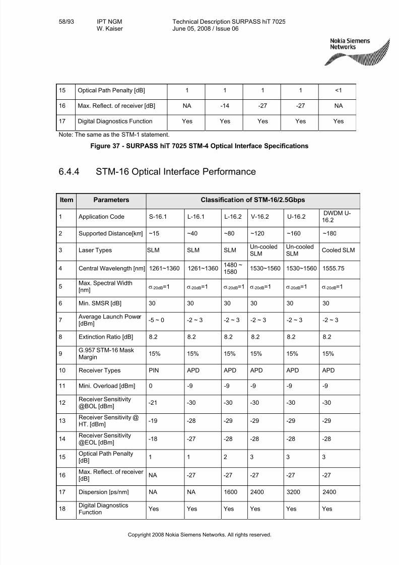
7/27/2019 Surpass Hit 7025 Td
http://slidepdf.com/reader/full/surpass-hit-7025-td 58/93
58/93 IPT NGMW. Kaiser
Technical Description SURPASS hiT 7025June 05, 2008 / Issue 06
Copyright 2008 Nokia Siemens Networks. All rights reserved.
15 Optical Path Penalty [dB] 1 1 1 1 <1
16 Max. Reflect. of receiver [dB] NA -14 -27 -27 NA
17 Digital Diagnostics Function Yes Yes Yes Yes Yes
Note: The same as the STM-1 statement.
Figure 37 - SURPASS hiT 7025 STM-4 Optical Interface Specifications
6.4.4 STM-16 Optical Interface Performance
Item Parameters Classification of STM-16/2.5Gbps
1 Application Code S-16.1 L-16.1 L-16.2 V-16.2 U-16.2DWDM U-16.2
2 Supported Distance[km] ~15 ~40 ~80 ~120 ~160 ~180
3 Laser Types SLM SLM SLMUn-cooledSLM
Un-cooledSLM
Cooled SLM
4 Central Wavelength [nm] 1261~1360 1261~13601480 ~1580
1530~1560 1530~1560 1555.75
5Max. Spectral Width[nm]
σ-20dB=1 σ-20dB=1 σ-20dB=1 σ-20dB=1 σ-20dB=1 σ-20dB=1
6 Min. SMSR [dB] 30 30 30 30 30 30
7 Average Launch Power [dBm]
-5 ~ 0 -2 ~ 3 -2 ~ 3 -2 ~ 3 -2 ~ 3 -2 ~ 3
8 Extinction Ratio [dB] 8.2 8.2 8.2 8.2 8.2 8.2
9G.957 STM-16 MaskMargin
15% 15% 15% 15% 15% 15%
10 Receiver Types PIN APD APD APD APD APD
11 Mini. Overload [dBm] 0 -9 -9 -9 -9 -9
12Receiver Sensitivity@BOL [dBm]
-21 -30 -30 -30 -30 -30
13Receiver Sensitivity @HT. [dBm]
-19 -28 -29 -29 -29 -29
14Receiver Sensitivity@EOL [dBm]
-18 -27 -28 -28 -28 -28
15Optical Path Penalty[dB]
1 1 2 3 3 3
16Max. Reflect. of receiver [dB]
NA -27 -27 -27 -27 -27
17 Dispersion [ps/nm] NA NA 1600 2400 3200 2400
18Digital DiagnosticsFunction
Yes Yes Yes Yes Yes Yes
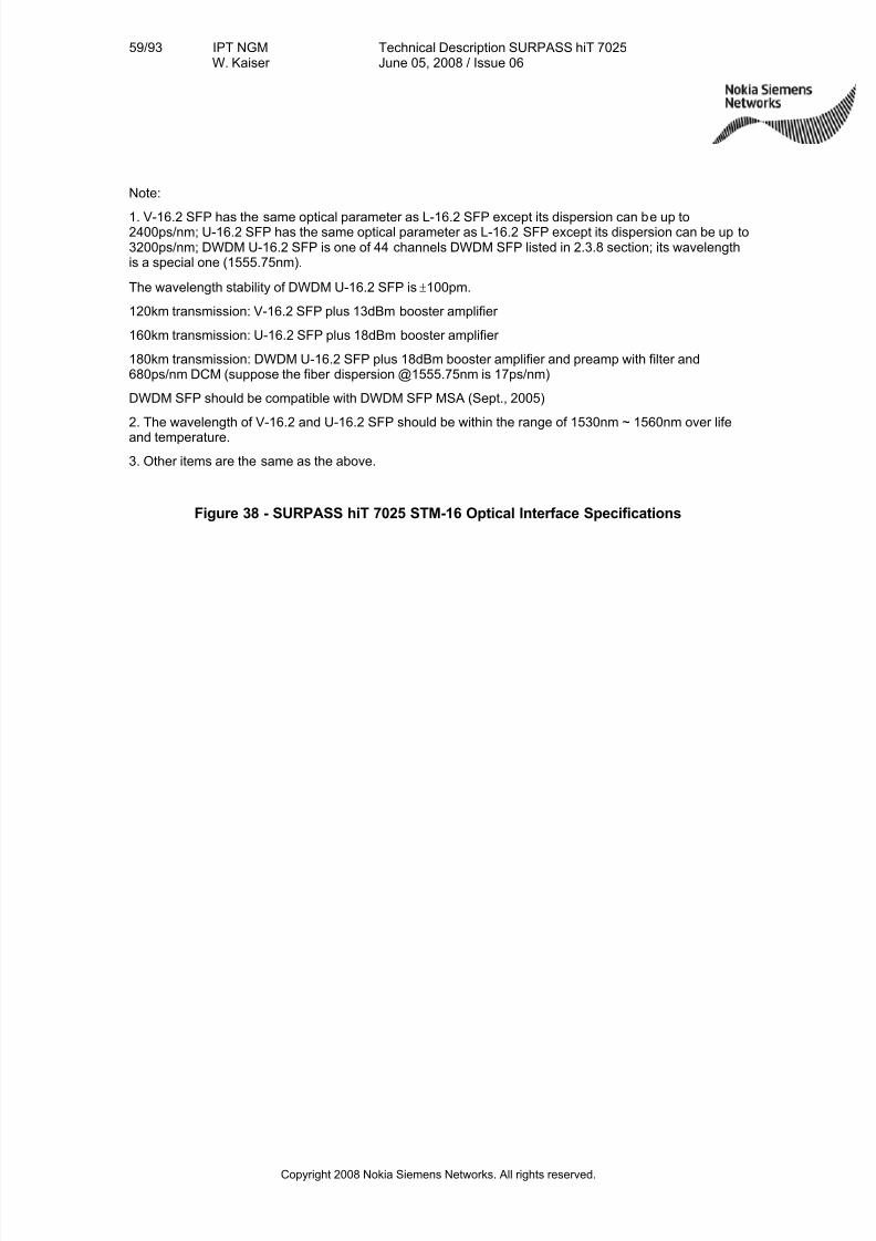
7/27/2019 Surpass Hit 7025 Td
http://slidepdf.com/reader/full/surpass-hit-7025-td 59/93
59/93 IPT NGMW. Kaiser
Technical Description SURPASS hiT 7025June 05, 2008 / Issue 06
Copyright 2008 Nokia Siemens Networks. All rights reserved.
Note:
1. V-16.2 SFP has the same optical parameter as L-16.2 SFP except its dispersion can be up to2400ps/nm; U-16.2 SFP has the same optical parameter as L-16.2 SFP except its dispersion can be up to3200ps/nm; DWDM U-16.2 SFP is one of 44 channels DWDM SFP listed in 2.3.8 section; its wavelengthis a special one (1555.75nm).
The wavelength stability of DWDM U-16.2 SFP is ±100pm.
120km transmission: V-16.2 SFP plus 13dBm booster amplifier
160km transmission: U-16.2 SFP plus 18dBm booster amplifier
180km transmission: DWDM U-16.2 SFP plus 18dBm booster amplifier and preamp with filter and680ps/nm DCM (suppose the fiber dispersion @1555.75nm is 17ps/nm)
DWDM SFP should be compatible with DWDM SFP MSA (Sept., 2005)
2. The wavelength of V-16.2 and U-16.2 SFP should be within the range of 1530nm ~ 1560nm over life
and temperature.
3. Other items are the same as the above.
Figure 38 - SURPASS hiT 7025 STM-16 Optical Interface Specifications
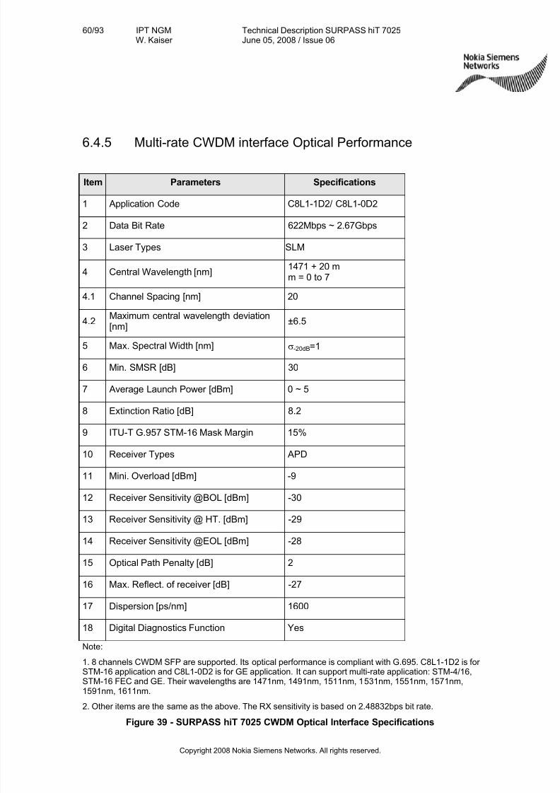
7/27/2019 Surpass Hit 7025 Td
http://slidepdf.com/reader/full/surpass-hit-7025-td 60/93
60/93 IPT NGMW. Kaiser
Technical Description SURPASS hiT 7025June 05, 2008 / Issue 06
Copyright 2008 Nokia Siemens Networks. All rights reserved.
6.4.5 Multi-rate CWDM interface Optical Performance
Item Parameters Specifications
1 Application Code C8L1-1D2/ C8L1-0D2
2 Data Bit Rate 622Mbps ~ 2.67Gbps
3 Laser Types SLM
4 Central Wavelength [nm]1471 + 20 m
m = 0 to 7
4.1 Channel Spacing [nm] 20
4.2Maximum central wavelength deviation[nm]
±6.5
5 Max. Spectral Width [nm] σ-20dB=1
6 Min. SMSR [dB] 30
7 Average Launch Power [dBm] 0 ~ 5
8 Extinction Ratio [dB] 8.2
9 ITU-T G.957 STM-16 Mask Margin 15%
10 Receiver Types APD
11 Mini. Overload [dBm] -9
12 Receiver Sensitivity @BOL [dBm] -30
13 Receiver Sensitivity @ HT. [dBm] -29
14 Receiver Sensitivity @EOL [dBm] -28
15 Optical Path Penalty [dB] 2
16 Max. Reflect. of receiver [dB] -27
17 Dispersion [ps/nm] 1600
18 Digital Diagnostics Function Yes
Note:
1. 8 channels CWDM SFP are supported. Its optical performance is compliant with G.695. C8L1-1D2 is for STM-16 application and C8L1-0D2 is for GE application. It can support multi-rate application: STM-4/16,STM-16 FEC and GE. Their wavelengths are 1471nm, 1491nm, 1511nm, 1531nm, 1551nm, 1571nm,
1591nm, 1611nm.2. Other items are the same as the above. The RX sensitivity is based on 2.48832bps bit rate.
Figure 39 - SURPASS hiT 7025 CWDM Optical Interface Specifications
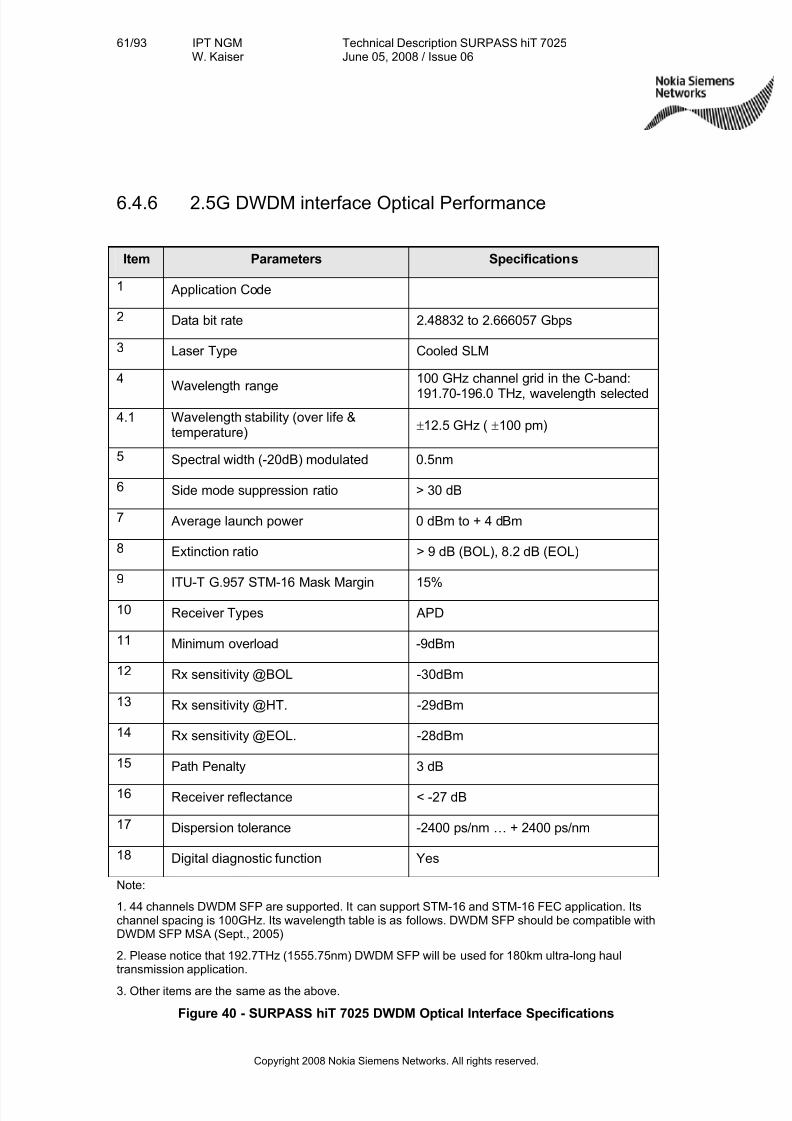
7/27/2019 Surpass Hit 7025 Td
http://slidepdf.com/reader/full/surpass-hit-7025-td 61/93
61/93 IPT NGMW. Kaiser
Technical Description SURPASS hiT 7025June 05, 2008 / Issue 06
Copyright 2008 Nokia Siemens Networks. All rights reserved.
6.4.6 2.5G DWDM interface Optical Performance
Item Parameters Specifications
1 Application Code
2 Data bit rate 2.48832 to 2.666057 Gbps
3 Laser Type Cooled SLM
4
Wavelength range
100 GHz channel grid in the C-band:
191.70-196.0 THz, wavelength selected
4.1 Wavelength stability (over life &temperature)
± 12.5 GHz (± 100 pm)
5 Spectral width (-20dB) modulated 0.5nm
6 Side mode suppression ratio > 30 dB
7 Average launch power 0 dBm to + 4 dBm
8 Extinction ratio > 9 dB (BOL), 8.2 dB (EOL)
9ITU-T G.957 STM-16 Mask Margin 15%
10 Receiver Types APD
11 Minimum overload -9dBm
12 Rx sensitivity @BOL -30dBm
13 Rx sensitivity @HT. -29dBm
14 Rx sensitivity @EOL. -28dBm
15 Path Penalty 3 dB
16 Receiver reflectance < -27 dB
17 Dispersion tolerance -2400 ps/nm … + 2400 ps/nm
18 Digital diagnostic function Yes
Note:
1. 44 channels DWDM SFP are supported. It can support STM-16 and STM-16 FEC application. Itschannel spacing is 100GHz. Its wavelength table is as follows. DWDM SFP should be compatible withDWDM SFP MSA (Sept., 2005)
2. Please notice that 192.7THz (1555.75nm) DWDM SFP will be used for 180km ultra-long haultransmission application.
3. Other items are the same as the above.
Figure 40 - SURPASS hiT 7025 DWDM Optical Interface Specifications
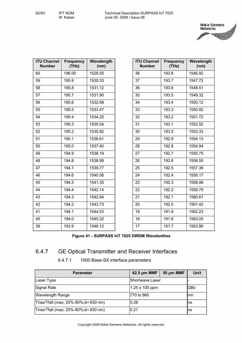
7/27/2019 Surpass Hit 7025 Td
http://slidepdf.com/reader/full/surpass-hit-7025-td 62/93
62/93 IPT NGMW. Kaiser
Technical Description SURPASS hiT 7025June 05, 2008 / Issue 06
Copyright 2008 Nokia Siemens Networks. All rights reserved.
ITU ChannelNumber
Frequency(THz)
Wavelength(nm)
ITU ChannelNumber
Frequency(THz)
Wavelength(nm)
60 196.00 1529.55 38 193.8 1546.92
59 195.9 1530.33 37 193.7 1547.72
58 195.8 1531.12 36 193.6 1548.51
57 195.7 1531.90 35 193.5 1549.32
56 195.6 1532.68 34 193.4 1550.12
55 195.5 1533.47 33 193.3 1550.92
54 195.4 1534.25 32 193.2 1551.72
53 195.3 1535.04 31 193.1 1552.52
52 195.2 1535.82 30 193.0 1553.33
51 195.1 1536.61 29 192.9 1554.13
50 195.0 1537.40 28 192.8 1554.94
49 194.9 1538.19 27 192.7 1555.75
48 194.8 1538.98 26 192.6 1556.55
47 194.7 1539.77 25 192.5 1557.36
46 194.6 1540.56 24 192.4 1558.17
45 194.5 1541.35 23 192.3 1558.98
44 194.4 1542.14 22 192.2 1559.79
43 194.3 1542.94 21 192.1 1560.61
42 194.2 1543.73 20 192.0 1561.42
41 194.1 1544.53 19 191.9 1562.23
40 194.0 1545.32 18 191.8 1563.05
39 193.9 1546.12 17 191.7 1563.86
Figure 41 - SURPASS hiT 7025 DWDM Wavelenthes
6.4.7 GE Optical Transmitter and Receiver Interfaces
6.4.7.1 1000 Base-SX interface parameters
Parameter 62.5 µm MMF 50 µm MMF Unit
Laser Type Shortwave Laser -
Signal Rate 1.25 ± 100 ppm GBd
Wavelength Range 770 to 860 nm
Trise/Tfall (max; 20%-80%;ë> 830 nm) 0.26 ns
Trise/Tfall (max; 20%-80%;ë= 830 nm) 0.21 ns
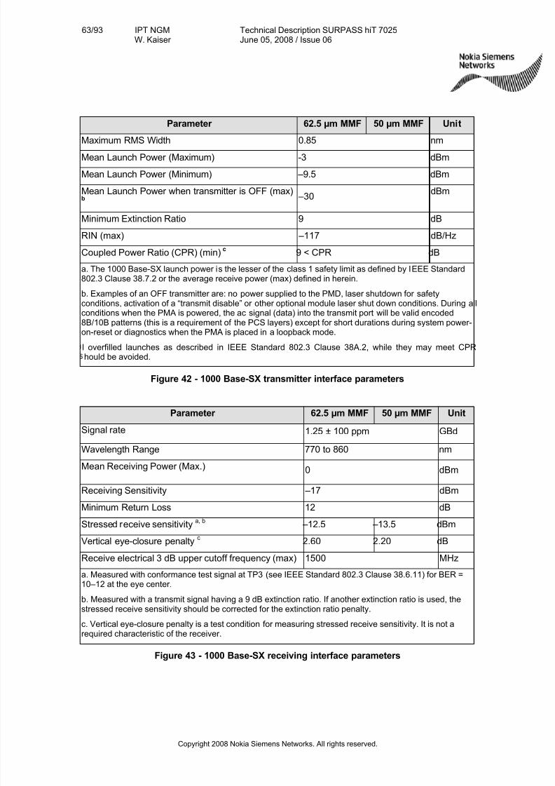
7/27/2019 Surpass Hit 7025 Td
http://slidepdf.com/reader/full/surpass-hit-7025-td 63/93
63/93 IPT NGMW. Kaiser
Technical Description SURPASS hiT 7025June 05, 2008 / Issue 06
Copyright 2008 Nokia Siemens Networks. All rights reserved.
Parameter 62.5 µm MMF 50 µm MMF Unit
Maximum RMS Width 0.85 nm
Mean Launch Power (Maximum) -3 dBm
Mean Launch Power (Minimum) –9.5 dBm
Mean Launch Power when transmitter is OFF (max)
b
–30dBm
Minimum Extinction Ratio 9 dB
RIN (max) –117 dB/Hz
Coupled Power Ratio (CPR) (min)c
9 < CPR dB
a. The 1000 Base-SX launch power is the lesser of the class 1 safety limit as defined by IEEE Standard802.3 Clause 38.7.2 or the average receive power (max) defined in herein.
b. Examples of an OFF transmitter are: no power supplied to the PMD, laser shutdown for safetyconditions, activation of a “transmit disable” or other optional module laser shut down conditions. During allconditions when the PMA is powered, the ac signal (data) into the transmit port will be valid encoded8B/10B patterns (this is a requirement of the PCS layers) except for short durations during system power-on-reset or diagnostics when the PMA is placed in a loopback mode.
l overfilled launches as described in IEEE Standard 802.3 Clause 38A.2, while they may meet CPRhould be avoided.
Figure 42 - 1000 Base-SX transmitter interface parameters
Parameter 62.5 µm MMF 50 µm MMF Unit
Signal rate 1.25 ± 100 ppm GBd
Wavelength Range 770 to 860 nm
Mean Receiving Power (Max.) 0 dBm
Receiving Sensitivity –17 dBm
Minimum Return Loss 12 dB
Stressed receive sensitivitya, b
–12.5 –13.5 dBm
Vertical eye-closure penaltyc
2.60 2.20 dB
Receive electrical 3 dB upper cutoff frequency (max) 1500 MHz
a. Measured with conformance test signal at TP3 (see IEEE Standard 802.3 Clause 38.6.11) for BER =10–12 at the eye center.
b. Measured with a transmit signal having a 9 dB extinction ratio. If another extinction ratio is used, thestressed receive sensitivity should be corrected for the extinction ratio penalty.
c. Vertical eye-closure penalty is a test condition for measuring stressed receive sensitivity. It is not arequired characteristic of the receiver.
Figure 43 - 1000 Base-SX receiving interface parameters
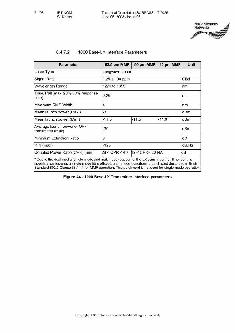
7/27/2019 Surpass Hit 7025 Td
http://slidepdf.com/reader/full/surpass-hit-7025-td 64/93
64/93 IPT NGMW. Kaiser
Technical Description SURPASS hiT 7025June 05, 2008 / Issue 06
Copyright 2008 Nokia Siemens Networks. All rights reserved.
6.4.7.2 1000 Base-LX Interface Parameters
Parameter 62.5 µm MMF 50 µm MMF 10 µm MMF Unit
Laser Type Longwave Laser
Signal Rate 1.25 ± 100 ppm GBd
Wavelength Range 1270 to 1355 nm
Trise/Tfall (max; 20%-80% responsetime)
0.26 ns
Maximum RMS Width 4 nm
Mean launch power (Max.) -3 dBm
Mean launch power (Min.) -11.5 -11.5 -11.0 dBm
Average launch power of OFFtransmitter (max)
-30 dBm
Minimum Extinction Ratio 9 dB
RIN (max) -120 dB/Hz
Coupled Power Ratio (CPR) (min)*
28 < CPR < 40 12 < CPR< 20 NA dB
* Due to the dual media (single-mode and multimode) support of the LX transmitter, fulfillment of thisspecification requires a single-mode fibre offset-launch mode-conditioning patch cord described in IEEEStandard 802.3 Clause 38.11.4 for MMF operation. This patch cord is not used for single-mode operation.
Figure 44 - 1000 Base-LX Transmitter interface parameters
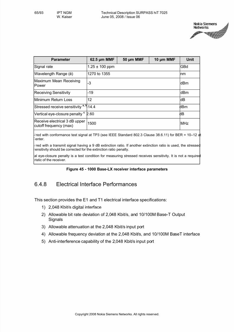
7/27/2019 Surpass Hit 7025 Td
http://slidepdf.com/reader/full/surpass-hit-7025-td 65/93
65/93 IPT NGMW. Kaiser
Technical Description SURPASS hiT 7025June 05, 2008 / Issue 06
Copyright 2008 Nokia Siemens Networks. All rights reserved.
Parameter 62.5 µm MMF 50 µm MMF 10 µm MMF Unit
Signal rate 1.25 ± 100 ppm GBd
Wavelength Range (ë) 1270 to 1355 nm
Maximum Mean ReceivingPower
-3 dBm
Receiving Sensitivity -19 dBm
Minimum Return Loss 12 dB
Stressed receive sensitivitya, b
-14.4 dBm
Vertical eye-closure penaltyc
2.60 dB
Receive electrical 3 dB upper cutoff frequency (max)
1500 MHz
red with conformance test signal at TP3 (see IEEE Standard 802.3 Clause 38.6.11) for BER = 10–12 atenter.
red with a transmit signal having a 9 dB extinction ratio. If another extinction ratio is used, the stressedensitivity should be corrected for the extinction ratio penalty.
al eye-closure penalty is a test condition for measuring stressed receives sensitivity. It is not a requiredristic of the receiver.
Figure 45 - 1000 Base-LX receiver interface parameters
6.4.8 Electrical Interface Performances
This section provides the E1 and T1 electrical interface specifications:
1) 2,048 Kbit/s digital interface
2) Allowable bit rate deviation of 2,048 Kbit/s, and 10/100M Base-T OutputSignals
3) Allowable attenuation at the 2,048 Kbit/s input port
4) Allowable frequency deviation at the 2,048 Kbit/s, and 10/100M BaseT interface
5) Anti-interference capability of the 2,048 Kbit/s input port
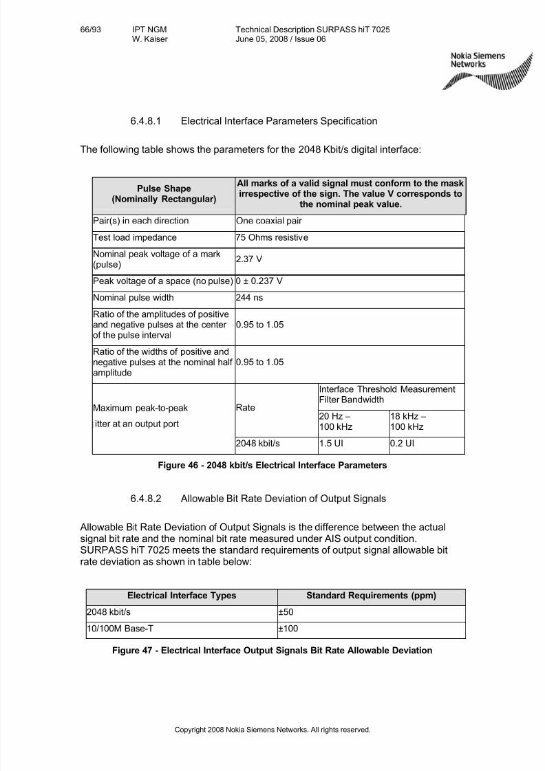
7/27/2019 Surpass Hit 7025 Td
http://slidepdf.com/reader/full/surpass-hit-7025-td 66/93
66/93 IPT NGMW. Kaiser
Technical Description SURPASS hiT 7025June 05, 2008 / Issue 06
Copyright 2008 Nokia Siemens Networks. All rights reserved.
6.4.8.1 Electrical Interface Parameters Specification
The following table shows the parameters for the 2048 Kbit/s digital interface:
Pulse Shape(Nominally Rectangular)
All marks of a valid signal must conform to the maskirrespective of the sign. The value V corresponds to
the nominal peak value.
Pair(s) in each direction One coaxial pair
Test load impedance 75 Ohms resistive
Nominal peak voltage of a mark(pulse)
2.37 V
Peak voltage of a space (no pulse) 0 ± 0.237 V
Nominal pulse width 244 ns
Ratio of the amplitudes of positiveand negative pulses at the center of the pulse interval
0.95 to 1.05
Ratio of the widths of positive andnegative pulses at the nominal half amplitude
0.95 to 1.05
Interface Threshold MeasurementFilter Bandwidth
Rate20 Hz –100 kHz
18 kHz –100 kHz
Maximum peak-to-peak
itter at an output port
2048 kbit/s 1.5 UI 0.2 UI
Figure 46 - 2048 kbit/s Electrical Interface Parameters
6.4.8.2 Allowable Bit Rate Deviation of Output Signals
Allowable Bit Rate Deviation of Output Signals is the difference between the actual
signal bit rate and the nominal bit rate measured under AIS output condition.SURPASS hiT 7025 meets the standard requirements of output signal allowable bitrate deviation as shown in table below:
Electrical Interface Types Standard Requirements (ppm)
2048 kbit/s ±50
10/100M Base-T ±100
Figure 47 - Electrical Interface Output Signals Bit Rate Allowable Deviation
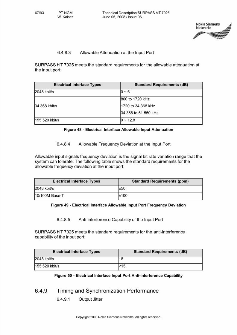
7/27/2019 Surpass Hit 7025 Td
http://slidepdf.com/reader/full/surpass-hit-7025-td 67/93
67/93 IPT NGMW. Kaiser
Technical Description SURPASS hiT 7025June 05, 2008 / Issue 06
Copyright 2008 Nokia Siemens Networks. All rights reserved.
6.4.8.3 Allowable Attenuation at the Input Port
SURPASS hiT 7025 meets the standard requirements for the allowable attenuation atthe input port:
Electrical Interface Types Standard Requirements (dB)
2048 kbit/s 0 ~ 6
34 368 kbit/s
860 to 1720 kHz
1720 to 34 368 kHz
34 368 to 51 550 kHz
155 520 kbit/s 0 ~ 12.8
Figure 48 - Electrical Interface Allowable Input Attenuation
6.4.8.4 Allowable Frequency Deviation at the Input Port
Allowable input signals frequency deviation is the signal bit rate variation range that thesystem can tolerate. The following table shows the standard requirements for theallowable frequency deviation at the input port:
Electrical Interface Types Standard Requirements (ppm)
2048 kbit/s ±50
10/100M Base-T ±100
Figure 49 - Electrical Interface Allowable Input Port Frequency Deviation
6.4.8.5 Anti-interference Capability of the Input Port
SURPASS hiT 7025 meets the standard requirements for the anti-interferencecapability of the input port:
Electrical Interface Types Standard Requirements (dB)
2048 kbit/s 18
155 520 kbit/s ≥15
Figure 50 - Electrical Interface Input Port Anti-interference Capability
6.4.9 Timing and Synchronization Performance6.4.9.1 Output Jitter
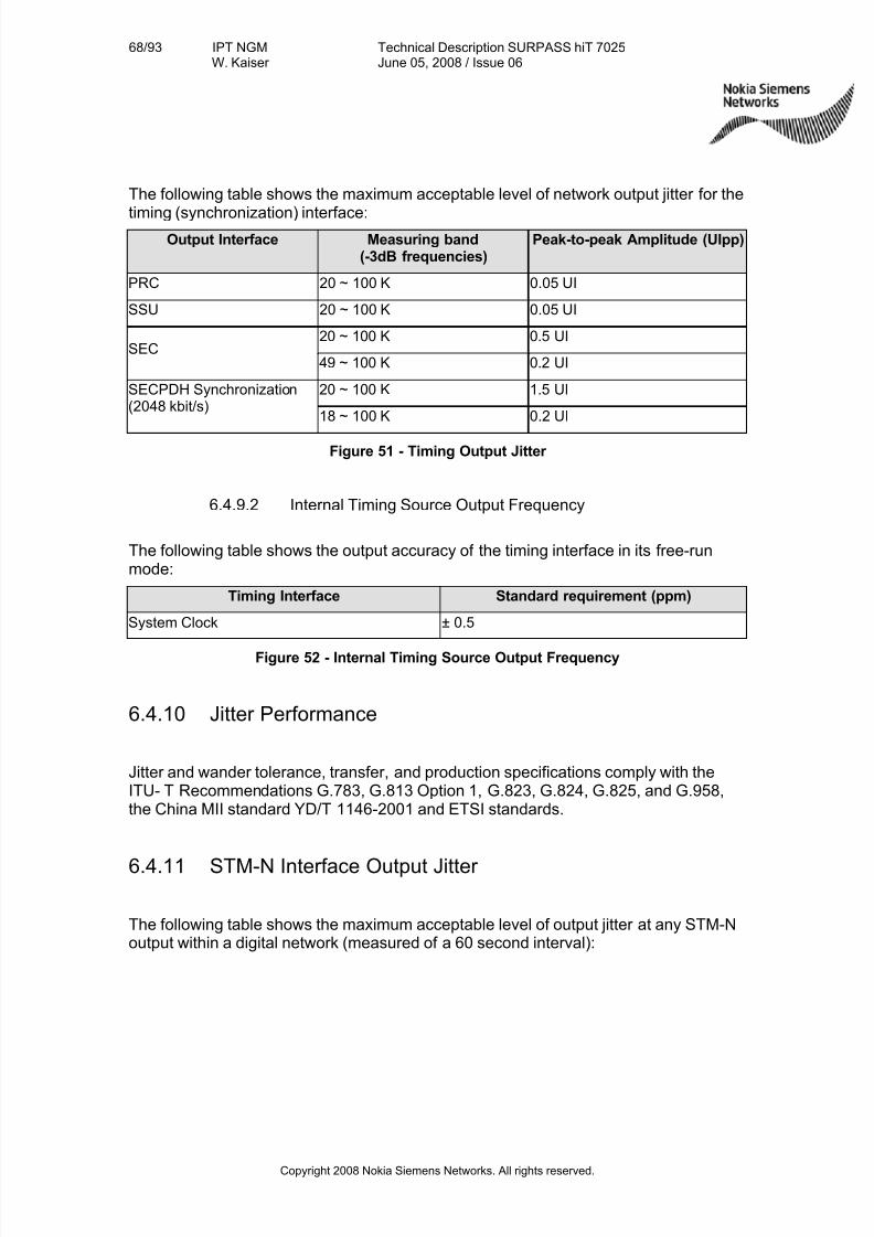
7/27/2019 Surpass Hit 7025 Td
http://slidepdf.com/reader/full/surpass-hit-7025-td 68/93
68/93 IPT NGMW. Kaiser
Technical Description SURPASS hiT 7025June 05, 2008 / Issue 06
Copyright 2008 Nokia Siemens Networks. All rights reserved.
The following table shows the maximum acceptable level of network output jitter for the
timing (synchronization) interface:Output Interface Measuring band
(-3dB frequencies)Peak-to-peak Amplitude (UIpp)
PRC 20 ~ 100 K 0.05 UI
SSU 20 ~ 100 K 0.05 UI
20 ~ 100 K 0.5 UISEC
49 ~ 100 K 0.2 UI
20 ~ 100 K 1.5 UISECPDH Synchronization(2048 kbit/s)
18 ~ 100 K 0.2 UI
Figure 51 - Timing Output Jitter
6.4.9.2 Internal Timing Source Output Frequency
The following table shows the output accuracy of the timing interface in its free-runmode:
Timing Interface Standard requirement (ppm)
System Clock ± 0.5
Figure 52 - Internal Timing Source Output Frequency
6.4.10 Jitter Performance
Jitter and wander tolerance, transfer, and production specifications comply with theITU- T Recommendations G.783, G.813 Option 1, G.823, G.824, G.825, and G.958,the China MII standard YD/T 1146-2001 and ETSI standards.
6.4.11 STM-N Interface Output Jitter
The following table shows the maximum acceptable level of output jitter at any STM-Noutput within a digital network (measured of a 60 second interval):
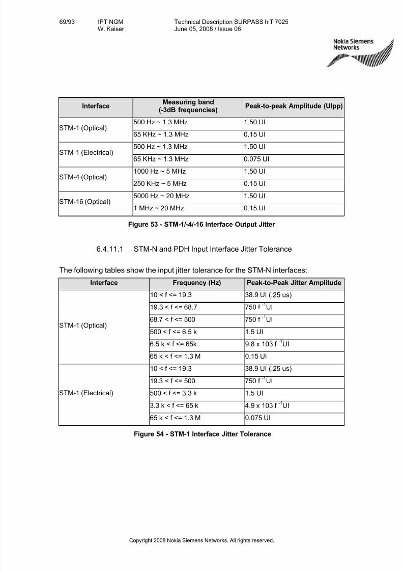
7/27/2019 Surpass Hit 7025 Td
http://slidepdf.com/reader/full/surpass-hit-7025-td 69/93
69/93 IPT NGMW. Kaiser
Technical Description SURPASS hiT 7025June 05, 2008 / Issue 06
Copyright 2008 Nokia Siemens Networks. All rights reserved.
InterfaceMeasuring band
(-3dB frequencies)Peak-to-peak Amplitude (UIpp)
500 Hz ~ 1.3 MHz 1.50 UISTM-1 (Optical)
65 KHz ~ 1.3 MHz 0.15 UI
500 Hz ~ 1.3 MHz 1.50 UISTM-1 (Electrical)
65 KHz ~ 1.3 MHz 0.075 UI
1000 Hz ~ 5 MHz 1.50 UISTM-4 (Optical)
250 KHz ~ 5 MHz 0.15 UI
5000 Hz ~ 20 MHz 1.50 UISTM-16 (Optical)
1 MHz ~ 20 MHz 0.15 UI
Figure 53 - STM-1/-4/-16 Interface Output Jitter
6.4.11.1 STM-N and PDH Input Interface Jitter Tolerance
The following tables show the input jitter tolerance for the STM-N interfaces:
Interface Frequency (Hz) Peak-to-Peak Jitter Amplitude
10 < f <= 19.3 38.9 UI (.25 us)
19.3 < f <= 68.7 750 f -1
UI
68.7 < f <= 500 750 f -1
UI
500 < f <= 6.5 k 1.5 UI
6.5 k < f <= 65k 9.8 x 10³ f -1
UI
STM-1 (Optical)
65 k < f <= 1.3 M 0.15 UI
10 < f <= 19.3 38.9 UI (.25 us)
19.3 < f <= 500 750 f -1
UI
500 < f <= 3.3 k 1.5 UI
3.3 k < f <= 65 k 4.9 x 10³ f -1
UI
STM-1 (Electrical)
65 k < f <= 1.3 M 0.075 UI
Figure 54 - STM-1 Interface Jitter Tolerance
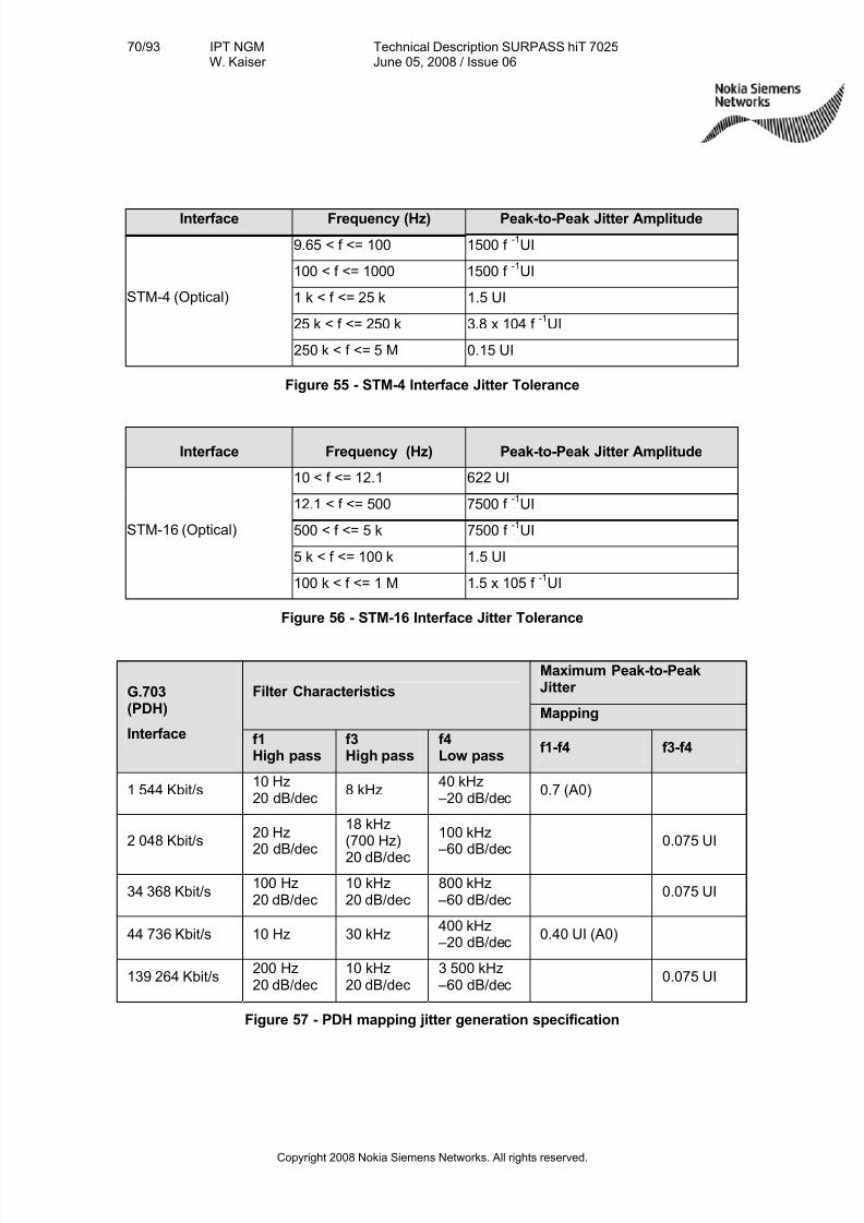
7/27/2019 Surpass Hit 7025 Td
http://slidepdf.com/reader/full/surpass-hit-7025-td 70/93
70/93 IPT NGMW. Kaiser
Technical Description SURPASS hiT 7025June 05, 2008 / Issue 06
Copyright 2008 Nokia Siemens Networks. All rights reserved.
Interface Frequency (Hz) Peak-to-Peak Jitter Amplitude
9.65 < f <= 100 1500 f -1
UI
100 < f <= 1000 1500 f -1
UI
1 k < f <= 25 k 1.5 UI
25 k < f <= 250 k 3.8 x 10⁴ f -1
UI
STM-4 (Optical)
250 k < f <= 5 M 0.15 UI
Figure 55 - STM-4 Interface Jitter Tolerance
Interface Frequency (Hz) Peak-to-Peak Jitter Amplitude
10 < f <= 12.1 622 UI
12.1 < f <= 500 7500 f P-1
PUI
500 < f <= 5 k 7500 f P-1
PUI
5 k < f <= 100 k 1.5 UI
STM-16 (Optical)
100 k < f <= 1 M 1.5 x 10⁵ f P-1
PPPUI
Figure 56 - STM-16 Interface Jitter Tolerance
Maximum Peak-to-PeakJitter Filter Characteristics
Mapping
G.703(PDH)
Interface f1High pass
f3High pass
f4Low pass
f1-f4 f3-f4
1 544 Kbit/s10 Hz20 dB/dec
8 kHz40 kHz –20 dB/dec
0.7 (A0)
2 048 Kbit/s20 Hz20 dB/dec
18 kHz(700 Hz)
20 dB/dec
100 kHz –60 dB/dec
0.075 UI
34 368 Kbit/s100 Hz20 dB/dec
10 kHz20 dB/dec
800 kHz –60 dB/dec
0.075 UI
44 736 Kbit/s 10 Hz 30 kHz400 kHz –20 dB/dec
0.40 UI (A0)
139 264 Kbit/s200 Hz20 dB/dec
10 kHz20 dB/dec
3 500 kHz –60 dB/dec
0.075 UI
Figure 57 - PDH mapping jitter generation specification
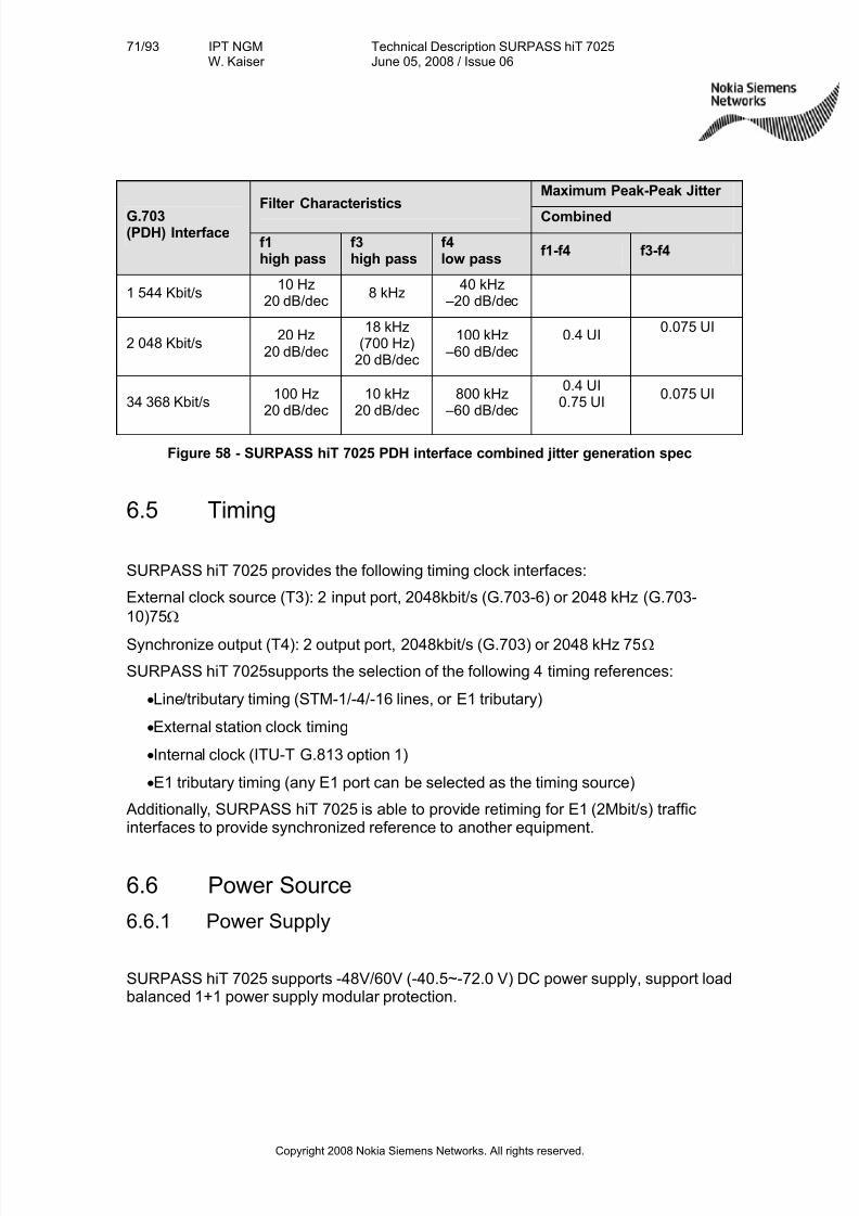
7/27/2019 Surpass Hit 7025 Td
http://slidepdf.com/reader/full/surpass-hit-7025-td 71/93
71/93 IPT NGMW. Kaiser
Technical Description SURPASS hiT 7025June 05, 2008 / Issue 06
Copyright 2008 Nokia Siemens Networks. All rights reserved.
Maximum Peak-Peak Jitter Filter Characteristics
CombinedG.703(PDH) Interface
f1high pass
f3high pass
f4low pass
f1-f4 f3-f4
1 544 Kbit/s10 Hz
20 dB/dec8 kHz
40 kHz –20 dB/dec
2 048 Kbit/s20 Hz
20 dB/dec
18 kHz(700 Hz)
20 dB/dec
100 kHz –60 dB/dec
0.4 UI0.075 UI
34 368 Kbit/s100 Hz
20 dB/dec10 kHz
20 dB/dec800 kHz
–60 dB/dec
0.4 UI0.75 UI
0.075 UI
Figure 58 - SURPASS hiT 7025 PDH interface combined jitter generation spec
6.5 Timing
SURPASS hiT 7025 provides the following timing clock interfaces:
External clock source (T3): 2 input port, 2048kbit/s (G.703-6) or 2048 kHz (G.703-
10)75Ω
Synchronize output (T4): 2 output port, 2048kbit/s (G.703) or 2048 kHz 75Ω
SURPASS hiT 7025supports the selection of the following 4 timing references:
• Line/tributary timing (STM-1/-4/-16 lines, or E1 tributary)
•External station clock timing
• Internal clock (ITU-T G.813 option 1)
•E1 tributary timing (any E1 port can be selected as the timing source)
Additionally, SURPASS hiT 7025 is able to provide retiming for E1 (2Mbit/s) trafficinterfaces to provide synchronized reference to another equipment.
6.6 Power Source
6.6.1 Power Supply
SURPASS hiT 7025 supports -48V/60V (-40.5~-72.0 V) DC power supply, support loadbalanced 1+1 power supply modular protection.
7/27/2019 Surpass Hit 7025 Td
http://slidepdf.com/reader/full/surpass-hit-7025-td 72/93
72/93 IPT NGMW. Kaiser
Technical Description SURPASS hiT 7025June 05, 2008 / Issue 06
Copyright 2008 Nokia Siemens Networks. All rights reserved.
6.6.2 Power Consumption
Maximum power consumption: 210W (Full Configuration)
Average power consumption: 122W (Typical Configuration)
6.6.3 Cooling
The equipment is assembled with one fan unit. It is field replaceable. Fan failure doesnot affect service.
6.7 Mechanical Structure
SURPASS hiT 7025 chassis mechanical parameters:
•Height: 238mm (5U)
•Width: 445mm
•Depth: 240mm (300 mm back-to-door)
SURPASS hiT 7025 can be installed in the following types of racks:
•EIA 310 19”
• 2200mm(Height) × 600mm (Width) × 300mm (Depth)
• 2600mm(Height)×600mm(Width)×300mm(Depth)
Depending on the electrical cabel load you can install up to six SURPASS hiT 7025chassis into a 2200mm high ETSI rack or an EIA 310 19” rack ( typically four systemsper rack ).
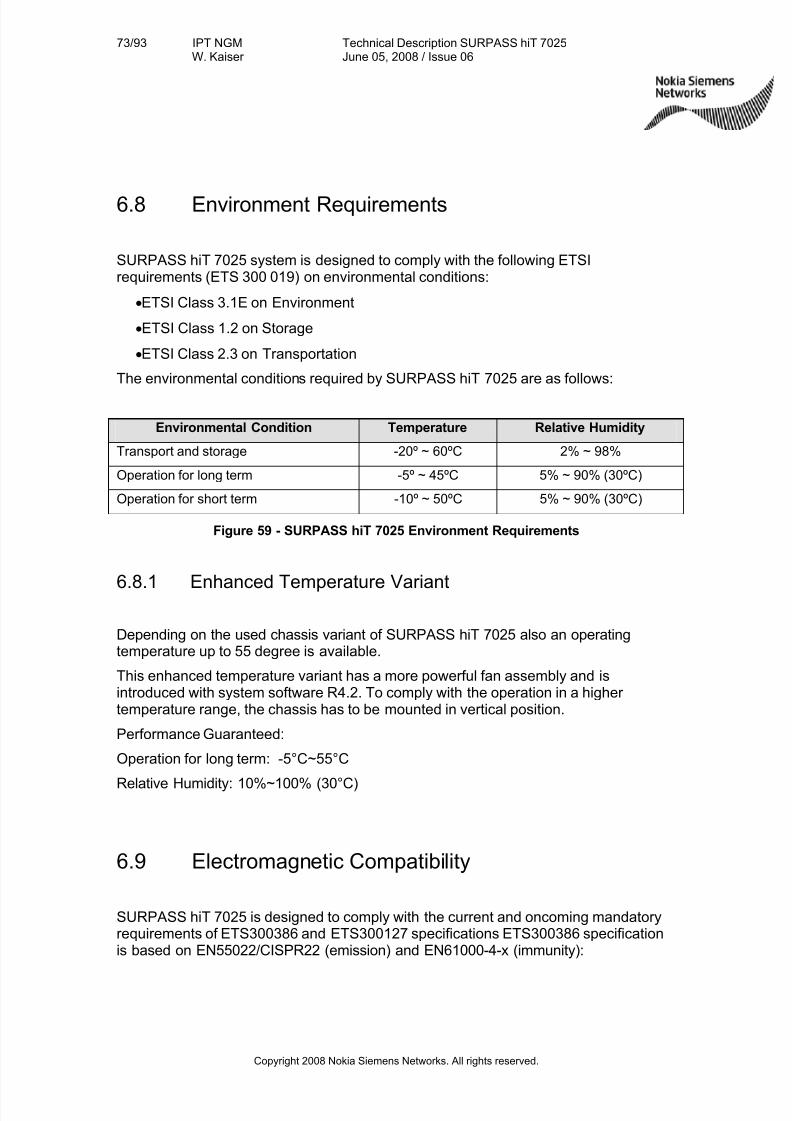
7/27/2019 Surpass Hit 7025 Td
http://slidepdf.com/reader/full/surpass-hit-7025-td 73/93
73/93 IPT NGMW. Kaiser
Technical Description SURPASS hiT 7025June 05, 2008 / Issue 06
Copyright 2008 Nokia Siemens Networks. All rights reserved.
6.8 Environment Requirements
SURPASS hiT 7025 system is designed to comply with the following ETSIrequirements (ETS 300 019) on environmental conditions:
•ETSI Class 3.1E on Environment
•ETSI Class 1.2 on Storage
•ETSI Class 2.3 on Transportation
The environmental conditions required by SURPASS hiT 7025 are as follows:
Environmental Condition Temperature Relative Humidity
Transport and storage -20º ~ 60ºC 2% ~ 98%
Operation for long term -5º ~ 45ºC 5% ~ 90% (30ºC)
Operation for short term -10º ~ 50ºC 5% ~ 90% (30ºC)
Figure 59 - SURPASS hiT 7025 Environment Requirements
6.8.1 Enhanced Temperature Variant
Depending on the used chassis variant of SURPASS hiT 7025 also an operatingtemperature up to 55 degree is available.
This enhanced temperature variant has a more powerful fan assembly and isintroduced with system software R4.2. To comply with the operation in a higher temperature range, the chassis has to be mounted in vertical position.
Performance Guaranteed:
Operation for long term: -5°C~55°C
Relative Humidity: 10%~100% (30°C)
6.9 Electromagnetic Compatibility
SURPASS hiT 7025 is designed to comply with the current and oncoming mandatoryrequirements of ETS300386 and ETS300127 specifications ETS300386 specificationis based on EN55022/CISPR22 (emission) and EN61000-4-x (immunity):
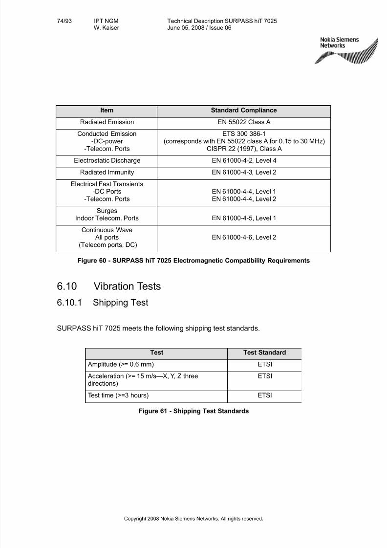
7/27/2019 Surpass Hit 7025 Td
http://slidepdf.com/reader/full/surpass-hit-7025-td 74/93
74/93 IPT NGMW. Kaiser
Technical Description SURPASS hiT 7025June 05, 2008 / Issue 06
Copyright 2008 Nokia Siemens Networks. All rights reserved.
Item Standard Compliance
Radiated Emission EN 55022 Class A
Conducted Emission-DC-power
-Telecom. Ports
ETS 300 386-1(corresponds with EN 55022 class A for 0.15 to 30 MHz)
CISPR 22 (1997), Class A
Electrostatic Discharge EN 61000-4-2, Level 4
Radiated Immunity EN 61000-4-3, Level 2
Electrical Fast Transients
-DC Ports-Telecom. Ports
EN 61000-4-4, Level 1EN 61000-4-4, Level 2
SurgesIndoor Telecom. Ports EN 61000-4-5, Level 1
Continuous Wave All ports
(Telecom ports, DC)EN 61000-4-6, Level 2
Figure 60 - SURPASS hiT 7025 Electromagnetic Compatibility Requirements
6.10 Vibration Tests6.10.1 Shipping Test
SURPASS hiT 7025 meets the following shipping test standards.
Test Test Standard
Amplitude (>= 0.6 mm) ETSI
Acceleration (>= 15 m/s—X, Y, Z three
directions)
ETSI
Test time (>=3 hours) ETSI
Figure 61 - Shipping Test Standards

7/27/2019 Surpass Hit 7025 Td
http://slidepdf.com/reader/full/surpass-hit-7025-td 75/93
75/93 IPT NGMW. Kaiser
Technical Description SURPASS hiT 7025June 05, 2008 / Issue 06
Copyright 2008 Nokia Siemens Networks. All rights reserved.
6.10.2 Office Test
SURPASS hiT 7025 meets the following office test standards.
Test Test Standard
Amplitude (>= 0.6 mm) ETSI
Acceleration (>= 15 m/s—X, Y, Z three directions) ETSI
Test time (>= 3 hours) ETSI
Figure 62 - Office test standards
6.11 Alarms and Events
6.11.1 Alarm Types
There are five types of failure in the system:
• Communication Failure: Failures related to communication status (such as
LOS, LOF, AIS, DEG and LAN) or other communication protocol relatedfailures (such as, STMfLOS).
• Quality of Service Failure: Failure related to system performance, such asresponding time too long, threshold crossing, and performance degrading.
• Equipment Failure: Failures related to the hardware equipment, such aspower system defect, timing interface failures, processor defect,transmit/receiver equipment defect or any other equipment component faults(such as, EQfFLT).
• Processing Error Failure: Failures related to the software, memory overflow,version incompatibility, software errors, program illegal interruption, NE
configuration errors and NE inaccessible.
• Environmental Failure: Failures related to environment changes, such asunacceptable temperature and humidity, ventilation or cooling system faults,excessive vibration, and door open/close.
7/27/2019 Surpass Hit 7025 Td
http://slidepdf.com/reader/full/surpass-hit-7025-td 76/93
76/93 IPT NGMW. Kaiser
Technical Description SURPASS hiT 7025June 05, 2008 / Issue 06
Copyright 2008 Nokia Siemens Networks. All rights reserved.
6.11.2 Alarm Severity Level
There are five alarm severity levels defined in the system:
• Critical—Service-interrupting alarms.
• Major —Service-affecting alarms.
• Minor —Non-Service-affecting alarms, but can potentially become service-affecting alarms. You need to perform fault inspection and any necessary fixesto prevent it from becoming worse.
• Warning—Non-Service-affecting, information presented to the operator for thepurpose of maintenance.
• Indeterminate—The alarm severity level is undefined.
The system has a red LED alarm indicator for Prompt (service-affecting) and a yellowLED alarm indicator for Deferred/Info (non-service-affecting).
6.11.3 Alarm Reports
The Element Management software logs the 10,000 latest failures in the alarm log andindependently reports the failure status change to the EMS. SURPASS hiT 7025allows users to query alarm logs using a variety of criteria.
6.11.4 Events
There are three types of events defined in the system: Management, Hardware, andSoftware. SURPASS hiT 7025 requires every event to be time-stamped.
An Event (as defined by ITU-T Recommendation M.2410) is an instantaneousoccurrence that changes the global status of an object. This status change may bepersistent or temporary, allowing for surveillance, monitoring, and performancemeasurement functionality, etc. Events may or may not generate reports; they may bespontaneous or planned; they may trigger other events or may be triggered by one or more other events. (Recommendation M.60)
6.11.4.1 Management Events
The attributes of the management events include: Event name, Timestamp, User nameand privilege level, and Description.
Name Description
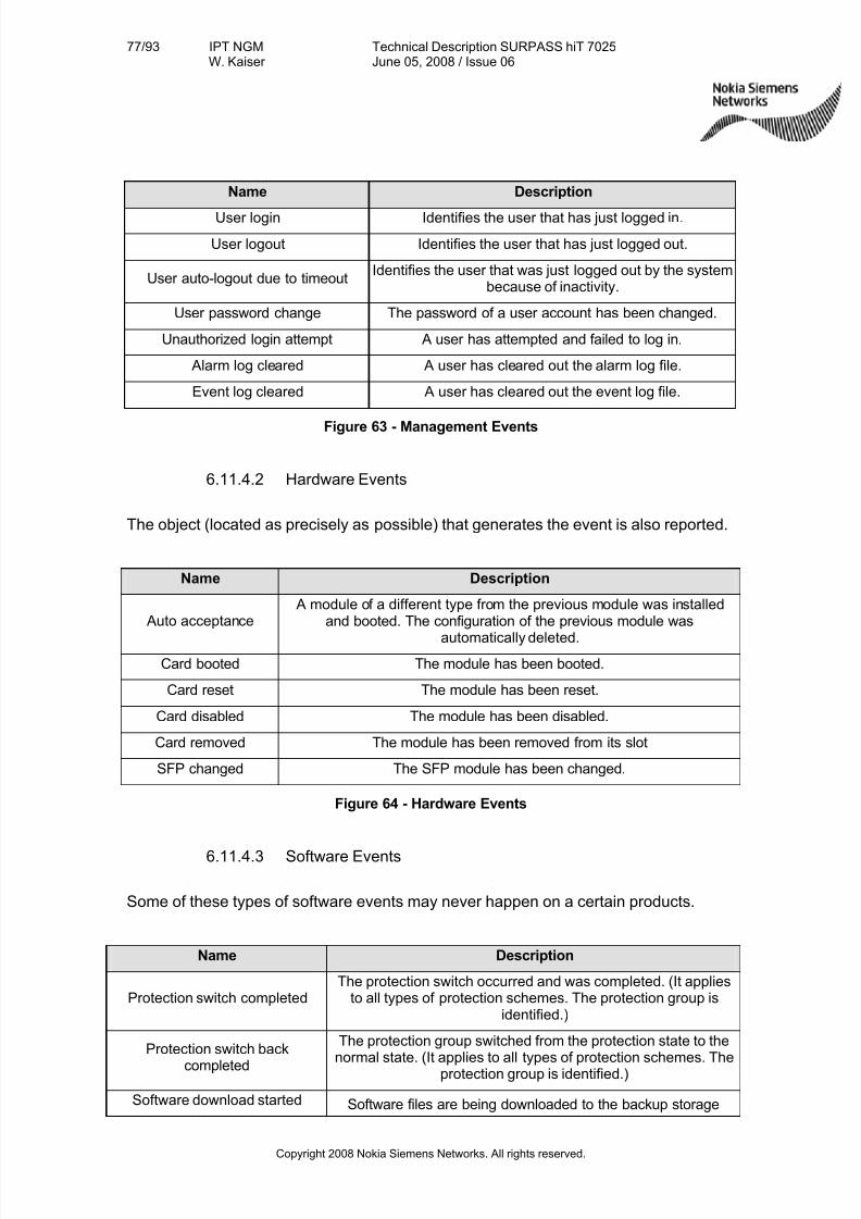
7/27/2019 Surpass Hit 7025 Td
http://slidepdf.com/reader/full/surpass-hit-7025-td 77/93
77/93 IPT NGMW. Kaiser
Technical Description SURPASS hiT 7025June 05, 2008 / Issue 06
Copyright 2008 Nokia Siemens Networks. All rights reserved.
Name Description
User login Identifies the user that has just logged in.
User logout Identifies the user that has just logged out.
User auto-logout due to timeoutIdentifies the user that was just logged out by the system
because of inactivity.
User password change The password of a user account has been changed.
Unauthorized login attempt A user has attempted and failed to log in.
Alarm log cleared A user has cleared out the alarm log file.
Event log cleared A user has cleared out the event log file.
Figure 63 - Management Events
6.11.4.2 Hardware Events
The object (located as precisely as possible) that generates the event is also reported.
Name Description
Auto acceptance A module of a different type from the previous module was installed
and booted. The configuration of the previous module was
automatically deleted.
Card booted The module has been booted.
Card reset The module has been reset.
Card disabled The module has been disabled.
Card removed The module has been removed from its slot
SFP changed The SFP module has been changed.
Figure 64 - Hardware Events
6.11.4.3 Software Events
Some of these types of software events may never happen on a certain products.
Name Description
Protection switch completedThe protection switch occurred and was completed. (It applies
to all types of protection schemes. The protection group isidentified.)
Protection switch back
completed
The protection group switched from the protection state to thenormal state. (It applies to all types of protection schemes. The
protection group is identified.)
Software download started Software files are being downloaded to the backup storage
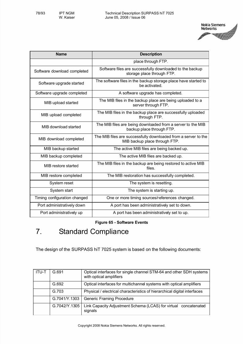
7/27/2019 Surpass Hit 7025 Td
http://slidepdf.com/reader/full/surpass-hit-7025-td 78/93
78/93 IPT NGMW. Kaiser
Technical Description SURPASS hiT 7025June 05, 2008 / Issue 06
Copyright 2008 Nokia Siemens Networks. All rights reserved.
Name Description
place through FTP.
Software download completedSoftware files are successfully downloaded to the backup
storage place through FTP.
Software upgrade startedThe software files in the backup storage place have started to
be activated.
Software upgrade completed A software upgrade has completed.
MIB upload startedThe MIB files in the backup place are being uploaded to a
server through FTP.
MIB upload completedThe MIB files in the backup place are successfully uploaded
through FTP.
MIB download startedThe MIB files are being downloaded from a server to the MIB
backup place through FTP.
MIB download completedThe MIB files are successfully downloaded from a server to the
MIB backup place through FTP.
MIB backup started The active MIB files are being backed up.
MIB backup completed The active MIB files are backed up.
MIB restore startedThe MIB files in the backup are being restored to active MIB
files.
MIB restore completed The MIB restoration has successfully completed.
System reset The system is resetting.
System start The system is starting up.
Timing configuration changed One or more timing sources/references changed.
Port administratively down A port has been administratively set to down.
Port administratively up A port has been administratively set to up.
Figure 65 - Software Events
7. Standard Compliance
The design of the SURPASS hiT 7025 system is based on the following documents:
ITU-T G.691 Optical interfaces for single channel STM-64 and other SDH systemswith optical amplifiers
G.692 Optical interfaces for multichannel systems with optical amplifiers
G.703 Physical / electrical characteristics of hierarchical digital interfaces
G.7041/Y.1303 Generic Framing Procedure
G.7042/Y.1305 Link Capacity Adjustment Schema (LCAS) for virtual concatenatedsignals
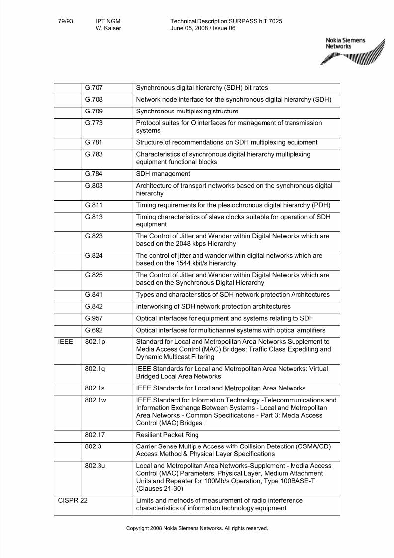
7/27/2019 Surpass Hit 7025 Td
http://slidepdf.com/reader/full/surpass-hit-7025-td 79/93
79/93 IPT NGMW. Kaiser
Technical Description SURPASS hiT 7025June 05, 2008 / Issue 06
Copyright 2008 Nokia Siemens Networks. All rights reserved.
G.707 Synchronous digital hierarchy (SDH) bit rates
G.708 Network node interface for the synchronous digital hierarchy (SDH)
G.709 Synchronous multiplexing structure
G.773 Protocol suites for Q interfaces for management of transmissionsystems
G.781 Structure of recommendations on SDH multiplexing equipment
G.783 Characteristics of synchronous digital hierarchy multiplexingequipment functional blocks
G.784 SDH management
G.803 Architecture of transport networks based on the synchronous digital
hierarchyG.811 Timing requirements for the plesiochronous digital hierarchy (PDH)
G.813 Timing characteristics of slave clocks suitable for operation of SDHequipment
G.823 The Control of Jitter and Wander within Digital Networks which arebased on the 2048 kbps Hierarchy
G.824 The control of jitter and wander within digital networks which arebased on the 1544 kbit/s hierarchy
G.825 The Control of Jitter and Wander within Digital Networks which arebased on the Synchronous Digital Hierarchy
G.841 Types and characteristics of SDH network protection Architectures
G.842 Interworking of SDH network protection architectures
G.957 Optical interfaces for equipment and systems relating to SDH
G.692 Optical interfaces for multichannel systems with optical amplifiers
IEEE 802.1p Standard for Local and Metropolitan Area Networks Supplement toMedia Access Control (MAC) Bridges: Traffic Class Expediting andDynamic Multicast Filtering
802.1q IEEE Standards for Local and Metropolitan Area Networks: VirtualBridged Local Area Networks
802.1s IEEE Standards for Local and Metropolitan Area Networks802.1w IEEE Standard for Information Technology -Telecommunications and
Information Exchange Between Systems - Local and Metropolitan Area Networks - Common Specifications - Part 3: Media AccessControl (MAC) Bridges:
802.17 Resilient Packet Ring
802.3 Carrier Sense Multiple Access with Collision Detection (CSMA/CD) Access Method & Physical Layer Specifications
802.3u Local and Metropolitan Area Networks-Supplement - Media AccessControl (MAC) Parameters, Physical Layer, Medium AttachmentUnits and Repeater for 100Mb/s Operation, Type 100BASE-T
(Clauses 21-30)
CISPR 22 Limits and methods of measurement of radio interferencecharacteristics of information technology equipment

7/27/2019 Surpass Hit 7025 Td
http://slidepdf.com/reader/full/surpass-hit-7025-td 80/93
80/93 IPT NGMW. Kaiser
Technical Description SURPASS hiT 7025June 05, 2008 / Issue 06
Copyright 2008 Nokia Siemens Networks. All rights reserved.
EN 55022 Limits and methods of measurement of radio interference
characteristics of information technology equipment61000-4
ETS 300 019 Climatic conditions
300127 Electromagnetic compatibility and Radio spectrum Matters (ERM);Radiated emission testing of physically large telecommunicationsystems
300 386 Electromagnetic compatibility
China MII Standard YD/T 1146-2001
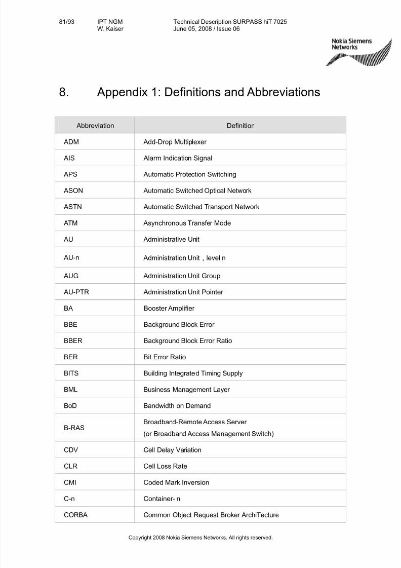
7/27/2019 Surpass Hit 7025 Td
http://slidepdf.com/reader/full/surpass-hit-7025-td 81/93
81/93 IPT NGMW. Kaiser
Technical Description SURPASS hiT 7025June 05, 2008 / Issue 06
Copyright 2008 Nokia Siemens Networks. All rights reserved.
8. Appendix 1: Definitions and Abbreviations
Abbreviation Definition
ADM Add-Drop Multiplexer
AIS Alarm Indication Signal
APS Automatic Protection Switching
ASON Automatic Switched Optical Network
ASTN Automatic Switched Transport Network
ATM Asynchronous Transfer Mode
AU Administrative Unit
AU-n Administration Unit,level n
AUG Administration Unit Group
AU-PTR Administration Unit Pointer
BA Booster Amplifier
BBE Background Block Error
BBER Background Block Error Ratio
BER Bit Error Ratio
BITS Building Integrated Timing Supply
BML Business Management Layer
BoD Bandwidth on Demand
B-RASBroadband-Remote Access Server
(or Broadband Access Management Switch)
CDV Cell Delay Variation
CLR Cell Loss Rate
CMI Coded Mark Inversion
C-n Container- n
CORBA Common Object Request Broker ArchiTecture
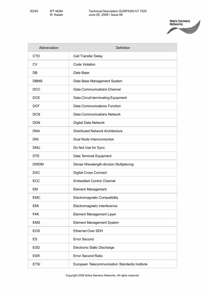
7/27/2019 Surpass Hit 7025 Td
http://slidepdf.com/reader/full/surpass-hit-7025-td 82/93
82/93 IPT NGMW. Kaiser
Technical Description SURPASS hiT 7025June 05, 2008 / Issue 06
Copyright 2008 Nokia Siemens Networks. All rights reserved.
Abbreviation Definition
CTD Cell Transfer Delay
CV Code Violation
DB Data Base
DBMS Data Base Management System
DCC Data Communications Channel
DCE Data Circuit-terminating Equipment
DCF Data Communications Function
DCN Data Communications Network
DDN Digital Data Network
DNA Distributed Network Architecture
DNI Dual Node Interconnection
DNU Do Not Use for Sync.
DTE Data Terminal Equipment
DWDM Dense Wavelength-division Multiplexing
DXC Digital Cross Connect
ECC Embedded Control Channel
EM Element Management
EMC Electromagnetic Compatibility
EMI Electromagnetic Interference
EML Element Management Layer
EMS Element Management System
EOS Ethernet Over SDH
ES Error Second
ESD Electronic Static Discharge
ESR Error Second Ratio
ETSI European Telecommunication Standards Institute

7/27/2019 Surpass Hit 7025 Td
http://slidepdf.com/reader/full/surpass-hit-7025-td 83/93
83/93 IPT NGMW. Kaiser
Technical Description SURPASS hiT 7025June 05, 2008 / Issue 06
Copyright 2008 Nokia Siemens Networks. All rights reserved.
Abbreviation Definition
FDM Frequency Division Multiplexing
FDDI Fiber Distributed Data Interface
FEBBE Far End Background Block Error
FEES Far End Errored Second
FESES Far End Severely Errored Second
GMPLS Generalized Multi-Protocol Label Switching
GUI Graphical User Interface
HDLC High Digital Link Control
HPC Higher order Path Connection
IP Internet Protocol
ITU-TInternational Telecommunication Union-TelecommunicationStandardization Sector
L2 Layer 2
LAN Local Area Network
LAPD Link Access Procedure On D-channel
LCT Local Craft Terminal
LMS Local NE Management System
LOF Loss Of Frame
LOM Loss of Multi-Frame
LOP Loss Of Pointer
LOS Loss Of Signal
LPC Lower order Path Connection
MAC Medium Access Control
MAN Metropolitan Area Network
MCU Micro Control Unit
MDI Miscellaneous Discrete Input
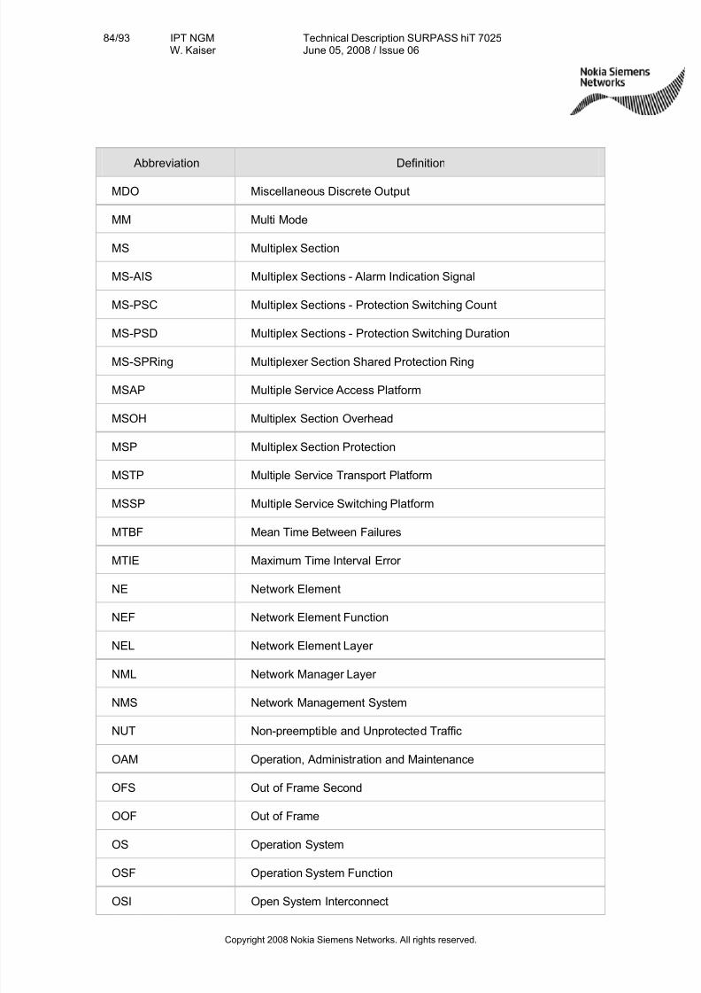
7/27/2019 Surpass Hit 7025 Td
http://slidepdf.com/reader/full/surpass-hit-7025-td 84/93
84/93 IPT NGMW. Kaiser
Technical Description SURPASS hiT 7025June 05, 2008 / Issue 06
Copyright 2008 Nokia Siemens Networks. All rights reserved.
Abbreviation Definition
MDO Miscellaneous Discrete Output
MM Multi Mode
MS Multiplex Section
MS-AIS Multiplex Sections - Alarm Indication Signal
MS-PSC Multiplex Sections - Protection Switching Count
MS-PSD Multiplex Sections - Protection Switching Duration
MS-SPRing Multiplexer Section Shared Protection Ring
MSAP Multiple Service Access Platform
MSOH Multiplex Section Overhead
MSP Multiplex Section Protection
MSTP Multiple Service Transport Platform
MSSP Multiple Service Switching Platform
MTBF Mean Time Between Failures
MTIE Maximum Time Interval Error
NE Network Element
NEF Network Element Function
NEL Network Element Layer
NML Network Manager Layer
NMS Network Management System
NUT Non-preemptible and Unprotected Traffic
OAM Operation, Administration and Maintenance
OFS Out of Frame Second
OOF Out of Frame
OS Operation System
OSF Operation System Function
OSI Open System Interconnect
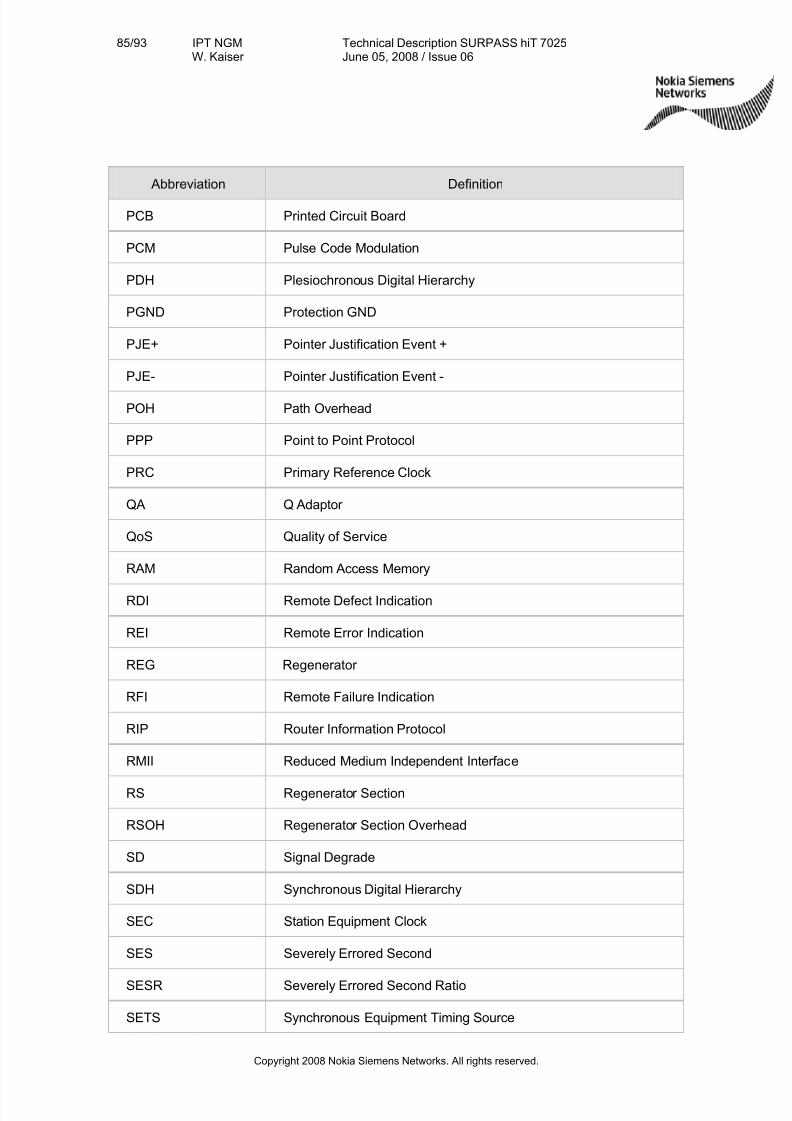
7/27/2019 Surpass Hit 7025 Td
http://slidepdf.com/reader/full/surpass-hit-7025-td 85/93
85/93 IPT NGMW. Kaiser
Technical Description SURPASS hiT 7025June 05, 2008 / Issue 06
Copyright 2008 Nokia Siemens Networks. All rights reserved.
Abbreviation Definition
PCB Printed Circuit Board
PCM Pulse Code Modulation
PDH Plesiochronous Digital Hierarchy
PGND Protection GND
PJE+ Pointer Justification Event +
PJE- Pointer Justification Event -
POH Path Overhead
PPP Point to Point Protocol
PRC Primary Reference Clock
QA Q Adaptor
QoS Quality of Service
RAM Random Access Memory
RDI Remote Defect Indication
REI Remote Error Indication
REG Regenerator
RFI Remote Failure Indication
RIP Router Information Protocol
RMII Reduced Medium Independent Interface
RS Regenerator Section
RSOH Regenerator Section Overhead
SD Signal Degrade
SDH Synchronous Digital Hierarchy
SEC Station Equipment Clock
SES Severely Errored Second
SESR Severely Errored Second Ratio
SETS Synchronous Equipment Timing Source
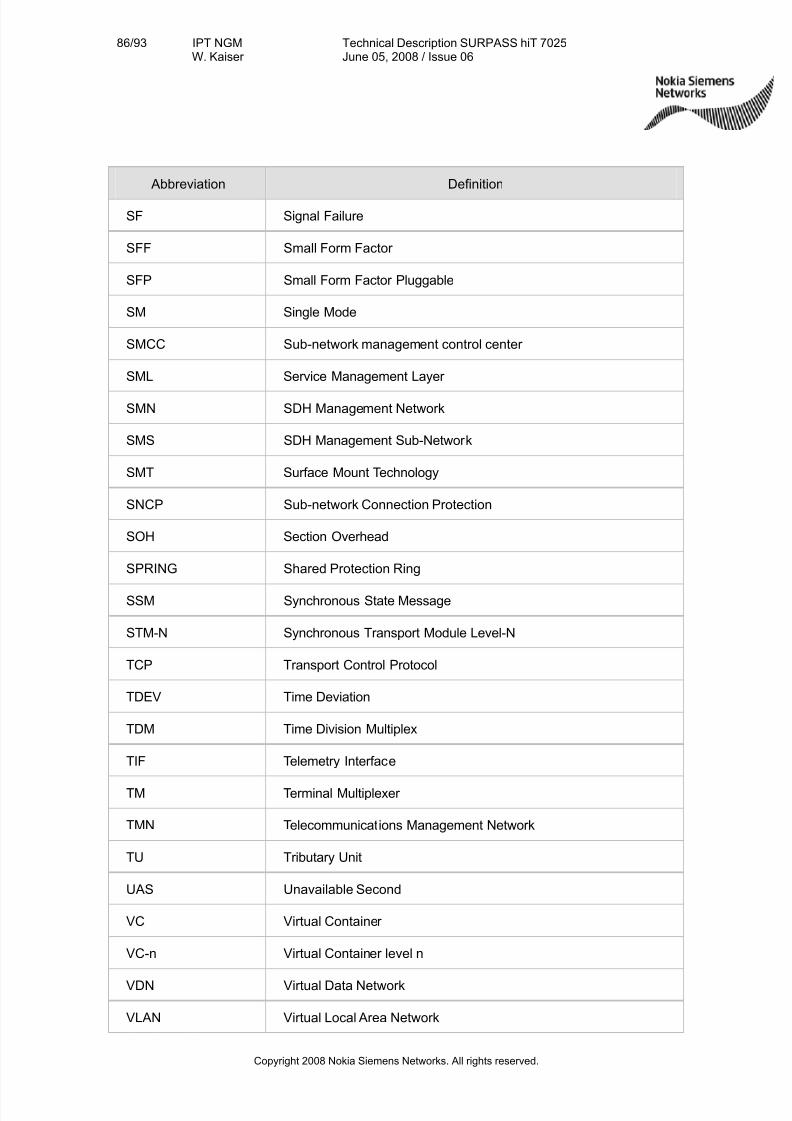
7/27/2019 Surpass Hit 7025 Td
http://slidepdf.com/reader/full/surpass-hit-7025-td 86/93
86/93 IPT NGMW. Kaiser
Technical Description SURPASS hiT 7025June 05, 2008 / Issue 06
Copyright 2008 Nokia Siemens Networks. All rights reserved.
Abbreviation Definition
SF Signal Failure
SFF Small Form Factor
SFP Small Form Factor Pluggable
SM Single Mode
SMCC Sub-network management control center
SML Service Management Layer
SMN SDH Management Network
SMS SDH Management Sub-Network
SMT Surface Mount Technology
SNCP Sub-network Connection Protection
SOH Section Overhead
SPRING Shared Protection Ring
SSM Synchronous State Message
STM-N Synchronous Transport Module Level-N
TCP Transport Control Protocol
TDEV Time Deviation
TDM Time Division Multiplex
TIF Telemetry Interface
TM Terminal Multiplexer
TMN Telecommunications Management Network
TU Tributary Unit
UAS Unavailable Second
VC Virtual Container
VC-n Virtual Container level n
VDN Virtual Data Network
VLAN Virtual Local Area Network

7/27/2019 Surpass Hit 7025 Td
http://slidepdf.com/reader/full/surpass-hit-7025-td 87/93
87/93 IPT NGMW. Kaiser
Technical Description SURPASS hiT 7025June 05, 2008 / Issue 06
Copyright 2008 Nokia Siemens Networks. All rights reserved.
Abbreviation Definition
WAN Wide Area Network
WDM Wavelength Division Multiplexing
7/27/2019 Surpass Hit 7025 Td
http://slidepdf.com/reader/full/surpass-hit-7025-td 88/93
88/93 IPT NGMW. Kaiser
Technical Description SURPASS hiT 7025June 05, 2008 / Issue 06
Copyright 2008 Nokia Siemens Networks. All rights reserved.
9. Appendix 2: Basis Technologies
In this section, the following key basis technologies for SURPASS hiT 70series aredescribed:
Generic Framing Procedure (GFP)
Virtual Concatenation (VCat, a standard way of packing lower bandwidth circuits intoSDH/SONET frames)
Link Capacity Adjustment Scheme (LCAS)
Ethernet Functions
RPR (Resilient Packet Ring)
9.1 Generic Framing Procedure (GFP)
GFP/G.7041 provides a framing procedure for octet-aligned, variable-length payloadsfor subsequent mapping into SDH VC-groups.
GFP differs from other packet mappings (e.g., Packet over SONET) because it is Layer 2 independent and maintains the Layer-2 header information, in a manner such thatthe destination node may reproduce the entire stream of Layer-2 frames. This in turn,allows the transport network to transparently connect two Layer-2 devices.
GFP standard includes two modes: transparent and frame-mapped.
Transparent Mode (GFP-T) allows block-coded LAN and SAN signals, such asGigabit Ethernet, Fiber Channel, Ficon, and Escon, to be transported and switchedacross an optical network, while preserving the full client-signal information
Frame-Mapped Mode (GFP-F), on the other hand, is used to adapt Protocol Data Unit(PDU)-oriented signals – client signals that are already framed or packetized by theclient protocol – and may operate at the data-link layer (or higher) of the client signal.GFP-F maps one frame or packet of the client signal, such as IP/PPP or EthernetMAC, into one GFP frame. GFP frames, each associated with different clients, can be
multiplexed onto a single TDM channel before SDH transport. This packet aggregationcapability provides greater bandwidth efficiency.
SURPASS hiT 7025 supports the GFP-F mode. The FCS of the GFP frame mayoptionally be used, additionally to the FCS of the Ethernet frame.

7/27/2019 Surpass Hit 7025 Td
http://slidepdf.com/reader/full/surpass-hit-7025-td 89/93
89/93 IPT NGMW. Kaiser
Technical Description SURPASS hiT 7025June 05, 2008 / Issue 06
Copyright 2008 Nokia Siemens Networks. All rights reserved.
VC
Overhead VC Payload
GFP Frame
Preamble SFD control0x11 DA 6-bytes SA 6-bytes T/L 2-bytes Payload CRC 4-bytesEthernet Packet
PLI 2 -bytes HEC 2 byte type 2-bytes HEC 2byte GFP Ex Payload FCS 4-bytes
Core Header Payload Header
Variable 4-65535Byte
GFPFrame
SDHFrame
Figure 66 - GFP mapping
Benefits of GFP
The key benefits of GFP are the uniform mechanism to support all L2 protocols andhigh encapsulation efficiency. This provides convergence of next-generation serviceswith existing infrastructure investment to provide network consolidation and costsavings. GFP provides:
•Uniform and deterministic mapping of packet and future services to SDH/SONETtransport protocols which is more robust frame delineation than flag-basedmechanisms such as HDLC.
•Efficient network resource utilization via GFP’s low overhead characteristics, andcompatibility with virtual-concatenation processing
• Flexibility of Extension Headers: This allows topology application specific fields tobe defined without affecting frame delineation functions
•Payload independent frame expansion, and therefore no byte stuffing.
•Greater bandwidth efficiency through GFP-F frame-mode’s support for packet-level multiplexing, which allows aggregation of multiple client streams into a singleTDM channel
• The ability to identify the encapsulated client protocol separately from theExtension Header. This could be used to allow frame forwarding based on
Extension Header fields without requiring recognition of the encapsulated clientprotocol.
•GFP provides the interworking condition among different vendors, which is not soeasy to obtain with other alternatives of the Ethernet over SDH, like PPP. Thefollowing table provides with a comparison between the two methods.
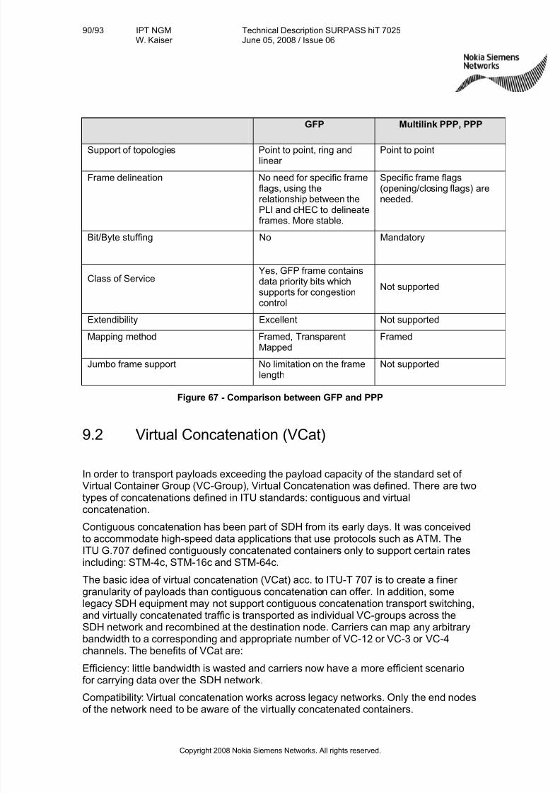
7/27/2019 Surpass Hit 7025 Td
http://slidepdf.com/reader/full/surpass-hit-7025-td 90/93
90/93 IPT NGMW. Kaiser
Technical Description SURPASS hiT 7025June 05, 2008 / Issue 06
Copyright 2008 Nokia Siemens Networks. All rights reserved.
GFP Multilink PPP, PPP
Support of topologies Point to point, ring andlinear
Point to point
Frame delineation No need for specific frameflags, using therelationship between thePLI and cHEC to delineateframes. More stable.
Specific frame flags(opening/closing flags) areneeded.
Bit/Byte stuffing No Mandatory
Class of ServiceYes, GFP frame containsdata priority bits whichsupports for congestioncontrol
Not supported
Extendibility Excellent Not supported
Mapping method Framed, TransparentMapped
Framed
Jumbo frame support No limitation on the framelength
Not supported
Figure 67 - Comparison between GFP and PPP
9.2 Virtual Concatenation (VCat)
In order to transport payloads exceeding the payload capacity of the standard set of Virtual Container Group (VC-Group), Virtual Concatenation was defined. There are twotypes of concatenations defined in ITU standards: contiguous and virtualconcatenation.
Contiguous concatenation has been part of SDH from its early days. It was conceivedto accommodate high-speed data applications that use protocols such as ATM. The
ITU G.707 defined contiguously concatenated containers only to support certain ratesincluding: STM-4c, STM-16c and STM-64c.
The basic idea of virtual concatenation (VCat) acc. to ITU-T 707 is to create a finer granularity of payloads than contiguous concatenation can offer. In addition, somelegacy SDH equipment may not support contiguous concatenation transport switching,and virtually concatenated traffic is transported as individual VC-groups across theSDH network and recombined at the destination node. Carriers can map any arbitrarybandwidth to a corresponding and appropriate number of VC-12 or VC-3 or VC-4channels. The benefits of VCat are:
Efficiency: little bandwidth is wasted and carriers now have a more efficient scenariofor carrying data over the SDH network.
Compatibility: Virtual concatenation works across legacy networks. Only the end nodesof the network need to be aware of the virtually concatenated containers.

7/27/2019 Surpass Hit 7025 Td
http://slidepdf.com/reader/full/surpass-hit-7025-td 91/93
91/93 IPT NGMW. Kaiser
Technical Description SURPASS hiT 7025June 05, 2008 / Issue 06
Copyright 2008 Nokia Siemens Networks. All rights reserved.
Intermediate SDH nodes forward the single Containers transparently throughout the
network. Hence, with virtual concatenation, such channels can be routed over legacynetworks that do not support contiguous channels.
Reliability: Virtual Concatenation, along with LCAS, allows new and efficient sharedprotection mechanism.
9.3 Link Capacity Adjustment Scheme (LCAS)
LCAS (ITU-T Recommendation G.7042/Y.1305, approved by the ITU-T in November 2001) is a protocol to synchronize the re-sizing of a virtual concatenation group in use,
so it can be changed without corrupting packets in the process. LCAS providesautomatic recovery of a link after member failures.
LCAS builds on Virtual Concatenation. While the virtual concatenation is a simplelabeling of individual VC members within a virtual concatenation group, LCAS is a two-way signaling protocol that runs continuously between the two ends of the pipe andensures that commands from the network management system to alter the pipecapacity do not impair the user’s traffic. LCAS adds several highly significant featuresto SDH’s capabilities:
• The combination of VCat and LCAS creates fine-tuned and variable capacity SDHpipes to match the needs of packet data QOS (quality of service) and customer SLAs (service-level agreements) – and to boost carriers’ traffic-handling scalability
and efficiency. LCAS allows adjustment of the size of a virtually concatenatedgroup of channels.
• The combination of VCat and LCAS can also provide soft protection schemes.Using VCat, traffic is distributively mapped into several SDH containers (e.g. VC-12s) and sent by different paths. When certain VC-12s in the same VC group fail,LCAS can delete the failed VCs from the group. The traffic can then bedynamically adapted to the rest of the VC12s bandwidth for transmission.Otherwise – without LCAS - a failure in one path of a channel built up of diverselyrouted paths would lead to loss of all the traffic.
•
9.4 Ethernet Functions and Services
Layer 2 Ethernet functions implemented in state-of-the-art transport system mayinclude the following:
• Layer 2 aggregation
• Layer 2 switching
• 802.1p QoS/CoS based on Ethernet port and/or VLAN
•Rapid Spanning Tree Protocol (RSTP) to provide Layer 2 traffic protection
•Rate limiting function per port and policing per Port or per VLAN basis, themaximum allowable rate per port or per VLAN is user provisionable.
7/27/2019 Surpass Hit 7025 Td
http://slidepdf.com/reader/full/surpass-hit-7025-td 92/93
92/93 IPT NGMW. Kaiser
Technical Description SURPASS hiT 7025June 05, 2008 / Issue 06
Copyright 2008 Nokia Siemens Networks. All rights reserved.
•VLAN function
•Ethernet Shared Ring (ESR): Layer 2 switch and Aggregator cards: all the trafficgoes through the shared ring.
•Ethernet / (virtual) Private Line / Ethernet Private-Line (EpL)
•Ethernet (virtual) LAN (EvLAN) / Ethernet-LAN (ELAN)
7/27/2019 Surpass Hit 7025 Td
http://slidepdf.com/reader/full/surpass-hit-7025-td 93/93
93/93 IPT NGMW. Kaiser
Technical Description SURPASS hiT 7025June 05, 2008 / Issue 06
10. Appendix 3: Related Documents
• Technical Description SURPASS hiT 7020
• Technical Description SURPASS hiT 7030
• Technical Description SURPASS hiT 7035
• Technical Description SURPASS hiT 7050
• Technical Description SURPASS hiT 7060
• Technical Description SURPASS hiT 7060 HC
• Technical Description SURPASS hiT 7070 SC/DC
• Technical Description SURPASS hiT 7080