Embed Size (px)
Citation preview

As described by:
Jorge L. Orbay, M.D.
Miami Hand & Upper Extremity Institute
Miami, Florida.
SURGICAL TECHNIQUE GUIDE

1
2 DISTAL ULNA LANDMARKS
ELBOW LANDMARKS
To identify the axis of forearm rotation, pronate the hand and flex the wrist.
Palpate and mark the ulnar styloid, ulnar head and the direction of the shaft.
Note: Use fluoroscopic imaging to verify proper landmark placement.
With the elbow flexed 900,
palpate and mark the lateral epicondyle.
Make an 8 -10cm line through the marked point.
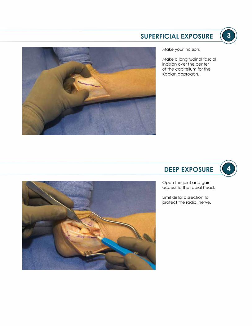
SUPERFICIAL EXPOSURE
DEEP EXPOSURE
3
4
Make your incision.
Make a longitudinal fascial incision over the center of the capitellum for the Kaplan approach.
Open the joint and gain access to the radial head.
Limit distal dissection to protect the radial nerve.

5
6
HEAD SIZING
Remove the radial head fragments; assemble and measure them using the Radial Head Sizing Tray.
Note: If between radial head sizes, select the smaller.
TRIAL HEAD SELECTION
Select the Trial Head that corresponds to the native head.
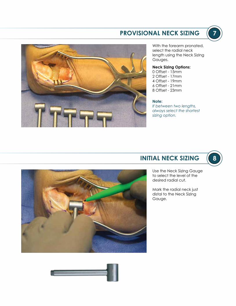
7
8
PROVISIONAL NECK SIZING
INITIAL NECK SIZING
With the forearm pronated, select the radial neck length using the Neck Sizing Gauges.
Note: If between two lengths, always select the shortest sizing option.
Use the Neck Sizing Gauge to select the level of the desired radial cut.
Mark the radial neck just distal to the Neck Sizing Gauge.
Neck Sizing Options:0 Offset - 15mm2 Offset - 17mm4 Offset - 19mm6 Offset - 21mm8 Offset - 23mm

9
10 RESECTION
ATTACHING BONE FORCEPS
Lift the radius with the Bone Holding Forceps, then make the radial neck cut.
CAUTION: Protect the radial nerve.
Note: The maximum defect that can be corrected is 23mm.
Secure the Bone Holding Forceps just distal to the marked radial neck.

11
12
OPENING RADIAL CANAL
CANAL PREPARATION
Starting with the smallest Rasp, position the hand in pronation and insert the Rasp past the tuberosity in the direction of the radial styloid.
Note: This will establish the trajectory for all subsequent Rasps.
Insert each of the Rasps up to the etched depth mark.
Continue broaching until cortical bone is encountered.
Note:Each Rasp should be used as a broach. If the final Rasp used does not fully seat to the depth mark, a twisting motion can be used to ream.
Note the size of the final Rasp used.
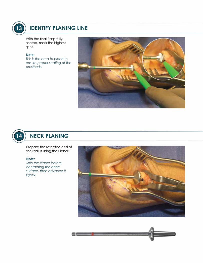
13
14 NECK PLANING
IDENTIFY PLANING LINE
With the final Rasp fully seated, mark the highest spot.
Note: This is the area to plane to ensure proper seating of the prosthesis.
Prepare the resected end of the radius using the Planer.
Note:Spin the Planer before contacting the bone surface, then advance it lightly.
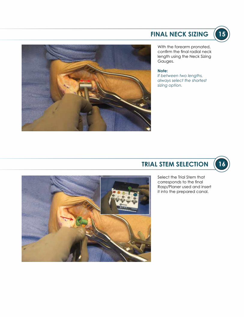
15
16
FINAL NECK SIZING
TRIAL STEM SELECTION
With the forearm pronated, confirm the final radial neck length using the Neck Sizing Gauges.
Note: If between two lengths, always select the shortest sizing option.
Select the Trial Stem that corresponds to the final Rasp/Planer used and insert it into the prepared canal.
17
18
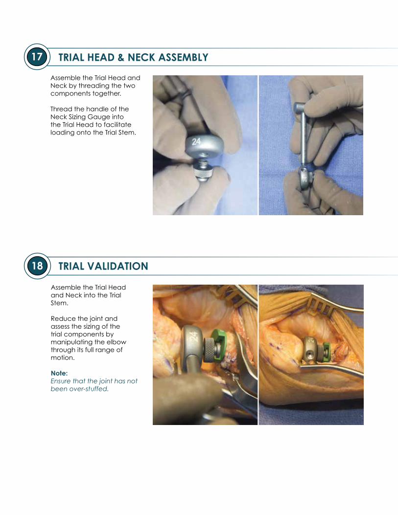
TRIAL HEAD & NECK ASSEMBLY
TRIAL VALIDATION
Assemble the Trial Head and Neck by threading the two components together.
Thread the handle of the Neck Sizing Gauge into the Trial Head to facilitate loading onto the Trial Stem.
Assemble the Trial Head and Neck into the Trial Stem.
Reduce the joint and assess the sizing of the trial components by manipulating the elbow through its full range of motion.
Note:Ensure that the joint has not been over-stuffed.
19
20
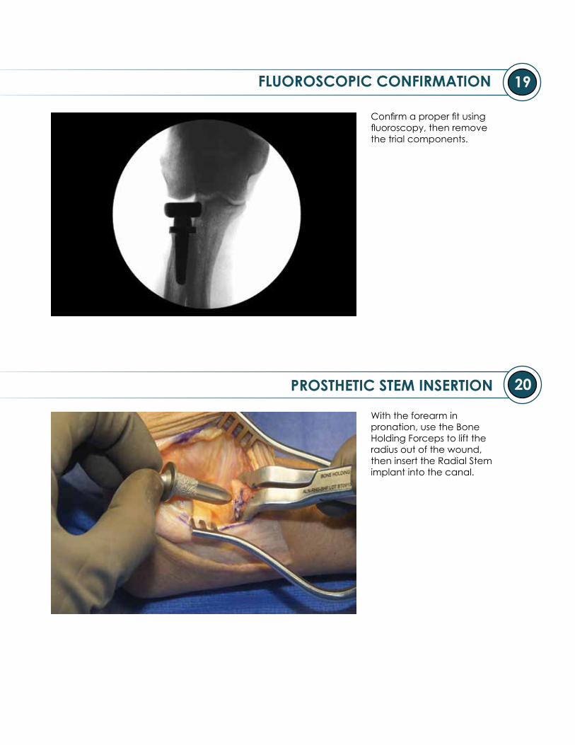
FLUOROSCOPIC CONFIRMATION
Confirm a proper fit using fluoroscopy, then remove the trial components.
PROSTHETIC STEM INSERTION
With the forearm in pronation, use the Bone Holding Forceps to lift the radius out of the wound, then insert the Radial Stem implant into the canal.

21
22 PROSTHETIC HEAD LOADING
PROSTHETIC STEM IMPACTOR
Side load the Radial Head implant onto the stem, then rotate it until the threads are positioned laterally.
Note: Each Radial Head implant is packaged with its respective Lock Screw.
Insert the Stem Impactor laterally, then lower the handle until in-line with the stem.
Impact the stem until the collar seats flush against the radius.
Note: The notch on the Stem Impactor facilitates loading.
23
24
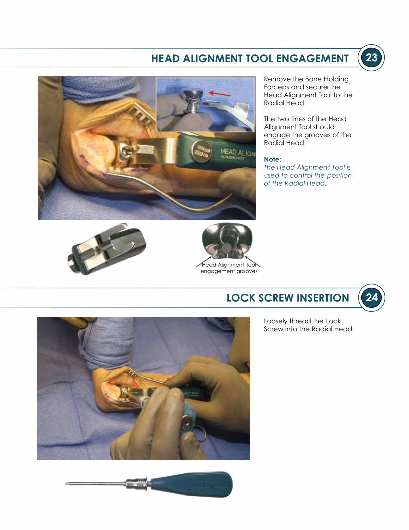
HEAD ALIGNMENT TOOL ENGAGEMENT
Remove the Bone Holding Forceps and secure the Head Alignment Tool to the Radial Head.
The two tines of the Head Alignment Tool should engage the grooves of the Radial Head.
Note: The Head Alignment Tool is used to control the position of the Radial Head.
Head Alignment Toolengagement grooves
LOCK SCREW INSERTION
Loosely thread the Lock Screw into the Radial Head.
25
26
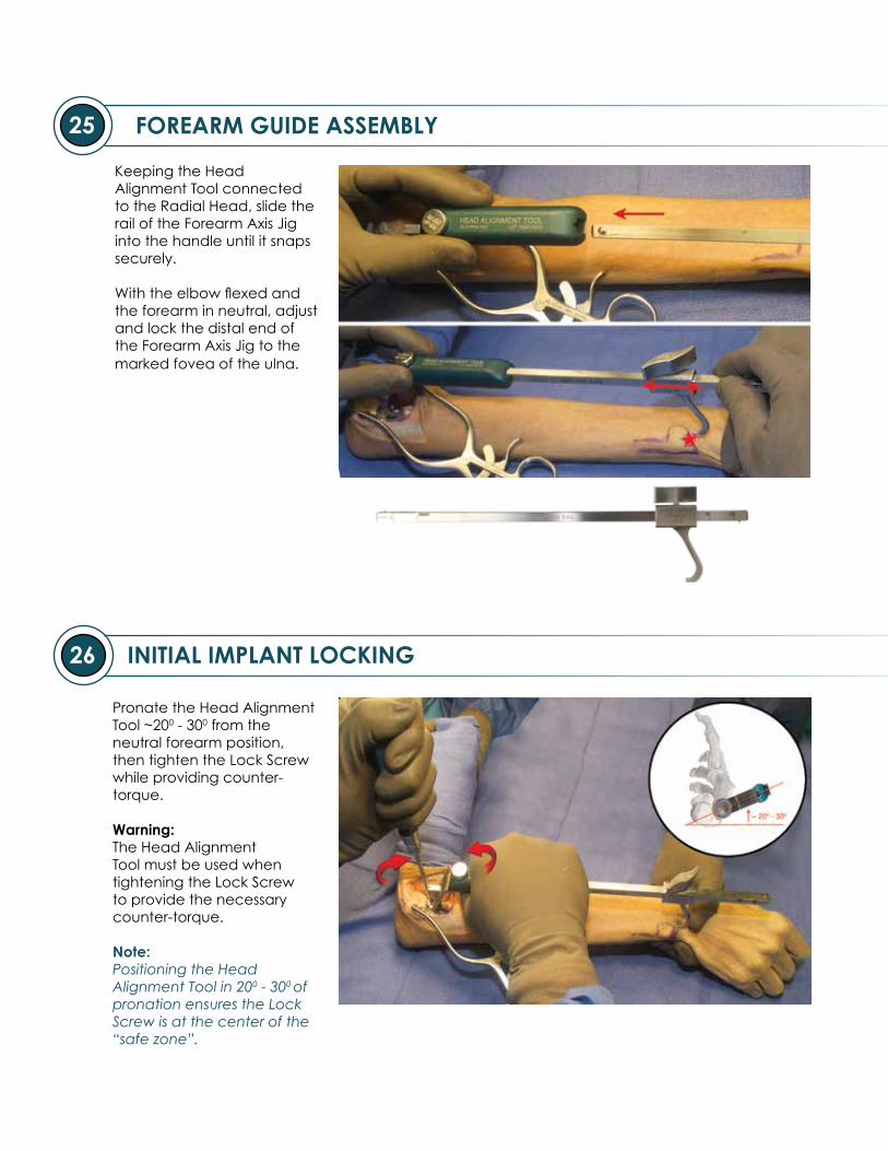
FOREARM GUIDE ASSEMBLY
INITIAL IMPLANT LOCKING
Keeping the Head Alignment Tool connected to the Radial Head, slide the rail of the Forearm Axis Jig into the handle until it snaps securely.
With the elbow flexed and the forearm in neutral, adjust and lock the distal end of the Forearm Axis Jig to the marked fovea of the ulna.
Pronate the Head Alignment Tool ~200 - 300 from the neutral forearm position,
then tighten the Lock Screw while providing counter-torque.
Warning: The Head Alignment Tool must be used when tightening the Lock Screw to provide the necessary counter-torque.
Note: Positioning the Head Alignment Tool in 200 - 300 of pronation ensures the Lock Screw is at the center of the “safe zone”.
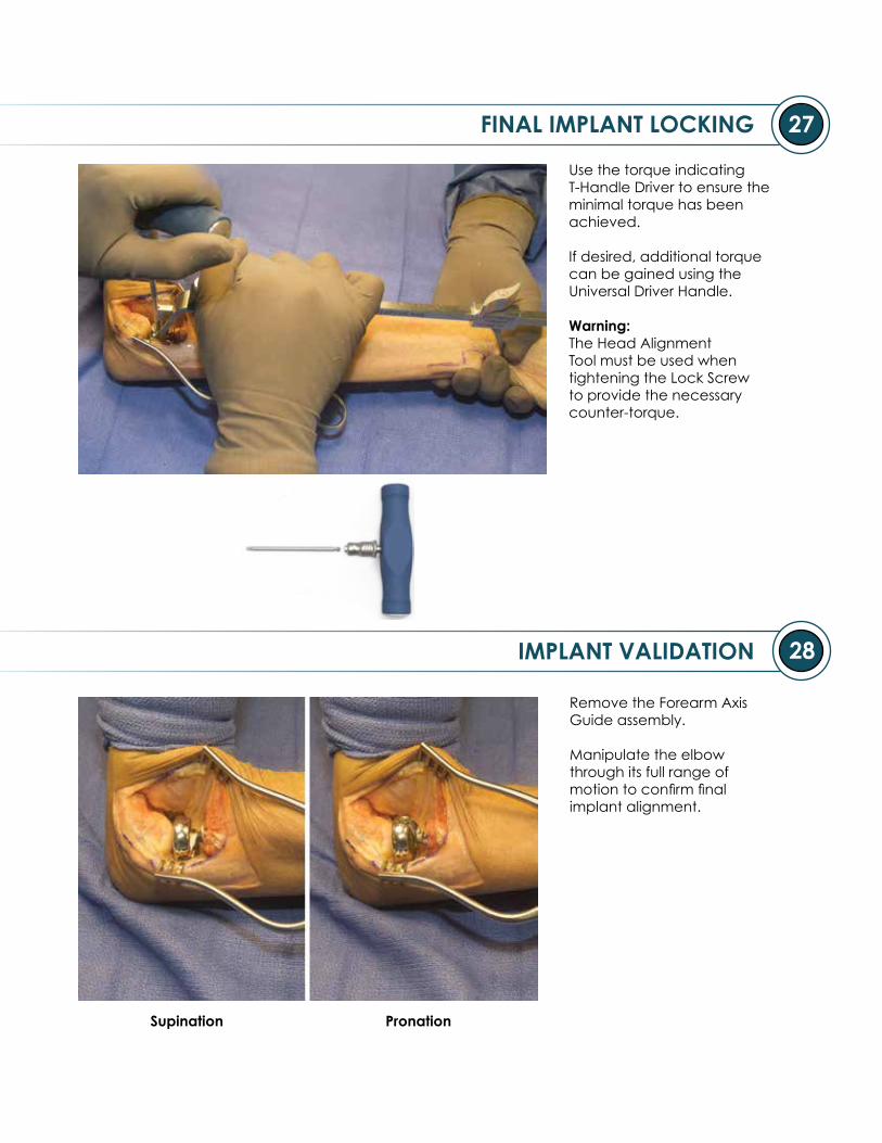
27
28IMPLANT VALIDATION
Supination Pronation
FINAL IMPLANT LOCKING
Use the torque indicating T-Handle Driver to ensure the minimal torque has been achieved.
If desired, additional torque can be gained using the Universal Driver Handle.
Warning: The Head Alignment Tool must be used when tightening the Lock Screw to provide the necessary counter-torque.
Remove the Forearm Axis Guide assembly.
Manipulate the elbow through its full range of motion to confirm final implant alignment.
29
30
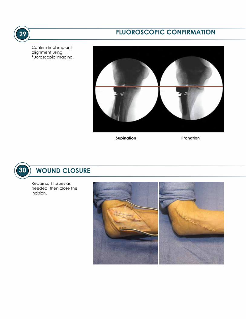
FLUOROSCOPIC CONFIRMATION
WOUND CLOSURE
Supination Pronation
Confirm final implant alignment using fluoroscopic imaging.
Repair soft tissues as needed, then close the incision.
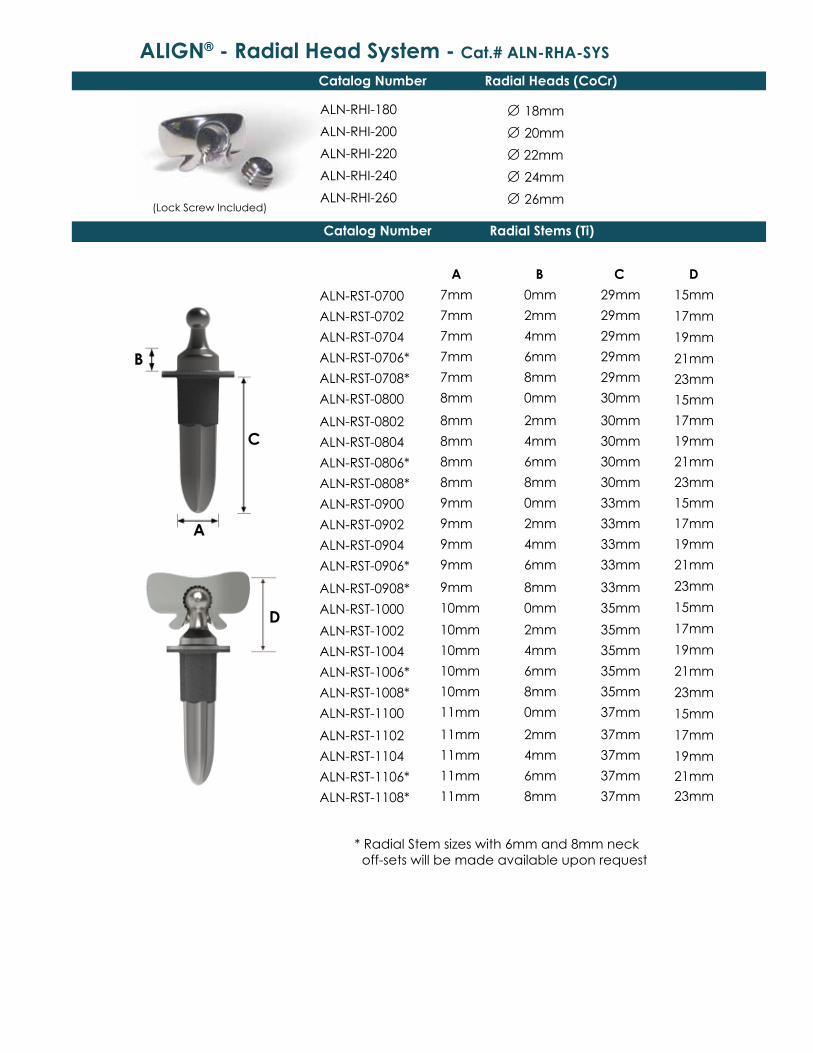
ALIGN® - Radial Head System - Cat.# ALN-RHA-SYS
(Lock Screw Included)
A B C
7mm 0mm 29mm
7mm 2mm 29mm
7mm 4mm 29mm
7mm 6mm 29mm
7mm 8mm 29mm
8mm 0mm 30mm
8mm 2mm 30mm
8mm 4mm 30mm
8mm 6mm 30mm
8mm 8mm 30mm
9mm 0mm 33mm
9mm 2mm 33mm
9mm 4mm 33mm
9mm 6mm 33mm
9mm 8mm 33mm
10mm 0mm 35mm
10mm 2mm 35mm
10mm 4mm 35mm
10mm 6mm 35mm
10mm 8mm 35mm
11mm 0mm 37mm
11mm 2mm 37mm
11mm 4mm 37mm
11mm 6mm 37mm
11mm 8mm 37mm
ALN-RHI-180 ∅ 18mm
ALN-RHI-200 ∅ 20mm
ALN-RHI-220 ∅ 22mm
ALN-RHI-240 ∅ 24mm
ALN-RHI-260 ∅ 26mm
B
A
C
Catalog Number Radial Heads (CoCr)
Catalog Number Radial Stems (Ti)
ALN-RST-0700
ALN-RST-0702
ALN-RST-0704
ALN-RST-0706*
ALN-RST-0708*
ALN-RST-0800
ALN-RST-0802
ALN-RST-0804
ALN-RST-0806*
ALN-RST-0808*
ALN-RST-0900
ALN-RST-0902
ALN-RST-0904
ALN-RST-0906*
ALN-RST-0908*
ALN-RST-1000
ALN-RST-1002
ALN-RST-1004
ALN-RST-1006*
ALN-RST-1008*
ALN-RST-1100
ALN-RST-1102
ALN-RST-1104
ALN-RST-1106*
ALN-RST-1108*
D
15mm
17mm
19mm
21mm
23mm
15mm
17mm
19mm
21mm
23mm
15mm
17mm
19mm
21mm
23mm
15mm
17mm
19mm
21mm
23mm
15mm
17mm
19mm
21mm
23mm
D
* Radial Stem sizes with 6mm and 8mm neck off-sets will be made available upon request

Notes

Notes
8905 SW 87th Avenue, Miami, Florida 33176 Tele: 877 753 5396
© 2016 Skeletal Dynamics, LLC
MKT-00003-00RAG
April 2016
Emergo Europe, Molenstraat 15, 2513 BH
The Hague, The Netherlands
R E D U C Theadless compression screw
TM
P R O T E A Nr a d i a l h e a d p l a t e
TM
IJS-ELBOWelbow stabil ization system
TM


