Embed Size (px)
Citation preview

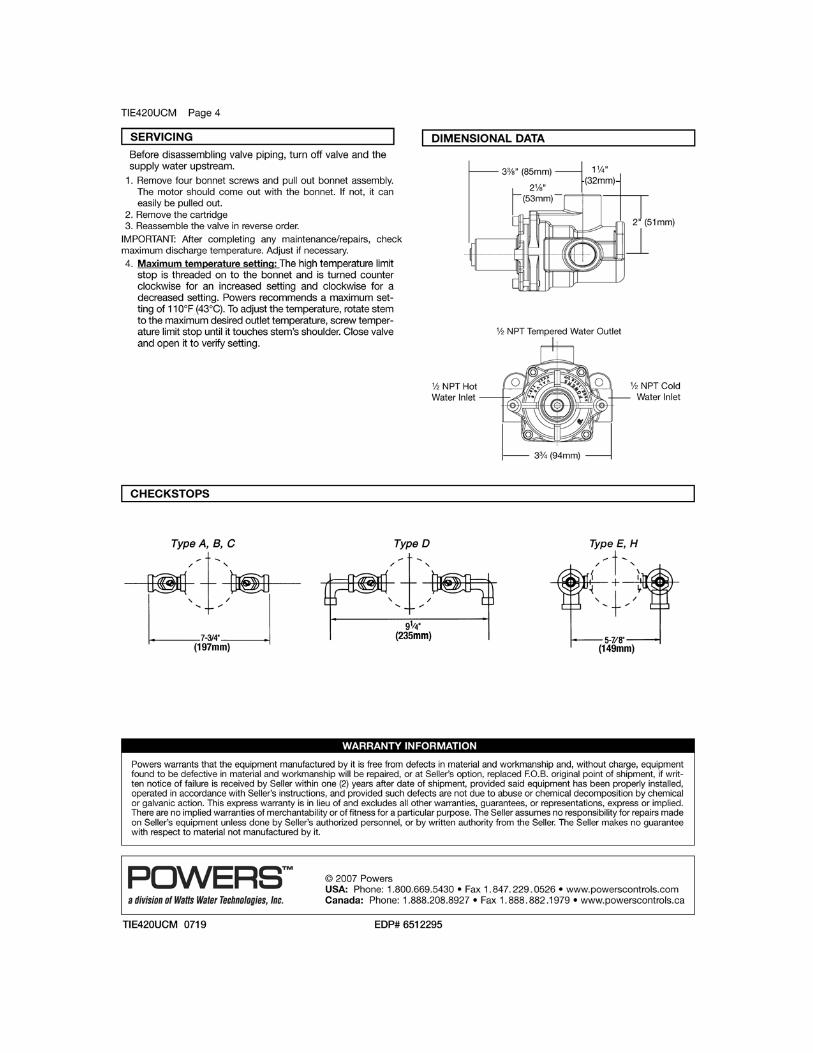
SURGICAL SCRUB SINKS
INSTALLATION – OPERATION – MAINTENANCE
USER MANUAL
Mac Medical, Inc.
820 South Mulberry Street
Millstadt, Illinois 62260
(618) 476‐3550 phone
(618) 476‐3337 fax
July, 2014
California OSHPD
Pre-approved
MAN-004 REV. C
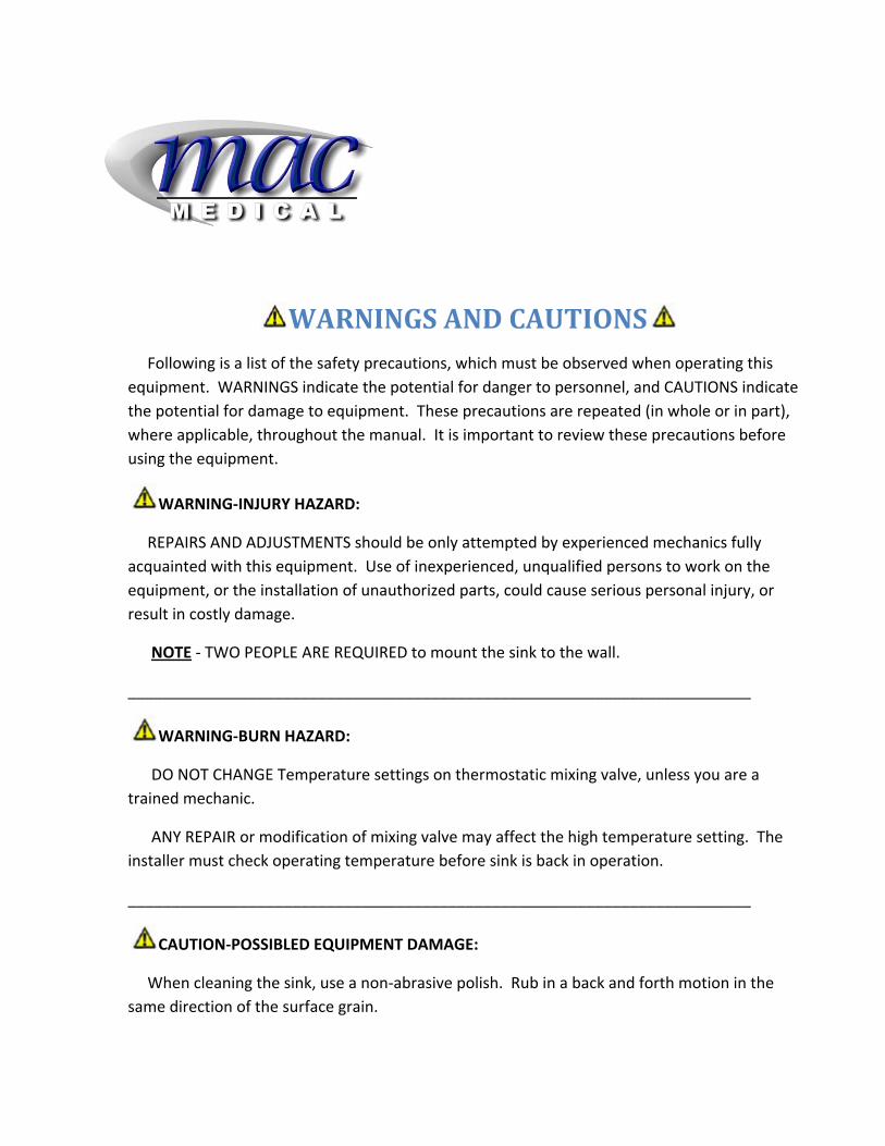
WARNINGSANDCAUTIONS Following is a list of the safety precautions, which must be observed when operating this
equipment. WARNINGS indicate the potential for danger to personnel, and CAUTIONS indicate
the potential for damage to equipment. These precautions are repeated (in whole or in part),
where applicable, throughout the manual. It is important to review these precautions before
using the equipment.
WARNING‐INJURY HAZARD:
REPAIRS AND ADJUSTMENTS should be only attempted by experienced mechanics fully
acquainted with this equipment. Use of inexperienced, unqualified persons to work on the
equipment, or the installation of unauthorized parts, could cause serious personal injury, or
result in costly damage.
NOTE ‐ TWO PEOPLE ARE REQUIRED to mount the sink to the wall.
________________________________________________________________________
WARNING‐BURN HAZARD:
DO NOT CHANGE Temperature settings on thermostatic mixing valve, unless you are a
trained mechanic.
ANY REPAIR or modification of mixing valve may affect the high temperature setting. The
installer must check operating temperature before sink is back in operation.
________________________________________________________________________
CAUTION‐POSSIBLED EQUIPMENT DAMAGE:
When cleaning the sink, use a non‐abrasive polish. Rub in a back and forth motion in the
same direction of the surface grain.
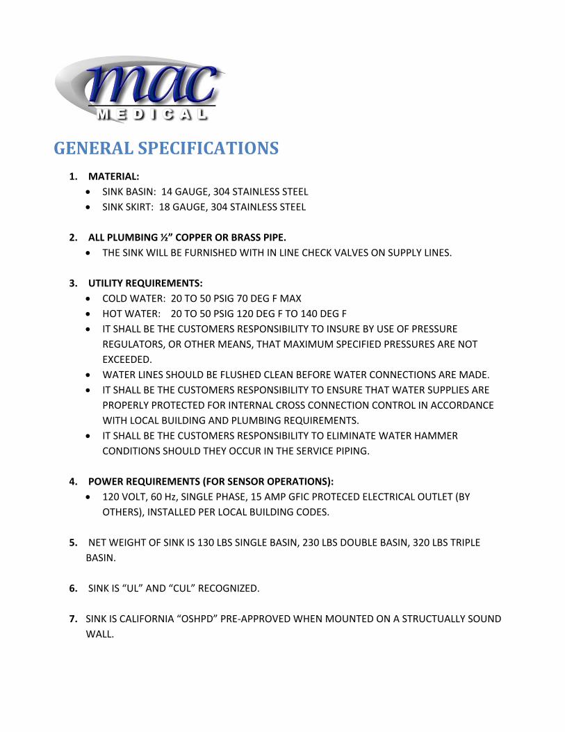
GENERALSPECIFICATIONS1. MATERIAL:
SINK BASIN: 14 GAUGE, 304 STAINLESS STEEL
SINK SKIRT: 18 GAUGE, 304 STAINLESS STEEL
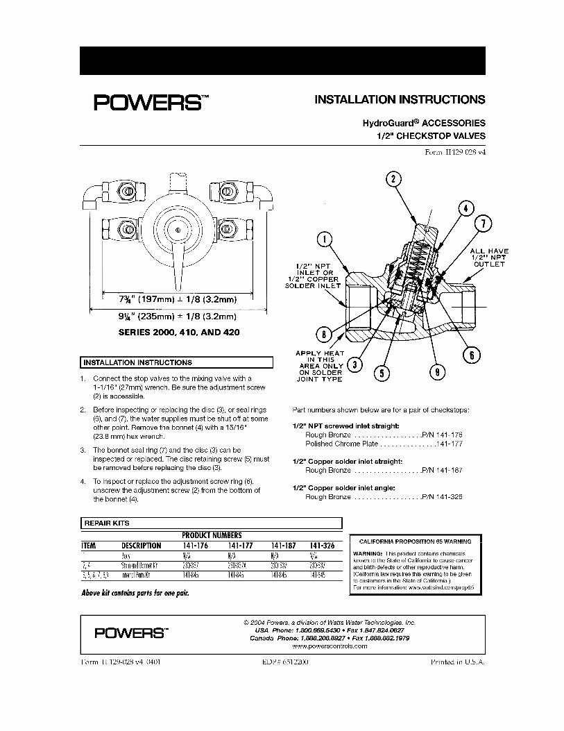
2. ALL PLUMBING ½” COPPER OR BRASS PIPE.
THE SINK WILL BE FURNISHED WITH IN LINE CHECK VALVES ON SUPPLY LINES.
3. UTILITY REQUIREMENTS:
COLD WATER: 20 TO 50 PSIG 70 DEG F MAX
HOT WATER: 20 TO 50 PSIG 120 DEG F TO 140 DEG F IT SHALL BE THE CUSTOMERS RESPONSIBILITY TO INSURE BY USE OF PRESSURE
REGULATORS, OR OTHER MEANS, THAT MAXIMUM SPECIFIED PRESSURES ARE NOT
EXCEEDED.
WATER LINES SHOULD BE FLUSHED CLEAN BEFORE WATER CONNECTIONS ARE MADE. IT SHALL BE THE CUSTOMERS RESPONSIBILITY TO ENSURE THAT WATER SUPPLIES ARE
PROPERLY PROTECTED FOR INTERNAL CROSS CONNECTION CONTROL IN ACCORDANCE
WITH LOCAL BUILDING AND PLUMBING REQUIREMENTS.
IT SHALL BE THE CUSTOMERS RESPONSIBILITY TO ELIMINATE WATER HAMMER
CONDITIONS SHOULD THEY OCCUR IN THE SERVICE PIPING.
4. POWER REQUIREMENTS (FOR SENSOR OPERATIONS):
120 VOLT, 60 Hz, SINGLE PHASE, 15 AMP GFIC PROTECED ELECTRICAL OUTLET (BY
OTHERS), INSTALLED PER LOCAL BUILDING CODES.
5. NET WEIGHT OF SINK IS 130 LBS SINGLE BASIN, 230 LBS DOUBLE BASIN, 320 LBS TRIPLE
BASIN.
6. SINK IS “UL” AND “CUL” RECOGNIZED.
7. SINK IS CALIFORNIA “OSHPD” PRE‐APPROVED WHEN MOUNTED ON A STRUCTUALLY SOUND
WALL.
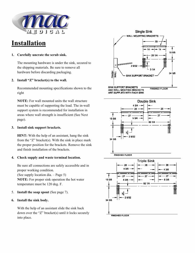
Installation 1. Carefully uncrate the scrub sink.
The mounting hardware is under the sink, secured to the shipping materials. Be sure to remove all hardware before discarding packaging.
2. Install “Z” bracket(s) to the wall.
Recommended mounting specifications shown to the right
NOTE: For wall mounted units the wall structure must be capable of supporting the load. The in-wall support system is recommended for installation in areas where wall strength is insufficient (See Next page).
3. Install sink support brackets.
HINT: With the help of an assistant, hang the sink from the “Z” bracket(s). With the sink in place mark the proper position for the brackets. Remove the sink and finish installation of the brackets.
4. Check supply and waste terminal location.
Be sure all connections are safely accessible and in proper working condition. (See supply location dia. – Page 5) NOTE: For proper sink operation the hot water temperature must be 120 deg. F.
5. Install the soap spout (See page 7).
6. Install the sink body.
With the help of an assistant slide the sink back down over the “Z” bracket(s) until it locks securely into place.
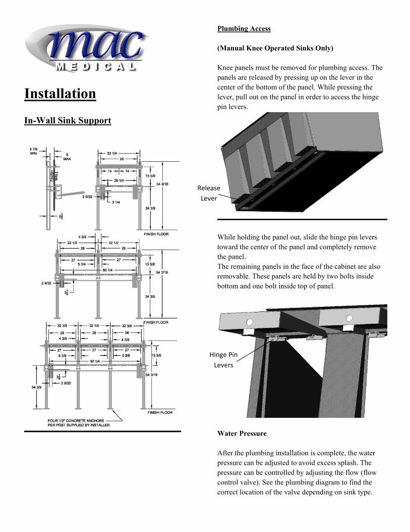
Installation
In-Wall Sink Support
Plumbing Access (Manual Knee Operated Sinks Only) Knee panels must be removed for plumbing access. The panels are released by pressing up on the lever in the center of the bottom of the panel. While pressing the lever, pull out on the panel in order to access the hinge pin levers.
While holding the panel out, slide the hinge pin levers toward the center of the panel and completely remove the panel. The remaining panels in the face of the cabinet are also removable. These panels are held by two bolts inside bottom and one bolt inside top of panel.
Water Pressure After the plumbing installation is complete, the water pressure can be adjusted to avoid excess splash. The pressure can be controlled by adjusting the flow (flow control valve). See the plumbing diagram to find the correct location of the valve depending on sink type.
Release
Lever
Hinge Pin
Levers

Plumbing Diagram Infra Red Self-Activated Sinks
Water Supply Locations For double and triple sinks all dimensions are equal to the diagram, relative to the sink basin.
Manual Knee Operated Sinks
4
15
10
16
1 2
3
5
6
14
6
15
8
3
10
16
1
2

Item No.
Description
Part No.
1 Thermostatic Mixing Valve S0009
2 Valve Handle S0010
3 Check Stop Strainer S0011
4 Infra Red Sensor S0012
5 Solenoid Valve for Infra Red S0013
6 Flow Control Valve S0024
7 Knee Operated Soap Pump S0028
8 Knee Operated Water Valve S0029
9 Thigh Operated Soap Pump S0030
10 Swivel Aerator S0032
11 Sink Dividers S0034
12 Soap Dispenser Spout S0041
13 Scrub Timers S0050
14 Timer Solenoid S0130
15 Check Valve S0131
16 Spout S0132M
Replacement Parts
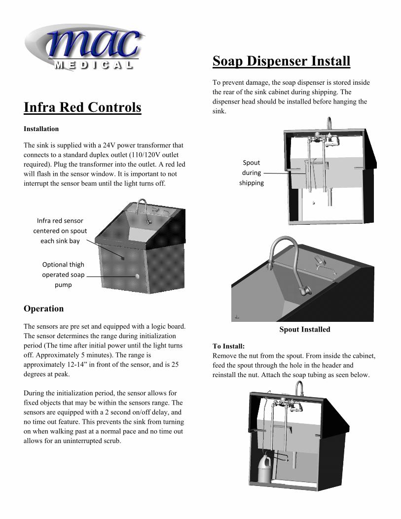
Infra Red Controls
Installation
The sink is supplied with a 24V power transformer that connects to a standard duplex outlet (110/120V outlet required). Plug the transformer into the outlet. A red led will flash in the sensor window. It is important to not interrupt the sensor beam until the light turns off.
Operation
The sensors are pre set and equipped with a logic board. The sensor determines the range during initialization period (The time after initial power until the light turns off. Approximately 5 minutes). The range is approximately 12-14” in front of the sensor, and is 25 degrees at peak. During the initialization period, the sensor allows for fixed objects that may be within the sensors range. The sensors are equipped with a 2 second on/off delay, and no time out feature. This prevents the sink from turning on when walking past at a normal pace and no time out allows for an uninterrupted scrub.
Soap Dispenser Install
To prevent damage, the soap dispenser is stored inside the rear of the sink cabinet during shipping. The dispenser head should be installed before hanging the sink.
Spout Installed
To Install: Remove the nut from the spout. From inside the cabinet, feed the spout through the hole in the header and reinstall the nut. Attach the soap tubing as seen below.
Infra red sensor
centered on spout
each sink bay
Optional thigh
operated soap
pump
Spout
during
shipping