Embed Size (px)
Citation preview
AIRBLAST
Surface Treatment SolutionsProduct Selection Guide
Beijer Oy - [email protected] - 09-61520550 - www.beijers.fi
AIRBLAST
PAGE 2
The Airblast GroupSince 1974 Airblast has been the world leader in providing blasting and painting solutions to the anticorrosion industries. With an unparalleled network of offices around the world Airblast works closely with our customers and distribution partners providing tried and tested equipment as well as developing customized solutions for specific applications.
The range of equipment sold by Airblast includes:● Traditional blasting machines & accessories● Shot blasting machines● Blasting & Painting rooms● Metallization rooms● Vacuum recovery systems● Abrasive recycling systems● Dust collectors● Dehumidification equipment● Inspection equipment
Airblast equipment is used in the following industries:● Metal & steel construction● Shipbuilding● Petrochemical● Oil and gas● Wind energy
Airblast-Abrasives B.V.Airblast-Abrasives B.V. was founded in 2014 and produces Steel Shot and Steel Grit of the highest quality. Airblast-Abrasives also supplies a complete range of abrasives in every size and hardness. The Airblast-Abrasives team is available to assist customers in selecting the right abrasive mixture and to analyze the work process in order to maximize efficiency. All abrasives are subject to strict quality control to ensure delivery of the best available materials.
Airblast Group CommitmentsAirblast is dedicated to maintain a profitable organization on a long term basis through ethically and morally sound business practices. By investing in the long term future of our organization, and those with whom we conduct business, Airblast believes that we can share sustained mutual success.
Our manufacturing facilities in Europe and the Far East produce fit for purpose quality products with region specific certification. All Airblast equipment is manufactured according to the highest relevant safety standards and passes our rigorous quality controls before dispatch.
Mindful of the environmental responsibilities faced by our generation Airblast is committed to a programme of research and development into technologies facilitating zero emission blasting and painting along with an education programme promoting planet friendly operations.
Beijer Oy - [email protected] - 09-61520550 - www.beijers.fi
AIRBLAST
PAGE 3
Table of Contents
Section 1 Blast Machines and Accessories PageBlast machines 6Mini blasters 19Bulk blasting systems 20Air receivers 21Remote control systems 22Clearline water filter / moisture separator 26Abrasive control valves 27
Section 2 Nozzles, Holders, Hoses, Couplings & ClampsBlast nozzles 36Nozzle holders 53Couplings and clamps 54Hoses 58
Section 3 Pipe Blasting & CoatingInternal pipe blasters 66Internal pipe coaters 73Semi-automatic winch system 85
Section 4 PPE - Personal Protection EquipmentAbrasive blasting helmets 88Paintspray hoods 94Helmet air filters & cartridges 96Climate control tubes 98Blast & paint clothing 101Gas Detection Monitor 102Lighting 104Cool vest 106
Section 5 Dust FreeAqua blasting 108Educt-O-Matic 111Mobile vacuum blast machines 114Blast cabinets 122Blast rooms 130UHP 131
Section 7 Material Handling PageVacuum recovery systems 146Abrasives recycling systems 151Vacuum cleaners 156
Section 8 Air TreatmentVenturi blowers 160Jet fans 161Aftercoolers 162Mobile dust collectors 163Dehumidifiers 165
Section 9 InspectionStep 1 - Climatic conditions 170Step 2 - Surface cleanliness 176Step 3 - Profile 182Step 4 - Thickness 185Step 5 - Adhesion 192Step 6 - Inspection 195
Section 11 Tips & TricksBlasting 216Painting 221Inspection 223Abrasives 227Conversion factors 228
Beijer Oy - [email protected] - 09-61520550 - www.beijers.fi

AIRBLAST
PAGE 5
Product PageBlast machines (blue) 6Blast machines (red) 13Mini blasters 19Bulk blasting systems 20Air receivers 21RCV-125 Remote control system 22RCV-50 Remote control system 24ACV Airblast combo valve 25Clearline water filter / moisture separator 26AP-7 Abrasive control valve 27FSV Flat sand valve 28SGV Steel grit valve 29GVA Abrasive membrane valve 30AMV Micro valve 31Thompson valve 32Thompson valve II 33
Section 1 - Blast Machines and Accessories
1
SECTION 1Beijer Oy - [email protected] - 09-61520550 - www.beijers.fi

AIRBLAST
PAGE 6
SPECIFICATIONSModel Dimensions (diameter x height in mm) Capacity (ltr.) Weight (kgs.)
ABSC-1028ABSC-1440ABSC-1648ABSC-2048ABSC-2452ABSC-2460
258 x 736358 x 1135486 x 1170486 x 1392608 x 1370608 x 1620
1860100140200280
246190105135151
Blast Machines (blue)
SECTION 1
A range of high production single and double chamber blast machines, manufactured in Europe and TÜV approved to suit the requirements of the anticorrosion industries. All machines are designed to guarantee fast filling, unrestricted airflow and easy access for inspection and maintenance. High precision abrasive metering valves give accurate delivery of all types of blasting media.
ORDERING INFORMATIONStandard package including:Blast Machine with AP-7/Micro Valve, RCV-125 Remote Control System incl. Silencer, DMH-125Deadman Handle and Remote Control Hose, Clearline Moisture Separator, Screen, Cover, Blast Hose Nozzle Holder and Coupling, Tungsten Carbide lined Blast Nozzle, HAF Helmet Air Filter, Helmet Air Hose, Blast Helmet with Spare Lenses, Leather/Cotton Overall and a pair of Leather Blasting Gloves.
Part no. Description Part no. Description
1001910 System-3 1008917 System-6
1004917 System-4 1010068 System-7
1006917 System-5 1012068 System-8
1144300 Twin line Control Hose, 5 mtr., coupled
1144400 Twin line Control Hose, 20 mtr., coupled
1144500 Twin line Control Hose, 40 mtr., coupled
1171000 ARC-H Pneumatic Deadman Handle - small type
1203000 DMH-125 Pneumatic Deadman Handle
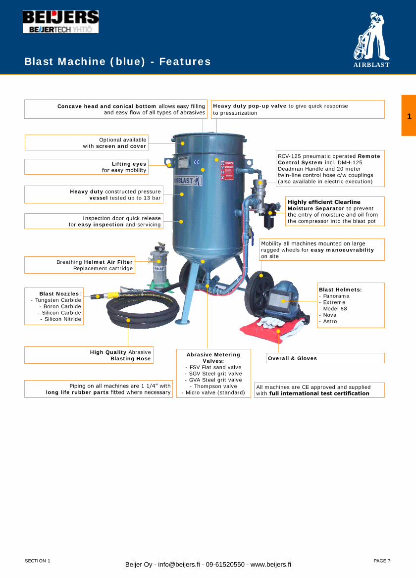
Features:Concave head and conical bottom allows easy filling • and smooth flow of all types of abrasive.Heavy duty pop-up valve to give quick response to pressurization.• Lifting eyes for easy mobility. • Mobility all machines mounted on large rugged wheels for easy manoeuvrability on site. • Working pressure of 12 bar. • A full range of abrasive metering valves are available.• Standard fitted with:• - RCV-125 pneumatic operated Remote Control System incl. DMH-125 Deadman Handle and 20 meter twin-line•
control hose c/w couplings. - Clearline Moisture Separator to prevent the entry of moisture and oil from the compressor into the blast pot.
All machines are CE marked and TÜV approved.•
Beijer Oy - [email protected] - 09-61520550 - www.beijers.fi
AIRBLAST
PAGE 7
RCV-125 pneumatic operated Remote Control System incl. DMH-125Deadman Handle and 20 metertwin-line control hose c/w couplings (also available in electric execution)
Highly efficient Clearline Moisture Separator to prevent the entry of moisture and oil from the compressor into the blast pot
Concave head and conical bottom allows easy fillingand easy flow of all types of abrasives
Heavy duty constructed pressurevessel tested up to 13 bar
Breathing Helmet Air FilterReplacement cartridge
High Quality AbrasiveBlasting Hose
Blast Nozzles:- Tungsten Carbide
- Boron Carbide- Silicon Carbide- Silicon Nitride
Abrasive Metering Valves:
- FSV Flat sand valve- SGV Steel grit valve- GVA Steel grit valve
- Thompson valve- Micro valve (standard)
Mobility all machines mounted on largerugged wheels for easy manoeuvrability on site
Blast Helmets:- Panorama- Extreme- Model 88- Nova- Astro
Piping on all machines are 1 1/4” with long life rubber parts fitted where necessary
All machines are CE approved and supplied with full international test certification
Optional availablewith screen and cover
Overall & Gloves
Lifting eyesfor easy mobility
Heavy duty pop-up valve to give quick responseto pressurization
Inspection door quick releasefor easy inspection and servicing
Blast Machine (blue) - Features
1
SECTION 1 Beijer Oy - [email protected] - 09-61520550 - www.beijers.fi

AIRBLAST
PAGE 8
Blast Machine (blue) Configurator - 18/60 liters
Part no. Capacity Metering Valves Operation Other Options
18 li
ter
60 li
ter
AP-
7 Abr
asiv
e Con
trol
Val
ve ½
”
GVA
-12
Abr
asiv
e M
eter
ing
Valv
e
FSV F
lat
San
d Va
lve
1¼”
GVA
-32
Abr
asiv
e M
eter
ing
Valv
e
SG
V S
teel
Grit
Valv
e
Mic
ro V
alve
Man
ual O
pera
tion
RCV-
50 R
emot
e Con
trol
Sys
tem
RCV-
125
Rem
ote
Con
trol
Sys
tem
Cle
arlin
e M
oisu
re S
epar
ator
½”
Cle
arlin
e M
oisu
re S
epar
ator
1½
”
Saf
ety
Valv
e Ass
embl
y
1001010 ● ● ●
1001020 ● ● ● ●
1001030 ● ● ●
1001040 ● ● ● ●
1001060 ● ● ● ●
1001310 ● ● ●
1001330 ● ● ●
1003010 ● ● ●
1003020 ● ● ●
1003030 ● ● ●
1003040 ● ● ● ●
1003050 ● ● ● ●
1003060 ● ● ● ● ●
1003310 ● ● ●
1003330 ● ● ●
1004010 ● ● ●
1004020 ● ● ● ●
1004030 ● ● ●
1004040 ● ● ● ●
1004050 ● ● ● ●
1004060 ● ● ● ● ●
1004911 ● ● ●
1004912 ● ● ● ●
1004913 ● ● ●
1004914 ● ● ● ●
1004915 ● ● ● ●
1004916 ● ● ● ● ●
Other configurations are available upon request.
SECTION 1Beijer Oy - [email protected] - 09-61520550 - www.beijers.fi
AIRBLAST
PAGE 9
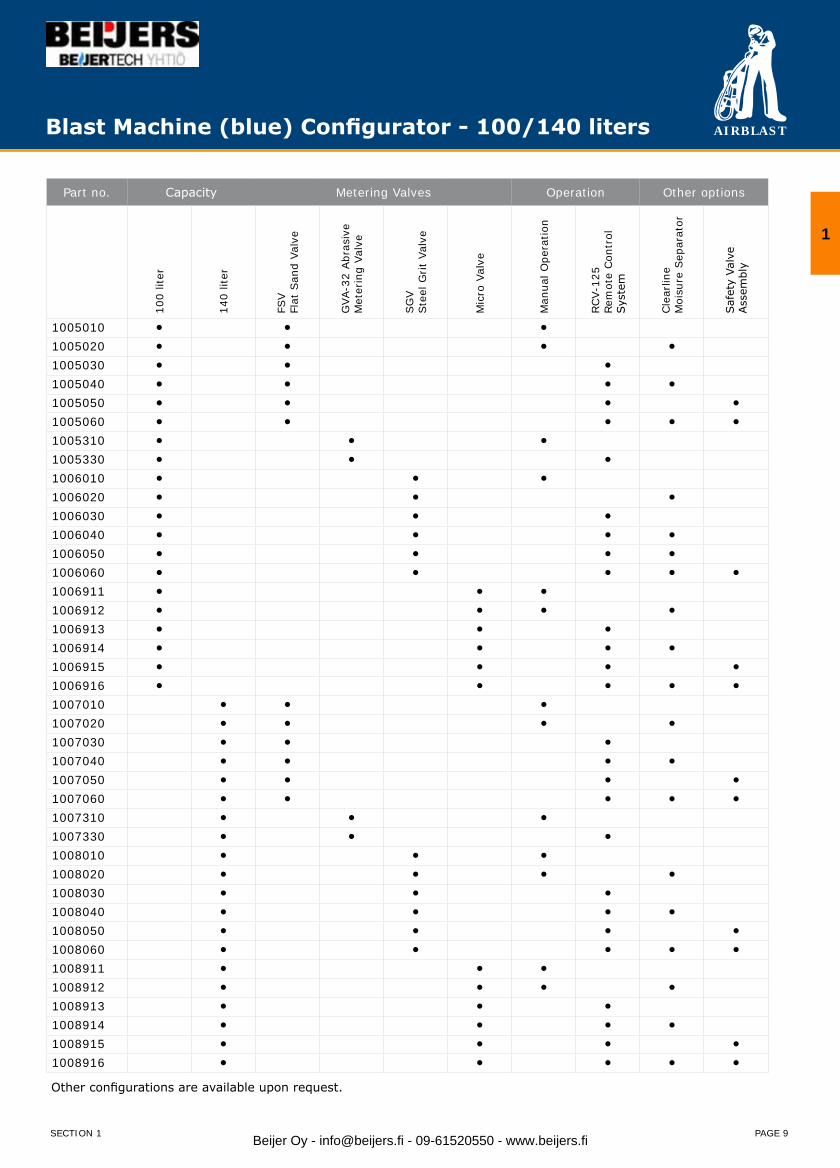
Part no. Capacity Metering Valves Operation Other options
100
liter
140
liter
FSV
Flat
San
d Va
lve
GVA
-32
Abr
asiv
eM
eter
ing
Valv
e
SG
VSte
el G
rit
Valv
e
Mic
ro V
alve
Man
ual O
pera
tion
RCV-
125
Rem
ote
Con
trol
Syst
em
Cle
arlin
eM
oisu
re S
epar
ator
Saf
ety
Valv
eAss
embl
y
1005010 ● ● ●
1005020 ● ● ● ●
1005030 ● ● ●
1005040 ● ● ● ●
1005050 ● ● ● ●
1005060 ● ● ● ● ●
1005310 ● ● ●
1005330 ● ● ●
1006010 ● ● ●
1006020 ● ● ●
1006030 ● ● ●
1006040 ● ● ● ●
1006050 ● ● ● ●
1006060 ● ● ● ● ●
1006911 ● ● ●
1006912 ● ● ● ●
1006913 ● ● ●
1006914 ● ● ● ●
1006915 ● ● ● ●
1006916 ● ● ● ● ●
1007010 ● ● ●
1007020 ● ● ● ●
1007030 ● ● ●
1007040 ● ● ● ●
1007050 ● ● ● ●
1007060 ● ● ● ● ●
1007310 ● ● ●
1007330 ● ● ●
1008010 ● ● ●
1008020 ● ● ● ●
1008030 ● ● ●
1008040 ● ● ● ●
1008050 ● ● ● ●
1008060 ● ● ● ● ●
1008911 ● ● ●
1008912 ● ● ● ●
1008913 ● ● ●
1008914 ● ● ● ●
1008915 ● ● ● ●
1008916 ● ● ● ● ●
Other configurations are available upon request.
Blast Machine (blue) Configurator - 100/140 liters
1
SECTION 1 Beijer Oy - [email protected] - 09-61520550 - www.beijers.fi
AIRBLAST
PAGE 10
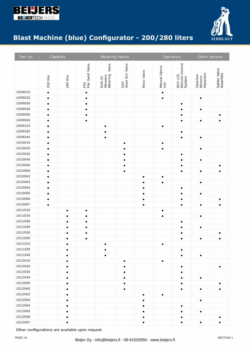
Blast Machine (blue) Configurator - 200/280 liters
Part no. Capacity Metering Valves Operation Other options
200
liter
280
liter
FSV
Flat
San
d Va
lve
GVA
-32
Abr
asiv
eM
eter
ing
Val
ve
SG
VSte
el G
rit
Valv
e
Mic
ro V
alve
Man
ual O
pera
-tio
n
RCV-
125
Rem
ote
Con
trol
Sy
stem
Cle
arlin
eM
oisu
reSep
arat
or
Saf
ety
Valv
eAss
embl
y
1009010 ● ● ●1009020 ● ● ● ●1009030 ● ● ●1009040 ● ● ● ●1009050 ● ● ● ●1009060 ● ● ● ● ●1009310 ● ● ●1009330 ● ● ●1009340 ● ● ● ●1010010 ● ● ●1010020 ● ● ● ●1010030 ● ● ●1010040 ● ● ● ●1010050 ● ● ● ●1010060 ● ● ● ● ●1010062 ● ● ●1010063 ● ● ● ●1010064 ● ● ●1010065 ● ● ● ●1010066 ● ● ● ●1010067 ● ● ● ● ●1011010 ● ● ●1011020 ● ● ● ●1011030 ● ● ●1011040 ● ● ● ●1011050 ● ● ● ●1011060 ● ● ● ● ●1011310 ● ● ●1011330 ● ● ●1011340 ● ● ● ●1012010 ● ● ●1012020 ● ● ● ●1012030 ● ● ●1012040 ● ● ● ●1012050 ● ● ● ●1012060 ● ● ● ● ●1012062 ● ● ●1012063 ● ● ●1012064 ● ● ●1012065 ● ● ● ●1012066 ● ● ● ●1012067 ● ● ● ● ●
Other configurations are available upon request.
SECTION 1Beijer Oy - [email protected] - 09-61520550 - www.beijers.fi

AIRBLAST
PAGE 11
Blast Machine (blue) 18 ltr. - Drawing & Part List
1
SECTION 1
Blast Machine (blue) 18 ltr. - Parts
Item Part no. Description Item Part no. Description
1 1072000 Pop-up valve seat retainer bolt 14 1089000 Pipe 150mm, ½”, MM
2 1095000 Gasket for pop-up valve seat retainer 15 1087000 Pipe 80mm, ½”, MM
3 1074000 Pop-up valve seat retainer 16 1081000 Pipe 50mm, ½”, MM
4 1073000 AP-5 Pop-up O-ring 17 6026000 AP-7 Abrasive control valve, ½”, FF
5 1075000 AP-2 Pop-up valve with shaft 18 2225300 Pipe 30 mm, ½”, MM
6 1077000 Inner pipe, ½”, M 19 2170200 KAG-12 Quick coupling, ½”, M
7 2197300 Elbow no. 90, ½”, FF 20 2164000 CQG-0 Rubber coupling gasket
8 1079000 Inner pipe, ½”, MM 21 4056001 Clearline, ½”, FF
9 2225300 Hex nipple, ½”, MM 22 1122000 RCV-50 incl. Silencer
10 2211300 T-piece, ½”, FFF 23 1079000 Pipe 100 mm, ½”, MM
11 2199300 Elbow, ½”, MF 1070000 Cover for ABSC-1028 (not shown)
12 2249300 Union, ½”, MF 1071000 Screen for ABSC-1028 (not shown)
13 1090000 AP-1 Air valve, ½”, FF
Beijer Oy - [email protected] - 09-61520550 - www.beijers.fi
AIRBLAST
PAGE 12
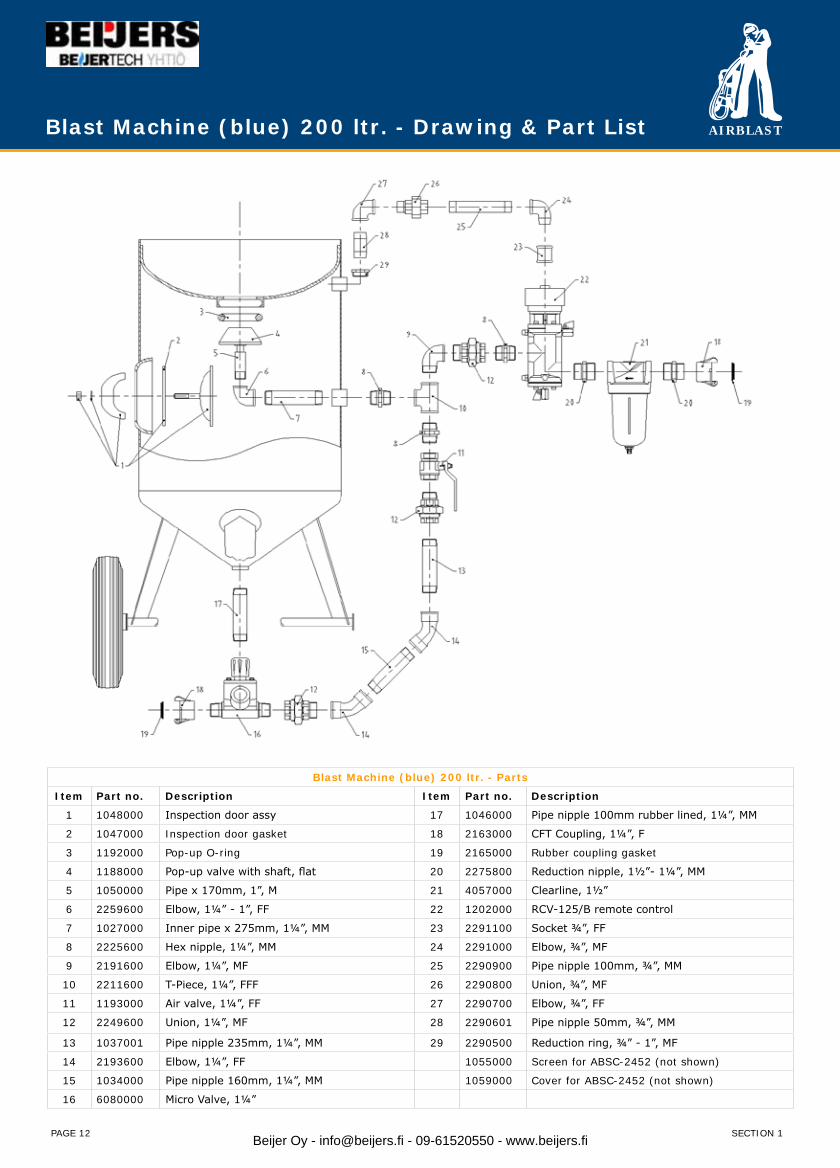
Blast Machine (blue) 200 ltr. - Drawing & Part List
Blast Machine (blue) 200 ltr. - Parts
Item Part no. Description Item Part no. Description
1 1048000 Inspection door assy 17 1046000 Pipe nipple 100mm rubber lined, 1¼”, MM
2 1047000 Inspection door gasket 18 2163000 CFT Coupling, 1¼”, F
3 1192000 Pop-up O-ring 19 2165000 Rubber coupling gasket
4 1188000 Pop-up valve with shaft, flat 20 2275800 Reduction nipple, 1½”- 1¼”, MM
5 1050000 Pipe x 170mm, 1”, M 21 4057000 Clearline, 1½”
6 2259600 Elbow, 1¼” - 1”, FF 22 1202000 RCV-125/B remote control
7 1027000 Inner pipe x 275mm, 1¼”, MM 23 2291100 Socket ¾”, FF
8 2225600 Hex nipple, 1¼”, MM 24 2291000 Elbow, ¾”, MF
9 2191600 Elbow, 1¼”, MF 25 2290900 Pipe nipple 100mm, ¾”, MM
10 2211600 T-Piece, 1¼”, FFF 26 2290800 Union, ¾”, MF
11 1193000 Air valve, 1¼”, FF 27 2290700 Elbow, ¾”, FF
12 2249600 Union, 1¼”, MF 28 2290601 Pipe nipple 50mm, ¾”, MM
13 1037001 Pipe nipple 235mm, 1¼”, MM 29 2290500 Reduction ring, ¾” - 1”, MF
14 2193600 Elbow, 1¼”, FF 1055000 Screen for ABSC-2452 (not shown)
15 1034000 Pipe nipple 160mm, 1¼”, MM 1059000 Cover for ABSC-2452 (not shown)
16 6080000 Micro Valve, 1¼”
SECTION 1Beijer Oy - [email protected] - 09-61520550 - www.beijers.fi
AIRBLAST
PAGE 13
Blast Machine (blue) 200 ltr. - Parts
Item Part no. Description Item Part no. Description
1 1048000 Inspection door assy 17 1046000 Pipe nipple 100mm rubber lined, 1¼”, MM
2 1047000 Inspection door gasket 18 2163000 CFT Coupling, 1¼”, F
3 1192000 Pop-up O-ring 19 2165000 Rubber coupling gasket
4 1188000 Pop-up valve with shaft, flat 20 2275800 Reduction nipple, 1½”- 1¼”, MM
5 1050000 Pipe x 170mm, 1”, M 21 4057000 Clearline, 1½”
6 2259600 Elbow, 1¼” - 1”, FF 22 1202000 RCV-125/B remote control
7 1027000 Inner pipe x 275mm, 1¼”, MM 23 2291100 Socket ¾”, FF
8 2225600 Hex nipple, 1¼”, MM 24 2291000 Elbow, ¾”, MF
9 2191600 Elbow, 1¼”, MF 25 2290900 Pipe nipple 100mm, ¾”, MM
10 2211600 T-Piece, 1¼”, FFF 26 2290800 Union, ¾”, MF
11 1193000 Air valve, 1¼”, FF 27 2290700 Elbow, ¾”, FF
12 2249600 Union, 1¼”, MF 28 2290601 Pipe nipple 50mm, ¾”, MM
13 1037001 Pipe nipple 235mm, 1¼”, MM 29 2290500 Reduction ring, ¾” - 1”, MF
14 2193600 Elbow, 1¼”, FF 1055000 Screen for ABSC-2452 (not shown)
15 1034000 Pipe nipple 160mm, 1¼”, MM 1059000 Cover for ABSC-2452 (not shown)
16 6080000 Micro Valve, 1¼”
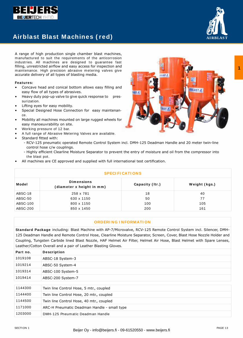
A range of high production single chamber blast machines, manufactured to suit the requirements of the anticorrosion industries. All machines are designed to guarantee fast filling, unrestricted airflow and easy access for inspection and maintenance. High precision abrasive metering valves give accurate delivery of all types of blasting media.
Features:Concave head and conical bottom allows easy filling and • easy flow of all types of abrasives.Heavy duty pop-up valve to give quick response to pres-• surization.Lifting eyes for easy mobility. • Special Designed Hose Connection for easy maintenan-• ce. Mobility all machines mounted on large rugged wheels for • easy manoeuvrability on site. Working pressure of 12 bar. • A full range of Abrasive Metering Valves are available.• Standard fitted with:•
- RCV-125 pneumatic operated Remote Control System incl. DMH-125 Deadman Handle and 20 meter twin-line control hose c/w couplings. - Highly efficient Clearline Moisture Separator to prevent the entry of moisture and oil from the compressor into the blast pot.
All machines are CE approved and supplied with full international test certification.•
ORDERING INFORMATION
Standard Package including: Blast Machine with AP-7/Microvalve, RCV-125 Remote Control System incl. Silencer, DMH-125 Deadman Handle and Remote Control Hose, Clearline Moisture Separator, Screen, Cover, Blast Hose Nozzle Holder and Coupling, Tungsten Carbide lined Blast Nozzle, HAF Helmet Air Filter, Helmet Air Hose, Blast Helmet with Spare Lenses, Leather/Cotton Overall and a pair of Leather Blasting Gloves.
Part no. Description
1019108 ABSC-18 System-3
1019214 ABSC-50 System-4
1019314 ABSC-100 System-5
1019414 ABSC-200 System-7
1144300 Twin line Control Hose, 5 mtr., coupled
1144400 Twin line Control Hose, 20 mtr., coupled
1144500 Twin line Control Hose, 40 mtr., coupled
1171000 ARC-H Pneumatic Deadman Handle - small type
1203000 DMH-125 Pneumatic Deadman Handle
Airblast Blast Machines (red)
SPECIFICATIONS
ModelDimensions
(diameter x height in mm)Capacity (ltr.) Weight (kgs.)
ABSC-18ABSC-50 ABSC-100ABSC-200
258 x 781630 x 1150800 x 1150850 x 1450
1850100200
4077105161
1
SECTION 1 Beijer Oy - [email protected] - 09-61520550 - www.beijers.fi
AIRBLAST
PAGE 14
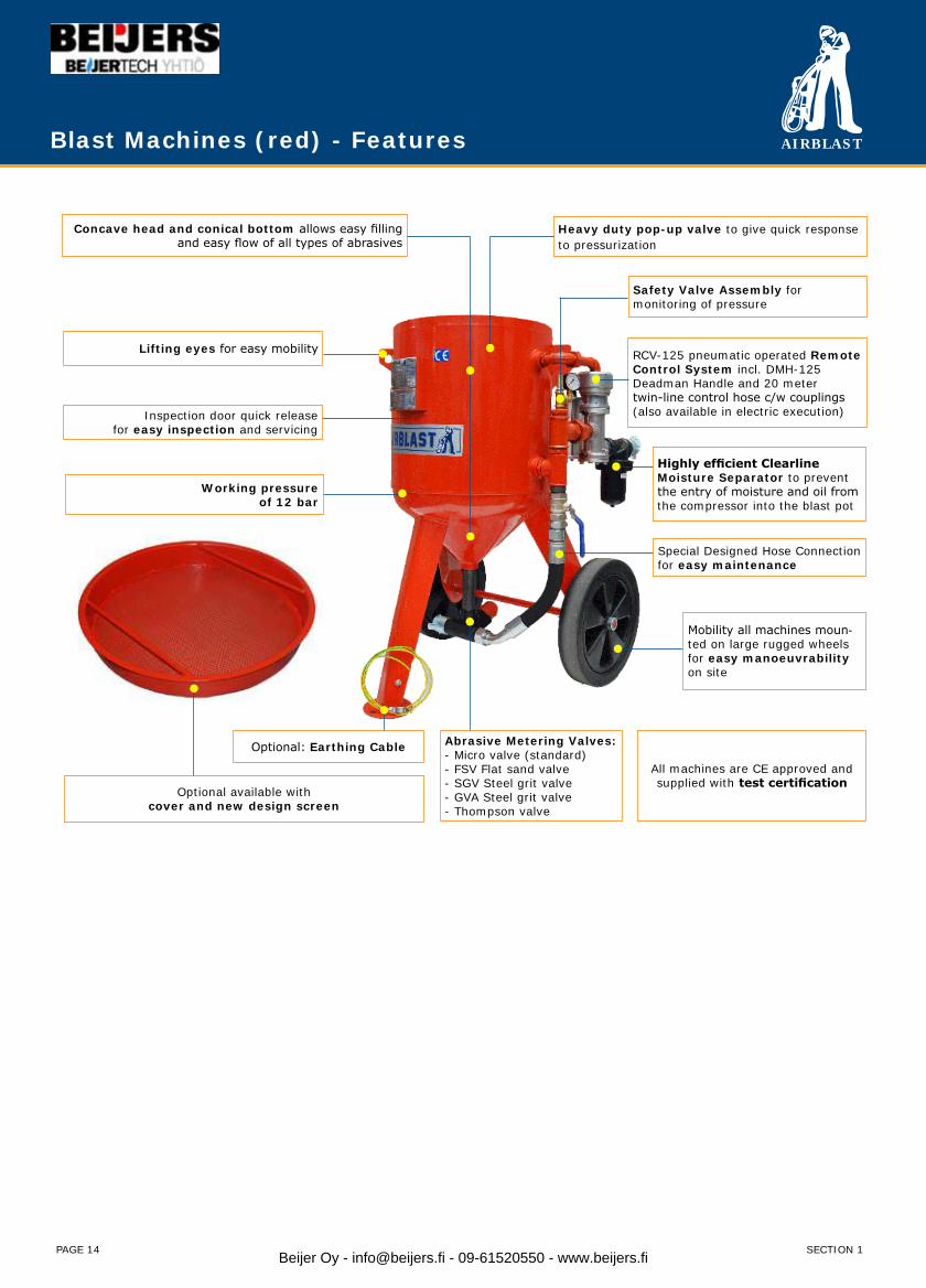
Blast Machines (red) - Features
RCV-125 pneumatic operated Remote Control System incl. DMH-125Deadman Handle and 20 metertwin-line control hose c/w couplings (also available in electric execution)
Concave head and conical bottom allows easy fillingand easy flow of all types of abrasives
Special Designed Hose Connection for easy maintenance
Abrasive Metering Valves:- Micro valve (standard)- FSV Flat sand valve- SGV Steel grit valve- GVA Steel grit valve- Thompson valve
Mobility all machines moun-ted on large rugged wheels for easy manoeuvrability on site
All machines are CE approved and supplied with test certification
Optional available withcover and new design screen
Heavy duty pop-up valve to give quick responseto pressurization
Inspection door quick releasefor easy inspection and servicing
Working pressureof 12 bar
Highly efficient Clearline Moisture Separator to prevent the entry of moisture and oil from the compressor into the blast pot
Lifting eyes for easy mobility
Safety Valve Assembly formonitoring of pressure
Optional: Earthing Cable
SECTION 1Beijer Oy - [email protected] - 09-61520550 - www.beijers.fi
AIRBLAST
PAGE 15
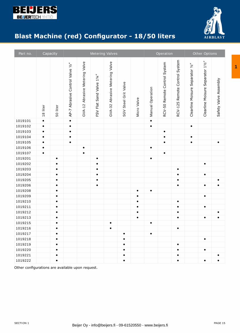
Blast Machine (red) Configurator - 18/50 liters
Part no. Capacity Metering Valves Operation Other Options
18 li
ter
50 li
ter
AP-
7 Abr
asiv
e Con
trol
Val
ve ½
”
GVA
-12
Abr
asiv
e M
eter
ing
Valv
e
FSV F
lat
San
d Va
lve
1¼”
GVA
-32
Abr
asiv
e M
eter
ing
Valv
e
SG
V S
teel
Grit
Valv
e
Mic
ro V
alve
Man
ual O
pera
tion
RCV-
50 R
emot
e Con
trol
Sys
tem
RCV-
125
Rem
ote
Con
trol
Sys
tem
Cle
arlin
e M
oisu
re S
epar
ator
½”
Cle
arlin
e M
oisu
re S
epar
ator
1½
”
Saf
ety
Valv
e Ass
embl
y
1019101 ● ● ●
1019102 ● ● ● ●
1019103 ● ● ●
1019104 ● ● ● ●
1019105 ● ● ● ● ●
1019106 ● ● ●
1019107 ● ● ●
1019201 ● ● ●
1019202 ● ● ●
1019203 ● ● ●
1019204 ● ● ● ●
1019205 ● ● ● ●
1019206 ● ● ● ● ●
1019208 ● ● ●
1019209 ● ● ●
1019210 ● ● ●
1019211 ● ● ● ●
1019212 ● ● ● ●
1019213 ● ● ● ● ●
1019215 ● ● ●
1019216 ● ● ●
1019217 ● ● ●
1019218 ● ● ●
1019219 ● ● ●
1019220 ● ● ● ●
1019221 ● ● ● ●
1019222 ● ● ● ● ●
Other configurations are available upon request.
1
SECTION 1 Beijer Oy - [email protected] - 09-61520550 - www.beijers.fi

AIRBLAST
PAGE 16
Blast Machines (red) Configurator - 100/200 liters
Part no. Capacity Metering Valves Operation Other options
100
liter
200
liter
FSV
Flat
San
d Va
lve
GVA
-32
Abr
asiv
eM
eter
ing
Valv
e
SG
VSte
el G
rit
Valv
e
Mic
ro V
alve
Man
ual O
pera
tion
RCV-
125
Rem
ote
Con
trol
Sy
stem
Cle
arlin
eM
oisu
re S
epar
ator
Saf
ety
Valv
eAss
embl
y
1019301 ● ● ●
1019302 ● ● ● ●
1019303 ● ● ●
1019304 ● ● ● ●
1019305 ● ● ● ●
1019306 ● ● ● ● ●
1019308 ● ● ●
1019309 ● ● ●
1019310 ● ● ●
1019311 ● ● ● ●
1019312 ● ● ● ●
1019313 ● ● ● ● ●
1019315 ● ● ●
1019316 ● ● ●
1019317 ● ● ●
1019318 ● ● ● ●
1019319 ● ● ●
1019320 ● ● ● ●
1019321 ● ● ● ●
1019322 ● ● ● ● ●
1019401 ● ● ●
1019402 ● ● ● ●
1019403 ● ● ●
1019404 ● ● ● ●
1019405 ● ● ● ●
1019406 ● ● ● ● ●
1019408 ● ● ●
1019409 ● ● ● ●
1019410 ● ● ●
1019411 ● ● ● ●
1019412 ● ● ● ●
1019413 ● ● ● ● ●
1019415 ● ● ●
1019416 ● ● ●
1019417 ● ● ● ●
1019418 ● ● ●
1019419 ● ● ●
1019420 ● ● ●
1019421 ● ● ● ●
1019422 ● ● ● ●
1019423 ● ● ● ● ●
Other configurations are available upon request.
SECTION 1Beijer Oy - [email protected] - 09-61520550 - www.beijers.fi
AIRBLAST
PAGE 17
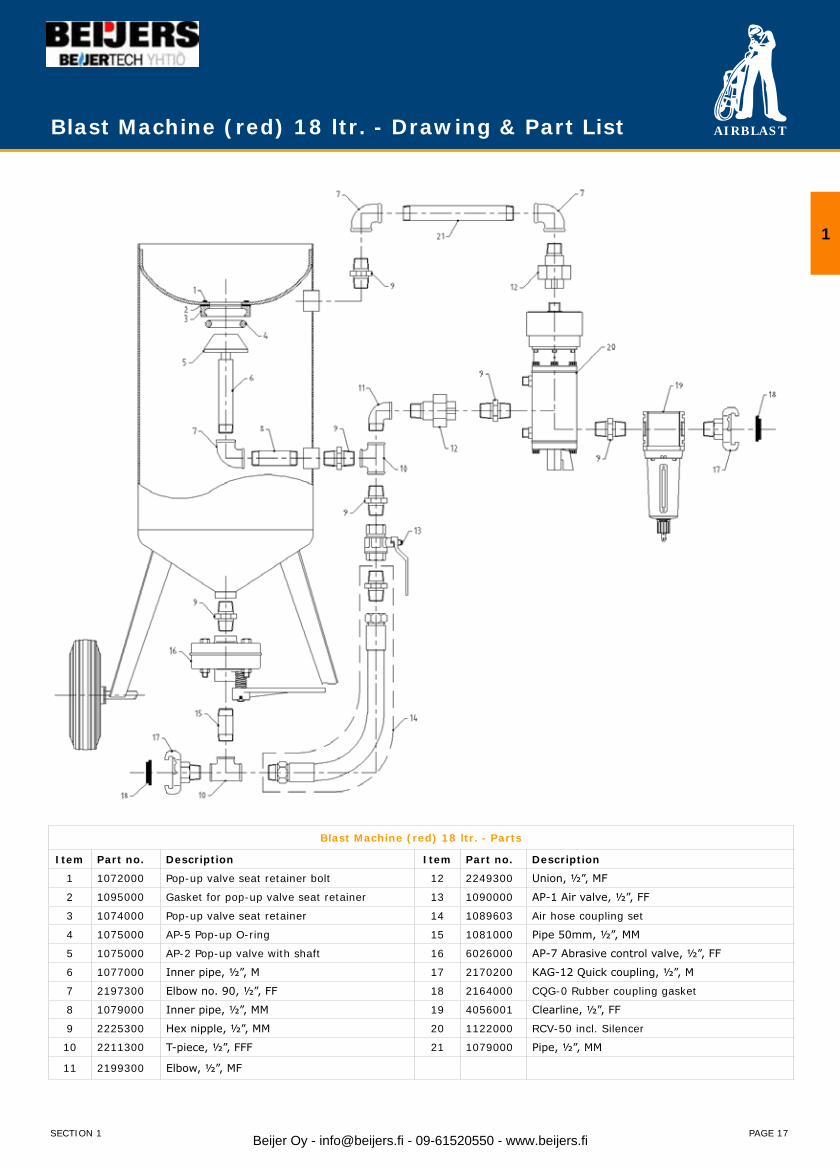
Blast Machine (red) 18 ltr. - Drawing & Part List
1
SECTION 1
Blast Machine (red) 18 ltr. - Parts
Item Part no. Description Item Part no. Description
1 1072000 Pop-up valve seat retainer bolt 12 2249300 Union, ½”, MF
2 1095000 Gasket for pop-up valve seat retainer 13 1090000 AP-1 Air valve, ½”, FF
3 1074000 Pop-up valve seat retainer 14 1089603 Air hose coupling set
4 1075000 AP-5 Pop-up O-ring 15 1081000 Pipe 50mm, ½”, MM
5 1075000 AP-2 Pop-up valve with shaft 16 6026000 AP-7 Abrasive control valve, ½”, FF
6 1077000 Inner pipe, ½”, M 17 2170200 KAG-12 Quick coupling, ½”, M
7 2197300 Elbow no. 90, ½”, FF 18 2164000 CQG-0 Rubber coupling gasket
8 1079000 Inner pipe, ½”, MM 19 4056001 Clearline, ½”, FF
9 2225300 Hex nipple, ½”, MM 20 1122000 RCV-50 incl. Silencer
10 2211300 T-piece, ½”, FFF 21 1079000 Pipe, ½”, MM
11 2199300 Elbow, ½”, MF
Beijer Oy - [email protected] - 09-61520550 - www.beijers.fi

AIRBLAST
PAGE 18
Blast Machine (red) 200 ltr. - Drawing & Part List
Blast Machine (red) 200 ltr. - Parts
Item Part no. Description Item Part no. Description
1 1048000 Inspection door assy 15 1046000 Pipe nipple 100mm rubber lined, 1¼”, MM
2 1047000 Inspection door gasket 16 2163000 CFT Coupling, 1¼”, F
3 1192000 Pop-up O-ring 17 2165000 Rubber coupling gasket
4 1188000 Pop-up valve with shaft, flat 18 2275800 Reduction nipple, 1½”- 1¼”, MM
5 1050000 Pipe x 170mm, 1”, M 19 4057000 Clearline, 1½”
6 2259600 Elbow 1¼” - 1”, FF 20 1202000 RCV-125/B remote control
7 1027000 Inner pipe x 275mm, 1¼”, MM 21 2291100 Socket ¾”, FF
8 2225600 Hex nipple, 1¼”, MM 22 2291000 Elbow, ¾”, MF
9 2191600 Elbow, 1¼”, MF 23 2290900 Pipe nipple 100mm, ¾”, MM
10 2211600 T-Piece, 1¼”, FFF 24 2290800 Union, ¾”, MF
11 1193000 Air valve, 1¼”, FF 25 2290700 Elbow, ¾”, FF
12 2249600 Union, 1¼”, MF 26 2290601 Pipe nipple 50mm, ¾”, MM
13 1089600 Coupling set air hose 200 liter micro 27 2290500 Reduction ring, ¾” - 1”, MF
14 6080000 Micro Valve, 1¼”
SECTION 1Beijer Oy - [email protected] - 09-61520550 - www.beijers.fi
AIRBLAST
PAGE 19
Blast Machine (red) 200 ltr. - Parts
Item Part no. Description Item Part no. Description
1 1048000 Inspection door assy 15 1046000 Pipe nipple 100mm rubber lined, 1¼”, MM
2 1047000 Inspection door gasket 16 2163000 CFT Coupling, 1¼”, F
3 1192000 Pop-up O-ring 17 2165000 Rubber coupling gasket
4 1188000 Pop-up valve with shaft, flat 18 2275800 Reduction nipple, 1½”- 1¼”, MM
5 1050000 Pipe x 170mm, 1”, M 19 4057000 Clearline, 1½”
6 2259600 Elbow 1¼” - 1”, FF 20 1202000 RCV-125/B remote control
7 1027000 Inner pipe x 275mm, 1¼”, MM 21 2291100 Socket ¾”, FF
8 2225600 Hex nipple, 1¼”, MM 22 2291000 Elbow, ¾”, MF
9 2191600 Elbow, 1¼”, MF 23 2290900 Pipe nipple 100mm, ¾”, MM
10 2211600 T-Piece, 1¼”, FFF 24 2290800 Union, ¾”, MF
11 1193000 Air valve, 1¼”, FF 25 2290700 Elbow, ¾”, FF
12 2249600 Union, 1¼”, MF 26 2290601 Pipe nipple 50mm, ¾”, MM
13 1089600 Coupling set air hose 200 liter micro 27 2290500 Reduction ring, ¾” - 1”, MF
14 6080000 Micro Valve, 1¼”
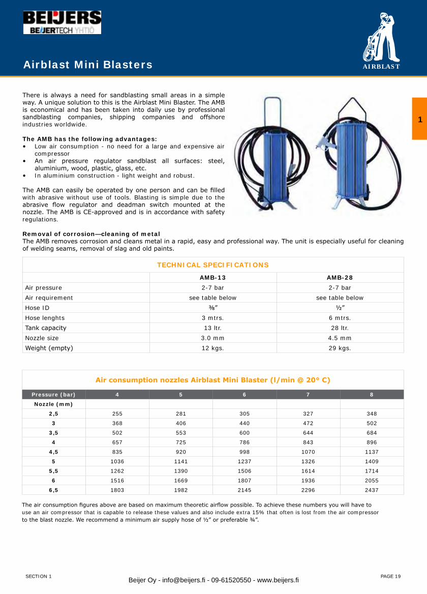
Airblast Mini Blasters
There is always a need for sandblasting small areas in a simple way. A unique solution to this is the Airblast Mini Blaster. The AMB is economical and has been taken into daily use by professional sandblasting companies, shipping companies and offshore industries worldwide.
The AMB has the following advantages:Low air consumption - no need for a large and expensive air•compressorAn air pressure regulator sandblast all surfaces: steel,•aluminium, wood, plastic, glass, etc.In aluminium construction - light weight and robust.•
The AMB can easily be operated by one person and can be filled with abrasive without use of tools. Blasting is simple due to the abrasive flow regulator and deadman switch mounted at the nozzle. The AMB is CE-approved and is in accordance with safety regulations.
Removal of corrosion—cleaning of metalThe AMB removes corrosion and cleans metal in a rapid, easy and professional way. The unit is especially useful for cleaning of welding seams, removal of slag and old paints.
Air consumption nozzles Airblast Mini Blaster (l/min @ 20° C)
Pressure (bar) 4 5 6 7 8
Nozzle (mm)
2,5 255 281 305 327 348
3 368 406 440 472 502
3,5 502 553 600 644 684
4 657 725 786 843 896
4,5 835 920 998 1070 1137
5 1036 1141 1237 1326 1409
5,5 1262 1390 1506 1614 1714
6 1516 1669 1807 1936 2055
6,5 1803 1982 2145 2296 2437
The air consumption figures above are based on maximum theoretic airflow possible. To achieve these numbers you will have touse an air compressor that is capable to release these values and also include extra 15% that often is lost from the air compressorto the blast nozzle. We recommend a minimum air supply hose of ½” or preferable ¾”.
TECHNICAL SPECIFICATIONS
AMB-13 AMB-28Air pressure 2-7 bar 2-7 barAir requirement see table below see table belowHose ID ⅜” ½”Hose lenghts 3 mtrs. 6 mtrs.Tank capacity 13 ltr. 28 ltr.Nozzle size 3.0 mm 4.5 mmWeight (empty) 12 kgs. 29 kgs.
1
SECTION 1 Beijer Oy - [email protected] - 09-61520550 - www.beijers.fi
AIRBLAST
PAGE 20
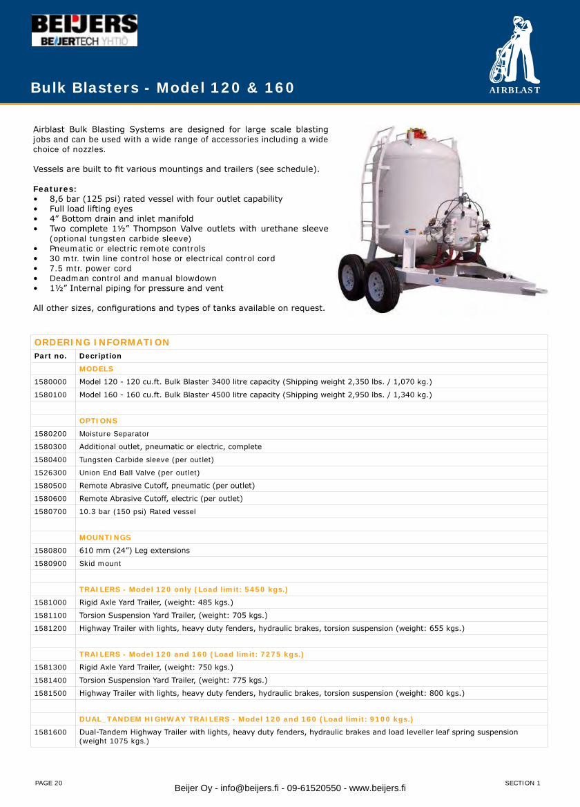
Bulk Blasters - Model 120 & 160
Airblast Bulk Blasting Systems are designed for large scale blasting jobs and can be used with a wide range of accessories including a wide choice of nozzles.
Vessels are built to fit various mountings and trailers (see schedule).
Features:8,6 bar (125 psi) rated vessel with four outlet capability• Full load lifting eyes• 4” Bottom drain and inlet manifold• Two complete 1½” Thompson Valve outlets with urethane sleeve • (optional tungsten carbide sleeve)Pneumatic or electric remote controls• 30 mtr. twin line control hose or electrical control cord• 7.5 mtr. power cord• Deadman control and manual blowdown• 1½” Internal piping for pressure and vent•
All other sizes, configurations and types of tanks available on request.
ORDERING INFORMATIONPart no. Decription
MODELS
1580000 Model 120 - 120 cu.ft. Bulk Blaster 3400 litre capacity (Shipping weight 2,350 lbs. / 1,070 kg.)
1580100 Model 160 - 160 cu.ft. Bulk Blaster 4500 litre capacity (Shipping weight 2,950 lbs. / 1,340 kg.)
OPTIONS
1580200 Moisture Separator
1580300 Additional outlet, pneumatic or electric, complete
1580400 Tungsten Carbide sleeve (per outlet)
1526300 Union End Ball Valve (per outlet)
1580500 Remote Abrasive Cutoff, pneumatic (per outlet)
1580600 Remote Abrasive Cutoff, electric (per outlet)
1580700 10.3 bar (150 psi) Rated vessel
MOUNTINGS
1580800 610 mm (24”) Leg extensions
1580900 Skid mount
TRAILERS - Model 120 only (Load limit: 5450 kgs.)
1581000 Rigid Axle Yard Trailer, (weight: 485 kgs.)
1581100 Torsion Suspension Yard Trailer, (weight: 705 kgs.)
1581200 Highway Trailer with lights, heavy duty fenders, hydraulic brakes, torsion suspension (weight: 655 kgs.)
TRAILERS - Model 120 and 160 (Load limit: 7275 kgs.)
1581300 Rigid Axle Yard Trailer, (weight: 750 kgs.)
1581400 Torsion Suspension Yard Trailer, (weight: 775 kgs.)
1581500 Highway Trailer with lights, heavy duty fenders, hydraulic brakes, torsion suspension (weight: 800 kgs.)
DUAL_TANDEM HIGHWAY TRAILERS - Model 120 and 160 (Load limit: 9100 kgs.)
1581600 Dual-Tandem Highway Trailer with lights, heavy duty fenders, hydraulic brakes and load leveller leaf spring suspension(weight 1075 kgs.)
SECTION 1Beijer Oy - [email protected] - 09-61520550 - www.beijers.fi
AIRBLAST
PAGE 21
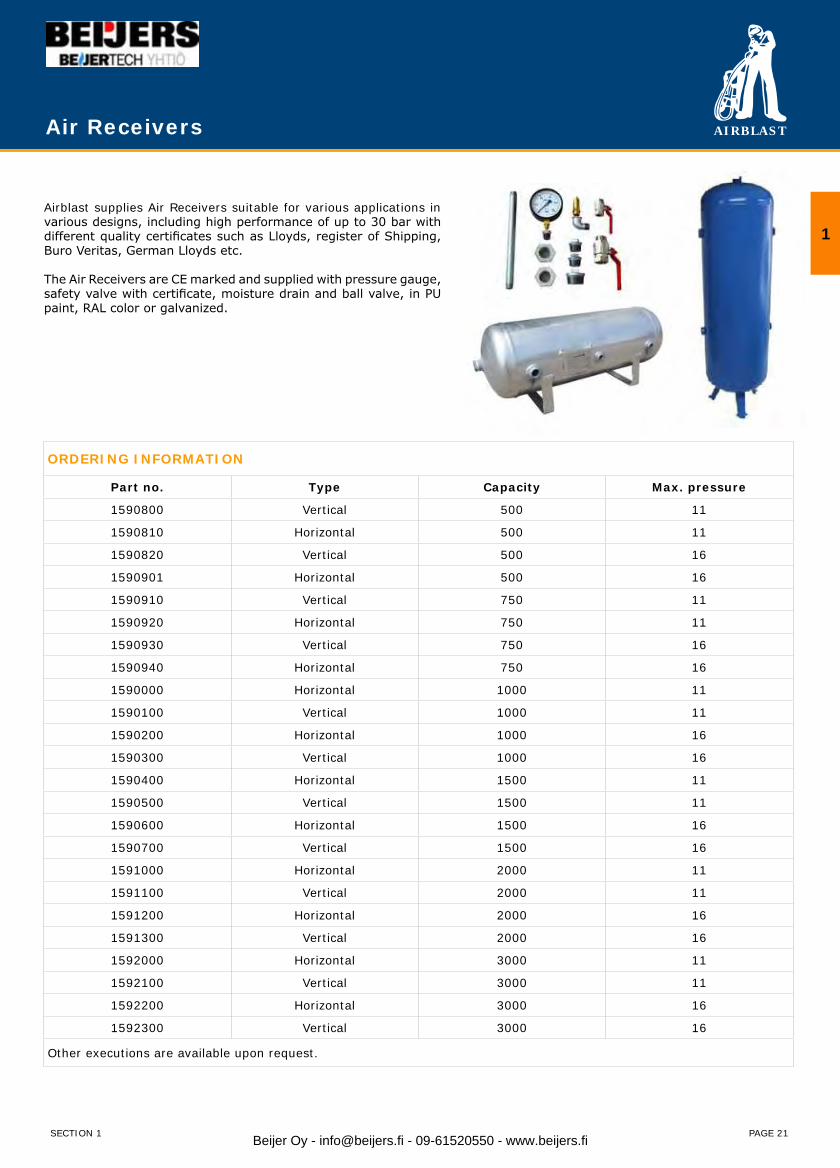
Air Receivers
Airblast supplies Air Receivers suitable for various applications in various designs, including high performance of up to 30 bar with different quality certificates such as Lloyds, register of Shipping, Buro Veritas, German Lloyds etc.
The Air Receivers are CE marked and supplied with pressure gauge, safety valve with certificate, moisture drain and ball valve, in PU paint, RAL color or galvanized.
ORDERING INFORMATION
Part no. Type Capacity Max. pressure
1590800 Vertical 500 11
1590810 Horizontal 500 11
1590820 Vertical 500 16
1590901 Horizontal 500 16
1590910 Vertical 750 11
1590920 Horizontal 750 11
1590930 Vertical 750 16
1590940 Horizontal 750 16
1590000 Horizontal 1000 11
1590100 Vertical 1000 11
1590200 Horizontal 1000 16
1590300 Vertical 1000 16
1590400 Horizontal 1500 11
1590500 Vertical 1500 11
1590600 Horizontal 1500 16
1590700 Vertical 1500 16
1591000 Horizontal 2000 11
1591100 Vertical 2000 11
1591200 Horizontal 2000 16
1591300 Vertical 2000 16
1592000 Horizontal 3000 11
1592100 Vertical 3000 11
1592200 Horizontal 3000 16
1592300 Vertical 3000 16
Other executions are available upon request.
1
SECTION 1 Beijer Oy - [email protected] - 09-61520550 - www.beijers.fi
AIRBLAST
PAGE 22
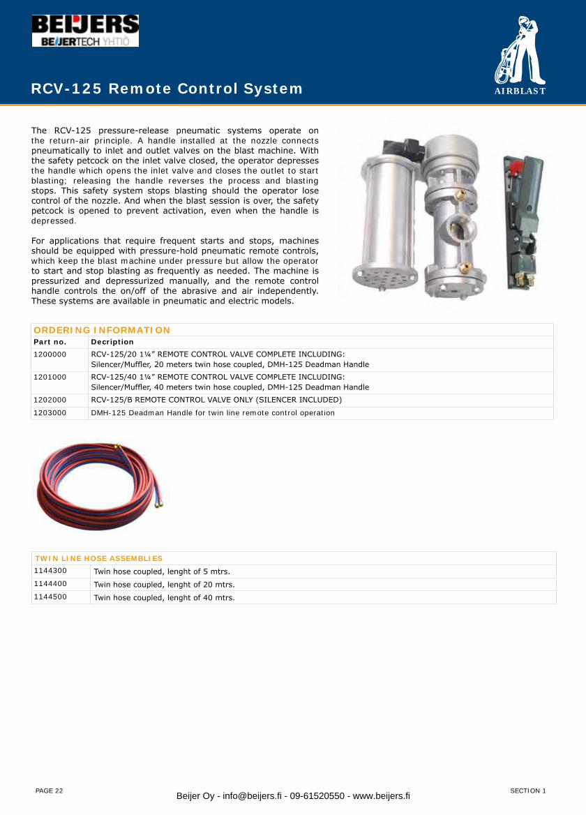
The RCV-125 pressure-release pneumatic systems operate on the return-air principle. A handle installed at the nozzle connects pneumatically to inlet and outlet valves on the blast machine. With the safety petcock on the inlet valve closed, the operator depresses the handle which opens the inlet valve and closes the outlet to start blasting; releasing the handle reverses the process and blasting stops. This safety system stops blasting should the operator lose control of the nozzle. And when the blast session is over, the safety petcock is opened to prevent activation, even when the handle is depressed.
For applications that require frequent starts and stops, machines should be equipped with pressure-hold pneumatic remote controls, which keep the blast machine under pressure but allow the operator to start and stop blasting as frequently as needed. The machine is pressurized and depressurized manually, and the remote control handle controls the on/off of the abrasive and air independently. These systems are available in pneumatic and electric models.
ORDERING INFORMATIONPart no. Decription1200000 RCV-125/20 1¼” REMOTE CONTROL VALVE COMPLETE INCLUDING:
Silencer/Muffler, 20 meters twin hose coupled, DMH-125 Deadman Handle1201000 RCV-125/40 1¼” REMOTE CONTROL VALVE COMPLETE INCLUDING:
Silencer/Muffler, 40 meters twin hose coupled, DMH-125 Deadman Handle
1202000 RCV-125/B REMOTE CONTROL VALVE ONLY (SILENCER INCLUDED)
1203000 DMH-125 Deadman Handle for twin line remote control operation
TWIN LINE HOSE ASSEMBLIES1144300 Twin hose coupled, lenght of 5 mtrs.1144400 Twin hose coupled, lenght of 20 mtrs.1144500 Twin hose coupled, lenght of 40 mtrs.
RCV-125 Remote Control System
SECTION 1Beijer Oy - [email protected] - 09-61520550 - www.beijers.fi
AIRBLAST
PAGE 23
RCV-125 Remote Control System
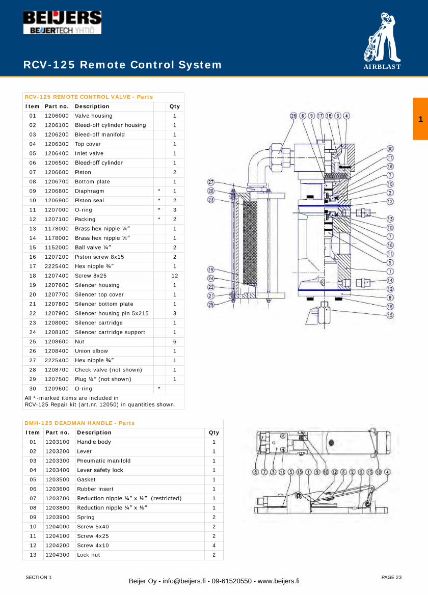
RCV-125 REMOTE CONTROL VALVE - Parts
Item Part no. Description Qty
01 1206000 Valve housing 1
02 1206100 Bleed-off cylinder housing 1
03 1206200 Bleed-off manifold 1
04 1206300 Top cover 1
05 1206400 Inlet valve 1
06 1206500 Bleed-off cylinder 1
07 1206600 Piston 2
08 1206700 Bottom plate 1
09 1206800 Diaphragm * 1
10 1206900 Piston seal * 2
11 1207000 O-ring * 3
12 1207100 Packing * 2
13 1178000 Brass hex nipple ¼” 1
14 1178000 Brass hex nipple ¼” 1
15 1152000 Ball valve ¼” 2
16 1207200 Piston screw 8x15 2
17 2225400 Hex nipple ¾” 1
18 1207400 Screw 8x25 12
19 1207600 Silencer housing 1
20 1207700 Silencer top cover 1
21 1207800 Silencer bottom plate 1
22 1207900 Silencer housing pin 5x215 3
23 1208000 Silencer cartridge 1
24 1208100 Silencer cartridge support 1
25 1208600 Nut 6
26 1208400 Union elbow 1
27 2225400 Hex nipple ¾” 1
28 1208700 Check valve (not shown) 1
29 1207500 Plug ¼” (not shown) 1
30 1209600 O-ring *
All *-marked items are included inRCV-125 Repair kit (art.nr. 12050) in quantities shown.
DMH-125 DEADMAN HANDLE - Parts
Item Part no. Description Qty
01 1203100 Handle body 1
02 1203200 Lever 1
03 1203300 Pneumatic manifold 1
04 1203400 Lever safety lock 1
05 1203500 Gasket 1
06 1203600 Rubber insert 1
07 1203700 Reduction nipple ¼” x ⅛” (restricted) 1
08 1203800 Reduction nipple ¼” x ⅛” 1
09 1203900 Spring 2
10 1204000 Screw 5x40 2
11 1204100 Screw 4x25 2
12 1204200 Screw 4x10 4
13 1204300 Lock nut 2
1
SECTION 1 Beijer Oy - [email protected] - 09-61520550 - www.beijers.fi
AIRBLAST
PAGE 24
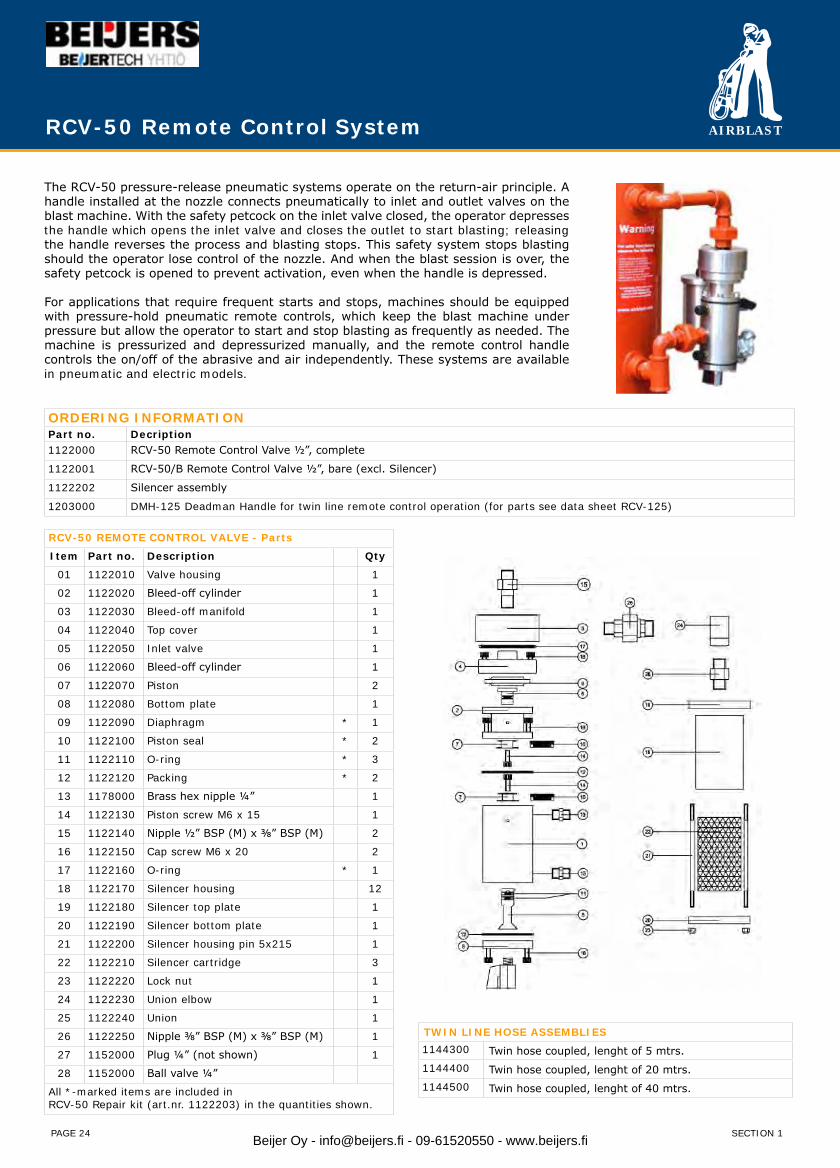
The RCV-50 pressure-release pneumatic systems operate on the return-air principle. A handle installed at the nozzle connects pneumatically to inlet and outlet valves on the blast machine. With the safety petcock on the inlet valve closed, the operator depresses the handle which opens the inlet valve and closes the outlet to start blasting; releasing the handle reverses the process and blasting stops. This safety system stops blasting should the operator lose control of the nozzle. And when the blast session is over, the safety petcock is opened to prevent activation, even when the handle is depressed.
For applications that require frequent starts and stops, machines should be equipped with pressure-hold pneumatic remote controls, which keep the blast machine under pressure but allow the operator to start and stop blasting as frequently as needed. The machine is pressurized and depressurized manually, and the remote control handle controls the on/off of the abrasive and air independently. These systems are available in pneumatic and electric models.
ORDERING INFORMATIONPart no. Decription1122000 RCV-50 Remote Control Valve ½”, complete
1122001 RCV-50/B Remote Control Valve ½”, bare (excl. Silencer)
1122202 Silencer assembly
1203000 DMH-125 Deadman Handle for twin line remote control operation (for parts see data sheet RCV-125)
RCV-50 REMOTE CONTROL VALVE - Parts
Item Part no. Description Qty
01 1122010 Valve housing 1
02 1122020 Bleed-off cylinder 1
03 1122030 Bleed-off manifold 1
04 1122040 Top cover 1
05 1122050 Inlet valve 1
06 1122060 Bleed-off cylinder 1
07 1122070 Piston 2
08 1122080 Bottom plate 1
09 1122090 Diaphragm * 1
10 1122100 Piston seal * 2
11 1122110 O-ring * 3
12 1122120 Packing * 2
13 1178000 Brass hex nipple ¼” 1
14 1122130 Piston screw M6 x 15 1
15 1122140 Nipple ½” BSP (M) x ⅜” BSP (M) 2
16 1122150 Cap screw M6 x 20 2
17 1122160 O-ring * 1
18 1122170 Silencer housing 12
19 1122180 Silencer top plate 1
20 1122190 Silencer bottom plate 1
21 1122200 Silencer housing pin 5x215 1
22 1122210 Silencer cartridge 3
23 1122220 Lock nut 1
24 1122230 Union elbow 1
25 1122240 Union 1
26 1122250 Nipple ⅜” BSP (M) x ⅜” BSP (M) 1
27 1152000 Plug ¼” (not shown) 1
28 1152000 Ball valve ¼”
All *-marked items are included inRCV-50 Repair kit (art.nr. 1122203) in the quantities shown.
TWIN LINE HOSE ASSEMBLIES1144300 Twin hose coupled, lenght of 5 mtrs.1144400 Twin hose coupled, lenght of 20 mtrs.1144500 Twin hose coupled, lenght of 40 mtrs.
RCV-50 Remote Control System
SECTION 1Beijer Oy - [email protected] - 09-61520550 - www.beijers.fi
AIRBLAST
PAGE 25
ACV - Airblast Combo Valve
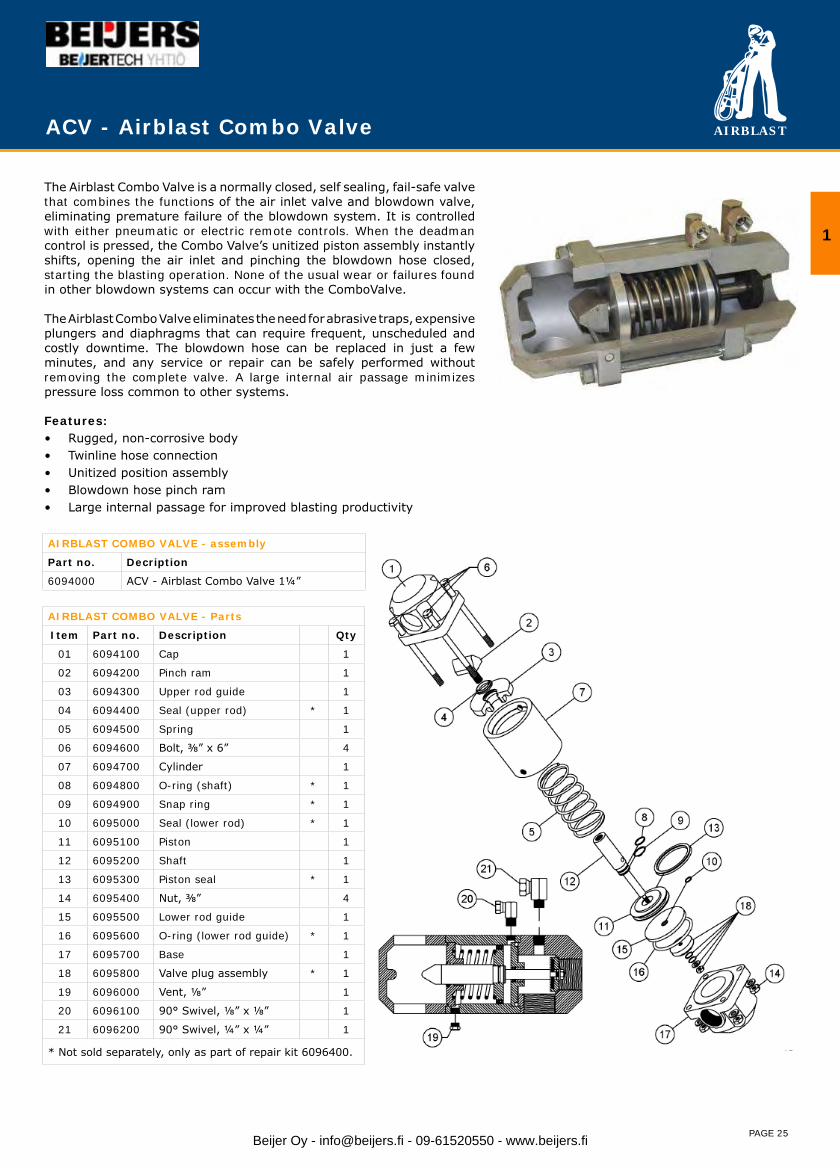
The Airblast Combo Valve is a normally closed, self sealing, fail-safe valve that combines the functions of the air inlet valve and blowdown valve, eliminating premature failure of the blowdown system. It is controlled with either pneumatic or electric remote controls. When the deadman control is pressed, the Combo Valve’s unitized piston assembly instantly shifts, opening the air inlet and pinching the blowdown hose closed, starting the blasting operation. None of the usual wear or failures found in other blowdown systems can occur with the ComboValve.
The Airblast Combo Valve eliminates the need for abrasive traps, expensive plungers and diaphragms that can require frequent, unscheduled and costly downtime. The blowdown hose can be replaced in just a few minutes, and any service or repair can be safely performed without removing the complete valve. A large internal air passage minimizes pressure loss common to other systems.
Features:• Rugged, non-corrosive body• Twinline hose connection• Unitized position assembly• Blowdown hose pinch ram• Large internal passage for improved blasting productivity
AIRBLAST COMBO VALVE - assembly
Part no. Decription
6094000 ACV - Airblast Combo Valve 1¼”
AIRBLAST COMBO VALVE - Parts
Item Part no. Description Qty
01 6094100 Cap 1
02 6094200 Pinch ram 1
03 6094300 Upper rod guide 1
04 6094400 Seal (upper rod) * 1
05 6094500 Spring 1
06 6094600 Bolt, ⅜” x 6” 4
07 6094700 Cylinder 1
08 6094800 O-ring (shaft) * 1
09 6094900 Snap ring * 1
10 6095000 Seal (lower rod) * 1
11 6095100 Piston 1
12 6095200 Shaft 1
13 6095300 Piston seal * 1
14 6095400 Nut, ⅜” 4
15 6095500 Lower rod guide 1
16 6095600 O-ring (lower rod guide) * 1
17 6095700 Base 1
18 6095800 Valve plug assembly * 1
19 6096000 Vent, ⅛” 1
20 6096100 90° Swivel, ⅛” x ⅛” 1
21 6096200 90° Swivel, ¼” x ¼” 1
* Not sold separately, only as part of repair kit 6096400.
1
Beijer Oy - [email protected] - 09-61520550 - www.beijers.fi

AIRBLAST
PAGE 26
Clearline Water Filter / Moisture Separator
Airblast blasting machines feature a highly efficient Clearline Moisture Separator.
The moisture separator prevents moisture and oil from the compressor entering the blast machine.
Often this is especially necessary when using old compressors, working at low temperatures or at a large distance from the compressor.
The Clearline Moisture Separator eliminates up to 98% of the condensate and oil from compressed air. This prevents the abrasive becoming damp and clogging the machine.
Available in the sizes ½” and 1½”.
CLEARLINE WATER FILTER / MOISTURE SEPARATOR
Part no. Description4056001 CLEARLINE ½” for use with 1028 blast machine with ½” piping.4057000 CLEARLINE 1½” with manual drain for use with blast machines with 1¼” piping.4058000 CLEARLINE 1½” AUTOMATIC with automatic drain for use with blast machines with 1¼” piping.
SPARE PARTS CLEARLINE 1½”
Part no. Description4057600 Bowl kit and sight glass, includes:
- Bowl- Sigh glass assembly- O-ring- Manual drain assembly
4058100 Automatic drain option4057300 40 micron filter4057400 Repair kit, includes:
- Baffle assembly- Deflector
SPARE PARTS CLEARLINE ½”
Part no. Description4056002 Metal bowl, sight glass and manual drain4056003 Particle filter element
SECTION 1Beijer Oy - [email protected] - 09-61520550 - www.beijers.fi
AIRBLAST
PAGE 27
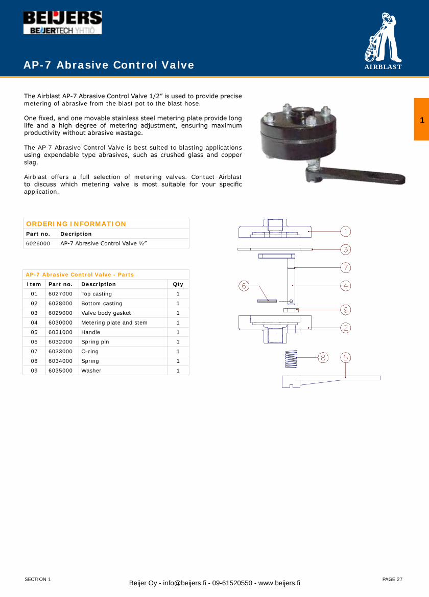
AP-7 Abrasive Control Valve
The Airblast AP-7 Abrasive Control Valve 1/2” is used to provide precise metering of abrasive from the blast pot to the blast hose.
One fixed, and one movable stainless steel metering plate provide long life and a high degree of metering adjustment, ensuring maximum productivity without abrasive wastage.
The AP-7 Abrasive Control Valve is best suited to blasting applications using expendable type abrasives, such as crushed glass and copper slag.
Airblast offers a full selection of metering valves. Contact Airblast to discuss which metering valve is most suitable for your specific application.
ORDERING INFORMATIONPart no. Decription
6026000 AP-7 Abrasive Control Valve ½”
AP-7 Abrasive Control Valve - Parts
Item Part no. Description Qty
01 6027000 Top casting 1
02 6028000 Bottom casting 1
03 6029000 Valve body gasket 1
04 6030000 Metering plate and stem 1
05 6031000 Handle 1
06 6032000 Spring pin 1
07 6033000 O-ring 1
08 6034000 Spring 1
09 6035000 Washer 1
SECTION 1
1
Beijer Oy - [email protected] - 09-61520550 - www.beijers.fi
AIRBLAST
PAGE 28
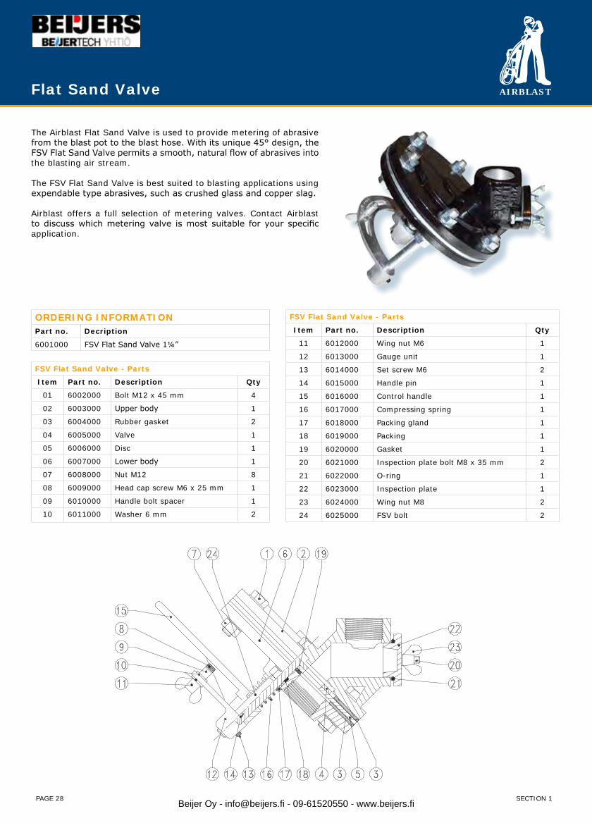
Flat Sand Valve
The Airblast Flat Sand Valve is used to provide metering of abrasive from the blast pot to the blast hose. With its unique 45° design, the FSV Flat Sand Valve permits a smooth, natural flow of abrasives into the blasting air stream.
The FSV Flat Sand Valve is best suited to blasting applications using expendable type abrasives, such as crushed glass and copper slag.
Airblast offers a full selection of metering valves. Contact Airblast to discuss which metering valve is most suitable for your specific application.
ORDERING INFORMATIONPart no. Decription
6001000 FSV Flat Sand Valve 1¼”
FSV Flat Sand Valve - Parts
Item Part no. Description Qty
11 6012000 Wing nut M6 1
12 6013000 Gauge unit 1
13 6014000 Set screw M6 2
14 6015000 Handle pin 1
15 6016000 Control handle 1
16 6017000 Compressing spring 1
17 6018000 Packing gland 1
18 6019000 Packing 1
19 6020000 Gasket 1
20 6021000 Inspection plate bolt M8 x 35 mm 2
21 6022000 O-ring 1
22 6023000 Inspection plate 1
23 6024000 Wing nut M8 2
24 6025000 FSV bolt 2
FSV Flat Sand Valve - Parts
Item Part no. Description Qty
01 6002000 Bolt M12 x 45 mm 4
02 6003000 Upper body 1
03 6004000 Rubber gasket 2
04 6005000 Valve 1
05 6006000 Disc 1
06 6007000 Lower body 1
07 6008000 Nut M12 8
08 6009000 Head cap screw M6 x 25 mm 1
09 6010000 Handle bolt spacer 1
10 6011000 Washer 6 mm 2
SECTION 1Beijer Oy - [email protected] - 09-61520550 - www.beijers.fi
AIRBLAST
PAGE 29
SGV Steel Grit Valve
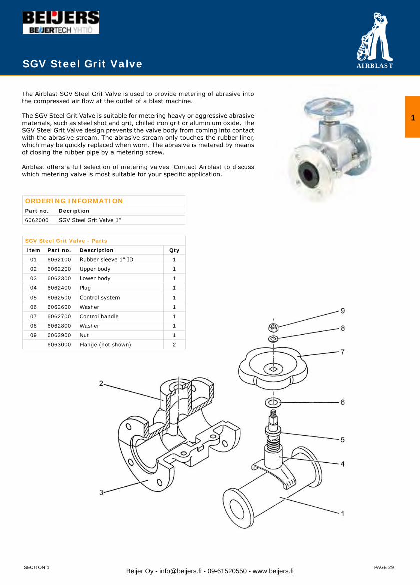
The Airblast SGV Steel Grit Valve is used to provide metering of abrasive into the compressed air flow at the outlet of a blast machine.
The SGV Steel Grit Valve is suitable for metering heavy or aggressive abrasive materials, such as steel shot and grit, chilled iron grit or aluminium oxide. The SGV Steel Grit Valve design prevents the valve body from coming into contact with the abrasive stream. The abrasive stream only touches the rubber liner, which may be quickly replaced when worn. The abrasive is metered by means of closing the rubber pipe by a metering screw.
Airblast offers a full selection of metering valves. Contact Airblast to discuss which metering valve is most suitable for your specific application.
ORDERING INFORMATIONPart no. Decription
6062000 SGV Steel Grit Valve 1”
SGV Steel Grit Valve - Parts
Item Part no. Description Qty
01 6062100 Rubber sleeve 1” ID 1
02 6062200 Upper body 1
03 6062300 Lower body 1
04 6062400 Plug 1
05 6062500 Control system 1
06 6062600 Washer 1
07 6062700 Control handle 1
08 6062800 Washer 1
09 6062900 Nut 1
6063000 Flange (not shown) 2
SECTION 1
1
Beijer Oy - [email protected] - 09-61520550 - www.beijers.fi
AIRBLAST
PAGE 30
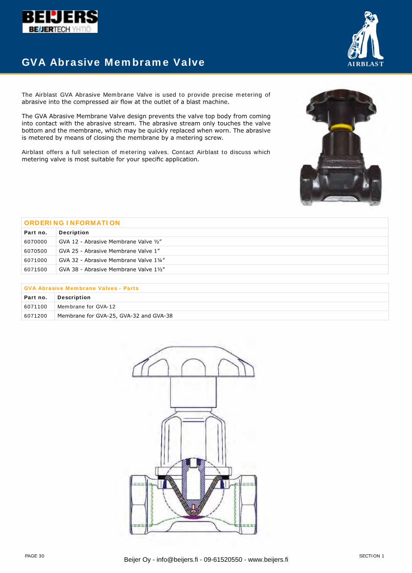
The Airblast GVA Abrasive Membrane Valve is used to provide precise metering of abrasive into the compressed air flow at the outlet of a blast machine.
The GVA Abrasive Membrane Valve design prevents the valve top body from coming into contact with the abrasive stream. The abrasive stream only touches the valve bottom and the membrane, which may be quickly replaced when worn. The abrasive is metered by means of closing the membrane by a metering screw.
Airblast offers a full selection of metering valves. Contact Airblast to discuss which metering valve is most suitable for your specific application.
ORDERING INFORMATIONPart no. Decription
6070000 GVA 12 - Abrasive Membrane Valve ½”
6070500 GVA 25 - Abrasive Membrane Valve 1”
6071000 GVA 32 - Abrasive Membrane Valve 1¼”
6071500 GVA 38 - Abrasive Membrane Valve 1½”
GVA Abrasive Membrane Valves - Parts
Part no. Description
6071100 Membrane for GVA-12
6071200 Membrane for GVA-25, GVA-32 and GVA-38
GVA Abrasive Membrame Valve
SECTION 1Beijer Oy - [email protected] - 09-61520550 - www.beijers.fi
AIRBLAST
PAGE 31
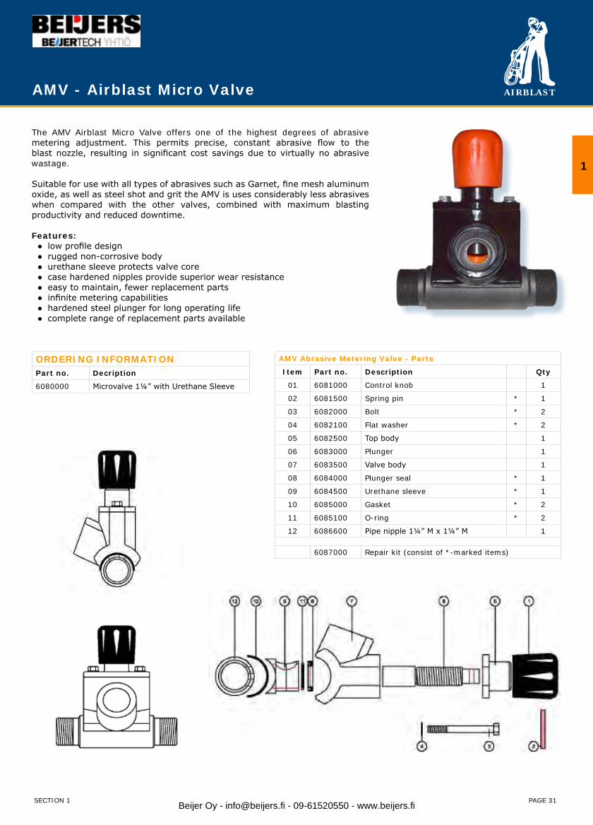
AMV - Airblast Micro Valve
The AMV Airblast Micro Valve offers one of the highest degrees of abrasive metering adjustment. This permits precise, constant abrasive flow to the blast nozzle, resulting in significant cost savings due to virtually no abrasive wastage.
Suitable for use with all types of abrasives such as Garnet, fine mesh aluminum oxide, as well as steel shot and grit the AMV is uses considerably less abrasives when compared with the other valves, combined with maximum blasting productivity and reduced downtime.
Features: ● low profile design ● rugged non-corrosive body ● urethane sleeve protects valve core ● case hardened nipples provide superior wear resistance ● easy to maintain, fewer replacement parts ● infinite metering capabilities ● hardened steel plunger for long operating life ● complete range of replacement parts available
ORDERING INFORMATIONPart no. Decription
6080000 Microvalve 1¼” with Urethane Sleeve
AMV Abrasive Metering Valve - Parts
Item Part no. Description Qty
01 6081000 Control knob 1
02 6081500 Spring pin * 1
03 6082000 Bolt * 2
04 6082100 Flat washer * 2
05 6082500 Top body 1
06 6083000 Plunger 1
07 6083500 Valve body 1
08 6084000 Plunger seal * 1
09 6084500 Urethane sleeve * 1
10 6085000 Gasket * 2
11 6085100 O-ring * 2
12 6086600 Pipe nipple 1¼” M x 1¼” M 1
6087000 Repair kit (consist of *-marked items)
SECTION 1
1
Beijer Oy - [email protected] - 09-61520550 - www.beijers.fi

AIRBLAST
PAGE 32
Thompson Valve
The original Thompson Valve is a normally closed, self sealing, abrasive metering valve known for its instant, smooth response to either pneumatic or electric deadman controls. This fail-safe valve shuts off abrasive flow to the nozzle and seals the tank at the same instant. A remote abrasive cutoff is available, allowing the operator to stop the flow of media while continuing a constant flow of air. This provides a quick and easy way to clear the blast hose and blasting area of abrasive.
Designed for superior operator safety, the Thompson Valve is ideal for multiple outlet use and is easily adaptable to most existing blasting systems. It is engineered to allow precise metering of all types of abrasive media and can be modified for special applications.
FeaturesOne knob precisely controls abrasive flow• Standard urethane sleeve for normal operation, or optional tungsten carbide • sleeve for extended life Design minimizes air turbulence in mixing chamber, providing even media flow• A short path helps ensure constant abrasive media flow• Orifice is sized for precise metering of abrasive• Rugged, non-corrosive body•
ORDERING INFORMATIONPart no. Decription
6088000 Thompson Valve 1” with Tungsten Carbide sleeve
6088500 Thompson Valve 1” with Urethane sleeve
6089000 Thompson Valve 1¼” with Tungsten Carbide sleeve
6089500 Thompson Valve 1¼” with Urethane sleeve
6090000 Thompson Valve 1½” with Tungsten Carbide sleeve
6090500 Thompson Valve 1½” with Urethane sleeve
SECTION 1
THOMPSON VALVE Abrasive Metering Valve - Parts
Item Part no. Description TC U Qty
01 6091000 Control knob 1
02 6091100 Cap 1
03 6091200 Bump ring 1
04 6091300 Spring 2
05 6091400 Nut 1
06 6091500 Piston seal * ** 1
07 6091600 Piston 1
08 6091700 Tungsten Carbide Plunger * ** 1
09 6091800 Cylinder 1
10 6091900 Plunger seal * ** 1
11a 6092900 Tungsten Carbide Sleeve * 1
11b 6092000 Urethane sleeve ** 1
12 6092100 Base 1
13 6092200 Bolt 2
14a 6092300 Pipe nipple 1” M x 1” M 1
14b 6092400 Pipe nipple 1¼” M x 1¼” M 1
14c 6092500 Pipe nipple 1½” M x 1½” M 1
15 6092600 Sleeve pin 1
6093000 Repair kit for TC sleeve, consist of *-marked items
6093100 Repair kit for U sleeve, consist of **-marked items
Beijer Oy - [email protected] - 09-61520550 - www.beijers.fi
AIRBLAST
PAGE 33
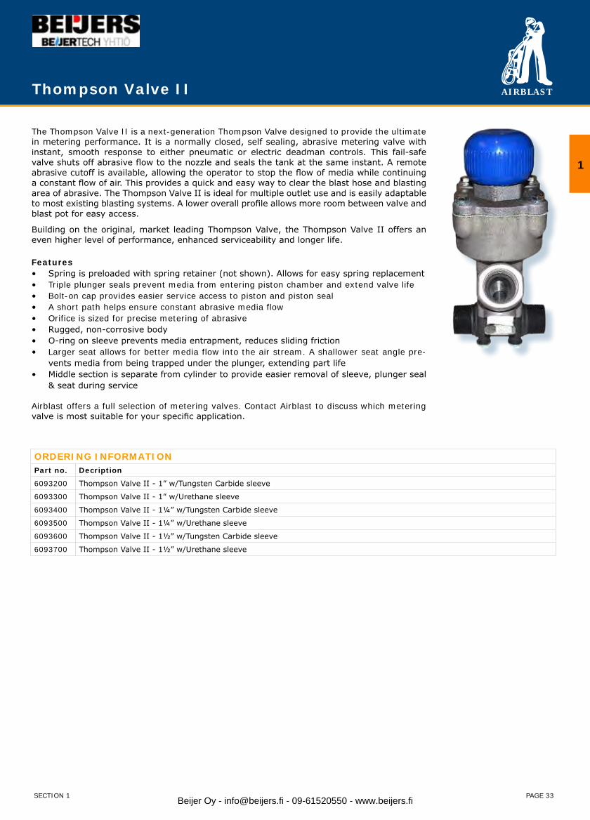
Thompson Valve II
The Thompson Valve II is a next-generation Thompson Valve designed to provide the ultimate in metering performance. It is a normally closed, self sealing, abrasive metering valve with instant, smooth response to either pneumatic or electric deadman controls. This fail-safe valve shuts off abrasive flow to the nozzle and seals the tank at the same instant. A remote abrasive cutoff is available, allowing the operator to stop the flow of media while continuing a constant flow of air. This provides a quick and easy way to clear the blast hose and blasting area of abrasive. The Thompson Valve II is ideal for multiple outlet use and is easily adaptable to most existing blasting systems. A lower overall profile allows more room between valve and blast pot for easy access.
Building on the original, market leading Thompson Valve, the Thompson Valve II offers an even higher level of performance, enhanced serviceability and longer life.
FeaturesSpring is preloaded with spring retainer (not shown). Allows for easy spring replacement• Triple plunger seals prevent media from entering piston chamber and extend valve life • Bolt-on cap provides easier service access to piston and piston seal• A short path helps ensure constant abrasive media flow• Orifice is sized for precise metering of abrasive• Rugged, non-corrosive body• O-ring on sleeve prevents media entrapment, reduces sliding friction• Larger seat allows for better media flow into the air stream. A shallower seat angle pre-• vents media from being trapped under the plunger, extending part lifeMiddle section is separate from cylinder to provide easier removal of sleeve, plunger seal • & seat during service
Airblast offers a full selection of metering valves. Contact Airblast to discuss which metering valve is most suitable for your specific application.
ORDERING INFORMATIONPart no. Decription
6093200 Thompson Valve II - 1” w/Tungsten Carbide sleeve
6093300 Thompson Valve II - 1” w/Urethane sleeve
6093400 Thompson Valve II - 1¼” w/Tungsten Carbide sleeve
6093500 Thompson Valve II - 1¼” w/Urethane sleeve
6093600 Thompson Valve II - 1½” w/Tungsten Carbide sleeve
6093700 Thompson Valve II - 1½” w/Urethane sleeve
SECTION 1
1
Beijer Oy - [email protected] - 09-61520550 - www.beijers.fi
AIRBLAST
PAGE 34
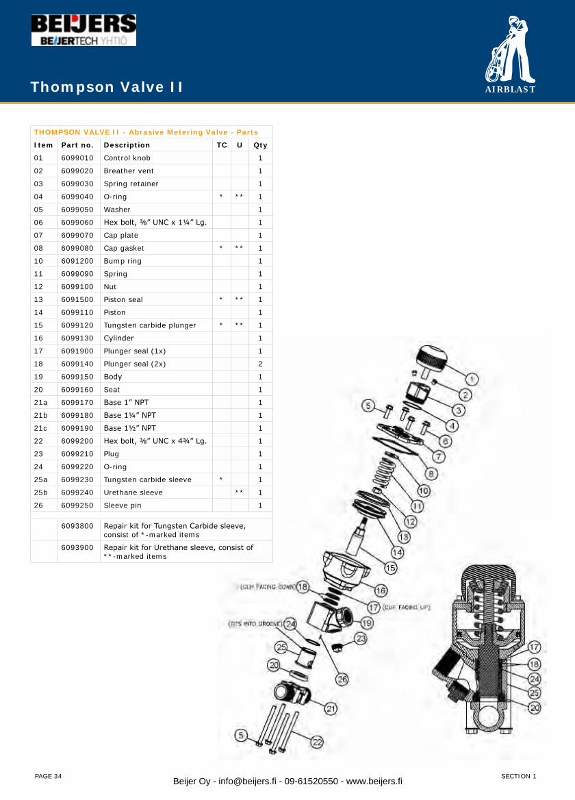
THOMPSON VALVE II - Abrasive Metering Valve - Parts
Item Part no. Description TC U Qty
01 6099010 Control knob 1
02 6099020 Breather vent 1
03 6099030 Spring retainer 1
04 6099040 O-ring * ** 1
05 6099050 Washer 1
06 6099060 Hex bolt, ⅜” UNC x 1¼” Lg. 1
07 6099070 Cap plate 1
08 6099080 Cap gasket * ** 1
10 6091200 Bump ring 1
11 6099090 Spring 1
12 6099100 Nut 1
13 6091500 Piston seal * ** 1
14 6099110 Piston 1
15 6099120 Tungsten carbide plunger * ** 1
16 6099130 Cylinder 1
17 6091900 Plunger seal (1x) 1
18 6099140 Plunger seal (2x) 2
19 6099150 Body 1
20 6099160 Seat 1
21a 6099170 Base 1” NPT 1
21b 6099180 Base 1¼” NPT 1
21c 6099190 Base 1½” NPT 1
22 6099200 Hex bolt, ⅜” UNC x 4¾” Lg. 1
23 6099210 Plug 1
24 6099220 O-ring 1
25a 6099230 Tungsten carbide sleeve * 1
25b 6099240 Urethane sleeve ** 1
26 6099250 Sleeve pin 1
6093800 Repair kit for Tungsten Carbide sleeve,consist of *-marked items
6093900 Repair kit for Urethane sleeve, consist of**-marked items
Thompson Valve II
SECTION 1Beijer Oy - [email protected] - 09-61520550 - www.beijers.fi
AIRBLAST
PAGE 35
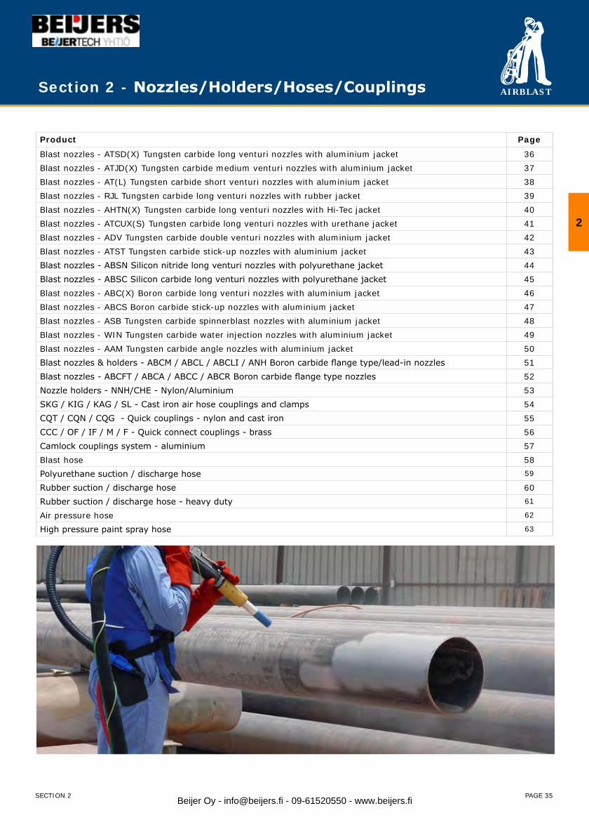
Section 2 - Nozzles/Holders/Hoses/Couplings
Product Page
Blast nozzles - ATSD(X) Tungsten carbide long venturi nozzles with aluminium jacket 36Blast nozzles - ATJD(X) Tungsten carbide medium venturi nozzles with aluminium jacket 37Blast nozzles - AT(L) Tungsten carbide short venturi nozzles with aluminium jacket 38Blast nozzles - RJL Tungsten carbide long venturi nozzles with rubber jacket 39Blast nozzles - AHTN(X) Tungsten carbide long venturi nozzles with Hi-Tec jacket 40Blast nozzles - ATCUX(S) Tungsten carbide long venturi nozzles with urethane jacket 41Blast nozzles - ADV Tungsten carbide double venturi nozzles with aluminium jacket 42Blast nozzles - ATST Tungsten carbide stick-up nozzles with aluminium jacket 43Blast nozzles - ABSN Silicon nitride long venturi nozzles with polyurethane jacket 44Blast nozzles - ABSC Silicon carbide long venturi nozzles with polyurethane jacket 45Blast nozzles - ABC(X) Boron carbide long venturi nozzles with aluminium jacket 46Blast nozzles - ABCS Boron carbide stick-up nozzles with aluminium jacket 47Blast nozzles - ASB Tungsten carbide spinnerblast nozzles with aluminium jacket 48Blast nozzles - WIN Tungsten carbide water injection nozzles with aluminium jacket 49Blast nozzles - AAM Tungsten carbide angle nozzles with aluminium jacket 50Blast nozzles & holders - ABCM / ABCL / ABCLI / ANH Boron carbide flange type/lead-in nozzles 51Blast nozzles - ABCFT / ABCA / ABCC / ABCR Boron carbide flange type nozzles 52Nozzle holders - NNH/CHE - Nylon/Aluminium 53SKG / KIG / KAG / SL - Cast iron air hose couplings and clamps 54CQT / CQN / CQG - Quick couplings - nylon and cast iron 55CCC / OF / IF / M / F - Quick connect couplings - brass 56Camlock couplings system - aluminium 57Blast hose 58Polyurethane suction / discharge hose 59
Rubber suction / discharge hose 60Rubber suction / discharge hose - heavy duty 61
Air pressure hose 62
High pressure paint spray hose 63
2
SECTION 2 Beijer Oy - [email protected] - 09-61520550 - www.beijers.fi
AIRBLAST
PAGE 36
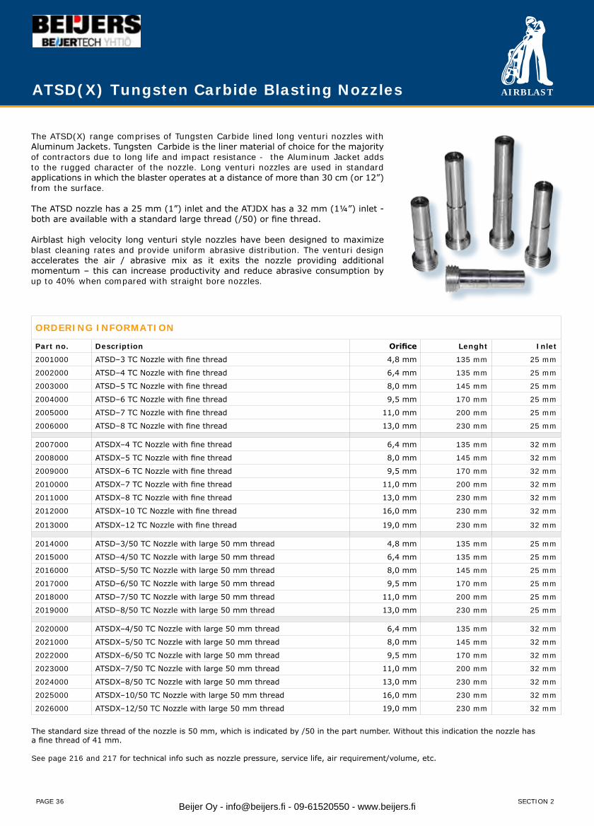
ATSD(X) Tungsten Carbide Blasting Nozzles
ORDERING INFORMATION
Part no. Description Orifice Lenght Inlet
2001000 ATSD–3 TC Nozzle with fine thread 4,8 mm 135 mm 25 mm
2002000 ATSD–4 TC Nozzle with fine thread 6,4 mm 135 mm 25 mm
2003000 ATSD–5 TC Nozzle with fine thread 8,0 mm 145 mm 25 mm
2004000 ATSD–6 TC Nozzle with fine thread 9,5 mm 170 mm 25 mm
2005000 ATSD–7 TC Nozzle with fine thread 11,0 mm 200 mm 25 mm
2006000 ATSD–8 TC Nozzle with fine thread 13,0 mm 230 mm 25 mm
2007000 ATSDX–4 TC Nozzle with fine thread 6,4 mm 135 mm 32 mm
2008000 ATSDX–5 TC Nozzle with fine thread 8,0 mm 145 mm 32 mm
2009000 ATSDX–6 TC Nozzle with fine thread 9,5 mm 170 mm 32 mm
2010000 ATSDX–7 TC Nozzle with fine thread 11,0 mm 200 mm 32 mm
2011000 ATSDX–8 TC Nozzle with fine thread 13,0 mm 230 mm 32 mm
2012000 ATSDX–10 TC Nozzle with fine thread 16,0 mm 230 mm 32 mm
2013000 ATSDX–12 TC Nozzle with fine thread 19,0 mm 230 mm 32 mm
2014000 ATSD–3/50 TC Nozzle with large 50 mm thread 4,8 mm 135 mm 25 mm
2015000 ATSD–4/50 TC Nozzle with large 50 mm thread 6,4 mm 135 mm 25 mm
2016000 ATSD–5/50 TC Nozzle with large 50 mm thread 8,0 mm 145 mm 25 mm
2017000 ATSD–6/50 TC Nozzle with large 50 mm thread 9,5 mm 170 mm 25 mm
2018000 ATSD–7/50 TC Nozzle with large 50 mm thread 11,0 mm 200 mm 25 mm
2019000 ATSD–8/50 TC Nozzle with large 50 mm thread 13,0 mm 230 mm 25 mm
2020000 ATSDX–4/50 TC Nozzle with large 50 mm thread 6,4 mm 135 mm 32 mm
2021000 ATSDX–5/50 TC Nozzle with large 50 mm thread 8,0 mm 145 mm 32 mm
2022000 ATSDX–6/50 TC Nozzle with large 50 mm thread 9,5 mm 170 mm 32 mm
2023000 ATSDX–7/50 TC Nozzle with large 50 mm thread 11,0 mm 200 mm 32 mm
2024000 ATSDX–8/50 TC Nozzle with large 50 mm thread 13,0 mm 230 mm 32 mm
2025000 ATSDX–10/50 TC Nozzle with large 50 mm thread 16,0 mm 230 mm 32 mm
2026000 ATSDX–12/50 TC Nozzle with large 50 mm thread 19,0 mm 230 mm 32 mm
The standard size thread of the nozzle is 50 mm, which is indicated by /50 in the part number. Without this indication the nozzle has a fine thread of 41 mm.
See page 216 and 217 for technical info such as nozzle pressure, service life, air requirement/volume, etc.
The ATSD(X) range comprises of Tungsten Carbide lined long venturi nozzles with Aluminum Jackets. Tungsten Carbide is the liner material of choice for the majority of contractors due to long life and impact resistance - the Aluminum Jacket adds to the rugged character of the nozzle. Long venturi nozzles are used in standard applications in which the blaster operates at a distance of more than 30 cm (or 12”) from the surface.
The ATSD nozzle has a 25 mm (1”) inlet and the ATJDX has a 32 mm (1¼”) inlet - both are available with a standard large thread (/50) or fine thread.
Airblast high velocity long venturi style nozzles have been designed to maximize blast cleaning rates and provide uniform abrasive distribution. The venturi design accelerates the air / abrasive mix as it exits the nozzle providing additional momentum – this can increase productivity and reduce abrasive consumption by up to 40% when compared with straight bore nozzles.
SECTION 2Beijer Oy - [email protected] - 09-61520550 - www.beijers.fi

AIRBLAST
PAGE 37
ATJD(X) Tungsten Carbide Medium Blasting Nozzles
The ATJD(X) range comprises of Tungsten Carbide lined medium venturi nozzles with Aluminum Jackets. Tungsten Carbide is the liner material of choice for the majority of contractors due to long life and impact resistance - the Aluminum Jacket adds to the rugged character of the nozzle. Medium venturi nozzles are mainly used in applications in which the blasting is conducted in a confined space - therefore the blaster will normally operate at a distance of less than 30 cm (12”) from the surface.
The ATJD nozzle has a 25 mm (1”) inlet and the ATJDX has a 32 mm (1¼”) inlet - both are available with a standard large thread (/50) or fine thread.
Airblast high velocity venturi style nozzles have been designed to maximize blast cleaning rates and provide uniform abrasive distribution. The venturi design accelerates the air / abrasive mix as it exits the nozzle providing additional momentum – this can increase productivity and reduce abrasive consumption by up to 40% when compared with straight bore nozzles.
ORDERING INFORMATION
Part no. Description Orifice Lenght Inlet
2027000 ATJD-3 TC Nozzle with fine thread 4,8 mm 85 mm 25 mm
2028000 ATJD-4 TC Nozzle with fine thread 6,4 mm 85 mm 25 mm
2029000 ATJD-5 TC Nozzle with fine thread 8,0 mm 85 mm 25 mm
2030000 ATJD-6 TC Nozzle with fine thread 9,5 mm 85 mm 25 mm
2031000 ATJD-7 TC Nozzle with fine thread 11,0 mm 85 mm 25 mm
2032000 ATJD-8 TC Nozzle with fine thread 13.0 mm 85 mm 25 mm
2032900 ATJDX-4 TC Nozzle with fine thread 6,4 mm 85 mm 32 mm
2033000 ATJDX-5 TC Nozzle with fine thread 8,0 mm 85 mm 32 mm
2034000 ATJDX-6 TC Nozzle with fine thread 9,5 mm 85 mm 32 mm
2035000 ATJDX-7 TC Nozzle with fine thread 11,0 mm 85 mm 32 mm
2036000 ATJDX-8 TC Nozzle with fine thread 13.0 mm 85 mm 32 mm
2037000 ATJDX-10 TC Nozzle with fine thread 16.0 mm 85 mm 32 mm
2038000 ATJD-3/50 TC Nozzle with large 50 mm thread 4,8 mm 85 mm 25 mm
2039000 ATJD-4/50 TC Nozzle with large 50 mm thread 6,4 mm 85 mm 25 mm
2040000 ATJD-5/50 TC Nozzle with large 50 mm thread 8,0 mm 85 mm 25 mm
2041000 ATJD-6/50 TC Nozzle with large 50 mm thread 9,5 mm 85 mm 25 mm
2042000 ATJD-7/50 TC Nozzle with large 50 mm thread 11,0 mm 85 mm 25 mm
2043000 ATJD-8/50 TC Nozzle with large 50 mm thread 13.0 mm 85 mm 25 mm
2043900 ATJDX–4/50 TC Nozzle with large 50 mm thread 6,4 mm 85 mm 32 mm
2044000 ATJDX–5/50 TC Nozzle with large 50 mm thread 8,0 mm 85 mm 32 mm
2045000 ATJDX–6/50 TC Nozzle with large 50 mm thread 9,5 mm 85 mm 32 mm
2046000 ATJDX–7/50 TC Nozzle with large 50 mm thread 11,0 mm 85 mm 32 mm
2047000 ATJDX–8/50 TC Nozzle with large 50 mm thread 13.0 mm 85 mm 32 mm
2048000 ATJDX-10/50 TC Nozzle with large 50 mm thread 16.0 mm 85 mm 32 mm
The standard size thread of the nozzle is 50 mm, which is indicated by /50 in the part number. Without this indication the nozzle has a fine thread of 41 mm.
See page 216 and 217 for technical info such as nozzle pressure, service life, air requirement/volume, etc.
SECTION 2
2
Beijer Oy - [email protected] - 09-61520550 - www.beijers.fi
AIRBLAST
PAGE 38
ORDERING INFORMATION
Part no. Description Orifice Lenght Inlet
2085000 AT-2 TC Nozzle with fine 26 mm thread 3,2 mm 45 mm 13 mm
2086000 AT-3 TC Nozzle with fine 26 mm thread 4,8 mm 45 mm 13 mm
2087000 AT-4 TC Nozzle with fine 26 mm thread 6,5 mm 45 mm 13 mm
2088000 AT-5 TC Nozzle with fine 26 mm thread 8,0 mm 45 mm 13 mm
2089000 AT-6 TC Nozzle with fine 26 mm thread 9,5 mm 45 mm 13 mm
2090000 AT-8 TC Nozzle with fine 26 mm thread 13,0 mm 45 mm 13 mm
2085100 ATL-2 TC Nozzle with large 28 mm thread 3,2 mm 45 mm 13 mm
2086100 ATL-3 TC Nozzle with large 28 mm thread 4,8 mm 45 mm 13 mm
2087100 ATL-4 TC Nozzle with large 28 mm thread 6,5 mm 45 mm 13 mm
2088100 ATL-5 TC Nozzle with large 28 mm thread 8,0 mm 45 mm 13 mm
2089100 ATL-6 TC Nozzle with large 28 mm thread 9,5 mm 45 mm 13 mm
2090100 ATL-8 TC Nozzle with large 28 mm thread 13,0 mm 45 mm 13 mm
See page 216 and 217 for technical info such as nozzle pressure, service life, air requirement/volume, etc.
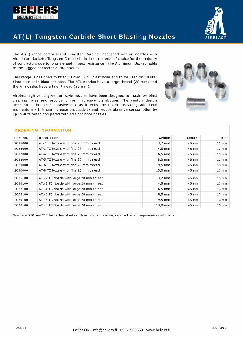
The AT(L) range comprises of Tungsten Carbide lined short venturi nozzles with Aluminium Jackets. Tungsten Carbide is the liner material of choice for the majority of contractors due to long life and impact resistance - the Aluminium Jacket (adds to the rugged character of the nozzle).
This range is designed to fit to 13 mm (½”) blast hose and to be used on 18 liter blast pots or in blast cabinets. The ATL nozzles have a large thread (28 mm) and the AT nozzles have a finer thread (26 mm).
Airblast high velocity venturi style nozzles have been designed to maximize blast cleaning rates and provide uniform abrasive distribution. The venturi design accelerates the air / abrasive mix as it exits the nozzle providing additional momentum – this can increase productivity and reduce abrasive consumption by up to 40% when compared with straight bore nozzles.
AT(L) Tungsten Carbide Short Blasting Nozzles
SECTION 2Beijer Oy - [email protected] - 09-61520550 - www.beijers.fi
AIRBLAST
PAGE 39
RJL Tungsten Carbide Blasting Nozzles
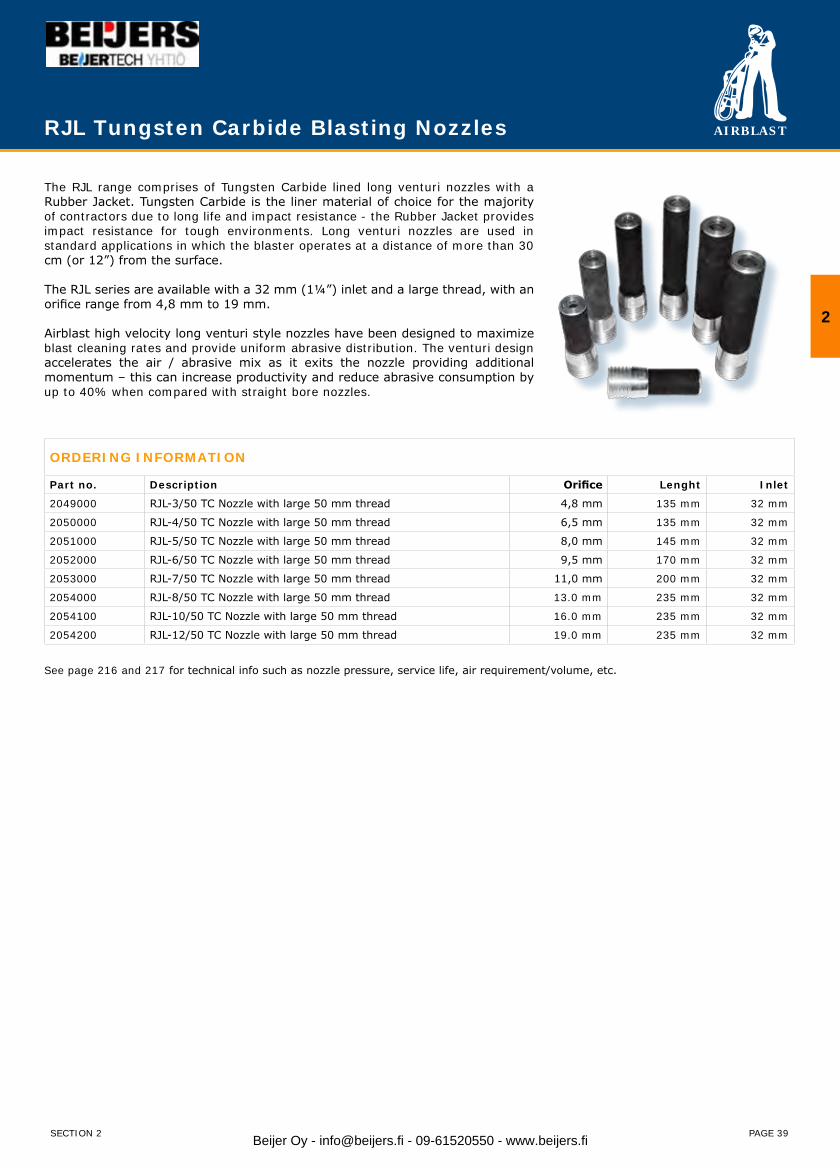
The RJL range comprises of Tungsten Carbide lined long venturi nozzles with a Rubber Jacket. Tungsten Carbide is the liner material of choice for the majority of contractors due to long life and impact resistance - the Rubber Jacket provides impact resistance for tough environments. Long venturi nozzles are used in standard applications in which the blaster operates at a distance of more than 30 cm (or 12”) from the surface. The RJL series are available with a 32 mm (1¼”) inlet and a large thread, with an orifice range from 4,8 mm to 19 mm.
Airblast high velocity long venturi style nozzles have been designed to maximize blast cleaning rates and provide uniform abrasive distribution. The venturi design accelerates the air / abrasive mix as it exits the nozzle providing additional momentum – this can increase productivity and reduce abrasive consumption by up to 40% when compared with straight bore nozzles.
ORDERING INFORMATION
Part no. Description Orifice Lenght Inlet
2049000 RJL-3/50 TC Nozzle with large 50 mm thread 4,8 mm 135 mm 32 mm
2050000 RJL-4/50 TC Nozzle with large 50 mm thread 6,5 mm 135 mm 32 mm
2051000 RJL-5/50 TC Nozzle with large 50 mm thread 8,0 mm 145 mm 32 mm
2052000 RJL-6/50 TC Nozzle with large 50 mm thread 9,5 mm 170 mm 32 mm
2053000 RJL-7/50 TC Nozzle with large 50 mm thread 11,0 mm 200 mm 32 mm
2054000 RJL-8/50 TC Nozzle with large 50 mm thread 13.0 mm 235 mm 32 mm
2054100 RJL-10/50 TC Nozzle with large 50 mm thread 16.0 mm 235 mm 32 mm
2054200 RJL-12/50 TC Nozzle with large 50 mm thread 19.0 mm 235 mm 32 mm
See page 216 and 217 for technical info such as nozzle pressure, service life, air requirement/volume, etc.
2
SECTION 2 Beijer Oy - [email protected] - 09-61520550 - www.beijers.fi
AIRBLAST
PAGE 40
AHTN(X) Tungsten Carbide Blasting Nozzles
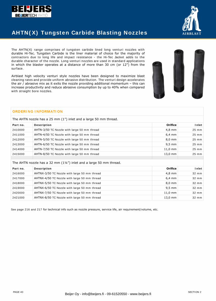
The AHTN(X) range comprises of tungsten carbide lined long venturi nozzles with durable Hi-Tec. Tungsten Carbide is the liner material of choice for the majority of contractors due to long life and impact resistance - the Hi-Tec Jacket adds to the durable character of the nozzle. Long venturi nozzles are used in standard applications in which the blaster operates at a distance of more than 30 cm (or 12”) from the surface.
Airblast high velocity venturi style nozzles have been designed to maximize blast cleaning rates and provide uniform abrasive distribution. The venturi design accelerates the air / abrasive mix as it exits the nozzle providing additional momentum – this can increase productivity and reduce abrasive consumption by up to 40% when compared with straight bore nozzles.
ORDERING INFORMATION
The AHTN nozzle has a 25 mm (1”) inlet and a large 50 mm thread.
Part no. Description Orifice Inlet
2410000 AHTN-3/50 TC Nozzle with large 50 mm thread 4,8 mm 25 mm
2411000 AHTN-4/50 TC Nozzle with large 50 mm thread 6,4 mm 25 mm
2412000 AHTN-5/50 TC Nozzle with large 50 mm thread 8,0 mm 25 mm
2413000 AHTN-6/50 TC Nozzle with large 50 mm thread 9,5 mm 25 mm
2414000 AHTN-7/50 TC Nozzle with large 50 mm thread 11,0 mm 25 mm
2415000 AHTN-8/50 TC Nozzle with large 50 mm thread 13,0 mm 25 mm
The AHTN nozzle has a 32 mm (1¼”) inlet and a large 50 mm thread.
Part no. Description Orifice Inlet
2416000 AHTNX-3/50 TC Nozzle with large 50 mm thread 4,8 mm 32 mm
2417000 AHTNX-4/50 TC Nozzle with large 50 mm thread 6,4 mm 32 mm
2418000 AHTNX-5/50 TC Nozzle with large 50 mm thread 8,0 mm 32 mm
2419000 AHTNX-6/50 TC Nozzle with large 50 mm thread 9,5 mm 32 mm
2420000 AHTNX-7/50 TC Nozzle with large 50 mm thread 11,0 mm 32 mm
2421000 AHTNX-8/50 TC Nozzle with large 50 mm thread 13,0 mm 32 mm
See page 216 and 217 for technical info such as nozzle pressure, service life, air requirement/volume, etc.
SECTION 2Beijer Oy - [email protected] - 09-61520550 - www.beijers.fi
AIRBLAST
PAGE 41
ATCUX(S) Tungsten Carbide Blasting Nozzles
ORDERING INFORMATION
The ATCUXS nozzle has a 25 mm (1”) inlet and large 50 mm thread. Colour: blue
Part no. Description Orifice Lenght Inlet
2474500 ATCUXS–3/50 TC Nozzle with large 50 mm thread 4,8 mm 74 mm 25 mm
2475000 ATCUXS–4/50 TC Nozzle with large 50 mm thread 6,5 mm 74 mm 25 mm
2476000 ATCUXS–5/50 TC Nozzle with large 50 mm thread 8,0 mm 74 mm 25 mm
2477000 ATCUXS–6/50 TC Nozzle with large 50 mm thread 9,5 mm 74 mm 25 mm
2478000 ATCUXS–7/50 TC Nozzle with large 50 mm thread 11,0 mm 74 mm 25 mm
2479000 ATCUXS–8/50 TC Nozzle with large 50 mm thread 12,5 mm 74 mm 25 mm
The ATCUX nozzle has a 32 mm (1¼”) inlet and a large 50 mm thread. Colour: green
Part no. Description Orifice Lenght Inlet
2470000 ATCUX–4/50 TC Nozzle with large 50 mm thread 6,5 mm 130 mm 32 mm
2471000 ATCUX–5/50 TC Nozzle with large 50 mm thread 8,0 mm 150 mm 32 mm
2472000 ATCUX–6/50 TC Nozzle with large 50 mm thread 9,5 mm 170 mm 32 mm
2473000 ATCUX–7/50 TC Nozzle with large 50 mm thread 11,0 mm 200 mm 32 mm
2474000 ATCUX–8/50 TC Nozzle with large 50 mm thread 12,5 mm 210 mm 32 mm
See page 216 and 217 for technical info such as nozzle pressure, service life, air requirement/volume, etc.
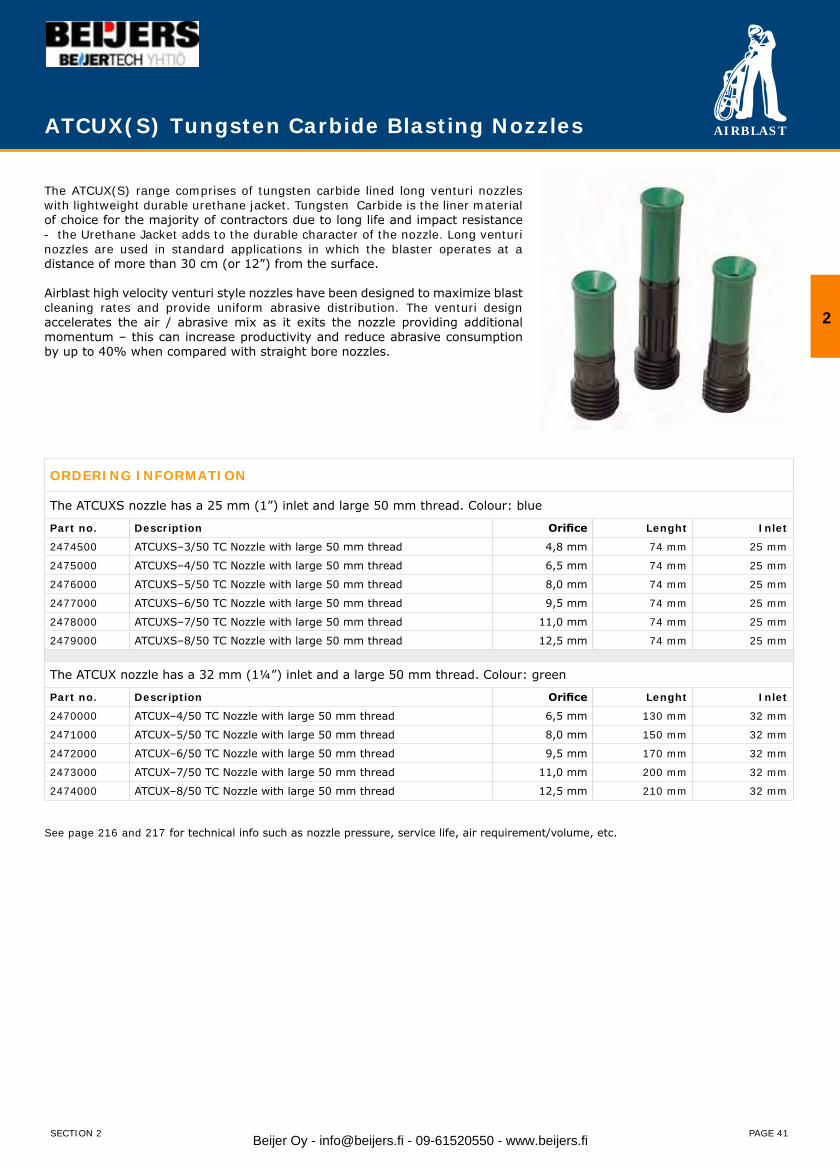
The ATCUX(S) range comprises of tungsten carbide lined long venturi nozzles with lightweight durable urethane jacket. Tungsten Carbide is the liner material of choice for the majority of contractors due to long life and impact resistance - the Urethane Jacket adds to the durable character of the nozzle. Long venturi nozzles are used in standard applications in which the blaster operates at a distance of more than 30 cm (or 12”) from the surface.
Airblast high velocity venturi style nozzles have been designed to maximize blast cleaning rates and provide uniform abrasive distribution. The venturi design accelerates the air / abrasive mix as it exits the nozzle providing additional momentum – this can increase productivity and reduce abrasive consumption by up to 40% when compared with straight bore nozzles.
2
SECTION 2 Beijer Oy - [email protected] - 09-61520550 - www.beijers.fi
AIRBLAST
PAGE 42
ADV Tungsten Carbide Double Venturi Nozzles
ORDERING INFORMATION
ADV - Double Venturi Nozzle. Aluminium Jacket/steel barrel/TC liner with fine thread (1.25” 11.5 TPI-NPSM)
Part no. Description Orifice (mm) Lenght (mm) Inlet (mm)
2440000 ADV-4 6,4 159 25
2441000 ADV-5 8,0 173 25
2442000 ADV-6 9,5 189 25
2443000 ADV-7 11,0 228 25
2444000 ADV-8 13.0 247 25
ADV - Double Venturi Nozzle. Aluminium Jacket/steel barrel/TC liner with large thread (2” 4.5 TPI UNC)
Part no. Description Orifice (mm) Lenght (mm) Inlet (mm)
2450000 ADV-4/50 6,4 159 25
2451000 ADV-5/50 8,0 173 25
2452000 ADV-6/50 9,5 189 25
2453000 ADV-7/50 11,0 228 25
2454000 ADV-8/50 13,0 247 25
See page 216 and 217 for technical info such as nozzle pressure, service life, air requirement/volume, etc.
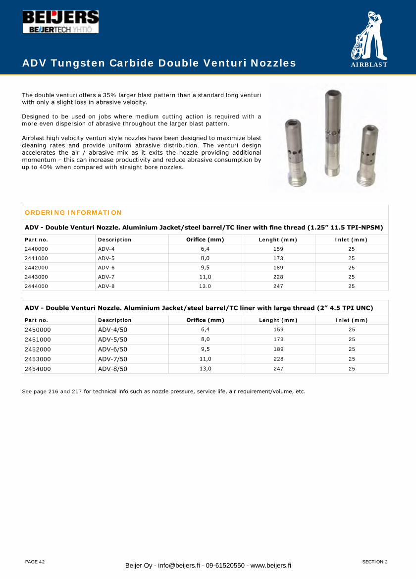
The double venturi offers a 35% larger blast pattern than a standard long venturi with only a slight loss in abrasive velocity.
Designed to be used on jobs where medium cutting action is required with a more even dispersion of abrasive throughout the larger blast pattern.
Airblast high velocity venturi style nozzles have been designed to maximize blast cleaning rates and provide uniform abrasive distribution. The venturi design accelerates the air / abrasive mix as it exits the nozzle providing additional momentum – this can increase productivity and reduce abrasive consumption by up to 40% when compared with straight bore nozzles.
SECTION 2Beijer Oy - [email protected] - 09-61520550 - www.beijers.fi
AIRBLAST
PAGE 43
ATST Tungsten Carbide Stick-up Blasting Nozzles
ORDERING INFORMATION
Part no. Description Orifice Lenght Inlet
2116000 ATST–5/25 TC Stick/up Nozzle 8.0 mm 115 mm 25 mm
2117000 ATST–6/25 TC Stick/up Nozzle 10,0 mm 115 mm 25 mm
2118000 ATST–5/32 TC Stick/up Nozzle 8.0 mm 115 mm 32 mm
2118100 ATST–6/32 TC Stick/up Nozzle 10,0 mm 115 mm 32 mm
2118200 ATST–8/32 TC Stick/up Nozzle 11.0 mm 115 mm 32 mm
See page 216 and 217 for technical info such as nozzle pressure, service life, air requirement/volume, etc.
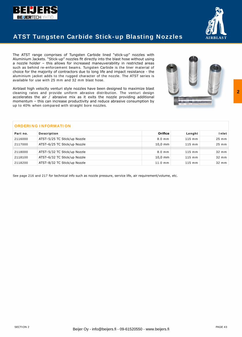
The ATST range comprises of Tungsten Carbide lined “stick-up” nozzles with Aluminium Jackets. “Stick-up” nozzles fit directly into the blast hose without using a nozzle holder – this allows for increased maneuverability in restricted areas such as behind re-enforcement beams. Tungsten Carbide is the liner material of choice for the majority of contractors due to long life and impact resistance - the aluminium jacket adds to the rugged character of the nozzle. The ATST series is available for use with 25 mm and 32 mm blast hose.
Airblast high velocity venturi style nozzles have been designed to maximize blast cleaning rates and provide uniform abrasive distribution. The venturi design accelerates the air / abrasive mix as it exits the nozzle providing additional momentum – this can increase productivity and reduce abrasive consumption by up to 40% when compared with straight bore nozzles.
2
SECTION 2 Beijer Oy - [email protected] - 09-61520550 - www.beijers.fi
AIRBLAST
PAGE 44
ABSN(X) Silicon Nitride Blasting Nozzles
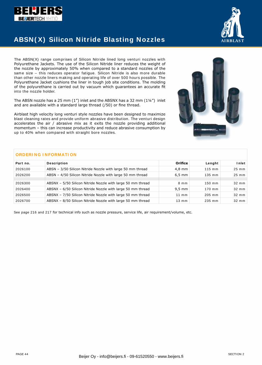
The ABSN(X) range comprises of Silicon Nitride lined long venturi nozzles with Polyurethane Jackets. The use of the Silicon Nitride liner reduces the weight of the nozzle by approximately 50% when compared to a standard nozzles of the same size – this reduces operator fatigue. Silicon Nitride is also more durable than other nozzle liners making and operating life of over 500 hours possible. The Polyurethane Jacket cushions the liner in tough job site conditions. The molding of the polyurethane is carried out by vacuum which guarantees an accurate fit into the nozzle holder.
The ABSN nozzle has a 25 mm (1”) inlet and the ABSNX has a 32 mm (1¼”) inlet and are available with a standard large thread (/50) or fine thread.
Airblast high velocity long venturi style nozzles have been designed to maximize blast cleaning rates and provide uniform abrasive distribution. The venturi design accelerates the air / abrasive mix as it exits the nozzle providing additional momentum – this can increase productivity and reduce abrasive consumption by up to 40% when compared with straight bore nozzles.
ORDERING INFORMATION
Part no. Description Orifice Lenght Inlet
2026100 ABSN – 3/50 Silicon Nitride Nozzle with large 50 mm thread 4,8 mm 115 mm 25 mm
2026200 ABSN – 4/50 Silicon Nitride Nozzle with large 50 mm thread 6,5 mm 135 mm 25 mm
2026300 ABSNX – 5/50 Silicon Nitride Nozzle with large 50 mm thread 8 mm 150 mm 32 mm
2026400 ABSNX – 6/50 Silicon Nitride Nozzle with large 50 mm thread 9,5 mm 170 mm 32 mm
2026500 ABSNX – 7/50 Silicon Nitride Nozzle with large 50 mm thread 11 mm 205 mm 32 mm
2026700 ABSNX – 8/50 Silicon Nitride Nozzle with large 50 mm thread 13 mm 235 mm 32 mm
See page 216 and 217 for technical info such as nozzle pressure, service life, air requirement/volume, etc.
SECTION 2Beijer Oy - [email protected] - 09-61520550 - www.beijers.fi
AIRBLAST
PAGE 45
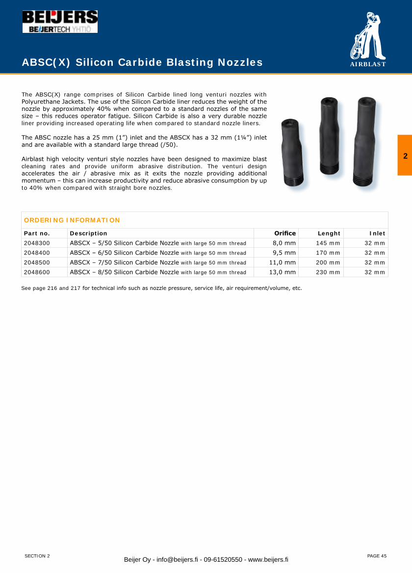
ABSC(X) Silicon Carbide Blasting Nozzles
The ABSC(X) range comprises of Silicon Carbide lined long venturi nozzles with Polyurethane Jackets. The use of the Silicon Carbide liner reduces the weight of the nozzle by approximately 40% when compared to a standard nozzles of the same size – this reduces operator fatigue. Silicon Carbide is also a very durable nozzle liner providing increased operating life when compared to standard nozzle liners.
The ABSC nozzle has a 25 mm (1”) inlet and the ABSCX has a 32 mm (1¼”) inlet and are available with a standard large thread (/50).
Airblast high velocity venturi style nozzles have been designed to maximize blast cleaning rates and provide uniform abrasive distribution. The venturi design accelerates the air / abrasive mix as it exits the nozzle providing additional momentum – this can increase productivity and reduce abrasive consumption by up to 40% when compared with straight bore nozzles.
ORDERING INFORMATION
Part no. Description Orifice Lenght Inlet2048300 ABSCX – 5/50 Silicon Carbide Nozzle with large 50 mm thread 8,0 mm 145 mm 32 mm2048400 ABSCX – 6/50 Silicon Carbide Nozzle with large 50 mm thread 9,5 mm 170 mm 32 mm2048500 ABSCX – 7/50 Silicon Carbide Nozzle with large 50 mm thread 11,0 mm 200 mm 32 mm2048600 ABSCX – 8/50 Silicon Carbide Nozzle with large 50 mm thread 13,0 mm 230 mm 32 mm
See page 216 and 217 for technical info such as nozzle pressure, service life, air requirement/volume, etc.
2
SECTION 2 Beijer Oy - [email protected] - 09-61520550 - www.beijers.fi
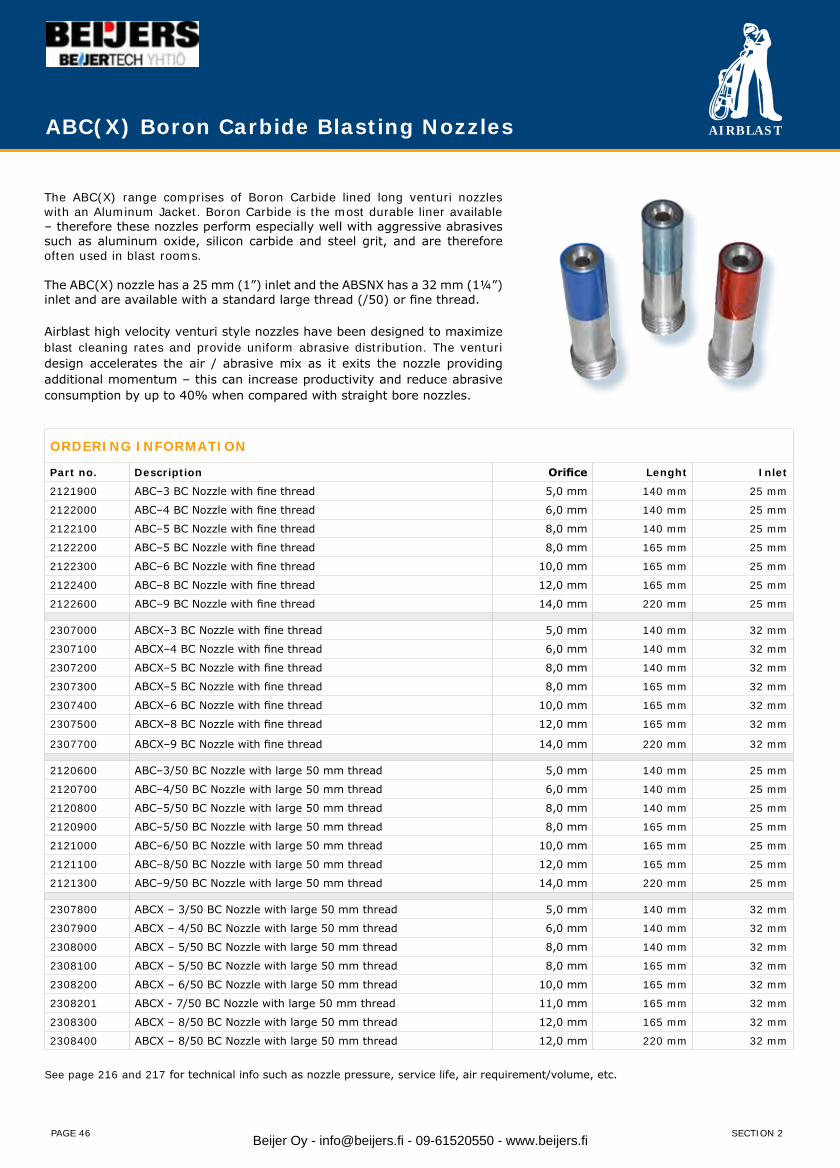
AIRBLAST
PAGE 46
ABC(X) Boron Carbide Blasting Nozzles
ORDERING INFORMATION
Part no. Description Orifice Lenght Inlet
2121900 ABC–3 BC Nozzle with fine thread 5,0 mm 140 mm 25 mm
2122000 ABC–4 BC Nozzle with fine thread 6,0 mm 140 mm 25 mm
2122100 ABC–5 BC Nozzle with fine thread 8,0 mm 140 mm 25 mm
2122200 ABC–5 BC Nozzle with fine thread 8,0 mm 165 mm 25 mm
2122300 ABC–6 BC Nozzle with fine thread 10,0 mm 165 mm 25 mm
2122400 ABC–8 BC Nozzle with fine thread 12,0 mm 165 mm 25 mm
2122600 ABC–9 BC Nozzle with fine thread 14,0 mm 220 mm 25 mm
2307000 ABCX–3 BC Nozzle with fine thread 5,0 mm 140 mm 32 mm
2307100 ABCX–4 BC Nozzle with fine thread 6,0 mm 140 mm 32 mm
2307200 ABCX–5 BC Nozzle with fine thread 8,0 mm 140 mm 32 mm
2307300 ABCX–5 BC Nozzle with fine thread 8,0 mm 165 mm 32 mm
2307400 ABCX–6 BC Nozzle with fine thread 10,0 mm 165 mm 32 mm
2307500 ABCX–8 BC Nozzle with fine thread 12,0 mm 165 mm 32 mm
2307700 ABCX–9 BC Nozzle with fine thread 14,0 mm 220 mm 32 mm
2120600 ABC–3/50 BC Nozzle with large 50 mm thread 5,0 mm 140 mm 25 mm
2120700 ABC–4/50 BC Nozzle with large 50 mm thread 6,0 mm 140 mm 25 mm
2120800 ABC–5/50 BC Nozzle with large 50 mm thread 8,0 mm 140 mm 25 mm
2120900 ABC–5/50 BC Nozzle with large 50 mm thread 8,0 mm 165 mm 25 mm
2121000 ABC–6/50 BC Nozzle with large 50 mm thread 10,0 mm 165 mm 25 mm
2121100 ABC–8/50 BC Nozzle with large 50 mm thread 12,0 mm 165 mm 25 mm
2121300 ABC–9/50 BC Nozzle with large 50 mm thread 14,0 mm 220 mm 25 mm
2307800 ABCX – 3/50 BC Nozzle with large 50 mm thread 5,0 mm 140 mm 32 mm
2307900 ABCX – 4/50 BC Nozzle with large 50 mm thread 6,0 mm 140 mm 32 mm
2308000 ABCX – 5/50 BC Nozzle with large 50 mm thread 8,0 mm 140 mm 32 mm
2308100 ABCX – 5/50 BC Nozzle with large 50 mm thread 8,0 mm 165 mm 32 mm
2308200 ABCX – 6/50 BC Nozzle with large 50 mm thread 10,0 mm 165 mm 32 mm
2308201 ABCX - 7/50 BC Nozzle with large 50 mm thread 11,0 mm 165 mm 32 mm
2308300 ABCX – 8/50 BC Nozzle with large 50 mm thread 12,0 mm 165 mm 32 mm
2308400 ABCX – 8/50 BC Nozzle with large 50 mm thread 12,0 mm 220 mm 32 mm
See page 216 and 217 for technical info such as nozzle pressure, service life, air requirement/volume, etc.
The ABC(X) range comprises of Boron Carbide lined long venturi nozzles with an Aluminum Jacket. Boron Carbide is the most durable liner available – therefore these nozzles perform especially well with aggressive abrasives such as aluminum oxide, silicon carbide and steel grit, and are therefore often used in blast rooms.
The ABC(X) nozzle has a 25 mm (1”) inlet and the ABSNX has a 32 mm (1¼”) inlet and are available with a standard large thread (/50) or fine thread.
Airblast high velocity venturi style nozzles have been designed to maximize blast cleaning rates and provide uniform abrasive distribution. The venturi design accelerates the air / abrasive mix as it exits the nozzle providing additional momentum – this can increase productivity and reduce abrasive consumption by up to 40% when compared with straight bore nozzles.
SECTION 2Beijer Oy - [email protected] - 09-61520550 - www.beijers.fi
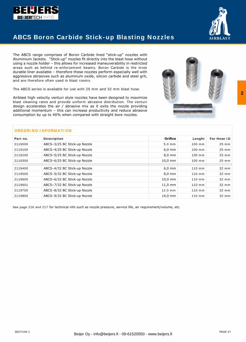
AIRBLAST
PAGE 47
ABCS Boron Carbide Stick-up Blasting Nozzles
The ABCS range comprises of Boron Carbide lined “stick-up” nozzles with Aluminium Jackets. “Stick-up” nozzles fit directly into the blast hose without using a nozzle holder – this allows for increased maneuverability in restricted areas such as behind re-enforcement beams. Boron Carbide is the most durable liner available – therefore these nozzles perform especially well with aggressive abrasives such as aluminum oxide, silicon carbide and steel grit, and are therefore often used in blast rooms.
The ABCS series is available for use with 25 mm and 32 mm blast hose.
Airblast high velocity venturi style nozzles have been designed to maximize blast cleaning rates and provide uniform abrasive distribution. The venturi design accelerates the air / abrasive mix as it exits the nozzle providing additional momentum – this can increase productivity and reduce abrasive consumption by up to 40% when compared with straight bore nozzles.
ORDERING INFORMATION
Part no. Description Orifice Lenght For Hose ID
2119000 ABCS–3/25 BC Stick-up Nozzle 5.0 mm 100 mm 25 mm
2119100 ABCS–4/25 BC Stick-up Nozzle 6,0 mm 100 mm 25 mm
2119200 ABCS–5/25 BC Stick-up Nozzle 8,0 mm 100 mm 25 mm
2119300 ABCS–6/25 BC Stick-up Nozzle 10,0 mm 100 mm 25 mm
2119400 ABCS–4/32 BC Stick-up Nozzle 6,0 mm 110 mm 32 mm
2119500 ABCS–5/32 BC Stick-up Nozzle 8,0 mm 110 mm 32 mm
2119600 ABCS–6/32 BC Stick-up Nozzle 10,0 mm 110 mm 32 mm
2119601 ABCS–7/32 BC Stick-up Nozzle 11,0 mm 110 mm 32 mm
2119700 ABCS–8/32 BC Stick-up Nozzle 12.0 mm 110 mm 32 mm
2119800 ABCS–9/32 BC Stick-up Nozzle 14,0 mm 110 mm 32 mm
See page 216 and 217 for technical info such as nozzle pressure, service life, air requirement/volume, etc.
2
SECTION 2 Beijer Oy - [email protected] - 09-61520550 - www.beijers.fi
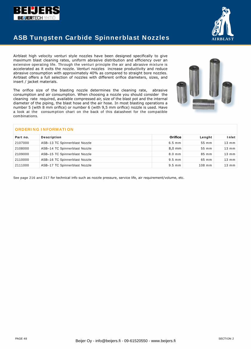
AIRBLAST
PAGE 48
ASB Tungsten Carbide Spinnerblast Nozzles
ORDERING INFORMATION
Part no. Description Orifice Lenght Inlet
2107000 ASB–13 TC Spinnerblast Nozzle 6.5 mm 55 mm 13 mm
2108000 ASB–14 TC Spinnerblast Nozzle 8,0 mm 55 mm 13 mm
2109000 ASB–15 TC Spinnerblast Nozzle 8.0 mm 85 mm 13 mm
2110000 ASB–16 TC Spinnerblast Nozzle 9.5 mm 65 mm 13 mm
2111000 ASB–17 TC Spinnerblast Nozzle 9.5 mm 108 mm 13 mm
See page 216 and 217 for technical info such as nozzle pressure, service life, air requirement/volume, etc.
Airblast high velocity venturi style nozzles have been designed specifically to give maximum blast cleaning rates, uniform abrasive distribution and efficiency over an extensive operating life. Through the venturi principle the air and abrasive mixture is accelerated as it exits the nozzle. Venturi nozzles increase productivity and reduce abrasive consumption with approximately 40% as compared to straight bore nozzles. Airblast offers a full selection of nozzles with different orifice diameters, sizes, and insert / jacket materials.
The orifice size of the blasting nozzle determines the cleaning rate, abrasive consumption and air consumption. When choosing a nozzle you should consider the cleaning rate required, available compressed air, size of the blast pot and the internal diameter of the piping, the blast hose and the air hose. In most blasting operations a number 5 (with 8 mm orifice) or number 6 (with 9,5 mm orifice) nozzle is used. Have a look at the consumption chart on the back of this datasheet for the compatible combinations.
SECTION 2Beijer Oy - [email protected] - 09-61520550 - www.beijers.fi

AIRBLAST
PAGE 49
WIN Water Injection Blasting Nozzles
Airblast high velocity venturi style nozzles have been designed specifically to give maximum blast cleaning rates, uniform abrasive distribution and efficiency over an extensive operating life. Through the venturi principle the air and abrasive mixture is accelerated as it exits the nozzle. Venturi nozzles increase productivity and reduce abrasive consumption with approximately 40% as compared to straight bore nozzles. Airblast offers a full selection of nozzles with different orifice diameters, sizes, and insert / jacket materials.
WIN NozzleThe WIN (Water Injection Nozzle) system is a simple, cost effective solution for high production, wet abrasive blasting that can be used with your existing pressure blast equipment. The system can be used with water from a tap or with rust inhibitors supplied through any simple pump. No special equipment is required. The WIN system offers the highest performance possible in wet abrasive blasting technology.
ORDERING INFORMATION
Part no. Description Orifice Lenght Inlet
2460000 WIN-4/50 Water Injection Nozzle with large 50 mm thread 6,4 mm 149 mm 25 mm
2461000 WIN-5/50 Water Injection Nozzle with large 50 mm thread 7,9 mm 158 mm 25 mm
2462000 WIN-6/50 Water Injection Nozzle with large 50 mm thread 9,5 mm 171 mm 25 mm
2463000 WIN-8/50 Water Injection Nozzle with large 50 mm thread 12 mm 227 mm 25 mm
See page 216 and 217 for technical info such as nozzle pressure, service life, air requirement/volume, etc.
2
SECTION 2 Beijer Oy - [email protected] - 09-61520550 - www.beijers.fi
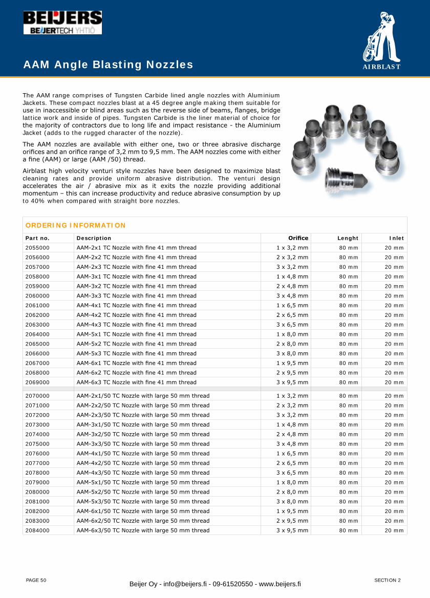
AIRBLAST
PAGE 50
AAM Angle Blasting Nozzles
The AAM range comprises of Tungsten Carbide lined angle nozzles with Aluminium Jackets. These compact nozzles blast at a 45 degree angle making them suitable for use in inaccessible or blind areas such as the reverse side of beams, flanges, bridge lattice work and inside of pipes. Tungsten Carbide is the liner material of choice for the majority of contractors due to long life and impact resistance - the Aluminium Jacket (adds to the rugged character of the nozzle).
The AAM nozzles are available with either one, two or three abrasive discharge orifices and an orifice range of 3,2 mm to 9,5 mm. The AAM nozzles come with either a fine (AAM) or large (AAM /50) thread.
Airblast high velocity venturi style nozzles have been designed to maximize blast cleaning rates and provide uniform abrasive distribution. The venturi design accelerates the air / abrasive mix as it exits the nozzle providing additional momentum – this can increase productivity and reduce abrasive consumption by up to 40% when compared with straight bore nozzles.
ORDERING INFORMATION
Part no. Description Orifice Lenght Inlet
2055000 AAM-2x1 TC Nozzle with fine 41 mm thread 1 x 3,2 mm 80 mm 20 mm
2056000 AAM-2x2 TC Nozzle with fine 41 mm thread 2 x 3,2 mm 80 mm 20 mm
2057000 AAM-2x3 TC Nozzle with fine 41 mm thread 3 x 3,2 mm 80 mm 20 mm
2058000 AAM-3x1 TC Nozzle with fine 41 mm thread 1 x 4,8 mm 80 mm 20 mm
2059000 AAM-3x2 TC Nozzle with fine 41 mm thread 2 x 4,8 mm 80 mm 20 mm
2060000 AAM-3x3 TC Nozzle with fine 41 mm thread 3 x 4,8 mm 80 mm 20 mm
2061000 AAM-4x1 TC Nozzle with fine 41 mm thread 1 x 6,5 mm 80 mm 20 mm
2062000 AAM-4x2 TC Nozzle with fine 41 mm thread 2 x 6,5 mm 80 mm 20 mm
2063000 AAM-4x3 TC Nozzle with fine 41 mm thread 3 x 6,5 mm 80 mm 20 mm
2064000 AAM-5x1 TC Nozzle with fine 41 mm thread 1 x 8,0 mm 80 mm 20 mm
2065000 AAM-5x2 TC Nozzle with fine 41 mm thread 2 x 8,0 mm 80 mm 20 mm
2066000 AAM-5x3 TC Nozzle with fine 41 mm thread 3 x 8,0 mm 80 mm 20 mm
2067000 AAM-6x1 TC Nozzle with fine 41 mm thread 1 x 9,5 mm 80 mm 20 mm
2068000 AAM-6x2 TC Nozzle with fine 41 mm thread 2 x 9,5 mm 80 mm 20 mm
2069000 AAM-6x3 TC Nozzle with fine 41 mm thread 3 x 9,5 mm 80 mm 20 mm
2070000 AAM-2x1/50 TC Nozzle with large 50 mm thread 1 x 3,2 mm 80 mm 20 mm
2071000 AAM-2x2/50 TC Nozzle with large 50 mm thread 2 x 3,2 mm 80 mm 20 mm
2072000 AAM-2x3/50 TC Nozzle with large 50 mm thread 3 x 3,2 mm 80 mm 20 mm
2073000 AAM-3x1/50 TC Nozzle with large 50 mm thread 1 x 4,8 mm 80 mm 20 mm
2074000 AAM-3x2/50 TC Nozzle with large 50 mm thread 2 x 4,8 mm 80 mm 20 mm
2075000 AAM-3x3/50 TC Nozzle with large 50 mm thread 3 x 4,8 mm 80 mm 20 mm
2076000 AAM-4x1/50 TC Nozzle with large 50 mm thread 1 x 6,5 mm 80 mm 20 mm
2077000 AAM-4x2/50 TC Nozzle with large 50 mm thread 2 x 6,5 mm 80 mm 20 mm
2078000 AAM-4x3/50 TC Nozzle with large 50 mm thread 3 x 6,5 mm 80 mm 20 mm
2079000 AAM-5x1/50 TC Nozzle with large 50 mm thread 1 x 8,0 mm 80 mm 20 mm
2080000 AAM-5x2/50 TC Nozzle with large 50 mm thread 2 x 8,0 mm 80 mm 20 mm
2081000 AAM-5x3/50 TC Nozzle with large 50 mm thread 3 x 8,0 mm 80 mm 20 mm
2082000 AAM-6x1/50 TC Nozzle with large 50 mm thread 1 x 9,5 mm 80 mm 20 mm
2083000 AAM-6x2/50 TC Nozzle with large 50 mm thread 2 x 9,5 mm 80 mm 20 mm
2084000 AAM-6x3/50 TC Nozzle with large 50 mm thread 3 x 9,5 mm 80 mm 20 mm
SECTION 2Beijer Oy - [email protected] - 09-61520550 - www.beijers.fi
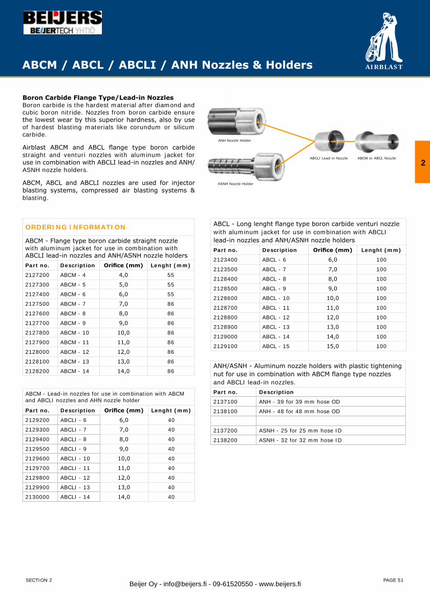
AIRBLAST
PAGE 51
ABCM / ABCL / ABCLI / ANH Nozzles & Holders
ORDERING INFORMATION
ABCM - Flange type boron carbide straight nozzle with aluminum jacket for use in combination with ABCLI lead-in nozzles and ANH/ASNH nozzle holdersPart no. Description Orifice (mm) Lenght (mm)
2127200 ABCM - 4 4,0 55
2127300 ABCM - 5 5,0 55
2127400 ABCM - 6 6,0 55
2127500 ABCM - 7 7,0 86
2127600 ABCM - 8 8,0 86
2127700 ABCM - 9 9,0 86
2127800 ABCM - 10 10,0 86
2127900 ABCM - 11 11,0 86
2128000 ABCM - 12 12,0 86
2128100 ABCM - 13 13,0 86
2128200 ABCM - 14 14,0 86
ABCM - Lead-in nozzles for use in combination with ABCM and ABCLI nozzles and AHN nozzle holder
Part no. Description Orifice (mm) Lenght (mm)
2129200 ABCLI - 6 6,0 40
2129300 ABCLI - 7 7,0 40
2129400 ABCLI - 8 8,0 40
2129500 ABCLI - 9 9,0 40
2129600 ABCLI - 10 10,0 40
2129700 ABCLI - 11 11,0 40
2129800 ABCLI - 12 12,0 40
2129900 ABCLI - 13 13,0 40
2130000 ABCLI - 14 14,0 40
Boron Carbide Flange Type/Lead-in Nozzles Boron carbide is the hardest material after diamond and cubic boron nitride. Nozzles from boron carbide ensure the lowest wear by this superior hardness, also by use of hardest blasting materials like corundum or silicum carbide.
Airblast ABCM and ABCL flange type boron carbide straight and venturi nozzles with aluminum jacket for use in combination with ABCLI lead-in nozzles and ANH/ASNH nozzle holders.
ABCM, ABCL and ABCLI nozzles are used for injector blasting systems, compressed air blasting systems & blasting.ystems
ASNH Nozzle Holder
ABCLI Lead-in Nozzle ABCM or ABCL Nozzle
ANH Nozzle Holder
ABCL - Long lenght flange type boron carbide venturi nozzle with aluminum jacket for use in combination with ABCLI lead-in nozzles and ANH/ASNH nozzle holdersPart no. Description Orifice (mm) Lenght (mm)
2123400 ABCL - 6 6,0 100
2123500 ABCL - 7 7,0 100
2128400 ABCL - 8 8,0 100
2128500 ABCL - 9 9,0 100
2128600 ABCL - 10 10,0 100
2128700 ABCL - 11 11,0 100
2128800 ABCL - 12 12,0 100
2128900 ABCL - 13 13,0 100
2129000 ABCL - 14 14,0 100
2129100 ABCL - 15 15,0 100
ANH/ASNH - Aluminum nozzle holders with plastic tightening nut for use in combination with ABCM flange type nozzles and ABCLI lead-in nozzles.Part no. Description
2137100 ANH - 39 for 39 mm hose OD
2138100 ANH - 48 for 48 mm hose OD
2137200 ASNH - 25 for 25 mm hose ID
2138200 ASNH - 32 for 32 mm hose ID
2
SECTION 2 Beijer Oy - [email protected] - 09-61520550 - www.beijers.fi

AIRBLAST
PAGE 52
ABCFT/ABCA/ABCC/ABCR Nozzles
ORDERING INFORMATION
ABCFT - Flange type boron carbide fishtail nozzle for use in combination with ABCLI lead-in nozzles and ANH/ASNH nozzle holdersPart no. Description Orifice
(mm)Lenght (mm)
2130200 ABCFT - 10/4 10 x 4 72
2130300 ABCFT - 15/5 15 x 5 72
2130400 ABCFT - 16/8 16 x 8 82
ABCA - Flange type boron carbide angle nozzle for use in combination with ABCLI lead-in nozzles and ANH/ASNH nozzle holdersPart no. Description Orifice
(mm)Lenght (mm)
Angle (°)
2130700 ABCA - 20/8 8 100 20
2130800 ABCA - 20/10 10 100 20
2130900 ABCA - 20/12 12 100 20
2131000 ABCA - 25/8 8 100 25
2131100 ABCA - 25/10 10 100 25
2131200 ABCA - 25/12 12 100 25
2131300 ABCA - 30/8 8 105 30
2131400 ABCA - 30/10 10 105 30
2131500 ABCA - 30/12 12 105 30
2131600 ABCA - 40/8 8 115 40
2131700 ABCA - 40/10 10 115 40
2131800 ABCA - 40/12 12 115 40
ABCC - Curved nozzle with fine 26 mm thread (¾”)
Part no. Description Orifice (mm)
Lenght (mm)
Angle (°)
2131900 ABCC - 40/6 6,0 125 40
2132100 ABCC - 40/8 8,0 125 40
2132200 ABCC - 40/10 10,0 125 40
ABCR - Boron carbide blast head 360° with metal jacket and replaceable deflection piecePart no. Descrip-
tionThread
(T”)Diameter
(mm)Lenght (mm)
2309000 ABCR - 38 3/8 22 61
2309100 ABCR - 24 1/2 23 61
2309200 ABCR - 34 3/4 30 73
2309300 ABCR - 44 1 1/4 38 73
2309400 ABCR - 54 1 1/4 47 78
2309500 ABCA - 64 1 1/2 53 78
2309600 Deflection piece for ABCR-38
2309700 Deflection piece for ABCR-24
2309800 Deflection piece for ABCR-34
2309900 Deflection piece for ABCR-44
2310000 Deflection piece for ABCR-54
SECTION 2Beijer Oy - [email protected] - 09-61520550 - www.beijers.fi
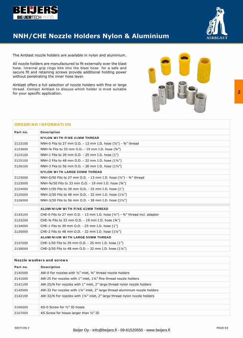
AIRBLAST
PAGE 53
The Airblast nozzle holders are available in nylon and aluminium.
All nozzle holders are manufactured to fit externally over the blast hose. Internal grip rings bite into the blast hose for a safe and secure fit and retaining screws provide additional holding power without penetrating the inner hose layer.
Airblast offers a full selection of nozzle holders with fine or large thread. Contact Airblast to discuss which holder is most suitable for your specific application.
ORDERING INFORMATION
Part no. Description
NYLON WITH FINE 41MM THREAD
2123100 NNH-0 Fits to 27 mm O.D. - 13 mm I.D. hose (½”) - ¾” thread
2123600 NNH-¾ Fits to 33 mm O.D. - 19 mm I.D. hose (¾”)
2124100 NNH-1 Fits to 39 mm O.D. - 25 mm I.D. hose (1”)
2125100 NNH-2 Fits to 48 mm O.D. - 32 mm I.D. hose (1¼”)
2126100 NNH-3 Fits to 56 mm O.D. - 38 mm I.D. hose (1½”)
NYLON WITH LARGE 50MM THREAD
2123000 NNH-0/50 Fits to 27 mm O.D. - 13 mm I.D. hose (½”) - ¾” thread
2123500 NNH-¾/50 Fits to 33 mm O.D. - 19 mm I.D. hose (¾”)
2124000 NNH-1/50 Fits to 39 mm O.D. - 25 mm I.D. hose (1”)
2125000 NNH-2/50 Fits to 48 mm O.D. - 32 mm I.D. hose (1¼”)
2126000 NNH-3/50 Fits to 56 mm O.D. - 38 mm I.D. hose (1½”)
ALUMINIUM WITH FINE 41MM THREAD
2133100 CHE-0 Fits to 27 mm O.D. - 13 mm I.D. hose (½”) - ¾” thread incl. adaptor
2133200 CHE-¾ Fits to 33 mm O.D. - 19 mm I.D. hose (¾”)
2134000 CHE-1 Fits to 39 mm O.D. - 25 mm I.D. hose (1”)
2135000 CHE-2 Fits to 48 mm O.D. - 32 mm I.D. hose (1¼”)
ALUMINIUM WITH LARGE 50MM THREAD
2137000 CHE-1/50 Fits to 39 mm O.D. - 25 mm I.D. hose (1”)
2138000 CHE-2/50 Fits to 48 mm O.D. - 32 mm I.D. hose (1¼”)
Nozzle washers and screws
Part no. Description
2140000 AW-0 For nozzles with ½” inlet, ¾” thread nozzle holders
2141000 AW-25 For nozzles with 1” inlet, 1¼” fine thread nozzle holders
2141100 AW-25/N For nozzles with 1” inlet, 2” large thread nylon nozzle holders
2142000 AW-32 For nozzles with 1¼” inlet, 2” large thread aluminium nozzle holders
2142100 AW-32/N For nozzles with 1¼” inlet, 2” large thread nylon nozzle holders
2166000 KS-0 Screw for ½” ID hoses
2167000 KS Screw for hoses larger than ½” ID
NNH/CHE Nozzle Holders Nylon & Aluminium
2
SECTION 2 Beijer Oy - [email protected] - 09-61520550 - www.beijers.fi
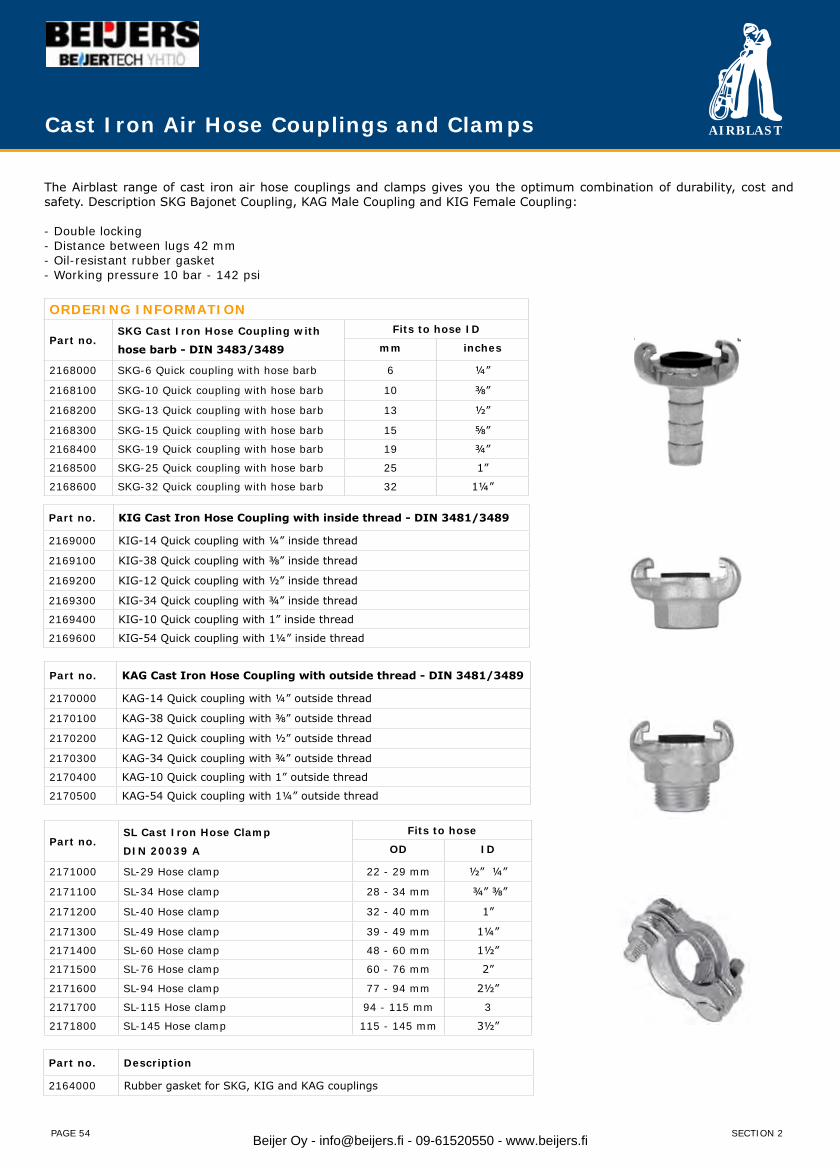
AIRBLAST
PAGE 54
The Airblast range of cast iron air hose couplings and clamps gives you the optimum combination of durability, cost and safety. Description SKG Bajonet Coupling, KAG Male Coupling and KIG Female Coupling:
- Double locking- Distance between lugs 42 mm- Oil-resistant rubber gasket- Working pressure 10 bar - 142 psi
ORDERING INFORMATION
Part no.SKG Cast Iron Hose Coupling with
hose barb - DIN 3483/3489
Fits to hose ID
mm inches
2168000 SKG-6 Quick coupling with hose barb 6 ¼”
2168100 SKG-10 Quick coupling with hose barb 10 ⅜”
2168200 SKG-13 Quick coupling with hose barb 13 ½”
2168300 SKG-15 Quick coupling with hose barb 15 ⅝”
2168400 SKG-19 Quick coupling with hose barb 19 ¾”
2168500 SKG-25 Quick coupling with hose barb 25 1”
2168600 SKG-32 Quick coupling with hose barb 32 1¼”
Part no. KIG Cast Iron Hose Coupling with inside thread - DIN 3481/3489
2169000 KIG-14 Quick coupling with ¼” inside thread
2169100 KIG-38 Quick coupling with ⅜” inside thread
2169200 KIG-12 Quick coupling with ½” inside thread
2169300 KIG-34 Quick coupling with ¾” inside thread
2169400 KIG-10 Quick coupling with 1” inside thread
2169600 KIG-54 Quick coupling with 1¼” inside thread
Part no. KAG Cast Iron Hose Coupling with outside thread - DIN 3481/3489
2170000 KAG-14 Quick coupling with ¼” outside thread
2170100 KAG-38 Quick coupling with ⅜” outside thread
2170200 KAG-12 Quick coupling with ½” outside thread
2170300 KAG-34 Quick coupling with ¾” outside thread
2170400 KAG-10 Quick coupling with 1” outside thread
2170500 KAG-54 Quick coupling with 1¼” outside thread
Part no. Description
2164000 Rubber gasket for SKG, KIG and KAG couplings
Part no.SL Cast Iron Hose Clamp
DIN 20039 A
Fits to hose
OD ID
2171000 SL-29 Hose clamp 22 - 29 mm ½” ¼”
2171100 SL-34 Hose clamp 28 - 34 mm ¾” ⅜”
2171200 SL-40 Hose clamp 32 - 40 mm 1”
2171300 SL-49 Hose clamp 39 - 49 mm 1¼”
2171400 SL-60 Hose clamp 48 - 60 mm 1½”
2171500 SL-76 Hose clamp 60 - 76 mm 2”
2171600 SL-94 Hose clamp 77 - 94 mm 2½”
2171700 SL-115 Hose clamp 94 - 115 mm 3
2171800 SL-145 Hose clamp 115 - 145 mm 3½”
Cast Iron Air Hose Couplings and Clamps
SECTION 2Beijer Oy - [email protected] - 09-61520550 - www.beijers.fi

AIRBLAST
PAGE 55
Quick Couplings
Nylon and Cast Iron Couplings for blast hose and machinesThe Airblast range of cast iron and nylon blast hose and machine couplings gives you the optimum combination of durability, cost and safety.
Description Cast Iron Hose and Machine Couplings:- Zinc-plated, modular- Graphit cast iron- Gasket in Perbunan
Description Nylon Hose and Machine Couplings:The lightweight super-strong Airblast Nylon Hose and Machine Couplings are made out of the finest quality of nylon material which allows it in strength, durability and weight an advantage over brass. The universal quarter turn design makes it possible to couple different size hoses and couplings made of different material. Airblast Nylon Hose and Machine Couplings are manufactured within the narrowest of tolerances assuring a perfect match all the time.
ORDERING INFORMATION
Cast Hose / Machine Couplings
Part no. Description
Fits to hose
ODmm
ID
mm inches
2147000 CQT-1 Cast iron hose coupling 39 25 1”
2148000 CQT-2 Cast iron hose coupling 48 32 1¼”
2149000 CQT-3 Cast iron hose coupling 56 38 1½”
2150000 CQT-4 Cast iron hose coupling 60 42 1¾”
2163000 CFT Cast Iron machine coupling with 1¼” female thread
Nylon Hose / Machine Couplings
Part no. Description
Fits to hose
ODmm
ID
mm inches
2150900 CQN-¾ Nylon hose coupling 33 19 ¾”
2151000 CQN-1 Nylon hose coupling 39 25 1”
2152000 CQN-2 Nylon hose coupling 48 32 1¼”
2153000 CQN-3 Nylon hose coupling 56 38 1½”
2154000 CQN-4 Nylon hose coupling 60 42 1¾”
2163100 CFN Nylon machine coupling with 1¼” female thread
2154100 Safety spring for CQN couplings
Gaskets
Part no. Description
2165000 CQG Gasket for CQT and CFT couplings
2165100 CQG-1 Gasket for CQN-¾ and 1
2165200 CQG-2 Gasket for CQN-2, -3, -4 and CFN coupling
ScrewsPart no. Description
2166000 KS-0 Screw for ½” ID hoses
2167000 KS Screw for hoses larger than ½” ID
2
SECTION 2 Beijer Oy - [email protected] - 09-61520550 - www.beijers.fi

AIRBLAST
PAGE 56
Brass - MS 58 DN 7,2 for airThe Airblast range of brass quick connect couplings gives you the optimum combination of durability, cost and safety.
Description Hose Coupling, Female Coupling, Male coupling:- Single shut-off- Euro standard- Working pressure 35 bar - 500 psi
Description Plug Nipples with Female Thread, Plug Nipples with Male Thread and Plug Nipples with Hose Stem for air- Euro standard- Working pressure 35 bar - 500 psi
Airblast offers a full selection of air couplings as well as other couplings used in blast cleaning and paint spraying operation – contact Airblast to discuss which coupling is most suitable for your specific application.
Quick Connect Couplings (brass)
ORDERING INFORMATIONQuick Connect Coupling with outside thread - brassPart no. Description
2174100 CCC-14/O Quick coupling with ¼” outside thread
2174200 CCC-38/O Quick coupling with ⅜” outside thread
2174300 CCC-12/O Quick coupling with ½” outside thread
Quick Connect Coupling with inside thread - brass
Part no. Description
2175100 CCC-14/I Quick coupling with ¼” inside thread
2175200 CCC-38/I Quick coupling with ⅜” inside thread
2175300 CCC-12/I Quick coupling with ½” inside thread
Quick Connect Coupling with hose barb - brass
Part no. Description
2176000 CCC-14/F Quick coupling with hose barb (6 mm)
2176100 CCC-38/F Quick coupling with hose barb (9 mm)
2176200 CCC-12/F Quick coupling with hose barb (13 mm)
Manifolds with Quick Connect Coupling - brass
Part no. Description
2180000 M-2 Manifold for 2 users (⅜” with inside thread)
2180100 M-3 Manifold for 3 users (⅜” with inside thread)
Quick Connect Plug with outside thread - brass
Part no. Description
2177000 OF-18 Quick connect plug with ⅛” outside thread
2177100 OF-14 Quick connect plug with ¼” outside thread
2177200 OF-38 Quick connect plug with ⅜” outside thread
2177300 OF-12 Quick connect plug with ½” outside thread
Quick Connect Plug with inside thread - brass
Part no. Description
2178000 IF-18 Quick connect plug with ⅛” inside thread
2178100 IF-14 Quick connect plug with ¼” inside thread
2178200 IF-38 Quick connect plug with ⅜” inside thread
2178300 IF-12 Quick connect plug with ½” inside thread
Quick Connect Plug hose barb - brass
Part no. Description
2179000 F-14 Quick connect plug with hose barb (6 mm)
2179100 F-38 Quick connect plug with hose barb (9 mm)
2179200 F-12 Quick connect plug with hose barb (13 mm)
SECTION 2Beijer Oy - [email protected] - 09-61520550 - www.beijers.fi
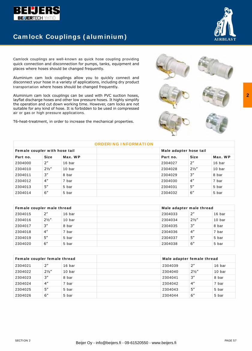
AIRBLAST
PAGE 57
Camlock Couplings (aluminium)
Camlock couplings are well-known as quick hose coupling providing quick connection and disconnection for pumps, tanks, equipment and places where hoses should be changed frequently.
Aluminium cam lock couplings allow you to quickly connect and disconnect your hose in a variety of applications, including dry product transportation where hoses should be changed frequently.
Aluminium cam lock couplings can be used with PVC suction hoses, layflat discharge hoses and other low pressure hoses. It highly simplify the operation and cut down working time. However, cam locks are not suitable for any kind of hose. It is forbidden to be used in compressed air or gas or high pressure applications.
T6-heat-treatment, in order to increase the mechanical properties.
ORDERING INFORMATIONFemale coupler with hose tail Male adapter hose tail
Part no. Size Max. WP Part no. Size Max. WP2304000 2” 16 bar 2304027 2” 16 bar2304010 2½” 10 bar 2304028 2½” 10 bar2304011 3” 8 bar 2304029 3” 8 bar2304012 4” 7 bar 2304030 4” 7 bar2304013 5” 5 bar 2304031 5” 5 bar2304014 6” 5 bar 2304032 6” 5 bar
Female coupler male thread Male adapter male thread2304015 2” 16 bar 2304033 2” 16 bar2304016 2½” 10 bar 2304034 2½” 10 bar2304017 3” 8 bar 2304035 3” 8 bar2304018 4” 7 bar 2304036 4” 7 bar2304019 5” 5 bar 2304037 5” 5 bar2304020 6” 5 bar 2304038 6” 5 bar
Female coupler female thread Male adapter female thread
2304021 2” 16 bar 2304039 2” 16 bar2304022 2½” 10 bar 2304040 2½” 10 bar2304023 3” 8 bar 2304041 3” 8 bar2304024 4” 7 bar 2304042 4” 7 bar2304025 5” 5 bar 2304043 5” 5 bar2304026 6” 5 bar 2304044 6” 5 bar
2
SECTION 2 Beijer Oy - [email protected] - 09-61520550 - www.beijers.fi
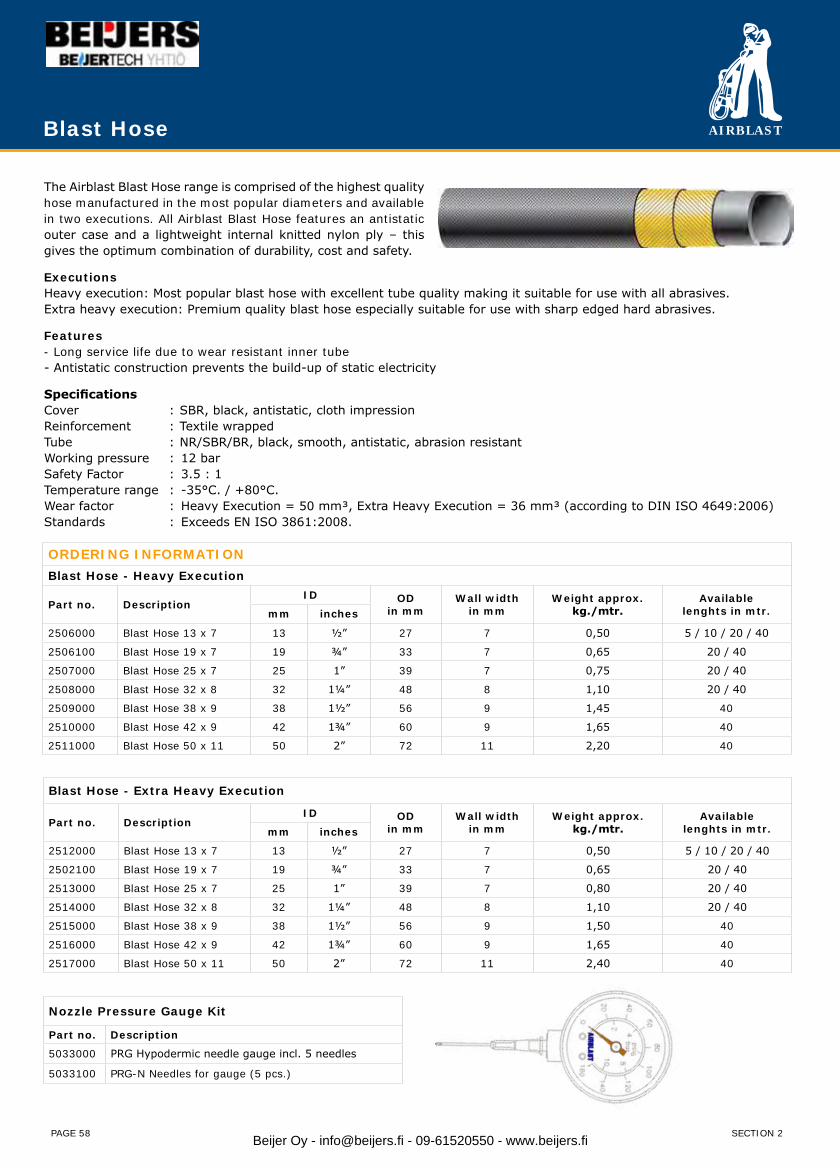
AIRBLAST
PAGE 58
The Airblast Blast Hose range is comprised of the highest quality hose manufactured in the most popular diameters and available in two executions. All Airblast Blast Hose features an antistatic outer case and a lightweight internal knitted nylon ply – this gives the optimum combination of durability, cost and safety.
ExecutionsHeavy execution: Most popular blast hose with excellent tube quality making it suitable for use with all abrasives.Extra heavy execution: Premium quality blast hose especially suitable for use with sharp edged hard abrasives.
Features- Long service life due to wear resistant inner tube- Antistatic construction prevents the build-up of static electricity
SpecificationsCover : SBR, black, antistatic, cloth impressionReinforcement : Textile wrappedTube : NR/SBR/BR, black, smooth, antistatic, abrasion resistantWorking pressure : 12 barSafety Factor : 3.5 : 1Temperature range : -35°C. / +80°C.Wear factor : Heavy Execution = 50 mm³, Extra Heavy Execution = 36 mm³ (according to DIN ISO 4649:2006)Standards : Exceeds EN ISO 3861:2008.
ORDERING INFORMATIONBlast Hose - Heavy Execution
Part no. DescriptionID OD
in mmWall width
in mmWeight approx.
kg./mtr.Available
lenghts in mtr.mm inches
2506000 Blast Hose 13 x 7 13 ½” 27 7 0,50 5 / 10 / 20 / 40
2506100 Blast Hose 19 x 7 19 ¾” 33 7 0,65 20 / 40
2507000 Blast Hose 25 x 7 25 1” 39 7 0,75 20 / 40
2508000 Blast Hose 32 x 8 32 1¼” 48 8 1,10 20 / 40
2509000 Blast Hose 38 x 9 38 1½” 56 9 1,45 40
2510000 Blast Hose 42 x 9 42 1¾” 60 9 1,65 40
2511000 Blast Hose 50 x 11 50 2” 72 11 2,20 40
Blast Hose - Extra Heavy Execution
Part no. DescriptionID OD
in mmWall width
in mmWeight approx.
kg./mtr.Available
lenghts in mtr.mm inches
2512000 Blast Hose 13 x 7 13 ½” 27 7 0,50 5 / 10 / 20 / 40
2502100 Blast Hose 19 x 7 19 ¾” 33 7 0,65 20 / 40
2513000 Blast Hose 25 x 7 25 1” 39 7 0,80 20 / 40
2514000 Blast Hose 32 x 8 32 1¼” 48 8 1,10 20 / 40
2515000 Blast Hose 38 x 9 38 1½” 56 9 1,50 40
2516000 Blast Hose 42 x 9 42 1¾” 60 9 1,65 40
2517000 Blast Hose 50 x 11 50 2” 72 11 2,40 40
Blast Hose
SECTION 2
Nozzle Pressure Gauge Kit
Part no. Description
5033000 PRG Hypodermic needle gauge incl. 5 needles
5033100 PRG-N Needles for gauge (5 pcs.)
Beijer Oy - [email protected] - 09-61520550 - www.beijers.fi
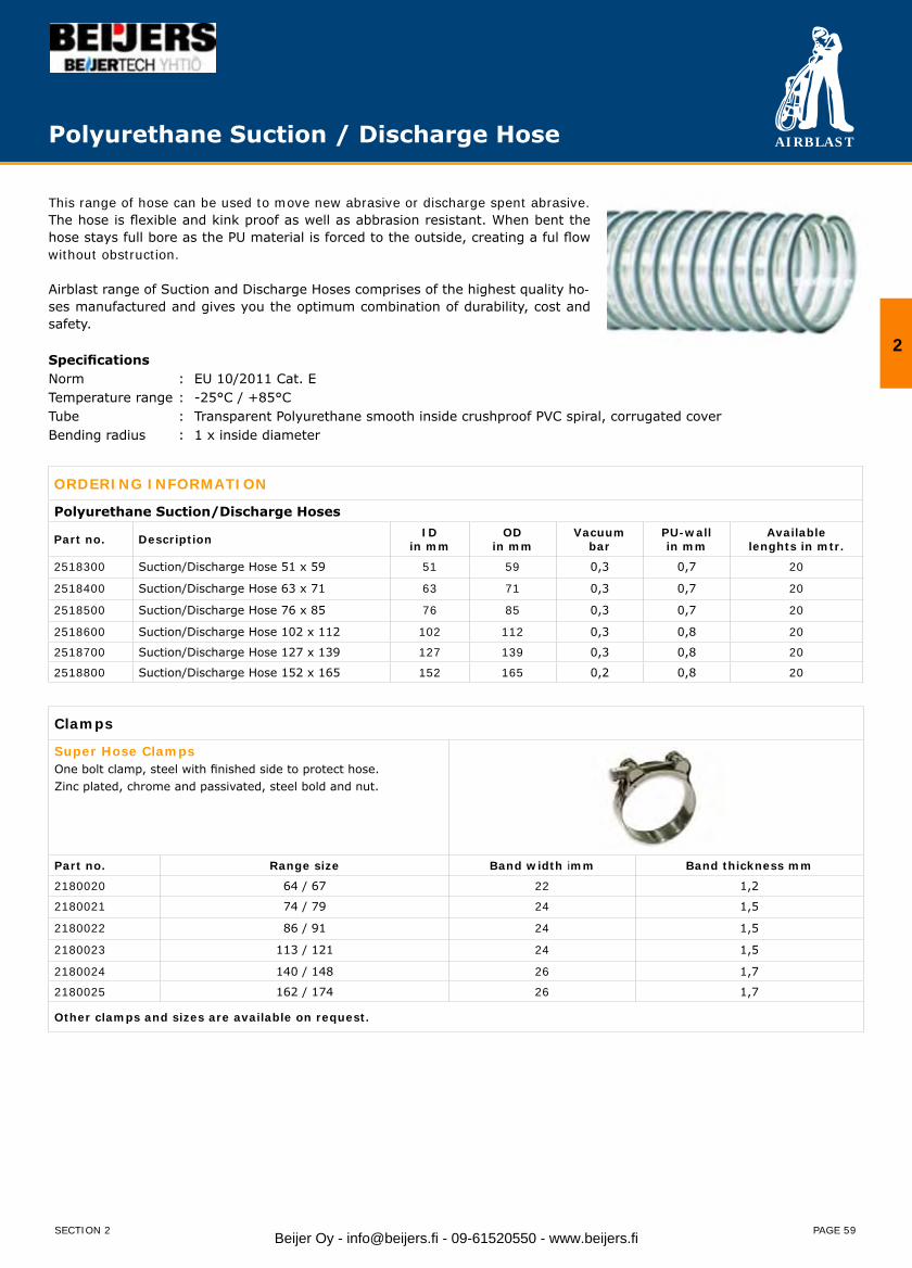
AIRBLAST
PAGE 59
This range of hose can be used to move new abrasive or discharge spent abrasive.The hose is flexible and kink proof as well as abbrasion resistant. When bent the hose stays full bore as the PU material is forced to the outside, creating a ful flow without obstruction.
Airblast range of Suction and Discharge Hoses comprises of the highest quality ho-ses manufactured and gives you the optimum combination of durability, cost and safety.
SpecificationsNorm : EU 10/2011 Cat. ETemperature range : -25°C / +85°CTube : Transparent Polyurethane smooth inside crushproof PVC spiral, corrugated cover Bending radius : 1 x inside diameter
ORDERING INFORMATION
Polyurethane Suction/Discharge Hoses
Part no. Description IDin mm
ODin mm
Vacuumbar
PU-wallin mm
Availablelenghts in mtr.
2518300 Suction/Discharge Hose 51 x 59 51 59 0,3 0,7 20
2518400 Suction/Discharge Hose 63 x 71 63 71 0,3 0,7 20
2518500 Suction/Discharge Hose 76 x 85 76 85 0,3 0,7 20
2518600 Suction/Discharge Hose 102 x 112 102 112 0,3 0,8 20
2518700 Suction/Discharge Hose 127 x 139 127 139 0,3 0,8 20
2518800 Suction/Discharge Hose 152 x 165 152 165 0,2 0,8 20
Clamps
Super Hose ClampsOne bolt clamp, steel with finished side to protect hose.Zinc plated, chrome and passivated, steel bold and nut.
Part no. Range size Band width imm Band thickness mm
2180020 64 / 67 22 1,2
2180021 74 / 79 24 1,5
2180022 86 / 91 24 1,5
2180023 113 / 121 24 1,5
2180024 140 / 148 26 1,7
2180025 162 / 174 26 1,7
Other clamps and sizes are available on request.
Polyurethane Suction / Discharge Hose
2
SECTION 2 Beijer Oy - [email protected] - 09-61520550 - www.beijers.fi

AIRBLAST
PAGE 60
Airblast range of Suction and Discharge Hoses comprises of the highest quality hoses manufactured and gives you the optimum combination of durability, cost and safety.
Rubber Hose Suction hose for shotblast, pebbles, mud, sand etc. Also for suction/discharge of other abrasives. High abrasive resistant tube. Light and flexible construction.
Specifications:
Working pressure : 1 barBurst pressure : 2,5 barVacuum : 0,9 barTemperature range : -25°C / +70°CWear resistance : 75 mm³ according to DIN 53516Tube : NR/SBR, smoothCover : SBR, black, corrugated, fabric finishReinforcements : textile plies, static-wire steel spiralBending radius : 2.5 x inside diameter
Rubber Suction & Discharge Hose
ORDERING INFORMATION
Rubber Suction/Discharge Hoses
Part no. Description IDin mm
ODin mm
Wall widthin mm
Availablelenghts in mtr.
8069717 Suction/Discharge Hose 51 x 60 51 60 4,5 20
8069708 Suction/Discharge Hose 63 x 72 63 72 4,5 20
8069718 Suction/Discharge Hose 76 x 85 76 85 4,5 20
8069709 Suction/Discharge Hose 102 x 112 102 112 5 20
8069719 Suction/Discharge Hose 127 x 137 127 137 5 20
8069710 Suction/Discharge Hose 152 x 164 152 164 6 20
Couplings
Female coupling for hoseclamp assembly, System “Perrot”.Hot dip galvanized steel with handle. SBR seal.Handle with all sizes fixed except 8” will be seperatedand interchangable.
Male coupling for hose-clamp assembly, System “Bauer”.Hot dip galvanized steel. With hose tail, ball and lever closure ring.
Part no. Size For hose inner Ø mm Part no. Size For hose inner
Ø mm
2180001 50 / 50 51 2180010 50 / 50 51
2180002 89 / 75 76 2180011 89 / 75 76
2180003 108 / 100 102 2180012 108 / 100 102
2180004 133 / 125 125 2180013 133 / 125 125
2180005 159 / 150 152 2180014 159 / 150 152
For hose clamps see page 59.
SECTION 2Beijer Oy - [email protected] - 09-61520550 - www.beijers.fi
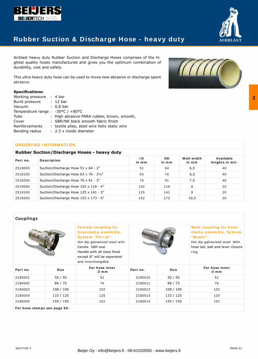
AIRBLAST
PAGE 61
Rubber Suction & Discharge Hose - heavy duty
2
SECTION 2
Airblast heavy duty Rubber Suction and Discharge Hoses comprises of the hi-ghest quality hoses manufactured and gives you the optimum combination of durability, cost and safety.
This ultra heavy duty hose can be used to move new abrasive or discharge spent abrasive.
Specifications:Working pressure : 4 barBurst pressure : 12 barVacuum : 0,8 barTemperature range : -30°C / +80°CTube : High abrasive PARA rubber, brown, smooth,Cover : SBR/NR black smooth fabric finishReinforcements : textile plies, steel wire helix static wireBending radius : 2.5 x inside diameter
ORDERING INFORMATION
Rubber Suction/Discharge Hoses - heavy duty
Part no. Description IDin mm
ODin mm
Wall widthin mm
Availablelenghts in mtr.
2518000 Suction/Discharge Hose 51 x 64 - 2” 51 64 6,5 40
2518100 Suction/Discharge Hose 63 x 76 - 2½” 63 76 6,5 40
2518200 Suction/Discharge Hose 76 x 91 - 3” 76 91 7,5 40
2519000 Suction/Discharge Hose 102 x 118 - 4” 102 118 8 20
2519100 Suction/Discharge Hose 125 x 141 - 5” 125 141 8 20
2519200 Suction/Discharge Hose 152 x 173 - 6” 152 173 10,5 20
Couplings
Female coupling for hoseclamp assembly, System “Perrot”.Hot dip galvanized steel with handle. SBR seal.Handle with all sizes fixed except 8” will be seperatedand interchangable.
Male coupling for hose-clamp assembly, System “Bauer”.Hot dip galvanized steel. With hose tail, ball and lever closure ring.
Part no. Size For hose inner Ø mm Part no. Size For hose inner
Ø mm
2180001 50 / 50 51 2180010 50 / 50 51
2180002 89 / 75 76 2180011 89 / 75 76
2180003 108 / 100 102 2180012 108 / 100 102
2180004 133 / 125 125 2180013 133 / 125 125
2180005 159 / 150 152 2180014 159 / 150 152
For hose clamps see page 59.
Beijer Oy - [email protected] - 09-61520550 - www.beijers.fi
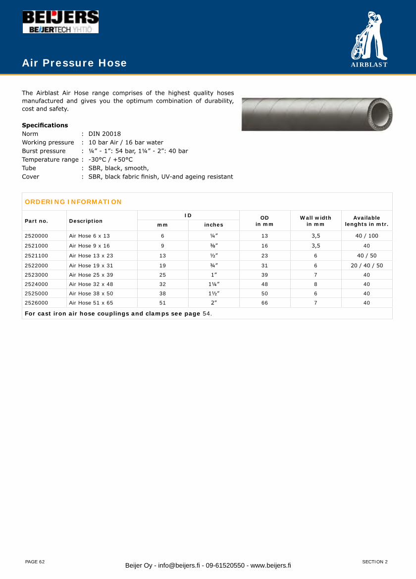
AIRBLAST
PAGE 62
The Airblast Air Hose range comprises of the highest quality hoses manufactured and gives you the optimum combination of durability, cost and safety.
SpecificationsNorm : DIN 20018Working pressure : 10 bar Air / 16 bar waterBurst pressure : ¼” - 1”: 54 bar, 1¼” - 2”: 40 barTemperature range : -30°C / +50°CTube : SBR, black, smooth,Cover : SBR, black fabric finish, UV-and ageing resistant
ORDERING INFORMATION
Part no. DescriptionID OD
in mmWall width
in mmAvailable
lenghts in mtr.mm inches
2520000 Air Hose 6 x 13 6 ¼” 13 3,5 40 / 100
2521000 Air Hose 9 x 16 9 ⅜” 16 3,5 40
2521100 Air Hose 13 x 23 13 ½” 23 6 40 / 50
2522000 Air Hose 19 x 31 19 ¾” 31 6 20 / 40 / 50
2523000 Air Hose 25 x 39 25 1” 39 7 40
2524000 Air Hose 32 x 48 32 1¼” 48 8 40
2525000 Air Hose 38 x 50 38 1½” 50 6 40
2526000 Air Hose 51 x 65 51 2” 66 7 40
For cast iron air hose couplings and clamps see page 54.
Air Pressure Hose
SECTION 2Beijer Oy - [email protected] - 09-61520550 - www.beijers.fi
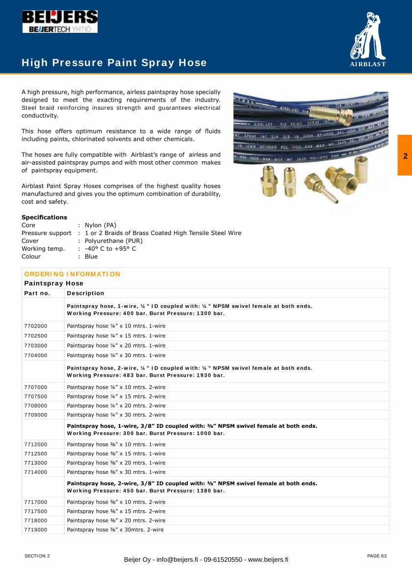
AIRBLAST
PAGE 63
High Pressure Paint Spray Hose
A high pressure, high performance, airless paintspray hose specially designed to meet the exacting requirements of the industry. Steel braid reinforcing insures strength and guarantees electrical conductivity.
This hose offers optimum resistance to a wide range of fluids including paints, chlorinated solvents and other chemicals.
The hoses are fully compatible with Airblast’s range of airless and air-assisted paintspray pumps and with most other common makes of paintspray equipment.
Airblast Paint Spray Hoses comprises of the highest quality hoses manufactured and gives you the optimum combination of durability, cost and safety.
SpecificationsCore : Nylon (PA)Pressure support : 1 or 2 Braids of Brass Coated High Tensile Steel WireCover : Polyurethane (PUR)Working temp. : -40° C to +95° CColour : Blue
ORDERING INFORMATIONPaintspray HosePart no. Description
Paintspray hose, 1-wire, ¼” ID coupled with: ¼” NPSM swivel female at both ends.Working Pressure: 400 bar. Burst Pressure: 1300 bar.
7702000 Paintspray hose ¼” x 10 mtrs. 1-wire
7702500 Paintspray hose ¼” x 15 mtrs. 1-wire
7703000 Paintspray hose ¼” x 20 mtrs. 1-wire
7704000 Paintspray hose ¼” x 30 mtrs. 1-wire
Paintspray hose, 2-wire, ¼” ID coupled with: ¼” NPSM swivel female at both ends.Working Pressure: 483 bar. Burst Pressure: 1930 bar.
7707000 Paintspray hose ¼” x 10 mtrs. 2-wire
7707500 Paintspray hose ¼” x 15 mtrs. 2-wire
7708000 Paintspray hose ¼” x 20 mtrs. 2-wire
7709000 Paintspray hose ¼” x 30 mtrs. 2-wire
Paintspray hose, 1-wire, 3/8” ID coupled with: ⅜” NPSM swivel female at both ends.Working Pressure: 300 bar. Burst Pressure: 1000 bar.
7712000 Paintspray hose ⅜” x 10 mtrs. 1-wire
7712500 Paintspray hose ⅜” x 15 mtrs. 1-wire
7713000 Paintspray hose ⅜” x 20 mtrs. 1-wire
7714000 Paintspray hose ⅜” x 30 mtrs. 1-wire
Paintspray hose, 2-wire, 3/8” ID coupled with: ⅜” NPSM swivel female at both ends.Working Pressure: 450 bar. Burst Pressure: 1380 bar.
7717000 Paintspray hose ⅜” x 10 mtrs. 2-wire
7717500 Paintspray hose ⅜” x 15 mtrs. 2-wire
7718000 Paintspray hose ⅜” x 20 mtrs. 2-wire
7719000 Paintspray hose ⅜” x 30mtrs. 2-wire
2
SECTION 2 Beijer Oy - [email protected] - 09-61520550 - www.beijers.fi
AIRBLAST
PAGE 65
Pipe Blasting & CoatingProduct PageMiniblast 66Circleblast internal pipe blasters 67Spinnerblast internal pipe blasters 69Jumbo internal pipe blasters 71Pipecoater-I internal pipe coater 73Pipecoater-II internal pipe coater 75Pipecoater-III/125 internal pipe coater 77Pipecoater-III/300 internal pipe coater 79Pipecoater-III/900 internal pipe coater 81Pipecoater-IV internal pipe coater 83Semi-automatic winch system 85
Section 3 - Pipe Blasting & Coating
3
SECTION 3 Beijer Oy - [email protected] - 09-61520550 - www.beijers.fi
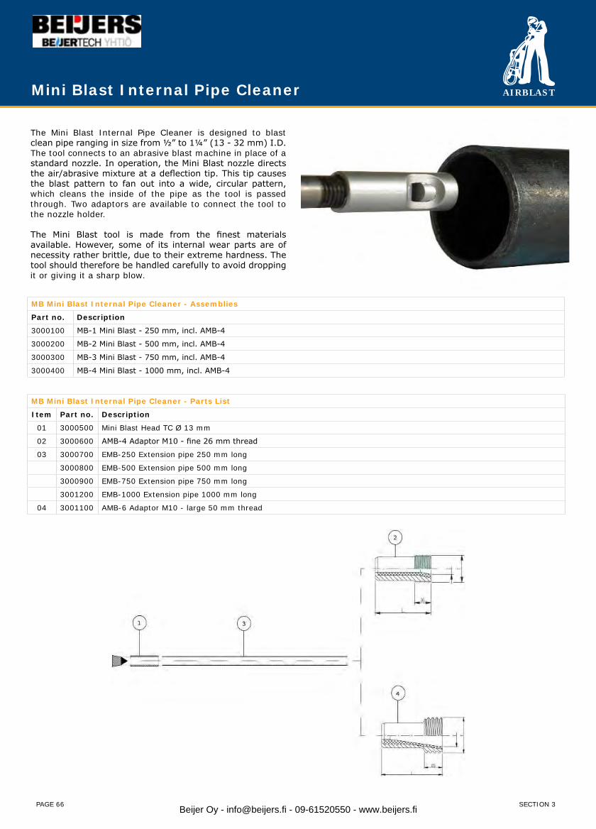
AIRBLAST
PAGE 66
Mini Blast Internal Pipe Cleaner
The Mini Blast Internal Pipe Cleaner is designed to blast clean pipe ranging in size from ½” to 1¼” (13 - 32 mm) I.D. The tool connects to an abrasive blast machine in place of a standard nozzle. In operation, the Mini Blast nozzle directs the air/abrasive mixture at a deflection tip. This tip causes the blast pattern to fan out into a wide, circular pattern, which cleans the inside of the pipe as the tool is passed through. Two adaptors are available to connect the tool to the nozzle holder.
The Mini Blast tool is made from the finest materials available. However, some of its internal wear parts are of necessity rather brittle, due to their extreme hardness. The tool should therefore be handled carefully to avoid dropping it or giving it a sharp blow.
MB Mini Blast Internal Pipe Cleaner - Assemblies
Part no. Description
3000100 MB-1 Mini Blast - 250 mm, incl. AMB-4
3000200 MB-2 Mini Blast - 500 mm, incl. AMB-4
3000300 MB-3 Mini Blast - 750 mm, incl. AMB-4
3000400 MB-4 Mini Blast - 1000 mm, incl. AMB-4
MB Mini Blast Internal Pipe Cleaner - Parts List
Item Part no. Description
01 3000500 Mini Blast Head TC Ø 13 mm
02 3000600 AMB-4 Adaptor M10 - fine 26 mm thread
03 3000700 EMB-250 Extension pipe 250 mm long
3000800 EMB-500 Extension pipe 500 mm long
3000900 EMB-750 Extension pipe 750 mm long
3001200 EMB-1000 Extension pipe 1000 mm long
04 3001100 AMB-6 Adaptor M10 - large 50 mm thread
SECTION 3Beijer Oy - [email protected] - 09-61520550 - www.beijers.fi
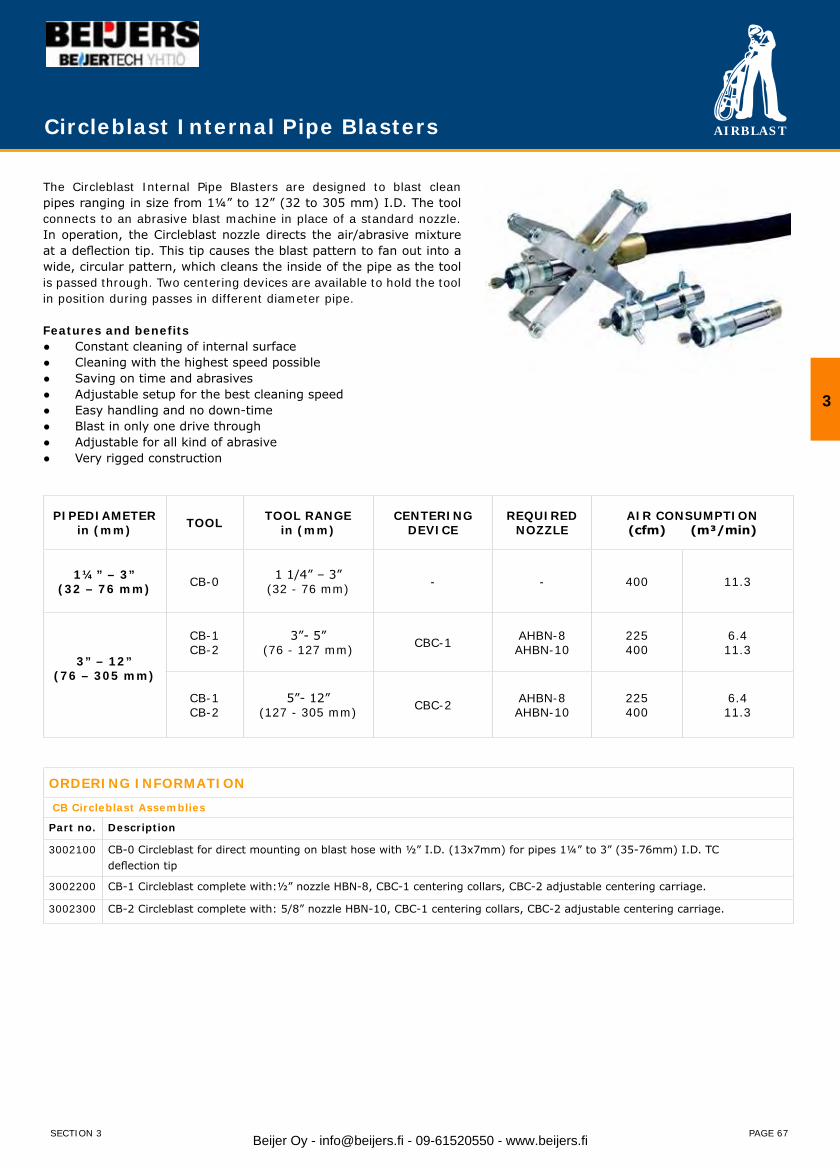
AIRBLAST
PAGE 67
Circleblast Internal Pipe Blasters
The Circleblast Internal Pipe Blasters are designed to blast clean pipes ranging in size from 1¼” to 12” (32 to 305 mm) I.D. The tool connects to an abrasive blast machine in place of a standard nozzle. In operation, the Circleblast nozzle directs the air/abrasive mixture at a deflection tip. This tip causes the blast pattern to fan out into a wide, circular pattern, which cleans the inside of the pipe as the tool is passed through. Two centering devices are available to hold the tool in position during passes in different diameter pipe.
Features and benefits● Constant cleaning of internal surface● Cleaning with the highest speed possible● Saving on time and abrasives● Adjustable setup for the best cleaning speed● Easy handling and no down-time● Blast in only one drive through● Adjustable for all kind of abrasive● Very rigged construction
PIPEDIAMETERin (mm) TOOL TOOL RANGE
in (mm)CENTERING
DEVICEREQUIRED
NOZZLEAIR CONSUMPTION(cfm) (m³/min)
1¼” – 3”(32 – 76 mm) CB-0 1 1/4” – 3”
(32 - 76 mm) - - 400 11.3
3” – 12”(76 – 305 mm)
CB-1 CB-2
3”- 5”(76 - 127 mm) CBC-1 AHBN-8
AHBN-10225400
6.411.3
CB-1 CB-2
5”- 12”(127 - 305 mm) CBC-2 AHBN-8
AHBN-10225400
6.411.3
ORDERING INFORMATION
CB Circleblast Assemblies
Part no. Description
3002100 CB-0 Circleblast for direct mounting on blast hose with ½” I.D. (13x7mm) for pipes 1¼” to 3” (35-76mm) I.D. TC deflection tip
3002200 CB-1 Circleblast complete with:½” nozzle HBN-8, CBC-1 centering collars, CBC-2 adjustable centering carriage.
3002300 CB-2 Circleblast complete with: 5/8” nozzle HBN-10, CBC-1 centering collars, CBC-2 adjustable centering carriage.
3
SECTION 3 Beijer Oy - [email protected] - 09-61520550 - www.beijers.fi
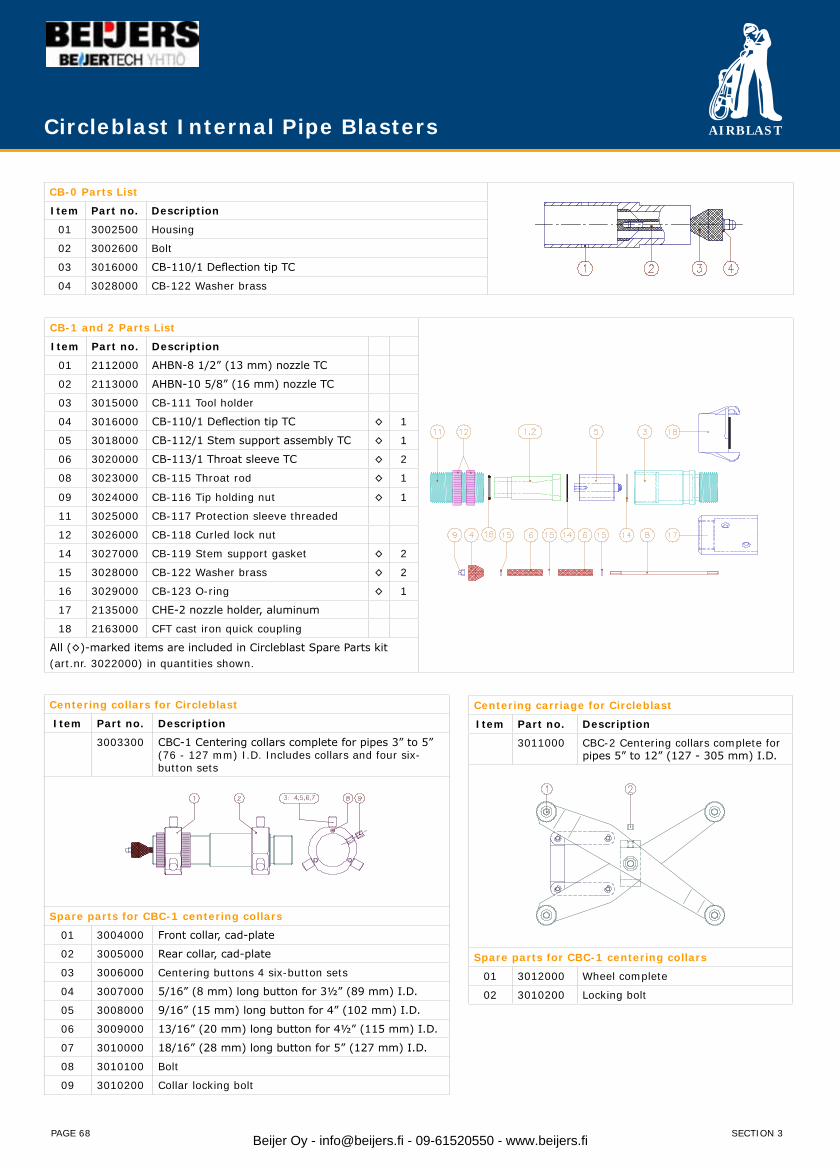
AIRBLAST
PAGE 68
Circleblast Internal Pipe Blasters
CB-0 Parts List Item Part no. Description
01 3002500 Housing
02 3002600 Bolt
03 3016000 CB-110/1 Deflection tip TC
04 3028000 CB-122 Washer brass
CB-1 and 2 Parts List
Item Part no. Description
01 2112000 AHBN-8 1/2” (13 mm) nozzle TC
02 2113000 AHBN-10 5/8” (16 mm) nozzle TC
03 3015000 CB-111 Tool holder
04 3016000 CB-110/1 Deflection tip TC ◊ 1
05 3018000 CB-112/1 Stem support assembly TC ◊ 1
06 3020000 CB-113/1 Throat sleeve TC ◊ 2
08 3023000 CB-115 Throat rod ◊ 1
09 3024000 CB-116 Tip holding nut ◊ 1
11 3025000 CB-117 Protection sleeve threaded
12 3026000 CB-118 Curled lock nut
14 3027000 CB-119 Stem support gasket ◊ 2
15 3028000 CB-122 Washer brass ◊ 2
16 3029000 CB-123 O-ring ◊ 1
17 2135000 CHE-2 nozzle holder, aluminum
18 2163000 CFT cast iron quick coupling
All (◊)-marked items are included in Circleblast Spare Parts kit(art.nr. 3022000) in quantities shown.
Centering collars for Circleblast
Item Part no. Description
3003300 CBC-1 Centering collars complete for pipes 3” to 5” (76 - 127 mm) I.D. Includes collars and four six-button sets
Spare parts for CBC-1 centering collars
01 3004000 Front collar, cad-plate
02 3005000 Rear collar, cad-plate
03 3006000 Centering buttons 4 six-button sets
04 3007000 5/16” (8 mm) long button for 3½” (89 mm) I.D.
05 3008000 9/16” (15 mm) long button for 4” (102 mm) I.D.
06 3009000 13/16” (20 mm) long button for 4½” (115 mm) I.D.
07 3010000 18/16” (28 mm) long button for 5” (127 mm) I.D.
08 3010100 Bolt
09 3010200 Collar locking bolt
Centering carriage for Circleblast
Item Part no. Description
3011000 CBC-2 Centering collars complete for pipes 5” to 12” (127 - 305 mm) I.D.
Spare parts for CBC-1 centering collars
01 3012000 Wheel complete
02 3010200 Locking bolt
SECTION 3Beijer Oy - [email protected] - 09-61520550 - www.beijers.fi
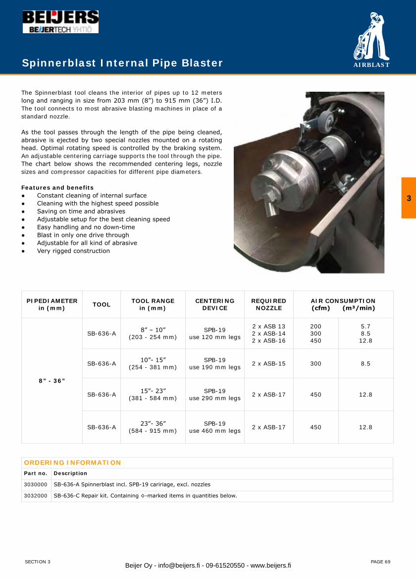
AIRBLAST
PAGE 69
The Spinnerblast tool cleans the interior of pipes up to 12 meters long and ranging in size from 203 mm (8”) to 915 mm (36”) I.D. The tool connects to most abrasive blasting machines in place of a standard nozzle.
As the tool passes through the length of the pipe being cleaned, abrasive is ejected by two special nozzles mounted on a rotating head. Optimal rotating speed is controlled by the braking system. An adjustable centering carriage supports the tool through the pipe. The chart below shows the recommended centering legs, nozzle sizes and compressor capacities for different pipe diameters.
Features and benefits● Constant cleaning of internal surface● Cleaning with the highest speed possible● Saving on time and abrasives● Adjustable setup for the best cleaning speed● Easy handling and no down-time● Blast in only one drive through● Adjustable for all kind of abrasive● Very rigged construction
PIPEDIAMETERin (mm) TOOL TOOL RANGE
in (mm)CENTERING
DEVICEREQUIRED
NOZZLEAIR CONSUMPTION(cfm) (m³/min)
8” - 36”
SB-636-A 8” – 10”(203 - 254 mm)
SPB-19use 120 mm legs
2 x ASB 132 x ASB-142 x ASB-16
200300450
5.78.512.8
SB-636-A 10”- 15”(254 - 381 mm)
SPB-19use 190 mm legs 2 x ASB-15 300 8.5
SB-636-A 15”- 23”(381 - 584 mm)
SPB-19use 290 mm legs 2 x ASB-17 450 12.8
SB-636-A 23”- 36”(584 - 915 mm)
SPB-19use 460 mm legs 2 x ASB-17 450 12.8
ORDERING INFORMATIONPart no. Description
3030000 SB-636-A Spinnerblast incl. SPB-19 caririage, excl. nozzles
3032000 SB-636-C Repair kit. Containing ◊-marked items in quantities below.
Spinnerblast Internal Pipe Blaster
3
SECTION 3 Beijer Oy - [email protected] - 09-61520550 - www.beijers.fi
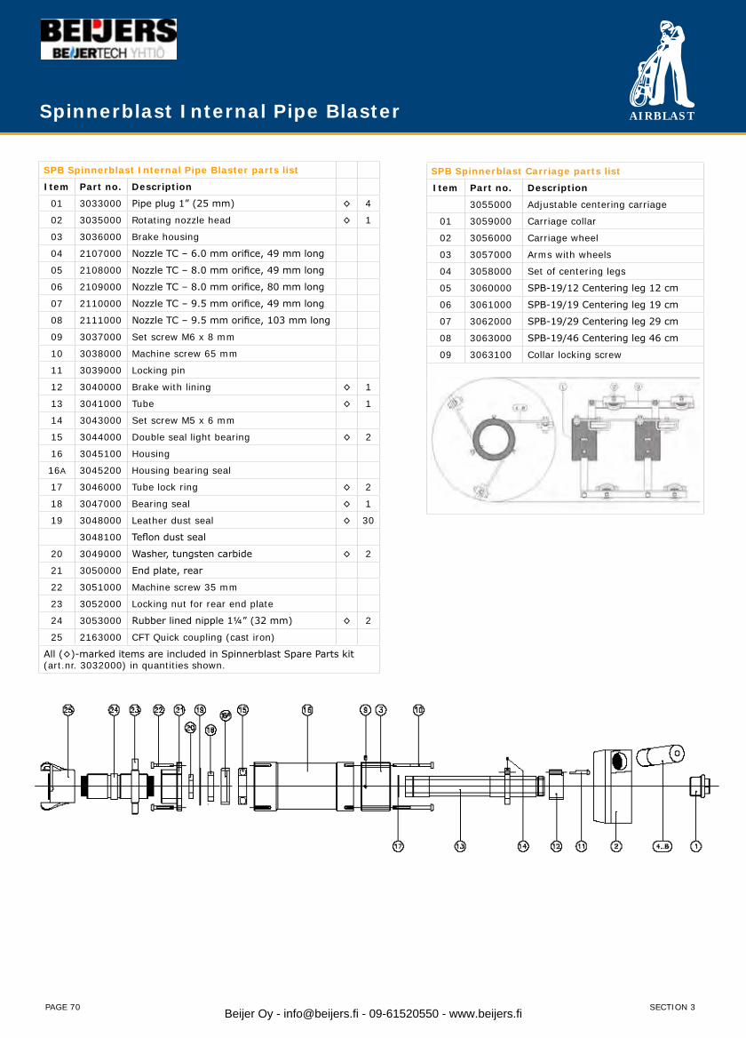
AIRBLAST
PAGE 70
Spinnerblast Internal Pipe Blaster
SPB Spinnerblast Internal Pipe Blaster parts list
Item Part no. Description
01 3033000 Pipe plug 1” (25 mm) ◊ 4
02 3035000 Rotating nozzle head ◊ 1
03 3036000 Brake housing
04 2107000 Nozzle TC – 6.0 mm orifice, 49 mm long
05 2108000 Nozzle TC – 8.0 mm orifice, 49 mm long
06 2109000 Nozzle TC – 8.0 mm orifice, 80 mm long
07 2110000 Nozzle TC – 9.5 mm orifice, 49 mm long
08 2111000 Nozzle TC – 9.5 mm orifice, 103 mm long
09 3037000 Set screw M6 x 8 mm
10 3038000 Machine screw 65 mm
11 3039000 Locking pin
12 3040000 Brake with lining ◊ 1
13 3041000 Tube ◊ 1
14 3043000 Set screw M5 x 6 mm
15 3044000 Double seal light bearing ◊ 2
16 3045100 Housing
16A 3045200 Housing bearing seal
17 3046000 Tube lock ring ◊ 2
18 3047000 Bearing seal ◊ 1
19 3048000 Leather dust seal ◊ 30
3048100 Teflon dust seal
20 3049000 Washer, tungsten carbide ◊ 2
21 3050000 End plate, rear
22 3051000 Machine screw 35 mm
23 3052000 Locking nut for rear end plate
24 3053000 Rubber lined nipple 1¼” (32 mm) ◊ 2
25 2163000 CFT Quick coupling (cast iron)
All (◊)-marked items are included in Spinnerblast Spare Parts kit(art.nr. 3032000) in quantities shown.
SPB Spinnerblast Carriage parts list
Item Part no. Description
3055000 Adjustable centering carriage
01 3059000 Carriage collar
02 3056000 Carriage wheel
03 3057000 Arms with wheels
04 3058000 Set of centering legs
05 3060000 SPB-19/12 Centering leg 12 cm
06 3061000 SPB-19/19 Centering leg 19 cm
07 3062000 SPB-19/29 Centering leg 29 cm
08 3063000 SPB-19/46 Centering leg 46 cm
09 3063100 Collar locking screw
SECTION 3Beijer Oy - [email protected] - 09-61520550 - www.beijers.fi

AIRBLAST
PAGE 71
Jumbo Internal Pipe Blaster
The Jumbo Internal Pipe Blaster tool cleans the interior of pipes up to 12 meter long and ranging in size from 890 mm (35”) to 1600 mm (63”) I.D. The tool connects to most abrasive blasting machines in place of a standard nozzle. As the tool passes through the length of the pipe being cleaned, abrasive is ejected by two special nozzles mounted on a rotating head. Optimal rotating speed is controlled by the braking system. An adjustable centering carriage supports the tool through the pipe.
Features and benefits● Constant cleaning of internal surface● Cleaning with the highest speed possible● Saving on time and abrasives● Adjustable setup for the best cleaning speed● Easy handling and no down-time● Blast in only one drive through● Adjustable for all kind of abrasive● Very rigged construction
ORDERING INFORMATIONPart no. Description
3400000 JPB-I Jumbo incl. carriage, excl. nozzles
3410000 JPB-C Repair kit. Containing ◊-marked items in quantities part list.
Jumbo Internal Pipe Blaster - nozzles
Part no. Description
2007000 ATSDX-4 Tungsten Carbide long venturi nozzle, 6.5 mm orifice, length 135 mm, 1¼” (32 mm) inlet and fine thread
2008000 ATSDX-5 Tungsten Carbide long venturi nozzle, 8.0 mm orifice, length 135 mm, 1¼” (32 mm) inlet and fine thread
2009000 ATSDX-6 Tungsten Carbide long venturi nozzle, 9.5 mm orifice, length 135 mm, 1¼” (32 mm) inlet and fine thread
3
SECTION 3 Beijer Oy - [email protected] - 09-61520550 - www.beijers.fi
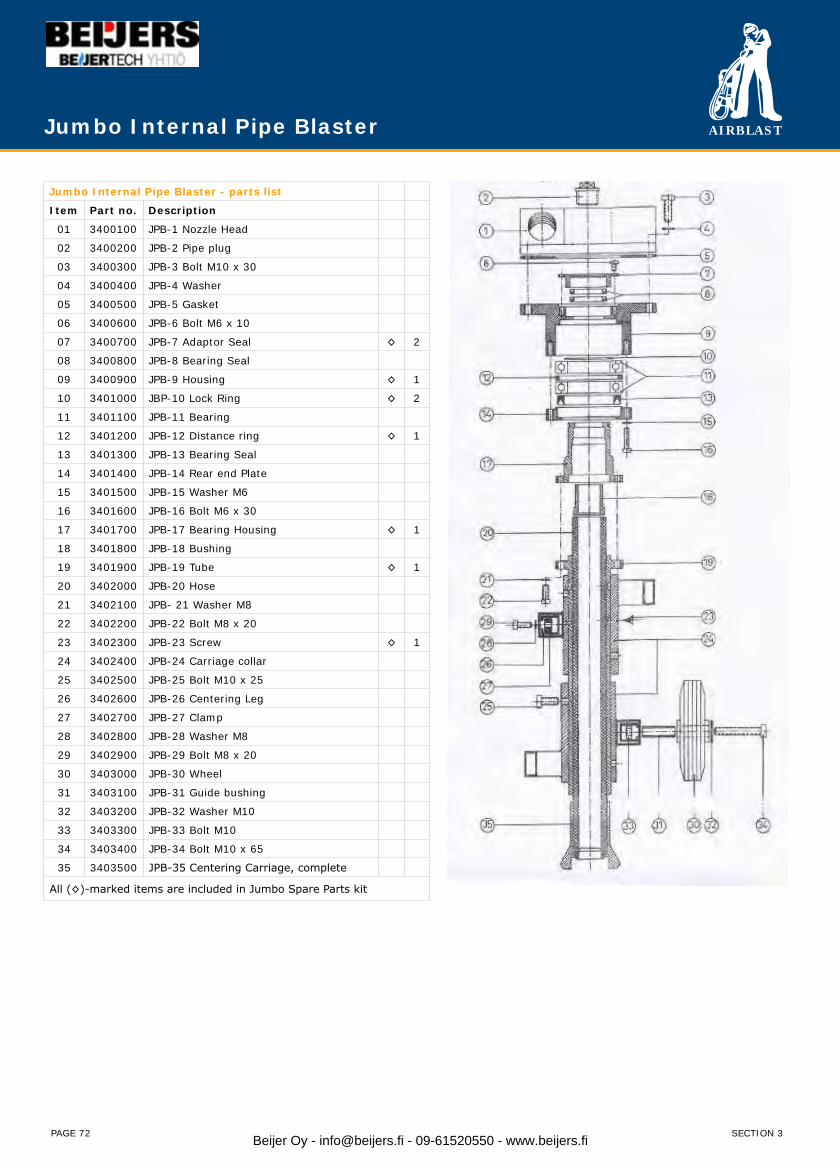
AIRBLAST
PAGE 72
Jumbo Internal Pipe Blaster
Jumbo Internal Pipe Blaster - parts list
Item Part no. Description
01 3400100 JPB-1 Nozzle Head
02 3400200 JPB-2 Pipe plug
03 3400300 JPB-3 Bolt M10 x 30
04 3400400 JPB-4 Washer
05 3400500 JPB-5 Gasket
06 3400600 JPB-6 Bolt M6 x 10
07 3400700 JPB-7 Adaptor Seal ◊ 2
08 3400800 JPB-8 Bearing Seal
09 3400900 JPB-9 Housing ◊ 1
10 3401000 JBP-10 Lock Ring ◊ 2
11 3401100 JPB-11 Bearing
12 3401200 JPB-12 Distance ring ◊ 1
13 3401300 JPB-13 Bearing Seal
14 3401400 JPB-14 Rear end Plate
15 3401500 JPB-15 Washer M6
16 3401600 JPB-16 Bolt M6 x 30
17 3401700 JPB-17 Bearing Housing ◊ 1
18 3401800 JPB-18 Bushing
19 3401900 JPB-19 Tube ◊ 1
20 3402000 JPB-20 Hose
21 3402100 JPB- 21 Washer M8
22 3402200 JPB-22 Bolt M8 x 20
23 3402300 JPB-23 Screw ◊ 1
24 3402400 JPB-24 Carriage collar
25 3402500 JPB-25 Bolt M10 x 25
26 3402600 JPB-26 Centering Leg
27 3402700 JPB-27 Clamp
28 3402800 JPB-28 Washer M8
29 3402900 JPB-29 Bolt M8 x 20
30 3403000 JPB-30 Wheel
31 3403100 JPB-31 Guide bushing
32 3403200 JPB-32 Washer M10
33 3403300 JPB-33 Bolt M10
34 3403400 JPB-34 Bolt M10 x 65
35 3403500 JPB-35 Centering Carriage, complete
All (◊)-marked items are included in Jumbo Spare Parts kit
SECTION 3Beijer Oy - [email protected] - 09-61520550 - www.beijers.fi
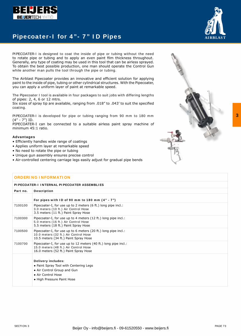
AIRBLAST
PAGE 73
PIPECOATER-I is designed to coat the inside of pipe or tubing without the need to rotate pipe or tubing and to apply an even paint film thickness throughout. Generally, any type of coating may be used in this tool that can be airless sprayed. To obtain the best possible production, one man should operate the Control Gun while another man pulls the tool through the pipe or tubing.
The Airblast Pipecoater provides an innovative and efficient solution for applying paint to the inside of pipe, tubing or other cylindrical structures. With the Pipecoater, you can apply a uniform layer of paint at remarkable speed.
The Pipecoater I tool is available in four packages to suit jobs with differing lengths of pipes: 2, 4, 6 or 12 mtrs.Six sizes of spray tip are available, ranging from .018” to .043’ to suit the specified coating.
PIPECOATER-I is developed for pipe or tubing ranging from 90 mm to 180 mm (4” - 7”) ID.PIPECOATER-I can be connected to a suitable airless paint spray machine of minimum 45:1 ratio.
Advantages• Efficiently handles wide range of coatings• Applies uniform layer at remarkable speed• No need to rotate the pipe or tubing• Unique gun assembly ensures precise control• Air-controlled centering carriage legs easily adjust for gradual pipe bends
ORDERING INFORMATION
PIPECOATER-I INTERNAL PIPECOATER ASSEMBLIES
Part no. Description
For pipes with ID of 90 mm to 180 mm (4” - 7”)
7100100 Pipecoater-I, for use up to 2 meters (6 ft.) long pipe incl.:3.0 meters (10 ft.) Air Control Hose3.5 meters (11 ft.) Paint Spray Hose
7100300 Pipecoater-I, for use up to 4 meters (12 ft.) long pipe incl.:5.0 meters (16 ft.) Air Control Hose 5.5 meters (18 ft.) Paint Spray Hose
7100500 Pipecoater-I, for use up to 6 meters (20 ft.) long pipe incl.:10.0 meters (32 ft.) Air Control Hose10.5 meters (34 ft.) Paint Spray Hose
7100700 Pipecoater-I, for use up to 12 meters (40 ft.) long pipe incl.:15.0 meters (48 ft.) Air Control Hose16.0 meters (52 ft.) Paint Spray Hose
Delivery includes:● Paint Spray Tool with Centering Legs● Air Control Group and Gun● Air Control Hose● High Pressure Paint Hose
Pipecoater-I for 4”- 7” ID Pipes
3
SECTION 3 Beijer Oy - [email protected] - 09-61520550 - www.beijers.fi

AIRBLAST
PAGE 74
PIPECOATER-I HOSES
7100900 Air Control Hose 3.0 meters ( 10 ft. )
7101000 Air Control Hose 5.0 meters ( 16 ft. )
7101100 Air Control Hose 10.0 meters ( 32 ft. )
7101200 Paint Spray Hose 3.5 meters ( 11 ft. )
7101300 Paint Spray Hose 5.5 meters ( 18 ft. )
7101400 Paint Spray Hose 10.5 meters ( 34 ft. )
PIPECOATER-I FLOW CONTROL TIPS
7101500 Flow control tip 0.018” orifice
7101600 Flow control tip 0.021” orifice
7101700 Flow control tip 0.026” orifice
7101800 Flow control tip 0.031” orifice
7101900 Flow control tip 0.036” orifice
7102000 Flow control tip 0.043” orifice
PIPECOATER-I GUN ASSEMBLY
7102100 Spray gun, incl. hose adaptor assembly
7102200 Air group for spray gun
7102300 Adapter for silver gun
PIPECOATER-I REPAIR KITS AND RECOMMENDED SPARE PARTS
7112900 Wheel kit, Pipecoater-I includes 7112500, 7112600 and 7112700. (6 pcs. required)
7105000 O-ring set, Air Control Hose
7105100 O-ring set, Pipecoater-I
7111400 Strainer (2 pcs.)
7119500 Needle bearing
7118400 Paint tube
7118500 T-piece
Spray tips (sizes to be specified)
Pipecoater-I for 4”- 7” ID Pipes
SECTION 3Beijer Oy - [email protected] - 09-61520550 - www.beijers.fi
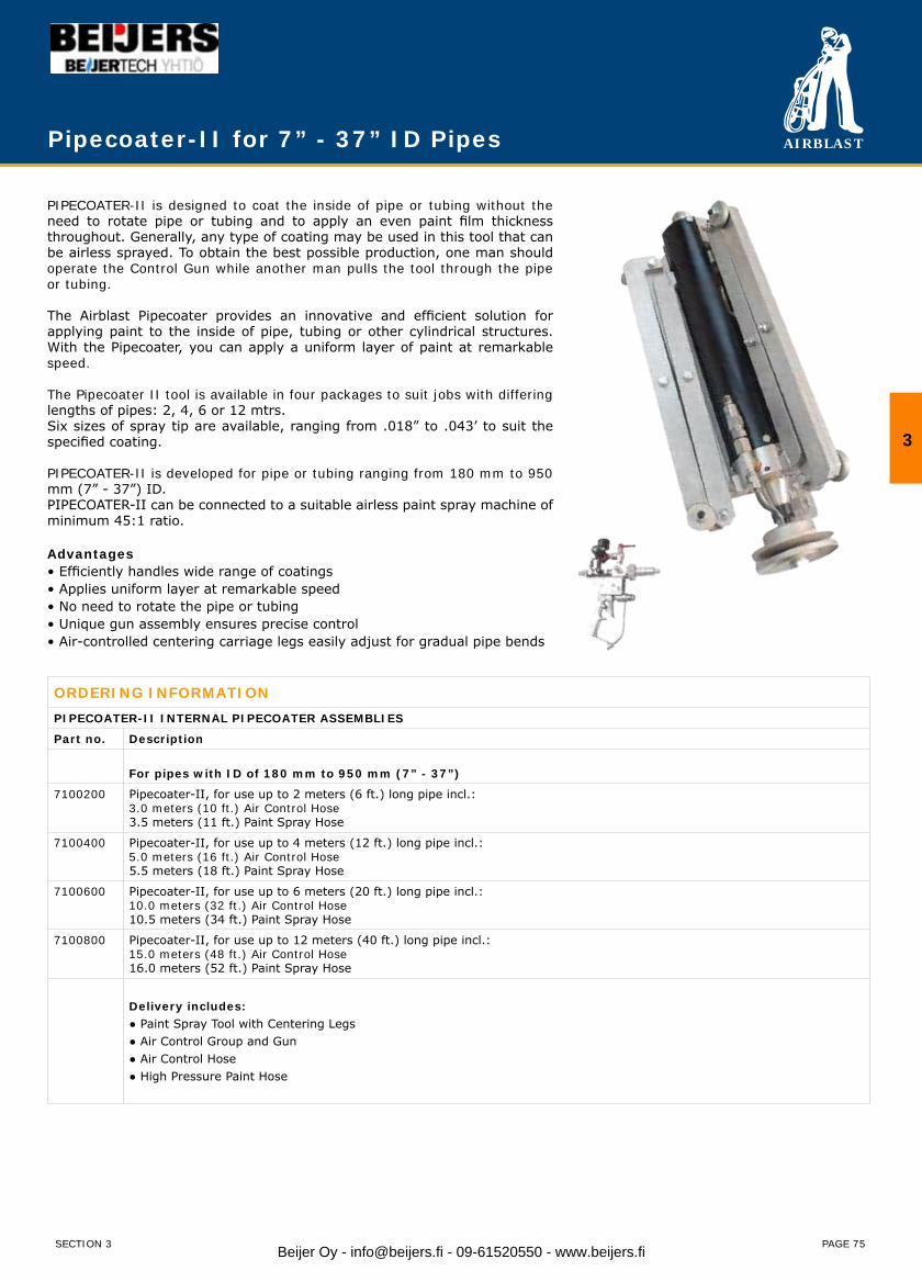
AIRBLAST
PAGE 75
PIPECOATER-II is designed to coat the inside of pipe or tubing without the need to rotate pipe or tubing and to apply an even paint film thickness throughout. Generally, any type of coating may be used in this tool that can be airless sprayed. To obtain the best possible production, one man should operate the Control Gun while another man pulls the tool through the pipe or tubing.
The Airblast Pipecoater provides an innovative and efficient solution for applying paint to the inside of pipe, tubing or other cylindrical structures. With the Pipecoater, you can apply a uniform layer of paint at remarkable speed.
The Pipecoater II tool is available in four packages to suit jobs with differing lengths of pipes: 2, 4, 6 or 12 mtrs.Six sizes of spray tip are available, ranging from .018” to .043’ to suit the specified coating.
PIPECOATER-II is developed for pipe or tubing ranging from 180 mm to 950 mm (7” - 37”) ID.PIPECOATER-II can be connected to a suitable airless paint spray machine of minimum 45:1 ratio.
Advantages• Efficiently handles wide range of coatings• Applies uniform layer at remarkable speed• No need to rotate the pipe or tubing• Unique gun assembly ensures precise control• Air-controlled centering carriage legs easily adjust for gradual pipe bends
Pipecoater-II for 7” - 37” ID Pipes
ORDERING INFORMATIONPIPECOATER-II INTERNAL PIPECOATER ASSEMBLIES
Part no. Description
For pipes with ID of 180 mm to 950 mm (7” - 37”)
7100200 Pipecoater-II, for use up to 2 meters (6 ft.) long pipe incl.:3.0 meters (10 ft.) Air Control Hose3.5 meters (11 ft.) Paint Spray Hose
7100400 Pipecoater-II, for use up to 4 meters (12 ft.) long pipe incl.:5.0 meters (16 ft.) Air Control Hose5.5 meters (18 ft.) Paint Spray Hose
7100600 Pipecoater-II, for use up to 6 meters (20 ft.) long pipe incl.:10.0 meters (32 ft.) Air Control Hose10.5 meters (34 ft.) Paint Spray Hose
7100800 Pipecoater-II, for use up to 12 meters (40 ft.) long pipe incl.:15.0 meters (48 ft.) Air Control Hose16.0 meters (52 ft.) Paint Spray Hose
Delivery includes:● Paint Spray Tool with Centering Legs● Air Control Group and Gun● Air Control Hose● High Pressure Paint Hose
3
SECTION 3 Beijer Oy - [email protected] - 09-61520550 - www.beijers.fi
AIRBLAST
PAGE 76
PIPECOATER-II HOSES
7100900 Air Control Hose 3.0 meters ( 10 ft. )
7101000 Air Control Hose 5.0 meters ( 16 ft. )
7101100 Air Control Hose 10.0 meters ( 32 ft. )
7101200 Paint Spray Hose 3.5 meters ( 11 ft. )
7101300 Paint Spray Hose 5.5 meters ( 18 ft. )
7101400 Paint Spray Hose 10.5 meters ( 34 ft. )
PIPECOATER-I FLOW CONTROL TIPS
7101500 Flow control tip 0.018” orifice
7101600 Flow control tip 0.021” orifice
7101700 Flow control tip 0.026” orifice
7101800 Flow control tip 0.031” orifice
7101900 Flow control tip 0.036” orifice
7102000 Flow control tip 0.043” orifice
PIPECOATER-II GUN ASSEMBLY
7102100 Spray gun, incl. hose adaptor assembly
7102200 Air group for spray gun
7102300 Adapter for silver gun
PIPECOATER-II REPAIR KITS AND RECOMMENDED SPARE PARTS
7119200 Rotating head kit, Pipecoater-II includes 7114600, 7118000, 7114700 and 7114800
7119300 Wheel kit, Pipecoater-II includes 7117800, 7118000, 7118100, 7118200 and 7119000
7105000 O-ring set, Air Control Hose
7105200 O-ring set, Pipecoater-II
7111400 Strainer (2 pcs.)
7113600 Blade (3 pcs.)
7114000 Bearing
7113100 Ball bearing
Spray tip (sizes to be specified)
Pipecoater-II for 7” - 37” ID Pipes
SECTION 3Beijer Oy - [email protected] - 09-61520550 - www.beijers.fi
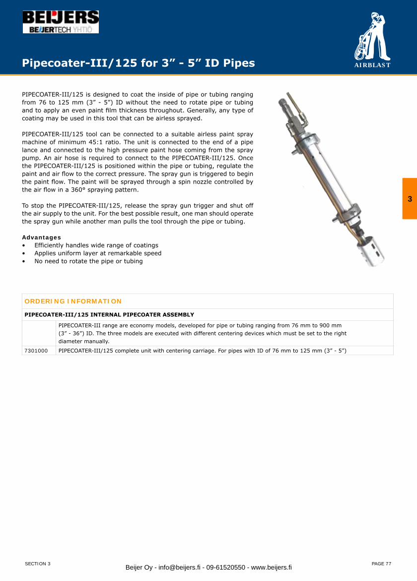
AIRBLAST
PAGE 77
Pipecoater-III/125 for 3” - 5” ID Pipes
PIPECOATER-III/125 is designed to coat the inside of pipe or tubing ranging from 76 to 125 mm (3” - 5”) ID without the need to rotate pipe or tubing and to apply an even paint film thickness throughout. Generally, any type of coating may be used in this tool that can be airless sprayed.
PIPECOATER-III/125 tool can be connected to a suitable airless paint spray machine of minimum 45:1 ratio. The unit is connected to the end of a pipe lance and connected to the high pressure paint hose coming from the spray pump. An air hose is required to connect to the PIPECOATER-III/125. Once the PIPECOATER-III/125 is positioned within the pipe or tubing, regulate the paint and air flow to the correct pressure. The spray gun is triggered to begin the paint flow. The paint will be sprayed through a spin nozzle controlled by the air flow in a 360° spraying pattern.
To stop the PIPECOATER-III/125, release the spray gun trigger and shut off the air supply to the unit. For the best possible result, one man should operate the spray gun while another man pulls the tool through the pipe or tubing.
Advantages• Efficiently handles wide range of coatings• Applies uniform layer at remarkable speed• No need to rotate the pipe or tubing
ORDERING INFORMATION
PIPECOATER-III/125 INTERNAL PIPECOATER ASSEMBLY
PIPECOATER-III range are economy models, developed for pipe or tubing ranging from 76 mm to 900 mm(3” - 36”) ID. The three models are executed with different centering devices which must be set to the rightdiameter manually.
7301000 PIPECOATER-III/125 complete unit with centering carriage. For pipes with ID of 76 mm to 125 mm (3” - 5”)
3
SECTION 3 Beijer Oy - [email protected] - 09-61520550 - www.beijers.fi
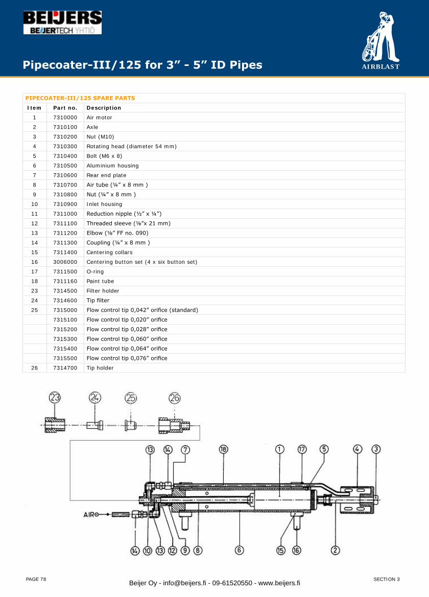
AIRBLAST
PAGE 78
Pipecoater-III/125 for 3” - 5” ID Pipes
PIPECOATER-III/125 SPARE PARTS
Item Part no. Description
1 7310000 Air motor
2 7310100 Axle
3 7310200 Nut (M10)
4 7310300 Rotating head (diameter 54 mm)
5 7310400 Bolt (M6 x 8)
6 7310500 Aluminium housing
7 7310600 Rear end plate
8 7310700 Air tube (¼” x 8 mm )
9 7310800 Nut (¼” x 8 mm )
10 7310900 Inlet housing
11 7311000 Reduction nipple (½” x ¼”)
12 7311100 Threaded sleeve (⅛”x 21 mm)
13 7311200 Elbow (⅛” FF no. 090)
14 7311300 Coupling (¼” x 8 mm )
15 7311400 Centering collars
16 3006000 Centering button set (4 x six button set)
17 7311500 O-ring
18 7311160 Paint tube
23 7314500 Filter holder
24 7314600 Tip filter
25 7315000 Flow control tip 0,042” orifice (standard)
7315100 Flow control tip 0,020” orifice
7315200 Flow control tip 0,028” orifice
7315300 Flow control tip 0,060” orifice
7315400 Flow control tip 0,064” orifice
7315500 Flow control tip 0,076” orifice
26 7314700 Tip holder
SECTION 3Beijer Oy - [email protected] - 09-61520550 - www.beijers.fi
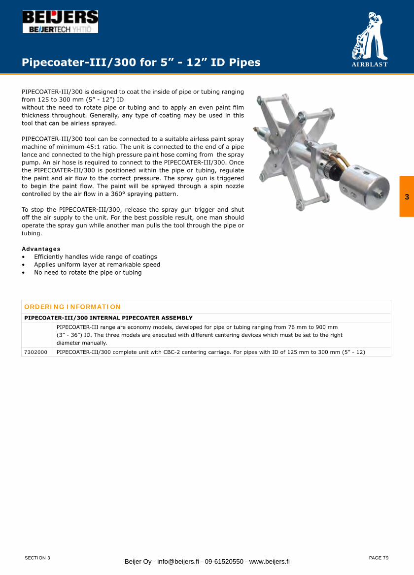
AIRBLAST
PAGE 79
PIPECOATER-III/300 is designed to coat the inside of pipe or tubing ranging from 125 to 300 mm (5” - 12”) IDwithout the need to rotate pipe or tubing and to apply an even paint film thickness throughout. Generally, any type of coating may be used in this tool that can be airless sprayed.
PIPECOATER-III/300 tool can be connected to a suitable airless paint spray machine of minimum 45:1 ratio. The unit is connected to the end of a pipe lance and connected to the high pressure paint hose coming from the spray pump. An air hose is required to connect to the PIPECOATER-III/300. Once the PIPECOATER-III/300 is positioned within the pipe or tubing, regulate the paint and air flow to the correct pressure. The spray gun is triggered to begin the paint flow. The paint will be sprayed through a spin nozzle controlled by the air flow in a 360° spraying pattern.
To stop the PIPECOATER-III/300, release the spray gun trigger and shut off the air supply to the unit. For the best possible result, one man should operate the spray gun while another man pulls the tool through the pipe or tubing.
Advantages• Efficiently handles wide range of coatings• Applies uniform layer at remarkable speed• No need to rotate the pipe or tubing
ORDERING INFORMATIONPIPECOATER-III/300 INTERNAL PIPECOATER ASSEMBLY
PIPECOATER-III range are economy models, developed for pipe or tubing ranging from 76 mm to 900 mm(3” - 36”) ID. The three models are executed with different centering devices which must be set to the rightdiameter manually.
7302000 PIPECOATER-III/300 complete unit with CBC-2 centering carriage. For pipes with ID of 125 mm to 300 mm (5” - 12)
Pipecoater-III/300 for 5” - 12” ID Pipes
3
SECTION 3 Beijer Oy - [email protected] - 09-61520550 - www.beijers.fi
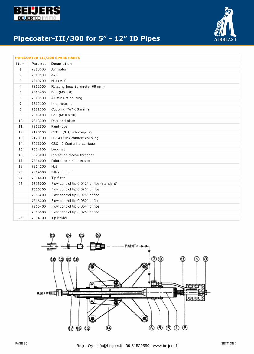
AIRBLAST
PAGE 80
PIPECOATER-III/300 SPARE PARTS
Item Part no. Description
1 7310000 Air motor
2 7310100 Axle
3 7310200 Nut (M10)
4 7312000 Rotating head (diameter 69 mm)
5 7310400 Bolt (M6 x 8)
6 7310500 Aluminium housing
7 7312100 Inlet housing
8 7312200 Coupling (¼” x 8 mm )
9 7315600 Bolt (M10 x 10)
10 7313700 Rear end plate
11 7312500 Paint tube
12 2176100 CCC-38/F Quick coupling
13 2178100 IF-14 Quick connect coupling
14 3011000 CBC - 2 Centering carriage
15 7314800 Lock nut
16 3025000 Protection sleeve threaded
17 7314000 Paint tube stainless steel
18 7314100 Nut
23 7314500 Filter holder
24 7314600 Tip filter
25 7315000 Flow control tip 0,042” orifice (standard)
7315100 Flow control tip 0,020” orifice
7315200 Flow control tip 0,028” orifice
7315300 Flow control tip 0,060” orifice
7315400 Flow control tip 0,064” orifice
7315500 Flow control tip 0,076” orifice
26 7314700 Tip holder
Pipecoater-III/300 for 5” - 12” ID Pipes
SECTION 3Beijer Oy - [email protected] - 09-61520550 - www.beijers.fi

AIRBLAST
PAGE 81
PIPECOATER-III/900 is designed to coat the inside of pipe or tubing ranging from 300 to 900 mm (12” - 36”) ID without the need to rotate pipe or tubing and to apply an even paint film thickness throughout. Generally, any type of coating may be used in this tool that can be airless sprayed.
PIPECOATER-III/900 tool can be connected to a suitable airless paint spray machine of minimum 45:1 ratio. The unit is connected to the end of a pipe lance and connected to the high pressure paint hose coming from the spray pump. An air hose is required to connect to the PIPECOATER-III/900. Once the PIPECOATER-III/900 is positioned within the pipe or tubing regulate the paint and air flow to the correct pressure. The spray gun is triggered to begin the paint flow. The paint will be sprayed through a spin nozzle controlled by the air flow in a 360° spraying pattern.
To stop the PIPECOATER-III/900, release the spray gun trigger and shut off the air supply to the unit. For the best possible result, one man should operate the spray gun while another man pulls the tool through the pipe or tubing.
Advantages• Efficiently handles wide range of coatings• Applies uniform layer at remarkable speed• No need to rotate the pipe or tubing
ORDERING INFORMATIONPIPECOATER-III/900 INTERNAL PIPECOATER ASSEMBLY
PIPECOATER-III range are economy models, developed for pipe or tubing ranging from 76 mm to 900 mm(3” - 36”) ID. The three models are executed with different centering devices which must be set to the rightdiameter manually.
7303000 PIPECOATER-III/900 complete unit with centering carriage. For pipes with ID of 300 mm to 900 mm (12” - 36”)
Pipecoater-III/900 for 12” - 36” ID Pipes
3
SECTION 3 Beijer Oy - [email protected] - 09-61520550 - www.beijers.fi
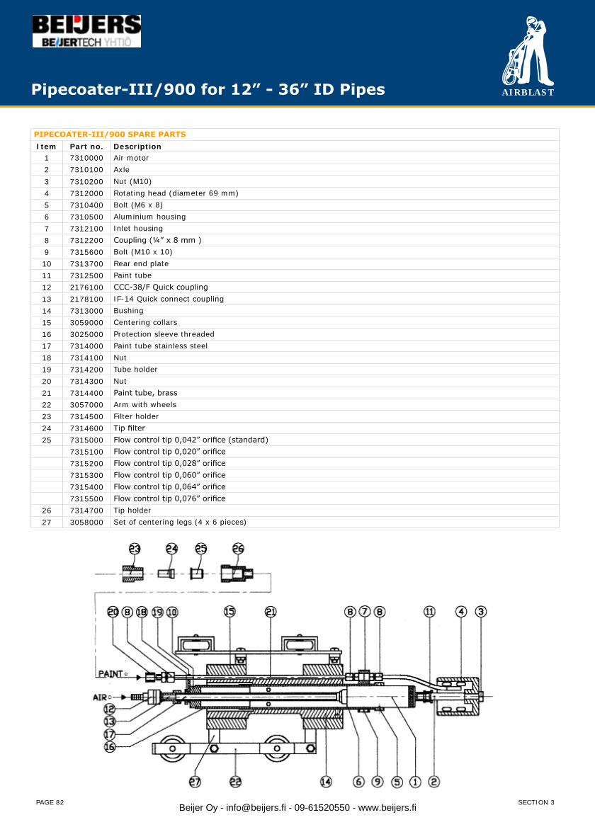
AIRBLAST
PAGE 82
PIPECOATER-III/900 SPARE PARTSItem Part no. Description
1 7310000 Air motor2 7310100 Axle3 7310200 Nut (M10)4 7312000 Rotating head (diameter 69 mm)5 7310400 Bolt (M6 x 8)6 7310500 Aluminium housing7 7312100 Inlet housing8 7312200 Coupling (¼” x 8 mm )9 7315600 Bolt (M10 x 10)10 7313700 Rear end plate11 7312500 Paint tube12 2176100 CCC-38/F Quick coupling13 2178100 IF-14 Quick connect coupling14 7313000 Bushing15 3059000 Centering collars16 3025000 Protection sleeve threaded17 7314000 Paint tube stainless steel18 7314100 Nut19 7314200 Tube holder20 7314300 Nut21 7314400 Paint tube, brass22 3057000 Arm with wheels23 7314500 Filter holder24 7314600 Tip filter25 7315000 Flow control tip 0,042” orifice (standard)
7315100 Flow control tip 0,020” orifice7315200 Flow control tip 0,028” orifice7315300 Flow control tip 0,060” orifice7315400 Flow control tip 0,064” orifice7315500 Flow control tip 0,076” orifice
26 7314700 Tip holder27 3058000 Set of centering legs (4 x 6 pieces)
Pipecoater-III/900 for 12” - 36” ID Pipes
SECTION 3Beijer Oy - [email protected] - 09-61520550 - www.beijers.fi

AIRBLAST
PAGE 83
PIPECOATER-IV tool is designed to coat the inside of pipe or tubing ranging from 25 to 300 mm (1” - 12”) ID without the need to rotate pipe or tubing and to apply an even paint film thickness throughout. Generally, any type of coating may be used in this tool that can be airless sprayed.
PIPECOATER-IV tool can be connected to a suitable airless paint spray machine of minimum 45:1 ratio. The unit is connected to the end of a pipe lance and connected to the high pressure paint hose coming from the spray pump. An air hose is required to connect to the PIPECOATER-IV. Once the PIPECOATER-IV is positioned within the pipe or tubing regulate the paint and air flow to the correct pressure. The spray gun is triggered to begin the paint flow. The paint will be sprayed through the round spray nozzle controlled by the air flow in a 360° spraying pattern.
To stop the PIPECOATER-IV, release the spray gun trigger and shut off the air supply to the unit. For the best possible result, one man should operate the spray gun while another man pulls the tool through the pipe or tubing.
Advantages• Efficiently handles wide range of coatings• Applies uniform layer at remarkable speed• No need to rotate the pipe or tubing
Pipecoater-IV for 1” - 12” ID Pipes
ORDERING INFORMATION
PIPECOATER-IV INTERNAL PIPECOATER ASSEMBLY
7304001 PIPECOATER-IV – bare – including TNSSTC 6 tip (1.07mm) assy and AB-SS 100 filter (parts 1 – 4, 6 - 10 + 12).Optional with centering collars for pipes with ID: 76 – 125mm (3” to 5”) and with 125 – 300mm (5” to 12”).
3
SECTION 3 Beijer Oy - [email protected] - 09-61520550 - www.beijers.fi
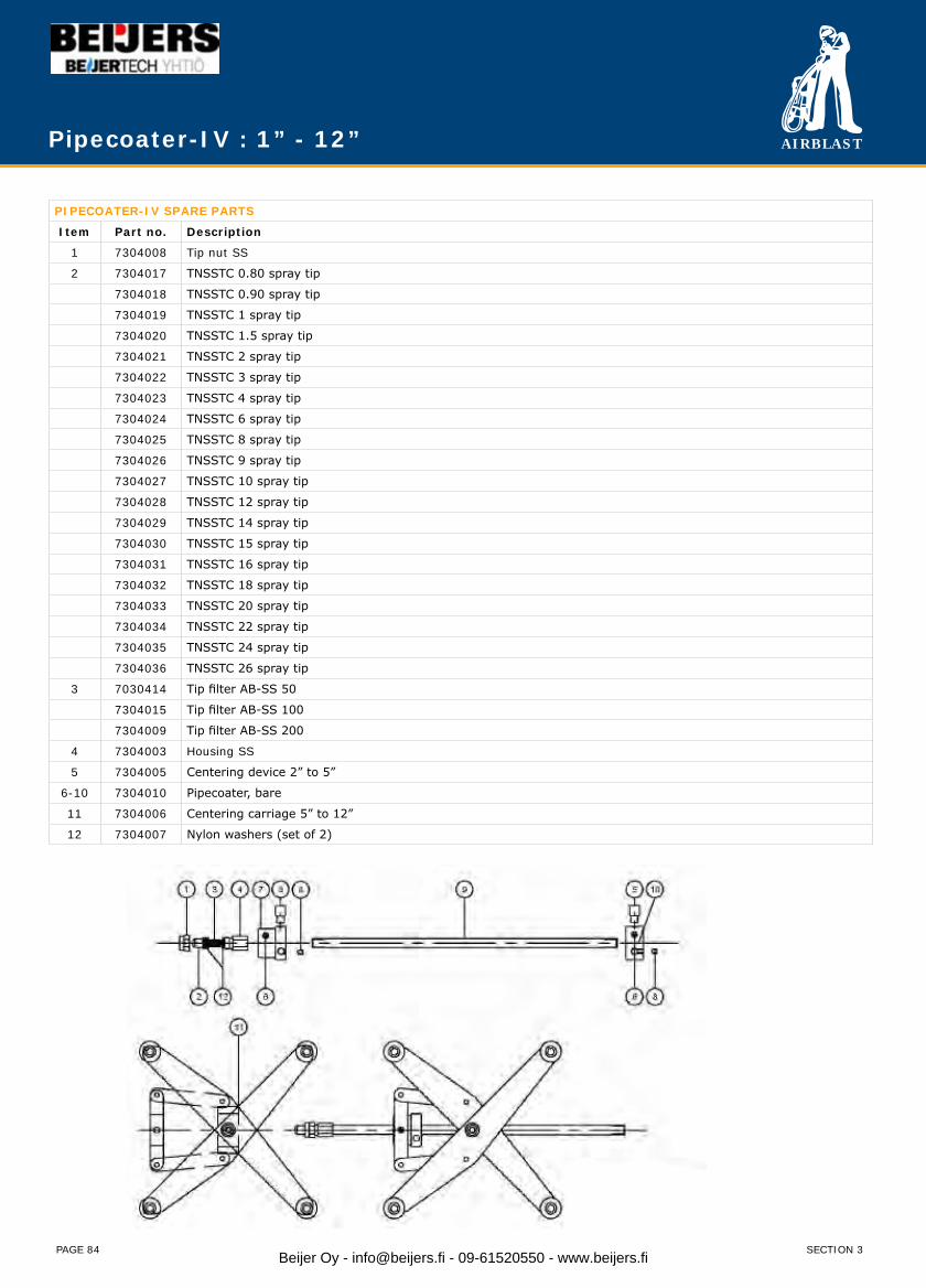
AIRBLAST
PAGE 84
Pipecoater-IV : 1” - 12”
PIPECOATER-IV SPARE PARTS
Item Part no. Description
1 7304008 Tip nut SS
2 7304017 TNSSTC 0.80 spray tip
7304018 TNSSTC 0.90 spray tip
7304019 TNSSTC 1 spray tip
7304020 TNSSTC 1.5 spray tip
7304021 TNSSTC 2 spray tip
7304022 TNSSTC 3 spray tip
7304023 TNSSTC 4 spray tip
7304024 TNSSTC 6 spray tip
7304025 TNSSTC 8 spray tip
7304026 TNSSTC 9 spray tip
7304027 TNSSTC 10 spray tip
7304028 TNSSTC 12 spray tip
7304029 TNSSTC 14 spray tip
7304030 TNSSTC 15 spray tip
7304031 TNSSTC 16 spray tip
7304032 TNSSTC 18 spray tip
7304033 TNSSTC 20 spray tip
7304034 TNSSTC 22 spray tip
7304035 TNSSTC 24 spray tip
7304036 TNSSTC 26 spray tip
3 7030414 Tip filter AB-SS 50
7304015 Tip filter AB-SS 100
7304009 Tip filter AB-SS 200
4 7304003 Housing SS
5 7304005 Centering device 2” to 5”
6-10 7304010 Pipecoater, bare
11 7304006 Centering carriage 5” to 12”
12 7304007 Nylon washers (set of 2)
SECTION 3Beijer Oy - [email protected] - 09-61520550 - www.beijers.fi
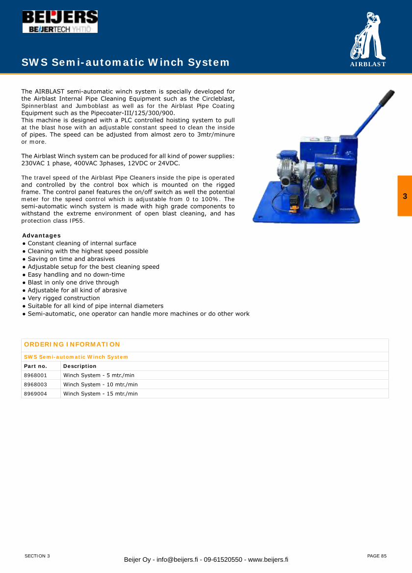
AIRBLAST
PAGE 85
The AIRBLAST semi-automatic winch system is specially developed for the Airblast Internal Pipe Cleaning Equipment such as the Circleblast, Spinnerblast and Jumboblast as well as for the Airblast Pipe Coating Equipment such as the Pipecoater-III/125/300/900.This machine is designed with a PLC controlled hoisting system to pull at the blast hose with an adjustable constant speed to clean the inside of pipes. The speed can be adjusted from almost zero to 3mtr/minure or more.
The Airblast Winch system can be produced for all kind of power supplies: 230VAC 1 phase, 400VAC 3phases, 12VDC or 24VDC.
The travel speed of the Airblast Pipe Cleaners inside the pipe is operated and controlled by the control box which is mounted on the rigged frame. The control panel features the on/off switch as well the potential meter for the speed control which is adjustable from 0 to 100%. The semi-automatic winch system is made with high grade components to withstand the extreme environment of open blast cleaning, and has protection class IP55.
ORDERING INFORMATION
SWS Semi-automatic Winch System
Part no. Description
8968001 Winch System - 5 mtr./min
8968003 Winch System - 10 mtr./min
8969004 Winch System - 15 mtr./min
SWS Semi-automatic Winch System
Advantages● Constant cleaning of internal surface● Cleaning with the highest speed possible● Saving on time and abrasives● Adjustable setup for the best cleaning speed● Easy handling and no down-time● Blast in only one drive through● Adjustable for all kind of abrasive● Very rigged construction● Suitable for all kind of pipe internal diameters● Semi-automatic, one operator can handle more machines or do other work
3
SECTION 3 Beijer Oy - [email protected] - 09-61520550 - www.beijers.fi
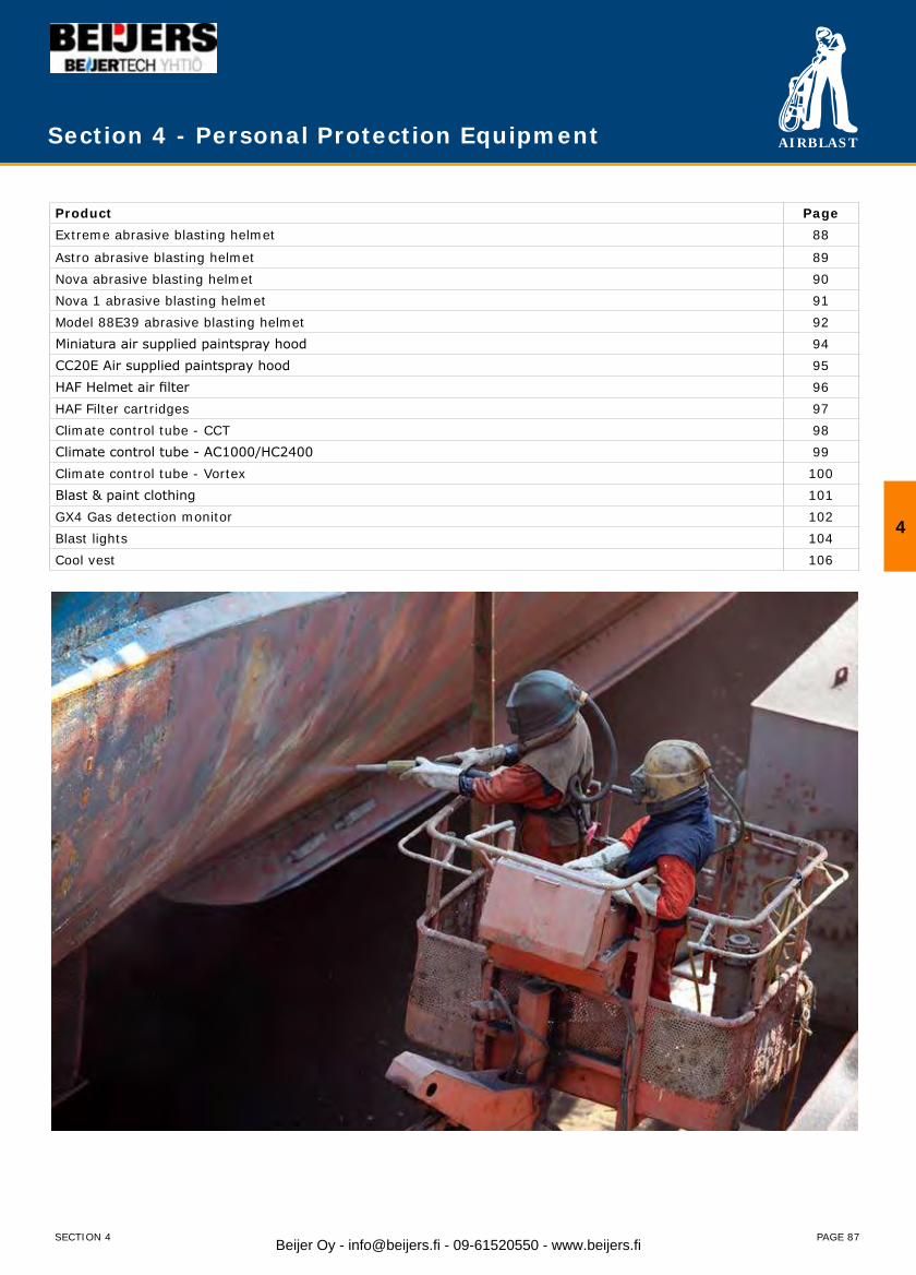
AIRBLAST
PAGE 87
Section 4 - Personal Protection Equipment
Product PageExtreme abrasive blasting helmet 88
Astro abrasive blasting helmet 89Nova abrasive blasting helmet 90Nova 1 abrasive blasting helmet 91Model 88E39 abrasive blasting helmet 92Miniatura air supplied paintspray hood 94CC20E Air supplied paintspray hood 95HAF Helmet air filter 96HAF Filter cartridges 97Climate control tube - CCT 98Climate control tube - AC1000/HC2400 99Climate control tube - Vortex 100Blast & paint clothing 101GX4 Gas detection monitor 102Blast lights 104Cool vest 106
4
SECTION 4 Beijer Oy - [email protected] - 09-61520550 - www.beijers.fi
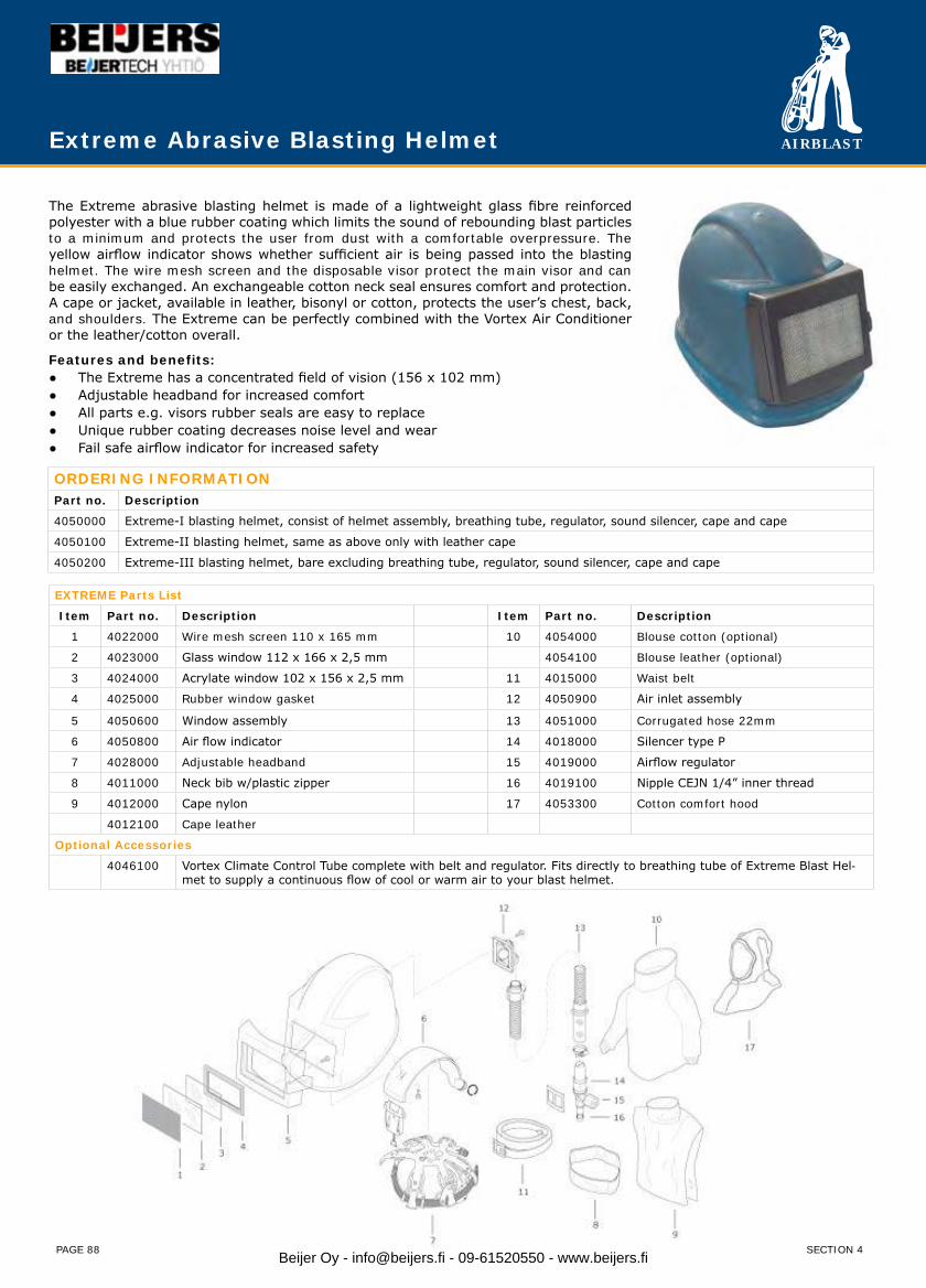
AIRBLAST
PAGE 88
Extreme Abrasive Blasting Helmet
The Extreme abrasive blasting helmet is made of a lightweight glass fibre reinforced polyester with a blue rubber coating which limits the sound of rebounding blast particles to a minimum and protects the user from dust with a comfortable overpressure. The yellow airflow indicator shows whether sufficient air is being passed into the blasting helmet. The wire mesh screen and the disposable visor protect the main visor and can be easily exchanged. An exchangeable cotton neck seal ensures comfort and protection. A cape or jacket, available in leather, bisonyl or cotton, protects the user’s chest, back, and shoulders. The Extreme can be perfectly combined with the Vortex Air Conditioner or the leather/cotton overall.
Features and benefits:● The Extreme has a concentrated field of vision (156 x 102 mm)● Adjustable headband for increased comfort● All parts e.g. visors rubber seals are easy to replace● Unique rubber coating decreases noise level and wear● Fail safe airflow indicator for increased safety
ORDERING INFORMATIONPart no. Description
4050000 Extreme-I blasting helmet, consist of helmet assembly, breathing tube, regulator, sound silencer, cape and cape
4050100 Extreme-II blasting helmet, same as above only with leather cape
4050200 Extreme-III blasting helmet, bare excluding breathing tube, regulator, sound silencer, cape and cape
EXTREME Parts List
Item Part no. Description Item Part no. Description
1 4022000 Wire mesh screen 110 x 165 mm 10 4054000 Blouse cotton (optional)
2 4023000 Glass window 112 x 166 x 2,5 mm 4054100 Blouse leather (optional)
3 4024000 Acrylate window 102 x 156 x 2,5 mm 11 4015000 Waist belt
4 4025000 Rubber window gasket 12 4050900 Air inlet assembly
5 4050600 Window assembly 13 4051000 Corrugated hose 22mm
6 4050800 Air flow indicator 14 4018000 Silencer type P
7 4028000 Adjustable headband 15 4019000 Airflow regulator
8 4011000 Neck bib w/plastic zipper 16 4019100 Nipple CEJN 1/4” inner thread
9 4012000 Cape nylon 17 4053300 Cotton comfort hood
4012100 Cape leather
Optional Accessories
4046100 Vortex Climate Control Tube complete with belt and regulator. Fits directly to breathing tube of Extreme Blast Hel-met to supply a continuous flow of cool or warm air to your blast helmet.
SECTION 4Beijer Oy - [email protected] - 09-61520550 - www.beijers.fi
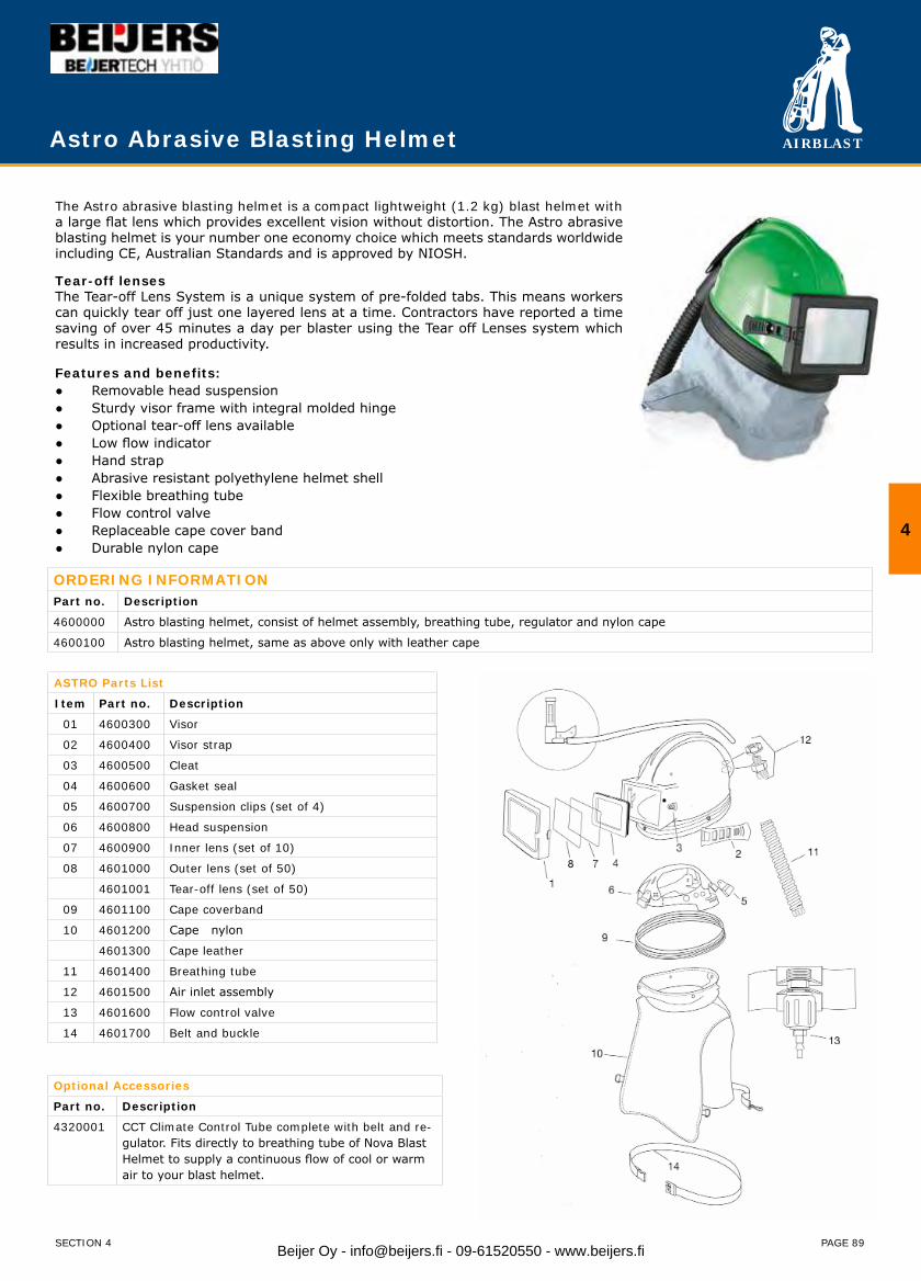
AIRBLAST
PAGE 89
Astro Abrasive Blasting Helmet
The Astro abrasive blasting helmet is a compact lightweight (1.2 kg) blast helmet with a large flat lens which provides excellent vision without distortion. The Astro abrasive blasting helmet is your number one economy choice which meets standards worldwide including CE, Australian Standards and is approved by NIOSH.
Tear-off lenses The Tear-off Lens System is a unique system of pre-folded tabs. This means workers can quickly tear off just one layered lens at a time. Contractors have reported a time saving of over 45 minutes a day per blaster using the Tear off Lenses system which results in increased productivity.
Features and benefits:● Removable head suspension● Sturdy visor frame with integral molded hinge● Optional tear-off lens available● Low flow indicator● Hand strap● Abrasive resistant polyethylene helmet shell● Flexible breathing tube● Flow control valve● Replaceable cape cover band● Durable nylon cape
ORDERING INFORMATIONPart no. Description
4600000 Astro blasting helmet, consist of helmet assembly, breathing tube, regulator and nylon cape
4600100 Astro blasting helmet, same as above only with leather cape
ASTRO Parts List
Item Part no. Description
01 4600300 Visor
02 4600400 Visor strap
03 4600500 Cleat
04 4600600 Gasket seal
05 4600700 Suspension clips (set of 4)
06 4600800 Head suspension
07 4600900 Inner lens (set of 10)
08 4601000 Outer lens (set of 50)
4601001 Tear-off lens (set of 50)
09 4601100 Cape coverband
10 4601200 Cape nylon
4601300 Cape leather
11 4601400 Breathing tube
12 4601500 Air inlet assembly
13 4601600 Flow control valve
14 4601700 Belt and buckle
Optional Accessories
Part no. Description
4320001 CCT Climate Control Tube complete with belt and re-gulator. Fits directly to breathing tube of Nova Blast Helmet to supply a continuous flow of cool or warm air to your blast helmet.
4
SECTION 4 Beijer Oy - [email protected] - 09-61520550 - www.beijers.fi
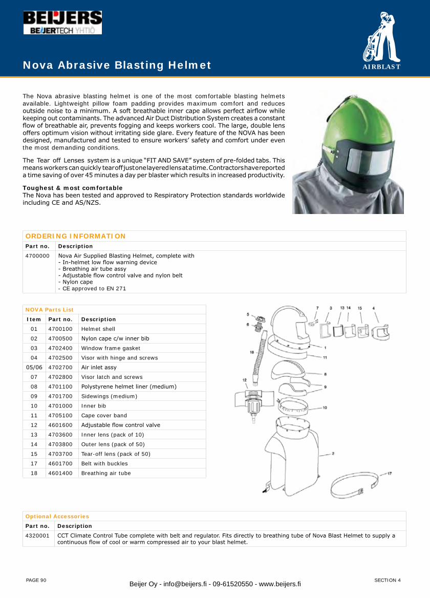
AIRBLAST
PAGE 90
Nova Abrasive Blasting Helmet
The Nova abrasive blasting helmet is one of the most comfortable blasting helmets available. Lightweight pillow foam padding provides maximum comfort and reduces outside noise to a minimum. A soft breathable inner cape allows perfect airflow while keeping out contaminants. The advanced Air Duct Distribution System creates a constant flow of breathable air, prevents fogging and keeps workers cool. The large, double lens offers optimum vision without irritating side glare. Every feature of the NOVA has been designed, manufactured and tested to ensure workers’ safety and comfort under even the most demanding conditions.
The Tear off Lenses system is a unique “FIT AND SAVE” system of pre-folded tabs. This means workers can quickly tear off just one layered lens at a time. Contractors have reported a time saving of over 45 minutes a day per blaster which results in increased productivity.
Toughest & most comfortableThe Nova has been tested and approved to Respiratory Protection standards worldwide including CE and AS/NZS.
ORDERING INFORMATIONPart no. Description
4700000 Nova Air Supplied Blasting Helmet, complete with- In-helmet low flow warning device- Breathing air tube assy - Adjustable flow control valve and nylon belt - Nylon cape - CE approved to EN 271
NOVA Parts List
Item Part no. Description
01 4700100 Helmet shell
02 4700500 Nylon cape c/w inner bib
03 4702400 Window frame gasket
04 4702500 Visor with hinge and screws
05/06 4702700 Air inlet assy
07 4702800 Visor latch and screws
08 4701100 Polystyrene helmet liner (medium)
09 4701700 Sidewings (medium)
10 4701000 Inner bib
11 4705100 Cape cover band
12 4601600 Adjustable flow control valve
13 4703600 Inner lens (pack of 10)
14 4703800 Outer lens (pack of 50)
15 4703700 Tear-off lens (pack of 50)
17 4601700 Belt with buckles
18 4601400 Breathing air tube
Optional Accessories
Part no. Description
4320001 CCT Climate Control Tube complete with belt and regulator. Fits directly to breathing tube of Nova Blast Helmet to supply a continuous flow of cool or warm compressed air to your blast helmet.
SECTION 4Beijer Oy - [email protected] - 09-61520550 - www.beijers.fi
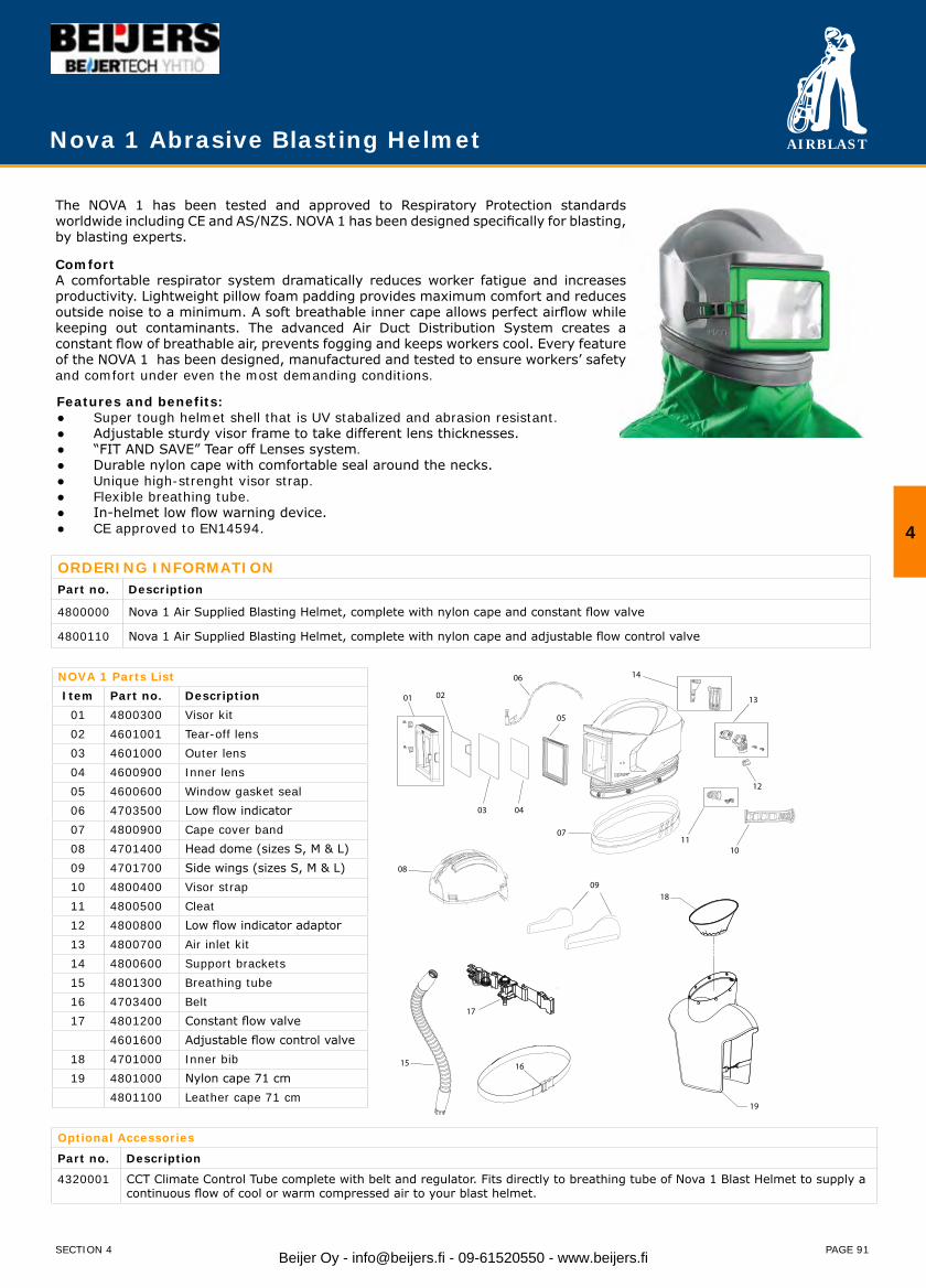
AIRBLAST
PAGE 91
Nova 1 Abrasive Blasting Helmet
The NOVA 1 has been tested and approved to Respiratory Protection standards worldwide including CE and AS/NZS. NOVA 1 has been designed specifically for blasting, by blasting experts.
ComfortA comfortable respirator system dramatically reduces worker fatigue and increases productivity. Lightweight pillow foam padding provides maximum comfort and reduces outside noise to a minimum. A soft breathable inner cape allows perfect airflow while keeping out contaminants. The advanced Air Duct Distribution System creates a constant flow of breathable air, prevents fogging and keeps workers cool. Every feature of the NOVA 1 has been designed, manufactured and tested to ensure workers’ safety and comfort under even the most demanding conditions.
Features and benefits:● Super tough helmet shell that is UV stabalized and abrasion resistant.● Adjustable sturdy visor frame to take different lens thicknesses.● “FIT AND SAVE” Tear off Lenses system.● Durable nylon cape with comfortable seal around the necks.● Unique high-strenght visor strap.● Flexible breathing tube.● In-helmet low flow warning device.● CE approved to EN14594.
ORDERING INFORMATIONPart no. Description
4800000 Nova 1 Air Supplied Blasting Helmet, complete with nylon cape and constant flow valve
4800110 Nova 1 Air Supplied Blasting Helmet, complete with nylon cape and adjustable flow control valve
NOVA 1 Parts ListItem Part no. Description
01 4800300 Visor kit02 4601001 Tear-off lens03 4601000 Outer lens04 4600900 Inner lens05 4600600 Window gasket seal06 4703500 Low flow indicator07 4800900 Cape cover band08 4701400 Head dome (sizes S, M & L)09 4701700 Side wings (sizes S, M & L)10 4800400 Visor strap11 4800500 Cleat12 4800800 Low flow indicator adaptor13 4800700 Air inlet kit14 4800600 Support brackets15 4801300 Breathing tube16 4703400 Belt17 4801200 Constant flow valve
4601600 Adjustable flow control valve18 4701000 Inner bib19 4801000 Nylon cape 71 cm
4801100 Leather cape 71 cm
4
SECTION 4
Optional Accessories
Part no. Description
4320001 CCT Climate Control Tube complete with belt and regulator. Fits directly to breathing tube of Nova 1 Blast Helmet to supply a continuous flow of cool or warm compressed air to your blast helmet.
03
1110
130201
04
06 14
07
12
05
08
09
15 16
17
18
19
Beijer Oy - [email protected] - 09-61520550 - www.beijers.fi
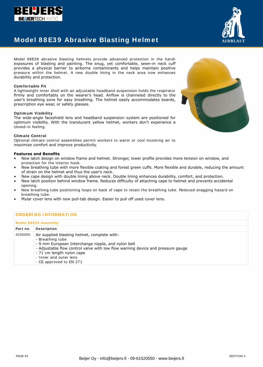
AIRBLAST
PAGE 92
Model 88E39 abrasive blasting helmets provide advanced protection in the harsh exposures of blasting and painting. The snug, yet comfortable, sewn-in neck cuff provides a physical barrier to airborne contaminants and helps maintain positive pressure within the helmet. A new double lining in the neck area now enhances durability and protection.
Comfortable FitA lightweight inner shell with an adjustable headband suspension holds the respirator firmly and comfortably on the wearer’s head. Airflow is channeled directly to the user’s breathing zone for easy breathing. The helmet easily accommodates beards, prescription eye wear, or safety glasses.
Optimum VisibilityThe wide-angle faceshield lens and headband suspension system are positioned for optimum visibility. With the translucent yellow helmet, workers don’t experience a closed-in feeling.
Climate ControlOptional climate control assemblies permit workers to warm or cool incoming air to maximize comfort and improve productivity.
Features and BenefitsNew latch design on window frame and helmet. Stronger, lower profile provides more tension on window, and • protection for the interior hook.New breathing tube with more flexible coating and forest green cuffs. More flexible and durable, reducing the amount • of strain on the helmet and thus the user’s neck.New cape design with double lining above neck. Double lining enhances durability, comfort, and protection.• New latch position behind window frame. Reduces difficulty of attaching cape to helmet and prevents accidental • opening.New breathing tube positioning loops on back of cape to retain the breathing tube. Reduced snagging hazard on • breathing tube. Mylar cover lens with new pull-tab design. Easier to pull off used cover lens.•
ORDERING INFORMATION
Model 88E39 Assembly
Part no. Description
4200000 Air supplied blasting helmet, complete with: - Breathing tube - 9 mm European Interchange nipple, and nylon belt - Adjustable flow control valve with low flow warning device and pressure gauge - 71 cm length nylon cape - Inner and outer lens - CE approved to EN 271
Model 88E39 Abrasive Blasting Helmet
SECTION 4Beijer Oy - [email protected] - 09-61520550 - www.beijers.fi
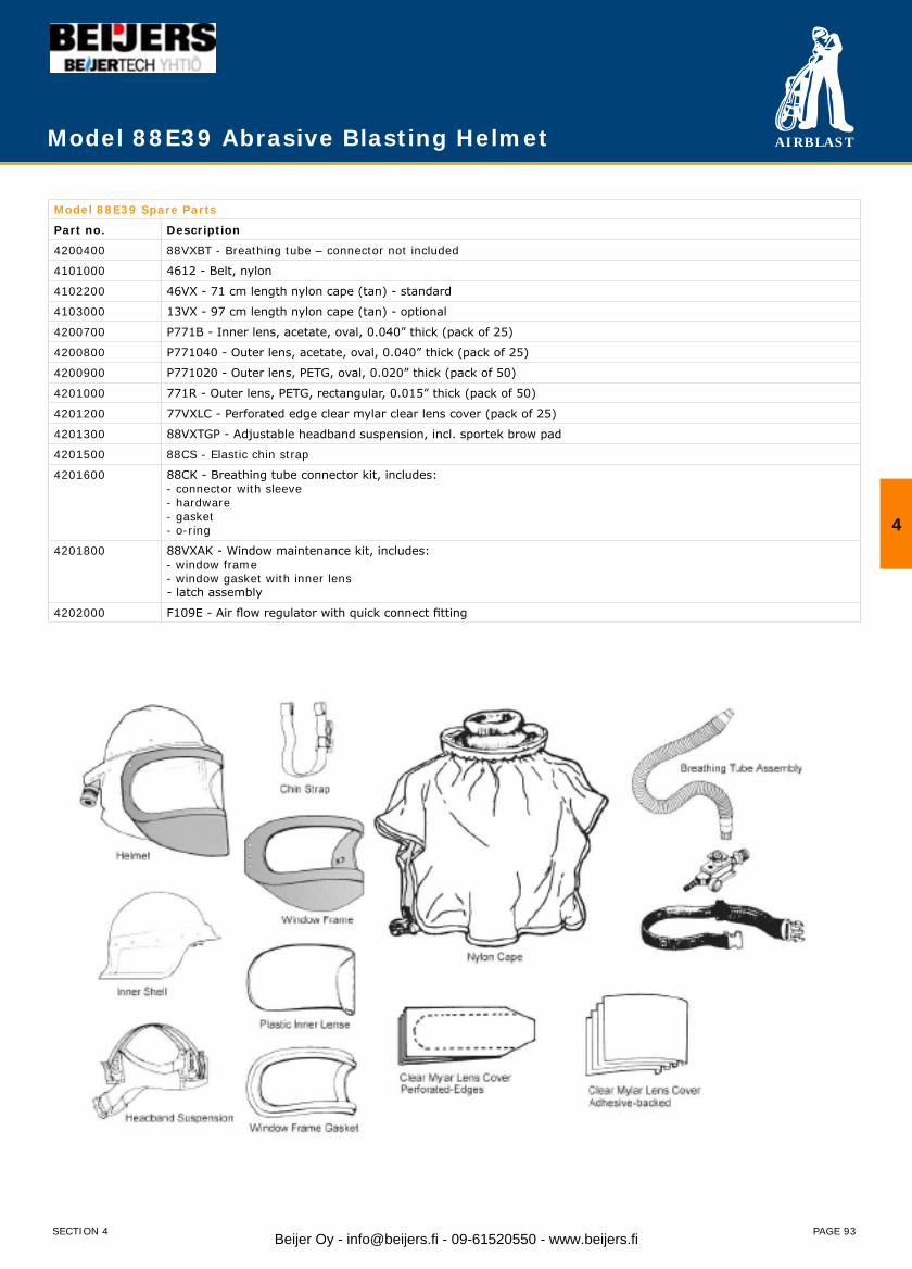
AIRBLAST
PAGE 93
Model 88E39 Spare Parts
Part no. Description
4200400 88VXBT - Breathing tube – connector not included
4101000 4612 - Belt, nylon
4102200 46VX - 71 cm length nylon cape (tan) - standard
4103000 13VX - 97 cm length nylon cape (tan) - optional
4200700 P771B - Inner lens, acetate, oval, 0.040” thick (pack of 25)
4200800 P771040 - Outer lens, acetate, oval, 0.040” thick (pack of 25)
4200900 P771020 - Outer lens, PETG, oval, 0.020” thick (pack of 50)
4201000 771R - Outer lens, PETG, rectangular, 0.015” thick (pack of 50)
4201200 77VXLC - Perforated edge clear mylar clear lens cover (pack of 25)
4201300 88VXTGP - Adjustable headband suspension, incl. sportek brow pad
4201500 88CS - Elastic chin strap
4201600 88CK - Breathing tube connector kit, includes: - connector with sleeve - hardware - gasket - o-ring
4201800 88VXAK - Window maintenance kit, includes: - window frame - window gasket with inner lens - latch assembly
4202000 F109E - Air flow regulator with quick connect fitting
Model 88E39 Abrasive Blasting Helmet
SECTION 4
4
Beijer Oy - [email protected] - 09-61520550 - www.beijers.fi
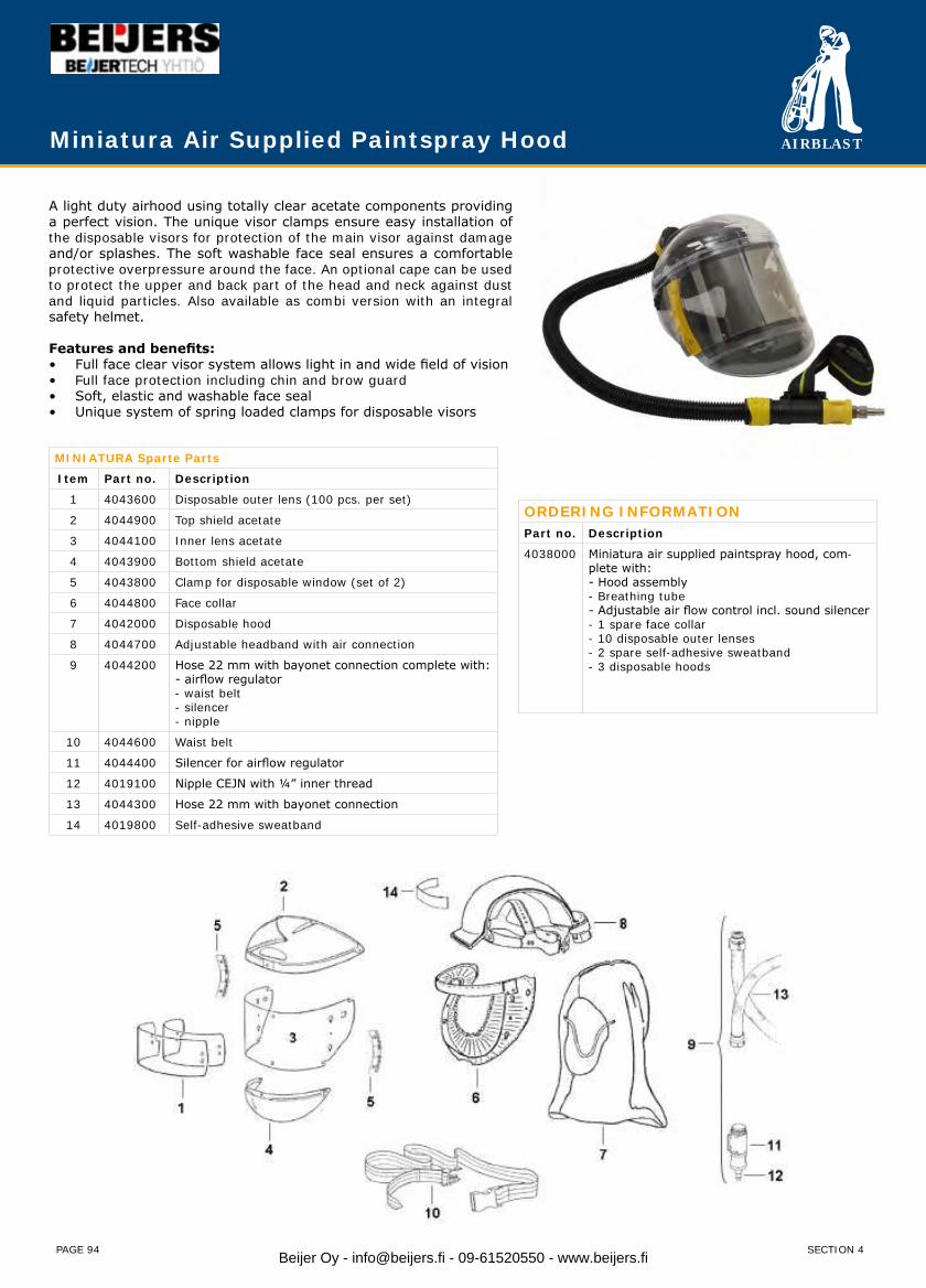
AIRBLAST
PAGE 94
A light duty airhood using totally clear acetate components providing a perfect vision. The unique visor clamps ensure easy installation of the disposable visors for protection of the main visor against damage and/or splashes. The soft washable face seal ensures a comfortable protective overpressure around the face. An optional cape can be used to protect the upper and back part of the head and neck against dust and liquid particles. Also available as combi version with an integral safety helmet.
Features and benefits:Full face clear visor system allows light in and wide field of vision• Full face protection including chin and brow guard• Soft, elastic and washable face seal• Unique system of spring loaded clamps for disposable visors•
ORDERING INFORMATIONPart no. Description
4038000 Miniatura air supplied paintspray hood, com-plete with:- Hood assembly- Breathing tube- Adjustable air flow control incl. sound silencer- 1 spare face collar- 10 disposable outer lenses- 2 spare self-adhesive sweatband- 3 disposable hoods
MINIATURA Sparte Parts
Item Part no. Description
1 4043600 Disposable outer lens (100 pcs. per set)
2 4044900 Top shield acetate
3 4044100 Inner lens acetate
4 4043900 Bottom shield acetate
5 4043800 Clamp for disposable window (set of 2)
6 4044800 Face collar
7 4042000 Disposable hood
8 4044700 Adjustable headband with air connection
9 4044200 Hose 22 mm with bayonet connection complete with:- airflow regulator - waist belt- silencer - nipple
10 4044600 Waist belt
11 4044400 Silencer for airflow regulator
12 4019100 Nipple CEJN with ¼” inner thread
13 4044300 Hose 22 mm with bayonet connection
14 4019800 Self-adhesive sweatband
Miniatura Air Supplied Paintspray Hood
SECTION 4Beijer Oy - [email protected] - 09-61520550 - www.beijers.fi
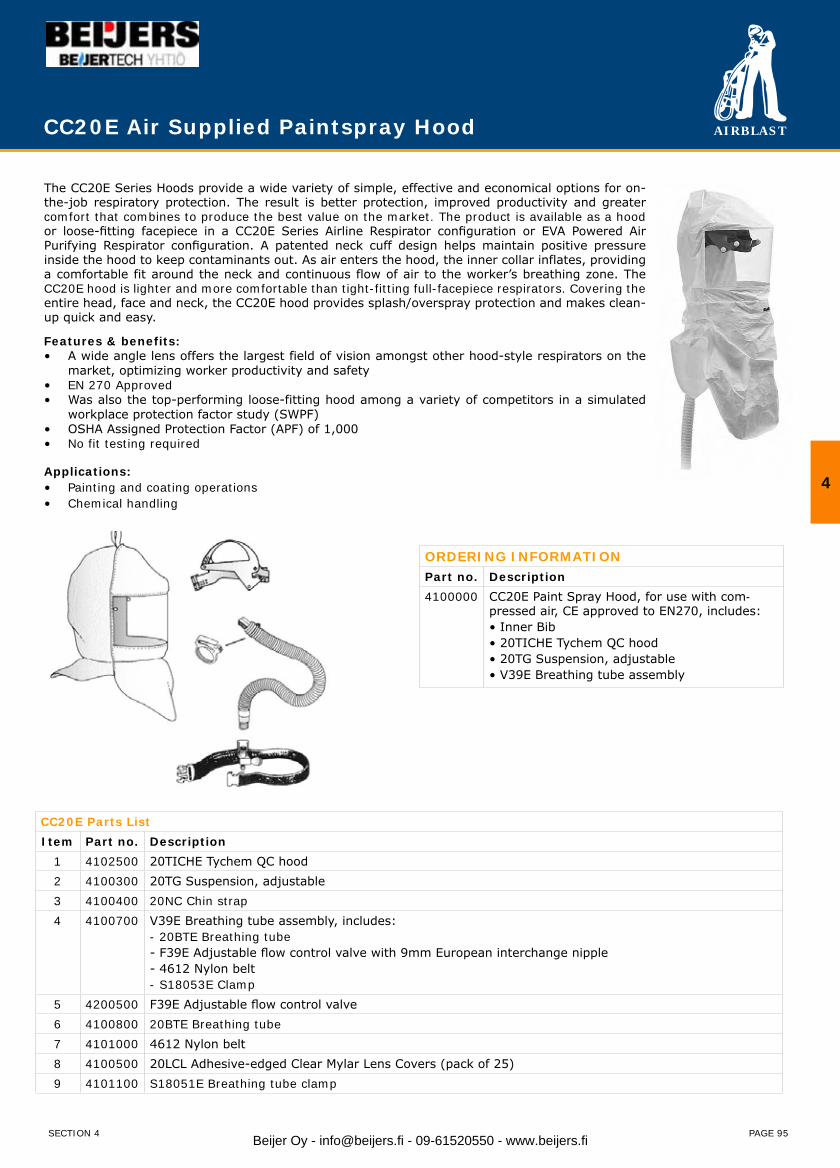
AIRBLAST
PAGE 95
The CC20E Series Hoods provide a wide variety of simple, effective and economical options for on-the-job respiratory protection. The result is better protection, improved productivity and greater comfort that combines to produce the best value on the market. The product is available as a hood or loose-fitting facepiece in a CC20E Series Airline Respirator configuration or EVA Powered Air Purifying Respirator configuration. A patented neck cuff design helps maintain positive pressure inside the hood to keep contaminants out. As air enters the hood, the inner collar inflates, providing a comfortable fit around the neck and continuous flow of air to the worker’s breathing zone. The CC20E hood is lighter and more comfortable than tight-fitting full-facepiece respirators. Covering the entire head, face and neck, the CC20E hood provides splash/overspray protection and makes clean-up quick and easy.
Features & benefits:A wide angle lens offers the largest field of vision amongst other hood-style respirators on the • market, optimizing worker productivity and safetyEN 270 Approved• Was also the top-performing loose-fitting hood among a variety of competitors in a simulated • workplace protection factor study (SWPF)OSHA Assigned Protection Factor (APF) of 1,000 • No fit testing required•
Applications:Painting and coating operations• Chemical handling•
ORDERING INFORMATIONPart no. Description4100000 CC20E Paint Spray Hood, for use with com-
pressed air, CE approved to EN270, includes:• Inner Bib• 20TICHE Tychem QC hood• 20TG Suspension, adjustable• V39E Breathing tube assembly
CC20E Parts ListItem Part no. Description
1 4102500 20TICHE Tychem QC hood2 4100300 20TG Suspension, adjustable3 4100400 20NC Chin strap4 4100700 V39E Breathing tube assembly, includes:
- 20BTE Breathing tube - F39E Adjustable flow control valve with 9mm European interchange nipple - 4612 Nylon belt - S18053E Clamp
5 4200500 F39E Adjustable flow control valve6 4100800 20BTE Breathing tube7 4101000 4612 Nylon belt8 4100500 20LCL Adhesive-edged Clear Mylar Lens Covers (pack of 25)9 4101100 S18051E Breathing tube clamp
CC20E Air Supplied Paintspray Hood
SECTION 4
4
Beijer Oy - [email protected] - 09-61520550 - www.beijers.fi

AIRBLAST
PAGE 96
Airblast Helmet Air Filter (HAF) is designed to remove oil mist, water vapour and particulates down to 0.5 microns from breathing grade compressed air. The Airblast Helmet Air Filter meets OSHA regulation 1910.94 (6) (ii), requiring a trap and carbon filter be installed and regularly maintained to remove objectionable odours, as well as water, oil mist and other particulates. The Airblast HAF is supplied incl. pressure reducing valve to reduce the pressure to the requirements of supplied air respirators, providing that the inlet pressure does not exceed 8,6 bar (125 PSI).
AdvantagesOne filter suitable for multiple respirators, up to 6 users• Polypropylene filter cartridge casing eliminates corrosion hazard• Filter cartridge lasts up to 3 months (based on 40 hours week)• Filters can be floor or wall mounted•
Helmet Air Filter for 1 - 6 users
ORDERING INFORMATIONPart no. Description
4300000 HAF-I Helmet Air Filter for 1-2 users
4320000 HAF-II Helmet Air Filter for 1-6 users
HAF Parts List
Item Part no. Description
01 4301000 3/8” Tee - brass
02 4302000 3/8” Pressure regulator
03 4303000 Pressure gauge
04 4304000 3/8” Pressure regulator – high flow (optional)
05 4305000 Pressure gauge – high flow (optional)
06 4306000 Pressure relief valve
07 4307000 Filter cover for 1 or 2 users HAF
08 4308000 Filter cover for 1-6 users HAF (optional)
09 4309000 Outlet manifold for 1-6 users (optional)
10 4310000 Filter housing
11 4311000 O-ring (set of 2)
12 4312000 Bolt (set of 4)
13 4313000 Base / Wall mount
14 2175200 CCC-38/I Quick coupling 1 or 2 users
15 2174200 CCC-38/O Quick coupling for 1-6 users
16 2225500 Hex nipple 1”
17 4250401 Filter cartridge for HAF
18 2170400 KAG-10 Quick coupling 1”outer thread
19 4316000 Drain valve - brass
Delivery includes
HAF Assembly, pressure regulator, pressure relief valve, bracket for stand or wall mount, drain valve and filter cartridge.
Helmet Air Hose - Optional
Part no. Description
2527000 Helmet Air Hose 3/8” - 9 mm ID (9 x 16), 10 bar working pressure
2527400 Helmet Air Hose 3/8” - 9 mm ID (9 x 16), 10 bar working pressure, coupled 5 meters
2527500 Helmet Air Hose 3/8” - 9 mm ID (9 x 16), 10 bar working pressure, coupled 20 meters
2527700 Helmet Air Hose 3/8” - 9 mm ID (9 x 16), 10 bar working pressure, coupled 40 meters
SECTION 4Beijer Oy - [email protected] - 09-61520550 - www.beijers.fi
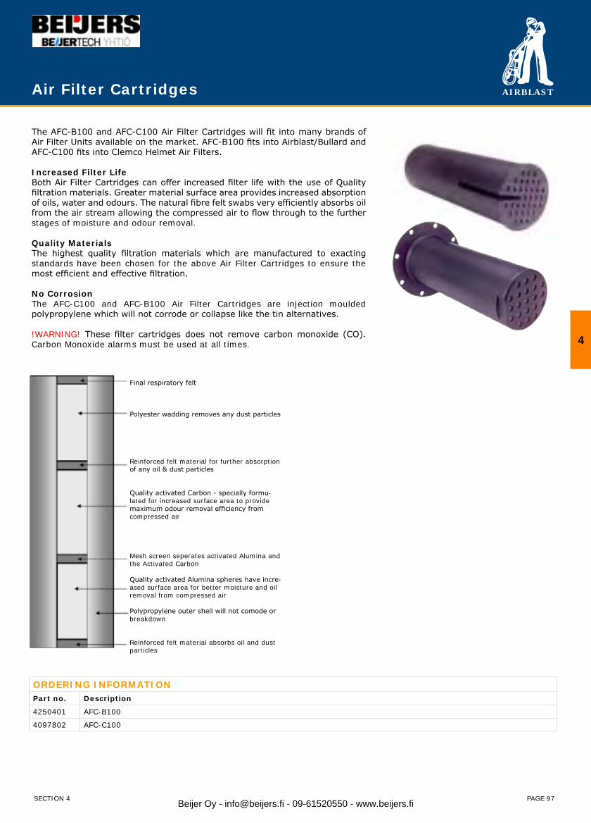
AIRBLAST
PAGE 97
Air Filter Cartridges
The AFC-B100 and AFC-C100 Air Filter Cartridges will fit into many brands of Air Filter Units available on the market. AFC-B100 fits into Airblast/Bullard and AFC-C100 fits into Clemco Helmet Air Filters.
Increased Filter LifeBoth Air Filter Cartridges can offer increased filter life with the use of Quality filtration materials. Greater material surface area provides increased absorption of oils, water and odours. The natural fibre felt swabs very efficiently absorbs oil from the air stream allowing the compressed air to flow through to the further stages of moisture and odour removal.
Quality MaterialsThe highest quality filtration materials which are manufactured to exacting standards have been chosen for the above Air Filter Cartridges to ensure the most efficient and effective filtration. No CorrosionThe AFC-C100 and AFC-B100 Air Filter Cartridges are injection moulded polypropylene which will not corrode or collapse like the tin alternatives.
!WARNING! These filter cartridges does not remove carbon monoxide (CO). Carbon Monoxide alarms must be used at all times.
ORDERING INFORMATIONPart no. Description
4250401 AFC-B100
4097802 AFC-C100
Final respiratory felt
Polyester wadding removes any dust particles
Reinforced felt material for further absorption of any oil & dust particles
Quality activated Carbon - specially formu-lated for increased surface area to provide maximum odour removal efficiency from compressed air
Mesh screen seperates activated Alumina and the Activated Carbon
Quality activated Alumina spheres have incre-ased surface area for better moisture and oil removal from compressed air
Polypropylene outer shell will not comode or breakdown
Reinforced felt material absorbs oil and dust particles
SECTION 4
4
Beijer Oy - [email protected] - 09-61520550 - www.beijers.fi
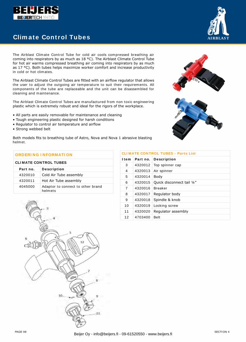
AIRBLAST
PAGE 98
The Airblast Climate Control Tube for cold air cools compressed breathing air coming into respirators by as much as 18 °C). The Airblast Climate Control Tube for hot air warms compressed breathing air coming into respirators by as much as 17 °C). Both tubes helps maximize worker comfort and increase productivity in cold or hot climates.
The Airblast Climate Control Tubes are fitted with an airflow regulator that allows the user to adjust the outgoing air temperature to suit their requirements. All components of the tube are replaceable and the unit can be disassembled for cleaning and maintenance.
The Airblast Climate Control Tubes are manufactured from non toxic engineering plastic which is extremely robust and ideal for the rigors of the workplace.
• All parts are easily removable for maintenance and cleaning • Tough engineering plastic designed for harsh conditions • Regulator to control air temperature and airflow • Strong webbed belt
Both models fits to breathing tube of Astro, Nova and Nova 1 abrasive blasting helmet.
Climate Control Tubes
ORDERING INFORMATION
CLIMATE CONTROL TUBES
Part no. Description4320010 Cold Air Tube assembly4320011 Hot Air Tube assembly4045000 Adaptor to connect to other brand
helmets
CLIMATE CONTROL TUBES - Parts ListItem Part no. Description
3 4320012 Top spinner cap4 4320013 Air spinner5 4320014 Body6 4320015 Quick disconnect tail ¼” 7 4320016 Breaker8 4320017 Regulator body9 4320018 Spindle & knob10 4320019 Locking screw11 4320020 Regulator assembly12 4703400 Belt
SECTION 4Beijer Oy - [email protected] - 09-61520550 - www.beijers.fi
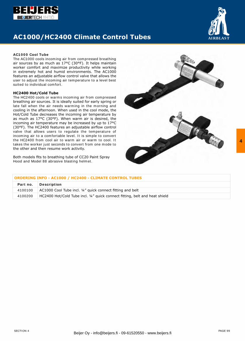
AIRBLAST
PAGE 99
AC1000/HC2400 Climate Control Tubes
AC1000 Cool TubeThe AC1000 cools incoming air from compressed breathing air sources by as much as 17°C (30°F). It helps maintain worker comfort and maximize productivity while working in extremely hot and humid environments. The AC1000 features an adjustable airflow control valve that allows the user to adjust the incoming air temperature to a level best suited to individual comfort.
HC2400 Hot/Cold TubeThe HC2400 cools or warms incoming air from compressed breathing air sources. It is ideally suited for early spring or late fall when the air needs warming in the morning and cooling in the afternoon. When used in the cool mode, the Hot/Cold Tube decreases the incoming air temperature by as much as 17°C (30°F). When warm air is desired, the incoming air temperature may be increased by up to 17°C (30°F). The HC2400 features an adjustable airflow control valve that allows users to regulate the temperature of incoming air to a comfortable level. It is simple to convert the HC2400 from cool air to warm air or warm to cool. It takes the worker just seconds to convert from one mode to the other and then resume work activity.
Both models fits to breathing tube of CC20 Paint Spray Hood and Model 88 abrasive blasting helmet.
ORDERING INFO - AC1000 / HC2400 - CLIMATE CONTROL TUBES
Part no. Description4100100 AC1000 Cool Tube incl. ¼” quick connect fitting and belt 4100200 HC2400 Hot/Cold Tube incl. ¼” quick connect fitting, belt and heat shield
SECTION 4
4
Beijer Oy - [email protected] - 09-61520550 - www.beijers.fi
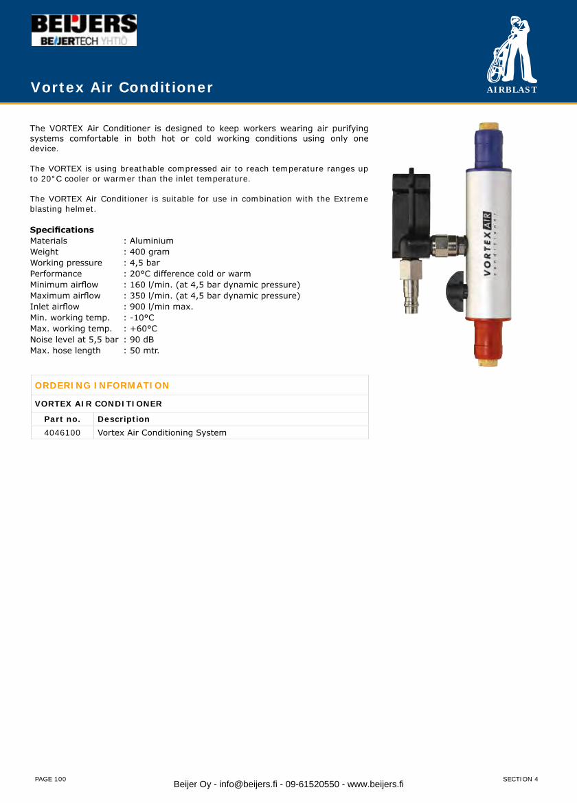
AIRBLAST
PAGE 100
Vortex Air Conditioner
The VORTEX Air Conditioner is designed to keep workers wearing air purifying systems comfortable in both hot or cold working conditions using only one device.
The VORTEX is using breathable compressed air to reach temperature ranges up to 20°C cooler or warmer than the inlet temperature.
The VORTEX Air Conditioner is suitable for use in combination with the Extreme blasting helmet.
SpecificationsMaterials : AluminiumWeight : 400 gramWorking pressure : 4,5 barPerformance : 20°C difference cold or warmMinimum airflow : 160 l/min. (at 4,5 bar dynamic pressure)Maximum airflow : 350 l/min. (at 4,5 bar dynamic pressure)Inlet airflow : 900 l/min max.Min. working temp. : -10°CMax. working temp. : +60°CNoise level at 5,5 bar : 90 dBMax. hose length : 50 mtr.
ORDERING INFORMATION
VORTEX AIR CONDITIONER
Part no. Description4046100 Vortex Air Conditioning System
SECTION 4Beijer Oy - [email protected] - 09-61520550 - www.beijers.fi
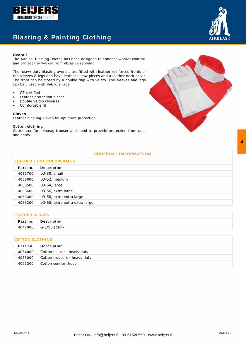
AIRBLAST
PAGE 101
OverallThe Airblast Blasting Overall has been designed to enhance worker comfort and protect the worker from abrasive rebound.
The heavy duty blasting overalls are fitted with leather reinforced fronts of the sleeves & legs and have leather elbow pieces and a leather neck collar. The front can be closed by a double flap with velcro. The sleeves and legs can be closed with Velcro straps.
CE certified• Leather protection pieces• Double velcro closures• Comfortable fit •
GlovesLeather blasting gloves for optimum protection.
Cotton clothingCotton comfort blouse, trouser and hood to provide protection from dust and spray.
ORDERING INFORMATION
LEATHER / COTTON OVERALLS
Part no. Description4053700 LO-50, small4053600 LO-52, medium4053500 LO-54, large4053400 LO-56, extra large4053300 LO-58, extra extra large4053200 LO-60, extra extra extra large
LEATHER GLOVES
Part no. Description4047000 G-L/90 (pair)
COTTON CLOTHING
Part no. Description4054000 Cotton blouse - heavy duty4055000 Cotton trousers - heavy duty4053300 Cotton comfort hood
Blasting & Painting Clothing
SECTION 4
4
Beijer Oy - [email protected] - 09-61520550 - www.beijers.fi

AIRBLAST
PAGE 102
GX4 Gas Detection Monitor
As you know, compressed breathing air can create a deadly environment. Do you have an intelligent gas monitor which can give you complete confidence in the air you and your employees are breathing? The GX4 is your solution. With the ability to detect up to 4 gases and with traceability the GX4 gives you a perfect solution.
Gases like Carbon Monoxide are invisible to all the human senses, yet are commonly found in industrial premises’ worldwide. While low level carbon monoxide exposure may not be immediately fatal to employee’s, ongoing contact with the gas at low levels has a cumulative effect, causing serious illness and health concerns for employee’s long term. With symptoms often confused with the flu, headaches or tiredness, it’s a serious problem which is often too easily ignored.
APPLICATIONS:• Spray painting• Blasting and confined space application• Chemical handling• And many more!
FEATURES:• Illuminated information display for viewing real time data.• 103 decibel alarm. This can also be used in conjunction with auxiliary warning devices such as strobe lights.• Monitor up to four gases simultaneously.• Strong purpose built case, made from from reinforced polypropylene it is designed for the harshest of conditions.• Cartridges can be easily replaced.• Sturdy mounting bracket for attaching the GX4 to walls or HAF Helmet Air Filter.• Universal power options for running the GX4 or charging it’s internal battery.• If you are working remotely to the GX4 Gas Monitor you can connect a strobe light or strobe light and alarm.• Complete quick and easy calibration checks with no set points required.• A range of pre-calibrated gas sensors are available including CO, O2 and CO2 and all have a 2 year shelf life.• Connect from your laptop, tablet, phone or a network to view real time data, download logs and much more.• Optional robust carry case
SECTION 4Beijer Oy - [email protected] - 09-61520550 - www.beijers.fi
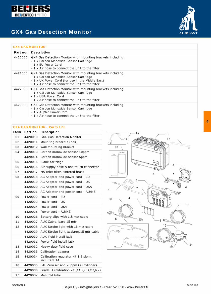
AIRBLAST
PAGE 103
GX4 Gas Detection Monitor
GX4 GAS MONITOR
Part no. Description4420000 GX4 Gas Detection Monitor with mounting brackets including:
- 1 x Carbon Monoxide Sensor Cartridge- 1 x EU Power Cord- 1 x Air hose to connect the unit to the filter
4421000 GX4 Gas Detection Monitor with mounting brackets including:- 1 x Carbon Monoxide Sensor Cartridge- 1 x UK Power Cord (for use in the Middle East)- 1 x Air hose to connect the unit to the filter
4422000 GX4 Gas Detection Monitor with mounting brackets including:- 1 x Carbon Monoxide Sensor Cartridge- 1 x USA Power Cord- 1 x Air hose to connect the unit to the filter
4423000 GX4 Gas Detection Monitor with mounting brackets including:- 1 x Carbon Monoxide Sensor Cartridge- 1 x AU/NZ Power Cord- 1 x Air hose to connect the unit to the filter
GX4 GAS MONITOR - Parts ListItem Part no. Description
01 4420010 GX4 Gas Detection Monitor02 4420011 Mounting brackets (pair)03 4420012 Wall mounting bracket 04 4420013 Carbon monoxide sensor 10ppm
4420014 Carbon monoxide sensor 5ppm 05 4420015 Blank cartridge06 4420016 Air supply hose & one touch connector 07 4420017 M5 Inlet filter, sintered brass 08 4420018 AC Adaptor and power cord - EU
4420019 AC Adaptor and power cord - UK4420020 AC Adaptor and power cord - USA4420021 AC Adaptor and power cord - AU/NZ
09 4420022 Power cord - EU 4420023 Power cord - UK4420024 Power cord - USA4420025 Power cord - AU/NZ
10 4420026 Battery clips with 1.8 mtr cable11 4420027 AUX Cable, bare 15 mtr12 4420028 AUX Strobe light with 15 mtr cable
4420029 AUX Strobe light w/alarm,15 mtr cable 4420030 AUX Field install jack4420031 Power field install jack
13 4420032 Heavy duty field case 14 4420033 Calibration adaptor 15 4420034 Calibration regulator kit 1.5 slpm,
incl. item 14 16 4420035 34L Zero air and 20ppm CO cylinders
4420036 Grade D calibration kit (CO2,CO,O2,N2)17 4420037 Manifold tube
SECTION 4
4
1
2
3
4
5
6
8
7
15
16
14
13
12
11
10
17
9
Beijer Oy - [email protected] - 09-61520550 - www.beijers.fi

AIRBLAST
PAGE 104
SPARE PARTS FOR ABKR-12/2 AND ABKR-24/20
Item Part no. Description1 5010700 Halogen bulb 12 Volt / 20 Watt
5010200 Halogen bulb 24 Volt / 20 Watt
5016500 LED bulb 12 Volt / 4 Watt
2 5010300 Lens
3 5010400 CEE Connector, 2 poles, 16A (Male)
4 5009500 Cable (2 x 0.75 mm²), black rubber, RWPK H05RN-F
5010500 Cable (2 x 1.50 mm²), black rubber, RWPK H05RN-F
5012000 Cable (2 x 1.50 mm²), neoprene, NWPK H07RN-F
5 5012100 Fitting
6 5012200 Spring clip
7 5012300 Cable connector
8 5012400 Rubber plug
9 5012500 Clamp
10 5012600 Bolt (not shown)
Airblast Blast Lights are developed to meet the demand for an easy to use, lightweight, low voltage abrasive blasting light.
Features:Highly concentrated output of halogen/LED light, the unit fully • illuminates the area on which blasting is taking place.Safe to use – works with 12 or 24 volt power supply and there’s no • glass to break - a cheap, strong and easily replaceable plastic lens is used at the front of the unit.No light spill or dazzle – by using a special bulb and tube fitting, the • light is concentrated only on the work area and all back dazzle is eliminated.Free to work – because the unit is clamped directly on the blast • nozzle fitting, the operator has both hands free to operate the blast equipment.The blast light can be used alongside all existing deadman handles.•
To back up the light, a suitable fully rubber housed transformer is available to connect to a 220 volt 50 hz line, giving a 12 volt output to upto 4 separate sockets for up to 4 lights. Other executions are available on request.
Blast Lights (LED) 12V / 24V
ORDERING INFORMATIONBLAST LIGHT ABKR
5010800 ABKR-12/20 Blast Light 12 Volt/20 Watt incl. 12 Volt halo bulb, 5 m cable (2 x 0.75 mm²) and CEE-Connector (Male).
5010100 ABKR-24/20 Blast Light 24 Volt/20 Watt incl. 24 Volt halo bulb, 5 m cable (2 x 0.75 mm²) and CEE-Connector (Male).
5016000 ABKR-12/4 Blast Light 12 Volt/4 Watt incl. 12 Volt LED bulb, 5 m cable (2 x 0.75 mm²) and CEE-Connector (Male).
SECTION 4Beijer Oy - [email protected] - 09-61520550 - www.beijers.fi

AIRBLAST
PAGE 105
BLAST LIGHT HALO
5011000 HALO-24/100 BLAST LIGHT 24 Volt / 100 Watt with ON/OFF-Switch, Full Rubber housing with reflector. Incl. halogen bulb, 5 m cable (2 x 1.5 mm²) and CEE Connector (M) * Also available in 12 Volt and 42 Volt execution.
5020000 HALO-24/100 BLAST LIGHT 24 Volt / 100 Watt. Full Rubber housing with reflector. Incl. halogen bulb, 5 m cable (2 x 1.5 mm²) and CEE Connector (M).
SPARE PARTS FOR HALO-24/100
Item Part no. Description1 5011100 Bulb 24 Volt / 100 Watt
2 5010400 CEE Connector 24V / 16A (M)
3 5012000 Cable (2 x 1.50 mm²), neoprene, NWPK H07RN-F
5013000 Cable (2 x 2.50 mm²), neoprene, NWPK H07RN-F
4 5012700 Rubber plug
TRANSFORMERS FOR 24V BLAST AND FLOOD LIGHTS. Incl. 3 m (2 x 1.5 mm2) Grounded cable and 24 Volt 16A CEE Output (Female) - Full rubber housing. Thermal Safeguard against overload.5011500 TRANS MINI - 220V / 24V 120VA - 1 x 24 Volt / 16A CEE output (F)
5011600 TRANS-MIDI - 220V / 24V 225VA - 2 x 24 Volt / 16A CEE-output (F)
5030100 TRANS I/1 - 220V / 24V 500VA - 1 x 24 Volt / 16A CEE output (F)
5030200 TRANS I/2 - 220V / 24V 500VA - 2 x 24 Volt / 16A CEE output (F)
5030300 TRANS I/3 - 220V / 24V 500VA - 3 x 24 Volt / 16A CEE output (F)
5030400 TRANS I/4 - 220V / 24V 500VA - 4 x 24 Volt / 16A CEE output (F)
5030500 TRANS II/2 - 220V / 24V 1000VA - 2 x 24 Volt / 16A CEE output (F)
5030600 TRANS II/3 - 220V / 24V 1000VA - 3 x 24 Volt / 16A CEE output (F)
5030700 TRANS II/4 - 220V / 24V 1000VA - 4 x 24 Volt / 16A CEE output (F)
Blast Lights
4
SECTION 4 Beijer Oy - [email protected] - 09-61520550 - www.beijers.fi
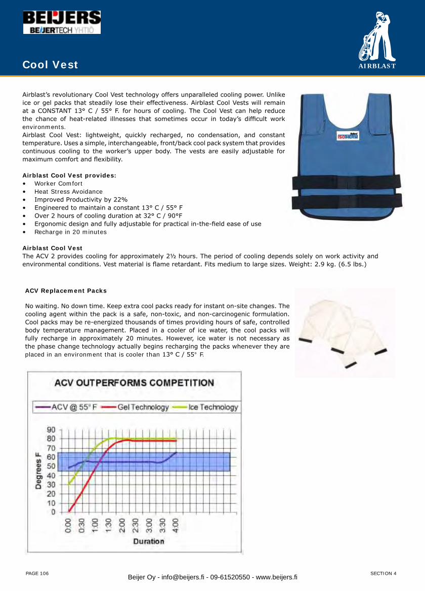
AIRBLAST
PAGE 106
Airblast’s revolutionary Cool Vest technology offers unparalleled cooling power. Unlike ice or gel packs that steadily lose their effectiveness. Airblast Cool Vests will remain at a CONSTANT 13° C / 55° F. for hours of cooling. The Cool Vest can help reduce the chance of heat-related illnesses that sometimes occur in today’s difficult work environments.Airblast Cool Vest: lightweight, quickly recharged, no condensation, and constant temperature. Uses a simple, interchangeable, front/back cool pack system that provides continuous cooling to the worker’s upper body. The vests are easily adjustable for maximum comfort and flexibility.
Airblast Cool Vest provides:Worker Comfort• Heat Stress Avoidance• Improved Productivity by 22%• Engineered to maintain a constant 13° C / 55° F• Over 2 hours of cooling duration at 32° C / 90°F• Ergonomic design and fully adjustable for practical in-the-field ease of use• Recharge in 20 minutes•
Airblast Cool VestThe ACV 2 provides cooling for approximately 2½ hours. The period of cooling depends solely on work activity and environmental conditions. Vest material is flame retardant. Fits medium to large sizes. Weight: 2.9 kg. (6.5 lbs.)
ACV Replacement Packs
No waiting. No down time. Keep extra cool packs ready for instant on-site changes. The cooling agent within the pack is a safe, non-toxic, and non-carcinogenic formulation. Cool packs may be re-energized thousands of times providing hours of safe, controlled body temperature management. Placed in a cooler of ice water, the cool packs will fully recharge in approximately 20 minutes. However, ice water is not necessary as the phase change technology actually begins recharging the packs whenever they are placed in an environment that is cooler than 13° C / 55° F.
Cool Vest
SECTION 4Beijer Oy - [email protected] - 09-61520550 - www.beijers.fi

AIRBLAST
PAGE 107
Product PageAquastorm abrasive wet blasting system 108Aquablast wetblast attachment 109WIN Water injection nozzles 110Educt-O-Matic portable dust free vacuum blaster 111AB-1020 EP Dust free vacuum blast machine 114AB-1030 EP/PN Dust free vacuum blast machine 115AB-1050 EP/PN Dust free vacuum blast machine 116AB-1060 EP/PN Dust free vacuum blast machine 118AB-1070 EP/PN Dust free vacuum blast machine 120AB-61 Vacuum injection cabinet 122AB-90 Vacuum injection cabinet 123ABDI-1000 Vacuum injection cabinet 124ABDI-1300 Vacuum injection cabinet 125ABD-1000 Pressure blast cabinet 126ABD-1250 Pressure blast cabinet 127ABD-1300 Pressure blast cabinet 128ABD-1500 Pressure blast cabinet 129
Blastrooms 130UHP High Pressure Waterjetting 131
Section 5 - Dust Free
5
SECTION 5 Beijer Oy - [email protected] - 09-61520550 - www.beijers.fi
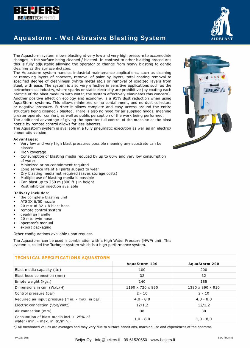
AIRBLAST
PAGE 108
Aquastorm - Wet Abrasive Blasting System
The Aquastorm system allows blasting at very low and very high pressure to accomodate changes in the surface being cleaned / blasted. In contrast to other blasting procedures this is fully adjustable allowing the operator to change from heavy blasting to gentle cleaning as the surface dictates.The Aquastorm system handles industrial maintenance applications, such as cleaning or removing layers of concrete, removal of paint by layers, total coating removal to specified degree of cleanliness (white metal etc.) or removal of oxidized layers from steel, with ease. The system is also very effective in sensitive applications such as the petrochemical industry, where sparks or static electricity are prohibitive (by coating each particle of the blast medium with water, the system effectively eliminates this concern).Another positive effect on ecology and economy, is a 95% dust reduction when using AquaStorm systems. This allows minimized or no containment, and no dust collectors or negative pressure. Further it allows complete and easy access around the entire structure being cleaned / blasted. There is also no need for air supplied hoods, meaning greater operator comfort, as well as public perception of the work being performed.The additional advantage of giving the operator full control of the machine at the blast nozzle by remote control allows for less laborers.The Aquastorm system is available in a fully pneumatic execution as well as an electric/ pneumatic version.
Advantages:• Very low and very high blast pressures possible meaning any substrate can be blasted • High coverage• Consumption of blasting media reduced by up to 60% and very low consumption of water • Minimized or no containment required• Long service life of all parts subject to wear• Dry blasting media not required (saves storage costs)• Multiple use of blasting media is possible• Can blast up to 250 m (800 ft.) in height• Rust inhibitor injection available
Delivery includes:the complete blasting unit• ATSDX 6/50 nozzle• 20 mtr of 32 x 8 blast hose• remote control system• deadman handle• 20 mtr. twin hose• operator’s manual• export packaging•
Other configurations available upon request.
The Aquastorm can be used is combination with a High Water Pressure (HWP) unit. This system is called the Turbojet system which is a high performance system.
TECHNICAL SPECIFICATIONS AQUASTORMAquaStorm 100 AquaStorm 200
Blast media capacity (ltr.) 100 200Blast hose connection (mm) 32 32Empty weight (kgs.) 140 185Dimensions in cm. (WxLxH) 1190 x 720 x 850 1380 x 890 x 910Control pressure (bar) 2 - 10 2 - 10Required air input pressure (min. - max. in bar) 4,0 - 8,0 4,0 - 8,0Electric connection (Volt/Watt) 12/1,2 12/1,2Air connection (mm) 38 38Consumtion of blast media incl. ± 25% ofwater (min. - max. in ltr./min.) 1,0 - 8,0 1,0 - 8,0
*) All mentioned values are averages and may vary due to surface conditions, machine use and experiences of the operator.
SECTION 5Beijer Oy - [email protected] - 09-61520550 - www.beijers.fi
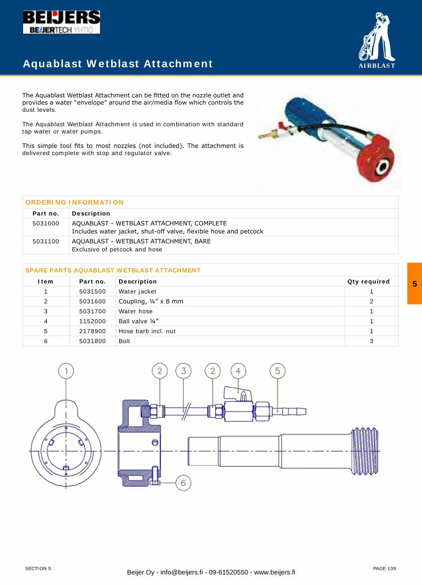
AIRBLAST
PAGE 109
Aquablast Wetblast Attachment
The Aquablast Wetblast Attachment can be fitted on the nozzle outlet and provides a water “envelope” around the air/media flow which controls the dust levels.
The Aquablast Wetblast Attachment is used in combination with standard tap water or water pumps.
This simple tool fits to most nozzles (not included). The attachment is delivered complete with stop and regulator valve.
ORDERING INFORMATIONPart no. Description5031000 AQUABLAST - WETBLAST ATTACHMENT, COMPLETE
Includes water jacket, shut-off valve, flexible hose and petcock5031100 AQUABLAST - WETBLAST ATTACHMENT, BARE
Exclusive of petcock and hose
SPARE PARTS AQUABLAST WETBLAST ATTACHMENT
Item Part no. Description Qty required1 5031500 Water jacket 12 5031600 Coupling, ¼” x 8 mm 23 5031700 Water hose 14 1152000 Ball valve ¼” 15 2178900 Hose barb incl. nut 16 5031800 Bolt 3
5
SECTION 5 Beijer Oy - [email protected] - 09-61520550 - www.beijers.fi

AIRBLAST
PAGE 110
WIN Water Injection Nozzles
Airblast high velocity venturi style nozzles have been designed specifically to give maximum blast cleaning rates, uniform abrasive distribution and efficiency over an extensive operating life. Through the venturi principle the air and abrasive mixture is accelerated as it exits the nozzle. Venturi nozzles increase productivity and reduce abrasive consumption with approximately 40% as compared to straight bore nozzles. Airblast offers a full selection of nozzles with different orifice diameters, sizes, and insert / jacket materials.
WIN NozzleThe WIN (Water Injection Nozzle) system is a simple, cost effective solution for high production, wet abrasive blasting that can be used with your existing pressure blast equipment. The system can be used with water from a tap or with rust inhibitors supplied through any simple pump. No special equipment is required. The WIN system offers the highest performance possible in wet abrasive blasting technology.
ORDERING INFORMATION
Part no. Description Orifice Lenght Inlet
2460000 WIN-4/50 Water Injection Nozzle 6,4 mm 149 mm 25 mm
2461000 WIN-5/50 Water Injection Nozzle 7,9 mm 158 mm 25 mm
2462000 WIN-6/50 Water Injection Nozzle 9,5 mm 171 mm 25 mm
2463000 WIN-8/50 Water Injection Nozzle 12 mm 227 mm 25 mm
SECTION 5Beijer Oy - [email protected] - 09-61520550 - www.beijers.fi
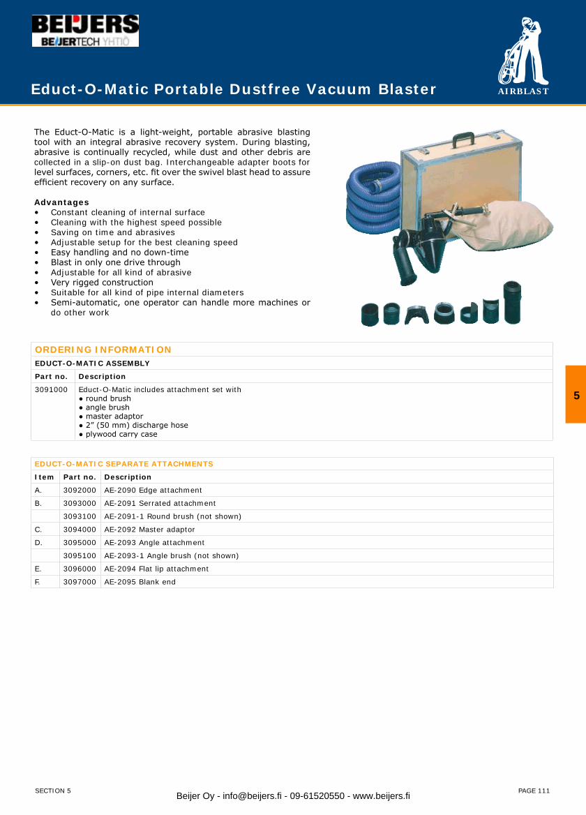
AIRBLAST
PAGE 111
The Educt-O-Matic is a light-weight, portable abrasive blasting tool with an integral abrasive recovery system. During blasting, abrasive is continually recycled, while dust and other debris are collected in a slip-on dust bag. Interchangeable adapter boots for level surfaces, corners, etc. fit over the swivel blast head to assure efficient recovery on any surface.
AdvantagesConstant cleaning of internal surface• Cleaning with the highest speed possible• Saving on time and abrasives• Adjustable setup for the best cleaning speed• Easy handling and no down-time• Blast in only one drive through• Adjustable for all kind of abrasive• Very rigged construction• Suitable for all kind of pipe internal diameters• Semi-automatic, one operator can handle more machines or • do other work
Educt-O-Matic Portable Dustfree Vacuum Blaster
EDUCT-O-MATIC SEPARATE ATTACHMENTS
Item Part no. Description
A. 3092000 AE-2090 Edge attachment
B. 3093000 AE-2091 Serrated attachment
3093100 AE-2091-1 Round brush (not shown)
C. 3094000 AE-2092 Master adaptor
D. 3095000 AE-2093 Angle attachment
3095100 AE-2093-1 Angle brush (not shown)
E. 3096000 AE-2094 Flat lip attachment
F. 3097000 AE-2095 Blank end
ORDERING INFORMATIONEDUCT-O-MATIC ASSEMBLY
Part no. Description
3091000 Educt-O-Matic includes attachment set with ● round brush● angle brush● master adaptor● 2” (50 mm) discharge hose● plywood carry case
5
SECTION 5 Beijer Oy - [email protected] - 09-61520550 - www.beijers.fi

AIRBLAST
PAGE 112
EDUCT-O-MATIC SPARE PARTS
Item Part no. Description
01. 3098000 AE-2001 Blast head
02. 3099000 AE-2002 Standard adaptor
03. 3100000 AE-2004 ⅜” (9 mm) nozzle – TC
04. 3102000 AE-2006 Blast jet
05. 3103000 AE-2007 Jet gasket
06. 3103100 AE-2008Valve assembly
07. 3104000 AE-2005 Thumb screw
08. 3105000 AE-2011 Blast head nipple ⅜”x4¼” (9 x 108mm)
09. 3106000 AE-2012 Swivel connector
10. 3107000 AE-2013 O-ring
11. 3108000 AE-2014 Main body
12. 3109000 AE-2016 Abrasive hose
13. 3110000 AE-2018 Thumb screw
14. 3110500 AE-2019 Baffle washer
15. 3111000 AE-2020 Hose clamp
16. 3112000 AE-2021 Air hose
17. 3112500 AE-2021-1 Spring for air hose
18. 3113000 AE-2022 Suction jet
19. 3114000 AE-2068-1 Sreen assembly
20. 3115000 AE-2023 Baffle (plastic only)
21. 3344000 AE-2027 Locking device
22. 3116000 AE-2068 Screen
23. 3117000 AE-2030 Screen gasket
24. 3118000 AE-2069 Abrasive container w/lock and hose
25. 3119000 AE-2035 Dust bag
26. 3120000 AE-2032-1 Ejector pipe
27. 3120100 AE-2032-1 Dust bag holder
28. 3121000 AE-2042 Valve body
29. 3122000 AE-2036 O-ring
EDUCT-O-MATIC SPARE PARTS
Item Part no. Description
30. 3122100 AE-2038 Screw
31. 3122200 AE-2039 Washer
32. 3122800 AE-2043 Handle pin
33. 3122900 AE-2044 Snap ring
34. 3123000 AE-2045 Valve bushing
35. 3124000 AE-2046 Valve bushing gasket
36. 3125000 AE-2047 O-ring (neoprene)
37. 3126000 AE-2048 Washer
38. 3127000 AE-2049 Snap ring
39. 3128000 AE-2050 Primary valve spring
40. 3129000 AE-2051 Valve stem
41. 3130000 AE-2052 Primary valve seat
42. 3131000 AE-2053 Guide washer brass
43. 3132000 AE-2054 Hex nut
44. 3133000 AE-2055 Washer brass
45. 3134000 AE-2056 Second valve spring
46. 3135000 AE-2057 Second valve seat
47. 3137000 AE-2059 Washer - brass
48. 3138000 AE-2060 Snap ring
49. 3140000 AE-2061 Pipe nipple
50. 3141000 AE-2083 Rubber tube
51. 3142000 AE-2065 Valve handle assembly
52. 3143000 AE-2070 Swivel nut assembly
53. 2162900 KIG-12 Coupling with F thread
54. 2164000 CQG-0 Rubber gasket
55. 2168400 SKG-19 Coupling w/hose barb 3/4”
56. 2168200 SKG-13 Coupling w/hose barb 1/2”
57. 2172300 HS-32 Hose clamp
58. 3147000 AE-2120 Plywood carrycase
Educt-O-Matic Portable Dustfree Vacuum Blaster
SECTION 5Beijer Oy - [email protected] - 09-61520550 - www.beijers.fi
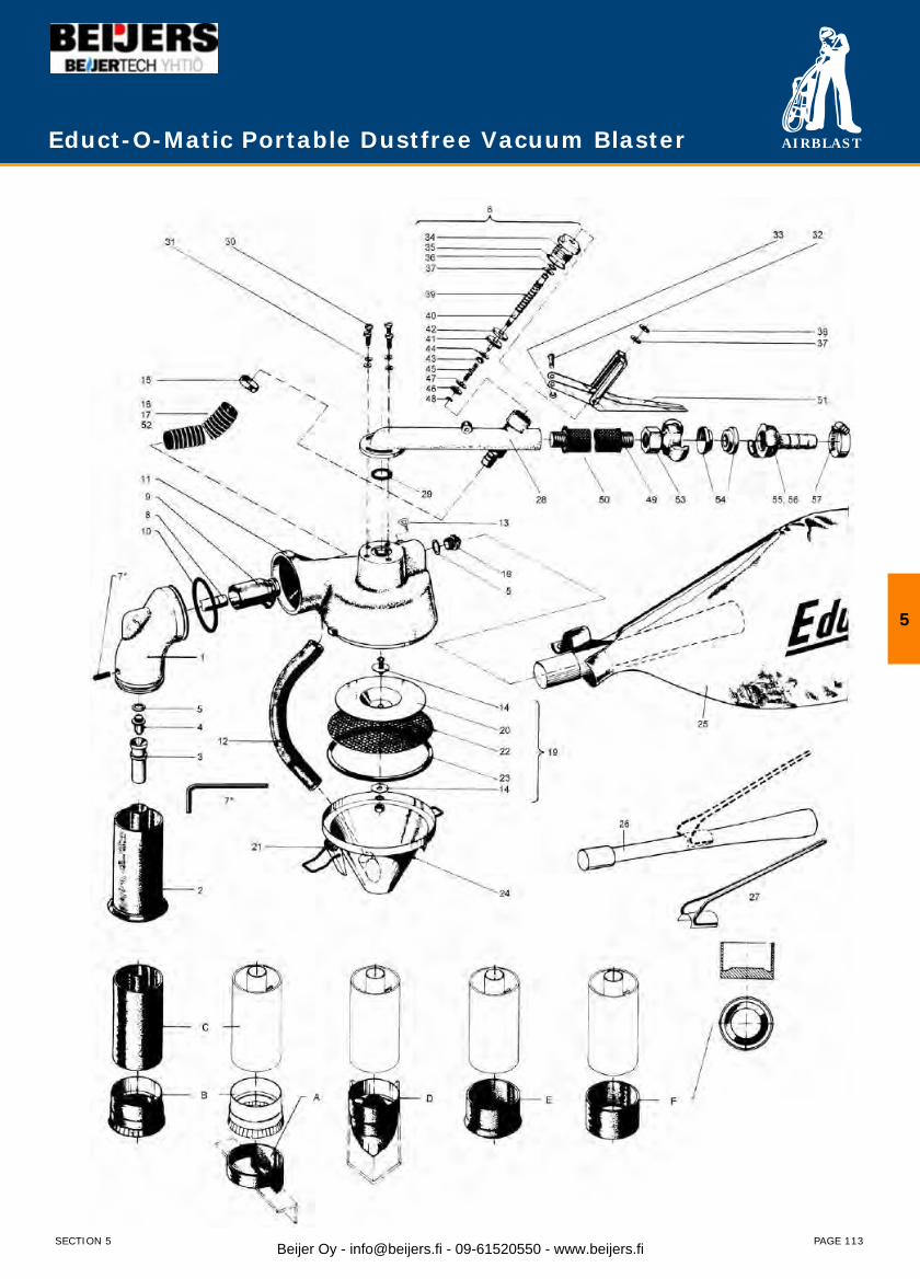
AIRBLAST
PAGE 113
Educt-O-Matic Portable Dustfree Vacuum Blaster
5
SECTION 5 Beijer Oy - [email protected] - 09-61520550 - www.beijers.fi
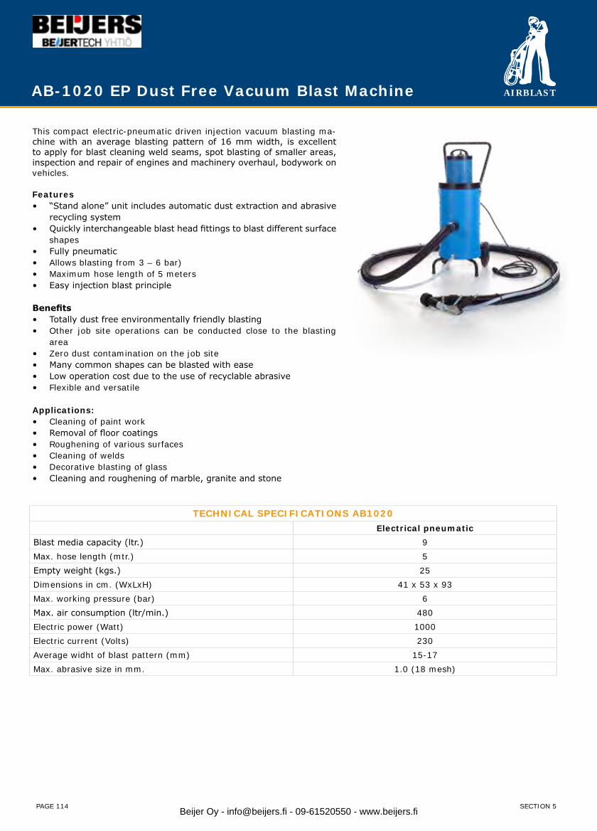
AIRBLAST
PAGE 114
AB-1020 EP Dust Free Vacuum Blast Machine
This compact electric-pneumatic driven injection vacuum blasting ma-chine with an average blasting pattern of 16 mm width, is excellent to apply for blast cleaning weld seams, spot blasting of smaller areas, inspection and repair of engines and machinery overhaul, bodywork on vehicles.
Features“Stand alone” unit includes automatic dust extraction and abrasive • recycling systemQuickly interchangeable blast head fittings to blast different surface • shapesFully pneumatic• Allows blasting from 3 – 6 bar)• Maximum hose length of 5 meters• Easy injection blast principle•
BenefitsTotally dust free environmentally friendly blasting• Other job site operations can be conducted close to the blasting • areaZero dust contamination on the job site• Many common shapes can be blasted with ease• Low operation cost due to the use of recyclable abrasive• Flexible and versatile•
Applications:Cleaning of paint work• Removal of floor coatings• Roughening of various surfaces• Cleaning of welds• Decorative blasting of glass• Cleaning and roughening of marble, granite and stone•
TECHNICAL SPECIFICATIONS AB1020Electrical pneumatic
Blast media capacity (ltr.) 9Max. hose length (mtr.) 5Empty weight (kgs.) 25Dimensions in cm. (WxLxH) 41 x 53 x 93Max. working pressure (bar) 6Max. air consumption (ltr/min.) 480Electric power (Watt) 1000Electric current (Volts) 230Average widht of blast pattern (mm) 15-17Max. abrasive size in mm. 1.0 (18 mesh)
SECTION 5Beijer Oy - [email protected] - 09-61520550 - www.beijers.fi
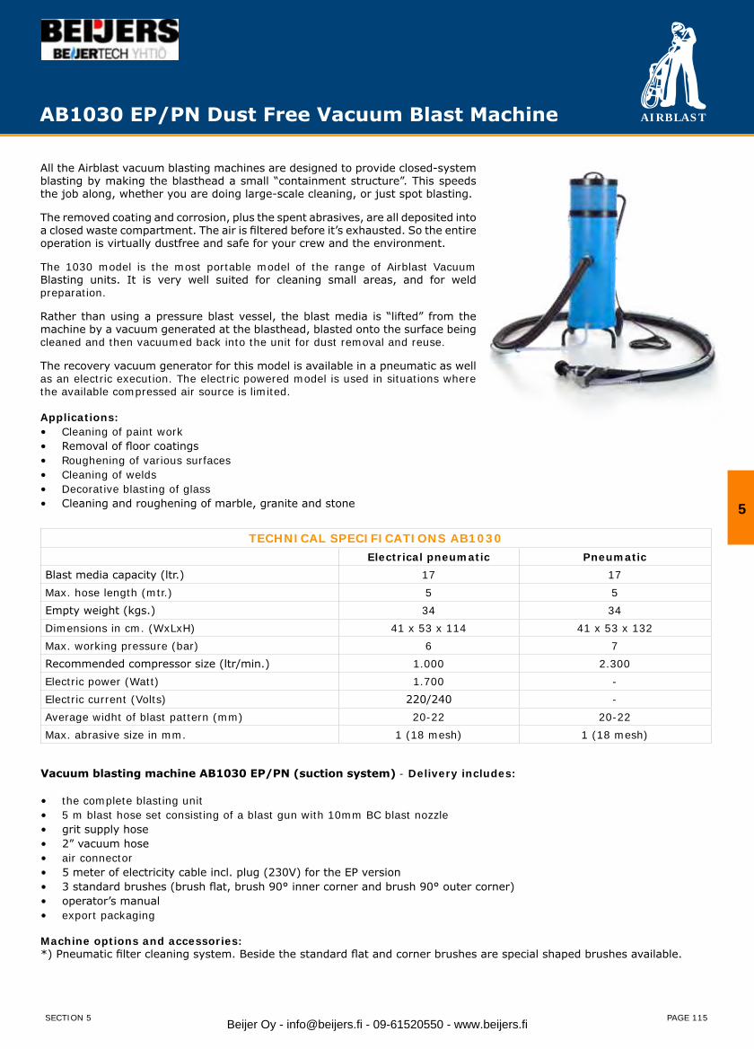
AIRBLAST
PAGE 115
All the Airblast vacuum blasting machines are designed to provide closed-system blasting by making the blasthead a small “containment structure”. This speeds the job along, whether you are doing large-scale cleaning, or just spot blasting.
The removed coating and corrosion, plus the spent abrasives, are all deposited into a closed waste compartment. The air is filtered before it’s exhausted. So the entire operation is virtually dustfree and safe for your crew and the environment.
The 1030 model is the most portable model of the range of Airblast Vacuum Blasting units. It is very well suited for cleaning small areas, and for weld preparation.
Rather than using a pressure blast vessel, the blast media is “lifted” from the machine by a vacuum generated at the blasthead, blasted onto the surface being cleaned and then vacuumed back into the unit for dust removal and reuse.
The recovery vacuum generator for this model is available in a pneumatic as well as an electric execution. The electric powered model is used in situations where the available compressed air source is limited.
Applications:Cleaning of paint work• Removal of floor coatings• Roughening of various surfaces• Cleaning of welds• Decorative blasting of glass• Cleaning and roughening of marble, granite and stone•
TECHNICAL SPECIFICATIONS AB1030Electrical pneumatic Pneumatic
Blast media capacity (ltr.) 17 17Max. hose length (mtr.) 5 5Empty weight (kgs.) 34 34Dimensions in cm. (WxLxH) 41 x 53 x 114 41 x 53 x 132Max. working pressure (bar) 6 7Recommended compressor size (ltr/min.) 1.000 2.300Electric power (Watt) 1.700 -Electric current (Volts) 220/240 -Average widht of blast pattern (mm) 20-22 20-22Max. abrasive size in mm. 1 (18 mesh) 1 (18 mesh)
Vacuum blasting machine AB1030 EP/PN (suction system) - Delivery includes:
the complete blasting unit• 5 m blast hose set consisting of a blast gun with 10mm BC blast nozzle• grit supply hose• 2” vacuum hose• air connector• 5 meter of electricity cable incl. plug (230V) for the EP version• 3 standard brushes (brush flat, brush 90° inner corner and brush 90° outer corner)• operator’s manual• export packaging•
Machine options and accessories:*) Pneumatic filter cleaning system. Beside the standard flat and corner brushes are special shaped brushes available.
AB1030 EP/PN Dust Free Vacuum Blast Machine
5
SECTION 5 Beijer Oy - [email protected] - 09-61520550 - www.beijers.fi
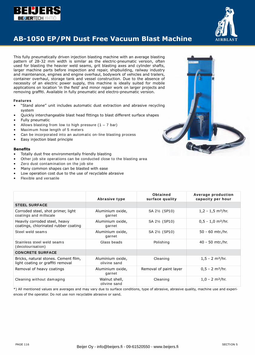
AIRBLAST
PAGE 116
This fully pneumatically driven injection blasting machine with an average blasting pattern of 28-32 mm width is similar as the electric-pneumatic version, often used for blasting the heavier weld seams, grit blasting axes and cylinder shafts, larger machine parts before inspection and repair, shipbuilding, railway industry and maintenance, engines and engine overhaul, bodywork of vehicles and trailers, container overhaul, storage tank and vessel construction. Due to the absence of necessity of an electric power supply, this machine is ideally suited for mobile applications on location ‘in the field’ and minor repair work on larger projects and removing graffiti. Available in fully pneumatic and electro-pneumatic version.
Features“Stand alone” unit includes automatic dust extraction and abrasive recycling • systemQuickly interchangeable blast head fittings to blast different surface shapes• Fully pneumatic• Allows blasting from low to high pressure (1 – 7 bar)• Maximum hose length of 5 meters• Can be incorporated into an automatic on-line blasting process• Easy injection blast principle•
BenefitsTotally dust free environmentally friendly blasting• Other job site operations can be conducted close to the blasting area• Zero dust contamination on the job site• Many common shapes can be blasted with ease• Low operation cost due to the use of recyclable abrasive• Flexible and versatile•
Abrasive typeObtained
surface qualityAverage productioncapacity per hour
STEEL SURFACECorroded steel, shot primer, light coatings and millscale
Aluminium oxide,garnet
SA 2½ (SP10) 1,2 - 1,5 m²/hr.
Heavily corroded steel, heavycoatings, chlorinated rubber coating
Aluminium oxide,garnet
SA 2½ (SP10) 0,5 - 1,0 m²/hr.
Steel weld seams Aluminium oxide,garnet
SA 2½ (SP10) 50 - 60 mtr./hr.
Stainless steel weld seams(decolourisation)
Glass beads Polishing 40 - 50 mtr./hr.
CONCRETE SURFACEBricks, natural stones. Cement film, light coating or graffiti removal
Aluminium oxide,olivine sand
Cleaning 1,5 - 2 m²/hr.
Removal of heavy coatings Aluminium oxide,garnet
Removal of paint layer 0,5 - 2 m²/hr.
Cleaning without damaging Walnut shell,olivine sand
Cleaning 1,0 - 2 m²/hr.
*) All mentioned values are averages and may vary due to surface conditions, type of abrasive, abrasive quality, machine use and experi-ences of the operator. Do not use non recyclable abrasive or sand.
AB-1050 EP/PN Dust Free Vacuum Blast Machine
SECTION 5Beijer Oy - [email protected] - 09-61520550 - www.beijers.fi
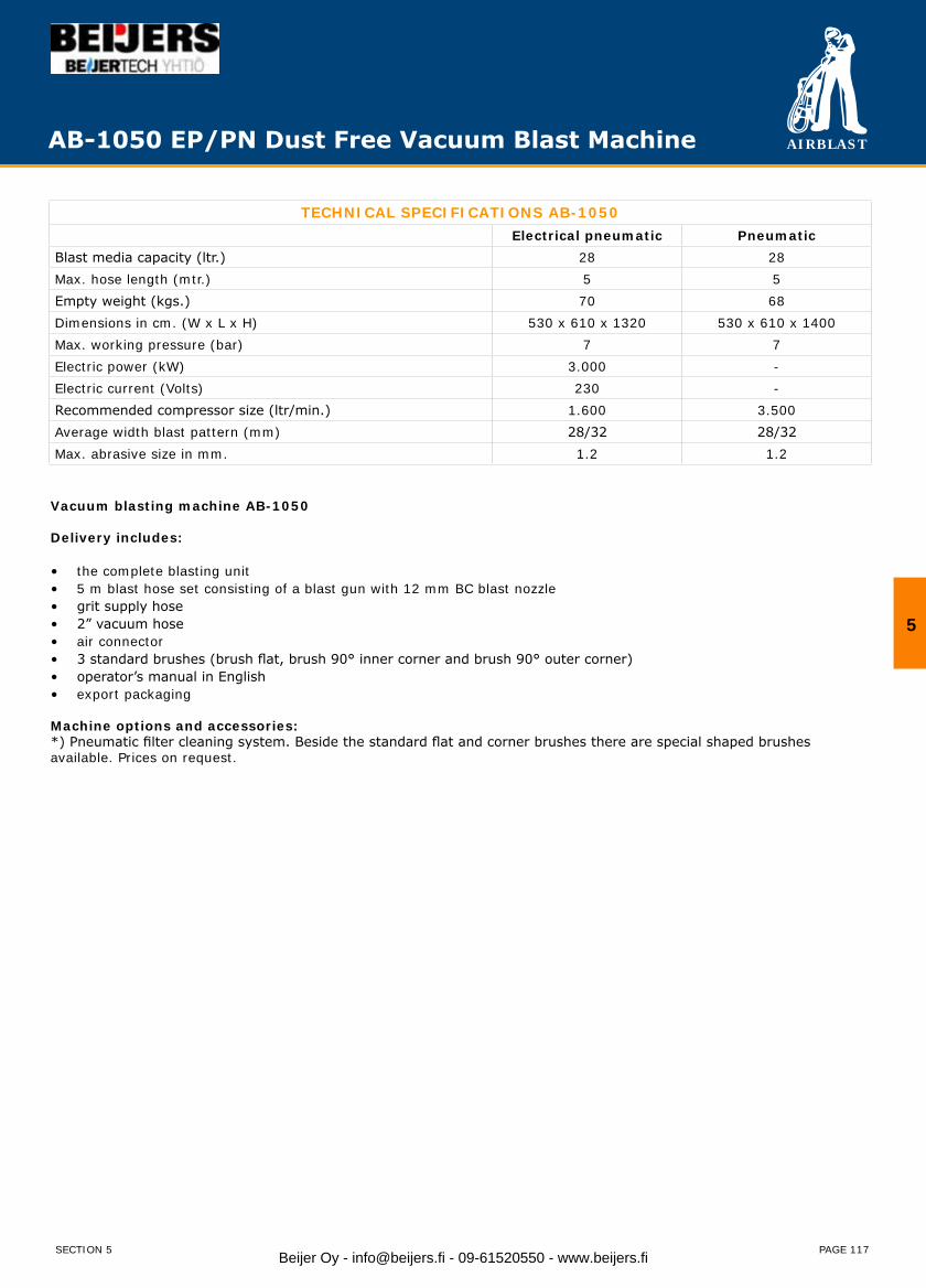
AIRBLAST
PAGE 117
Vacuum blasting machine AB-1050
Delivery includes:
the complete blasting unit•5 m blast hose set consisting of a blast gun with 12 mm BC blast nozzle•grit supply hose•2” vacuum hose•air connector•3 standard brushes (brush flat, brush 90° inner corner and brush 90° outer corner)•operator’s manual in English•export packaging•
Machine options and accessories:*) Pneumatic filter cleaning system. Beside the standard flat and corner brushes there are special shaped brushes available. Prices on request.
TECHNICAL SPECIFICATIONS AB-1050Electrical pneumatic Pneumatic
Blast media capacity (ltr.) 28 28Max. hose length (mtr.) 5 5Empty weight (kgs.) 70 68Dimensions in cm. (W x L x H) 530 x 610 x 1320 530 x 610 x 1400Max. working pressure (bar) 7 7Electric power (kW) 3.000 -Electric current (Volts) 230 -Recommended compressor size (ltr/min.) 1.600 3.500Average width blast pattern (mm) 28/32 28/32Max. abrasive size in mm. 1.2 1.2
AB-1050 EP/PN Dust Free Vacuum Blast Machine
5
SECTION 5 Beijer Oy - [email protected] - 09-61520550 - www.beijers.fi
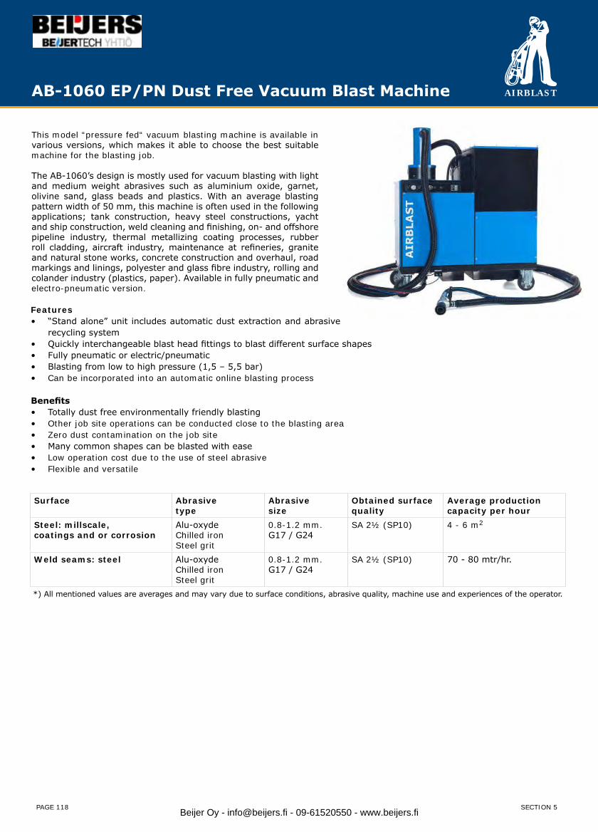
AIRBLAST
PAGE 118
This model “pressure fed“ vacuum blasting machine is available in various versions, which makes it able to choose the best suitable machine for the blasting job.
The AB-1060’s design is mostly used for vacuum blasting with light and medium weight abrasives such as aluminium oxide, garnet, olivine sand, glass beads and plastics. With an average blasting pattern width of 50 mm, this machine is often used in the following applications; tank construction, heavy steel constructions, yacht and ship construction, weld cleaning and finishing, on- and offshore pipeline industry, thermal metallizing coating processes, rubber roll cladding, aircraft industry, maintenance at refineries, granite and natural stone works, concrete construction and overhaul, road markings and linings, polyester and glass fibre industry, rolling and colander industry (plastics, paper). Available in fully pneumatic and electro-pneumatic version.
Surface Abrasivetype
Abrasivesize
Obtained surface quality
Average productioncapacity per hour
Steel: millscale, coatings and or corrosion
Alu-oxydeChilled ironSteel grit
0.8-1.2 mm.G17 / G24
SA 2½ (SP10) 4 - 6 m2
Weld seams: steel Alu-oxydeChilled ironSteel grit
0.8-1.2 mm. G17 / G24
SA 2½ (SP10) 70 - 80 mtr/hr.
*) All mentioned values are averages and may vary due to surface conditions, abrasive quality, machine use and experiences of the operator.
AB-1060 EP/PN Dust Free Vacuum Blast Machine
Features“Stand alone” unit includes automatic dust extraction and abrasive•recycling systemQuickly interchangeable blast head fittings to blast different surface shapes•Fully pneumatic or electric/pneumatic•Blasting from low to high pressure (1,5 – 5,5 bar)•Can be incorporated into an automatic online blasting process•
BenefitsTotally dust free environmentally friendly blasting•Other job site operations can be conducted close to the blasting area•Zero dust contamination on the job site•Many common shapes can be blasted with ease•Low operation cost due to the use of steel abrasive•Flexible and versatile•
SECTION 5Beijer Oy - [email protected] - 09-61520550 - www.beijers.fi
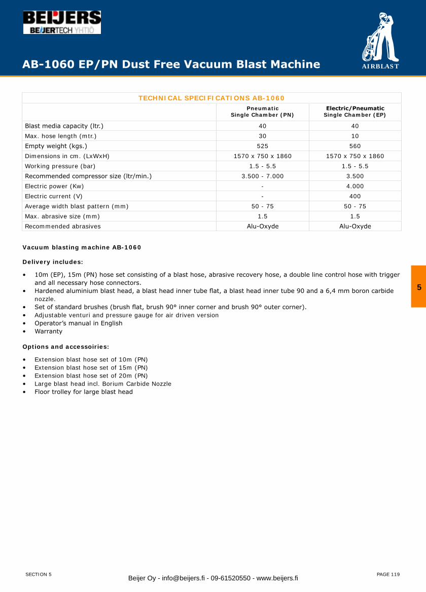
AIRBLAST
PAGE 119
TECHNICAL SPECIFICATIONS AB-1060Pneumatic
Single Chamber (PN)Electric/Pneumatic
Single Chamber (EP)
Blast media capacity (ltr.) 40 40Max. hose length (mtr.) 30 10Empty weight (kgs.) 525 560Dimensions in cm. (LxWxH) 1570 x 750 x 1860 1570 x 750 x 1860Working pressure (bar) 1.5 - 5.5 1.5 - 5.5Recommended compressor size (ltr/min.) 3.500 - 7.000 3.500Electric power (Kw) - 4.000Electric current (V) - 400Average width blast pattern (mm) 50 - 75 50 - 75Max. abrasive size (mm) 1.5 1.5Recommended abrasives Alu-Oxyde Alu-Oxyde
Vacuum blasting machine AB-1060
Delivery includes:
10m (EP), 15m (PN) hose set consisting of a blast hose, abrasive recovery hose, a double line control hose with trigger•and all necessary hose connectors.Hardened aluminium blast head, a blast head inner tube flat, a blast head inner tube 90 and a 6,4 mm boron carbide•nozzle.Set of standard brushes (brush flat, brush 90° inner corner and brush 90° outer corner).•Adjustable venturi and pressure gauge for air driven version•Operator’s manual in English•Warranty•
Options and accessoiries:
Extension blast hose set of 10m (PN)•Extension blast hose set of 15m (PN)•Extension blast hose set of 20m (PN)•Large blast head incl. Borium Carbide Nozzle•Floor trolley for large blast head•
AB-1060 EP/PN Dust Free Vacuum Blast Machine
5
SECTION 5 Beijer Oy - [email protected] - 09-61520550 - www.beijers.fi

AIRBLAST
PAGE 120
The AB-1070 vacuum blast machine is an environmentally friendly dust free blasting solution which is easy to use, versatile and powerful. The use of steel abrasive provides cost effective, efficient and powerful blasting as well as close control of the surface preparation. Easily inter-changeable blast head fittings allow a variety of surfaces to be blasted including: flat, inside & outside corners, small & large diameter pipes etc. Additional accessories are available for specific applications such as to blast large horizontal surfaces or the edges of steel plates. As the process is safe and dust free other production processes can be carried out close to the blasting operation.
AB-1070 EP/PN Dust Free Vacuum Blast Machine
Surface Abrasivetype
Abrasivesize
Obtained surface quality
Average productioncapacity per hour
Steel: millscale, coatings and or corrosion
Alu-oxydeChilled ironSteel grit
0.8-1.2 mm.G17 / G24
SA 2½ (SP10) 4 - 9 m2
Steel: heavycorrosion
Alu-oxydeChilled ironSteel grit
0.8-1.2 mm. G17 / G24
SA 2½ (SP10) 3 - 8 m2
Steel: blasted with shot primer
Alu-oxydeChilled ironSteel grit
0.8-1.2 mm. G17 / G24
SA 2½ (SP10) 5 - 9 m2
Steel: Chlorinated rubber coating
Alu-oxydeChilled ironSteel grit
0.8-1.2 mm. G17 / G24
SA 2½ (SP10) 1.5 - 5 m2
Weld seams: steel Alu-oxydeChilled ironSteel grit
0.8-1.2 mm. G17 / G24
SA 2½ (SP10) 80 - 120 mtr/hr.(50 mm. width)
*) All mentioned values are averages and may vary due to surface conditions, abrasive quality, machine use and experiences of the operator.
Features“Stand alone” unit includes automatic dust extraction and abra-• sive recycling systemQuickly interchangeable blast head fittings to blast different • surface shapesFully pneumatic• Allows blasting from low to high pressure (1 – 8 bar)• Maximum hose length of 35 meters• Can be incorporated into an automatic online blasting process•
BenefitsTotally dust free environmentally friendly blasting• Other job site operations can be conducted close to the blasting area• Zero dust contamination on the job site• Many common shapes can be blasted with ease• Low operation cost due to the use of steel abrasive• Flexible and versatile•
SECTION 5Beijer Oy - [email protected] - 09-61520550 - www.beijers.fi

AIRBLAST
PAGE 121
TECHNICAL SPECIFICATIONS AB-1070Pneumatic
Single Chamber (PN)Electric/Pneumatic
Single Chamber (EP)
Blast media capacity (ltr.) 40 40Max. hose length (mtr.) 45-60 15Empty weight (kgs.) 525 590Dimensions in cm. (WxLxH) 1570 x 750 x 1860 1570 x 750 x 1860Max. working pressure (bar) 8 8Electric power (Kw) 9.200Electric current (V) 400Recommended compressor size (ltr/min.) 3.500 - 10.000 3.500 - 5.000Average width blast pattern (mm) 50 - 75 50 - 75Max. abrasive size (mm) 1.5 1.5
Vacuum blasting machine AB-1070
Delivery includes:
15 m hose set consisting of a blast hose, abrasive recovery hose, a double line control hose with trigger and all necessary • hose connectors.Hardened aluminium blast head, a blast head inner tube flat, a blast head inner tube 90 and a 6,4 mm boron carbide • nozzle.Set of standard brushes (brush flat, brush 90° inner corner and brush 90° outer corner).• Adjustable venturi and pressure gauge for air driven version• Operator’s manual in English• Warranty•
Options and accessoiries:
Extension blast hose set of 10m• Extension blast hose set of 15m• Extension blast hose set of 20m• Large blast head incl. Borium Carbide Nozzle • Floor trolley for large blast head •
AB-1070 EP/PN Dust Free Vacuum Blast Machine
5
SECTION 5 Beijer Oy - [email protected] - 09-61520550 - www.beijers.fi
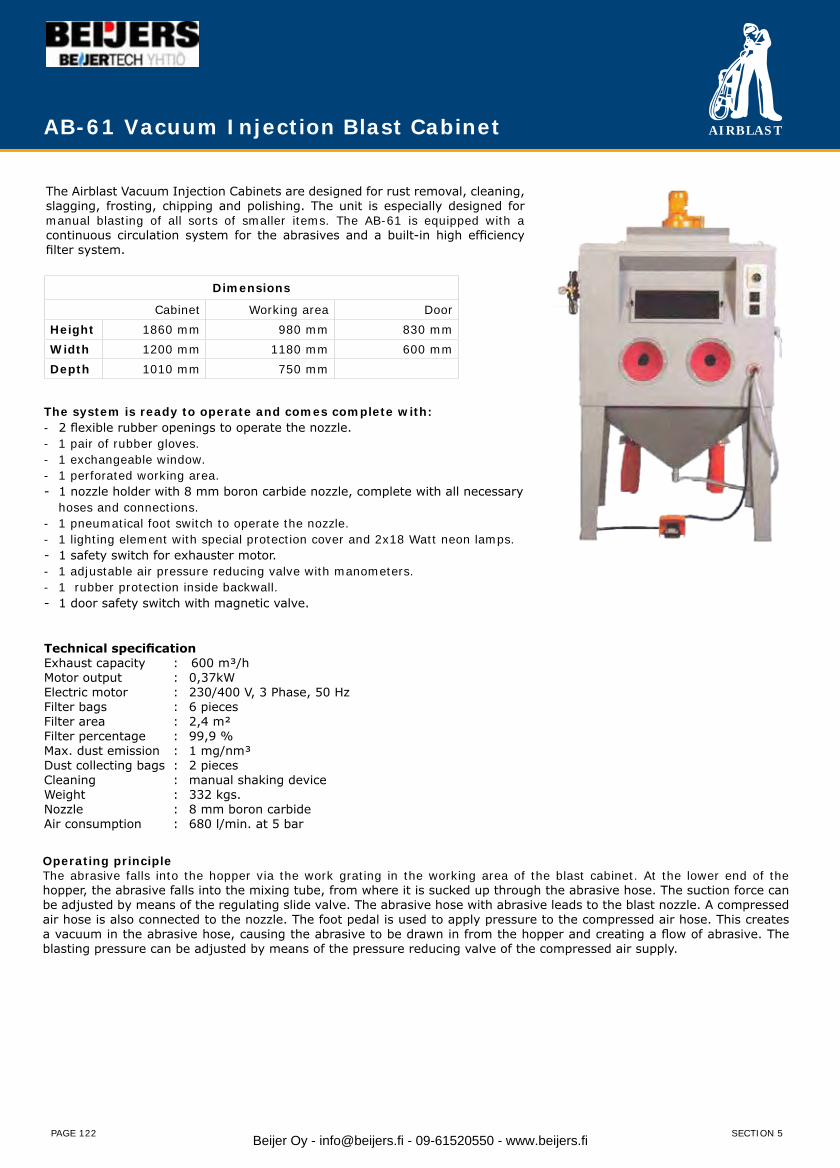
AIRBLAST
PAGE 122
AB-61 Vacuum Injection Blast Cabinet
The Airblast Vacuum Injection Cabinets are designed for rust removal, cleaning, slagging, frosting, chipping and polishing. The unit is especially designed for manual blasting of all sorts of smaller items. The AB-61 is equipped with a continuous circulation system for the abrasives and a built-in high efficiency filter system.
The system is ready to operate and comes complete with:- 2 flexible rubber openings to operate the nozzle.- 1 pair of rubber gloves.- 1 exchangeable window.- 1 perforated working area.- 1 nozzle holder with 8 mm boron carbide nozzle, complete with all necessary hoses and connections.- 1 pneumatical foot switch to operate the nozzle.- 1 lighting element with special protection cover and 2x18 Watt neon lamps.- 1 safety switch for exhauster motor.- 1 adjustable air pressure reducing valve with manometers.- 1 rubber protection inside backwall.- 1 door safety switch with magnetic valve.
Technical specification Exhaust capacity : 600 m³/h Motor output : 0,37kWElectric motor : 230/400 V, 3 Phase, 50 Hz Filter bags : 6 piecesFilter area : 2,4 m² Filter percentage : 99,9 % Max. dust emission : 1 mg/nm³ Dust collecting bags : 2 pieces Cleaning : manual shaking deviceWeight : 332 kgs.Nozzle : 8 mm boron carbideAir consumption : 680 l/min. at 5 bar
Dimensions
Cabinet Working area DoorHeight 1860 mm 980 mm 830 mmWidth 1200 mm 1180 mm 600 mmDepth 1010 mm 750 mm
SECTION 5
Operating principleThe abrasive falls into the hopper via the work grating in the working area of the blast cabinet. At the lower end of the hopper, the abrasive falls into the mixing tube, from where it is sucked up through the abrasive hose. The suction force can be adjusted by means of the regulating slide valve. The abrasive hose with abrasive leads to the blast nozzle. A compressed air hose is also connected to the nozzle. The foot pedal is used to apply pressure to the compressed air hose. This creates a vacuum in the abrasive hose, causing the abrasive to be drawn in from the hopper and creating a flow of abrasive. The blasting pressure can be adjusted by means of the pressure reducing valve of the compressed air supply.
Beijer Oy - [email protected] - 09-61520550 - www.beijers.fi
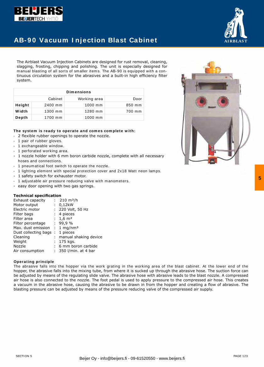
AIRBLAST
PAGE 123
AB-90 Vacuum Injection Blast Cabinet
The Airblast Vacuum Injection Cabinets are designed for rust removal, cleaning, slagging, frosting, chipping and polishing. The unit is especially designed for manual blasting of all sorts of smaller items. The AB-90 is equipped with a con-tinuous circulation system for the abrasives and a built-in high efficiency filter system.
The system is ready to operate and comes complete with:- 2 flexible rubber openings to operate the nozzle.- 1 pair of rubber gloves.- 1 exchangeable window.- 1 perforated working area.- 1 nozzle holder with 6 mm boron carbide nozzle, complete with all necessary hoses and connections.- 1 pneumatical foot switch to operate the nozzle.- 1 lighting element with special protection cover and 2x18 Watt neon lamps.- 1 safety switch for exhauster motor.- 1 adjustable air pressure reducing valve with manometers.- easy door opening with two gas springs.
Technical specification Exhaust capacity : 210 m³/h Motor output : 0,12kWElectric motor : 220 Volt, 50 Hz Filter bags : 4 piecesFilter area : 1,6 m² Filter percentage : 99,9 % Max. dust emission : 1 mg/nm³ Dust collecting bags : 1 pieces Cleaning : manual shaking deviceWeight : 175 kgs.Nozzle : 6 mm boron carbideAir consumption : 350 l/min. at 4 bar
Dimensions
Cabinet Working area DoorHeight 2400 mm 1000 mm 850 mmWidth 1300 mm 1280 mm 700 mmDepth 1700 mm 1000 mm
5
SECTION 5
Operating principleThe abrasive falls into the hopper via the work grating in the working area of the blast cabinet. At the lower end of the hopper, the abrasive falls into the mixing tube, from where it is sucked up through the abrasive hose. The suction force can be adjusted by means of the regulating slide valve. The abrasive hose with abrasive leads to the blast nozzle. A compressed air hose is also connected to the nozzle. The foot pedal is used to apply pressure to the compressed air hose. This creates a vacuum in the abrasive hose, causing the abrasive to be drawn in from the hopper and creating a flow of abrasive. The blasting pressure can be adjusted by means of the pressure reducing valve of the compressed air supply.
Beijer Oy - [email protected] - 09-61520550 - www.beijers.fi
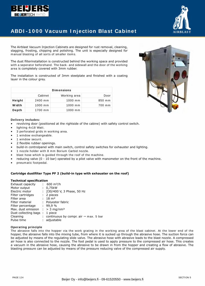
AIRBLAST
PAGE 124
The Airblast Vacuum Injection Cabinets are designed for rust removal, cleaning, slagging, frosting, chipping and polishing. The unit is especially designed for manual blasting of all sorts of smaller items.
The dust filterinstallation is constructed behind the working space and provided with a seperator beforehand. The back- and sidewall and the door of the working area is completely covered with 3mm rubber.
The installation is constructed of 3mm steelplate and finished with a coating layer in the colour grey.
ABDI-1000 Vacuum Injection Blast Cabinet
Delivery includes:revolving door (positioned at the rightside of the cabine) with safety control switch.• lighting 4x18 Watt.• 3 perforated grids in working area.• 1 window exchangeable.• 1 window securit.• 2 flexible rubber openings.• build-in controlpanel with main switch, control safety switches for exhauster and lighting.• 1 nozzle holder with 8 mm Borium Carbid nozzle.• blast hose which is guided through the roof of the machine.• reducing valve (0 - 10 bar) operated by a pilot valve with manometer on the front of the machine.• pneumatic footpedal.•
Cartridge dustfilter Type PF 2 (build-in type with exhauster on the roof)
Technical specification Exhaust capacity : 600 m³/h Motor output : 0,75kWElectric motor : 230/400 V, 3 Phase, 50 Hz Filter cartridges : 2 piecesFilter area : 18 m² Filter material : Polyester fabric Filter percentage : 99,9 % Max. dust emission : > 3 mg/nm³ Dust collecting bags : 1 piece Cleaning : continuous by compr. air max. 5 barPulse time : adjustable
Operating principleThe abrasive falls into the hopper via the work grating in the working area of the blast cabinet. At the lower end of the hopper, the abrasive falls into the mixing tube, from where it is sucked up through the abrasive hose. The suction force can be adjusted by means of the regulating slide valve. The abrasive hose with abrasive leads to the blast nozzle. A compressed air hose is also connected to the nozzle. The foot pedal is used to apply pressure to the compressed air hose. This creates a vacuum in the abrasive hose, causing the abrasive to be drawn in from the hopper and creating a flow of abrasive. The blasting pressure can be adjusted by means of the pressure reducing valve of the compressed air supply.
Dimensions
Cabinet Working area DoorHeight 2400 mm 1000 mm 850 mmWidth 1000 mm 1000 mm 700 mmDepth 1700 mm 1000 mm
SECTION 5Beijer Oy - [email protected] - 09-61520550 - www.beijers.fi
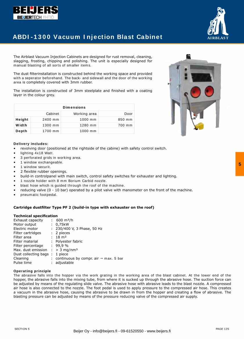
AIRBLAST
PAGE 125
ABDI-1300 Vacuum Injection Blast Cabinet
The Airblast Vacuum Injection Cabinets are designed for rust removal, cleaning, slagging, frosting, chipping and polishing. The unit is especially designed for manual blasting of all sorts of smaller items.
The dust filterinstallation is constructed behind the working space and provided with a seperator beforehand. The back- and sidewall and the door of the working area is completely covered with 3mm rubber.
The installation is constructed of 3mm steelplate and finished with a coating layer in the colour grey.
Delivery includes:revolving door (positioned at the rightside of the cabine) with safety control switch.• lighting 4x18 Watt.• 3 perforated grids in working area.• 1 window exchangeable.• 1 window securit.• 2 flexible rubber openings.• build-in controlpanel with main switch, control safety switches for exhauster and lighting.• 1 nozzle holder with 8 mm Borium Carbid nozzle.• blast hose which is guided through the roof of the machine.• reducing valve (0 - 10 bar) operated by a pilot valve with manometer on the front of the machine.• pneumatic footpedal.•
Cartridge dustfilter Type PF 2 (build-in type with exhauster on the roof)
Technical specification Exhaust capacity : 600 m³/h Motor output : 0,75kWElectric motor : 230/400 V, 3 Phase, 50 Hz Filter cartridges : 2 piecesFilter area : 18 m² Filter material : Polyester fabric Filter percentage : 99,9 % Max. dust emission : > 3 mg/nm³ Dust collecting bags : 1 piece Cleaning : continuous by compr. air max. 5 barPulse time : adjustable
Operating principleThe abrasive falls into the hopper via the work grating in the working area of the blast cabinet. At the lower end of the hopper, the abrasive falls into the mixing tube, from where it is sucked up through the abrasive hose. The suction force can be adjusted by means of the regulating slide valve. The abrasive hose with abrasive leads to the blast nozzle. A compressed air hose is also connected to the nozzle. The foot pedal is used to apply pressure to the compressed air hose. This creates a vacuum in the abrasive hose, causing the abrasive to be drawn in from the hopper and creating a flow of abrasive. The blasting pressure can be adjusted by means of the pressure reducing valve of the compressed air supply.
Dimensions
Cabinet Working area DoorHeight 2400 mm 1000 mm 850 mmWidth 1300 mm 1280 mm 700 mmDepth 1700 mm 1000 mm
5
SECTION 5 Beijer Oy - [email protected] - 09-61520550 - www.beijers.fi
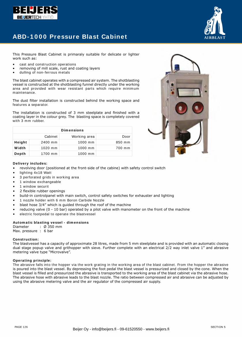
AIRBLAST
PAGE 126
ABD-1000 Pressure Blast Cabinet
This Pressure Blast Cabinet is primaraly suitable for delicate or lighter work such as:
cast and construction operations• removing of mill scale, rust and coating layers• dulling of non-ferrous metals•
The blast cabinet operates with a compressed air system. The shotblasting vessel is constructed at the shotblasting funnel directly under the working area and provided with wear resistant parts which require minimum maintenance.
The dust filter installation is constructed behind the working space and features a separator.
The installation is constructed of 3 mm steelplate and finished with a coating layer in the colour grey. The blasting space is completely covered with 3 mm rubber.
Delivery includes:revolving door (positioned at the front-side of the cabine) with safety control switch• lighting 4x18 Watt• 3 perforated grids in working area• 1 window exchangeable• 1 window securit• 2 flexible rubber openings• build-in controlpanel with main switch, control safety switches for exhauster and lighting• 1 nozzle holder with 6 mm Boron Carbide Nozzle• blast hose 3/4” which is guided through the roof of the machine• reducing valve (0 - 10 bar) operated by a pilot valve with manometer on the front of the machine• electric footpedal to operate the blastvessel•
Automatic blasting vessel - dimensionsDiameter : Ø 350 mmMax. pressure : 6 bar
Construction:The blastvessel has a capacity of approximate 28 litres, made from 5 mm steelplate and is provided with an automatic closing dual stage popup valve and grithopper with sieve. Further complete with an electrical 2/2 way inlet valve 1” and abrasive metering valve type “Microvalve”.
Operating principle:The abrasive falls into the hopper via the work grating in the working area of the blast cabinet. From the hopper the abrasive is poured into the blast vessel. By depressing the foot pedal the blast vessel is pressurized and closed by the cone. When the blast vessel is filled and pressurized the abrasive is transported to the working area of the blast cabinet via the abrasive hose. The abrasive hose with abrasive leads to the blast nozzle. The ratio between compressed air and abrasive can be adjusted by using the abrasive metering valve and the air regulator of the compressed air supply.
Dimensions
Cabinet Working area DoorHeight 2400 mm 1000 mm 850 mmWidth 1020 mm 1000 mm 700 mmDepth 1700 mm 1000 mm
SECTION 5Beijer Oy - [email protected] - 09-61520550 - www.beijers.fi

AIRBLAST
PAGE 127
ABD-1250 Pressure Blast Cabinet
The Airblast Pressure Blast Cabinets are designed for manual or automatic shotblasting of all sorts of items. The general jobs done in these cabinets are continuous and power work, like: cast and construction operations, the removing of mill scale, rust, coating layers to dull non-ferrous metals.
The execution is according the compressed air system. The shotblasting vessel is constructed directly under the working area and provided with wear resistant parts which need little maintenance. The dust filter installation is constructed behind the working space, has a special deflector plate to separate the dust from the airflow. The two cartridges filters with automatic pulsing system remove the finest dust.
The back-wall of the working area space and side door is completely covered with 3mm rubber. The installation is constructed of 3mm steel plate and finished with a coating layer in the colour grey.
The Airblast Pressure Blast Cabinet with pressure blast method offers 3-4 times the production and impact of the suction/induction blast method. The high production method should be considered when there is a large area to be blasted, or where heavy rust, multiple layers of paint, or heavy oxides and scale must be removed.
Delivery includes:swing doors (positioned at the left- and right side of the cabinet) with safety controller• lighting 4x18 Watt• 3 perforated grids in working area• 1 window exchangeable• 1 window securit• 2 flexible rubber openings• build-in controlpanel with main switch, control safety switches for exhauster and lighting• 1 nozzle holder with 6 mm Boron Carbide Nozzle• blast hose 1”• reducing valve (0 - 10 bar) operated by a pilot valve with manometer on the front of the machine• pneumatic footpedal to operate the blastvessel•
Automatic blasting vessel - dimensions:Diameter : Ø 350 mmMax. pressure : 6 bar
Construction:The blastvessel has a capacity of approximate 70 litres, made from 5 mm steelplate and is provided with an automatic closing dual stage popup valve and grithopper with sieve. Further complete with an electrical 2/2 way inlet valve 1” and abrasive metering valve type “Microvalve”.
Operating principle:The abrasive falls into the hopper via the work grating in the working area of the blast cabinet. From the hopper the abrasive is poured into the blast vessel. By depressing the foot pedal the blast vessel is pressurized and closed by the cone. When the blast vessel is filled and pressurized the abrasive is transported to the working area of the blast cabinet via the abrasive hose. The abrasive hose with abrasive leads to the blast nozzle. The ratio between compressed air and abrasive can be adjusted by using the abrasive metering valve and the air regulator of the compressed air supply.
Dimensions
Cabinet Working area DoorHeight 2780 mm 1250 mm 900 mmWidth 1250 mm 1230 mm 900 mmDepth 1810 mm 1250 mm
5
SECTION 5 Beijer Oy - [email protected] - 09-61520550 - www.beijers.fi

AIRBLAST
PAGE 128
ABD-1300 Pressure Blast Cabinet
The Airblast Pressure Blast Cabinets are designed for manual or automatic shotblasting of all sorts of items. The general jobs done in these cabinets are continuous and power work, like: cast and construction operations, the removing of mill scale, rust, coating layers to dull non-ferrous metals
The execution is according the compressed air system. The shot-blasting vessel is constructed directly under the shotblasting chamber and provided with wear resistant parts which need little maintenance. The dust filter installation is constructed behind the working space, has a special deflector plate to separate the dust from the airflow. The two catridges filters with automatic pulsing system remove the finest dust.
The back-wall of the working area and side door is completely covered with 3mm rubber. The installation is constructed of 3mm steel plate and finished with a coating layer in the colour grey.
The Airblast Pressure Blast Cabinet with pressure blast method of-fers 3-4 times the production and impact of the suction/induction blast method. The high production method should be considered when there is a large area to be blasted, or where heavy rust, mul-tiple layers of paint, or heavy oxides and scale must be removed.
Delivery includes:revolving door (positioned at the front-side of the cabine) with safety control switch• lighting 4x18 Watt• 3 perforated grids in working area• 1 window exchangeable• 1 window securit• 2 flexible rubber openings• build-in controlpanel with main switch, control safety switches for exhauster and lighting• 1 nozzle holder with 6 mm Boron Carbide Nozzle• blast hose 3/4” which is guided through the roof of the machine• reducing valve (0 - 10 bar) operated by a pilot valve with manometer on the front of the machine• electric footpedal to operate the blastvessel•
Automatic blasting vessel - dimensions:Diameter : Ø 350 mmMax. pressure : 6 bar
Construction:The blastvessel has a capacity of approximate 28 litres, made from 5 mm steelplate and is provided with an automatic closing dual stage popup valve and grithopper with sieve. Further complete with an electrical 2/2 way inlet valve 1” and abrasive metering valve type “Microvalve”.
Operating principle:The abrasive falls into the hopper via the work grating in the working area of the blast cabinet. From the hopper the abrasive is poured into the blast vessel. By depressing the foot pedal the blast vessel is pressurized and closed by the cone. When the blast vessel is filled and pressurized the abrasive is transported to the working area of the blast cabinet via the abrasive hose. The abrasive hose with abrasive leads to the blast nozzle. The ratio between compressed air and abrasive can be adjusted by using the abrasive metering valve and the air regulator of the compressed air supply.
Dimensions
Cabinet Working area DoorHeight 2400 mm 1000 mm 850 mmWidth 1300 mm 1280 mm 700 mmDepth 1700 mm 1000 mm
SECTION 5Beijer Oy - [email protected] - 09-61520550 - www.beijers.fi
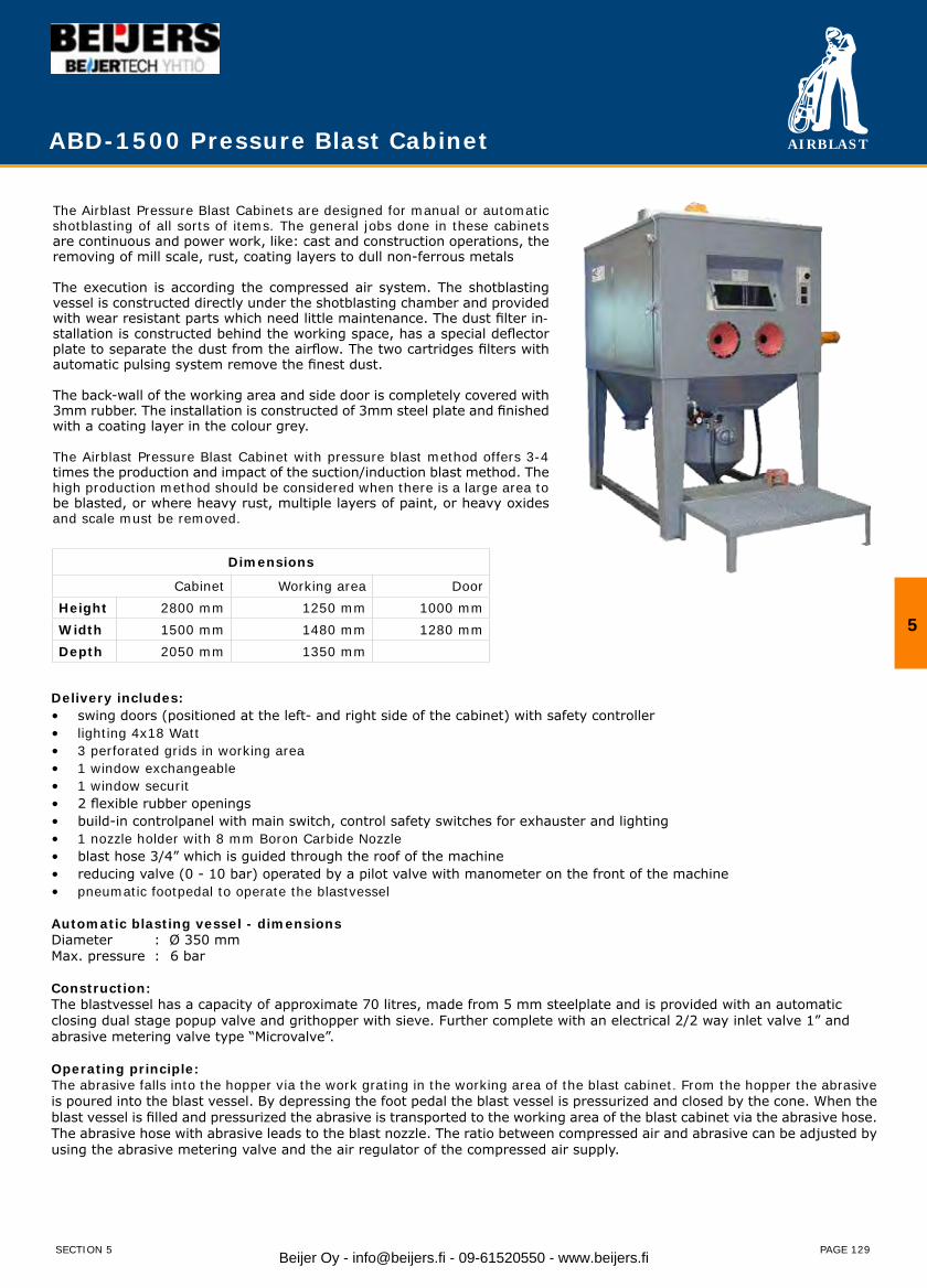
AIRBLAST
PAGE 129
ABD-1500 Pressure Blast Cabinet
The Airblast Pressure Blast Cabinets are designed for manual or automatic shotblasting of all sorts of items. The general jobs done in these cabinets are continuous and power work, like: cast and construction operations, the removing of mill scale, rust, coating layers to dull non-ferrous metals
The execution is according the compressed air system. The shotblasting vessel is constructed directly under the shotblasting chamber and provided with wear resistant parts which need little maintenance. The dust filter in-stallation is constructed behind the working space, has a special deflector plate to separate the dust from the airflow. The two cartridges filters with automatic pulsing system remove the finest dust.
The back-wall of the working area and side door is completely covered with 3mm rubber. The installation is constructed of 3mm steel plate and finished with a coating layer in the colour grey.
The Airblast Pressure Blast Cabinet with pressure blast method offers 3-4 times the production and impact of the suction/induction blast method. The high production method should be considered when there is a large area to be blasted, or where heavy rust, multiple layers of paint, or heavy oxides and scale must be removed.
Delivery includes:swing doors (positioned at the left- and right side of the cabinet) with safety controller• lighting 4x18 Watt• 3 perforated grids in working area• 1 window exchangeable• 1 window securit• 2 flexible rubber openings• build-in controlpanel with main switch, control safety switches for exhauster and lighting• 1 nozzle holder with 8 mm Boron Carbide Nozzle• blast hose 3/4” which is guided through the roof of the machine• reducing valve (0 - 10 bar) operated by a pilot valve with manometer on the front of the machine• pneumatic footpedal to operate the blastvessel•
Automatic blasting vessel - dimensionsDiameter : Ø 350 mmMax. pressure : 6 bar
Construction:The blastvessel has a capacity of approximate 70 litres, made from 5 mm steelplate and is provided with an automatic closing dual stage popup valve and grithopper with sieve. Further complete with an electrical 2/2 way inlet valve 1” and abrasive metering valve type “Microvalve”.
Operating principle:The abrasive falls into the hopper via the work grating in the working area of the blast cabinet. From the hopper the abrasive is poured into the blast vessel. By depressing the foot pedal the blast vessel is pressurized and closed by the cone. When the blast vessel is filled and pressurized the abrasive is transported to the working area of the blast cabinet via the abrasive hose. The abrasive hose with abrasive leads to the blast nozzle. The ratio between compressed air and abrasive can be adjusted by using the abrasive metering valve and the air regulator of the compressed air supply.
Dimensions
Cabinet Working area DoorHeight 2800 mm 1250 mm 1000 mmWidth 1500 mm 1480 mm 1280 mmDepth 2050 mm 1350 mm
5
SECTION 5 Beijer Oy - [email protected] - 09-61520550 - www.beijers.fi
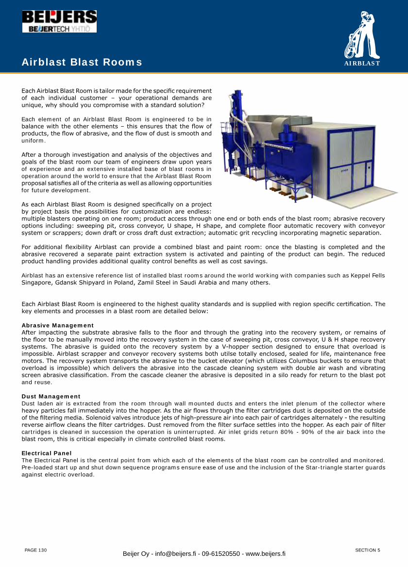
AIRBLAST
PAGE 130
Each Airblast Blast Room is tailor made for the specific requirement of each individual customer – your operational demands are unique, why should you compromise with a standard solution?
Each element of an Airblast Blast Room is engineered to be in balance with the other elements – this ensures that the flow of products, the flow of abrasive, and the flow of dust is smooth and uniform.
After a thorough investigation and analysis of the objectives and goals of the blast room our team of engineers draw upon years of experience and an extensive installed base of blast rooms in operation around the world to ensure that the Airblast Blast Room proposal satisfies all of the criteria as well as allowing opportunities for future development.
As each Airblast Blast Room is designed specifically on a project by project basis the possibilities for customization are endless: multiple blasters operating on one room; product access through one end or both ends of the blast room; abrasive recovery options including: sweeping pit, cross conveyor, U shape, H shape, and complete floor automatic recovery with conveyor system or scrappers; down draft or cross draft dust extraction; automatic grit recycling incorporating magnetic separation.
For additional flexibility Airblast can provide a combined blast and paint room: once the blasting is completed and the abrasive recovered a separate paint extraction system is activated and painting of the product can begin. The reduced product handling provides additional quality control benefits as well as cost savings.
Airblast has an extensive reference list of installed blast rooms around the world working with companies such as Keppel Fells Singapore, Gdansk Shipyard in Poland, Zamil Steel in Saudi Arabia and many others.
Each Airblast Blast Room is engineered to the highest quality standards and is supplied with region specific certification. The key elements and processes in a blast room are detailed below:
Abrasive ManagementAfter impacting the substrate abrasive falls to the floor and through the grating into the recovery system, or remains of the floor to be manually moved into the recovery system in the case of sweeping pit, cross conveyor, U & H shape recovery systems. The abrasive is guided onto the recovery system by a V-hopper section designed to ensure that overload is impossible. Airblast scrapper and conveyor recovery systems both utilse totally enclosed, sealed for life, maintenance free motors. The recovery system transports the abrasive to the bucket elevator (which utilizes Columbus buckets to ensure that overload is impossible) which delivers the abrasive into the cascade cleaning system with double air wash and vibrating screen abrasive classification. From the cascade cleaner the abrasive is deposited in a silo ready for return to the blast pot and reuse.
Dust ManagementDust laden air is extracted from the room through wall mounted ducts and enters the inlet plenum of the collector where heavy particles fall immediately into the hopper. As the air flows through the filter cartridges dust is deposited on the outside of the filtering media. Solenoid valves introduce jets of high-pressure air into each pair of cartridges alternately - the resulting reverse airflow cleans the filter cartridges. Dust removed from the filter surface settles into the hopper. As each pair of filter cartridges is cleaned in succession the operation is uninterrupted. Air inlet grids return 80% - 90% of the air back into the blast room, this is critical especially in climate controlled blast rooms.
Electrical PanelThe Electrical Panel is the central point from which each of the elements of the blast room can be controlled and monitored. Pre-loaded start up and shut down sequence programs ensure ease of use and the inclusion of the Star-triangle starter guards against electric overload.
Airblast Blast Rooms
SECTION 5Beijer Oy - [email protected] - 09-61520550 - www.beijers.fi
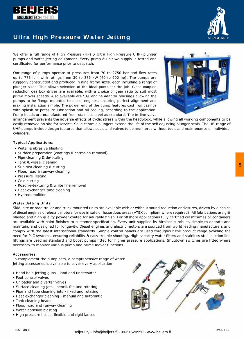
AIRBLAST
PAGE 131
Ultra High Pressure Water Jetting
We offer a full range of High Pressure (HP) & Ultra High Pressure(UHP) plunger pumps and water jetting equipment. Every pump & unit we supply is tested and certificated for performance prior to despatch.
Our range of pumps operate at pressures from 70 to 2750 bar and flow rates up to 773 lpm with ratings from 30 to 375 kW (40 to 500 hp). The pumps are ruggedly constructed and produced in nine frame sizes, each including a range of plunger sizes. This allows selection of the ideal pump for the job. Close-coupled reduction gearbox drives are available, with a choice of gear ratio to suit most prime mover speeds. Also available are SAE engine adaptor housings allowing the pumps to be flange mounted to diesel engines, ensuring perfect alignment and making installation simple. The power end of the pump features cast iron casings with splash or pressure lubrication and oil cooling, according to the application. Pump heads are manufactured from stainless steel as standard. The in-line valve arrangement prevents the adverse effects of cyclic stress within the headblock, while allowing all working components to be easily removed on site for service. Solid ceramic plungers extend the life of the self adjusting plunger seals. The UB-range of UHP pumps include design features that allows seals and valves to be monitored without tools and maintenance on individual cylinders.
Typical Applications:• Water & abrasive blasting• Surface preparation (coatings & corrosion removal)• Pipe cleaning & de-scaling• Tank & vessel cleaning• Sub-sea cleaning & cutting• Floor, road & runway cleaning• Pressure Testing• Cold cutting• Road re-texturing & white line removal• Heat exchanger tube cleaning• Hydrodemolition
Water Jetting Units Skid, site or road trailer and truck mounted units are available with or without sound reduction enclosures, driven by a choice of diesel engines or electric motors for use in safe or hazardous areas (ATEX compliant where required). All fabrications are grit blasted and high quality powder coated for adurable finish. For offshore applications fully certified crashframes or containers are available with paint finishes to customer specification. Every unit supplied by Airblast is robust, simple to operate and maintain, and designed for longevity. Diesel engines and electric motors are sourced from world leading manufacturers and comply with the latest international standards. Simple control panels are used throughout the product range avoiding the need for PLC systems, ensuring reliability & easy trouble shooting. High capacity water filters and stainless steel suction line fittings are used as standard and boost pumps fitted for higher pressure applications. Shutdown switches are fitted where necessary to monitor various pump and prime mover functions.
AccessoriesTo complement the pump sets, a comprehensive range of waterjetting accessories is available to cover every application:
• Hand held jetting guns - land and underwater• Foot control valves• Unloader and diverter valves• Surface cleaning jets - pencil, fan and rotating• Pipe and tube cleaning jets - fixed and rotating• Heat exchanger cleaning - manual and automatic• Tank cleaning heads• Floor, road and runway cleaning• Water abrasive blasting• High pressure hoses, flexible and rigid lances
5
SECTION 5 Beijer Oy - [email protected] - 09-61520550 - www.beijers.fi
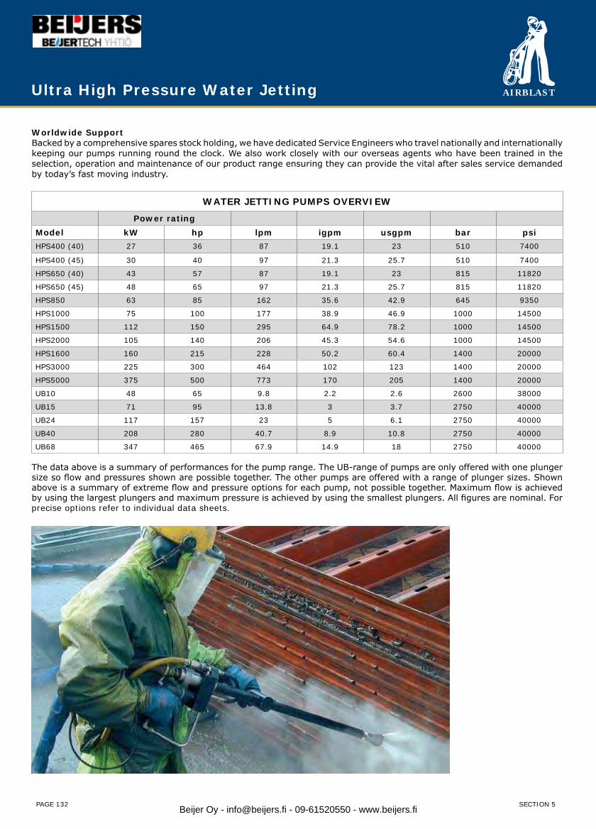
AIRBLAST
PAGE 132
Worldwide SupportBacked by a comprehensive spares stock holding, we have dedicated Service Engineers who travel nationally and internationally keeping our pumps running round the clock. We also work closely with our overseas agents who have been trained in the selection, operation and maintenance of our product range ensuring they can provide the vital after sales service demanded by today’s fast moving industry.
WATER JETTING PUMPS OVERVIEW
Power ratingModel kW hp lpm igpm usgpm bar psiHPS400 (40) 27 36 87 19.1 23 510 7400
HPS400 (45) 30 40 97 21.3 25.7 510 7400
HPS650 (40) 43 57 87 19.1 23 815 11820
HPS650 (45) 48 65 97 21.3 25.7 815 11820
HPS850 63 85 162 35.6 42.9 645 9350
HPS1000 75 100 177 38.9 46.9 1000 14500
HPS1500 112 150 295 64.9 78.2 1000 14500
HPS2000 105 140 206 45.3 54.6 1000 14500
HPS1600 160 215 228 50.2 60.4 1400 20000
HPS3000 225 300 464 102 123 1400 20000
HPS5000 375 500 773 170 205 1400 20000
UB10 48 65 9.8 2.2 2.6 2600 38000
UB15 71 95 13.8 3 3.7 2750 40000
UB24 117 157 23 5 6.1 2750 40000
UB40 208 280 40.7 8.9 10.8 2750 40000
UB68 347 465 67.9 14.9 18 2750 40000
The data above is a summary of performances for the pump range. The UB-range of pumps are only offered with one plunger size so flow and pressures shown are possible together. The other pumps are offered with a range of plunger sizes. Shown above is a summary of extreme flow and pressure options for each pump, not possible together. Maximum flow is achieved by using the largest plungers and maximum pressure is achieved by using the smallest plungers. All figures are nominal. For precise options refer to individual data sheets.
Ultra High Pressure Water Jetting
SECTION 5Beijer Oy - [email protected] - 09-61520550 - www.beijers.fi
AIRBLAST
PAGE 145
Section 7 - Material Handling
Product PageAIRVAC Portable vacuum recovery system 146AIRVAC with cyclone separator 147ABVAC Mobile vacuum recovery system 148AB710 Heavy duty recovery & cleaning system 149ABVR Mobile vacuum recovery system 150RC-50-20 Grit recycling system 151RC-50-150 Grit recycling system 152RC-80-160 Grit recycling system 154AB2030 Vacuum cleaner - pneumatic 156AB2030 Vacuum cleaner - electric 156AB2050 Vacuum cleaner - pneumatic 157AB2050 Vacuum cleaner - electric 157
7
SECTION 7 Beijer Oy - [email protected] - 09-61520550 - www.beijers.fi
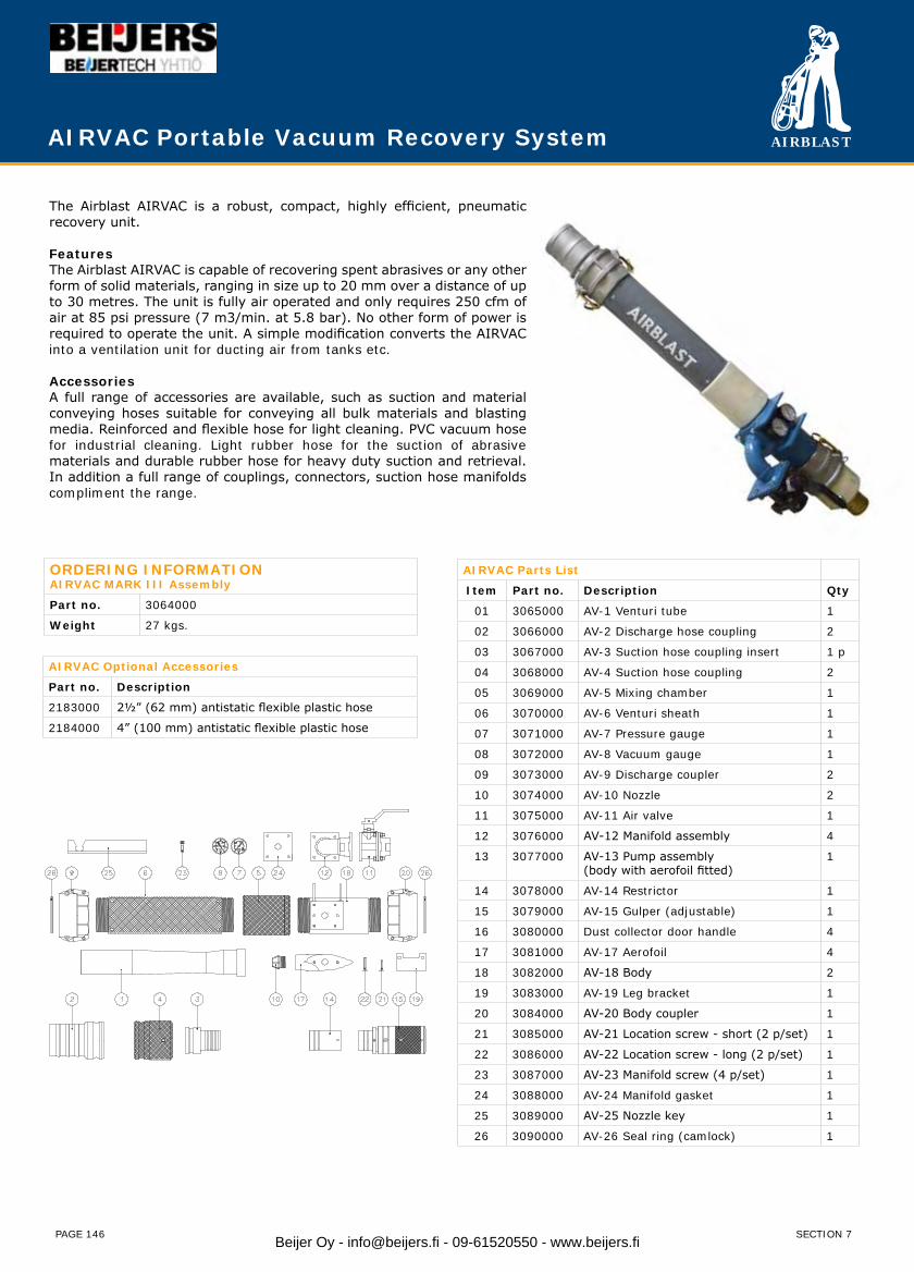
AIRBLAST
PAGE 146
AIRVAC Portable Vacuum Recovery System
ORDERING INFORMATIONAIRVAC MARK III Assembly
Part no. 3064000
Weight 27 kgs.
AIRVAC Optional Accessories
Part no. Description
2183000 2½” (62 mm) antistatic flexible plastic hose
2184000 4” (100 mm) antistatic flexible plastic hose
AIRVAC Parts List
Item Part no. Description Qty
01 3065000 AV-1 Venturi tube 1
02 3066000 AV-2 Discharge hose coupling 2
03 3067000 AV-3 Suction hose coupling insert 1 p
04 3068000 AV-4 Suction hose coupling 2
05 3069000 AV-5 Mixing chamber 1
06 3070000 AV-6 Venturi sheath 1
07 3071000 AV-7 Pressure gauge 1
08 3072000 AV-8 Vacuum gauge 1
09 3073000 AV-9 Discharge coupler 2
10 3074000 AV-10 Nozzle 2
11 3075000 AV-11 Air valve 1
12 3076000 AV-12 Manifold assembly 4
13 3077000 AV-13 Pump assembly(body with aerofoil fitted)
1
14 3078000 AV-14 Restrictor 1
15 3079000 AV-15 Gulper (adjustable) 1
16 3080000 Dust collector door handle 4
17 3081000 AV-17 Aerofoil 4
18 3082000 AV-18 Body 2
19 3083000 AV-19 Leg bracket 1
20 3084000 AV-20 Body coupler 1
21 3085000 AV-21 Location screw - short (2 p/set) 1
22 3086000 AV-22 Location screw - long (2 p/set) 1
23 3087000 AV-23 Manifold screw (4 p/set) 1
24 3088000 AV-24 Manifold gasket 1
25 3089000 AV-25 Nozzle key 1
26 3090000 AV-26 Seal ring (camlock) 1
The Airblast AIRVAC is a robust, compact, highly efficient, pneumatic recovery unit.
FeaturesThe Airblast AIRVAC is capable of recovering spent abrasives or any other form of solid materials, ranging in size up to 20 mm over a distance of up to 30 metres. The unit is fully air operated and only requires 250 cfm of air at 85 psi pressure (7 m3/min. at 5.8 bar). No other form of power is required to operate the unit. A simple modification converts the AIRVAC into a ventilation unit for ducting air from tanks etc.
AccessoriesA full range of accessories are available, such as suction and material conveying hoses suitable for conveying all bulk materials and blasting media. Reinforced and flexible hose for light cleaning. PVC vacuum hose for industrial cleaning. Light rubber hose for the suction of abrasive materials and durable rubber hose for heavy duty suction and retrieval. In addition a full range of couplings, connectors, suction hose manifolds compliment the range.
SECTION 7Beijer Oy - [email protected] - 09-61520550 - www.beijers.fi
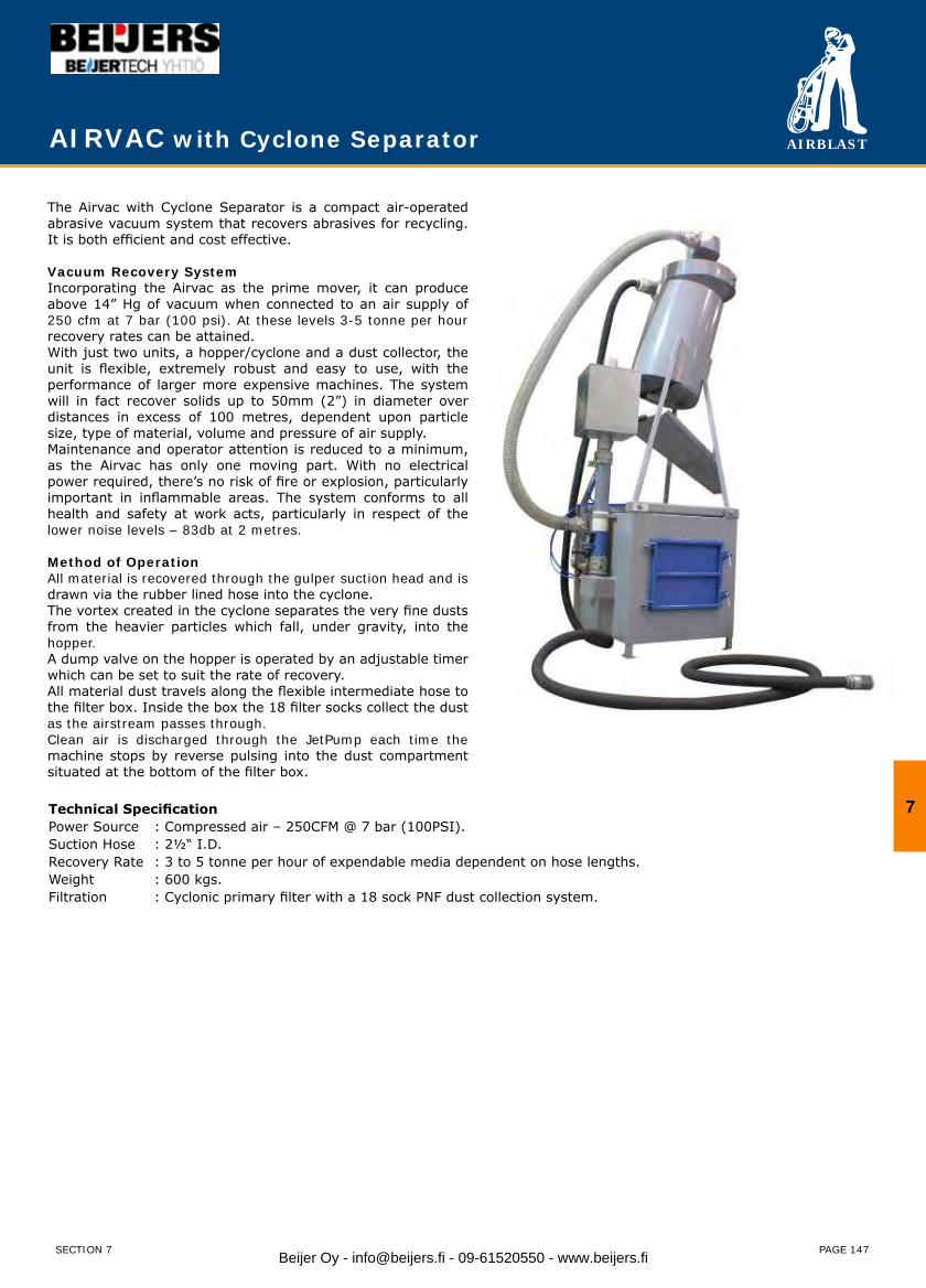
AIRBLAST
PAGE 147
AIRVAC with Cyclone Separator
The Airvac with Cyclone Separator is a compact air-operated abrasive vacuum system that recovers abrasives for recycling. It is both efficient and cost effective.
Vacuum Recovery SystemIncorporating the Airvac as the prime mover, it can produce above 14” Hg of vacuum when connected to an air supply of 250 cfm at 7 bar (100 psi). At these levels 3-5 tonne per hour recovery rates can be attained.With just two units, a hopper/cyclone and a dust collector, the unit is flexible, extremely robust and easy to use, with the performance of larger more expensive machines. The system will in fact recover solids up to 50mm (2”) in diameter over distances in excess of 100 metres, dependent upon particle size, type of material, volume and pressure of air supply.Maintenance and operator attention is reduced to a minimum, as the Airvac has only one moving part. With no electrical power required, there’s no risk of fire or explosion, particularly important in inflammable areas. The system conforms to all health and safety at work acts, particularly in respect of the lower noise levels – 83db at 2 metres.
Method of OperationAll material is recovered through the gulper suction head and is drawn via the rubber lined hose into the cyclone.The vortex created in the cyclone separates the very fine dusts from the heavier particles which fall, under gravity, into the hopper.A dump valve on the hopper is operated by an adjustable timer which can be set to suit the rate of recovery.All material dust travels along the flexible intermediate hose to the filter box. Inside the box the 18 filter socks collect the dust as the airstream passes through.Clean air is discharged through the JetPump each time the machine stops by reverse pulsing into the dust compartment situated at the bottom of the filter box.
Technical SpecificationPower Source : Compressed air – 250CFM @ 7 bar (100PSI).Suction Hose : 2½“ I.D.Recovery Rate : 3 to 5 tonne per hour of expendable media dependent on hose lengths.Weight : 600 kgs.Filtration : Cyclonic primary filter with a 18 sock PNF dust collection system.
7
SECTION 7 Beijer Oy - [email protected] - 09-61520550 - www.beijers.fi

AIRBLAST
PAGE 148
ABVAC Mobile Vacuum Recovery System
ABVAC is an electric-powered suction unit mounted onto a rigid stand equipped with retractable legs. The unit is designed for the collection of anything from dust up to 50mm debris into a big bag and is ideal for both mobile use and for fixed installations. The unit can also be combined with an abrasive storage hopper to allow recovered abrasive to be reused.
The retractable legs make it easy to move around and they allow the discharge outlet height to be adjusted to fit any size of big bag. It’s transportability means that the unit is mostly used as a free-standing suction unit with the connection of a 3” or 4” hose. However, it is also suitable for fixed installations connected to a fixed installed pipe system with multiple suction outlets.
Optimal SolutionAs the unit is designed and equipped with an outlet for connecting a big bag, it can be used without a separate drop out box. The unit requires no compressed air and offers huge airflow per kW. The high suction capacity, together with its flexible discharge system, makes the unit very useful in most grit recovery situations.Due to its flexibility, the ABVAC unit gets access to most areas where cleaning needs to be carried out, increasing media recovery rates usually limited by long runs of hose. The unit is easily manoeuvred using a standard forklift truck or crane.
Why ABVAC• Automatic big bag filling of collected material.• Power alternatives 16.5 & 25kW.• CEE power intake for 32 or 63 A respectively.• Filter system for dry and moist material.• Automatic ATM filter cleaning system, without compressed air.• Easy height adjustment to suit various big bags.• Improved safety and lower labour costs.• Various options of safety filters.
Available with a wide range of flexible hoses, tools and extensions.
Model ABVAC 165 ABVAC 165 Optional Abrasive Silo
Weight, kg (empty) 1130 1130
Var
iou
s si
zes
and
cap
acit
ies
avai
lab
le.
Max Vacuum, mbar 290 400Max. Air Volume m3/h (unloaded) 1100 1100Electrical Motor, kW 12,5 12,5Voltage Frequency, V/Hz 400/50 400/50Filter surface, m2 10 10Noise Level dB(A) (1 m/5 m distancea) 75/70 75/70Dimension dust inlet, dia mm 108 108
SECTION 7Beijer Oy - [email protected] - 09-61520550 - www.beijers.fi
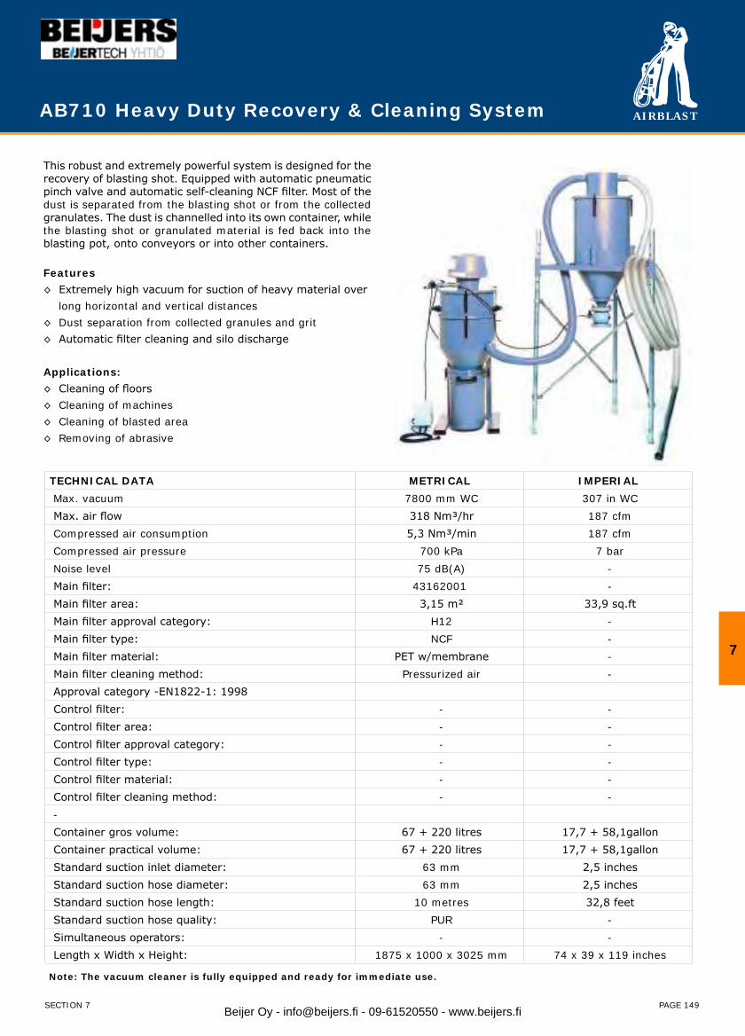
AIRBLAST
PAGE 149
AB710 Heavy Duty Recovery & Cleaning System
This robust and extremely powerful system is designed for the recovery of blasting shot. Equipped with automatic pneumatic pinch valve and automatic self-cleaning NCF filter. Most of the dust is separated from the blasting shot or from the collected granulates. The dust is channelled into its own container, while the blasting shot or granulated material is fed back into the blasting pot, onto conveyors or into other containers. Features◊ Extremely high vacuum for suction of heavy material over long horizontal and vertical distances◊ Dust separation from collected granules and grit◊ Automatic filter cleaning and silo discharge Applications: ◊ Cleaning of floors◊ Cleaning of machines◊ Cleaning of blasted area◊ Removing of abrasive
TECHNICAL DATA METRICAL IMPERIAL Max. vacuum 7800 mm WC 307 in WC Max. air flow 318 Nm³/hr 187 cfm Compressed air consumption 5,3 Nm³/min 187 cfm Compressed air pressure 700 kPa 7 bar Noise level 75 dB(A) - Main filter: 43162001 - Main filter area: 3,15 m² 33,9 sq.ft Main filter approval category: H12 - Main filter type: NCF - Main filter material: PET w/membrane - Main filter cleaning method: Pressurized air - Approval category -EN1822-1: 1998 Control filter: - - Control filter area: - - Control filter approval category: - - Control filter type: - - Control filter material: - - Control filter cleaning method: - - - Container gros volume: 67 + 220 litres 17,7 + 58,1gallon Container practical volume: 67 + 220 litres 17,7 + 58,1gallon Standard suction inlet diameter: 63 mm 2,5 inches Standard suction hose diameter: 63 mm 2,5 inches Standard suction hose length: 10 metres 32,8 feet Standard suction hose quality: PUR - Simultaneous operators: - - Length x Width x Height: 1875 x 1000 x 3025 mm 74 x 39 x 119 inches
Note: The vacuum cleaner is fully equipped and ready for immediate use.
7
SECTION 7 Beijer Oy - [email protected] - 09-61520550 - www.beijers.fi
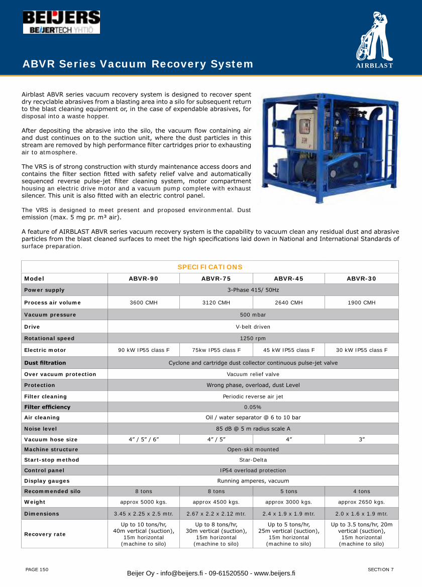
AIRBLAST
PAGE 150
Airblast ABVR series vacuum recovery system is designed to recover spent dry recyclable abrasives from a blasting area into a silo for subsequent return to the blast cleaning equipment or, in the case of expendable abrasives, for disposal into a waste hopper.
After depositing the abrasive into the silo, the vacuum flow containing air and dust continues on to the suction unit, where the dust particles in this stream are removed by high performance filter cartridges prior to exhausting air to atmosphere.
The VRS is of strong construction with sturdy maintenance access doors and contains the filter section fitted with safety relief valve and automatically sequenced reverse pulse-jet filter cleaning system, motor compartment housing an electric drive motor and a vacuum pump complete with exhaust silencer. This unit is also fitted with an electric control panel.
The VRS is designed to meet present and proposed environmental. Dust emission (max. 5 mg pr. m³ air).
A feature of AIRBLAST ABVR series vacuum recovery system is the capability to vacuum clean any residual dust and abrasive particles from the blast cleaned surfaces to meet the high specifications laid down in National and International Standards of surface preparation.
SPECIFICATIONSModel ABVR-90 ABVR-75 ABVR-45 ABVR-30
Power supply 3-Phase 415/ 50Hz
Process air volume 3600 CMH 3120 CMH 2640 CMH 1900 CMH
Vacuum pressure 500 mbar
Drive V-belt driven
Rotational speed 1250 rpm
Electric motor 90 kW IP55 class F 75kw IP55 class F 45 kW IP55 class F 30 kW IP55 class F
Dust filtration Cyclone and cartridge dust collector continuous pulse-jet valve
Over vacuum protection Vacuum relief valve
Protection Wrong phase, overload, dust Level
Filter cleaning Periodic reverse air jet
Filter efficiency 0.05%
Air cleaning Oil / water separator @ 6 to 10 bar
Noise level 85 dB @ 5 m radius scale A
Vacuum hose size 4” / 5” / 6” 4” / 5” 4” 3”
Machine structure Open-skit mounted
Start-stop method Star-Delta
Control panel IP54 overload protection
Display gauges Running amperes, vacuum
Recommended silo 8 tons 8 tons 5 tons 4 tons
Weight approx 5000 kgs. approx 4500 kgs. approx 3000 kgs. approx 2650 kgs.
Dimensions 3.45 x 2.25 x 2.5 mtr. 2.67 x 2.2 x 2.12 mtr. 2.4 x 1.9 x 1.9 mtr. 2.0 x 1.6 x 1.9 mtr.
Recovery rate
Up to 10 tons/hr,40m vertical (suction),
15m horizontal(machine to silo)
Up to 8 tons/hr,30m vertical (suction),
15m horizontal(machine to silo)
Up to 5 tons/hr,25m vertical (suction),
15m horizontal (machine to silo)
Up to 3.5 tons/hr, 20m vertical (suction),15m horizontal
(machine to silo)
ABVR Series Vacuum Recovery System
SECTION 7Beijer Oy - [email protected] - 09-61520550 - www.beijers.fi
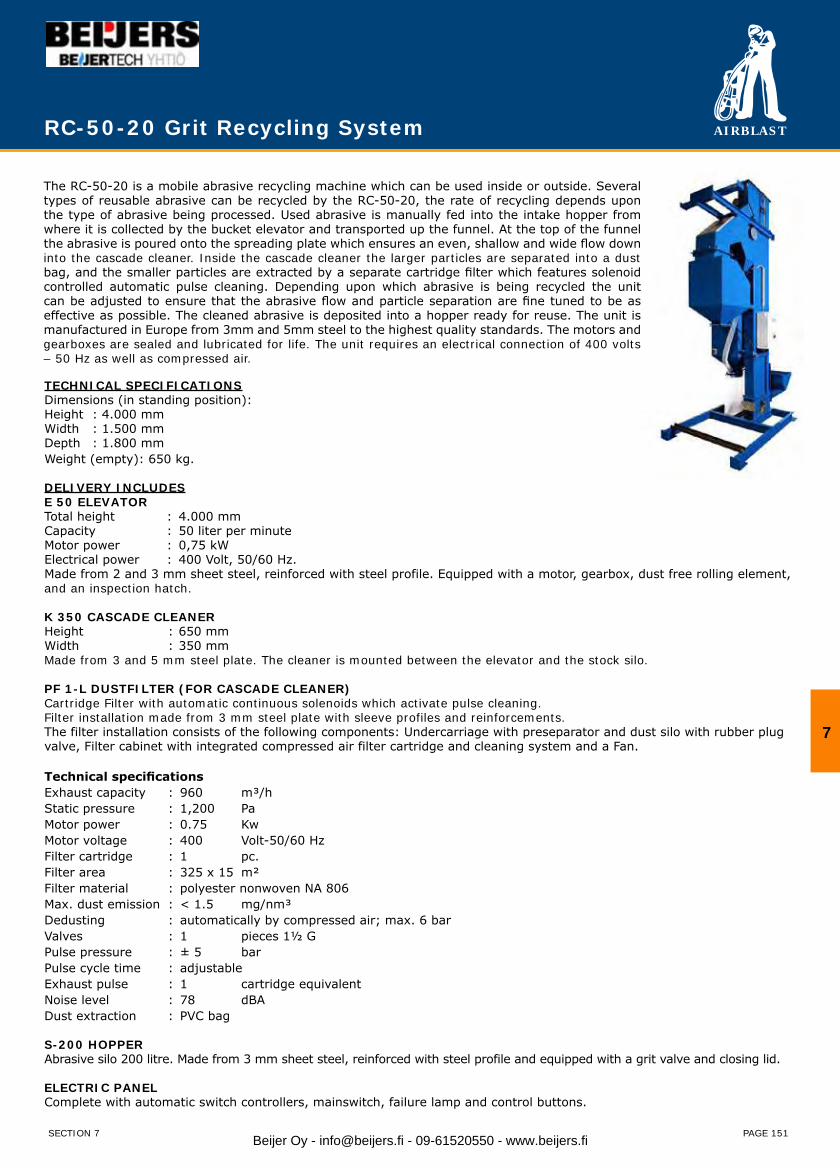
AIRBLAST
PAGE 151
The RC-50-20 is a mobile abrasive recycling machine which can be used inside or outside. Several types of reusable abrasive can be recycled by the RC-50-20, the rate of recycling depends upon the type of abrasive being processed. Used abrasive is manually fed into the intake hopper from where it is collected by the bucket elevator and transported up the funnel. At the top of the funnel the abrasive is poured onto the spreading plate which ensures an even, shallow and wide flow down into the cascade cleaner. Inside the cascade cleaner the larger particles are separated into a dust bag, and the smaller particles are extracted by a separate cartridge filter which features solenoid controlled automatic pulse cleaning. Depending upon which abrasive is being recycled the unit can be adjusted to ensure that the abrasive flow and particle separation are fine tuned to be as effective as possible. The cleaned abrasive is deposited into a hopper ready for reuse. The unit is manufactured in Europe from 3mm and 5mm steel to the highest quality standards. The motors and gearboxes are sealed and lubricated for life. The unit requires an electrical connection of 400 volts – 50 Hz as well as compressed air.
RC-50-20 Grit Recycling System
TECHNICAL SPECIFICATIONSDimensions (in standing position): Height : 4.000 mmWidth : 1.500 mmDepth : 1.800 mmWeight (empty): 650 kg.
DELIVERY INCLUDESE 50 ELEVATORTotal height : 4.000 mmCapacity : 50 liter per minuteMotor power : 0,75 kWElectrical power : 400 Volt, 50/60 Hz.Made from 2 and 3 mm sheet steel, reinforced with steel profile. Equipped with a motor, gearbox, dust free rolling element, and an inspection hatch.
K 350 CASCADE CLEANERHeight : 650 mmWidth : 350 mmMade from 3 and 5 mm steel plate. The cleaner is mounted between the elevator and the stock silo.
PF 1-L DUSTFILTER (FOR CASCADE CLEANER)Cartridge Filter with automatic continuous solenoids which activate pulse cleaning.Filter installation made from 3 mm steel plate with sleeve profiles and reinforcements.The filter installation consists of the following components: Undercarriage with preseparator and dust silo with rubber plug valve, Filter cabinet with integrated compressed air filter cartridge and cleaning system and a Fan.
Technical specificationsExhaust capacity : 960 m³/hStatic pressure : 1,200 PaMotor power : 0.75 KwMotor voltage : 400 Volt-50/60 HzFilter cartridge : 1 pc.Filter area : 325 x 15 m² Filter material : polyester nonwoven NA 806Max. dust emission : < 1.5 mg/nm³ Dedusting : automatically by compressed air; max. 6 barValves : 1 pieces 1½ GPulse pressure : ± 5 barPulse cycle time : adjustable Exhaust pulse : 1 cartridge equivalentNoise level : 78 dBADust extraction : PVC bag
S-200 HOPPERAbrasive silo 200 litre. Made from 3 mm sheet steel, reinforced with steel profile and equipped with a grit valve and closing lid.
ELECTRIC PANELComplete with automatic switch controllers, mainswitch, failure lamp and control buttons.
SECTION 7
7
Beijer Oy - [email protected] - 09-61520550 - www.beijers.fi
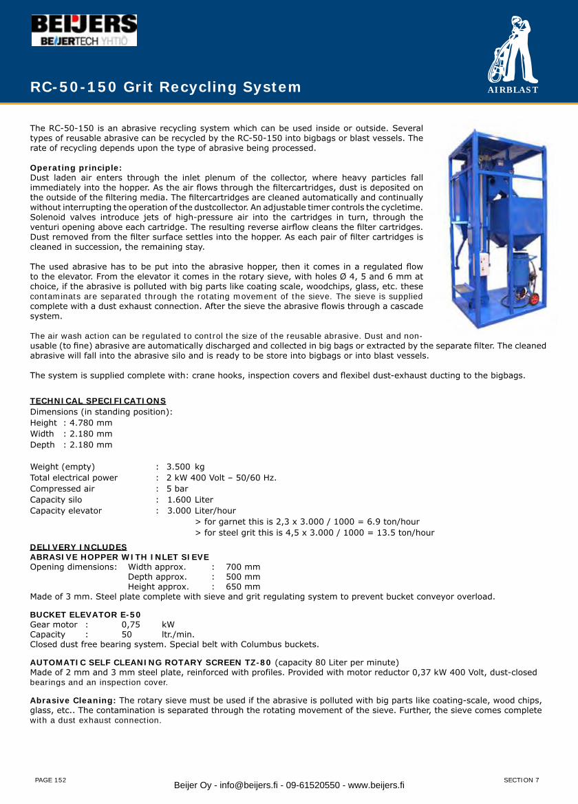
AIRBLAST
PAGE 152
RC-50-150 Grit Recycling System
The RC-50-150 is an abrasive recycling system which can be used inside or outside. Several types of reusable abrasive can be recycled by the RC-50-150 into bigbags or blast vessels. The rate of recycling depends upon the type of abrasive being processed.
Operating principle:Dust laden air enters through the inlet plenum of the collector, where heavy particles fall immediately into the hopper. As the air flows through the filtercartridges, dust is deposited on the outside of the filtering media. The filtercartridges are cleaned automatically and continually without interrupting the operation of the dustcollector. An adjustable timer controls the cycletime. Solenoid valves introduce jets of high-pressure air into the cartridges in turn, through the venturi opening above each cartridge. The resulting reverse airflow cleans the filter cartridges. Dust removed from the filter surface settles into the hopper. As each pair of filter cartridges is cleaned in succession, the remaining stay.
The used abrasive has to be put into the abrasive hopper, then it comes in a regulated flow to the elevator. From the elevator it comes in the rotary sieve, with holes Ø 4, 5 and 6 mm at choice, if the abrasive is polluted with big parts like coating scale, woodchips, glass, etc. these contaminats are separated through the rotating movement of the sieve. The sieve is supplied complete with a dust exhaust connection. After the sieve the abrasive flowis through a cascade system.
The air wash action can be regulated to control the size of the reusable abrasive. Dust and non-usable (to fine) abrasive are automatically discharged and collected in big bags or extracted by the separate filter. The cleaned abrasive will fall into the abrasive silo and is ready to be store into bigbags or into blast vessels.
The system is supplied complete with: crane hooks, inspection covers and flexibel dust-exhaust ducting to the bigbags.
TECHNICAL SPECIFICATIONSDimensions (in standing position): Height : 4.780 mmWidth : 2.180 mmDepth : 2.180 mm
Weight (empty) : 3.500 kgTotal electrical power : 2 kW 400 Volt – 50/60 Hz.Compressed air : 5 barCapacity silo : 1.600 LiterCapacity elevator : 3.000 Liter/hour > for garnet this is 2,3 x 3.000 / 1000 = 6.9 ton/hour > for steel grit this is 4,5 x 3.000 / 1000 = 13.5 ton/hour
DELIVERY INCLUDESABRASIVE HOPPER WITH INLET SIEVEOpening dimensions: Width approx. : 700 mm Depth approx. : 500 mm Height approx. : 650 mmMade of 3 mm. Steel plate complete with sieve and grit regulating system to prevent bucket conveyor overload.
BUCKET ELEVATOR E-50Gear motor : 0,75 kWCapacity : 50 ltr./min.Closed dust free bearing system. Special belt with Columbus buckets.
AUTOMATIC SELF CLEANING ROTARY SCREEN TZ-80 (capacity 80 Liter per minute)Made of 2 mm and 3 mm steel plate, reinforced with profiles. Provided with motor reductor 0,37 kW 400 Volt, dust-closed bearings and an inspection cover.
Abrasive Cleaning: The rotary sieve must be used if the abrasive is polluted with big parts like coating-scale, wood chips, glass, etc.. The contamination is separated through the rotating movement of the sieve. Further, the sieve comes complete with a dust exhaust connection.
SECTION 7Beijer Oy - [email protected] - 09-61520550 - www.beijers.fi
AIRBLAST
PAGE 153
GRIT CLEANING SYSTEMConsisting of one heavy-duty cascade system with double air wash action of the abrasive, mounted directly onto the outlet of the elevator. Oversized materials are separated by screens in the bucket elevator hopper. Cascade cleaner is connecting with a sucting ducting Ø 180 mm to the filterunit.The air wash action can be regulated to control the size of re-usable abrasive. The dust and non-useable abrasive (too fine) are discharged automatically and collected in big bags or extracted by the separate filter.
Technical specificationsExhaust capacity : 960 m³/hTotal pressure : 1.200 PaMotor power : 0.75 Kw, 400/690 Volt, 3-Ph, 50 HzFilter cartridge : 1 pc. Ø 325 x 1000 mmFilter area : 15 m²Filter material : polyester fabricFilter percentage : 99,9 %Max. dust emmision : < 1,5 mg/nm³Cleaning : continuous by compr. air max. 5 barSolenoid valves : 1 pcs (1” G)Cleaning pressure : 4 barCycle time : adjustableSequence : 1 cartridge simultaneousDust collecting bags : PVC bag
ABRASIVE STORAGE SILO 1500 LTRSilo constructed of 3mm steel plate and profiles complete with abrasive stop and connection for 2 bigbags or 2 blastvessels.
ELECTRIC PANELComplete with automatic switch controllers, mainswitch, failure lamp and control buttons.
STEEL FRAME CONSTRUCTIONAll components are mounted within a sturdy steel frame complete with crane hooks, so in this case the unit is easy to transport and requires little down-time to set up.All components are mounted within a sturdy steel frame, so the unit is easy to transport and requires little downtime to set up.
RC-50-150 Grit Recycling/Cleaning System
SECTION 7
7
Beijer Oy - [email protected] - 09-61520550 - www.beijers.fi
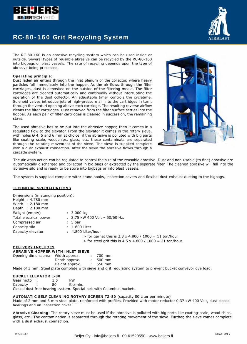
AIRBLAST
PAGE 154
RC-80-160 Grit Recycling System
The RC-80-160 is an abrasive recycling system which can be used inside or outside. Several types of reusable abrasive can be recycled by the RC-80-160 into bigbags or blast vessels. The rate of recycling depends upon the type of abrasive being processed.
Operating principle:Dust laden air enters through the inlet plenum of the collector, where heavy particles fall immediately into the hopper. As the air flows through the filter cartridges, dust is deposited on the outside of the filtering media. The filter cartridges are cleaned automatically and continually without interrupting the operation of the dust collector. An adjustable timer controls the cycletime. Solenoid valves introduce jets of high-pressure air into the cartridges in turn, through the venturi opening above each cartridge. The resulting reverse airflow cleans the filter cartridges. Dust removed from the filter surface settles into the hopper. As each pair of filter cartridges is cleaned in succession, the remaining stays.
The used abrasive has to be put into the abrasive hopper, then it comes in a regulated flow to the elevator. From the elevator it comes in the rotary sieve, with holes Ø 4, 5 and 6 mm at choice, if the abrasive is polluted with big parts like coating scale, woodchips, glass, etc. these contaminats are separated through the rotating movement of the sieve. The sieve is supplied complete with a dust exhaust connection. After the sieve the abrasive flowis through a cascade system.
TECHNICAL SPECIFICATIONS
Dimensions (in standing position): Height : 4.780 mmWidth : 2.180 mmDepth : 2.180 mmWeight (empty) : 3.000 kgTotal electrical power : 2,75 kW 400 Volt – 50/60 Hz.Compressed air : 5 barCapacity silo : 1.600 LiterCapacity elevator : 4.800 Liter/hour
> for garnet this is 2,3 x 4.800 / 1000 = 11 ton/hour> for steel grit this is 4,5 x 4.800 / 1000 = 21 ton/hour
DELIVERY INCLUDESABRASIVE HOPPER WITH INLET SIEVEOpening dimensions: Width approx. : 700 mm
Depth approx. : 500 mm Height approx. : 650 mm
Made of 3 mm. Steel plate complete with sieve and grit regulating system to prevent bucket conveyor overload.
BUCKET ELEVATOR E-80Gear motor : 1,5 kWCapacity : 80 ltr./min.Closed dust free bearing system. Special belt with Columbus buckets.
AUTOMATIC SELF CLEANING ROTARY SCREEN TZ-80 (capacity 80 Liter per minute)Made of 2 mm and 3 mm steel plate, reinforced with profiles. Provided with motor reductor 0,37 kW 400 Volt, dust-closed bearings and an inspection cover.
Abrasive Cleaning: The rotary sieve must be used if the abrasive is polluted with big parts like coating-scale, wood chips, glass, etc.. The contamination is separated through the rotating movement of the sieve. Further, the sieve comes complete with a dust exhaust connection.
The air wash action can be regulated to control the size of the reusable abrasive. Dust and non-usable (to fine) abrasive are automatically discharged and collected in big bags or extracted by the separate filter. The cleaned abrasive will fall into the abrasive silo and is ready to be store into bigbags or into blast vessels.
The system is supplied complete with: crane hooks, inspection covers and flexibel dust-exhaust ducting to the bigbags.
SECTION 7Beijer Oy - [email protected] - 09-61520550 - www.beijers.fi

AIRBLAST
PAGE 155
RC-80-160 Grit Recycling System
GRIT CLEANING SYSTEMConsisting of one heavy-duty cascade system with double air wash action of the abrasive, mounted directly onto the outlet of the elevator. Oversized materials are separated by screens in the bucket elevator hopper. Cascade cleaner is connecting with a sucting ducting Ø 180 mm to the filterunit.The air wash action can be regulated to control the size of re-usable abrasive. The dust and non-useable abrasive (too fine) are discharged automatically and collected in big bags or extracted by the separate filter.
Technical specificationsExhaust capacity : 960 m³/hTotal pressure : 1.200 PaMotor power : 0.75 Kw, 400 Volt, 3-Ph, 50 HzFilter cartridge : 1 pc. Ø 325 x 1000 mmFilter area : 15 m²Filter material : polyester fabricFilter percentage : 99,9 %Max. dust emmision : < 1,5 mg/nm³Cleaning : continuous by compr. air max. 5 barSolenoid valves : 1 pcs (1” G)Cleaning pressure : 4 barCycle time : adjustableSequence : 1 cartridge simultaneousDust collecting bags : PVC bag
ABRASIVE STORAGE SILO 1500 LTRSilo constructed of 3mm steel plate and profiles complete with abrasive stop and connection for 2 bigbags or 2 blast vessels.
ELECTRIC PANEL Complete with automatic switch controllers, mainswitch, failure lamp and control buttons.
STEEL FRAME CONSTRUCTIONAll components are mounted within a sturdy steel frame complete with crane hooks, so in this case the unit is easy to transport and requires little down-time to set up.All components are mounted within a sturdy steel frame, so the unit is easy to transport and requires little downtime to set up.
SECTION 7
7
Beijer Oy - [email protected] - 09-61520550 - www.beijers.fi
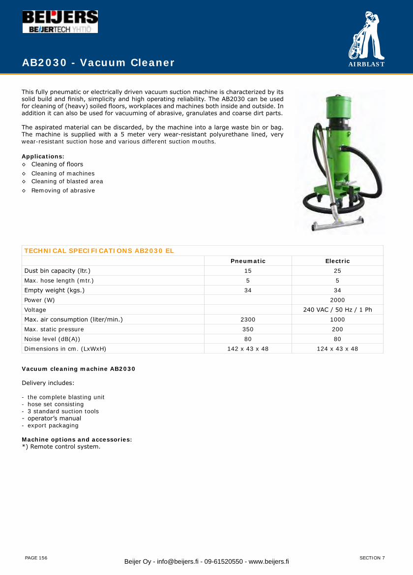
AIRBLAST
PAGE 156
AB2030 - Vacuum Cleaner
This fully pneumatic or electrically driven vacuum suction machine is characterized by its solid build and finish, simplicity and high operating reliability. The AB2030 can be used for cleaning of (heavy) soiled floors, workplaces and machines both inside and outside. In addition it can also be used for vacuuming of abrasive, granulates and coarse dirt parts.
The aspirated material can be discarded, by the machine into a large waste bin or bag. The machine is supplied with a 5 meter very wear-resistant polyurethane lined, very wear-resistant suction hose and various different suction mouths. Applications:◊ Cleaning of floors◊ Cleaning of machines◊ Cleaning of blasted area◊ Removing of abrasive
TECHNICAL SPECIFICATIONS AB2030 ELPneumatic Electric
Dust bin capacity (ltr.) 15 25Max. hose length (mtr.) 5 5Empty weight (kgs.) 34 34Power (W) 2000Voltage 240 VAC / 50 Hz / 1 PhMax. air consumption (liter/min.) 2300 1000Max. static pressure 350 200Noise level (dB(A)) 80 80Dimensions in cm. (LxWxH) 142 x 43 x 48 124 x 43 x 48
Vacuum cleaning machine AB2030
Delivery includes:
- the complete blasting unit- hose set consisting - 3 standard suction tools- operator’s manual- export packaging
Machine options and accessories:*) Remote control system.
SECTION 7Beijer Oy - [email protected] - 09-61520550 - www.beijers.fi
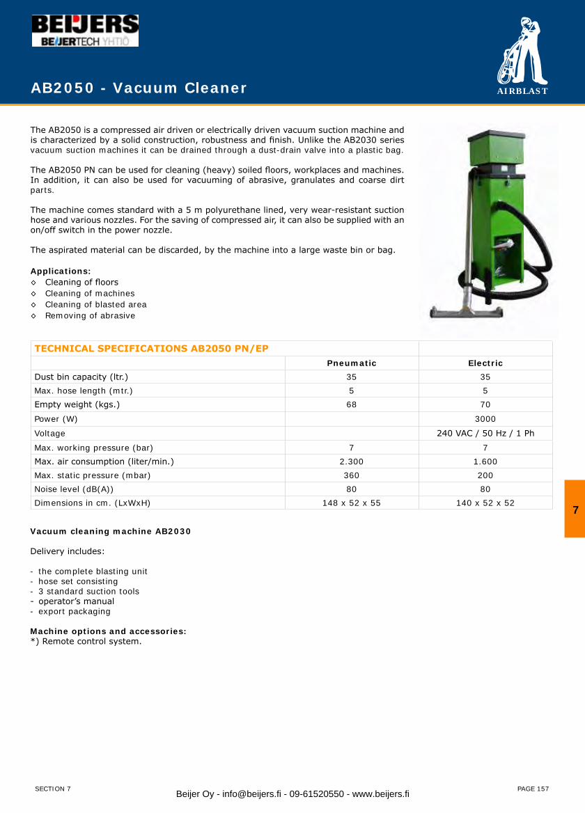
AIRBLAST
PAGE 157
AB2050 - Vacuum Cleaner
The AB2050 is a compressed air driven or electrically driven vacuum suction machine and is characterized by a solid construction, robustness and finish. Unlike the AB2030 series vacuum suction machines it can be drained through a dust-drain valve into a plastic bag.
The AB2050 PN can be used for cleaning (heavy) soiled floors, workplaces and machines. In addition, it can also be used for vacuuming of abrasive, granulates and coarse dirt parts.
The machine comes standard with a 5 m polyurethane lined, very wear-resistant suction hose and various nozzles. For the saving of compressed air, it can also be supplied with an on/off switch in the power nozzle.
The aspirated material can be discarded, by the machine into a large waste bin or bag.
Applications:◊ Cleaning of floors◊ Cleaning of machines◊ Cleaning of blasted area◊ Removing of abrasive
TECHNICAL SPECIFICATIONS AB2050 PN/EPPneumatic Electric
Dust bin capacity (ltr.) 35 35Max. hose length (mtr.) 5 5Empty weight (kgs.) 68 70
Power (W) 3000
Voltage 240 VAC / 50 Hz / 1 Ph
Max. working pressure (bar) 7 7Max. air consumption (liter/min.) 2.300 1.600Max. static pressure (mbar) 360 200Noise level (dB(A)) 80 80Dimensions in cm. (LxWxH) 148 x 52 x 55 140 x 52 x 52
Vacuum cleaning machine AB2030
Delivery includes:
- the complete blasting unit- hose set consisting- 3 standard suction tools- operator’s manual- export packaging
Machine options and accessories:*) Remote control system.
7
SECTION 7 Beijer Oy - [email protected] - 09-61520550 - www.beijers.fi
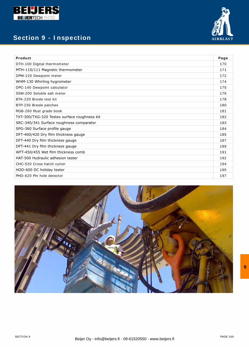
AIRBLAST
PAGE 169
Product PageDTH-100 Digital thermometer 170MTH-110/111 Magnetic thermometer 171DPM-120 Dewpoint meter 172WHM-130 Whirling hygrometer 174DPC-140 Dewpoint calculator 175SSM-200 Soluble salt meter 176BTK-220 Bresle test kit 178BTP-230 Bresle patches 180RGB-260 Rust grade book 181TXT-300/TXG-320 Testex surface roughness kit 182SRC-340/341 Surface roughness comparator 183SPG-360 Surface profile gauge 184DFT-400/420 Dry film thickness gauge 185DFT-440 Dry film thickness gauge 187DFT-441 Dry film thickness gauge 189WFT-450/455 Wet film thickness comb 191HAT-500 Hydraulic adhesion tester 192CHC-520 Cross hatch cutter 194HOD-600 DC holiday tester 195PHD-620 Pin hole detector 197
Section 9 - Inspection
9
SECTION 9 Beijer Oy - [email protected] - 09-61520550 - www.beijers.fi
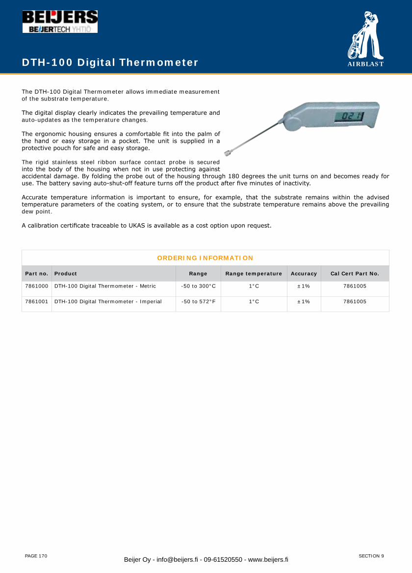
AIRBLAST
PAGE 170
The DTH-100 Digital Thermometer allows immediate measurement of the substrate temperature.
The digital display clearly indicates the prevailing temperature and auto-updates as the temperature changes.
The ergonomic housing ensures a comfortable fit into the palm of the hand or easy storage in a pocket. The unit is supplied in a protective pouch for safe and easy storage.
The rigid stainless steel ribbon surface contact probe is secured into the body of the housing when not in use protecting against accidental damage. By folding the probe out of the housing through 180 degrees the unit turns on and becomes ready for use. The battery saving auto-shut-off feature turns off the product after five minutes of inactivity.
Accurate temperature information is important to ensure, for example, that the substrate remains within the advised temperature parameters of the coating system, or to ensure that the substrate temperature remains above the prevailing dew point.
A calibration certificate traceable to UKAS is available as a cost option upon request.
DTH-100 Digital Thermometer
ORDERING INFORMATION
Part no. Product Range Range temperature Accuracy Cal Cert Part No.
7861000 DTH-100 Digital Thermometer - Metric -50 to 300°C 1°C ±1% 7861005
7861001 DTH-100 Digital Thermometer - Imperial -50 to 572°F 1°C ±1% 7861005
SECTION 9Beijer Oy - [email protected] - 09-61520550 - www.beijers.fi
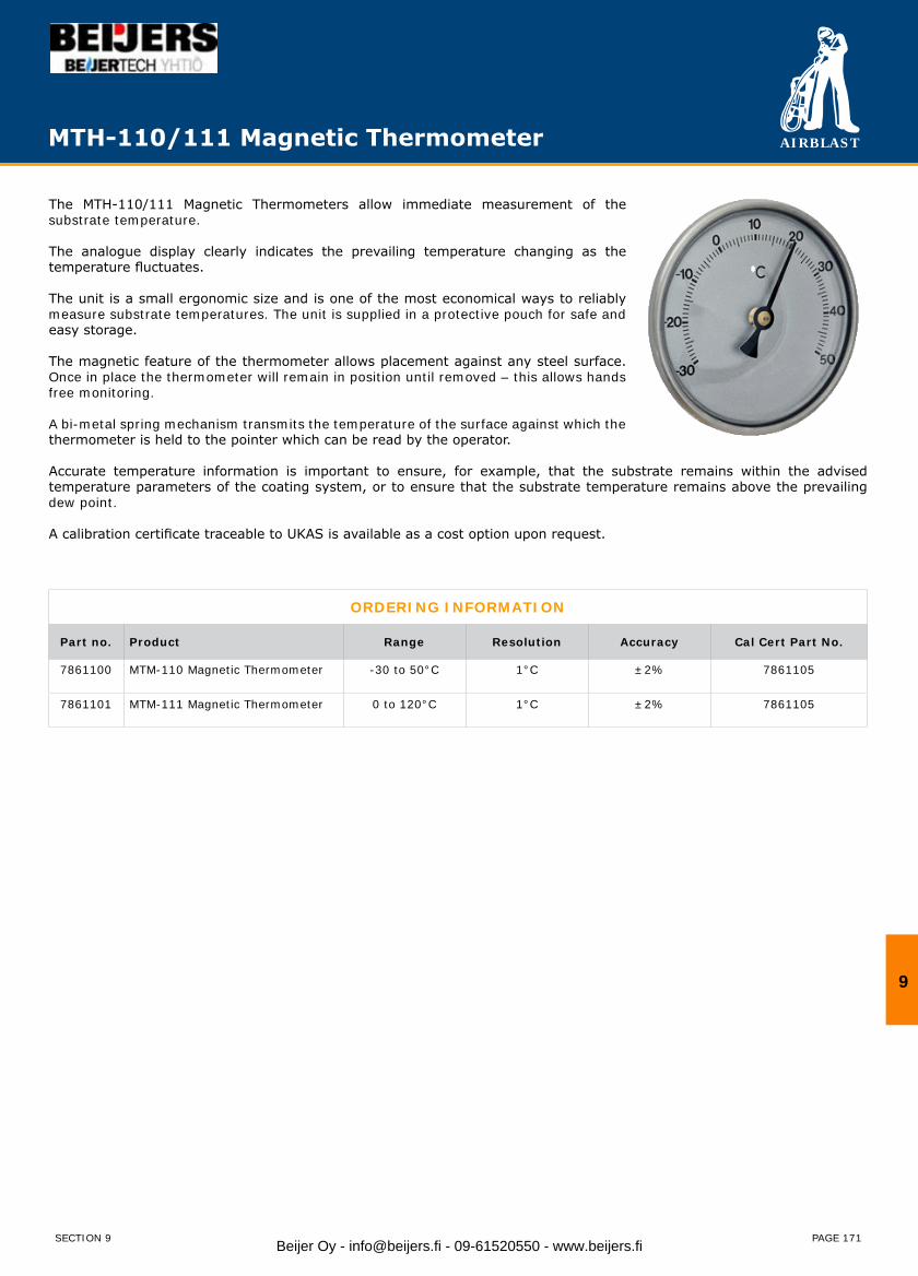
AIRBLAST
PAGE 171
The MTH-110/111 Magnetic Thermometers allow immediate measurement of the substrate temperature.
The analogue display clearly indicates the prevailing temperature changing as the temperature fluctuates.
The unit is a small ergonomic size and is one of the most economical ways to reliably measure substrate temperatures. The unit is supplied in a protective pouch for safe and easy storage.
The magnetic feature of the thermometer allows placement against any steel surface. Once in place the thermometer will remain in position until removed – this allows hands free monitoring.
A bi-metal spring mechanism transmits the temperature of the surface against which the thermometer is held to the pointer which can be read by the operator.
Accurate temperature information is important to ensure, for example, that the substrate remains within the advised temperature parameters of the coating system, or to ensure that the substrate temperature remains above the prevailing dew point.
A calibration certificate traceable to UKAS is available as a cost option upon request.
ORDERING INFORMATION
Part no. Product Range Resolution Accuracy Cal Cert Part No.
7861100 MTM-110 Magnetic Thermometer -30 to 50°C 1°C ±2% 7861105
7861101 MTM-111 Magnetic Thermometer 0 to 120°C 1°C ±2% 7861105
MTH-110/111 Magnetic Thermometer
9
SECTION 9 Beijer Oy - [email protected] - 09-61520550 - www.beijers.fi
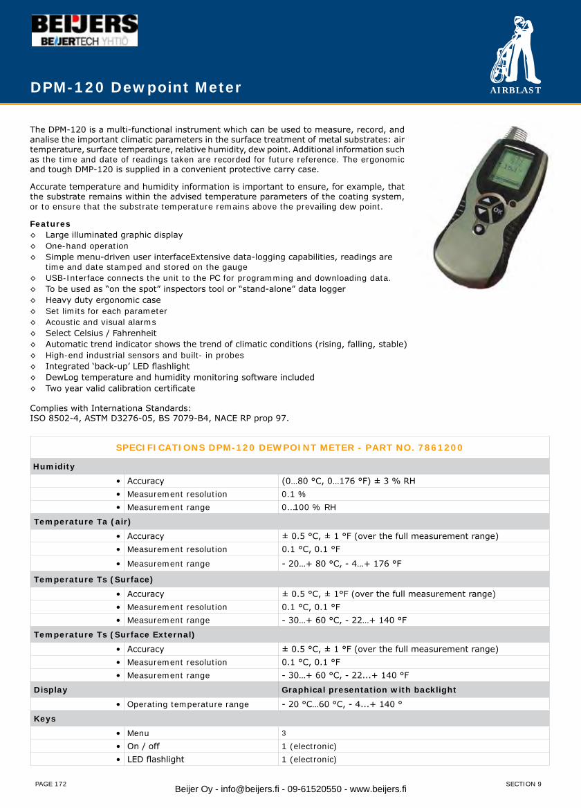
AIRBLAST
PAGE 172
The DPM-120 is a multi-functional instrument which can be used to measure, record, and analise the important climatic parameters in the surface treatment of metal substrates: air temperature, surface temperature, relative humidity, dew point. Additional information such as the time and date of readings taken are recorded for future reference. The ergonomic and tough DMP-120 is supplied in a convenient protective carry case.
Accurate temperature and humidity information is important to ensure, for example, that the substrate remains within the advised temperature parameters of the coating system, or to ensure that the substrate temperature remains above the prevailing dew point.
Features◊ Large illuminated graphic display◊ One-hand operation◊ Simple menu-driven user interfaceExtensive data-logging capabilities, readings are time and date stamped and stored on the gauge◊ USB-Interface connects the unit to the PC for programming and downloading data.◊ To be used as “on the spot” inspectors tool or “stand-alone” data logger◊ Heavy duty ergonomic case◊ Set limits for each parameter◊ Acoustic and visual alarms◊ Select Celsius / Fahrenheit◊ Automatic trend indicator shows the trend of climatic conditions (rising, falling, stable)◊ High-end industrial sensors and built- in probes◊ Integrated ‘back-up’ LED flashlight◊ DewLog temperature and humidity monitoring software included◊ Two year valid calibration certificate
Complies with Internationa Standards:ISO 8502-4, ASTM D3276-05, BS 7079-B4, NACE RP prop 97.
DPM-120 Dewpoint Meter
SPECIFICATIONS DPM-120 DEWPOINT METER - PART NO. 7861200
Humidity
• Accuracy (0…80 °C, 0…176 °F) ± 3 % RH• Measurement resolution 0.1 %• Measurement range 0…100 % RH
Temperature Ta (air)
• Accuracy ± 0.5 °C, ± 1 °F (over the full measurement range)• Measurement resolution 0.1 °C, 0.1 °F
• Measurement range - 20…+ 80 °C, - 4…+ 176 °F
Temperature Ts (Surface)
• Accuracy ± 0.5 °C, ± 1°F (over the full measurement range)• Measurement resolution 0.1 °C, 0.1 °F• Measurement range - 30…+ 60 °C, - 22…+ 140 °F
Temperature Ts (Surface External)
• Accuracy ± 0.5 °C, ± 1 °F (over the full measurement range)• Measurement resolution 0.1 °C, 0.1 °F• Measurement range - 30…+ 60 °C, - 22...+ 140 °F
Display Graphical presentation with backlight
• Operating temperature range - 20 °C…60 °C, - 4...+ 140 °
Keys
• Menu 3
• On / off 1 (electronic)• LED flashlight 1 (electronic)
SECTION 9Beijer Oy - [email protected] - 09-61520550 - www.beijers.fi
AIRBLAST
PAGE 173
Memory
• Type Dynamic• Memory size manual logging 6000 records• Record content manual logging time/date, humidity,Ta, Ts, Td,Tdelta, status byte for alarm.• Memory size interval logging 12000 records
• Record content interval logging R Humidity, Ta and Ts. Other parameters and date and time are calculated.
• Batches 8 Batches max.
Measurement / Features
• Limits Adjustable for each parameter• Lo-Hi Alarms Beep sound , symbol in display and RED Led.• Hold/freeze function Yes
• Data storage Two modes: Manual and interval(auto)
• Data recall Gauge displays average, min/max of each batch.Downloading to PC possible via optional adapter.
• Battery indicator Yes, detailed.• Trend indicator Yes
• User interface Menudriven through up/down/enter key.• Languages 4 languages, English, German, French, Spanish• Extra Built-in bright white LED orientation flashlight.
DPM-120 Dewpoint Meter
9
SECTION 9 Beijer Oy - [email protected] - 09-61520550 - www.beijers.fi
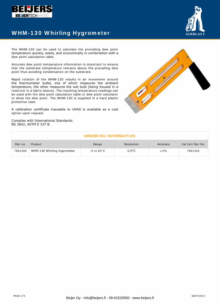
AIRBLAST
PAGE 174
The WHM-130 can be used to calculate the prevailing dew point temperature quickly, easily, and economically in combination with a dew point calculation table.
Accurate dew point temperature information is important to ensure that the substrate temperature remains above the prevailing dew point thus avoiding condensation on the substrate.
Rapid rotation of the WHM-130 results in air movement around the thermometer bulbs, one of which measures the ambient temperature, the other measures the wet bulb (being housed in a reservoir in a fabric sleeve). The resulting temperature readings can be used with the dew point calculation table or dew point calculator to show the dew point. The WHM-130 is supplied in a hard plastic protective case.
A calibration certificate traceable to UKAS is available as a cost option upon request.
Complies with International Standards:BS 2842, ASTM E 337 B.
ORDERING INFORMATION
Part no. Product Range Resolution Accuracy Cal Cert Part No.
7861300 WHM-130 Whirling Hygrometer -5 to 50°C 0,5°C ±2% 7861320
WHM-130 Whirling Hygrometer
SECTION 9Beijer Oy - [email protected] - 09-61520550 - www.beijers.fi
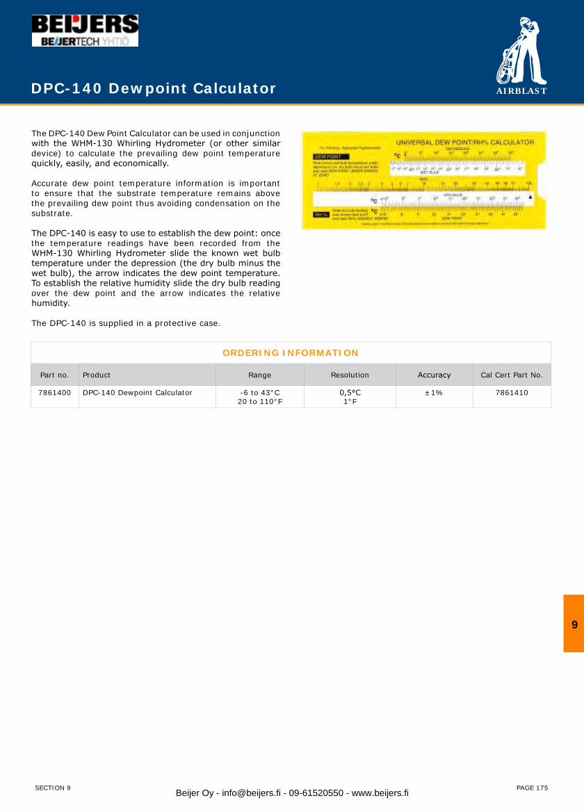
AIRBLAST
PAGE 175
The DPC-140 Dew Point Calculator can be used in conjunction with the WHM-130 Whirling Hydrometer (or other similar device) to calculate the prevailing dew point temperature quickly, easily, and economically.
Accurate dew point temperature information is important to ensure that the substrate temperature remains above the prevailing dew point thus avoiding condensation on the substrate.
The DPC-140 is easy to use to establish the dew point: once the temperature readings have been recorded from the WHM-130 Whirling Hydrometer slide the known wet bulb temperature under the depression (the dry bulb minus the wet bulb), the arrow indicates the dew point temperature. To establish the relative humidity slide the dry bulb reading over the dew point and the arrow indicates the relative humidity.
The DPC-140 is supplied in a protective case.
ORDERING INFORMATION
Part no. Product Range Resolution Accuracy Cal Cert Part No.
7861400 DPC-140 Dewpoint Calculator -6 to 43°C20 to 110°F
0,5°C1°F
±1% 7861410
DPC-140 Dewpoint Calculator
9
SECTION 9 Beijer Oy - [email protected] - 09-61520550 - www.beijers.fi
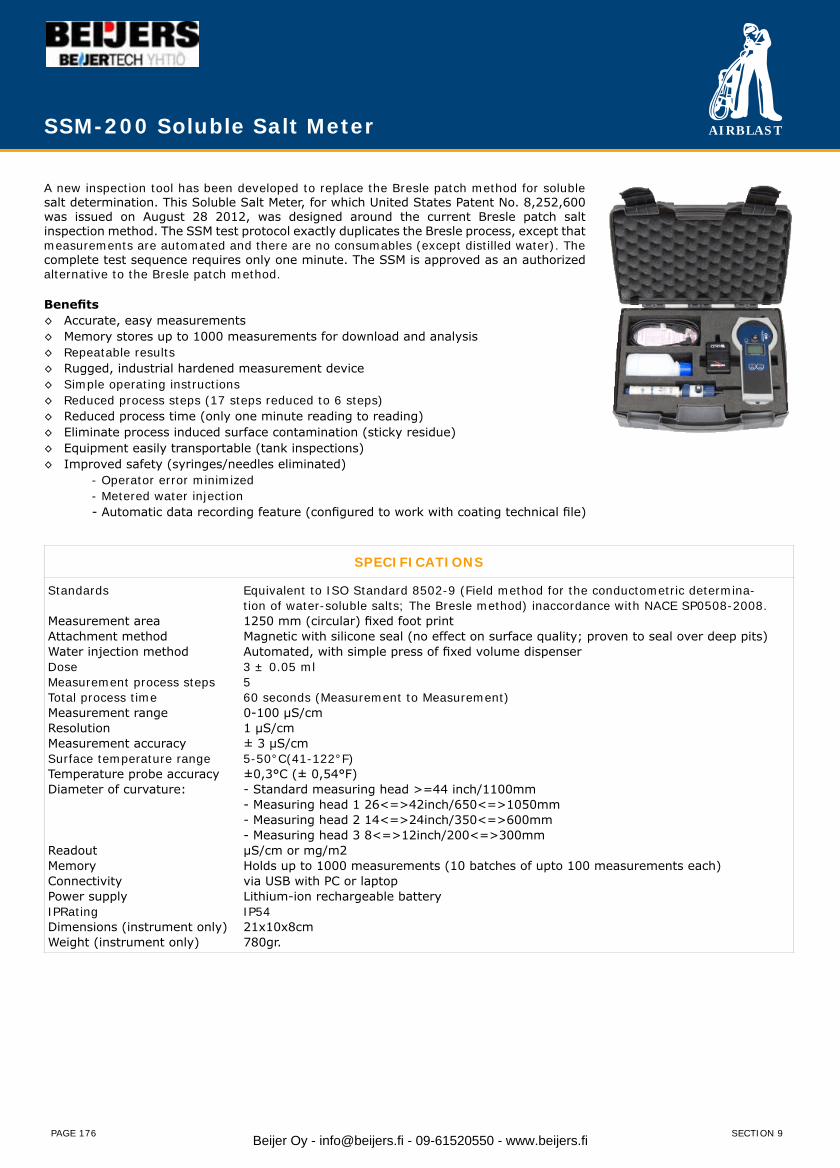
AIRBLAST
PAGE 176
A new inspection tool has been developed to replace the Bresle patch method for soluble salt determination. This Soluble Salt Meter, for which United States Patent No. 8,252,600 was issued on August 28 2012, was designed around the current Bresle patch salt inspection method. The SSM test protocol exactly duplicates the Bresle process, except that measurements are automated and there are no consumables (except distilled water). The complete test sequence requires only one minute. The SSM is approved as an authorized alternative to the Bresle patch method.
Benefits◊ Accurate, easy measurements◊ Memory stores up to 1000 measurements for download and analysis◊ Repeatable results◊ Rugged, industrial hardened measurement device◊ Simple operating instructions◊ Reduced process steps (17 steps reduced to 6 steps)◊ Reduced process time (only one minute reading to reading)◊ Eliminate process induced surface contamination (sticky residue)◊ Equipment easily transportable (tank inspections)◊ Improved safety (syringes/needles eliminated) - Operator error minimized - Metered water injection - Automatic data recording feature (configured to work with coating technical file)
SPECIFICATIONS
Standards Equivalent to ISO Standard 8502-9 (Field method for the conductometric determina- tion of water-soluble salts; The Bresle method) inaccordance with NACE SP0508-2008. Measurement area 1250 mm (circular) fixed foot print Attachment method Magnetic with silicone seal (no effect on surface quality; proven to seal over deep pits)Water injection method Automated, with simple press of fixed volume dispenserDose 3 ± 0.05 ml Measurement process steps 5Total process time 60 seconds (Measurement to Measurement) Measurement range 0-100 µS/cmResolution 1 µS/cmMeasurement accuracy ± 3 µS/cmSurface temperature range 5-50°C(41-122°F)Temperature probe accuracy ±0,3°C (± 0,54°F)Diameter of curvature: - Standard measuring head >=44 inch/1100mm - Measuring head 1 26<=>42inch/650<=>1050mm - Measuring head 2 14<=>24inch/350<=>600mm - Measuring head 3 8<=>12inch/200<=>300mmReadout µS/cm or mg/m2Memory Holds up to 1000 measurements (10 batches of upto 100 measurements each)Connectivity via USB with PC or laptopPower supply Lithium-ion rechargeable batteryIPRating IP54Dimensions (instrument only) 21x10x8cmWeight (instrument only) 780gr.
SSM-200 Soluble Salt Meter
SECTION 9Beijer Oy - [email protected] - 09-61520550 - www.beijers.fi
AIRBLAST
PAGE 177
ORDERING INFORMATION
The SSM can be purchased in two versions: the “Lite” version which includes 50 measurements with the possibility to purchase additional measurements as and when required, and the “Unlimited” version which can take unlimited readings. The “Lite” version provides the possibility to reduce the initial purchase price of the SSM and to purchase additional readings for specific projects. The “Lite” version can be upgraded to the “Unlimited” version by purchasing a licence.
Part no. Description
7862000 SSM-200 Soluble Salt Meter Kit (“Unlimited” version), includes:◊ Soluble Salt Meter◊ SSM adapter flat surface◊ Dispenser◊ Power supply◊ USB cable and PC Software◊ Calibration fluid◊ Carrying case◊ Certificate of performance◊ Unlimited credit measurements
7862001 SSM-200 Soluble Salt Meter Kit (“Lite” version). Same as above only with 50 measurements.
7862004 Upgrade license from “Lite” version to “Unlimited” version
7862005 100 measurements
7862011 Adapter pipe diameter 65-105cm (26”-42”)
7862012 Adapter pipe diameter 35-60cm (14”-24”)
7862013 Adapter pipe diameter 20-30cm (8”-12”)
7862014 Set of adapters pipe diameter 20-105cm (8”-42”)
7862015 Performance check for SSM-200 with certificate
SSM-200 Soluble Salt Meter
9
SECTION 9 Beijer Oy - [email protected] - 09-61520550 - www.beijers.fi
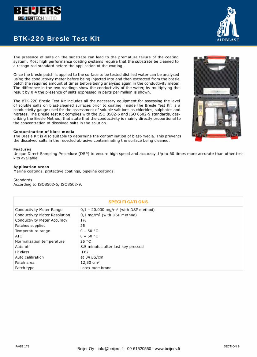
AIRBLAST
PAGE 178
The presence of salts on the substrate can lead to the premature failure of the coating system. Most high performance coating systems require that the substrate be cleaned to a recognized standard before the application of the coating.
Once the bresle patch is applied to the surface to be tested distilled water can be analysed using the conductivity meter before being injected into and then extracted from the bresle patch the required amount of times before being analysed again in the conductivity meter. The difference in the two readings show the conductivity of the water, by multiplying the result by 0.4 the presence of salts expressed in parts per million is shown.
The BTK-220 Bresle Test Kit includes all the necessary equipment for assessing the level of soluble salts on blast-cleaned surfaces prior to coating. Inside the Bresle Test Kit is a conductivity gauge used for the assessment of soluble salt ions as chlorides, sulphates and nitrates. The Bresle Test Kit complies with the ISO 8502-6 and ISO 8502-9 standards, des-cribing the Bresle Method, that state that the conductivity is mainly directly proportional to the concentration of dissolved salts in the solution.
Contamination of blast-mediaThe Bresle Kit is also suitable to determine the contamination of blast-media. This prevents the dissolved salts in the recycled abrasive contaminating the surface being cleaned.
Features Unique Direct Sampling Procedure (DSP) to ensure high speed and accuracy. Up to 60 times more accurate than other test kits available.
Application areasMarine coatings, protective coatings, pipeline coatings.
Standards:According to ISO8502-6, ISO8502-9.
BTK-220 Bresle Test Kit
SPECIFICATIONS
Conductivity Meter RangeConductivity Meter ResolutionConductivity Meter AccuracyPatches suppliedTemperature rangeATCNormalization temperatureAuto offIP classAuto calibrationPatch areaPatch type
0,1 – 20.000 mg/m2 (with DSP method)0,1 mg/m2 (with DSP method)1%250 – 50 °C0 – 50 °C25 °C8.5 minutes after last key pressedIP67at 84 μS/cm12,50 cm2
Latex membrane
SECTION 9Beijer Oy - [email protected] - 09-61520550 - www.beijers.fi
AIRBLAST
PAGE 179
BTK-220 Bresle Test Kit
ORDERING INFORMATION
Part no. Description
7862200 BTK-220 Bresle Test Kit, complete (includes spares as shown below)
Spares
7862210 Bresle patches (pack of 25)
7862220 Digital Conductivity Meter (waterproof)
7862221 Cleansing solution 50ml
7862222 Calibration solution 84 μS, 50ml
7862223 Cup 25ml
7862230 Syringe incl. needle 2,5ml
7862231 Syringe without needle 20ml
7862232 Needle
7862240 Deionised water 200ml
Optional
7862211 Calibration Certificate for BTK-220
7862212 ISO 17025 approved certificate of patches
7862213 Bresle area mask magnet
On request
Beaker for testing of blast media 100ml
Standard delivery includes◊ Digital conductivity meter◊ Bresle patches 25 pcs.◊ Cleansing solution 50ml / Calibration solution 84 μS 50ml / Deionised water 200ml◊ Cups, Syringes and needle◊ Instruction manual
Special care◊ Always clean the instrument after use and keep the instrument in its case when not in use.◊ Depending on the frequency of use, a thin film may occur on the probe. Use a clean cotton swap and cleansing solution to remove this.
9
SECTION 9 Beijer Oy - [email protected] - 09-61520550 - www.beijers.fi

AIRBLAST
PAGE 180
The Bresle patch is a self-adhesive film patch for taking samples of soluble impurities on a test surface.
ApplicationSurface contaminants, such as salt, may cause coating failure and increase maintenance costs for vessels, industry buildings and steel structures in general. Coating failure such as blistering and corrosion may be the result of a too high level of salt prior to painting. The Bresle Method described in the ISO 8502-6 is commonly used to measure the level of surface salts prior to coating. A so-called Bresle patch (a small self-adhesive plastic patch) with a washed latex membrane and a known surface area is used to dissolve the soluble salts. can be used to check for the presence of salts such as chlorides and sulphates on the substrate prior to the application of the coating.
ORDERING INFORMATION
Part no. 7862210
Description Bresle patches (packed in a plastic container per 25 pcs.)
TechnicalSpecifications
Size Sample volumeTest AreaStresstest
: 5 x 5 cm (2.0”x 2.0”): 2.5 ml.: 12.5 cm² (1.93 sq. inches): Meets ISO8502-6 Annex A.
Material Elastic filmTapeProtective paper
: Latex: PE with acrylic based adhesive: Coated
One Bresle patch contributes with less than 8 mg NaCI/m² (0,8μg Na/CI/cm²)>.
Certification Each production batch of Airblast Bresle patches is certified by an ISO 17025 accredited test laboratory.
Storage Store in a cool and dark place. Keep Bresle patch away from direct sunlight.
BTP-230 Bresle Patches
SECTION 9Beijer Oy - [email protected] - 09-61520550 - www.beijers.fi
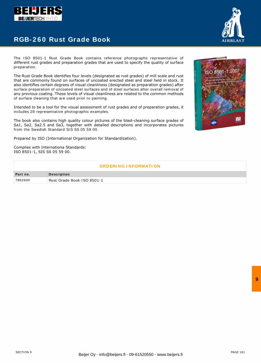
AIRBLAST
PAGE 181
The ISO 8501-1 Rust Grade Book contains reference photographs representative of different rust grades and preparation grades that are used to specify the quality of surface preparation.
The Rust Grade Book identifies four levels (designated as rust grades) of mill scale and rust that are commonly found on surfaces of uncoated erected steel and steel held in stock. It also identifies certain degrees of visual cleanliness (designated as preparation grades) after surface preparation of uncoated steel surfaces and of steel surfaces after overall removal of any previous coating. These levels of visual cleanliness are related to the common methods of surface cleaning that are used prior to painting.
Intended to be a tool for the visual assessment of rust grades and of preparation grades, it includes 28 representative photographic examples.
The book also contains high quality colour pictures of the blast-cleaning surface grades of Sa1, Sa2, Sa2.5 and Sa3, together with detailed descriptions and incorporates pictures from the Swedish Standard SIS SS 05 59 00.
Prepared by ISO (International Organization for Standardization).
Complies with Internationa Standards:ISO 8501-1, SIS SS 05 59 00.
RGB-260 Rust Grade Book
ORDERING INFORMATION
Part no. Description
7862600 Rust Grade Book ISO 8501-1
9
SECTION 9 Beijer Oy - [email protected] - 09-61520550 - www.beijers.fi
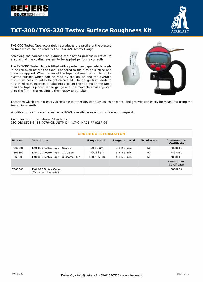
AIRBLAST
PAGE 182
TXG-300 Testex Tape accurately reproduces the profile of the blasted surface which can be read by the TXG-320 Testex Gauge.
Achieving the correct profile during the blasting process is critical to ensure that the coating system to be applied performs correctly.
The TXG-300 Testex Tape is fitted with a protective paper which needs to be removed before the tape is adhered to the blasted surface and pressure applied. When removed the tape features the profile of the blasted surface which can be read by the gauge and the average maximum peak to valley height calculated. The gauge first needs to be zeroed to 50 microns to take into account the backing on the tape, then the tape is placed in the gauge and the movable anvil adjusted onto the film – the reading is then ready to be taken.
ORDERING INFORMATION
Part no. Description Range Metric Range Imperial Nr. of tests Conformance Certificate
7863301 TXG-300 Testex Tape - Coarse 20-50 μm 0.8-2.0 mils 50 7863011
7863302 TXG-300 Testex Tape - X-Coarse 40-115 μm 1.5-4.5 mils 50 7863011
7863303 TXG-300 Testex Tape - X-Coarse Plus 100-125 μm 4.0-5.0 mils 50 7863011
CalibrationCertificate
7863200 TXG-320 Testex Gauge (Metric and Imperial)
7863205
TXT-300/TXG-320 Testex Surface Roughness Kit
Locations which are not easily accessible to other devices such as inside pipes and grooves can easily be measured using the testex tape method.
A calibration certificate traceable to UKAS is available as a cost option upon request.
Complies with International Standards:ISO DIS 8503-3, BS 7079-C5, ASTM D 4417-C, NACE RP 0287-95.
SECTION 9Beijer Oy - [email protected] - 09-61520550 - www.beijers.fi
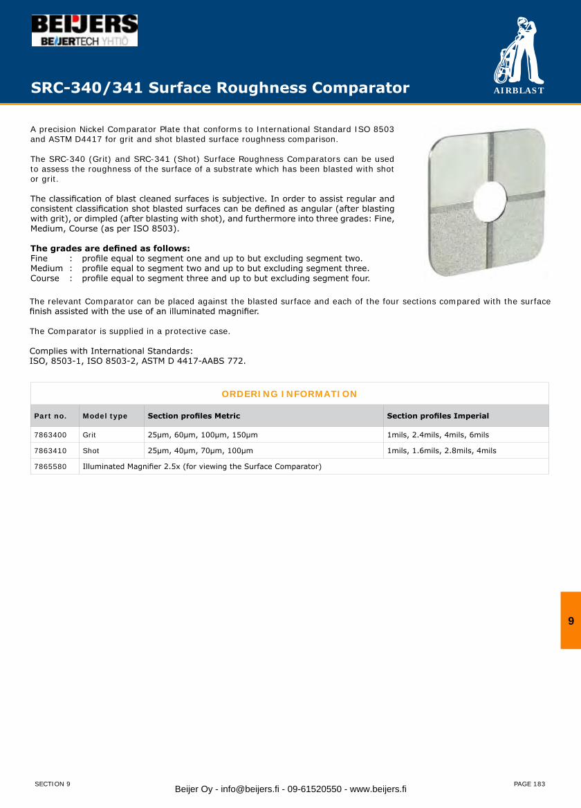
AIRBLAST
PAGE 183
SRC-340/341 Surface Roughness Comparator
A precision Nickel Comparator Plate that conforms to International Standard ISO 8503 and ASTM D4417 for grit and shot blasted surface roughness comparison.
The SRC-340 (Grit) and SRC-341 (Shot) Surface Roughness Comparators can be used to assess the roughness of the surface of a substrate which has been blasted with shot or grit.
The classification of blast cleaned surfaces is subjective. In order to assist regular and consistent classification shot blasted surfaces can be defined as angular (after blasting with grit), or dimpled (after blasting with shot), and furthermore into three grades: Fine, Medium, Course (as per ISO 8503).
The grades are defined as follows:Fine : profile equal to segment one and up to but excluding segment two.Medium : profile equal to segment two and up to but excluding segment three.Course : profile equal to segment three and up to but excluding segment four.
ORDERING INFORMATION
Part no. Model type Section profiles Metric Section profiles Imperial
7863400 Grit 25μm, 60μm, 100μm, 150μm 1mils, 2.4mils, 4mils, 6mils
7863410 Shot 25μm, 40μm, 70μm, 100μm 1mils, 1.6mils, 2.8mils, 4mils
7865580 Illuminated Magnifier 2.5x (for viewing the Surface Comparator)
The relevant Comparator can be placed against the blasted surface and each of the four sections compared with the surface finish assisted with the use of an illuminated magnifier.
The Comparator is supplied in a protective case.
Complies with International Standards:ISO, 8503-1, ISO 8503-2, ASTM D 4417-AABS 772.
9
SECTION 9 Beijer Oy - [email protected] - 09-61520550 - www.beijers.fi
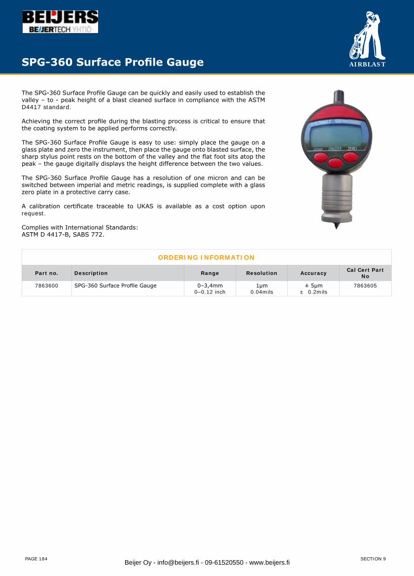
AIRBLAST
PAGE 184
The SPG-360 Surface Profile Gauge can be quickly and easily used to establish the valley – to - peak height of a blast cleaned surface in compliance with the ASTM D4417 standard.
Achieving the correct profile during the blasting process is critical to ensure that the coating system to be applied performs correctly.
The SPG-360 Surface Profile Gauge is easy to use: simply place the gauge on a glass plate and zero the instrument, then place the gauge onto blasted surface, the sharp stylus point rests on the bottom of the valley and the flat foot sits atop the peak – the gauge digitally displays the height difference between the two values.
The SPG-360 Surface Profile Gauge has a resolution of one micron and can be switched between imperial and metric readings, is supplied complete with a glass zero plate in a protective carry case.
A calibration certificate traceable to UKAS is available as a cost option upon request.
Complies with International Standards:ASTM D 4417-B, SABS 772.
ORDERING INFORMATION
Part no. Description Range Resolution Accuracy Cal Cert Part No
7863600 SPG-360 Surface Profile Gauge 0–3,4mm0–0.12 inch
1μm0.04mils
± 5μm± 0.2mils
7863605
SPG-360 Surface Profile Gauge
SECTION 9Beijer Oy - [email protected] - 09-61520550 - www.beijers.fi

AIRBLAST
PAGE 185
The DFT-400 Dry Film Thickness Gauge provides a fast and economical solution to non-destructive dry film thickness assessment on ferrous substrates only. The DFT-420 Dry Film Thickness Gauge provides a fast and economical solution to non-destructive dry film thickness assessment on ferrous and non-ferrous substrates.
In order for coating systems to perform as designed the thickness of each coat of paint must be within tolerances set by the material manufacturer – assessing the dry film thickness of the paint after the coating process is an invaluable tool to ensuring that the thickness of the coating is as specified.
DFT-400/420 SPECIFICATIONS
Measuring Principle Two magnetic measuring principles:Fe: Magnetic-Flux/Hall Effect ref Fe*NFe: Eddy Current (DFT-420 only)
Standards & Regulation DIN EN ISO 2808, ISO 2178, ASTM B 499, ASTM D 7091 (only DFT-420: ISO 2360)Probe Type integrated or - optional - cable probe with 1 m. cableMeasuring Range Fe: 0.0 – 5000 μm or 0.0 – 3000 μm. NFe: 0.0 – 3000 μm (DFT-420 only)Metric System μm / mil YesMeasuring Interval Single measurement: 850 msDisplay Metric from 0.0 – 999 in μm, from 1000 μm in mmResolution 1 μm in the range up to 999 μm, 0.01 mm in the range from 1 mmAccuracy ± ( 2μm + 3% of the readings)Minimum Measuring Area Ø 25 mmMinimum Curvature convex: 5mm, concave: 25mmMinimum Substrate Thickness Fe: 0.2 mm. NFe: 0.05 mm (DFT-420 only)Display Graphic-LCDTemperature Range 0 – 50° CPermitted Storage Temperature -10° C – 60° CPower Supply 2 x Mignon Batteries: 1.5 V (type AA alkaline)Dimensions (L x W x H in mm) 100 x 60 x 27 (gauge with integrated probe)Weight incl. battery Gauge with integrated probe: 105 g. Gauge with cable probe: 147 g
Fe* Measuring of non-ferromagnetic coatings on ferromagnetic substrate, for example measuring on steel- or iron-substrates.NFe* Measuring of non-ferromagnetic and electrically non-conductive coatings (insulating coatings) on non-ferromagnetic
and electrically conductive substrate, for example measuring on aluminum-, zinc-, brass- and certain stainless(high-grade) steel-substrates.
Technical data subject to change without notice.
DFT-400/420 Dry Film Thickness Gauge
The DFT-400 & DFT-420 Dry Film Thickness Gauges are ergonomic and light weight yet tough and reliable, and are powered by standard alkaline batteries. Both units are switched on by placing the probe on the substrate to be measured and feature single button operation and intuitive menus. An audible signal confirms that a reading has been successfully taken and the back lit screen displays readings clearly and quickly. Each gauge is supplied with calibrated for life; this means that there is no requirement to calibrate the gauge before use, or in changing climatic conditions - simply use the zero plate provided to zero the gauge before use, or in changing climatic conditions, to ensure the accuracy of the readings.
Both gauges are available in integral or separate probe design both with an industry leading polished ruby tip ensuring millions of fast, reliable and accurate readings of up to Fe 5000 microns or/and NFe 3000 microns. Each gauge features a sleep mode which turns the unit off after a short period of inactivity, by placing the probe onto a surface to be measured the unit reactivates and is immediately ready for use.
The DFT-400 & DFT-420 are supplied in foam filled hard plastic carry cases with an additional soft plastic pouch for ease of transportation in the job site, reference plates, 2 x 1,5 V Mignon batteries (type AA alkaline), test certificate and instruction manual. Both gauges have hand sizes straps allowing for easy fixing on the wrist or clothes.
9
SECTION 9 Beijer Oy - [email protected] - 09-61520550 - www.beijers.fi
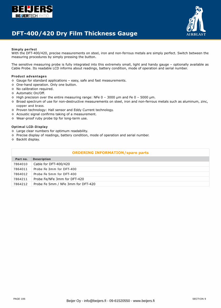
AIRBLAST
PAGE 186
Simply perfectWith the DFT-400/420, precise measurements on steel, iron and non-ferrous metals are simply perfect. Switch between the measuring procedures by simply pressing the button.
The sensitive measuring probe is fully integrated into this extremely small, light and handy gauge – optionally available as Cable Probe. Its readable LCD informs about readings, battery condition, mode of operation and serial number.
Product advantages◊ Gauge for standard applications – easy, safe and fast measurements.◊ One-hand operation. Only one button.◊ No calibration required.◊ Automatic On/Off.◊ High precision over the entire measuring range: NFe 0 – 3000 μm and Fe 0 – 5000 μm.◊ Broad spectrum of use for non-destructive measurements on steel, iron and non-ferrous metals such as aluminum, zinc, copper and brass.◊ Proven technology: Hall sensor and Eddy Current technology.◊ Acoustic signal confirms taking of a measurement.◊ Wear-proof ruby probe tip for long-term use.
Optimal LCD-Display◊ Large clear numbers for optimum readability.◊ Precise display of readings, battery condition, mode of operation and serial number.◊ Backlit display.
ORDERING INFORMATION/spare parts
Part no. Description
7864010 Cable for DFT-400/4207864011 Probe Fe 3mm for DFT-4007864012 Probe Fe 5mm for DFT-4007864211 Probe Fe/NFe 3mm for DFT-4207864212 Probe Fe 5mm / NFe 3mm for DFT-420
DFT-400/420 Dry Film Thickness Gauge
SECTION 9Beijer Oy - [email protected] - 09-61520550 - www.beijers.fi
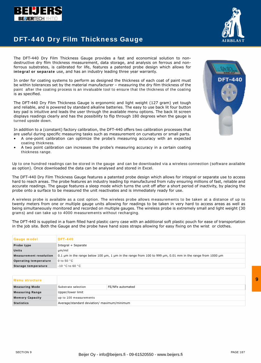
AIRBLAST
PAGE 187
The DFT-440 Dry Film Thickness Gauge provides a fast and economical solution to non-destructive dry film thickness measurement, data storage, and analysis on ferrous and non-ferrous substrates, is calibrated for life, features a patented probe design which allows for integral or separate use, and has an industry leading three year warranty.
In order for coating systems to perform as designed the thickness of each coat of paint must be within tolerances set by the material manufacturer – measuring the dry film thickness of the paint after the coating process is an invaluable tool to ensure that the thickness of the coating is as specified.
The DFT-440 Dry Film Thickness Gauge is ergonomic and light weight (127 gram) yet tough and reliable, and is powered by standard alkaline batteries. The easy to use back lit four button key pad is intuitive and leads the user through the available menu options. The back lit screen displays readings clearly and has the possibility to flip through 180 degrees when the gauge is turned upside down.
In addition to a (constant) factory calibration, the DFT-440 offers two calibration processes that are useful during specific measuring tasks such as measurement on curvatures or small parts.
A one-point calibration can optimize the probe’s measuring accuracy with an expected•coating thickness.A two point calibration can increases the probe’s measuring accuracy in a certain coating•thickness range.
Gauge model DFT-440
Probe type Integral + Separate
Units µm/mil
Measurement resolution 0.1 µm in the range below 100 µm, 1 µm in the range from 100 to 999 µm, 0.01 mm in the range from 1000 µm
Operating temperature 0 to 50 °C
Starage temperature -10 °C to 60 °C
Menu structure
Measuring Mode Substrate selection FE/NFe automated
Measuring Range Upper/lower limit
Memory Capacity up to 100 measurements
Statistics Average/standard deviation/ maximum/minimum
DFT-440 Dry Film Thickness Gauge
Up to one hundred readings can be stored in the gauge and can be downloaded via a wireless connection (software available as option). Once downloaded the data can be analysed and stored in Excel.
The DFT-440 Dry Film Thickness Gauge features a patented probe design which allows for integral or separate use to access hard to reach areas. The probe features an industry leading tip manufactured from ruby ensuring millions of fast, reliable and accurate readings. The gauge features a sleep mode which turns the unit off after a short period of inactivity, by placing the probe onto a surface to be measured the unit reactivates and is immediately ready for use.
A wireless probe is available as a cost option. The wireless probe allows measurements to be taken at a distance of up to twenty meters from one or multiple gauge units allowing for readings to be taken in very hard to access areas as well as being simultaneously monitored and recorded on multiple gauges. The wireless probe is extremely small and light weight (30 grams) and can take up to 4000 measurements without recharging.
The DFT-440 is supplied in a foam filled hard plastic carry case with an additional soft plastic pouch for ease of transportation in the job site. Both the Gauge and the probe have hand sizes straps allowing for easy fixing on the wrist or clothes.
9
SECTION 9 Beijer Oy - [email protected] - 09-61520550 - www.beijers.fi
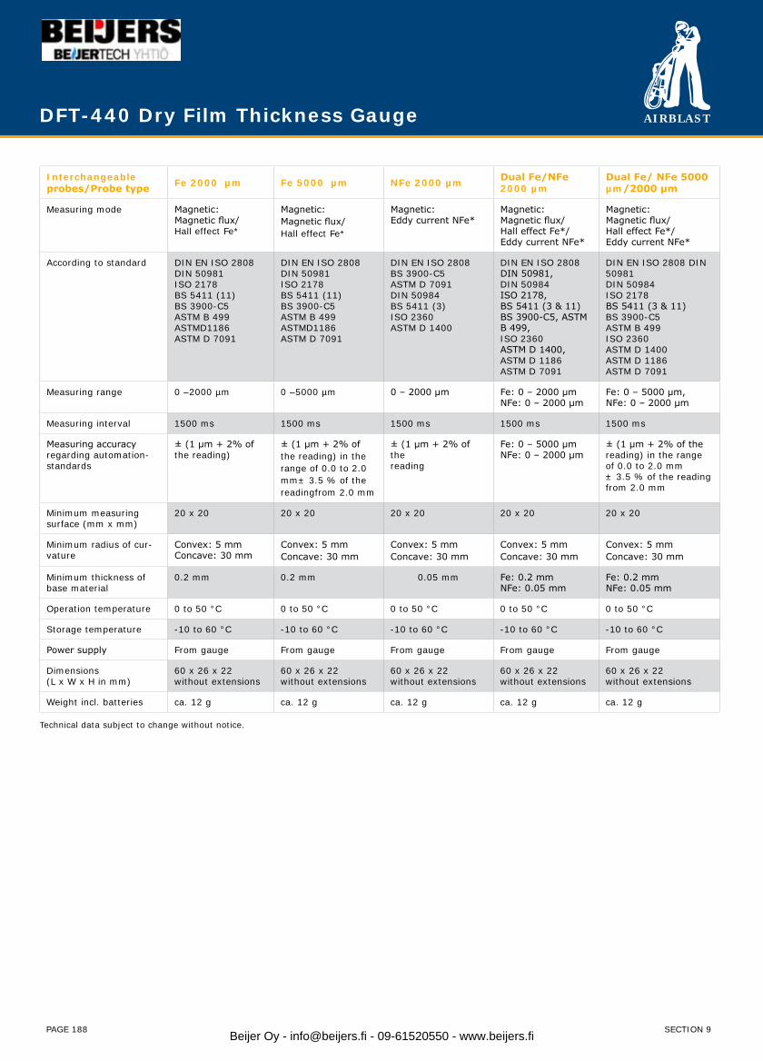
AIRBLAST
PAGE 188
Interchangeable probes/Probe type Fe 2000 µm Fe 5000 µm NFe 2000 µm Dual Fe/NFe
2000 µmDual Fe/ NFe 5000 µm/2000 µm
Measuring mode Magnetic:Magnetic flux/Hall effect Fe*
Magnetic:Magnetic flux/Hall effect Fe*
Magnetic:Eddy current NFe*
Magnetic:Magnetic flux/Hall effect Fe*/Eddy current NFe*
Magnetic:Magnetic flux/Hall effect Fe*/Eddy current NFe*
According to standard DIN EN ISO 2808DIN 50981ISO 2178BS 5411 (11)BS 3900-C5ASTM B 499ASTMD1186ASTM D 7091
DIN EN ISO 2808DIN 50981ISO 2178BS 5411 (11)BS 3900-C5ASTM B 499ASTMD1186ASTM D 7091
DIN EN ISO 2808BS 3900-C5ASTM D 7091DIN 50984BS 5411 (3)ISO 2360ASTM D 1400
DIN EN ISO 2808 DIN 50981,DIN 50984ISO 2178,BS 5411 (3 & 11)BS 3900-C5, ASTM B 499,ISO 2360ASTM D 1400,ASTM D 1186ASTM D 7091
DIN EN ISO 2808 DIN 50981DIN 50984ISO 2178BS 5411 (3 & 11) BS 3900-C5ASTM B 499ISO 2360ASTM D 1400ASTM D 1186ASTM D 7091
Measuring range 0 –2000 µm 0 –5000 µm 0 – 2000 μm Fe: 0 – 2000 μmNFe: 0 – 2000 μm
Fe: 0 – 5000 μm,NFe: 0 – 2000 μm
Measuring interval 1500 ms 1500 ms 1500 ms 1500 ms 1500 ms
Measuring accuracy regarding automation-standards
± (1 µm + 2% of the reading)
± (1 µm + 2% of the reading) in the range of 0.0 to 2.0 mm± 3.5 % of the readingfrom 2.0 mm
± (1 μm + 2% of thereading
Fe: 0 – 5000 μmNFe: 0 – 2000 μm
± (1 μm + 2% of thereading) in the rangeof 0.0 to 2.0 mm± 3.5 % of the reading from 2.0 mm
Minimum measuring surface (mm x mm)
20 x 20 20 x 20 20 x 20 20 x 20 20 x 20
Minimum radius of cur-vature
Convex: 5 mmConcave: 30 mm
Convex: 5 mmConcave: 30 mm
Convex: 5 mmConcave: 30 mm
Convex: 5 mmConcave: 30 mm
Convex: 5 mmConcave: 30 mm
Minimum thickness of base material
0.2 mm 0.2 mm 0.05 mm Fe: 0.2 mmNFe: 0.05 mm
Fe: 0.2 mmNFe: 0.05 mm
Operation temperature 0 to 50 °C 0 to 50 °C 0 to 50 °C 0 to 50 °C 0 to 50 °C
Storage temperature -10 to 60 °C -10 to 60 °C -10 to 60 °C -10 to 60 °C -10 to 60 °C
Power supply From gauge From gauge From gauge From gauge From gauge
Dimensions(L x W x H in mm)
60 x 26 x 22without extensions
60 x 26 x 22without extensions
60 x 26 x 22without extensions
60 x 26 x 22without extensions
60 x 26 x 22without extensions
Weight incl. batteries ca. 12 g ca. 12 g ca. 12 g ca. 12 g ca. 12 g
Technical data subject to change without notice.
DFT-440 Dry Film Thickness Gauge
SECTION 9Beijer Oy - [email protected] - 09-61520550 - www.beijers.fi
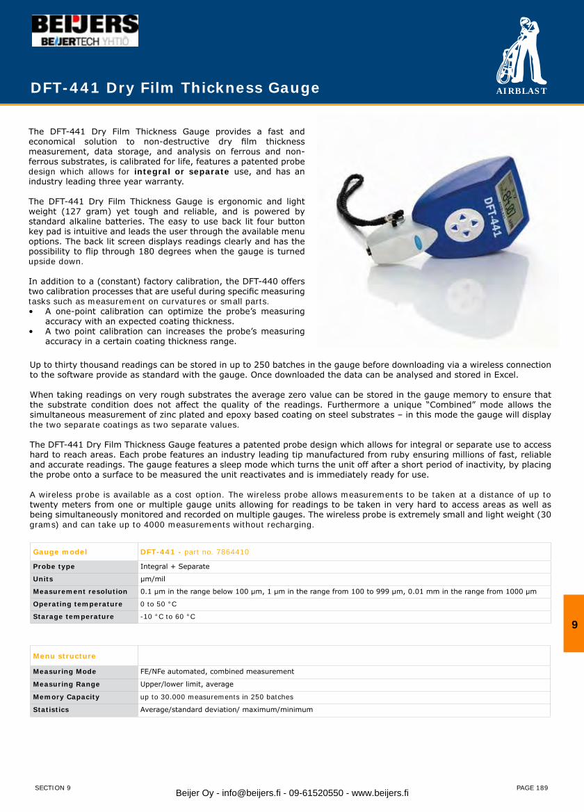
AIRBLAST
PAGE 189
The DFT-441 Dry Film Thickness Gauge provides a fast and economical solution to non-destructive dry film thickness measurement, data storage, and analysis on ferrous and non-ferrous substrates, is calibrated for life, features a patented probe design which allows for integral or separate use, and has an industry leading three year warranty.
The DFT-441 Dry Film Thickness Gauge is ergonomic and light weight (127 gram) yet tough and reliable, and is powered by standard alkaline batteries. The easy to use back lit four button key pad is intuitive and leads the user through the available menu options. The back lit screen displays readings clearly and has the possibility to flip through 180 degrees when the gauge is turned upside down.
In addition to a (constant) factory calibration, the DFT-440 offers two calibration processes that are useful during specific measuring tasks such as measurement on curvatures or small parts.
A one-point calibration can optimize the probe’s measuring • accuracy with an expected coating thickness.A two point calibration can increases the probe’s measuring • accuracy in a certain coating thickness range.
Gauge model DFT-441 - part no. 7864410
Probe type Integral + Separate
Units µm/mil
Measurement resolution 0.1 µm in the range below 100 µm, 1 µm in the range from 100 to 999 µm, 0.01 mm in the range from 1000 µm
Operating temperature 0 to 50 °C
Starage temperature -10 °C to 60 °C
Menu structure
Measuring Mode FE/NFe automated, combined measurement
Measuring Range Upper/lower limit, average
Memory Capacity up to 30.000 measurements in 250 batches
Statistics Average/standard deviation/ maximum/minimum
DFT-441 Dry Film Thickness Gauge
Up to thirty thousand readings can be stored in up to 250 batches in the gauge before downloading via a wireless connection to the software provide as standard with the gauge. Once downloaded the data can be analysed and stored in Excel.
When taking readings on very rough substrates the average zero value can be stored in the gauge memory to ensure that the substrate condition does not affect the quality of the readings. Furthermore a unique “Combined” mode allows the simultaneous measurement of zinc plated and epoxy based coating on steel substrates – in this mode the gauge will display the two separate coatings as two separate values.
The DFT-441 Dry Film Thickness Gauge features a patented probe design which allows for integral or separate use to access hard to reach areas. Each probe features an industry leading tip manufactured from ruby ensuring millions of fast, reliable and accurate readings. The gauge features a sleep mode which turns the unit off after a short period of inactivity, by placing the probe onto a surface to be measured the unit reactivates and is immediately ready for use.
A wireless probe is available as a cost option. The wireless probe allows measurements to be taken at a distance of up to twenty meters from one or multiple gauge units allowing for readings to be taken in very hard to access areas as well as being simultaneously monitored and recorded on multiple gauges. The wireless probe is extremely small and light weight (30 grams) and can take up to 4000 measurements without recharging.
9
SECTION 9 Beijer Oy - [email protected] - 09-61520550 - www.beijers.fi
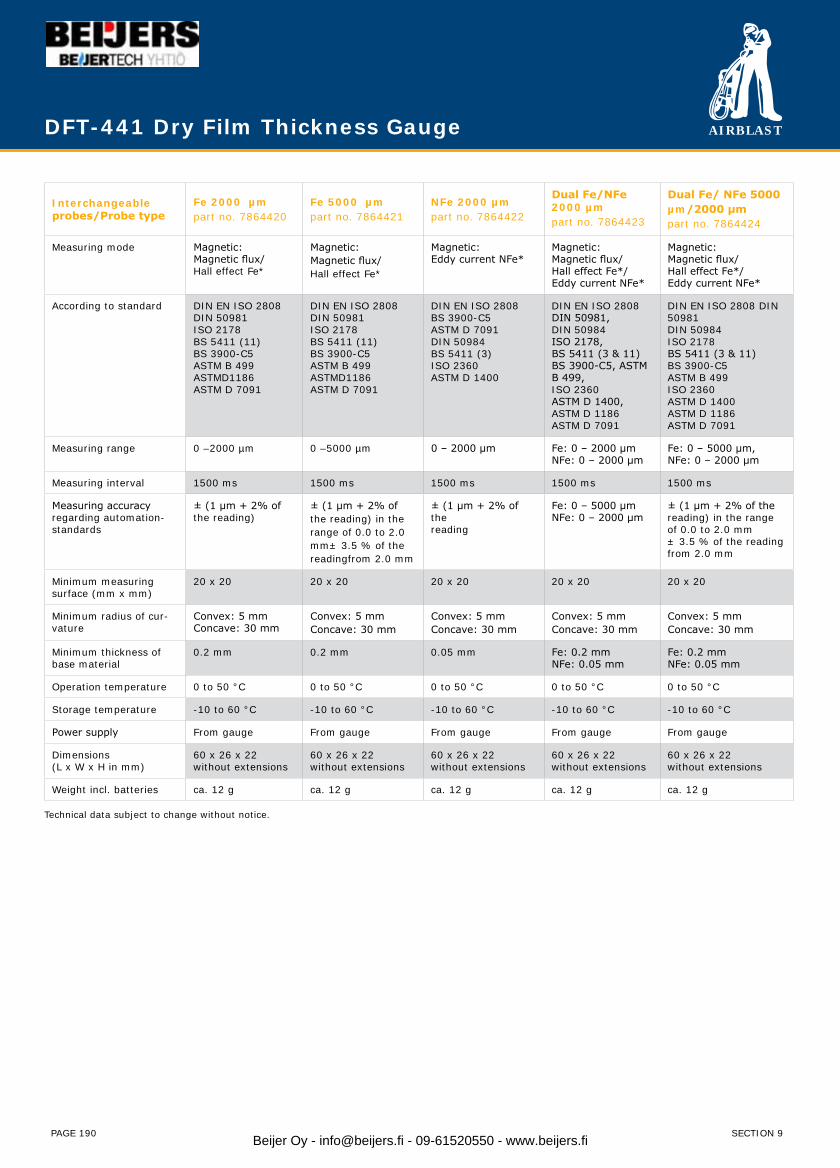
AIRBLAST
PAGE 190
Interchangeable probes/Probe type
Fe 2000 µmpart no. 7864420
Fe 5000 µmpart no. 7864421
NFe 2000 µmpart no. 7864422
Dual Fe/NFe 2000 µmpart no. 7864423
Dual Fe/ NFe 5000 µm/2000 µmpart no. 7864424
Measuring mode Magnetic:Magnetic flux/Hall effect Fe*
Magnetic:Magnetic flux/Hall effect Fe*
Magnetic:Eddy current NFe*
Magnetic:Magnetic flux/Hall effect Fe*/Eddy current NFe*
Magnetic:Magnetic flux/Hall effect Fe*/Eddy current NFe*
According to standard DIN EN ISO 2808DIN 50981ISO 2178BS 5411 (11)BS 3900-C5ASTM B 499ASTMD1186ASTM D 7091
DIN EN ISO 2808DIN 50981ISO 2178BS 5411 (11)BS 3900-C5ASTM B 499ASTMD1186ASTM D 7091
DIN EN ISO 2808BS 3900-C5ASTM D 7091DIN 50984BS 5411 (3)ISO 2360ASTM D 1400
DIN EN ISO 2808 DIN 50981,DIN 50984ISO 2178,BS 5411 (3 & 11)BS 3900-C5, ASTM B 499,ISO 2360ASTM D 1400,ASTM D 1186ASTM D 7091
DIN EN ISO 2808 DIN 50981DIN 50984ISO 2178BS 5411 (3 & 11) BS 3900-C5ASTM B 499ISO 2360ASTM D 1400ASTM D 1186ASTM D 7091
Measuring range 0 –2000 µm 0 –5000 µm 0 – 2000 μm Fe: 0 – 2000 μmNFe: 0 – 2000 μm
Fe: 0 – 5000 μm,NFe: 0 – 2000 μm
Measuring interval 1500 ms 1500 ms 1500 ms 1500 ms 1500 ms
Measuring accuracy regarding automation-standards
± (1 µm + 2% of the reading)
± (1 µm + 2% of the reading) in the range of 0.0 to 2.0 mm± 3.5 % of the readingfrom 2.0 mm
± (1 μm + 2% of thereading
Fe: 0 – 5000 μmNFe: 0 – 2000 μm
± (1 μm + 2% of thereading) in the rangeof 0.0 to 2.0 mm± 3.5 % of the reading from 2.0 mm
Minimum measuring surface (mm x mm)
20 x 20 20 x 20 20 x 20 20 x 20 20 x 20
Minimum radius of cur-vature
Convex: 5 mmConcave: 30 mm
Convex: 5 mmConcave: 30 mm
Convex: 5 mmConcave: 30 mm
Convex: 5 mmConcave: 30 mm
Convex: 5 mmConcave: 30 mm
Minimum thickness of base material
0.2 mm 0.2 mm 0.05 mm Fe: 0.2 mmNFe: 0.05 mm
Fe: 0.2 mmNFe: 0.05 mm
Operation temperature 0 to 50 °C 0 to 50 °C 0 to 50 °C 0 to 50 °C 0 to 50 °C
Storage temperature -10 to 60 °C -10 to 60 °C -10 to 60 °C -10 to 60 °C -10 to 60 °C
Power supply From gauge From gauge From gauge From gauge From gauge
Dimensions(L x W x H in mm)
60 x 26 x 22without extensions
60 x 26 x 22without extensions
60 x 26 x 22without extensions
60 x 26 x 22without extensions
60 x 26 x 22without extensions
Weight incl. batteries ca. 12 g ca. 12 g ca. 12 g ca. 12 g ca. 12 g
Technical data subject to change without notice.
DFT-441 Dry Film Thickness Gauge
SECTION 9Beijer Oy - [email protected] - 09-61520550 - www.beijers.fi
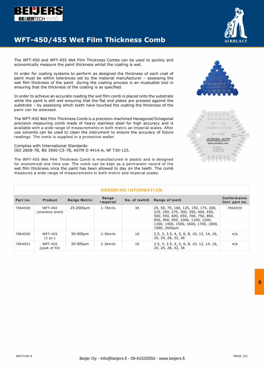
AIRBLAST
PAGE 191
The WFT-450 and WFT-455 Wet Film Thickness Combs can be used to quickly and economically measure the paint thickness whilst the coating is wet.
In order for coating systems to perform as designed the thickness of each coat of paint must be within tolerances set by the material manufacturer – assessing the wet film thickness of the paint during the coating process is an invaluable tool in ensuring that the thickness of the coating is as specified.
In order to achieve an accurate reading the wet film comb is placed onto the substrate while the paint is still wet ensuring that the flat end plates are pressed against the substrate – by assessing which teeth have touched the coating the thickness of the paint can be assessed.
The WFT-450 Wet Film Thickness Comb is a precision machined Hexagonal/Octagonal precision measuring comb made of heavy stainless steel for high accuracy and is available with a wide range of measurements in both metric an imperial scales. After use solvents can be used to clean the instrument to ensure the accuracy of future readings. The comb is supplied in a protective wallet.
Complies with International Standards:ISO 2808-7B, BS 3900-C5-7B, ASTM D 4414-A, NF T30-125.
The WFT-455 Wet Film Thickness Comb is manufactured in plastic and is designed for economical one time use. The comb can be kept as a permanent record of the wet film thickness once the paint has been allowed to day on the teeth. The comb measures a wide range of measurements in both metric and imperial scales.
ORDERING INFORMATION
Part no. Product Range Metric RangeImperial No. of teehth Range of teeth Conformance
Cert. part no.
7864500 WFT-450(stainless steel)
25-2000μm 1-78mils 36 25, 50, 75, 100, 125, 150, 175, 200, 225, 250, 275, 300, 350, 400, 450, 500, 550, 600, 650, 700, 750, 800, 850, 900, 950, 1000, 1100, 1200, 1300, 1400, 1500, 1600, 1700, 1800, 1900, 2000μm
7864020
7864550 WFT-455(1 pc.)
50-900μm 2-36mils 18 2.5, 3, 3.5, 4, 5, 6, 8, 10, 12, 14, 16, 20, 24, 28, 32, 36
n/a
7864551 WFT-455(pack of 50)
50-900μm 2-36mils 18 2.5, 3, 3.5, 4, 5, 6, 8, 10, 12, 14, 16, 20, 24, 28, 32, 36
n/a
WFT-450/455 Wet Film Thickness Comb
9
SECTION 9 Beijer Oy - [email protected] - 09-61520550 - www.beijers.fi

AIRBLAST
PAGE 192
The HAT-500 is a reliable method of testing the adhesion bond strength of a dry coating onto the substrate to which it is applied.
Correct adhesion is critical in ensuring that a paint system will perform as intended by the manufacturer. Insufficient adhesion can indicate incorrect substrate preparation or paint application.
To measure the adhesion a dolly is glued onto the painted substrate, a force is applied onto the center of the dolly by a hydraulically loaded pin, the maximum force applied is recorded on the pressure gauge by the reset needle. Should the dolly meet the minimum adhesion required it can be removed without disturbing the coating by using the heated dolly remover. Should the pressure overcome the adhesion of the dolly onto the surface the pressure will be recorded on the gauge. Dollies can be glued in place and left indefinitely as part of a scheduled maintenance programme.
The pressure gauge is swivel mounted to allow testing in any position and the flexible mid-section allows easy access. Adhesion on the internal and external surfaces of pipes can be tested using curved dollies.
The HAT-500 is supplied in a hard plastic foam filled carry case complete with 5 flat dollies, adhesive, dolly remover.
Complies with International Standards:ISO 16276-1, ISO 4624, ASTM D 4541, NF T30-606.
ORDERING INFORMATION
Part no. Head Type Operation Range PSI Operation Range MPa Accuracy Cal CertPart no.
7865000 HAT-500 - Standard 0-2600 PSI 0-18 ±1% 7865005
7865001 HAT-500 - Right Angle 0-2600 PSI 0-18 ±1% 7865005
HAT-500 Hydraulic Adhesion Tester
SECTION 9Beijer Oy - [email protected] - 09-61520550 - www.beijers.fi

AIRBLAST
PAGE 193
ACCESSORIES
Part no. Description Pipe Size Metric
Pipe SizeImperial Use with HAT-500 model Information
7865020 HAT-500 Concave Dolly 51mm 2” 7865000 / 7865001 For external pipe testing
7865021 HAT-500 Concave Dolly 76mm 3” 7865000 / 7865001
7865022 HAT-500 Concave Dolly 102mm 4” 7865000 / 7865001
7865023 HAT-500 Concave Dolly 152mm 6” 7865000 / 7865001
7865024 HAT-500 Concave Dolly 203mm 8” 7865000 / 7865001
7865025 HAT-500 Concave Dolly 254mm 10” 7865000 / 7865001
7865026 HAT-500 Concave Dolly 305mm 12” 7865000 / 7865001
7865027 HAT-500 Concave Dolly 356mm 14” 7865000 / 7865001
7865028 HAT-500 Concave Dolly 406mm 16” 7865000 / 7865001
7865029 HAT-500 Concave Dolly 457mm 18” 7865000 / 7865001
7865030 HAT-500 Concave Dolly 508mm 20” 7865000 / 7865001
7865031 HAT-500 Concave Dolly 610mm 24” 7865000 / 7865001
7865032 HAT-500 Concave Dolly 762mm 30” 7865000 / 7865001
7865033 HAT-500 Concave Dolly 914mm 36” 7865000 / 7865001
7865034 HAT-500 Convex Dolly 152mm 6” 7865001
7865035 HAT-500 Convex Dolly 203mm 8” 7865001 For internal pipe testing
7865036 HAT-500 Convex Dolly 254mm 10” 7865001
7865037 HAT-500 Convex Dolly 305mm 12” 7865000 / 7865001
7865038 HAT-500 Convex Dolly 356mm 14” 7865000 / 7865001
7865039 HAT-500 Convex Dolly 406mm 16” 7865000 / 7865001
7865040 HAT-500 Convex Dolly 457mm 18” 7865000 / 7865001
7865041 HAT-500 Convex Dolly 508mm 20” 7865000 / 7865001
7865042 HAT-500 Convex Dolly 610mm 24” 7865000 / 7865001
7865043 HAT-500 Convex Dolly 762mm 30” 7865000 / 7865001
7865044 HAT-500 Convex Dolly 914mm 36” 7865000 / 7865001
7865045 HAT-500 Flat Dolly 7865000 / 7865001 For sustrate testing
SPARE PARTSPart no. Description
7865046 Adhesive
7865047 Spare dolly plug
7865048 Heated dolly remover
HAT-500 Hydraulic Adhesion Tester
9
SECTION 9 Beijer Oy - [email protected] - 09-61520550 - www.beijers.fi
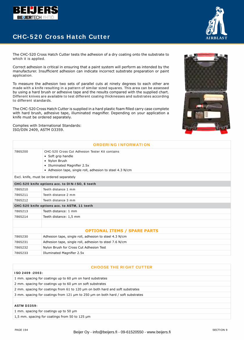
AIRBLAST
PAGE 194
The CHC-520 Cross Hatch Cutter tests the adhesion of a dry coating onto the substrate to which it is applied.
Correct adhesion is critical in ensuring that a paint system will perform as intended by the manufacturer. Insufficient adhesion can indicate incorrect substrate preparation or paint application.
To measure the adhesion two sets of parallel cuts at ninety degrees to each other are made with a knife resulting in a pattern of similar sized squares. This area can be assessed by using a hard brush or adhesive tape and the results compared with the supplied chart. Different knives are available to test different coating thicknesses and substrates according to different standards.
The CHC-520 Cross Hatch Cutter is supplied in a hard plastic foam filled carry case complete with hard brush, adhesive tape, illuminated magnifier. Depending on your application a knife must be ordered separately.
Complies with International Standards:ISO/DIN 2409, ASTM D3359.
ORDERING INFORMATION7865200 CHC-520 Cross Cut Adhesion Tester Kit contains
• Soft grip handle• Nylon Brush• Illuminated Magnifier 2.5x• Adhesion tape, single roll, adhesion to steel 4.3 N/cm
Excl. knife, must be ordered separately
CHC-520 knife options acc. to DIN-ISO, 6 teeth
7865210 Teeth distance 1 mm
7865211 Teeth distance 2 mm
7865212 Teeth distance 3 mm
CHC-520 knife options acc. to ASTM, 11 teeth
7865213 Teeth distance: 1 mm
7865214 Teeth distance: 1,5 mm
OPTIONAL ITEMS / SPARE PARTS7865230 Adhesion tape, single roll, adhesion to steel 4.3 N/cm
7865231 Adhesion tape, single roll, adhesion to steel 7.6 N/cm
7865232 Nylon Brush for Cross Cut Adhesion Test
7865233 Illuminated Magnifier 2.5x
CHOOSE THE RIGHT CUTTERISO 2409 :2003:
1 mm. spacing for coatings up to 60 μm on hard substrates
2 mm. spacing for coatings up to 60 μm on soft substrates
2 mm. spacing for coatings from 61 to 120 μm on both hard and soft substrates
3 mm. spacing for coatings from 121 μm to 250 μm on both hard / soft substrates
ASTM D3359:
1 mm. spacing for coatings up to 50 μm
1,5 mm. spacing for coatings from 50 to 125 μm
CHC-520 Cross Hatch Cutter
SECTION 9Beijer Oy - [email protected] - 09-61520550 - www.beijers.fi

AIRBLAST
PAGE 195
The HOD-600 Holiday Tester is used to test the integrity of a coated surface by identifying pin holes and flaws in the coating.
Pin holes or flaws in the coating may lead to premature failure of the coating – early identification allows for corrective action to be taken.
The HOD-600 Holiday Tester identifies pin holes and flaws in the coating by passing a voltage through a brush electrode which is moved over the coated surface – the voltage will spark through a pin hole or flaw to the substrate identifying the area for closer inspection. Upon identification of a pin hole or flaw an audible alarm will sound and a red indicator will flash on the unit. The application of the test is safe and does not cause burn marks or damage to the coating due to the test voltage being of high impedance.
ORDERING INFORMATION
Part no. Range Approx. maximum test thickness Resolution Accuracy Cal CertPart no.
7866000 HOD-600 - 0.5-6kV 1500μm (60mils) 0.01kV ±1% 7866005
7866001 HOD-600 - 1-20kV 5000μm (200mils) 0.1kV ±1% 7866005
7866002 HOD-600 - 1-30kV 7500μm (300mils) 0.1kV ±1% 7866005
The HOD-600 is supplied with a European style plug, other plug options available upon request.
HOD-600 DC Holiday Tester
The HOD-600 Holiday Tester can be carried by the operator using the neck strap provided due to its light weight and portable design.
The HOD-600 Holiday Tester is supplied in a hard plastic foam filled carry case complete with high voltage probe, brush electrode, earthing cable, and neck strap.
Complies with International Standards: ISO 2746, BS 1344-11, ASTM G 6, ASTM G 62, ASTM D4787, ASTM D5162, NACE RP 04901, NACE RP 0274, NACE RP 0188, JIS G3491, JIS G3492, AS 3894.1, EN14430, ANSI/AWWA C 213.
A calibration certificate traceable to UKAS is available as a cost option upon request.
SECTION 9
9
Beijer Oy - [email protected] - 09-61520550 - www.beijers.fi

AIRBLAST
PAGE 196
ACCESSORIES
Part no. Product Size Metric SizeImperial
Extension Size Information
7866030 Extension rod 500mm 20” To extend electrodes for applications where a long reach is required.7866031 Extension rod 1000mm 40”
7866040 Broad Brush 45° Angle 200mm 8” 200mm / 8” Brass-filled Brushes for the testing of coatings on large flat areas.7866041 Broad Brush 45° Angle 500mm 20” 200mm / 8”
7866050 Conductive Rubber 180° In Line 200mm 8” 200mm / 8” Conductive Rubber Electrodes for the testing of coatings on large flat areas.7866051 Conductive Rubber 180° In Line 450mm 18” 200mm / 8”
7866060 Circular Brush and Assembly 51mm 2” 200mm / 8” Conductive Rubber Electrodes for the testing of coatings on large flat areas.
All Brushes come complete with theconnector assembly.
7866061 Circular Brush and Assembly 76mm 3” 200mm / 8”
7866062 Circular Brush and Assembly 102mm 4” 200mm / 8”
7866063 Circular Brush and Assembly 152mm 6” 200mm / 8”
7866064 Circular Brush and Assembly 203mm 8” 200mm / 8”
7866065 Circular Brush and Assembly 254mm 10” 200mm / 8”
7866066 Circular Brush and Assembly 305mm 12” 200mm / 8”
7866070 Rolling Spring 102mm 4” Order SA490 3/4” phosphor bronze Rolling Spring for the testing of coatings on the external diameter of pipes.
All Rolling Springs require the 7866084 Rolling Spring Connector Assembly.One assembly can be used onmultiple Rolling Springs.
The 7866085 Rolling Spring PusherAssembly is suitable for largerRolling Springs, to assist the travel of the spring along the pipe.
7866071 Rolling Spring 152mm 6” Order SA490
7866072 Rolling Spring 203mm 8” Order SA490
7866073 Rolling Spring 254mm 10” Order SA490
7866074 Rolling Spring 305mm 12” Order SA490
7866075 Rolling Spring 356mm 14” Order SA490
7866076 Rolling Spring 406mm 16” Order SA490
7866077 Rolling Spring 457mm 18” Order SA490
7866078 Rolling Spring 508mm 20” Order SA490
7866079 Rolling Spring 610mm 24” Order SA490
7866080 Rolling Spring 762mm 30” Order SA490
7866081 Rolling Spring 914mm 36” Order SA490
7866082 Rolling Spring 1067mm 42” Order SA490
7866083 Rolling Spring 1220mm 48” Order SA490
7866084 Rolling Spring Connector Assy 200mm / 8”
7866085 Rolling Spring Pusher Assembly 200mm / 8”
HOD-600 DC Holiday Tester
SECTION 9Beijer Oy - [email protected] - 09-61520550 - www.beijers.fi
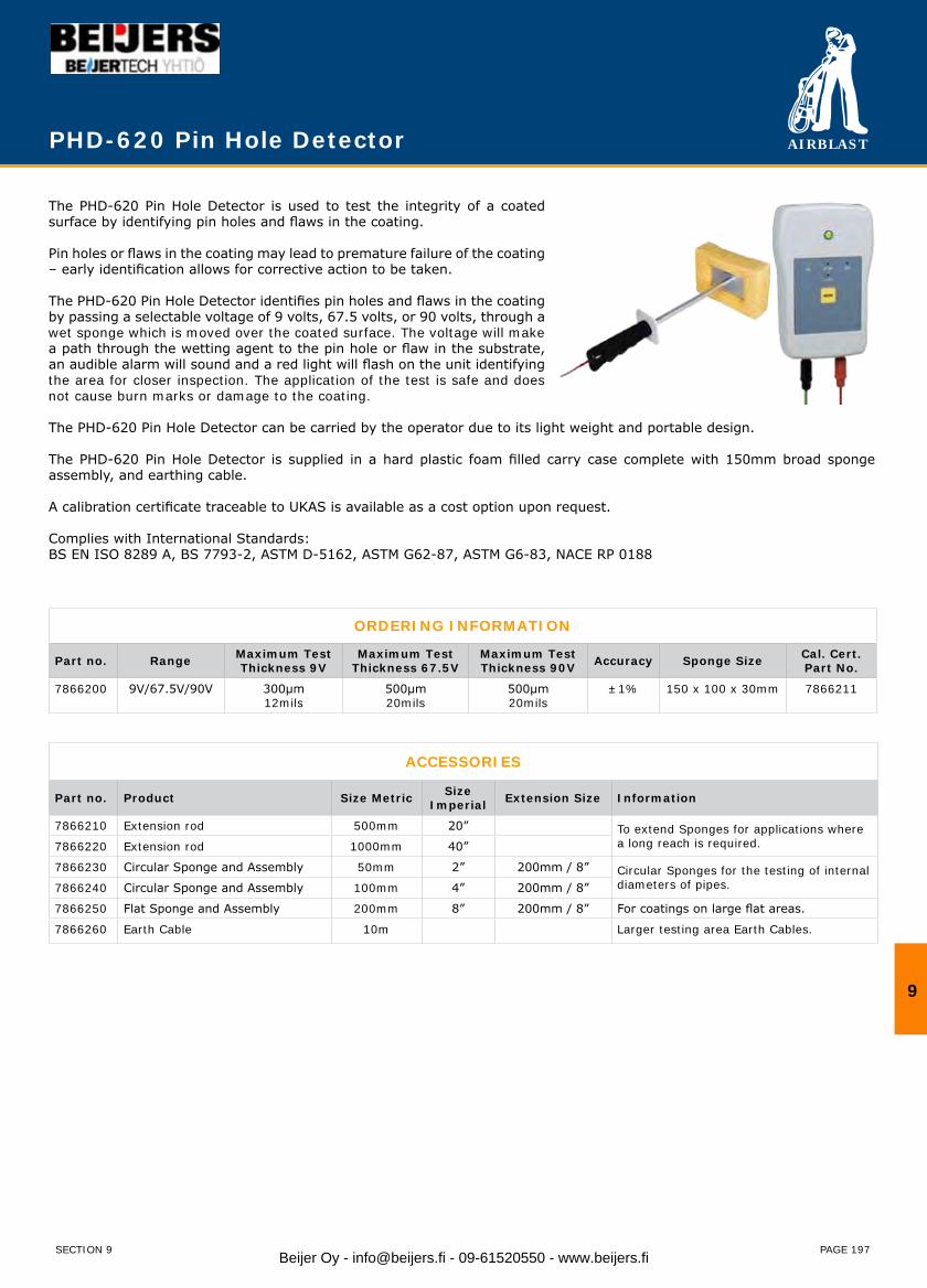
AIRBLAST
PAGE 197
The PHD-620 Pin Hole Detector is used to test the integrity of a coated surface by identifying pin holes and flaws in the coating.
Pin holes or flaws in the coating may lead to premature failure of the coating – early identification allows for corrective action to be taken.
The PHD-620 Pin Hole Detector identifies pin holes and flaws in the coating by passing a selectable voltage of 9 volts, 67.5 volts, or 90 volts, through a wet sponge which is moved over the coated surface. The voltage will make a path through the wetting agent to the pin hole or flaw in the substrate, an audible alarm will sound and a red light will flash on the unit identifying the area for closer inspection. The application of the test is safe and does not cause burn marks or damage to the coating.
The PHD-620 Pin Hole Detector can be carried by the operator due to its light weight and portable design.
The PHD-620 Pin Hole Detector is supplied in a hard plastic foam filled carry case complete with 150mm broad sponge assembly, and earthing cable.
A calibration certificate traceable to UKAS is available as a cost option upon request. Complies with International Standards:BS EN ISO 8289 A, BS 7793-2, ASTM D-5162, ASTM G62-87, ASTM G6-83, NACE RP 0188
PHD-620 Pin Hole Detector
ORDERING INFORMATION
Part no. Range Maximum Test Thickness 9V
Maximum Test Thickness 67.5V
Maximum Test Thickness 90V Accuracy Sponge Size Cal. Cert.
Part No.
7866200 9V/67.5V/90V 300μm12mils
500μm20mils
500μm20mils
±1% 150 x 100 x 30mm 7866211
ACCESSORIES
Part no. Product Size Metric SizeImperial Extension Size Information
7866210 Extension rod 500mm 20” To extend Sponges for applications where a long reach is required.7866220 Extension rod 1000mm 40”
7866230 Circular Sponge and Assembly 50mm 2” 200mm / 8” Circular Sponges for the testing of internal diameters of pipes.7866240 Circular Sponge and Assembly 100mm 4” 200mm / 8”
7866250 Flat Sponge and Assembly 200mm 8” 200mm / 8” For coatings on large flat areas.
7866260 Earth Cable 10m Larger testing area Earth Cables.
9
SECTION 9 Beijer Oy - [email protected] - 09-61520550 - www.beijers.fi

AIRBLAST
PAGE 215
Subject Page
Blasting - Nozzle Pressure/Diameter/Service Life/Air Volume 216
Blasting - Nozzle Selector Type Guide / Air Line Sizes 217
Blasting - Steel Surface Finish Standards 218
Blasting - Abrasive Blast Performance Guide 219
Blasting - Checking Compressed Air Quality 220
Painting - Paint Application Tables 221
Painting - Paint Application Information 222
Inspection - Surface Profile 223
Inspection - Surface Cleanliness Factors 224
Inspection - Climatic Conditions for Safe Painting 226
Abrasives - Abrasive Characteristic Comparison 227
Conversion factors 228
Section 11 - Tips & Tricks
11
SECTION 11 Beijer Oy - [email protected] - 09-61520550 - www.beijers.fi
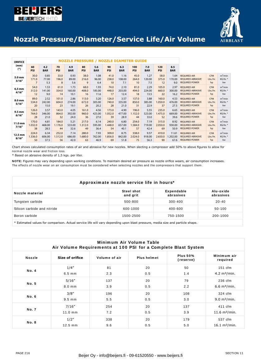
AIRBLAST
PAGE 216
Nozzle Pressure/Diameter/Service Life/Air Volume
ORIFICE(mm)
(“)
NOZZLE PRESSURE / NOZZLE DIAMETER GUIDE
60PSI
4.2BAR
70PSI
4.9BAR
80PSI
5.6BAR
90PSI
6.3BAR
100PSI
7.0BAR
120PSI
8.5BAR
5.0 mm3/16”
30.0171.0
7
0.8577.00
5.3
33.0196.0
8
0.9389.00
5.6
38.0216.0
9
1.0896.00
6.4
41.0238.0
10
1.16108.00
7.1
45.0264.0
10
1.27120.00
7.5
58.0375.0
12
1.64170.00
9.0
REQUIRED AIR REQUIRED ABRASIVEREQUIRED POWER
CFMLbs./hr.
hp
m³/minKG/hr. *
kw
6,5 mm4/16”
54.0312.0
12
1.53141.00
9.0
61.0354.0
14
1.73160.00
10.1
68.0408.0
16
1.93185.00
11.6
74.0448.0
17
2.10203.00
12.4
81.0494.0
18
2.29224.00
13.5
105.0660.0
22
2.97300.00
16.2
REQUIRED AIRREQUIRED ABRASIVEREQUIRED POWER
CFMLbs./hr.
hp
m³/minKG/hr. *
kw
8.0 mm5/16”
89.0534.0
20
2.52242.00
15.0
101.0604.0
23
2.86274.00
19.1
113.0672.0
26
3.20305.00
20.2
126.0740.0
28
3.57335.00
21.0
137.0850.0
31
3.88385.00
22.9
160.01.050.0
37
4.53476.00
27.5
REQUIRED AIRREQUIRED ABRASIVEREQUIRED POWER
CFMLbs./hr.
hp
m³/minKG/hr. *
kw
9.5 mm6/16”
126.0764.0
28
3.57346.00
21.0
143.0864.0
32
4.05392.00
24.0
161.0960.0
36
4.56425.00
27.0
173.01.052.0
39
4.90477.00
28.9
196.01.152.0
44
5.55523.00
33.0
235.01.475.0
52
6.65669.00
39.6
REQUIRED AIRREQUIRED ABRASIVEREQUIRED POWER
CFMLbs./hr.
hp
m³/minKG/hr. *
kw
11.0 mm7/16”
170.01.032.0
38
4.81468.00
28.5
184.01.176.0
44
5.21533.00
32.6
217.01.312.0
49
6.14595.00
36.4
240.01.448.0
54
6.80657.00
40.1
254.01.584.0
57
7.19719.00
42.4
315.02.050.0
69
8.92930.00
50.9
REQUIRED AIRREQUIRED ABRASIVEREQUIRED POWER
CFMLbs./hr.
hp
m³/minKG/hr. *
kw
12.5 mm8/16”
224.01.336.0
50
6.34606.00
37.5
252.01.512.0
56
7.14686.00
42.0
280.01.680.0
63
7.93762.00
46.9
309.01.856.0
69
8.75842.00
51.8
338.02.024.0
75
9.57918.00
56.3
410.02.650.0
90
11.611.202.00
67.6
REQUIRED AIRREQUIRED ABRASIVEREQUIRED POWER
CFMLbs./hr.
hp
m³/minKG/hr. *
kw
Chart shows calculated consumption rates of air and abrasive for new nozzles. When slecting a compressor add 50% to above figures to allow for normal nozzle wear and friction loss. * Based on abrasive density of 1,5 kgs. per liter.
NOTE: Figures may vary depending upon working conditions. To maintain desired air pressure as nozzle orifice wears, air consumption increases. The effects of nozzle wear on air consumption must be considered when selecting nozzles and the compressors that support them.
Approximate nozzle service life in hours*
Nozzle material Steel shotand grit
Expendable abrasives
Alu-oxideabrasives
Tungsten carbide 500-800 300-400 20-40
Silicon carbide and nitride 600-1000 400-600 50-100
Boron carbide 1500-2500 750-1500 200-1000
* Estimated values for comparison. Actual service life will vary depending upon blast pressure, media size and particle shape.
Minimum Air Volume TableAir Volume Requirements at 100 PSI for a Complete Blast System
Nozzle Size of orifice Volume of air Plus helmet Plus 50% (reserve)
Minimum airrequired
No. 41/4”
6.5 mm
81
2.3
20
0.5
50
1.4
151 cfm
4.2 m³/min.
No. 55/16”
8.0 mm
137
3.9
20
0.5
79
2.2
236 cfm
6.6 m³/min.
No. 63/8”
9.5 mm
196
5.5
20
0.5
108
3.0
324 cfm
9.0 m³/min.
No. 77/16”
11.0 mm
254
7.2
20
0.5
137
3.9
411 cfm
11.6 m³/min.
No. 81/2”
12.5 mm
338
9.6
20
0.5
179
5.0
537 cfm
16.1 m³/min.
SECTION 11Beijer Oy - [email protected] - 09-61520550 - www.beijers.fi
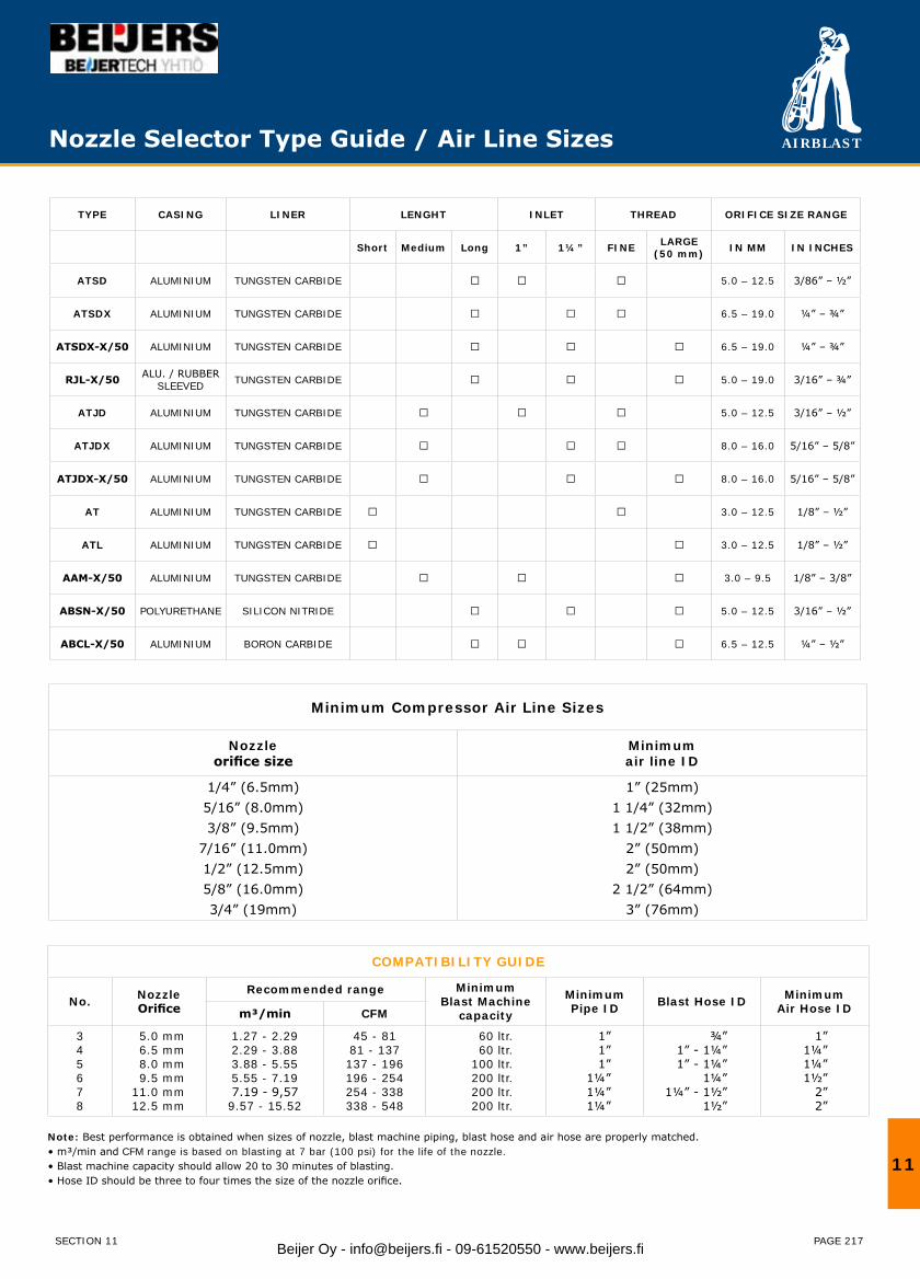
AIRBLAST
PAGE 217
TYPE CASING LINER LENGHT INLET THREAD ORIFICE SIZE RANGE
Short Medium Long 1” 1¼” FINE LARGE (50 mm) IN MM IN INCHES
ATSD ALUMINIUM TUNGSTEN CARBIDE 5.0 – 12.5 3/86” – ½”
ATSDX ALUMINIUM TUNGSTEN CARBIDE 6.5 – 19.0 ¼” – ¾”
ATSDX-X/50 ALUMINIUM TUNGSTEN CARBIDE 6.5 – 19.0 ¼” – ¾”
RJL-X/50 ALU. / RUBBER SLEEVED TUNGSTEN CARBIDE 5.0 – 19.0 3/16” – ¾”
ATJD ALUMINIUM TUNGSTEN CARBIDE 5.0 – 12.5 3/16” – ½”
ATJDX ALUMINIUM TUNGSTEN CARBIDE 8.0 – 16.0 5/16” – 5/8”
ATJDX-X/50 ALUMINIUM TUNGSTEN CARBIDE 8.0 – 16.0 5/16” – 5/8”
AT ALUMINIUM TUNGSTEN CARBIDE 3.0 – 12.5 1/8” – ½”
ATL ALUMINIUM TUNGSTEN CARBIDE 3.0 – 12.5 1/8” – ½”
AAM-X/50 ALUMINIUM TUNGSTEN CARBIDE 3.0 – 9.5 1/8” – 3/8”
ABSN-X/50 POLYURETHANE SILICON NITRIDE 5.0 – 12.5 3/16” – ½”
ABCL-X/50 ALUMINIUM BORON CARBIDE 6.5 – 12.5 ¼” – ½”
Nozzle Selector Type Guide / Air Line Sizes
Minimum Compressor Air Line Sizes
Nozzleorifice size
Minimumair line ID
1/4” (6.5mm)5/16” (8.0mm)3/8” (9.5mm)
7/16” (11.0mm)1/2” (12.5mm)5/8” (16.0mm)3/4” (19mm)
1” (25mm)1 1/4” (32mm)1 1/2” (38mm)
2” (50mm)2” (50mm)
2 1/2” (64mm)3” (76mm)
COMPATIBILITY GUIDE
No. Nozzle Orifice
Recommended range MinimumBlast Machine
capacity
Minimum Pipe ID Blast Hose ID Minimum
Air Hose IDm³/min CFM
345678
5.0 mm6.5 mm8.0 mm9.5 mm
11.0 mm12.5 mm
1.27 - 2.292.29 - 3.883.88 - 5.555.55 - 7.197.19 - 9,579.57 - 15.52
45 - 8181 - 137137 - 196196 - 254254 - 338338 - 548
60 ltr.60 ltr.
100 ltr.200 ltr.200 ltr.200 ltr.
1”1”1”
1¼”1¼”1¼”
¾”1” - 1¼”1” - 1¼”
1¼”1¼” - 1½”
1½”
1”1¼”1¼”1½”
2”2”
Note: Best performance is obtained when sizes of nozzle, blast machine piping, blast hose and air hose are properly matched. • m³/min and CFM range is based on blasting at 7 bar (100 psi) for the life of the nozzle.• Blast machine capacity should allow 20 to 30 minutes of blasting.• Hose ID should be three to four times the size of the nozzle orifice.
11
SECTION 11 Beijer Oy - [email protected] - 09-61520550 - www.beijers.fi
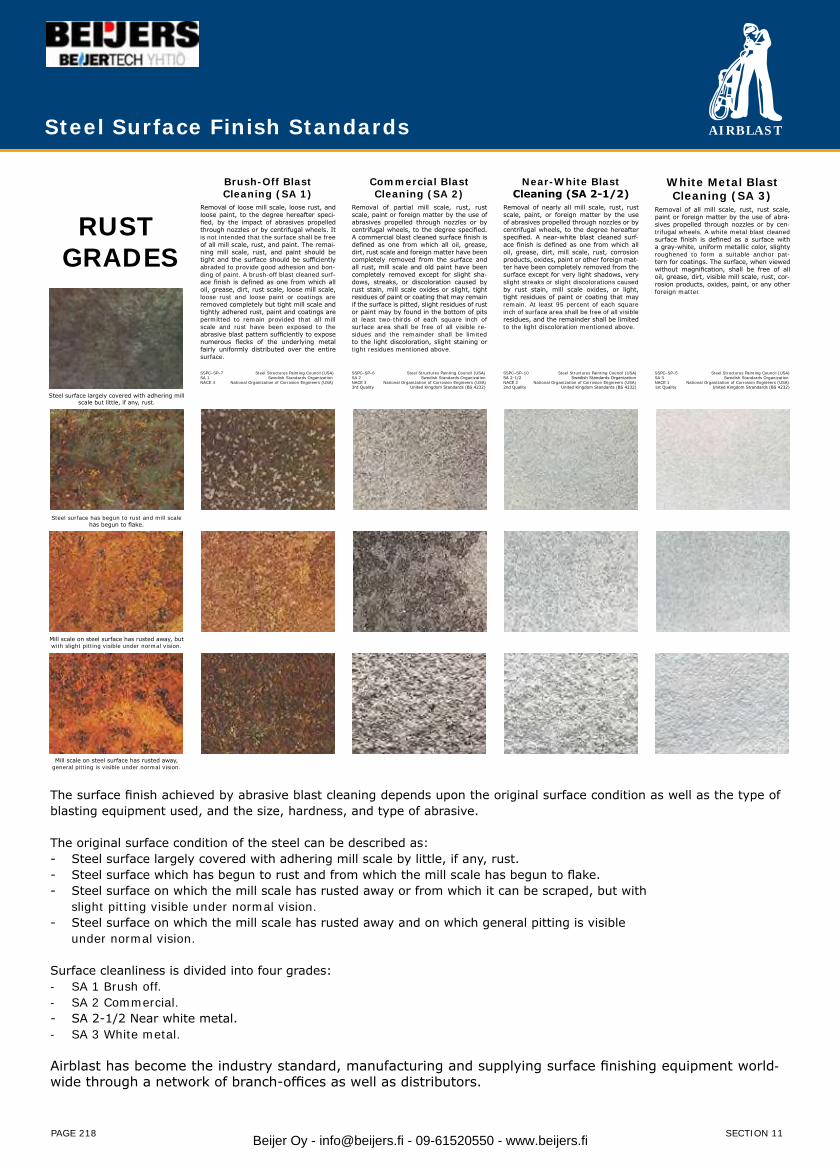
AIRBLAST
PAGE 218
Steel Surface Finish Standards
RUST GRADES
Brush-Off BlastCleaning (SA 1)
Removal of loose mill scale, loose rust, and loose paint, to the degree hereafter speci-fied, by the impact of abrasives propelled through nozzles or by centrifugal wheels. It is not intended that the surface shall be free of all mill scale, rust, and paint. The remai-ning mill scale, rust, and paint should be tight and the surface should be sufficiently abraded to provide good adhesion and bon-ding of paint. A brush-off blast cleaned surf-ace finish is defined as one from which all oil, grease, dirt, rust scale, loose mill scale, loose rust and loose paint or coatings are removed completely but tight mill scale and tightly adhered rust, paint and coatings are permitted to remain provided that all mill scale and rust have been exposed to the abrasive blast pattern sufficiently to expose numerous flecks of the underlying metal fairly uniformly distributed over the entire surface.
Commercial BlastCleaning (SA 2)
Removal of partial mill scale, rust, rust scale, paint or foreign matter by the use of abrasives propelled through nozzles or by centrifugal wheels, to the degree specified. A commercial blast cleaned surface finish is defined as one from which all oil, grease, dirt, rust scale and foreign matter have been completely removed from the surface and all rust, mill scale and old paint have been completely removed except for slight sha-dows, streaks, or discoloration caused by rust stain, mill scale oxides or slight, tight residues of paint or coating that may remain if the surface is pitted, slight residues of rust or paint may by found in the bottom of pits at least two-thirds of each square inch of surface area shall be free of all visible re-sidues and the remainder shall be limited to the light discoloration, slight staining or tight residues mentioned above.
Near-White BlastCleaning (SA 2-1/2)
Removal of nearly all mill scale, rust, rust scale, paint, or foreign matter by the use of abrasives propelled through nozzles or by centrifugal wheels, to the degree hereafter specified. A near-white blast cleaned surf-ace finish is defined as one from which all oil, grease, dirt, mill scale, rust, corrosion products, oxides, paint or other foreign mat-ter have been completely removed from the surface except for very light shadows, very slight streaks or slight discolorations caused by rust stain, mill scale oxides, or light, tight residues of paint or coating that may remain. At least 95 percent of each square inch of surface area shall be free of all visible residues, and the remainder shall be limited to the light discoloration mentioned above.
White Metal Blast Cleaning (SA 3)
Removal of all mill scale, rust, rust scale, paint or foreign matter by the use of abra-sives propelled through nozzles or by cen-trifugal wheels. A white metal blast cleaned surface finish is defined as a surface with a gray-white, uniform metallic color, slighty roughened to form a suitable anchor pat-tern for coatings. The surface, when viewed without magnification, shall be free of all oil, grease, dirt, visible mill scale, rust, cor-rosion products, oxides, paint, or any other foreign matter.
SSPC–SP–7 Steel Structures Painting Council (USA)SA 1 Swedish Standards OrganizationNACE 4 National Organization of Corrosion Engineers (USA)
SSPC–SP–6 Steel Structures Painting Council (USA)SA 2 Swedish Standards OrganizationNACE 3 National Organization of Corrosion Engineers (USA)3rd Quality United Kingdom Standards (BS 4232)
SSPC–SP–10 Steel Structures Painting Council (USA)SA 2-1/2 Swedish Standards OrganizationNACE 2 National Organization of Corrosion Engineers (USA)2nd Quality United Kingdom Standards (BS 4232)
SSPC–SP–5 Steel Structures Painting Council (USA)SA 3 Swedish Standards OrganizationNACE 1 National Organization of Corrosion Engineers (USA)1st Quality United Kingdom Strandards (BS 4232)
Steel surface largely covered with adhering mill scale but little, if any, rust.
Steel surface has begun to rust and mill scalehas begun to flake.
Mill scale on steel surface has rusted away, butwith slight pitting visible under normal vision.
Mill scale on steel surface has rusted away,general pitting is visible under normal vision.
The surface finish achieved by abrasive blast cleaning depends upon the original surface condition as well as the type of blasting equipment used, and the size, hardness, and type of abrasive.
The original surface condition of the steel can be described as:- Steel surface largely covered with adhering mill scale by little, if any, rust.- Steel surface which has begun to rust and from which the mill scale has begun to flake.- Steel surface on which the mill scale has rusted away or from which it can be scraped, but with slight pitting visible under normal vision.- Steel surface on which the mill scale has rusted away and on which general pitting is visible under normal vision.
Surface cleanliness is divided into four grades:- SA 1 Brush off.- SA 2 Commercial.- SA 2-1/2 Near white metal.- SA 3 White metal.
Airblast has become the industry standard, manufacturing and supplying surface finishing equipment world-wide through a network of branch-offices as well as distributors.
SECTION 11Beijer Oy - [email protected] - 09-61520550 - www.beijers.fi
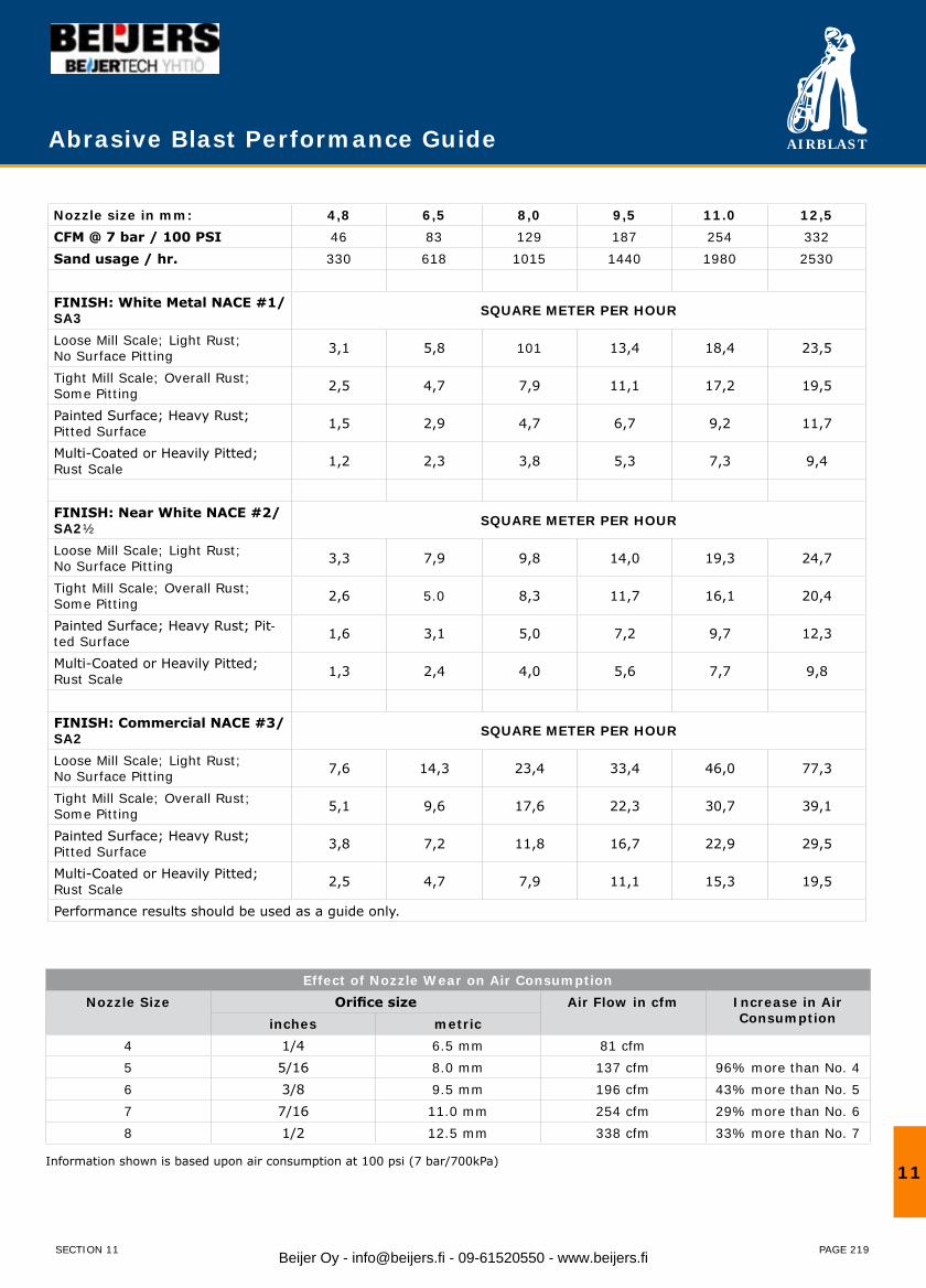
AIRBLAST
PAGE 219
Nozzle size in mm: 4,8 6,5 8,0 9,5 11.0 12,5CFM @ 7 bar / 100 PSI 46 83 129 187 254 332Sand usage / hr. 330 618 1015 1440 1980 2530
FINISH: White Metal NACE #1/SA3 SQUARE METER PER HOUR
Loose Mill Scale; Light Rust;No Surface Pitting 3,1 5,8 101 13,4 18,4 23,5
Tight Mill Scale; Overall Rust; Some Pitting 2,5 4,7 7,9 11,1 17,2 19,5
Painted Surface; Heavy Rust;Pitted Surface 1,5 2,9 4,7 6,7 9,2 11,7
Multi-Coated or Heavily Pitted; Rust Scale 1,2 2,3 3,8 5,3 7,3 9,4
FINISH: Near White NACE #2/SA2½ SQUARE METER PER HOUR
Loose Mill Scale; Light Rust;No Surface Pitting 3,3 7,9 9,8 14,0 19,3 24,7
Tight Mill Scale; Overall Rust; Some Pitting 2,6 5.0 8,3 11,7 16,1 20,4
Painted Surface; Heavy Rust; Pit-ted Surface 1,6 3,1 5,0 7,2 9,7 12,3
Multi-Coated or Heavily Pitted; Rust Scale 1,3 2,4 4,0 5,6 7,7 9,8
FINISH: Commercial NACE #3/SA2 SQUARE METER PER HOUR
Loose Mill Scale; Light Rust;No Surface Pitting 7,6 14,3 23,4 33,4 46,0 77,3
Tight Mill Scale; Overall Rust; Some Pitting 5,1 9,6 17,6 22,3 30,7 39,1
Painted Surface; Heavy Rust;Pitted Surface 3,8 7,2 11,8 16,7 22,9 29,5
Multi-Coated or Heavily Pitted; Rust Scale 2,5 4,7 7,9 11,1 15,3 19,5
Performance results should be used as a guide only.
Abrasive Blast Performance Guide
Effect of Nozzle Wear on Air ConsumptionNozzle Size Orifice size Air Flow in cfm Increase in Air
Consumptioninches metric4 1/4 6.5 mm 81 cfm5 5/16 8.0 mm 137 cfm 96% more than No. 46 3/8 9.5 mm 196 cfm 43% more than No. 57 7/16 11.0 mm 254 cfm 29% more than No. 68 1/2 12.5 mm 338 cfm 33% more than No. 7
Information shown is based upon air consumption at 100 psi (7 bar/700kPa)11
SECTION 11 Beijer Oy - [email protected] - 09-61520550 - www.beijers.fi
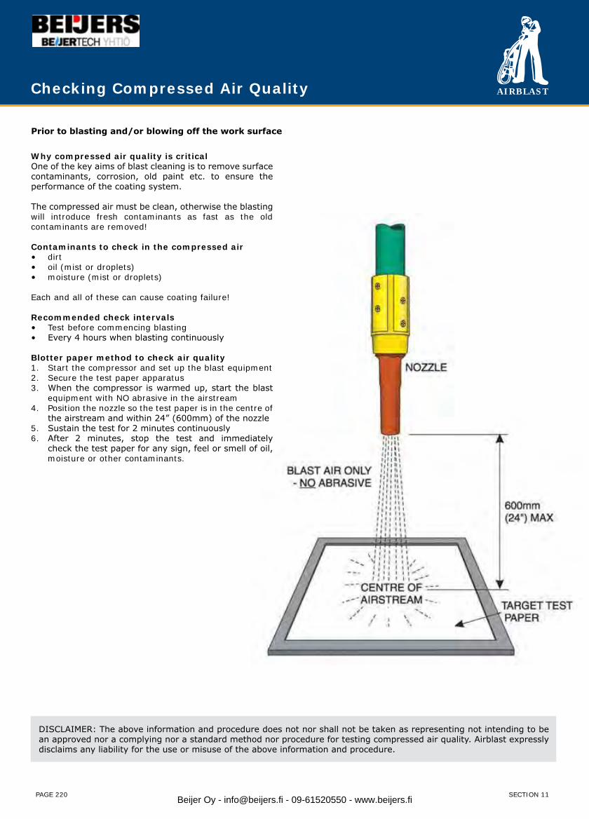
AIRBLAST
PAGE 220
Why compressed air quality is criticalOne of the key aims of blast cleaning is to remove surface contaminants, corrosion, old paint etc. to ensure the performance of the coating system.
The compressed air must be clean, otherwise the blasting will introduce fresh contaminants as fast as the old contaminants are removed!
Contaminants to check in the compressed airdirt• oil (mist or droplets)• moisture (mist or droplets)•
Each and all of these can cause coating failure!
Recommended check intervalsTest before commencing blasting• Every 4 hours when blasting continuously•
Blotter paper method to check air qualityStart the compressor and set up the blast equipment1. Secure the test paper apparatus2. When the compressor is warmed up, start the blast 3. equipment with NO abrasive in the airstreamPosition the nozzle so the test paper is in the centre of 4. the airstream and within 24” (600mm) of the nozzleSustain the test for 2 minutes continuously5. After 2 minutes, stop the test and immediately 6. check the test paper for any sign, feel or smell of oil, moisture or other contaminants.
Checking Compressed Air Quality
DISCLAIMER: The above information and procedure does not nor shall not be taken as representing not intending to be an approved nor a complying nor a standard method nor procedure for testing compressed air quality. Airblast expressly disclaims any liability for the use or misuse of the above information and procedure.
Prior to blasting and/or blowing off the work surface
SECTION 11Beijer Oy - [email protected] - 09-61520550 - www.beijers.fi
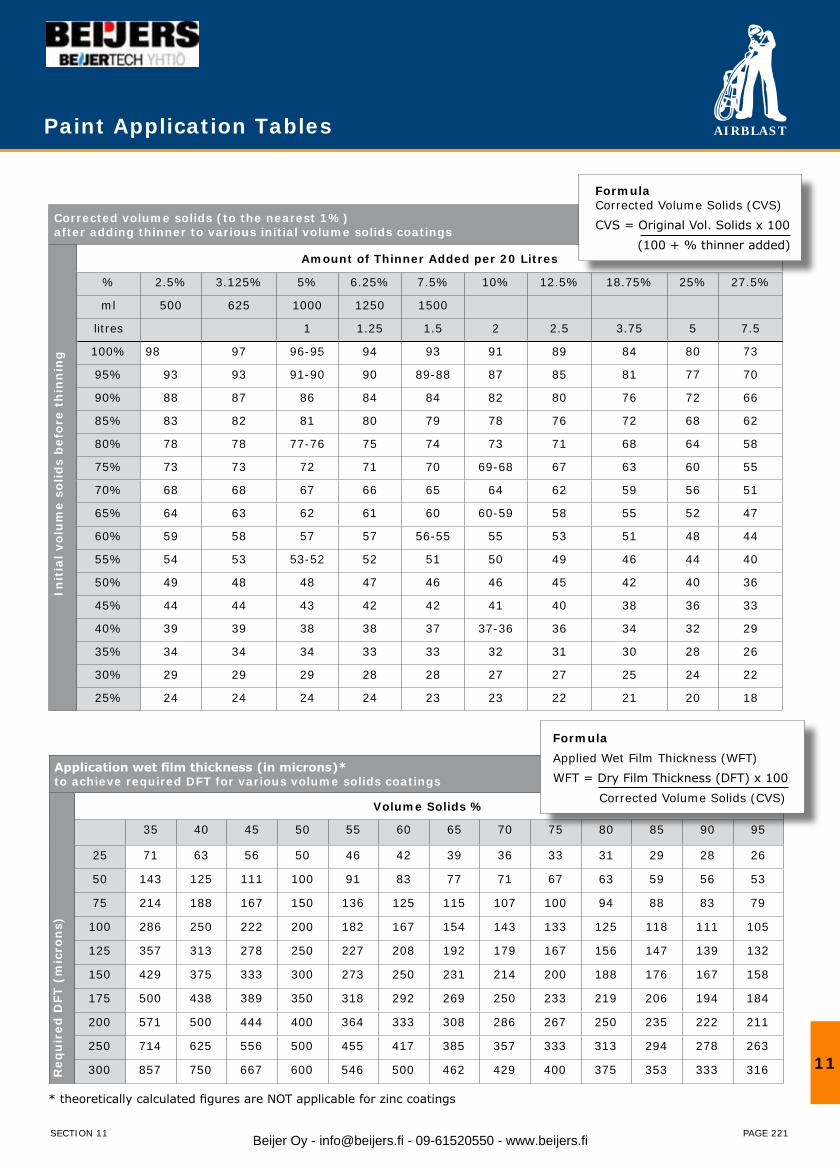
AIRBLAST
PAGE 221
Corrected volume solids (to the nearest 1%)after adding thinner to various initial volume solids coatings
Amount of Thinner Added per 20 Litres
% 2.5% 3.125% 5% 6.25% 7.5% 10% 12.5% 18.75% 25% 27.5%
ml 500 625 1000 1250 1500
litres 1 1.25 1.5 2 2.5 3.75 5 7.5
100% 98 97 96-95 94 93 91 89 84 80 73
95% 93 93 91-90 90 89-88 87 85 81 77 70
90% 88 87 86 84 84 82 80 76 72 66
85% 83 82 81 80 79 78 76 72 68 62
80% 78 78 77-76 75 74 73 71 68 64 58
75% 73 73 72 71 70 69-68 67 63 60 55
70% 68 68 67 66 65 64 62 59 56 51
65% 64 63 62 61 60 60-59 58 55 52 47
60% 59 58 57 57 56-55 55 53 51 48 44
55% 54 53 53-52 52 51 50 49 46 44 40
50% 49 48 48 47 46 46 45 42 40 36
45% 44 44 43 42 42 41 40 38 36 33
40% 39 39 38 38 37 37-36 36 34 32 29
35% 34 34 34 33 33 32 31 30 28 26
30% 29 29 29 28 28 27 27 25 24 22
25% 24 24 24 24 23 23 22 21 20 18
Init
ial v
olu
me
solid
s b
efor
e th
inn
ing
Paint Application Tables
Application wet film thickness (in microns)*to achieve required DFT for various volume solids coatings
Volume Solids %
35 40 45 50 55 60 65 70 75 80 85 90 95
25 71 63 56 50 46 42 39 36 33 31 29 28 26
50 143 125 111 100 91 83 77 71 67 63 59 56 53
75 214 188 167 150 136 125 115 107 100 94 88 83 79
100 286 250 222 200 182 167 154 143 133 125 118 111 105
125 357 313 278 250 227 208 192 179 167 156 147 139 132
150 429 375 333 300 273 250 231 214 200 188 176 167 158
175 500 438 389 350 318 292 269 250 233 219 206 194 184
200 571 500 444 400 364 333 308 286 267 250 235 222 211
250 714 625 556 500 455 417 385 357 333 313 294 278 263
300 857 750 667 600 546 500 462 429 400 375 353 333 316
* theoretically calculated figures are NOT applicable for zinc coatings
Req
uir
ed D
FT (
mic
ron
s)
FormulaCorrected Volume Solids (CVS)CVS = Original Vol. Solids x 100 (100 + % thinner added)
FormulaApplied Wet Film Thickness (WFT)WFT = Dry Film Thickness (DFT) x 100 Corrected Volume Solids (CVS)
11
SECTION 11 Beijer Oy - [email protected] - 09-61520550 - www.beijers.fi
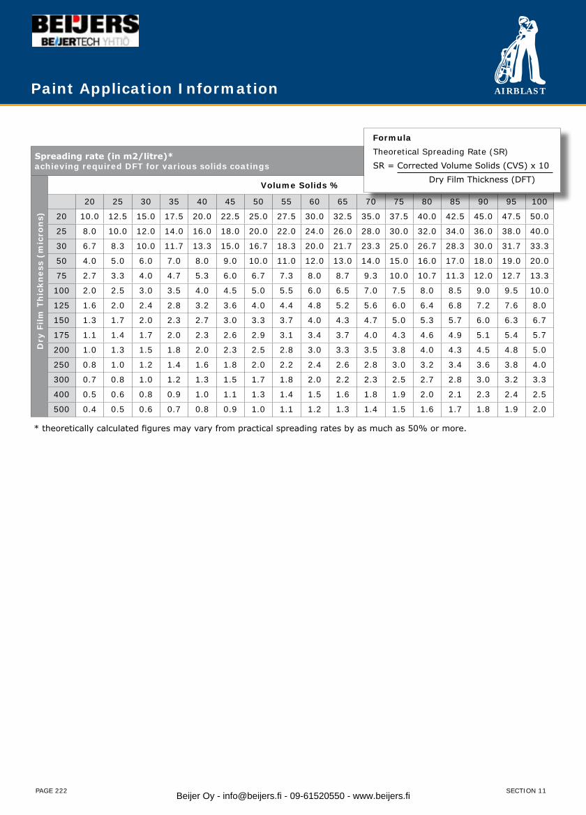
AIRBLAST
PAGE 222
Spreading rate (in m2/litre)*achieving required DFT for various solids coatings
Volume Solids %
20 25 30 35 40 45 50 55 60 65 70 75 80 85 90 95 100
20 10.0 12.5 15.0 17.5 20.0 22.5 25.0 27.5 30.0 32.5 35.0 37.5 40.0 42.5 45.0 47.5 50.0
25 8.0 10.0 12.0 14.0 16.0 18.0 20.0 22.0 24.0 26.0 28.0 30.0 32.0 34.0 36.0 38.0 40.0
30 6.7 8.3 10.0 11.7 13.3 15.0 16.7 18.3 20.0 21.7 23.3 25.0 26.7 28.3 30.0 31.7 33.3
50 4.0 5.0 6.0 7.0 8.0 9.0 10.0 11.0 12.0 13.0 14.0 15.0 16.0 17.0 18.0 19.0 20.0
75 2.7 3.3 4.0 4.7 5.3 6.0 6.7 7.3 8.0 8.7 9.3 10.0 10.7 11.3 12.0 12.7 13.3
100 2.0 2.5 3.0 3.5 4.0 4.5 5.0 5.5 6.0 6.5 7.0 7.5 8.0 8.5 9.0 9.5 10.0
125 1.6 2.0 2.4 2.8 3.2 3.6 4.0 4.4 4.8 5.2 5.6 6.0 6.4 6.8 7.2 7.6 8.0
150 1.3 1.7 2.0 2.3 2.7 3.0 3.3 3.7 4.0 4.3 4.7 5.0 5.3 5.7 6.0 6.3 6.7
175 1.1 1.4 1.7 2.0 2.3 2.6 2.9 3.1 3.4 3.7 4.0 4.3 4.6 4.9 5.1 5.4 5.7
200 1.0 1.3 1.5 1.8 2.0 2.3 2.5 2.8 3.0 3.3 3.5 3.8 4.0 4.3 4.5 4.8 5.0
250 0.8 1.0 1.2 1.4 1.6 1.8 2.0 2.2 2.4 2.6 2.8 3.0 3.2 3.4 3.6 3.8 4.0
300 0.7 0.8 1.0 1.2 1.3 1.5 1.7 1.8 2.0 2.2 2.3 2.5 2.7 2.8 3.0 3.2 3.3
400 0.5 0.6 0.8 0.9 1.0 1.1 1.3 1.4 1.5 1.6 1.8 1.9 2.0 2.1 2.3 2.4 2.5
500 0.4 0.5 0.6 0.7 0.8 0.9 1.0 1.1 1.2 1.3 1.4 1.5 1.6 1.7 1.8 1.9 2.0
* theoretically calculated figures may vary from practical spreading rates by as much as 50% or more.
Dry
Film
Th
ickn
ess
(mic
ron
s)
Paint Application Information
FormulaTheoretical Spreading Rate (SR)SR = Corrected Volume Solids (CVS) x 10 Dry Film Thickness (DFT)
SECTION 11Beijer Oy - [email protected] - 09-61520550 - www.beijers.fi

AIRBLAST
PAGE 223
FormulaTheoretical Spreading Rate (SR)SR = Corrected Volume Solids (CVS) x 10 Dry Film Thickness (DFT)
Surface Profile
Understanding surface profile
In the blast cleaning process, grains of abrasive are propelled with great force and energy at the work surface. Upon impact, the grains ‘dig’ into and then rebound out and off the surface leaving a rugged, miniature ‘mountain – and – valley’ finish.
This surface roughness/etch/texture is the surface profile.
Surface profile is critical to coating performance by1) increasing the surface area2) providing a ‘key/tooth/anchor pattern’ for the coating to lock and adhere to
The difference between surface profile and class of blastSurface profile is concerned with the ‘shape’ of the surface finish (and measuring the size of the ‘shape’ created) whereas Class of Blast is concerned with ‘cleanliness’ of the surface finish. (Putting it another way – Class of Blast is determining to what degree the rust, paint and other contaminants have been removed). Both the Profile and the Class of Blast are important features of the surface finish and need to be separately specified in preparing a blast cleaned steel surface.
The pitfalls of surface profileExcess Profile – While an absence of profile can be detrimental to coating adhesion, it can be equally disastrous to have an excessive profile height causing premature rusting and coating failure. In addition more profile means using more paint to cover the surface! Consider these cases…
Rule of Thumb #1 : Profile height should not exceed the primer coat DFT.Rule of Thumb #2 : Profile height should not exceed 1/3 the total coating system DFT.
Embedment – Embedment of abrasive particles in the surface is a threat posed by friable, irregular shape abrasives. The embedded particle or fragment can stand out as a ‘rogue’ peak above the surrounding profile and protrude through the applied coating.
11
SECTION 11
Unblasted “smooth” surface Blasting Blasted “profiled”surface
25 micron primer 50 micron primer 75 micron primer
25 micron profile
Profile protrudesthrough primer.Ready to rust.
75 micron profile
Profile nicely coveredby primer.
A good start.
50 micron profile
Profile just coveredby primer.
No margin for safety.
Beijer Oy - [email protected] - 09-61520550 - www.beijers.fi
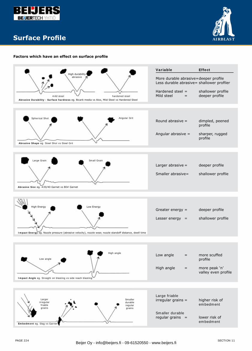
AIRBLAST
PAGE 224
Surface Profile
Factors which have an effect on surface profile
Abrasive Durability - Surface hardness eg. Bicarb media vs Alox, Mild Steel vs Hardened Steel
High durability abrasive
mild steel hardened steel
Abrasive Shape eg. Steel Shot vs Steel Grit
Spherical Shot Angular Grit
Abrasive Size eg. #20/40 Garnet vs 80# Garnet
Large Grain Small Grain
Impact Energy eg. Nozzle pressure (abrasive velocity), nozzle wear, nozzle standoff distance, dwell time
High Energy Low Energy
Impact Angle eg. Straight on blasting vs side reach blasting
Low angle
High angle
Embedment eg. Slag vs Garnet
Largerirregularfriablegrains
Smallerdurableregulargrains
Variable Effect
More durable abrasive= deeper profileLess durable abrasive= shallower profiler
Hardened steel = shallower profileMild steel = deeper profile
Round abrasive = dimpled, peened profile
Angular abrasive = sharper, rugged profile
Greater energy = deeper profile
Lesser energy = shallower profile
Larger abrasive = deeper profile
Smaller abrasive= shallower profile
Low angle = more scuffed profile
High angle = more peak ‘n’ valley even profile
Large friableirregular grains = higher risk of embedment
Smaller durableregular grains = lower risk of embedment
SECTION 11Beijer Oy - [email protected] - 09-61520550 - www.beijers.fi
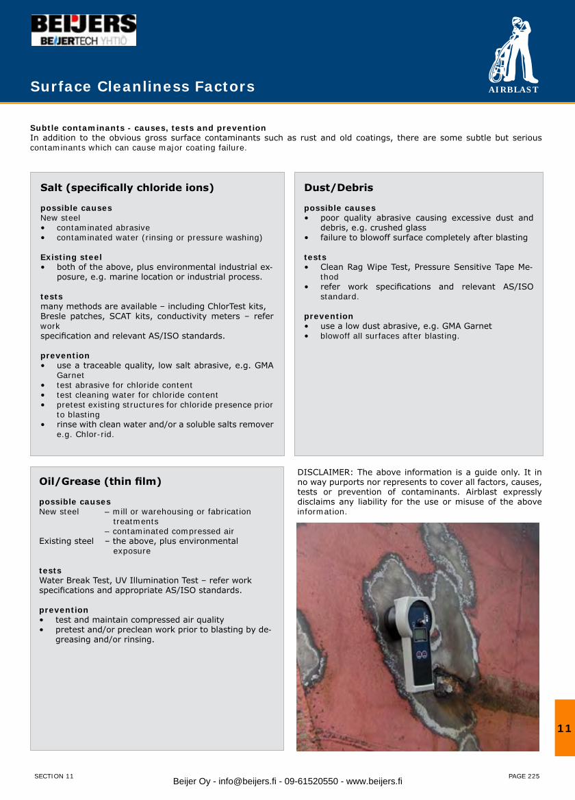
AIRBLAST
PAGE 225
Subtle contaminants - causes, tests and preventionIn addition to the obvious gross surface contaminants such as rust and old coatings, there are some subtle but serious contaminants which can cause major coating failure.
Salt (specifically chloride ions)
possible causesNew steel
contaminated abrasive• contaminated water (rinsing or pressure washing)•
Existing steelboth of the above, plus environmental industrial ex-• posure, e.g. marine location or industrial process.
testsmany methods are available – including ChlorTest kits,Bresle patches, SCAT kits, conductivity meters – refer workspecification and relevant AS/ISO standards.
preventionuse a traceable quality, low salt abrasive, e.g. GMA • Garnettest abrasive for chloride content• test cleaning water for chloride content• pretest existing structures for chloride presence prior • to blastingrinse with clean water and/or a soluble salts remover • e.g. Chlor-rid.
Oil/Grease (thin film)
possible causesNew steel – mill or warehousing or fabrication treatments – contaminated compressed airExisting steel – the above, plus environmental exposure
testsWater Break Test, UV Illumination Test – refer workspecifications and appropriate AS/ISO standards.
preventiontest and maintain compressed air quality• pretest and/or preclean work prior to blasting by de-• greasing and/or rinsing.
Dust/Debris
possible causespoor quality abrasive causing excessive dust and • debris, e.g. crushed glassfailure to blowoff surface completely after blasting•
testsClean Rag Wipe Test, Pressure Sensitive Tape Me-• thodrefer work specifications and relevant AS/ISO • standard.
preventionuse a low dust abrasive, e.g. GMA Garnet• blowoff all surfaces after blasting.•
DISCLAIMER: The above information is a guide only. It in no way purports nor represents to cover all factors, causes, tests or prevention of contaminants. Airblast expressly disclaims any liability for the use or misuse of the above information.
Surface Cleanliness Factors
11
SECTION 11 Beijer Oy - [email protected] - 09-61520550 - www.beijers.fi
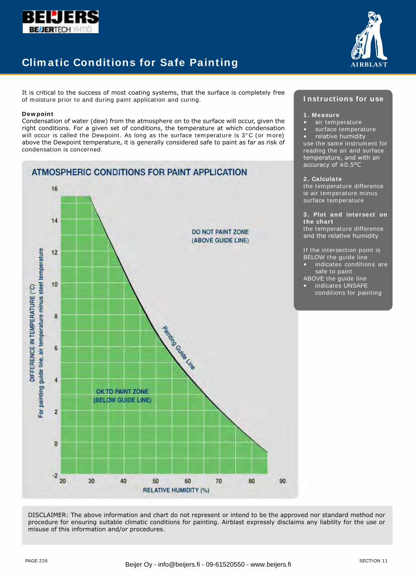
AIRBLAST
PAGE 226
Climatic Conditions for Safe Painting
It is critical to the success of most coating systems, that the surface is completely free of moisture prior to and during paint application and curing.
DewpointCondensation of water (dew) from the atmosphere on to the surface will occur, given the right conditions. For a given set of conditions, the temperature at which condensation will occur is called the Dewpoint. As long as the surface temperature is 3°C (or more) above the Dewpoint temperature, it is generally considered safe to paint as far as risk of condensation is concerned.
DISCLAIMER: The above information and chart do not represent or intend to be the approved nor standard method nor procedure for ensuring suitable climatic conditions for painting. Airblast expressly disclaims any liability for the use or misuse of this information and/or procedures.
Instructions for use
1. Measureair temperature• surface temperature• relative humidity•
use the same instrument for reading the air and surfacetemperature, and with anaccuracy of ±0.5°C
2. Calculatethe temperature differenceie air temperature minussurface temperature
3. Plot and intersect on the chartthe temperature differenceand the relative humidity
If the intersection point isBELOW the guide line
indicates conditions are • safe to paint
ABOVE the guide lineindicates UNSAFE • conditions for painting
SECTION 11Beijer Oy - [email protected] - 09-61520550 - www.beijers.fi