Embed Size (px)
Citation preview
SAE Technical Standards Board Rules provide that: “This report is published by SAE to advance the state of technical and engineering sciences. The use of this report is entirelyvoluntary, and its applicability and suitability for any particular use, including any patent infringement arising therefrom, is the sole responsibility of the user.”
SAE reviews each technical report at least every five years at which time it may be reaffirmed, revised, or cancelled. SAE invites your written comments and suggestions.
QUESTIONS REGARDING THIS DOCUMENT: (724) 772-8512 FAX: (724) 776-0243TO PLACE A DOCUMENT ORDER; (724) 776-4970 FAX: (724) 776-0790
SAE WEB ADDRESS http://www.sae.org
Copyright 1999 Society of Automotive Engineers, Inc.All rights reserved. Printed in U.S.A.
SURFACEVEHICLE
400 Commonwealth Drive, Warrendale, PA 15096-0001RECOMMENDEDPRACTICE
J2178-2REV.
MAR1999
Issued 1993-06Revised 1999-03
Superseding J2178-2 MAY1997
Class B Data Communication Network Messages—Part 2: Data Parameter Definitions
TABLE OF CONTENTS
1. Scope ....................................................................................................................................................... 21.1 Standardized Parameter Definitions......................................................................................................... 3
2. References ............................................................................................................................................... 42.1 Applicable Publications ............................................................................................................................ 42.1.1 SAE Publications ...................................................................................................................................... 42.1.2 Other Publications .................................................................................................................................... 4
3. Definitions................................................................................................................................................. 4
4. Abbreviations and Acronyms.................................................................................................................... 5
5. General Information.................................................................................................................................. 65.1 Part 2 Overview........................................................................................................................................ 65.2 How to Use This Document...................................................................................................................... 6
6. Parameter Reference Number (PRN) Structure....................................................................................... 7
7. Parameter Formats................................................................................................................................... 97.1 Bit Mapped Parameters............................................................................................................................ 97.1.1 Bit Mapped Data Without Mask Byte(s).................................................................................................... 97.1.2 Bit Mapped Data With Mask Byte(s)....................................................................................................... 107.1.3 Bit Values ............................................................................................................................................... 117.2 Byte (8 Bit) Parameters .......................................................................................................................... 117.3 Word (16 Bit) Parameters....................................................................................................................... 117.4 Multi-Byte (16 Bit) Parameters ............................................................................................................... 127.5 Multiple Parameter Packets.................................................................................................................... 12
8. Specific Parameter (PRN) Assignments................................................................................................. 128.1 Specific Parameters ............................................................................................................................... 12

SAE J2178-2 Revised MAR1999
-2-
9. Scaling, Limit, Offset, and Transfer Function (SLOT) Definitions ........................................................... 249.1 Multiple Parameter Packeted (PKT) SLOTs ........................................................................................... 249.1.1 Multiple Parameter Packeted Assignments ............................................................................................ 249.2 Bit Mapped Without Mask (BMP) SLOTs................................................................................................ 269.2.1 Bit Mapped Without Mask Parameter Assignments................................................................................ 309.3 Bit Mapped With Mask Bytes (BMM) SLOTs .......................................................................................... 309.3.1 Bit Mapped With Mask Parameter Assignments..................................................................................... 309.4 Unsigned Numeric (UNM) SLOTs........................................................................................................... 309.4.1 Unsigned Numeric Variable Assignments............................................................................................... 319.5 2’ Complement Signed Numeric (SNM) SLOT’s..................................................................................... 339.5.1 2’s Complement Signed Numeric Variable Assignments........................................................................ 349.6 State Encoded (SED) SLOT’s ................................................................................................................ 349.6.1 State Encoded Variable Assignments .................................................................................................... 349.7 ASCII Encoded (ASC) SLOT’s ............................................................................................................... 409.7.1 ASCII Encoded Variable Assignments ................................................................................................... 409.7.2 ASCII Character Set ............................................................................................................................... 429.8 Binary Coded Decimal (BCD) SLOT’s .................................................................................................... 429.8.1 Binary Coded Decimal (BCD) Variable Assignments ............................................................................. 429.9 Signed Floating Point (Scientific Notation) (SFP) SLOT......................................................................... 449.9.1 Signed Floating Point Variable Assignment............................................................................................ 45
10. Multiple Frame, Single Parameter Format .............................................................................................. 45
11. Manufacturer PRN Usage by SAE J2178 Part ....................................................................................... 46
12. Notes ...................................................................................................................................................... 5212.1 Marginal Indicia....................................................................................................................................... 52
Appendix A Parameter Name Cross Reference ........................................................................................................ 53
1. Scope— This SAE Recommended Practice defines the information contained in the header and data fields ofnon-diagnostic messages for automotive serial communications based on SAE J1850 Class B networks. Thisdocument describes and specifies the header fields, data fields, field sizes, scaling, representations, and datapositions used within messages.
The general structure of a SAE J1850 message frame without in-frame response is shown in Figure 1. Thestructure of a SAE J1850 message with in-frame response is shown in Figure 2. Figures 1 and 2 also show thescope of frame fields defined by this document for non-diagnostic messages. Refer to SAE J1979 forspecifications of emissions related diagnostic message header and data fields. Refer to SAE J2190 for thedefinition of other diagnostic data fields. The description of the network interface hardware, basic protocoldefinition, electrical specifications, and the CRC byte are given in SAE J1850.
FIGURE 1— SCOPE OF SAE J2178 FOR A SAE J1850 FRAME WITHOUT IN-FRAME RESPONSE (IFR)

SAE J2178-2 Revised MAR1999
-3-
FIGURE 2— SCOPE OF SAE J2178 FOR A SAE J1850 FRAME WITH IN-FRAME RESPONSE (IFR)
SAE J1850 defines two and only two formats of message headers. They are the Single Byte header formatand the Consolidated header format. The Consolidated header format has two forms, a single byte form and athree byte form. This document covers all of these formats and forms to identify the contents of messageswhich could be sent on a SAE J1850 network.
This document consists of four parts, each published separately.
SAE J2178-1, Part 1 of SAE J2178 (Titled: Detailed Header Formats and Physical Address Assignments)describes the two allowed forms of message header formats, Single Byte and Consolidated. It also containsthe physical node address range assignments for the typical sub-systems of an automobile.
SAE J2178-2, Part 2 of SAE J2178 (this part, Titled: Data Parameter Definitions) defines the standardparametric data which may be exchanged on SAE J1850 (Class B) networks. The parameter scaling, ranges,and transfer functions are specified. Messages which refer to these parametric definitions shall always adhereto these parametric definitions. It is intended that at least one of the definitions for each parameter in this partmatch the SAE J1979 definition.
SAE J2178-3, Part 3 of SAE J2178 (Titled: Frame IDs for Single Byte Forms of Headers) defines the messageassignments for the Single Byte header format and the one byte form of the Consolidated header format.
SAE J2178-4, Part 4 of SAE J2178 (Titled: Message Definition for Three Byte Headers) defines the messageassignments for the three byte form of the Consolidated header format.
1.1 Standardized Parameter Definitions— The parameters used to describe data variables are one of the mostimportant functions of this document. To achieve commonality of messages in Class B networks, the dataparameters must become standardized. This applies to data parameter definitions for use during normalvehicle operations as well as during diagnostic operations. By using common parameter definitions for non-diagnostic and diagnostic functions on the network, the modules which form the network can maintain oneimage or description of a data parameter.
At this time however, it is felt that there is not enough experience and commonality of philosophy within theindustry to define standard parameters. The purpose of this document is therefore to provide standardmethods of defining parameters and examples of defined parameters for many potential applications within avehicle. With this basis, it should be possible to avoid the definition of arbitrarily different parameters andmove toward standard parameters in the future.
Where parameters have been defined in the Diagnostic Test Modes, documents (SAE J1979 and J2190), suchas Parameter Identifies for diagnostic purposes, the definitions in Part 2 of this document match the diagnosticdefinition.

SAE J2178-2 Revised MAR1999
-4-
SAE J2178-2 defines the parameters to be used for non-diagnostic and diagnostic data format definitions. Fornew parameter definitions which are needed in the future, the new definitions, if they are expected to becomewidely used, must be integrated into this document for commonality across these types of applications. Ofcourse, manufacturers are free to assign their own definitions to data parameters which are unique orproprietary to their products. They are, however, restricted to using the “Manufacturer Reserved” messageheader assignments in Parts 3 and 4 of this document when using these unique or proprietary data parameterdefinitions.
2. References
2.1 Applicable Publications— The following publications form a part of this specification to the extent specifiedherein. Unless otherwise indicated, the latest issue of SAE publications shall apply.
2.1.1 SAE PUBLICATIONS— Available from SAE, 400 Commonwealth Drive, Warrendale, PA 15096-0001.
SAE J1213-1— Glossary of Vehicle Networks for Multiplex and Data CommunicationSAE J1850— Class B Data Communication Network InterfaceSAE J1930— Electrical/Electronic Systems Diagnostic Terms, Definitions, Abbreviations, and AcronymsSAE J1979— E/E Diagnostic Test ModesSAE J2190— Enhanced E/E Diagnostic Test Modes
2.1.2 OTHER PUBLICATIONS
ANSI/IEEE Std 754-1985 August 12, 1985— IEEE Standard for Binary Floating-Point Arithmetic
3. Definitions
3.1 Data [Data Field]— Data and data field are used interchangeably in this document and they both refer to afield within a frame that may include bytes with parameters pertaining to the message and/or secondary IDand/or extended addresses and/or test modes which further defines a particular message content beingexchanged over the network.
3.2 Extended Address— The extended address is a means to allow a message to be addressed to a specificgeographical location or zone of the vehicle, independent of any node’s physical address.
3.3 Frame— A frame is one complete transmission of information which may or may not include an In-FrameResponse. The frame is enclosed by the start of frame and end of frame symbols. For Class B networks, eachframe contains one and only one message (see “message” definition).
3.4 Frame ID— The Frame ID is the header byte for the Single Byte Header format and the one byte form of theconsolidated header format. The definition of the Frame ID is found in SAE J2178-3. This header byte definesthe target and source and content of the frame.
3.5 Functional Addressing— Functional addressing allows a message to be addressed or sent to one or morenodes on the network interested in that function. Functional addressing is intended for messages that may beof interest to more than a single node. For example, an exterior lamp “off” message could be sent to all nodescontrolling the vehicle exterior lamps by using a functional address. The functional address consists of aprimary ID and may include a secondary ID and may also include an extended address.
3.6 Header [Header Field]— The header (or header field, used interchangeably) is a one or three byte field withina frame which contains information about the message priority, message source and target addressing,message type, and in-frame response type.

SAE J2178-2 Revised MAR1999
-5-
3.7 In-Frame Response (IFR) Type— The IFR type identifies the form of the in-frame response which is expectedwithin that message.
3.8 Load— The load command indicates the operation of directly replacing the current/existing value of aparameter with the parameter value(s) contained in the message.
3.9 Message— A message consists of all of the bytes of a frame excluding the delimiter symbols (SOF, EOD,EOF, NB).
3.10 Modify— The modify command indicates the operation of using the message data parameter value to change(e.g., increment, decrement, or toggle) the current/existing value.
3.11 Parameter— A parameter is the variable quantity included in some messages. The parameter value, scaling,offset, units, transfer function, etc., are unique to each particular message. (The assigned parameters arecontained herein.)
3.12 Physical Addressing— Physical addressing allows a message to be addressed to a specific node or to allnodes or to a non-existent, null node. The information in this message is only of relevance to a particular node,so the other nodes on the bus should ignore the message, except for the case of the “all nodes” address.
3.13 Primary ID— The primary ID identifies the target for this functional message. This is the primary discriminatorused to group functions into main categories.
3.14 Priority— The priority describes the rank order and precedence of a message. Based upon the SAE J1850,Class B arbitration process, the message with the highest priority will win arbitration.
3.15 Report— A report indicates the transmission of parametric data values, based on: a change of state; a changeof value; on a periodic rate basis; or as a response to a specific request.
3.16 Request— A request is a command to, or a query for data, or action from another node on the network.
3.17 Response Data— The response data is the information from a node on the network in response to a requestfrom another node on the network. This may be an in-frame response or a report type of message.
3.18 Secondary ID— The secondary ID (along with the primary ID or Frame ID) identifies the functional target nodefor a message. The purpose of the secondary ID field within the frame is to further define the function or actionbeing identified by the primary ID.
4. Abbreviations and Acronyms
4WD Four (4) Wheel DriveA/C Air ConditioningASC ASCII Encoded SLOTBCD Binary Coded Decimal (BCD) SLOTBMM Bit Mapped with Mask SLOTBMP Bit Mapped without Mask SLOTCRC Cyclic Redundancy CheckCS ChecksumDTC Diagnostic Trouble CodeEOD End of DataEOF End of FrameERR Error DetectionEV-ETS Electric Vehicle Energy Transfer SystemEVSE Electric Vehicle Supply Equipment
SAE J2178-2 Revised MAR1999
-6-
HVAC Heating, Ventilation, Air ConditioningID IdentifierIFR In-Frame ResponseLSB Least Significant Bit/ByteMAF Mass Air FlowMIL Malfunction Indicator LampMSB Most Significant Bit/ByteNB Normalization BitPID Parameter Identification (number, NOT the primary ID, see Section 8)PKT Multiple Parameter Packet SLOTPRN Parameter Reference NumberPRNDL Park, Reverse, Neutral, Drive, and Low - IndicatorRPM Revolutions Per MinuteSED State Encoded SLOTSFP Signed Floating Point (Scientific Notation) SLOTSLOT Scaling, Limit, Offset, and Transfer Function (see Section 9)SNM 2’s Complement Signed Numeric SLOTSOF Start of FrameUNM Unsigned Numeric SLOTVIN Vehicle Identification Number
5. General Information
5.1 Part 2 Overview— Section 6 provides a description of the parameter reference number (PRN) numbergroupings used for assigning PRN numbers to individual parameters. Section 7 defines the formats used todefine all standard parameters to be used in SAE J2178 messages. Section 8 defines the specific parameterassignments in terms of names, units, and scale factor reference. Section 9 defines the actual parameterspecifications (SLOT), in terms of the length, bit resolution, range, scale factor details, etc. Section 10describes the case of very long parameters which cannot be transmitted in a single message. Table 30provides a numerical cross reference to assist in finding the correct name of a parameter if the parameteridentification number is known. Appendix A is an alphabetical cross reference to assist in finding the correctparameter identification number if the parameter name is known.
The messages contain header fields and data fields, described in SAE J2178-1. The header field containstarget, source, priority, and message type information, while the data field contains optional additionaladdressing and parametric information. This document defines the parametric information.
For some applications, it is desirable to include multiple parameters in a single message. The multipleparameter format is called a packet in this document. For example, some diagnostic messages consist ofcombinations of these parameters to improve information density or to insure simultaneous readings ofdifferent variables. A very limited set of these combinations is defined here as industry standards but individualmanufacturers are free to use this form in manufacturer specific messages, as needed.
5.2 How to Use This Document— This document (SAE J2178-2) provides the definition of parameters which arecommonly found, or could be expected in vehicle Electrical/Electronic Systems today. These parameters havebeen defined to allow messages on a Class B communication system to have consistent meaning betweenmanufacturers and over time. The parameter definition consists of two parts, the “PRN” and the “SLOT.” The“PRN” (Parameter Reference Number) is a number used to identify a specific parameter by name, unit ofmeasure, and its associated “SLOT.” The “SLOT” defines the mathematical characteristics of parameters interms of its representation (Binary, Unsigned Numeric, ASCII, BCD, etc.), its scaling (1 Bit = ), its limits andoffsets, and its transfer function.

SAE J2178-2 Revised MAR1999
-7-
To find a parameter by name or PRN number, Appendices A and B provide cross references to the page of thisdocument where the PRN can be found. The PRN numbers have also been grouped by subsystem to enablethe reader to look for parameters if the name is not know.
If the parameter has not as yet been included in the list of PRNs, users can define new parameters in terms ofthe SLOTs which have been defined.
6. Parameter Reference Number (PRN) Structure— Parameter Reference Numbers (PRNs) are used tosimplify documentation. They do not, in themselves, have particular significance. PRNs do allow simplificationof reference, particularly for diagnostic purposes. To this end, a structure for PRN number assignments hasbeen developed. The structure is described in the following paragraphs.
All PRN addresses are two bytes long, with the first byte identifying a grouping or classification reference (referto Tables 1 and 2). The second byte is then a sequence number pointing to the specific parameter used (referto Tables 4 through 19). There has not been any attempt made to group or commonize the meaning in thesecond byte. The specific assignments are found in Section 8. Note that all PRN addresses are listed ashexadecimal numbers throughout this document.
SAE J1979 refers to PID numbers which are a single byte reference number. The first 256 PRNs defined here(first byte = 00), are identical with the SAE J1979 definitions.
Figure 3 shows the basic structure of PRNs and Tables 1 and 2 show bit assignments and address rangesbased on these assignments.
FIGURE 3— PRN STRUCTURE

SAE J2178-2 Revised MAR1999
-8-
TABLE 1— PRN GROUPINGS
7 6 5 System 4 3 Subgroup Address (Hex)
0 0 0 Powertrain 0 0 SAE J1979 Compatible 0000 - 00FF
0 0 Reserved 0100 - 07FF
0 1 Reserved 0800 - 0FFF
1 0 Engine 1000 - 17FF
1 1 Transmission 1800 - 1FFF
0 0 1 Chassis 0 0 Reserved 2000 - 27FF
0 1 Brakes/Tires/Wheels 2800 - 2FFF
1 0 Steering 3000 - 37FF
1 1 Suspension 3800 - 3FFF
0 1 0 Body 1 0 0 Reserved 4000 - 47FF
0 1 Reserved 4800 - 4FFF
1 0 Reserved 5000 - 57FF
1 1 Restraints 5800 - 5FFF
0 1 1 Body 2 0 0 Driver Info. 6000 - 67FF
0 1 Reserved 6800 - 6FFF
1 0 Lighting 7000 - 77FF
1 1 Reserved 7800 - 7FFF
1 0 0 Body 3 0 0 Audio 8000 - 87FF
0 1 Reserved 8800 - 8FFF
1 0 Pers. Comm. 9000 - 97FF
1 1 HVAC 9800 - 9FFF
101 Boyd 4 0 0 Convenience A000 - A7FF
0 1 Reserved A800 - AFFF
1 0 Reserved B000 - B7FF
1 1 Reserved B800 - BFFF
1 1 0 Other 1 0 0 Security C000 - C7FF
0 1 EV-ETS C800 - CFFF
1 0 Reserved D000 - D7FF
1 1 Reserved D800 - DFFF
1 1 1 Other 2 0 0 Config. Codes E000 - E7FF
0 1 Reserved E800 - EFFF
1 0 Tester/Diag. F000 - F7FF
1 1 Miscellaneous F800 - FFFF

SAE J2178-2 Revised MAR1999
-9-
7. Parameter Formats— Parameter values are represented in bit, byte, word, and multi-byte forms. The lengthof the parameter is uniquely associated with the message header and any included secondary ID field. Theseparameter definitions are referenced by one or more messages. The parameters allow a wide variety ofvariables, data definitions, and representations to provide the ability to use this definition for all messages,even when the industry standard messages are not useful for particular applications.
7.1 Bit Mapped Parameters— The bit mapped parameters, that is, those which have only two logical values (forexample: True/False), are handled in one of two ways. The “Q” bit described in Section 8 of SAE J2178-1 isused if there is only one bit of information. In many cases, however, the bit values are associated together andform byte groupings, generally around common functional characteristics. Bit mapped data are transmittedeither with or without corresponding mask bytes as described as follows:
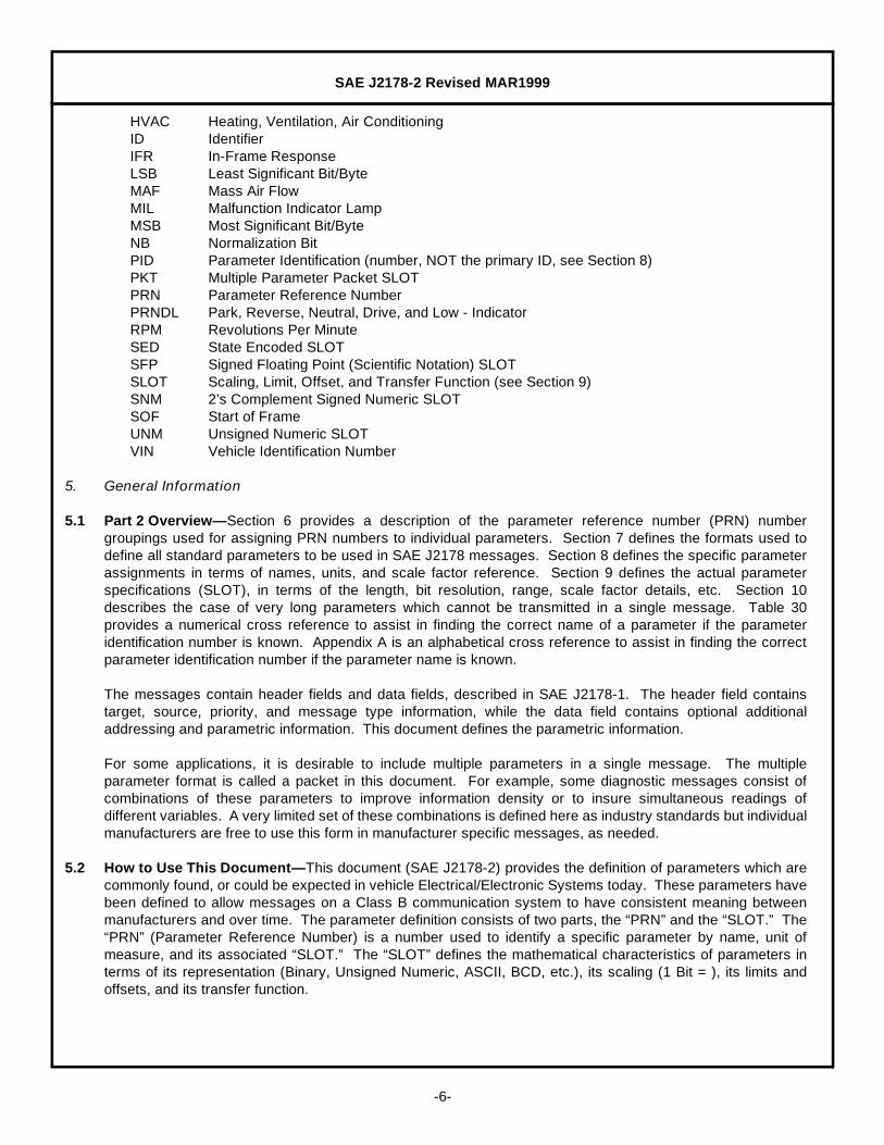
7.1.1 BIT MAPPED DATA WITHOUT MASK BYTE(S)— In some cases, such as configuration identification, there isinformation which can be grouped as binary bits which represent whether, for example, a function or test issupported in a system. This form does not allow the bits to be supplied from different nodes in the network.If the bits potentially come from more than one node, the form with mask bytes described in 7.1.2, is used.The general form of the bit data bytes without mask is shown in Figure 4.
TABLE 2— PRN RANGES
System Subgroup Address Map Size
Powertrain SAE J1979 Compatible 0000 - 00FF 0.25 K
Reserved 0100 - 0FFF 3.75 K
Engine 1000 - 17FF 2.00 K
Transmission 1800 - 1FFF 2.00 K
Chassis Reserved 2000 - 27FF 2.00 K
Brakes/Tires/Wheels 2800 - 2FFF 2.00 K
Steering 3000 - 37FF 2.00 K
Suspension 3800 - 3FFF 2.00 K
Body 1 Reserved 4000 - 57FF 6.00 K
Restraints 5800 - 5FFF 2.00 K
Body 2 Driver Information 6000 - 67FF 2.00 K
Reserved 6800 - 6FFF 2.00 K
Lighting 7000 - 77FF 2.00 K
Reserved 7800 - 7FFF 2.00 K
Body 3 Audio 8000 - 87FF 2.00 K
Reserved 8800 - 8FFF 2.00 K
Personal Communications 9000 - 97FF 2.00 K
HVAC 9800 - 9FFF 2.00 K
Body 4 Convenience A000 - A7FF 2.00 K
Reserved A800 - BFFF 6.00 K
Other 1 Security C000 - C7FF 2.00 K
EV-ETS C800 - CFFF 2.00 K
Reserved D000 - DFFF 4.00 K
Other 2 Configuration Codes E000 - E7FF 2.00 K
Reserved E800 - EFFF 2.00 K
Tester/Diagnostics F000 - F7FF 2.00 K
Miscellaneous F800 - FFFF 2.00 K
SAE J2178-2 Revised MAR1999
-10-
FIGURE 4— FORMAT FOR BIT DATA WITHOUT MASK
For these bit data cases, the bit names (that is: items) are somewhat different to emphasize the difference informat. These numbers are shown in Figure 5. If there is more than one byte of this form, the item numbersare incremented by one, sequentially, beginning at one from the MSB of the first byte.
FIGURE 5— BITS WITHOUT MASK BYTE
For definition purposes, it is also possible to describe a single or multiple bit group which is smaller than abyte but which is combined into a byte or multiple bytes when the complete message is defined. This is aconvenience used in this document to define some parameters. This definition notation applies equally tobyte(s) with or without masks.
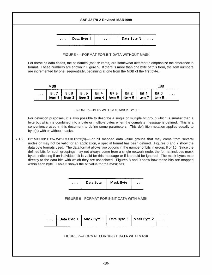
7.1.2 BIT MAPPED DATA WITH MASK BYTE(S)— For bit mapped data value groups that may come from severalnodes or may not be valid for an application, a special format has been defined. Figures 6 and 7 show thedata byte formats used. The data format allows two options in the number of bits in group; 8 or 16. Since thedefined bits for such groupings may not always come from a single network node, the format includes maskbytes indicating if an individual bit is valid for this message or if it should be ignored. The mask bytes mapdirectly to the data bits with which they are associated. Figures 8 and 9 show how these bits are mappedwithin each byte. Table 3 shows the bit value for the mask bits.
FIGURE 6— FORMAT FOR 8-BIT DATA WITH MASK
FIGURE 7— FORMAT FOR 16-BIT DATA WITH MASK

SAE J2178-2 Revised MAR1999
-11-
FIGURE 8— BIT MAPPED DATA BYTE
FIGURE 9— BIT MAPPED MASK BYTE
7.1.3 BIT VALUES— The general form of binary data is that 1 = true and 0 = false. One bit can carry a wide varietyof interpretations, depending on the subject that it describes.
7.2 Byte (8 Bit) Parameters— Data parameters which can be expressed in 8 bits or less are expressed in a byteformat. Byte parameters are the most common format. Figure 10 shows this format.
FIGURE 10— BYTE PARAMETERS
7.3 Word (16 Bit) Parameters— Data parameters which can be expressed in 9 to 16 bits are expressed in wordformat with the most significant byte transmitted first (high byte/low byte). Figure 11 shows this format.
FIGURE 11— WORD PARAMETERS
TABLE 3— MASK BIT ASSIGNMENT
Mask Bit Bit Mapped Masking
0 Not a Valid Bit
1 Valid Bit
SAE J2178-2 Revised MAR1999
-12-
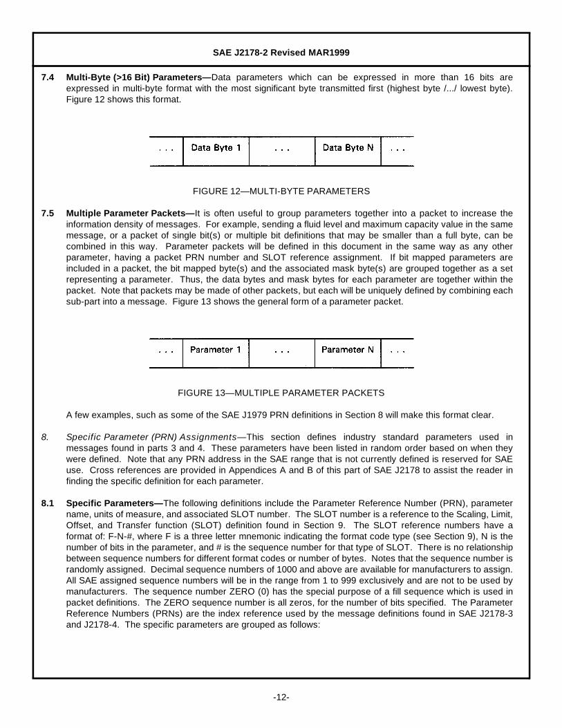
7.4 Multi-Byte (>16 Bit) Parameters— Data parameters which can be expressed in more than 16 bits areexpressed in multi-byte format with the most significant byte transmitted first (highest byte /.../ lowest byte).Figure 12 shows this format.
FIGURE 12— MULTI-BYTE PARAMETERS
7.5 Multiple Parameter Packets— It is often useful to group parameters together into a packet to increase theinformation density of messages. For example, sending a fluid level and maximum capacity value in the samemessage, or a packet of single bit(s) or multiple bit definitions that may be smaller than a full byte, can becombined in this way. Parameter packets will be defined in this document in the same way as any otherparameter, having a packet PRN number and SLOT reference assignment. If bit mapped parameters areincluded in a packet, the bit mapped byte(s) and the associated mask byte(s) are grouped together as a setrepresenting a parameter. Thus, the data bytes and mask bytes for each parameter are together within thepacket. Note that packets may be made of other packets, but each will be uniquely defined by combining eachsub-part into a message. Figure 13 shows the general form of a parameter packet.
FIGURE 13— MULTIPLE PARAMETER PACKETS
A few examples, such as some of the SAE J1979 PRN definitions in Section 8 will make this format clear.
8. Specific Parameter (PRN) Assignments— This section defines industry standard parameters used inmessages found in parts 3 and 4. These parameters have been listed in random order based on when theywere defined. Note that any PRN address in the SAE range that is not currently defined is reserved for SAEuse. Cross references are provided in Appendices A and B of this part of SAE J2178 to assist the reader infinding the specific definition for each parameter.
8.1 Specific Parameters— The following definitions include the Parameter Reference Number (PRN), parametername, units of measure, and associated SLOT number. The SLOT number is a reference to the Scaling, Limit,Offset, and Transfer function (SLOT) definition found in Section 9. The SLOT reference numbers have aformat of: F-N-#, where F is a three letter mnemonic indicating the format code type (see Section 9), N is thenumber of bits in the parameter, and # is the sequence number for that type of SLOT. There is no relationshipbetween sequence numbers for different format codes or number of bytes. Notes that the sequence number israndomly assigned. Decimal sequence numbers of 1000 and above are available for manufacturers to assign.All SAE assigned sequence numbers will be in the range from 1 to 999 exclusively and are not to be used bymanufacturers. The sequence number ZERO (0) has the special purpose of a fill sequence which is used inpacket definitions. The ZERO sequence number is all zeros, for the number of bits specified. The ParameterReference Numbers (PRNs) are the index reference used by the message definitions found in SAE J2178-3and J2178-4. The specific parameters are grouped as follows:

SAE J2178-2 Revised MAR1999
-13-
Table 4 SAE J1979 Compatible PRN/PID AssignmentsTable 5 Engine PRN AssignmentsTable 6 Transmission PRN AssignmentsTable 7 Brakes/Tires/Wheels PRN AssignmentsTable 8 Steering PRN AssignmentsTable 9 Suspension PRN AssignmentsTable 10 Restraints PRN AssignmentsTable 11 Driver Information PRN AssignmentsTable 12 Lighting PRN AssignmentsTable 13 Audio PRN AssignmentsTable 14 Personal Communication PRN AssignmentsTable 15 HVAC PRN AssignmentsTable 16 Convenience PRN AssignmentsTable 17 Security PRN AssignmentsTable 18 Electric Vehicle Energy Transfer SystemTable 19 Configuration Codes PRN AssignmentsTable 20 Tester/Diagnostics PRN AssignmentsTable 21 Miscellaneous PRN Assignments
TABLE 4— SAE J1979 COMPATIBLE PRN ASSIGNMENTS(PRNS 0000 - 00FF)
PRN Parameter NameResolution
(1 Bit =) Units of MeasureSLOT #(F-N-#)
0000 PIDs Supported (01h - 20h) — Bit Mapped BMP-32-1
0001 Number of Emission-Related Trouble Codes and MIL Status
— Packeted PKT-32-1
0002 Trouble Code that Caused Freeze Frame Storage
— Packeted PKT-16-1
0003 Fuel System Status — Packeted PKT-16-2
0004 Calculated Load Value 100/255 % Full Load UNM-08-61
0005 Engine Coolant Temperature 1 Degrees Centigrade UNM-08-102
0006 Short Term Fuel Trim - Bank 1 100/128 % Enrichment UNM-08-92
0007 Long Term Fuel Trim - Bank 1 100/128 % Enrichment UNM-08-92
0008 Short Term Fuel Trim - Bank 2 100/128 % Enrichment UNM-08-92
0009 Long Term Fuel Trim - Bank 2 100/128 % Enrichment UNM-08-92
000A Fuel Pressure (Gage) 3 kPaG UNM-08-131
000B Intake Manifold Absolute Pressure 1 kPaA UNM-08-101
000C Engine RPM - High Resolution 1/4 RPM UNM-16-31
000D Vehicle Speed - Low Resolution - Metric
1 KPH UNM-08-101
000E Ignition Timing Advance (#1) 1/2 Degrees before TDC UNM-08-72
000F Intake Air Temperature 1 Degrees Centrigrade UNM-08-102
0010 Air Flow Rate from MAF 1/100 gm/sec UNM-16-11
0011 Absolute Throttle #1 Position 100/255 % Full Throttle UNM-08-61
0012 Commanded Secondary Air — Bit Mapped BMP-08-5
0013 Oxygen Sensor Location — Bit Mapped BMP-08-6
0014 Oxygen Sensor - BANK 1 - Sensor 1 — Packeted PKT-16-3
0015 Oxygen Sensor - BANK 1 - Sensor 2 — Packeted PKT-16-3
0016 Oxygen Sensor - BANK 1 - Sensor 3 — Packeted PKT-16-3
0017 Oxygen Sensor - BANK 1 - Sensor 4 — Packeted PKT-16-3
0018 Oxygen Sensor - BANK 2 - Sensor 1 — Packeted PKT-16-3
0019 Oxygen Sensor - BANK 2 - Sensor 2 — Packeted PKT-16-3

SAE J2178-2 Revised MAR1999
-14-
001A Oxygen Sensor - BANK 2 - Sensor 3 — Packeted PKT-16-3
001B Oxygen Sensor - BANK 2 - Sensor 4 — Packeted PKT-16-3
001C Reserved SAE — — —
001D Reserved SAE — — —
001E Reserved SAE — — —
001F Reserved SAE — — —
0020 PIDs Supported (21h - 40h) — Bit Mapped BMP-32-2
0021-003F
Reserved SAE — — —
0040 PIDs Supported (41h - 60h) — Bit Mapped BMP-32-3
0041-00FF
Reserved SAE — — —
TABLE 5— ENGINE PRN ASSIGNMENTS(PRNS 1000 - 17FF)
PRN Parameter NameResolution
(1 Bit =) Units of MeasureSLOT #(F-N-#)
1000 MIL Status — Bit Mapped BMP-01-1
1001 Number of Emissions Related DTCs 1 Quantity UNM-07-1
1002 Continuous Evaluation Supported — Bit Mapped BMP-08-1
1003 Trip Evaluation Supported — Bit Mapped BMP-08-2
1004 Trip Evaluation Complete — Bit Mapped BMP-08-3
1005 Subsystem Category of DTC — State Encoded SED-02-1
1006 Most Significant Digit of DTC — State Encoded SED-02-2
1007 Lower 3 Digits of DTC — BCD BCD-12-1
1008 Fuel System Status - Bank 1 — Bit Mapped BMP-08-4
1009 Fuel System Status - Bank 2 — Bit Mapped BMP-08-4
100A Oxygen Sensor Voltage 1/200 volts UNM-08-11
100B Short Term Fuel Trim 100/128 % Enrichment UNM-08-92
100D Most Significant Digit of VIN Number — ASCII ASC-08-11
100E A/C Clutch Load 25 Watts UNM-08-165
1015 Injector On Time 2048 microseconds UNM-08-231
1016 Injector On Time - High Resolution 64 microseconds UNM-16-61
1017 MIL Status - Expanded — Bit Mapped BMP-08-8
1018 Fuel Consumed - Volume 1 µ liter UNM-16-41
1019 Crankshaft Torque - Absolute 4 NM Torque UNM-08-141
1020 Crankshaft Torque - Percent 100/255 % Maximum Torque UNM-08-61
1021 Engine Boost 100/255 % Full Boost UNM-08-61
1022 Engine RPM - Low Resolution 32 RPM UNM-08-171
1023 Engine Idle RPM 16 RPM UNM-08-161
1024 Engine Revolutions 2 Quantity UNM-08-121
1025 Barometric Pressure 1 kPaA UNM-08-101
1026 Engine Coolant Level - Percent 1/2 % Full UNM-08-71
1027 Engine Coolant Level - Volume 1/10 liters UNM-08-41
1028 Engine Coolant Capacity 1/10 liters UNM-08-41
1029 Engine Coolant Pressure 4 kPaG UNM-08-141
102A Engine Coolant Fan #1 Speed 100/255 % Full On UNM-08-61
TABLE 4— SAE J1979 COMPATIBLE PRN ASSIGNMENTS(PRNS 0000 - 00FF) (CONTINUED)
PRN Parameter NameResolution
(1 Bit =) Units of MeasureSLOT #(F-N-#)
SAE J2178-2 Revised MAR1999
-15-
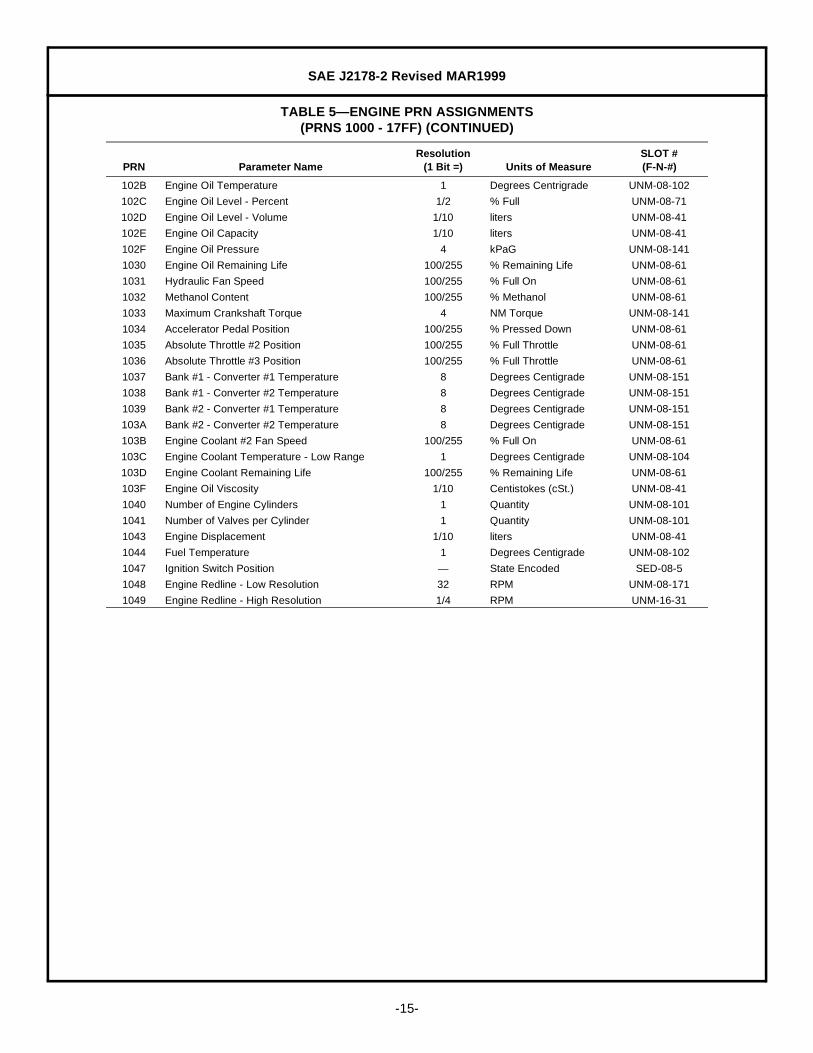
102B Engine Oil Temperature 1 Degrees Centrigrade UNM-08-102
102C Engine Oil Level - Percent 1/2 % Full UNM-08-71
102D Engine Oil Level - Volume 1/10 liters UNM-08-41
102E Engine Oil Capacity 1/10 liters UNM-08-41
102F Engine Oil Pressure 4 kPaG UNM-08-141
1030 Engine Oil Remaining Life 100/255 % Remaining Life UNM-08-61
1031 Hydraulic Fan Speed 100/255 % Full On UNM-08-61
1032 Methanol Content 100/255 % Methanol UNM-08-61
1033 Maximum Crankshaft Torque 4 NM Torque UNM-08-141
1034 Accelerator Pedal Position 100/255 % Pressed Down UNM-08-61
1035 Absolute Throttle #2 Position 100/255 % Full Throttle UNM-08-61
1036 Absolute Throttle #3 Position 100/255 % Full Throttle UNM-08-61
1037 Bank #1 - Converter #1 Temperature 8 Degrees Centigrade UNM-08-151
1038 Bank #1 - Converter #2 Temperature 8 Degrees Centigrade UNM-08-151
1039 Bank #2 - Converter #1 Temperature 8 Degrees Centigrade UNM-08-151
103A Bank #2 - Converter #2 Temperature 8 Degrees Centigrade UNM-08-151
103B Engine Coolant #2 Fan Speed 100/255 % Full On UNM-08-61
103C Engine Coolant Temperature - Low Range 1 Degrees Centigrade UNM-08-104
103D Engine Coolant Remaining Life 100/255 % Remaining Life UNM-08-61
103F Engine Oil Viscosity 1/10 Centistokes (cSt.) UNM-08-41
1040 Number of Engine Cylinders 1 Quantity UNM-08-101
1041 Number of Valves per Cylinder 1 Quantity UNM-08-101
1043 Engine Displacement 1/10 liters UNM-08-41
1044 Fuel Temperature 1 Degrees Centigrade UNM-08-102
1047 Ignition Switch Position — State Encoded SED-08-5
1048 Engine Redline - Low Resolution 32 RPM UNM-08-171
1049 Engine Redline - High Resolution 1/4 RPM UNM-16-31
TABLE 5— ENGINE PRN ASSIGNMENTS(PRNS 1000 - 17FF) (CONTINUED)
PRN Parameter NameResolution
(1 Bit =) Units of MeasureSLOT #(F-N-#)
SAE J2178-2 Revised MAR1999
-16-
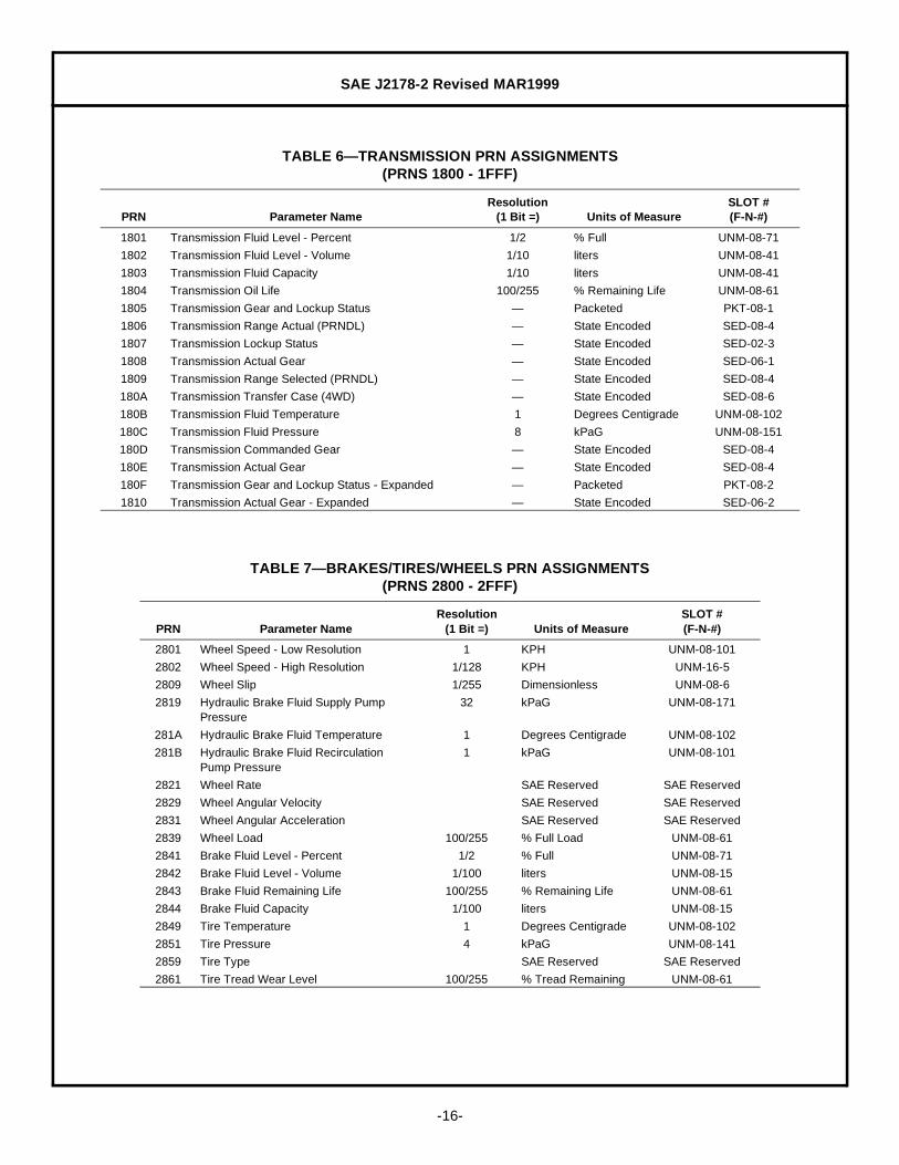
TABLE 6— TRANSMISSION PRN ASSIGNMENTS(PRNS 1800 - 1FFF)
PRN Parameter NameResolution
(1 Bit =) Units of MeasureSLOT #(F-N-#)
1801 Transmission Fluid Level - Percent 1/2 % Full UNM-08-71
1802 Transmission Fluid Level - Volume 1/10 liters UNM-08-41
1803 Transmission Fluid Capacity 1/10 liters UNM-08-41
1804 Transmission Oil Life 100/255 % Remaining Life UNM-08-61
1805 Transmission Gear and Lockup Status — Packeted PKT-08-1
1806 Transmission Range Actual (PRNDL) — State Encoded SED-08-4
1807 Transmission Lockup Status — State Encoded SED-02-3
1808 Transmission Actual Gear — State Encoded SED-06-1
1809 Transmission Range Selected (PRNDL) — State Encoded SED-08-4
180A Transmission Transfer Case (4WD) — State Encoded SED-08-6
180B Transmission Fluid Temperature 1 Degrees Centigrade UNM-08-102
180C Transmission Fluid Pressure 8 kPaG UNM-08-151
180D Transmission Commanded Gear — State Encoded SED-08-4
180E Transmission Actual Gear — State Encoded SED-08-4
180F Transmission Gear and Lockup Status - Expanded — Packeted PKT-08-2
1810 Transmission Actual Gear - Expanded — State Encoded SED-06-2
TABLE 7— BRAKES/TIRES/WHEELS PRN ASSIGNMENTS(PRNS 2800 - 2FFF)
PRN Parameter NameResolution
(1 Bit =) Units of MeasureSLOT #(F-N-#)
2801 Wheel Speed - Low Resolution 1 KPH UNM-08-101
2802 Wheel Speed - High Resolution 1/128 KPH UNM-16-5
2809 Wheel Slip 1/255 Dimensionless UNM-08-6
2819 Hydraulic Brake Fluid Supply Pump Pressure
32 kPaG UNM-08-171
281A Hydraulic Brake Fluid Temperature 1 Degrees Centigrade UNM-08-102
281B Hydraulic Brake Fluid Recirculation Pump Pressure
1 kPaG UNM-08-101
2821 Wheel Rate SAE Reserved SAE Reserved
2829 Wheel Angular Velocity SAE Reserved SAE Reserved
2831 Wheel Angular Acceleration SAE Reserved SAE Reserved
2839 Wheel Load 100/255 % Full Load UNM-08-61
2841 Brake Fluid Level - Percent 1/2 % Full UNM-08-71
2842 Brake Fluid Level - Volume 1/100 liters UNM-08-15
2843 Brake Fluid Remaining Life 100/255 % Remaining Life UNM-08-61
2844 Brake Fluid Capacity 1/100 liters UNM-08-15
2849 Tire Temperature 1 Degrees Centigrade UNM-08-102
2851 Tire Pressure 4 kPaG UNM-08-141
2859 Tire Type SAE Reserved SAE Reserved
2861 Tire Tread Wear Level 100/255 % Tread Remaining UNM-08-61

SAE J2178-2 Revised MAR1999
-17-
TABLE 8— STEERING PRN ASSIGNMENTS(PRNS 3000 - 37FF)
PRN Parameter NameResolution
(1 Bit =) Units of MeasureSLOT #(F-N-#)
3001 Steering Wheel Angle 6 Degrees CW from Center SNM-08-61
3005 Power Steering Fluid Temperature 1 Degrees Centigrade UNM-08-102
3006 Power Steering Fluid Pressure 100 kPaG UNM-08-185
3007 Power Steering Fluid Level - Percent 1/2 % Full UNM-08-71
3008 Power Steering Fluid Level - Volume 1/100 liters UNM-08-15
3009 Power Steering Fluid Remaining Life 100/255 % Remaining Life UNM-08-61
300B Power Steering Fluid Capacity 1/100 liters UNM-08-15
300C Steering Wheel Rate 1 RPM UNM-08-101
300D Steering Wheel Torque 1 NM Torque UNM-08-101
300E Wheel Steer Angle 1/2 Degrees CW from Center SNM-08-11
TABLE 9— SUSPENSION PRN ASSIGNMENTS(PRNS 3800 - 3FFF)
PRN Parameter NameResolution
(1 Bit =) Units of MeasureSLOT #(F-N-#)
3801 Lateral Acceleration SAE Reserved SAE Reserved
3802 Longitudinal Acceleration SAE Reserved SAE Reserved
3803 Yaw Acceleration SAE Reserved SAE Reserved
3804 Suspension Ride Setting 100/255 % Stiff Setting UNM-08-61
3805 Suspension Fluid Temperature 1 Degrees Centigrade UNM-08-102
3806 Suspension Fluid Pressure 100 kPaG UNM-08-185
3807 Suspension Fluid Level - Percent 1/2 % Full UNM-08-71
3808 Suspension Fluid Level - Volume 1/32 liters UNM-08-26
3809 Suspension Fluid Remaining Life 100/255 % Remaining Life UNM-08-61
380A Suspension Fluid Capacity 1/32 liters UNM-08-26
380B Vehicle Lateral Velocity SAE Reserved SAE Reserved
380C Vehicle Longitudinal Velocity SAE Reserved SAE Reserved
830D Vehicle Yaw Velocity SAE Reserved SAE Reserved
TABLE 10— RESTRAINTS PRN ASSIGNMENTS(PRNS 5800 - 5FFF)
PRN Parameter NameResolution
(1 Bit =) Units of MeasureSLOT #(F-N-#)
5801 Shoulder Belt Position 1 Raw A/D Counts UNM-08-101

SAE J2178-2 Revised MAR1999
-18-
TABLE 11— DRIVER INFORMATION PRN ASSIGNMENTS(PRNS 6000 - 67FF)
PRN Parameter NameResolution
(1Bit =) Units of MeasureSLOT #(F-N-#)
6001 Vehicle Speed - High Resolution - Metric 1/128 KPH UNM-16-5
6002 Vehicle Speed - High Resolution - English 1/128 MPH UNM-16-5
6003 Compass Direction 3/2 Degrees CW from North SNM-08-51
6004 Odometer - Vehicle - Metric 1/64 kilometers UNM-32-31
6005 Fuel Level - Percent 100/255 % Full UNM-08-81
6006 Fuel Level - Volume 1/100 liters UNM-16-11
6007 Fuel Capacity 1/100 liters UNM-16-11
600A Battery Voltage - Low Resolution 1/16 volts UNM-08-32
600B Battery Temperature 1 Degrees Centigrade UNM-08-102
600C Electrical Energy Load 1 Amps UNM-08-101
600D Date (Dw8:DD:MM:YY) — Packeted PKT-32-3
600E Year (YY) — BCD BCD-08-1
600F Year (Yr) 1 year UNM-08-101
6010 Month (Mn) — State Encoded SED-04-2
6011 Month (MM) — BCD BCD-08-1
6012 Day of Week (Dw4) — State Encoded SED-04-1
6013 Day of Week (Dw8) — State Encoded SED-08-2
6014 Day of Month (Dm) — State Encoded SED-08-3
6015 Day of Month (DD) — BCD BCD-08-1
6016 Time of Day (HH:MM:SS) — Packeted PKT-24-1
6017 Hours (HH) — BCD BCD-08-1
6018 Minutes (MM) — BCD BCD-08-1
6019 Seconds (SS) — BCD BCD-08-1
601A Battery Voltage - High Resolution 1/128 volts UNM-16-5
601B Distance Traveled - English 1/8000 miles UNM-08-1
601C Fuel Used - Metric 1/64 liters UNM-16-8
601D Distance to Empty - English 1/10 miles UNM-16-21
601E Vehicle Speed - Low Resolution - English 1 MPH UNM-08-101
601F Hours (Hr) - 0 - 23 numeric 1 hour UNM-08-101
6020 Average Fuel Economy - Low Resolution - Metric 1 liters/100 kilometers UNM-08-101
6021 Average Fuel Economy - Low Resolution - English
1 MPG UNM-08-101
6022 Elapsed Time - Seconds 1 Seconds UNM-08-101
6023 Date (Dw4\Mn:Dm) — Packeted PKT-16-6
6024 Elapsed Time - Minutes 1 Minutes UNM-08-101
6025 Accumulated Ignition On Time — Packeted PKT-24-2
6026 Fuel Used - English 1/64 gallons UNM-16-8
6027 Distance to Empty - Metric 1/10 kilometers UNM-16-21
6028 Average Fuel Economy - High Resolution - Metric 1/10 liters/100 kilometers UNM-16-21
6029 Average Fuel Economy - High Resolution - English
1/10 MPG UNM-16-21
602A Elapsed Time - Hours 1 Hours UNM-08-101
602B Display Brightness 100/255 % Full On UNM-08-61
602C Ignition Off Duration 1 Minutes UNM-08-101
602D Outside Air Temperature - High Resolution 1/256 Degrees Centigrade UNM-16-3
602E Outside Air Temperature Display 1/2 Degrees Centigrade UNM-08-73
602F Minutes (MN) 0 - 59 numeric 1 minute UNM-08-101
6030 Time (Hr:Mn) — Packeted PKT-16-5

SAE J2178-2 Revised MAR1999
-19-
6031 Odometer - Vehicle - High Resolution - English 1/8000 miles UNM-32-11
6032 Odometer - Trip - High Resolution - English 128/8000 miles UNM-24-21
6033 Odometer - Vehicle - Low Resolution - English 1/10 miles UNM-24-11
6034 Odometer - Trip - Low Resolution - English 1/10 miles UNM-16-21
6035 Charging Voltage - Low Resolution 1/16 volts UNM-08-32
6036 Charging Voltage - High Resolution 1/128 volts UNM-16-5
6037 Charging Current 1 amps UNM-08-101
6038 Battery Current 1 amps SNM-08-21
6039 Odometer - Trip - Metric 1/64 kilometers UNM-24-41
603A Instantaneous Fuel Economy - Low Resolution - Metric
1 liters/100 kilometers UNM-08-101
603B Fuel Used - Percent 100/255 % Used UNM-08-61
603C Fuel Used - Volume 1/100 liters UNM-16-11
603D Audible Signal Volume 100/255 % Full Volume UNM-08-61
603E Audible Signal Type SAE Reserved SAE Reserved
603F Instantaneous Fuel Economy - High Resolution - Metric
1/10 liters/100 kilometers UNM-16-21
6040 Instantaneous Fuel Economy - Low Resolution - English
1 MPG UNM-08-101
6041 Instantaneous Fuel Economy - High Resolution - English
1/10 MPG UNM-16-21
6042 Seconds (Sc) 0 - 59 numeric 1 second UNM-08-101
6047 Alarm Time (HH:MM:SS) — Packeted PKT-24-1
6049 Elapsed Years 1 Years UNM-08-101
604A Elapsed Months 1 Months UNM-08-101
604B Elapsed Days 1 Days UNM-08-101
604C Ignition Off Duration - Long 1 Minutes UNM-16-41
604D Lamp Status — Bit Mapped BMP-08-7
604E Fuel Level - Unscaled 1 Raw A/D Counts UNM-08-101
604F Fuel Level - English 1/8 gallons UNM-08-45
TABLE 12— LIGHTING PRN ASSIGNMENTS(PRNS 7000 - 77FF)
PRN Parameter NameResolution
(1 Bit =) Units of MeasureSLOT #(F-N-#)
TABLE 13— AUDIO PRN ASSIGNMENTS(PRNS 8000 - 87FF)
PRN Parameter NameResolution
(1 Bit =) Units of MeasureSLOT #(F-N-#)
TABLE 11— DRIVER INFORMATION PRN ASSIGNMENTS(PRNS 6000 - 67FF) (CONTINUED)
PRN Parameter NameResolution
(1Bit =) Units of MeasureSLOT #(F-N-#)

SAE J2178-2 Revised MAR1999
-20-
TABLE 14— PERSONAL COMMUNICATION PRN ASSIGNMENTS(PRNS 9000 - 97FF)
PRN Parameter NameResolution
(1 Bit =) Units of MeasureSLOT #(F-N-#)
TABLE 15— HVAC PRN ASSIGNMENTS(PRNS 9800 - 9FFF)
PRN Parameter NameResolution
(1 Bit =) Units of MeasureSLOT #(F-N-#)
9801 HVAC Fan Speed 100/255 % Full On UNM-08-61
9803 HVAC Door Position 100/255 % Open UNM-08-61
9804 Electric Defrost Temperature 1 Degrees Centigrade UNM-08-102
9808 HVAC High-Side Fluid Temperature 1 Degrees Centigrade UNM-08-102
9809 HVAC Low-Side Fluid Temperature 1 Degrees Centigrade UNM-08-102
980A HVAC Low-Side Pressure 5/2 kPaG UNM-08-125
980B HVAC Fluid Charge - % Full Charge 100/255 % Full UNM-08-61
980C HVAC Fluid Charge - Absolute Weight 10 grams UNM-08-155
980D HVAC Fluid Charge Remaining Life 100/255 % Remaining Life UNM-08-61
980E HVAC Fluid Charge Capacity 10 grams UNM-08-155
9810 HVAC Intake Temperature 1/2 Degrees Centrigrade UNM-08-73
9813 HVAC High-Side Pressure 14 kPaG UNM-08-159
9815 Interior Humidity Level 100/255 % Relative Humidity UNM-08-61
9816 Interior Air Filter Remaining Life 100/255 % Remaining Life UNM-08-61
9817 Heat Load Sensor 1/2 mW/CM2 UNM-08-71
9820 Interior Set Temperature 1/2 Degrees Centigrade UNM-08-73
9830 HVAC Zone Temperature 1/2 Degrees Centigrade UNM-08-73

SAE J2178-2 Revised MAR1999
-21-
TABLE 16— CONVENIENCE PRN ASSIGNMENTS(PRNS A000 - A7FF)
PRN ParameterResolution
(1 Bit =) Units of MeasureSLOT #(F-N-#)
A001 Seat Temperature 1/2 Degrees Centigrade UNM-08-73
A003 Wiper Mode — State Encoded SED-08-1
A004 Wiper Delay 1/4 seconds UNM-08-51
A006 Washer Fluid Temperature 1 Degrees Centigrade UNM-08-102
A007 Washer Fluid Pressure 4 kPaG UNM-08-141
A008 Washer Fluid Level - Percent 100/255 % Full UNM-08-61
A009 Washer Fluid Level - Volume 1/10 liters UNM-08-41
A00A Washer Fluid Capacity 1/10 liters UNM-08-41
A00C Mirror Dimming Level 100/255 % Full Dim UNM-08-61
A00D Mirror Horizontal Position 1 Raw A/D Counts UNM-08-101
A00E Mirror Vertical Position 1 Raw A/D Counts UNM-08-101
A00F Window Position 1 Raw A/D Counts UNM-08-101
A010 Door Lock Cylinder State — State Encoded SED-08-7
A011 Steering Column Horizontal Position 1 Raw A/D Counts UNM-08-101
A012 Steering Column Vertical Position 1 Raw A/D Counts UNM-08-101
A014 Autolamp Off Delay Time 1 Seconds UNM-08-101
A015 Vehicle Speed Setting - Low Resolution - Metric 1 KPH UNM-08-101
A016 Vehicle Speed Setting - High Resolution - Metric 1/128 KPH UNM-16-5
A017 Vehicle Speed Setting - Low Resolution - English 1 MPH UNM-08-101
A018 Vehicle Speed Setting - High Resolution - English 1/128 MPH UNM-16-5
A019 Module Physical Address 1 ID Number UNM-08-101
TABLE 17— SECURITY PRN ASSIGNMENTS(PRNS C000 - C7FF)
PRN Parameter NameResolution
(1 Bit =) Units of MeasureSLOT #(F-N-#)
C001 Remote Transmitter Id 1 Id Number UNM-08-101
SAE J2178-2 Revised MAR1999
-22-
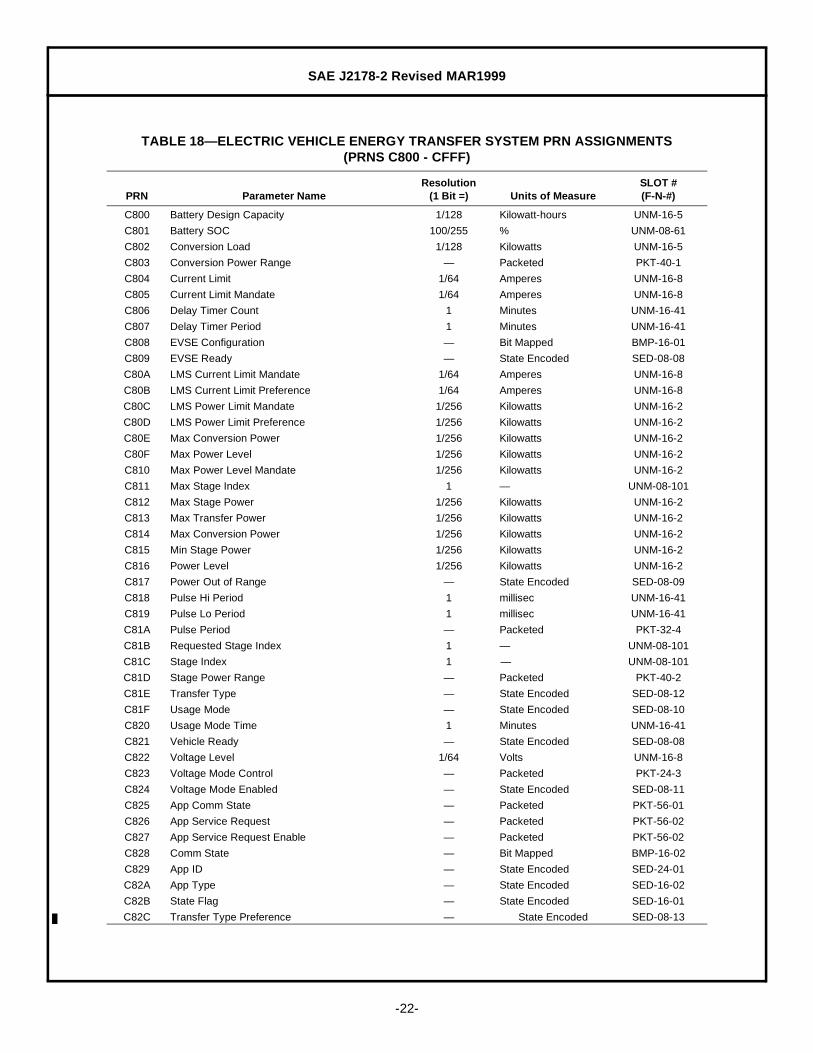
TABLE 18— ELECTRIC VEHICLE ENERGY TRANSFER SYSTEM PRN ASSIGNMENTS(PRNS C800 - CFFF)
PRN Parameter NameResolution
(1 Bit =) Units of MeasureSLOT #(F-N-#)
C800 Battery Design Capacity 1/128 Kilowatt-hours UNM-16-5
C801 Battery SOC 100/255 % UNM-08-61
C802 Conversion Load 1/128 Kilowatts UNM-16-5
C803 Conversion Power Range — Packeted PKT-40-1
C804 Current Limit 1/64 Amperes UNM-16-8
C805 Current Limit Mandate 1/64 Amperes UNM-16-8
C806 Delay Timer Count 1 Minutes UNM-16-41
C807 Delay Timer Period 1 Minutes UNM-16-41
C808 EVSE Configuration — Bit Mapped BMP-16-01
C809 EVSE Ready — State Encoded SED-08-08
C80A LMS Current Limit Mandate 1/64 Amperes UNM-16-8
C80B LMS Current Limit Preference 1/64 Amperes UNM-16-8
C80C LMS Power Limit Mandate 1/256 Kilowatts UNM-16-2
C80D LMS Power Limit Preference 1/256 Kilowatts UNM-16-2
C80E Max Conversion Power 1/256 Kilowatts UNM-16-2
C80F Max Power Level 1/256 Kilowatts UNM-16-2
C810 Max Power Level Mandate 1/256 Kilowatts UNM-16-2
C811 Max Stage Index 1 — UNM-08-101
C812 Max Stage Power 1/256 Kilowatts UNM-16-2
C813 Max Transfer Power 1/256 Kilowatts UNM-16-2
C814 Max Conversion Power 1/256 Kilowatts UNM-16-2
C815 Min Stage Power 1/256 Kilowatts UNM-16-2
C816 Power Level 1/256 Kilowatts UNM-16-2
C817 Power Out of Range — State Encoded SED-08-09
C818 Pulse Hi Period 1 millisec UNM-16-41
C819 Pulse Lo Period 1 millisec UNM-16-41
C81A Pulse Period — Packeted PKT-32-4
C81B Requested Stage Index 1 — UNM-08-101
C81C Stage Index 1 — UNM-08-101
C81D Stage Power Range — Packeted PKT-40-2
C81E Transfer Type — State Encoded SED-08-12
C81F Usage Mode — State Encoded SED-08-10
C820 Usage Mode Time 1 Minutes UNM-16-41
C821 Vehicle Ready — State Encoded SED-08-08
C822 Voltage Level 1/64 Volts UNM-16-8
C823 Voltage Mode Control — Packeted PKT-24-3
C824 Voltage Mode Enabled — State Encoded SED-08-11
C825 App Comm State — Packeted PKT-56-01
C826 App Service Request — Packeted PKT-56-02
C827 App Service Request Enable — Packeted PKT-56-02
C828 Comm State — Bit Mapped BMP-16-02
C829 App ID — State Encoded SED-24-01
C82A App Type — State Encoded SED-16-02
C82B State Flag — State Encoded SED-16-01
C82C Transfer Type Preference — State Encoded SED-08-13
SAE J2178-2 Revised MAR1999
-23-
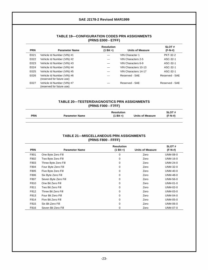
TABLE 19— CONFIGURATION CODES PRN ASSIGNMENTS(PRNS E000 - E7FF)
PRN Parameter NameResolution
(1 Bit =) Units of MeasureSLOT #(F-N-#)
E021 Vehicle Id Number (VIN) #1 — VIN Character 1 PKT-32-2
E022 Vehicle Id Number (VIN) #2 — VIN Characters 2-5 ASC-32-1
E023 Vehicle Id Number (VIN) #3 — VIN Characters 6-9 ASC-32-1
E024 Vehicle Id Number (VIN) #4 — VIN Characters 10-13 ASC-32-1
E025 Vehicle Id Number (VIN) #5 — VIN Characters 14-17 ASC-32-1
E026 Vehicle Id Number (VIN) #6 (reserved for future use)
— Reserved - SAE Reserved - SAE
E027 Vehicle Id Number (VIN) #7(reserved for future use)
— Reserved - SAE Reserved - SAE
TABLE 20— TESTER/DIAGNOSTICS PRN ASSIGNMENTS(PRNS F000 - F7FF)
PRN Parameter NameResolution
(1 Bit =) Units of MeasureSLOT #(F-N-#)
TABLE 21— MISCELLANEOUS PRN ASSIGNMENTS(PRNS F800 - FFFF)
PRN Parameter NameResolution
(1 Bit =) Units of MeasureSLOT #(F-N-#)
F801 One Byte Zero Fill 0 Zero UNM-08-0
F802 Two Byte Zero Fill 0 Zero UNM-16-0
F803 Three Byte Zero Fill 0 Zero UNM-24-0
F804 Four Byte Zero Fill 0 Zero UNM-32-0
F805 Five Byte Zero Fill 0 Zero UNM-40-0
F806 Six Byte Zero Fill 0 Zero UNM-48-0
F807 Seven Byte Zero Fill 0 Zero UNM-56-0
F810 One Bit Zero Fill 0 Zero UNM-01-0
F811 Two Bit Zero Fill 0 Zero UNM-02-0
F812 Three Bit Zero Fill 0 Zero UNM-03-0
F813 Four Bit Zero Fill 0 Zero UNM-04-0
F814 Five Bit Zero Fill 0 Zero UNM-05-0
F815 Six Bit Zero Fill 0 Zero UNM-06-0
F816 Seven Bit Zero Fill 0 Zero UNM-07-0

SAE J2178-2 Revised MAR1999
-24-
9. Scaling, Limit, Offset, and Transfer Function (SLOT) Definitions— This section defines the parameterscaling, limit(s), offset value, and transfer function for bit, byte, or larger variables. These SLOT definitionshave been grouped together to avoid duplication in this document and to offer a common list of definitions foruse in assigning new parameter definitions. The wide range of these definitions is expected to cover a largenumber of applications, and should be used for most new definitions as well. Each of these definitions hasbeen assigned a SLOT number for reference purposes but is formatted to include a three letter mnemonicrepresenting the format, the parameter length in bits, followed by a random sequence number.
The transfer function is shown in two forms to allow use in implementing messages in modules and ininterpreting messages found on a network. The two forms are identical but are solved for each of the twovariables. The transfer function defines the relationship between computer units (N) in decimal, andengineering units (E) of the data.
The format of the SLOT, identified by the three letter mnemonic, indicates the category of bit representation.These formats include:
Multiple Parameter Packeted PKTBit Mapped with Mask BMMBit Mapped without Mask BMPUnsigned Numeric UNM2’s Complement Signed Numeric SNMState Encoded SEDASCII Encoded ASCBinary Coded Decimal (BCD) BCDSigned Floating Point (Scientific Notation) SFP
These formats are described in the following paragraphs.
9.1 Multiple Parameter Packeted (PKT) SLOTs— The multiple parameter packet is used to define PRNs whichrefer to more than one parameter as a group that are related. By grouping multiple parameters, the efficiencyof utilization can be improved, if the groupings are accomplished such that the individual parameters that needto be associated with each other are transmitted together. These packets are defined as a sequence of otherPRN numbers, in the order that they appear in the message (MSB first). In some cases, a PRN may beassigned to fill bits or bytes with zeros. Each zero fill PRN is an unsigned numeric SLOT with zero as thesequence number.
9.1.1 MUTLIPLE PARAMETER PACKETED ASSIGNMENTS
PKT-08-1 Transmission Gear and Lockup Status (PRN 1805)MSB PRN 1807 Transmission Lockup Status 2 bitsLSB PRN 1808 Transmission Gear Engaged 6 bits
PKT-08-2 Transmission Gear and Lockup Status - Expanded (PRN 180F)MSB PRN 1807 Transmission Lockup Status 2 bitsLSB PRN 1810 Transmission Gear Engaged - Expanded 6 bits
PKT-16-1 Trouble Code that Caused Freeze Frame Storage (PRN 0002)MSB PRN 1005 Sub-System Category 2 bits
PRN 1006 MSB of Trouble Code 2 bitsLSB PRN 1007 Lower Bytes of Trouble Code - BCD 12 bits
PKT-16-2 Fuel System Status (PRN 0003)MSB PRN 1008 Fuel System Status - Bank 1 8 bitsLSB PRN 1009 Fuel System Status - Bank 2 8 bits
SAE J2178-2 Revised MAR1999
-25-
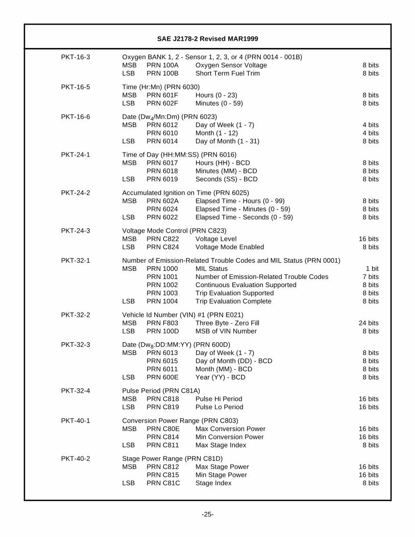
PKT-16-3 Oxygen BANK 1, 2 - Sensor 1, 2, 3, or 4 (PRN 0014 - 001B)MSB PRN 100A Oxygen Sensor Voltage 8 bitsLSB PRN 100B Short Term Fuel Trim 8 bits
PKT-16-5 Time (Hr:Mn) (PRN 6030)MSB PRN 601F Hours (0 - 23) 8 bitsLSB PRN 602F Minutes (0 - 59) 8 bits
PKT-16-6 Date (Dw4/Mn:Dm) (PRN 6023)MSB PRN 6012 Day of Week (1 - 7) 4 bits
PRN 6010 Month (1 - 12) 4 bitsLSB PRN 6014 Day of Month (1 - 31) 8 bits
PKT-24-1 Time of Day (HH:MM:SS) (PRN 6016)MSB PRN 6017 Hours (HH) - BCD 8 bits
PRN 6018 Minutes (MM) - BCD 8 bitsLSB PRN 6019 Seconds (SS) - BCD 8 bits
PKT-24-2 Accumulated Ignition on Time (PRN 6025)MSB PRN 602A Elapsed Time - Hours (0 - 99) 8 bits
PRN 6024 Elapsed Time - Minutes (0 - 59) 8 bitsLSB PRN 6022 Elapsed Time - Seconds (0 - 59) 8 bits
PKT-24-3 Voltage Mode Control (PRN C823)MSB PRN C822 Voltage Level 16 bitsLSB PRN C824 Voltage Mode Enabled 8 bits
PKT-32-1 Number of Emission-Related Trouble Codes and MIL Status (PRN 0001)MSB PRN 1000 MIL Status 1 bit
PRN 1001 Number of Emission-Related Trouble Codes 7 bitsPRN 1002 Continuous Evaluation Supported 8 bitsPRN 1003 Trip Evaluation Supported 8 bits
LSB PRN 1004 Trip Evaluation Complete 8 bits
PKT-32-2 Vehicle Id Number (VIN) #1 (PRN E021)MSB PRN F803 Three Byte - Zero Fill 24 bitsLSB PRN 100D MSB of VIN Number 8 bits
PKT-32-3 Date (Dw8:DD:MM:YY) (PRN 600D)MSB PRN 6013 Day of Week (1 - 7) 8 bits
PRN 6015 Day of Month (DD) - BCD 8 bitsPRN 6011 Month (MM) - BCD 8 bits
LSB PRN 600E Year (YY) - BCD 8 bits
PKT-32-4 Pulse Period (PRN C81A)MSB PRN C818 Pulse Hi Period 16 bitsLSB PRN C819 Pulse Lo Period 16 bits
PKT-40-1 Conversion Power Range (PRN C803)MSB PRN C80E Max Conversion Power 16 bits
PRN C814 Min Conversion Power 16 bitsLSB PRN C811 Max Stage Index 8 bits
PKT-40-2 Stage Power Range (PRN C81D)MSB PRN C812 Max Stage Power 16 bits
PRN C815 Min Stage Power 16 bitsLSB PRN C81C Stage Index 8 bits

SAE J2178-2 Revised MAR1999
-26-
PKT-56-1 App Comm State (PRN C825)MSB PRN C82A App Type 16 bits
PRN C829 App ID 24 bitsLSB PRN C828 Comm State 16 bits
PKT-56-2 App Service Request (PRN C826)App Service Request Enable (PRN C827)MSB PRN C82A App Type 16 bits
PRN C829 App ID 24 bitsLSB PRN C82B State Flag 16 bits
9.2 Bit Mapped Without Mask (BMP) SLOTs— Bit mapped (BMP) SLOTs are used to encode data that typicallycontains several binary parameters, such as status bits or flags, grouped into a single byte or several bytes.Bit mapped SLOTs can also be used for discrete output control such as warning lamps where each bit wouldindicate the state of a particular lamp. The data in these bit mapped SLOTs is not followed by a MASK byte.There can be up to 4 bytes of data without a mask.
9.2.1 BIT MAPPED WITHOUT MASK PARAMETER ASSIGNMENTS
BMP-01-1 MIL Status (PRN 1000)
Length: 1 Bit 0 1
MSB Item 1: Malfunction Indicator Lamp (MIL) Not Commanded On Commanded On
BMP-08-1 Continuous Evaluation Supported (PRN 1002)
Length: 8 bits 0 1
MSB Item 1: Not UsedItem 2: Not UsedItem 3: Not UsedItem 4: Not UsedItem 5: Not UsedItem 6: Comprehensive Component Monitoring Not Supported SupportedItem 7: Fuel System Monitoring Not Supported Supported
LSB Item 8: Misfire Monitoring Not Supported Supported
BMP-08-2 Trip Evaluation Supported (PRN 1002)
Length: 8 bits 0 1
MSB Item 1: EGR System Not Supported SupportedItem 2: Oxygen Sensor Heater Not Supported SupportedItem 3: Oxygen Sensor Not Supported SupportedItem 4: A/C System Refrigerant Not Supported SupportedItem 5: Secondary Air System Not Supported SupportedItem 6: Evaporative Purge System Not Supported SupportedItem 7: Heated Catalyst Not Supported Supported
LSB Item8: Catalyst Not Supported Supported

SAE J2178-2 Revised MAR1999
-27-
BMP-08-3 Trip Evaluation Complete (PRN 1004)
Length: 8 bits 0 1
MSB Item 1: EGR System Test Complete Test Not CompleteItem 2: Oxygen Sensor Heater Test Complete Test Not CompleteItem 3: Oxygen Sensor Test Complete Test Not CompleteItem 4: A/C System Refrigerant Test Complete Test Not CompleteItem 5: Secondary Air System Test Complete Test Not CompleteItem 6: Evaporative Purge System Test Complete Test Not CompleteItem 7: Heated Catalyst Test Complete Test Not Complete
LSB Item 8: Catalyst Test Complete Test Not Complete
BMP-08-4 Fuel System Status (PRN 1008 and 1009)
Length: 8 bits 0 1
MSB Item 1: ReservedItem 2: ReservedItem 3: ReservedItem 4: Closed Loop, Faulty O2 Sensor False TrueItem 5: Open Loop, Detected Fault False TrueItem 6: Open Loop, Driving Conditions False TrueItem 7: Closed Loop, Using O2 Sensor False True
LSB Item 8: Open Loop, Not Ready for Closed False True
BMP-08-05 Commanded Secondary Air Status (PRN 0012)
Length: 8 bits 0 1
MSB Item 1: ReservedItem 2: ReservedItem 3: ReservedItem 4: ReservedItem 5: ReservedItem 6: Atmosphere / Off Not Supported SupportedItem 7: Downstream— First Catalyst Not Supported Supported
LSB Item 8: Upstream— First Catalyst Not Supported Supported
BMP-08-6 O2 Sensor Location (PRN 0013)
Length: 8 bits 0 1
MSB Item 1:8 Bank 2— Sensor 4 (B2-S4) Not Present PresentItem 2: Bank 2— Sensor 3 (B2-S3) Not Present PresentItem 3: Bank 2— Sensor 2 (B2-S2) Not Present PresentItem 4: Bank 2— Sensor 1 (B2-S1) Not Present PresentItem 5: Bank 1— Sensor 4 (B1-S4) Not Present PresentItem 6: Bank 1— Sensor 3 (B2-S3) Not Present PresentItem 7: Bank 1— Sensor 2 (B1-S2) Not Present Present
LSB Item 8: Bank 1— Sensor 1 (B1-S1) Not Present Present

SAE J2178-2 Revised MAR1999
-28-
BMP-08-7 Lamp Status (PRN 604D)
Length: 8 bits 0 1
MSB Item 1: Display Brightness Mode Off OnItem 2: Park Lamps Off OnItem 3: Low Beam Headlamps Off OnItem 4: High Beam Headlamps Off OnItem 5: Daytime Running Lamps Off OnItem 6: Electronic Displays Off OnItem 7: Front Fog Lamps Off On
LSB Item 8: Rear Fog Lamps Off On
BMP-08-8 MIL Lamp Data (PRN 1017)
Length: 8 bits 0 1
MSB Item 1: Malfunction Indicator Lamp Off OnItem 2: Display Trouble Code False TrueItem 3: Misfire Detected False TrueItem 4: ReservedItem 5: ReservedItem 6: ReservedItem 7: Reserved
LSB Item 8: Reserved
BMP-16-01 EVSE Configuration (PRN C808)
Length: 16 Bits 0 1
Byte 1:MSB Item 1: AC Energy Transfer Not Supported Supported
Item 2: Inductive Energy Transfer Not Supported SupportedItem 3: DC Energy Transfer Not Supported SupportedItem 4: Positive Pulse Mode Not Supported SupportedItem 5: Voltage Mode Not Supported SupportedItem 6: ReservedItem 7: Reserved
LSB Item 8: Reserved
Byte 2:MSB Item 9: Reserved
Item 10: ReservedItem 11: ReservedItem 12: ReservedItem 13: ReservedItem 14: ReservedItem 15: Reserved
LSB Item 16: Reserved
SAE J2178-2 Revised MAR1999
-29-
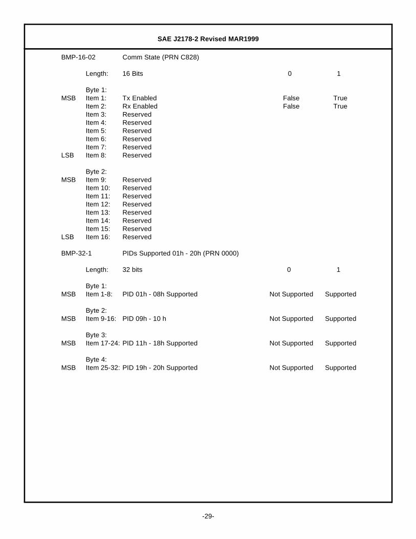
BMP-16-02 Comm State (PRN C828)
Length: 16 Bits 0 1
Byte 1:MSB Item 1: Tx Enabled False True
Item 2: Rx Enabled False TrueItem 3: ReservedItem 4: ReservedItem 5: ReservedItem 6: ReservedItem 7: Reserved
LSB Item 8: Reserved
Byte 2:MSB Item 9: Reserved
Item 10: ReservedItem 11: ReservedItem 12: ReservedItem 13: ReservedItem 14: ReservedItem 15: Reserved
LSB Item 16: Reserved
BMP-32-1 PIDs Supported 01h - 20h (PRN 0000)
Length: 32 bits 0 1
Byte 1:MSB Item 1-8: PID 01h - 08h Supported Not Supported Supported
Byte 2:MSB Item 9-16: PID 09h - 10 h Not Supported Supported
Byte 3:MSB Item 17-24: PID 11h - 18h Supported Not Supported Supported
Byte 4:MSB Item 25-32: PID 19h - 20h Supported Not Supported Supported

SAE J2178-2 Revised MAR1999
-30-
BMP-32-2 PIDs Supported 21 h - 40h (PRN 0020)
Length: 32 bits 0 1
Byte 1:MSB Item 1-8: PID 21h - 28h Supported Not Supported Supported
Byte 2:MSB Item 9-16: PID 29h - 30h Supported Not Supported Supported
Byte 3:MSB Item 17-24: PID 31h - 38h Supported Not Supported Supported
Byte 4:
MSB Item 25-32: PID 39h - 40 h Supported Not Supported Supported
BMP-32-3 PIDs Supported 41h - 60h (PRN 0040)
Length: 32 bits 0 1
Byte 1:MSB Item 1-8: PID 41h - 48h Supported Not Supported Supported
Byte 2:MSB Item 9-16: PID 49h - 50h Supported Not Supported Supported
Byte 3:MSB Item 17-24: PID 51h - 58h Supported Not Supported Supported
Byte 4:MSB Item 25-32: PID 59h - 60h Supported Not Supported Supported
9.3 Bit Mapped With Mask Bytes (BMM) SLOTs— Bit mapped with mask (BMM) SLOTs are used to encodedata that typically contains several binary parameters, such as status bits or flags, grouped into a single byte orseveral bytes. Bit mapped SLOTs can also be used for discrete output control such as warning lamps whereeach bit would indicate the state of a particular lamp. The data in these bit mapped SLOTs are alwaysfollowed by a MASK byte which is used to indicate which bits of the data byte are valid. There can be up to 4bytes of data including the mask bytes. Valid combinations include up to 2 data bytes each with mask.
9.3.1 BIT MAPPED WITH MASK PARAMETER ASSIGNMENTS— None Defined
9.4 Unsigned Numeric (UNM) SLOTs— Unsigned numeric (UNM) SLOTs are used to encode data that istypically associated with information such as temperature, speed, or percent. The SLOT can be 8, 16, 24, ...56 bits in length (1 to 7 bytes) and may or may not have an offset. Unsigned number SLOTs can also be usedfor sequential data such as month (1-12) or day of month (1-31). Each SLOT definition contains a field for:resolution per bit; minimum and maximum value; and transfer function. The transfer function defines therelationship between computer units (N) in decimal, and engineering units (E) of the data.

SAE J2178-2 Revised MAR1999
-31-
9.4.1 UNSIGNED NUMERIC VARIABLE ASSIGNMENTS— The unsigned numeric variables have been grouped asfollows:
Table 22— ZEROs SLOT assignmentsTable 23— UNM-xx, Short (< 8 Bit) SLOTsTable 24— UNM-08, 8 Bit SLOT AssignmentsTable 25— UNM-16, 16 Bit SLOT AssignmentsTable 26— UNM-24, 24 Bit SLOT AssignmentsTable 27— UNM-32, 32 Bit SLOT Assignments
TABLE 22— ZEROs SLOT ASSIGNMENTS
SLOT # Description Length
UNM-01-0 Zero (0) 1 Bit
UNM-02-0 Zero (0) 2 Bits
UNM-03-0 Zero (0) 3 Bits
UNM-04-0 Zero (0) 4 Bits
UNM-05-0 Zero (0) 5 Bits
UNM-06-0 Zero (0) 6 Bits
UNM-07-0 Zero (0) 7 Bits
UNM-08-0 Zero (0) 8 Bits
UNM-16-0 Zero (0) 16 Bits
UNM-24-0 Zero (0) 24 Bits
UNM-32-0 Zero (0) 32 Bits
UNM-40-0 Zero (0) 40 Bits
UNM-48-0 Zero (0) 48 Bits
UNM-56-0 Zero (0) 56 Bits
TABLE 23— UNM-xx, Short (<8 Bit) SLOTs
SLOT#
Scaling(Resolution;
1 Bit =)Minimum
LimitMaximum
LimitInvalidRange
TransferFunction
N =
TransferFunction
E =Comment
01-1 1 0 1 — E N —
02-1 1 0 3 — E N —
03-1 1 0 7 — E N —
04-1 1 0 15 — E N —
05-1 1 0 31 — E N —
06-1 1 0 63 — E N —
07-1 1 0 127 — E N —
SAE J2178-2 Revised MAR1999
-32-
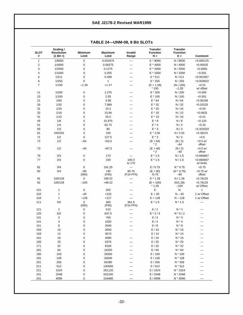
TABLE 24— UNM-08, 8 Bit SLOTs
SLOT#
Scaling /Resolution
(1 Bit =)Minimum
LimitMaximum
LimitInvalidRange
TransferFunction
N =
TransferFunction
E = Comment
1 1/8000 0 0.031875 — E * 8000 N / 8000 =0.0001252 1/4000 0 0.06375 — E * 4000 N / 4000 =0.000253 1/2000 0 0.1275 — E * 2000 N / 2000 =0.00054 1/1000 0 0.255 — E * 1000 N / 1000 =0.0015 1/511 0 0.499 — E * 511 N / 511 =0.0019576 1/255 0 1 — E * 255 N / 255 =0.0039227 1/100 –1.28 +1.27 — (E + 1.28)
* 100(N / 100)
–1.28=0.01
w/ offset11 1/200 0 1.275 — E * 200 N / 200 =0.00515 1/100 0 2.55 — E * 100 N / 100 =0.00121 1/64 0 3.98 — E * 64 N / 64 =0.0015626 1/32 0 7.969 — E * 32 N / 32 =0.0312531 1/25 0 10.2 — E * 25 N / 16 =0.0432 1/16 0 15.94 — E * 16 N / 13 =0.062541 1/10 0 25.5 — E * 10 N / 10 =0.0145 1/8 0 31.875 — E * 8 N / 8 =0.12551 1/4 0 63.75 — E * 4 N / 4 =0.2555 1/3 0 85 — E * 3 N / 3 =0.33333361 100/255 0 100 — E * 2.55 N / 2.55 =0.3921571 1/2 0 127.5 — E * 2 N / 2 =0.572 1/2 –64 +63.5 — (E + 64)
* 2(N / 2)
–64=0.5 w/offset
73 1/2 –40 +87.5 — (E + 40)* 2
(N / 2)–40
=0.5 w/offset
76 2/3 0 170 — E * 1.5 N / 1.5 =0.66666777 2/3 0 100 100.3
to 170E * 1.5 N / 1.5 =0.666667
w/ limits81 3/4 0 191.25 — E / 0.75 N * 0.75 =0.7582 3/4 –90
(00h)+90
(F0h)90.75
(F1h-FFh)(E + 90)
/0.75(N * 0.75)
–90=0.75 w/
offset91 100/128 0 199.22 — E * 1.28 N / 1.28 =0.7812592 100/128 –100 +99.22 — (E + 100)
* 1.28(N/1.28)
–100=0.78125w/ Offset
101 1 0 255 — E N 1102 1 –40 +215 — E + 40 N – 40 1 w/ Offset104 1 –128 +127 — E + 128 N – 128 1 w/ Offset111 3/2 0
(00h)360
(F0h)361.5
(F1h-FFh)E * 1.5 N * 1.5 —
121 2 0 510 — E / 2 N * 2 —125 5/2 0 637.5 — E * 2 / 5 N * 5 / 2 —131 3 0 765 — E / 3 N * 3 —141 4 0 1020 — E / 4 N * 4 —151 8 0 2040 — E / 8 N * 8 —155 10 0 2550 — E / 10 N * 10 —159 14 0 3570 E / 14 N * 14 —161 16 0 4080 — E / 16 N * 16 —165 25 0 6375 — E / 25 N * 25 —171 32 0 8160 — E / 32 N * 32 —181 64 0 16320 — E / 64 N * 64 —185 100 0 25500 — E / 100 N * 100 —191 128 0 32640 — E / 128 N * 128 —201 256 0 65280 — E / 256 N * 256 —211 512 0 130560 — E / 512 N * 512 —221 1024 0 261120 — E / 1024 N * 1024 —231 2048 0 522240 — E / 2048 N * 2048 —241 4096 0 104480 — E / 4096 N * 4096 —
SAE J2178-2 Revised MAR1999
-33-
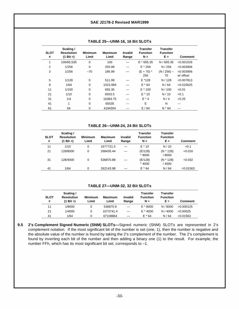
9.5 2’s Complement Signed Numeric (SNM) SLOTs— Signed numeric (SNM) SLOTs are represented in 2’scomplement notation. If the most significant bit of the number is set (one, 1), then the number is negative andthe absolute value of the number is found by taking the 2’s complement of the number. The 2’s complement isfound by inverting each bit of the number and then adding a binary one (1) to the result. For example, thenumber FFh, which has its most significant bit set, corresponds to –1.
TABLE 25— UNM-16, 16 Bit SLOTs
SLOT#
Scaling /Resolution
(1 Bit =)Minimum
LimitMaximum
LimitInvalidRange
TransferFunction
N =
TransferFunction
E = Comment
1 100/65,535 0 100 — E * 655.35 N / 655.35 =0.001526
2 1/256 0 255.99 — E * 256 N / 256 =0.003906
3 1/256 –70 185.99 — (E + 70) *256
(N / 256) – 70
=0.003906w/ offset
5 1/128 0 511.99 — E *128 N / 128 =0.007813
8 1/64 0 1023.984 — E * 64 N / 64 =0.015625
11 1/100 0 655.35 — E * 100 N / 100 =0.01
21 1/10 0 6553.5 — E * 10 N / 10 =0.1
31 1/4 0 16383.75 — E * 4 N / 4 =0.25
41 1 0 65535 — E N —
61 64 0 4194304 — E / 64 N * 64 —
TABLE 26— UNM-24, 24 Bit SLOTS
SLOT#
Scaling /Resolution
(1 Bit =)Minimum
LimitMaximum
LimitInvalidRange
TransferFunction
N =
TransferFunction
E = Comment
11 1/10 0 1677721.5 — E * 10 N / 10 =0.1
21 128/8000 0 268435.44 — (E/128)* 8000
(N * 128)/ 8000
=0.016
31 128/4000 0 536870.88 — (E/128)* 4000
(N * 128)/ 4000
=0.032
41 1/64 0 262143.98 — E * 64 N / 64 =0.01563
TABLE 27— UNM-32, 32 Bit SLOTs
SLOT#
Scaling /Resolution
(1 Bit =)Minimum
LimitMaximum
LimitInvalidRange
TransferFunction
N =
TransferFunction
E = Comment
11 1/8000 0 536870.9 — E * 8000 N / 8000 =0.000125
21 1/4000 0 1073741.4 — E * 4000 N / 4000 =0.00025
41 1/64 0 67108864 — E * 64 N / 64 =0.01563

SAE J2178-2 Revised MAR1999
-34-
9.5.1 2’S COMPLEMENT SIGNED NUMERIC VARIABLE ASSIGNMENTS— The 2’s complement signed numeric variablesare grouped as follows:
9.6 State Encoded (SED) SLOTs— State enclosed (SED) SLOTs are used for data that can take one of severalstates such as Day of Week or Wiper Mode. Each SLOT definition contains a field for describing each statewithin the SLOT. There can be between 1 and 8 bits in any given SLOT with 2n possible states where n is thenumber of bits in the SLOT.
9.6.1 STATE ENCODED VARIABLE ASSIGNMENTS
SED-02-1 Sub-System Category Reference Letter (PRN 1005)
Length: 2 bits (0 - 3)
0 “P” = Powertrain1 “C” = Chassis2 “B” = Body3 “U” = Undefined
SED-02-2 Most Significant Digit of Trouble Code (PRN 1006)
Length: 2 bits (0 - 3)
0 “0”1 “1”2 “2”3 “3”
SED-02-3 Transmission Lock-up Status (PRN 1807)
Length: 2 bits (0 - 3)
0 Unlock1 Partial Lock2 Full Lock3 Invalid
TABLE 28— SNM-08, 8 Bit SLOTs
SLOT#
Scaling /Resolution
(1 Bit =)Minimum
LimitMaximum
LimitInvalidRange
TransferFunction
N =
TransferFunction
E = Comment
11 1/2 –64 +63.5 — E * 2 N / 2 =0.5
21 1 –128 +127 — E N —
41 4 –512 +508 — E / 4 N * 4 —
51 3/2 –192 +190.5 — E * 2/3 N * 3/2 —
61 6 –768 +762 — E / 6 N * 6 —

SAE J2178-2 Revised MAR1999
-35-
SED-04-1 Day of the Week (PRN 6012)
Length: 4 bits (0 - F)
0 Unknown1 Sunday2 Monday3 Tuesday4 Wednesday5 Thursday6 Friday7 Saturday8 - F Invalid
SED-04-2 Month (PRN 6010)
Length: 4 bits (0 - F)
0 Unknown1 January2 February3 March4 April5 May6 June7 July8 August9 SeptemberA OctoberB NovemberC DecemberD - F Invalid
SED-06-1 Transmission Gear Engaged (PRN 1808)
Length: 6 bits (00 - 3F)
00 Neutral01 Reverse02 Forward 104 Forward 208 Forward 310 Forward 420 Forward 5Others Invalid

SAE J2178-2 Revised MAR1999
-36-
SED-06-2 Transmission Gear Engaged— Expanded (PRN 1810)
Length: 6 bits (00 - 3F)
00 Unknown01 Neutral02-0F Reserved10 Reverse11-1F Reserved for Reverse Gears20 Forward 121 Forward 222 Forward 323 Forward 424 Forward 525 Forward 626-2F Reserved for Forward Gears30-3E Reserved3F Invalid
SED-08-1 Wiper Mode (PRN A003)
Length: 8 bits (00 - FF)
00 Invalid01 Off02 Intermittent03 Low Speed04 Medium Speed05 High Speed06 Pulse07 - FF Invalid
SED-08-2 Day of the Week (PRN 6013)
Length: 8 bits (00 - FF)
00 Unknown01 Sunday02 Monday03 Tuesday04 Wednesday05 Thursday06 Friday07 Saturday08 - FF Invalid

SAE J2178-2 Revised MAR1999
-37-
SED-08-3 Day of Month (PRN 6014)
Length: 8 bits (00 - FF)
00 Invalid01 1st
02 2nd
03 3rd
04 4th
05 5th
06 6th
07 7th
08 8th
09 9th
0A 10th
0B 11th
0C 12th
0D 13th
0E 14th
0F 15th
10 16th
11 17th
12 18th
13 19th
14 20th
15 21th
16 22nd
17 23rd
18 24th
19 25th
1A 26th
1B 27th
1C 28th
1D 29th
1E 30th
1F 31st
20 - FF Invalid
SED-08-4 Transmission Range (PRN 1806, 1809, 180d, and 180e)
Length: 8 bits (00 - FF)
00 Unknown01 Reverse02 Forward 104 Forward 208 Forward 310 Forward 420 Forward 540 Forward 6 / Park80 NeutralOthers Invalid
SAE J2178-2 Revised MAR1999
-38-
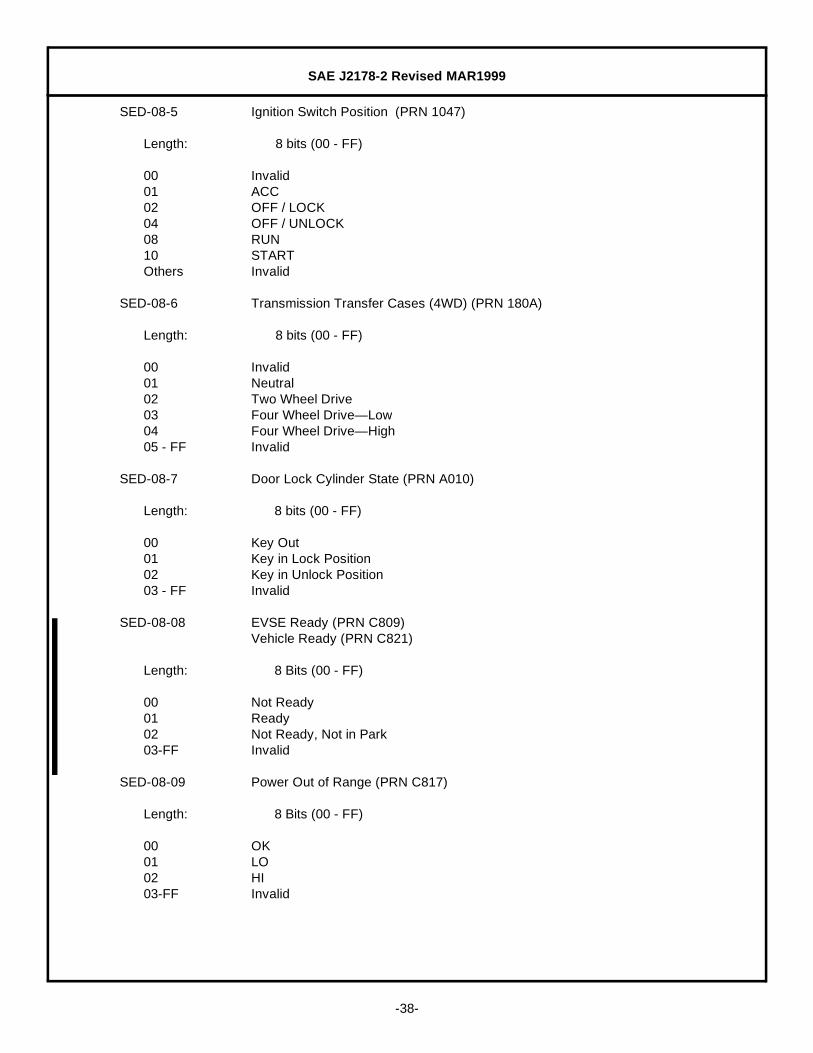
SED-08-5 Ignition Switch Position (PRN 1047)
Length: 8 bits (00 - FF)
00 Invalid01 ACC02 OFF / LOCK04 OFF / UNLOCK08 RUN10 STARTOthers Invalid
SED-08-6 Transmission Transfer Cases (4WD) (PRN 180A)
Length: 8 bits (00 - FF)
00 Invalid01 Neutral02 Two Wheel Drive03 Four Wheel Drive— Low04 Four Wheel Drive— High05 - FF Invalid
SED-08-7 Door Lock Cylinder State (PRN A010)
Length: 8 bits (00 - FF)
00 Key Out01 Key in Lock Position02 Key in Unlock Position03 - FF Invalid
SED-08-08 EVSE Ready (PRN C809)Vehicle Ready (PRN C821)
Length: 8 Bits (00 - FF)
00 Not Ready01 Ready02 Not Ready, Not in Park03-FF Invalid
SED-08-09 Power Out of Range (PRN C817)
Length: 8 Bits (00 - FF)
00 OK01 LO02 HI03-FF Invalid

SAE J2178-2 Revised MAR1999
-39-
SED-08-10 Usage Mode (PRN C81F)
Length: 8 Bits (00 - FF)
00 No Transfer01 Base02 Over03 Support04-FF Invalid
SED-08-11 Voltage Mode Enabled (PRN C824)
Length: 8 Bits (00 - FF)
00 False01 True02-FF Invalid
SED-08-12 Transfer Type (PRN C81E)
Length: 8 bits (00 - FF)
00 No Transfer01 AC02 Inductive03 DC04 - FF Invalid
SED-08-13 Transfer Type Preference (PRN C82C)
Length: 8 bits
00 No Preference01 AC02 Inductive03 DC04 - FF Invalid
SED-16-01 State Flag (PRN C82B)
Length: 16 Bits (0000 - FFFF)
0000 False0001 True0002-FFFF Reserved

SAE J2178-2 Revised MAR1999
-40-
SED-16-02 App Type (PRN C82A)
Length: 16 Bits (0000 - FFFF)
0000 All Applications0001 SAE0002 Chrysler0003 Ford0004 GM0005 Reserved SAE
Remaining values assigned to EV and EVSE manufacturers who request an App Type ID.
SED-24-01 App ID (PRN C829)
Length: 24 Bits (000000 - FFFFFF)
000000 All Applications000001 SAE J2293 ETS000002 - FFFFFF Reserved
These ID values apply to messages with an SAE App Type.
9.7 ASCII Encoded (ASC) SLOTs— ASCII (ASC) SLOTs are used to encode ASCCI data. The least significant7 bits represent the standard ASCII codes from 0 to 127. The most significant bit is reserved at this time butmay be assigned a special function in the future. Several ASCII characters can be included in a singlemessage by placing up to 7 ASCII characters sequentially in the data field. This allows a character string of upto 7 characters to be sent in a single message.
The ASCII character set is included in Table 29.
9.7.1 ASCII ENCODED VARIABLE ASSIGNMENTS
ASC-08-1 One ASCII Character
Length: 8 bits
Byte 1: One ASCII Character
ASC-16-1 Two ASCII Characters
Length: 16 bits
Byte 1: Left Most CharacterByte 2: Right Most Character
ASC-24-1 Three ASCII Characters
Length: 24 bits
Byte 1: Left Most CharacterByte 2: Middle CharacterByte 3: Right Most Character

SAE J2178-2 Revised MAR1999
-41-
ASC-32-1 Four ASCII Characters
Length: 32 bits
Byte 1: Left Most CharacterByte 2: Middle Left CharacterByte 3: Middle Right CharacterByte 4: Right Most Character
ASC-40-1 Five ASCII Characters
Length: 40 bits
Byte 1: Left Most CharacterByte 2: Middle Left CharacterByte 3: Middle CharacterByte 4: Middle Right CharacterByte 5: Right Most Character
ASC-48-1 Six ASCII Characters
Length: 48 bits
Byte 1: Left Most CharacterByte 2: Middle Left CharacterByte 3: Middle Middle Left CharacterByte 4: Middle Middle Right CharacterByte 5: Middle Right CharacterByte 6: Right Most Character
ASC-56-1 Seven ASCII Characters
Length: 56 bits
Byte 1: Left Most CharacterByte 2: Middle Left CharacterByte 3: Middle Middle Left CharacterByte 4: Middle CharacterByte 5: Middle Middle Right CharacterByte 6: Middle Right CharacterByte 7: Right Most Character
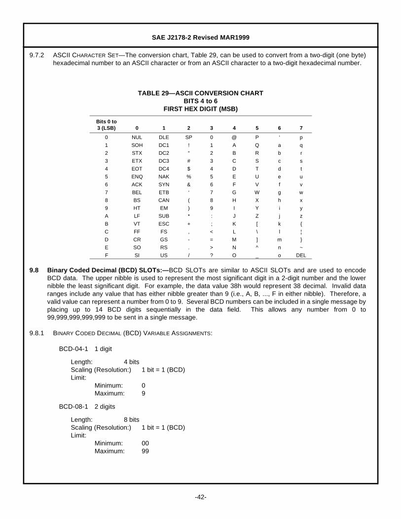
SAE J2178-2 Revised MAR1999
-42-
9.7.2 ASCII CHARACTER SET— The conversion chart, Table 29, can be used to convert from a two-digit (one byte)hexadecimal number to an ASCII character or from an ASCII character to a two-digit hexadecimal number.
9.8 Binary Coded Decimal (BCD) SLOTs:— BCD SLOTs are similar to ASCII SLOTs and are used to encodeBCD data. The upper nibble is used to represent the most significant digit in a 2-digit number and the lowernibble the least significant digit. For example, the data value 38h would represent 38 decimal. Invalid dataranges include any value that has either nibble greater than 9 (i.e., A, B, ..., F in either nibble). Therefore, avalid value can represent a number from 0 to 9. Several BCD numbers can be included in a single message byplacing up to 14 BCD digits sequentially in the data field. This allows any number from 0 to99,999,999,999,999 to be sent in a single message.
9.8.1 BINARY CODED DECIMAL (BCD) VARIABLE ASSIGNMENTS:
BCD-04-1 1 digit
Length: 4 bitsScaling (Resolution:) 1 bit = 1 (BCD)Limit:
Minimum: 0Maximum: 9
BCD-08-1 2 digits
Length: 8 bitsScaling (Resolution:) 1 bit = 1 (BCD)Limit:
Minimum: 00Maximum: 99
TABLE 29— ASCII CONVERSION CHARTBITS 4 to 6
FIRST HEX DIGIT (MSB)
Bits 0 to3 (LSB) 0 1 2 3 4 5 6 7
0 NUL DLE SP 0 @ P ‘ p
1 SOH DC1 ! 1 A Q a q
2 STX DC2 “ 2 B R b r
3 ETX DC3 # 3 C S c s
4 EOT DC4 $ 4 D T d t
5 ENQ NAK % 5 E U e u
6 ACK SYN & 6 F V f v
7 BEL ETB ‘ 7 G W g w
8 BS CAN ( 8 H X h x
9 HT EM ) 9 I Y i y
A LF SUB * : J Z j z
B VT ESC + ; K [ k {
C FF FS , < L \ l ¦
D CR GS - = M ] m }
E SO RS . > N ^ n ~
F SI US / ? O _ o DEL

SAE J2178-2 Revised MAR1999
-43-
BCD-12-1 3 digits
Length: 12 bitsScaling (Resolution:) 1 bit = 1 (BCD)Limit:
Minimum: 000Maximum: 999
BCD-16-1 4 digits
Length: 16 bitsScaling (Resolution:) 1 bit = 1 (BCD)Limit:
Minimum: 0000Maximum: 9999
BCD-20-1 5 digits
Length: 20 bitsScaling (Resolution:) 1 bit = 1 (BCD)Limit:
Minimum: 00000Maximum: 99999
BCD-24-1 6 digits
Length: 24 bitsScaling (Resolution:) 1 bit = 1 (BCD)Limit:
Minimum: 000000Maximum: 999999
BCD-28-1 7 digits
Length: 28 bitsScaling (Resolution:) 1 bit = 1 (BCD)Limit:
Minimum: 0000000Maximum: 9999999
BCD-32-1 8 digits
Length: 32 bitsScaling (Resolution:) 1 bit = 1 (BCD)Limit:
Minimum: 00000000Maximum: 99999999
BCD-36-1 9 digits
Length: 36 bitsScaling (Resolution:) 1 bit = 1 (BCD)Limit:
Minimum: 000000000Maximum: 999999999
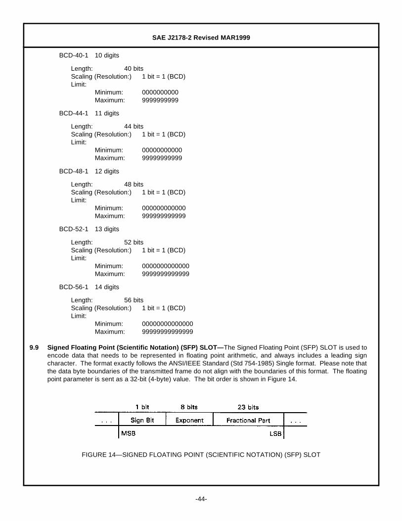
SAE J2178-2 Revised MAR1999
-44-
BCD-40-1 10 digits
Length: 40 bitsScaling (Resolution:) 1 bit = 1 (BCD)Limit:
Minimum: 0000000000Maximum: 9999999999
BCD-44-1 11 digits
Length: 44 bitsScaling (Resolution:) 1 bit = 1 (BCD)Limit:
Minimum: 00000000000Maximum: 99999999999
BCD-48-1 12 digits
Length: 48 bitsScaling (Resolution:) 1 bit = 1 (BCD)Limit:
Minimum: 000000000000Maximum: 999999999999
BCD-52-1 13 digits
Length: 52 bitsScaling (Resolution:) 1 bit = 1 (BCD)Limit:
Minimum: 0000000000000Maximum: 9999999999999
BCD-56-1 14 digits
Length: 56 bitsScaling (Resolution:) 1 bit = 1 (BCD)Limit:
Minimum: 00000000000000Maximum: 99999999999999
9.9 Signed Floating Point (Scientific Notation) (SFP) SLOT— The Signed Floating Point (SFP) SLOT is used toencode data that needs to be represented in floating point arithmetic, and always includes a leading signcharacter. The format exactly follows the ANSI/IEEE Standard (Std 754-1985) Single format. Please note thatthe data byte boundaries of the transmitted frame do not align with the boundaries of this format. The floatingpoint parameter is sent as a 32-bit (4-byte) value. The bit order is shown in Figure 14.
FIGURE 14— SIGNED FLOATING POINT (SCIENTIFIC NOTATION) (SFP) SLOT

SAE J2178-2 Revised MAR1999
-45-
9.9.1 SIGNED FLOATING POINT VARIABLE ASSIGNMENT
SFP-32-1 Floating Point
10. Multiple Frame, Single Parameter Format— This section defines the method of encoding long parametersthat require more than one frame to complete. The first data byte for this format is a sequence number asshown in Figure 15. The sequence byte consists of an upper nibble that identifies this frame by number in thesequence. The lower nibble is the total number of frames that make up this grouping. The sequence byte isfollowed by up to the maximum number of data bytes allowed by SAE J1850, for each frame. The entireparameter is thus built up from the total number of frames shown in the sequence tracking byte, in the ordercarried in that byte. The data field format will thus have an order indicated by Figure 16.
FIGURE 15— SEQUENCE TRACKING BYTE
FIGURE 16— MULTIPLE FRAME, SINGLE PARAMETER FIELD
A simple example of this format is shown in Figures 17, 18, and 19, sending an ASCII string of characters.
FIGURE 17— FIRST SEQUENCE FRAME
FIGURE 18— SECOND SEQUENCE FRAME
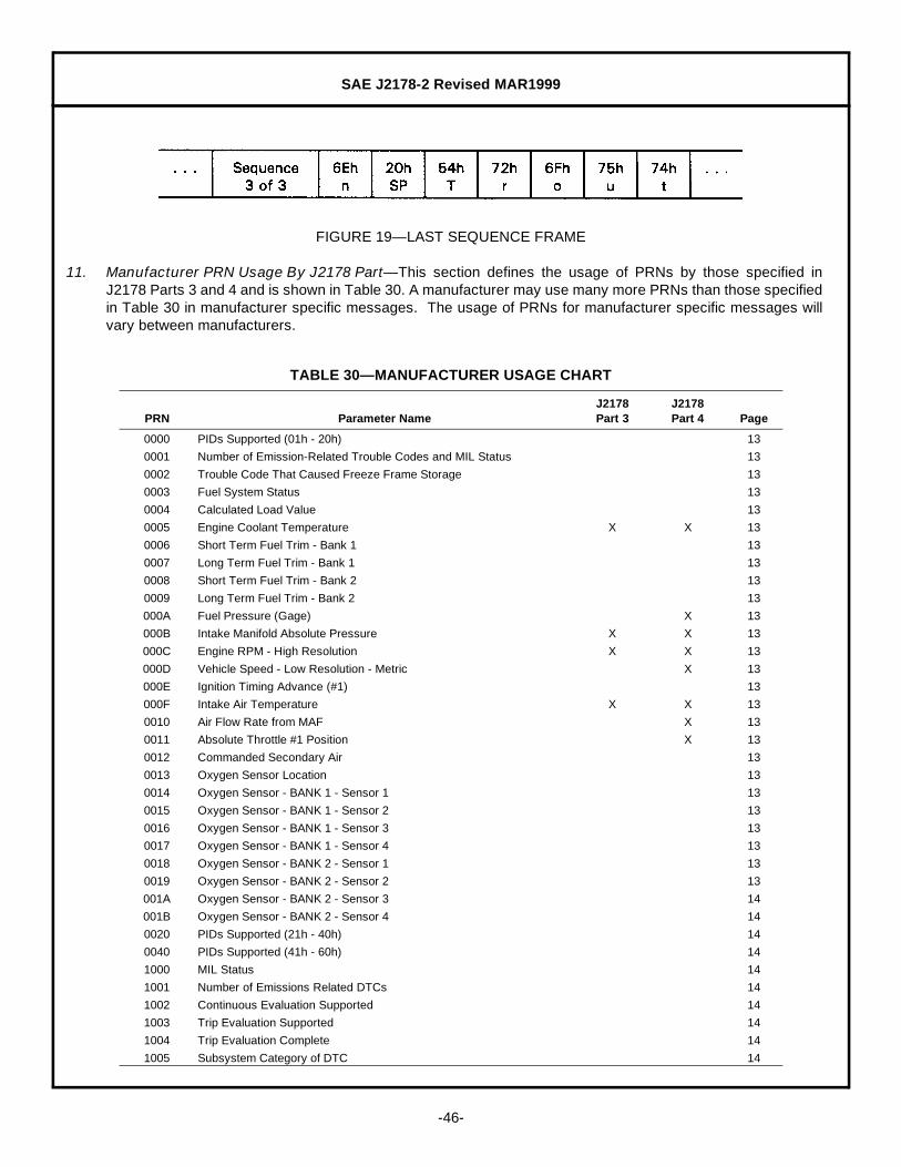
SAE J2178-2 Revised MAR1999
-46-
FIGURE 19— LAST SEQUENCE FRAME
11. Manufacturer PRN Usage By J2178 Part— This section defines the usage of PRNs by those specified inJ2178 Parts 3 and 4 and is shown in Table 30. A manufacturer may use many more PRNs than those specifiedin Table 30 in manufacturer specific messages. The usage of PRNs for manufacturer specific messages willvary between manufacturers.
TABLE 30— MANUFACTURER USAGE CHART
PRN Parameter NameJ2178Part 3
J2178Part 4 Page
0000 PIDs Supported (01h - 20h) 13
0001 Number of Emission-Related Trouble Codes and MIL Status 13
0002 Trouble Code That Caused Freeze Frame Storage 13
0003 Fuel System Status 13
0004 Calculated Load Value 13
0005 Engine Coolant Temperature X X 13
0006 Short Term Fuel Trim - Bank 1 13
0007 Long Term Fuel Trim - Bank 1 13
0008 Short Term Fuel Trim - Bank 2 13
0009 Long Term Fuel Trim - Bank 2 13
000A Fuel Pressure (Gage) X 13
000B Intake Manifold Absolute Pressure X X 13
000C Engine RPM - High Resolution X X 13
000D Vehicle Speed - Low Resolution - Metric X 13
000E Ignition Timing Advance (#1) 13
000F Intake Air Temperature X X 13
0010 Air Flow Rate from MAF X 13
0011 Absolute Throttle #1 Position X 13
0012 Commanded Secondary Air 13
0013 Oxygen Sensor Location 13
0014 Oxygen Sensor - BANK 1 - Sensor 1 13
0015 Oxygen Sensor - BANK 1 - Sensor 2 13
0016 Oxygen Sensor - BANK 1 - Sensor 3 13
0017 Oxygen Sensor - BANK 1 - Sensor 4 13
0018 Oxygen Sensor - BANK 2 - Sensor 1 13
0019 Oxygen Sensor - BANK 2 - Sensor 2 13
001A Oxygen Sensor - BANK 2 - Sensor 3 14
001B Oxygen Sensor - BANK 2 - Sensor 4 14
0020 PIDs Supported (21h - 40h) 14
0040 PIDs Supported (41h - 60h) 14
1000 MIL Status 14
1001 Number of Emissions Related DTCs 14
1002 Continuous Evaluation Supported 14
1003 Trip Evaluation Supported 14
1004 Trip Evaluation Complete 14
1005 Subsystem Category of DTC 14
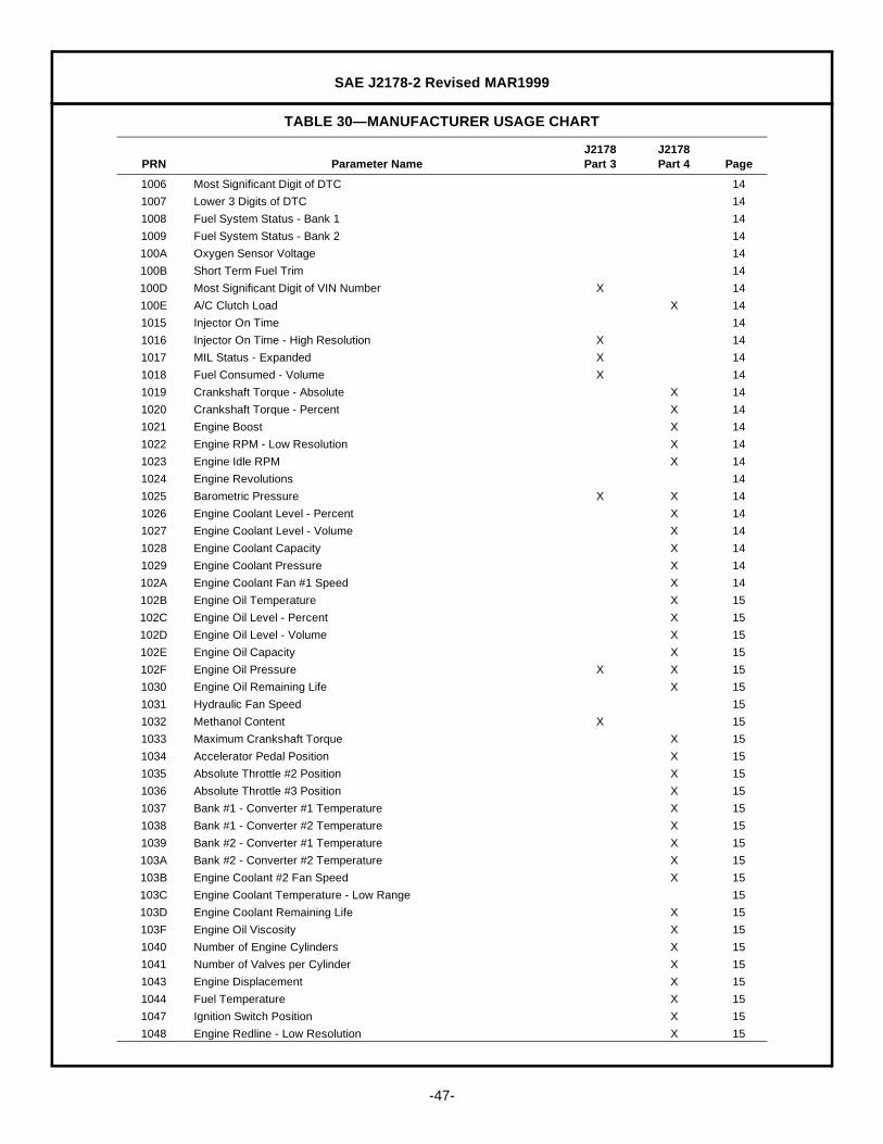
SAE J2178-2 Revised MAR1999
-47-
1006 Most Significant Digit of DTC 14
1007 Lower 3 Digits of DTC 14
1008 Fuel System Status - Bank 1 14
1009 Fuel System Status - Bank 2 14
100A Oxygen Sensor Voltage 14
100B Short Term Fuel Trim 14
100D Most Significant Digit of VIN Number X 14
100E A/C Clutch Load X 14
1015 Injector On Time 14
1016 Injector On Time - High Resolution X 14
1017 MIL Status - Expanded X 14
1018 Fuel Consumed - Volume X 14
1019 Crankshaft Torque - Absolute X 14
1020 Crankshaft Torque - Percent X 14
1021 Engine Boost X 14
1022 Engine RPM - Low Resolution X 14
1023 Engine Idle RPM X 14
1024 Engine Revolutions 14
1025 Barometric Pressure X X 14
1026 Engine Coolant Level - Percent X 14
1027 Engine Coolant Level - Volume X 14
1028 Engine Coolant Capacity X 14
1029 Engine Coolant Pressure X 14
102A Engine Coolant Fan #1 Speed X 14
102B Engine Oil Temperature X 15
102C Engine Oil Level - Percent X 15
102D Engine Oil Level - Volume X 15
102E Engine Oil Capacity X 15
102F Engine Oil Pressure X X 15
1030 Engine Oil Remaining Life X 15
1031 Hydraulic Fan Speed 15
1032 Methanol Content X 15
1033 Maximum Crankshaft Torque X 15
1034 Accelerator Pedal Position X 15
1035 Absolute Throttle #2 Position X 15
1036 Absolute Throttle #3 Position X 15
1037 Bank #1 - Converter #1 Temperature X 15
1038 Bank #1 - Converter #2 Temperature X 15
1039 Bank #2 - Converter #1 Temperature X 15
103A Bank #2 - Converter #2 Temperature X 15
103B Engine Coolant #2 Fan Speed X 15
103C Engine Coolant Temperature - Low Range 15
103D Engine Coolant Remaining Life X 15
103F Engine Oil Viscosity X 15
1040 Number of Engine Cylinders X 15
1041 Number of Valves per Cylinder X 15
1043 Engine Displacement X 15
1044 Fuel Temperature X 15
1047 Ignition Switch Position X 15
1048 Engine Redline - Low Resolution X 15
TABLE 30— MANUFACTURER USAGE CHART
PRN Parameter NameJ2178Part 3
J2178Part 4 Page

SAE J2178-2 Revised MAR1999
-48-
1049 Engine Redline - High Resolution X 15
1801 Transmission Fluid Level - Percent X 16
1802 Transmission Fluid Level - Volume X 16
1803 Transmission Fluid Capacity X 16
1804 Transmission Oil Life X 16
1805 Transmission Gear and Lockup Status 16
1806 Transmission Range Actual (PRNDL) X 16
1807 Transmission Lockup Status 16
1808 Transmission Actual Gear 16
1809 Transmission Range Selected (PRNDL) X X 16
180A Transmission Transfer Case (4WD) X 16
180B Transmission Fluid Temperature X X 16
180C Transmission Fluid Pressure X 16
180D Transmission Commanded Gear X 16
180E Transmission Actual Gear X 16
180F Transmission Gear and Lockup Status - Expanded X 16
1810 Transmission Actual Gear - Expanded X 16
2801 Wheel Speed - Low Resolution X 16
2802 Wheel Speed - High Resolution X 16
2809 Wheel Slip X 16
2819 Hydraulic Brake Fluid Supply Pump Pressure X 16
281A Hydraulic Brake Fluid Temperature X 16
281B Hydraulic Brake Fluid Recirculation Pump Pressure 16
2821 Wheel Rate 16
2829 Wheel Angular Velocity 16
2831 Wheel Angular Acceleration 16
2839 Wheel Load X 16
2841 Brake Fluid Level - Percent X 16
2842 Brake Fluid Level - Volume X 16
2843 Brake Fluid Remaining Life X 16
2844 Brake Fluid Capacity X 16
2849 Tire Temperature X 16
2851 Tire Pressure X 16
2859 Tire Type 16
2861 Tire Tread Wear Level X 16
3001 Steering Wheel Angle X 17
3005 Power Steering Fluid Temperature X 17
3006 Power Steering Fluid Pressure X 17
3007 Power Steering Fluid Level - Percent X 17
3008 Power Steering Fluid Level - Volume X 17
3009 Power Steering Fluid Remaining Life X 17
300B Power Steering Fluid Capacity X 17
300C Steering Wheel Rate X 17
300D Steering Wheel Torque X 17
300E Wheel Steer Angle X 17
3801 Lateral Acceleration 17
3802 Longitudinal Acceleration 17
3803 Yaw Acceleration 17
3804 Suspension Ride Setting X 17
3805 Suspension Fluid Temperature X 17
TABLE 30— MANUFACTURER USAGE CHART
PRN Parameter NameJ2178Part 3
J2178Part 4 Page

SAE J2178-2 Revised MAR1999
-49-
3806 Suspension Fluid Pressure X 17
3807 Suspension Fluid Level - Percent X 17
3808 Suspension Fluid Level - Volume X 17
3809 Suspension Fluid Remaining Life X 17
380A Suspension Fluid Capacity X 17
380B Vehicle Lateral Velocity 17
380C Vehicle Longitudinal Velocity 17
380D Vehicle Yaw Velocity 17
5801 Shoulder Belt Position X 17
6001 Vehicle Speed - High Resolution - Metric X X 18
6002 Vehicle Speed - High Resolution - English 18
6003 Compass Direction 18
6004 Odometer - Vehicle - Metric X 18
6005 Fuel Level - Percent X X 18
6006 Fuel Level - Volume X 18
6007 Fuel Capacity X 18
600A Battery Voltage - Low Resolution X X 18
600B Battery Temperature X X 18
600C Electrical Energy Load 18
600D Date (Dw8:DD:MM:YY) X 18
600E Year (YY) X 18
600F Year (Yr) 18
6010 Month (Mn) 18
6011 Month (MM) X 18
6012 Day of Week (Dw4) 18
6013 Day of Week (Dw8) X 18
6014 Day of Month (Dm) 18
6015 Day of Month (DD) X 18
6016 Time of Day (HH:MM:SS) X 18
6017 Hours (HH) X 18
6018 Minutes (MM) X 18
6019 Seconds (SS) X 18
601A Battery Voltage - High Resolution 18
601B Distance Traveled - English X 18
601C Fuel Used - Metric 18
601D Distance To Empty - English X 18
601E Vehicle Speed - Low Resolution - English 18
601F Hours (Hr) - 0 - 23 numeric 18
6020 Average Fuel Economy - Low Resolution - Metric X 18
6021 Average Fuel Economy - Low Resolution - English 18
6022 Elapsed Time - Seconds 18
6023 Date (Dw4\Mn:Dm) 18
6024 Elapsed Time - Minutes 18
6025 Accumulated Ignition On Time X 18
6026 Fuel Used - English 18
6027 Distance To Empty - Metric 18
6028 Average Fuel Economy - High Resolution - Metric 18
6029 Average Fuel Economy - High Resolution - English X 18
602A Elapsed Time - Hours 18
602B Display Brightness X X 18
TABLE 30— MANUFACTURER USAGE CHART
PRN Parameter NameJ2178Part 3
J2178Part 4 Page
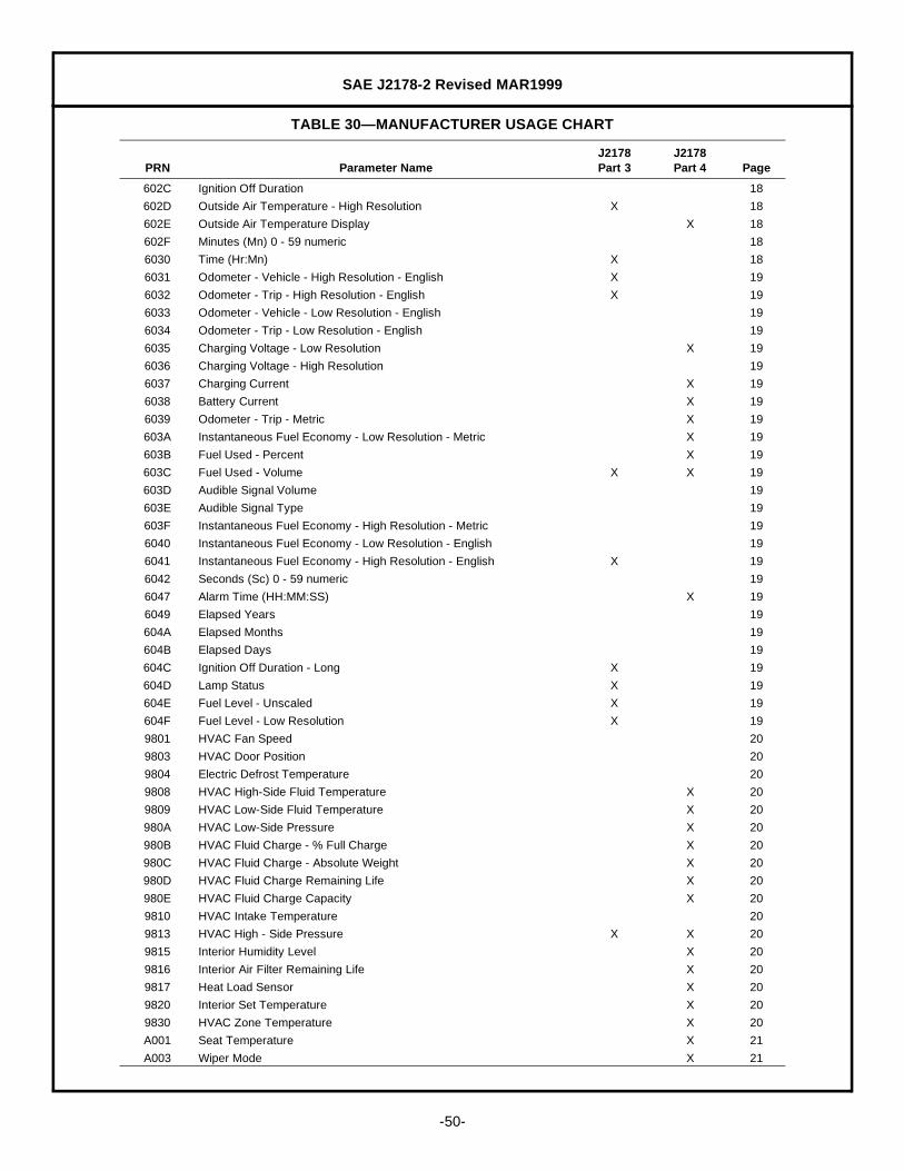
SAE J2178-2 Revised MAR1999
-50-
602C Ignition Off Duration 18
602D Outside Air Temperature - High Resolution X 18
602E Outside Air Temperature Display X 18
602F Minutes (Mn) 0 - 59 numeric 18
6030 Time (Hr:Mn) X 18
6031 Odometer - Vehicle - High Resolution - English X 19
6032 Odometer - Trip - High Resolution - English X 19
6033 Odometer - Vehicle - Low Resolution - English 19
6034 Odometer - Trip - Low Resolution - English 19
6035 Charging Voltage - Low Resolution X 19
6036 Charging Voltage - High Resolution 19
6037 Charging Current X 19
6038 Battery Current X 19
6039 Odometer - Trip - Metric X 19
603A Instantaneous Fuel Economy - Low Resolution - Metric X 19
603B Fuel Used - Percent X 19
603C Fuel Used - Volume X X 19
603D Audible Signal Volume 19
603E Audible Signal Type 19
603F Instantaneous Fuel Economy - High Resolution - Metric 19
6040 Instantaneous Fuel Economy - Low Resolution - English 19
6041 Instantaneous Fuel Economy - High Resolution - English X 19
6042 Seconds (Sc) 0 - 59 numeric 19
6047 Alarm Time (HH:MM:SS) X 19
6049 Elapsed Years 19
604A Elapsed Months 19
604B Elapsed Days 19
604C Ignition Off Duration - Long X 19
604D Lamp Status X 19
604E Fuel Level - Unscaled X 19
604F Fuel Level - Low Resolution X 19
9801 HVAC Fan Speed 20
9803 HVAC Door Position 20
9804 Electric Defrost Temperature 20
9808 HVAC High-Side Fluid Temperature X 20
9809 HVAC Low-Side Fluid Temperature X 20
980A HVAC Low-Side Pressure X 20
980B HVAC Fluid Charge - % Full Charge X 20
980C HVAC Fluid Charge - Absolute Weight X 20
980D HVAC Fluid Charge Remaining Life X 20
980E HVAC Fluid Charge Capacity X 20
9810 HVAC Intake Temperature 20
9813 HVAC High - Side Pressure X X 20
9815 Interior Humidity Level X 20
9816 Interior Air Filter Remaining Life X 20
9817 Heat Load Sensor X 20
9820 Interior Set Temperature X 20
9830 HVAC Zone Temperature X 20
A001 Seat Temperature X 21
A003 Wiper Mode X 21
TABLE 30— MANUFACTURER USAGE CHART
PRN Parameter NameJ2178Part 3
J2178Part 4 Page
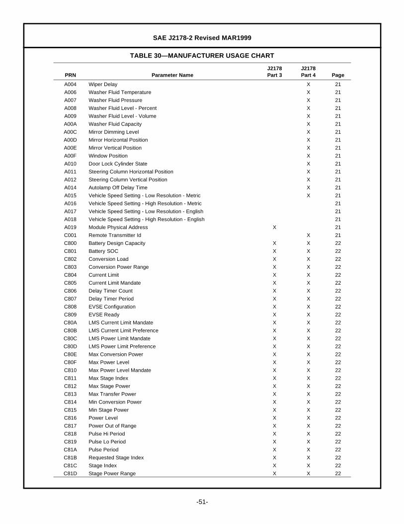
SAE J2178-2 Revised MAR1999
-51-
A004 Wiper Delay X 21
A006 Washer Fluid Temperature X 21
A007 Washer Fluid Pressure X 21
A008 Washer Fluid Level - Percent X 21
A009 Washer Fluid Level - Volume X 21
A00A Washer Fluid Capacity X 21
A00C Mirror Dimming Level X 21
A00D Mirror Horizontal Position X 21
A00E Mirror Vertical Position X 21
A00F Window Position X 21
A010 Door Lock Cylinder State X 21
A011 Steering Column Horizontal Position X 21
A012 Steering Column Vertical Position X 21
A014 Autolamp Off Delay Time X 21
A015 Vehicle Speed Setting - Low Resolution - Metric X 21
A016 Vehicle Speed Setting - High Resolution - Metric 21
A017 Vehicle Speed Setting - Low Resolution - English 21
A018 Vehicle Speed Setting - High Resolution - English 21
A019 Module Physical Address X 21
C001 Remote Transmitter Id X 21
C800 Battery Design Capacity X X 22
C801 Battery SOC X X 22
C802 Conversion Load X X 22
C803 Conversion Power Range X X 22
C804 Current Limit X X 22
C805 Current Limit Mandate X X 22
C806 Delay Timer Count X X 22
C807 Delay Timer Period X X 22
C808 EVSE Configuration X X 22
C809 EVSE Ready X X 22
C80A LMS Current Limit Mandate X X 22
C80B LMS Current Limit Preference X X 22
C80C LMS Power Limit Mandate X X 22
C80D LMS Power Limit Preference X X 22
C80E Max Conversion Power X X 22
C80F Max Power Level X X 22
C810 Max Power Level Mandate X X 22
C811 Max Stage Index X X 22
C812 Max Stage Power X X 22
C813 Max Transfer Power X X 22
C814 Min Conversion Power X X 22
C815 Min Stage Power X X 22
C816 Power Level X X 22
C817 Power Out of Range X X 22
C818 Pulse Hi Period X X 22
C819 Pulse Lo Period X X 22
C81A Pulse Period X X 22
C81B Requested Stage Index X X 22
C81C Stage Index X X 22
C81D Stage Power Range X X 22
TABLE 30— MANUFACTURER USAGE CHART
PRN Parameter NameJ2178Part 3
J2178Part 4 Page

SAE J2178-2 Revised MAR1999
-52-
12. Notes
12.1 Marginal Indicia— The change bar (l) located in the left margin is for the convenience of the user in locatingareas where technical revisions have been made to the previous issue of the report. An (R) symbol to the leftof the document title indicates a complete revision of the report.
PREPARED BY THE SAE VEHICLE NETWORK FOR MULTIPLEX ANDDATA COMMUNICATION STANDARDS COMMITTEE
C81E Transfer Type X X 22
C81F Usage Mode X X 22
C820 Usage Mode Time X X 22
C821 Vehicle Ready X X 22
C822 Voltage Level X X 22
C823 Voltage Mode Control X X 22
C824 Voltage Mode Enabled X X 22
C825 App Comm State X X 22
C826 App Service Request X X 22
C827 App Service Request Enable X X 22
C828 Comm State X X 22
C829 App ID X X 22
C82A App Type X X 22
C82B State Flag X X 22
C82C Transfer Type Preference X X 22
E021 Vehicle Id Number (VIN) #1 X 23
E022 Vehicle Id Number (VIN) #2 X X 23
E023 Vehicle Id Number (VIN) #3 X X 23
E024 Vehicle Id Number (VIN) #4 X X 23
E025 Vehicle Id Number (VIN) #5 X X 23
E026 Vehicle Id Number (VIN) #6 (reserved for future use) X 23
E027 Vehicle Id Number (VIN) #7 (reserved for future use) X 23
F801 One Byte Zero Fill 23
F802 Two Byte Zero Fill 23
F803 Three Byte Zero Fill 23
F804 Four Byte Zero Fill 23
F805 Five Byte Zero Fill 23
F806 Six Byte Zero Fill 23
F087 Seven Byte Zero Fill 23
F810 One Bit Zero Fill 23
F811 Two Bit Zero Fill 23
F812 Three Bit Zero Fill 23
F813 Four Bit Zero Fill 23
F814 Five Bit Zero Fill 23
F815 Six Bit Zero Fill 23
F816 Seven Bit Zero Fill 23
TABLE 30— MANUFACTURER USAGE CHART
PRN Parameter NameJ2178Part 3
J2178Part 4 Page

SAE J2178-2 Revised MAR1999
-53-
APPENDIX A
PARAMETER NAME CROSS REFERENCE
PRN Parameter Name .............................................................................................................................Page
100E A/C Clutch Load................................................................................................................................... 14
0011 Absolute Throttle #1 Position.............................................................................................................. 13
1035 Absolute Throttle #2 Position.............................................................................................................. 15
1036 Absolute Throttle #3 Position.............................................................................................................. 15
1034 Accelerator Pedal Position.................................................................................................................. 15
6025 Accumulated Ignition On Time............................................................................................................ 18
0010 Air Flow Rate from MAF ..................................................................................................................... 13
6047 Alarm Time (HH:MM:SS) .................................................................................................................... 19
C825 App Comm State ................................................................................................................................ 22
C829 App ID................................................................................................................................................. 22
C826 App Service Request .......................................................................................................................... 22
C827 App Service Request Enable.............................................................................................................. 22
C82A App Type ............................................................................................................................................ 22
603E Audible Signal Type............................................................................................................................ 19
603D Audible Signal Volume........................................................................................................................ 19
A014 Autolamp Off Delay Time.................................................................................................................... 21
6029 Average Fuel Economy - High Resolution - English........................................................................... 18
6028 Average Fuel Economy - High Resolution - Metric............................................................................. 18
6021 Average Fuel Economy - Low Resolution - English............................................................................ 18
6020 Average Fuel Economy - Low Resolution - Metric.............................................................................. 18
1037 Bank #1 - Converter #1 Temperature ................................................................................................. 15
1038 Bank #1 - Converter #2 Temperature ................................................................................................. 15
1039 Bank #2 - Converter #1 Temperature ................................................................................................. 15
103A Bank #2 - Converter #2 Temperature ................................................................................................. 15
1025 Barometric Pressure ........................................................................................................................... 14
6038 Battery Current ................................................................................................................................... 19
C800 Battery Design Capacity ..................................................................................................................... 22
C801 Battery SOC........................................................................................................................................ 22
600B Battery Temperature........................................................................................................................... 18
601A Battery Voltage - High Resolution....................................................................................................... 18
600A Battery Voltage - Low Resolution ....................................................................................................... 18
2844 Brake Fluid Capacity........................................................................................................................... 16
2841 Brake Fluid Level - Percent ................................................................................................................ 16
2842 Brake Fluid Level - Volume................................................................................................................. 16
2843 Brake Fluid Remaining Life................................................................................................................. 16
0004 Calculated Load Value........................................................................................................................ 13

SAE J2178-2 Revised MAR1999
-54-
6037 Charging Current ................................................................................................................................ 19
6036 Charging Voltage - High Resolution ................................................................................................... 19
6035 Charging Voltage - Low Resolution .................................................................................................... 19
C828 Comm State........................................................................................................................................ 22
0012 Commanded Secondary Air................................................................................................................ 13
6003 Compass Direction ............................................................................................................................. 18
1002 Continuous Evaluation Supported ...................................................................................................... 14
C802 Conversion Load................................................................................................................................. 22
C803 Conversion Power Range................................................................................................................... 22
1019 Crankshaft Torque - Absolute............................................................................................................. 14
1020 Crankshaft Torque - Percent .............................................................................................................. 14
C804 Current Limit ....................................................................................................................................... 22
C805 Current Limit Mandate ........................................................................................................................ 22
6023 Date (Dw4\Mn:Dm) ............................................................................................................................. 18
600D Date (Dw8:DD:MM:YY) ....................................................................................................................... 18
6015 Day of Month (DD).............................................................................................................................. 18
6014 Day of Month (Dm) ............................................................................................................................. 18
6012 Day of Week (Dw4) ............................................................................................................................. 18
6013 Day of Week (Dw8) ............................................................................................................................. 18
C806 Delay Timer Count.............................................................................................................................. 22
C807 Delay Timer Period ............................................................................................................................. 22
602B Display Brightness .............................................................................................................................. 18
601D Distance To Empty - English .............................................................................................................. 18
6027 Distance To Empty - Metric ................................................................................................................ 18
601B Distance Traveled - English................................................................................................................ 18
A010 Door Lock Cylinder State.................................................................................................................... 21
604B Elapsed Days....................................................................................................................................... 19
604A Elapsed Months .................................................................................................................................. 19
602A Elapsed Time - Hours ......................................................................................................................... 18
6024 Elapsed Time - Minutes ...................................................................................................................... 18
6022 Elapsed Time - Seconds..................................................................................................................... 18
6049 Elapsed Years .................................................................................................................................... 19
9804 Electric Defrost Temperature.............................................................................................................. 20
600C Electrical Energy Load........................................................................................................................ 18
1021 Engine Boost ...................................................................................................................................... 14
103B Engine Coolant #2 Fan Speed............................................................................................................ 15
1028 Engine Coolant Capacity .................................................................................................................... 14
102A Engine Coolant Fan #1 Speed............................................................................................................ 14
1026 Engine Coolant Level - Percent .......................................................................................................... 14
1027 Engine Coolant Level - Volume .......................................................................................................... 14
1029 Engine Coolant Pressure.................................................................................................................... 14
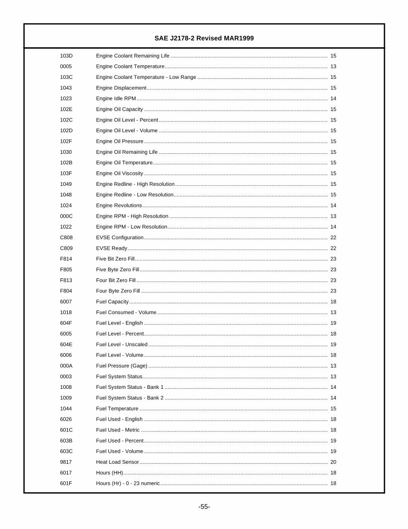
SAE J2178-2 Revised MAR1999
-55-
103D Engine Coolant Remaining Life .......................................................................................................... 15
0005 Engine Coolant Temperature.............................................................................................................. 13
103C Engine Coolant Temperature - Low Range ........................................................................................ 15
1043 Engine Displacement.......................................................................................................................... 15
1023 Engine Idle RPM................................................................................................................................. 14
102E Engine Oil Capacity ............................................................................................................................ 15
102C Engine Oil Level - Percent .................................................................................................................. 15
102D Engine Oil Level - Volume .................................................................................................................. 15
102F Engine Oil Pressure............................................................................................................................ 15
1030 Engine Oil Remaining Life .................................................................................................................. 15
102B Engine Oil Temperature...................................................................................................................... 15
103F Engine Oil Viscosity ............................................................................................................................ 15
1049 Engine Redline - High Resolution....................................................................................................... 15
1048 Engine Redline - Low Resolution........................................................................................................ 15
1024 Engine Revolutions............................................................................................................................. 14
000C Engine RPM - High Resolution ........................................................................................................... 13
1022 Engine RPM - Low Resolution............................................................................................................ 14
C808 EVSE Configuration............................................................................................................................ 22
C809 EVSE Ready....................................................................................................................................... 22
F814 Five Bit Zero Fill .................................................................................................................................. 23
F805 Five Byte Zero Fill ............................................................................................................................... 23
F813 Four Bit Zero Fill ................................................................................................................................. 23
F804 Four Byte Zero Fill .............................................................................................................................. 23
6007 Fuel Capacity...................................................................................................................................... 18
1018 Fuel Consumed - Volume ................................................................................................................... 13
604F Fuel Level - English ............................................................................................................................ 19
6005 Fuel Level - Percent............................................................................................................................ 18
604E Fuel Level - Unscaled ......................................................................................................................... 19
6006 Fuel Level - Volume............................................................................................................................ 18
000A Fuel Pressure (Gage) ......................................................................................................................... 13
0003 Fuel System Status............................................................................................................................. 13
1008 Fuel System Status - Bank 1 .............................................................................................................. 14
1009 Fuel System Status - Bank 2 .............................................................................................................. 14
1044 Fuel Temperature ............................................................................................................................... 15
6026 Fuel Used - English ............................................................................................................................ 18
601C Fuel Used - Metric .............................................................................................................................. 18
603B Fuel Used - Percent............................................................................................................................ 19
603C Fuel Used - Volume............................................................................................................................ 19
9817 Heat Load Sensor............................................................................................................................... 20
6017 Hours (HH).......................................................................................................................................... 18
601F Hours (Hr) - 0 - 23 numeric................................................................................................................. 18
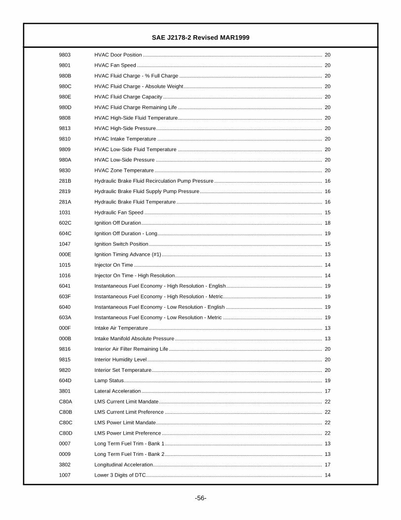
SAE J2178-2 Revised MAR1999
-56-
9803 HVAC Door Position ........................................................................................................................... 20
9801 HVAC Fan Speed ............................................................................................................................... 20
980B HVAC Fluid Charge - % Full Charge .................................................................................................. 20
980C HVAC Fluid Charge - Absolute Weight............................................................................................... 20
980E HVAC Fluid Charge Capacity ............................................................................................................. 20
980D HVAC Fluid Charge Remaining Life ................................................................................................... 20
9808 HVAC High-Side Fluid Temperature................................................................................................... 20
9813 HVAC High-Side Pressure.................................................................................................................. 20
9810 HVAC Intake Temperature ................................................................................................................. 20
9809 HVAC Low-Side Fluid Temperature ................................................................................................... 20
980A HVAC Low-Side Pressure .................................................................................................................. 20
9830 HVAC Zone Temperature ................................................................................................................... 20
281B Hydraulic Brake Fluid Recirculation Pump Pressure .......................................................................... 16
2819 Hydraulic Brake Fluid Supply Pump Pressure.................................................................................... 16
281A Hydraulic Brake Fluid Temperature .................................................................................................... 16
1031 Hydraulic Fan Speed .......................................................................................................................... 15
602C Ignition Off Duration............................................................................................................................ 18
604C Ignition Off Duration - Long................................................................................................................. 19
1047 Ignition Switch Position....................................................................................................................... 15
000E Ignition Timing Advance (#1) .............................................................................................................. 13
1015 Injector On Time ................................................................................................................................. 14
1016 Injector On Time - High Resolution..................................................................................................... 14
6041 Instantaneous Fuel Economy - High Resolution - English.................................................................. 19
603F Instantaneous Fuel Economy - High Resolution - Metric.................................................................... 19
6040 Instantaneous Fuel Economy - Low Resolution - English .................................................................. 19
603A Instantaneous Fuel Economy - Low Resolution - Metric .................................................................... 19
000F Intake Air Temperature ....................................................................................................................... 13
000B Intake Manifold Absolute Pressure ..................................................................................................... 13
9816 Interior Air Filter Remaining Life ......................................................................................................... 20
9815 Interior Humidity Level ........................................................................................................................ 20
9820 Interior Set Temperature..................................................................................................................... 20
604D Lamp Status........................................................................................................................................ 19
3801 Lateral Acceleration ............................................................................................................................ 17
C80A LMS Current Limit Mandate................................................................................................................ 22
C80B LMS Current Limit Preference ............................................................................................................ 22
C80C LMS Power Limit Mandate.................................................................................................................. 22
C80D LMS Power Limit Preference .............................................................................................................. 22
0007 Long Term Fuel Trim - Bank 1............................................................................................................ 13
0009 Long Term Fuel Trim - Bank 2............................................................................................................ 13
3802 Longitudinal Acceleration.................................................................................................................... 17
1007 Lower 3 Digits of DTC......................................................................................................................... 14
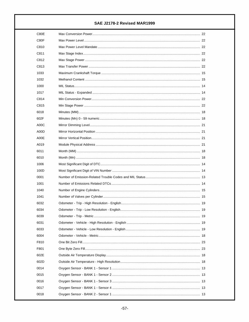
SAE J2178-2 Revised MAR1999
-57-
C80E Max Conversion Power....................................................................................................................... 22
C80F Max Power Level ................................................................................................................................ 22
C810 Max Power Level Mandate ................................................................................................................. 22
C811 Max Stage Index................................................................................................................................. 22
C812 Max Stage Power ............................................................................................................................... 22
C813 Max Transfer Power ........................................................................................................................... 22
1033 Maximum Crankshaft Torque ............................................................................................................. 15
1032 Methanol Content ............................................................................................................................... 15
1000 MIL Status........................................................................................................................................... 14
1017 MIL Status - Expanded ....................................................................................................................... 14
C814 Min Conversion Power........................................................................................................................ 22
C815 Min Stage Power ................................................................................................................................ 22
6018 Minutes (MM)...................................................................................................................................... 18
602F Minutes (Mn) 0 - 59 numeric............................................................................................................... 18
A00C Mirror Dimming Level.......................................................................................................................... 21
A00D Mirror Horizontal Position ................................................................................................................... 21
A00E Mirror Vertical Position........................................................................................................................ 21
A019 Module Physical Address ................................................................................................................... 21
6011 Month (MM) ........................................................................................................................................ 18
6010 Month (Mn) ......................................................................................................................................... 18
1006 Most Significant Digit of DTC.............................................................................................................. 14
100D Most Significant Digit of VIN Number ................................................................................................. 14
0001 Number of Emission-Related Trouble Codes and MIL Status ............................................................ 13
1001 Number of Emissions Related DTCs.................................................................................................. 14
1040 Number of Engine Cylinders............................................................................................................... 15
1041 Number of Valves per Cylinder........................................................................................................... 15
6032 Odometer - Trip - High Resolution - English....................................................................................... 19
6034 Odometer - Trip - Low Resolution - English........................................................................................ 19
6039 Odometer - Trip - Metric ..................................................................................................................... 19
6031 Odometer - Vehicle - High Resolution - English ................................................................................. 19
6033 Odometer - Vehicle - Low Resolution - English .................................................................................. 19
6004 Odometer - Vehicle - Metric................................................................................................................ 18
F810 One Bit Zero Fill .................................................................................................................................. 23
F801 One Byte Zero Fill ............................................................................................................................... 23
602E Outside Air Temperature Display........................................................................................................ 18
602D Outside Air Temperature - High Resolution........................................................................................ 18
0014 Oxygen Sensor - BANK 1 - Sensor 1 ................................................................................................. 13
0015 Oxygen Sensor - BANK 1 - Sensor 2 ................................................................................................. 13
0016 Oxygen Sensor - BANK 1 - Sensor 3 ................................................................................................. 13
0017 Oxygen Sensor - BANK 1 - Sensor 4 ................................................................................................. 13
0018 Oxygen Sensor - BANK 2 - Sensor 1 ................................................................................................. 13
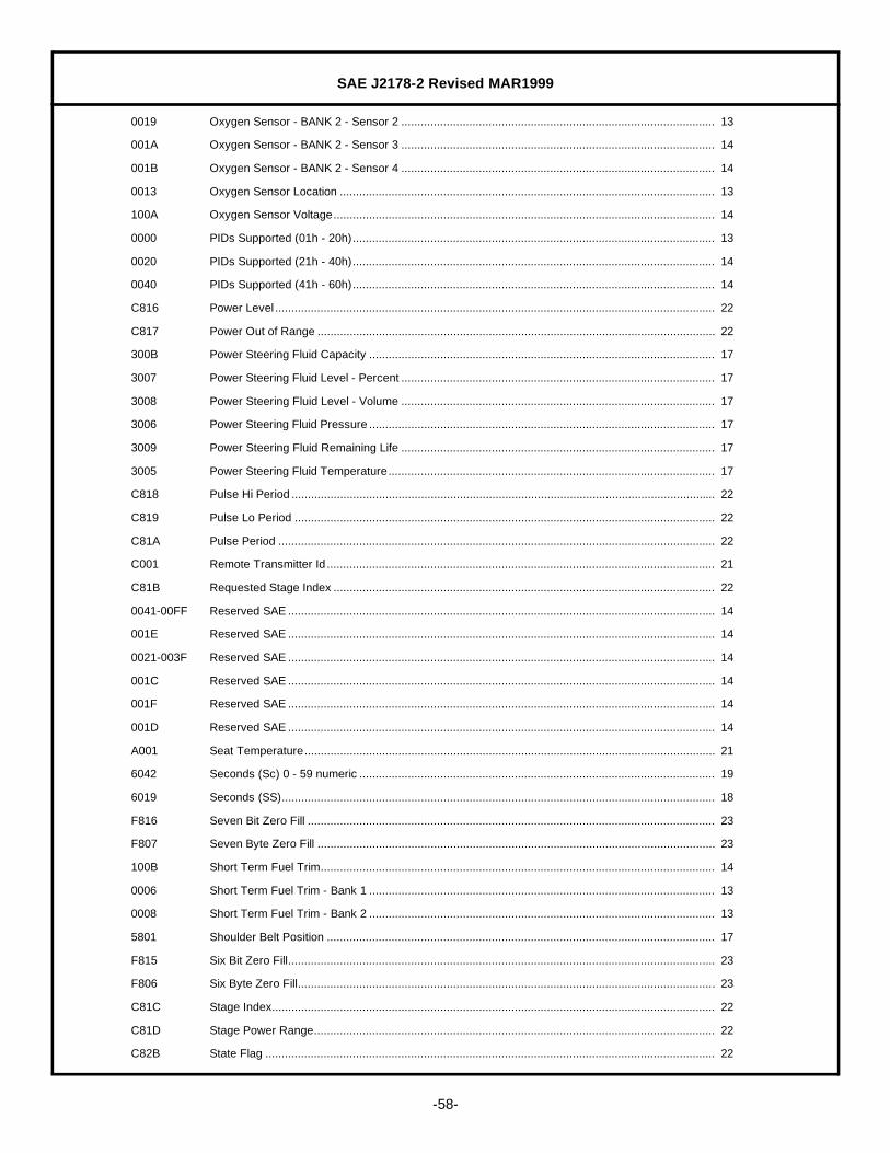
SAE J2178-2 Revised MAR1999
-58-
0019 Oxygen Sensor - BANK 2 - Sensor 2 ................................................................................................. 13
001A Oxygen Sensor - BANK 2 - Sensor 3 ................................................................................................. 14
001B Oxygen Sensor - BANK 2 - Sensor 4 ................................................................................................. 14
0013 Oxygen Sensor Location .................................................................................................................... 13
100A Oxygen Sensor Voltage...................................................................................................................... 14
0000 PIDs Supported (01h - 20h)................................................................................................................ 13
0020 PIDs Supported (21h - 40h)................................................................................................................ 14
0040 PIDs Supported (41h - 60h)................................................................................................................ 14
C816 Power Level ........................................................................................................................................ 22
C817 Power Out of Range ........................................................................................................................... 22
300B Power Steering Fluid Capacity ........................................................................................................... 17
3007 Power Steering Fluid Level - Percent ................................................................................................. 17
3008 Power Steering Fluid Level - Volume ................................................................................................. 17
3006 Power Steering Fluid Pressure ........................................................................................................... 17
3009 Power Steering Fluid Remaining Life ................................................................................................. 17
3005 Power Steering Fluid Temperature..................................................................................................... 17
C818 Pulse Hi Period ................................................................................................................................... 22
C819 Pulse Lo Period .................................................................................................................................. 22
C81A Pulse Period ....................................................................................................................................... 22
C001 Remote Transmitter Id ........................................................................................................................ 21
C81B Requested Stage Index ...................................................................................................................... 22
0041-00FF Reserved SAE .................................................................................................................................... 14
001E Reserved SAE .................................................................................................................................... 14
0021-003F Reserved SAE .................................................................................................................................... 14
001C Reserved SAE .................................................................................................................................... 14
001F Reserved SAE .................................................................................................................................... 14
001D Reserved SAE .................................................................................................................................... 14
A001 Seat Temperature............................................................................................................................... 21
6042 Seconds (Sc) 0 - 59 numeric .............................................................................................................. 19
6019 Seconds (SS)...................................................................................................................................... 18
F816 Seven Bit Zero Fill .............................................................................................................................. 23
F807 Seven Byte Zero Fill ........................................................................................................................... 23
100B Short Term Fuel Trim.......................................................................................................................... 14
0006 Short Term Fuel Trim - Bank 1 ........................................................................................................... 13
0008 Short Term Fuel Trim - Bank 2 ........................................................................................................... 13
5801 Shoulder Belt Position ........................................................................................................................ 17
F815 Six Bit Zero Fill.................................................................................................................................... 23
F806 Six Byte Zero Fill................................................................................................................................. 23
C81C Stage Index......................................................................................................................................... 22
C81D Stage Power Range............................................................................................................................ 22
C82B State Flag ........................................................................................................................................... 22
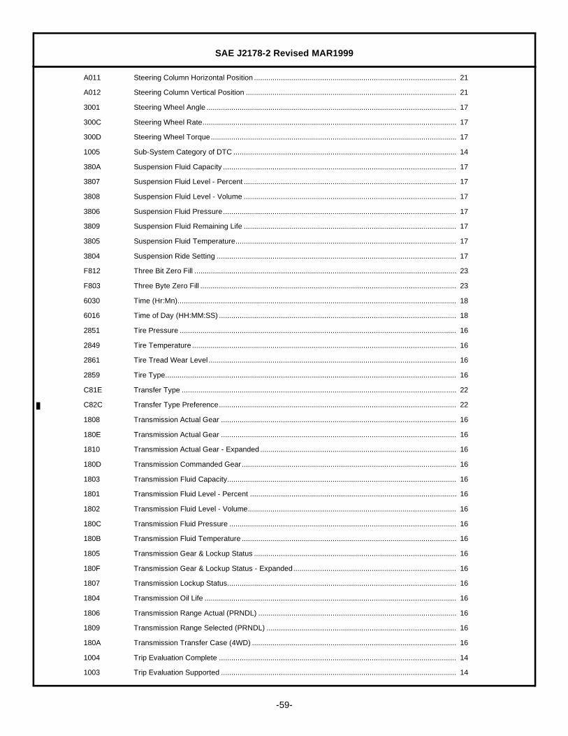
SAE J2178-2 Revised MAR1999
-59-
A011 Steering Column Horizontal Position .................................................................................................. 21
A012 Steering Column Vertical Position ...................................................................................................... 21
3001 Steering Wheel Angle ......................................................................................................................... 17
300C Steering Wheel Rate........................................................................................................................... 17
300D Steering Wheel Torque....................................................................................................................... 17
1005 Sub-System Category of DTC ............................................................................................................ 14
380A Suspension Fluid Capacity ................................................................................................................. 17
3807 Suspension Fluid Level - Percent ....................................................................................................... 17
3808 Suspension Fluid Level - Volume ....................................................................................................... 17
3806 Suspension Fluid Pressure................................................................................................................. 17
3809 Suspension Fluid Remaining Life ....................................................................................................... 17
3805 Suspension Fluid Temperature........................................................................................................... 17
3804 Suspension Ride Setting .................................................................................................................... 17
F812 Three Bit Zero Fill ............................................................................................................................... 23
F803 Three Byte Zero Fill ............................................................................................................................ 23
6030 Time (Hr:Mn)....................................................................................................................................... 18
6016 Time of Day (HH:MM:SS) ................................................................................................................... 18
2851 Tire Pressure ...................................................................................................................................... 16
2849 Tire Temperature ................................................................................................................................ 16
2861 Tire Tread Wear Level ........................................................................................................................ 16
2859 Tire Type............................................................................................................................................. 16
C81E Transfer Type ..................................................................................................................................... 22
C82C Transfer Type Preference................................................................................................................... 22
1808 Transmission Actual Gear .................................................................................................................. 16
180E Transmission Actual Gear .................................................................................................................. 16
1810 Transmission Actual Gear - Expanded ............................................................................................... 16
180D Transmission Commanded Gear........................................................................................................ 16
1803 Transmission Fluid Capacity............................................................................................................... 16
1801 Transmission Fluid Level - Percent .................................................................................................... 16
1802 Transmission Fluid Level - Volume..................................................................................................... 16
180C Transmission Fluid Pressure .............................................................................................................. 16
180B Transmission Fluid Temperature ........................................................................................................ 16
1805 Transmission Gear & Lockup Status .................................................................................................. 16
180F Transmission Gear & Lockup Status - Expanded............................................................................... 16
1807 Transmission Lockup Status............................................................................................................... 16
1804 Transmission Oil Life .......................................................................................................................... 16
1806 Transmission Range Actual (PRNDL) ................................................................................................ 16
1809 Transmission Range Selected (PRNDL) ............................................................................................ 16
180A Transmission Transfer Case (4WD) ................................................................................................... 16
1004 Trip Evaluation Complete ................................................................................................................... 14
1003 Trip Evaluation Supported .................................................................................................................. 14
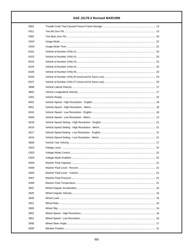
SAE J2178-2 Revised MAR1999
-60-
0002 Trouble Code That Caused Freeze Frame Storage ........................................................................... 13
F811 Two Bit Zero Fill .................................................................................................................................. 23
F802 Two Byte Zero Fill ............................................................................................................................... 23
C81F Usage Mode ....................................................................................................................................... 22
C820 Usage Mode Time .............................................................................................................................. 22
E021 Vehicle Id Number (VIN) #1................................................................................................................ 23
E022 Vehicle Id Number (VIN) #2................................................................................................................ 23
E023 Vehicle Id Number (VIN) #3................................................................................................................ 23
E024 Vehicle Id Number (VIN) #4................................................................................................................ 23
E025 Vehicle Id Number (VIN) #5................................................................................................................ 23
E026 Vehicle Id Number (VIN) #6 (reserved for future use) ........................................................................ 23
E027 Vehicle Id Number (VIN) #7 (reserved for future use) ........................................................................ 23
380B Vehicle Lateral Velocity ...................................................................................................................... 17
380C Vehicle Longitudinal Velocity .............................................................................................................. 17
C821 Vehicle Ready..................................................................................................................................... 22
6002 Vehicle Speed - High Resolution - English ......................................................................................... 18
6001 Vehicle Speed - High Resolution - Metric ........................................................................................... 18
601E Vehicle Speed - Low Resolution - English.......................................................................................... 18
000D Vehicle Speed - Low Resolution - Metric............................................................................................ 13
A018 Vehicle Speed Setting - High Resolution - English............................................................................. 21
A016 Vehicle Speed Setting - High Resolution - Metric............................................................................... 21
A017 Vehicle Speed Setting - Low Resolution - English.............................................................................. 21
A015 Vehicle Speed Setting - Low Resolution - Metric................................................................................ 21
380D Vehicle Yaw Velocity .......................................................................................................................... 17
C822 Voltage Level ...................................................................................................................................... 22
C823 Voltage Mode Control ......................................................................................................................... 22
C824 Voltage Mode Enabled ....................................................................................................................... 22
A00A Washer Fluid Capacity........................................................................................................................ 21
A008 Washer Fluid Level - Percent ............................................................................................................. 21
A009 Washer Fluid Level - Volume.............................................................................................................. 21
A007 Washer Fluid Pressure ....................................................................................................................... 21
A006 Washer Fluid Temperature ................................................................................................................. 21
2831 Wheel Angular Acceleration ............................................................................................................... 16
2829 Wheel Angular Velocity....................................................................................................................... 16
2839 Wheel Load......................................................................................................................................... 16
2821 Wheel Rate ......................................................................................................................................... 16
2809 Wheel Slip........................................................................................................................................... 16
2802 Wheel Speed - High Resolution.......................................................................................................... 16
2801 Wheel Speed - Low Resolution .......................................................................................................... 16
300E Wheel Steer Angle.............................................................................................................................. 17
A00F Window Position ................................................................................................................................. 21

SAE J2178-2 Revised MAR1999
-61-
A004 Wiper Delay ........................................................................................................................................ 21
A003 Wiper Mode ........................................................................................................................................ 21
3803 Yaw Acceleration ................................................................................................................................ 17
600F Year (Yr) ............................................................................................................................................. 18
600E Year (YY) ............................................................................................................................................ 18

SAE J2178-2 Revised MAR1999
Rationale— SAE J2178-2 was revised to include terms applicable to electric vehicles and to agree with SAEJ2293. Minor typographical errors were also corrected.
Relationship of SAE Standard to ISO Standard— Not applicable.
Application— This SAE Recommended Practice defines the information contained in the header and datafields of non-diagnostic messages for automotive serial communications based on SAE J1850 Class Bnetworks. This document describes and specifies the header fields, data fields, field sizes, scaling,representations, and data positions used within messages.
Reference Section
SAE J1213-1— Glossary of Vehicle Networks for Multiplex and Data Communication
SAE J1850— Class B Data Communication Network Interface
SAE J1930— Electrical/Electronic Systems Diagnostic Terms, Definitions, Abbreviations, and Acronyms
SAE J1979— E/E Diagnostic Test Modes
SAE J2190— Enhanced E/E Diagnostic Test Modes
ANSI/IEEE Std 754-1985 August 12, 1985— IEEE Standard for Binary Floating-Point Arithmetic
Developed by the SAE Vehicle Network for Multiplex and Data Communication Standards Committee