Embed Size (px)
Citation preview

Reported by ACI Committee E 706
J. Christopher Ball H. Peter Golter Jay H. Paul
Floyd E. Dimmick, Sr. Bob Joyce George I. Taylor
Peter H. Emmons§ Kenneth M. Lozen Patrick M. Watson‡
Timothy R. W. Gillespie John S. Lund David W. Whitmore
Richard Montani†
RAP-5
Surface RepairUsing Form-and-Pump Techniques
Brian F. Keane*
Chairman
*Primary author of RAP Bulletin No. 1.†Primary author of RAP Bulletin No. 2.‡Primary author of RAP Bulletin No. 3.§Primary author of RAP Bulletin Nos. 4 and 5.
The committee would like to thank Brandon Emmons for his illustrations in these bulletins.
ACI Repair Application Procedure 5.Copyright © 2003, American Concrete Institute.All rights reserved including rights of reproduction and use in any
form or by any means, including the making of copies by any photo pro-cess, or by electronic or mechanical device, printed, written, or oral, orrecording for sound or visual reproduction or for use in any knowledgeretrieval system or device, unless permission in writing is obtained fromthe copyright proprietors. Printed in the United States of America.
The Institute is not responsible for the statements oropinions in its publications. Institute publications arenot able nor intended to supplant individual training,responsibility or judgment of the user, or the supplier ofthe information provided.
Structural DisclaimerThis document is intended as a voluntary field guide forthe Owner, design professional, and concrete repair con-tractor. It is not intended to relieve the user of this guideof responsibility for a proper condition assessment andstructural evaluation of existing conditions, and for thespecification of concrete repair methods, materials, orpractices by an experienced engineer/designer.
It is the responsibility of the user of this document toestablish health and safety practices appropriate to the specificcircumstances involved with its use. ACI does not make anyrepresentations with regard to health and safety issues and the useof this document. The user must determine the applicability ofall regulatory limitations before applying the document andmust comply with all applicable laws and regulations,including but not limited to, United States OccupationalSafety and Health Administration (OSHA) health andsafety standards.
www.concrete.org

Surface Repair Using Form-and-Pump Techniques (ACI RAP-5) 1
FIELD GUIDE TOCONCRETE REPAIR
APPLICATION PROCEDURES
Surface RepairUsing Form-and-Pump Techniques
ACI RAP Bulletin 5
by Peter Emmons

2 Repair Application Procedures Bulletin 5
Fig. 1—Lapping of supplemental reinforcing.
IntroductionThe form-and-pump repair technique is a multi-step pro-
cess of preparing and constructing formwork, and pumpingrepair material into the cavity confined by formwork andexisting concrete. The form-and-pump technique allows theuse of many different repair materials. The necessary require-ment for material selection is pumpability. Various pumpsare used, depending on the mixture design with focus onaggregate size. Prior to construction of formwork, any surfacesthat may cause air to become trapped during the pumpingprocess must be trimmed, or vent tubes installed.
Repair materials are mixed and pumped into the confinedcavity. The sequence of pumping is from low points to highpoints and when performed overhead, from one extremity tothe other. Large areas may require bulkheading to separateplacements into manageable areas. When the cavity is full,pump pressure is exerted on the form, causing the repair ma-terial to consolidate and make intimate contact, and effectbonding with existing concrete surfaces. The form-and-pumptechnique offers many advantages to alternative techniques,such as shotcrete, hand placement, and preplaced aggregate.
Advantages include:• Placement is not limited by thickness of repair or by
size or density of exposed reinforcement;• Repair materials are premixed and placed to pro-
vide a uniform cross section without segregation orintermediate bond lines;
• Sagging or dropouts of freshly placed materialsaren’t problems; all materials are supported by form-work during the placement and curing process;
• The pressurization process consolidates the repairmaterial, providing for full encapsulation of exposedreinforcing steel;
• The formwork protects the repair material duringthe curing process;
• The process is less subject to individual operatorerror; and
• Quality assurance of the in-place repair is easier toprovide.
What is the purpose of this repair?The primary purpose for this type of repair is to restore the
structural integrity, concrete cover requirements, or both, forthe damaged element.
When do I use this technique?This technique is commonly used on vertical surfaces such
as walls, columns, and other combinations such as beam sidesand bottoms. Separate bonding agents such as grouts orepoxy are not commonly used with this technique. It is highlyrecommended that for each project, a trial installation beperformed to verify the preparation, material, and placementtechnique using quality-control procedures outlined at the endof this document.
How do I prepare the surface?Regardless of the repair method, surface preparation is
essentially the same. Concrete is removed until good qualityconcrete is located. Exposed bars are undercut, and surfacesare cleaned with high-pressure water or are abrasively blasted.
With form-and-pump techniques, it is important to understandhow the existing surfaces will permit the repair material topenetrate and flow. Surfaces that might trap air need to betrimmed, or vent pipes may be provided in the formwork.Profile roughness from hand-chipping or hydrodemolition isnot generally a problem for entrapping air. Flow of the repairmaterial (while flowing within the formed cavity) will mostlikely remove air from the profile.
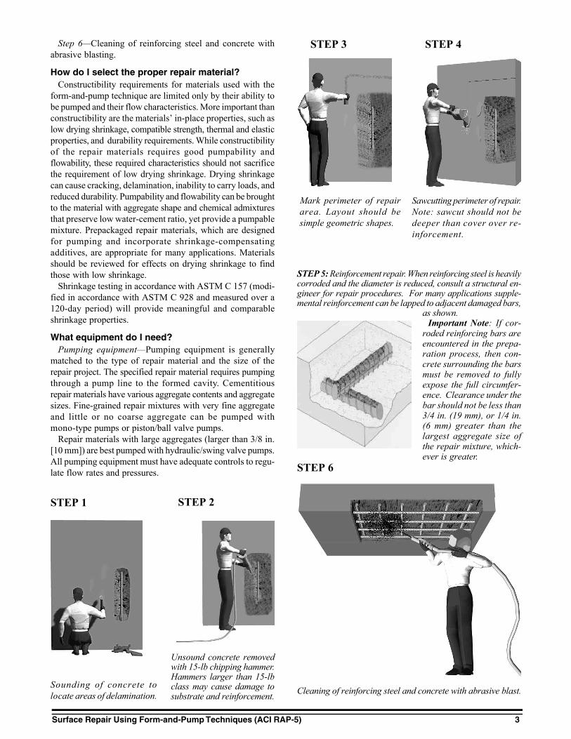
Steps in surface preparation include the following:Step 1—Sounding or other appropriate nondestructive con-
crete testing to locate areas of delamination.Step 2—Marking of the perimeter of the repair area. Lay-
out should be simple square or rectangular shapes. Thereshould be no acute angles between boundary lines definingthe repair area.
Step 3—Removal of concrete with a 15-lb chipping ham-mer. Hammers larger than a 15-lb class may cause damageto substrate and reinforcement.
Step 4—Sawcutting perimeter of the repair. Note: sawcutshould not be deeper than the cover over the reinforcement.
Step 5—Reinforcement repair. When reinforcing steel isheavily corroded and the diameter is reduced, consult a struc-tural engineer for repair procedures. For many applications,supplemental reinforcement can be lapped to adjacent damagedbars, as shown (see Fig. 1).
Surface Repair Using Form-and-Pump Techniques (ACI RAP-5) 3
Cleaning of reinforcing steel and concrete with abrasive blast.
Sawcutting perimeter of repair.Note: sawcut should not bedeeper than cover over re-inforcement.
Unsound concrete removedwith 15-lb chipping hammer.Hammers larger than 15-lbclass may cause damage tosubstrate and reinforcement.
Sounding of concrete tolocate areas of delamination.
Mark perimeter of repairarea. Layout should besimple geometric shapes.
STEP 4
STEP 2
STEP 6
STEP 5: Reinforcement repair. When reinforcing steel is heavilycorroded and the diameter is reduced, consult a structural en-gineer for repair procedures. For many applications supple-mental reinforcement can be lapped to adjacent damaged bars,
as shown.Important Note: If cor-
roded reinforcing bars areencountered in the prepa-ration process, then con-crete surrounding the barsmust be removed to fullyexpose the full circumfer-ence. Clearance under thebar should not be less than3/4 in. (19 mm), or 1/4 in.(6 mm) greater than thelargest aggregate size ofthe repair mixture, which-ever is greater.
STEP 1
STEP 3Step 6—Cleaning of reinforcing steel and concrete withabrasive blasting.
How do I select the proper repair material?Constructibility requirements for materials used with the
form-and-pump technique are limited only by their ability tobe pumped and their flow characteristics. More important thanconstructibility are the materials’ in-place properties, such aslow drying shrinkage, compatible strength, thermal and elasticproperties, and durability requirements. While constructibilityof the repair materials requires good pumpability andflowability, these required characteristics should not sacrificethe requirement of low drying shrinkage. Drying shrinkagecan cause cracking, delamination, inability to carry loads, andreduced durability. Pumpability and flowability can be broughtto the material with aggregate shape and chemical admixturesthat preserve low water-cement ratio, yet provide a pumpablemixture. Prepackaged repair materials, which are designedfor pumping and incorporate shrinkage-compensatingadditives, are appropriate for many applications. Materialsshould be reviewed for effects on drying shrinkage to findthose with low shrinkage.
Shrinkage testing in accordance with ASTM C 157 (modi-fied in accordance with ASTM C 928 and measured over a120-day period) will provide meaningful and comparableshrinkage properties.
What equipment do I need?Pumping equipment—Pumping equipment is generally
matched to the type of repair material and the size of therepair project. The specified repair material requires pumpingthrough a pump line to the formed cavity. Cementitiousrepair materials have various aggregate contents and aggregatesizes. Fine-grained repair mixtures with very fine aggregateand little or no coarse aggregate can be pumped withmono-type pumps or piston/ball valve pumps.
Repair materials with large aggregates (larger than 3/8 in.[10 mm]) are best pumped with hydraulic/swing valve pumps.All pumping equipment must have adequate controls to regu-late flow rates and pressures.

4 Repair Application Procedures Bulletin 5
Fig. 4—Immediately after stripping of formwork, curingcompound is either rolled or spray-applied.
Pumpline hooked to form and pumping of repair materialbegins
Formwork complete ready for pumpline hookup
Erection of formwork with embedded anchors supportingformwork
Fig. 2.
Pumping underway. Note flow path radiating from pumpline port.
Cavity is filled and pressurized. Pump line is shut down.
Fig. 3.
What are the safety considerations?Job site safety practices include, but are not limited to, the
following where applicable:• Material Safety Data Sheets (MSDS) available;• Protective clothing worn by workers handling or
exposed to hazardous materials;• Use of protective eyewear during pumping and
preparation;• Availability of eye wash facilities; and• Use of respirators during preparation.
Surface Repair Using Form-and-Pump Techniques (ACI RAP-5) 5
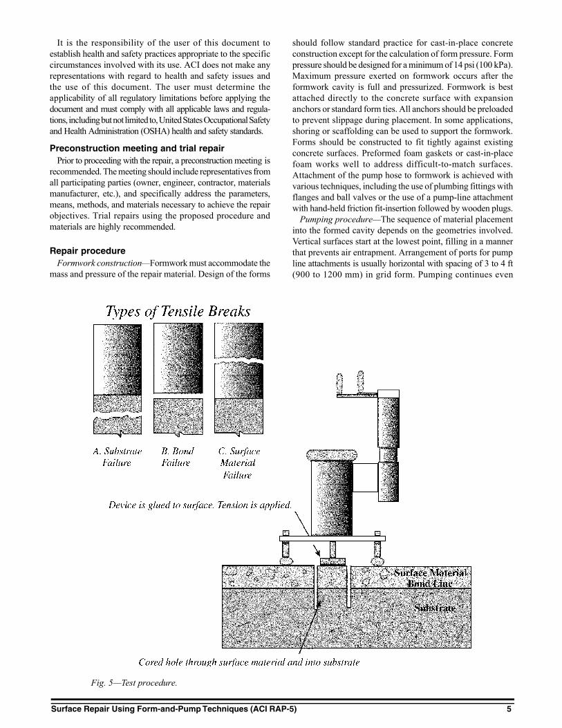
Fig. 5—Test procedure.
It is the responsibility of the user of this document toestablish health and safety practices appropriate to the specificcircumstances involved with its use. ACI does not make anyrepresentations with regard to health and safety issues andthe use of this document. The user must determine theapplicability of all regulatory limitations before applying thedocument and must comply with all applicable laws and regula-tions, including but not limited to, United States Occupational Safetyand Health Administration (OSHA) health and safety standards.
Preconstruction meeting and trial repairPrior to proceeding with the repair, a preconstruction meeting is
recommended. The meeting should include representatives fromall participating parties (owner, engineer, contractor, materialsmanufacturer, etc.), and specifically address the parameters,means, methods, and materials necessary to achieve the repairobjectives. Trial repairs using the proposed procedure andmaterials are highly recommended.
should follow standard practice for cast-in-place concreteconstruction except for the calculation of form pressure. Formpressure should be designed for a minimum of 14 psi (100 kPa).Maximum pressure exerted on formwork occurs after theformwork cavity is full and pressurized. Formwork is bestattached directly to the concrete surface with expansionanchors or standard form ties. All anchors should be preloadedto prevent slippage during placement. In some applications,shoring or scaffolding can be used to support the formwork.Forms should be constructed to fit tightly against existingconcrete surfaces. Preformed foam gaskets or cast-in-placefoam works well to address difficult-to-match surfaces.Attachment of the pump hose to formwork is achieved withvarious techniques, including the use of plumbing fittings withflanges and ball valves or the use of a pump-line attachmentwith hand-held friction fit-insertion followed by wooden plugs.
Pumping procedure—The sequence of material placementinto the formed cavity depends on the geometries involved.Vertical surfaces start at the lowest point, filling in a mannerthat prevents air entrapment. Arrangement of ports for pumpline attachments is usually horizontal with spacing of 3 to 4 ft(900 to 1200 mm) in grid form. Pumping continues even
Repair procedureFormwork construction—Formwork must accommodate the
mass and pressure of the repair material. Design of the forms

6 Repair Application Procedures Bulletin 5
Effects of not filling the cavity.
after material flow occurs from adjacent ports to expel air.When the flow is without intrusion of air, the pump is tempo-rarily shut off, the port closed off, and the pump line con-nected to the adjacent port that has seen flow. The sequenceis continued until the cavity is filled. In some conditions, thecavity can be pumped from one port. In this situation, eachadjacent port is capped off as flow occurs. It is necessary tomonitor pump-line pressure to prevent excessive backpressurewhen pumping long distances. Once the cavity is filled, thefull-line pressure is available to pressurize the formed cavity.
Care must be exercised in the final pressurization because theexcessive pump-line pressure (hydraulic pumps can exert inexcess of 800 psi [5 MPa]) may cause the form to fail. In mostapplications, pressure gages should be attached to the pumpline near the exit port to monitor cavity pressure. If the form-work fails due to overpressurization, the failure will generallyoccur as a slight movement in a form panel seam or perimeterseal. The failure is not explosive because there is no significantstored energy. Overhead placements are accomplished bystarting at an extremity of the surface and proceeding in afashion similar to vertical placements. Material will flow
radially from the injection port to adjacent ports. Repairsinvolving soffit and vertical faces of members can be combinedinto one placement. In this case, placement begins at thelowest elevation and follows the procedure detailed abovefor each orientation. Large areas of repair should besectionalized utilizing bulkheads. Bulkheads can be constructedof repair material and left in place. Utilizing bulkheads andmanageable placement volumes limits the risk of problemsassociated with large placements and allows pressurization tooccur within shorter durations of material mixing.
How do I check the repairs?After stripping of forms various tests can be performed
to confirm the placement of repair material has achievedcomplete consolidation and intimate contact with the sub-strate to achieve bond. A uniaxial bond test can be performedby drilling through the repair into the substrate. A bondedplate attached to the core is pulled until rupture occurs. Bondvalues should exceed 100 psi (0.7 MPa), and in most casesexceed 150 psi (1 MPa). These tests are performed in accor-dance with ACI 503R Appendix (see Fig. 5).
The complete repair area should also be hammer-soundedor evaluated by other non-destructive methods to determineoverall integrity. Any hollow sounds may represent poor bondor voids.
Sources for additional information1. “Guide for Surface Preparation for the Repair of Deteriorated Concrete
Resulting from Reinforced Steel Corrosion,” No. 03730, International Con-crete Repair Institute.
2. “Guide for Selecting and Specifying Concrete Repair Materials,”No. 03733, International Concrete Repair Institute.
3. ACI Committee 347, “Guide to Formwork for Concrete (ACI 347-01),”American Concrete Institute, Farmington Hills, Mich., 32 pp.
4. ACI Committee 546, “Concrete Repair Guide (546R-96),” AmericanConcrete Institute, Farmington Hills, Mich., 41 pp.
5. ACI Committee 503, “Use of Epoxy Compounds with Concrete (503R-93 (Reapproved 1998)),” American Concrete Institute, Farmington Hills,Mich., 1998, 28 pp.