Embed Size (px)
Citation preview

Surface Engineering of Specialty Steels J.R. Davis, Davis & Associates
SPECIALTY STEELS encompass a broad range of ferrous alloys noted for their special processing characteristics (powder metallurgy al- loys), corrosion resistance (stainless steels), wear resistance and toughness (tool steels), high strength (maraging steels), or magnetic properties (electrical steels). Each of these material groupsmwith the exception of stainless steels, which were discussed in the previous article in this Sectionmwill be reviewed below. Additional information on these materials can be found in Volumes 1 and 2 of the ASM Handbook.
Ferrous Powder Metallurgy Alloys
Powder metallurgy (P/M) in its simplest form consists of compressing metal powders in a shaped die to produce green compacts. These are then sintered, or diffusion bonded, at elevated temperatures in a furnace with a protective at- mosphere. During sintering, the constituents usu- ally do not melt, and the compacts become sub- stantially strengthened by the development of bonds between individual particles.
For a specific metal powder and sintering con- dition, increased compact density results in im- proved mechanical properties. The density of sin- tered compacts may be increased by re-pressing. When re-pressing is performed primarily to in- crease dimensional accuracy rather than density, it is termed sizing. When re-pressing is intended to change the contour of the surface in contact with the punches, it is termed coining. For exam- ple, a sintered blank could be coined so that the surface is indented with small slots or letters and numbers. The re-pressing may be followed by re-sintering, which relieves the stresses due to cold work and may further strengthen the com- pact. More detailed information on consolidation practices for ferrous P/M parts can be found in Ref 1 and 2.
By pressing and sintering only, parts are pro- duced at 80 to 93% of theoretical density. By re-pressing, with or without sintering, the materi- als may be further densified to 85 to 96% of theoretical density. High-temperature sintering will also produce parts at these high densities. The density of pressed parts is limited by the size and shape of the compact. The most common
P/M materials for structural parts are iron-copper- carbon, iron-nickel-carbon, and iron-carbon. Parts made from these materials respond to heat treatment with a defined hardenability band. Iron parts that are low in carbon and high in density can also be case hardened.
Designation of Ferrous P/M Materials Ferrous P/M materials are customarily desig-
nated by the specifications or standards to which they are made, such as those listed in Table 1. Comparable standards are published by ASTM, SAE, and MPIF (Metal Powder Industries Fed- eration).
The MPIF designations for ferrous P/M mate- rials, described in detail in Ref 3, include a prefix of one or more letters (the first of which is F to indicate an iron-base material), four numerals, and a suffix. The second letter in the prefix iden- tifies the principal alloying element (if one is specified); the percentage of the element is indi- cated by the first two digits. The third and fourth digits indicate the amount of carbon in the com- pacted and sintered part; the code designation 00 indicates less than 0.3 %, 05 indicates 0.3 to 0.6%, and 0.8 indicates 0.6 to 0.9%. The suffix is used to indicate the minimum 0.2% yield strength of as-sintered parts and the minimum ultimate ten- sile strength of heat-treated materials in units of 1000 psi (6.894 MPa). The letters HT designate heat treated.
Commercially produced iron-base powders often contain controlled amounts of alloying ele- ments other than those specified by any of the designations listed in Table 1. Manganese and molybdenum may be added to improve strength and the response to heat treatment. Sulfur may be added to enhance machinability. Additions of 0.45 to 0.80% P can improve the toughness of the part and reduce magnetic hysteresis losses. These powders are usually identified by the trade name of the producer even though the amounts of alloy additions are small enough that the designations listed in Table 1 could be applied to the powders. Commercially produced iron-base powders usu- ally contain very little carbon because carbon lowers compressibility and the amount of carbon in the finished part is readily controlled by the
amount of admixed graphite and the composition of the sintering atmosphere.
Deburring P/M Parts (Ref 4) Although cleaning and deburring generally are
considered different operations, they are often accomplished simultaneously. Therefore, much of the discussion on deburring is applicable to the subsequent section of this article on cleaning.
The inherent porosity in P/M parts demands special considerations in all secondary opera- tions. This is also true for cleaning and deburring; the relatively small size and complex shape of the parts also require special procedures and/or pre- cautions that are not required for wrought or cast parts. The P/M parts shown in Fig. 1 are typical of small, intricate parts that frequently present deburring problems.
Deburring Methods. Due to the nature of the P/M process, burrs typically form on the edges and surfaces of P/qVI parts. In many simple shapes, de- bun'mg is almost automaticmthat is, burrs are bro- ken off during handling operations. If parts are surface hardened or steam treated, subsequent de- burring may be unnecessary. However, for intricate parts such as those shown in Fig. 1, separate debur- ring operations generally are required.
The use of liquid deburring methods is not usually suitable, especially if such liquids are corrosive. Thus, acid pickling is not recom- mended, because acid may be entrapped in the pores, resulting in severe corrosion. Tumbling in a wet medium is used frequently as a deburring method, but removal of the liquid from the pores requires extra drying time. Preferred methods of deburring include:
• Rotary tumbling (self or with abrasive) • Vibratory • Abrasive blasting • Centrifugal or high-energy methods
These methods, which are used for deburring and sometimes for cleaning, are described in the articles "Mechanical Cleaning Systems" and "Mass Finishing Methods" in this Volume. The discussions that follow are unique to P/M parts.
ASM Handbook, Volume 5: Surface EngineeringC.M. Cotell, J.A. Sprague, and F.A. Smidt, Jr., editors, p 762-775DOI: 10.1361/asmhba0001306
Copyright © 1994 ASM International® All rights reserved.
www.asminternational.org

Surface Engineering of Specialty Steels / 763
Table I Compositions of ferrous P/M structural materials Designation(a)
Description MPIF ASTM SAE MPIF composition limits and ranges, % (b)
Ni Cu Fe Mo
P/M iron F-0000 B 783 P/M steel F-0005 B 783 P/M steel F-0008 B 783 P/M copper iron FC43200 B 783 P/M copper steel FC-0205 B 783 P/M copper steel FC-0208 B 783 P/M copper steel FC-0505 B 783 P/M copper steel FC43508 B 783 P/M copper steel FC-0808 B 783 P/M copper steel P/M iron-copper F C - i ~ 0 B783 P/M prealloyed steel FL-4205 B 783 P/M prealloyed steel FL-4605 B 783 P/M iron-nickel FN43200 B 783 P/M nickel steel FN-0205 B 783 P/M nickel steel FN43208 B 783 P/M iron-nickel FN-0400 B 783 P/M nickel steel FN-0405 B 783 P/M nickel steel FN-0408 B 783 P/M iron-nickel FN-0700 ... P/M nickel steel FN-0705 ... P/M nickel steel FN-0708 P/M infiltrated steel FX-1000 B783 P/M infiltrated steel FX-1005 B 783 P/M infiltrated steel FX-1008 B 783 P/M infiltrated steel FX-2000 B 783 P/M infiltrated steel FX-2005 B 783 P/M infiltrated steel FX-2008 B 783
853, CI 1 853, CI 2 853, CI 3
. . .
8641Gr 1, CI 3
864;Gr 2, Cl 3 864, Gr 3, C13 864, Gr 4, CI 3 862
. . .
870 . . .
872
0.3 max 0.3-0.6 0.6-1.0 0.3 max 0.343.6 0.6-1.0 0.3-0.6 0.6-1.0 0.6-1.0 0.6-0.9 0.3 max 0.443.7 0.443.7 0.3 max 0.343.6 0.6-0.9 0.3 max 0.343.6 0.643.9 0.3 max 0.3-0.6 0.6-0.9 0-0.3 0.343.6 0.6-1.0 0.3 max 0.343.6 0.6-1.0
0.35-0.45 1.70-2.00 1.0-3.0 1.0-3.0 1.0-3.0 3.0-5.5 3.0-5.5 3.0-5.5 6.0-8.0 6.0-8.0 6.0-8.0
. .
. .
. .
. .
. .
. .
... 97.7-100
... 97.4-99.7 97.0-99.1
1.5~319 93.8-98.5 1.5-3.9 93.5-98.2 1.5-3.9 93.1-97.9 4.0-6.0 91.4-95.7 4.0-6.0 91.0-95.4 6.0-11.0 86.0-93.4
18.0-22.0 75.1 min 9.5-10.5 87.2-90.5
... 95.9-98.7 94.5-97.5 . . .
2.5 max 92.2-99.0 2.5 max 91.9-98.7 2.5 max 91.6-98.4 2.0 max 90.2-97.0 2.0 max 89.9-96.7 2.0 max 89.6-96.4 2.0 max 87.7-94.0 2.0 max 87.4-93.7 2.0 max 87.1-93.4 8.0-14.9 82.8-92.0 8.0-14.9 80.5-91.7 8.0-14.9 80.1-91.4
15.0-25.0 70.7-85.0 15.0-25.0 70.4-84.7 15.0-25.0 70.0-84.4
05o-085 0.4043.80
(a) Designations listed are nearest comparable designations; ranges and limits may vary slightly between comparable designations. (b) MPIF standards require that the total amount of all other elements be less than 2.0%, except in infiltrated steels, for which the total amount of other elements must be less than 4.0%.
Rotary Tumbling. Self-tumbling, tumbling with dry abrasive, and tumbling with abrasive in a liquid medium are suitable for deburring of P/M parts. Wet tumbling is not suitable for deburring P/M parts because of the difficulty of removing the tumbling liquid from the pores of the parts.
During self-tumbling, the workpieces are tum- bled in a revolving barrel. This method provides an economical and efficient means of deburring, but is effective only on relatively simple parts. For parts such as those shown in Fig. 1, the internal surfaces and recesses are not completely deburred by this method. For more complete de- burring, an abrasive is added. Size of the abrasive is important. At least a portion of the added abra- sive should have a mesh size that is smaller than the smallest hole or recess in the workpiece; oth- erwise, not all surfaces will be reached.
Over-tumbling of P/M parts must be avoided, because it peens the surfaces and may partially close pores (not necessarily desirable). Over- tumbling also may damage gear teeth or other protrusions by removing too much metal or by excessive peening. Tumbling cycles should be based on the minimum time that will provide acceptable deburring.
Vibratory processing is similar to rotary tum- bling in principle. However, the shaking involved in the vibratory method is faster and provides more uniform results compared to rotary tumbling. As in rotary tumbling, care must be taken to prevent over- tumbling.
Abrasive blasting, in which various materials are propelled by air or centrifugal force, offers an- other method of deburring. For practical reasons, it
is used less frequently than tumbling or vibrating. The abrasive must be selected carefully. Coarse shot or grit tends to peen the surfaces and close the pores. Also, abrasive blasting can "hammer" bits of abra- sive into the workpiece, thus "charging" it.
Another disadvantage of conventional abrasive blasting is that, especially for large volumes of small workpieces, results are likely to be nonuni- form. One type of blasting machine, which tum- bles and blasts simultaneously, has been used successfully for deburring of P/M parts. Silica sand or a milder abrasive is suitable and is less likely to damage intricate workpieces. As with other deburring methods, overprocessing must be avoided.
Centrifugal or High-Energy Meth- ods. Centrifugal finishing combines rotating ac- tion with high centrifugal force, which results in a more severe abrading action than can be obtained by conventional rotary tumbling. This action is ob- tained by revolving several rotating barrels around the periphery of a large carrier disk.
As a result, the action within one barrel consists of a combination of rotating motion and high centrifugal forces, which provides pressures up to 25 times the weight of the abrasive medium (if used) and the workpiece. As the disk rotates in one direction, the barrels rotate at a faster speed in the opposite direction. This counter movement within the entire mass accomplishes the desired results in a shorter time compared to other abrad- ing processes. An advantage of this process is that it drives the abrasive into relatively inaccessible areas where burr removal may present problems.
Cleaning of P/M Parts (Ref 4)
Some of the deburring methods discussed above also may be considered as methods of cleaning. Frequently, however, methods such as tumbling and blasting are considered as prelimi- nary cleaning operations to be followed by a more thorough cleaning, especially if the parts are to be coated.
Cleaning Methods. The inherent porosity in P/M parts imposes restrictions on selection of clean- ing method. The use of a cleaning solution that is corrosive to the metal being cleaned is not recom- mended, because even the most thorough washing is not likely to remove all of the fluid, which pre- sents a corrosion problem. Acid cleaning is there- fore not recommended.
Because of porosity, thorough cleaning of P/M parts is more difficult than their wrought counter- parts; P/M parts require more attention than is provided in many conventional cleaning systems. Preferred methods are hot caustic washing, ultra- sonic degreasing, and electrolytic alkaline clean- ing.
Ultrasonic Degreasing. Oils, greases, and other shop soil may be removed by vapor degreas- ing techniques such as vapor phase, vapor-spray-va- por, warm liquid-vapor, or boiling liquid-warm liquid-vapor techniques. For most P/M parts, espe- cially if the degree of soiling is severe and/or part density is low, the boiling liquid-warm liquid-vapor process is preferred. This technique should be used in conjunction with an ultrasonic transducer, which literally shakes all entrapped contaminants out of
764 / Surface Engineering of Irons and Steels
iiii i iiill i iiiiiiiiiii!iiiii~ ..... ~" ~iiiiii!iiiiiiii!iiiiiiiiii!iiiiiiiiiiiiii!!iiiiiiiiiiii~ ~'~ ............. ~ . . . . . . . . . . . . ~i!iiiiiii!iiiiiiiii!ili i!iiiiiiiiiii!iiii;'~~ ~iiiiiiiiiiiiiiiili!iiiiiiiiiiiiiiiiiili!iiiiiiiiii ....................... 'r~iiiiiiiiiii!
iii! i!ii!!iiiiii ii!iiii!!!iiiiii iiil
Fig. 1 Typical shapes of P/M parts that present deburring or cleaning difficulties
the pores, resulting in a thorough and safe method of cleaning.
Electrolytic Alkaline Cleaning. Ferrous P/M parts can be cleaned, deoxidized, and stripped of nonmetallic coatings by subjecting them to elec- trolysis in a strongly alkaline aqueous solution. In this method the base metal is not attacked, and the possibility of rusting is minimal. Typical alkaline solutions are comprised of a:
• Source of caustic to aid cleaning • Chelating agent to detach scale or rust • Complexing agent to hold relatively large
amounts of iron in solution
Electrolytic alkaline cleaning bath composi- tions and operating conditions are described in the article "Alkaline Cleaning" in this Volume. This cleaning process is well suited to cleaning of P/M parts, because the electrolytic action pro- vides additional energy required to dislodge con- taminants from pores or from relatively inacces- sible areas.
Steam Treating of P /M Parts (Ref 5)
Ferrous P/M parts have traditionally been steam treated for improved wear resistance, cor- rosion resistance, and sealing capacity. Here, P/M parts are heated in a specific manner under a
0.217 875
750
e -
625
t.._
¢'1
i . . . 500 =__
~" 375
250
0.224 0.231
/
Density, Ib/in. 3
0.238 0.246 0.253
0.80% C, steam-treated j ,
o
0.80% C, as-sintered
f 0.25% C, steam-treated
0.25% C, as-sintered
0.260 127
109
91
73
54
36
, m
e -
e -
l _
6.0 6.2 6.4 6.6
Density, g/cm 3
6.8 7.0
(a)
I X I
n "
"1 "
0.217 130
110
90 e -
t _
t -
r -
e x
70
50
30
0.224 0.231
. . - O - - - - - - -
A
Density, Ib/in. 3
0.238 0.246 0.253
0.80% C, steam-treated G ' - - " -
0.25% C, steam-treated
r ~ 0.80% C, as-sintered
0.25% C, as-sintered
7.2
0.260
6.0 6.2 6.4 6.6 6.8 7.0 7.2
Density, g/cm 3
Ib)
I : . ' o , 2 Effect of steam treating on the mechanical properties of sintered carbon P/M steels as a function of density. (a) Trans- II I I 1 ~
verse rupture strength. (b) Apparent hardness. Source: Ref 5
steam atmosphere at temperatures between 510 to 595 °C (950 to 1100 °F) to form a layer of black iron oxide (magnetite, or ferrous-ferric oxide, FeO-Fe203) in the surface porosity according to the chemical reaction"
3Fe + 4H20 (steam) ~ Fe304 + 4H 2 (gas) (Eq 1)
Steam treating cannot be described as a heat treatment because no structural changes occur in
filling the porosity with a second phase. Magnet- ite has a microhardness equivalent to HRC 50.
The process itself is straightforward, the pri- mary variables being temPerature, time, and steam pressure. Caution must be used to prevent the formation of hydroxides and lower oxides such as ferrous oxide (FeO) and ferric oxide (Fe203), which is red rust.
The recommended procedure for steam treat- ing is:
the matrix. In this process, magnetite (Fe304) is • Preclean parts to remove any oil or lubricants formed at the interconnecting surface porosity, that may have been absorbed into the porosity

Surface Engineering of Specialty Steels / 765
from prior machining, sizing, or finishing op- erations
• Load clean sintered parts in loosely packed baskets and place fixture into a furnace pre- heated to 315 °C (600 °F)
• Heat parts in air until the center of the load has stabilized at the set temperature
• Introduce superheated steam at a line pressure of 35 to 105 kPa (5 to 15 psi) and allow furnace to purge for at least 15 min
• Increase furnace temperature to desired set point and hold for no longer than 4 h at heat
• Upon completion of cycle, reduce furnace tem- perature to 315 °C (600 °F). When parts reach this temperature, the steam can be shut off and the parts unloaded
Caution should be used when opening the fur- nace door after the steam cycle. As shown in Equation 1, hydrogen is produced during this process and can ignite. It is recommended that a nitrogen purge be applied prior to unloading. This process, when correctly applied, can impart im- proved surface properties, and, depending upon steel composition, increased compressive yield strength.
In all steam-treated P/M steels, the ductility is significantly reduced due to the internal stresses created by the formation of the iron oxide. Care must be taken when treating high-carbon P/M steels because these internal stresses can initiate microcracking and cause severe loss of ductility. Many cases have been reported in which parts were accidentally dropped on the floor after be- ing steam treated, and the parts subsequently shattered like glass. The best recommendation for preventing such an incident is to specify a 0.5% C (max) content on materials that are to be steam treated.
Figure 2(a) shows that transverse rupture strength increases proportionately with sin- tered density. Upon steam treating, low-carbon P/M steels exhibit a uniform increase in strength, whereas the high-carbon P/M steels show only a small incremental increase in strength.
Apparent hardness also is improved as shown in Fig. 2(b). By filling the porosity with a hard second phase, the P/M steel can offer better sup- port to an indentation hardness test. As with rup- ture strength, the incremental increase in hard- ness of high-carbon steels is less than that of low-carbon steels. Additional information on the properties of steam-treated P/M steels can be found in Ref 6.
Coating of P/M Parts (Ref 4)
In addition to the surfaces provided by steam treatment, P/M parts are frequently coated by mechanical means, painting, or electroplating. The blue-black oxide-covered surface pro- duced by exposure to steam is often the final finish for a variety of hardware items. It may also be used as a preliminary coating for a final finishing process, such as painting.
Regardless of the method used for coating, major emphasis must be placed on initial clean- ing. If liquid contaminants are allowed to remain in the pores of parts, bleeding occurs, and defec- tive coatings result. Steam treatment provides an excellent paint base.
Mechanical coating uses kinetic energy to deposit metallic coatings on parts. This process is also known as mechanical plating, or peen plating, when the coating is less than 25 lxm (1 mil) thick. Coating is accomplished by placing the workpiece, glass beads, water, and the metal plating powder in a tumbling barrel.
Zinc is most commonly used as a plating mate- rial, although a wide range of metals and mixtures of metals can be mechanically plated on ferrous metal parts. For example, a mixture of 75% Zn and 25% Sn is commonly used. Metal powders are added to the mixtures to be tumbled. Com- plete details on the mechanical coating process may be found in the article "Mechanical Plating" in this Volume.
Powder metallurgy parts with densities not less than 83% can be mechanically plated without special considerations for porosity. When density drops below 83%, tests should be conducted to determine whether moisture is entrapped, which is detrimental to the finished parts. Generally, when density is below 83%, parts must be im- pregnated with wax or resin.
Painting. Usually, P/M parts are ideal candi- dates for coating by painting; the porosity enhances paint adhesion. Furthermore, P/M parts can be painted by spraying, dipping, or the contact transfer method. Air-drying types are suitable only for in- door protective coatings. Baking produces finishes of higher quality that are well suited for outdoor exposure.
Spray painting has several advantages over dipping, including improved control of dimen- sions and coating quality, and the ability to coat localized areas. However, higher labor costs and more paint loss from overspray are associated with spraying.
For spraying, baking types of alkyds are re- duced with solvents to a spraying viscosity of 35 s through a No. 4 Ford Cup. Parts are sprayed and then air dried for 10 min, after which they may be baked for 30 min at a temperature compatible with the type of paint being used. This practice results in a dry film coating 38 to 46 lttm (1.5 to 1.8 mils) thick.
In paint dipping, the parts to be coated are placed in baskets or on racks, immersed in the paint, and then allowed to drain. Dipping saves labor and paint, compared to spraying, but gen- eral quality of dipped parts is lower, notably be- cause of edge buildup.
Roll painting and lithographing (transfer coat- ing) is a process in which paint is applied to external surfaces of cylindrical P/M parts, fol- lowed by the application of lithographing ink. Typically parts are roll coated and oven baked. The initial coating is usually a background color. Numbers of characters, as required, are then roll coated over the background coating, followed by baking dry.
Advantages of this painting procedure include:
• Precision painting can be achieved without applying paint to areas that do not require a coating
• With proper design of parts, areas can be painted with sharply defined edges
• Coating thickness can be closely controlled by varying the number of revolutions the part is permitted to make
• An unlimited number of character forms can be applied at relatively low cost
Principal limitations of the process are: . .
• Special handling is required • Internal surfaces are not coated
Types of paint used in general procedures for painting of P/M parts are similar to those used for wrought counterparts, all of which are covered in detail in the article "Painting" in this Volume.
Electroplating. Powder metallurgy parts can be electroplated with various metals like their wrought counterparts. Methods used for plating of cast parts generally can be used for very dense parts (95% or more of theoretical). Plating of castings is described in the article "Surface Engineering of Cast Irons" in this Volume. For parts of lower densities, special preparation procedures are required.
During plating of P/M parts, the pores act as thermal pumps. Plating solutions are released from or absorbed by the pores, depending on the temperature differential between the workpiece and the solution. Interconnecting pores entrap solutions, which are then released slowly. Part density should be known before the sequence of cleaning and plating operations begins, and suit- able precautions should be taken to prevent solu- tion entrapment.
Entrapped solutions not only cause spotty plat- ing and staining, which may develop within days, but also can cause contamination and depletion of all solutions used in the production process. It is therefore necessary that, if part density is below about 95%, pores must be closed before coating by electroplating.
Methods of closing pores that have proved suc- cessful include burnishing, buffing, rolling, heat treating, steam treating, and impregnation. All of these methods, except impregnation, provide varying degrees of closure. Mechanical methods are often excluded because of dimensional toler- ances. Consequently, impregnation is the most suitable approach to closing pores.
Infiltration of iron compacts with metals such as copper is common practice and completely solves the porosity problem for subsequent elec- troplating. However, the cost of metal infiltration usually cannot be justified only to ensure satis- factory electroplating.
Impregnation with plastic seals P/M parts for further processing, such as electroplating. Pres- sure tightness and frequently an improvement in machining characteristics are added benefits de- rived from plastic impregnation. The process is not unlike the plastic impregnation process used to attain pressure tightness in porous castings.

766 / Surface Engineering of Irons and Steels
Optimum results are obtainable with various types of plastic sealants, although the most com- monly used are polyester resins and anaerobic sealants.
A typical processing cycle consists of:
• Cleaning thoroughly • Baking at 120 to 150 °C (250 to 300 °F) to
drive off all moisture or solvent • Applying sealant under vacuum, such as in an
autoclave • Removing excess sealant by means of an emul-
sion cleaner • Curing at 120 to 150 °C (200 to 250 °F) • Tumbling, polishing, or abrasive blasting to
remove excess cured sealant
Parts are now ready for routine cleaning and plating cycles, as required by the plating method used. Plating procedures are the same as those used for wrought parts (see the articles contained in the Section "Plating and Electroplating" in this Volume).
Case Hardening of P/M Parts (Ref 5) Powder metallurgy parts can be case hardened
by several processes, although various available processes are not equally suited to every applica- tion. Generally the best results (a clear case/core relationship) are obtained with P/M parts with densities exceeding 7.2 g/cm 3 (90% of theoretical density). More detailed information on each of the processes described below can be found in Heat Treating, Volume 4 of the ASM Handbook.
Carburizing is normally specified in parts with a large cross-sectional thickness to attain maximum fatigue and impact properties. The material usually specified for carburizing contains hardenability agents such as nickel, molybdenum, and copper with relatively low carbon content. To develop op- timum dynamic properties at porosity levels be- tween 10 to 15%, a combined carbon level of 0.30 to 0.35% is recommended. As porosity is reduced below 10%, combined carbon can be reduced to 0.15 to 0.25% C. Because improved dynamic prop- erties are also associated with high densities, it is recommended that combined carbon be adjusted to a level best suited for re-pressing after sintering.
In wrought steel, carburizing is normally char- acterized by a surface hardness range and an effective case depth. Microhardness measure- ments can accurately show the hardness profile in wrought steel but can be erratic when used on P/M steels. With P/M steels, however, subsurface porosity can influence the microhardness read- ings, resulting in false hardness readings. It is recommended that at least three hardness read- ings be taken at each level below the surface and averaged to determine effective case depth.
Carburizing of P/M steels is usually done at temperatures between 900 to 930 °C (1650 to 1705 °F). Time cycles are normally short because of the rapid diffusion of carbon through the inter- connected porosity. Therefore, atmosphere car- bon potentials need to be somewhat higher than those required for wrought steels of similar com- position.
Carbonitriding is probably the more common case-hardening treatment used on P/M parts. Here process temperatures are lower (800 to 850 °C, or 1470 to 1560 °F) and ammonia additions to ap- proximately 10% are made. Ammonia dissociates on the parts, allowing nitrogen to diffuse into the surfaces. This retards the critical cooling rate upon quenching and provides a more consistent marten- site transformation. It also produces a more consis- tent surface hardness, which improves wear resistance and toughness of the P/M steel. Because lower temperatures can be used, carbonitriding pro- vides better control of distortion compared to car- burizing. Care must be taken when adding ammonia, however, since excessive nitrogen diffu- sion into the intemal pore surfaces can cause embrit- flement.
Carbonitriding is a shallow case-hardening treatment. Case depths greater than 0.50 mm (0.020 in.) deep are seldom specified. For this reason, cycle times are relatively short, usually on the order of 30 to 60 min. As in neutral hardening, carbon control is a critical aspect of the treatment. Normally carbon potentials of 1.0 to 1.2% are specified to maintain the carbon profile in the part.
lempering is usually required after case hard- ening when densities exceed 90%. In this case, significantly high stresses that could initiate crack- ing are developed upon quenching. As porosity increases, this stress level is reduced to a level at which a posttemper is not necessary. However, judgment should be used when deciding whether tempering is required. If a substantial amount of retained austenite is formed upon carbonitriding, a temper is advisable.
If the part has thin cross sections, sharp cor- ners, or undercuts that would act as stress raiser, then tempering would also be advisable. Recom- mended tempering temperatures for P/M parts range from 105 to 200 °C (220 to 390 °F). Above this temperature, entrained quench oil can ignite, creating a hazardous condition in the fumace. Tempering above 200 °C (390 °F) will result in improved toughness and fatigue properties of the heat-treated P/M steel. However, furnaces will need special adaptations to handle the high vol- ume of smoke created by the ignition of the quench oil.
Induction Hardening. Spur gears , bevel gears, splined hubs, and cams are ideal components to utilize P/M production techniques. These parts usually require hard wear-resistant surfaces in some areas, with the retention of the ductility of the sin- tered matrix in the remainder of the part. Induction hardening is commonly specified for these applica- tions.
This process can be placed in an automated machining line that can reduce handling and be a cost-effective hardening treatment when high volumes of parts are being produced. Because the inductance of P/M materials is typically reduced due to porosity, a higher power setting is nor- mally required to reach a given depth of harden- ing compared to that used for a wrought material of similar composition. Furthermore, because the
heat is rapidly dissipated, a rapid transfer to the quench is mandatory.
As with wrought steels, the response to harden- ing by induction is dependent upon combined carbon content, alloy content, and surface decar- burization. This latter variable can be a major concern with P/M parts. With today's conven- tional belt-type sintering furnaces using an en- dogas atmosphere, decarburizing can occur as the parts leave the hot zone and cool slowly through the 1100 to 800 °C (2010 to 1470 °F) temperature range.
In most cases, P/M parts are quenched in a water-based solution containing some type of rust preventative to forestall internal corrosion. In those applications where induction hardening is considered, densities above 90% should be speci- fied. With a decrease in density, the resistivity of the steel increases and permeability decreases. For this reason, integral quench coils using a high-velocity spray quench are generally used to attain maximum surface hardness in the P/M part.
Nitrocarburizing. This process is rapidly growing in popularity as a treatment for P/M parts. Here, nitrogen is diffused into the surfaces of the steel in sufficiendy high concentration to form a thin layer of e iron nitride on the surface of the part. This is done at temperatures ranging from 570 to 600 °C (1060 to 1110 °F). At these temperatures no austenite transformation occurs, thereby signifi- cantly reducing the dimensional changes and distor- tion.
The process uses conventional integral quench atmosphere furnaces. The atmosphere usually consists of a 50/50 mixture of endothermic gas and anhydrous ammonia. Control of the nitrided layer thickness, as with the other treatments, is dependent on density. If the nitrided layer is al- lowed to form on the internal pore surfaces to any significant extent, a volume expansion can occur. For this reason, density of the P/M part should be above 90% of theoretical. This nitrided layer, when properly applied, can reduce the coefficient of friction at the surface of the part and provide improved wear resistance compared to conven- tional hardening to martensite. This process is best applied to applications where sliding wear and fretting are involved.
Because the hard nitrided layer is relatively thin, this process should not be applied where high indentation or impact loading is involved. The ~ nitride layer that is formed can attain a file hardness in excess of HRC 60, depending on the alloy content of the steel. Indentation hardness testing is not recommended when evaluating this process. Since no transformation occurs, the P/M parts can be air cooled without loss of surface hardness. Also, no oil absorption occurs, which leaves the porosity open for impregnation if de- sired.
Nitrocarburizing also provides improved strength and reduced notch sensitivity in P/M parts. Figure 3 shows the fatigue improvement of two low-carbon P/M steels after nitrocarburizing. A typical nitrocarburized microstructure of an iron-copper-carbon P/M steel is shown in Fig. 4.

Surface Engineering of Special ty Steels / 7 6 7
300
250
~ 200 .ff
150
100
50
0 105
(a)
106
Nitrocarburized
As-sintered
107 Cycles
44
36
- - - 2 9
(D 22
== ._~
~5 ~.
7.3
0 108
300
250
200 .ff
C
150
~ 100
50
(b)
- Nitrocarburized
As-sintered
0 0 105 106 107 108
Cycles
44
36
29 .ff e -
22 ~
._~ 15 y_
7.3
Fig. 3 Increase in the notched axial fatigue strength of sintered low-carbon P/M steels after nitrocarburiz-
ing for 2 h at 570 °C (1060 °F). (a) F-O000 carbon steel. (b) FC-0205 copper-carbon steel. Metal powder density was 7.1 g/cm 3 (0.256 Ib/in.3). Source: Ref 5
Plasma nitrocarburizing is in essence a variant of the now well-established glow-discharge plasma (ion) nitriding method (see the discussion that follows on ion nitriding). A technical argu- ment against the use of plasma nitrocarburizing has been the effect of retained lubricant on the character and stability of the glow-discharge plasma, thus effecting the reliability of the plasma technology when applied to sintered parts. Lubri- cants are added to powdered products in order to achieve optimum pressing conditions. A method by which the lubricant can be satisfactorily re- moved prior to the P/M parts entering the vacuum chamber of the plasma unit is described in Ref 7. Using this method, it is now routinely possible to plasma nitrocarburize in one batch up to 4500 components, such as chain gear wheels, that have been manufactured by P/M. The microstructure of such a plasma nitrocarburized component is shown in Fig. 5. It is interesting to note that detailed examination shows that pores within the
Fig. 4 Typical microstructure in a sintered ferritic nitro- carburized iron-copper-carbon P/M steel, l OOx.
Source: Ref 5
material, but close to the surface, also show the presence of the compound layer. The extent of the depth of such nitrocarburized pores is a function of the degree of interconnected porosity of the component, which is, in turn, a function of the pressing conditions.
Ion N i t r i d i n g . The hardness, wear resistance, and fatigue strength can also be improved by plasma, or ion, nitriding. This is a method of surface hardening using glow discharge technology to in- troduce nascent (elemental) nitrogen to the surface of a metal part for subsequent diffusion into the material. In a vacuum, high-voltage electrical en- ergy is used to form a plasma, through which nitro- gen ions are accelerated to impinge on the workpiece. This ion bombardment heats the work- piece, cleans the surface, and provides active nitro- gen. Ion nitriding provides better control of case chemistry and uniformity and has other advantages, such as lower part distortion than conventional gas nitriding.
When ion nitriding of P/M steels, precleaning is more critical than with wrought alloys because of the porosity characteristic. A baking operation should precede the ion nitriding of P/M parts in order to break down or release agents and/or to evaporate any cleaning solvents.
Too l Steels
A tool steel is any steel used to make tools for cutting, forming, or otherwise shaping a material into a final part or component. These complex alloy steels, which contain relatively large amounts of tungsten, molybdenum, vanadium, manganese, and/or chromium, make it possible to meet increasingly severe service demands. In service, most tools are subjected to extremely high loads that are applied rapidly. The tools must withstand these loads a great number of times
Fig, 5 Microstructure of a plasma nitrocarburized P/M steel with a compound surface layer thickness of
10 l.tm. Source: Ref 7
without breaking and without undergoing exces- sive wear or deformation. In many applications, tool steels must provide this capability under con- ditions that develop high temperatures in the tool. Most tool steels are wrought products, but preci- sion castings can be used in some applications. The powder metallurgy process is also used in making tool steels. It provides, first, a more uni- form carbide size and distribution in large sec- tions and, second, special compositions that are difficult or impossible to produce in wrought or cast alloys.
Tool Steel Classi f icat ions
Tool steels are classified according to their composition, applications, or method of quench- ing. Each group is identified by a capital letter; individual tool steel types are assigned code num- bers. Table 2 gives composition limits for the tool steels most commonly used. More detailed infor- mation on tool steels, including their processing, properties, and applications, can be found in Ref 8 and 9.
H i g h - s p e e d s t e e l s are tool materials devel- oped largely for use in high-speed metal cutting applications. There are two classifications of high- speed steels; molybdenum high-speed steels, or group M, which contain from 0.75 to 1.52% C and 4.50 to 11.0% Mo, and tungsten high-speed steels, or group T, which have similar carbon contents but high (11.75 to 21.00%) tungsten contents. Group M steels constitute more than 95% of all high-speed steel produced in the United States.
Hot-work steels (group H) have been devel- oped to withstand the combinations of heat, pres- sure, and abrasion associated with punching, shearing, or forming of metals at high temperatures.

768 / Surface Engineering of Irons and Steels
Table 2 Composition limits of principal types of tool steels Designations Composition(a), %
AISI SAE UNS C Mn Cr Ni Mo Co
Molybdenum high-speed steels
M1 M1 M2 M2 M3, class 1 M3 M3, class 2 M3 M4 M4 M6 .. M7 .. M10 .. M30 .. M33 .. M34 .. M36 .. M41 .. M42 .. M43 .. M44 ... M46 ... M47 ...
Tungsten high-speed steels
T1 T1 T2 T2 T4 T4 T5 T5 T6 • 8 ~8 T15 ...
Chromium hot-work steels
H10 H l l Hi'l H12 H12 H13 H13 H14 ... HI9 ...
Tungsten hot-work steels
I-I21 H21 H22 ... I-I23 ... H24 ... H25 ... H26 ...
Molybdenum hot-work steels
H42 ...
T11301 0.78-0.88 0.15-0.40 0.20-0.50 3.50-4.00 0.30 max 8.20-9.20 1.40-2.10 1.00-1.35 ... T 11302 0.78-0.88; 0.95-1.05 0.15-0.40 0.20-0.45 3.75-4.50 0.30 max 4.50-5.50 5.50-6.75 1.75-2.20 ... T 11313 1.00-1.10 0.15-0.40 0.20-0.45 3.75-4.50 0.30 max 4.75-6.50 5.00-6.75 2.25-2.75 ... T11323 1.15-1.25 0.15-0.40 0.20-0.45 3.75-4.50 0.30 max 4.75-6.50 5.00-6.75 2.75-3.75 ... T 11304 1.25-1.40 0.15-0.40 0.20-0.45 3.75-4.75 0.30 max 4.25-5.50 5.25-6.50 3.75-4.50 T11306 0.75-0.85 0.15-0.40 0.20-0.45 3.75-4.50 0.30 max 4.50-5.50 3.75-4.75 1.30-1.70 11.0()" i 3.00 T11307 0.97-1.05 0.15-0.40 0.20-0.55 3.50-4.00 0.30 max 8.20-9.20 1.40-2.10 1.75-2.25 ... T 11310 0.84-0.94; 0.95-1.05 0.10-0.40 0.20-0.45 3.75-4.50 0.30 max 7.75-8.50 1.80-2.20 Tl1330 0.75-0.85 0.15-0.40 0.20-0.45 3.50-4.25 0.30 max 7.75-9.00 1.30"2.30 1.00-1.40 4.50-5.50 Tl1333 0.85-0.92 0.15-0.40 0.15-0.50 3.50-4.00 0.30 max 9.00-10.00 1.30-2.10 1.00-1.35 7.75-8.75 T11334 0.85-0.92 0.15-0.40 0.20-0.45 3.50-4.00 0.30 max 7.75-9.20 1.40-2.10 1.90-2.30 7.75-8.75 T11336 0.80-0.90 0.15-0.40 0.20-0.45 3.75-4.50 0.30 max 4.50-5.50 5.50-6.50 1.75-2.25 7.75-8.75 T 11341 1.05-1.15 0.20-0.60 0.15-0.50 3.75-4.50 0.30 max 3.25-4.25 6.25-7.00 1.75-2.25 4.75-5.75 Tl1342 1.05-1.15 0.15-0.40 0.15-0.65 3.50-4.25 0.30 max 9.00-10.00 1.15-1.85 0.95-1.35 7.75-8.75 T11343 1.15-1.25 0.20-0.40 0.15-0.65 3.50-4.25 0.30 max 7.50-8.50 2.25-3.00 1.50-1.75 7.75-8.75 T11344 1.10-1.20 0.20-0.40 0.30-0.55 4.00-4.75 0.30 max 6.00-7.00 5.00-5.75 1.85-2.20 11.00-12.25 T11346 1.22-1.30 0.20-0.40 0.40-0.65 3.70-4.20 0.30 max 8.00-8.50 1.90-2.20 3.00-3.30 7.80-8.80 T11347 1.05-1.15 0.15-0.40 0.20-0.45 3.50-4.00 0.30 max 9.25-10.00 1.30-1.80 1.15-1.35 4.75-5.25
T12001 0.65-0.80 0.10-0.40 T12002 0.80-0.90 0.20-0.40 T12004 0.70-0.80 0.10-0.40 T12005 0.75-0.85 0.20-0.40 T12006 0.75-0.85 0.20-0.40 T12008 0.75-0.85 0.20-0.40 T 12015 1.50-1.60 0.15-0.40
0.20-0.40 0.20-0.40 0.20-0.40 0.20-0.40 0.20-0.40 0.20-0.40 0.15-0.40
3.75-4.00 3.75-4.50 3.75-4.50 3.75-5.00 4.00-4.75 3.75-4.50 3.75-5.00
0.30 max 0.30 max 0.30 max 0.30 max 0.30 max 0.30 max 0.30 max
1.00 max 0.40-1.00 0.50-1.25 0.40-1.00 0.40-1.00 1.00 max
17.25-18.75 17.50-19.00 17.50-19.00 17.50-19.00 18.50-21.00 13.25-14.75 11.75-13.00
0.90-1.30 1.80-2.40 0.80-1.20 1.80-2.40 1.50-2.10 1.80-2.40 4.50-5.25
T20810 0.35-0.45 0.25-0.70 0.80-1.20 3.00-3.75 0.30 max 2.00-3.00 ... 0.25-0.75 T20811 0.33-0.43 0.20-0.50 0.80-1.20 4.75-5.50 0.30 max 1.10-1.60 0.30-0.60 T20812 0.30-0.40 0.20-0.50 0.80-1.20 4.75-5.50 0.30 max 1.25-1.75 1.00" i .70 0.50 max T20813 0.32-0.45 0.20-0.50 0.80-1.20 4.75-5.50 0.30 max 1.10-1.75 0.80-1.20 T20814 0.35-0.45 0.20-0.50 0.80-1.20 4.75-5.50 0.30 max 4.00"5.25 T20819 0.32-0.45 0.20-0.50 0.20-0.50 4.00-4.75 0.30 max 0.30"0.55 3.75-4.50 1.75~2.20
T20821 0.26-0.36 0.15-0.40 0.15-0.50 3.00-3.75 0.30 max T20822 0.30-0.40 0.15-0.40 0.15-0.40 1.75-3.75 0.30 max T20823 0.25-0.35 0.15-0.40 0.15-0.60 11.00-12.75 0.30 max T20824 0.42-0.53 0.15-0.40 0.15-0.40 2.50-3.50 0.30 max T20825 0.22-0.32 0.15-0.40 0.15-0.40 3.75-4.50 0.30 max T20826 0.45-0.55(b) 0.15-0.40 0.15-0.40 3.75-4.50 0.30 max
Air-hardening medium-alloy cold-work steels
A2 A2 T30102 A3 ... T30103 A4 T30104 A6 T30106 A7 T30107 A8 T30108 A9 T30109 A10 T30110
High-carbon, high-chromium cold-work steels
8.50-10.00 10.00-11.75 11.00-12.75 14.00-16.00 14.00-16.00 17.25-19.00
4.25~5.75 7.00-9.50
11.00-13.00 4.25-5.75 4.75-5.25
4.00~.50
0.30-0.60 0.25-0.50 0.75-1.25 0.40-0.60 0.40-0.60 0.75-1.25
T20842 0.55-0.70(b) 0.15-0.40 ... 3.75-4.50 0.30 max 4.50-5.50
0.95-1.05 1.00 max 0.50 max 4.75-5.50 0.30 max 0.90-1.40 1,20-1.30 0.40-0.60 0.50 max 4.75-5.50 0.30 max 0.90-1.40 0.95-1.05 1.80-2.20 0.50 max 0.90-2.20 0.30 max 0.90-1.40 0.65-0.75 1.80-2.50 0.50 max 0.90-1.20 0.30 max 0.90-1.40 2.00-2.85 0.80 max 0.50 max 5.00-5.75 0.30 max 0.90-1.40 0.50-0.60 0.50 max 0.75-1.10 4.75-5.50 0.30 max 1.15-1.65 0.45-0.55 0.50max 0.95-1.15 4.75-5.50 1.25-1.75 1.30-1.80
1.25-1.50(c) 1.60-2.10 1.00-1.50 ... 1.55-2.05 1.25-1.75
5.50-6.75
. . .
. . .
. . .
o5oi5o 1.00-1.50
. . .
. . .
1.75-2.20
0.15-0.50 0.80-1.40
. . .
396:; 15
o8oi4o . . .
D2 D2 T30402 1.40-1.60 0.60 max 0.60 max 11.00-13.00 0.30 max 0.70-1.20 ... 1.10 max D3 D3 T30403 2.00-2.35 0.60 max 0.60 max 11.00-13.50 0.30 max 1.00 max 1.00 max 134 T30404 2.05-2.40 0.60 max 0.60 max 11.00-13.00 0.30 max 0.70-i.20 ... 1.00 max D5 D5 T30405 1.40-1.60 0.60 max 0.60 max 11.00-13.00 0.30 max 0.70-1.20 ... 1.00 max D7 D7 T30407 2.15-2.50 0.60 max 0.60 max 11.50-13.50 0.30 max 0.70-1.20 ... 3.80-4.40
Oil-hardening cold-work steels
O1 O1 T31501 0.85-1.00 1.00-1.40 0.50 max 0.40-0.60 0.30 max ... 0.40-0.60 0.30 max 02 02 T31502 0.85,0.95 1.40-1.80 0.50 max 0.35 max 0.30 max 0.30 max ... 0.30 max 06 0 6 T31506 1.25-1.55(c) 0.30-1.10 0.55-1.50 0.30 max 0.30 max 0.20-0.30 . . .
07 ... T31507 1.10-1.30 1.00 max 0.60 max 0.35-0.85 0.30 max 0.30 max 1.00"2.00 0.40 max
1.00 max . . .
25~35o . . .
(a) All steels except group W contain 0.25 max Cu, 0.03 max P, and 0.03 max S; group W steels contain 0.20 max P, and 0.025 max S. Where specified, sulfur may be increased to 0.06 to 0.15% to improve machinability of group H, M, and T steels. (b) Available in several carbon ranges. (c) Contains free graphite in the microstructure. (d) Optional. (e) Specified carbon ranges are designated by suffix numbers.
(continued)

Surface Engineering of Specialty Steels / 769
Table 2 Composition limits of principal types of tool steels (continued)
Designations Composition(a), % AISI SAE UNS C Mn Si Cr Ni Mo W V Co
Shock-resisting steels S1 S1 T41901 $2 $2 T41902 $5 $5 T41905 $6 ... T41906 $7 ... T41907
Low-alloy special-purpose tools steels
L2 L6 /)6 Low-carbon mold steels
. . .
. .
P 4 . .
1 ~ . .
P 6 . .
P20 .. P21 ..
Water-hardening tool steels
W1 W108, W109, W l l 0 , W l l 2
W2 W209, W210 W5 ...
0.40-0.55 0.10-0.40 0.15-1.20 1.00-1.80 0.30 max 0.40-0.55 0.30-0.50 0.90-1.20 ... 0.30 max 0.50-0.65 0.60-1.00 1.75-2.25 0.35 max ... 0.40-0.50 1.20-1.50 2.00-2.50 1.20-1.50 ... 0.45-0.55 0.20-0.80 0.20-1.00 3.00-3.50 ...
0.50 max 0.30-0.60 0.20-1.35 0.30-0.50 1.30-1.80
T61202 0.45-1.00(b) 0.10-0.90 0.50 max 0.70-1.20 0.25 max T61206 0.65-0.75 0.25-0.80 0.50 max 0.60-1.20 1.25~2.00 0.50 max
T51602 0.10 max 0.10-0.40 0.10-0.40 0.75-1.25 0.10-0.50 0.15-0.40 T51603 0.10 max 0.20-0.60 0.40 max 0.40-0.75 1.00-1.50 T51604 0.12 max 0.20-0.60 0.10-0.40 4.00-5.25 0.40~].00 T51605 0.10 max 0.20-0.60 0.40 max 2.00-2.50 0.35"max ... T51606 0.05-0.15 0.35-0.70 0.10-0.40 1.25-1.75 3.25-3.75 T51620 0.28-0.40 0.60-1.00 0.20-0.80 1.40-2.00 0.30"0.55 T51621 0.18-0.22 0.20-0.40 0.20-0.40 0.20-0.30 3.90~t.25 ...
1.50-3.00 . . .
. . .
. . .
. . .
0.15-0.30 0.50 max 0.35 max 0.20-0.40
0.20-0.30(d)
O. 10-0.30 o.2o-0.3o(a)
0.15~).25
T72301 0.70-1.50(e) 0.10-0.40 0.10-0.40 0.15 max 0.20 max 0.10 max 0.15 max 0.10 max
T72302 0.85-1.50(e) 0.10-0.40 0.10-0.40 0.15 max 0.20 max 0.10 max 0.15 max 0.15-0.35 T72305 1.05-1.15 0.10-0.40 0.10-0.40 0.40-0.60 0.20 max 0.10 max 0.15 max 0.10 max
1.05-i:25A1
(a) All steels except group W contain 0.25 max Cu, 0.03 max P, and 0.03 max S; group W steels contain 0.20 max P, and 0.025 max S. Where specified, sulfur may be increased to 0.06 to 0.15% to improve machinability of group H, M, and T steels. (b) Available in several carbon ranges. (c) Contains free graphite in the microstructure. (d) Optional. (e) Specified carbon ranges are designated by suffix numbers.
Group H steels usually have medium carbon con- tents (0.35 to 0.45%) and combined chromium, tungsten, molybdenum, and vanadium contents of 6 to 25%. H steels are divided into chromium hot- work steels, tungsten hot-work steels, and molybde- num hot-work steels.
Cold-work steels are restricted in application to those uses that do not involve prolonged or re- peated heating above 205 to 260 °C (400 to 500 °F). There are three categories of cold-work steels: air- hardening steels, or group A; high-carbon, high- chromium steels, or group D; and off-hardening steels, or group O.
Shock-resisting, or group S, steels conta in manganese, silicon, chromium, tungsten, and mo- lybdenum, in various combinations; carbon content is about 1.50%. Group S steels are used primarily for chisels, rivet sets, punches, and other applica- tions requiring high toughness and resistance to shock loading.
The low-alloy special purpose, or group L, tool steels contain small amounts of chromium, vanadium, nickel, and molybdenum. Group L steels are generally used for machine parts and other spe- cial applications requiring good strength and tough- ness.
Mold steels, or group P, contain chromium and nickel as principal alloying elements. Because of their low resistance to softening at elevated tem- peratures, group P steels are used almost exclusively in low-temperature die casting dies and in molds for injection or compression molding of plastics.
Water-hardening, or group W, tool steels contain carbon as the principal alloying element (0.70 to 1.50% C). Group W steels, which also have low resistance to softening at elevated temperatures, are suitable for cold heading, coining, and emboss-
ing tools, woodworking tools, metal-cutting tools, and wear-resistant machine tool components.
Surface Treatments for Tool Steels (Ref 10)
Most surface treatments are employed to in- crease surface hardness and/or wear resistance, minimize adhesion (reduce friction), or improve the corrosion resistance of the tool steel base. The processes discussed below are described in greater detail elsewhere in this Volume or in Heat Treating, Volume 4 of the ASM Handbook.
Carburizing. The processes of case hardening and carburizing are of limited use in tool steel appli- cations, because of the relatively high carbon con- tents of the tool steels. Carburizing can be accomplished in many ways, and essentially con- sists of heating the final machined tool into the austenite region in the presence of carbonaceous solids, liquids, or gases.
Low-carbon plastic mold steels (P type) are often carburized after hubbing or machining of the cavity in the mold. In this application, the tool steel is intentionally lean in carbon content to improve hubbing or machining, and must be car- burized in order to have sufficient surface hard- ness for the end use.
Nitriding is a frequently used surface treatment that increases surface hardness, adds to the corro- sion resistance of the tool, and reduces friction. Basically, the process involves heating the finished tool in the presence of a nitrogen-containing liquid or gas and allowing nitrogen to diffuse into the tool. Gas nitriding is usually accomplished at a lower temperature (about 527 °C, or 980 °F) and longer time (10 to 90 h) than liquid nitriding, which occurs at temperatures ranging from 538 to 552 °C (1000
to 1025 °F) for 2 to 4 h. A nitrided depth that ranges from 13 to 76 gtm (0.0005 to 0.003 in.) is desired.
Because of decreased wear and die pickup, cold-extrusion punches experience a two to three-fold improvement in life. Nitriding is often used whenever mold wash is a problem in the die casting of zinc or aluminum alloys. Galling of sheet metal working dies can be alleviated by nitriding these dies before use.
Steels that will be nitrided should contain one or more of the nitride-forming elements (chro- mium, vanadium, or aluminum) in order to pre- vent the easy spalling and chipping that results when iron nitride is formed. Commonly nitrided tool steels include HI 1, H12, H13, A2, 02 , and the high-speed tool steels.
Ion or plasma nitriding has many of the same characteristics of liquid or gas nitriding. This process relies on a nitrogen gas being ionized by glow discharge conditions between the tool (car- bide) and the furnace wall or shield (anode). The primary advantages are the reductions in time and temperature, which save money and reduce the dis- tortion and softening of prehardened tools. Usually, treatment times vary between 0.5 and 36 h.
Boriding. In this process, boron atoms from a solid, liquid, gas, or plasma atmosphere surrotmding the finished part are dit~sed into the surface, creat- ing a hard, water-resistant iron boride layer. Metal- to-metal wear testing demonstrated a three-fold improvement in wear resistance of borided O 1 and 0 2 tool steels and over a two-fold increase in A2 tool steel (Ref 11). Borided A2 tool steel showed twice the life of uncoated 02 tool steel in a deep- drawing operation in which low-carbon steel cups were manufactured (Ref 11). An H13 roller de- signed to flange milk cans was borided and pro-

770 / Surface Engineering of Irons and Steels
Table 3 Machining tool life improvements due to steam oxidation
Tool Application Before steam treating Too! life
After steam treating
M2 broachers Cutting AIS11010 latch 20 h per grind M2 drills Drilling Bakelite plastic insulating blocks 10 holes
Phenolic terminal plates 1700 holes per grind Drilling AIS14030 steel 25 mm (1 in.) thick 17 holes
M7 end mill tools Cutting 8740 steel forgings 30 pieces A6 hobs Cutting teeth on AISI 31 40 forged gear M2 milling cutters Two slots in 1020 steel 150 cuts per grind'--
Slotting 1020 steel bars 2000 per grind M2 saw blades Cutting 75 mm (3 in.) rods, austenitic steel 100% endurance at 0.52 m/s
(102 sfm) M2 taps Cutting SAE 52100 steel 1800 pieces
Source: Ref 13
70 h per grind 25 holes 8500 holes per grind 81 holes 200 pieces 62.2% increased life 306 cuts per grind 7000 per grind 120% endurance at 0.57 m/s
(112 sfm) 3000 pieces
Table 4 Effect of steam oxidation on tool life in forming various carbon steel nuts and bolts
Tool life Tool Application Before steam treating(a) After steam treating(b)
M2 4th station punch Castle nut 1030 material 21,000 nuts 42,000 nuts M2. 4th station punch Slotted insert nut 1030 material 22,000 nuts 38,000 nuts M2 4th station punch Castle nut 1030 material 29,000 nuts 80,000 nuts M2 3rd station punch Castle nut 1110 material 20,000 nuts 35,000 nuts M2 4th station punch Castle nut 1110 material 15,000 nuts 35,000 nuts M2 trim die Bolt head 1335 material 7,000 bolts 16,000 bolts
(a) Hardened and triple tempered. (b) Hardened, triple tempered and steam treated. Source: Ref 13
duced three times as many cans before it wore out (Ref 12).
Boriding takes place at temperatures as low as 600 °C (1100 °F), but usual practice involves a period from 1 to 6 h at temperatures from 800 to 900 °C (1470 to 1650 °F) (Ref 11, 12). The resultant layer is between 13 and 130 I.tm (0.0005 and 0.005 in.), and tends to be dull because of the microroughness of the surface. This high process temperature requires that the boron treatment act as the austenitization step, or else the process must be followed by reaustenitization. This nec- essarily limits the process to applications where tolerances of about 25 l.tm (0.001 in.) can be tolerated.
Carbide Coating by Toyota Diffusion Proc- ess. Good surface covering and strongly bonding carbide coatings, such as VC, NbC, and Cr7C3, can be formed on die steel surfaces by a coating method developed at Toyota Central Research and Develop- ment Laboratory, Inc. of Japan.
In the Toyota Diffusion (TD) process, metal dies to be treated are degreased, immersed in a carbide salt bath for a specific time period, quenched for core hardening, tempered, and washed in hot water for the removal of any resid- ual salt. The borax salt bath contains compounds (usually ferroalloys) with carbide-forming ele- ments such as vanadium, niobium, and chro- mium. The bath temperature is selected to con- form to the hardening temperature of the die steel. For example, the borax bath temperature would be between 1000 and 1050 °C (1830 and 1920 °F) for H 13 die steel.
The carbide layer is formed on the die surface through a chemical reaction between carbide- forming elements dissolved in the fused borax
and carbon in the substrate. The carbide layer thickens due to reaction between the carbide- forming element atoms in the salt bath and the carbon atoms diffusing into the outside surface layer from the interior of the substrate.
The thickness of the carbide layer is varied by controlling the bath temperature and immersion time. An immersion time of 4 to 8 h is needed for H 13 steel to produce carbide layers with satisfac- tory thickness (5 to 10 l.tm) for die-casting appli- cations. Dies are then removed from the bath and cooled in oil and salt or air for core hardening followed by tempering.
Coated tool steels, such as H 12 and HI 3 steels, exhibit high hardness and excellent resistance to wear, seizure, corrosion, and oxidation. In addi- tion, resistance to cracking, flaking, and heat checking is claimed. Hardness of the coating de- pends on layer composition: 3500 HV for vana- dium carbide, 2800 HV for niobium carbide, and 1700 HV for chromium carbide.
Oxidation is a well-established process used for high-speed steel cutting tools. Increases in tool life of up to 100% are mostly due to a decrease in friction, because of the hard oxide coating and the ability of the porous oxide to entrap lubricant and draw it to the tool-workpiece interface. Steam oxi- dation of a finished tool is accomplished either by exposure to steam at a temperature of about 566 °C (1050 °F) or by treating in liquid sodium hydroxide and sodium nitrate salts at approximately 140 °C (285 °F) for periods of time ranging from 5 to 20 min. These treatments result in a black oxidized layer that is less than 5 ~trn (0.0002 in.) thick and will not peel, chip, nor crack, even when the tool is bent or cut. Tool life improvements due to steam oxida- tion are listed in Tables 3 and 4.
Bright Finish. Most high-speed cutting tools are finished with a ground or mechanically polished surface that would be categorized as a bright finish. Bright finished tools are often preferred to tools with an oxide finish for machining nonferrous work ma- terial. The smooth or bright finish tends to resist galling, a type of welding or buildup associated with many nonferrous alloys. However, work materials of ferrous alloys tend to adhere to similar, iron-base tools having a bright finish. This buildup on the cutting edges leads to increased frictional heal poor surface finish, and increased load at the cutting edge.
Plating. Three different kinds of plating are used on tool steels. Cadmium plating is used for appearance purposes and to reduce corrosion of the tool. It also has some usefulness in preventing adhe- sion. Nickel plating is commonly used for appear- ance purposes and to prevent corrosion.
The most commonly practiced tool steel plat- ing process is hard chromium plating. Plating thickness varies between 2 and 13 l.tm (0.0001 and 0.0005 in.) and, because it is very hard, it prolongs life by increasing abrasive wear resis- tance. More important than plating hardness is its very low friction coefficient, which effectively prevents adhesive wear.
However, hard chromium plating is not with- out problems. Tool steels may be hydrogen em- brittled when plated, and the plating has a ten- dency to spall and flake. These wear debris can actually accelerate abrasive wear.
Chemical vapor deposition (CVD), a proc- ess conducted in a vacuum chamber, relies on a deposition from reacted gas onto the tool steel sur- face. Many different materials can be used as coat- ings. Chromium, A1203, TiC, CrC, Fe4N, and TiN are commonly used, and other materials are being studied. This process utilizes high temperatures, usually above 800 °C (1472 °F), which means that tool steels must be tempered after the CVD coating is applied. The most popular wear-resistant coatings are TiC and TiN, which are used to coat high-speed, cold-work die and hot-work die tool steels. These coatings commonly range in thickness from 2 to 20 ~m (0.0001 to 0.001 in.). Using CVD coating with TiC and TiN, the primary mechanism of wear reduc- tion is the extremely high hardness, which leads to excellent abrasion resistance, although some de- crease in friction coefficient can often be realized. The chlorine content of the coating must carefully be maintained at a level below 5% to avoid degra- dation of the wear resistance (Ref 14).
Tool steels that can be successfully CVD coated include the AISI A, S, D, H, M, and T steel types. The lower-alloyed S type and all of the W and O types are either very difficult or impossible to properly coat, because of their low austenitiza- tion temperatures.
Physical vapor deposition (PVD), which is also conducted in a vacuum chamber, can be accom- plished in several different ways. The process relies on plasma-aided precipitation of either TiC or TIN onto tool steel at temperatures ranging from 200 to 550 °C (400 to 1025 °F) (Ref 14). This temperature range is much more suitable for the coating of

Surface Engineering of Specialty Steels / 771
high-speed tool steels than the temperatures re- quired for CVD.
Tool steel wear is reduced in about the same proportions (2 to 6 times less wear), whether the Type TiC or TiN is applied by CVD or PVD. TiN coatings on H 13 pins reduced the friction coeffi- cient in pin-on-disk tests from 0.7 to less than 0.2 (Ref 15). Modified ASTM G65-10 abrasive wear testing of D3 steel showed that wear of the TiN- coated samples was between 4 and 23% of the uncoated samples, depending on their initial sur- face roughness (Ref 15). This result led Sundquist et al. to propose that increases in tool life that are due to TiN coating can only be ex- pected when the surface roughness is less than the coating thickness (Ref 15). Specific examples of the use of PVD coatings for improving the life of high-speed steel tools are listed in Table 5.
Ion implantation is a process by which atoms of virtually any element can be injected into the near-surface region of any solid. The implantation process involves forming a beam of charged ions of the desired element and then accelerating them at high energies towards the surface of the solid, which is held under high vacuum. The atoms penetrate into Part the solid to a depth of 0.25 to 25 nm (2.5 to 250/~). This process differs from coating processes in that it does not produce a discrete coating; rather, it alters Taps the chemical composition near the surface of the solid. The most common element implanted in tool steels in order to improve tribological properties, specifically adhesive and sliding wear, is nitrogen. Examples of ion implantation in metal forming and cutting applications are listed in Table 6. Ion implan- tation of titanium and carbon has also improved the service life of stamping and cutting tools.
laser surface processing methods, such as laser melting, have also been applied to tool steels. Hsu and Molian (Ref 18) reported that the tool life of laser-melted M2 steel tool bits was from 200 to 500% higher than if they were conventionally hard- ened using catastrophic failure criterion (Fig. 6). For laser-melted M35 steel tool bits, the tool life was from 20 to 125% higher than if they were conven- tionally hardened using flank wear failure criterion (Fig. 6). High-alloy martensite, fine austenite grain size, and finely dispersed carbides all contributed to high hardness, good toughness, and low coefficient of friction.
Maraging Steels (Ref 19)
Maraging steels comprise a special class of high-strength steels that differ from conventional steels in that they are hardened by a metallurgical reaction that does not involve carbon. Instead, these steels are strengthened by the precipitation of intermetallic compounds at temperatures of about 480 °C (900 °F). The term maraging is derived from martensite age hardening and de- notes the age hardening of low-carbon, iron- nickel lath martensite matrix. The physical met- allurgy and properties of maraging steels are described in Ref 19.
Commercial maraging steels are designed to provide specific levels of yield strength from
Table 5 Increased tool life attained with PVD coated cutting tools
Cutting tool Workpieces machined High-speed before resharpening
tool steel, AISI type Coating Workpiece material Uncoated Coated
End mill M7 TiN 1022 steel, 35 HRC 325 1200 End mill M7 TiN 6061-T6 aluminum alloy 166 1500 End mill M3 TiN 7075T aluminum alloy 9 53 Gear hob M2 TiN 8620 steel 40 80 Broach insert M3 TiN Type 303 stainless steel 100,000 300,000 Broach M2 TiN 48% nickel alloy 200 3400 Broach M2 TiN Type 410 stainless steel 10,000-12,000 31,000 Pipe tap M2 TiN Gray iron 3000 9000 Tap M2 TiN 1050 steel, 30-33 HRC 60-70 750-800 Form tool T 15 TiC 1045 steel 5000 23,000 Form tool T 15 TiN Type 303 stainless steel 1840 5890 Cutoff tool M2 TiC-TiN Low-carbon steel 150 1000 Drill M7 TiN Low-carbon steel 1000 4000 Drill M7 TiN Titanium alloy 662 layered with 9 86
D6AC tool steel, 48-50 HRC
Source: Ref 16
Table 6 Examples of ion implantation in metalforming and cutting applications Energy,
Part material Process Work material Ion keY Benefit
Tool inserts
Cutting blade
Dies
Molds Rollers
TiN-coated tool Machining 4140 N 80 3x life steel HSS Tapping 41 40 N 80 3x life HSS Tapping 4130 N 80 5x life HSS Tapping 41 40 N 50 10x life M35 Tapping ... N2 200 4x life M7 Tapping N 100 2x life M2 Cutting 1050 N 100 2x life M2 Cutting SAE 950 N 100 4x life D2 Forming 321 SS N 80 2x life M2 Forming Steel N 100 2-12x life M2 Forming 1020 N 100 Negligible effect D6 Forming TiO2 and rubber N 100 6x life D2 Forming Polymers N 50 5x life
H 13 Rolling Steel N 100 5x life
Note: HSS, high-speed steel; SS, stainless steel. Source: Ref 17
1030 to 2420 MPa (150 to 350 ksi). Some experi- mental maraging steels have yield strengths as high as 3450 MPa (500 ksi). These steels typi- cally have very high nickel, cobalt, and molybde- num contents and very low carbon contents. Carbon, in fact, is an impurity in these steels and is kept as low as commercially feasible in order to minimize the formation of titanium carbide (TIC), which can adversely affect strength, duc- tility, and toughness.
Table 7 lists the chemical compositions of the more common grades of maraging steel. The no- menclature that has become established for these steels is nominal yield strength (ksi units) in pa- rentheses. Thus, for example, 18Ni (200) steel is normally age hardened to a yield strength of 1380 MPa (200 ksi). The first three steels in Table 7--18Ni (200), 18Ni (250), and 18Ni (300)----are the most widely used and most commonly avail- able grades. The 18Ni (350) grade is an ultrahigh- strength variety made in limited quantities for special applications. Two 18Ni (350) composi- tions have been produced (see the footnote in Table 7). The 18Ni (Cast) grade was developed specifically as a cast composition.
A number of cobalt-free maraging steels and a low-cobalt bearing maraging steel have recently been developed. The driving force for the devel- opment of these particular alloys was the cobalt shortage and resultant price escalation of cobalt during the late 1970s and early 1980s. The nomi- nal compositions for these alloys are also listed in Table 7.
Surface Treatments for Maraging Steels (Ref 19)
Cleaning. Grit blasting is the most efficient technique for removing oxide films formed by heat treatment. Maraging steels can be chemically cleaned by pickling in sulfuric acid or by duplex pickling in hydrochloric acid and then in nitric acid plus hydrofluoric acid (see Tables 7 and 11 in the article "Surface Engineering of Stainless Steels" in this Volume). As with conventional steels, care must be taken to avoid overpickling. The sodium hydride cleaning of maraging steels should be avoided to minimize problems with crack formation. Grease

772 / Surface Engineering of Irons and Steels
r-
E
o o I--
1 0 2
10
| | | l | | | | |
M2 steel Feed rate: 0.01 cm/rev Depth of cut: 0.1 cm
0 Untreated
- - 0 Melted
" 0 1.5
E o
t M i
o
x
k .
t-- t~
t e -
e D
c~ t . ,
(i) > <
2 .5 r I I I
O Untreated
- - O- Melted
f 0" 1 0 " .0 ~ /
/
e-
0
0 /
M35 t0ol steel Feed rate: 0.01 cm/rev Depth of cut: 0.1 cm
I . . . . i . . . . t ' ' ' 0 .5 I I I
3 5 4 0 4 5 5 0 0 5 0 1 0 0 1 5 0
Cutt ing speed (m/min) Tes t t ime (min)
(a) (b)
Fig. 6 Tool life of convent ional ly heat-treated and laser-melted tool bits. (a) M2 tool steel. (b) M35 tool steel. Source: Ref 18
200
Table 7 N o m i n a l composi t ions of commerc ia l maraging steels
Composition, %(a) Grade Ni Mo Co Ti AI Nb
Standard grades
18Ni(200) 18 3.3 8.5 0.2 0.1 18Ni(250) 18 5.0 8.5 0.4 0.1 18Ni(300) 18 5.0 9.0 0.7 0.1 18Ni(350) 18 4.2(b) 12.5 1.6 0.1 18Ni(Cast) 17 4.6 10.0 0.3 0.1 12-5- 3( 180)(c ) 12 3 ... 0.2 0.3
Cobalt-free and low-cobalt bearing grades
Cobalt-free 18Ni(200) 18.5 3.0 ... 0.7 0.1 Cobalt-free 18Ni(250) 18.5 3.0 . ._ 1.4 0.1 Low-cobalt 18Ni(250) 18.5 2.6 2.0 1.2 0.1 Cobalt-free 18Ni(300) 18.5 4.0 ... 1.85 0.1
0~i . ° .
(a) All grades contain no more than 0.03% C. (b) Some producers use a combination of 4.8% Me and 1.4% Ti, nominal. (c) Contains 5% Cr
and oils can be removed by cleaning in trichlo- roethane-type solutions.
Nickel Plating. Mamging steels can be nickel plated in chloride baths provided that proper sur- face-activation steps are followed. Heavy chro- mium deposits can be plated on top of nickel electrodeposits. Maraging steels are less susceptible to hydrogen embritflement during plating than con- ventional quenched and tempered steels of compa- rable hardness. They are not immune to hydrogen, however, and baking after plating is recommended. Baking should be done at temperatures of about 150 to 205 °C (300 to 400 °F) for periods of 3 to 10 h, depending on size and baking temperature. Baking cannot be combined with age hardening, because considerable hydrogen remains in the steel after heat treating at the higher temperatures.
N i t r i d i n g . Considerable surface hardening can be achieved by nitriding maraging steels in dissoci- ated ammonia. Hardness levels equivalent to 65 to 70 HRC can be achieved at depths of up to 0.15 mm (0.006 in.) after nitriding for 24 to 48 h at 455 °C (850 °F). Nitriding at this temperature allows age hardening to occur during nitriding; therefore, the two processes can be accomplished simultaneously.
Salt bath nitriding for 90 min at 540 °C (1000 °F) has been done successfully. Such treatment must be very carefully controlled to avoid excessive overag- ing. Both the fatigue strength and the wear resis- tance (Fig. 7) of maraging steels are improved by nitriding.
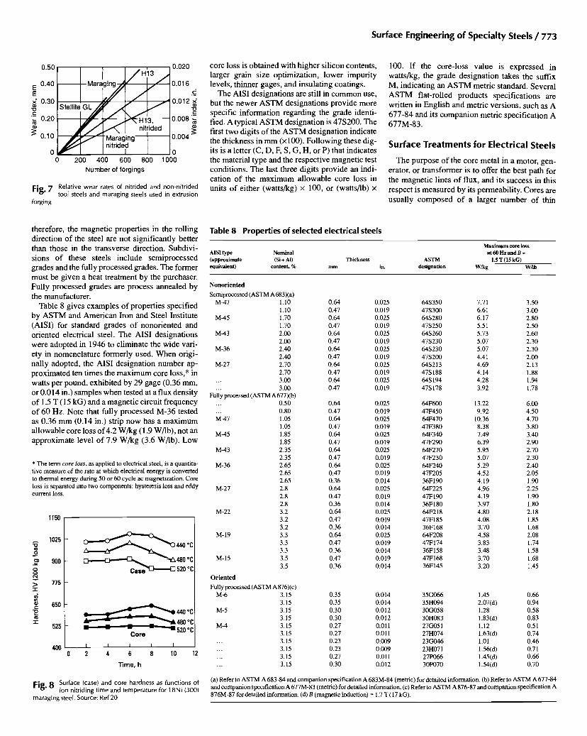
Maraging steels can also be surface hardened by ion nitriding. Ozbaysal and Inal (Ref 20) have demonstrated that the surface hardening of ma- raging steels without a reduction in core hardness is possible using the ion nitriding process. Their studies on 18Ni(250), 18Ni(300), and 18Ni(350) showed that the highest surface hardness and the highest core hardness for all three grades were achieved by nitriding at approximately 440 °C (825 °F). Figure 8 shows the surface and core hardness as functions of ion nitriding time and temperature for 300-grade maraging alloy.
Electrical Steels (Ref 21)
Electrical steels are fiat-rolled silicon-contain- ing alloys used for soft magnetic applications such as components (magnetic cores) for motors,
generators, and transformers. The beneficial ef- fects of silicon additions to iron include:
• Increase of electrical resistivity • Suppression of the 7 loop enabling desirable
grain growth • Development of preferred orientation grain
structure
The addition of silicon also reduces magne- tocrystalline anisotropy energy, and a t -6 .5% Si content reduces the magnetostriction constants to nearly zero. High-permeability and low hystere- sis losses can therefore be attained at the 6.5Si-Fe composition. On the negative side, the addition of silicon to iron lowers magnetic saturation, lowers Curie temperature, and seriously decreases me- chanical ductility. At silicon levels above ~4%, the alloy becomes brittle and difficult to process by cold-rolling methods; thus, few commercial steels contain more than -3.5% Si.
The commercial grades of silicon steel in com- mon use are made mostly in electric or basic oxygen furnaces. Continuous casting and/or vac- uum degassing (V-D) may be employed. Flat- rolled silicon-iron sheet and strip has low sulfur content, typically below 0.25%, with better grades below 0.01%. Carbon contents are fre- quently less than 0.04%. Manganese may be present up to approximately 0.70%. Residual ele- ments such as chromium, molybdenum, nickel, copper, and phosphorus may also be present. The major alloying addition is silicon plus up to 0.6% A1 (optional). These alloys are not generally sold on the basis of their composition, but rather are sold based upon controlled magnetic properties, particularly ac core losses.
Electrical sheet grades are divided into two general classifications, (1) oriented steels and (2) nonoriented steels. The oriented steels are given mill treatments designed to yield exceptionally good magnetic properties in the rolling, or length- wise, direction of the steel. Nonoriented grades are made with a mill treatment that yields a grain structure, or texture, of a random nature and,
S u r f a c e E n g i n e e r i n g o f S p e c i a l t y Steels / 7 7 3
0.50
0.40 E E x" 0.30
"10 t--
"= 0.20
• 0.10
M a r a : ~ / H I 3 / / / " .,
nitrided ~ ~ . I " Maraging
nitrided I
0 200 400 600 800 Number of forgings
0.020
0.016 . _
0.012 ~£ "13 .~_
0.008
0.004
0 1000
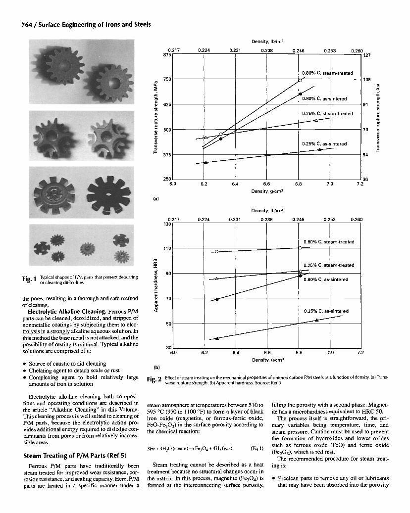
Fig. 7 Relative wear rates of nitrided and non-nitrided tool steels and maraging steels used in extrusion
forging
core loss is obtained with higher silicon contents, larger grain size optimizat ion, lower impuri ty levels, thinner gages, and insulating coatings.
The AISI designat ions are still in c o m m o n use, but the newer A S T M designat ions provide more specific information regarding the grade identi- fied. A typical A S T M designat ion is 47S200. The first two digits of the A S T M designat ion indicate the thickness in mm (x 100). Fo l lowing these dig- its is a letter (C, D, F, S, G, H, or P) that indicates the material type and the respect ive magnet ic test condit ions. The last three digits provide an indi- cation of the m a x i m u m al lowable core loss in units of ei ther (wat ts&g) x 100, or (watts/lb) x
100. If the core- loss value is expressed in watts/kg, the grade des ignat ion takes the suffix M, indicat ing an A S T M metric standard. Several A S T M fiat-rolled products specif icat ions are writ ten in Engl ish and metric versions, such as A 677-84 and its compan ion metric specif icat ion A 677M-83 .
S u r f a c e T r e a t m e n t s f o r E l e c t r i c a l Stee ls
The purpose of the core metal in a motor, gen- erator, or t ransformer is to offer the best path for the magnet ic lines o f flux, and its success in this respect is measured by its permeabil i ty. Cores are usual ly composed of a larger number of thin
therefore, the magnet ic propert ies in the rolling direct ion of the steel are not s ignif icantly better than those in the transverse direction. Subdivi- sions of these steels include semiprocessed grades and the fully processed grades. The former must be given a heat t reatment by the purchaser. Ful ly processed grades are process annealed by the manufacturer.
Table 8 gives examples o f propert ies specif ied by A S T M and Amer ican Iron and Steel Institute (AISI) for standard grades o f nonor iented and oriented electrical steel. The AISI designat ions were adopted in 1946 to el iminate the wide vari- ety in nomencla ture formerly used. W h e n origi- nally adopted, the AISI des ignat ion number ap- p roximated ten t imes the m a x i m u m core loss,* in watts per pound, exhibi ted by 29 gage (0.36 mm, or 0 .014 in.) samples when tested at a flux densi ty of 1.5 T (15 kG) and a magnet ic circuit f requency of 60 Hz. Note that fully processed M-36 tested as 0.36 m m (0.14 in.) strip now has a m a x i m u m al lowable core loss of 4.2 W / k g (1.9 W/lb) , not an approximate level of 7.9 W/kg (3.6 W/lb). Low
* The term core loss, as applied to electrical steel, is a quantita- tive measure of the rate at which electrical energy is converted to thermal energy during 50 or 60 cycle ac magnetization. Core loss is separated into two components: hysteresis loss and eddy current loss.
1150
A
lID O
O O
> -1-,
C
i,,,,
"1"
1025
900
775
650
525
- ~ 4 4 0 *C
o
. . . . - " 520 *C Core
400 I I I I I 0 2 4 6 8 10 12
"lime, h
Fig. 8 Surface (case) and core hardness as functions of ion nitriding time and temperature for 18Ni (300)
maraging steel. Source: Ref 20
Table 8 Properties of selected electrical steels
AISI type Nominal (approximate (Si + AI) Thickness ASTM equivalent) content, % mm in. designation
Maximum core loss at 60 Hz and B =
1.5 T (15 kG)
W/kg W/lb
Nonoriented
Semiprocessed (ASTM A 683)(a) M-47 1.10 0.64 0.025 64S350 7.71 3.50
1.10 0.47 0.019 47S300 6.61 3.00 M-45 1.70 0.64 0.025 64S280 6.17 2.80
1.70 0.47 0.019 47S250 5.51 2.50 M-43 2.00 0.64 0.025 64S260 5.73 2.60
2.00 0.47 0.019 47S230 5.07 2.30 M-36 2.40 0.64 0.025 64S230 5.07 2.30
2.40 0.47 0.019 47S200 4.41 2.00 M-27 2.70 0.64 0.025 64S213 4.69 2.13
2.70 0.47 0.019 47S 188 4.14 1.88 ... 3.00 0.64 0.025 64S194 4.28 1.94
3.00 0.47 0.019 47S178 3.92 1.78 . . .
Fully processed (ASTM A 677)(b) ... 0.50 0.64 0.025 64F600 13.22 6.00
0.80 0.47 0.019 47F450 9.92 4.50 M-47 1.05 0.64 0.025 64F470 10.36 4.70
1.05 0.47 0.019 47F380 8.38 3.80 M-45 1.85 0.64 0.025 64F340 7.49 3.40
1.85 0.47 0.019 47F290 6.39 2.90 M-43 2.35 0.64 0.025 64F270 5.95 2.70
2.35 0.47 0.019 47F230 5.07 2.30 M-36 2.65 0.64 0.025 64F240 5.29 2.40
2.65 0.47 0.019 47F205 4.52 2.05 2.65 0.36 0.014 36F 190 4.19 1.90
M-27 2.8 0.64 0.025 64F225 4.96 2.25 2.8 0.47 0.019 47F190 4.19 1.90 2.8 0.36 0.014 36F180 3.97 1.80
M-22 3.2 0.64 0.025 64F218 4.80 2.18 3.2 0.47 0.019 47F185 4.08 1.85 3.2 0.36 0.014 36F168 3.70 1.68
M-19 3.3 0.64 0.025 64F208 4.58 2.08 3.3 0.47 0.019 47F174 3.83 1.74 3.3 0.36 0.014 36F158 3.48 1.58
M- 15 3.5 0.47 0.019 47F 168 3.70 1.68 3.5 0.36 0.014 36F145 3.20 1.45
Oriented
Fully processed (ASTM A 876)(c) M-6 3.15 0.35 0.014 35G066 1.45 0.66
3.15 0.35 0.014 35H094 2.07(d) 0.94 M-5 3.15 0.30 0.012 30G058 1.28 0.58
3.15 0.30 0.012 30H083 1.83(d) 0.83 M-4 3.15 0.27 0.011 27G051 1.12 0.51
3.15 0.27 0.011 27H074 1.63(d) 0.74 ... 3.15 0.23 0.009 23G046 1.01 0.46 ... 3.15 0.23 0.009 23H071 1.56(d) 0.71 ... 3.15 0.27 0.011 27P066 1.45(d) 0.66 ... 3.15 0.30 0.012 30P070 1.54(d) 0.70
(a) Refer to ASTM A 683-84 and companion specification A 683M-84 (metric) for detailed information. (b) Refer to ASTM A 677-84 and companion specification A 677M-83 (metric) for detailed information. (c) Refer to ASTM A 876-87 and companion specification A 876M-87 for detailed information. (d) B (magnetic induction) = 1.7 T (17 kG).

774 / Surface Engineering of Irons and Steels
Table 9 Types of core plate coatings used for lowering core losses in electrical steels
Core plate designation Description
C-1
C-2
C-3
C-4
C-5
An organic enamel or varnish coating sometimes used for cores not immersed in oil. It enhances punchability and is resistant to ordinary operating temperatures. It will not withstand stress-relief annealing.
An inorganic insulation consisting of a glass-like film formed during the high-temperature annealing of electrical steel, particularly grain-oriented electrical steel, as the result of the reaction of an applied coating of MgO and silicates in the surface of the steel. This insulation is intended for air-cooled or oil-immersed cores. It will withstand stress-relief annealing and has sufficient interlamination resistance for wound cores of narrow-width strip such as in distribution transformers. It is not intended for stamped lamination because it is abrasive to dies.
An enamel or varnish coating intended for air-cooled or oil-immersed cores. C-3 enhances punchability and is resistant to normal operating temperatures. It will not withstand stress-relief annealing.
Consists of a chemically treated or phosphated surface useful for air-cooled or oil-immersed cores. It will withstand stress- relief annealing in relatively neutral atmospheres.
An inorganic insulation similar to C-4 but with ceramic fillers (such as colloidal silica) added to increase the eleclrical insulation properties. C-5 can be used in air-cooled or oil-immersed cores and will endure stress-relief annealing.
Source: ASTM A 345
0.65
0.55 m
~" 0.45 O m
0.35 L_
O O
N 0.25 - ir-
O r,D 0.15
0.05
__~- Laser treated
I I I I 9 11 13 15 17 19
Test induction, kG
Fig. 9 Effect of laser scribing on the core loss of a high- permeability grain-oriented electrical steel.
Source: Ref 23
metal laminations that are fabricated by punching from thin sheets of metal, and which are sub- sequently assembled to form a core.
Interlaminar insulation is necessary for high electrical efficiency in the magnetic core, whether the application is static or rotating. For small cores used in fractional-horsepower mo- tors, an oxide surface on the laminations may insulate the core adequately. Insulations of AISI types C-I , C-2, C-3, C-4, and C-5 are used for more rigorous requirements. Table 9 describes the characteristics of these various core coatings.
Organic-Type Insulation. Types C-1 and C-3 are organic and cannot be successfully applied to. laminations before annealing. They are unsuitable for electrical equipment operated at high tempera- tures or for power transformers with certain types of coolants. However, they improve the punchability of the sheet steel.
Inorganic-Type Insulat ion. Inorganic types C-4 and C-5 are used when insulation requirements are severe and when annealing temperatures up to 790 °C (1450 °F) must be withstood. Typical values of interlaminar resistance for these two types are between 3 and 100 f~. cm/lamination under a pres- sure of 2070 kPa (300 psi). These coatings also can be made to impart residual tensile stresses in the steel substrate, which can improve magnetic prop- erties.
Core insulation must be sufficiently thin and uniform so as to have no more than 2.0% effect on the lamination factor (solidity of the core). To calculate the required insulation for most opera- tions at power frequency, the square of the resis- tivity, in ohm-centimeters per lamination, should at least equal the square of the width of the mag- netic path, in inches. This usually ensures a neg- ligible interlaminar loss that is less than 1.0% of the core loss.
C e r a m i c Films. Japanese electrical steel pro- ducers have reported significant improvement in core loss as a result of ion plating of TiN and CrN ceramic coatings (Ref 22). Application of these ce- ramic f'tlrns on chemically polished grain-oriented electrical steel sheet increased the magnetic flux density by 0.004 to 0.015 T (0.04 to 0.15 kG) and lowered the core loss by 0.12 to 0.20 W/kg (0.05 to 0.09 W/lb). By laser domain refining (see discus- sion below), it was possible to further improve the core loss by 0.04 to 0.09 W/kg (0.02 to 0.04 W/lb). Using this dual ceramic filmAaser treatment, electri- cal steels with original core losses of 0.88 W/kg (0.4 W/lb) were improved to an ultralow core loss of 0.55 W/kg (0.25 W/lb), which corresponds to an improvement of about 40% (Ref 22).
Laser M a g n e t i c D o m a i n Re f inem ent . Core loss improvements of 2 to 14% can be achieved by rapid scanning (typically 100 m/s, or 325 R/s) a high-powered focused laser beam across the surface (transverse to the rolling direction) of grain-oriented glass-coated (Si-Mg-P-AI glass) 3% silicon-irons (Ref 23). There is no flame, spark, or smoke gener- ated during this process, which is also referred to as laser scribing, and the material/coating shows no visible surface change. The improvement in core loss is due to a thermal shock imparted to the micro- structure which causes slip plane dislocations to form, thereby producing new magnetic domain wall boundaries (Ref 23). By adjusting the spacing of the scanned laser lines, the energy lost due to moving domain walls back and forth under the action of the applied ac field in the transformer is minimized. The laser lines restrict the length of the domains and also act to control the width of the domains. Thus by adjusting the spacing of the laser lines, the domain sizes can be controlled, i.e., refined. Figure 9 illus- trates the improvement in core loss as a function of
applied field strength for a 0.26 mm (0.0104 in.) thick silicon steel sheet.
REFERENCES
1. L.E Pease 111, Ferrous Powder Metallurgy Ma- terials, Properties and Selection: Irons, Steels, and High-Performance Alloys, Vol 1, ASM Handbook, ASM Intemational, 1990, p 801- 821
2. W.B. James, M.J. McDermott, and R.A. Pow- ell, Powder Forging, Forming and Forging, Vol 14, ASM Handbook (formerly 9th ed., Metals Handbook), ASM Intemational, 1988, p 188- 211
3. Materials Standards for P/M Structural Parts, MPIF Standard 35, Metal Powder Industries Federation, 1990
4. H.E. Boyer, Secondary Operations Performed on P/M Parts and Products, Powder Metallurgy, Vol 7,ASMHandbook (formerly 9th ed., Metals Handbook), ASM Intemational, 1984, p 451- 462
5. H.A. Ferguson, Heat Treating of Powder Met- allurgy Steels,Heat Treating, Vol 4, ASM Hand- book, 1991, p 229-236
6. L.E Pease 111, Mechanical Properties of Steam Blackened P/M Materials, in Modern Develop- ments in Powder Metallurgy: Proceedings of the International Powder Metallurgy Confer- ence, Metal Powder Industries Federation, 1988
7. W. Rembges, Ion Nitriding Applications Grow for Automotive Components, Heat Treat., March 1990
8. A.M. Bayer, Wrought Tool Steels, Properties and Selection: Irons, Steels, and High-Perform- ance Alloys, Vol 1, ASM Handbook (formerly 10th ed., Metals Handbook), ASM Intema- tional, 1990, p 757-779
9. K.E. Pinnow and W. Stasko, P/M Tool Steels, Properties and Selection: Irons, Steels, and High-Performance Alloys, Vol 1, ASM Hand- book (formerly 10th ed., Metals Handbook), ASM Intemational, 1990, p 780-792
10. J.L. Maloney 111, Friction and Wear of Tool Steels, Friction, Lubrication, and Wear Tech- nology, Vol 18, ASM Handbook, ASM Intema- tional, 1992, p 734-740
11. H.C. Fiedler and R.J. Sieraski, Boriding Steels for Wear Resistance, Met. Prog., Feb 1971, p 102-103
12. O.N. Guy, Boronizing--A Surface Heat Treat- ment for Critical Wear Surfaces, New Develop- ments in Tool Materials and Applications, Blinois Institute of Technology, 1977
13. T.D. Deming, Steam Treating Emerges as Im- portant Cog in Metal Surface Engineering, In- dustrial Heating, Jan 1990, p 28-30
14. E Wendl, Current Trends in Surface Treatment of Tools Used for Plastics Processing, Thyssen Edelstahl Tech. Ber., special issue, May 1990, p 82-99
15. H.A. Sundquist, E.H. Sirvio, and M.T. Kurki- nen, Wear of Metalworking Tools Ion Plated "O¢-lth Tltanium Nitride, Met. Tech., Vo110, 1983, p 130-134

Surface Engineering of Specialty Steels / 775
16. C. Wick, HSS Cutting Tools Gain a Productiv- ity Edge, Manufacturing Engineering, May 1987, p 38
17. G.R. Fenske, Ion Implantation, Friction, Lubrica- tion, and Wear Technology, Vol 18, ASM Hand- book, ASM International, 1992, p 850-860
18. M. Hsu and P.A. Molian, Wear, Vol 127, 1988, p 253
19. K. Rohrbach and M. Schmidt, Maraging Steels, Properties and Selection: Irons, Steels, and
High-Performance Alloys, Vol 1, ASM Hand- book (formerly 10th ed., Metals Handbook), ASM Intemational, 1990, p 793-800
20. K. Ozbaysal and O.T. Inal, Surface Hardening of Marage Steels by Ion Nitriding without Re- duction in Core Hardness, in Ion Nitriding, ASM Intemational, 1986, p 97-115
21. D.W. Dietrich, Magnetically Soft Materials, Properties and Selection: Nonferrous Alloys and Special-Purpose Materials, Vol 2, ASM
Handbook (formerly 10th ed., Metals Hand- book), ASM Intemational, 1990, p 761-781
22. Y. Inokuti, K. Suzuki, and Y. Kobayashi, Grain Oriented Silicon Steel Sheet With New Ce- ramic Films Chamcterize_A by Ultra-Low Iron Loss, Materials Transactions, J/M, Vo133 (No. 10), 1992, p 946-952
23. G.L. Neiheisel, Laser Magnetic Domain Re- finement, LIA Vol 44, Proc. Conf. ICALEO 1984, p 102-111