Embed Size (px)
Citation preview
SUPPORTING REPORT (2)
ANNEX 8 : PRELIMINARY DESIGN
i
THE STUDY ON STORM WATER DRAINAGE PLAN FOR THE COLOMBO METROPOLITAN REGION
IN THE DEMOCRATIC SOCIALIST REPUBLIC OF SRI LANKA
FINAL REPORT
VOLUME IV : SUPPORTING REPORT (2)
ANNEX 8 : PRELIMINARY DESIGN
TABLE OF CONTENTS
Page
CHAPTER 1 GENERAL.....................................................................................A8-1 CHAPTER 2 WERAS GANGA SCHEME 2.1 Dredging of Weras Ganga ...............................................................................A8-2 2.2 Wet Masonry Dike ..........................................................................................A8-3 2.3 Sluiceway in Retention Pond...........................................................................A8-3 2.4 Periphery Canal for Storm Water Retention Area ..........................................A8-3 CHAPTER 3 BOLGODA CANAL SCHEME...................................................A8-5 CHAPTER 4 NUGEGODA-RATTANAPITIYA SCHEME 4.1 Rattanapitiya Ela Channel Improvement ........................................................A8-7 4.2 Delkanda Ela Channel Improvement ..............................................................A8-8 4.3 Nugegoda Ela Channel Improvement..............................................................A8-9 CHAPTER 5 RATMALANA-MORATUWA SCHEME ..................................A8-12
ii
LIST OF TABLES
Page
Table 3.1.1 Principal Features of Proposed Bridges and Culverts.....................A8-T1
LIST OF DRAWINGS
Page
Drawing 1 General Plan of Proposed Channel Improvement Reaches in Weras Ganga Basin ........................................................................A8-D1
Drawing 2 Plan of Proposed Weras Ganga Dredging (1/4) .............................A8-D2 Drawing 3 Plan of Proposed Weras Ganga Dredging (2/4) .............................A8-D3 Drawing 4 Plan of Proposed Weras Ganga Dredging (3/4) .............................A8-D4 Drawing 5 Plan of Proposed Weras Ganga Dredging (4/4) .............................A8-D5 Drawing 6 Longitudinal Profile of Proposed Weras Ganga Dredging .............A8-D6 Drawing 7 Typical Cross Section of Proposed Weras Ganga Dredging...........A8-D7 Drawing 8 Plan of Proposed Bolgoda Canal Improvement (1/2) ....................A8-D8 Drawing 9 Plan of Proposed Bolgoda Canal Improvement (2/2) ....................A8-D9 Drawing 10 Longitudinal Profile of Proposed Bolgoda Canal Improvement ....A8-D10 Drawing 11 Typical Cross Section of Proposed Bolgoda Canal
Improvement ..................................................................................A8-D11 Drawing 12 Plan of Proposed Rattanapitiya Ela and Delkanda Ela
Channel Improvement (1/3) ...........................................................A8-D12 Drawing 13 Plan of Proposed Rattanapitiya Ela and Delkanda Ela
Channel Improvement (2/3) ...........................................................A8-D13 Drawing 14 Plan of Proposed Rattanapitiya Ela and Delkanda Ela
Channel Improvement (3/3) ...........................................................A8-D14 Drawing 15 Longitudinal Profile of Proposed Rattanapitiya Ela and
Delkanda Ela Channel Improvement .............................................A8-D15 Drawing 16 Typical Cross Section of Proposed Rattanapitiya Ela and
Delkanda Ela Channel Improvement .............................................A8-D16 Drawing 17 Plan of Proposed Nugegoda Ela Channel Improvement ................A8-D17 Drawing 18 Longitudinal Profile of Proposed Nugegoda Ela
Channel Improvement ....................................................................A8-D18 Drawing 19 Typical Cross Section of Proposed Nugegoda Ela
Channel Improvement ....................................................................A8-D19 Drawing 20 Plan of Proposed Urban Drainage Improvement of
Ratmalana-Moratuwa Scheme (1/2) ..............................................A8-D20

iii
Drawing 21 Plan of Proposed Urban Drainage Improvement of Ratmalana-Moratuwa Scheme (2/2) ..............................................A8-D21
Drawing 22 Typical Cross Sections of Proposed Urban Drainage Improvement of Ratmalana-Moratuwa Scheme ..........................A8-D22
Drawing 23 Typical Design of Proposed Bridge ................................................A8-D23 Drawing 24 Typical Design of Propsed Culvert of Delkanda Ela......................A8-D24 Drawing 25 Typical Design of Outlet Sluiceway for Retention Pond................A8-D25 Drawing 26 Typical Cross Sections of Proposed Wet Masonry Dike,
Maintenance Road and Periphery Canal........................................A8-D26

Final Report, Volume IV Feasibility Study Supporting Report (2) Annex 8, Chapter 1
Nippon Koei Co., Ltd. A8 - 1 The Study on Storm Water Drainage Plan for the Colombo Metropolitan Region
CHAPTER 1 GENERAL
The preliminary design for the Feasibility Study is executed based on the design criteria described in Annex 9 of Volume III: Supporting Report (1).
This report describes the preliminary design for the projects of Weras Ganga Scheme, Bolgoda Canal Scheme, Nugegoda-Rattanapitiya Scheme and Ratmalana-Moratuwa Scheme in Weras Ganga basin, which were selected as priority projects. The general plan of channel improvement reaches in the Weras Ganga basin is shown in Drawing 1.
Work quantities of the proposed Weras Ganga storm water drainage project are presented in Annex 9 of Volume IV: Supporting Report (2).
Final Report, Volume IV Feasibility Study Supporting Report (2) Annex 8, Chapter 2
Nippon Koei Co., Ltd. A8 - 2 The Study on Storm Water Drainage Plan for the Colombo Metropolitan Region
CHAPTER 2 WERAS GANGA SCHEME
2.1 Dredging of Weras Ganga
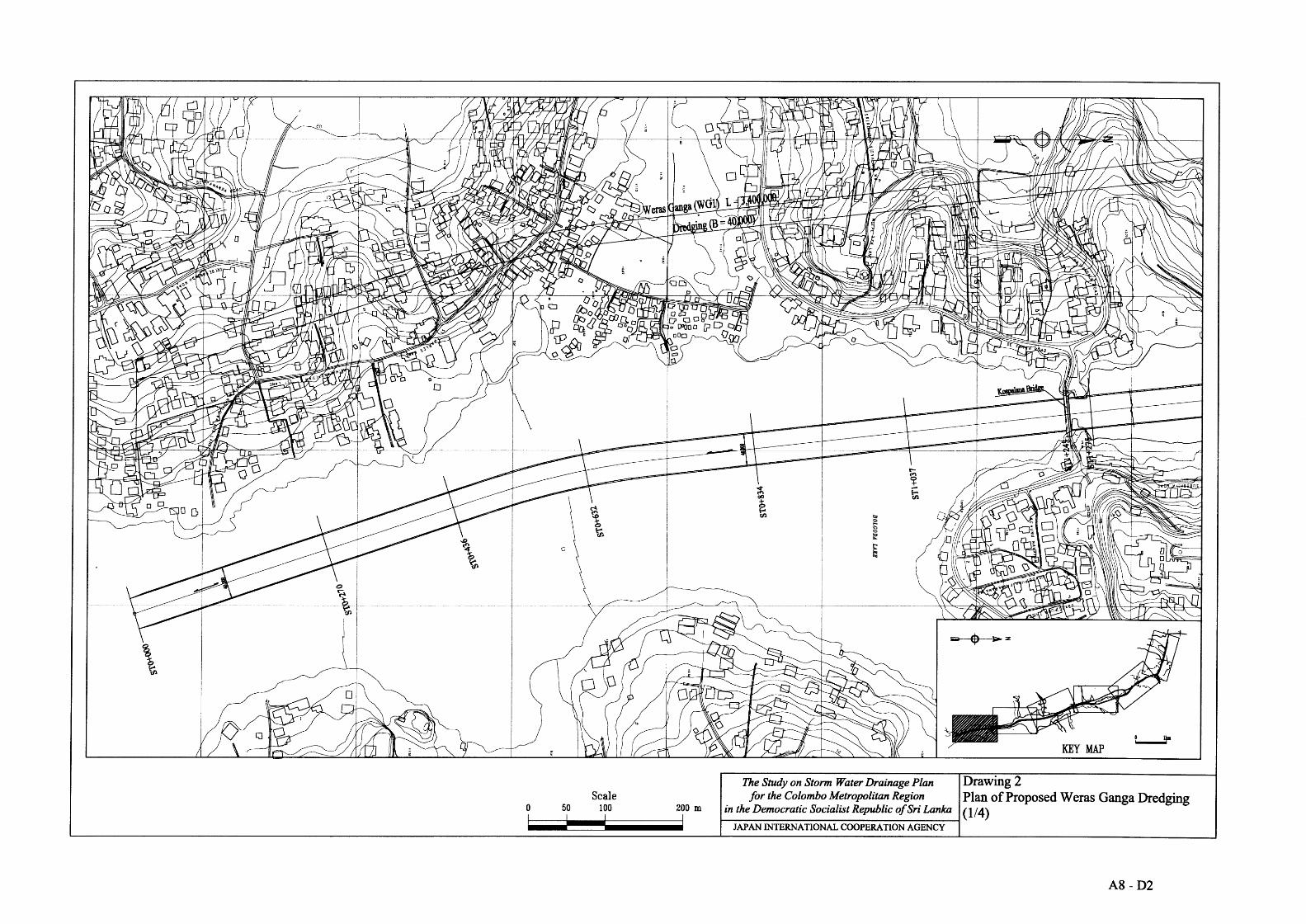
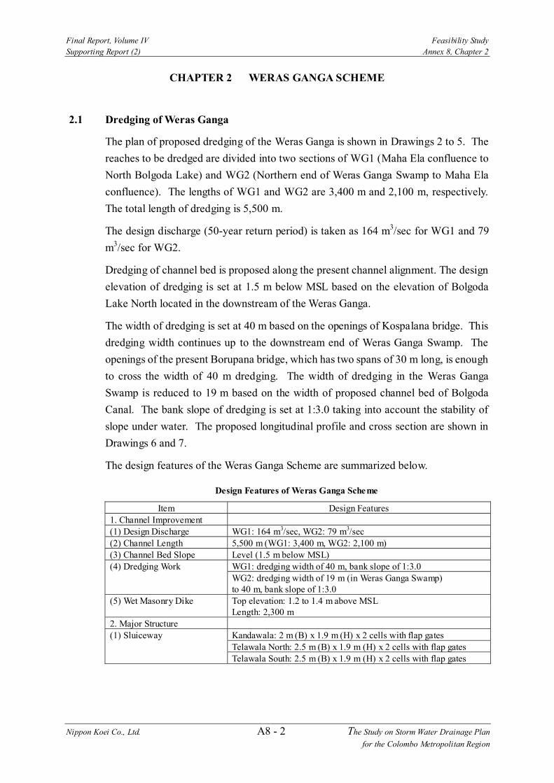
The plan of proposed dredging of the Weras Ganga is shown in Drawings 2 to 5. The reaches to be dredged are divided into two sections of WG1 (Maha Ela confluence to North Bolgoda Lake) and WG2 (Northern end of Weras Ganga Swamp to Maha Ela confluence). The lengths of WG1 and WG2 are 3,400 m and 2,100 m, respectively. The total length of dredging is 5,500 m.
The design discharge (50-year return period) is taken as 164 m3/sec for WG1 and 79 m3/sec for WG2.
Dredging of channel bed is proposed along the present channel alignment. The design elevation of dredging is set at 1.5 m below MSL based on the elevation of Bolgoda Lake North located in the downstream of the Weras Ganga.
The width of dredging is set at 40 m based on the openings of Kospalana bridge. This dredging width continues up to the downstream end of Weras Ganga Swamp. The openings of the present Borupana bridge, which has two spans of 30 m long, is enough to cross the width of 40 m dredging. The width of dredging in the Weras Ganga Swamp is reduced to 19 m based on the width of proposed channel bed of Bolgoda Canal. The bank slope of dredging is set at 1:3.0 taking into account the stability of slope under water. The proposed longitudinal profile and cross section are shown in Drawings 6 and 7.
The design features of the Weras Ganga Scheme are summarized below.
Design Features of Weras Ganga Scheme
Item Design Features 1. Channel Improvement (1) Design Discharge WG1: 164 m3/sec, WG2: 79 m3/sec (2) Channel Length 5,500 m (WG1: 3,400 m, WG2: 2,100 m) (3) Channel Bed Slope Level (1.5 m below MSL) (4) Dredging Work WG1: dredging width of 40 m, bank slope of 1:3.0 WG2: dredging width of 19 m (in Weras Ganga Swamp)
to 40 m, bank slope of 1:3.0 (5) Wet Masonry Dike Top elevation: 1.2 to 1.4 m above MSL Length: 2,300 m 2. Major Structure (1) Sluiceway Kandawala: 2 m (B) x 1.9 m (H) x 2 cells with flap gates Telawala North: 2.5 m (B) x 1.9 m (H) x 2 cells with flap gates Telawala South: 2.5 m (B) x 1.9 m (H) x 2 cells with flap gates
Final Report, Volume IV Feasibility Study Supporting Report (2) Annex 8, Chapter 2
Nippon Koei Co., Ltd. A8 - 3 The Study on Storm Water Drainage Plan for the Colombo Metropolitan Region
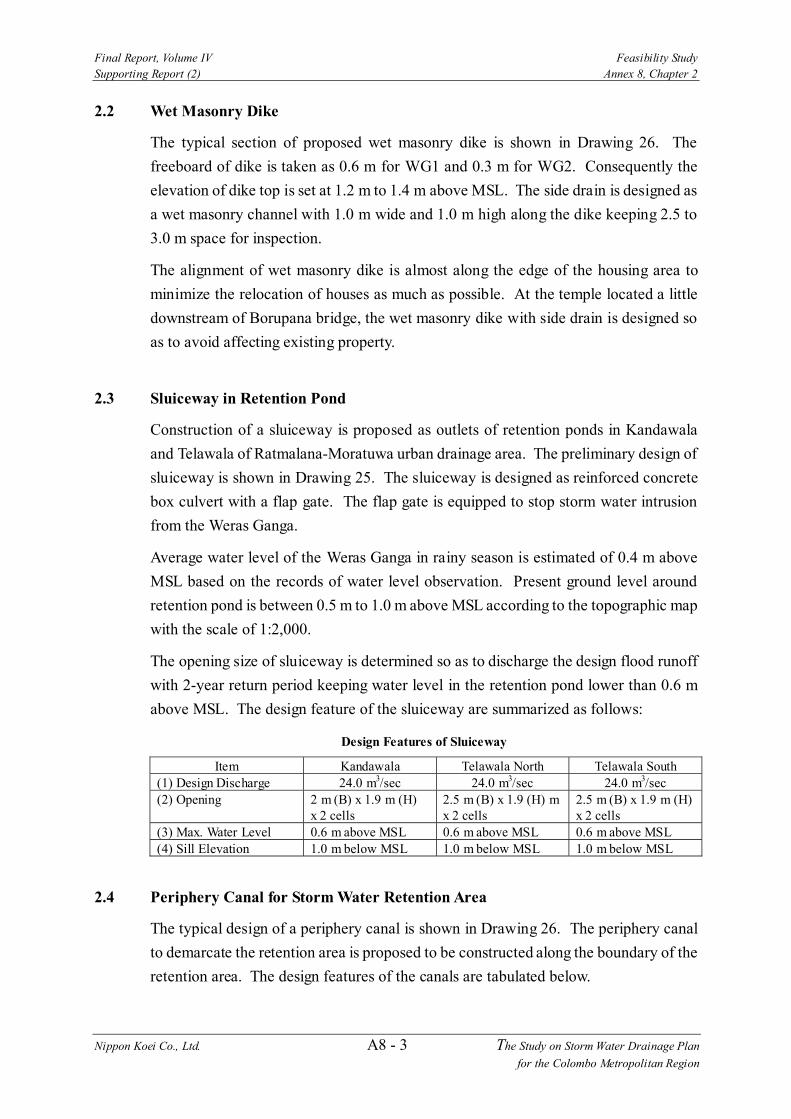
2.2 Wet Masonry Dike
The typical section of proposed wet masonry dike is shown in Drawing 26. The freeboard of dike is taken as 0.6 m for WG1 and 0.3 m for WG2. Consequently the elevation of dike top is set at 1.2 m to 1.4 m above MSL. The side drain is designed as a wet masonry channel with 1.0 m wide and 1.0 m high along the dike keeping 2.5 to 3.0 m space for inspection.
The alignment of wet masonry dike is almost along the edge of the housing area to minimize the relocation of houses as much as possible. At the temple located a little downstream of Borupana bridge, the wet masonry dike with side drain is designed so as to avoid affecting existing property.
2.3 Sluiceway in Retention Pond
Construction of a sluiceway is proposed as outlets of retention ponds in Kandawala and Telawala of Ratmalana-Moratuwa urban drainage area. The preliminary design of sluiceway is shown in Drawing 25. The sluiceway is designed as reinforced concrete box culvert with a flap gate. The flap gate is equipped to stop storm water intrusion from the Weras Ganga.
Average water level of the Weras Ganga in rainy season is estimated of 0.4 m above MSL based on the records of water level observation. Present ground level around retention pond is between 0.5 m to 1.0 m above MSL according to the topographic map with the scale of 1:2,000.
The opening size of sluiceway is determined so as to discharge the design flood runoff with 2-year return period keeping water level in the retention pond lower than 0.6 m above MSL. The design feature of the sluiceway are summarized as follows:
Design Features of Sluiceway
Item Kandawala Telawala North Telawala South (1) Design Discharge 24.0 m3/sec 24.0 m3/sec 24.0 m3/sec (2) Opening 2 m (B) x 1.9 m (H)
x 2 cells 2.5 m (B) x 1.9 (H) m x 2 cells
2.5 m (B) x 1.9 m (H) x 2 cells
(3) Max. Water Level 0.6 m above MSL 0.6 m above MSL 0.6 m above MSL (4) Sill Elevation 1.0 m below MSL 1.0 m below MSL 1.0 m below MSL
2.4 Periphery Canal for Storm Water Retention Area
The typical design of a periphery canal is shown in Drawing 26. The periphery canal to demarcate the retention area is proposed to be constructed along the boundary of the retention area. The design features of the canals are tabulated below.

Final Report, Volume IV Feasibility Study Supporting Report (2) Annex 8, Chapter 2
Nippon Koei Co., Ltd. A8 - 4 The Study on Storm Water Drainage Plan for the Colombo Metropolitan Region
Design Features of Periphery Canal
Item Design Features (1) Canal Section Trapezoidal earth channel with bank slope of 1:1.0 Canal bed width: 2 m Channel Depth: 1.5 m Earth dike: 0.5 m height, dike top of 3 (2) m wide (2) Canal Length Upper Nugegoda Ela Marsh: 1,780 m Lower Nugegoda Ela Marsh: 2,110 m Delkanda Ela Marsh: 1,800 m Bellanwila-Attidiya Marsh: 4,400 m Weras Ganga Swamp: 4,400 m Maha Ela Marsh and Lowland: 6,000 m
Final Report, Volume IV Feasibility Study Supporting Report (2) Annex 8, Chapter 3
Nippon Koei Co., Ltd. A8 - 5 The Study on Storm Water Drainage Plan for the Colombo Metropolitan Region
CHAPTER 3 BOLGODA CANAL SCHEME
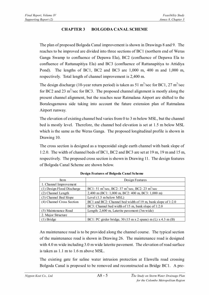
The plan of proposed Bolgoda Canal improvement is shown in Drawings 8 and 9. The reaches to be improved are divided into three sections of BC1 (northern end of Weras Ganga Swamp to confluence of Depawa Ela), BC2 (confluence of Depawa Ela to confluence of Rattanapitiya Ela) and BC3 (confluence of Rattanapitiya to Attidiya Pond). The lengths of BC1, BC2 and BC3 are 1,000 m, 400 m and 1,000 m, respectively. Total length of channel improvement is 2,400 m.
The design discharge (10-year return period) is taken as 51 m3/sec for BC1, 27 m3/sec for BC2 and 23 m3/sec for BC3. The proposed channel alignment is mostly along the present channel alignment, but the reaches near Ratmalana Airport are shifted to the Boralesgamuwa side taking into account the future extension plan of Ratmalana Airport runway.
The elevation of existing channel bed varies from 0 to 3 m below MSL, but the channel bed is mostly level. Therefore, the channel bed elevation is set at 1.5 m below MSL which is the same as the Weras Ganga. The proposed longitudinal profile is shown in Drawing 10.
The cross section is designed as a trapezoidal single earth channel with bank slope of 1:2.0. The width of channel beds of BC1, BC2 and BC3 are set at 19 m, 19 m and 15 m, respectively. The proposed cross section is shown in Drawing 11. The design features of Bolgoda Canal Scheme are shown below.
Design Features of Bolgoda Canal Scheme
Item Design Features 1. Channel Improvement (1) Design Flood Discharge BC1: 51 m3/sec, BC2: 37 m3/sec, BC2: 23 m3/sec (2) Channel Length 2,400 m (BC1: 1,000 m, BC2: 400 m, BC3: 1,000 m) (3) Channel Bed Slope Level (1.5 m below MSL) (4) Channel Cross Section BC1 and BC2: Channel bed width of 19 m, bank slope of 1:2.0 BC3: Channel bed width of 15 m, bank slope of 1:2.0 (5) Maintenance Road Length: 2,600 m, Laterite pavement (3m wide) 2. Major Structure (1) Bridge BC1: PC girder bridge, 30 (15 m x 2 spans) m (L) x 4.3 m (B)
An maintenance road is to be provided along the channel course. The typical section of the maintenance road is shown in Drawing 26. The maintenance road is designed with 4.0 m wide including 3.0 m wide laterite pavement. The elevation of road surface is taken as 1.1 m to 1.6 m above MSL.
The existing gate for saline water intrusion protection at Elawella road crossing Bolgoda Canal is proposed to be removed and reconstructed as Bridge BC1. A pre-

Final Report, Volume IV Feasibility Study Supporting Report (2) Annex 8, Chapter 3
Nippon Koei Co., Ltd. A8 - 6 The Study on Storm Water Drainage Plan for the Colombo Metropolitan Region
stressed concrete girder bridge is proposed based on the recommendation of RDA employing an in-situ concrete pile with 600 mm diameter for the foundation. The elevation of supporting layer is assumed to be at 6 m below MSL based on the geo-technical investigation. The preliminary design of proposed bridge is shown in Drawing 23 and structural features are summarized in Table 3.1.1.

Final Report, Volume IV Feasibility Study Supporting Report (2) Annex 8, Chapter 4
Nippon Koei Co., Ltd. A8 - 7 The Study on Storm Water Drainage Plan for the Colombo Metropolitan Region
CHAPTER 4 NUGEGODA-RATTANAPITIYA SCHEME
4.1 Rattanapitiya Ela Channel Improvement
The plan of proposed Rattanapitiya Ela channel improvement is shown in Drawings 12 and 13. The reaches to be improved are divided into two sections of RE1 (confluence of Bolgoda Canal to boundary of Bellanwila-Attidiya Marsh) and RE2 (boundary of Bellanwila-Attidiya Marsh to confluence of Nugegoda Ela and Delkanda Ela). The lengths of RE1 and RE2 are 890 m and 1,240 m, respectively. The total length of channel improvement is 2,130 m. The upstream end of Rattanapitiya Ela is extended 600 m upstream from the present point because of change of confluence of Nugegoda Ela and Delkanda Ela.
The design discharge (10-year return period) is taken as 25 m3/sec for RE1 and 53 m3/sec for RE2. The proposed channel alignment is set along the present one. The proposed channel bed slope of RE1 is set at 1/1,200 against the present slope of 1/1,500, while that of RE2 is set at 1/800 against the present slope of 1/600. The proposed longitudinal profile is shown in Drawing 15.
The cross section is designed as trapezoidal earth channel with bank slope of 1:2.0 for RE1 and rectangular channel with gabion revetment for RE2 to minimize the relocation of houses. The width of channel bed is taken as 19 m for the both sections. The proposed cross section is shown in Drawing 16. The design features of Rattanapitiya Ela channel improvement are tabulated below.
Design Features of Rattanapitiya Ela Channel Improvement
Work Item Design Features 1. Channel Improvement (1) Design Discharge RE1: 25 m3/sec, RE2: 53 m3/sec (2) Channel Length 2,130 m (RE1: 890 m, RE2: 1,240 m) (3) Channel Bed Slope RE1: Level to 1/1,200, RE2:1/800 (4) Channel Cross Section RE1: Channel bed width of 19 m, bank slope of 1:2.0 RE2: Channel bed width of 19 m, Gabion revetment (5) Maintenance Road Length: 2,130 m, Laterite pavement (3 m wide) 2. Major Structure (1) Bridge RE1: PC girder bridge, 29 (14.5 m x 2 spans) m (L) x 7.4 m (B) RE2: PC girder bridge, 19 m (L) x 22 m (B) x 1 span RE3: PC girder bridge, 19 m (L) x 4 m (B) x 1 span RE4: PC girder bridge, 19 m (L) x 5 m (B) x 1 span RE5: PC girder bridge, 19 m (L) x 5 m (B) x 1 span
An maintenance road is to be provided along the channel course. The maintenance road is designed to be 4 m wide including 3 m wide laterite pavement. The elevation of road surface is taken as 1.5 m to 3.6 m above MSL.

Final Report, Volume IV Feasibility Study Supporting Report (2) Annex 8, Chapter 4
Nippon Koei Co., Ltd. A8 - 8 The Study on Storm Water Drainage Plan for the Colombo Metropolitan Region
The existing crossing structures of bridge and culvert are to be reconstructed due to insufficient span against proposed channel width. A pre-stressed concrete girder bridge is proposed based on the recommendation of RDA. An in-situ concrete pile with 600 mm diameter is applied for the foundation of proposed bridge. The elevation of supporting layer is assumed to be 6 m to 8 m below MSL based on the geo-technical investigation. The preliminary design of proposed bridge is shown in Drawing 23 and structural features are summarized in Table 3.1.1.
4.2 Delkanda Ela Channel Improvement
The plan of proposed Delkanda Ela channel improvement is shown in Drawings 13 and 14. The reaches to be improved are divided into three sections of D1 (confluence of Rattanapitiya to diversion point), D2 (diversion point to Pengiriwatta Road) and D3 (Pengiriwatta Road to upper end point at 150 m downstream of railway crossing). The lengths of D1, D2 and D3 are 280 m, 790 m and 690 m, respectively. Total length of improved section is 1,760 m.
The design discharge (10-year return period) is taken as 29 m3/sec for D1, 22 m3/sec for D2 and 14 m3/sec for D3. The proposed channel alignment is set along the present one, but a diversion channel to the present Nugegoda Ela is proposed to minimize the relocation of many houses along the lower reach of the present Delkanda Ela.
The proposed channel bed slopes of D1 and D2 are set at 1/700, while that of D3 is 1/300. They are almost same as the present channel bed slope. The proposed longitudinal profile is shown in Drawing 15.
The cross sections are designed as a trapezoidal single earth channel with bank slope of 1:2.0 for D1, a rectangular channel with gabion revetment for D2 and a trapezoidal channel with wet masonry revetment with bank slope of 1:0.5 in D3. The proposed cross sections are shown in Drawing 16. The design features of Delkanda Ela channel improvement are tabulated below.

Final Report, Volume IV Feasibility Study Supporting Report (2) Annex 8, Chapter 4
Nippon Koei Co., Ltd. A8 - 9 The Study on Storm Water Drainage Plan for the Colombo Metropolitan Region
Design Features of Delkanda Ela Channel Improvement Item Design Features
1. Channel Improvement (1) Design Discharge D1: 29 m3/sec, D2: 22 m3/sec, D3: 14 m3/sec (2) Channel Length 1,760 m (D1: 280 m, D2: 790 m, D3: 690 m) (3) Channel Bed Slope D1 and D2: 1/700, D3:1/300 (4) Channel Cross Section D1: Bed width of 13.5 m, bank slope of 1:2.0 D2: Bed width of 13.5 m, rectangular with gabion D3: Bed width of 3 m, bank slope of 1:0.5 with wet masonry (5) Maintenance Road Length: 280 m, Laterite pavement (3 m wide) 2. Major Structure (1) Bridge D1: PC girder bridge, 13.5 m (L) x 7 m (B) x 1 span D2: PC girder bridge, 13.5 m (L) x 4.2 m (B) x 1 span D3: PC girder bridge, 13.5 m (L) x 3 m (B) x 1 span D4: PC girder bridge, 13.5 m (L) x 19.8 m (B) x 1 span D5: PC girder bridge, 13.5 m (L) x 6 m (B) x 1 span (2) Culvert D6: 4.6 m (L) x 3 m (B) x 2.1 m (H) D7: 5.6 m (L) x 3 m(B) x 1.8 m (H)
A maintenance road is to be provided along the channel course. However, Old Kesbewa Road which goes alongside Delkanda Ela can be used as an maintenance road for D2. There is insufficient space to provide a maintenance road for D3 due to many houses along the channel course. The construction of a maintenance road is proposed for D1, designed to be 4 m wide including 3 m wide laterite pavement. The elevation of road surface is taken as 3.6 m to 3.8 m above MSL.
The existing crossing structures of bridge and culvert are to be reconstructed due to insufficient span of present structure against proposed channel width. A pre-stressed concrete girder bridge is proposed based on the recommendation of RDA. An in-situ concrete pile with 600 mm diameter is applied for the foundation of proposed bridge. The proposed culvert is designed as a reinforced box culvert with a driving pile 350 mm square applied for the foundation. The elevation of supporting layer is assumed to be 6 m below MSL based on the geo-technical investigation. The preliminary design of proposed bridge and culvert are shown in Drawings 23 and 24, and structural features are summarized in Table 3.1.1.
4.3 Nugegoda Ela Channel Improvement
The plan of proposed Nugegoda Ela channel improvement is shown in Drawing 17. The reaches to be improved are divided into three sections of NE1 (confluence of Rattanapitiya Ela to boundary of Lower Nugegoda Ela Marsh) and NE2 (boundary of Lower Nugegoda Ela Marsh to Pepiliyana Road) and NE3 (Pepiliyana Road to upper end at 200 m downstream of Hospital Road crossing). The lengths of NE1, NE2 and
Final Report, Volume IV Feasibility Study Supporting Report (2) Annex 8, Chapter 4
Nippon Koei Co., Ltd. A8 - 10 The Study on Storm Water Drainage Plan for the Colombo Metropolitan Region
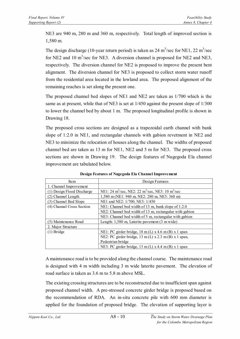
NE3 are 940 m, 280 m and 360 m, respectively. Total length of improved section is 1,580 m.
The design discharge (10-year return period) is taken as 24 m3/sec for NE1, 22 m3/sec for NE2 and 10 m3/sec for NE3. A diversion channel is proposed for NE2 and NE3, respectively. The diversion channel for NE2 is proposed to improve the present bent alignment. The diversion channel for NE3 is proposed to collect storm water runoff from the residential area located in the lowland area. The proposed alignment of the remaining reaches is set along the present one.
The proposed channel bed slopes of NE1 and NE2 are taken as 1/700 which is the same as at present, while that of NE3 is set at 1/450 against the present slope of 1/300 to lower the channel bed by about 1 m. The proposed longitudinal profile is shown in Drawing 18.
The proposed cross sections are designed as a trapezoidal earth channel with bank slope of 1:2.0 in NE1, and rectangular channels with gabion revetment in NE2 and NE3 to minimize the relocation of houses along the channel. The widths of proposed channel bed are taken as 13 m for NE1, NE2 and 5 m for NE3. The proposed cross sections are shown in Drawing 19. The design features of Nugegoda Ela channel improvement are tabulated below.
Design Features of Nugegoda Ela Channel Improvement
Item Design Features 1. Channel Improvement (1) Design Flood Discharge NE1: 24 m3/sec, NE2: 22 m3/sec, NE3: 10 m3/sec (2) Channel Length 1,580 m (NE1: 940 m, NE2: 280 m, NE3: 360 m) (3) Channel Bed Slope NE1 and NE2: 1/700, NE3: 1/450 (4) Channel Cross Section NE1: Channel bed width of 13 m, bank slope of 1:2.0 NE2: Channel bed width of 13 m, rectangular with gabion NE3: Channel bed width of 5 m, rectangular with gabion (5) Maintenance Road Length: 1,580 m, Laterite pavement (3 m wide) 2. Major Structure (1) Bridge NE1: PC girder bridge, 18 m (L) x 4.6 m (B) x 1 span NE2: PC girder bridge, 13 m (L) x 2.3 m (B) x 1 span,
Pedestrian bridge NE3: PC girder bridge, 13 m (L) x 4.4 m (B) x 1 span
A maintenance road is to be provided along the channel course. The maintenance road is designed with 4 m width including 3 m wide laterite pavement. The elevation of road surface is taken as 3.6 m to 5.8 m above MSL.
The existing crossing structures are to be reconstructed due to insufficient span against proposed channel width. A pre-stressed concrete girder bridge is proposed based on the recommendation of RDA. An in-situ concrete pile with 600 mm diameter is applied for the foundation of proposed bridge. The elevation of supporting layer is

Final Report, Volume IV Feasibility Study Supporting Report (2) Annex 8, Chapter 4
Nippon Koei Co., Ltd. A8 - 11 The Study on Storm Water Drainage Plan for the Colombo Metropolitan Region
assumed to be 6 m below MSL based on the geo-technical investigation. The preliminary design of proposed bridge is shown in Drawing 23, and structural features are summarized in Table 3.1.1.

Final Report, Volume IV Feasibility Study Supporting Report (2) Annex 8, Chapter 5
Nippon Koei Co., Ltd. A8 - 12 The Study on Storm Water Drainage Plan for the Colombo Metropolitan Region
CHAPTER 5 RATMALANA-MORATUWA SCHEME
The plan of the proposed improvement of Ratmalana-Moratuwa urban drainage system is shown in Drawings 20 and 21. In the Ratmalana-Moratuwa Scheme, major drains are to be improved. Considering limited space for construction, a type of concrete flume with cover is largely adopted to effectively use the open space on the concrete flume after construction. A wet masonry channel and a gabion channel is designed where sufficient space is available. An earth channel is applied for the lower reach of Kandawala Tributary and Telawala Tributary. The total length of main drains to be improved is 11,120 m. The widths of drains vary from 0.8 m to 6 m. The typical sections of proposed main drains are shown in Drawing 22.
At the ends of the drainage system, two ponds are provided to retard storm water. The total pond area is 13 ha and bottom elevation of ponds is taken as 1.0 m below MSL. The pond water is discharged through sluiceways with flap gates. The design features of Ratmalana-Moratuwa Scheme are tabulated below.
Design Features of Ratmalana-Moratuwa Scheme
Type Breath (mm) Height (mm) Length (m) 1. Concrete Flume with Cover 800 800 490 900 900 660 1,000 1,000 555 1,100 1,100 835 1,200 1,200 1,790 1,300 1,300 855 1,400 1,400 465 1,500 1,500 590 2,000 1,500 150 2. Wet Masonry Channel 1,000 1,000 950 along Wet Masonry Dike 1,500 1,000 200 3. Open Channel with 1,000 1,000 125 Wet Masonry Revetment 1,500 1,000 525 1,500 1,500 655 2,000 1,500 215 3,000 1,500 130 4. Open Channel with 3,000 1,500 45 Gabion Revetment 5,000 1,500 645 6,000 1,500 100 5. Earth Channel 2,000 1,500 320 5,000 1,500 105 6,000 1,500 715
Total 11,120

Tables
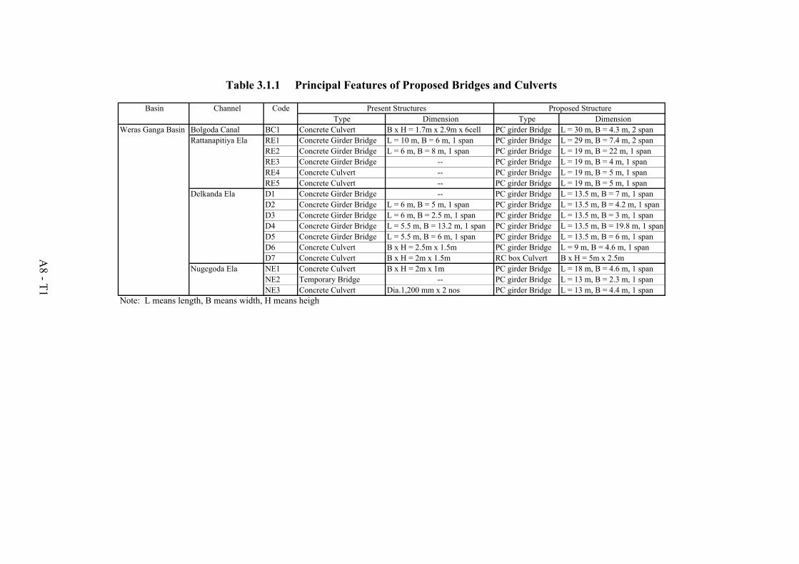
Basin Channel CodeType Dimension Type Dimension
Weras Ganga Basin Bolgoda Canal BC1 Concrete Culvert B x H = 1.7m x 2.9m x 6cell PC girder Bridge L = 30 m, B = 4.3 m, 2 spanRattanapitiya Ela RE1 Concrete Girder Bridge L = 10 m, B = 6 m, 1 span PC girder Bridge L = 29 m, B = 7.4 m, 2 span
RE2 Concrete Girder Bridge L = 6 m, B = 8 m, 1 span PC girder Bridge L = 19 m, B = 22 m, 1 spanRE3 Concrete Girder Bridge -- PC girder Bridge L = 19 m, B = 4 m, 1 spanRE4 Concrete Culvert -- PC girder Bridge L = 19 m, B = 5 m, 1 spanRE5 Concrete Culvert -- PC girder Bridge L = 19 m, B = 5 m, 1 span
Delkanda Ela D1 Concrete Girder Bridge -- PC girder Bridge L = 13.5 m, B = 7 m, 1 spanD2 Concrete Girder Bridge L = 6 m, B = 5 m, 1 span PC girder Bridge L = 13.5 m, B = 4.2 m, 1 spanD3 Concrete Girder Bridge L = 6 m, B = 2.5 m, 1 span PC girder Bridge L = 13.5 m, B = 3 m, 1 spanD4 Concrete Girder Bridge L = 5.5 m, B = 13.2 m, 1 span PC girder Bridge L = 13.5 m, B = 19.8 m, 1 spanD5 Concrete Girder Bridge L = 5.5 m, B = 6 m, 1 span PC girder Bridge L = 13.5 m, B = 6 m, 1 spanD6 Concrete Culvert B x H = 2.5m x 1.5m PC girder Bridge L = 9 m, B = 4.6 m, 1 spanD7 Concrete Culvert B x H = 2m x 1.5m RC box Culvert B x H = 5m x 2.5m
Nugegoda Ela NE1 Concrete Culvert B x H = 2m x 1m PC girder Bridge L = 18 m, B = 4.6 m, 1 spanNE2 Temporary Bridge -- PC girder Bridge L = 13 m, B = 2.3 m, 1 spanNE3 Concrete Culvert Dia.1,200 mm x 2 nos PC girder Bridge L = 13 m, B = 4.4 m, 1 span
Note: L means length, B means width, H means height
Table 3.1.1 Principal Features of Proposed Bridges and Culverts
A8 - T1
Present Structures Proposed Structure

Drawings