Embed Size (px)
Citation preview

Supporting
multi-modal and multi-medial user interfaces
from an embedded environment
Master Thesis G.J.M. Braam October 2006
Home Automation Europe
ir. A. Noorbergen
Human Media Interaction
prof. dr. ir. A. Nijholt dr. E.M.A.G. van Dijk
dr. J. Zwiers
Date first created: 03-JAN-2006 Summary:
Last modified: 13-OCT-2006
Document number: HAE-200601-001 Document revision: 1.67 Author: JB Classification: PRIVATE
This report describes my research, design and partial realization of a tech-nical framework to support multi-modal and multi-medial user interface clients from an embedded environment. This framework supports multi-ple in- and output modalities, multiple types of connection media, syn-chronization between different instances on different types of media and bi-directional communication with these user interface clients.
© Home Automation Europe BV. All rights reserved. Unless explicitly otherwise agreed in writing, Home Automation Europe reserves the right to make changes to specifications and terms in this document at any time, without notice.
G.J.M. Braam - 2 - MM & MM UI
Abstract
This report describes my research, design and partial realization of a technical fra-mework to support multi-modal and multi-medial user interface clients from an em-bedded environment. This framework supports multiple in- and output modalities, multiple types of connection media, synchronization between different instances on different types of media and bi-directional communication with these user interface clients.
I show how these user interfaces will be operated by end users and by configuration users, the latter being more technical than the first. Each has a somewhat different set of demands from the user interface that they use, although in the end the ser-vices supporting both will be based on the same basic low-level primitives.
The base framework that I have designed to support these user interfaces provides low-level functionality like message routing, event notification and connection track-ing. As a part of this base I also specify a message protocol that can handle the com-munication requirements internally within such a framework as well as externally, with the user interface clients. By means of the message protocol and the driver model I have incorporated an abstraction level over the connected devices that en-ables them to be addressed and controlled in a uniform way, resulting in a high level of modularity.
At the time of writing I have completed the framework to a point where it delivers a reliable base for message delivery and driver stability. Other driver and user interface developers, who are also seen as users of the framework, can now do their work without needing to know all the low-level information about the other parts of the framework. I have developed prototype drivers and user interface clients for differ-ent platforms and hardware standards that connect with the framework, of which the client PocketPC Flash Application is the most feature rich.
The framework is tested on a resource-limited, embedded hardware component cal-led the Home Control Box (HCB). It plays a central role in the integration all of the home automation devices in an environment, groups of devices that are often based on multiple incompatible technologies. Adding software support for new standards and technologies to the framework is therefore made to be as fast and simple as possible. Future expansion plans for the HCB include solutions in the field of ambi-ent intelligence and automated remote care.

G.J.M. Braam - 3 - MM & MM UI
Preface
My name is Jurgen Braam and this project is the final step in obtaining my masters degree in Computer Science with the cluster Human Media Interaction at the Uni-versity of Twente. The report you see before you is the result of the ten months I spent at Home Automation Europe in Amsterdam working on this project.
First I would like to thank Arjen Noorbergen and Joris Jonker for allowing me to do my final graduation project at Home Automation Europe and for allowing me my extremely flexible working hours, without which none of this would even have been possible.
I would also like to thank Anton, Betsy & Job of my graduation committee for their supervision and advice for the cluster Human Media Interaction at the University of Twente.
Further I would like to thank all my colleagues at Home Automation Europe that have made the office feel like a second home to me, both during and after office hours.
The following people deserve a special mention for our work together on various pieces of software: Hamid Godaei (Phone & A10/X10 driver), Hasan Hoztas (Zigbee
driver), Do Jacobsson (PocketPC Lite Control), Leon Lanen (Phone & RFxcom driver) & Ar-jen Noorbergen (HCBhw driver).
And last but not least a muchas gracias you to everybody that has helped me by proof-reading my report countless times, you know who you are!
Jurgen Braam,
Amsterdam, October 2006

G.J.M. Braam - 4 - MM & MM UI
Contents
Abstract ................................................................................................................................... 2
Preface ..................................................................................................................................... 3
Contents .................................................................................................................................. 4
1. Introduction ........................................................................................................................ 6
1.1. User Interfaces.............................................................................................................................................................6 1.1.1. User Interface Focus .................................................................................................................................................................. 6 1.1.2. Providing Support ........................................................................................................................................................................ 7 1.2. Home Automation Europe .......................................................................................................................................7 1.2.1. Home Control Box ....................................................................................................................................................................... 7 1.2.2. Technology Overview ................................................................................................................................................................ 8 1.3. Document Structure ...................................................................................................................................................8 1.3.1. Project Goals ................................................................................................................................................................................. 8 1.3.2. Previous Work ............................................................................................................................................................................... 9 1.3.3. Research Questions ................................................................................................................................................................... 9 1.3.4. Approach .......................................................................................................................................................................................10
2. Orientation ......................................................................................................................... 11
2.1. User Types ..................................................................................................................................................................11 2.2. Client Types ................................................................................................................................................................12 2.3. Modalities .....................................................................................................................................................................14 2.4. M
4UI Requirements ..................................................................................................................................................14
2.4.1. Data Transfer...............................................................................................................................................................................14 2.4.2. User Interface ..............................................................................................................................................................................15 2.5. HCBv2 Requirements .............................................................................................................................................16 2.5.1. User Interface ..............................................................................................................................................................................16 2.5.2. Functional......................................................................................................................................................................................17 2.5.3. Hardware .......................................................................................................................................................................................19 2.6. Summary ......................................................................................................................................................................21
3. M4UI Structure Design .................................................................................................... 22
3.1. User Interface Clients..............................................................................................................................................22 3.2. Communication Channels .....................................................................................................................................23 3.3. Client Connection Managers................................................................................................................................23 3.4. Application Logic .......................................................................................................................................................23 3.5. Summary ......................................................................................................................................................................24
4. HCBv2 Framework Design ............................................................................................. 25
4.1. Components ................................................................................................................................................................25 4.1.1. Compared to M
4UI Layers .....................................................................................................................................................26
4.1.2. Human Interface.........................................................................................................................................................................26 4.1.3. Core .................................................................................................................................................................................................27 4.1.4. Drivers.............................................................................................................................................................................................28 4.1.5. Internal Communication ..........................................................................................................................................................28 4.1.6. External Communication ........................................................................................................................................................29 4.1.7. Supportive Services..................................................................................................................................................................29 4.2. Libraries ........................................................................................................................................................................33 4.2.1. Base Utility Functions ..............................................................................................................................................................33 4.2.2. XML Parser & Generator........................................................................................................................................................33 4.2.3. Scripting Language ...................................................................................................................................................................34 4.2.4. BoxTalk Support.........................................................................................................................................................................36 4.2.5. Common Driver Functionality ...............................................................................................................................................36 4.2.6. Communication Primitives .....................................................................................................................................................36 4.3. Communication ..........................................................................................................................................................36 4.3.1. Inter-Process Communication..............................................................................................................................................36 4.3.2. Communication Controller .....................................................................................................................................................38 4.3.3. Driver Model.................................................................................................................................................................................38 4.4. Summary ......................................................................................................................................................................40

G.J.M. Braam - 5 - MM & MM UI
5. BoxTalk Protocol ..............................................................................................................41
5.1. Features ........................................................................................................................................................................41 5.2. Review ...........................................................................................................................................................................42 5.3. Selection .......................................................................................................................................................................43 5.4. Discussion....................................................................................................................................................................44 5.5. Message Specification............................................................................................................................................44 5.6. Summary ......................................................................................................................................................................45
6. Preparation ....................................................................................................................... 46
6.1. Producing Binaries ...................................................................................................................................................46 6.1.1. ARM Platform ..............................................................................................................................................................................46 6.1.2. Kernel Features ..........................................................................................................................................................................46 6.1.3. Build Process...............................................................................................................................................................................46 6.1.4. Package Distribution ................................................................................................................................................................47 6.1.5. Automating the Process..........................................................................................................................................................47 6.2. Development Software & Tools ..........................................................................................................................48 6.2.1. MediaWiki......................................................................................................................................................................................48 6.2.2. Subversion ....................................................................................................................................................................................48 6.2.3. Eclipse ............................................................................................................................................................................................48 6.2.4. Doxygen .........................................................................................................................................................................................49 6.2.5. Valgrind ..........................................................................................................................................................................................49 6.3. Summary ......................................................................................................................................................................49
7. Implementation ................................................................................................................ 50
7.1. Binaries .........................................................................................................................................................................50 7.1.1. Core Processes ..........................................................................................................................................................................51 7.1.2. Driver Processes........................................................................................................................................................................51 7.1.3. Dynamic Shared Objects........................................................................................................................................................51 7.2. Hardware Drivers ......................................................................................................................................................52 7.3. Web Server..................................................................................................................................................................53 7.4. User Interfaces...........................................................................................................................................................53 7.4.1. Flash Application........................................................................................................................................................................53 7.4.2. Web Browser / JavaScript Application .............................................................................................................................54 7.4.3. Native Application ......................................................................................................................................................................54 7.4.4. Java Application .........................................................................................................................................................................54 7.5. Summary ......................................................................................................................................................................55
8. Conclusions...................................................................................................................... 56
8.1. BoxTalk Protocol .......................................................................................................................................................56 8.2. HCBv2 Framework ...................................................................................................................................................56 8.3. Driver Development .................................................................................................................................................57 8.4. Support of M
4UIs .......................................................................................................................................................57
8.5. General Conclusion .................................................................................................................................................57
9. Epilogue............................................................................................................................. 58
9.1. Discussion....................................................................................................................................................................58 9.2. Related Work ..............................................................................................................................................................59 9.3. Future Work.................................................................................................................................................................59
References .............................................................................................................................61
Appendices ........................................................................................................................... 63
Appendix I. BoxTalk Message XML Templates ....................................................................................................63 Appendix II. List of Built Software ...............................................................................................................................66 Appendix III. HCB Technical Specifications ...........................................................................................................67 Appendix IV. HCB Hardware Requirements ..........................................................................................................68

G.J.M. Braam - 6 - MM & MM UI
1. Introduction
Alice is at work, she just had a long meeting with her boss and now finally has time to take care of some personal things. She logs in to the web portal of her house via internet, it shows that nobody is at home. Be-cause it has been a pretty dry week she sets the garden sprinklers to go for one hour right after the sun has set. Furthermore she turns up the temperature because her daughter will be home from school a bit earlier than normal.
Peggy is digging in her bag to find her electronic key. When she finally retrieves it and opens the front door she thinks “Nice and warm inside, mom must have turned on the heater for me”. The lights automatically go on in the hallway, the living room and in her own room. The TV also turns on tuned to MTV, her fa-vorite channel for relaxing after school. Peggy uses the home remote to let down the sun screen outside a bit, because she can hardly see the TV image. In a moment of brightness she also uses it to turn off the lights in the hallway and in her room, knowing what her mom thinks about wasting energy. In her office, Alice smiles when she sees the SMS message sent to her phone right after her daughter has entered the house.
Finally Alice gets home. Using her electronic key to enter, the lights are now coming on in the hallway, the master bedroom and the kitchen. She thinks “ah, the hallway light went on” and realizes that Peggy must have turned it off after she came home. After giving couch-potato Peggy a kiss: “we’re leaving in ten minutes dear,” she goes to her bedroom to change out of her work clothes. She hurries to get ready for the evening out with her daughter and husband, knowing that he is now wrapping up at work after he got an SMS telling him of her arrival at home. Downstairs Alice meets her daughter at the front door and sets the alarm. Automatically all lights and non-essential appliances in the house are turned off. A short while after the car has left the driveway, the porch light turns itself off as well.
1.1. User Interfaces
User interfaces (UIs) are all around us: some are apparent in the form of a computer screen, or the screen of a PDA. Others are less evident and embedded in the use of an object, like the use of an elec-tronic RFID key in the introduction story. Another example includes a form of embedded intelligence which in fact enables a larger user interface construct, like when all the lights go off as a result of the activation of the alarm.
For brevity, a Multi-modal and Multi-medial User Interface, or MM & MM UI, shall be abbreviated as M4UI in the remainder of this document.
1.1.1. User Interface Focus
The user interfaces that the title of this document refers to are generally the kind that have use of a vis-ual display and a way of manipulating them. They can best be described as regular ‘remote controls’, like the one that controls a television, but with an LCD screen and the fact that some of the user interface elements are determined by the layout of the home it is controlling. More physical interactions like for instance flipping a switch mounted on a wall, or telephone-based voice menus are also considered to be among these UIs.
The multi-modal aspect refers to the fact that any combination of inputs can be received at any time. Commands can be received simultaneously from local physical devices, GUI clients, Interactive Voice Response (IVR) systems and from remote web portal control actions. Any number of these user inter-face instances could be operated at the same time. This introduces a need for minimal delays with re-spect to command execution and displaying the actual state of the home.
The multi-medial aspect is actually ambiguous, but in this case refers to both of the possible explana-tions. The aspect refers to the property that it could communicate over one or more types of connection media like for instance Wi-Fi, Bluetooth or GPRS. The aspect also refers to the property that it can in-teract with users by using multiple types of media like for example text, graphics and audio.

G.J.M. Braam - 7 - MM & MM UI
To finalize the explanation of the title of this document: the focus lies on the design of flexible software that runs in an embedded environment, while it provides support for the necessary features so these M4UIs can do their work properly.
1.1.2. Providing Support
The user interfaces discussed here are meant to control something: that also means that they need to communicate with some entity that will actually carry out the commands and can send information mes-sages back to the output part of the UI. Basically you need a supporting framework that can take care of all sorts of things like message generating, parsing and routing, as well as components that interpret messages, take actions and possibly send back messages so the UI can display the new situation if the state of the home has changed. These UIs, and especially the ones that display dynamic elements need a base to develop on top of.
We are looking at a base that needs to be able to run in an embedded environment. Embedded because we will want this support to be always available, so it should always be turned on, have a low power con-sumption and offer a high reliability. In embedded devices these features usually translate into a system that is severely limited with respect to processing and memory resources.
Generally these limitations can be lived with if you choose the operating system and implementation language wisely. The operating system should allow for sufficient development freedom and the lan-guage should be as low-level as humanly possible, to avoid unnecessary overhead. These needs can be satisfied by developing for a UNIX or linux environment and by using the ANSI C language. A nice bonus is the fact that this combination is very portable, so it can run on a wide variety of hardware and operating systems.
The Home Control Box platform, which is currently in development at Home Automation Europe, is an excellent candidate for hosting such a support base framework.
1.2. Home Automation Europe
Home Automation Europe (HAE) is a young and dynamic company, active as systems integrator on the market for domotics and home automation. They design and deliver advanced solutions for control of home systems in larger projects that improve the comfort and safety of the inhabitants. Besides deliver-ing the necessary hardware for the projects and handling executive control of these projects, they also develop software and services in the area of home automation.
1.2.1. Home Control Box
To be a true systems integrator, HAE is developing the Home Control Box (HCB) platform: a dedicated embedded computer system that links various systems in a home. The HCB is equipped with embedded software that can create an intelligent home by devising smart scenarios that combine information from various systems that are normally not, or can not be inter-connected. This allows real life situations like described in the short introduction story to become a reality.
For the technologically-oriented, the specifications of the HCB include an ARM processor running at 73 megahertz, 64 megabytes of internal memory and 128 megabytes of flash disk storage space. The operat-ing system running on this hardware platform is an embedded, lightweight version of linux. Currently there is one big monolithic program, implemented in the interpreted programming language Perl, that controls all of the connected hardware and delivers the user interface to a client. Only a configuration interface is available at this time, which can be reached by using a standard web browser. For more in-formation please see Appendix III ‘HCB Technical Specifications’.
The HCB needs a new supporting base framework that will replace the legacy Perl application. The be-fore-mentioned M4UI concepts have also been on the HCB wish list for a while. The combination of these two factors leads HAE to start development on a new framework. It will be referred to as HCBv2 from here on, so we can avoid ambiguity and be concise at the same time.

G.J.M. Braam - 8 - MM & MM UI
1.2.2. Technology Overview
To give a quick glance of the possible devices and connection media that the HCB will interact with, both in- and outside the home, a schematic view is given here in Figure 1-a:
Figure 1-a. Connection Media and Devices in relation to the HCB
You can see the HCB as the central connection hub in the home on the left, with some of the services like SMS and E-mail connectivity delivered via the Service Center which is operated by HAE. An HCB installed in a home is usually connected to the Service Center via the internet. The devices at the bottom left are not specifically connected to one of the standardized media because the HCB unites them all and allows normally incompatible devices to now work together. A number of the connection media are still in early development stages, so commercial products are not yet available for some of them.
Konnex [KNX] and A10/X10 [X10] are examples of home automation standards that mainly use wires to transmit their commands, while Zigbee [ZIG] and Bluetooth [BLU] are general wireless standards. The HCB will be able to communicate with these devices using any of these standards and offer one uniform way to program and control them, by consistently making use of internal abstraction levels.
User appliances like PDAs, phones and different types of remote controls can be used to directly con-trol devices in your home. All of the lights in the house can for example be controlled from a single PDA, or comfortably and securely from behind a computer at the company office. Some of these ac-tions can be scripted, like for example turning on the garden lights for fifteen minutes when somebody comes home at night.
1.3. Document Structure
1.3.1. Project Goals
The main goal for this project is to research, design and (partially) implement a new software framework for the HCB that can deliver the features described in the first paragraphs of this chapter. The various client user interfaces that will be used to interact with the framework, together with their functioning needs are investigated and described. The framework will be tailored to the HCB and its embedded per-formance limitations, but not necessarily restricted to run solely on the HCB hardware platform. Sup-port will be added for many different types of devices and hardware protocols, so flexibility and extensi-bility are a must. There will be an abstraction level placed over the devices, so that they can be addressed in a uniform way, without knowledge about low-level hardware details.

G.J.M. Braam - 9 - MM & MM UI
1.3.2. Previous Work
There has not been a lot of work done in the specific area of supporting multiple client interfaces from frameworks that can run in a severely resource-limited embedded environment. Most of the few solu-tions out there that are in any way relevant, need at least a desktop-class PC to run on, and certainly cannot function adequately in an embedded setting.
The first and most extensive of these is Mister House. Written in the interpreted programming language Perl, Mister House is a free open source framework that can control all devices in a home and can easily be extended with custom code. Everything in Mister House is done sequentially in a single main thread, which includes serving files from the embedded web server. With the proper interface hardware the framework has built-in support for X10 and can be controlled by for instance a web browser, e-mail, speech recognition, instant messaging, all sorts of serial devices and even a phone voice menu delivered via tellme.com. Regrettably this framework has become far too heavy to run in an embedded environ-ment.
The first prototype software for the HCB platform developed at HAE is based upon a very early version of the Mister House framework and has since been severely customized to suit the embedded needs of the HCB. The configuration interface, served by the embedded web server, allows the specification of custom scenarios via the built-in macro editor. It is possible to use conditions like device state changes, date, time, A10/X10 events, phone commands and user variables & timers. Actions that can be per-formed include device operation, A10/X10 commands, digital output port state changes, e-mail & SMS message sending and of course manipulation of user variables & timers. Execution also takes place in one sequential loop which, when using large numbers of macros, has been known to run with the unac-ceptable frequency of up to 5 seconds per iteration, or 0.2 Hz.
Please bear in mind that the features described above do not require strict real-time scheduling con-straints and that the HCB does not provide a Real-Time Operating System needed to guarantee such restraints.
1.3.3. Research Questions
Based on the descriptions given of M4UIs and the new HCB system to be developed, my work will fo-cus on providing answers to the following question:
How should a flexible architecture that provides support for multi-modal and multi-medial user interface clients,
while running in a severely resource-limited embedded environment be developed?
To guide the direction in which the work will progress and to make this task less abstract I have com-posed five derived questions:
� Who will be the users of the system, and what will they expect from it?
� How to set up a solid base framework to support the functionalities that the UIs will be needing?
� What demands does this system have with respect to data communication to and from the UIs?
� What type of protocol or protocols should be used to convey information?
� How to incorporate maximum flexibility to support current and future technologies?
In working towards answering these questions, my approach – and with it the structure of the rest of this document – is presented next.

G.J.M. Braam - 10 - MM & MM UI
1.3.4. Approach
The outcome of the process of answering these questions is distributed over ten chapters, each of them relating to a different part of my work at Home Automation Europe. A short description of each is given here:
� Chapter 1. Introduction
The introduction describes the user interfaces and their support in both generic terms and in relation to the new HCBv2 reference framework. It also projects the research direction and the structure of the document you are presently reading.
� Chapter 2. Orientation
The design overview provides an aggregation of the entities and the requirements relating to M4UI frameworks. It starts with an inventory of the features that a generic M4UI framework will need to provide. Then it proceeds with a list of the features that are required for the HCBv2 framework, on top of those already given for a generic M4UI framework.
� Chapter 3. M4UI Structure Design
A generic architecture layout for supporting M4UIs from a communications standpoint is given in this chapter. It illustrates the four layers it can be broken down into, with a short description of each.
� Chapter 4. HCBv2 Framework Design
We then continue with a more detailed specification of HCBv2 with its different components and their interconnectivity. This chapter gives a broad view of all the components involved in the HCBv2 Core system.
� Chapter 5. BoxTalk Protocol
The protocol that will be used for internal and external communication is presented here. This chap-ter will start with the required features, then list relevant existing protocols, review each and finally present the selected solution. It closes with a specification of the types of messages.
� Chapter 6. Preparation
This chapter details my initial preparations and the wide range of supporting practical facilities that I have set up to ease the implementation process for developers.
� Chapter 7. Implementation
The realization of the HCBv2 reference framework to where it can support M4UIs and subsequently the UIs that I built to run on it, are described. It also gives an overview of the different binaries that have or will be created as a part of the framework.
� Chapter 8. Conclusions
In conclusions the state of the framework that is implemented at this point in time is tested against the M4UI and HCBv2 requirements. The research questions given in the introduction will be an-swered and the different parts of the framework and the UIs will be evaluated.
� Chapter 9. Epilogue
Finally the epilogue discusses some extra issues, looks at related work done in the field of automated remote care & ambient intelligence, and refers to future developments that range from a distant pos-sibility to a near certainty.

G.J.M. Braam - 11 - MM & MM UI
2. Orientation
In this chapter I will assemble the information needed to make a well-formed design for the Generic M4UI Structure and the HCBv2 Framework given in chapters 3 and 4 respectively. Before we can pro-ceed with composing requirements, we first need to look at the different types of users that will be working with the framework and attend to the various types of clients that can connect to a base framework. The reason for this is because the user and client types each have a different set of features that they require. Finally we will discuss two groups of modalities in relation to interaction patterns with UIs.
The requirements are then gathered into two sections: the requirements for generic M4UI systems and the requirements specific to the HCBv2 framework used for actual development. These requirements are as-sembled from a number of sources. Most of them are harvested from studying the generic features of the old Perl HCB prototype application, or extrapolations of generic features clearly missing from it. These features, or lack thereof, have generally taken shape in discussions together with colleagues at HAE as a result of software testing or practical experiences with the old configuration interface. Per-sonal experience with UIs and market movements with respect to media-rich devices contributed as well.
→ Please note that all the requirements for M4UI systems are automatically also necessary for the HCBv2 framework.
2.1. User Types
The features that will be described in the two main requirements sections will be used by four groups of users. They provide an answer to one of the research questions: “Who will be the users of the system, and what will they expect from it?”
� Driver Developer
The driver developer is the person that will be working with the facilities that the framework pro-vides, in order to develop new low-level features for the framework that can be accessed with high-level methods. In the case of HCBv2 this will be a technically oriented software developer that will add support for a specific hardware technology to the HCB, allowing the other parts of the frame-work to work with these devices right away through an extra abstraction level. These users will want to be able to write their drivers focusing on the hardware they are supporting, without having to cre-ate too much overhead code or deal with complex APIs.
� User Interface Developer
The framework will be equipped to handle UIs that run on a wide variety of different platforms. It is therefore very likely that the UIs that will run on the framework will be designed by developers with an equivalently wide variety of design backgrounds. Those developers are predominantly creative people that on average have less low-level technical knowledge. They will be working in their own familiar environment and creating UIs that need an internal protocol for exchanging messages with the framework. The UI developers will want this protocol to be both easy to work with and flexible enough to support all the features they need for their UIs to function properly.
� Operational User
For HCBv2 an end user is someone that wants to control certain connected peripheral devices to do something relatively simple like turning something on or off, or changing a certain value like for in-stance a temperature, volume or dim level. That person, who generally does not possess any technical knowledge, will be operating the UI to attain his or her goal. They will want the UIs on the different clients to behave in the same easy and intuitive manner as much as possible, while at the same time allowing the more advanced users the customizability they prefer.
G.J.M. Braam - 12 - MM & MM UI
� Configuration User
For HCBv2 the configuration user makes use of more complex UI elements that enables the person to adjust what devices are connected and configure the specific properties of each. The actions that the configuration user takes can, among other things, influence the number or grouping of elements that the end user sees on a specific UI screen. Less technically oriented configuration users would like to be able to adjust the configuration to their needs without help or training. More advanced users will want to change all of the possible settings and get the maximum in customizability and flexibility out of it. Also the configuration users, who are often installation engineers with a mainly electrical background, want to be able to configure devices without knowledge about how they will be repre-sented in the various user interfaces or how they need to be addressed and controlled.
→ Note that in the case of the M4UIs there is no semantic difference between the configuration user and the end user: they are both simply entities that operate a UI.
2.2. Client Types
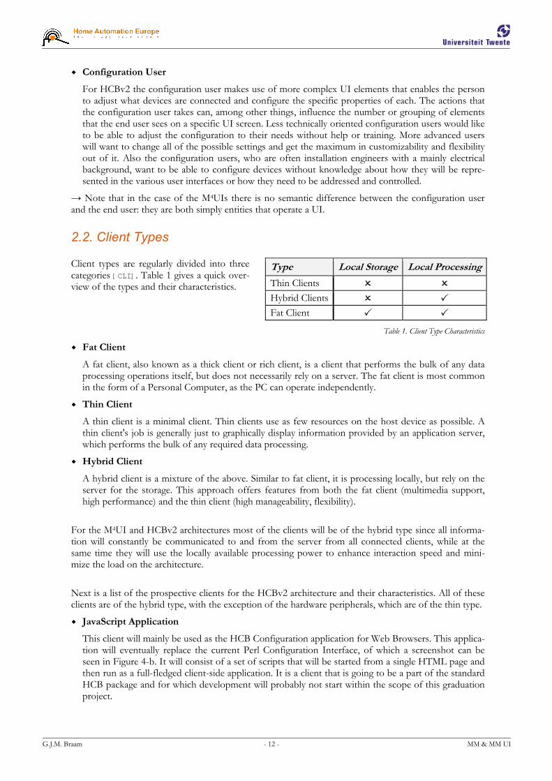
Client types are regularly divided into three categories [CLI]. Table 1 gives a quick over-view of the types and their characteristics.
Table 1. Client Type Characteristics
� Fat Client
A fat client, also known as a thick client or rich client, is a client that performs the bulk of any data processing operations itself, but does not necessarily rely on a server. The fat client is most common in the form of a Personal Computer, as the PC can operate independently.
� Thin Client
A thin client is a minimal client. Thin clients use as few resources on the host device as possible. A thin client's job is generally just to graphically display information provided by an application server, which performs the bulk of any required data processing.
� Hybrid Client
A hybrid client is a mixture of the above. Similar to fat client, it is processing locally, but rely on the server for the storage. This approach offers features from both the fat client (multimedia support, high performance) and the thin client (high manageability, flexibility).
For the M4UI and HCBv2 architectures most of the clients will be of the hybrid type since all informa-tion will constantly be communicated to and from the server from all connected clients, while at the same time they will use the locally available processing power to enhance interaction speed and mini-mize the load on the architecture.
Next is a list of the prospective clients for the HCBv2 architecture and their characteristics. All of these clients are of the hybrid type, with the exception of the hardware peripherals, which are of the thin type.
� JavaScript Application
This client will mainly be used as the HCB Configuration application for Web Browsers. This applica-tion will eventually replace the current Perl Configuration Interface, of which a screenshot can be seen in Figure 4-b. It will consist of a set of scripts that will be started from a single HTML page and then run as a full-fledged client-side application. It is a client that is going to be a part of the standard HCB package and for which development will probably not start within the scope of this graduation project.
Type Local Storage Local Processing
Thin Clients � � Hybrid Clients � �
Fat Client � �

G.J.M. Braam - 13 - MM & MM UI
Figure 2-b. Xanura DAIX10
It is however not unlikely that small, highly specific Java-Script control applets will be developed to be used as a part of the portal site that will run on the Service Center.
� Flash Application
For web-developers Macromedia Flash has become the standard for dynamic, graphically pleasing user interfaces and web pages. A lot of people are schooled in its use and it em-ploys a powerful embedded scripting language called Action-Script. Flash has excellent support for vector-based graphics and thus perfect for scaling to non-standard resolutions found on phones and PDAs. To the right in Figure 2-a is a screenshot of a demonstration interface developed at HAE as a result of an internship.
� Java Application
Java is a well-known language under developers and most software developers have worked with it at some point during their career. It has powerful network capabilities and comes in many flavors. As part of the Java Platform, Micro Edition (J2ME), the Mobile Information Device Profile (MIDP) is an API that is supported by most of the modern phones and PDAs on the market today. It offers functionality used in LCD User Interfaces and basic 2D gaming, perfect for developing a user-friendly and graphically pleasing interface. Programs written as MIDP MIDIlets can execute directly on many phones and PDAs.
Care should be taken that the user interface is useable on a wide range of different screen resolutions. MIDP includes API for communication with all the hardware that is present on the device it is exe-cuting on. Possible connection media thus include Infrared, Bluetooth, Wi-Fi, GPRS, UMTS, SMS and Email.
� Native Application
Software that executes natively on PDAs, SmartPhones and more complex remotes with a graphical user interface might be needed to support certain platforms. Development of this form of non-standard software will be avoided if possible, but if demand is high enough for a certain type of de-vice, it might be worth the investment. Both C and C++ offer fast and efficient code execution and, depending on the platform, powerful network facilities.
A lot of the internal code can be shared with applications to be developed for other platforms that fall under this category, which will make it easier to develop similar clients after the first one has paved the proverbial road.
� Hardware Peripherals
These clients will have minimal or no application and display logic. The largest part of the devices that connect to the HCB fall under this category and will be commercially available home automation components. They all support at least a one-way communication channel to the HCB, either as command provider or as a information receiver. An example of the first is a simple light switch that sends an event, an example of the second is a remote controlled lamp that can receive a command to turn itself on or off. These clients usually do not have a screen, some have a simple state that is visible, like a light that is on or off, or maybe a LED indicating that it is active.
An example of such a device can be seen in Figure 2-b. It is a Xanura DAIX10 dim actor and inter-face module which can be built into a wall socket. It can send commands from a physical dimmer and at the same time output a voltage according to dimming commands it receives.
Some of these clients and their development will be discussed further in §7.4 ‘User Interfaces’.
Figure 2-a. PocketPC Demo Flash Interface

G.J.M. Braam - 14 - MM & MM UI
2.3. Modalities
The concept of Multi-modality can be divided into two groups: ‘Sequential Multi-modality’ versus ‘Si-multaneous Multi-modality’ [RIN]. This division has impact on the complexity of the user’s utterances and they way that they are inter-connected.
In the sequential one a system that supports multi-modal input is restricted by some form of progress script that determines at what point in a user interaction exchange a certain modality is allowed. Imagine a phone call to a technical support helpdesk (maybe that of Packard Bell) in which you are first required to enter the serial number of the troublesome device in question by means of the number keys on your phone. Next, in order to verify your current address which is read aloud by a text-to-speech voice syn-thesis application, you need to speak either the word ‘Yes’ or ‘No’. After that you can navigate though an Interactive Voice Response system by means of your number keys again, and finally go make some tea while you wait for an actual helpdesk representative to talk to you. One input modality interaction is clearly scheduled after the other, and no overlap or interaction between them takes place.
The simultaneous one would be a system that allows free-form interaction by means of multiple input modalities in a non-determined order. An example of this case could be a fictive interactive digital city guide mounted inside a small booth located on one of the many the prominent city squares. This system asks what we are looking for and we say that “we want to go to a museum”. It shows the map, centered around the you-are-here marker with the nearest museums highlighted on it. While you tap on the screen to select a museum you ask “how much does this one cost for two people?” It replies with a price and the suggestion to make a reservation, because there is currently a long waiting line. You then say “please reserve place for two people at four o’clock” and insert your credit card. These input modalities are used at random times and can signify all kinds of decisions in the current session. The utterances in the different modalities need to be used together in order to understand what the command really is, a process also known as semantic fusion. This kind of interaction is much more complex to support, es-pecially if the environment is susceptible to noise or other non-intended inputs.
The M4UIs handled here are mostly sequentially multi-modal, by reasons of processing complexity. An embedded platform such as the HCB does not (yet) have the power to handle these complex interaction patterns, let alone be able to perform tasks like real-time speech recognition.
Recent market movements towards using more complex modalities in daily-use appliances, of which TomTom is the primary example for audio, are paving the road for other appliances with these modali-ties. Devices with hardware support for these capabilities built into them will probably be appearing in the near future, so support for these more complex modalities should certainly be taken into account.
2.4. M4UI Requirements
Given here are a set of general requirements for home control user interfaces that are multi-modal and multi-medial, as well as those for the underlying facilities the UIs need to perform their duties. The re-quirements that relate to the internal workings of the clients and the way that the architecture supports them are listed in the paragraph Data Transfer. Subsequently, requirements that pertain to the part that users will interact with are given in the paragraph User Interface.
→ In the following paragraphs the supporting base framework and specifically the part or parts that will be responsible for handling connections with clients will simply be referred to as ‘server’.
2.4.1. Data Transfer
The requirements listed here relate to data that is transferred to or from UIs. These requirements will help when designing the lower-level communication support services, the structure of the information that will be transported and be used for guidance during the implementation phase.
� Message Sending
The client needs to be able to send messages to the server. The term message is used in a very broad sense: it can contain anything from client-side dynamic interface elements to specific commands gen-erated by UI operations.

G.J.M. Braam - 15 - MM & MM UI
� Message Receiving by Server Push
For receiving messages there must be a minimal delay from the time that the event occurs on the server to the time that it is received by a client. This means that polling is not an option and a form of server push probably needs to be used.
� Reliable Message Delivery
Messages that are sent either to or from the client need to be reliable. It must not be possible for a message to get lost during regular communication.
� Long-time Connections
Some of these clients can be connected and remain idle for very long times. Issues like visible time-outs and the subsequent need to (manually) reconnect should be avoided. A good maximum is probably 120 hours, or five days, as is the specified period for established TCP/IP connections to stay connected without any data transfer.
� Location Independence
Clients need to be able to connect from virtually anywhere in the world. This usually makes one think about internet-based solutions, but message carriers like SMS and GSM modems could also apply here.
� Connection Medium Independence
Connections to clients should not be dependent on the connection medium they are sent over. This will enable the use of connection handovers in the future, for instance automatic switching from GRPS to the local WLAN when you get home from work without losing client connection and state information.
� Authentication & Authorization
Clients need to authenticate themselves to ascertain their identity on the server. Further some sort of a permissions or role system is needed to authorize recognized users before they can perform certain actions.
2.4.2. User Interface
The requirements shown here pertain to the client-side aspects of graphical UIs that perform a control task over one or more parts of a home.
� Intuitive & Easy to Use
The UI running on the clients for daily use needs to be intuitive and it should be possible to start us-ing them with minimal or no help.
� Consistent Look
A consistent look needs to be maintained over the different screens within clients, as well as over the different clients on different platforms. This will ensure that once a user can use one of the clients, they can use all of them and generally leads to a more pleasant user experience.
� Fast Interaction Response
During use of the interface the operations performed by the user must show that some action is be-ing taken by the client right away. This action may not depend on communication with the server first, since in some cases this could take too long. The actual command and confirmation delay, being a round-trip time, should be below two seconds to be usable from the user’s perspective.
� Transparent Internal State
A transparent internal state means that it must be clear to the user what is happening as a result of a non-fast action inside the client, at least to a certain level. This includes some sort of visible ‘process-ing...’ state when it is busy or waiting for a command confirmation from the server.

G.J.M. Braam - 16 - MM & MM UI
� Dynamic Element Support
Support needs to be present for dynamic UI elements, of which the contents are supplied by mes-sages. This includes adding and removing of elements at run-time.
� Element State Updates
Upon reception of a message with a new state for a control element, the visual state of that UI ele-ment must be updated to show this new state.
� Multi-media Elements
The UIs will have to be graphically pleasing with smart placement of text, images and possibly small audio effects to attract attention to events. In the future it could also be possible to send icons and other multi-media data to the clients for use as part of the UI.
� Useable on Touch Screens
It is necessary that the interfaces work with touch screens and also with regular screens that do not offer this modality. User interfaces with touch screens are preferred however, since they are the ones that are the fastest and easiest to use.
� Useable on Multiple Resolutions
There are a lot of different small resolutions used on PDAs & phones. The UIs need to be useable and the text readable on all but the tiniest screens.
� Complex Modalities
Support for the more standard modalities like keyboards, mice, buttons & touch screens for input and screens & audio for output are nothing special nowadays. Supporting the more complex modali-ties like speech recognition or gesture recognition will be important assets in the future.
These requirements will play a supporting role during the actual design of the UIs themselves, but some also rely on communication features given in the last Data Transfer paragraph like for instance sending multi-media content to be used as a UI elements for display or playback.
2.5. HCBv2 Requirements
Using the requirements for M4UI as a basis, this section lists the requirements specific to HCBv2, the new framework for the HCB hardware platform. All the requirements listed in the previous section automatically apply to HCBv2, with a number of specific UI-related extensions given in the paragraph User Interface.
The requirements regarding the other underlying features needed in the HCBv2 framework are de-scribed in the next paragraph, Functionality. The HCB will especially be interfacing with a large variety of Hardware, essentially the reason for its existence. The hardware part is divided into paragraphs on Connec-tion Media and on Devices.
2.5.1. User Interface
On top of the requirements specified for Generic M4UIs which also apply here, these add extra features that are only relevant to UIs used in combination with the HCB and its specific applications.
� User Complexity Levels
The UI needs to be able to display more and more complex settings to users that have a higher user complexity level. The different levels could for instance be User, Installer and Admin. This would mean that it would hide certain advanced settings for less technically inclined users. This requirement only applies to the Configuration UI, which is a lot more complex than the Daily Use UI.

G.J.M. Braam - 17 - MM & MM UI
� Sensor Device Support
The UI needs to be able to display values for devices that do not have a control aspect associated with them. In contrast to the controls that are needed for switching and dimming devices, these sen-sor device UI components only display a certain value like for instance a temperature or the value of a custom user variable.
� Device Categorization
The UI needs to be able to display devices in categories. Categorization can for instance be on the room, location or group that the device is in. Navigating between these categories needs to be fast & easy.
� Large Numbers of Categories/Devices
There must not be a certain maximum of categories or devices per category that can be displayed be-cause of for instance lack of screen real estate. The UI needs to be built to handle theoretically unlim-ited number of categories/devices, although I imagine scrolling through hundreds of categories could get tiresome after a while.
� Estimated Processing Times
Using estimated reaction times to display UI component “Processing…” states while sending a command over a known non-instantaneous connection medium could significantly improve the user experience. These time estimates could be sent along with the Home Layout message described under Message Protocol in the next paragraph. For instance, sending messages over X10 can take up to a full second to complete.
2.5.2. Functional
In this paragraph the general features required and used by practically all parts of HCBv2 are enumer-ated. Most of these features will probably be implemented in a shared library.
A complete list of these functional requirements is given here because at the time that these require-ments are being composed these features do not yet exist. Because the functionality that relates to user interfaces depends heavily on most of these features, their basic behavior needs to be explained here.
� Data Storage
A place is needed where volatile and persistent data on the current state and configuration of the HCB is stored. A lot of this data needs to be accessed from multiple applications and processes that will be running on the HCB. Access to this functionality needs to be easy, robust, fast and as flexible as possible because this is an elemental component of the HCB Core structure that will be used fre-quently. Data like configuration settings, device states and macro definitions will be stored here.
� Integrated Language Translation
Not all people that will be using the HCB will understand English at a sufficient level to perform ba-sic tasks. Support needs to be present to switch between multiple languages on the fly based on user preferences. This support needs to be tightly integrated into the system functions so a maximum of translation details are handled by the framework. The aim is to set up a system so that translation and parameter insertion (á la printf()) and basic mutations like uppercasing and lowercasing are handled automatically.
� Dynamic Scripting
Users and system integrators need to be able to set up specific scenarios, sometimes called scripted actions or macros, on their HCB. These macros can be programmed using the configuration user in-terface and are therefore very dynamic in nature. The initial Perl system, written in a scripting lan-guage itself, could support this natively. In the new C environment some kind of dynamic logic is needed to enable this kind of flexibility. The best way to go would probably be to embed an existing light-weight and interpreted language into the HCB Core system.

G.J.M. Braam - 18 - MM & MM UI
� Central Logging
Developers will need a central facility to log messages about the configuration and use of the HCB. Because of the limited nature of the embedded platform care should also be taken to make sure that the available disk resources are used efficiently. Logging will be in a number of main categories, have a certain priority, be cached to minimize writes to the slow flash file system and be reliably transferred to the Service Center for processing & space preservation. The API will include functions with printf()-like arguments to facilitate parameter insertion in the log strings.
� Security
Simple basic security features will be implemented in the first software version, full AAA (Authenti-cation, Authorization, Accounting) will be implemented in later versions. All local access to the HCB via LAN and WLAN are assumed to be safe: it is the responsibility of the end-user to secure their lo-cal network. External access from the internet is always routed through the Service Center so security can therefore be handled there. Care should be taken to allow for possible future 3rd party modules to be running on the platform with restricted rights.
� Asynchronous Event Handling
The initial Perl implementation uses a synchronous polling model to check for new events and sce-narios. The new model needs to be event-driven and flexible enough to support communication of configuration settings, commands sent from/to devices and status updates sent to clients. Some sort of subscription system is needed to internally keep track of connected devices and clients.
� Message Protocol
To communicate all commands and logistic messages inside and outside the HCB a separate message protocol is needed. All of the features listed in §2.4.1 ‘Data Transfer’ apply to this protocol. It needs to be set up so it can also service all the types of internal and external UI clients in a transparent and uniform way. The functionality as described will be used for local and remote connections with the HCB so the protocol to be designed should be flexible and efficient with respect to usage, speed and bandwidth.
To be clear about when we refer to this protocol it has been dubbed BoxTalk without having a com-plete specification at this time. The following types of messages have been identified:
� General Device/Service Discovery
Devices, as well as the services provided by them, need to be announced to the system when they become available. Conversely a message is needed to announce the removal of a device and/or its services.
� General State Variable Subscribe/unsubscribe
The possibility to subscribe to specific state variables, thereby receiving asynchronous updates when changes to this state variable occur. A way to unsubscribe is subsequently also needed.
� General State Variable Updates
The state variables to which a client is subscribed need a way to be communicated. The device de-livering the service can send these messages to its subscribers to let them know a variable has changed.
� General Action Request/Response
The ability to do some sort of remote function call by sending a request accompanied by possible parameters. The response is always received asynchronously to minimize pieces of the code that are blocked while waiting for a response.
� Dynamic Room / Device Layout
A way is needed to retrieve an initial home layout so clients know what devices to display for each room. This can probably be done using an Action Request. Then, for later changes to the home layout, a subscription to these changes which possibly triggers a new initial request, or maybe even a specific device addition message.

G.J.M. Braam - 19 - MM & MM UI
� Synchronized (Device) States
The interfaces on all clients would incorporate near-real-time synchronized, possibly multi-dimensional states on all modalities for all devices. The Subscriptions and Variable Updates can fill this need.
� Device Commands
The ability to send specific commands to a unique device or to a group of them is needed. This can be achieved by using Action Request messages. A command can carry possible arguments, which is supported by the Action Request message above.
� Connection Media and Device Response Times
The response times for used connection media and for specific devices should be communicated to clients for appropriate use of sync-delay and the use of sending/busy UI elements. Even some of the wired connection media, like for instance A10/X10, can take up to one second for a com-mand to be transferred. This information could possibly be sent as extra data with a Home Layout message.
2.5.3. Hardware
The hardware requirements consist of an inventory of existing and near-future technologies that the HCB could and most likely will work with. Support for the different technologies will be added incre-mentally, depending on the development roadmap, general standards acceptation and hardware device availability. Directly below in Figure 2-c is a copy of the diagram as shown in the introduction. It shows how the different devices connect to the HCB using the different media.
Figure 2-c. Connection Media and Devices in relation to the HCB
→ Please note the figure is repeated here to avoid unnecessary page flipping.
This section is divided into two parts: Connection Media and Devices. First I will list the possible connection media, then I will look at some more generally used devices and their applicability in controlling the HCB.

G.J.M. Braam - 20 - MM & MM UI
2.5.3.1. Connection Media
The different connection media are grouped in a number of categories:
� TCP/IP-based (Ethernet LAN, WLAN, GPRS/UMTS)
� Local Connectivity (Infrared, Bluetooth, DECT)
� Simple Command Protocols (DTMF, SMS, Email)
� Home Automation Standards (A10/X10, Konnex, Zigbee, Visonic, Honeywell)
In the future support might be added for connection media handovers. This would for example enable some clients to automatically switch from GRPS to the local WLAN when they get home from work without losing connection and state information. This means that a number of measures need to be taken when designing the communication protocol, sessions and with respect to client addressing and tracking. Also note that not all of the listed media are suitable for this kind of handover.
An overview of the evaluated media is given in Table 2 ‘Connection Media Features’:
Type Range Wired Directional Way Latency Category
Ethernet LAN Home � Omni Two Minimal
WLAN Home � Omni Two Minimal
GPRS/UMTS World � Omni Two Medium
TCP/IP based
Infrared Room � Directional One Minimal
Bluetooth Room � Omni Two Minimal
DECT Home � Omni Two Minimal
Local Connectivity
DTMF World � Omni Two Minimal
SMS World � Omni Two Medium
E-mail World � Omni Two High
Simple Command Protocols
A10/X10 Home Both Omni Two Medium
Konnex Home � Omni Two Minimal
Zigbee Home � Omni Two Minimal
Visonic Home � Omni One Minimal
Honeywell Home � Omni Two Minimal
Home Automation Standards
Table 2. Connection Media Features
The complete and unabbreviated list is given in Appendix IV ‘HCB Hardware Requirements’ under the heading ‘Connection Media’.

G.J.M. Braam - 21 - MM & MM UI
2.5.3.2. Devices
The word devices is taken very general here. Under devices I will assume all types of hard- and software that have some sort of user interface and can send and/or receive information when connected to the HCB. Bear in mind this is just an inventory of possible devices that could be used with the HCB, it is not meant to be complete or exhaustive. A quick overview of the discussed devices is given in Table 3.
Type Client State Communication Screen
Regular PC Web Browser Complex TCP/IP-based Normal
Touch Screen PC Browser / Flash / Java Complex TCP/IP-based Normal
PocketPC Flash / Java Complex WLAN, BT Small
PalmOS Flash / Native Complex WLAN, BT Small
DTMF Phones Server-side Menu Simple Phone Line No
DECT Phones Server-side Menu Simple DECT No
SymbianOS Phones Flash / Java / Native Complex WLAN, BT, IR Small
Regular Remote Controls Server-side Menu No IR, RF No
Game Consoles Flash / Native Complex TCP/IP-based TV
Portable Game Consoles Flash / Native Complex TCP/IP-based Small
Home Automation Components Hardware No Power Line, RF No
Other Hardware Hardware No Power Line, RF No
Set-Top Box Web Browser Complex TCP/IP-based TV
Table 3. Device Features
Again, the complete and unabbreviated list is discussed in further detail in Appendix IV ‘HCB Hardware Requirements’ under the heading ‘Devices’.
2.6. Summary
The design overview given in this chapter reviews aspects like user types, client types and modalities, all of which are relevant to the composition of the requirements. Describing the user types also provides an answers to the research question about the types of users of the system and their specific needs.
The requirements listed for the M4UI and HCBv2 architectures provide a good reference when compos-ing the design specifications and help to keep developers focused on important features during evalua-tion of possible open source solutions and the implementation phase of custom software.
The description of home automation specific hardware in the form of connection media and devices supplies the reader with a general idea of these technologies and makes understanding the references to them from the rest of this document a lot easier. It also helps paint a picture of the environment that the HCB, as a universal systems integration tool, is operating in.
The requirements listed in this chapter will be combined to specify two separate architectures. These architectures are described in the next two chapters.

G.J.M. Braam - 22 - MM & MM UI
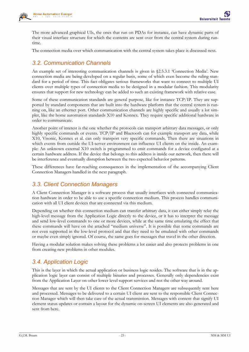
3. M4UI Structure Design
This chapter presents a layout for a generic structure for M4UIs, in which an overview of the most basic components needed in a M4UI client-server architecture is given. It also provides information towards answering the “What demands does this system have with respect to data communication to and from the UIs?” question. Discussing this here provides an opportunity to only look at the M4UI-related fea-tures and communication properties of such a framework, without being distracted by the numerous other details and features that frameworks of this kind are justly equipped with.
A generic structure for building frameworks to sup-port M4UIs can be broken down into four major lay-ers, as shown in Figure 3-a:
In short, the UI clients, all very different devices with different communication capabilities, want to be able to exchange information with the Application Logic layer. Because of the diversity in communication channels, separate Client Connection Managers are created, one for each type of connection medium. They maintain the connections with the UI clients, relaying and translating messages back and forth, while they themselves are all directly connected to the Application Logic Layer.
→ Because of their limitations, the home automation standards X10 and Konnex are frequently being used as an example in the next paragraphs. This however does not mean that the following is only applicable to the field of home automation.
The four layers are described next, from the top down.
3.1. User Interface Clients
The UI clients range from regular web browsers to PDAs to light switches mounted on a wall. Any de-vice that has some form of output to show a user a state change (actor) or any device that can accept some form of input (sensor) can be a UI client. These devices would of course be in some way con-nected to a central system and be able to send messages, receive messages, or both.
Technically, a UI consists of a device with both in- and output capabilities, but for the sake of simplicity we will also refer to devices with only one of these capabilities as UI clients. Sometimes a combination of these devices form a bigger composite UI, like in the case where you flip a wall-mounted switch (sen-sor), some internal communication takes place, and a light goes on (actor).
These clients can support various in- and output modalities. We are especially interested in UIs that have a graphical way to display their state, like on a pixel-based screen, since they can convey a much more complex state to a user than for instance a single LED can. Some of these clients also support other out-put modalities like audio or vibration.
Input modalities include physical operation (like flipping a switch or turning a dimmer dial), device but-tons, mini joysticks, mice, keyboards and of course touch screens, which are most preferred, especially in combination with a small screen. More complex input modalities also include technologies like speech recognition and computer vision, but they are currently not yet relevant in embedded environments be-cause of processing power limitations.
TCP/IP
Bluetooth
Zigbee
Protocol ‘X’
Figure 3-a. M4UI General System Architecture
G.J.M. Braam - 23 - MM & MM UI
The more advanced graphical UIs, the ones that run on PDAs for instance, can have dynamic parts of their visual interface structure for which the contents are sent over from the central system during run-time.
The connection media over which communication with the central system takes place is discussed next.
3.2. Communication Channels
An example set of interesting communication channels is given in §2.5.3.1 ‘Connection Media’. New connection media are being developed on a regular basis, some of which even become the ruling stan-dard for a period of time. This fact obligates serious frameworks that want to connect to multiple UI clients over multiple types of connection media to be designed in a modular fashion. This modularity ensures that support for new technology can be added to such an existing framework with relative ease.
Some of these communication standards are general purpose, like for instance TCP/IP. They are sup-ported by standard components that are built into the hardware platform that the central system is run-ning on, like an ethernet port. Other communication channels are highly specific and usually a lot sim-pler, like the home automation standards X10 and Konnex. They require specific additional hardware in order to communicate.
Another point of interest is the one whether the protocols can transport arbitrary data messages, or only highly specific commands or events. TCP/IP and Bluetooth can for example transport any data, while X10, Visonic, Konnex et al. can only transport very specific commands. Then there are situations in which events from outside the UI-server environment can influence UI clients on the inside. An exam-ple: An unknown external X10 switch is programmed to emit commands for a device configured at a certain hardware address. If the device that belongs to this address is inside our network, then there will be interference and eventually disruption between the two expected behavior patterns.
These differences have far-reaching consequences in the implementation of the accompanying Client Connection Managers handled in the next paragraph.
3.3. Client Connection Managers
A Client Connection Manager is a software process that usually interfaces with connected communica-tion hardware in order to be able to use a specific connection medium. This process handles communi-cation with all UI client devices that are connected via this medium.
Depending on whether this connection medium can transfer arbitrary data, it can either simply relay the high-level message from the Application Logic directly to the device, or it has to interpret the message and send low-level commands to one or more devices, while at the same time emulating the effect that these commands will have on the attached “medium universe”. It is possible that some commands are not even supported in the low-level protocol and that they need to be emulated with other commands or maybe even simply ignored. Of course, the same goes for messages that travel in the other direction.
Having a modular solution makes solving these problems a lot easier and also protects problems in one from creating new problems in other modules.
3.4. Application Logic
This is the layer in which the actual application or business logic resides. The software that is in the ap-plication logic layer can consist of multiple binaries and processes. Generally only dependencies exist from the Application Layer on other lower level support services and not the other way around.
Messages that are sent by the UI clients to the Client Connection Managers are subsequently sent here and processed. Messages to be delivered to a certain UI client are sent to the responsible Client Connec-tion Manager which will then take care of the actual transmission. Messages with content that signify UI element status updates or contain a layout for the dynamic on-screen UI elements are also generated and sent from here.

G.J.M. Braam - 24 - MM & MM UI
The Application Logic needs to contain a central entity that keeps track of all of the connected UI cli-ents and which Client Connection Manager or Managers currently have an active connection to those UI clients. The state, be it client-side or server-side, should not rely on data stored at the Connection Managers, so multiple connections, and with it connection handovers, are made possible.
3.5. Summary
This chapter has shown that a clear separation is possible between the parts of a framework that directly communicate with connected UI clients and the parts that are responsible for the Application Logic. A modular design for these Client Connection Managers will make the addition of support for selective current and future communication technologies relatively easy. The problems and complexity associated with a certain connection medium are nicely encapsulated within its own module.
After a clear view of the communication aspects of a generic M4UI framework, we can now look at the design for the new and relatively much more complex HCBv2 framework in the next chapter.
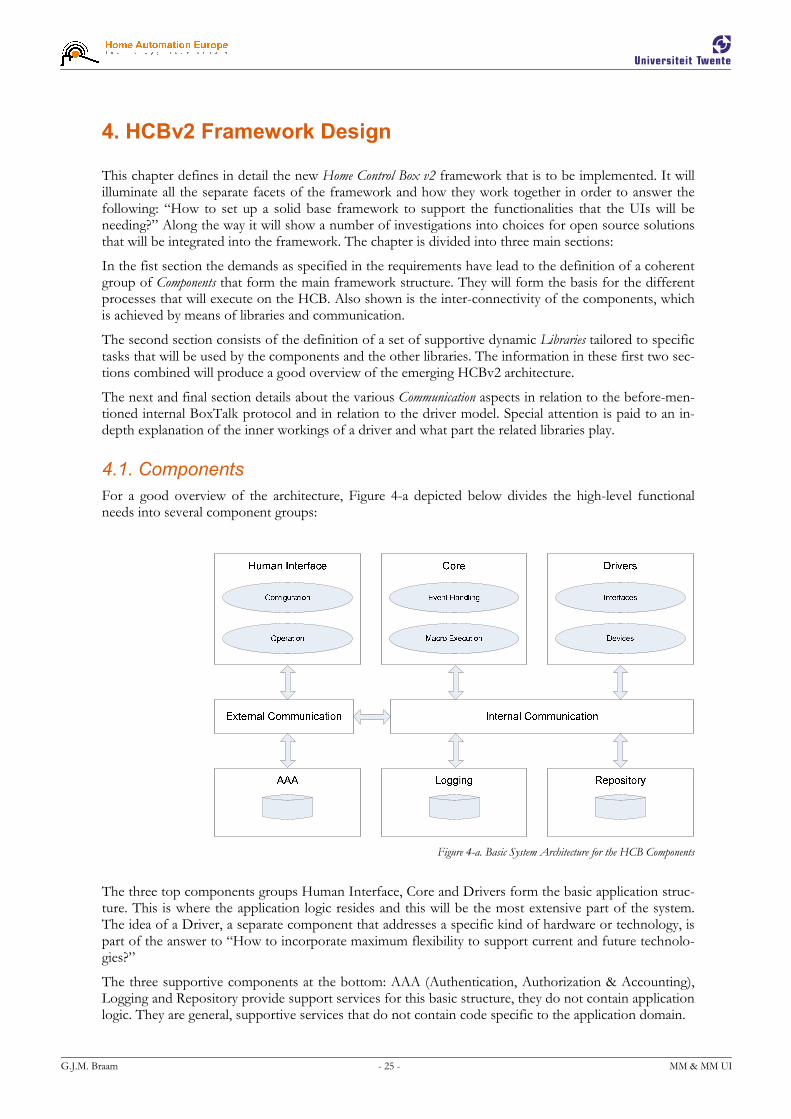
G.J.M. Braam - 25 - MM & MM UI
4. HCBv2 Framework Design
This chapter defines in detail the new Home Control Box v2 framework that is to be implemented. It will illuminate all the separate facets of the framework and how they work together in order to answer the following: “How to set up a solid base framework to support the functionalities that the UIs will be needing?” Along the way it will show a number of investigations into choices for open source solutions that will be integrated into the framework. The chapter is divided into three main sections:
In the fist section the demands as specified in the requirements have lead to the definition of a coherent group of Components that form the main framework structure. They will form the basis for the different processes that will execute on the HCB. Also shown is the inter-connectivity of the components, which is achieved by means of libraries and communication.
The second section consists of the definition of a set of supportive dynamic Libraries tailored to specific tasks that will be used by the components and the other libraries. The information in these first two sec-tions combined will produce a good overview of the emerging HCBv2 architecture.
The next and final section details about the various Communication aspects in relation to the before-men-tioned internal BoxTalk protocol and in relation to the driver model. Special attention is paid to an in-depth explanation of the inner workings of a driver and what part the related libraries play.
4.1. Components
For a good overview of the architecture, Figure 4-a depicted below divides the high-level functional needs into several component groups:
Figure 4-a. Basic System Architecture for the HCB Components
The three top components groups Human Interface, Core and Drivers form the basic application struc-ture. This is where the application logic resides and this will be the most extensive part of the system. The idea of a Driver, a separate component that addresses a specific kind of hardware or technology, is part of the answer to “How to incorporate maximum flexibility to support current and future technolo-gies?”
The three supportive components at the bottom: AAA (Authentication, Authorization & Accounting), Logging and Repository provide support services for this basic structure, they do not contain application logic. They are general, supportive services that do not contain code specific to the application domain.

G.J.M. Braam - 26 - MM & MM UI
All components communicate through the Internal and External communication components by means of BoxTalk messages. Each component sets up a separate connection with a central communication process, as will be described further down in section 4.3.2 ‘Communication Controller’.
4.1.1. Compared to M4UI Layers
→ To increase the readability of this paragraph, the many references to entities in previous paragraphs are shown in italics, a custom that is not repeated in the rest of this document.
When compared to the generic M4UI structure given in chapter 3, we can classify the relevant compo-nents here into the layers described there. For the Human Interface group these are clearly equivalent to the UI Clients in the top-most level.
The Core is of course the main place where the Application Logic resides, although some of this logic is also placed in the Human Interface and Driver components. The Configuration & Application clients and the Drivers certainly do contain considerate amounts of logic specific to the application domain.
The Drivers are evidently analogous to the Client Connection Managers, although the concept of a Driver de-scribed in more detail later on is much wider than just software that controls hardware for communica-tion purposes. Purely based on Figure 4-a however, a Driver and a Client Connection Manager are a perfect match.
The External Communication group here should in fact also include the Connection Media that the drivers interface with, only then is it fully enclosed by the Communication Channels from chapter 3. Also, in this sense Drivers are actually connected to both Internal and External Communication channels: internal for BoxTalk message exchange, external for communication by using their own specific protocols.
4.1.2. Human Interface
The component group Human Interface contains the components that directly interact with the users. These UI clients can be divided into two groups: those used for Configuration and the ones used for Op-eration.
The Configuration interface will be used by people that want to change some of the underlying proper-ties of the system. This will in practice be only a small percentage of the entire usage of the UIs, and will most likely primarily take place when the system is first installed. An example of such an interface is the HCB Configuration Screen depicted in Figure 4-b below.
Figure 4-b. The Home Control Box configuration screen of the legacy Perl Application
The other UI client group is the one that contains Operation clients. These UI clients only perform simple tasks when compared to the functionality and complexity that the configuration interfaces hold. Examples are the use of a PDA to turn off a light in the living room, an interface already shown in Figure 2-a, and the more traditional ways of interaction like flipping a wall-mounted switch to turn off

G.J.M. Braam - 27 - MM & MM UI
the same light. This switch is connected to or part of a home automation component like the Xanura DAIX10 in Figure 2-b that sends this command to the HCB. The event is exactly the same in the eyes of the application logic, except now this input event can also be used as a logical condition in a previ-ously composed scenario now primarily limited by the imagination.
The modalities used for output towards a user are limited by what devices are available on the market today and by the processing power the combined devices possess. Phones, PDAs and sophisticated re-mote controls are capable of visual and audio output, with sometimes even vibration. Home automation devices like dimming and switching actors can also be used for output: as long as they can change the state of a device in a way that is perceivable by a user.
Input modalities are also limited by commercial availability, the creation of suitable software and con-nection media coverage. For devices capable of displaying the graphical UIs these usually include a combination of buttons on the device, a 2D tactile interface (touch screen) or some sort of a mini joy-stick to manipulate an on-screen cursor. Embedded devices generally do not have enough processing power to be able to do speech recognition or any form of image processing. I have however heard ru-mors at HAE concerning a possible project that plans to perform speech recognition partly in hardware in the form of a specially designed chip. Another input modality, one that is already supported by the related modem hardware on the HCB, is the decoding of DTMF tones sent via a regular phone line.
These two UI client groups can be served by the same set of supportive services in HCBv2 because they rely on the same underlying Data Transfer features to be supported. Features like message sending, server push message reception, sending of home layout messages Data Transfer and 24/7 connectivity solutions are provided by the framework.
Devices of all the client types discussed in §2.2 will be able to connect to the HCB over multiple con-nection media. The most frequently used medium will probably be TCP/IP over one of the two built in ethernet adapters. The TCP/IP client connections, which will communicate by means of BoxTalk mes-sages, will be handled by special extensions built into a small web server which is further discussed
in §4.1.6 ‘External Communication’.
4.1.3. Core
The HCB Core deals with all the intelligent handling of BoxTalk messages. It is subscribed to receive all messages so it can keep track of all events that happen in and around the HCB.
The Core also handles execution of macros written in a dynamic scripting language and manages user timers and variables. It will determine when to execute macros based on conditions. These conditional sections of the macros can depend on a large number of triggers like device actions, relative & absolute dates & times, specific values for variables or timers. Also states of devices or the changes of these states can serve as a trigger for macro execution.
The then executed macros can generate BoxTalk commands for the configured actor devices (turning on a lamp), built-in actions (turning off LED #4 on the HCB) and Service Center functionality (sending an SMS message to a user). In a macro you can also manipulate user variables and timers, thereby influ-encing the execution of other macros which in turn enables the construction of more complex systems that behave somewhat like state machines.
The language that will be used for the macros as well as the reasons for this choice are described in §4.2.3 ‘Scripting Language’.
The Core is also responsible for managing the entire HCB Configuration, consisting of general settings, devices, rooms, groups, macros, timers, variables and their respective customizations. All changes to the configuration by a client-side configuration application are sent to the core and processed. Also Home Layout messages specifying a list of rooms and the devices they contain are generated here to be sent to external M4UI operation clients.

G.J.M. Braam - 28 - MM & MM UI
4.1.4. Drivers
Drivers are a very important part of the HCB. Their flexibility and the ease with which they can be de-veloped are imperative to the commercial success of the HCB. The HCB presents itself as an integration platform to combine multiple home automation technologies that are normally incompatible with each other. The support of a protocol that has already been standardized or the support of a very new and not yet common technology must be easy to add and with a minimum of development time.
A driver creates a link between two sides, the BoxTalk Interface and the Device Hardware Interface:
� BoxTalk Interface
The BoxTalk Interface is the side that receives and sends messages in the internal BoxTalk format. All internal non-hardware communication with the driver is handled through BoxTalk messages. This side uses functions from a library to receive, parse the XML and get information from the incoming BoxTalk messages. Also library functions are being used to create BoxTalk messages and set various parameters in them before they are sent.
� Hardware Devices
The other side is the side that interfaces with specific hardware that is present inside or connected to the HCB. This part has its own polling loop or preferably interrupt-based handling, and can send BoxTalk messages when appropriate events occur. Examples of these are the drivers currently under development for the home automation standards A10/X10, Konnex and Zigbee.
A driver process is managed by a special library that is linked to each driver. This library basically con-trols how the driver executable is initialized, starts the autonomous part, automatically handles the more platform-generic incoming BoxTalk messages and finally how the driver itself is terminated. More on the BoxTalk Driver model and how a driver functions exactly can be found in §4.3.3 ‘Driver Model’ below.
4.1.5. Internal Communication
All internal communication is handled centrally by a process dubbed the Communication Controller. A central approach was chosen over a distributed approach for a number of reasons:
� a single point of entry, so there is no discovery overhead;
� the least amount of communication channels, just one per driver;
� all routing logic is handled in one place;
� easy logging and debugging of all messages that are sent;
� clear separation between internal and external communication.
The resulting central approach clearly provides the most efficient solution. A strong reason to go for a distributed approach would be the inherent robustness, but this reason does not weigh up to the ones in favor of the central approach. However, to heighten the robustness, measures are being taken to make sure that the drivers are able to reconnect to the Communication Controller without problems and that all connected processes end up in the same state as before.
The Communication Controller serves as a central hub that takes care of all internal BoxTalk communi-cations. All Drivers associate themselves with the Communication Controller when they start up. All BoxTalk messages are sent to this process, which in turn routes them to the correct destination device or devices. All routing and addressing functionality is placed in the Communication Controller, the driver processes are relatively simple, relying on the Communication Controller to deliver their BoxTalk messages. Each device can subscribe itself to services of other devices, thereby receiving BoxTalk 'no-tify' messages afterwards. To incorporate a certain amount of robustness, all drivers and even the Com-munication Controller will be able to be restarted and reconnect without problems.
The actual internal communication method is further explained in §4.3.1 ‘Inter-Process Communica-tion’. This component and its responsibilities with respect to drivers and message routing are further explained in §4.3.2 ‘Communication Controller’ below.
G.J.M. Braam - 29 - MM & MM UI
4.1.6. External Communication
External Communication is not really a component, but more a logical grouping of processes that per-form IP-based communication with the following external entities:
� Web Browsers / BoxTalk Clients
Communication is initiated via port 80, using the HTTP protocol. Clients can also send BoxTalk messages by sending a special POST request to the webserver. Reply BoxTalk messages are received as the content of the returned document.
This small webserver will multiplex these two kinds of connections on port 80, the standard port used for web traffic. Besides the normal HTTP connections, the clients will also be able to communi-cate with BoxTalk messages over this port. Client-side communication mechanisms like for instance JavaScript’s xmlHttpRequest() object sometimes have security restrictions requiring them to only connect to the same host and port from which the web pages were served, therefore requiring the multiplexing.
When approached as a regular webserver it can serve a user interface by delivering regular HTML documents with CSS, images and JavaScript. When approached as a server for BoxTalk messages it will keep a list of connected clients and route these messages to and from a central communication process. It also makes sure that the connected clients receive the necessary status update messages to ensure that their interfaces are able to display a real-time status view of the devices that are connected to the HCB.
In the case of webpage-based clients the application logic resides partly in JavaScript and partly in the core, where all configuration modifications are handled. The webserver will only serve static content, the Graphical User Interface will execute entirely on the client-side with JavaScript and by exchanging BoxTalk messages with the HCB.
� Service Center
All communication to the Service Center uses the secure Virtual Private Network [VPN] tunnel which is automatically established when the HCB starts up. All features that will be delivered by the Service Center, either initiated by the HCB (like sending an e-mail message) or initiated by a service on the Service Center side (like receiving an e-mail message), will be private and secure. Users will also be able to control their HCB from anywhere on the internet by using a portal site also running at the Service Center. The internal workings and responsibilities of the Service Center are outside the scope of this document.
� UPnP Devices
UPnP, or Universal Plug and Play [UPP], is a standardized collection of protocols that allows devices connected to the same LAN to configure themselves, find each other, see what services they have to offer and finally also use these services. In time the HCB will be able to announce itself via UPnP as a hub device representing all the connected devices, most of which do not or inherently cannot have a UPnP interface. An example HCB could for instance offer control of 20 lights, 12 light switches, 2 curtain controllers and 3 motion sensors. The HCB can then be used as a powerful component pro-viding UPnP-capabilities for all kinds of devices that normally do not support this. UPnP features will most likely be added in a later version of the HCB software, since it is a non-essential component.
Each type of communication is handled by a separate process, as will be explained in §7.1 ‘Binaries’.
4.1.7. Supportive Services
AAA
Authentication, Authorization & Accounting (AAA) consists of three separate parts, like the name sug-gests. Authentication will deal with user accounts and passwords, to ascertain that people are who they say they are. Then Authorization provides a way to enforce certain permissions for users or groups of users and deny actions for which they have no permission. Finally Accounting will keep track of actions that have been allowed or denied, probably by relying on the Logging facility.

G.J.M. Braam - 30 - MM & MM UI
These features will be delivered as a service with its own API, so other services can incorporate it in their own code to secure access to specific functionality. Full Authentication, Authorization & Account-ing will not be present in the first version of the framework, its future incorporation into the framework will however be taken into account during implementation.
Logging
The Logging process receives specific log actions via BoxTalk and logs various other BoxTalk messages to which it subscribes on startup. Messages can be logged in several different categories and have a pri-ority associated with them. Currently there are four possible priorities: Notice, Warning, Error & Criti-cal. Also messages can have certain flags for features like 'Flush to Disk', 'SMS', 'Email' and 'Store Only Locally' (do not send to Service Center). Finally all log messages have an associated TTL, a Time To Live value, allowing the log process to remove specific messages after they have expired in case the logs are starting to use up too much disk space. This process needs to perform autonomous tasks and needs to be available from other processes, so part of the implementation will be in the form of a BoxTalk Driver Executable and part will be in library form, included in the ‘Base Utility Functions’ in §4.2.1.
Repository
For storing volatile data that needs to be accessed from multiple processes quickly and reliably some sort of database system is needed.
This database system needs to be fast, accessible simultaneously from multiple processes, provide some form of crash recovery to insure data consistency and have a small memory and processor footprint. Also a full-weight SQL implementation is probably not necessary, since it will be used in an embedded setting, so tight integration by means of direct API functions is preferred. Another issue is the context-switch delay that is introduced if communication with the database also spans across processes.
The following list of software has been reviewed and in most cases compiled for and tested on the HCB:
Software License Lang Format TransAct Recovery In-memory
MiniDB GPL C Library � � No
SQLite Public Domain C Library � � Possible
MySQL GPL C Executable � � Caching
mSQL Commercial C Executable � � Caching
Berkeley DB GPL C Library � � Caching
KekeDB GPL C Library � � No
MonetDB MPL C Executable � � Caching
FastDB Public Domain C++ Library � � 100%
GigaBASE Public Domain C++ Library � � Caching
Table 4. Investigated database management systems
� MiniDB (License: GPL, http://www.atbas.org/minidb/)
MiniDB has a very minimal feature set, as well as using an ASCII-based file format. It is a disk-only system, has no crash-recovery and has minimal concurrency support. Also it has no SQL-like inter-face. Disk-based systems are not an option because of high flash disk file access times on the HCB.
� SQLite (License: Public Domain, http://www.sqlite.org/)
SQLite is a small C library that implements a self-contained, embeddable, zero-configuration SQL da-tabase engine. Because an SQLite database requires little or no administration, SQLite is a good choice for devices or services that must work unattended and without human support. SQLite is a good fit for use in cell phones, PDAs, set-top boxes, and/or appliances. It also works well as an em-bedded database in downloadable consumer applications.

G.J.M. Braam - 31 - MM & MM UI
� MySQL (License: GPL, http://www.mysql.com/)
The most popular open source database system on the web these days. It has all the required features and more but it is a far too heavy for an embedded environment. It has been tested in combination with Apache and PHP on the HCB: it works well, albeit too slow for our purposes.
� mSQL (License: Commercial, http://www.hughes.com.au/products/msql/)
Mini SQL is a light-weight SQL Database engine technology. It can run as a single threaded daemon or as a multi threaded process using a thread pool. It has a commercial license, making it less interest-ing because there is an abundance of free, open source solutions available.
� Berkeley DB (License: GPL, http://www.sleepycat.com/products/bdb.html)
Berkeley DB is a high-performance, embedded database library with bindings in C, C++, Java, Perl, Python, Tcl and many other programming languages. BDB stores arbitrary key/data pairs, and sup-ports multiple data items for a single key. BDB can support thousands of simultaneous threads of control manipulating databases as large as 256 terabytes, on a wide variety of systems including most UNIX-like and Windows systems as well as real-time operating systems.
� KekeDB (License: GPL, http://sourceforge.net/projects/kekedb/)
A light-weighted database server for embedded linux systems. Provides b-trees, network access and an SQL-styled query language. Its main goals are to be as tiny as possible with minimal set of features. It is based on Berkeley’s libdb1 to provide a reliable backend for saving data to disk. Tables have lit-tle structure: fields are referenced by number, not as usual by name. Also this is a solution that is based on DBD, another solution under review, thus introducing an unnecessary extra level and the accompanying inefficiency.
� MonetDB (License: MPL, http://monetdb.cwi.nl/)
MonetDB is an open source high-performance database system developed at CWI, the Institute for Mathematics and Computer Science Research of The Netherlands. It was designed to provide high performance on complex queries against large databases, e.g. combining tables with hundreds of col-umns and multi-million rows. As such, MonetDB can be used in application areas that because of performance issues are no-go areas for using traditional database technology in a real-time manner. MonetDB has been successfully applied in high-performance applications for data mining, OLAP, GIS, XML Query, text and multimedia retrieval.
� FastDB (License: Public Domain, http://www.garret.ru/~knizhnik/fastdb.html)
FastDB is a highly efficient main memory database system with real-time capabilities and convenient C++ interface. FastDB doesn't support a client-server architecture and all applications using a FastDB database should run at the same host. High speed of query execution is provided by the elimination of data transfer overhead and a very effective locking implementation. The Database file is mapped to the virtual memory space of each application working with the database. So the query is executed in the context of the application, requiring no context switching and inter-process data transfer. Synchronization of concurrent database access is implemented in FastDB by means of atomic in-structions, adding almost no overhead to query processing. In FastDB ensures that the whole data-base is present in RAM and optimizes the search algorithms and structures according to this assump-tion.

G.J.M. Braam - 32 - MM & MM UI
� GigaBASE (License: Public Domain, http://www.garret.ru/~knizhnik/gigabase.html)
GigaBASE is an object-relational database system with the same programming interface as FastDB main memory DBMS, but using a page pool instead of mapping database file to the memory. That is why GigaBASE is able to handle databases which size exceeds size of computers virtual memory. Like FastDB, GigaBASE provides a very convenient and efficient C++ interface. GigaBASE doesn't support a client-server architecture and provides concurrent access to the database only for different threads within one process. GigaBASE is most efficient for applications fetching records using indi-ces or direct object references. High speed of query execution is provided by elimination of data transfer overhead and very effective locking implementation. Synchronization of concurrent database access is implemented in GigaBASE by means of atomic instructions, adding almost no overhead to query processing. GigaBASE uses modified B-tree indices to provide fast access to disk resident data with minimal disk read operations.
After reviewing the features of each of the different database management systems and the requirements for this component, all but SQLite, Berkeley DB and FastDB already disqualify based on the criteria given above. These three database systems have been tested for speed in a small benchmark of which the results are presented in Table 5 below. For each system 3000 queries have been run: accesses doing 1000 writes, reads & deletes respectively. All times are total test program execution in milliseconds.
Database Version Library size (kB) Run 1 Run 2 Run 3 Average (ms)
SQLite 3.3.3 346.900 1026 974 1003 1001
Berkeley DB 4.4.20 791.476 754 801 734 763
FastDB 3.23 346.180 761 698 752 737
Table 5. Database Systems benchmarks run on the HCB
FastDB proves the fastest, but closely followed by Berkeley DB. FastDB thus stands out as the best overall option, not in the least because of the fact that 100% of the database is always kept in shared memory [SHA] and that it can be accessed from within multiple calling processes without requiring inter-process communication and with it costly context switching. Should any of the data-accessing applica-tions fail, then no data is lost. The library has built-in automatic crash-recovery support and will be ex-tended with periodic disk synchronization support. I minor disadvantage is the fact that FastDB itself is written in C++, and the rest of HCBv2 in C, which will need some extra wrapping code in the library API. This library can now be used by applications, drivers and other libraries to store persistent data easily and securely.
Watchdog
The watchdog process is a relatively simple and robust application that checks that the Server Processes specified in its configuration file are up and are responsive to messages. The process itself should be as simple as possible, to be sure that no bugs are present because this component manages the availability of all the other HCB Core components. On startup it reads a configuration XML file with the processes that need to be up & running. It will then try to start these processes in the configured order. Next it periodically checks if each of these processes are still running and respond to BoxTalk messages, restart-ing any non-responsive processes. Also it is possible to tell the watchdog to re-load its configuration and start managing the new set of executables. The watchdog process itself is started by Debian's start_stop_daemon() or possibly in /etc/inittab.

G.J.M. Braam - 33 - MM & MM UI
4.2. Libraries
The libraries described in this section provide functionality that is needed by more than one process and by other libraries. Each library has a specific set of features that it provides, except for the Base library, which is basically a container for all functionality that is not substantial enough to justify a separate li-brary.
4.2.1. Base Utility Functions
Translation Support
Translation of interface elements into languages other than English is handled by use of the GNU Get-Text functions [GET]. The functions provide a natural way to handle the translation, while still leaving the text used in the code readable. It uses complete sentences or parts of sentences as arguments to a translation function, which allows you to still see the original English strings in the source code. Also GetText provides tools to extract all translatable strings from the source code, a process that makes sure that no strings will be accidentally omitted. As I know from previous experience maintaining translations manually can become quite impossible, especially when the number of translatable items grows.
Log Function
This function uses the functionality from the Communication library and the BoxTalk library to gener-ate and send a BoxTalk action message addressed to the logger, which in turn will take care of the actual logging. It is the library-based part of ‘Logging’ discussed in §4.1.7.
Configuration Files
Small configurable settings are always needed in a software project of this size. During debugging and testing these are even more important. This is why support for a set of XML configuration files is of-fered by this set of library functions. Different settings need to be distributed among the HCBs that will be installed in various environments. Some HCB configurations will be more similar than others, so some form of flexibility is required.
The solution is the idea of three configuration levels: Default, Project and User, the latter overriding the earlier levels. In the Default level you will find the out-of-the-box, often also referred to as factory set-tings. It will contain the settings that are common to most installations (for instance: the A10/X10 driver is normally always started). Next is the Project level, which allows you to specify settings that are the same for all the HCBs in a certain project (a housing project with 100 homes that exclusively use Konnex hardware, so the A10/X10 driver does not need to start). Finally the User level, allowing per-HCB overrides to the previous two levels (the project manager has some extra X10 hardware installed, his HCB is running the A10/X10 driver).
Security, AAA Access Functions
In the initial version all processes running locally on the HCB are assumed to be safe. Later versions will need internal authentication before they can perform any tasks. These functions work together with the AAA component. Again, this functionality will probably be first available in later software versions.
4.2.2. XML Parser & Generator
The HCB will be using the XML format for a variety of purposes, of which configuration files and BoxTalk are the primary examples. The choice of a suitable XML library has consequences in many as-pects of the framework, so a thorough investigation was needed.
The library will be measured against a set of criteria that includes parser type, speed, flexibility and ease of use. For parser type a Document Object Model (DOM) parser is required, because the XML that is parsed will frequently be changed and rendered back to an XML string form, with event-driven Simple API for XML(SAX) parsers this is not easily possible. Also a library that is written in C is preferred over libraries written in C++ to ease integration with the rest of the framework.
G.J.M. Braam - 34 - MM & MM UI
I have tested the following libraries with these criteria in mind:
� ALI/ALO (License: Commercial, http://ali.sourceforge.net/)
ALI is a scanf-based XML parser, it uses very little memory and is really fast. This speed comes with some disadvantages: it is a single pass scanner and you need to know the exact structure and internal order of the XML file that you are scanning. ALO is the accompanying XML generator, which works with printf-like parameters to construct tags and attributes. The single pass approach more or less takes the X out of XML, so it is not a viable option.
� Chilkat XML (License: Free, http://www.chilkatsoft.com/XML-Library.asp)
The Chilkat XML library is a high-level non-validating XML parser component that is free for both commercial and non-commercial use. Based on previous personal experience it is a very pleasant li-brary to work with. The library is written in C++, so regrettably it does not integrate easily with the framework which is all written in C. Again, not the most viable option.
� Expat (License: MIT License, http://www.libexpat.org/)
Expat is an XML parser library written in C. It is a stream-oriented parser in which an application registers handlers for things the parser might find in the XML document (like start tags). The library only allows for SAX-parsing, while DOM access is needed for constructing and asynchronously ac-cessing XML documents in memory, disqualifying it as a viable option.
� ezXML (License: MIT License, http://sourceforge.net/projects/ezxml/)
An XML parser C library that is simple and easy to use, inspired by simpleXML for PHP. It has func-tions to allow direct access to arbitrarily deep nested tags and attributes with only a single function call. ezXML also has a very efficient memory allocation strategy when it parses an XML document from a string into memory. It modifies the originally parsed string to construct small separate C strings by overwriting ’\0’ in the places where names end in the big XML string, usually replacing the characters ’”’ and ’>’. This eliminates the need to repeatedly malloc space for each separate string.
� IXML (License: BSD, http://sourceforge.net/projects/upnp/)
IXML is Intel’s lightweight XML parser. It is bundled with Intel’s libupnp library which was made open source by Intel in 2000. It provides the full DOM Level 2 API functionality. This project has since been severely neglected and halfway 2006 it’s reincarnation Portable UPnP was set up (http://sourceforge.net/projects/pupnp/) which aims to continue work on a 100% backwards compatible replacement. The API turns out to be pretty heavy, and you need a lot of function calls to perform relatively simple tasks.
IXML and ezXML rate pretty close with respect to the more abstract criteria, but ezXML is a lot easier in use for software developers. IXML could have been a prime candidate, if not for the fact that the DOM Level 2 API is cumbersome and requires lots of function calls to achieve even simple XML re-trieval or modification. ezXML on the other hand has a simple and elegant way of accessing arbitrarily deep nested elements and attributes, and the added smart and efficient allocation strategy makes this a well-founded decision.
4.2.3. Scripting Language
For delivering truly dynamic scenarios or macros an interpreted language is needed which can execute small programs that determine the behavior of a macro.
This language needs to be light-weight with respect to processor and memory requirements. The HCB platform is relatively more limited with respect to processing power than memory, so execution speed is an important criterion. Also it needs to be easy to understand and program in, as it will most likely be used directly by the more advanced configuration users. Finally it needs to be possible to easily extend the language, allowing access to device states and event triggers from inside macros.
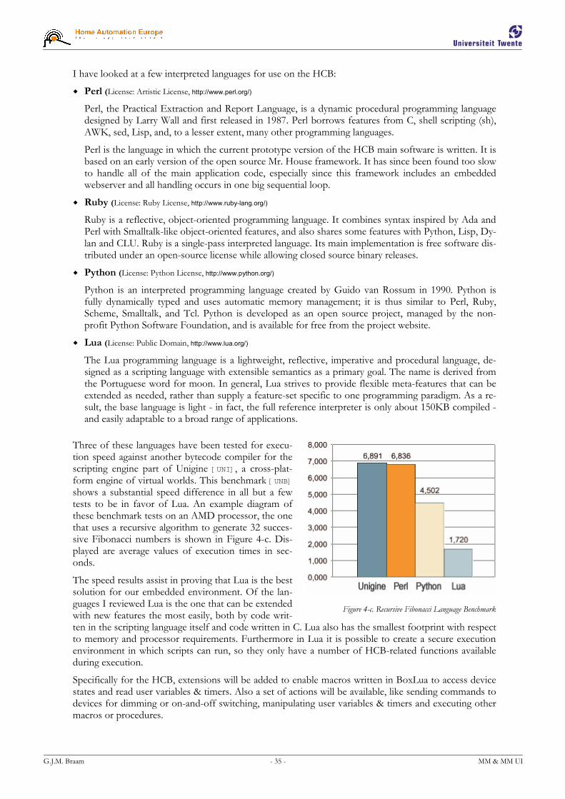
G.J.M. Braam - 35 - MM & MM UI
I have looked at a few interpreted languages for use on the HCB:
� Perl (License: Artistic License, http://www.perl.org/)
Perl, the Practical Extraction and Report Language, is a dynamic procedural programming language designed by Larry Wall and first released in 1987. Perl borrows features from C, shell scripting (sh), AWK, sed, Lisp, and, to a lesser extent, many other programming languages.
Perl is the language in which the current prototype version of the HCB main software is written. It is based on an early version of the open source Mr. House framework. It has since been found too slow to handle all of the main application code, especially since this framework includes an embedded webserver and all handling occurs in one big sequential loop.
� Ruby (License: Ruby License, http://www.ruby-lang.org/)
Ruby is a reflective, object-oriented programming language. It combines syntax inspired by Ada and Perl with Smalltalk-like object-oriented features, and also shares some features with Python, Lisp, Dy-lan and CLU. Ruby is a single-pass interpreted language. Its main implementation is free software dis-tributed under an open-source license while allowing closed source binary releases.
� Python (License: Python License, http://www.python.org/)
Python is an interpreted programming language created by Guido van Rossum in 1990. Python is fully dynamically typed and uses automatic memory management; it is thus similar to Perl, Ruby, Scheme, Smalltalk, and Tcl. Python is developed as an open source project, managed by the non-profit Python Software Foundation, and is available for free from the project website.
� Lua (License: Public Domain, http://www.lua.org/)
The Lua programming language is a lightweight, reflective, imperative and procedural language, de-signed as a scripting language with extensible semantics as a primary goal. The name is derived from the Portuguese word for moon. In general, Lua strives to provide flexible meta-features that can be extended as needed, rather than supply a feature-set specific to one programming paradigm. As a re-sult, the base language is light - in fact, the full reference interpreter is only about 150KB compiled - and easily adaptable to a broad range of applications.
Three of these languages have been tested for execu-tion speed against another bytecode compiler for the scripting engine part of Unigine [UNI], a cross-plat-form engine of virtual worlds. This benchmark [UNB] shows a substantial speed difference in all but a few tests to be in favor of Lua. An example diagram of these benchmark tests on an AMD processor, the one that uses a recursive algorithm to generate 32 succes-sive Fibonacci numbers is shown in Figure 4-c. Dis-played are average values of execution times in sec-onds.
The speed results assist in proving that Lua is the best solution for our embedded environment. Of the lan-guages I reviewed Lua is the one that can be extended with new features the most easily, both by code writ-ten in the scripting language itself and code written in C. Lua also has the smallest footprint with respect to memory and processor requirements. Furthermore in Lua it is possible to create a secure execution environment in which scripts can run, so they only have a number of HCB-related functions available during execution.
Specifically for the HCB, extensions will be added to enable macros written in BoxLua to access device states and read user variables & timers. Also a set of actions will be available, like sending commands to devices for dimming or on-and-off switching, manipulating user variables & timers and executing other macros or procedures.
Figure 4-c. Recursive Fibonacci Language Benchmark

G.J.M. Braam - 36 - MM & MM UI
4.2.4. BoxTalk Support
BoxTalk is the name of the internal application level communication protocol, with which all of the in-ternal and most of the external communication will take place. This protocol will need to support the features and message types mentioned in the requirements.
An extensive look at the BoxTalk Protocol and its inception are given in chapter 5. It describes the weighing factors, the review process, the selection and subsequently the specification of the possible message types.
The BoxTalk library provides functionality to convert BoxTalk messages from their XML string form to a traversable DOM tree in memory, and vice versa. Further a lot of additional functions are provided to perform specific BoxTalk message manipulation like for instance adding another sub-device to a discov-ery message, or generic ones like setting the message’s destination address. Each message type has its own set of auxiliary functions.
4.2.5. Common Driver Functionality
As mentioned before in §4.1.4 ‘Drivers’, there is a library that contains the common functionality that is shared by all the driver processes. This common code actually takes care of the entire main driver execu-tion routine, calling the driver-specific functions to deal with task like hardware initialization, autono-mous actions, handling incoming BoxTalk messages and finally performing de-initialization before a clean driver shutdown.
A complete look at the Driver Model and a clear view of the role that this library plays are given in §4.3.3, which will help explain the existence of this library.
4.2.6. Communication Primitives
The communication that takes place between the Communication Controller and the respective drivers is exactly symmetrical, with the exception that the drivers always are the ones that set up the connection to the Communication Controller. The basic functionality for sending and receiving BoxTalk messages is exactly the same in both directions. Also certain routing primitives are used in the Communication Controller as well as in drivers that need to maintain a dynamic list of connected devices.
This separate library thus encapsulates all the inter-process communication functionality used by all HCBv2 processes. This makes it easy to maintain and allows a possible future switch to other means of communication. The diagram given in §4.3.3 gives a good perspective on where this library fits in the Driver Model.
4.3. Communication
This section describes all the details of the communication between processes within the HCB. A few aspects like BoxTalk, BoxTalk Drivers and the Communication Controller have already been touched on lightly; they will be explained further in the paragraphs to follow. In this section a number of abbre-viations, like for instance hcb_comm for the Communication Controller, will be introduced to avoid men-tioning the full names of the components or libraries again and again. These abbreviations happen to be equal to the actual file names of the binaries on the HCB. An extensive overview of all of the expected shared libraries and program executables can be found in §7.1 ‘Binaries’ of the chapter on Implementa-tion.
4.3.1. Inter-Process Communication
There are a number of different methods with which processes on the same machine can communicate with one another. To select a suitable method for Inter-Process Communication (IPC), the following properties were taken into account: it needs to be able to do two-way communication with arbitrary-length data (generally BoxTalk messages), it must not incur too much overhead and finally it must not be too complex to use.

G.J.M. Braam - 37 - MM & MM UI
I have looked at the following methods with these criteria in mind:
� Signals
Signals only provide a way to communicate with a limited vocabulary: by using integers. Of those, some are reserved and cannot be overridden, like SIGKILL (integer value 9) and SIGSTOP (integer value 19). This means that BoxTalk messages cannot be communicated, so signals are not a viable option.
� Named Pipes
Named Pipes, also named FIFOs, for First In First Out, provide a file buffer for one process to write into, after which another can read from it. Their use comes with the overhead of the file system, be-cause they need to be created in the form of special files in the file system. Besides this overhead this method therefore also leaves a lot of cluttered files that need to be managed.
� Shared Memory
A Shared Memory block is created in kernel memory and is protected by standard UNIX-structured user, group and other file permissions. Shared Memory is very fast, but it still needs some form of data locking, for which semaphores are frequently used, and some form of structure inside the mem-ory block. A shared memory block must be created with a specified size: this imposes limits on the number of messages that could be handled at the same time: it does not scale very well.
� Message Queues
Message Queues can be best described as an encapsulated linked list within the kernel's memory ad-dress space. Messages can be sent to a specific queue and retrieved from the queue in several differ-ent ways. They are also protected by standard UNIX file permissions. Each message queue is uniquely identified by an IPC identifier and protected against concurrent access by multiple processes by its own internal semaphore. A big drawback is however that communication only takes place in one direction, requiring an extra message queue for each connecting process.
� Remote Procedure Calls
A Remote Procedure Call (RPC) server consists of a collection of procedures that a client can call by sending an RPC request to the server along with the procedure parameters. The server will invoke the indicated procedure on behalf of the client, handing back the return value, if there is any. In order to be machine-independent, all data exchanged between client and server is converted to the External Data Representation format (XDR) by the sender, and converted back to the machine-local representa-tion by the receiver. RPC relies on standard UDP and TCP sockets to transport the XDR formatted data to the remote host. This method is rather heavy and relies on a number of system files (/etc/rpc) and other processes (/sbin/portmapper) to function, requiring administrator access to the machine for setting up the specific services. This is not a viable option.
� Sockets
A network socket is a communication end-point unique to a machine communicating on an Internet Protocol-based network, such as the Internet. Sockets are composed of an IP address and a transport protocol port number. Operating systems associate sockets with a running process and a transport protocol like TCP or UDP, with which the process communicates to the remote host. Sockets can also connect on the same machine over the loopback interface. They are simple, flexible, powerful and generate little overhead.
Of the two realistic possibilities that remain, Named Pipes and Sockets, the latter clearly has more ad-vantages over the first. Though we are primarily looking for a means to communicate between processes on the same machine, the added bonus that sockets can transparently be used to connect both locally and remotely make them the method of choice. Especially since this enables simple external connections during debugging and testing.
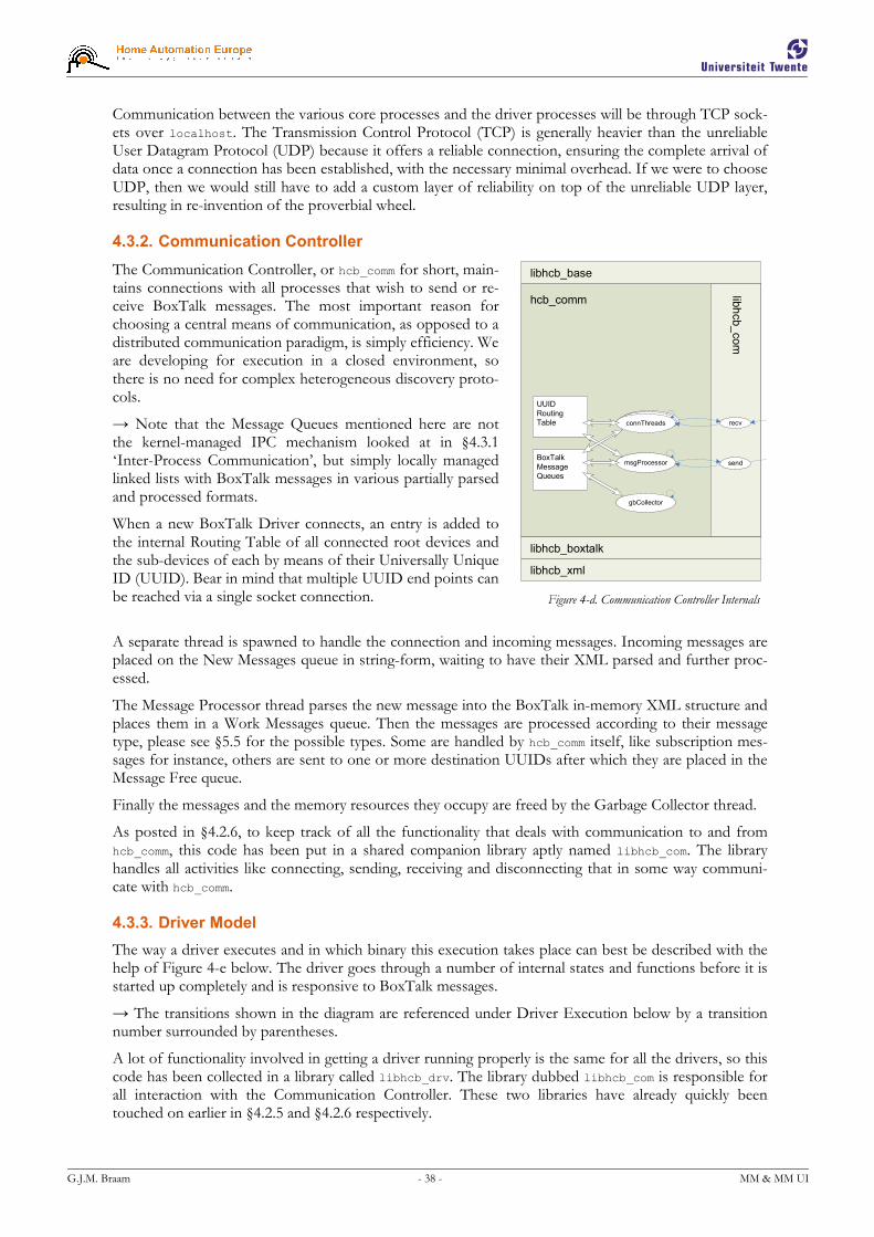
G.J.M. Braam - 38 - MM & MM UI
Communication between the various core processes and the driver processes will be through TCP sock-ets over localhost. The Transmission Control Protocol (TCP) is generally heavier than the unreliable User Datagram Protocol (UDP) because it offers a reliable connection, ensuring the complete arrival of data once a connection has been established, with the necessary minimal overhead. If we were to choose UDP, then we would still have to add a custom layer of reliability on top of the unreliable UDP layer, resulting in re-invention of the proverbial wheel.
4.3.2. Communication Controller
The Communication Controller, or hcb_comm for short, main-tains connections with all processes that wish to send or re-ceive BoxTalk messages. The most important reason for choosing a central means of communication, as opposed to a distributed communication paradigm, is simply efficiency. We are developing for execution in a closed environment, so there is no need for complex heterogeneous discovery proto-cols.
→ Note that the Message Queues mentioned here are not the kernel-managed IPC mechanism looked at in §4.3.1 ‘Inter-Process Communication’, but simply locally managed linked lists with BoxTalk messages in various partially parsed and processed formats.
When a new BoxTalk Driver connects, an entry is added to the internal Routing Table of all connected root devices and the sub-devices of each by means of their Universally Unique ID (UUID). Bear in mind that multiple UUID end points can be reached via a single socket connection.
A separate thread is spawned to handle the connection and incoming messages. Incoming messages are placed on the New Messages queue in string-form, waiting to have their XML parsed and further proc-essed.
The Message Processor thread parses the new message into the BoxTalk in-memory XML structure and places them in a Work Messages queue. Then the messages are processed according to their message type, please see §5.5 for the possible types. Some are handled by hcb_comm itself, like subscription mes-sages for instance, others are sent to one or more destination UUIDs after which they are placed in the Message Free queue.
Finally the messages and the memory resources they occupy are freed by the Garbage Collector thread.
As posted in §4.2.6, to keep track of all the functionality that deals with communication to and from hcb_comm, this code has been put in a shared companion library aptly named libhcb_com. The library handles all activities like connecting, sending, receiving and disconnecting that in some way communi-cate with hcb_comm.
4.3.3. Driver Model
The way a driver executes and in which binary this execution takes place can best be described with the help of Figure 4-e below. The driver goes through a number of internal states and functions before it is started up completely and is responsive to BoxTalk messages.
→ The transitions shown in the diagram are referenced under Driver Execution below by a transition number surrounded by parentheses.
A lot of functionality involved in getting a driver running properly is the same for all the drivers, so this code has been collected in a library called libhcb_drv. The library dubbed libhcb_com is responsible for all interaction with the Communication Controller. These two libraries have already quickly been touched on earlier in §4.2.5 and §4.2.6 respectively.
hcb_comm
libhcb_com
msgProcessor send
recv
UUID
Routing
Table
BoxTalk
Message
Queues
connThreads
gbCollector
libhcb_boxtalk
libhcb_xml
libhcb_base
Figure 4-d. Communication Controller Internals

G.J.M. Braam - 39 - MM & MM UI
libhcb_com
libhcb_drv
libhcb_com
47
10
0
6
Figure 4-e. Driver Process, Libraries, Functions & Communication
Driver Execution
When a driver starts executing the dynamic linker will first load the libraries that are linked to it. Not all libraries that are linked are shown, only the ones that are relevant for the execution and separation of hcb_comm-related functionality. After the libraries have been loaded the process starts (transition 0) in its own main() like a regular C program.
Main right away passes (1) execution on to libhcb_drv, the library that contains all shared code for BoxTalk drivers. At this point the internal state is set to [initializing]. Right away a connection with hcb_comm is set up, as well as some other general initialization like XML configuration file loading and parsing.
Then the driver’s init() function in the driver context is called (2) to allow driver-specific initialization to take place. This and the other functions are called by using function pointers that were initialized in main(). After it is finished execution returns (3) to libhcb_drv.
All initialization is finished and now the run() thread in the driver context is spawned (5). This impor-tant thread is responsible for handling all the continuous and autonomous actions that are needed by the driver to function properly. They usually include timing-specific tasks like interfacing with specific hardware by making use of interrupts or polling mechanisms. This function can also communicate by using the BoxTalk message sending functionality provided by libhcb_com. After the thread is started, the state is set to [up].
Now execution continues (6) to enter into a BoxTalk message receive loop. For the actual communica-tion a receive function in libhcb_com is called (6.1), which blocks until an actual message is sent by hcb_comm. As soon as an actual BoxTalk message has been received and parsed by a function provided by libhcb_boxtalk, execution resumes (6.2) in libhcb_drv. Some generic messages like driver status requests and driver shutdown will be handled here. Messages that are to be handled by the driver are passed on (6.3) to the handler() function, which also implements an important part of the driver-specific behavior. After the message is handled execution continues (6.4) until again it blocks on recep-tion of the next message.

G.J.M. Braam - 40 - MM & MM UI
When the driver receives a BoxTalk message telling it to shut down, execution breaks (7) out of the receive loop and proceeds to shut down the driver in an orderly fashion after changing the internal state to [stopping]. The function deinit() is called (8) to allow the driver to clean up any resources it has allocated during initialization and regular execution. Then (9) after libhcb_com has disconnected itself from hcb_comm and libhcb_drv has cleaned up after itself, the process finally runs out of the main() function with a clean exit (10).
Modularity
The attentive reader might have noticed that the driver binaries themselves actually only provide four functions that determine the entire behavior of the driver. The actual execution order and setup are taken care of by the structure enforced by libhcb_drv. This has been an intentional decision, as this modularity will allow drivers to be easily built as Dynamic Shared Objects in the future, which in turn will enable multiple drivers to actually run inside one driver host process. This structure is analogous to the cvshost.exe services container in Windows XP described in [RUS], resulting in less (relatively heavy) processes with more (relatively lighter) threads.
Resiliency
The Driver Model and the Communication Controller have been set up in such a way that allows the individual drivers and even the hcb_comm process to crash without necessarily affecting the other proc-esses. All processes will be under constant supervision by the omnipotent Watchdog process hcb_watchdog that was introduced in §4.1.7. If a process happens to crash then hcb_watchdog will notice and restart the process in question. It also will periodically check the processes it guards for responsive-ness via a special API. If any process remains unresponsive for a certain period of time, then it assumes it to be hanging and proceeds to try to shut it down with measures successively increasing in force, start-ing with a BoxTalk message and ending with the equivalent of a kill -9 command.
The offending process will then be restarted, during which it will reconnect with hcb_comm and reintro-duce itself. Obviously is also possible for hcb_comm to crash. After it has been restarted all processes will automatically reconnect and proceed to reintroduce themselves.
4.4. Summary
This chapter has given an extensive description of all of the components and libraries that comprise the HCBv2 framework. It has shown the internal dynamics of the components and the ways that the librar-ies and communication tie it all together to support the connected UIs. The chapter demonstrates that the choices for the various open source solutions that will be integrated into HCBv2 are well-informed and made with confidence. The flexibility and the robustness of the driver model have been explained in great detail, because easy and relatively fast driver development is the source of the commercial strength of the HCB.
Until now, I have referred to the communication protocol to be used in the new HCBv2 framework as ‘BoxTalk’. It is now time to talk about it in more detail in the following chapter.

G.J.M. Braam - 41 - MM & MM UI
5. BoxTalk Protocol
In this chapter I will explore the protocol needs for information transport for use with internal and ex-ternal communication in the HCBv2 framework. This protocol has been labeled ‘BoxTalk’ earlier on in this document to be able to reference it without knowing its exact specification at the time. An answer to the research question “What type of protocol or protocols should be used to convey information?” will be provided in the following paragraphs.
First I will revisit the features that are we are looking for in a possible solution and the purposes that it will fulfill in HCBv2. Then the few suitable protocols will be under review that are relevant with respect to our needs, trying to see if there is a match. Next I present the selection with the argumentation support-ing it, followed by a discussion of possible caveats. Finally I present a small specification of the possible mes-sage types, in which all messages will be encapsulated.
5.1. Features
The requirements mentioned in §2.4.1 ‘Data Transfer’ for M4UIs are certainly relevant for the design of the BoxTalk protocol. In a short recap they are: message sending, receiving by server push, reliability, long-term connections, location independence, connection medium independence and authentication & authorization.
Use of the BoxTalk protocol, as derived from the interaction patterns in the HCBv2 definition, will be in the following three communication settings:
� Internally: Driver ↔ Communication Controller
This type of communication takes place within the HCB itself, between two different processes. Key features are message delivery reliability and ease of use. Efficiency with respect to message size be-cause of bandwidth reasons are less important here, and use some form of compression here will only provide extra processing overhead. For now all processes running on the HCB itself are assumed to be safe, so internal authentication is not used.
� Externally: HCB ↔ User Interface Client
Communication with UI clients can take place over multiple types of connection media. The most common of these will be TCP/IP-based, but for instance Bluetooth or Zigbee could also be used to transport BoxTalk messages. Important here are server push, long-term connections and location in-dependence and of course authentication. Also for these connection media the size of the messages does matter, as some of them have bandwidth limitations or there are costs related to the amount of data transferred. Some form of message compression might prove useful.
� Externally: HCB ↔ Service Center
The HAE-operated Service Center will be providing added value services delivered via the HCB Por-tal website. Information will be exchanged with the HCB regularly regarding settings, events and multi-media video streams from cameras. Communication will take place over a secure VPN tunnel, so authentication is not needed.
When looking for a suitable protocol we also need to keep an eye on the types of messages that we will be sending as laid out in §2.5.2 under ‘Message Protocol’. We are therefore looking for a protocol that best fits the needs presented by these features.
Further, HAE has specified that it wants the HCB to eventually be able to act as a compound UPnP device, effectively acting as a representative for all the connected devices that do not have a UPnP inter-face themselves. This does not directly force us to use UPnP as the internal protocol of choice, but keeping it in the back of our heads while reviewing possible protocols is a good idea.

G.J.M. Braam - 42 - MM & MM UI
5.2. Review
A search for protocols that could be good candidates for BoxTalk has yielded the following results. In the boxes to the right an example of what a message using the protocol in question might look like is shown.
� HTTP, HyperText Transfer Protocol
HTTP was initially designed to transfer ASCII text, but has since been extended to also transport binary data. It is more an information transport wrapper than an information format, but the header structure could be coerced to transfer messages without pro-viding actual Content-Length.
� XML, Extensible Markup Language
XML is a free-form markup language without any in-herent semantic structure. It can be used to convey all kinds of information in a way that allows flexible ad-dition of extra information without affecting the ex-isting structure. It is often used as the basis for other, more high-level information carriers, like the way it is being used within SOAP and UPnP. XML has the advantage that it is a generally accepted standard, so parsing and generating libraries are abundantly available for every programming lan-guage.
� SOAP, Simple Object Access Protocol
SOAP is a protocol for exchanging XML-based mes-sages over a computer network, normally using HTTP. It forms the foundation layer of the Web ser-vices stack, providing a basic messaging framework that more abstract layers can build on. Its full imple-mentation sports another bit of overhead on top of the overhead that XML already supplies, so it is not the most efficient with respect to message size.
� UPnP, Universal Plug and Play
UPnP is a set of computer network protocols prom-ulgated by the UPnP Forum. The goals of UPnP are to allow devices to connect seamlessly and to simplify the implementation of networks in any environment. UPnP achieves this by defining and publishing UPnP device control protocols built upon open, Internet-based communication standards.
UPnP actually includes the use of all of the above-mentioned protocols: HTTP, XML and SOAP.
� SNMP, Simple Network Management Protocol
SNMP forms part of the internet protocol suite as de-fined by the Internet Engineering Task Force. The protocol is used by network management systems for monitoring network-attached devices for conditions that warrant administrative attention.
POST /BoxTalk/ HTTP/1.1 Host: hcb.localnet BT-type: notify BT-uuid: lamp-012 BT-serviceid: lamp-012-dim BT-param: dimValue=80
<notify uuid="lamp-012" serviceid= "lamp-012-dim"> <dimValue>80</dimValue> </notify>
<soap:Envelope xmlns:soap="http://schemas.xmlsoap.org/soap/envelope/"> <soap:Body> <notify xmlns= "http://hcb.hae.com/not"> <uuid>lamp-012</uuid> <serviceid>lamp-012-dim</serviceid> <dimValue>80</dimValue> </notify> </soap:Body> </soap:Envelope>
NOTIFY /BoxTalk HTTP/1.1 HOST: hcb.localnet:1900 CONTENT-TYPE: text/xml CONTENT-LENGTH: 149 NT: upnp:event NTS: upnp:propchange SID: uuid: lamp-012 SEQ: 67890436 <e:propertyset xmlns:e="urn:schemas-upnp- org:event-1-0"> <e:lamp-012-dim> <dimValue>80</dimValue> </e:lamp-012-dim> </e:propertyset>
SNMPv2-MIB::host.0 = STRING: hcb.localnet SNMPv2-MIB::eventType.0 = STRING: notify SNMPv2-MIB::UUID.0 = UUID: lamp-012 SNMPv2-MIB::servid.0 = UUID: lamp-012-dim SNMPv2-MIB::key.0 = STRING: dimValue SNMPv2-MIB::value.0 = INTEGER: 80
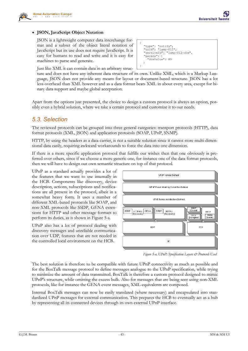
G.J.M. Braam - 43 - MM & MM UI
� JSON, JavaScript Object Notation
JSON is a lightweight computer data interchange for-mat and a subset of the object literal notation of JavaScript but its use does not require JavaScript. It is easy for humans to read and write and it is easy for machines to parse and generate.
Just like XML it can contain data in an arbitrary struc-ture and does not have any inherent data structure of its own. Unlike XML, which is a Markup Lan-guage, JSON does not provide any means for layout or document-based structure. JSON has a lot less overhead than XML however and as a data format beats XML in about every area, except for bi-nary data support and maybe global acceptation.
Apart from the options just presented, the choice to design a custom protocol is always an option, pos-sibly even a hybrid solution, where we take a certain protocol and customize it to our needs.
5.3. Selection
The reviewed protocols can be grouped into three general categories: transport protocols (HTTP), data format protocols (XML, JSON) and application protocols (SOAP, UPnP, SNMP).
HTTP, by using the headers as a data carrier, is not a suitable solution since it cannot store multi-dimen-sional data easily, requiring awkward workarounds to force the data into one dimension.
If there is a more specific application protocol that fulfills our wishes then that one obviously is pre-ferred over others, since if we choose a more generic one, for instance one of the data format protocols, then we will have to design our own semantic structure on top of that protocol.
UPnP as a standard actually provides a lot of the features that we want to use internally in the HCB. Components like discovery, device description, actions, subscriptions and notifica-tions are all present in the protocol, albeit in a somewhat heavy form. It uses a number of different XML-based protocols like SOAP, and non-XML protocols like SSDP, GENA exten-sions for HTTP and other message formats to perform its duties, as is shown in Figure 5-a.
UPnP also has a lot of protocol dealing with discovery messages and unreliable communica-tion over UDP, features that are not needed in the controlled local environment on the HCB.
The best solution is therefore to be compatible with future UPnP connectivity as much as possible and for the BoxTalk message protocol to define messages analogue to the UPnP specification, while trying to minimize the amount of data transmitted. BoxTalk is therefore a custom protocol designed to mimic UPnP’s structure, while omitting the excess bulk. Also for messages that are being sent using non-XML protocols, like for instance the GENA event messages, XML-equivalents are composed.
Internal BoxTalk messages can now be easily translated (where necessary) and encapsulated into stan-dardized UPnP messages for external communication. This prepares the HCB to eventually act as a hub by representing all its connected devices through its own external UPnP interface.
Figure 5-a. UPnP: Specification Layers & Protocols Used
{ "type": "notify", "uuid": "lamp-012", "serviceid": "lamp-012-dim", "params": { "dimValue": 80 } }
G.J.M. Braam - 44 - MM & MM UI
5.4. Discussion
A note regarding the acknowledged inefficiency of XML with regard to message size. In this case the extensibility of XML, the availability of parser libraries including occasional built-in support like with Flash ActionScript and sometimes even 100% compatibility with UPnP messages definitely out-weigh the benefits of using a different, size-efficient data protocol.
If the size of messages will prove to be too large of a delay because of transmission times or if band-width costs for connection media that charge per data unit become too high, it is always possible to ap-ply some form of compression to the XML data stream. Solutions like Binary XML, as for example im-plemented in WBXML [WAP] can be effective in this case.
Also, at this time there are no authentication features yet present in BoxTalk because the communica-tion channels over which BoxTalk will be transmitted are assumed to be safe for now. In a possible fu-ture where 3rd party software developers will be running their own software directly on the HCB plat-form, authentication and especially authorization need to be finalized in the BoxTalk communication framework, so sent messages will be checked to make sure that they correspond to approved identities and have sufficient permissions. Hooks and stubs for this functionality have already been incorporated in the various libraries.
5.5. Message Specification
The BoxTalk messages mimic the UPnP standard as much as possible. For the various non-XML parts like for instance the GENA notify messages, XML equivalents have been designed. Staying close to UPnP will make it possible to let the HCB represent all the connected devices to the outside world as underlying sub-devices, so one HCB could for instance represent 15 lights, 4 curtain controllers, 3 door contacts and 2 motion sensors as sub-devices.
The message types for BoxTalk are specified in Table 6:
Message Description
Discovery Alive This message is sent by a device when it is first brought online. It lists the Services that the message sending Device provides, as well as a list of Sub-devices and their respective Services. In UPnP this message is sent using SSDP, a broadcast protocol standard, for the HCB there already is a permanent message infrastructure present, so a true IP broadcast is not needed.
Discovery ByeBye The ByeBye message lets other systems know that certain Devices and therefore their Services are no longer available. This message is also not sent using SSDP, like the Alive message.
Device Description Request
The request message is fairly simple, only requesting an extensive Device Description for a certain device.
Device Description Response
A message listing a detailed device description including a list of supported Services and a list of Sub-devices for which the details can be retrieved by sending it a separate Device Description request.
Service Description Request
Again a simple request for an extensive description of the Services that a Device provides.
Service Description Response
Gives a detailed description of the Services that a Device can provide. This includes a list of Actions with their allowed arguments & their formats and State Variables that can be Queried and Subscribed to.
Action Invoke An Action Invoke message is essentially an XML form of a remote procedure call with optional parameters, which in UPnP is sent according to the SOAP protocol. The Ac-tions that can be invoked and their respective arguments are listed in a Service Description Response message.

G.J.M. Braam - 45 - MM & MM UI
Action Response This is an asynchronous response to a previously sent Action Invoke message. It can con-tain zero or more arguments that are returned from the Action.
Query Request The actual value of a State Variable can be requested by sending this message to a Device. A list of the available State Variables provided by a device are listed in a Service Description Response message.
Query Response A Query Response contains the answer to a Query Request message, simply returning the actual value of the requested State Variable at this time.
Subscribe When you want to receive a Notify message when the value of a State Variable changes, you can Subscribe to it. The caller will receive Notify messages from then on about state changes.
Unsubscribe As soon as an entity is no longer interested in receiving Notify messages for State Vari-able changes, an Unsubscribe message will cancel the subscription.
Notify This is the message that will inform an interested entity that a State Variable has changed state after it has Subscribed to it.
Table 6. BoxTalk Message Types
→ This quick description of the possible message types is given here because there are a lot of refer-ences to these messages in this document.
Please see Appendix I ‘BoxTalk Message XML Templates’ for a full list of templates for the various BoxTalk messages.
5.6. Summary
In this chapter I have shown that the internal message protocol needs for HCBv2 are best fulfilled with a custom protocol that mimics the structure of the UPnP standard. Also in anticipation of future exter-nal UPnP support, messages will follow UPnP as much as possible, after however removing some of the message overhead and defining XML-equivalents for non-XML UPnP parts. Options for possibly using Binary XML for compression purposes and integrated authentication are kept open for the moment.
Now that an extensive definition of the HCBv2 framework and the internal BoxTalk protocol have been given, we can proceed with the preparations that were needed before I could proceed with the imple-mentation phase of the software for the HCB.

G.J.M. Braam - 46 - MM & MM UI
6. Preparation
This chapter explains the steps that I took before starting on the actual implementation of HCBv2. It describes the build environment that I created and the techniques I used to achieve a maximum in de-velopment comfort for myself and other software developers working with the framework.
First described are the preparations that I made to familiarize myself with Producing Binaries for the em-bedded platform we will be developing for and getting to know and setting up the low-level building tools. Next is a description of the more high-level Development Software & Tools that I introduced. The use of these tools has severely improved the logistic side of the development process.
6.1. Producing Binaries
Before software can be created to run on the HCB a couple of low-level details needed investigating, understanding and getting used to. They are mostly the preparation of tools and eventually a feature-rich development script that will be used by myself and other driver developers.
6.1.1. ARM Platform
To create binaries that can execute on the ARM platform a cross-compiler toolchain was needed. In the beginning we were using the toolchain that was supplied by Chess, the hardware and core O.S. supplier. This toolchain seemed to produce unreliable binaries that would crash at seemingly random points with a SIGILL signal, an illegal instruction. After some investigating it turned out that this toolchain created binaries with embedded Hardware Floating Point instructions, a feature which the embedded ARM processor on the HCB does not have. Apparently some network utilities like ping, created earlier with the same toolchain, only use integer math and ran without problems.
As a part of trying to find out what happened I made my own ARM cross-compiler toolchain. This is not a task for the faint of heart, for you need to build binutils, gcc, and glibc for your platform. I used an excellent piece of software called crosstool to help generate it. It produces the arm-linux-* executa-bles needed to make binary objects that can execute on the ARM platform. Creating this toolchain my-self has given me a lot of insight into the creation of executables for the linux platform and the separate sets of dependencies that exist to both create and run them. (Link: http://www.crosstool.org/)
6.1.2. Kernel Features
The in-memory database system FastDB, chosen to provide the internal repository, requires the Sys-temV-style [SYS] Shared Memory and Semaphore APIs, functionality that was not present in the stan-dard kernel that runs on the HCB provided by Chess. By request, a special supplemental IPKG feed that acts as an update to the regular feed provides a new kernel and the accompanying loadable kernel mod-ules that were compiled with the System V IPC features enabled. These features will be enabled by de-fault in the next official software release by Chess.
6.1.3. Build Process
For the software components to be developed for the HCB a set of general build configuration files was set up that make use of the GNU utilities autoconf, configure and make. This combination of tools makes it significantly easier to do compilation and cross-compilation from the same source tree.
The configuration files are used sequentially as follows: autoconf generates a configure script from the input file configure.in. Then configure can be run with some parameters specifying things like installa-tion paths which in turn will generate a Makefile from the Makefile.in input file. The build system is now configured to build both ARM and i686 binaries. A regular make command will now produce the ARM binaries, while a make NATIVE=1 will create binaries that can run directly on the development machine, significantly speeding up the development process. Both builds have their own intermediate build files so incremental building is still possible, also resulting in an overall development speed increase. (Links: http://www.gnu.org/software/autoconf/, http://www.gnu.org/software/make/)

G.J.M. Braam - 47 - MM & MM UI
6.1.4. Package Distribution
The software distribution system IPKG is used by Chess for all its embedded linux solutions. IPKG, the Itsy Package Management System, is a light-weight derivative of Debian’s DPKG system, created spe-cifically for embedded platforms. Sources are available in the form of data feeds that can be distributed via a regular web server. Packages all have a version associated with them and can have dependencies on other packages. Packages are created from a base directory and contain a simple ASCII control file that specifies properties like the name, version, dependencies and a small description. The basic packages for the linux operating system and commonly present applications, provided by the hardware supplier Chess, are also distributed in the form of a feed.
To facilitate development I set up a separate feed on a development machine that is configured so new packages can be uploaded to it automatically and new package index files are also automatically gener-ated. Freshly created packages can therefore easily be deployed to one or more HCBs for testing. Ana-logue to Debian’s apt-get, IPKG uses ipkg update to get new package lists, ipkg install fictional-pkg to download and install a fictional package and ipkg upgrade to upgrade all installed packages to their latest versions.
(Link: http://handhelds.org/moin/moin.cgi/Ipkg)
6.1.5. Automating the Process
The hcb-configure script is a general build tool I made shown in Figure 6-a that first pre-pares some files and then consecutively runs configure, make, make install, make ipkg and make ipkg-install, resulting in the new pack-age to be available for test-deployment on one or more HCBs immediately.
hcb-configure creates the base directory and the control file to build a package. It automa-tically inserts a previously configured main-tainer name and the latest version string, which is partly based on the project’s subversion revi-sion number. It also adds two new targets ipkg and ipkg-install to the existing Makefile in the project directory.
Next it runs configure to prepare for cross-compilation using the arm-linux-* toolchain executables and specifies the installation path via the --prefix parameter. Now a regular make clean all install sequence is run to build the software, followed by the special make ipkg ipkg-install targets to handle the actual package creation, the uploading of it to the test feed and the regeneration of the package list.
hcb-configure was created with some useful optional parameters allowing the entire process to be run without user interaction from inside an Integrated Development Environment like for instance Eclipse. Also note that after the script has been run once, it is possible to manually run all make targets.
Figure 6-a. Processes Automated by hcb-configure

G.J.M. Braam - 48 - MM & MM UI
6.2. Development Software & Tools
To help the actual software creation process a number of higher-level tools are used. The tools de-scribed in the next few paragraphs are the ones that are used the most extensively by developers during the software creation process.
6.2.1. MediaWiki
During the development a lot of information is constantly being generated, used and re-used to docu-ment the design choices, available libraries, API functions and implementation choices. MediaWiki is used to structure and organize this data and at the same time make it easy to change and re-structure this information. MediaWiki is the wiki system that is used on Wikipedia.org, the online community encyclo-pedia. It is based on the idea that everybody in a community can add to or change existing pages in a collection. The HCB Wiki collection currently consists of about 45 articles of lengths varying from 5 to 500 lines, most of which were written by me.
(Link: http://www.mediawiki.org/)
6.2.2. Subversion
To facilitate software development with multiple developers and to have a central place where all the code is stored a Version Control System is used. Subversion, or SVN for short, is the successor of the Concurrent Versions System [CVS] and a powerful tool that accomplishes this task.
I have configured the subversion repositories to be accessible from the network by using the mod_svn module running under an Apache web server. Subversion clients can exchange data with the develop-ment web server by using SVN over the Web-based Distributed Authoring and Versioning (WebDAV) protocol [DAV].
Subversion also provides powerful means to allow multiple developers to work on different branches of the same project, while still enabling them to take advantage of each other’s improvements. The revi-sions are based on the changes made to individual lines, so multiple developers can even work on the same files, provided that they do not modify the same lines. Even then those edit conflicts are often eas-ily resolved.
(Link: http://subversion.tigris.org/)
6.2.3. Eclipse
Eclipse is a cross-platform Integrated Development Environment (IDE) written entirely in Java. Al-though primarily written to develop Java software, an extensive C/C++ Development Toolkit (CDT) is available. Among other things it provides support for C/C++ syntax checking and highlighting, code completion and support for managed & unmanaged make builds.
I have facilitated remote building on the development server by using the console version of PuTTY’s SSH client plink.exe and Public Key Cryptography [PKC] to avoid having to type a login password for each build. It is now possible to perform the entire build command make clean all install ipkg ipkg-install directly from inside Eclipse. Any warnings and/or errors are automatically shown in the integrated file editor at their respective line numbers. Complete integration of all CVS and SVN func-tionality into Eclipse also contribute to this very useful and efficient development environment.
(Links: http://www.eclipse.org/, http://www.chiark.greenend.org.uk/~sgtatham/putty/)
G.J.M. Braam - 49 - MM & MM UI
6.2.4. Doxygen
Documentation for the applications and libraries is automatically generated using Doxygen. This docu-mentation is placed on the development web server and used as a reference by driver developers for the different library APIs. The code is generated from comments placed in the code according to various formats. Supported are various variants of JavaDoc, Qt-style documentation and C-style // comments. The doxygen documentation generation process is integrated into the SVN versioning system. Directly after a commit to a subversion repository, the doxygen process is executed to generate documentation for the new code, which in turn is directly accessible via the intranet. The Doxygen pages are often linked to for reference from the HCB Wiki articles.
(Link: http://www.doxygen.org/)
6.2.5. Valgrind
Valgrind, pronounced val-grinned, is a test tool suite for ELF binaries. It can run the binaries on a software i686 CPU emulator and can perform tests like trace memory leaks, track cache usage and most impor-tantly reads/writes at invalid memory addresses that usually result in a SIGSEGV, a segmentation fault. It also keeps track of all malloc and free calls making it possible to track down hard-to-pinpoint memory leaks. If the binaries are compiled with debug information (gcc –g), it can also tell you exactly on which line of your source code the error occurs, including a stack trace right up to the instruction in question. This is also one of the reasons that all code developed for the HCB should also be able to run on an i686 machine.
(Link: http://www.valgrind.org/)
6.3. Summary
The scripts, techniques, software and tools described in this chapter have contributed significantly to the logistic part of the development process for the software developers that work on HCBv2 or on related Drivers at HAE. As a whole I feel it has resulted in a higher level of quality of the software produced and has helped to guide myself and other developers alike into better software creation practices.
Now that the preparations are completed, we can take a look at what the implementation of the HCBv2 framework entailed, up to the point where it can actually support user interfaces.

G.J.M. Braam - 50 - MM & MM UI
7. Implementation
Described here are the last steps taken towards the completion of the HCBv2 framework inside the scope of my graduation project. As expected, the size of the framework prevents it from being com-pleted entirely before my graduation, although it can support a few prototype UI clients at the time of writing.
First I will show that the design process has culminated in the creation of the core, library and driver binaries, that together compose the framework. Then I will highlight a couple of interesting aspects of the implementation like the development of some of the hardware drivers and the creation of the web server, which was simultaneously developed with the first user interfaces.
For a complete list of software versions that I have built for investigation, development, testing or de-bugging purposes during the course of this project please see Appendix II ‘List of Built Software’.
7.1. Binaries
Most of the components described in §4.1 ‘Components’ will be executable processes. Figure 7-a shows the processes that could be running on an HCB at a given time, shown as rounded rectangles:
Figure 7-a. Possible active processes and drivers running on the HCB
A short description of each of the binaries that I designed and created for the HCB are given in the next three paragraphs. Their multitude and diversity give an indication of the complexity of the entire project.
A short note for libhcb_data: whether or not it needs a separate process to manage the repository is not evident yet. This will become clear when the repository usage patterns by the various hardware drivers can be observed.

G.J.M. Braam - 51 - MM & MM UI
7.1.1. Core Processes
The core processes (hcb_*) are processes that always run on the HCB. The watchdog process makes sure that all these processes are running and are responsive to BoxTalk messages, possibly recycling and restarting processes where needed.
� hcb_watchdog makes sure all processes are up & responsive
� hcb_comm acts as central communication hub for all BoxTalk messages
� hcb_core manages all application logic & configurations
� hcb_log provides logging services transparently via API & BoxTalk messages
� hcb_netconnect supervises net connectivity and VPN tunnel to Service Center
� hcb_web delivers Perl/static web content & BoxTalk-over-HTTP
� hcb_upnp represents us as a compound device with all sub-devices via UPnP
� hcb_voip relaying of Voice over IP [VOI] connections using [SIP] & [RTP]
7.1.2. Driver Processes
The driver processes (hdrv_*) are processes that not necessarily always run on the HCB. Whether they run or not depends on the devices that are attached to an HCB at a specific time. Their execution status is also supervised by the hcb_watchdog process.
� hdrv_hcbhw interfaces with the on-board 8 digital IN/OUT ports & LEDS
� hdrv_a10x10 controls the on-board A10/X10 Xanura interface component
� hdrv_konnex handles communication with a KonneX/EIB bus coupler
� hdrv_zigbee enables access to the next-gen wireless protocol Zigbee
� hdrv_rfxcom supports RF systems like Visonic, KlikAan-KlikUit, X10-RF, Koppla
� hdrv_honey interacts with the Honeywell networked appliance protocol
� hdrv_phone controls on-board modem, detects DTMF codes, plays voice samples
� hdrv_* …any other drivers that may be developed in the future…
7.1.3. Dynamic Shared Objects
These modules will be implemented as Dynamic Shared Objects so the contained functionality can eas-ily be accessed from different executables and by different developers. The APIs are documented exten-sively to allow for easy use and expansion by internal or 3rd party developers.
� libhcb_base basic functionality like config, translation, lists, logging
� libhcb_boxlua embedded Lua interpreter, extended with device accessing & actions
� libhcb_boxtalk creation/parsing/manipulation of BoxTalk messages
� libhcb_com local socket connections with hcb_comm, routing management
� libhcb_data in-memory repository, wrappers for internal data structures
� libhcb_drv generic control of BoxTalk drivers, generic driver functionality
� libhcb_xml contains and exposes ezXML library

G.J.M. Braam - 52 - MM & MM UI
7.2. Hardware Drivers
Described here are the first of the drivers that have been developed by me, or by other developers at HAE with my guidance. Their development has been in the order given.
NULL Driver
After the initial driver design was completed, implementation of libhcb_drv and libhcb_com followed for communication with hcb_comm using hdrv_null as a test driver. The attentive reader might have no-ticed it being mentioned on the right side of Figure 4-e ‘Driver Process, Libraries, Functions & Com-munication’ in §4.3.3 ‘Driver Model’. The null driver was developed as some sort of a Driver Develop-ment Kit for HCBv2. It only controls the four built-in LEDs on the external HCB housing and is used as an ‘empty driver’ project for developers that are new to HCBv2. As an example, it demonstrates all the functionality and just about all of the framework API functions that are available to driver develop-ers. I also use it myself as a skeleton for new drivers.
Zigbee Driver
When the null driver was sufficiently stabilized I started work with a colleague doing his internship at HAE to convert his prototype Zigbee driver into hdrv_zigbee, the first actual hardware driver that used the new framework. Conversion of his driver to the new framework turned out to be quite forward, af-ter applying our common coding standards and some general code optimization. The code fit nicely in the init, run, handler and deinit functional containers enforced by the driver structure. The driver provides access to the light, temperature and humidity sensors on the experimental Zigbee development boards. It is also possible to receive events from the buttons and to turn the LEDs on the boards on and off. Zigbee is still a very young standard, so there are no commercial products yet available on the market at the time of writing. The Zigbee standard mainly describes a general networking layer, over which arbitrary data can be sent. Zigbee needs to specify general message communication standards, so similar competing products can work together in the same network, somewhat like the UPnP Forum is doing now with device profiles.
A10/X10 Driver
Converting the A10/X10 driver prototype into hdrv_a10x10 together with another HAE co-worker also did not present any serious problems. A10 is an extension to the common X10 protocol sold under the Xanura product line by Eaton-Holec. The CTX interface built into the HCB receives all A10 and X10 commands sent over the power line. Some mutual exclusion locking had to be applied to the data struc-tures that keep track of the device states, because the two threads run and handler try to access the data simultaneously. The A10/X10 driver is being used as a test driver to develop the initial internal structure of the data repository. Another reason for choosing hdrv_a10x10 is the plan to remove A10/X10 han-dling from the legacy Perl application and start using the new framework for this functionality. This will create an old-new system hybrid and at the same time relieve some digital pressure from the already overly strained Perl process.
HCBhw Driver
The HCB Hardware driver provides support for the 8 digital input and 8 digital output ports that are integrated on the HCB PCB. Also the status of the switch on top, currently used to disable external internet access to the HCB, is managed by this driver. The in- and output ports are used to connect cus-tom electric components to the HCB. This relatively simple driver was made by yet another HAE col-league in under a day.
Development has just started on two other new ones, the Phone and RFxcom drivers.

G.J.M. Braam - 53 - MM & MM UI
7.3. Web Server
The web server component hcb_web is based on SWILL, the Simple Web Interface Link Library [SWI], released under the Lesser GNU Public License. This library provides functionality to easily add serving of web content to any C-based application. It is originally a single-threaded API which I extended heav-ily in order to support the suspended connections to each of the external clients while at the same time still serving regular browser requests.
Currently three types of requests on port 80, the usual one for HTTP traffic, are handled differently by the web server:
� BoxTalk messages POSTed to the /boxtalk/ location are relayed to hcb_comm. Any messages that need to be routed to a connected client are sent over the server-side suspended connections that were still waiting for a response. This connection is then closed, after which the client will immediately make a new connection, probably without actually having something to say: the point is to have a connection ready for the server to reply to. If the client wants to send a message it will close the exist-ing connection and set up a new one with the message as part of the POST request data.
� Perl files (*.pl) are handled by performing a special internal proxy request. The handling routine connects to the legacy Perl application running locally on port 79, does the request and sends back the response it receives to the client. A connected external client does not know or care that this hap-pened internally.
� Other requests are for static files that are served from the /HCBv2/www directory on the flash disk. Currently there is no CGI or other server-side scripting language planned for web interaction: all dy-namic content will be provided and generated by client-side JavaScript using AJAX-like techniques [AJA] with BoxTalk.
This internal redirection ensures that forwarding all user-related traffic to an HCB is possible because it takes place over a single port. These requests can even be encapsulated by a web proxy or other web forwarding services because all requests and responses are strictly HTTP, ensuring maximum connec-tivity even from browser environments restricted by severe firewall limitations.
The setup with three-way functionality multiplexing on port 80 also allows for a gradual transition to the new system with some parts still being handled by the legacy Perl application. Over time more functio-nality will be moved over to the new framework, relieving work from the significantly slower Perl appli-cation and ultimately making it obsolete.
The web server has been developed simultaneously with the user interfaces in next paragraphs.
7.4. User Interfaces
The clients listed here are announced to hcb_comm using a BoxTalk Discovery message as soon as they connect. The web server hcb_web acts as a BoxTalk message conduit to hcb_comm. These are the clients currently in development or planned to be developed in the near future:
7.4.1. Flash Application
The Flash Application is the UI client that is the most feature rich at the time of writing. A working prototype of this application, a con-tinuation of an earlier demonstration interface, is available and runs as a standalone executable on the PocketPC platform and as a Shockwave Flash object in a web browser. Using WiFi or GPRS/UMTS it obtains and displays the rooms in the house with in each the configured devices. These rooms can be navigated, on which the UI dynamically generates new controls for the devices in a room.
Figure 7-b. HCB Lite Control - Connect
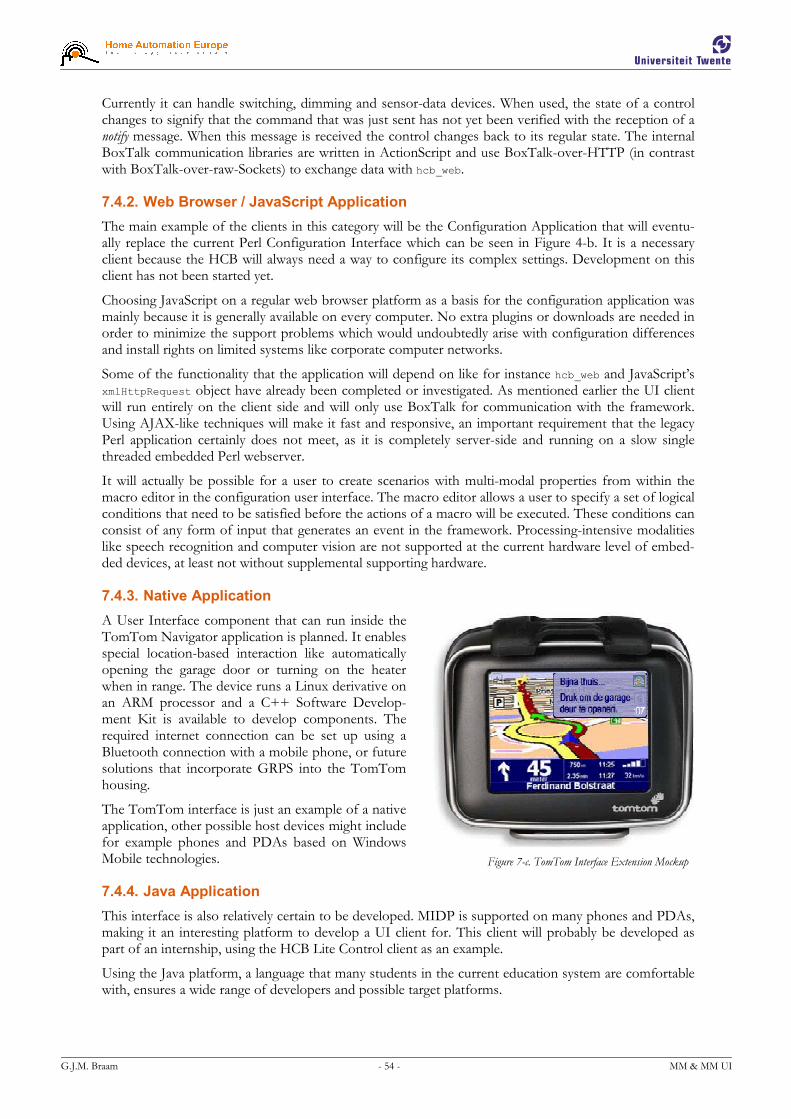
G.J.M. Braam - 54 - MM & MM UI
Figure 7-c. TomTom Interface Extension Mockup
Currently it can handle switching, dimming and sensor-data devices. When used, the state of a control changes to signify that the command that was just sent has not yet been verified with the reception of a notify message. When this message is received the control changes back to its regular state. The internal BoxTalk communication libraries are written in ActionScript and use BoxTalk-over-HTTP (in contrast with BoxTalk-over-raw-Sockets) to exchange data with hcb_web.
7.4.2. Web Browser / JavaScript Application
The main example of the clients in this category will be the Configuration Application that will eventu-ally replace the current Perl Configuration Interface which can be seen in Figure 4-b. It is a necessary client because the HCB will always need a way to configure its complex settings. Development on this client has not been started yet.
Choosing JavaScript on a regular web browser platform as a basis for the configuration application was mainly because it is generally available on every computer. No extra plugins or downloads are needed in order to minimize the support problems which would undoubtedly arise with configuration differences and install rights on limited systems like corporate computer networks.
Some of the functionality that the application will depend on like for instance hcb_web and JavaScript’s xmlHttpRequest object have already been completed or investigated. As mentioned earlier the UI client will run entirely on the client side and will only use BoxTalk for communication with the framework. Using AJAX-like techniques will make it fast and responsive, an important requirement that the legacy Perl application certainly does not meet, as it is completely server-side and running on a slow single threaded embedded Perl webserver.
It will actually be possible for a user to create scenarios with multi-modal properties from within the macro editor in the configuration user interface. The macro editor allows a user to specify a set of logical conditions that need to be satisfied before the actions of a macro will be executed. These conditions can consist of any form of input that generates an event in the framework. Processing-intensive modalities like speech recognition and computer vision are not supported at the current hardware level of embed-ded devices, at least not without supplemental supporting hardware.
7.4.3. Native Application
A User Interface component that can run inside the TomTom Navigator application is planned. It enables special location-based interaction like automatically opening the garage door or turning on the heater when in range. The device runs a Linux derivative on an ARM processor and a C++ Software Develop-ment Kit is available to develop components. The required internet connection can be set up using a Bluetooth connection with a mobile phone, or future solutions that incorporate GRPS into the TomTom housing.
The TomTom interface is just an example of a native application, other possible host devices might include for example phones and PDAs based on Windows Mobile technologies.
7.4.4. Java Application
This interface is also relatively certain to be developed. MIDP is supported on many phones and PDAs, making it an interesting platform to develop a UI client for. This client will probably be developed as part of an internship, using the HCB Lite Control client as an example.
Using the Java platform, a language that many students in the current education system are comfortable with, ensures a wide range of developers and possible target platforms.
G.J.M. Braam - 55 - MM & MM UI
7.5. Summary
Before work can start with UIs we need a framework that has all the necessary components to support these UIs. So essentially my priorities have been focused on first implementing the basic communication and message handling capabilities of the framework. At this point work could start on the UI clients with their side of the message protocol and communication logic. With the communication channel fi-nally reaching this far, it was time for the graphical implementation and the details of the UI look & feel.
With this framework the driver developers are handed the tools to enable them to keep focused on the hardware that they are writing support software for: they need to have minimal knowledge of the frame-work to do their jobs. Their main task is to translate incoming BoxTalk messages to hardware com-mands and vice versa, taking into account the inevitable minor incompatibilities that exist between the two domains. Extra logic code has to be added to overcome these minor incompatibilities.
UI developers have the simplest of the development tasks with respect to code complexity: they only have to support generalized BoxTalk messages and can work on the UIs in the language and environ-ment that they are comfortable with. They do not have to deal with specific low-level details of certain devices.
End users that will be operating the UIs can expect clients that are both responsive and display coherent states across different simultaneously operated devices. Especially responses to using the client for the PocketPC have been very positive, and resulted in some extra feature requests, of which some – like support for sensor data – have already been implemented.
The framework has proven to be a solid and stable base for connecting devices and UI clients, as has been noted by internal developers and test-users of different versions of the prototype system.
This chapter concludes the description of the work that I have done at Home Automation Europe, next up are the conclusions that can be drawn as a result of the work, directed towards answering the secon-dary research questions composed at the beginning of this document.

G.J.M. Braam - 56 - MM & MM UI
8. Conclusions
In this chapter I will formulate an answer to the main research question by first answering the secondary research questions in the paragraphs to follow. The original main research question is:
How should a flexible architecture that provides support for multi-modal and multi-medial user interface clients,
while running in a severely resource-limited embedded environment be developed?
The secondary questions will be answered in the paragraphs that will elaborate on results regarding the BoxTalk Protocol, the Home Control Box v2 Framework, Driver Development and Support of M4UIs. I will finish this chapter with a General Conclusion of my work.
8.1. BoxTalk Protocol
“What type of protocol or protocols should be used to convey information?”
It has been shown that a custom protocol is the best solution for BoxTalk, the internal message proto-col used with the new HCB framework. Homing in on future HCB support for Universal Plug and Play, it mimics UPnP as much as possible, but replaces the non-XML parts of the UPnP protocol-set with XML counterparts. XML has been selected as the main data carrier for the protocol, valuing reasons of general flexibility, familiarity and support over message size efficiency. Possible future constraints of transfer costs over narrowband connections can be remedied by adding support for one of the varia-tions of Binary XML for compression.
BoxTalk suits the data needs of M4UIs very nicely. It can transfer commands, events, element status updates and in the future even multi-media components for use of the client UIs. It is therefore power-ful enough to handle all current and most future message needs.
8.2. HCBv2 Framework
The HCBv2 framework is still under development, with myself as lead developer. Approximately 70% of the core framework is completed at this time, not counting the progress on drivers and on user inter-faces. At the time of writing the framework can support UI clients that connect via TCP/IP to the web server, as well as control devices that are connected by means of A10/X10 or Zigbee hardware.
“Who will be the users of the system, and what will they expect from it?”
The developing users, for both Drivers and UIs, can focus on their core competences. The only things they need to familiarize themselves with are communication by means of the internal BoxTalk protocol and some minor API functions. BoxTalk provides an abstraction level between Drivers & the frame-work on one side and UIs & the framework on the other side.
The configuration and operation users can expect to be using fast and feature-rich UIs, supported by server-push communication and BoxTalk. Uniform methods are available for them to control and check the status of a wide variety of connected devices via a consistent look & feel. An operation UI is dem-onstrated with the HCB Lite Control application I developed for the PocketPC.
“How to set up a solid base framework to support the functionalities that the UIs will be needing?”
The framework has proven to be a solid and stable base for connecting devices and UI clients, as has been noted by internal developers and test-users of the prototype system. UI logic can send commands to rooms and devices it finds in the Home Layout Message, which will automatically be routed to the responsible driver by the framework. The UI logic has access to the extra information also provided by the Home Layout Message, so it can maximize the user experience of the person that operates the UI. Internal supportive components like logging, persistent data storage, internationalization and the com-munication subsystem provide a strong foundation for the UIs to run on.
Also, the fact that messages originating from the framework are received by clients instantaneously greatly improves the action response times as part of the user experience.

G.J.M. Braam - 57 - MM & MM UI
8.3. Driver Development
“How to incorporate maximum flexibility to support current and future technologies?”
The whole framework is based on code written in ANSI C, without using any HCB-specific hardware features, so it can also run on other linux-based platforms. In the future it will be possible to easily up-grade to a different embedded platform. Also, the modular design for the drivers will make the addition of support for selective current and future communication technologies relatively easy. Recent driver development for the framework has proven it both flexible and easy to extend. Adding support for the three drivers that are fully functional at the time of writing, A10/X10, Zigbee and HCBhw, has been straightforward and refreshing, as stated by their developers. This way the problems and complexity as-sociated with a certain technology are nicely encapsulated within its own driver module.
8.4. Support of M4UIs
“What demands does this system have with respect to data communication to and from the UIs?”
The server-push feature of the main UI connection provider, an extended web server, provides instan-taneous message transfer to connected clients, greatly improving the action response times as part of the general user experience. Even from PocketPC clients which connection route takes messages over WiFi, the Service Center, the SSH tunnel to an HCB, and finally to the embedded web server, generally have total round trip times of less than ½ a second, which is well within the stipulated two second limit.
Message delivery is made reliable both in the framework as well as to and from connected UI clients. Delivery is ensured by using techniques like message acknowledgements and sequence numbers. Loca-tion independence is achieved by mainly making use of connection media that itself are not bound to a specific location. If location-specific connection media are used to save on costs for example, then the possibility exists to switch to non-local equivalents when the first is not available anymore.
8.5. General Conclusion
Developing for an embedded platform like the HCB offers quite a few challenges on top of those that development for more regular platforms provide. You have to be aware of and take into account the differences concerning constraints regarding cross-compilation, target system resources, development and above all those for execution & debugging.
In its current state the framework offers a solid base to build on in terms of driver stability, message delivery and distributed user interface element state consistency. The BoxTalk protocol is flexible and ready for current and future communication needs, also with respect to future transport of multi-media UI elements.
Multiple UI instances have been tested simultaneously from different platforms. Especially the Pock-etPC interface has proven to be a good example of the dynamic capabilities of the framework. Response times for round-trip messages are below half a second and thus well within the usable limit specified in the requirements.
Sequential multi-modality is supported, and it will actually be possible for a user to create scenarios with multi-modal properties with the macro editor in the configuration user interface. Processing-intensive modalities like speech recognition and computer vision are not supported at the current hardware level of embedded devices.
G.J.M. Braam - 58 - MM & MM UI
9. Epilogue
9.1. Discussion
Before the work on user interfaces or message communication could start, a large amount of basic sys-tems needed to be working first. The supportive libraries and executables like the Communication Con-troller are required for message creation, sending and parsing. The web server component is necessary to keep track of and relay messages to user interface clients connected via TCP/IP. These dependencies resulted in the need to implement a large part of the framework before work could start on the human interaction part.
We Want More!
An interesting phenomenon I noticed was that users, when playing around with a prototype, were de-manding more and more functionality. When the framework was in a shape where small demonstrations could be given, and users could mess around with a prototype there were numerous requests for new features like “can it also display values for sensors?” These experiences were also observed by Gordon and Bieman in [GOR].
Communication Controller Queues
As a part of the Communication Controller internals, the current implementation works with incoming messages in terms of an entire queue. Incoming messages arrive in a New Queue where they wait un-processed until the Work Queue is free for access. Messages in the Work Queue are parsed, processed and rerouted to one or more possible recipients, staying there until the Free Queue is actually empty. The Free Queue holds messages that are processed and await garbage collection. This means that all messages in a queue need to be processed before the entire queue can be ‘migrated’ to the next. This could theoretically turn out to be inefficient during high load, which has however not yet been seen dur-ing testing. This structure was necessary because at first it was unclear if the XML parser, still undecided at that time, was fully thread safe, so there was a need to handle all XML parsing sequentially in one thread. Now that we know that the XML parser is thread safe, there is a lot of room for improvement.
Other Platforms
The new HCBv2 Framework is written to for the Linux operating system in straight ANSI C code and does not make use of specific HCB hardware features, so it is possible to port the framework to other similar platforms without any problems.
At the time of writing talks are in progress regarding a certain set-top box to possibly use the HCBv2 framework as their internal software basis. They have aspirations towards home automation and can make good use of the features that the new framework provides.
Cascade Edits
Because many of the libraries in this framework are highly interdependent, it turned out to be impossible to complete large parts of a single library consecutively. New functionality in one library would need unfinished features in another, sometimes requiring modifications in up to five libraries simultaneously. It is often hard to avoid these cascade edits, since first versions of a specification made for even a single library are seldom complete or error-free. These situations will happen more often in the early stages of framework development, since then all libraries are still in a pre-mature state.
Using Map UIs
Future versions of UI clients that have enough screen real estate might be using small location maps of the home to specify the devices that can be controlled, instead of navigating through lists of rooms with lists of devices. Accompanying future versions of the configuration interface would allow you to ‘draw’ a map of your rooms and then pin devices to specific locations on them. This would provide an even more intuitive UI to the end users.

G.J.M. Braam - 59 - MM & MM UI
9.2. Related Work
There is not a lot of work focusing on facilitating the practical integration of home automation compo-nents by creating an intelligent and flexible solution. The HCB could however prove to be a very useful component in a number of existing projects.
Maior-Domo
The application logic for the Maior-Domo avatar in the GENIO project [GAR] could easily be running on a platform like the HCB, if you do not take into account the software components that are too heavy for an embedded platform like 3D rendering and speech recognition.
PECo
Shirehjini proposed a Generic UPnP Architecture in [SHI] called PECo that could make use of the HCB as a compound component by using its capabilities to control the devices in a (meeting) room that do not or can not have a built-in UPnP interface.
Independent LifeStyle Assistant
All of the agents in the Independent LifeStyle Assistant described in [HAI] could execute in an embed-ded environment like the HCB and could use the facilities offered by the new framework for sensor in-put and actuator output. Agents that require more processing power could even execute outside the HCB because of the distributed capabilities of most multi-agent environments.
Smart Home Environment
The Smart Home Environment introduced in the DAT Project [AND] is actually a highly specified care example of what the HCB is capable of with the framework. A nice bonus is the fact that the EIB / KonneX hardware that they propose to use in the project will be supported right out-of-the-box, pro-vided that you have the right KNX bus coupler hardware.
Ubiquitous Utopia
It will take a while until our devices and artifacts will become smart like Thompson and Azvine describe in [THO]. Eventually they will be equipped with chips and can communicate with the environment that they are in. Before this ubiquitous utopia is reached there will be a presumably long intermediate period in which we will keep using our old equipment together with the new ubiquitous gadgets. The HCB can be used as a bridging tool to communicate with these ‘old things’ and make it possible to use them in an ambient intelligence environment. This intelligence can be customized and executed locally on the HCB, making it possible to keep using current-day home automation components in the future.
9.3. Future Work
The framework, and with it the HCB, can enable future legacy technologies like for instance X10, Kon-neX, Honeywell and Visonic into new Ambient Intelligence structures by acting as a control hub for these devices. It can even be extended to represent itself in collaborative environments like UPnP or in Multi-Agent based Systems. A lot of work still remains to be done on the completion of the core framework for the HCB. There is still a lot to do like finishing hcb_core with proper integration of Box-Lua macros and user variables & timers, adding hcb_watchdog for keeping an eye on the execution of the other processes and finalizing the support libraries.
HCB Configuration Application
Another user interface project, which you could call a framework on its own, is the new HCB Configu-ration Application, which will run as a JavaScript client in a web browser and will be replacing the con-figuration part of the Perl application as soon as possible. It will consist of a set of static .html, .css & .js files, which will be a user interface application executing entirely on the client side and using Box-Talk-over-HTTP for communication with the HCB. The client-side JavaScript libraries will be quite ex-tensive and contain a lot of AJAX-based techniques. Also it will have to be suited to be run on most browsers, so cross-browser scripting is needed.

G.J.M. Braam - 60 - MM & MM UI
External UPnP Interface
Although already shown in the binary overview given in §7.1, development on the external UPnP inter-face has not yet started and will probably be low on the priority list, unless there is a sudden commercial demand for UPnP connectivity. Being able to represent itself as a compound device hub, the framework can directly enable the use of its connected devices in environments like a Generic UPnP Architecture for Ambient Intelligence Meeting Rooms [SHI].
External Agent Representation in a Multi-Agent Environment
Following the line of thought that sees the framework as a compound device controller, it can also be used to control these devices in a Multi-Agent Environment. Relatively easily, an agent can be developed as a BoxTalk driver which provides these control services to the other agents in the environment. Multi-agent systems are however not yet commonly used in small to medium-sized commercial systems, al-though systems like the Independent LifeStyle Assistant [HAI] seem very promising.
Intelligent Care Systems
Care systems that are based on living according to standard patterns, or actually the monitoring of devia-tions from these standard patterns, are very suitable to be used for elderly care. There are several soft-ware solutions like for instance neural networks that can learn these patterns and detect subsequent de-viations. Elderly usually have a very stable life pattern, like a visit to the bathroom every night at around the same time. Deviations from these patterns could give rise to an alarm event.
For instance: when the lights in the bedroom and the bathroom are turned on at 02:00 and are not turned off yet by 03:00, this constitutes a serious deviation from the regular 10 minutes spent in the bathroom. Next family or a neighbor could be warned, or even a nurse could take a look from a remote station using the cameras in the home. These pattern-based solutions can run in an embedded environ-ment and might very well be a future component of HCBv2.
Video Streaming
Support for video streaming to external UI clients that are connected to the portal website is under re-view for development at the moment of writing. The streams originate from IP Cameras that are con-nected to the same LAN that the HCB is on. They will be routed through the SSH tunnel to the Service Center, where they will be re-encoded in real-time to suit the player and codec requirements of specific clients.
This piece of technology allows the UIs to be augmented with live video streams from the home, there-by enabling a host of security and care taking scenarios.
Voice over IP
The attentive reader might have noticed hcb_voip in the binary overview in §7.1, another planned exten-sion. It will allow connections with IP intercoms, remote support or care centers, regular phones or even remote hand-held devices. This technology could theoretically even allow for an extra modality, real-time speech recognition, to be performed at a processing center with the recognized output directly re-layed back to the originating HCB to be used as command input.

G.J.M. Braam - 61 - MM & MM UI
References
[AJA] Asynchronous Javascript And XML (AJAX), http://en.wikipedia.org/wiki/Ajax_(programming)
[AND] Andrich, R., Gower, V., Caracciolo, A., Del Zanna, G., and Di Rienzo, M. (2006). The DAT Project: A Smart Home Environment for People with Disabilities. ICCHP 2006: 492-499.
[BLU] Bluetooth Special Interest Group, Bluetooth, http://www.bluetooth.com/
[CLI] Client, Client-Server Model, http://en.wikipedia.org/wiki/Client_(computing)
[CVS] Concurrent Versions System (CVS), http://www.nongnu.org/cvs/
[DAV] Web-based Distributed Authoring and Versioning (WebDAV), http://webdav.org/
[GAR] Gárate, A., Herrasti, N., and López, A. (2005). GENIO: an ambient intelligence application in home automation and entertainment environment. In Proceedings of the 2005 Joint Conference on Smart Objects and Ambient intelligence: innovative Context-Aware Services: Usages and Technologies (Grenoble, France, October 12 - 14, 2005). sOc-EUSAI '05, vol. 121. ACM Press, New York, NY, 241-245.
[GET] GNU GetText, http://www.gnu.org/software/gettext/
[GOR] Gordon, V.S. and Bieman, J.M. (1995). Rapid Prototyping: Lessons Learned. IEEE Software 12, 1 (Jan. 1995), 85-95.
[HAI] Haigh, K., Geib, C., Miller, C., Phelps, J., and Wagner, T. (2002). Agents for Recognizing and Responding to the Behavior of an Elder. AAAI Workshop on Automation as Caregiver: The Role of Intelligent Technology in Elder Care, July 2002.
[KNX] KNX Association, KonneX, http://www.konnex.org/
[LUA] Pontifical Catholic University of Rio de Janeiro, Lua Programming Language, http://www.lua.org/
[MIL] Miller, C., Dewing, W., Krichbaum, K., Kuiak, S., Shafer, S., and Rogers, W. (2001). Automa-tion as Caregiver: The role of advanced technologies in elder care. In Proceedings of the 45th An-nual Conference of the Human Factors and Ergonomics Society, Minneapolis, MN; October.
[PKC] Public Key Cryptography, http://en.wikipedia.org/wiki/Public_key_cryptography
[PRO] Koninklijke Philips Electronics N.V., Pronto Remote Control, http://www.pronto.philips.com/
[RIN] Ringland, S.P. and Scahill, F.J. (2003). Multimodality - The Future of the Wireless User Inter-face. BT Technology Journal 21, 3 (Aug. 2003), 181-191.
[RTP] Real-time Transport Protocol (RTP), http://en.wikipedia.org/wiki/Real-time_Transport_Protocol
[RUS] Russinovich, M. and Solomon, D. (2001). Windows XP: Kernel Improvements Create a More Robust, Powerful, and Scalable OS. MSDN Magazine Volume 16 Number 12 (December 2001), http://msdn.microsoft.com/msdnmag/issues/01/12/XPKernel/, heading ‘Services Reliability’.
[SHI] Shirehjini, A.A. (2005). A generic UPnP architecture for ambient intelligence meeting rooms and a control point allowing for integrated 2D and 3D interaction. In Proceedings of the 2005 Joint Conference on Smart Objects and Ambient intelligence: innovative Context-Aware Services: Usages and Tech-nologies (Grenoble, France, October 12 - 14, 2005). sOc-EUSAI '05, vol. 121. ACM Press, New York, NY, 207-212.
[SIP] Session Initiation Protocol (SIP), http://en.wikipedia.org/wiki/Session_Initiation_Protocol

G.J.M. Braam - 62 - MM & MM UI
[SIX] Sixsmith, A. (2000) An evaluation of an intelligent home monitoring system. Journal of Telemedicine and Telecare, 6, 63-72.
[SWI] SWILL, a Simple Web Interface Link Library, http://swill.sourceforge.net/
[SYS] System V, http://en.wikipedia.org/wiki/System_V
[THO] Thompson, S.G. and Azvine, B. (2004). No Pervasive Computing without Intelligent Systems. BT Technology Journal 22, 3 (Jul. 2004), 39-49.
[UNB] Bytecode Compiler Benchmark, http://unigine.com/products/unigine_v0.32/compiler_benchmark/
[UNI] Unigine, engine of virtual worlds. http//unigine.com/
[UPP] UPnP Forum, Universal Plug and Play (UPnP), http://www.upnp.org/
[VOI] Voice over IP (VoIP), http://en.wikipedia.org/wiki/VoIP
[VPN] Virtual Private Network (VPN), http://en.wikipedia.org/wiki/VPN
[WAP] WAP Forum, “Wireless Application Protocol: Wireless Markup Language Specification”, Ver-sion 1.3, http://www.wapforum.org/
[X10] X10 Industry Standard, http://en.wikipedia.org/wiki/X10_(industry_standard)
[ZIG] Zigbee Alliance, Zigbee, http://www.zigbee.org/
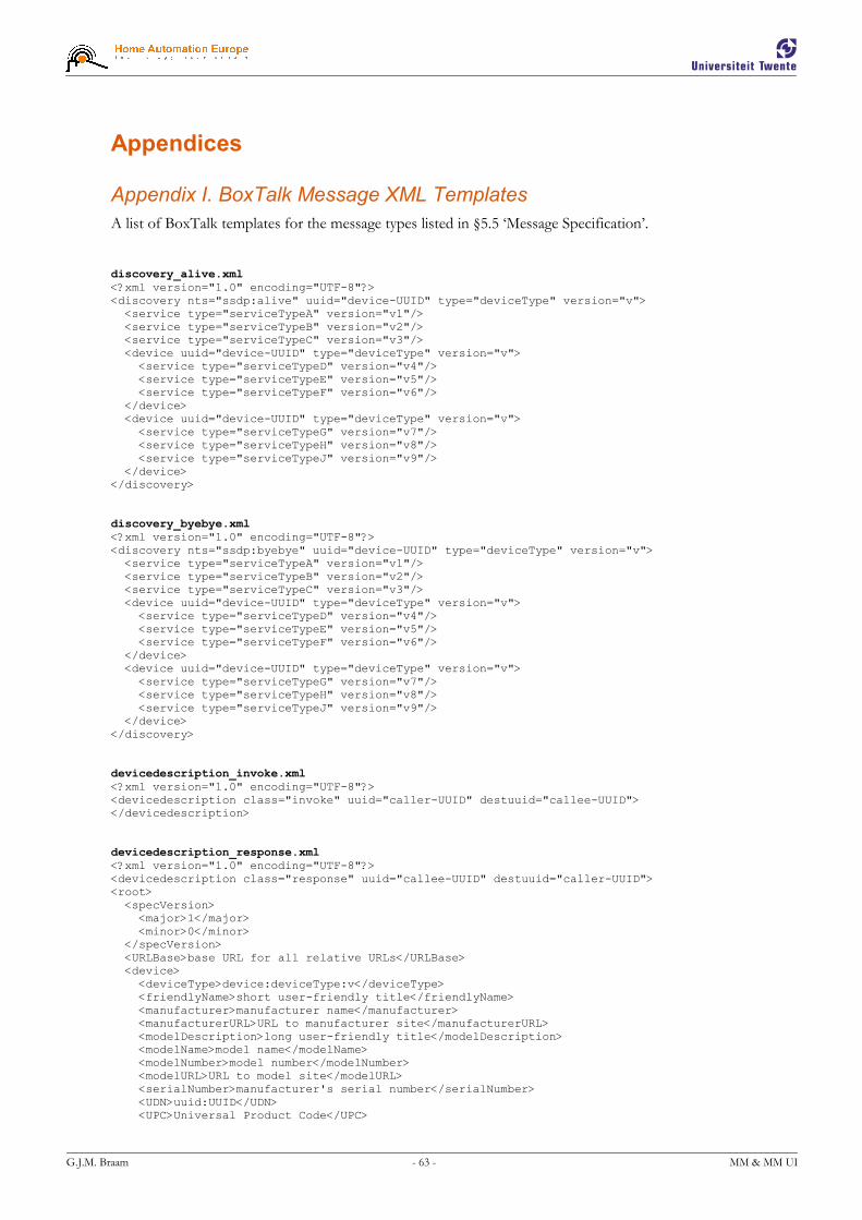
G.J.M. Braam - 63 - MM & MM UI
Appendices
Appendix I. BoxTalk Message XML Templates
A list of BoxTalk templates for the message types listed in §5.5 ‘Message Specification’.
discovery_alive.xml <?xml version="1.0" encoding="UTF-8"?> <discovery nts="ssdp:alive" uuid="device-UUID" type="deviceType" version="v"> <service type="serviceTypeA" version="v1"/> <service type="serviceTypeB" version="v2"/> <service type="serviceTypeC" version="v3"/> <device uuid="device-UUID" type="deviceType" version="v"> <service type="serviceTypeD" version="v4"/> <service type="serviceTypeE" version="v5"/> <service type="serviceTypeF" version="v6"/> </device> <device uuid="device-UUID" type="deviceType" version="v"> <service type="serviceTypeG" version="v7"/> <service type="serviceTypeH" version="v8"/> <service type="serviceTypeJ" version="v9"/> </device> </discovery> discovery_byebye.xml <?xml version="1.0" encoding="UTF-8"?> <discovery nts="ssdp:byebye" uuid="device-UUID" type="deviceType" version="v"> <service type="serviceTypeA" version="v1"/> <service type="serviceTypeB" version="v2"/> <service type="serviceTypeC" version="v3"/> <device uuid="device-UUID" type="deviceType" version="v"> <service type="serviceTypeD" version="v4"/> <service type="serviceTypeE" version="v5"/> <service type="serviceTypeF" version="v6"/> </device> <device uuid="device-UUID" type="deviceType" version="v"> <service type="serviceTypeG" version="v7"/> <service type="serviceTypeH" version="v8"/> <service type="serviceTypeJ" version="v9"/> </device> </discovery> devicedescription_invoke.xml <?xml version="1.0" encoding="UTF-8"?> <devicedescription class="invoke" uuid="caller-UUID" destuuid="callee-UUID"> </devicedescription> devicedescription_response.xml <?xml version="1.0" encoding="UTF-8"?> <devicedescription class="response" uuid="callee-UUID" destuuid="caller-UUID"> <root> <specVersion> <major>1</major> <minor>0</minor> </specVersion> <URLBase>base URL for all relative URLs</URLBase> <device> <deviceType>device:deviceType:v</deviceType> <friendlyName>short user-friendly title</friendlyName> <manufacturer>manufacturer name</manufacturer> <manufacturerURL>URL to manufacturer site</manufacturerURL> <modelDescription>long user-friendly title</modelDescription> <modelName>model name</modelName> <modelNumber>model number</modelNumber> <modelURL>URL to model site</modelURL> <serialNumber>manufacturer's serial number</serialNumber> <UDN>uuid:UUID</UDN> <UPC>Universal Product Code</UPC>
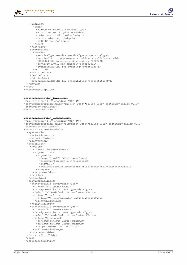
G.J.M. Braam - 64 - MM & MM UI
<iconList> <icon> <mimetype>image/format</mimetype> <width>horizontal pixels</width> <height>vertical pixels</height> <depth>color depth</depth> <url>URL to icon</url> </icon> </iconList> <serviceList> <service> <serviceType>service:serviceType:v</serviceType> <serviceId>urn:upnp-org:serviceId:serviceID</serviceId> <SCPDURL>URL to service description</SCPDURL> <controlURL>URL for control</controlURL> <eventSubURL>URL for eventing</eventSubURL> </service> </serviceList> <deviceList> </deviceList> <presentationURL>URL for presentation</presentationURL> </device> </root> </devicedescription> servicedescription_invoke.xml <?xml version="1.0" encoding="UTF-8"?> <servicedescription class="invoke" uuid="caller-UUID" destuuid="callee-UUID" serviceid="serviceID"> </servicedescription> servicedescription_response.xml <?xml version="1.0" encoding="UTF-8"?> <servicedescription class="response" uuid="callee-UUID" destuuid="caller-UUID" serviceid="serviceID"> <scpd xmlns="service-1-0"> <specVersion> <major>1</major> <minor>0</minor> </specVersion> <actionList> <action> <name>actionName</name> <argumentList> <argument> <name>formalParameterName</name> <direction>in xor out</direction> <retval /> <relatedStateVariable>stateVariableName</relatedStateVariable> </argument> </argumentList> </action> </actionList> <serviceStateTable> <stateVariable sendEvents="yes"> <name>variableName</name> <dataType>variable data type</dataType> <defaultValue>default value</defaultValue> <allowedValueList> <allowedValue>enumerated value</allowedValue> </allowedValueList> </stateVariable> <stateVariable sendEvents="yes"> <name>variableName</name> <dataType>variable data type</dataType> <defaultValue>default value</defaultValue> <allowedValueRange> <minimum>minimum value</minimum> <maximum>maximum value</maximum> <step>increment value</step> </allowedValueRange> </stateVariable> </serviceStateTable> </scpd> </servicedescription>

G.J.M. Braam - 65 - MM & MM UI
action_invoke.xml <?xml version="1.0" encoding="UTF-8"?> <action class="invoke" uuid="caller-UUID" destuuid="callee-UUID" serviceid="serviceID"> <u:actionName> <argumentName>in arg value</argumentName> </u:actionName> </action> action_response.xml <?xml version="1.0" encoding="UTF-8"?> <action class="response" uuid="callee-UUID" destuuid="caller-UUID" serviceid="serviceID"> <u:actionNameResponse> <argumentName>out arg value</argumentName> </u:actionNameResponse> </action> query_invoke.xml <?xml version="1.0" encoding="UTF-8"?> <query class="invoke" uuid="caller-UUID" destuuid="callee-UUID" serviceid="serviceID"> <u:QueryStateVariable> <u:varName>variableName</u:varName> </u:QueryStateVariable> </query> query_response.xml <?xml version="1.0" encoding="UTF-8"?> <query class="response" uuid="callee-UUID" destuuid="caller-UUID" serviceid="serviceID"> <u:QueryStateVariableResponse> <return>variable value</return> </u:QueryStateVariableResponse> </query> subscribe.xml <?xml version="1.0" encoding="UTF-8"?> <subscribe uuid="caller-UUID" destuuid="callee-UUID"> <target uuid="target-UUID" serviceid="serviceID"/> <target uuid="target-UUID" serviceid="serviceID"/> <target uuid="target-UUID" serviceid="serviceID"/> </subscribe> unsubscribe.xml <?xml version="1.0" encoding="UTF-8"?> <unsubscribe uuid="caller-UUID" destuuid="callee-UUID"> <target uuid="target-UUID" serviceid="serviceID"/> <target uuid="target-UUID" serviceid="serviceID"/> <target uuid="target-UUID" serviceid="serviceID"/> </unsubscribe> notify.xml <?xml version="1.0" encoding="UTF-8"?> <notify uuid="device-UUID" serviceid="serviceID"> <variableName>new value</variableName> </notify>
G.J.M. Braam - 66 - MM & MM UI
Appendix II. List of Built Software
A list of source software versions that I have built or tried to build for either investigation, development, debugging or testing purposes. Most of these where built for the ARM platform and packaged into IPKG for easy distribution using hcb-configure.
ali-0.4
alo-0.4
binutils-2.15
binutils-2.16.1
cherokee-0.4.29
crosstool-0.38
db-4.4.20
eaccelerator-0.9.4-rc1
expat-2.0.0
ezxml-0.8.6
fastdb-3.23
festival-1.95-beta
fnord-1.10
gcc-3.4.3
gd-2.0.33
gdb-5.3
gdbm-1.8.3
gigabase-3.44
glibc-2.3.2
indent-2.2.9
ipkg-utils-050831
iptstate-1.4
ixml-1.4.0
joe-3.3
kekedb-0.60
libiconv-1.9.1
libosip2-2.2.2
libpng-1.2.8
libupnp-1.3.1
libupnp-1.4.0
lighttpd-1.4.9
linux-2.6.11.2
lsof-4.77
lua-5.0.2
lua-5.1.1
lzo-2.02
minidb-2.1
mii-tool-1.9.1.1
monetdb-4.10.0
mysql-3.23.58
mysql-5.0.24a
ncurses-5.5
openldap-2.2.13
openssl-0.9.8a
openvpn-2.0.7
ortp-0.10.1
php-4.4.2
php-5.1.2
python-2.4.3
ripc-1.07
ruby-1.8.4
rsynth-2005.12.16
samba-3.0.21b
scm-5e1
screen-3.9.9
shore-interim-3
sox-12.17.9
sqlite-3.3.3
strace-4.5.14
subversion-1.3.2
termcap-1.3.1
turck-mmcache-2.4.6
valgrind-3.1.1
wb-1c1
zlib-1.2.2
zlib-1.2.3

G.J.M. Braam - 67 - MM & MM UI
Appendix III. HCB Technical Specifications
Hardware specifications � CPU: Cirrus Logic EP7312 @ 72 MHz, compliant with ARM version 5TE � Memory: 4 MB NOR boot flash, 64 MB SDRAM, 128 MB NAND flash � Altera EP1C3 FPGA � Real-time clock with battery back-up � ISO7816 interface, mini SIMM slot � Internal Xanura CTX15 module for A10/X10 traffic via power line � 230 VAC power input, euro connector � Switch to allow remote Internet access � 4 LEDs for status feedback � Analogue 14k4 modem and telephone connectors with DTMF generation and detection � 2 × 10/100 Mbit/s Ethernet, RJ-45 connectors � 1 × USB 1.1 connector � 4 × RS-232 connectors � 1 × RS-485 connector � 8 × general purpose digital inputs � 8 × general purpose digital outputs
Software specifications
Operating system
� GNU/Linux operating system, kernel version 2.6 � SSL and SSL-based VPN tunneling clients � Firewall detection � Digital certificate for identification � Supports NTP � DHCP server and client
Service center
� Heart-beat function � Remote management through internet possible � Extended logging possibilities � Messaging possibilities with SMS and E-mail
General specifications � Noise in full operation: 0 dB � MTBF: 90,000 hours � Energy consumption: < 5 W, 1 W in stand-by modus � No moving parts � Housing suited for mounting directly on wall and on DIN-rail. � Operating temperature 0 ºC to 40 ºC, humidity 5% to 95% � Production according to IPC-A-610A and ISO 9001:2000
Compliant with
� EN50065-1, 120 kHz +/- 2 kHz � EN60950-1 � 2002/95/EC � EN61000-6-3 � EN55022 CLASS A

G.J.M. Braam - 68 - MM & MM UI
Appendix IV. HCB Hardware Requirements
The HCB hardware requirements consist of an inventory of existing and near-future technologies that the HCB could and possibly will work with:
Connection Media � Ethernet LAN (home, wired, omni-directional, two way, minimal latency)
Generally the HCB will always be connected to the Service Center via a secure SSH tunnel over the internet. Also the HCB can service local clients on the LAN and/or WLAN both of which are al-ready present in many homes. This also means that media that are connected to the LAN or internet in general are implicitly supported. The connection media mentioned below that fall in this category are WLAN, GPRS and UMTS.
� WLAN (home, wireless, omni-directional, two way, minimal latency)
WLAN (IEEE 802.11x) is also generally available and often already present in many locations. Pro-vides an easy connection to the existing ethernet infrastructure to which an HCB is usually con-nected. Of the wireless protocols WLAN uses a relatively large amount of energy, more than Blue-tooth and Zigbee, so this drains battery usage on mobile devices noticeably.
� GPRS / UMTS (world, wireless, omni-directional, two way, medium latency)
General Packet Radio Service (GPRS, 2.5G) and Universal Mobile Telecommunications System (UMTS, 3G) can both deliver data streams to and from the HCB in real-time, by routing the com-munication through the permanent SSH tunnel to the HAE service center. Users can then operate clients that control the devices in your home directly and from all over the world. This connection medium is also a good candidate for connection handovers, as it could do exchanges with local sys-tems like Zigbee or WLAN when you enter or leave their local range.
� Infrared (room, wireless, directional, one way, minimal latency)
Infrared is used in remotes that control many in-home appliances like televisions and stereo sets. These remotes could also be used to send commands to the HCB. Receiving is impossible with stan-dard remote control devices because they communicate only one way and usually have no way to dis-play the received content. Also you would need to install infrared modules in each room that you want to use a remote in.
� Bluetooth (room, wireless, omni-directional, two way, minimal latency)
Bluetooth (IEEE 802.15.1) is widely available, but the range is only about 10 meters using the class 3 low-energy version of the protocol (the most commonly used one), which would require transmitters in each room. Also needed would be another form of data transport to communicate the information between the HCB and the actual Bluetooth transmitters.
� DECT (home, wireless, omni-directional, two way, minimal latency)
Digital Enhanced Cordless Telecommunications (DECT) technology is widely used but is losing ground to more modern IP-based solutions like Voice over IP. Support is currently present using a separate DECT base station that converts the digital signal to an analog DTMF signal, which can then be intercepted by the HCB using DTMF as described below. The hardware, which is very ex-pensive, is not and will not be present on HCB.
� DTMF (world, wired, omni-directional, two way, minimal latency)
Dial Tone Modulated Frequency (DTMF) can be used to send commands using your own phone over the Plain Old Telephone System (POTS) and a voice menu on the HCB. Hardware support is currently present on the HCB by routing the signal connecting your phone through the Digital Signal Processor (DSP) that detects the different DTMF frequencies.

G.J.M. Braam - 69 - MM & MM UI
� SMS (world, wireless, omni-directional, two way, medium latency)
Short Message Service (SMS) allows relatively simple commands to be sent to the HCB like ‘turn on heating tomorrow’ if you arrive home from vacation one day early, or ‘turn on garden sprinklers to-night’ after a very dry period.
The SMS message would be sent to an HAE specific number, which would be routed to the HAE Service Center and in turn figure out the calling number and send a command to the correct HCB configuration accordingly, possibly requiring inclusion of some kind of authentication token in the message. Acknowledgement messages will be sent after the command has been processed and sent to the HCB of the operator.
� E-mail (world, wireless, omni-directional, two way, high latency)
An e-mail message would follow roughly the same path as an SMS message, with the exception that a mail message can possibly take a lot longer to be delivered because of the way that the common e-mail transfer infrastructure is designed. With e-mails also more complex messages could be sent, be-cause they do not have a built in 160 character limit per message like SMS.
� A10/X10 (home, wired+wireless, omni-directional, two way, medium latency)
A10, an Eaton-Holec specific extension to the public X10 standard, is a bus-based communication system using the (existing) electric power line infrastructure for communication. It uses 16 letter-codes with 16 numbers each for a total of 256 possible addresses. Multiple sensors/actors can be programmed to send/respond to the same address range. A wide range of switches, dimmers and controllable actors are commercially available on the market today, of which the DAIX10 depicted in Figure 2-b is an example.
� Konnex (home, wired, omni-directional, two way, minimal latency)
Konnex (EN 50090) is a bus-based communication system using 1-on-1 routing of electric wiring from each device to the central power distribution point. Each device is uniquely identifiable and can be programmed to locally run small scriptlets. Formerly known as European Installation Bus (EIB), KNX is the world's leading system for ‘intelligent’ electrical installation networking. Konnex is mainly used during initial construction of larger office complexes.
� Zigbee (home, wireless, omni-directional, two way, minimal latency)
Zigbee (IEEE 802.15.4) is a wireless communication system between devices that uses a mesh-like structure for retransmission and message passing to ensure the lowest power consumption possible for the connected devices. It has incorporated security and network separation. In the future special zigbee connectors could be developed for PDAs so it could be used to deliver network connectivity at minimal energy costs.
� Visonic (home, wireless, omni-directional, one way, minimal latency)
Visonic is a manufacturer of home and commercial security alarm systems, detectors, access control and accessories. Communication takes place over radio frequency and is typically in one direction only: from a security device to a control unit. Most devices provide special signals for low-battery and signal jamming situations, which can be received centrally from the control unit.
� Honeywell (home, wired+wireless, omni-directional, two way, minimal latency)
Honeywell is a major multinational corporation that produces electronic control systems and automa-tion equipment. It is a major supplier of engineering services and avionics for NASA, Boeing, Airbus and the United States Department of Defense. Although best known for their thermostats, Honey-well also has products in generic home automation, remote control, air purification and air condition-ing. Their products communicate using the Networked Appliance Protocol.
Of these connection media the wired version of the A10/X10 protocol will be among the first to be supported, since hardware support for it is built directly into the HCB itself. Next will probably be Vi-sonic, since a HAE has abundant experience with its use and installation.

G.J.M. Braam - 70 - MM & MM UI
Devices
� Regular PC
PCs and laptops will primarily be used during the initial configuration of an HCB, using a web browser as a thin, server-oriented client. Later user interfaces for daily use that run on a web browser will also be developed. Communication with the HCB will generally be via wired ethernet or WLAN. There is a special service port present on the front of the HCB for easy connection with a laptop dur-ing the installation process using an UTP cable.
� Touch Screen / Tablet PC
These types of devices will probably only be used for daily use, other than that it is mostly identical to the properties described for a Regular PC. The user interface will most likely run on a web browser in full screen mode or as a dedicated full screen Macromedia Flash or Java application.
� PocketPC
A client running on a PocketPC will only be used for daily use, because it does not have enough screen real estate for the full configuration interface. A test version of this client is built with Macro-media Flash and runs as a dedicated application on the Windows Mobile OS using an XML as a data source for the home layout. For communication it can use any of the technologies available on Pock-etPCs, including WLAN and Bluetooth.
� PalmOS
For PalmOS flash support is also available. PalmOS is however losing territory over Windows Mobile and SymbianOS on the market, so development of a client for it currently has a low priority. PalmOS devices can make use of WLAN and Bluetooth for communication with the HCB.
� DTMF Phones
Regular phones that can produce DTMF tones can connect to the HCB via a regular phone line. A Digital Signal Processor is connected to the internal modem chip on the PCB, so sound samples can be played over the line. DTMF tones can be detected and used to control a voice menu. The HCB can also make calls autonomously in case of alarm or other critical situations that need decisions to be made by the home owner.
� DECT Phones
Direct support for DECT communication in the form of an onboard chip or dedicated hardware is not very likely. The DECT standard is losing popularity and is gradually being replaced by WLAN and Voice over IP. DECT phones can be supported via a detour as mentioned above under the heading ‘DECT’ in the section ‘Connection Media’ of this appendix.
� SymbianOS Phones
SymbianOS phones can easily be supported because it has support for java MIDP. Possibly native applications could be created, but you will need to make a special version for each phone platform (Series 60v1, 60v2, 60v3, 80 & 90, UIQ2 and UIQ3) with each a wide range of screen resolutions on as many different devices. Possible communication media on these platforms are identical to those described under the Java client in §2.2 ‘Client Types’.
� Regular Remote Controls
Normal remote controls can be used to send commands to the HCB by using commercially available Infrared sensors. As discussed under the heading ‘Infrared in the section ‘Connection Media’ of this appendix this would mean that each room will need its own IR sensor. Also ‘normal’ remote controls have buttons with standard labels that are not applicable to home automation. Possible solutions are using a more advanced LCD remote for which you can make user interface screens and specific commands like the Philips Pronto [PRO]. These special remotes sometimes also often support some kind of RF communication, solving the Infrared sensors problem.

G.J.M. Braam - 71 - MM & MM UI
� Game Consoles
Game consoles are found in a lot of homes nowadays. Enabling them to control the HCB is consid-ered as a possibility, if the client software can be installed without too many problems. Both also have support for ethernet connections tying them into the LAN. Regrettably these consoles often do not allow you to run arbitrary programs that are not officially supported by the console company and of-ficial software development kits are not cheap. Consoles under consideration are Microsoft’s X-Box and the Sony Playstation series.
� Portable Game Consoles
Portable variations of the game consoles like the Sony PSP or the Nintendo DS have standard sup-port for WLAN and are therefore prime candidates as HCB control devices. However, the same thing goes as for the non-portable consoles: unapproved software installation is not trivial, so some investigation is needed if it is worth the trouble to develop software for these devices, either officially or unofficially.
� Home Automation Components
This category includes all device components used for home automation that are commercially avail-able and are interconnected by some sort of publicly accepted standard. Examples of these are A10/X10, Konnex (EIB) and newcomer Zigbee. Most of these systems have varying degrees of intel-ligence and configurability built into their hardware. X10 can for example send an All Lights Off command to which multiple devices can respond, while Konnex and Zigbee have small programs that can execute locally on the hardware.
The HCB will be able to link with these communication channels to send and receive these com-mands through interface hardware. Some of this hardware will eventually be integrated on the Printed Circuit Board (PCB) like A10/X10 already is. Device drivers will be designed to deliver a uniform in-terface from the connected devices to the rest of the HCB software.
� Other Hardware
The HCB has 8 digital inputs, 4 digital outputs and 4 relay outputs. Furthermore it has a USB port, 4 serial ports and an RS-485 port to communicate with external devices. These channels allow an instal-lation engineer to physically connect supported custom hardware like for example sensors for energy, gas and water and use their data in the standard HCB configuration application if they are supported by the basic HCB core software. New software drivers will constantly be developed as new commer-cial hardware becomes available on the market.
� Set-Top Box
Currently negotiations are underway for support of a media player set-top box which will be con-nected to a television set. The features of this device are pretty basic, so probably it will run a light-weight full-screen web browser displaying HCB-served web pages for daily use. HCB Configuration on this device will probably not be practical, since it will not have a keyboard for data entry, just a remote.