Embed Size (px)
Citation preview

1
Supporting information for
Revisiting water sorption isotherm of MOF using
electrical measurements Shyamapada Nandi,a Himanshu Aggarwal,b,c Mohammad Wahiduzzaman,a Youssef
Belmabkhout,b Guillaume Maurin,a Mohamed Eddaoudi,b Sabine Devautour-Vinota aInstitut Charles Gerhardt Montpellier, UMR 5253 CNRS, UM, ENSCM Université Montpellier,
Place E. Bataillon, 34095 Montpellier cedex 5, France. bKing Abdullah University of Science and Technology, Division of Physical Sciences and
Engineering, Advanced Membranes & Porous Materials Center, Functional Materials Design,
Discovery & Development Research Group, Thuwal 23955-6900, Kingdom of Saudi Arabia cBirla Institute of Technology and Science-Pilani, Hyderabad Campus, Jawahar Nagar, Shamirpet,
Hyderabad, India.
1. Synthesis p 2
2. X-Ray Powder Diffraction p 3
3. N2 Adsorption Isotherm p 4
3. Conductivity p 5
4. Water Sorption Isotherm p 11
5. Modelling p 12
Electronic Supplementary Material (ESI) for Chemical Communications.This journal is © The Royal Society of Chemistry 2019

2
1. Synthesis
All the chemicals were bought from Sigma Aldrich and used without further purification.
Synthesis of Cr-soc-MOF-1:
A solution of FeCl3·6H2O in DMF (0.1 M, 0.3 mL, 0.03 mmol) was prepared and added to a mixture
of H4TCPT (7.1 mg, 0.01 mmol), DMF (1 mL), and acetonitrile (1 mL) in a 20 mL scintillation vial.
A dilute nitric acid solution in DMF (3.5 M, 1.5 mL) was prepared separately and added to the
reaction mixture. The clear orange-yellow solution was then placed in a preheated oven at 115 °C for
3 days to obtain square block shaped orange-yellow shaped. The crystals were subsequently
washed with fresh DMF and the DMF was replaced every 4-5 hours. After washing the crystals with
DMF for 24 hours, the crystals were immersed in acetone and thrice daily over a period of 3 days.1
The sample was activated by heating at 393 K for 8 hrs under dynamic vacuum.
Figure S1. Schematic representation of in Cr-soc-MOF-1 in which yellow spheres are representing
the cubic cages and the blue lines are showing the interconnected channels. Color code: C, gray; O,
red; Cl, green; Cr, blue, H, white.

3
2. X-Ray Powder Diffraction data
Powder XRD patterns of the solids before and after conductivity measurements were collected on a
PANalytical X'Pert equipped with an X'Celerator detector and using a wavelength, λ =1.5406 Å with
an operating voltage of 40 kV and a beam current of 30 mA.
Figure S2. Simulated (green) and experimental XRPD patterns of Cr-soc-MOF-1 before (red) and
after (blue) impedance measurements.
5 10 15 20 25 30 35 40
rela
tive
Inte
nsity
2-Theta (deg)

4
3. N2 Adsorption Isotherm
N2 adsorption isotherms were collected on the activated solid at 77 K using a Quadrasorb evo -
Quantachrome Instrument.
FigureS3.N2sorptionisothermofCr-soc-MOF1recordedat77K.
Thecorrespondingporevolumeis2.1cm3.g-1andtheBETarea is4540m2.g-1,whichmatchesvery
wellwiththepreviouslyreporteddata1,aswellaswiththecalculatedvaluesdeducedfromthefully
geo-optimizedsolid(cfmodellingpart:Vporevolume=2.1cm3.g-1andSBET=4665m2.g-1).
0.0 0.1 0.2 0.3 0.4 0.5 0.6 0.7 0.8 0.9 1.0
200
400
600
800
1000
1200
1400
AdsorptionDesorption
Upt
ake
(cm
3 /g)
Relative Pressure (P/P0)

5
4. Conductivity
The humidity dependant impedance measurements were carried out using a solartron (Ametek)
impedance analyzer over a frequency range from 1Hz to 1 MHz with an applied voltage of 1 V. The
powder sample of Cr-soc-MOF-1 was placed between two gold electrodes in a parallel plate capacitor
configuration with an annular Teflon spacer to provide insulation, allowing the use of the “two-probe”
method for the electrical measurements. The relative humidity and temperature were controlled by a
‘Bench-Top Type Temperature and Humidity Chamber’ form ESPEC Corporation. It is composed by
a small liquid water “bath” located in the mixing plenum; as the chamber air is drawn into the plenum,
it passes the bath, picking up vapor submitted to the sample. To establish the electrical isotherms,
impedance data were recorded upon increasing (adsorption) and decreasing (desorption) the Relative
Humidity (RH) at 298 K and 363 K. The sample was equilibrated for at least 12 hours, before
changing the RH/T conditions, even the equilibration time can be shortened to 1.5 hour, as evidenced
in Figure S4.
The resistance R of the solids was deduced from the analysis of the Nyquist plots (-Z” = f(Z’)), that is
from the semi-circle extrapolation to the real-axis, while the corresponding conductivity values s
were obtained using σ=1/R×l/S, where l and S are the sample thickness and area respectively.
In the Bode representation (σ’ac = f(F)), the real part of the ac conductivity, σ’ac (ω,T), usually results
from the combination of three contributions: σ’ac (ω,T) = σ’MWS (ω,T) + σdc (T) + σ’(ω,T). The
polarization component σ’(ω,T), corresponding to the increasing part of the signal, arises from the
local rearrangement of charges or dipoles causing dipolar reorientation. The dc conductivity plateau
σdc (T) results from the long-range redistribution of charges. In case of highly conductive materials,
the Maxwell Wagner Sillars contribution σ’MWS (ω,T) due to the charge accumulation to the
sample/electrode interface is observed at low frequency. The absence of the dc plateau in the Bode
representation for the anhydrous solid relates with the insulating behaviour of Cr-soc-MOF-1 in the
whole domain of explored temperatures and further evidence that a guest mediator is required to allow
the proton transfer throughout the porosity of the solid.

6
Figure S4. Nyquist plot from ac impedance data for the Cr-soc-MOF-1 recorded at 363 K under 70%
RH after 12 (black) and 24 (red) hours of equilibration.
Figure S5. Time evolution of the conductivity of Cr-soc-MOF-1 recorded at 363 K under 70% RH.
The conductivity recorded at 90°C/70%RH converges towards a steadily value for 1,5 hrs of
equilibrium.
0 5 10 15 20 25-7
-6
-5
-4
t (Hour)
log
(s /
S cm
-1)

7
Figure S6. Nyquist plots from ac impedance data for the Cr-soc-MOF-1 recorded at 298 K under (a)
35% RH (black), 40% RH (red), 50% RH (green), 55% RH (blue) and (b) 60% RH (cyan), 65% RH
(magenta), 70% RH (wine), 80% RH (olive) and 90% RH (orange) upon increasing RH.
Figure S7. Nyquist plots from ac impedance data for the Cr-soc-MOF-1 recorded at 298 K under (a)
35% RH and (b) 80% RH (olive), 70% RH (wine), 65% RH (magenta), 60% RH (cyan), 55% RH
(blue), 50% RH (green), 45% RH (dark yellow) and 40% RH (red) upon decreasing RH.

8
Figure S8. Nyquist plots from ac impedance data for the Cr-soc-MOF-1 recorded at 363 K under (a)
30% RH (black), 40% RH (red), 50% RH (green) 55% RH (blue) and (b) 60% RH (cyan), 70% RH
(magenta), 80% RH (wine) and 90% RH (olive) upon increasing RH.
Figure S9. Nyquist plots from ac impedance data for the Cr-soc-MOF-1 recorded at 363 K under (a)
30% RH (black), 40% RH (red), 45% RH (dark yellow), 50% RH (green), 55% RH (blue) and (b)
60% RH (cyan), 70% RH (magenta) and 80% RH (wine) upon decreasing RH.

9
Table S1. Conductivity values recorded at 298 K and 363 K for the Cr-soc-MOF-1 upon increasing
and decreasing RH.
Adsorption branch T = 298 K Desorption branch T = 298 K
RH %
σ Scm-1
RH %
σ Scm-1
35 2.4 ˣ 10-8 35 2.7 ˣ 10-8 40 2.7 ˣ 10-8 40 6.1 ˣ 10-7 50 4.0 ˣ 10-8 45 9.7 ˣ 10-7 55 5.7 ˣ 10-8 50 1.1 ˣ 10-6 60 7.0 ˣ 10-7 55 1.2 ˣ 10-6 65 1.6 ˣ 10-6 60 1.5 ˣ 10-6 70 1.6 ˣ 10-6 65 1.6 ˣ 10-6 80 2.6 ˣ 10-6 70 2.0 ˣ 10-6 90 5.1 ˣ 10-6 80 3.3 ˣ 10-6
Adsorption branch T = 363 K Desorption branch T = 363 K
30 1.8 ˣ 10-7 30 1.8 ˣ 10-7 40 1.9 ˣ 10-7 40 2.8 ˣ 10-7 50 2.1 ˣ 10-7 45 3.5 ˣ 10-7 55 1.6 ˣ 10-6 50 5.9 ˣ 10-7 60 1.0 ˣ 10-5 55 2.2 ˣ 10-6 70 1.7 ˣ 10-5 60 1.2 ˣ 10-5 80 2.8 ˣ 10-5 70 2.2 ˣ 10-5 90 5.0 ˣ 10-5 80 2.8 ˣ 10-5
Figure S10. Arrhenius plot of the conductivity for Cr-soc-MOF-1 under 40% RH (blue square) and
80% (red triangle) of RH. The lines correspond to the linear least-square fit.
2,7 2,8 2,9 3,0 3,1 3,2 3,3
-12
-10
-8
-6
-4
ln (s
T/ S
K c
m-1
)
1000/T (K-1)
DE = 0.37 eV
DE = 0.33 eV

10
Figure S11. Sigmoidal curve fitting (solid line) of the “electrical” water adsorption (a-solid spheres)
and desorption (b-empty circles) isotherms for Cr-soc-MOF-1 at 298 K obtained by impedance
spectroscopy.
Figure S12. Sigmoidal curve fitting (solid line) of the “electrical” water adsorption (a-solid spheres)
and desorption (b-empty circles) isotherms for Cr-soc-MOF-1 at 363 K obtained by impedance
spectroscopy.
Table S2. α parameters deduced from the adsorption and desorption branches for the volumetric and
electrical isotherms. α corresponds to the RH value at which half of the total water capacity is
achieved.
Adsorption Isotherm T (K)
a (adsorption branch)
a (desorption branch)
Volumetric Measurements
298 61 52 363 65 62
Electrical Measurements
298 58 38 363 56 55
20 30 40 50 60 70 80 90-8,5
-8,0
-7,5
-7,0
-6,5
-6,0
-5,5
-5,0
-4,5
Log
(s/S
cm-1
)
RH %20 30 40 50 60 70 80 90
-8,5
-8,0
-7,5
-7,0
-6,5
-6,0
-5,5
-5,0
-4,5Lo
g (s
/Scm
-1)
RH %
a) b)
20 30 40 50 60 70 80 90-7,5
-7,0
-6,5
-6,0
-5,5
-5,0
-4,5
-4,0
-3,5
Log
(s/S
cm-1
)
RH %20 30 40 50 60 70 80 90
-7,5
-7,0
-6,5
-6,0
-5,5
-5,0
-4,5
-4,0
-3,5
Log
(s/S
cm-1
)
RH %
a) b)

11
5. Water Sorption Isotherm
The as-synthesized Cr-soc-MOF-1 crystals were treated with volatile solvents and heated prior to
water vapor sorption experiments. As a common strategy crystals were exchanged acetone for 4-5
days, during which time the solvent was replaced 3-4 times per day. The crystals were then dried by
heating under vacuum at 393 K or 8 h to yield activated samples. Temperature was increased to desire
value from room temperature at the rate of 1 K min-1. Activated sample was used for corresponding
isotherm measurement. Sorption data was processed by using Helmholtz equation. The adsorption
isotherms were recorded at three different temperatures 298 K and 363 K.
A volumetric apparatus Vstar1 vapor sorption analyzer from Quantachrome instruments was used for
collecting water adsorption isotherms at different temperatures. Schematic diagram of the instrument
is shown in the scheme S1, from the screenshot of the software window.
Scheme S1. Schematic representation of V-Star vapor sorption instrument.
12
6. Modelling
DFT calculations
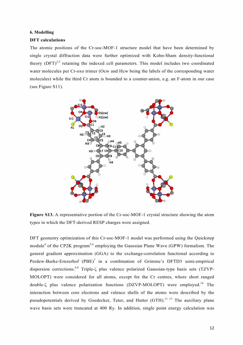
The atomic positions of the Cr-soc-MOF-1 structure model that have been determined by
single crystal diffraction data were further optimized with Kohn-Sham density-functional
theory (DFT)2,3 retaining the indexed cell parameters. This model includes two coordinated
water molecules per Cr-oxo trimer (Ocw and Hcw being the labels of the corresponding water
molecules) while the third Cr atom is bounded to a counter-anion, e.g. an F-atom in our case
(see Figure S11).
Figure S13. A representative portion of the Cr-soc-MOF-1 crystal structure showing the atom
types in which the DFT-derived RESP charges were assigned.
DFT geometry optimization of this Cr-soc-MOF-1 model was performed using the Quickstep
module4 of the CP2K program5,6 employing the Gaussian Plane Wave (GPW) formalism. The
general gradient approximation (GGA) to the exchange-correlation functional according to
Perdew-Burke-Ernzerhof (PBE)7 in a combination of Grimme’s DFTD3 semi-empirical
dispersion corrections.8,9 Triple-ζ plus valence polarized Gaussian-type basis sets (TZVP-
MOLOPT) were considered for all atoms, except for the Cr centres, where short ranged
double-ζ plus valence polarization functions (DZVP-MOLOPT) were employed.10 The
interaction between core electrons and valence shells of the atoms were described by the
pseudopotentials derived by Goedecker, Teter, and Hutter (GTH).11–13 The auxiliary plane
wave basis sets were truncated at 400 Ry. In addition, single point energy calculation was

13
performed to extract the atomic partial charges of Cr-soc-MOF-1 crystal applying the
REPEAT fitting method14 for the periodic system as implemented in the CP2K code.
Table S3: LJ potential parameters and partial charges of the atom types of Cr-soc-MOF-1
crystal structure.
Atom Type ε/kB [K] σ [Å] q (e–) 1 H1(Hcw) 0.0000 2.8460 0.377 2 H2 7.6490 2.8460 0.178 3 H3 7.6490 2.8460 0.130 4 H4 7.6490 2.8460 0.105 5 H5 7.6490 2.8460 0.121 6 H6 7.6490 2.8460 0.135 7 C1 47.8570 3.4730 0.593 8 C2 47.8570 3.4730 0.098 9 C3 47.8570 3.4730 -0.232 10 C4 47.8570 3.4730 -0.149 11 C5 47.8570 3.4730 0.144 12 C6 47.8570 3.4730 -0.036 13 C7 47.8570 3.4730 -0.105 14 C8 47.8570 3.4730 -0.151 15 C9 47.8570 3.4730 0.026 16 C10 47.8570 3.4730 0.106 17 C11 47.8570 3.4730 -0.175 18 O1(Ocw) 30.1940 3.1180 -0.719 19 O2 30.1940 3.1180 -0.553 20 O3 30.1940 3.1180 -0.632 21 O4 30.1940 3.1180 -1.081 22 F1 36.4830 3.0930 -0.532 23 Cr1 7.5480 2.6930 1.479 24 Cr2 7.5480 2.6930 1.719

14
Pore size distribution (PSD):
The geometric methodology reported by Gelb and Gubbins15 was used to calculate the pore size
distributions (PSD) of the geometry optimized structures, as depicted in Figure S12. In this
calculation, the van der Waals parameters of the framework atoms were adopted from Universal Force
Field (UFF).16 It is shown that this MOF shows at least two distinct distribution peaks at ~11.5 Å and
~15 Å associated to the cubic cages formed by surrounded larger pore channel.
Figure S14: Pore size distribution of Cr-soc-MOF-1 calculated from the DFT optimized
geometry of the solid.
15
NVT-MC simulations:
The DFT geometry optimized model of Cr-soc-MOF-1 was further employed in Monte Carlo
(MC) calculations in the NVT ensemble loaded with the amounts of water molecules deduced
from the experimental adsorption isotherms collected at T = 298 K and 363 K to determine the
local arrangement of the adsorbed water molecules with the MOF at 298 K and 363 K using
the Complex Adsorption and Diffusion Simulation Suite (CADSS) code.17. We considered a
simulation box of 1 unit cell of Cr-soc-MOF-1 maintaining atoms at their initial positions. The
water molecules were described by the TIP4P/2005 potential model corresponding to a
microscopic representation of four LJ sites (see Supporting Table S4).18 The interactions
between the adsorbed water molecules and the MOF structure were described by a
combination of site-to-site Lennard-Jones (LJ) contributions and Coulombic terms. A mixed
set of the universal force field (UFF)16 and DREIDING force field19 parameters were adopted
to describe the LJ parameters for the atoms in the inorganic and organic part of the framework,
respectively (see Supporting Table S3). However, following the treatment adopted in other
well-known force fields,20,21 the hydrogen atoms of the water molecules coordinated to the Cr
atoms of the IBUs are allowed to interact with the adsorbate water molecules via the
coulombic potential only as justified in previous studies on similar Al-based MOF
topologies.22 Short-range dispersion forces were truncated at a cut-off radius of 12 Å while the
interactions between unlike force field centers were treated by means of the Lorentz-Berthelot
combination rule. The long-range electrostatic interactions were handled using the Ewald
summation technique. For each NVT simulations, a typical 2×10⁸ MC steps for equilibration
and 2×10⁸ MC steps have been used for production runs. Additionally, in order to gain insight
into the configurational distributions of the adsorbed species in Cr-soc-MOF-1, additional data
were calculated for different water loading determined at different relative pressure from the
experimental volumetric adsorption isotherm, including the hydrogen bond networks and the
radial distribution functions (RDF) for the intermolecular atomic pairs of the adsorbed water
and the MOF.
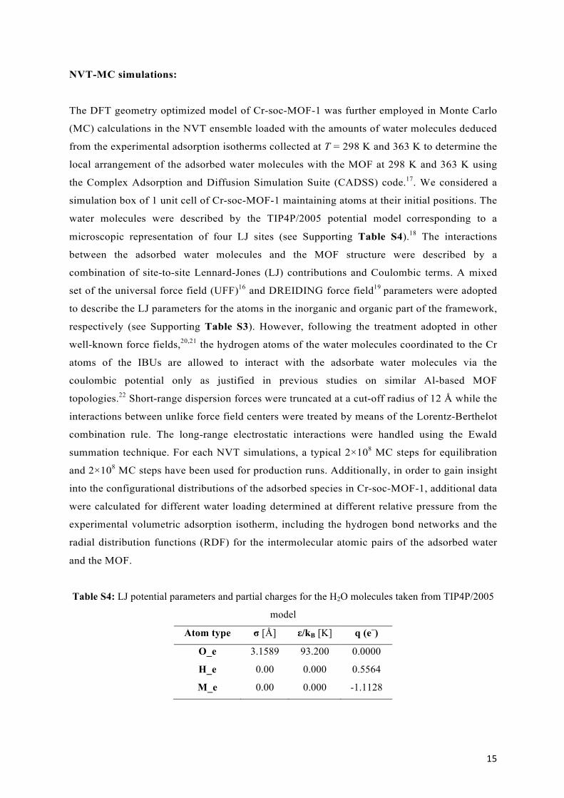
Table S4: LJ potential parameters and partial charges for the H2O molecules taken from TIP4P/2005
model
Atom type σ [Å] ε/kB [K] q (e–)
O_e 3.1589 93.200 0.0000
H_e 0.00 0.000 0.5564
M_e 0.00 0.000 -1.1128

16
Hydrogen bond definition:
The detection of hydrogen bonds was conducted by assuming the following criteria: (i)
distance between donor and acceptor oxygen centers (D−A) is shorter than 3.5 Å, and (ii) the
corresponding D-H-A angle — formed by the intramolecular O−H vector of the donor
molecule, and the intermolecular H−O vector of donor and acceptor molecules — is greater
than 140°. The average number of hydrogen-bonds per H2O was calculated from seven
representative configurations taken from the MC production runs, and thereby few fluctuating
data points appeared in the statistics.
Figure S15: Radial distribution functions (RDFs) of Ow···Ow (solid lines) and cumulative number of
water molecules as a function of the distance (dashed lines) calculated for the identical number
density of adsorbed water molecules (n = 29 per unit cell) inside the MOF pore corresponding to the
adsorbed water content at RH = 24.5% and 25.7 % at T = 298 K and 363 K, respectively.
Figure S16: Radial distribution functions (RDFs) of O-O and O-H calculated from the MC-NVT
simulations for different relative pressures at T = 298 K.

17
Figure S17: Radial distribution functions (RDFs) of X-OW (a) and X-HW (b) calculated from the MC-
NVT simulations at T = 298 K and T = 363 K, with X = halogen.

18
References:
1 S. M. Towsif Abtab, D. Alezi, P. M. Bhatt, A. Shkurenko, Y. Belmabkhout, H. Aggarwal, Ł. J.
Weseliński, N. Alsadun, U. Samin, M. N. Hedhili and M. Eddaoudi, Chem, 2018, 4, 94–105.
2 P. Hohenberg and W. Kohn, Phys. Rev., 1964, 136, B864–B871.
3 W. Kohn and L. J. Sham, Phys. Rev., 1965, 140, A1133–A1138.
4 J. VandeVondele, M. Krack, F. Mohamed, M. Parrinello, T. Chassaing and J. Hutter, Comput.
Phys. Commun., 2005, 167, 103–128.
5 J. Hutter, M. Iannuzzi, F. Schiffmann and J. VandeVondele, Wiley Interdiscip. Rev. Comput.
Mol. Sci., 2014, 4, 15–25.
6 The CP2K developers group, http://www.cp2k.org, (accessed 10 February 2019).
7 J. P. Perdew, K. Burke and M. Ernzerhof, Phys. Rev. Lett., 1996, 77, 3865–3868.
8 S. Grimme, J. Antony, S. Ehrlich and H. Krieg, J. Chem. Phys., 2010, 132, 154104.
9 S. Grimme, J. Comput. Chem., 2004, 25, 1463–73.
10 J. VandeVondele and J. Hutter, J. Chem. Phys., 2007, 127, 114105.
11 S. Goedecker, M. Teter and J. Hutter, Phys. Rev. B, 1996, 54, 1703–1710.
12 M. Krack, Theor. Chem. Acc., 2005, 114, 145–152.
13 C. Hartwigsen, S. Goedecker and J. Hutter, Phys. Rev. B, 1998, 58, 3641–3662.
14 C. Campañá, B. Mussard and T. K. Woo, J. Chem. Theory Comput., 2009, 5, 2866–2878.
15 L. D. Gelb and K. E. Gubbins, Langmuir, 1999, 15, 305–308.
16 A. K. Rappe, C. J. Casewit, K. S. Colwell, W. A. Goddard and W. M. Skiff, J. Am. Chem.
Soc., 1992, 114, 10024–10035.
17 Q. Yang and C. Zhong, J. Phys. Chem. B, 2006, 110, 655–8.
18 J. L. F. Abascal and C. Vega, J. Chem. Phys., 2005, 123, 234505.
19 S. L. Mayo, B. D. Olafson and W. A. Goddard, J. Phys. Chem., 1990, 94, 8897–8909.
20 W. L. Jorgensen, D. S. Maxwell and J. Tirado-Rives, J. Am. Chem. Soc., 1996, 118, 11225–
11236.
21 C. D. Wick, J. M. Stubbs, N. Rai and J. I. Siepmann, J. Phys. Chem. B, 2005, 109, 18974–
18982.
22 A. Cadiau, J. S. Lee, D. Damasceno Borges, P. Fabry, T. Devic, M. T. Wharmby, C.
Martineau, D. Foucher, F. Taulelle, C. H. Jun, Y. K. Hwang, N. Stock, M. F. De Lange, F.
Kapteijn, J. Gascon, G. Maurin, J. S. Chang and C. Serre, Adv. Mater., 2015, 27, 4775–4780.