Embed Size (px)
Citation preview
Supporting InformationBarish et al. 10.1073/pnas.0808736106SI TextDNA Sequence Design. The design of the ‘‘tall rectangle’’ DNAorigami is detailed in literature (1); it is composed of a 7,249-baselong scaffold strand (single-stranded M13mp18; New EnglandBiolabs) and 224 short (32-base) staple strands. Here, only 192of the original staple strands were used. Sixteen strands along theleft side of the origami were omitted so that the disordered loopsof scaffold that remain prevent stacking interactions betweenorigami. Another 16 strands along the right side were omitted toleave sites for the binding of tile adapter strands. All tile adapterstrands and tile strands were designed using programs written inMATLAB, available at: www.dna.caltech.edu/DNAdesign/.These sequences were optimized to minimize the degree ofcomplementarity between subsequences that are not intended tohybridize. Sticky-end sequences were designed to have similarhybridization energies. All strand sequences used in this study,including the tall rectangle origami staples that are identical tothe original design (1), are listed in the SI Appendix.
Sample Preparation. Except for the scaffold strand and the 192staple strands, all oligos were PAGE purified (Integrated DNATechnologies). The concentration of the scaffold strand was10 nM, the staple strands 50 nM, and tile adapter strands 100 nM,except in the case of some binary counter experiments in whichthe scaffold concentration was 5 nM. (With 5–10 nM seedconcentrations, seeded ribbons attached to origami were typi-cally 0.5–1 �m long. In experiments not shown here, by decreas-ing the scaffold concentration to 1 nM, ribbons 5 �m long couldoften be observed.) Tile, tile adapter, and scaffold strands werequantitated with a UV spectrophotometer (Biophotometer;Eppendorf), whereas the concentration of staple strands wereassumed to be that quoted by the manufacturer, without furtherquantitation. Concentrations of quantitated strands were ad-justed to be within 10% of that intended and, based on previousexperience, we expect the concentrations of staple strands to fallwithin �10% of that intended. Note that it is not important thatthe concentration of the staple strands be accurate; origamifolding is highly insensitive to the relative concentrations ofstaple strands as long as there is a few-fold excess of each staplestrand over the scaffold (1). For the Variable-Width and Copyexperiments all tile strand concentrations were 100 nM exceptfor the strands in the repeatable (0/1)-blocks. Variable-Widthexperiments were performed in two different ways. In one set of‘‘equal stoichiometry’’ experiments (Figs. S7 C–F and S8), theconcentration of each 0-block strand was fixed at 100 nM like therest of the tile strands. In another set of ‘‘normalized stoichi-ometry’’ experiments, the concentration of each 0-block strandwas proportional to the number of 0-blocks in the desired ribbons(Fig. 3 and Fig. S7 G–N). Thus, in normalized stoichiometryexperiments, the concentration of each 0-block strand was200 nM for 8-wide ribbons, 300 nM for 10-wide ribbons, and400 nM for 12-wide ribbons. For Copy experiments, the con-centrations of the strands in the 0- or 1-blocks were adjusted tobe proportional to the number of bits of a particular type thatwere to be copied. For example, for the ‘‘000000’’ ribbon, 600 nMof each 0-block strand was used. Similarly for the ‘‘010000’’ribbon, 500 nM of each 0-block strand and 100 nM of each1-block strand were used. And similarly for the ‘‘100001’’ ribbon,400 nM of each 0-block strand and 200 nM of each 1-block strandwas used. For binary counter experiments, all tile strand con-centrations were 50 nM except for strands in the 0- or 1-repeatable blocks, which were each 250 nM.
Immediately before annealing, all strands (from 50 �M stocks)were mixed in together in 1� TAE/Mg2� buffer (40 mMTris-Acetate, 1 mM EDTA, 12.5 mM Mg Acetate). All water forbuffers and dilution was purified by a Milli-Q unit (Millipore).For samples that were later to be ligated, 10� T4 DNA LigaseReaction Buffer concentrate (NEB) was added to achieve a finalconcentration of 1� T4 DNA Ligase Reaction Buffer (50 mMTris�HCl, 10 mM MgCl2, 1 mM ATP, 10 mM DTT, 25 g/ml BSA;this is in addition to the 1� TAE/Mg2� concentrations) and T4Polynucleotide Kinase (NEB) was added to the strand mix (beforeannealing) to achieve a final concentration of 0.6 units/�L.
Annealing Protocols. All samples were annealed by using anEppendorf Mastercycler. For samples that were going to beligated later, a 1-h incubation at 37 °C was performed beforeannealing to allow T4 Polynucleotide Kinase to phosphorylatethe 5� termini of all oligos in solution. Annealing of the samplewas performed in 4 stages. First, the temperature was kept at90 °C for 5 min, to disrupt any intermolecular binding interac-tions or secondary structure. Second, the temperature wasdecreased linearly from 90 °C to 40 °C over 50 min (1 °C/min);this allowed tiles and the origami seed to self-assemble but didnot allow tiles to associate with origami or to nucleate ribbons.Third, the temperature was decreased linearly from 40 °C to25 °C over 15 h (1 °C/hour). During this stage, the temperaturepassed through the melting temperature of the ribbon. Ribbonsnucleated on origami seeds roughly at this temperature, beforeunseeded ribbons had a chance to nucleate. The temperaturedecrease was presumably slow enough for the majority of freemonomers to be added to the ribbon near the melting temper-ature (which decreases as free monomer tile concentrationsdecrease). Under this condition, addition of a monomer by twosticky ends was favored over the addition of a tile by a singlesticky end and growth proceeded with few errors. Fourth, thetemperature was decreased linearly from 25 °C to 20 °C over 5min.
Sample Ligation and Purification. When unligated ribbons weredeposited on a mica surface, many small structures (which weinterpret as broken ribbons) were observed. Ligation with T4DNA ligase seals nicks in the DNA backbone across sticky ends,between staple strands, and between component strands of thedouble tiles. In principle, the result is that very long strandsshould weave back and forth in ligated seeds and ribbons and atthe interface between them. These long strands should have ahigher melting temperature, require more untangling to disso-ciate and should make the nucleated structures more mechan-ically stable. Qualitatively, ligation and filter-based cleanup ofsamples appears to greatly decrease the number of observedfragments and to increase the number of long ribbons observed.As described above, samples to be ligated were phosphorylatedbefore annealing. After annealing, 10 �L of a sample was dilutedusing 10� T4 DNA Ligase Reaction buffer (NEB), 10� TAE/Mg2� buffer, and T4 DNA Ligase (NEB) to yield a 100-�Lvolume with a 1� final concentration of T4 DNA LigaseReaction Buffer (50 mM Tris�HCl, 10 mM MgCl2, 1 mM ATP,10 mM DTT, 25 g/mL BSA), 1� TAE/Mg2� buffer, and 20units/�L of T4 DNA Ligase. The reaction mixture was thenincubated for 8 or more hours at room temperature.
After ligation, the following cleanup steps were performed: (i)the 100-�L ligation reaction mixture was mixed with a 300-�Lvolume of TAE/Mg2� buffer and gently vortexed, (ii) the sample
Barish et al. www.pnas.org/cgi/content/short/0808736106 1 of 15

was spun at 1,000 � g for 12 min at 4 °C in a YM-100 centrifugalspin filter (100-kDa nominal molecular mass limit; Millipore)leaving �20 �L retained by the filter, (iii) to facilitate samplerecovery, the solution retained by the filter was pipetted gentlyup and down 5–6 times over the filter membrane, (iv) 200 �Lof TAE/Mg2� buffer was added to the same YM-100 filter,(v) the pipetting step from step ii was repeated, (vi) another200 �L of TAE/Mg2� buffer was added, bringing the totalvolume to �420 �L, (vii) the sample was centrifuged again at1,000 � g for 6 min at 4 °C using the same filter, (viii) thepipetting step from step iii was repeated on the remaining70–100 �L of solution, (ix) the spin filter was removed andplaced upside-down in a fresh tube, (x) a microcentrifuge wasused to transfer the sample to a fresh tube. The net effect ofligation and cleanup produced samples that were 7–10 timesmore dilute than samples that were annealed only (taking onlydilution into account; some material may have been lost duringfiltering). The cleanup procedure also served to removeglycerol (present in the enzyme mixes) that otherwise wouldinterfere with AFM imaging; the procedure may also removeor reduce the concentration of free tile monomers (�45 kDa),T4 DNA ligase particles (�68 kDa), and possibly some T4polynucleotide kinase particles (�132 kDa), but this has notbeen verified.
AFM Imaging and Statistics. AFM imaging was performed by usinga Digital Instruments Multimode AFM (with a Nanoscope IIIacontroller) in tapping mode under TAE/Mg2� buffer. Afterannealing (or annealing, ligation, and cleanup), 5 �L of eachsample was deposited directly on freshly cleaved mica and thencovered by a 40-�L layer of TAE/Mg2� buffer. For Variable-Width and Copy tile set statistics, an additional mixing step (toensure homogeneity of the samples) was performed: The entiresample volume was pipetted (at normal speed) up and down 3–4times just before deposition. The effectiveness of this mixing stepwas not measured; it is perhaps unnecessary.
Statistics for Variable-Width and Copy experiments weretaken on samples that were unligated, because we were unsurewhether the ligation and clean-up procedure affected the dis-tribution of crystal types and sizes. In unligated samples, a largefraction of the ribbons were not attached to the origami seeds,indicating that they had fragmented during sample handling (incontrast to the ligated samples, which remained intact). Fornormalized stoichiometry Variable-Width statistics (Fig. 3), foreach sample, �75 images (1 � 1 �m) were taken at nonover-lapping locations chosen at random to avoid sampling bias. Eachsample’s measurement tallied between 23,000 and 145,000 tiles(example images in Fig. S7 H–J and L–N). For equal stoichiom-etry Variable-Width statistics (Fig. S8), for each sample, �10images were similarly taken. Each sample encompassed between10,000 and 14,000 tiles (example images in Fig. S7 B and D–F).Once the data were collected, all of the tiles in the images wereidentified and hand-counted to calculate the percentage of totaltiles that were in ribbons of each width. Only structures withwell-defined ribbon edges were counted. Because the samples onwhich we measured Variable-Width statistics were unligated,this excluded small fragments, as can be seen in the backgroundof Fig. S7 E, H, I, and M. Larger, two-dimensional lattices withill-defined boundaries were also uncounted. Such lattices oc-curred almost entirely in unseeded samples in which they can berelatively common; we estimate that they account for �20% ofthe tiles measured in Fig. S7 L and M. In such samples, thecoincidence of a lack of seeds and high concentration of 0-blocktiles apparently allowed nucleation and growth of lattices. Wenote that in seeded samples, even with very high concentrationsof 0-block tiles such as the ‘‘000000’’ Copy experiments, forma-tion of lattices was greatly suppressed, with few or no suchlattices observed. Finally, aggregation of ribbons occasionally
made counting difficult. In most cases, however, ribbon edges couldbe used to segment the aggregates. Methods for taking statistics onCopy ribbons were similar: �75 images, each 1 � 1 �m in size, werecollected for a unligated sample of ‘‘011010’’ Copy ribbons within12 h of sample preparation. Statistics on errors for nucleation andcopying are given in Fig. S9. Extensive statistics were not taken forBinary Counter ribbons, however, of 11 steric matching BinaryCounters and 8 normal Binary Counters that were imaged at highresolution, all 19 nucleated correctly. Unlike for the Variable-Widthand Copy tile set statistics, for the Binary Counter ribbons, weimaged interesting locations rather than locations chosen at ran-dom, so we cannot guarantee that the sample of crystals imaged athigh resolution was not biased toward well-formed crystals.
Error correction by Tile Set Logic: Proofreading, Self-Healing, andNucleation Barriers. The DNA tile sets used in this article incor-porate several features that use logic (rather than chemistry ormolecular structure per se) to reduce assembly errors. Thedesign principles derive from an understanding of the processesby which errors occur. Consider growth of a crystal by one tileat a time. If every attachment is thermodynamically favorable—that is, if it attaches by at least two sticky ends—then growth iscorrect according to the tile set design. However, tiles willfrequently arrive and attach by a single sticky end—an unfavor-able attachment. In algorithmic self-assembly, such tiles oftenwill be incorrect. (For example, at a site where a 0-block tileshould attach by a green and a blue sticky end, instead thecorresponding 1-block tile could attach by just the green stickyend, which it shares.) Fortunately, detachment rates dependstrongly on the number of base pairs broken, so tiles attached bya single sticky end fall off much faster than those attached by twoor more sticky ends. So long as the incorrect tiles falls off beforeany other tiles arrive, no permanent mistake in algorithmicgrowth is made. In many tile sets, however, an incorrect tile canbe locked in by subsequent favorable tile attachments, andcrystal growth proceeds with the incorrect information—i.e., agrowth error has occurred. In contrast, other tile sets have theproperty that after an initial unfavorable attachment, there is noimmediately subsequent tile that can attach favorably—thus, atleast two unfavorable attachments must occur in immediatesuccession without either tile falling off before they can belocked in. That is, two rare events must occur in quick successionbefore an error can be made, rather than just one. As a result ofthis difference, the error rate in the second type of tile set ispredicted to be approximately the square of the error rate in thefirst type, under comparable growth conditions—e.g., comparea 4% error rate with a 0.16% error rate (2). Remarkably,essentially any type of tile set of the first type can be transformedinto a related (and larger) tile set of the second type that createsthe same pattern, but with the lower error rate. This technique—which designs tile sets so that all information is representedredundantly and all logical calculations are performed redun-dantly—is known as the proofreading transformation (2) and hasrecently been shown to greatly decrease copying error rates inDNA tile crystals (S. H. Park, personal communication).
The Copy tile set was designed by applying a variant of theproofreading transformation in which a 2 � 2 block of tilesrepresents a single bit of information. Thus, each bit is encodedredundantly in multiple tiles rather than in a single tile; conse-quently, multiple sticky-end mismatches are required to flip a bitto the wrong value, rather than a single mismatch. Let us examinethis in detail. In order for the Copy tile set to be able to copyarbitrary bit strings, there must be a choice of tiles at every bitposition. This means that between blocks representing ‘‘0’’ or ‘‘1’’bits, there are identical sticky ends (see Fig. S2, green stickyends), along the lattice direction in which information is notpassed (the top-left to bottom-right diagonal). Growth occurs ina zig-zag fashion back and forth along this diagonal. Consider a
Barish et al. www.pnas.org/cgi/content/short/0808736106 2 of 15

tile being added during growth from top left to bottom right, andlet it be the leftmost tile of a block, the first tile of a block to beadded—this makes it a Z9 or ZB tile. Consider that the positionbeing copied has a 0. Then it presents ‘‘N’’ and ‘‘0’’ sticky endsfor binding. A Z9 tile from a 0-block could bind at this positionby two sticky ends; this represents correct growth and wouldinitiate growth of a 0-block. But a ZB tile from a 1-block couldalso bind at this position by a single ‘‘N’’ sticky end and initiategrowth of an incorrect 1-block. However, because the next opensite on the ribbon also presents a sticky end encoding ‘‘0’’, thenext tile of the 1-block (the ZDV tile) can only bind by a singlesticky end. In fact, once a single error of the type described forthe ZB tile has occurred, no tile in the tile set can bind the nextsite by more than a single bond. This property is the proofreadingproperty: no single error can be locked in place by the correctand favorable addition of another tile. Thus, the copying errorrate using this Copy tile set is expected to be much smaller thanthe error rate in a more naively designed tile set that copies bitstrings encoded using a single tile for each bit.
The Binary Counter tile set also transmits information duringgrowth, but it does not fully employ proofreading principles.During much of the growth process—for example, during theCOPY layer growth—the redundancy of the bit encoding trans-lates into effective proofreading, such that a single unfavorableattachment cannot be extended by further favorable attach-ments. However, during the COUNT layer growth, there areseveral points where a single unfavorable attachment may be un-detectable by further favorable attachments. Referring to Fig. 2,consider a growth site where the leftmost tile in a Carry Bit0-Block could attach favorably by both left sticky ends. Supposeinstead, the leftmost tile in a Carry Bit 1-Block arrives andattaches unfavorably by only its upper left sticky end, the lowerleft sticky end being a mismatch. Can this tile be locked in by asubsequent favorable attachment? To do so, the next tile mustmatch a “red 6” sticky end (reading the second tile encoding thisbit of the counter) and a “red 7” sticky end (which is unique tothe Carry Bit 1-Block). But there is no tile that matches boththese sticky ends; the bottom tiles of the 1-Block, Carry Bit0-Block, and Carry Bit 1-Block each match only one of the stickyends and therefore can attach only by a second unfavorableattachment. Thus, the proofreading principle comes into play,and this error is unlikely to occur. The intuition is that this errorinvolved a mismatch during propagation of a redundantly en-coded bit, and hence could be corrected. In contrast, suppose theinitial unfavorable attachment is the leftmost tile of the 1-Block,matching on its lower left sticky end and mismatching on itsupper left sticky end. In this case, the bottom tile of the 1-Blockwill now be able to attach favorably, locking in the erroneous tile.No proofreading takes place. The intuition is that this errorinvolved misreading the carry bit, which is not encoded redun-dantly in this tile set. Thus, one would not expect reduced errorrates during the COUNT layer assembly steps. (It is possible todesign tile sets for binary counting that employ proofreading forall transmitted information, and therefore should grow withreduced error rates (2), but all known examples require more tiletypes, which is why we did not implement them here.)
The Variable Width and Copy tile sets have another propertywhich helps them grow properly during initial growth from theseed: they are self-healing (3). Self-healing is a property thatallows crystals to grow back correctly after removal of a chunkof tiles, including chunks in the interior. Specifically, a self-assembled structure is self-healing to a specified class of damagesif (i) no matter which single tile is removed, there is a unique tilethat can attach favorably in that location, i.e., that matches atleast two sticky ends, and (ii) for any removed chunk of thespecified class, there is at least one site where a tile can bereattached favorably. The conclusion is that if a chunk isremoved, any regrowth that does occur will be correct, and the
entire removed region will eventually regrow. Although self-healing is a trivial property for periodic crystals, many algorith-mic tile sets do not have this property, and regrowth is error-prone and/or gets stuck before all tiles have been replaced. Butit is straightforward to show that the Variable-Width and Copytile sets are self-healing for any damage that leaves intact a pathof tiles from one side of the ribbon to the other, including bothdouble tiles. This fact is relevant to proper growth from anorigami seed. Normally algorithmic self-assembly has a canon-ical growth direction for correct growth, but often self-healingtile sets allow crystals to grow in directions or orders of additionthat are different from the original initial growth order. Forzig-zag ribbons made from Variable-Width or Copy tile sets, thecanonical growth direction and growth order is that describedhere for zig-zag growth. Self-healing is helpful during growthfrom origami seeds because the initial growth from the seed isnot constrained to the canonical zig-zag growth order. One canthink of the edge of the origami seed as the edge of a brokenribbon, one that presents a set of sticky ends that are not in thegeometry of usual zig-zag growth. Because the Variable-Widthand Copy tile sets are self-healing, the set of sticky ends on theorigami edge still allows a sequence of favorable tile attachmentsthat will allow the restoration of a normal zig-zag geometry andzig-zag growth. This is what allows origami seeds to nucleateVariable-Width and Copy ribbons correctly. Furthermore, itconceptually separates crystal growth into a nucleation phaseduring which a triangular region of tiles grows, and a growthphase during which the zig-zag order is respected.
The Binary Counter tile set is not self-healing, but nonethelessgrowth from the seed is logically deterministic and proceedswithout error under ideal conditions. Being closely related to theCopy tile set, one could say that it is almost self-healing; thereare only two pairs of tiles that lead to violations of property (i).Referring still to Fig. 2, the bottom tile of the 0-Block and thebottom tile of the Carry Bit 1-Block have the same two lowersticky ends, whereas the bottom tile of the 1-Block and thebottom tile of the Carry Bit 1-Block have the same two rightsticky ends. Therefore, if one tile of a pair is removed from a fullygrown ribbon, the other tile can refill that site by attachingfavorably, making two sticky-end bonds. (The two resultingmismatches are assumed to result in no energetic cost.) Thus, theBinary Counter tile set can be seen to violate the self-healingproperty. Nonetheless, these being the only violations, we cansee that they do not lead to nondeterminism tile choice duringexclusively favorable growth from the seed. Specifically, duringthe nucleation phase there are multiple sites where a tile canfavorably attach—resulting in nondeterministic order for the tileadditions—but we claim that tiles attach always by either theirleft two sticky ends or by their bottom two sticky ends. Thisexcludes the possibility that the second pair can cause trouble.Furthermore, we claim that it is only in the ZAG/COPY layerthat tiles can attach by their lower two sticky ends. This excludesthe possibility that the first pair can cause trouble, because thefirst pair only occur in the ZIG/COUNT layer. To see that ourclaims are correct, note that in the absence of double tiles, thenucleation phase triangle fills out by tiles attaching exclusively bytheir left sticky ends. In this case, ZIG/COUNT layers areconstructed in the same direction as they would be built duringzig-zag growth (from upper left to lower right), but ZAG/COPYlayers are constructed in the opposite direction as in zig-zaggrowth. Nonetheless, because no two tiles have the same pair ofleft sticky ends, tile choice is deterministic at each site. When alower (magenta) double tile attaches by only its left sticky ends,it creates a site where a ZAG/COPY layer tile can attach by itslower sticky ends, allowing a layer of ZAG/COPY tiles to growalong a leftward and upward diagonal (the normal direction forzig-zag growth). This occurs only for the ZAG/COPY layer.Since there are no pairs of tiles involving the ZAG/COPY layer
Barish et al. www.pnas.org/cgi/content/short/0808736106 3 of 15

that violate the self-healing property, no errors can occur duringexclusively favorable growth on this layer. As for the ZIG/COUNT layer, all tiles that attach at these sites must attach bytheir left sticky ends, for which tile choice is deterministic. Inconclusion, exclusively favorable growth during the nucleationphase using the Binary Counter tile set will produce a patternwith no mismatch errors. Care is still required to design a seedthat correctly specifies an initial counter value other than 00001,because during the nucleation phase the counting process canstill take place. There are two simple solutions for designing aseed whose first layer encodes the number n. (i) Lay out thepattern for binary counting and cut it along a vertical line directlyin front of the desired initial number; the sticky ends along thatvertical line, which may contain carry bits, can be placed on theseed. In this case, the first full layer of zig-zag growth (the layerthat contains the bit string 00001 in the crystals we demon-strated) will contain a bit string that is different from the bitstring that appears directly on the seed. (ii) Prepare a seedcontaining the desired integer, and do not include any carry bitsin the seed’s tile adapter pattern. The bit string will be copiedverbatim within the nucleation phase growth, and counting willcommence during the first full layer of zig-zag growth. Thissecond method is demonstrated in Fig. S11.
The tile sets also contain logical features designed to preventthe spontaneous nucleation of unseeded assemblies. The basicdesign principle, as in proofreading, is that although unfavorableattachments can lead to errors, they rarely stay attached longenough for additional tiles to arrive and lock the error inplace—so we exploit a logical design that ensures that erroneousgrowth cannot cause trouble unless multiple unfavorable attach-ments occur in succession. In the case of spontaneous nucleationerrors, the concern is that in the absence of a seed, enough tilescould attach to each other that they form a supercritical structurethat can continue to grow by purely favorable attachments. Anyfull-width fragment of a tile ribbon (containing both a top doubletile and a bottom double tile) would be such a supercriticalstructure, because it could continue zig-zag growth indefinitely.Conversely, any fragment that is both less than full width and
cannot grow to full width by a favorable attachment would be asubcritical structure because it cannot continue to grow indefi-nitely by zig-zag growth. Roughly, the smallest number ofunfavorable attachments needed to construct a supercriticalassembly from individual tiles determines the extent of thebarrier to spontaneous nucleation; the spontaneous nucleationrate is expected to decrease exponentially in the number ofunfavorable attachments. This design principle has been math-ematically analyzed in detail (4) and demonstrated experimen-tally with DNA tiles (5). The Nucleation Barrier tiles, taken fromthat work, were designed to ensure that all ribbon types have atleast a minimum width. In principle, even greater reduction ofspontaneous unseeded nucleation could be achieved using alarger nucleation barrier block.
Unfavorable attachments can lead to an additional type oferror, called facet nucleation errors, during the growth of seededstructures. Whereas in the above discussion of proofreading, wegenerally assumed that incorrect tiles unfavorably attached at asite where a different tile should have favorably attached,unfavorable attachments can in fact occur anywhere. In zig-zagribbons, where there is a single site on the growth facet at whichfavorable attachment can occur, most unfavorable attachmentsare presumed to occur elsewhere on the facet. Interestingly, in theVariable-Width and Copy tile sets (but not the Binary Counter tileset), such unfavorable attachments will always attach the correct tiletype, because the single sticky end by which they are attaching mustbe the one that conveys the bit string information to be copied, andthere is no other information to be conveyed. Therefore, facetnucleation errors are not expected to contribute to the ultimatecopying error rate. However, in the Binary Counter tile set, a facetnucleation error will ‘‘guess’’ the value of the carry bit, getting itwrong half the time. Thus, the measured growth error rate in theBinary Counter experiments puts a limit on the rate at which facetnucleation errors occur. In an improvement to the simple proof-reading transformations discussed above, facet nucleation errorscan also be effectively eliminated by logical design of the tile set (6),which has been experimentally demonstrated (7), but such logic wasnot incorporated into the tile sets used in this work.
1. Rothemund PWK (2006) Folding DNA to create nanoscale shapes and patterns. Nature440:297–302.
2. Winfree E, Bekbolatov R (2004) Proofreading tile sets: Error-correction for algorithmicself-assembly. DNA Computing 9, eds Chen J, Reif J (Springer, Berlin), Vol LNCS 2943,pp 126–144.
3. Winfree E (2006) Self-healing tile sets. In Nanotechnology: Science and Computation,eds Chen J, Jonoska N, Rozenberg G (Springer, Berlin), pp 55–78.
4. Schulman R, Winfree E (2005) Programmable control of Nucleation for algorithmicself-assembly. DNA Computing 10, eds Ferretti C, Mauri G, Zandron C (Springer, Berlin),Vol LNCS 3384, pp 319–328.
5. Schulman R, Winfree E (2007) Synthesis of crystals with a programmable kinetic barrierto nucleation. Proc Natl Acad Sci USA 104:15236–15241.
6. Chen HL, Goel A (2005) Error free self-assembly using error prone tiles. DNA Computing10, eds Ferretti C, Mauri G, Zandron C (Springer, Berlin), Vol LNCS 3384, pp 62–75.
7. Chen HL, Schulman R, Goel A, Winfree E (2007) Reducing facet nucleation duringalgorithmic self-assembly. Nano Lett 7:2913–2919.
Barish et al. www.pnas.org/cgi/content/short/0808736106 4 of 15

Nucleation Barrier Block
AGTGCCGTTCACGGCA
TATGAACCATACTTGG
ACGAAAGCTGCTTTCG
GGAACCTGCCTTGGAC
CCGATGTC<GGCTACAG
>CAGAGTGGGTCTCACC
CAAACGCAGTTTGCGT
TGCTCAACACGAGTTG
AAGAG
TCGTA<
AAGGA
>CTTGT
Z1
CGGCTTGTGCCGAACA
CCAGATCCGGTCTAGG
ACATTGCATGTAACGT
GGTTGAATCCAACTTA
CCGTTCGCGGCAAGCG
CCGTTAGGGGCAATCC
CGCCAACA>GCGGTTGT
TGTAGAGCACATCTCG<
TTCAG<
GACAT
>AGCAT
CGATT
Z4
ACGACACCTGCTGTGG
TCTGTAGTAGACATCA
GGCTCGTCCCGAGCAG
ACGCTTAGTGCGAATC
TGAGACGGACTCTGCC
GTCGGTCACAGCCAGT
GAGGATGG>CTCCTACC
CCGCATTGGGCGTAAC<
GAACA<
AATCG
>TGGAA
TTCTC
Z3
TGAAGCGGACTTCGCC
TAATCTCAATTAGAGT
CCTTGTAAGGAACATT
TGATTGCGACTAACGC
ACAACGAG<TGTTGCTC
>GATGATGTCTACTACA
GAACGACCCTTGCTGG
GGCATTCGCCGTAAGC
GCTAA
CACTA<
TTAGC
>AAGTC
Z2
GCAGTAGGCGTCATCC
TCCAGACAAGGTCTGT
CCACTTGGGGTGAACC
TGAGCTAGACTCGATC
ACGCCTCGTGCGGAGC
GCAAGCGTCGTTCGCA
CGAAAGCCGCTTTCGG
GGTCATCGCCAGTAGC<
GCAAT<
AAGGC-CC
>GTGAT
ACGAA
Z6
TTGTAGGTAACATCCA
ACGAATCCTGCTTAGG
ACGCTATGTGCGATAC
GGTGTCTCCCACAGAG
CCATGAGCGGTACTCG
>GTTTGAGGCAAACTCC
GCTCGGCACGAGCCGT
TGGTTACGACCAATGC
TGCTT
AAGGC<
CTGTA
>CGTTA
Z5
TTCCG
AAGGC-GG
TTTT
CTCAGTGTGAGTCACA
TACACTCCATGTGAGG
ACAAGCGATGTTCGCT
GGTAGCGGCCATCGCC
CCGATTGGGGCTAACC
GAAGCAGGCTTCGTCC
CCGTGCCAGGCACGGT
TGCTTCTGACGAAGAC<
TCCAA<
TTCCT
>CATAC
GACAG
Z8
TCTATCCTAGATAGGA
TGACGTGGACTGCACC
TGACCATAACTGGTAT
GCCTATTCCGGATAAG
CCGATGACGGCTACTG
>CATTCTGGGTAAGACC
CTACCGCAGATGGCGT
TGCCTAGCACGGATCG
CTGTC
ACCTT<>AGGTT
Z7
TTTT
GG-TCTTGCC-AGAAC
1
2
5*
4*
3
2*
6*
1
4
1*
5
3*
6
2
1*
2*
1
2 1
1*
1*
1
2*
1* >CAT
GTA
CTAGAT
>AGGTT
AGAAC
1*
Z56 used in both Variable-Width and Copy experiments
Z78-VW for Variable-Width experiments
Z78 for Copy experiments
(N)
(N)
inert 1
inert 2
blunt end
Variable Width and Copydouble tiles
Fig. S1. Tile diagrams for Nucleation Barrier tiles and Variable-Width and Copy double tiles. Arrows (� or �) indicate 5� ends of strands. Double tiles (structurallytwo covalently fused tiles) contain hairpins replacing some sticky ends to prevent stacking interactions between the edges of ribbon assemblies. Except for certainnamed sticky ends (e.g., ‘‘inert 1’’), sticky ends are identified by number and color, printed above or below each sticky-end sequence. An asterisk denotes thata sticky end is complementary to the sticky end of the same number and color without the asterisk. The number of a sticky end indicates its relative geometricposition within a block of tiles or a double tile. The color of a sticky end indicates either the block to which the sticky end belongs or the intended logical roleof that sticky end in the design. For example, sticky ends marked by brown dots represent nucleation barrier-specific sticky ends. Sticky ends marked by blackdots are shared only between the Z56 double tile and one edge of the nucleation barrier block: Their role is to enforce a minimum 4-wide ribbon width,guaranteeing that at least the nucleation block occurs. Green dots on the edges of the nucleation barrier block and the Z78 tile indicate sticky ends that are alsocommon to both 0- and 1-blocks (Fig. S2). Thus, 0- and 1-blocks of tiles can be juxtaposed next to each other in any combination: This allows arbitrary patternsto be copied between the nucleation barrier and the Z78 double tile. A variant of the Z78 double tile (Z78-VW) with an extra sticky end (‘‘inert 1’’) in place ofa hairpin was used for Variable-Width experiments to help nucleation on the seed. Except in this special case, sticky ends labeled ‘‘inert 1’’ and ‘‘inert 2’’ areintended to remain unbound and have sequences designed to minimize complementarity with other sticky ends. (N) designates a sticky end used to representthe value 0 or ‘‘no carry’’ for the carry bit when these tiles are used in Binary Counter experiments.
Barish et al. www.pnas.org/cgi/content/short/0808736106 5 of 15
GTTCTGCTCAAGACGA
TCCACGCCAGGTGCGG
AACCTGTCTTGGACAG
GGTGGCTGCCACCGAC
CCGCTGAC<GGCGACTG
>GAGTGTGGCTCACACC
CGTTCCGAGCAAGGCT
TATCCTCGATAGGAGC
ACACA
ACCTT<
TCGTA
>TCAGA
ZCV
CGCTTGCCTTGCGAACGG
TTGGCATCGCCCGTAGCG
TTT
T TTT
T
ATTCGGACTAAGCCTG
AGTAGGTTTCATCCAA
GTGGTCGGCACCAGCC
AGTCCGAGTCAGGCTC
TTGGAGGCAACCTCCG
GACTGGAACTGACCTT
GCACGACG>CGTGCTGC
CAGCTTCGGTCGAAGC<
TAGAG<
AGCAT
>TGGAA
CAGTA
ZA
GCGAGACGTTCGCTCTGC
TTCCGTGCCGGGCACGGCT
TT
T TTT
T
GGATCGTGCCTAGCAC
TCCGACGAAGGCTGCT
CCGACCATGGCTGGTA
TACTCTGCATGAGACG
AGTTGGTG<TCAACCAC
>GATGCGATCTACGCTA
GTGACTCCCACTGAGG
GGCATAGGCCGTATCC
GTCAT
CAGTA<
AAGGA
>ATCTC
ZB
CGCTTCGGTTGCGAAGCC
TTCAGCACCGGTCGTGGC
TTT
T TTT
T
GGTCTGGTCCAGACCA
GGAATGCCCCTTACGG
AAGCGTCTTTCGCAGA
GGAGCTTGCCTCGAAC
CCGTTGCGGGCAACGC
CGATGCGGGCTACGCC
GACGAACA>CTGCTTGT
TGATGGACACTACCTG<
AGTCT<
TTCCT
>GTCAT
TGTGT
ZDV
CAGCGACCTTGTCGCTGG
TTCACCTCGCGTGGAGCGT
TT
T TTT
T
TCCGCTGTAGGCGACA
TAGATGCCATCTACGG
ACTGAGTATGACTCAT
GGAAACGCCCTTTGCG
CCCAAATC<GGGTTTAG
>GAATGAGGCTTACTCC
CTAGAACAGATCTTGT
TGAAGACGACTTCTGC
TGAGT
ACCTT<
ATTGG
>AATGG
Z10V
TACTTAGGATGAATCC
TCAACGCAAGTTGCGT
CCATATCAGGTATAGT
TGCGACGTACGCTGCA
ACGACTGG<TGCTGACC
>GAGCGAGTCTCGCTCA
GTTCATCCCAAGTAGG
GGCTATTGCCGATAAC
AGAAC
AATGG<
AAGGA
>TGAGT
Z9
TTCCATGTAAGGTACA
GTTATGCCCAATACGG
ACAACGTATGTTGCAT
GGCATTAGCCGTAATC
CCTTAGACGGAATCTG
CAAAGCGGGTTTCGCC
GCTCTACA>CGAGATGT
TGTATCGCACATAGCG<
TTACC<
TTCCT
>TTACC
ACTCA
Z12V
1
5*
4
1*
3
2*
2
1*
2*
1
6*
6
1
2
5*
4
1*
4*
5
3*
1
6*
3
2*
2
1*
2*
6
(N)
(0)
(1)
(N)
(N)
(N)
(1)
(1)
(1)
(N)
(0) (N)
(0)
(N)
(1) (N)
(1)
ATCTAGCCTAGATCGG
TTTGTAGTAAACATCA
GGCTCTCACCGAGAGT
ACTATTGTTGATAACA
TGGTTCGGACCAAGCC
GAGAATCACTCTTAGT
GCTGAAGG>CGACTTCC
CCCTTTAGGGGAAATC<
ACTCA<
TAACC
>TGGAA
TCTTG
Z11
2
4*
5
3*
(0)
(0)
(0)
(1)
(1)
(0)
(0)
(1)
(1)
(0)
(0)
0-Block tiles
1-Block tiles
ZIG layer logicimplemented byZ9 and Z12V
ZIG layer logicimplemented byZ8 and ZDV
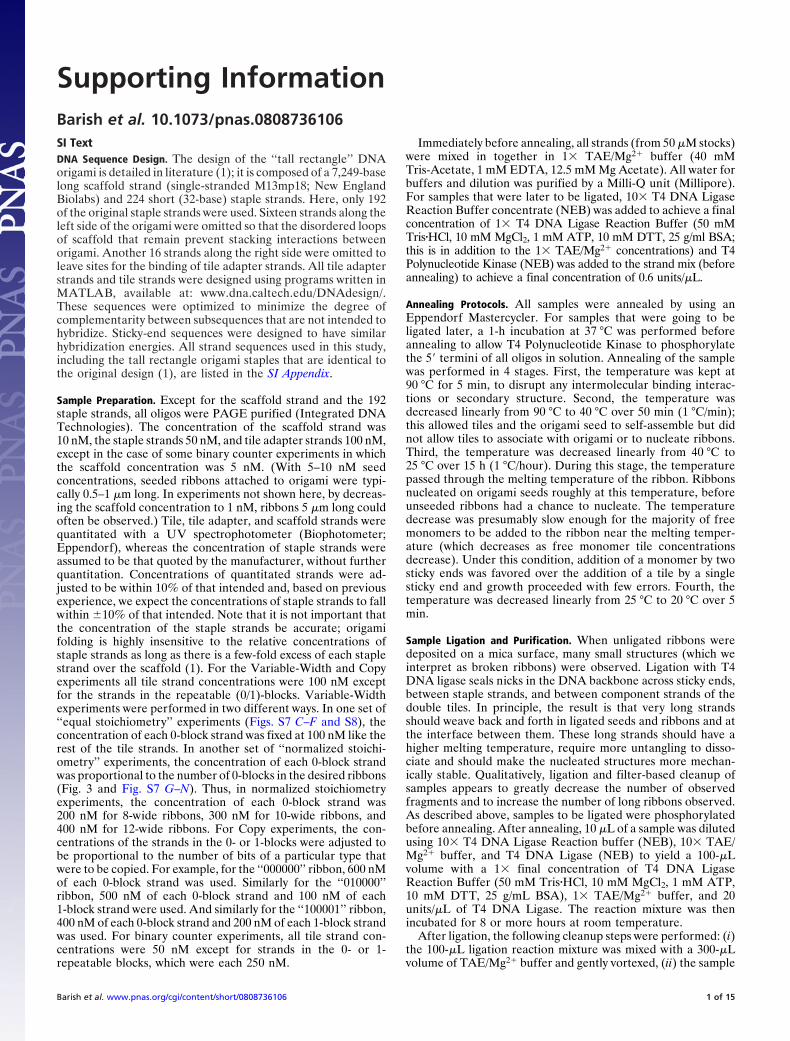
Fig. S2. Tile diagrams for the 0- and 1-blocks of the Copy tile set. The 0-block is also the repeatable block for the Variable-Width tile set. Arrows (� or �) indicatethe 5� ends of each strand. Tiles in the 1-block contain protruding internal hairpins to generate height contrast and allow for their identification under AFM.Blue and red dots indicate sticky ends specific to the 0- and 1-blocks, respectively. Green dots indicate sticky ends common to both 0- and 1-blocks that also occuron one edge of the nucleation barrier block and the Z78 double tile. Thus, either a 0- or 1-block can be adjacent to the nucleation barrier block and Z78 tile; further0- and 1-blocks can be juxtaposed next to each other in any order. Thus, a Copy ribbon starts on one edge with a Z78 double tile, continues through an arbitrarysequence of 0- and 1-blocks (possibly none), and then finishes with a nucleation block (and a Z56 double tile). Insets describe how information is processed byZIG/COUNT layer of the 0- and 1-blocks when they are used in the Binary counter. The left half of the Inset indicates information that is input via the top-leftand bottom-left sticky ends of the leftmost tile in a block (e.g., Z9 or ZB). The bottom left of the Inset indicates the value of the input digit, 0 or 1, from the previousZAG/COPY layer of the Binary Counter ribbon. The top left indicates the value of the carry bit that is being input (N � 0 or ‘‘no carry’’ and C � 1 or ‘‘carry’’). Thetop right of the Inset indicates the computed value of the digit in the current layer (in the current block), and the arrowhead indicates that the digit is outputto the next COPY layer. The output digit is the opposite of the input digit if the carry bit is set (C) and is otherwise unchanged. (This is the XOR of the two inputbits.) The bottom right indicates the computed value of the carry bit that is propagated along the current layer. The output carry bit is set (C) only if both theinput digit is 1 and the input carry bit is set (C). (This is the AND of the two input bits.)
Barish et al. www.pnas.org/cgi/content/short/0808736106 6 of 15

ATCGACCGTAGCTGGC
CTGCCTAAGACGGATT
CGAGACTGGCTCTGAC
TGAGCACCACTCGTGG
AAGGTCCG<TTCCAGGC
>CAGAAGTCCTGTCTTCAGGA
GCCAAGGCCGGTTCCG
GCTGATCGCGACTAGC
AGAAC
CTATC<
CTATC
>ATCTC
ZG
TTCGGATCAAGCCTAG
GGTCAGGTCCAGTCCA
GCGACCTCCGCTGGAG
AGAGCTGCTCTCGACG
TGGCAACGACCGTTGC
GACGTAGACTGCATCT
GACTCCTG>CTGAGGAC
CTCACAGAGTGT<
TTACC<
GATAG
>GATAG
TGTGT
ZE
AGATCGGTTCTAGCCA
CACAGTCCGTGTCAGG
ATGCTCCGTACGAGGC
GGTCAACCCCAGTTGG
CAAGGACCGTTCCTGG
CTGTGAGGGACACTCC
CAACTCCA>GTTGAGGT
TGTCTCACACAGAGTG<
AGTCT<
TTCCT
>GTTTG
ACTCA
ZH
CGGAGTCGTTGCCTCAGC
TTCGCTCGGCGCGAGCCGT
TT
T TTT
T
GTCGTGATCAGCACTA
TCCGCACCAGGCGTGG
AGCATCGCTCGTAGCG
GCTACGAGCGATGCTC
CTCGGAAC<GAGCCTTG
>CACTGTGCCGGTGACACGGC
CTGACAGAGACTGTCT
TGGTACTCACCATGAG
GTCAT
CAAAC<
CTATC
>TGAGT
ZF
CGGAGACGTTGCCTCTGC
TTGCCTTGGCCGGAACCG
TTT
T TTT
T(0)
(0)
(1)
(1)
(N)
(1)
(1)
(0)
(0)
CTCAGTGTGAGTCACA
TACACTCCATGTGAGG
ACAAGCGATGTTCGCT
GGTAGCGGCCATCGCC
CCGATTGGGGCTAACC
GAAGCAGGCTTCGTCC
CCGTGCCAGGCACGGT
TGCTTCACGAAG<
TCCAA<
GATAG
>CATAC
GACAG
Z8
TCTATCCTAGATAGGA
TGACGTGGACTGCACC
TGACCATAACTGGTAT
GCCTATTCCGGATAAG
CCGATGACGGCTACTG
>CATTCTGGGTAAGACC
CTACCGCAGATGGCGT
TGCCTAGCACGGATCG
CTGTC
ACCTT<>AGGTT
Z7
TTTT
GG-TCTTGCC-AGAAC
COPY layer COUNT layer
5*
6*
4
2
4
2
5*
6*
1*
1
7*
7
1
(C)
2*
(C)
(1) (C)
(0)
(C)
(0) (N)
(1)
7*
7
(C)1*
(C)1*
1(C)
1*
Z78-BC for Binary Counterexperiments
inert 2
ZIG layer logic forCarry Bit 0-Block
ZIG layer logic forCarry Bit 1-Block
+ Z11, Z10V to complete Carry Bit 0-Block
+ ZA, ZCV to complete Carry Bit-1 Block
Fig. S3. Tile diagrams for Binary Counter experiments. Arrows (� or �) indicate 5� ends of strands. To implement the Binary Counter, 4 new single tiles ZE, ZF,ZG, and ZH are added to the Copy tile set, and a new Z78-BC double tile is used. The ZG/ZE and ZF/ZH tile pairs are used in the context of two new types of blocks,a ‘‘Carry Bit 0-Block’’ and a ‘‘Carry Bit 1-Block’’ as diagrammed in the right-hand side of Fig. 2. Each new block uses two tiles from the original Copy tile set. ACarry Bit 0-Block includes ZG, ZE, Z11, and Z10V; a Carry Bit 1-Block includes ZF, ZH, ZA, and ZCV. Insets describe how information is processed by the ZIG/COUNTlayer of the Carry Bit 0- and 1-Blocks. The left half of the Inset indicates information that is input via the top-left and bottom-left sticky ends of the leftmost tilein a block (e.g., ZG or ZF). The bottom left of the Inset indicates the value of the input digit, 0 or 1, from the previous ZAG/COPY layer of the Binary Counter ribbon.The top left indicates the value of the carry bit that is being input (N � 0 or ‘‘no carry’’ and C � 1 or ‘‘carry). The top right of the Inset indicates the computedvalue of the digit in the current layer (in the current block), the arrowhead indicates that the digit is output to the next ZAG/COPY layer. The output digit is theopposite of the input digit if the carry bit is set (C) and is otherwise unchanged. (This is the XOR of the two input bits.) The bottom right indicates the computedvalue of the carry bit that is propagated along the current layer. The output carry bit is set (C) only if both the input digit is 1 and the input carry bit is set (C).(This is the AND of the two input bits.) The Z78-BC double tile inputs a carry bit of value ’’1‘‘ (C) to each new ZIG/COUNT layer to initiate the ripple carry addition.In an effort to lower the binary counter error rate, a ’’steric matching‘‘ scheme was implemented for the ’’C‘‘ sticky ends. The arms adjacent to input and output’’C‘‘ sticky ends were elongated and truncated, respectively, by 2 nucleotides so that an incorrectly added tile would suffer an additional energetic penalty forhaving the wrong shape. However, no obvious differences were discernible between experiments done with and without this particular error-reduction scheme.The fact that steric matching did not decrease the error rate suggests that ’’facet nucleation errors‘‘ (which occur when tiles bind facets via single bonds) maydominate the error rate (rather than growth errors that would incur a steric mismatch) because the current tile sets do not protect against facet nucleation errors(6, 7).
Barish et al. www.pnas.org/cgi/content/short/0808736106 7 of 15
Tile Adapters
16151413121110987654321
Adapter Set 16 Adaptor Set 15
Adapter Set 14 Adaptor Set 13
Adapter Set 12 Adapter Set 11
Adapter Set 9Adapter Set 10
Adapter Set 8
Adapter Set 6
Adapter Set 4
Adapter Set 2
Adapter Set 7
Adapter Set 5
Adapter Set 3
Adapter Set 1
tile adapter position
>
>
>
>
>
>
>
>
>
>
>
>
>
>
>
>GCAAGGACTGGCGTAC CCCCGTAT<
AGACGACCTTTTATCT CGGCCCAG<
AGTCTTCATCCATTAT GTCATGGG<
CTGGATACGTCTCTCA CCTGTACG<
TCCGCGCATGATAAAC TCAGTGTC<
AACTGCAATTTCATTT CCAGGAGG<
AAAACAGATGTCGCCC GGCACACA<
GCAGACTGAGGCCAAT TCCCACGG<
AACTGCCGATTATCTA GATGGTGA<
AGTAGAAGTTGTTTCA CCAACATG<
CGAAAAAGCTAAACAG CGTGTAAC<
CCTATTCGAGAATACC TGATCCTG<
GATAGACGTTGTTCGG CGAAGGCG<
AGACTGCGCGCTACAG TAGACCTG<
ATGAAAGTCCTCTTAA GGCGAACC<
TTTACATCGAGCGTCA AGGGGCTC<
GACCTATGCAGAGAGT GGACATGC NNNNN
AGGCGCGTACTATTTG AGTCACAG NNNNN
TTGACGTTAAAGTAAA GGTCCTCC NNNNN
TTTTGTCTACAGCGGG CCGTGTGT NNNNN
CGTCTGACTCCGGTTA
GCTTTTTCGATTTGTC GCACATTG NNNNN
GGATAAGCTCTTATGG ACTAGGAC NNNNN
CTATCTGCAACAAGCC GCTTCCGC NNNNN
TCTGACGC ATCTGGAC NNNNN
TACTTTCAGGAGAATT CCGCTTGG NNNNN
CGTTCCTGACCGCATG GGGGCATA NNNNN
TCTGCTGGAAAATAGA GCCGGGTC NNNNN
TCAGAAGTAGGTAATA CAGTACCC NNNNN
TTGACGGCTAATAGAT CTACCACT NNNNN
TCATCTTCAACAAAGT GGTTGTAC NNNNN
AAATGTAGCTCGCAGT TCCCCGAG NNNNN
AGGGTGCC NNNNN
GCGATGTC
ATTTTAGAAATTTCCC TCACTCGC
ACGAACCATTATGGCT GTGTCGAA
TGGATTATACTAACAA GGTGAGTC
ATCAAAATCACTTAAA ACGCGAGC
AATGCAGACAAGTCGA GGGGTGGG
TTTTGTTTTTTGCTAA GTGGAGTT
AGCGCCAACCAAATGG CATCGCAT
TGAGGCAGGTCCTCCA TGCGGGCT
AGATTAGAGTTGATTA CATCGAGA
GAGCAAAATTAATGGA CTACGAGG
AATTACTACCTTAGTA CGGAGCCC
TATAGAAGTTTAGTCT TGGGCAGC
AAAAGTAAAAAAATTC CACCTTAC
TGCCTTTATAGTTCAA CGGTTACG
CTGAAACAGATAATAA GAGTCGGG
GGAAATACTGCGAGTA TCGTGCAATAAAATCTTTAAAGGG AGTGAGCG NNNNN<
TGCTTGGTAATACCGA CACAGCTT NNNNN<
ACCTAATATGATTGTT CCACTCAG NNNNN<
TAGTTTTAGTGAATTT TGCGCTCG NNNNN<
TTACGTCTGTTCAGCT CCCCACCC NNNNN<
TCTAATCTCAACTAAT GTAGCTCT NNNNN<
CTCGTTTTAATTACCT GATGCTCC NNNNN<
TTAATGATGGAATCAT GCCTCGGG NNNNN<
ATATCTTCAAATCAGA ACCCGTCG NNNNN<
CCTTTATGACGCTCAT AGCACGTT NNNNN<
AAAACAAAAAACGATT CACCTCAA NNNNN<
TCGCGGTTGGTTTACC GTAGCGTA NNNNN<
ACTCCGTCCAGGAGGT ACGCCCGA NNNNN<
TTTTCATTTTTTTAAG GTGGAATG NNNNN<
ACGGAAATATCAAGTT GCCAATGC NNNNN<
GACTTTGTCTATTATT CTCAGCCC NNNNN<
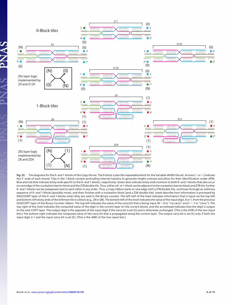
Fig. S4. Diagrams of all 16 tile adapters. Arrows (�) indicate the 5� ends of each strand. Tile adapters are abstracted as clear boxes with two internal rectangularstripes that can be color-coded to indicate the use of particular sticky ends. Here, no colors are used because all sticky-end sequences are undefined (indicatedby the ‘‘NNNNN’’ string in the tile sequence diagrams). As in Fig. 1, pink and green are used to represent tile adapter strands, whereas the black is used to representthe scaffold strand for the origami seed. Pink strands bind the scaffold; green strands bind pink strands and present sticky ends.
Barish et al. www.pnas.org/cgi/content/short/0808736106 8 of 15

Tile Adapter Patterns
Vari
able
-Wid
th R
ibb
on
s8-Wide 10-Wide 12-Wide
5-b
it B
inar
y C
ou
nte
r Rib
bo
ns
14-Wide C
op
y R
ibb
on
s
‘000000’ 16-Wide
‘010000’ 16-Wide
‘100001’ 16-Wide
‘011010’ 16-Wide
‘111111’ 16-Wide
16
15
13
14
12
11
10
9
8
7
5
6
4
3
2
1
tile adapter position
16
15
13
14
12
11
10
9
8
7
5
6
4
3
2
1
tile adapter position
Blunt Blunt Blunt
Not Used
Not Used
Not Used
Not Used
Not Used
Not Used
Not Used
Not Used
Not Used
Not Used
Not Used
Not Used
Not Used
Not Used
Not Used
Not Used
Not Used
Hairpin
Hairpin Hairpin Hairpin Hairpin Hairpin
11*
53*
21*
53*
21*
53*
21*
1
21*
53*
21*
53*
21*
53*
21*
1
53*
11*
21*
53*
21*
53*
21*
53*
21*
1
53*
21*
53*
11*
21* (N)
53*
21* (N)
53*
21* (N)
53*
21*
1
53*
21* (N)
53*
21* (N)
53*
11* (C)
21*
53*
21*
53*
21*
53*
21*
1
53*
21*
53*
21*
53*
21*
53*
11*
21*
53*
21*
53*
21*
53*
21*
1
53*
21*
53*
21*
53*
21*
53*
11*
21*
53*
21*
53*
21*
53*
21*
1
53*
21*
53*
21*
53*
21*
53*
11*
21*
53*
21*
53*
21*
53*
21*
1
53*
21*
53*
21*
53*
21*
53*
11*
21*
53*
21*
53*
21*
53*
21*
1
53*
21*
53*
21*
53*
21*
53*
11*
inert 1*
inert 1*
inert 1*
Blunt
Blunt
Blunt
Fig. S5. Tile adapter sticky-end patterns for all ribbon nucleation experiments. Tile adapters are abstracted as clear boxes with two internal rectangular stripesthat can be color-coded to indicate the use of particular sticky ends. Sticky-end arrangements for all Variable-Width, Copy, and Binary Counter experiments areexplicitly shown on columns of the 16 tile adapters. If a box is labeled ‘‘Not Used,’’ the strands for the tile adapter at that position were not added to the finalstrand mix, leaving a single-stranded loop of the scaffold strand at that site. Copy ribbon seeds ‘‘100001’’ and ‘‘011010’’ were also used for 6-bit Binary Counterexperiments shown in Fig. S11.
Barish et al. www.pnas.org/cgi/content/short/0808736106 9 of 15

10-Wide Variable-Width Ribbon ‘011010’ Copy Ribbon Binary Counter Ribbon
Anti-stacking & Ribbon Nucleation Schemes
=
=
==
Fig. S6. Anti-stacking and ribbon nucleation schemes. Multiple approaches were taken to inhibit �-stacking interactions between blunt ends of DNA helicesthat can lead to the aggregation of origami seed and ribbons. Thirty of 244 staple strands on the right and left edges of the original tall rectangle origami(described in ref. 1) were not used, so that, at sites where tile adapters are not present, loops of the scaffold strand (black) inhibit stacking interactions betweenseeds. Furthermore, in all experiments, the bottom Z56 double tile presented alternating blunt ends and hairpins to discourage stacking interactions betweenribbons. In Variable-Width experiments, the top double tile (Z78-VW) presented ‘‘inert’’ sticky ends with no binding partners at all sites along the top edge ofthe ribbon. In Copy and Binary Counter experiments, a top double tile was used that presented alternating inert sticky ends and hairpins. However, using thishairpin variant of the top double tile, we observed no clear differences in the number and type of stacking interactions between ribbons. Subjective experiencesuggests that ‘‘inert’’ sticky ends (those who sequence is not complementary to any tile sticky end) should be avoided because they can bind tiles anyway. Bluntends should be avoided because they can cause stacking between ribbons. Single-stranded loops and hairpins appear to be the best way to terminate helicesthat are intended to be ‘‘inert.’’ A further difference between the Variable-Width and Copy/Binary Counter experiments is that in the Variable-Widthexperiments, the top double tile (Z78-VW) attaches via two sticky ends to the tile adapters, whereas in the Copy/Binary Counter experiments, the top doubletile (Z78/Z78-BC) attaches to the tile adapters by only a single sticky end. In both cases, it is possible to nucleate via a series of exclusively favorable binding steps(with two sticky ends binding simultaneously), but in the Copy/Binary Counter nucleation scheme, the top double tile can bind via a favorable step only afterthe initial layer of zig-zag growth for the ribbon has completed.
Barish et al. www.pnas.org/cgi/content/short/0808736106 10 of 15

(d)
(e)
(f )
(b)
(o)
(p)
(h)
(i)
(j)
(l)
(m)
(n)
Unseeded VW-Ribbons/1X Repeatable Block (1 µm)
nW
nW+
n-42 X
+
+1X
4W +
+1X
nW
4WnW
+
+
n-42 X
kW
4W
+
(a) (c) (g) (k)
1X 1X1X 1X
26
2678
11
104
100
85
79
78
79
. . . +
. . . +
. . . +
. . . +
12148
14550
10390 145376
26404
2352441718
69200
28202
125876
8W Seeded VW-Ribbons/1X Repeatable Block (1 µm)
10W Seeded VW-Ribbons/1X Repeatable Block (1 µm)
12W Seeded VW-Ribbons/1X Repeatable Block (1 µm)
8W Seeded VW-Ribbons/2X Repeatable Block (1 µm)
10W Seeded VW-Ribbons/3X Repeatable Block (1 µm)
12W Seeded VW-Ribbons/4X Repeatable Block (1 µm)
n=8, Unseeded VW-Ribbons/2X Repeatable Block (1 µm)
n=10, Unseeded VW-Ribbons/3X Repeatable Block (1 µm)
n=12, Unseeded VW-Ribbons/4X Repeatable Block (1 µm)
Binary Counters (10 µm)
Binary Counters (5 µm)
Fig. S7. Examples of unligated Variable-Width ribbon images used for nucleation statistics and wide-field views of ligated Binary Counter ribbons. (a, c, g, andk) In schematic form, the Variable-Width experiment that was performed and the majority products of the reaction for comparison with images below showingexperimental data. nX indicates that n � 100 nM of each of a particular tile’s strands were used. In d–f and h–j, nW indicates that a particular origami seed encodeda ribbon n tiles wide, for n � 8, 10, and 12. For l–n, concentrations of tiles were made to match those of h–j, and n is given explicitly because there were no seeds.(d–f) Example data from the equal stoichiometry Variable-Width experiment reported in Fig. S8. (b) Example data from the unseeded control experiment forthe equal stoichiometry Variable-Width experiment. (h–n) Seeded (h–j) and unseeded (l–n) controls give example data for the normalized stoichiometryVariable-Width experiment reported in Fig. 3. In l–n, kW means that ribbons of a variety of widths k were produced, although the maximum k increased withn. No large lattices made from the 0-block tiles were observed in seeded samples h–j, but in the unseeded samples (l–n), with high concentrations (200–400 nM)of 0-block tiles, such lattices were relatively common; in l and n, we estimate that they contained �20% of tiles. In each sample image, the yellow number refersto the number of 1 � 1-�m AFM images that were examined to produce statistics, and the blue number refers to the total number of tiles counted to arrive ata given statistic. (o and p) Wide-field views of Binary Counter ribbons.
Barish et al. www.pnas.org/cgi/content/short/0808736106 11 of 15

0
0.1
0.2
0.3
0.4
0.5
0.6
0.7
0.8
0.9
1
Ribbon Width
Perc
ent o
f Tot
al T
iles
8W seeds 10W seeds 12W seeds
Exp
erim
enta
l Dat
aC
alcu
late
d T
ile D
istr
ibu
tio
ns
Ass
um
ing
Pe
rfec
t N
ucl
eati
on
Equal Stoichiometry Nucleation Statistics(1X Repeatable Block)
0
0.1
0.2
0.3
0.4
0.5
0.6
0.7
0.8
0.9
1
Ribbon Width
Perc
ent o
f Tot
al T
iles
No seeds 8W seeds 10W seeds 12W seeds
6W 8W 10W 12W 14W4W
6W 8W 10W 12W 14W4W
Fig. S8. Statistics for unseeded Variable-Width ribbons and Variable-Width ribbons nucleated by 8-, 10-, and 12-wide origami seeds using tiles at equalstoichiometry (100 nM). Here, each tile adapter strand was at 100 nM, each staple was at 50 nM, and the scaffold was at 10 nM; samples were unligated.‘‘Experimental Data’’ shows the experimentally observed tile distribution in ribbons with widths ranging from 4 to14 tiles. N � 12,147; 14,550; and 10,390 tiles,respectively, for the nucleated samples and N � 28,202 for the unnucleated sample. ‘‘Calculated Tile Distributions Assuming Perfect Nucleation’’ shows the tiledistribution that would theoretically occur if all ribbons were correctly nucleated and grew until free monomers for the 0-block were exhausted, subsequentlyallowing only 4-wide ribbons to grow using the remaining nucleation barrier tiles and double tiles. Discrepancies between experimental data and perfectnucleation estimates are partially caused by errors that decrease the width of nucleated ribbons as they nucleate or grow, such as lattice errors and prematurereversal errors (see Figs. S9 and S10). The high prevalence of spontaneously nucleated 4-wide ribbons (composed of ‘‘leftover’’ nucleation barrier and doubletiles) is the major difference between these equal stoichiometry experiments and the normalized stoichiometry experiments reported in Fig. 3; the results of thesetwo experiments were otherwise very similar.
Barish et al. www.pnas.org/cgi/content/short/0808736106 12 of 15

total copying errors
lattice errors
premature reversal errors
all apparently nucleated ribbons
ribbons attachedto origami
lattice error rate (%)
total copying error rate (%)
0 1 copying errors
1 0 copying errors
0 1 copying error rate (%)
1 0 copying error rate (%)
prem. rev. error rate (%)
total layers
.069 / .35 .061 / .31 .048 / .29.045 / .27 .12 / .40
11 8 6 2 3 7
51 42 29 17 14 252
1620zero positionsone positions 1611
.39 / 2.0 .42 / 2.1 .46 / 2.8 .47 / 2.8 .25 / .87 .53 / 3.1189 169 145 89 28 17
33 25 14 9 13 17
.53 / 3.1
total seeded ribbons 545
total nucleated correctly 303
48118 40725 31320 18846 11134 32319384 8007 5220 3141 3220 545
.21 / .54 .21 / .53 .19 / .56 .18 / .54 .25 / .44 15.6 / 46.5
.046 / .12 .039 / .10 .021 / .064 .038 / .12 .054 / .093 .43 / 1.3
62 50 35 19 17 259
.13 / .66 .12 / .62 .10 / .60.11 / .67 .15 / .53 8.0 / 47.5
correct nucleation rate (%) 55.6
ribbonsattached to origami,full width
ribbonsattachedto origami,correctnucleation
< 6-bit ribbonsfrom a
first layer statsfor structuresin b
total bits copied
a b c d e f
error ratesare expressed:
per bit / per layer
models show the types of ribbon considered in each column; emphasis shows which parts were counted.
Fig. S9. Statistics on unligated Copy ribbon error rates. Copy ribbons were nucleated from seeds encoding the bit pattern ‘‘011010’’ by using 300 nMconcentrations of each 0-block strand, 300 nM concentrations of each 1-block strand, 100 nM concentrations of each of the rest of the tile strands, and 10 nMconcentrations of the scaffold strand. A variety of error rates were collected on subpopulations of the observed structures; models show the range of structuresin each subpopulation. Column a includes all structures that were ‘‘apparently nucleated’’: all copy ribbons that were attached to origami as well as copy ribbonsthat started at least 4 bits wide (i.e., 12 tiles wide; based on our experience with other experiments, this assumes that the occurrence of spontaneously nucleated12-wide ribbons was very low). Column b includes all ribbons that were attached to origami, regardless of whether they nucleated with incorrect patterns ornucleated with less than full width. Column c includes ribbons that are both attached to origami and full width (i.e., they encoded 6 bits and were 16 tiles wide).Column d includes only ribbons that are simultaneously attached to origami, full width, and nucleated with the correct pattern. The populations of structuresin a–d are subsets of decreasing size: a�b�c�d. For a–d, counting of errors began after the first layer, i.e., errors at the origami–first layer interface were ignored;for a–e, parts of the ribbons that were not counted have been deemphasized. Counting of errors for structures in a and b was performed on the entire ribbon,whereas counting of errors for structures in c and d was performed only up to the point that any ribbon narrowed and became less than full width. Column egives statistics for less than full width, so it tallies the part of ribbons from a that had �6 bits (�16 tiles wide). Column f tallies errors in the first layer (arrows)of all ribbons attached to origami (the same structures as b). This allows a comparison of the error rates for nucleation and for copying in ribbons away fromthe nucleus; some rates change drastically; others do not. Errors are reported in both absolute numbers of observed errors and the rates (as a percentage) ofthe total number of observed bits and growth layers: layers are 1 tile thick, and each bit comprises 2 tiles. Per-bit rates and per-layer (or equivalently, per-seedfor f ) rates are separated by a ‘‘/’’. Copying errors (changes in the identity of a bit) are separated into 13 0 and 03 1 errors to highlight the great asymmetryin these error rates, which is presumably due to an energetic cost for association incurred by the hairpins on the 1-block tiles. Both rates decrease by approximatelya factor of 10 (per layer or per bit) when considering growth away from the first layer. (Note that the total copying error rate is not simply an average of thetwo kinds of copying error rates, because the denominator changes from the number of 0 or 1 bits to the total number of bits.) Two kinds of errors cause ribbonsto narrow and represent fewer bits. One, a ‘‘lattice error,’’ occurs when there is a geometric defect in the lattice as shown in Fig. S10. The second, a ‘‘prematurereversal error,’’ occurs when a double tile binds where a tile from a 0- or 1-block should go, and this causes a premature reversal of growth direction thatterminates the row. Premature reversal errors are the most common type of error (including copy errors) by a factor of at least 3 when considering growth awayfrom the nucleus (in the first layer, lattice and premature reversal errors happen at nominally equal rates). For example, when comparing b with f, 40% of latticedefects occurred in the first layer of growth, whereas only 9% of premature reversal errors occurred in the first layer. Lattice errors decrease drastically in rateaway from the first layer (by a factor of 10 per layer), whereas the rate of premature reversal errors decreases by only 1/3.
Barish et al. www.pnas.org/cgi/content/short/0808736106 13 of 15
*
*
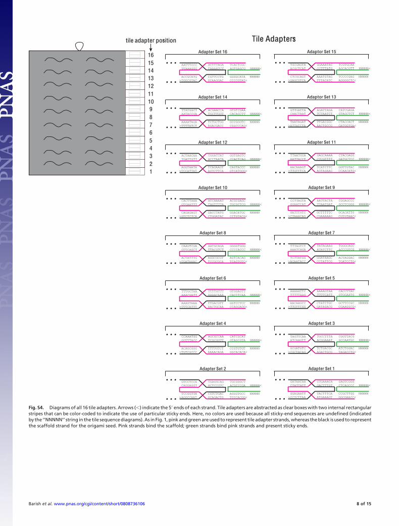
Fig. S10. Example of a lattice defect during nucleation in a ‘‘000000’’ Copy ribbon. (Scale bars, 20 nm.) Yellow dots indicate the center positions of the 16 tileadapters on an origami seed specifying a 16-wide ribbon, whereas red dots indicate the center positions of tiles in the 14-wide ribbon that is nucleated. A solidwhite line marks the edge of the origami seed at the base of the tile adapters: Dashed white lines bound the third layer of tiles in the ribbon. The lattice defectis indicated by an asterisk. Connections between red dots (Right) show how sticky-end pairing interactions coordinate around the lattice defect to cause theribbon to shrink by 2 tiles (the size of a 0- or 1-block) from its programmed width of 16 tiles. Tile arms are evidently flexible enough to accommodate this kindof error. Similar lattice defects during nucleation have been observed for all types of ribbon used in this work. The mechanism responsible for the lattice defectis unknown, but we hypothesize that it is due to the mismatch in the interhelix spacing of the origami and the lattice constant for the DNA tile ribbon. Even thoughboth structures encompass 32 DNA helices, they have different patterns and frequencies of crossovers, which change the forces that balance the electrostaticrepulsion between helices. This appears to affect their relative size in the direction perpendicular to the helix axes, as marked by the solid and white dashed linesfor the origami and ribbon, respectively. The interhelix spacing in the 32-helix origami used here (with 1.5 turns between adjacent crossovers) is �1 nm, whichgives a length (along the white solid line) for the origami of �95 nm. The lattice spacing for tile lattices has been measured at �6–7 nm per tile, which wouldgive a width of 96–112 nm for a 16-wide ribbon along the white dashed line). There is a noticeable ‘‘flare’’ at the junction between many origami and the ribbonsthat they nucleate, indicating that a relaxed 16-tile-wide ribbon is indeed wider that an origami is tall. For example, see Fig. 4, which shows noticeable curvatureat the origami-ribbon junction for the ‘‘000000’’ ribbon. When measured from Fig. 4, the ratio of sizes is �1.12, which means that if the origami is 95 nm, thenthe ribbon is �106 nm (absolute AFM measurements are probably no better than 5%). A fix for this problem might be to use an origami with 1.5-nm interhelixspacing (as appears to be true for origami with 2.5-turn spacing between adjacent crossovers): This approach should yield an �110.5-nm-tall, 32-helix origamiseed. We note that width-shrinking is also observed to occur later on in growth, due both to lattice defects like that shown here and a much more prevalenttype of error that we term a ‘‘premature reversal error.’’ Statistics on lattice defects and premature reversal errors, both during nucleation and for later growth,are given in Fig. S9.
Barish et al. www.pnas.org/cgi/content/short/0808736106 14 of 15

Other Supporting Information Files
SI Appendix (PDF)
010110 = 22
332434
3536
3742
43
45 46
44
47 48
49
a
343335
3637
4243
44...45...100001 = 33
b
Fig. S11. Binary Counter crystals nucleated with alternative initial values. (a) Using a seed with the ‘‘100001’’-bit string to create a binary counting pattern thatstarts at 33, using tiles without the shape modifications for the carry bit. The seed is identical to the one used for the Copy tile set with the same bit string. Theyellow outline delineates nucleation phase growth, i.e., the initial series of tiles that can be favorably attached by their left sticky ends, prior to zig-zag growth.A single error occurred during zig-zag growth, shown in yellow. In this experiment, it appears that we used a faulty preparation of the lower (magenta)double-tile molecules; it seems unlikely that proper zig-zag growth was occurring. Therefore, we presume that the ZAG/COPY layer growth was not initiatedby the lower double tile but, rather, occurred by unfavorable attachment of tiles and facet nucleation. Thankfully, facet nucleation on the ZAG/COPY layer doesnot cause bit copying errors. Because the overall error rate is low, we presume that in this crystal the ZIG/COUNT layer initiated properly from the upper doubletile; facet nucleation of the ZIG/COUNT layer would be likely to result in a counting error. (b) Using a seed with the ‘‘010110’’ bit string to create a binary countingpattern that starts at 22, using tiles with shape modifications to encode the carry bit. The seed is identical to the one used for the Copy tile set with the samebit string. (Note that here, the string is read from bottom to top, whereas there, it was read from top to bottom and written ‘‘011010.’’) There was 1 growtherror during nucleation and 2 growth errors during zig-zag growth. The growth error rates for these two crystals are compatible with what we have observedin the ‘‘00001’’-nucleated Binary Counter crystals, and the nucleation errors are compatible with the measurements for Copy crystals.
Barish et al. www.pnas.org/cgi/content/short/0808736106 15 of 15

![Achieving Room Temperature DNA Amplification by …[Supporting Information to Accompany Manuscript] Achieving Room Temperature DNA Amplification by Dialling in Destabilization B. Safeenaz](https://img.dokumen.tips/doc/110x75/5ece72122f3ed614a043cc15/achieving-room-temperature-dna-amplification-by-supporting-information-to-accompany.jpg)