Embed Size (px)
Citation preview

Technify Motors GmbHPlatanenstraße 14
D - 09356 St. Egidien
Tel. +49 37204 696-0Fax +49 37204 [email protected]
Installation ManualCD-135 / CD-155
Doc. No.: IM-02-02Version: 4/2
CAUTION:This installation manual must be read completely
before installing the engine, as it contains importantinformation concerning safety for assembly,
safety and operation.
Note:The Installation Manual
must be included at the time of sale of the engine / aircraft.
Note:Please report any service difficulties to the Technical
Support Center at Technify Motors GmbH.See above for contact information.
Installation Manual - Issue 4 / Revision 2
P/N: 05-7200-H210016

This page intentionally left blank

Installation ManualCD-135 / CD-155
IM-02-02
Table of contents
Table of contents ......................................................1List of Figures ...........................................................1
0.1 List of Revisions ........................................................30.2 List of applicable chapters.........................................70.3 Preliminary Remarks.................................................8
1 Introduction ............................................................11.1 General Information .................................................11.2 Abbreviations ...........................................................11.3 Engine Identification .................................................21.4 Copyright © ..............................................................21.5 Engine Variants and approved Installations .............2
2 Safety ......................................................................12.1 Safety Recommendations ........................................12.2 Safety Information ....................................................22.3 Legal Notice .............................................................42.4 Accompanying applicable Documents .....................4
3 Engine Description ................................................13.1 Engine Designation ..................................................13.2 Engine Description ...................................................13.3 Scope of Supply .......................................................13.4 Engine Views ...........................................................2
4 Technical Data ........................................................14.1 General Information .................................................14.2 Dimensions and Weights .........................................14.3 Engine and Gearbox Data ........................................2
4.3.1 Specifications ..............................................24.3.2 Engine Limitations .......................................2
4.4 Fuel / Oil / Coolant ...................................................54.5 Power Curve ............................................................94.6 Low Temperature Data and Climate Classes of Diesel
in Europe ................................................................11
Rev. No.:Rev. Date:
Chapter:Issue:Issue Date:Page:Content:
02-IM-01-02430.07.201416
230.01.2015
Installation ManualCD-135 / CD-155
IM-02-02
5 Transport and Packaging ......................................15.1 Packaging ................................................................15.2 Transport ..................................................................15.3 Protective Covers .....................................................35.4 Preservation of the Engine .......................................3
6 Engine Mounting and Installation Position .........16.1 General ....................................................................16.2 Center of Gravity of the Engine ................................16.3 Location of the Engine Mounts .................................26.4 Permissible Loads at the Engine Mounts .................36.5 Permissible Installation Positions .............................36.6 General Information on Engine Mounting ................4
7 Exhaust System .....................................................17.1 General ....................................................................17.2 Design of the Exhaust System .................................17.3 Requirements for the Exhaust System .....................37.4 General Information on the Exhaust System ...........3
8 Cooling System ......................................................18.1 General ....................................................................18.2 Requirements for the Cooling System .....................38.3 Dimension and Location of Connections ..................58.4 Coolant ...................................................................108.5 General Information about the Coolant System .....118.6 Display Instrument:
Requirements and Connections .............................118.7 Inspection of the Coolant System ..........................12
9 Cooling Air Duct System .......................................19.1 General ....................................................................19.2 Requirements for the Cooling Air Duct System ........1
Chapter:Issue:Issue Date:Page:Content:
02-IM-01-02430.07.201426
Rev. No.:Rev. Date:
230.01.2015
Installation ManualCD-135 / CD-155
IM-02-02
10 Lubricating System ................................................110.1 General ....................................................................110.2 Requirements for the Lubricating System
(CD-135 only) ...........................................................110.3 Integrated Oil Separator
(CD-135 only) ...........................................................310.4 Connections: Dimensions, Location and Length of
Hoses .......................................................................410.4.1 Breather crankcase .....................................410.4.2 Oil Cooler (CD-135 only) .............................6
10.5 Display Instruments:Requirements and Connections ...............................710.5.1 Requirements for the display instrument .....710.5.2 Oil pressure sensor and appropriate display
instrument ....................................................8
11 Fuel System ............................................................111.1 General ....................................................................111.2 Requirements for the Fuel System ...........................2
11.2.1 General information .....................................211.2.2 Lines ............................................................311.2.3 Drain module ...............................................311.2.4 Fuel filter module .........................................411.2.5 Combined drain and fuel filter module
(Technify Motors GmbH) .............................411.3 Connecting Points and Dimensions .........................5
11.3.1 Fuel intake ...................................................511.3.2 Fuel return ...................................................6
11.4 Display Instrument:Requirements and Connections ...............................7
Rev. No.:Rev. Date:
Chapter:Issue:Issue Date:Page:Content:
02-IM-01-02430.07.201436
230.01.2015
Installation ManualCD-135 / CD-155
IM-02-02
12 Intake System .........................................................112.1 General ....................................................................112.2 Intake System Requirements ...................................1
12.2.1 Air filter ........................................................112.2.2 Intercooler ...................................................1
12.3 Connections: Dimensions and Locations .................212.3.1 Air Filter to Turbocharger Compressor
Housing .......................................................212.3.2 Hoses ..........................................................212.3.3 Turbocharger Compressor Housing to
Intercooler ...................................................3
13 Electrical System and FADEC Installation ...........113.1 General ....................................................................113.2 FADEC Installation General .....................................213.3 FADEC Electrical Power Supply ..............................313.4 Installation FADEC Pressure Sensor Lines .............413.5 Layout of the Electrical System ................................513.6 Wiring .......................................................................513.7 Connecting Points Wiring harness / FADEC / Battery
Relay ........................................................................713.8 Technical Data of the Electrical Components and their
Connections .............................................................713.8.1 Internal alternator ........................................713.8.2 Wiring of the alternator ................................713.8.3 Voltage warning ...........................................913.8.4 Electrical starter ...........................................913.8.5 Starter relay .................................................913.8.6 Starter switch .............................................1013.8.7 Glow relay and glow plug control unit
(GPC) ........................................................1013.8.8 Glow display ..............................................1013.8.9 Battery relay ..............................................1013.8.10 Battery .......................................................1113.8.11 Engine Master ...........................................1213.8.12 Main switch / Main Bus switch ...................1213.8.13 Additional ground power connection .........1213.8.14 CAN connector ..........................................1213.8.15 FADEC warning lights ...............................12
Chapter:Issue:Issue Date:Page:Content:
02-IM-01-02430.07.201446
Rev. No.:Rev. Date:
230.01.2015
Installation ManualCD-135 / CD-155
IM-02-02
13.8.16 Start phase monitoring ..............................1313.9 Instrument connections ..........................................15
13.9.1 CED-125 engine display instrument ..........1513.10 Electromagnetic Compatibility and Environmental
Testing Categories for the FADEC and Wiring Harness ..................................................................1713.10.1 FADEC D48 (P/N: 05-7611-K0001xx) .......1713.10.2 FADEC D4 (P/N: 05-7611-E0019xx) .........18
13.11 Lightning Protection ...............................................1913.12 Check List for Acceptance Inspection of the
Installation ..............................................................20
14 Propeller Drive ........................................................114.1 General ....................................................................114.2 Technical Data for the Propeller Flange ...................114.3 Propeller ...................................................................2
14.3.1 Installation Information ................................214.3.2 Propeller Limitations ....................................214.3.3 Propeller control ..........................................514.3.4 Basic testing requirements ..........................614.3.5 Flight, operation verification ........................6
14.4 Constant Speed Unit ..............................................10
15 Vacuum Pump ........................................................115.1 General ....................................................................115.2 Technical Data for the Vacuum Pump .....................115.3 Connection and Connection Locations ....................2
Rev. No.:Rev. Date:
Chapter:Issue:Issue Date:Page:Content:
02-IM-01-02430.07.201456
230.01.2015
Installation ManualCD-135 / CD-155
IM-02-02
This page intentionally left blank
Chapter:Issue:Issue Date:Page:Content:
02-IM-01-02430.07.201466
Rev. No.:Rev. Date:
230.01.2015

Installation ManualCD-135 / CD-155
IM-02-02
List of Figures
Fig. 0.1 Explanation of the chapter numbering systemFig. 1.1 Engine identificationFig. 3.1 Front view of CD-135 (dimensions in mm)Fig. 3.2 Top view of CD-135 (dimensions in mm)Fig. 3.3 Side view (left) of CD-135 (dimensions in mm)Fig. 3.4 Side view (right) of CD-135 (dimensions in mm)Fig. 3.5 Front view of CD-155 (dimensions as above)Fig. 3.6 Top view of CD-155 (dimensions as above)Fig. 3.7 Side view (left) of CD-155 (dimensions as above)Fig. 3.8 Side view (right) of CD-155 (dimensions as above)Fig. 4.1 BankingFig. 4.2 Power curve of CD-135 (TAE 125-02-99)Fig. 4.3 Power curve of CD-155 (TAE 125-02-114)Fig. 5.1 Lifting eyelet at gearboxFig. 5.2 Lifting eyelet at cylinder head coverFig. 5.3 Lifting eyelet at cylinder headFig. 7.1 Example of a possible installation of the exhaust
pipeFig. 8.1 Interface cooling circuit CD-135Fig. 8.2 Interface cooling circuit CD-155Fig. 8.3 Bleed line connectionFig. 8.4 Coolant hose connection CD-135 Radiator Inlet)Fig. 8.5 Coolant hose connection CD-155 (Radiator Inlet)Fig. 8.6 Coolant hose connection CD-135 (Radiator Outlet)Fig. 8.7 Coolant hose connection CD-155 (Radiator Outlet)Fig. 8.8 Coolant supply line from the expansion tankFig. 8.9 Heating lines CD-135Fig. 8.10 Heating supply line CD-155Fig. 9.1 Air inlet temperature diagramFig. 10.1 Oil System Schematic with BlowbyFig. 10.2 Oil System Schematic with Integrated Oil SeparatorFig. 10.3 Integrated Oil SeparatorFig. 10.4 Breather crankcase CD-135 and CD-155Fig. 10.5 Oil Cooler connectionsFig. 11.1 Fuel intakeFig. 11.2 Return pipeFig. 12.1 Air hose connection at the turbochargerFig. 12.2 Adapter to K16 turbocharger
Rev. No.:Rev. Date:
Chapter:Issue:Issue Date:Page:Content:
02-IM-01-02430.07.201412
230.01.2015

Installation ManualCD-135 / CD-155
IM-02-02
Fig. 12.3 Flange intercooler to V22 turbochargerFig. 12.4 Connection intercooler to V22 turbocharger
CD-135Fig. 12.5 Connection intercooler to V22 turbocharger
CD-155Fig. 12.6 Connection intercooler to intake manifoldFig. 13.1 Preferred FADEC installationFig. 13.2 installation principles: power diodeFig. 13.3 installation principles: starter relay (recommended)Fig. 14.1 Propeller shaft flange [mm]Fig. 14.2 Propspeed target diagramFig. 14.3 Definition overshoot behaviorFig. 14.4 Connecting the pressure gauge / setting the
constant speed unitFig. 15.1 Volume flow diagramFig. 15.2 Vacuum pump connections
Chapter:Issue:Issue Date:Page:Content:
02-IM-01-02430.07.201422
Rev. No.:Rev. Date:
230.01.2015

Installation ManualCD-135 / CD-155
IM-02-02
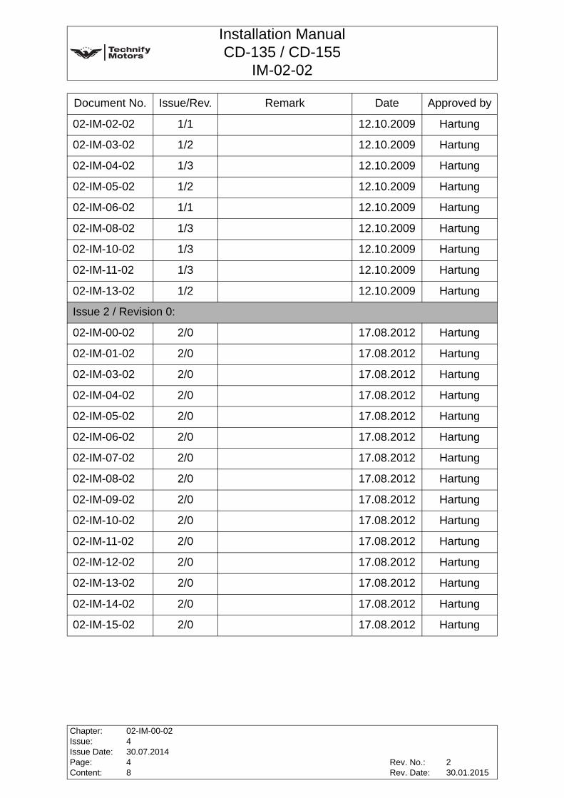
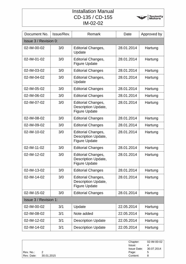
0.1 List of Revisions
Document No. Issue/Rev. Remark Date Approved by
Issue 1 / Revision 1:
02-IM-00-02 1/1 15.11.2006 Hartung
02-IM-08-02 1/1 15.11.2006 Hartung
02-IM-10-02 1/1 15.11.2006 Hartung
02-IM-11-02 1/1 15.11.2006 Hartung
02-IM-12-02 1/1 15.11.2006 Hartung
Issue 1 / Revision 2:
02-IM-00-02 1/2 27.02.2007 Hartung
02-IM-03-02 1/1 27.02.2007 Hartung
02-IM-04-02 1/1 27.02.2007 Hartung
02-IM-00-02 1/2 27.02.2007 Hartung
02-IM-03-02 1/1 27.02.2007 Hartung
02-IM-04-02 1/1 27.02.2007 Hartung
Issue 1 / Revision 3:
02-IM-00-02 1/3 29.06.2007 Hartung
02-IM-04-02 1/2 29.06.2007 Hartung
02-IM-05-02 1/1 29.06.2007 Hartung
02-IM-08-02 1/2 29.06.2007 Hartung
02-IM-10-02 1/2 29.06.2007 Hartung
02-IM-11-02 1/2 29.06.2007 Hartung
02-IM-12-02 1/2 29.06.2007 Hartung
02-IM-13-02 1/1 29.06.2007 Hartung
02-IM-14-02 1/1 29.06.2007 Hartung
02-IM-15-02 1/1 29.06.2007 Hartung
Issue 1 / Revision 4:
02-IM-00-02 1/4 12.10.2009 Hartung
02-IM-01-02 1/1 12.10.2009 Hartung
Rev. No.:Rev. Date:
Chapter:Issue:Issue Date:Page:Content:
02-IM-00-02430.07.201438
230.01.2015
Installation ManualCD-135 / CD-155
IM-02-02
02-IM-02-02 1/1 12.10.2009 Hartung
02-IM-03-02 1/2 12.10.2009 Hartung
02-IM-04-02 1/3 12.10.2009 Hartung
02-IM-05-02 1/2 12.10.2009 Hartung
02-IM-06-02 1/1 12.10.2009 Hartung
02-IM-08-02 1/3 12.10.2009 Hartung
02-IM-10-02 1/3 12.10.2009 Hartung
02-IM-11-02 1/3 12.10.2009 Hartung
02-IM-13-02 1/2 12.10.2009 Hartung
Issue 2 / Revision 0:
02-IM-00-02 2/0 17.08.2012 Hartung
02-IM-01-02 2/0 17.08.2012 Hartung
02-IM-03-02 2/0 17.08.2012 Hartung
02-IM-04-02 2/0 17.08.2012 Hartung
02-IM-05-02 2/0 17.08.2012 Hartung
02-IM-06-02 2/0 17.08.2012 Hartung
02-IM-07-02 2/0 17.08.2012 Hartung
02-IM-08-02 2/0 17.08.2012 Hartung
02-IM-09-02 2/0 17.08.2012 Hartung
02-IM-10-02 2/0 17.08.2012 Hartung
02-IM-11-02 2/0 17.08.2012 Hartung
02-IM-12-02 2/0 17.08.2012 Hartung
02-IM-13-02 2/0 17.08.2012 Hartung
02-IM-14-02 2/0 17.08.2012 Hartung
02-IM-15-02 2/0 17.08.2012 Hartung
Document No. Issue/Rev. Remark Date Approved by
Chapter:Issue:Issue Date:Page:Content:
02-IM-00-02430.07.201448
Rev. No.:Rev. Date:
230.01.2015
Installation ManualCD-135 / CD-155
IM-02-02
Issue 3 / Revision 0:
02-IM-00-02 3/0 Editorial Changes,Update
28.01.2014 Hartung
02-IM-01-02 3/0 Editorial Changes,Figure Update
28.01.2014 Hartung
02-IM-03-02 3/0 Editorial Changes 28.01.2014 Hartung
02-IM-04-02 3/0 Editorial Changes,Update
28.01.2014 Hartung
02-IM-05-02 3/0 Editorial Changes 28.01.2014 Hartung
02-IM-06-02 3/0 Editorial Changes 28.01.2014 Hartung
02-IM-07-02 3/0 Editorial Changes,Description Update, Figure Update
28.01.2014 Hartung
02-IM-08-02 3/0 Editorial Changes 28.01.2014 Hartung
02-IM-09-02 3/0 Editorial Changes 28.01.2014 Hartung
02-IM-10-02 3/0 Editorial Changes,Description Update, Figure Update
28.01.2014 Hartung
02-IM-11-02 3/0 Editorial Changes 28.01.2014 Hartung
02-IM-12-02 3/0 Editorial Changes,Description Update, Figure Update
28.01.2014 Hartung
02-IM-13-02 3/0 Editorial Changes 28.01.2014 Hartung
02-IM-14-02 3/0 Editorial Changes,Description Update, Figure Update
28.01.2014 Hartung
02-IM-15-02 3/0 Editorial Changes 28.01.2014 Hartung
Issue 3 / Revision 1:
02-IM-00-02 3/1 Update 22.05.2014 Hartung
02-IM-08-02 3/1 Note added 22.05.2014 Hartung
02-IM-12-02 3/1 Description Update 22.05.2014 Hartung
02-IM-14-02 3/1 Description Update 22.05.2014 Hartung
Document No. Issue/Rev. Remark Date Approved by
Rev. No.:Rev. Date:
Chapter:Issue:Issue Date:Page:Content:
02-IM-00-02430.07.201458
230.01.2015

Installation ManualCD-135 / CD-155
IM-02-02
Issue 4 / Revision 0:
all 4/0 Engine Name changed from Centurion in Continental Diesel, C 2.0 to CD-135 and C 2.0S to CD-155 Figure Update
30.07.2014 Hartung
Issue 4 / Revision 1:
02-IM-00-02 4/1 Update 28.11.2014 Hartung
02-IM-04-02 4/1 Fuel additive added 28.11.2014 Hartung
02-IM-05-02 4/1 Note update 28.11.2014 Hartung
02-IM-08-02 4/1 Figure deleted 28.11.2014 Hartung
02-IM-13-02 4/1 FADEC D48 / D4 Update, Start phase monitoring added
28.11.2014 Hartung
02-IM-14-02 4/1 Propeller requirements added
28.11.2014 Hartung
Issue 4 / Revision 2
02-IM-14-02 4/2 Update max. propeller weight Update csu pressure
30.01.2015 Hartung
Document No. Issue/Rev. Remark Date Approved by
Chapter:Issue:Issue Date:Page:Content:
02-IM-00-02430.07.201468
Rev. No.:Rev. Date:
230.01.2015
Installation ManualCD-135 / CD-155
IM-02-02
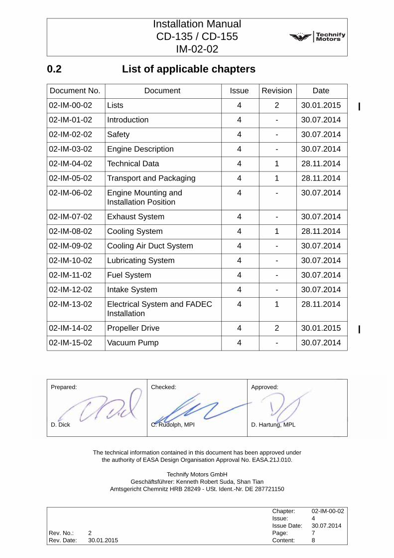
0.2 List of applicable chapters
signatures
Document No. Document Issue Revision Date
02-IM-00-02 Lists 4 2 30.01.2015
02-IM-01-02 Introduction 4 - 30.07.2014
02-IM-02-02 Safety 4 - 30.07.2014
02-IM-03-02 Engine Description 4 - 30.07.2014
02-IM-04-02 Technical Data 4 1 28.11.2014
02-IM-05-02 Transport and Packaging 4 1 28.11.2014
02-IM-06-02 Engine Mounting and Installation Position
4 - 30.07.2014
02-IM-07-02 Exhaust System 4 - 30.07.2014
02-IM-08-02 Cooling System 4 1 28.11.2014
02-IM-09-02 Cooling Air Duct System 4 - 30.07.2014
02-IM-10-02 Lubricating System 4 - 30.07.2014
02-IM-11-02 Fuel System 4 - 30.07.2014
02-IM-12-02 Intake System 4 - 30.07.2014
02-IM-13-02 Electrical System and FADEC Installation
4 1 28.11.2014
02-IM-14-02 Propeller Drive 4 2 30.01.2015
02-IM-15-02 Vacuum Pump 4 - 30.07.2014
Prepared: Checked: Approved:
D. Dick C. Rudolph, MPI D. Hartung, MPL
The technical information contained in this document has been approved under the authority of EASA Design Organisation Approval No. EASA.21J.010.
Technify Motors GmbHGeschäftsführer: Kenneth Robert Suda, Shan Tian
Amtsgericht Chemnitz HRB 28249 - USt. Ident.-Nr. DE 287721150
Rev. No.:Rev. Date:
Chapter:Issue:Issue Date:Page:Content:
02-IM-00-02430.07.201478
230.01.2015
Installation ManualCD-135 / CD-155
IM-02-02
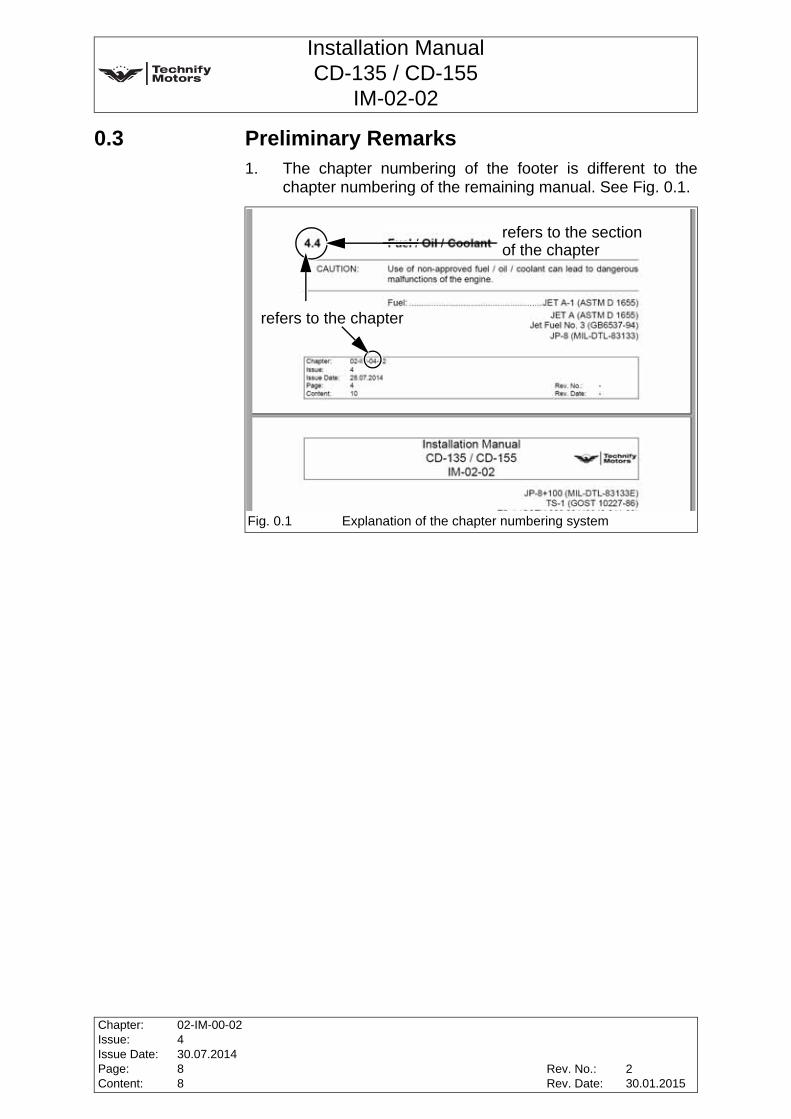
0.3 Preliminary Remarks1. The chapter numbering of the footer is different to the
chapter numbering of the remaining manual. See Fig. 0.1.
Fig. 0.1 Explanation of the chapter numbering system
refers to the chapter
refers to the sectionof the chapter
Chapter:Issue:Issue Date:Page:Content:
02-IM-00-02430.07.201488
Rev. No.:Rev. Date:
230.01.2015
Installation ManualCD-135 / CD-155
IM-02-02
1 Introduction
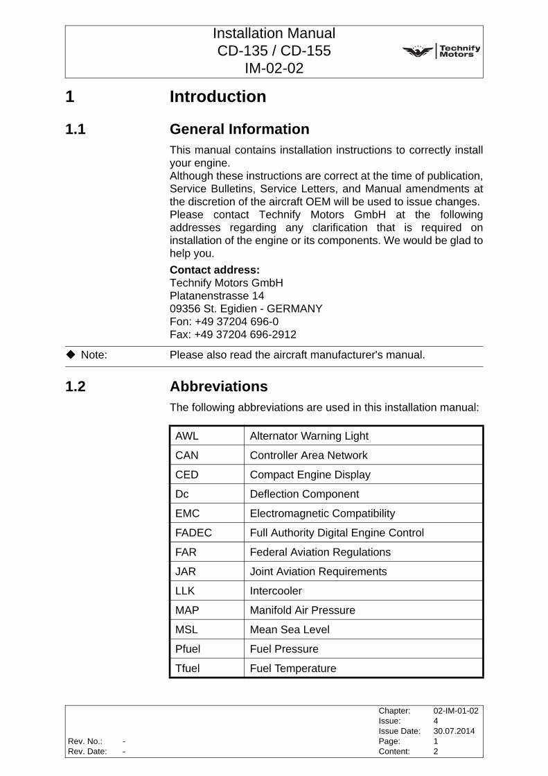
1.1 General InformationThis manual contains installation instructions to correctly installyour engine.Although these instructions are correct at the time of publication,Service Bulletins, Service Letters, and Manual amendments atthe discretion of the aircraft OEM will be used to issue changes. Please contact Technify Motors GmbH at the followingaddresses regarding any clarification that is required oninstallation of the engine or its components. We would be glad tohelp you.Contact address:Technify Motors GmbHPlatanenstrasse 1409356 St. Egidien - GERMANYFon: +49 37204 696-0Fax: +49 37204 696-2912
1.2 AbbreviationsThe following abbreviations are used in this installation manual:
Note: Please also read the aircraft manufacturer's manual.
AWL Alternator Warning Light
CAN Controller Area Network
CED Compact Engine Display
Dc Deflection Component
EMC Electromagnetic Compatibility
FADEC Full Authority Digital Engine Control
FAR Federal Aviation Regulations
JAR Joint Aviation Requirements
LLK Intercooler
MAP Manifold Air Pressure
MSL Mean Sea Level
Pfuel Fuel Pressure
Tfuel Fuel Temperature
Rev. No.:Rev. Date:
Chapter:Issue:Issue Date:Page:Content:
02-IM-01-02430.07.201412
--

Installation ManualCD-135 / CD-155
IM-02-02
1.3 Engine Identification
1.4 Copyright ©
1.5 Engine Variants and approved InstallationsThe engine variants and approved installations are listed inService Bulletin TM TAE 000-0007.
Fig. 1.1 Engine identification
Data plate
Note: The serial number of the engine must be quoted in the event ofany inquiries.
Note: Further information about the key for serial numbers of theengine is published in Service Bulletin TM TAE 000-0005.
This manual, the technical data and the information contained therein are the property of Technify Motors GmbH and may not
be reproduced either in full or in part or passed on to a third party without written consent
from Technify Motors GmbH. This text must be included in any full or partial reproduction of
this documentation.
Copyright © Technify Motors GmbH
CAUTION: The engine must be installed with an approved softwaremapping according to Service Bulletin TM TAE 000-0007.
Chapter:Issue:Issue Date:Page:Content:
02-IM-01-02430.07.201422
Rev. No.:Rev. Date:
--

Installation ManualCD-135 / CD-155
IM-02-02
2 SafetyThe relevant provisions of the employer's liability insuranceorganization and the other relevant safety rules of e.g. the tradesupervision authority must be observed. The work described below shall only be performed by trainedpersons or specialized companies who hold current and validlicenses from the aviation authority to carry out such work.
2.1 Safety RecommendationsThe following symbols and warning signs are used in the manual.They must be heeded strictly to prevent personal injury andmaterial damage, to avoid impairment of the operational safety ofthe aircraft and to rule out any damage to the aircraft as aconsequence of improper handling.
WARNING: Disregarding these safety rules can cause personal injury oreven death.
CAUTION: Disregarding these special instructions and safety measurescan cause damage to the engine or other components.
Note: Additional note or instructions for better understanding of aninstruction.
Rev. No.:Rev. Date:
Chapter:Issue:Issue Date:Page:Content:
02-IM-02-02430.07.201414
--
Installation ManualCD-135 / CD-155
IM-02-02
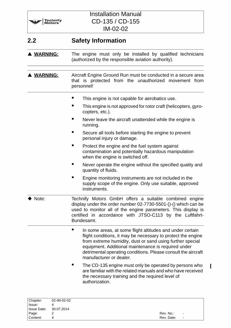
2.2 Safety Information
• This engine is not capable for aerobatics use.
• This engine is not approved for rotor craft (helicopters, gyro- copters, etc.).
• Never leave the aircraft unattended while the engine is running.
• Secure all tools before starting the engine to prevent personal injury or damage.
• Protect the engine and the fuel system against contamination and potentially hazardous manipulation when the engine is switched off.
• Never operate the engine without the specified quality and quantity of fluids.
• Engine monitoring instruments are not included in the supply scope of the engine. Only use suitable, approved instruments.
• In some areas, at some flight altitudes and under certain flight conditions, it may be necessary to protect the engine from extreme humidity, dust or sand using further special equipment. Additional maintenance is required under detrimental operating conditions. Please consult the aircraft manufacturer or dealer.
• The CD-135 engine must only be operated by persons who are familiar with the related manuals and who have received the necessary training and the required level of authorization.
WARNING: The engine must only be installed by qualified technicians(authorized by the responsible aviation authority).
WARNING: Aircraft Engine Ground Run must be conducted in a secure areathat is protected from the unauthorized movement frompersonnel!
Note: Technify Motors GmbH offers a suitable combined enginedisplay under the order number 02-7730-5501-()-() which can beused to monitor all of the engine parameters. This display iscertified in accordance with JTSO-C113 by the Luftfahrt-Bundesamt.
Chapter:Issue:Issue Date:Page:Content:
02-IM-02-02430.07.201424
Rev. No.:Rev. Date:
--

Installation ManualCD-135 / CD-155
IM-02-02
• Only equipment approved by Technify Motors GmbH must be used. The use of any unapproved equipment absolves the manufacturer from any liability.
• Improper installation and the use of non-suitable lines for the fuel, cooling and oil circuits as well as operation with non-approved fuels or lubricants / oils absolves the manufacturer from any liability.
• Modifications to the engine are strictly prohibited. Unauthorized changes to the engine or aircraft will cause the license to expire. The manufacturer cannot be held liable for any damage arising from any unauthorized changes.
• The pertinent accident prevention regulations as well as other commonly accepted safety, occupational health and air traffic legal requirements must be observed.
• Operators must also observe any additional regulations and requirements which are applicable in their territory.
Rev. No.:Rev. Date:
Chapter:Issue:Issue Date:Page:Content:
02-IM-02-02430.07.201434
--

Installation ManualCD-135 / CD-155
IM-02-02
2.3 Legal Notice
2.4 Accompanying applicable Documents
WARNING: The engine and gearbox are sold dry (i.e. without oil), if notdeclared otherwise. The engine must be filled with engine oil and the gearbox mustbe filled with gearbox oil, before taking the engine into operation. Only use approved oils and lubricants. Refer to Chapter 4.4 ofthis manual for approved oils and lubricants.
CAUTION: Only GENUINE Technify Motors GmbH parts and accessoriesguarantee compliance with the manufacturer's technicalrequirements. If GENUINE Technify Motors GmbH parts are notused, Technify Motors GmbH will be discharged from anyliability. In case of improper installation liability for resultingdamage will be repudiated.
Manual Title Doc. No.
Operation & Maintenance Manual OM-02-02
Repair Manual RM-02-02
Illustrated Parts Catalogue IPC-02-02
Aircraft Manufacturer´s Manual ---
Note: The current version of the manuals are announced in theService Bulletin TM TAE 000-0004.
Chapter:Issue:Issue Date:Page:Content:
02-IM-02-02430.07.201444
Rev. No.:Rev. Date:
--

Installation ManualCD-135 / CD-155
IM-02-02
3 Engine Description
3.1 Engine DesignationCD-135 (TAE 125-02-99)CD-155 (TAE 125-02-114)
3.2 Engine DescriptionThe Continental Diesel CD-135 / CD-155 is a liquid-cooled4-cylinder in-line four-stroke diesel engine with DOHC (doubleoverhead camshaft). The valves are actuated by a cam follower.The operation of the direct diesel-injection engine is based on thecommon-rail technique and is turbo charged. The engine iscontrolled by a FADEC system. The propeller is driven via anintegrated gearbox (i=1.69) with a clutch or dual mass flywheel.The engine is equipped with an electric starter and an alternator.
3.3 Scope of SupplyThe following components and assemblies are included in thescope of supply of the CD-135 / CD-155:
• Turbocharger
• Integrated propeller controlling and adjusting unit
• Alternator
• Starter
• FADEC System
• Wiring harness
• All of the actuators and sensors required for engine
operation
• Oil pump
• Vacuum pump (CD-155 optional)
• Water pump
• Gearbox
• Engine shock mounts
• Injection system
• Fuel feed pump and high-pressure pump
• Oil Heat Exchanger (CD-155 only)
• Gearbox Oil Heat Exchanger
Rev. No.:Rev. Date:
Chapter:Issue:Issue Date:Page:Content:
02-IM-03-02430.07.201416
--
Installation ManualCD-135 / CD-155
IM-02-02
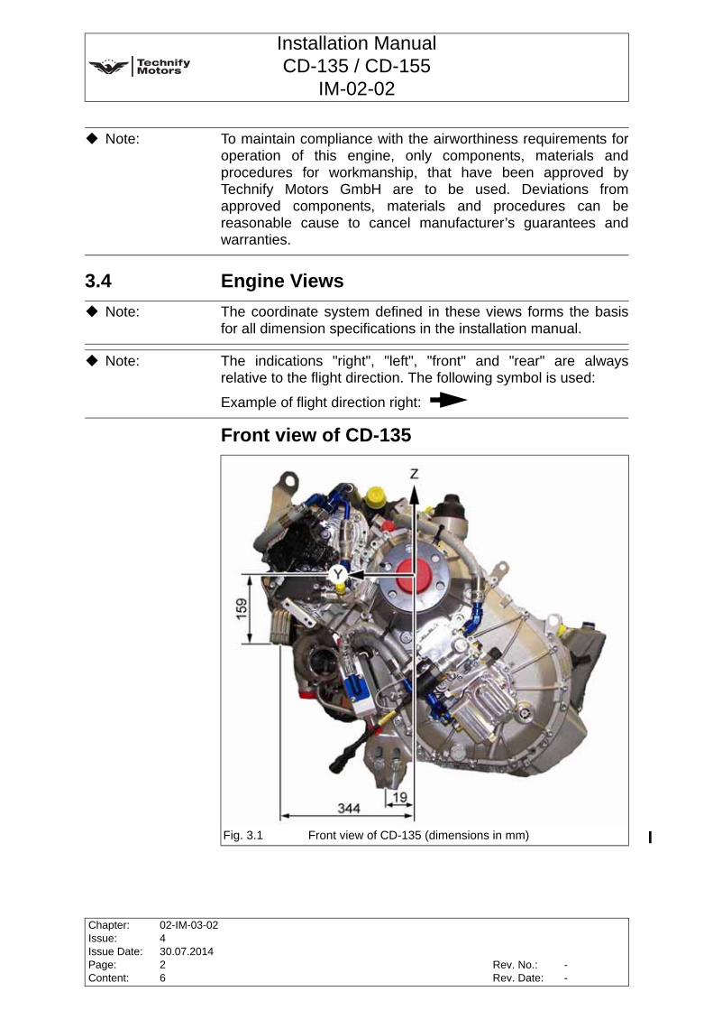
3.4 Engine Views
Front view of CD-135
Note: To maintain compliance with the airworthiness requirements foroperation of this engine, only components, materials andprocedures for workmanship, that have been approved byTechnify Motors GmbH are to be used. Deviations fromapproved components, materials and procedures can bereasonable cause to cancel manufacturer’s guarantees andwarranties.
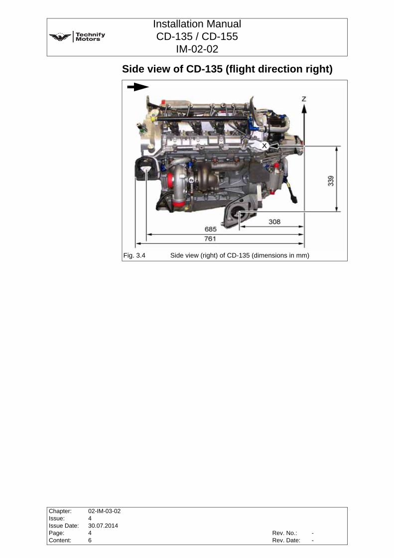
Note: The coordinate system defined in these views forms the basisfor all dimension specifications in the installation manual.
Note: The indications "right", "left", "front" and "rear" are alwaysrelative to the flight direction. The following symbol is used:
Example of flight direction right:
Fig. 3.1 Front view of CD-135 (dimensions in mm)
Chapter:Issue:Issue Date:Page:Content:
02-IM-03-02430.07.201426
Rev. No.:Rev. Date:
--

Installation ManualCD-135 / CD-155
IM-02-02
Top view of CD-135
Side view of CD-135 (flight direction left)
Fig. 3.2 Top view of CD-135 (dimensions in mm)
Fig. 3.3 Side view (left) of CD-135 (dimensions in mm)
X
Rev. No.:Rev. Date:
Chapter:Issue:Issue Date:Page:Content:
02-IM-03-02430.07.201436
--
Installation ManualCD-135 / CD-155
IM-02-02
Side view of CD-135 (flight direction right)
Fig. 3.4 Side view (right) of CD-135 (dimensions in mm)
Chapter:Issue:Issue Date:Page:Content:
02-IM-03-02430.07.201446
Rev. No.:Rev. Date:
--
Installation ManualCD-135 / CD-155
IM-02-02
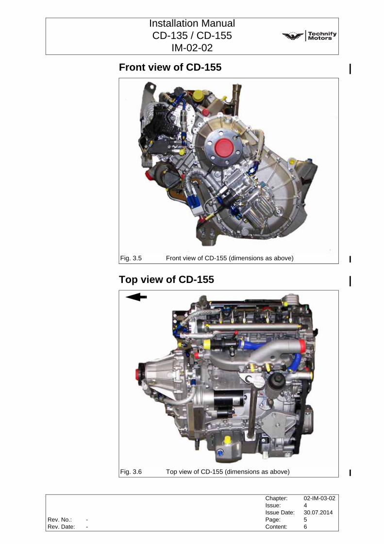
Front view of CD-155
Top view of CD-155
Fig. 3.5 Front view of CD-155 (dimensions as above)
Fig. 3.6 Top view of CD-155 (dimensions as above)
Rev. No.:Rev. Date:
Chapter:Issue:Issue Date:Page:Content:
02-IM-03-02430.07.201456
--
Installation ManualCD-135 / CD-155
IM-02-02
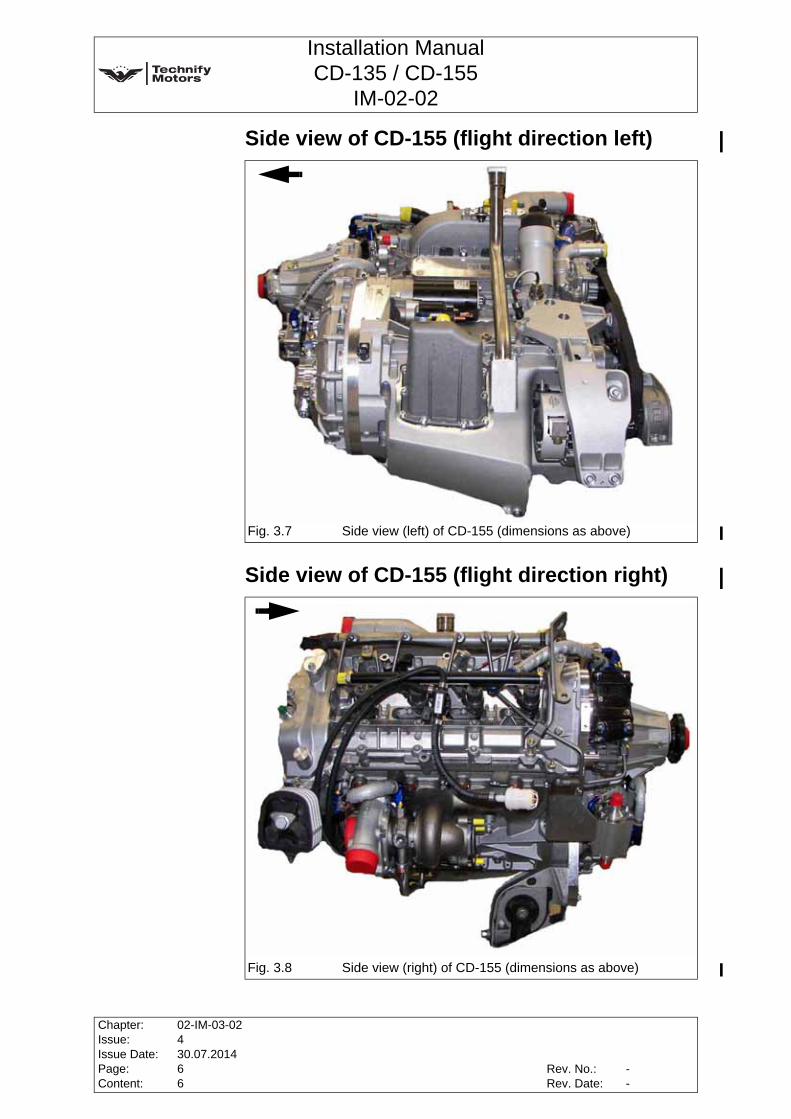
Side view of CD-155 (flight direction left)
Side view of CD-155 (flight direction right)
Fig. 3.7 Side view (left) of CD-155 (dimensions as above)
Fig. 3.8 Side view (right) of CD-155 (dimensions as above)
X
Chapter:Issue:Issue Date:Page:Content:
02-IM-03-02430.07.201466
Rev. No.:Rev. Date:
--
Installation ManualCD-135 / CD-155
IM-02-02
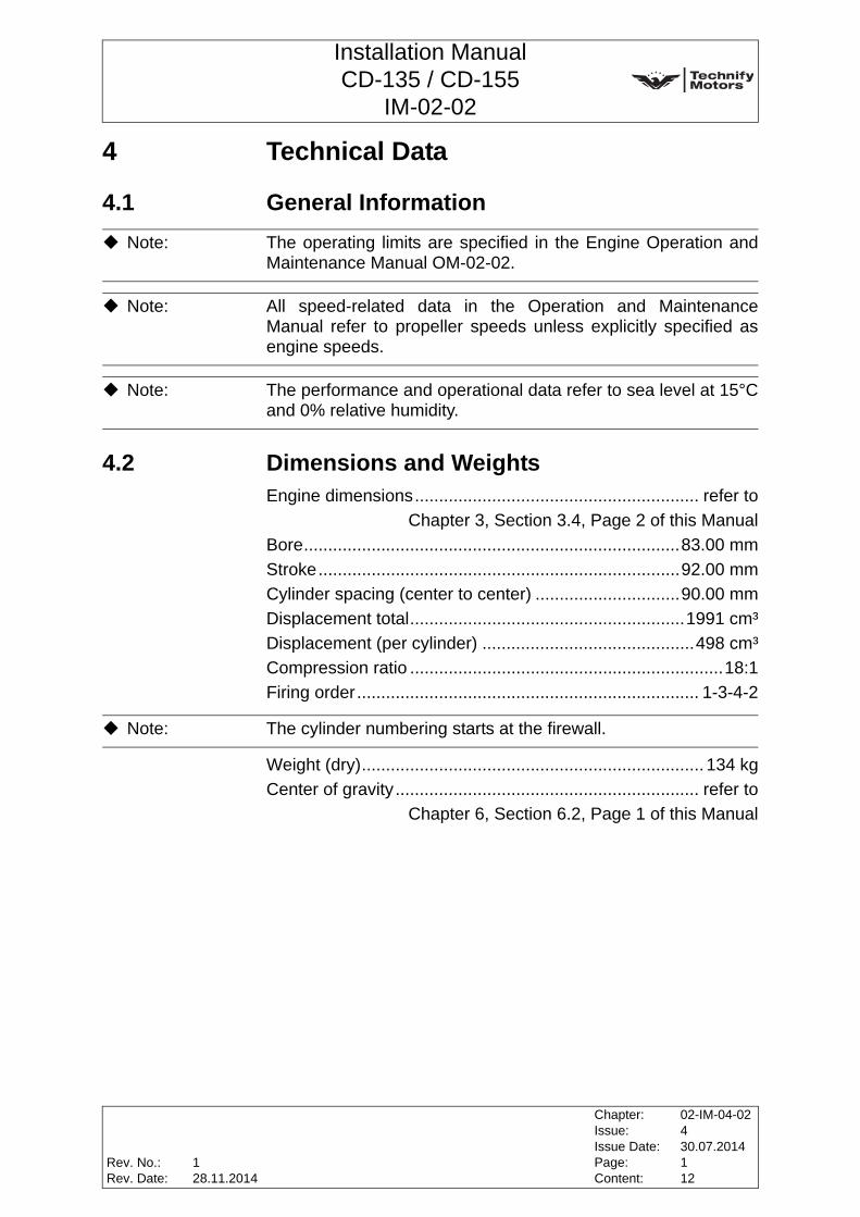
4 Technical Data
4.1 General Information
4.2 Dimensions and WeightsEngine dimensions........................................................... refer to
Chapter 3, Section 3.4, Page 2 of this ManualBore..............................................................................83.00 mmStroke...........................................................................92.00 mmCylinder spacing (center to center) ..............................90.00 mmDisplacement total.........................................................1991 cm³Displacement (per cylinder) ............................................498 cm³Compression ratio .................................................................18:1Firing order....................................................................... 1-3-4-2
Weight (dry)....................................................................... 134 kgCenter of gravity............................................................... refer to
Chapter 6, Section 6.2, Page 1 of this Manual
Note: The operating limits are specified in the Engine Operation andMaintenance Manual OM-02-02.
Note: All speed-related data in the Operation and MaintenanceManual refer to propeller speeds unless explicitly specified asengine speeds.
Note: The performance and operational data refer to sea level at 15°Cand 0% relative humidity.
Note: The cylinder numbering starts at the firewall.
Rev. No.:Rev. Date:
Chapter:Issue:Issue Date:Page:Content:
02-IM-04-02430.07.2014112
128.11.2014
Installation ManualCD-135 / CD-155
IM-02-02
4.3 Engine and Gearbox Data
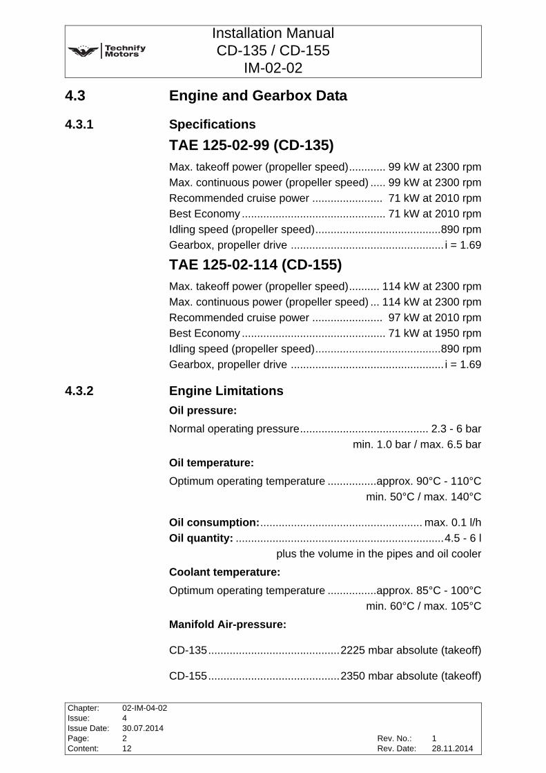
4.3.1 SpecificationsTAE 125-02-99 (CD-135)Max. takeoff power (propeller speed)............ 99 kW at 2300 rpmMax. continuous power (propeller speed) ..... 99 kW at 2300 rpmRecommended cruise power ....................... 71 kW at 2010 rpmBest Economy ............................................... 71 kW at 2010 rpmIdling speed (propeller speed).........................................890 rpmGearbox, propeller drive .................................................. i = 1.69
TAE 125-02-114 (CD-155)Max. takeoff power (propeller speed).......... 114 kW at 2300 rpmMax. continuous power (propeller speed) ... 114 kW at 2300 rpmRecommended cruise power ....................... 97 kW at 2010 rpmBest Economy ............................................... 71 kW at 1950 rpmIdling speed (propeller speed).........................................890 rpmGearbox, propeller drive .................................................. i = 1.69
4.3.2 Engine LimitationsOil pressure:Normal operating pressure.......................................... 2.3 - 6 bar
min. 1.0 bar / max. 6.5 bar
Oil temperature:Optimum operating temperature ................approx. 90°C - 110°C
min. 50°C / max. 140°C
Oil consumption:..................................................... max. 0.1 l/hOil quantity: ....................................................................4.5 - 6 l
plus the volume in the pipes and oil cooler
Coolant temperature:Optimum operating temperature ................approx. 85°C - 100°C
min. 60°C / max. 105°C
Manifold Air-pressure:
CD-135...........................................2225 mbar absolute (takeoff)
CD-155...........................................2350 mbar absolute (takeoff)
Chapter:Issue:Issue Date:Page:Content:
02-IM-04-02430.07.2014212
Rev. No.:Rev. Date:
128.11.2014
Installation ManualCD-135 / CD-155
IM-02-02
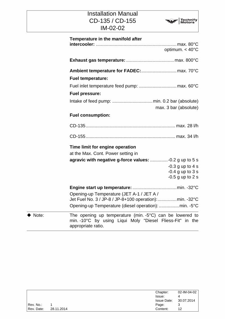
Temperature in the manifold after intercooler: ................................................................max. 80°C
optimum. < 40°C
Exhaust gas temperature: ......................................max. 800°C
Ambient temperature for FADEC:............................max. 70°C
Fuel temperature:Fuel inlet temperature feed pump: ..............................max. 60°C
Fuel pressure:Intake of feed pump: ................................min. 0.2 bar (absolute)
max. 3 bar (absolute)
Fuel consumption:
CD-135....................................................................... max. 28 l/h
CD-155....................................................................... max. 34 l/h
Time limit for engine operation at the Max. Cont. Power setting inagravic with negative g-force values: ..............-0.2 g up to 5 s
-0.3 g up to 4 s-0.4 g up to 3 s-0.5 g up to 2 s
Engine start up temperature: ...................................min. -32°COpening-up Temperature (JET A-1 / JET A / Jet Fuel No. 3 / JP-8 / JP-8+100 operation):...............min. -32°COpening-up Temperature (diesel operation): ................min. -5°C
Note: The opening up temperature (min. -5°C) can be lowered tomin. -10°C by using Liqui Moly "Diesel Fliess-Fit" in theappropriate ratio.
Rev. No.:Rev. Date:
Chapter:Issue:Issue Date:Page:Content:
02-IM-04-02430.07.2014312
128.11.2014

Installation ManualCD-135 / CD-155
IM-02-02
Banking (rotations deviating from the apparent perpendicular):
Around the x-axis ..................................................... max. +/- 15°Around the y-axis ..................................................... max. +/- 15°Around the z-axis ....................................................... max. +/- 5°
Gearbox oil filling quantity:................................... approx. 1.2 l
Fig. 4.1 Banking
Note: Up to these deviations from the apparent perpendicular, properlubrication is ensured.
Chapter:Issue:Issue Date:Page:Content:
02-IM-04-02430.07.2014412
Rev. No.:Rev. Date:
128.11.2014
Installation ManualCD-135 / CD-155
IM-02-02
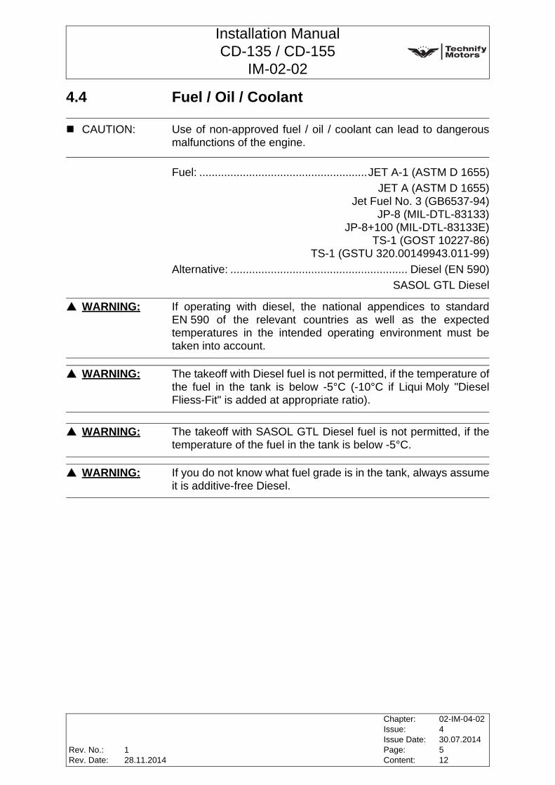
4.4 Fuel / Oil / Coolant
Fuel: ......................................................JET A-1 (ASTM D 1655)JET A (ASTM D 1655)
Jet Fuel No. 3 (GB6537-94)JP-8 (MIL-DTL-83133)
JP-8+100 (MIL-DTL-83133E)TS-1 (GOST 10227-86)
TS-1 (GSTU 320.00149943.011-99)Alternative: ......................................................... Diesel (EN 590)
SASOL GTL Diesel
CAUTION: Use of non-approved fuel / oil / coolant can lead to dangerousmalfunctions of the engine.
WARNING: If operating with diesel, the national appendices to standardEN 590 of the relevant countries as well as the expectedtemperatures in the intended operating environment must betaken into account.
WARNING: The takeoff with Diesel fuel is not permitted, if the temperature ofthe fuel in the tank is below -5°C (-10°C if Liqui Moly "DieselFliess-Fit" is added at appropriate ratio).
WARNING: The takeoff with SASOL GTL Diesel fuel is not permitted, if thetemperature of the fuel in the tank is below -5°C.
WARNING: If you do not know what fuel grade is in the tank, always assumeit is additive-free Diesel.
Rev. No.:Rev. Date:
Chapter:Issue:Issue Date:Page:Content:
02-IM-04-02430.07.2014512
128.11.2014
Installation ManualCD-135 / CD-155
IM-02-02
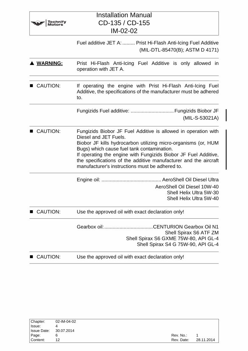
Fuel additive JET A: ......... Prist Hi-Flash Anti-Icing Fuel Additive(MIL-DTL-85470(B); ASTM D 4171)
Fungizids Fuel additive: ...............................Fungizids Biobor JF(MIL-S-53021A)
Engine oil: ........................................... AeroShell Oil Diesel UltraAeroShell Oil Diesel 10W-40
Shell Helix Ultra 5W-30Shell Helix Ultra 5W-40
Gearbox oil: ...................................CENTURION Gearbox Oil N1Shell Spirax S6 ATF ZM
Shell Spirax S6 GXME 75W-80, API GL-4Shell Spirax S4 G 75W-90, API GL-4
WARNING: Prist Hi-Flash Anti-Icing Fuel Additive is only allowed inoperation with JET A.
CAUTION: If operating the engine with Prist Hi-Flash Anti-Icing FuelAdditive, the specifications of the manufacturer must be adheredto.
CAUTION: Fungizids Biobor JF Fuel Additive is allowed in operation withDiesel and JET Fuels.Biobor JF kills hydrocarbon utilizing micro-organisms (or, HUMBugs) which cause fuel tank contamination.If operating the engine with Fungizids Biobor JF Fuel Additive,the specifications of the additive manufacturer and the aircraftmanufacturer's instructions must be adhered to.
CAUTION: Use the approved oil with exact declaration only!
CAUTION: Use the approved oil with exact declaration only!
Chapter:Issue:Issue Date:Page:Content:
02-IM-04-02430.07.2014612
Rev. No.:Rev. Date:
128.11.2014

Installation ManualCD-135 / CD-155
IM-02-02
Coolant: ..........Water / radiator protection mixed at ratio of 50:50
Radiator protection............... BASF Glysantin Protect Plus / G48Valvoline / Zerex Glysantin G48
BASF Glysantin Alu Protect / G30Valvoline / Zerex Glysantin G30
BASF Glysantin Protect / G05Valvoline / Zerex Glysantin G05
Mobil Antifreeze Extra (G48)Comma Xstream Green - Concentrate (G48)
WARNING: No coolant loss may occur during operation! Any coolant lossmust immediately be followed by a technical inspection whichhas to be carried out by an authorized person. Engine damagecould result from coolant loss and this could cause enginefailure.
WARNING: If the ice flocculation point of the coolant is outside the specifiedrange, the full anti-corrosion and anti-freeze protection ispossibly not guaranteed.
CAUTION: Glysantin G05, Glysantin G30 and Glysantin G48 must not bemixed with each other.
CAUTION: Operation with Glysantin G30 is only permitted without silicatepouch.
CAUTION: Operation with Glysantin G05 or Glysantin G48 is only permittedwith silicate pouch.
CAUTION: Exchange between the coolants Glysantin G30 and GlysantinG05 / Glysantin G48 is not permitted without an alternation ofthe installation.
CAUTION: The exchange to the respectively other approved coolantdemands the installation or demounting of the silicate pouch,this depends on the used coolant. Observe the other cautionnotes of this section.
Rev. No.:Rev. Date:
Chapter:Issue:Issue Date:Page:Content:
02-IM-04-02430.07.2014712
128.11.2014

Installation ManualCD-135 / CD-155
IM-02-02
CAUTION: The water must meet the following requirements:1. Visual appearance: colorless, clear, no deposits allowed2. pH-value: 6.5 to 8.53. Water hardness: max. 2.7 mmol/l4. Hydrogen carbonate: max. 100 mg/l5. Chloride concentration: max. 100 mg/l6. Sulfate concentration: max. 100 mg/l
Note: It is recommended to use Glysantin Protect Plus Ready-Mix andGlysantin Alu Protect Ready-Mix respectively to ensure propercoolant quality.
Note: The ice floccuation point of the coolant is -38°C, if mixed 50:50.Glysantin G48 is an anti-corrosion and anti-freeze additive. Theice flocculation point must be -38°C +/-2°C. If the freezing pointis outside this range the coolant has to be exchanged.
Chapter:Issue:Issue Date:Page:Content:
02-IM-04-02430.07.2014812
Rev. No.:Rev. Date:
128.11.2014
Installation ManualCD-135 / CD-155
IM-02-02
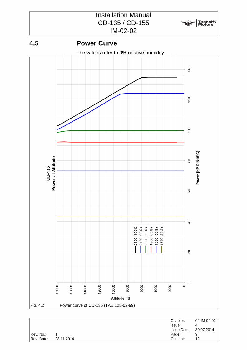
4.5 Power CurveThe values refer to 0% relative humidity.
Fig. 4.2 Power curve of CD-135 (TAE 125-02-99)
CD
-135
Pow
er a
t Alti
tude
0
2000
4000
6000
8000
1000
0
1200
0
1400
0
1600
0
1800
0
020
4060
8010
012
014
0
Pow
er [H
P D
IN15
°C]
Altitude [ft]
2300
(100
%)
2180
(90%
)20
30 (7
5%)
1960
(65%
)18
80 (5
0%)
1750
(25%
)
Rev. No.:Rev. Date:
Chapter:Issue:Issue Date:Page:Content:
02-IM-04-02430.07.2014912
128.11.2014

Installation ManualCD-135 / CD-155
IM-02-02
Fig. 4.3 Power curve of CD-155 (TAE 125-02-114)
CD
-155
Pow
er a
t Alti
tude
0
2000
4000
6000
8000
1000
0
1200
0
1400
0
1600
0
1800
0
2000
0
2200
0
2400
0
020
4060
8010
012
014
0
Pow
er [H
P D
IN15
°C]
Altitude [ft]
2300
(100
%)
2180
(90%
)20
30 (7
5%)
1960
(65%
)18
80 (5
0%)
1750
(25%
)
Chapter:Issue:Issue Date:Page:Content:
02-IM-04-02430.07.20141012
Rev. No.:Rev. Date:
128.11.2014

Installation ManualCD-135 / CD-155
IM-02-02
4.6 Low Temperature Data and Climate Classes of Diesel in Europe
Note: The officially published values in EN 590 must be observed.
Note: The minimum opening-up fuel temperature in the tank can belowered from -5°C to -10°C if Liqui Moly "Diesel Fliess-Fit" isadded according to the application and dose specifications ofLiqui Moly.
Rev. No.:Rev. Date:
Chapter:Issue:Issue Date:Page:Content:
02-IM-04-02430.07.20141112
128.11.2014

Installation ManualCD-135 / CD-155
IM-02-02
This page intentionally left blank
Chapter:Issue:Issue Date:Page:Content:
02-IM-04-02430.07.20141212
Rev. No.:Rev. Date:
128.11.2014

Installation ManualCD-135 / CD-155
IM-02-02
5 Transport and Packaging
5.1 PackagingThe engine has been packaged at the factory for transport asfollows:
• Mounted on a support in a wooden crate.
5.2 Transport• The engine may only be lifted by the transport eyelets
(see Fig. 5.1, Fig. 5.2 and Fig. 5.3).
• The lifting device used must be suitable for the weight of the engine.
Note: The packaging should be kept for reuse in a possible futureshipment.
Fig. 5.1 Lifting eyelet at gearbox
Rev. No.:Rev. Date:
Chapter:Issue:Issue Date:Page:Content:
02-IM-05-02430.07.201414
128.11.2014

Installation ManualCD-135 / CD-155
IM-02-02
Note: Demount the lifting eyelet at the cylinder head cover(see Fig. 5.2) after installing the engine to the engine mount.
Fig. 5.2 Lifting eyelet at cylinder head cover
Fig. 5.3 Lifting eyelet at cylinder head
1
Note: A suitable container should be built for transport. A drawing for building a suitable transport container or thetransport container itself can be purchased from Technify MotorsGmbH.
Chapter:Issue:Issue Date:Page:Content:
02-IM-05-02430.07.201424
Rev. No.:Rev. Date:
128.11.2014
Installation ManualCD-135 / CD-155
IM-02-02
5.3 Protective CoversAll engine openings are protected against ingress of dirt andmoisture.
5.4 Preservation of the Engine
WARNING: The protective covers are only intended for transport andinstallation. All protective covers shall be removed before takingthe engine into operation, even for testing purposes.
Note: It is advisable to remove the protective plugs just before theinstallation of the individual feed lines.
Note: The transport equipment and protective plugs should beretained. If the engine has to be returned to the manufacturer ata later date, the transport equipment and protective plugs mustbe used.
Note: See OM-02-02, Chapter 1, Section 1.8 for further information.
Rev. No.:Rev. Date:
Chapter:Issue:Issue Date:Page:Content:
02-IM-05-02430.07.201434
128.11.2014

Installation ManualCD-135 / CD-155
IM-02-02
This page intentionally left blank
Chapter:Issue:Issue Date:Page:Content:
02-IM-05-02430.07.201444
Rev. No.:Rev. Date:
128.11.2014

Installation ManualCD-135 / CD-155
IM-02-02
6 Engine Mounting and Installation Position
6.1 General
6.2 Center of Gravity of the Enginex-coordinate of the center of gravity [mm):................. X = 369.64y-coordinate of the center of gravity [mm]: ................. Y = -17.01z-coordinate of the center of gravity [mm]: ................. Z = -90.23
WARNING: The engine must be mounted on all three engine mountingpoints.
CAUTION: The installation of the engine must be performed in a safe andcontrolled manner at all times. Please take into account the totalweight of the engine.
Note: Applicability of the components from the aircraft manufacturershall be made sure in accordance with JAR 23, FAR 23 andCS 23.
WARNING: Consider that the center of gravity of the overall installation willbe shifted with the installation of the propeller and other auxiliaryequipment which is not part of the engine's scope of supply.
Note: The location of the center of gravity of the dry engine is given inrelation to the propeller flange. For information about thecoordinate system refer to Chapter 3, Section 3.4, Page 2 of thisManual.
Rev. No.:Rev. Date:
Chapter:Issue:Issue Date:Page:Content:
02-IM-06-02430.07.201414
--
Installation ManualCD-135 / CD-155
IM-02-02
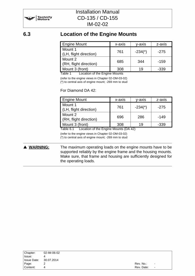
6.3 Location of the Engine Mounts
Table 1 Location of the Engine Mounts(refer to the engine views in Chapter 02-OM-03-02)(*) to central axis of engine mount; -269 mm to stud
For Diamond DA 42:
Table 6.1 Location of the Engine Mounts (DA 42)(refer to the engine views in Chapter 02-OM-03-02)(*) to central axis of engine mount; -269 mm to stud
Engine Mount x-axis y-axis z-axisMount 1(LH, flight direction) 761 -234(*) -275
Mount 2(RH, flight direction) 685 344 -159
Mount 3 (front) 308 19 -339
Engine Mount x-axis y-axis z-axisMount 1(LH, flight direction) 761 -234(*) -275
Mount 2(RH, flight direction) 696 286 -149
Mount 3 (front) 308 19 -339
WARNING: The maximum operating loads on the engine mounts have to besupported reliably by the engine frame and the housing mounts.Make sure, that frame and housing are sufficiently designed forthe operating loads.
Chapter:Issue:Issue Date:Page:Content:
02-IM-06-02430.07.201424
Rev. No.:Rev. Date:
--

Installation ManualCD-135 / CD-155
IM-02-02
6.4 Permissible Loads at the Engine Mounts
Table 6.2 Maximum loads permitted at the engine mounts [kN]
6.5 Permissible Installation PositionsThis engine is only designed for pull propeller installations. The propeller shaft must lie above the crankshaft and pointtowards the front in the direction of flight (x-axis). The installationposition of the engine is given by the definition of the enginemounts (refer to 6.3, Page 2 of this Chapter). Deviations from thisposition are possible within a range defined by a rotation aroundthe x-axis by +14°/-2°, the y-axis by +5°/0° and around the z-axis(vertical axis) by ±5°, or as a combination of these rotations.
WARNING: All engine mounting bolts must be tightened to the tighteningtorque specified in the aircraft manufacturer's instructions. Only the approved mounting bolts must be used.
CAUTION: The proof of compliance for certification of the engine frame andthe housing mounts according to the applicable certificationrequirements like JAR and FAR has to be shown by the aircraftor airframe manufacturer. Only approved engine frames must beused.
Engine bearings +X -X +Y -Y +Z -ZBearing 1 - 7.9 2.7 2.7 4.7 4.0Bearing 2 - 3.2 1.1 1.1 1.9 1.6Bearing 3 - 10.8 3.6 3.6 6.4 5.4
Rev. No.:Rev. Date:
Chapter:Issue:Issue Date:Page:Content:
02-IM-06-02430.07.201434
--
Installation ManualCD-135 / CD-155
IM-02-02
6.6 General Information on Engine Mounting• To isolate vibrations, the supplied shock mounts must be
installed between engine and airframe.
WARNING: In any cases, the engine mount must be tested with ground runsrelated to vibration behaviour and with static tests to theprescribed loads. The proof of compliance for certification of theengine frame and the housing mounts according to theapplicable certification requirements like JAR and FAR has to beshown by the aircraft or airframe manufacturer. Only tested and approved engine mounts must be used. Theuse of unsuitable engine mounts can cause serious damage tothe engine and airframe or even cause the aircraft to crash.
Note: The engine mount must be designed to avoid excessive enginevibrations, excessive noise and vibrations from the airframeside.
Chapter:Issue:Issue Date:Page:Content:
02-IM-06-02430.07.201444
Rev. No.:Rev. Date:
--

Installation ManualCD-135 / CD-155
IM-02-02
7 Exhaust System
7.1 General
7.2 Design of the Exhaust SystemThe design and installation of the exhaust system is determinedmainly by the available space for installing it in the aircraft.Interface is the turbocharger and the integral manifold. Twodifferent versions of turbochargers are possible,K16 turbocharger or V22 turbocharger (older version). Integralmanifold depends on the aircraft and the turbocharger version.
Permissible forces and moments affecting the exhaust flange:Max. permissible forces in the x, y and z-directions........ 300 NmMax. permissible bending momentsin the x- and y-directions .................................................. 2.5 NmMax. permissible bending moment in the z-direction ........ 10 Nm
Note: Applicability of the components from the aircraft manufacturershall be made sure in accordance with JAR 23, FAR 23 andCS 23.
WARNING: EXTREME FIRE HAZARD! The exhaust system must be installed in such a way that there isno risk of any aircraft or engine components being ignited orinflamed.
CAUTION: No kinks in the exhaust system are allowed. Unnecessary bendshave to be avoided.
WARNING: If possible, the exhaust pipe should not be supported byadditional mountings. If additional support is unavoidable, thenthe exhaust pipe must be attached with the aid of compensator'sdue to different vibrations of engine and engine mount.
Rev. No.:Rev. Date:
Chapter:Issue:Issue Date:Page:Content:
02-IM-07-02430.07.201414
--
Installation ManualCD-135 / CD-155
IM-02-02
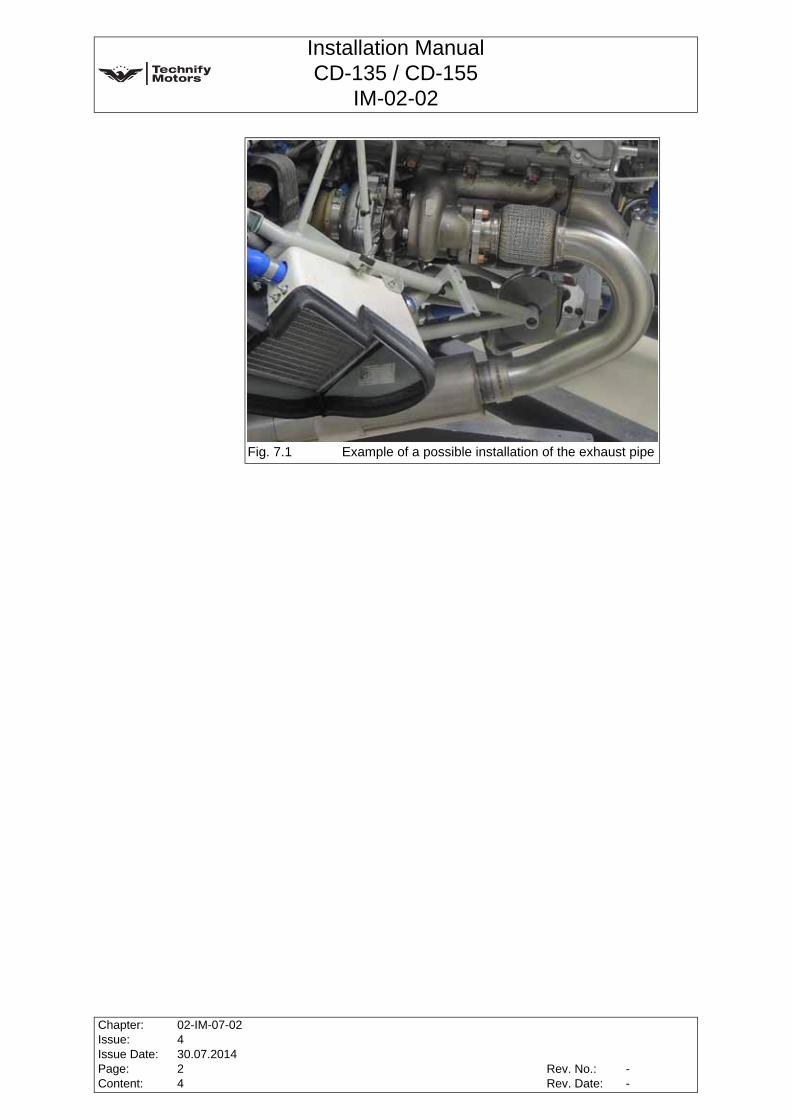
Fig. 7.1 Example of a possible installation of the exhaust pipe
Chapter:Issue:Issue Date:Page:Content:
02-IM-07-02430.07.201424
Rev. No.:Rev. Date:
--

Installation ManualCD-135 / CD-155
IM-02-02
7.3 Requirements for the Exhaust SystemA muffler is not required.Back pressure at maximum power: ..........................max. 0.1 barAn inner diameter of 57 mm of the exhaust pipe is recommended.
7.4 General Information on the Exhaust SystemA frequent cause for vibrations on the exhaust system isimproper installation and maintenance. With regard to the airframe installation situation, on the airframeside an additional protection of the exhaust system with vibrationdamping elements shall be provided. Installation of a heater, using the exhaust pipe, is not permitted. The engine has a connection for a water heat exchanger.
WARNING: The exhaust system must have a minimum temperatureresistance of 800°C!
CAUTION: HOT SURFACE! Due to occurring high temperatures, avoid contact with hotsurfaces by wearing appropriate protective clothing.
CAUTION: The exhaust system has to be secured appropriately accordingto its installation position.
CAUTION: The surroundings of the turbocharger and the exhaust systemshould be protected with suitable heat shields.
WARNING: Excessive tension at exhaust system mounting points couldcause cracks and be a potential fire hazard!
Rev. No.:Rev. Date:
Chapter:Issue:Issue Date:Page:Content:
02-IM-07-02430.07.201434
--

Installation ManualCD-135 / CD-155
IM-02-02
This page intentionally left blank
Chapter:Issue:Issue Date:Page:Content:
02-IM-07-02430.07.201444
Rev. No.:Rev. Date:
--
Installation ManualCD-135 / CD-155
IM-02-02
8 Cooling System
8.1 General
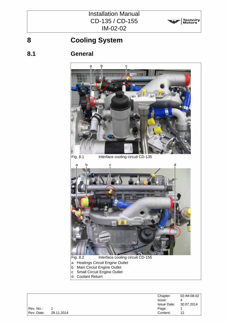
Fig. 8.1 Interface cooling circuit CD-135
Fig. 8.2 Interface cooling circuit CD-155a Heatings Circuit Engine Outletb Main Circiut Engine Outletc Small Circuit Engine Outletd Coolant Return
b ca
ba c d
Rev. No.:Rev. Date:
Chapter:Issue:Issue Date:Page:Content:
02-IM-08-02430.07.2014112
128.11.2014

Installation ManualCD-135 / CD-155
IM-02-02
The following components are not part of the scope of supply, butare required for installation:
• Water Cooler
• Coolant hoses
• Expansion Tank
• Cartridge provided with silicate pouch (order number for silicate pouch: P/N 40-7520-H0024xx)
Note: Applicability of the components from the aircraft manufacturershall be made sure in accordance with JAR 23, FAR 23 andCS 23.
Note: The expansion tank has got an integrated coolant level sensor.
Note: The the silicate pouch needs to be changed every 3000 hours orat least every 6 years.
Chapter:Issue:Issue Date:Page:Content:
02-IM-08-02430.07.2014212
Rev. No.:Rev. Date:
128.11.2014

Installation ManualCD-135 / CD-155
IM-02-02
8.2 Requirements for the Cooling System
Coolant hoses:Temperature stability:...................................min. -40°C to 140°CPressure durability: ......................................................min. 3 barInner diameter: ................................. min. 25 mm to max. 34 mmMaterial: ....................................... 3-layer silicone 100% suitable
for glycol and antifreeze.Ensure resistance to ozone.
WARNING: The coolant system must ensure that the engine operating limitsare not exceeded.
WARNING: There must be no loss of coolant during operation. Any coolantloss must be rectified immediately. Risk of engine damage!
CAUTION: Secure all hoses and hose connections against slipping.
CAUTION: Ensure that all tubes and tube connections of the coolant systemshow no leakage at all.
CAUTION: Only suitable and standardized hoses, clamps and tubes may beused.
CAUTION: The welding directives for aviation must be observed. Weldingwork must only be performed by specially trained and certifiedpersonnel.
Note: The use of hose clamps which comply with ABA 265 DIN isrecommended.
Note: Instead of longer hoses use aluminum tubes (inner diameter ofmin. Ø25 mm to max. Ø34 mm).
Rev. No.:Rev. Date:
Chapter:Issue:Issue Date:Page:Content:
02-IM-08-02430.07.2014312
128.11.2014
Installation ManualCD-135 / CD-155
IM-02-02
Water Cooler:Temperature stability:...................................min. -40°C to 140°CPressure durability: ......................................................min. 3 barCooling power CD-135:..............................................min. 31 kWCooling power CD-155:..............................................min. 52 kWVolume flow:............... min. 90 l/min at 3900 rpm (engine speed)
and 99kW/114kW (max. power)Max. pressure Δ: ........................................... 0.25 bar at 90 l/min
Expansion Tank:Temperature stability:...................................min. -40°C to 140°CPressure durability: ......................................................min. 3 barMaterial: ....................................................100% suited for glycol
and anti-freeze.Ensure resistance to ozone.
Expansion volume:...............................min. 1 Liter of which 50%is residual air (with cold coolant)
Chapter:Issue:Issue Date:Page:Content:
02-IM-08-02430.07.2014412
Rev. No.:Rev. Date:
128.11.2014
Installation ManualCD-135 / CD-155
IM-02-02
8.3 Dimension and Location of Connections
Bleed line
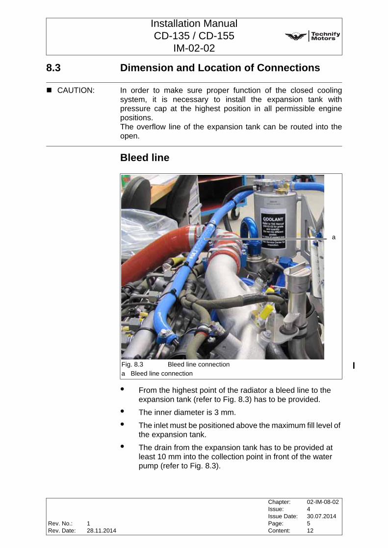
• From the highest point of the radiator a bleed line to the expansion tank (refer to Fig. 8.3) has to be provided.
• The inner diameter is 3 mm.
• The inlet must be positioned above the maximum fill level of the expansion tank.
• The drain from the expansion tank has to be provided at least 10 mm into the collection point in front of the water pump (refer to Fig. 8.3).
CAUTION: In order to make sure proper function of the closed coolingsystem, it is necessary to install the expansion tank withpressure cap at the highest position in all permissible enginepositions. The overflow line of the expansion tank can be routed into theopen.
Fig. 8.3 Bleed line connectiona Bleed line connection
a
Rev. No.:Rev. Date:
Chapter:Issue:Issue Date:Page:Content:
02-IM-08-02430.07.2014512
128.11.2014
Installation ManualCD-135 / CD-155
IM-02-02
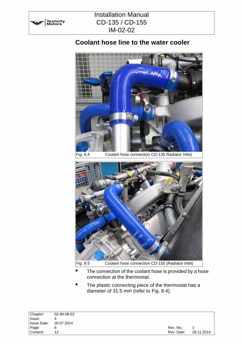
Coolant hose line to the water cooler
• The connection of the coolant hose is provided by a hose connection at the thermostat.
• The plastic connecting piece of the thermostat has a diameter of 31.5 mm (refer to Fig. 8.4).
Fig. 8.4 Coolant hose connection CD-135 Radiator Inlet)
Fig. 8.5 Coolant hose connection CD-155 (Radiator Inlet)
1
Chapter:Issue:Issue Date:Page:Content:
02-IM-08-02430.07.2014612
Rev. No.:Rev. Date:
128.11.2014
Installation ManualCD-135 / CD-155
IM-02-02
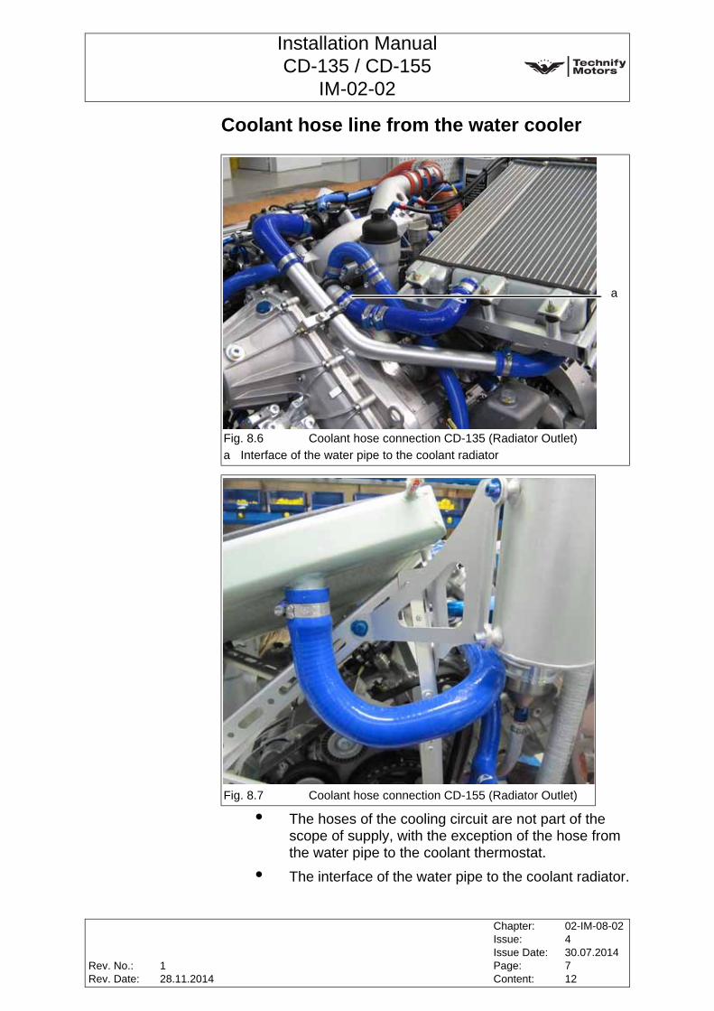
Coolant hose line from the water cooler
• The hoses of the cooling circuit are not part of the scope of supply, with the exception of the hose from the water pipe to the coolant thermostat.
• The interface of the water pipe to the coolant radiator.
Fig. 8.6 Coolant hose connection CD-135 (Radiator Outlet)a Interface of the water pipe to the coolant radiator
Fig. 8.7 Coolant hose connection CD-155 (Radiator Outlet)
1
2
1a
Rev. No.:Rev. Date:
Chapter:Issue:Issue Date:Page:Content:
02-IM-08-02430.07.2014712
128.11.2014
Installation ManualCD-135 / CD-155
IM-02-02
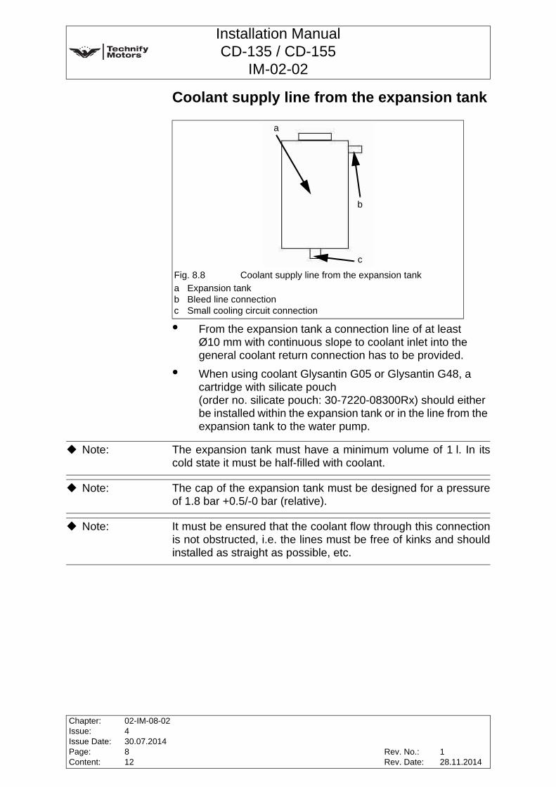
Coolant supply line from the expansion tank
• From the expansion tank a connection line of at least Ø10 mm with continuous slope to coolant inlet into the general coolant return connection has to be provided.
• When using coolant Glysantin G05 or Glysantin G48, a cartridge with silicate pouch(order no. silicate pouch: 30-7220-08300Rx) should either be installed within the expansion tank or in the line from the expansion tank to the water pump.
Fig. 8.8 Coolant supply line from the expansion tanka Expansion tankb Bleed line connectionc Small cooling circuit connection
a
b
c
Note: The expansion tank must have a minimum volume of 1 l. In itscold state it must be half-filled with coolant.
Note: The cap of the expansion tank must be designed for a pressureof 1.8 bar +0.5/-0 bar (relative).
Note: It must be ensured that the coolant flow through this connectionis not obstructed, i.e. the lines must be free of kinks and shouldinstalled as straight as possible, etc.
Chapter:Issue:Issue Date:Page:Content:
02-IM-08-02430.07.2014812
Rev. No.:Rev. Date:
128.11.2014
Installation ManualCD-135 / CD-155
IM-02-02
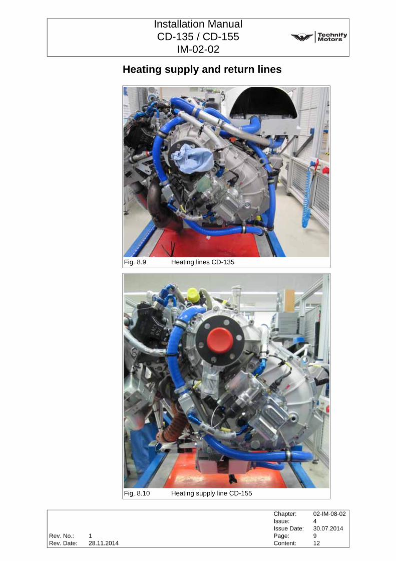
Heating supply and return lines
Fig. 8.9 Heating lines CD-135
Fig. 8.10 Heating supply line CD-155
1
Rev. No.:Rev. Date:
Chapter:Issue:Issue Date:Page:Content:
02-IM-08-02430.07.2014912
128.11.2014
Installation ManualCD-135 / CD-155
IM-02-02
A heat exchanger can be connected to the engine serving as aheating unit. The heating water feed shall be taken from the upper thermostatconnection. See Fig. 8.3.The plastic connection piece on the thermostat has an outerdiameter of 8 mm (with beaded rim 12 mm).
The CD-155 version uses an additional gearbox oil heatexchanger, which heats and cools the gearbox oil. See Fig. 8.10.
The heating return has to be fed into the general coolant returnconnection in the water pump intake on the engine side.
8.4 CoolantCoolant: ............................................ Water / Radiator Protection
refer toChapter 4, Section 4.4, Page 5 of this Manual
WARNING: If the ice flocculation point of the coolant is outside the specifiedrange, the full anti-corrosion and anti-freeze protection ispossibly not guaranteed.
CAUTION: The exchange to the respectively other approved coolantdemands the installation or demounting of the silicate pouch,this depends on the used coolant. Observe the other cautionnotes of this section.
CAUTION: The water must meet the following requirements:1. Visual appearance: colorless, clear, no deposits allowed2. pH-value: 6.5 to 8.53. Water hardness: max. 2.7 mmol/l4. Hydrogen carbonate: max. 100 mg/l5. Chloride concentration: max. 100 mg/l6. Sulfate concentration: max. 100 mg/l
Note: It is recommended to use Glysantin Protect Plus Ready-Mix andGlysantin Alu Protect Ready-Mix respectively to ensure propercoolant quality.
Note: The ice floccuation point of the coolant is -38°C, if mixed 50:50.Glysantin G48 is an anti-corrosion and anti-freeze additive. Theice flocculation point must be -38°C +/-2°C. If the freezing pointis outside this range the coolant has to be exchanged.
Chapter:Issue:Issue Date:Page:Content:
02-IM-08-02430.07.20141012
Rev. No.:Rev. Date:
128.11.2014

Installation ManualCD-135 / CD-155
IM-02-02
8.5 General Information about the Coolant SystemThe proof of compliance for certification of the required coolantsystem components according to the applicable requirementslike JAR, FAR or CS has to be accomplished by the aircraft orairframe manufacturer. The suitability of materials used in the coolant system has to beshown within this proof.
8.6 Display Instrument:Requirements and ConnectionsWater temperature sensor and a appropriate display instru-ment• The display instrument is not part of the scope of supply.
• The display instrument must have color ranges as shown inTable 1.
Table 1
• The display accuracy at lower limit of the red range 105°C, respectively 221°F, must be ±5°C or better, respectively ±9°F or better.
• Data can be taken from the CAN connector of the ECU. Related information can be obtained via Technify Motors GmbH.
Coolant Temperature Color Ranges
ColorRange
DescriptionMin in °C
Max in °C
Min in °F
Max in °F
Amber -32 60 -26 140 LowGreen 60 101 140 213 NormalAmber >101 105 >213 221 HighRed >105 115 >221 240 Very High
Note: Technify Motors GmbH offers a certified engine display tomonitor all relevant engine parameters.The order no. is 02-7730-5501-()-() which can be used tomonitor all of the engine parameters. This display is certified inaccordance with JTSO-C113 by the Luftfahrt-Bundesamt.
Rev. No.:Rev. Date:
Chapter:Issue:Issue Date:Page:Content:
02-IM-08-02430.07.20141112
128.11.2014
Installation ManualCD-135 / CD-155
IM-02-02
8.7 Inspection of the Coolant SystemThe coolant system has to be inspected after installation asfollows:
• Perform a pressure test with a minimum pressure of 3.0 bar (absolute) and 2.0 bar over pressure. Duration: 2 minutes. Afterwards check for leakage (refer to the aircraft manufacturers specification).
• Finally, the tightness is checked with the engine test run.
• Check the ethylene glycol concentration of the coolant.
Note: The coolant level may not decrease.
Chapter:Issue:Issue Date:Page:Content:
02-IM-08-02430.07.20141212
Rev. No.:Rev. Date:
128.11.2014

Installation ManualCD-135 / CD-155
IM-02-02
9 Cooling Air Duct System
9.1 General
The engine is equipped with a coolant system with a cooling airduct system. A sufficient supply of cooling air to the radiator and intercooler isvital for the operation of the engine.
9.2 Requirements for the Cooling Air Duct SystemThe cooling air duct system has to be designed to make sure thatthe permissible surface temperatures of the individualcomponents are not exceeded. The regulations of the aircraft manufacturer and the supervisoryauthorities must be observed.
Note: Applicability of the components from the aircraft manufacturershall be made sure in accordance with JAR 23, FAR 23 andCS 23.
ComponentMaximum permissible surface / cooling air
temperatureBelt drive (belt, crankshaft vibration dampers and pulleys) 85°C
Oil filter (o-ring) 140°C
Alternator
107°COn the metal housing, or the
air inlet temperaturedepending on altitude (refer
to the diagram in Fig. 9.1)Starter 85°CElectrical plug-in connections, wires and sensors 85°C
Engine shock mounts (rubber) 80°CInjectors 110°CVacuum line to the turbocharger 85°C
Vacuum regulator 85°CCoolant thermostat housing 105°CCoolant hoses 105°CGearbox (bearings and seals to the clutch) 120°C
Rev. No.:Rev. Date:
Chapter:Issue:Issue Date:Page:Content:
02-IM-09-02430.07.201412
--

Installation ManualCD-135 / CD-155
IM-02-02
Drain hose beneath the high-pressure pump 80°C
Fuel lines 80°CFADEC -45°C - +70°C
ComponentMaximum permissible surface / cooling air
temperature
CAUTION: The cooling air duct system has to be designed to make surethat the permissible operating temperatures (refer to Chapter 4,Section 4.3, Page 2 of this Manual) and the maximumcomponent temperatures are not exceeded under anycircumstances (refer to table above).
Fig. 9.1 Air inlet temperature diagram
GeneratorMaximum air inlet temperature for a 90A load
0,0
10,0
20,0
30,0
40,0
50,0
60,0
70,0
0 5 10 15 20 25 30
Altitude[1000 ft]
Max
imum
air
inle
t tem
pera
ture
[°
C] Maximum air inlet
temperature
Chapter:Issue:Issue Date:Page:Content:
02-IM-09-02430.07.201422
Rev. No.:Rev. Date:
--

Installation ManualCD-135 / CD-155
IM-02-02
10 Lubricating System
10.1 General
10.2 Requirements for the Lubricating System (CD-135 only)
Note: Applicability of the components from the aircraft manufacturershall be ensured in accordance with JAR 23, FAR 23 and CS 23.
Fig. 10.1 Oil System Schematic with Blowby
Note: The CD-155 version is equipped with an integrated oil-waterheat exchanger.
CAUTION: The installations must be designed to ensure that thepermissible operating temperatures are not exceeded.
Rev. No.:Rev. Date:
Chapter:Issue:Issue Date:Page:Content:
02-IM-10-02430.07.201418
--

Installation ManualCD-135 / CD-155
IM-02-02
Oil cooler:Temperature stability:.................................................min. 150°CPressure durability: ....................................................min. 10 barCooling power: ............................................min. 10 kW at 99 kW
min. 13 kW at 114 kWVolume flow: ............ min. 14 l / min at 3900 rpm (engine speed)
and at 99 kW (max. power)min. 20 l / min at 3900 rpm (engine speed)
and at 114 kW (max. power)Max pressure Δ: ............................................ 0.55 bar at 14 l/min
Oil lines to oil cooler:Temperature stability:.................................................min. 150°CPressure durability: ....................................................min. 10 barBending radius: ......................................................... min. 40 mmOil line diameter: ......................... adequate to the corresponding
Dash 10 connections..
Crankcase breather line:Blowby crankcase breather: ..................................... max. 200 l/hTemperature stability:.................................................min. 150°CPressure durability: ......................................................min. 7 bar
WARNING: A reduction of the diameter over the whole length of the line isnot permitted. Refer to Section 10.4, Page 4 of this Chapter for hose lengths.
WARNING: If the diameter of the oil line is too small, this could cause anengine damage.
CAUTION: Only standardized lines and connections which are approved forthis purpose may be used.
CAUTION: Care should be taken to ensure that no suction is developed inthe lubricating system.
Chapter:Issue:Issue Date:Page:Content:
02-IM-10-02430.07.201428
Rev. No.:Rev. Date:
--

Installation ManualCD-135 / CD-155
IM-02-02
10.3 Integrated Oil Separator (CD-135 only)As an option, the CD-155 Lubrication System can have aninternal centrifugal oil separator located in the cylinder head.If no mechanical vacuum pump is installed the centrifugal oilseparator is located in this position.In this case the blowby and the blowby hoses are omitted.
Fig. 10.2 Oil System Schematic with Integrated Oil Separator
Fig. 10.3 Integrated Oil Separator
Rev. No.:Rev. Date:
Chapter:Issue:Issue Date:Page:Content:
02-IM-10-02430.07.201438
--

Installation ManualCD-135 / CD-155
IM-02-02
10.4 Connections: Dimensions, Location and Length of Hoses
10.4.1 Breather crankcase
The blowby connection shall be conducted with Dash12 at the oilpan and shall be fed into the blowby oil separator, then the oilreturned to the oil pan.The blowby (discharge) should be lead outside of the cowling. The hose lengths must be within the following tolerance range:Dash12 discharge hose: .........................................min. 300 mm
max. 2000 mmDash12 inlet hose: ..................................................min. 300 mm
max. 1500 mmHose, oil return to turbocharger (Dash06):..............min. 500 mm
max. 2000 mm
Fig. 10.4 Breather crankcase CD-135 and CD-155a Blowby inletb Blowby dischargec Blowby return
c
a b
Chapter:Issue:Issue Date:Page:Content:
02-IM-10-02430.07.201448
Rev. No.:Rev. Date:
--

Installation ManualCD-135 / CD-155
IM-02-02
Tightening torques for the Dash connections:Dash06 (Aluminum) .................................................. min. 17 Nm
max. 22 NmDash06 (Stainless Steel)........................................... min. 24 Nm
max. 32 NmDash12 (Aluminum) .................................................. min. 52 Nm
max. 62 NmDash12 (Stainless Steel)........................................... min. 97 Nm
max. 112 Nm
Note: The tightening torque of aluminum will be used on differentpaired materials.
Note: Technify Motors GmbH offers an appropriate oil separator underthe P/N 02-7250-18100Rx, P/N 50-7250-H0016xx andP/N 05-7254-K0002xx.
Rev. No.:Rev. Date:
Chapter:Issue:Issue Date:Page:Content:
02-IM-10-02430.07.201458
--
Installation ManualCD-135 / CD-155
IM-02-02
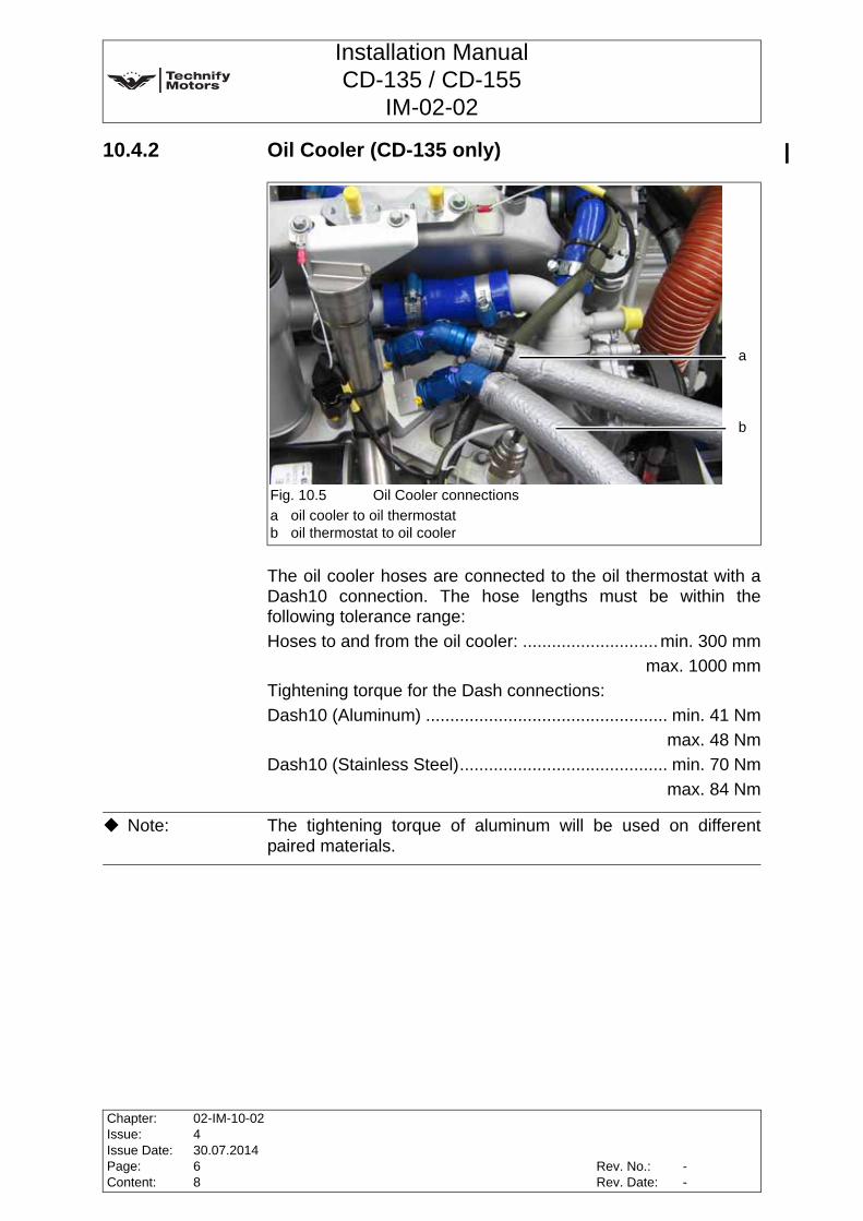
10.4.2 Oil Cooler (CD-135 only)
The oil cooler hoses are connected to the oil thermostat with aDash10 connection. The hose lengths must be within thefollowing tolerance range:Hoses to and from the oil cooler: ............................min. 300 mm
max. 1000 mmTightening torque for the Dash connections:Dash10 (Aluminum) .................................................. min. 41 Nm
max. 48 NmDash10 (Stainless Steel)........................................... min. 70 Nm
max. 84 Nm
Fig. 10.5 Oil Cooler connectionsa oil cooler to oil thermostatb oil thermostat to oil cooler
b
a
Note: The tightening torque of aluminum will be used on differentpaired materials.
Chapter:Issue:Issue Date:Page:Content:
02-IM-10-02430.07.201468
Rev. No.:Rev. Date:
--
Installation ManualCD-135 / CD-155
IM-02-02
10.5 Display Instruments:Requirements and Connections
10.5.1 Requirements for the display instrument
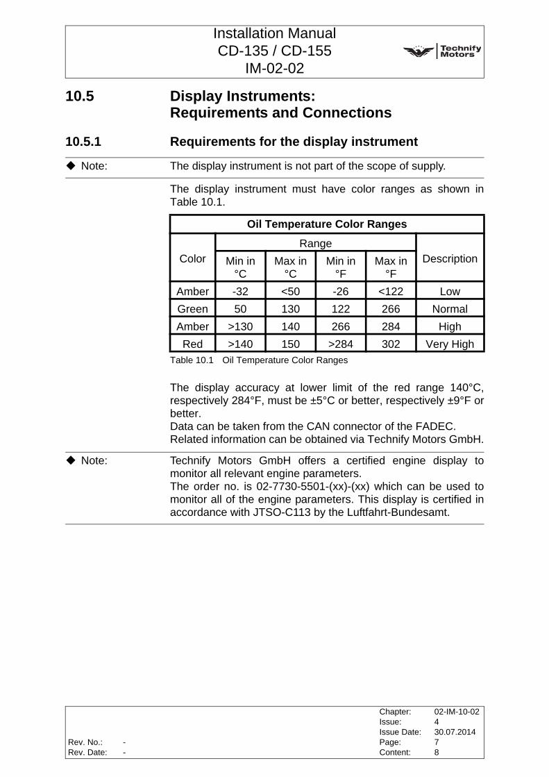
The display instrument must have color ranges as shown inTable 10.1.
Table 10.1 Oil Temperature Color Ranges
The display accuracy at lower limit of the red range 140°C,respectively 284°F, must be ±5°C or better, respectively ±9°F orbetter.Data can be taken from the CAN connector of the FADEC. Related information can be obtained via Technify Motors GmbH.
Note: The display instrument is not part of the scope of supply.
Oil Temperature Color Ranges
ColorRange
DescriptionMin in °C
Max in °C
Min in °F
Max in °F
Amber -32 <50 -26 <122 LowGreen 50 130 122 266 NormalAmber >130 140 266 284 HighRed >140 150 >284 302 Very High
Note: Technify Motors GmbH offers a certified engine display tomonitor all relevant engine parameters.The order no. is 02-7730-5501-(xx)-(xx) which can be used tomonitor all of the engine parameters. This display is certified inaccordance with JTSO-C113 by the Luftfahrt-Bundesamt.
Rev. No.:Rev. Date:
Chapter:Issue:Issue Date:Page:Content:
02-IM-10-02430.07.201478
--
Installation ManualCD-135 / CD-155
IM-02-02
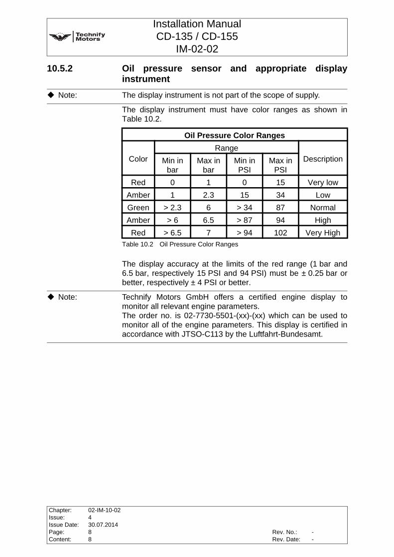
10.5.2 Oil pressure sensor and appropriate displayinstrument
The display instrument must have color ranges as shown inTable 10.2.
Table 10.2 Oil Pressure Color Ranges
The display accuracy at the limits of the red range (1 bar and6.5 bar, respectively 15 PSI and 94 PSI) must be ± 0.25 bar orbetter, respectively ± 4 PSI or better.
Note: The display instrument is not part of the scope of supply.
Oil Pressure Color Ranges
ColorRange
DescriptionMin in bar
Max in bar
Min in PSI
Max in PSI
Red 0 1 0 15 Very lowAmber 1 2.3 15 34 LowGreen > 2.3 6 > 34 87 NormalAmber > 6 6.5 > 87 94 HighRed > 6.5 7 > 94 102 Very High
Note: Technify Motors GmbH offers a certified engine display tomonitor all relevant engine parameters.The order no. is 02-7730-5501-(xx)-(xx) which can be used tomonitor all of the engine parameters. This display is certified inaccordance with JTSO-C113 by the Luftfahrt-Bundesamt.
Chapter:Issue:Issue Date:Page:Content:
02-IM-10-02430.07.201488
Rev. No.:Rev. Date:
--
Installation ManualCD-135 / CD-155
IM-02-02
11 Fuel System
11.1 General
The scope of supply of the engine includes the following:
• the fuel pumps operated by the engine and
• the injection system including the collecting return lines.
The fuel feed line from the tank to the suction connection of thefeed pump operated by the engine and the return line to the tankare not a part of the scope of supply. This scope consists of the following components:
• Tank
• Fuel filter
• Water separator
• Fuel shut-off valve
• Additional electrical pump
• Tank thermometer with sensor
• Required fuel lines and connections
Note: Applicability of the components from the aircraft manufacturershall be ensured in accordance with JAR 23, FAR 23 and CS 23.
WARNING: If leaks appear and air penetrates into the fuel system, the fuelpumps and the injection system could be damaged.
WARNING: When installing the individual components of the fuel system,ensure absolute cleanliness. Running the fuel pumps dry candamage them.
CAUTION: The proof of compliance for certification of the componentswhich are not included in the scope of supply according to theapplicable requirements like JAR, FAR or CS has to beaccomplished by the aircraft or airframe manufacturer.
Rev. No.:Rev. Date:
Chapter:Issue:Issue Date:Page:Content:
02-IM-11-02430.07.201418
--
Installation ManualCD-135 / CD-155
IM-02-02
11.2 Requirements for the Fuel System
11.2.1 General information
The complete fuel system must be designed for a temperaturerange from -40°C to +120°C.
Fuel heating at a reference temperature of 25°C* Engine speed** Joule / second = Watt
The fuel inlet temperature at the feed pump is limited tomax. 60°C. The aircraft fuel system must be designed, that there is aminimum absolute pressure of 675 mbar (absolute) at sea levelat the intake of the feed pump at all engine operating points. In all permissible flight attitudes up to the maximum operatingaltitude the fuel pressure at the intake of the feed pump must beat least 200 mbar (absolute).When using additional pumps, a maximum absolute pressure of3 bar must not be exceeded at the intake of the feed pump.Fuel pressure (intake of feed pump): ........................min. 0.2 bar
(absolute at maximum-load andat the maximum service ceiling)
min. 675 mbar (absolute at MSL)max. 3 bar
WARNING: The fuel system must be designed, that all operating limits areobserved.
Rotational speed [rpm]*
Load Return volume[l/min]
Max. quantity of heat [J/s]**
1500 Idle 1.45 302
3400 max. Load 1.90 1758
3900 max. Load 1.92 1976
Chapter:Issue:Issue Date:Page:Content:
02-IM-11-02430.07.201428
Rev. No.:Rev. Date:
--

Installation ManualCD-135 / CD-155
IM-02-02
11.2.2 Lines
Pumping capacity: ..................................................... min. 150 l/hin any approved flight altitude
from MSL up to service ceilingFuel lines: ....................................................min. diameter 5 mm
The entire fuel system must be designed to be "Fire-Resistant" asa minimum. In the event of fire, it must be ensured that fuel cannot be pumpedinto the designated fire zone (engine compartment). Accordingly,it must be possible to shut off the feed and return line. This canbe done for example with a combined fuel shut-off valve.
11.2.3 Drain moduleThe fuel system must be designed in a way, that all points wherecondensation water and contamination could collect, can bedrained. Within the fuel system, the drain module has to be the lowestpoint.
WARNING: All of the aircraft's fuel lines must be pressure resistant. Thepressure resistance value depends upon the fuel system of theaircraft. If only the engine's own pumps are used, the aircraft'sfuel lines have to be designed for a compression strength of2 bar.
WARNING: The fuel lines have to be installed away from hot enginecomponents without kinks and protected appropriately, sinceotherwise fire hazard exists.
CAUTION: Only hoses, lines and joints approved for aviation purposes maybe used.
WARNING: The drain module must be designed to allow drainage ofcondensation water within the fuel system as part of the dailypre-flight check.
Rev. No.:Rev. Date:
Chapter:Issue:Issue Date:Page:Content:
02-IM-11-02430.07.201438
--
Installation ManualCD-135 / CD-155
IM-02-02
11.2.4 Fuel filter moduleThe fuel filter has to be selected, that even after 60 hours of solidcontaminated fuel operation according to MIL 5007D and10 hours of water contaminated fuel operation under icingconditions according to CS-E 670 there is sufficient fuel for safeengine operation. The fuel filter module has to be exchangedaccording to Chapter 6 of OM-02-02, check also Chapter 5 ofOM-02-02 if applicable. Should the exchange interval beextended, appropriate validation must be accomplished.
Fuel filter:Filter surface: ........................................................min. 4000 cm2
MFP:...............................................................................11±2 µm
11.2.5 Combined drain and fuel filter module (Technify Motors GmbH)Technify Motors GmbH offers a combined drain and fuel filtermodule which has been certified for the specified requirements.The appropriate fuel filter module and element can be ordered atTechnify Motors GmbH. For further information please contactTechnify Motors GmbH.
WARNING: The thermostat-controlled combined drain and fuel filter module(Technify Motors GmbH) must be at least 30 cm below the feedpump level!Continuous filter systems which are not multi-way systems canbe installed max. 15 cm above the feed pump level.
Chapter:Issue:Issue Date:Page:Content:
02-IM-11-02430.07.201448
Rev. No.:Rev. Date:
--
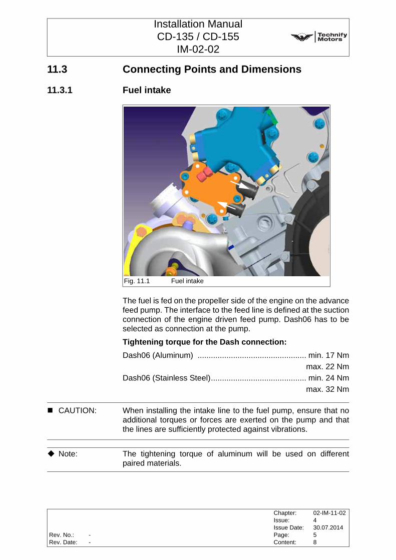
Installation ManualCD-135 / CD-155
IM-02-02
11.3 Connecting Points and Dimensions
11.3.1 Fuel intake
The fuel is fed on the propeller side of the engine on the advancefeed pump. The interface to the feed line is defined at the suctionconnection of the engine driven feed pump. Dash06 has to beselected as connection at the pump.
Tightening torque for the Dash connection:Dash06 (Aluminum) ................................................. min. 17 Nm
max. 22 NmDash06 (Stainless Steel)........................................... min. 24 Nm
max. 32 Nm
Fig. 11.1 Fuel intake
CAUTION: When installing the intake line to the fuel pump, ensure that noadditional torques or forces are exerted on the pump and thatthe lines are sufficiently protected against vibrations.
Note: The tightening torque of aluminum will be used on differentpaired materials.
Rev. No.:Rev. Date:
Chapter:Issue:Issue Date:Page:Content:
02-IM-11-02430.07.201458
--
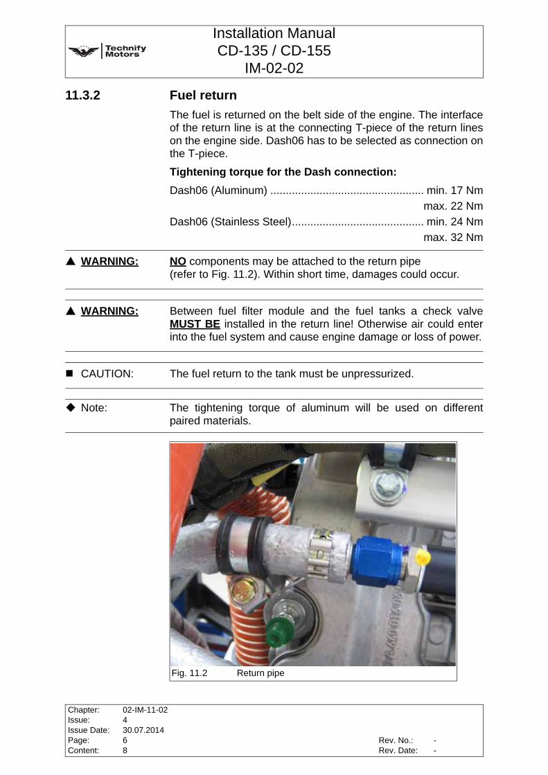
Installation ManualCD-135 / CD-155
IM-02-02
11.3.2 Fuel returnThe fuel is returned on the belt side of the engine. The interfaceof the return line is at the connecting T-piece of the return lineson the engine side. Dash06 has to be selected as connection onthe T-piece.
Tightening torque for the Dash connection:Dash06 (Aluminum) .................................................. min. 17 Nm
max. 22 NmDash06 (Stainless Steel)........................................... min. 24 Nm
max. 32 Nm
WARNING: NO components may be attached to the return pipe(refer to Fig. 11.2). Within short time, damages could occur.
WARNING: Between fuel filter module and the fuel tanks a check valveMUST BE installed in the return line! Otherwise air could enterinto the fuel system and cause engine damage or loss of power.
CAUTION: The fuel return to the tank must be unpressurized.
Note: The tightening torque of aluminum will be used on differentpaired materials.
Fig. 11.2 Return pipe
Chapter:Issue:Issue Date:Page:Content:
02-IM-11-02430.07.201468
Rev. No.:Rev. Date:
--

Installation ManualCD-135 / CD-155
IM-02-02
11.4 Display Instrument:Requirements and ConnectionsTank temperature sensor and an appropriate display instrumentSensor and instrument are not included in the scope of supply.The display instrument must have color ranges as shown inTable 11.1.
Table 11.1 Fuel Temperature Output Color Ranges
The operating limits for operation with JET A-1 / JET A / Jet FuelNo. 3 / JP-8 / JP-8+100 fuel must be readable. The sensors must be appropriate for this measuring range andfor use with JET A-1 / JET A / Jet Fuel No.3 / JP-8 / JP-8+100fuel.
Fuel Temperature Output Color Ranges
ColorRange
DescriptionMin in °C
Max in °C
Min in °F
Max in °F
Red X < -50 < -58 InvalidRed < -50 -30 -58 -22 Very low
Amber < -30 -5 < -22 24 LowWhite -5 65 24 148 NormalAmber > 65 75 > 148 166 HighRed > 75 100 > 166 212 Very High
Red X > 100 > 212 Invalid
Note: The overall accuracy on the red lines must not exceed ±5°C,respectively ±9°F.
Note: The lower operating limit for the engine at -30°C only applies toJET A-1 / JET A / Jet Fuel No.3 / JP-8 / JP-8+100 operation. Ifan aircraft is licensed for Diesel operation, the operating limit forfuel temperature from -5°C on may not be exceeded. In thiscase, appropriate placards should be mounted on the tanks andinstrument panel to inform the pilot.
Note: When determining the minimum tank temperature for take-offwith the aircraft, the country-specific and seasonal differencesfor Diesel mixtures must be considered.
Rev. No.:Rev. Date:
Chapter:Issue:Issue Date:Page:Content:
02-IM-11-02430.07.201478
--

Installation ManualCD-135 / CD-155
IM-02-02
This page intentionally left blank
Chapter:Issue:Issue Date:Page:Content:
02-IM-11-02430.07.201488
Rev. No.:Rev. Date:
--
Installation ManualCD-135 / CD-155
IM-02-02
12 Intake System
12.1 General
An air filter and charge air intercooler should be supplied for theintake system as they are not included in the scope of supply ofthe engine.
12.2 Intake System Requirements
12.2.1 Air filterA minimum air flow rate of 8 m3/min must be guaranteed underall conditions.
For example, the air filter with the P/N NM-0000-01728xx orP/N 30-7160-13120Rx (older part) meets these requirements.
12.2.2 Intercooler
It is recommended that the intercooler must be configured in away, that the intake air temperature is no more than 25K abovethe ambient air temperature, both during Vy-climb and at levelflight. At maximum power (take-off / max. continuous) the airmass flow rate is9 kg / min, which requires a required cooling performance of16 kW.Max. pressure Δ (intercooler) ..................... 0.07 bar at 9 kg / minMax. manifold air temperature: .........................................100°CMax. manifold air temperature for 100% engine power: ......60°C
Note: Applicability of the components from the aircraft manufacturershall be made sure in accordance with JAR 23, FAR 23 andCS 23.
CAUTION: The filter elements must not seal up if they come into contactwith water.
WARNING: An intercooler is required to cool down the intake air that heatsup during the compression process of the turbocharger. If theintercooler does not achieve the necessary cooling, the engineloses its performance.
Rev. No.:Rev. Date:
Chapter:Issue:Issue Date:Page:Content:
02-IM-12-02430.07.201416
--
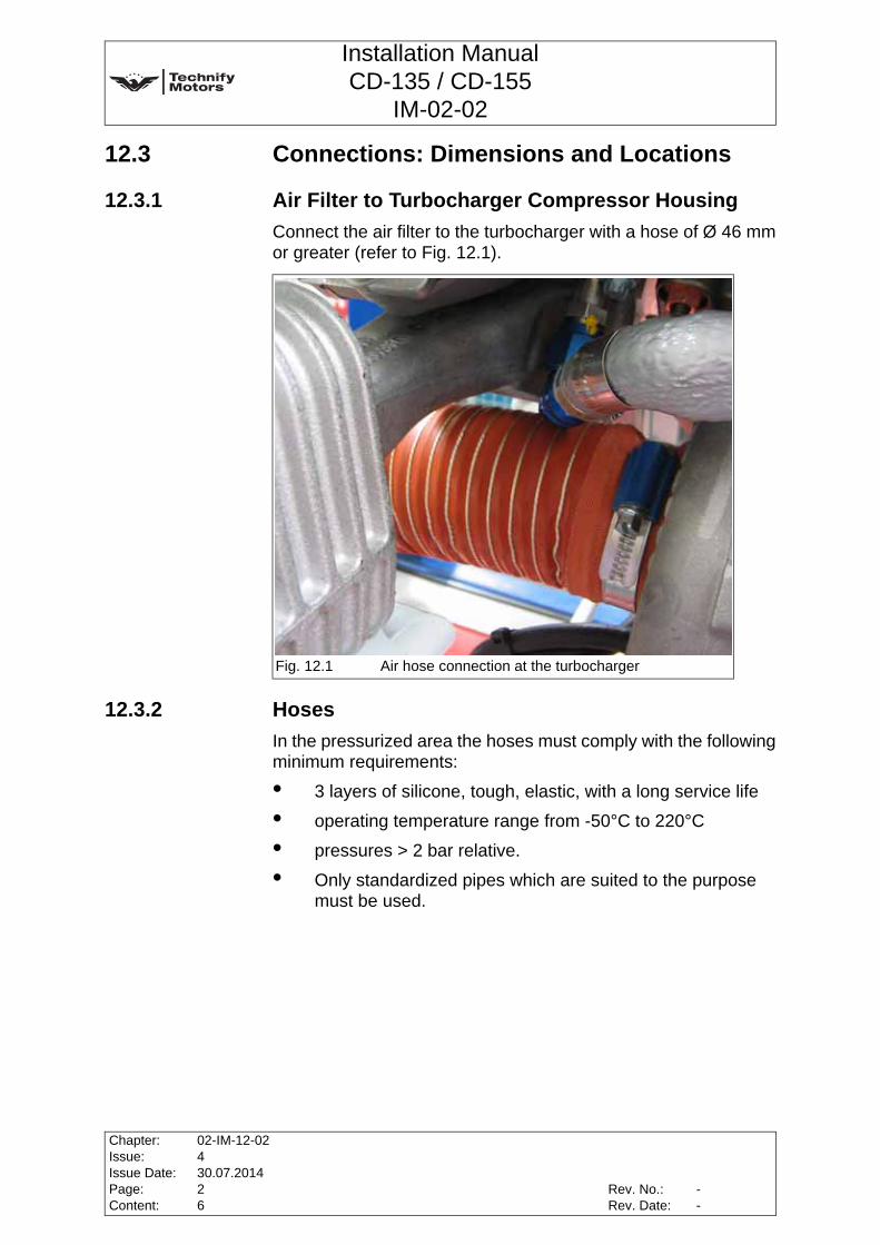
Installation ManualCD-135 / CD-155
IM-02-02
12.3 Connections: Dimensions and Locations
12.3.1 Air Filter to Turbocharger Compressor HousingConnect the air filter to the turbocharger with a hose of Ø 46 mmor greater (refer to Fig. 12.1).
12.3.2 HosesIn the pressurized area the hoses must comply with the followingminimum requirements:
• 3 layers of silicone, tough, elastic, with a long service life
• operating temperature range from -50°C to 220°C
• pressures > 2 bar relative.
• Only standardized pipes which are suited to the purpose must be used.
Fig. 12.1 Air hose connection at the turbocharger
Chapter:Issue:Issue Date:Page:Content:
02-IM-12-02430.07.201426
Rev. No.:Rev. Date:
--
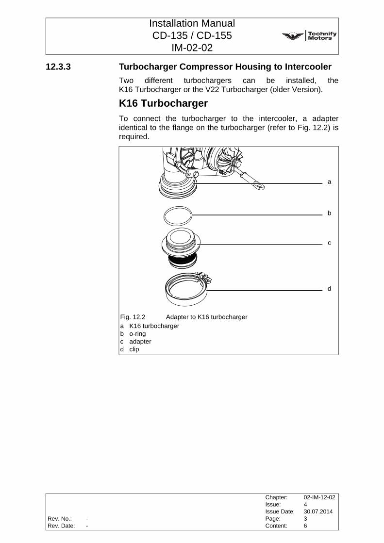
Installation ManualCD-135 / CD-155
IM-02-02
12.3.3 Turbocharger Compressor Housing to IntercoolerTwo different turbochargers can be installed, theK16 Turbocharger or the V22 Turbocharger (older Version).
K16 TurbochargerTo connect the turbocharger to the intercooler, a adapteridentical to the flange on the turbocharger (refer to Fig. 12.2) isrequired.
Fig. 12.2 Adapter to K16 turbochargera K16 turbochargerb o-ringc adapterd clip
b
a
c
d
Rev. No.:Rev. Date:
Chapter:Issue:Issue Date:Page:Content:
02-IM-12-02430.07.201436
--
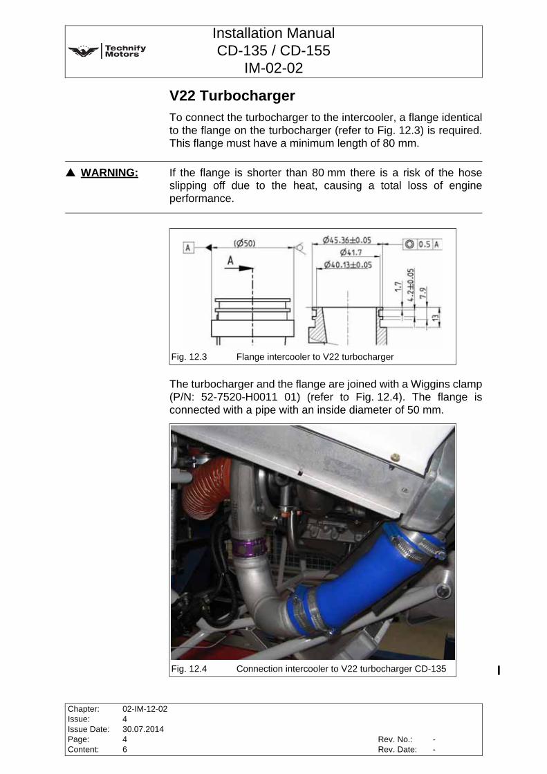
Installation ManualCD-135 / CD-155
IM-02-02
V22 TurbochargerTo connect the turbocharger to the intercooler, a flange identicalto the flange on the turbocharger (refer to Fig. 12.3) is required.This flange must have a minimum length of 80 mm.
The turbocharger and the flange are joined with a Wiggins clamp(P/N: 52-7520-H0011 01) (refer to Fig. 12.4). The flange isconnected with a pipe with an inside diameter of 50 mm.
WARNING: If the flange is shorter than 80 mm there is a risk of the hoseslipping off due to the heat, causing a total loss of engineperformance.
Fig. 12.3 Flange intercooler to V22 turbocharger
Fig. 12.4 Connection intercooler to V22 turbocharger CD-135
Chapter:Issue:Issue Date:Page:Content:
02-IM-12-02430.07.201446
Rev. No.:Rev. Date:
--

Installation ManualCD-135 / CD-155
IM-02-02
The intercooler is connected to the intake manifold with a hose ofmin. Ø 48 mm (refer to Fig. 12.6).
Fig. 12.5 Connection intercooler to V22 turbocharger CD-155
Fig. 12.6 Connection intercooler to intake manifold
2
1
CAUTION: Only standardized and approved lines and connections must beused.
Rev. No.:Rev. Date:
Chapter:Issue:Issue Date:Page:Content:
02-IM-12-02430.07.201456
--
Installation ManualCD-135 / CD-155
IM-02-02
This page intentionally left blank
Chapter:Issue:Issue Date:Page:Content:
02-IM-12-02430.07.201466
Rev. No.:Rev. Date:
--

Installation ManualCD-135 / CD-155
IM-02-02
13 Electrical System and FADEC Installation
13.1 GeneralThe engine is equipped with a Full Authority Digital EngineControl unit (FADEC). The FADEC System is electricallypowered and not self-excited which means the engine controlunit relies on electrical power from the aircraft. The engine isalready equipped with most of the necessary electricalcomponents as standard, and it is wired with the supplied enginewiring harness.The components described below have to be installed accordingto the applicable directives and laws. Refer to Section 13.3, Page3 of this Chapter.
WARNING: A reliable electrical supply to the CD-135 and CD-155 enginemust be ensured under all circumstances. Only this enables theelectronically controlled engine to function properly. The work steps described below must be performed by qualifiedpersonnel with the utmost care.
WARNING: When wiring the wiring harness and the entire electrical system,always ensure that the insulation does not rub against sharpedges or be scorched by hot objects.
CAUTION: The requirements related to the performance of the electricalsystem are part of the certification basis of the CD-135 andCD-155, the planned electrical system of every seriesproduction installation with this engine needs to be approved byTechnify Motors GmbH in writing before taking the engine /aircraft into operation.
Note: Applicability of the components from the aircraft manufacturershall be ensured in accordance with JAR 23, FAR 23 and CS 23.
Rev. No.:Rev. Date:
Chapter:Issue:Issue Date:Page:Content:
02-IM-13-02430.07.2014122
128.11.2014
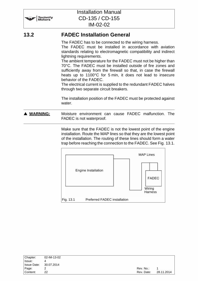
Installation ManualCD-135 / CD-155
IM-02-02
13.2 FADEC Installation GeneralThe FADEC has to be connected to the wiring harness. The FADEC must be installed in accordance with aviationstandards relating to electromagnetic compatibility and indirectlightning requirements. The ambient temperature for the FADEC must not be higher than70°C. The FADEC must be installed outside of fire zones andsufficiently away from the firewall so that, in case the firewallheats up to 1100°C for 5 min, it does not lead to insecurebehavior of the FADEC. The electrical current is supplied to the redundant FADEC halvesthrough two separate circuit breakers.
The installation position of the FADEC must be protected againstwater.
Make sure that the FADEC is not the lowest point of the engineinstallation. Route the MAP lines so that they are the lowest pointof the installation. The routing of these lines should form a watertrap before reaching the connection to the FADEC. See Fig. 13.1.
WARNING: Moisture environment can cause FADEC malfunction. TheFADEC is not waterproof.
Fig. 13.1 Preferred FADEC installation
Wiring Harness
MAP Lines
Chapter:Issue:Issue Date:Page:Content:
02-IM-13-02430.07.2014222
Rev. No.:Rev. Date:
128.11.2014

Installation ManualCD-135 / CD-155
IM-02-02
13.3 FADEC Electrical Power SupplyThe electrical system must be designed in such a way that apermanent supply of the FADEC is assured. Once there is aninterruption of the FADEC electrical power supply the FADEC willreboot and reinitialize. The FADEC reboot and reinitializationtime is less than 1.5 seconds. This will result in Total Loss ofPower events, for aircraft installations, in which the propellerautomatically goes into the feather position in case of loss ofelectrical power to the propeller control. In configurations such asthese, further requirements to the electrical system may benecessary.
Therefore the electrical system must meet the following specificrequirements in order to enable installation of the CD-135 andCD-155: A voltage supply failure in the electrical power supply of theaircraft must not result in any significant loss of performance.This means that the electrical power supply to the FADEC needsto remain intact in such cases. This requirement is part of the certification basis of the CD-135and CD-155 and must therefore be complied with for everyinstallation.A permanent sufficient electrical power supply is understood tobe a supply of electric power without interruptions, not below8V DC (12 / 24 V). Interruptions or voltage drops of electricalpower supply to a voltage below 8V DC (12 / 24 V) will result inFADEC reboot and reinitialization. The electric power supply hasto be compliant to the following:
Table 13.2 Electrical Power Requirements
Electrical Power RequirementsItem 12V DC nominal 24 DC nominalVoltage 9 to 16V DC 18 to 32V DC
Current 10 amps (max. 12 amps) 5 amps (max. 8 amps)
Transients
Not to exceed:30V DC for 0.1 sec.20V DC for 1.0 sec.
Not below:8V DC
Not to exceed:60V DC for 0.1 sec.40V DC for 1.0 sec.
Not below:8V DC
Rev. No.:Rev. Date:
Chapter:Issue:Issue Date:Page:Content:
02-IM-13-02430.07.2014322
128.11.2014

Installation ManualCD-135 / CD-155
IM-02-02
At least one FADEC half should have a voltage above 8V all thetime. If this can not be assured, the aircraft manufacturer mustshow that a loss of thrust for 1.5 sec caused by the FADEC resetis no hazard for the aircraft. The reliability of the aircraft suppliedelectrical power to the FADEC is dependent on the installationand must be determined by the aircraft manufacturer. Thereforea Functional Hazard Assessment and a Failure Mode and EffectAnalysis have to be prepared to identify conditions which mightcreate a hazard to the aircraft. These assessments must take intoaccount the possible interruption of the electrical power supply tothe FADEC. For determination of system reliability FAA ACguidance material to FAR 23.1309 should be followed. The inputto these analyses and their results should be coordinatedbetween aircraft and engine manufacturer.The reliability of the entire engine control system is at least 1event in 54245h which is equivalent to a failure rate of 1.8434 x10⁻⁵.
The minimum reliability of the entire FADEC electrical powersupply should assure that the probability of a total loss of thrustdue to a failure or an interruption of aircraft supplied electricalpower supply is compliant with the requirement of the aircraftinstallation.
13.4 Installation FADEC Pressure Sensor LinesThe FADEC must (additionally to the electrical installation) alsobe supplied with pressure connections for ambient staticpressure and MAP (manifold air pressure). When designing thepressure connections, the following has to be considered:1. All connections and pipes need to be protected against
being constricted or kinked.2. The MAP connections must be completely pressure
resistant to min. 5 bar absolute. Provisions must be madethat no condensed water or other fluids can ingress into theMAP connector.
3. On the ambient pressure connections, the probability ofmalfunctions due to the ingress of foreign substances oricing must be minimized. This can be done by e.g.connecting them to a suitable aircraft static port system orby connecting an appropriate filter upstream (such as a fuelfilter).
Chapter:Issue:Issue Date:Page:Content:
02-IM-13-02430.07.2014422
Rev. No.:Rev. Date:
128.11.2014
Installation ManualCD-135 / CD-155
IM-02-02
13.5 Layout of the Electrical SystemThe battery (or batteries) is the source of electrical power in theelectrical system of the aircraft. The alternator of the engine isdefined as the engine's own electrical power source. Thefollowing are the basic rules for the design of an appropriateelectrical system:1. The FADEC, alternator and battery must therefore be wired
in such a way that the FADEC power supply is still providedby the alternator in the event of failure of the aircraftelectrical power system in a quality as defined in Chapter13.3.
2. The electrical system of the engine and the electricalsystem of the aircraft shall be connected in a way thatfailures and short circuits in the electrical system of theaircraft do not lead to failure of the engine electrical system.This may be achieved by circuit breakers, fuses or bysupplying FADEC A and B by independent power suppliesor any other system that insures permanent power supplyto at least one FADEC halve. Aircraft installations where thepower supply to both FADEC halves drop below 8V for ashort time are acceptable if the resulting reset of the FADECand therefore loss of power for 1.5 sec is no hazard for theairplane.
3. It must always be possible to isolate the FADEC electricalsystem with the alternator both from the battery and fromthe rest of the electrical system of the aircraft via circuitbreaker or other means.
Please refer to the relevant manufacturer's instructions for thewiring of instruments (not included in the scope of supply).
13.6 WiringWhen implementing the wiring, it is especially important toensure that the wire cross-sections are large enough and that allcrimp connections are executed with care. A power supply to thecontrol system must be ensured at all times in the quality definedin Chapter 13.3.
To minimize voltage drops between the FADEC and otherelectrical equipment the ground connection supply wires need tobe low resistance.
WARNING: Improper wiring may result in reduced engine performance oreven misfiring of the engine.
Rev. No.:Rev. Date:
Chapter:Issue:Issue Date:Page:Content:
02-IM-13-02430.07.2014522
128.11.2014

Installation ManualCD-135 / CD-155
IM-02-02
SwitchesAll of the switches and buttons must be designed and installed inconformity with JAR 23.1367. The switches have to be labeled clearly related to their functionand installed in reach of the pilots.
Electrical power consumersOther electrical consumers not required for actual engineoperation must only be connected to the system via circuitbreakers or fuses to the main bus. These consumers must notconsume more than nominal 70A (14V system) or nominal 35A(28V system) together.
Compliance demonstration that transients of consumers of theelectrical aircraft system do not affected the FADEC electricalpower supply as specified in Chapter 13.3 at any time mustshown by the airframer.
Wire harness installationWhen installing the wiring harness, please ensure that it ismechanically fastened at several points to prevent chafing. Allwires must be routed and secured in a way which ensures thatthe connectors can be plugged in without tension.
All shielded wires must be attached via electrically conductingconnections to the engine block at the actuator and sensor endsof the wiring harness. They shall also not be extended orlengthened.
CAUTION: No tension allowed at all!
CAUTION: Do not remove connectors!
Chapter:Issue:Issue Date:Page:Content:
02-IM-13-02430.07.2014622
Rev. No.:Rev. Date:
128.11.2014

Installation ManualCD-135 / CD-155
IM-02-02
13.7 Connecting Points Wiring harness / FADEC / Battery RelayThe installation of the battery relay should occur with theconnections downwards to protect the connections from soilingor accidental contact. The grounds of the individual wires shouldbe brought together to produce a central ground connectionpoint. Dividing it up into several ground connection pointsreduces the system's immunity to interference while increasingthe probability of ground defects which may lead to malfunctionsand increased sensitivity to electromagnetic interference.
13.8 Technical Data of the Electrical Components and their Connections
13.8.1 Internal alternatorThe alternator is included in the scope of supply and is suppliedas a fixed installation on the engine.
13.8.2 Wiring of the alternatorThe alternator has a DC output of 12-14 V at 90A or 24-28V at60A in the 28V system. The connection of the main charging line to the alternator meetsAWG2 or better. This size guarantees a reliable supply to thesystem. The alternator shall be connected to the alternator regulator(ALTREG) and the failure warning lamp (AWL). The alternatorregulator shall be installed on the cockpit side of the firewall, withthe ventilation opening and the electrical connector facing down. The warning lamp illuminates if the alternator fails or if thealternator relay is switched off while a supply voltage from theelectrical system of the aircraft is present, and it normallyextinguishes when the engine is started. The operating voltage ofthe lamp is 12V or 24V, and the connections must not besubjected to loads in excess of 1.2W. The control lamp extinguishes at speeds greater than 1170 rpm(engine speed). It also illuminates if the voltage drops below 11.5V (14V system)or 23V (28V system).
CAUTION: No changes must be made to the configuration of the suppliedwiring harness as it is tested for EMC / immunity to interference.
Rev. No.:Rev. Date:
Chapter:Issue:Issue Date:Page:Content:
02-IM-13-02430.07.2014722
128.11.2014

Installation ManualCD-135 / CD-155
IM-02-02
The color of the control lamp depends on the classification of thesignificance of failure of the alternator system for the overallsystem and is defined in the relevant design regulations.The alternator requires an additional backup battery for theexcitation voltage (excitation battery) of at least 1.2 Ah at 12V or24V (depending on the system voltage). This battery must beintegrated into the system, and it must be possible to switch thisbattery off.The excitation battery must be installed in the cockpit and shouldbe a lead-gel model with a short service interval (e.g. one year)to guarantee proper operation without additional electronicmeasuring devices. One possible battery type is for example the lead-gelrechargeable battery "S312/1,2 S" from Exide Technologiessupplies this type under the order number NAS31201D2VW0SC.
The alternator of the CD-135 and CD-155 was tested as followsin compliance with EUROCAE ED14D / RTCA DO160D:
Conditions Section Description of tests conductedTemperature and Altitude 4.0 Alternator tested to Categories B2
Temperature Variation 5.0 Alternator tested to Category B
Humidity 6.0 Alternator tested to Category AOperational Shock and Crash Safety 7.0 Alternator identified as Category X. Operational Shocks
are tested during the 150 h endurance test of the engine
Vibration 8.0 Alternator identified as Category X. Vibrations are tested during the 150 h endurance test of the engine
Explosion 9.0 Alternator identified as Category X, no test performed
Waterproofness 10.0Alternator identified as Category X. Alternator was tested together with the engine during the JAR-E 430 water spray test
Fluids Susceptibility 11.0 Alternator identified as Category X, no test performedSand and Dust 12.0 Alternator tested to Category DFungus 13.0 Alternator identified as Category X, no test performedSalt Spray 14.0 Alternator tested to Category SMagnetic Effect 15.0 Alternator identified as Category X, no test performedPower Input 16.0 Alternator identified as Category X, no test performedVoltage Spike 17.0 Alternator identified as Category X, no test performedAudio Frequency Susceptibility 18.0 Alternator identified as Category X, no test performed
Induced Signal Susceptibility 19.0 Alternator identified as Category X, no test performed
Radio Frequency Susceptibility 20.0
Alternator tested to Section 20.4, Conducted Susceptibility, Category W and Category R Section 20.5, Radiated Susceptibility, Category R and Category U.
Radio Frequency Emission 21.0 Alternator tested to Category B
Lightning Induced Transient Susceptibility
22.0 Alternator identified as Category X, no test performed
Lightning Direct Effects 23.0 Alternator identified as Category X, no test performed
Icing 24.0 Alternator identified as Category X, no test performedElectrostatic Discharge 25.0 Alternator identified as Category X, no test performed
Chapter:Issue:Issue Date:Page:Content:
02-IM-13-02430.07.2014822
Rev. No.:Rev. Date:
128.11.2014
Installation ManualCD-135 / CD-155
IM-02-02
The alternator of the CD-135 and CD-155 was tested incompliance with TIP E.80DO160-02-02 Issue 4.In addition, the complete engine with alternator was subjected toan indirect lightning cable bundle test in accordance withEUROCAE ED14D / RTCA DO160D, Section 22,Waveform Set E, Level 5.
To compensate spikes a buffer (battery or capacitor) can beinstalled direct connected to the alternator.
13.8.3 Voltage warningA charge current failure warning system is not included in thescope of supply and needs to be installed additionally. JAR 23.1165 specifies that the pilot must receive a warning if thealternator no longer supplies charging current to the battery. Thiscould be done for example by monitoring the charging current(with an ammeter) or using a low voltage detection and warningdevice. If a warning is installed, JAR 23.1322 specifies that it must be red. The Technify Motors GmbH instrument panel AED-SR2incorporates a charge current monitoring system with integratedlow voltage detection and warning system.
13.8.4 Electrical starterThe electrical starter is included in the scope of supply and issupplied as a fixed installation on the engine. The starter is anelectromotive drive device which operates at 1.7 kW in 12V DCand with 2.5 kW in 24V DC systems and is the largest consumerin the entire electrical system of the engine system. It has to beassured that the installation meets the requirements of Chapter13.3, otherwise the engine will not start.The starter is triggered by a starter relay.
13.8.5 Starter relayThe starter relay is incorporated in the starter.
WARNING: The alternator characteristic depends on its installation. Thesuitability of the alternator installation has to be shown in theaircraft certification.
WARNING: The main current supply to the starter must be routed withspecial care. This connection cannot be protected with a fuse,so the routing must therefore ensure that there is no increasedrisk of fire in the event of a short circuit.
Rev. No.:Rev. Date:
Chapter:Issue:Issue Date:Page:Content:
02-IM-13-02430.07.2014922
128.11.2014

Installation ManualCD-135 / CD-155
IM-02-02
13.8.6 Starter switchThe starter switch actuate the starter. The starter switch mustswitch 5 A (minimum). When selecting and installing the starterswitch, compliance to JAR 23.1145 is required.
13.8.7 Glow relay and glow plug control unit (GPC) The glow relay is exclusively triggered by the FADEC, and theappropriate connections are provided with the engine wiringharness. The relay must be suitable for loads of 30 A. It is also importantto ensure that the crimped connections are of a high quality. Asupply line with the appropriate cross-section is connected to thebattery relay. The installation of the glow relay is almost entirely defined by thewiring harness on the engine side. The length of the supply linefrom the glow relay to the battery relay should be kept as short aspossible.
13.8.8 Glow displayA display lamp is provided to indicate when the glow plugpreheating system is active. The connection must not besubjected to loads in excess of 2W. This lamp must be designedto comply with JAR 23.1322.
13.8.9 Battery relayThe battery relay must be suitable for temporary loads in excessof 300 A and continuous loads of 100 A. It is actuated via thebattery switch.
Note: The installation should be performed in such a way that allconnections are protected against chafing, vibrating andcontamination with dirt.
Note: The locations of all relays should be chosen to ensure that theyare not subjected to excessive effects from heat or pollutants.
Chapter:Issue:Issue Date:Page:Content:
02-IM-13-02430.07.20141022
Rev. No.:Rev. Date:
128.11.2014

Installation ManualCD-135 / CD-155
IM-02-02
13.8.10 BatteryThe battery is not a part of the engine and belongs to theelectrical system of the aircraft ("aircraft supplied power"). Thebattery in the 14V system must meet the following performancedata requirements:Voltage: ................................................................................ 12 VCapacity: ...........................................................min. 35 Ah (C10)Current: .......................................................... temporary (5 min.)
minimum 200 Acontinuous (30 min.)
minimum 40 A
A possible choice of battery is the Gill Battery G35.
The battery in the 28V system must meet the followingperformance data requirements:Voltage: ................................................................................ 24 VCapacity: .............................................................min. 10 Ah (C1)Current: ........................................................... temporary (1 min)
min. 100 A
A possible choice of battery is the Gill Battery G243.
Another installation satisfying these minimum requirementswould also be acceptable, such as one with redundant batteries.
WARNING: The minimum capacity of the battery is sufficient for starterrequirements and to supply FADEC and typical essential loadsfor 120 minutes. The actual aircraft installation must be checked,if the capacity of the battery is sufficient to supply essential loadsfor 120 minutes.
WARNING: The minimum capacity of the battery is sufficient for starterrequirements and to supply FADEC and typical essential loadsfor 120 minutes. The actual aircraft installation must be checked,if the capacity of the battery is sufficient to supply essential loadsfor 120 minutes.
Rev. No.:Rev. Date:
Chapter:Issue:Issue Date:Page:Content:
02-IM-13-02430.07.20141122
128.11.2014
Installation ManualCD-135 / CD-155
IM-02-02
13.8.11 Engine MasterThe Engine Master switches both the power lines to the FADECand the excitation battery connection to the alternator.
13.8.12 Main switch / Main Bus switchThe divided Master switch controls the Alternator relay and MainBus relay. Compliance with JAR 23.1361 must be ensured wheninstalling the Master switch.
13.8.13 Additional ground power connectionIf additional external supply voltage connections are installed,they have to be equipped with reverse voltage protection incompliance with JAR 23.1351. The instructions of otherequipment manufacturers have to be taken into account.
13.8.14 CAN connectorThe CAN diagnostic connector is supplied with a terminatingconnector. This connector must be installed in a way whichprotects it against moisture and dirt.
Y-connections are not allowed for a CAN Bus. The terminatingconnector must be connected at the end of the bus behind theadditional CAN device.
13.8.15 FADEC warning lightsThese display lamps are used to warn of failure of the FADEC. JAR 23.1322 must be observed for the installation. Theconnected loads must not exceed 2W.
CAUTION: When selecting the installation location for the terminatingconnector, make sure that it is not possible to (even accidentally)disconnect it. If you connect something to the CAN-Bus, makesure you have a bus structure.
CAUTION: Choose the installation locations for these lamps so that theycan be easily seen by the pilot. The installation must comply withJAR 23.1322.
Chapter:Issue:Issue Date:Page:Content:
02-IM-13-02430.07.20141222
Rev. No.:Rev. Date:
128.11.2014
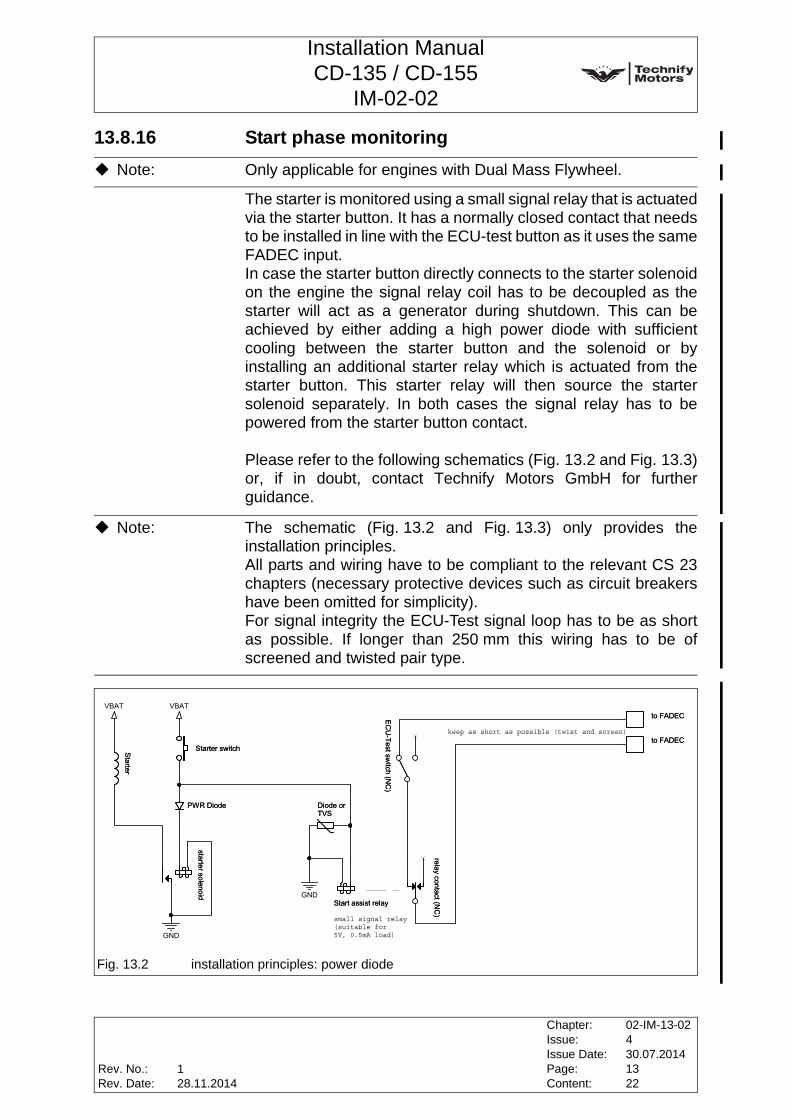
Installation ManualCD-135 / CD-155
IM-02-02
13.8.16 Start phase monitoring
The starter is monitored using a small signal relay that is actuatedvia the starter button. It has a normally closed contact that needsto be installed in line with the ECU-test button as it uses the sameFADEC input. In case the starter button directly connects to the starter solenoidon the engine the signal relay coil has to be decoupled as thestarter will act as a generator during shutdown. This can beachieved by either adding a high power diode with sufficientcooling between the starter button and the solenoid or byinstalling an additional starter relay which is actuated from thestarter button. This starter relay will then source the startersolenoid separately. In both cases the signal relay has to bepowered from the starter button contact.
Please refer to the following schematics (Fig. 13.2 and Fig. 13.3)or, if in doubt, contact Technify Motors GmbH for furtherguidance.
Note: Only applicable for engines with Dual Mass Flywheel.
Note: The schematic (Fig. 13.2 and Fig. 13.3) only provides theinstallation principles. All parts and wiring have to be compliant to the relevant CS 23chapters (necessary protective devices such as circuit breakershave been omitted for simplicity). For signal integrity the ECU-Test signal loop has to be as shortas possible. If longer than 250 mm this wiring has to be ofscreened and twisted pair type.
Fig. 13.2 installation principles: power diode
VBAT
GND
GND
VBAT
power diode
keep as short as possible (twist and screen)
small signal relay(suitable for5V, 0.5mA load)
Starter
Starter
to FADECto FADEC
Start assist relayStart assist relay
Starter switchStarter switchto FADECto FADEC
relay contact (NC
)relay contact (N
C)
PWR DiodePWR Diode
EC
U-Test sw
itch (NC
)E
CU
-Test switch (N
C)
Diode orTVSDiode orTVS
starter solenoidstarter solenoid
Rev. No.:Rev. Date:
Chapter:Issue:Issue Date:Page:Content:
02-IM-13-02430.07.20141322
128.11.2014
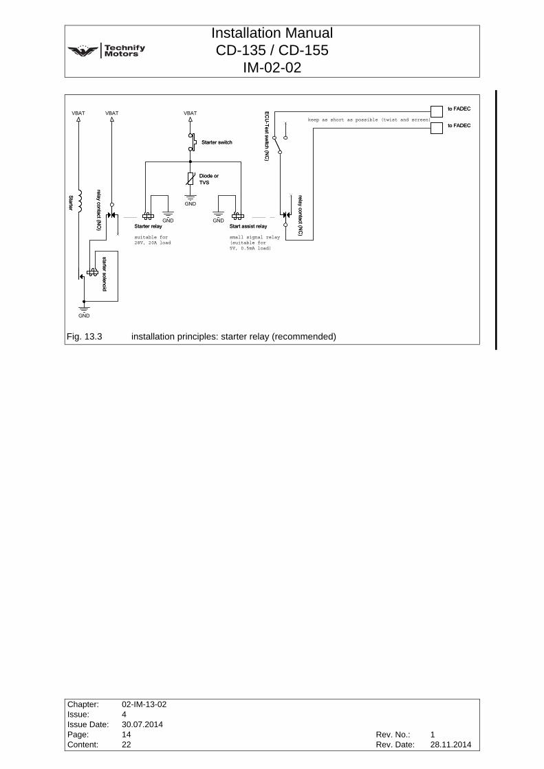
Installation ManualCD-135 / CD-155
IM-02-02
Fig. 13.3 installation principles: starter relay (recommended)
Wiring Harness
MAP Lines
VBAT
GND
GND
VBAT VBAT
GND
GND
Title
Size Document Number
Start monitoringTitle
Size Document Number
Start monitoringTitle
Size Document Number
Start monitoring
starter relay (r
Installation accordin(protective devices n
keep as short as possible (twist and screen)
small signal relay(suitable for5V, 0.5mA load)
suitable for28V, 20A load
to FADECto FADEC
Starter
Starter
EC
U-Test sw
itch (NC
)E
CU
-Test switch (N
C)
Starter switchStarter switch
relay contact (NO
)relay contact (N
O)
starter solenoidstarter solenoid
Start assist relayStart assist relay
relay contact (NC
)relay contact (N
C)
to FADECto FADEC
Diode orTVSDiode orTVS
Starter relayStarter relay
Chapter:Issue:Issue Date:Page:Content:
02-IM-13-02430.07.20141422
Rev. No.:Rev. Date:
128.11.2014

Installation ManualCD-135 / CD-155
IM-02-02
13.9 Instrument connections
For installations with the GARMIN 1000 and later versions, theCAN data flow is defined in the specification CANSPEC 02-01(Issue 5 or later issue).
13.9.1 CED-125 engine display instrumentThe CED-125 engine display instrument receives its data fromthe CAN bus and displays the following readings:
• Propeller speed
• Load
• Oil pressure
• Oil temperature
• Coolant temperature
• Gearbox temperature
The TAE-CED125 engine display instrument with the partnumber 02-7730-5501-(xx)-(xx) was tested as follows inaccordance with EUROCAE ED14D / RTCA DO160D:
Note: The compliance for certification of the required individualinstruments according to the applicable requirements like JAR orFAR has to be accomplished by the aircraft or airframemanufacturer.
Note: Technify Motors GmbH offers an appropriate instrument panel(CED-125) under the order number 02-7730-5501-(xx)-(xx)which can be used to monitor all of the engine parameters. Thisdisplay is certified in accordance with JTSO-C113 by theLuftfahrt-Bundesamt.
Conditions Section Description of tests conductedTemperature and Altitude 4.0 TAE-CED125 tested to Categories A2 and B2
Temperature Variation 5.0 TAE-CED125 tested to Category B
Humidity 6.0 TAE-CED125 tested to Category AOperational Shock and Crash Safety 7.0 TAE-CED125 tested to Category B
Vibration 8.0 TAE-CED125 tested to Category S, test curve M
Explosion 9.0 TAE-CED125 identified as Category X, no test performed
Waterproofness 10.0 TAE-CED125 identified as Category X, no test performed
Fluids Susceptibility 11.0 Alternator identified as Category X, no test performed
Sand and Dust 12.0 TAE-CED125 identified as Category X, no test performed
Fungus 13.0 TAE-CED125 identified as Category X, no test performed
Rev. No.:Rev. Date:
Chapter:Issue:Issue Date:Page:Content:
02-IM-13-02430.07.20141522
128.11.2014

Installation ManualCD-135 / CD-155
IM-02-02
Salt Spray 14.0 TAE-CED125 identified as Category X, no test performed
Magnetic Effect 15.0 TAE-CED125 tested to Category Z. The distance for a deflection of Dc is less than 0.3 m
Power Input 16.0 TAE-CED125 tested to Category BVoltage Spike 17.0 TAE-CED125 tested to Category AAudio Frequency Susceptibility 18.0 TAE-CED125 tested to Category B
Induced Signal Susceptibility 19.0 TAE-CED125 identified as Category X, no test
performedRadio Frequency Susceptibility 20.0 TAE-CED125 tested to Category V
Radio Frequency Emission 21.0 TAE-CED125 tested to Category B
Lightning Induced Transient Susceptibility
22.0 TAE-CED125 identified as Category X, no test performed
Lightning Direct Effects 23.0 TAE-CED125 identified as Category X, no test
performed
Icing 24.0 TAE-CED125 identified as Category X, no test performed
Electrostatic Discharge 25.0 TAE-CED125 tested to Category A
Conditions Section Description of tests conducted
Chapter:Issue:Issue Date:Page:Content:
02-IM-13-02430.07.20141622
Rev. No.:Rev. Date:
128.11.2014
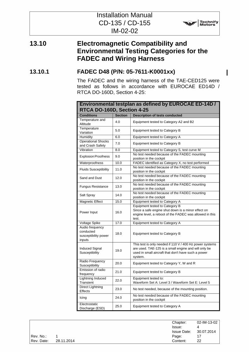
Installation ManualCD-135 / CD-155
IM-02-02
13.10 Electromagnetic Compatibility and Environmental Testing Categories for the FADEC and Wiring Harness
13.10.1 FADEC D48 (P/N: 05-7611-K0001xx)The FADEC and the wiring harness of the TAE-CED125 weretested as follows in accordance with EUROCAE ED14D /RTCA DO-160D, Section 4-25:
Environmental testplan as defined by EUROCAE ED-14D / RTCA DO-160D, Section 4-25Conditions Section Description of tests conductedTemperature and Altitude 4.0 Equipment tested to Category A2 and B2
Temperature Variation 5.0 Equipment tested to Category B
Humidity 6.0 Equipment tested to Category AOperational Shocks and Crash Safety 7.0 Equipment tested to Category B
Vibration 8.0 Equipment tested to Category S, test curve M
Explosion Proofness 9.0 No test needed because of the FADEC mounting position in the cockpit
Waterproofness 10.0 FADEC identified as Category X, no test performed
Fluids Susceptibility 11.0 No test needed because of the FADEC mounting position in the cockpit
Sand and Dust 12.0 No test needed because of the FADEC mounting position in the cockpit
Fungus Resistance 13.0 No test needed because of the FADEC mounting position in the cockpit
Salt Spray 14.0 No test needed because of the FADEC mounting position in the cockpit
Magnetic Effect 15.0 Equipment tested to Category A
Power Input 16.0
Equipment tested to Category BSince a safe engine shut down is a minor effect on engine level, a reboot of the FADEC was allowed in this test.
Voltage Spike 17.0 Equipment tested to Category AAudio frequency conducted susceptibility power inputs
18.0 Equipment tested to Category B
Induced Signal Susceptibility 19.0
This test is only needed if 110 V / 400 Hz power systems are used. TAE-125 is a small engine and will only be used in small aircraft that don't have such a power system.
Radio Frequency Susceptibility 20.0 Equipment tested to Category Y, W and R
Emission of radio frequency 21.0 Equipment tested to Category B
Lightning Induced Transient 22.0 Equipment tested to:
Waveform Set A: Level 3 / Waveform Set E: Level 5Direct Lightning Effects 23.0 No test needed, because of the mounting position.
Icing 24.0 No test needed because of the FADEC mounting position in the cockpit
Electrostatic Discharge (ESD) 25.0 Equipment tested to Category A
Rev. No.:Rev. Date:
Chapter:Issue:Issue Date:Page:Content:
02-IM-13-02430.07.20141722
128.11.2014

Installation ManualCD-135 / CD-155
IM-02-02
13.10.2 FADEC D4 (P/N: 05-7611-E0019xx)The FADEC and the wiring harness of the TAE-CED125 weretested as follows in accordance with EUROCAE ED14F /RTCA DO-160F, Section 4-26:
Environmental testplan as defined by EUROCAE ED-14F / RTCA DO-160F, Section 4-26Conditions Section Description of tests conductedTemperature and Altitude 4.0 Equipment tested to Category B2
Temperature Variation 5.0 Equipment tested to Category B
Humidity 6.0 Equipment tested to Category AOperational Shocks and Crash Safety 7.0 Equipment tested to Category B
Vibration 8.0 Equipment tested to Category S, test curve L/M
Explosion Proofness 9.0 No test needed because of the FADEC mounting position in the cockpit
Waterproofness 10.0 FADEC identified as Category X, no test performed
Fluids Susceptibility 11.0 No test needed because of the FADEC mounting position in the cockpit
Sand and Dust 12.0 No test needed because of the FADEC mounting position in the cockpit
Fungus Resistance 13.0 No test needed because of the FADEC mounting position in the cockpit
Salt Spray 14.0 No test needed because of the FADEC mounting position in the cockpit
Magnetic Effect 15.0 Equipment tested to Category APower Input 16.0 Equipment tested to Category B (XX)Voltage Spike 17.0 Equipment tested to Category AAudio frequency conducted susceptibility power inputs
18.0 Equipment tested to Category B
Induced Signal Susceptibility 19.0 Equipment tested to Category ZC
Radio Frequency Susceptibility 20.0 Equipment tested to Category Y and R
Emission of radio frequency 21.0 Equipment tested to Category B
Lightning Induced TransientSusceptibility
22.0
Equipment tested to:Waveform Set A: Level 3
Cable Bundle Tests (all screens removed, separate bundles)Multiple burst: W3: Level 3Single stroke: done as part of multiple strokeMultiple stroke: W4: 300V/75V; W3 1200V/750V (engine loom) 600V/300V (CAN and supply lines)
Direct Lightning Effects 23.0 No test needed, because of the mounting position.
Icing 24.0 No test needed because of the FADEC mounting position in the cockpit
Electrostatic Discharge (ESD) 25.0 Equipment tested to Category A
Fire Flammability 26.0 No test needed because of ECU mounting position in the cockpit / similarly protected area.
Chapter:Issue:Issue Date:Page:Content:
02-IM-13-02430.07.20141822
Rev. No.:Rev. Date:
128.11.2014

Installation ManualCD-135 / CD-155
IM-02-02
13.11 Lightning ProtectionThe FADEC of the CD-135 and CD-155 is protected against theeffects of indirect lightning strike. In order to protect the aircraftfrom the effects of a direct lightning strike at the propeller, it isnecessary to offer the lightning current a path of low impedancefrom the engine to the aircraft skin.
The following measures must be implemented or taken intoconsideration during installation:
• As the engine is mounted on vibration dampers made of rubber, all three bearings must be bridged with a grounding strap which should be as short as possible and have a sufficiently large cross-section and low impedance.
• To prevent the flow of larger currents through the wiring harness, a grounding strap which should be as short as possible should be routed from the engine to the firewall. This grounding strap must be tightly strapped to the wiring harness. All grounding straps of the engine control system are integral part of the engine wiring harness.
• Ground straps between the engine and its mount shall not be longer than 220 mm.
• The battery should be mounted directly on the firewall. If this is not possible, the battery lines should be routed in parallel, and the negative line of the battery should also be additionally grounded on the firewall.
• If the battery is not mounted directly at the firewall, it should also be checked whether the inputs of the FADEC should also be additionally protected with two varistors.
• Relays in the electrical system of the aircraft which are equipped with diodes for the suppression of over-voltages must be checked for their behavior under lightning strike. These diodes may short-circuit under a lightning strike, thus preventing the relay from functioning. Therefore, the diodes should be removed from all critical relays, or such critical relays should be equipped with a fuse which is connected in series.
Rev. No.:Rev. Date:
Chapter:Issue:Issue Date:Page:Content:
02-IM-13-02430.07.20141922
128.11.2014
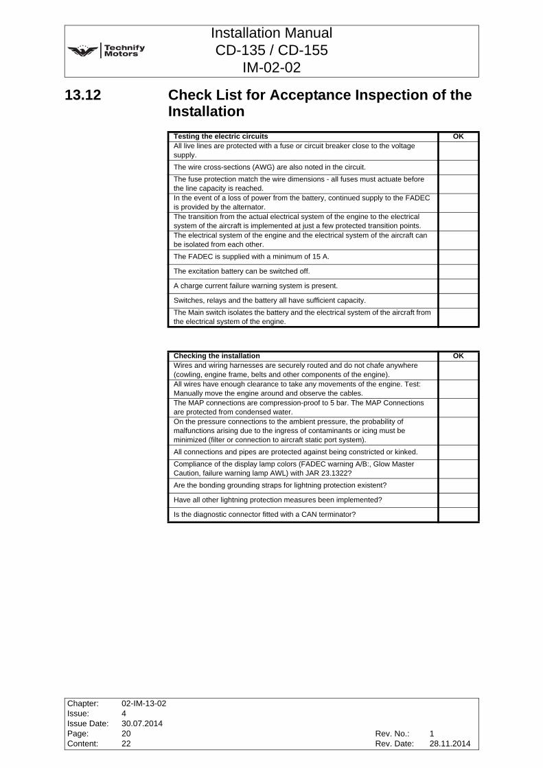
Installation ManualCD-135 / CD-155
IM-02-02
13.12 Check List for Acceptance Inspection of the Installation
Testing the electric circuits OKAll live lines are protected with a fuse or circuit breaker close to the voltage supply.The wire cross-sections (AWG) are also noted in the circuit.The fuse protection match the wire dimensions - all fuses must actuate before the line capacity is reached.In the event of a loss of power from the battery, continued supply to the FADEC is provided by the alternator.The transition from the actual electrical system of the engine to the electrical system of the aircraft is implemented at just a few protected transition points.The electrical system of the engine and the electrical system of the aircraft can be isolated from each other.The FADEC is supplied with a minimum of 15 A.
The excitation battery can be switched off.
A charge current failure warning system is present.
Switches, relays and the battery all have sufficient capacity.The Main switch isolates the battery and the electrical system of the aircraft from the electrical system of the engine.
Checking the installation OKWires and wiring harnesses are securely routed and do not chafe anywhere (cowling, engine frame, belts and other components of the engine).All wires have enough clearance to take any movements of the engine. Test: Manually move the engine around and observe the cables.The MAP connections are compression-proof to 5 bar. The MAP Connections are protected from condensed water.On the pressure connections to the ambient pressure, the probability of malfunctions arising due to the ingress of contaminants or icing must be minimized (filter or connection to aircraft static port system).All connections and pipes are protected against being constricted or kinked.Compliance of the display lamp colors (FADEC warning A/B:, Glow Master Caution, failure warning lamp AWL) with JAR 23.1322?Are the bonding grounding straps for lightning protection existent?
Have all other lightning protection measures been implemented?
Is the diagnostic connector fitted with a CAN terminator?
Chapter:Issue:Issue Date:Page:Content:
02-IM-13-02430.07.20142022
Rev. No.:Rev. Date:
128.11.2014
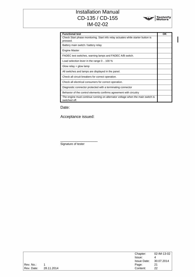
Installation ManualCD-135 / CD-155
IM-02-02
Date:
Acceptance issued:
_________________Signature of tester
Functional test OKCheck Start phase monitoring. Start info relay actuates while starter button is pressed.Battery main switch / battery relay
Engine Master
FADEC test switches, warning lamps and FADEC A/B switch.
Load selection lever in the range 0 .. 100 %
Glow relay + glow lamp
All switches and lamps are displayed in the panel.
Check all circuit breakers for correct operation.
Check all electrical consumers for correct operation.
Diagnostic connector protected with a terminating connector
Behavior of the control elements confirms agreement with circuitryThe engine must continue running on alternator voltage when the main switch is switched off.
Rev. No.:Rev. Date:
Chapter:Issue:Issue Date:Page:Content:
02-IM-13-02430.07.20142122
128.11.2014

Installation ManualCD-135 / CD-155
IM-02-02
This page intentionally left blank
Chapter:Issue:Issue Date:Page:Content:
02-IM-13-02430.07.20142222
Rev. No.:Rev. Date:
128.11.2014

Installation ManualCD-135 / CD-155
IM-02-02
14 Propeller Drive
14.1 General
14.2 Technical Data for the Propeller FlangeDirection of rotation of the propeller flange: ................ clockwise,
refer toChapter 3, Section 3.4, Page 2 of this Manual
Position: ................................................. in the coordinate centerPropeller shaft flange connection:..only use bolts recommended
by the propeller manufacturerHole circle: ........................................................................80 mmStraightway bore: .............................................6 bores, 11.4 mmGear reduction: ................................................................ i = 1.69
(3880 RPM engine = 2300 RPM prop)Max. torque on the propeller shaft: ................................. 473 Nm
Note: Applicability of the components from the aircraft manufacturershall be made sure in accordance with JAR 23, FAR 23 andCS 23.
Fig. 14.1 Propeller shaft flange [mm]
Rev. No.:Rev. Date:
Chapter:Issue:Issue Date:Page:Content:
02-IM-14-02430.07.2014110
230.01.2015

Installation ManualCD-135 / CD-155
IM-02-02
14.3 Propeller
14.3.1 Installation Information
• The propeller must be mounted on the propeller flange according to the regulations in the Installation Manual of the propeller manufacturer.
• Tightening torque of the stop nuts 7/16" UNF for the propellers MTV-6-A-(1*)/(2**)-(3***)-(4****): in accordance with MT-Manual
14.3.2 Propeller Limitations
Propeller diameter:Minimum diameter....................................................... not limitedMaximum diameter........................................................1900 mm
Moment of inertia:Minimum moment of inertia......................................... not limitedMaximum moment of inertia..........................................0,89kgm²
Propeller weight:Minimum propeller weight ........................................... not limitedMaximum propeller weight ................................................... 19kg
Hub extension, distance from gearbox flange to blade center:Minimum distance ....................................................... not limitedMaximum distance ..........................................................184 mm
Propeller flange:Propeller flange ................................................................ A-Type
(See 14.2 Technical Data for the Propeller Flange)
WARNING: The propeller must NOT be mounted directly onto thecrankshaft.
WARNING: The suitability of the engine for a particular propeller-aircraftcombination has to be proofed as part of the type certification ofthe aircraft.
Chapter:Issue:Issue Date:Page:Content:
02-IM-14-02430.07.2014210
Rev. No.:Rev. Date:
230.01.2015

Installation ManualCD-135 / CD-155
IM-02-02
Propeller control system:Propeller controller ..........................PC_CSU: 05-7212-K0304xx
with valve: 05-7212-E0028xx (28V)
or05-7212-E0014xx (14V)
may only be usedSoftware .....................................Standard certified and released
FADEC software may only be used.
Propeller oil pressure:Minimum oil pressure in propeller control system ................0 bar
Maximum oil pressure in propeller control system during operation(Gearboxes without Oil/Water Heat Exchanger) ................21 bar(Gearboxes with Oil/Water Heat Exchanger) .....................22 bar
Propeller need to resist pressures up to ............................25 bar
Note: See service bulletin for latest released software versions (contact Technify Motors GmbH for any questions).
Note: The actual oil pressure in the propeller control depend on theoperation conditions (delta between target and actual RPM,aircraft speed, propeller type). It is a close loop controlledsystem, controlled by the propeller control regulator.
Rev. No.:Rev. Date:
Chapter:Issue:Issue Date:Page:Content:
02-IM-14-02430.07.2014310
230.01.2015

Installation ManualCD-135 / CD-155
IM-02-02
WARNING: Only the following propellers are suitable for this engine:MTV-6-A-(1*)/(2**)-(3***)-(4****)
max. diameter of the propeller is limited to: ..................1900 mmthe moment of inertia may not exceed: ........................0,89 kgm²
Note: Decoding shown in the following table:
MTV-6-A-(1*)/(2**)-(3***)-(4****)(1*) Feather provision (Hub):
- blank = no feather position possible
- C - F = counterweights for pitch change forces to increase pitch and feather position possible
(2**) Position of pitch change pin:
- blank = pin position for pitch change forces to decrease pitch (Constant Speed)
- CF (Constant Speed & Feather) pin position to allow feather, pitch change forces to increase pitch
(3***) Propeller Diameter:- Propeller diameter from 175 cm to 190 cm
(4****) Identification of blade design:- 69- 80- 129
Example: MTV-6-A/187-129(1*) Feather provision (Hub):
- blank = no feather position possible(2**) Position of pitch change pin:
- blank = pin position for pitch change forces to decrease pitch (Constant Speed)
(3***) Propeller Diameter:- Propeller diameter 187 cm
(4****) Identification of blade design:- 129
Chapter:Issue:Issue Date:Page:Content:
02-IM-14-02430.07.2014410
Rev. No.:Rev. Date:
230.01.2015
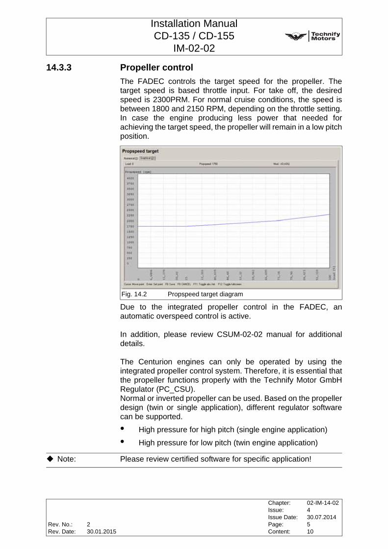
Installation ManualCD-135 / CD-155
IM-02-02
14.3.3 Propeller controlThe FADEC controls the target speed for the propeller. Thetarget speed is based throttle input. For take off, the desiredspeed is 2300PRM. For normal cruise conditions, the speed isbetween 1800 and 2150 RPM, depending on the throttle setting.In case the engine producing less power that needed forachieving the target speed, the propeller will remain in a low pitchposition.
Due to the integrated propeller control in the FADEC, anautomatic overspeed control is active.
In addition, please review CSUM-02-02 manual for additionaldetails.
The Centurion engines can only be operated by using theintegrated propeller control system. Therefore, it is essential thatthe propeller functions properly with the Technify Motor GmbHRegulator (PC_CSU).Normal or inverted propeller can be used. Based on the propellerdesign (twin or single application), different regulator softwarecan be supported.
• High pressure for high pitch (single engine application)
• High pressure for low pitch (twin engine application)
Fig. 14.2 Propspeed target diagram
2
Note: Please review certified software for specific application!
Rev. No.:Rev. Date:
Chapter:Issue:Issue Date:Page:Content:
02-IM-14-02430.07.2014510
230.01.2015

Installation ManualCD-135 / CD-155
IM-02-02
14.3.4 Basic testing requirementsThe propeller supplier shall show compliance in addition to allCS-P requirements.
14.3.5 Flight, operation verificationGround run:At maximum power at the ground (with no wind influence), thepropeller speed need to be between 2250 and 2300 RPM.
FADEC Test:The automatic FADEC is also verifying the propeller controlsystem since it is an integrated propeller control system.The FADEC and propeller pitch functional check must beconducted as described in Operation Manual OM-02-02. Inaddition to Operation Manual the propeller speed targets for eachstep in the functional check must be reached. After the test arecovery time of maximum 10 seconds. The FADEC andpropeller pitch functional check must be accomplishable withgearbox oil temperatures higher than 35°C.
Flight behavior stable throttle input:• Under all, constant flight conditions, the RPM need to
regulate within ±20RPM the target speed
• Larger oscillation or undamped behavior may not occur at any time
This need to be proven over the complete speed and altituderange with multiple power settings from idle to full power (40-50-60-70-80-90-100% throttle command) and up to maximumcertified altitude.
Chapter:Issue:Issue Date:Page:Content:
02-IM-14-02430.07.2014610
Rev. No.:Rev. Date:
230.01.2015
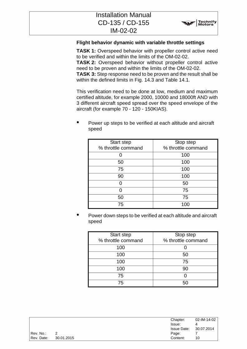
Installation ManualCD-135 / CD-155
IM-02-02
Flight behavior dynamic with variable throttle settingsTASK 1: Overspeed behavior with propeller control active needto be verified and within the limits of the OM-02-02.TASK 2: Overspeed behavior without propeller control activeneed to be proven and within the limits of the OM-02-02.TASK 3: Step response need to be proven and the result shall bewithin the defined limits in Fig. 14.3 and Table 14.1.
This verification need to be done at low, medium and maximumcertified altitude, for example 2000, 10000 and 18000ft AND with3 different aircraft speed spread over the speed envelope of theaircraft (for example 70 - 120 - 150KIAS).
• Power up steps to be verified at each altitude and aircraft speed
• Power down steps to be verified at each altitude and aircraft speed
Start step % throttle command
Stop step % throttle command
0 10050 10075 10090 1000 500 7550 7575 100
Start step % throttle command
Stop step % throttle command
100 0100 50100 75100 9075 075 50
Rev. No.:Rev. Date:
Chapter:Issue:Issue Date:Page:Content:
02-IM-14-02430.07.2014710
230.01.2015

Installation ManualCD-135 / CD-155
IM-02-02
Table 14.1 Definition overshoot behavior
Fig. 14.3 Definition overshoot behavior
2
Time [s]175 180 185 190 195 200 205
Prop
elle
r Spe
ed [1
/min
] Pro
pSpe
ed-T
arge
t [1/
min
]
1600
1700
1800
1900
2000
2100
2200
2300
2400
2500
2600
Propeller Speed PropSpeed-Target
A
B
C
D
E
Load
Lev
er S
ettin
g [%
]
0
50
100
Air Speed A B C D EVs-100KIAS 150RPM 2 sec 5 sec < 1 sec ±20RPM100-150KIAS 200RPM 2 sec 5 sec < 1 sec ±20RPM150KIAS- Vne 200RPM 2 sec 5 sec < 1 sec ±20RPM
Chapter:Issue:Issue Date:Page:Content:
02-IM-14-02430.07.2014810
Rev. No.:Rev. Date:
230.01.2015

Installation ManualCD-135 / CD-155
IM-02-02
High speed decent testPropeller Control behavior from Vs up to Vne with 100% Loadsetting, the RPM to regulate within ±20RPM of the target speed.This need to be verified at high and medium altitude within theenvelope of the certified aircraft. (Caution for potential flutter ofaircraft at high speed and high altitude)
Idle decent behavior• No oscillation may occur
• Propeller shall / will behave as a fix pitch propeller under those conditions
• Engine running condition need to be verified. No engine flame out may occur due to too low RPM.
• Minimum allowed RPM during this condition may not be less than 1000RPM.
Go-around behavior at different altitudesSame requirements as with specified Flight dynamic behavior.This need to be verified at low and medium altitudes (up to12000ft).
Rev. No.:Rev. Date:
Chapter:Issue:Issue Date:Page:Content:
02-IM-14-02430.07.2014910
230.01.2015

Installation ManualCD-135 / CD-155
IM-02-02
14.4 Constant Speed UnitOn the constant speed unit, must be set a primary pressure of
• 20 bar (290 psi)for Gearboxes without Oil/Water Heat Exchanger (refer to RM-02-02 Chapter 72-10.05)
• 21 bar (305 psi)for Gearboxes with Oil/Water Heat Exchanger (Laminova)(refer to RM-02-02 Chapter 72-10.16)
Fig. 14.4 Connecting the pressure gauge / setting the constant speedunit
a Pre-pressure regulatorb constant speed unit (CSU)c Screw plug of single stage pump
2
c
a b
Chapter:Issue:Issue Date:Page:Content:
02-IM-14-02430.07.20141010
Rev. No.:Rev. Date:
230.01.2015
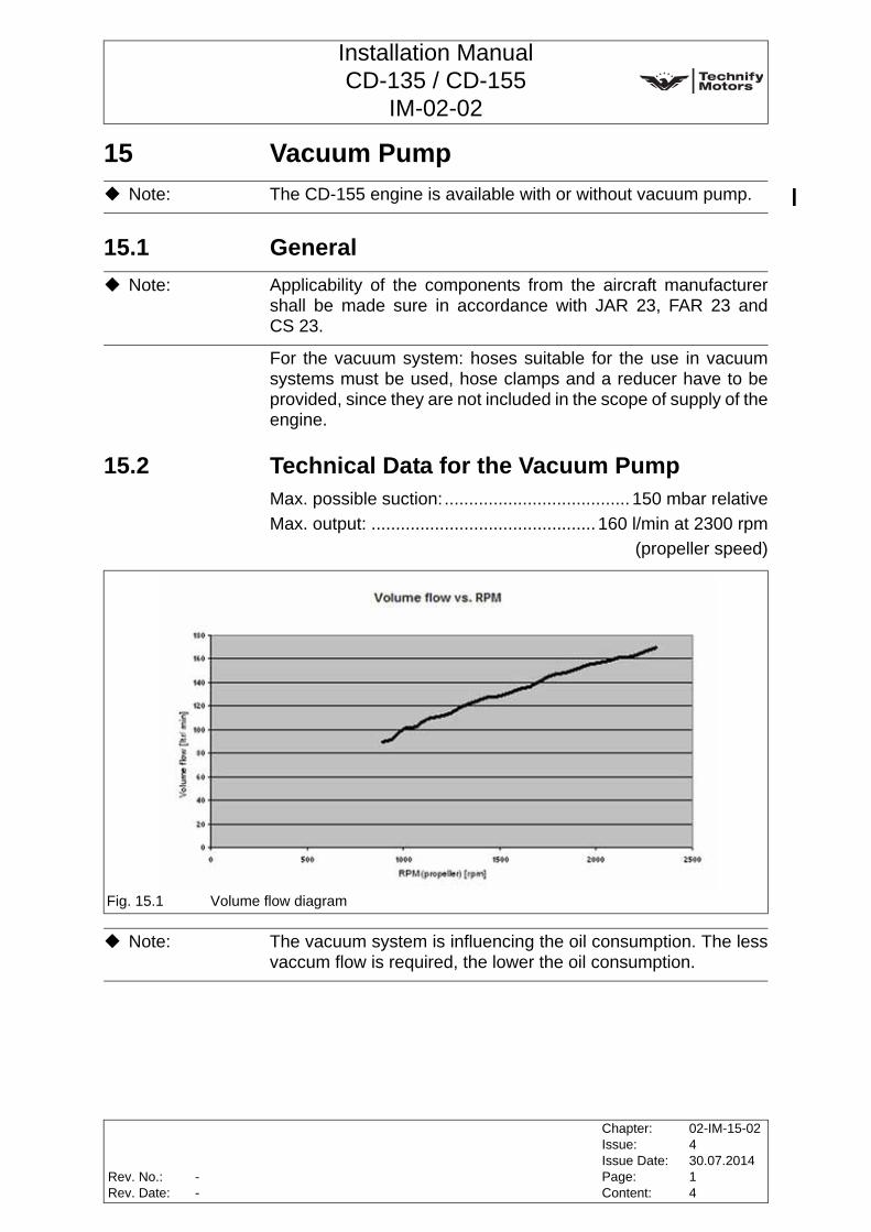
Installation ManualCD-135 / CD-155
IM-02-02
15 Vacuum Pump
15.1 General
For the vacuum system: hoses suitable for the use in vacuumsystems must be used, hose clamps and a reducer have to beprovided, since they are not included in the scope of supply of theengine.
15.2 Technical Data for the Vacuum PumpMax. possible suction:...................................... 150 mbar relativeMax. output: .............................................. 160 l/min at 2300 rpm
(propeller speed)
Note: The CD-155 engine is available with or without vacuum pump.
Note: Applicability of the components from the aircraft manufacturershall be made sure in accordance with JAR 23, FAR 23 andCS 23.
Fig. 15.1 Volume flow diagram
Note: The vacuum system is influencing the oil consumption. The lessvaccum flow is required, the lower the oil consumption.
Rev. No.:Rev. Date:
Chapter:Issue:Issue Date:Page:Content:
02-IM-15-02430.07.201414
--
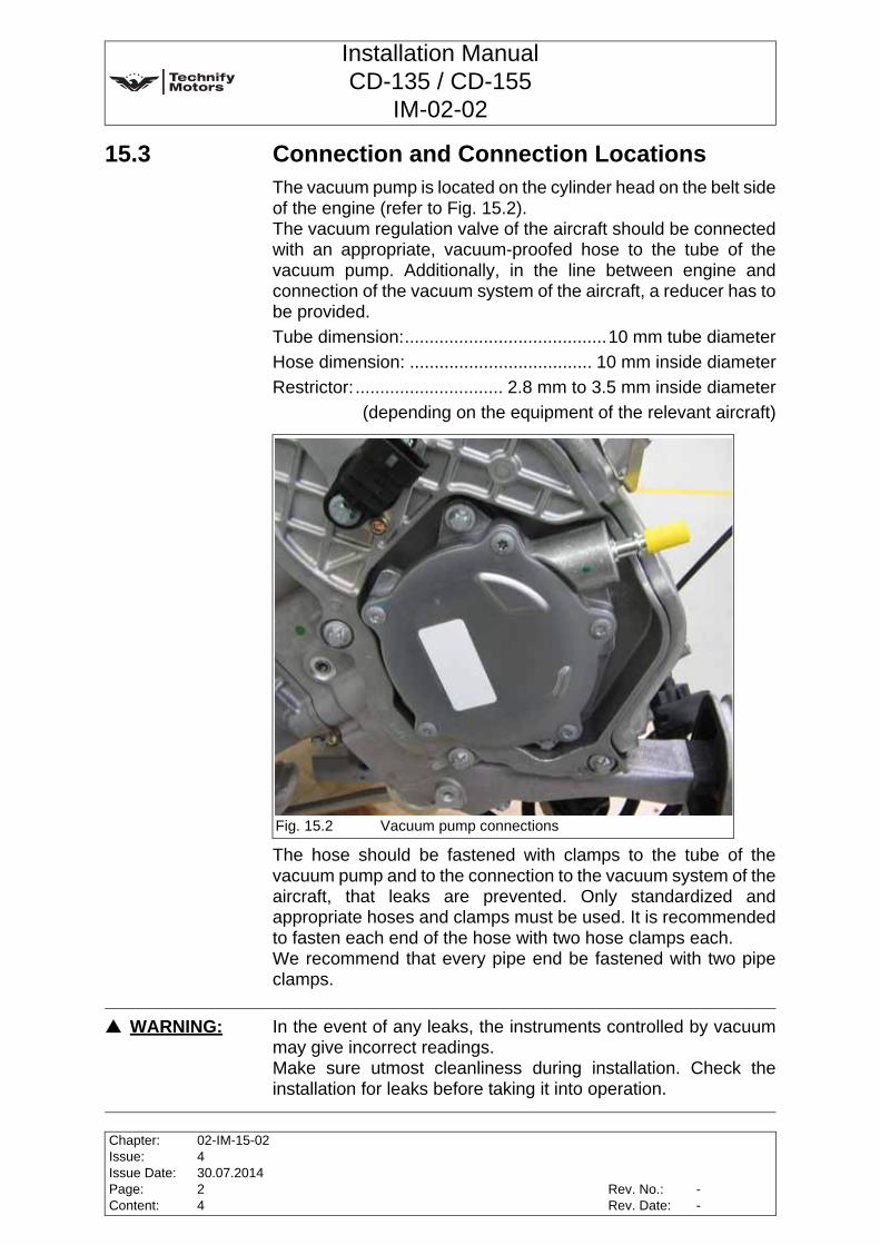
Installation ManualCD-135 / CD-155
IM-02-02
15.3 Connection and Connection LocationsThe vacuum pump is located on the cylinder head on the belt sideof the engine (refer to Fig. 15.2). The vacuum regulation valve of the aircraft should be connectedwith an appropriate, vacuum-proofed hose to the tube of thevacuum pump. Additionally, in the line between engine andconnection of the vacuum system of the aircraft, a reducer has tobe provided.Tube dimension:.........................................10 mm tube diameterHose dimension: ..................................... 10 mm inside diameterRestrictor: .............................. 2.8 mm to 3.5 mm inside diameter
(depending on the equipment of the relevant aircraft)
The hose should be fastened with clamps to the tube of thevacuum pump and to the connection to the vacuum system of theaircraft, that leaks are prevented. Only standardized andappropriate hoses and clamps must be used. It is recommendedto fasten each end of the hose with two hose clamps each. We recommend that every pipe end be fastened with two pipeclamps.
Fig. 15.2 Vacuum pump connections
WARNING: In the event of any leaks, the instruments controlled by vacuummay give incorrect readings. Make sure utmost cleanliness during installation. Check theinstallation for leaks before taking it into operation.
Chapter:Issue:Issue Date:Page:Content:
02-IM-15-02430.07.201424
Rev. No.:Rev. Date:
--

Installation ManualCD-135 / CD-155
IM-02-02
CAUTION: Remove the sealing cap on the tube drain of the vacuum pumpbefore fastening the hose.
CAUTION: Only standardized lines and connections must be used.
CAUTION: For the vacuum system, a commercially available filter must beused on the airframe side.
CAUTION: The vacuum pump is maintenance-free and only requires avisual inspection.
Rev. No.:Rev. Date:
Chapter:Issue:Issue Date:Page:Content:
02-IM-15-02430.07.201434
--

Installation ManualCD-135 / CD-155
IM-02-02
This page intentionally left blank
Chapter:Issue:Issue Date:Page:Content:
02-IM-15-02430.07.201444
Rev. No.:Rev. Date:
--