Embed Size (px)
Citation preview
PURCHASE SPECIFICATION
Doc. No:- REG2021-20200453
Part 03/05
Rudrapur GROUP : REG (RENEWABLE ENERGY GROUP) Rev no 00
Page 1 of 32 Signature and seal of Bidder
SUPPLY OF BALANCE OF SYSTEM (BOS), I&C OF SOLAR ROOF TOP SYSTEM ON THE ROOFS OF OFFICE AND RESIDENTIAL
BUILDINGS OF NTPC- MAUDA, NAGPUR, MAHARASHTRA– 530 kWp
SITE DETAILS & TECHNICAL SPECIFICATIONS FOR
530 kWp SOLAR SYSTEM
IMPORTANT NOTE
“BIDDER IS REQUESTED TO VISIT ALL THE SITES IN PERSON AND THEN SUBMIT THEIR BEST OFFER. ANY TYPE OF DENIAL
/OBJECTION WILL NOT BE ENTERTAINED AFTER FINALIZATION OF ORDER.”
PURCHASE SPECIFICATION
Doc. No:- REG2021-20200453
Part 03/05
Rudrapur GROUP : REG (RENEWABLE ENERGY GROUP) Rev no 00
Page 2 of 32 Signature and seal of Bidder
GENERAL SPECIFICATIONS

PURCHASE SPECIFICATION
Doc. No:- REG2021-20200453
Part 03/05
Rudrapur GROUP : REG (RENEWABLE ENERGY GROUP) Rev no 00
Page 3 of 32 Signature and seal of Bidder
1. BRIEF ABOUT THE PROJECT:
1.1 SCOPE OF WORK & TECHNICAL SPECIFICATIONS: The scope of work includes supply, Erection and commissioning of Roof top solar PV panels of capacity 530KW and associated auxiliaries on identified buildings of Mauda plant and township. Proposed building location is as mentioned in area of execution of work. However, before submitting the final bid, Bidder shall visit the site & assess the suitability of the available area. The system should be commissioned as a standalone system at NTPC Mauda Super Thermal Power Project. Scope also covers Operation and Maintenance (O & M) for Two (2) years for Solar Rooftop System at public buildings at NTPC Mauda. Bidder shall take necessary approvals and clearances from Govt/ statutory bodies wherever applicable in the scope of work and shall submit an affidavit after the completion of work. List of Identified rooftops indicating potential for proposed installation capacity:
Table: Roof Top Locations at NTPC Mauda:
Sl No
Location No of Buildings
Total Capacity (kWp)
Type of Roof
1 D2 Type Blocks 06 180 kWp RCC
2 Hospital Building 01 110 kWp RCC
3 School Building 01 100 kWp RCC
4 Fire station Building 01 65 kWp RCC
5 Training Center Building 01 75 kWp RCC
Total 530 kWp
Note: Building wise Modules layouts, SLD, MMS drawings, MQP of BoS, Earthing procedures, ICP of the project shall be as per NTPC approved documents and drawings attached with the tender.
PURCHASE SPECIFICATION
Doc. No:- REG2021-20200453
Part 03/05
Rudrapur GROUP : REG (RENEWABLE ENERGY GROUP) Rev no 00
Page 4 of 32 Signature and seal of Bidder
Part A: General Scope
1. Installation of items (In bidder’s scope) BHEL will supply PV modules and String inverters only. All other items required for completion of the system is in Bidder’s scope.
1.1. SPV Modules: ( Supply of Modules is in the scope of BHEL ) Bidder shall do the erection of the SPV module as per approved layout design of BHEL. Bidder shall implement the interconnection as per these drawings. Required number of nuts and bolts for the erection of Modules shall be supplied by bidders. These will be made of SS 304 material - NUTS, BOLTS AND PLAIN WASHERS. Installation activity shall include placing on base, bolting, clamping with Structure material, Ferrule Marking near String. Other fasteners like Clamp, brackets, M6 Screws shall also be supplied as required additionally. Series interconnection of SPV modules to form strings
Bidder shall interconnect the SPV modules as follows: a) Each module is fitted integrally with a junction box having positive and
negative polarity cables (4 Sqmm). b) Positive cable of one module shall be connected to the negative cable of
adjacent module. The cables have MC4 type of connectors to be supplied by contractor. One polarity cable has male type connector, while the other has female type connector.
c) This way, modules shall be connected in series. Each set of connections is called as a series string. Series formation may change as per approved layout and design.
Interconnection of SPV module strings to string inverters
a) Bidder shall connect each series string of 17-20 SPV modules to the DCDB/string inverter using 1Cx 4 cable, copper, XLPO, unarmored as per TUV 2pfg 1169/08.2007.
b) MC4 connectors shall have rating of 1000VDC (IEC), rated current of 30A, Type approved by TUV Rhineland for product safety. MC4 connector shall be supplied by Bidder.
c) Min. Two sets of tool kits (with box enclosure) shall be supplied by bidder. This shall include crimping plier MC4, open end spanner set MC4, stripping plier MC4, socket wrench insert to tighten, socket wrench insert to secure etc.
Required number of MC-4 Connectors each set having a pair of male and female parts, to join both the cables along with ferrules shall be supplied by Bidder. Bidder to check the module technical parameter along with Sr. No before final installation and fill the data in given format. Bidder shall mark the string and inverter number on both sides of the string.
PURCHASE SPECIFICATION
Doc. No:- REG2021-20200453
Part 03/05
Rudrapur GROUP : REG (RENEWABLE ENERGY GROUP) Rev no 00
Page 5 of 32 Signature and seal of Bidder
1.2. Installation of string inverters ( Supply of string inverters is in the scope of BHEL) Approximate weight of inverter 50-70 Kg.
a) Installation of string Inverter on Roof: On roof tops, the Inverter shall be mounted on MS stand. Minimum ground clearance shall be 500mm. In case of outdoor installation - Structure shall have canopy (as rain shade)
made of GI sheet of minimum 2mm thick. Canopy shall be supplied and installed by Bidder.
Earthing of inverter shall be done by 2.5/4 sqmm CU wire green color.
b) Installation of String Inverter on Wall: On wall, Inverter shall be mounted on mounting plate. Minimum wall clearance shall be 50mm. Minimum ground clearance shall be 500mm. All structure items including hardware shall be in bidder scope of supply. Earthing of inverter shall be done by 2.5/4 sqmm CU wire green color.
1.3. Installation of DC combiner boxes (DCDB)- (Supply of DC Combiner boxes- DCDB is in bidder’s
scope) – No. of DCDBs shall be decided by Bidder as per attached SLD
a) Installation of DCDB on Roof: On roof tops, DCDB shall be mounted on MS stand that shall be attached by
welding to the Roof top MMS. Minimum ground clearance shall be 500mm. In case of outdoor installation - Structure shall have canopy (as rain shade)
made of GI sheet of minimum 2mm thick. Canopy shall be supplied and installed by Bidder.
All galvanizing shall be minimum 80 microns and as per IS: 4759, IS: 2629, IS: 2633
Bidder shall submit GA of the mounting structure along with stability calculations (STAAD.pro etc.) for BHEL/CUSTOMER approval during detailed engineering.
All structure/pedestal items including hardware shall be in bidder scope of supply.
Earthing of DCDB shall be done by 2.5/4 sqmm CU wire green color.
b) Installation of DCDB on Wall: On wall, Inverter shall be mounted on mounting plate. Minimum wall clearance shall be 50mm. Minimum ground clearance shall be 500mm. All galvanizing shall be minimum 80 microns and as per IS: 4759, IS: 2629, IS:
2633
PURCHASE SPECIFICATION
Doc. No:- REG2021-20200453
Part 03/05
Rudrapur GROUP : REG (RENEWABLE ENERGY GROUP) Rev no 00
Page 6 of 32 Signature and seal of Bidder
All structure items including hardware shall be in bidder scope of supply. Earthing of DCDB shall be done by 2.5/4 sqmm CU wire green color.
1.4. Installation of AC junction/combiner boxes (ACDB/ACCB)- (Supply of AC Combiner
boxes/ACCB is in bidder’s scope) – No. of ACDB/ACCB shall be decided by Bidder as per attached SLD
a) Installation of ACCB/ACDB on Roof: Installation scope same as per 1.3 (a)
b) Installation of ACCB/ACDB on Wall: Installation scope same as per 1.3 (b)
Note: Preferred location for the installation of Inverters, ACDB, ACCB and DCDB are on the roof.
Location shall be finalized with BHEL/NTPC during installation of the project.
2. Civil Pedestal: ( As per attached MMS and pedestal drawing) – In bidder’s scope
Basic specification calls for Cement Concrete will be as per drawing. Cement shall be good ISI Portland cement of reputed make. Cement bags shall bear ISI certification mark and date of manufacture. The sand shall be of river sand, clean & free from organic impurities. C.C. concrete shall be mixed well in watertight platform in proportion as specified all ingredients in required proportion shall be mixed, first dry & than required quantity of water shall be added. Mixing shall be turned over twice or thrice, so that surface of the coarse aggregate coated with cement & concrete shall be used within half an hour of mixing. Any quantity remaining unused after an hour of mixing will not be allowed to use. The casted pedestals shall be cured minimum for ten days after completion of work. It shall keep well-watered & shall be protected from direct heat of sunlight by means of wet gunny bags. Cement shall be procured by Bidder conforming to BIS: 8112 and / or BIS: 1489 Specification latest edition or higher Grade. The cement shall be procured directly from the reputed manufacturers/ stockiest as per approved list of BHEL/Customer. Relevant vouchers and test certificates will be produced as and when required. The cement shall be stored by the Bidder in such suitable covered and lockable stores, well protected from climate and atmospheric effects. The cement go-down shall be constructed by the Bidder as per the drawing in CPWD specifications at his own cost. The cement will remain under double lock, one from NBCC and other from Bidder. The cement in bags shall be stored in go-downs in easy countable position. Cement bags shall be used on first in first out basis. Cement stored for beyond 90 days will be required to be tested at Bidders cost, before use in works. Concrete shall consist of cement, sand & graded stone in required proportion. Coarse aggregate for all concrete shall be graded crushed hard granite, trap or basalt stone and shall conform to the requirements. All materials shall be carefully & accurately measured in measuring box. Cement shall either be weighed or used in full bags. The required quantity of water shall be added by measuring in water cans. Concrete shall be mixed by mixer machine. Before any concrete is placed in position, all loose pieces of Timber, Stones, saw dust etc. shall be removed from the work. No concrete mixed 30 minutes’ prior of placing in form shall be accepted. Proper water cement ratio shall be observed.
PURCHASE SPECIFICATION
Doc. No:- REG2021-20200453
Part 03/05
Rudrapur GROUP : REG (RENEWABLE ENERGY GROUP) Rev no 00
Page 7 of 32 Signature and seal of Bidder
Mechanical mixing method shall be adopted for mixing of concrete. The mechanical needle vibrator or other approved methods shall be adopted for compaction of the mix. The concrete consolidation shall be through & no honeycomb work (rough, pitted surface or voids in concrete) shall be allowed. All the formwork shall be provided by the Bidder at his cost & shall be thoroughly wetted before the concrete is placed in position. Formwork shall be of approved quality. Where timber is used, the face in contact with concrete shall be plain & made smooth. All the joints in formwork shall be perfectly close to prevent the loss of cement slurry from concrete. After the form works are complete, the Bidder shall get it checked for strength, suitability & levels. For this advance intimation shall be given for inspection. Sufficient number of framework/shuttering shall be maintained by the contractor at site to match the pace of the work required at site. Estimated number of shuttering is as specified below: For capacity up to 100KW: 150 Nos. J-Bolts –Supply & fixing: The anchor bolts (J bolt) shall be sunk into the wet concrete by hand immediately after the concrete slab is poured. The anchor shall be standing straight and projecting, as the concrete hardens. 4 Nos. of J-bolt of straight length shall be used general of 200mm in addition to bent portion at unthreaded end as per standard and may change as per MMS design. These bolts are threaded at the top, for about two inches, and the rest of the bolt is smooth. Diameter of J bolt shall be 10mm and TWO nos. nuts each and suitable washers shall be supplied with each bolt. Arrangement shall be as per Drawing. It is essential that a template or a plastic sleeve is used to hold the bolts in place until the concrete sets up enough to support the weight of the bolt. Using a template will help keep the bolts straight, plumb and the correct distance from each other. Note: J-bolt shall be made of Galvanized steel and Nuts and washer shall be made of SS304.
SAMPLING, INSPECTION & TESTING Sampling and testing of concrete shall be carried out by drawing random sample during various stages of inspection. Guiding standard shall be IS: 516. Cube Test on selected sample after 7 days curing & 28 days curing shall be conducted for compression strength. Sampling plan as below:
Concrete in m3/day work No of samples
01-05 1
06-15 2
16-30 3
31-50 4
51 and above additional 4 plus one sample for additional 50 cum or part thereof.
PURCHASE SPECIFICATION
Doc. No:- REG2021-20200453
Part 03/05
Rudrapur GROUP : REG (RENEWABLE ENERGY GROUP) Rev no 00
Page 8 of 32 Signature and seal of Bidder
Cube test report (in above time intervals) shall be submitted to this office along with final documents.
Pull Out Test Pull out test of casted pedestals on roof shall be arranged by the contractor free of cost. Necessary arrangement to show that the pedestal is able to withstand the toppling load due to its dead weight and application of Nitto Bond. BHEL will specify the testing criteria based on roof condition and local site conditions and based on its own design of civil pedestals. The selected locations where pull out test shall be conducted shall be based on decision taken by BHEL site engineer and based on any specific customer requirement. Note: If the dead weight/pedestal weight is equivalent or more than to the reaction weight as per STAAD calculation. Pull out test is not required. If adhesive material is being used between roof surface and PCC to counter the reaction weight, then this test shall be conducted by bidder.
Lifting Cost of Lifting of pedestals or raw material of pedestals up to the roof level is included in the contractor’s scope. For buildings of height up to 4th floor and for Tin Sheds of height up to 5 Mtrs. – no additional charges shall be payable for lifting. Preparation of Roof Marking on the roof for the placement of pedestal shall be done by the bidder as per the approved layout. Pedestal shall be placed after placement of the NITO BOND on the roof. For particular type of surfaces like waterproofed roof etc. – NITO BOND may not be required. In such cases – bidder will give prior intimation in writing to BHEL that NITO BOND is NOT being applied by them. Unless such intimation is given – the bidder will be presumed to have used NITO BOND in all cases and this will be part of site inspection by BHEL team. Marked surface to be prepared cleaning the roof by wire brush after that NITO BOND shall be applied on prepared roof. Supply of NITOBOND (If applicable) is in scope of Bidder.
3. Data logger cum monitoring system- (Supply and Installation- In bidder’s scope)
Bidder has to aggregate Data with data storage feature from each Inverter to a Single PC in Control Room. However, irradiance / temperature sensor set can be provided at one of the rooftops. The plant monitoring shall have following: • Measurement of Solar PV parameters at PCU / String Inverter level: PCU / String Inverter shall have provision of measuring and displaying actual value of AC & DC Voltage, AC & DC Current, and AC Power & Energy Generated by the Solar PV system. These PCU / String Inverter parameters shall have provision of data logging through Mod Bus (RS-485) protocol.

PURCHASE SPECIFICATION
Doc. No:- REG2021-20200453
Part 03/05
Rudrapur GROUP : REG (RENEWABLE ENERGY GROUP) Rev no 00
Page 9 of 32 Signature and seal of Bidder
• Solar Irradiance • Temperature: PV Cell temperature shall be provided at one of the modules at shade free location The above data has to be made available at separate terminal by integrating in the LAN network of the package. Bidder can utilize the available mode of data transmission. Any hardware required shall be included in the scope of the bidder.
Web based Remote Monitoring system must be compatible with data logger. The system shall be provided with required accessories and if required SIM card for wireless communication inside the premises. The rental and other costs of the SIM cards, IP address, Server charge (storage, access charge and other charges if any), and Rental charge of data communication for remote monitoring system for a period of two (02) years shall be in Bidder’s scope. Items required during Installation like control cable, hardware, lugs etc shall be arranged by Bidder.
4. Cable Laying (Supply of AC & DC cable in scope of Bidder)
Cable laying is in scope of bidder. Laying details as follows:
All accessories for cable laying, including clamps, hooks, ties, double compression cable
glands, cable lugs, SS304 bolts/ nuts/ plain and spring washers, anchoring arrangement
shall be in bidder scope of supply. Cutting the wall/surface and making good the same as
required is also included in the scope of the contractor. The Cable lengths supplied to site
will NOT be in cut to size condition. Contractor has to arrange for cutting of the cables and
jointing by using suitable cable jointing kits. All arrangement, tools & tackles in this regard
will be in Contractor’s scope.
Generally, jointing of cables in the run between two ends is not allowed. Hence, utmost
care has to be taken while cutting required length of cables. The joints, as required
otherwise due to any particular reason - shall be made only after getting prior consent
from BHEL.
Bidder/bidder will submit scheme for cable laying within 15 days of site mobilization. This
scheme will include following details:
(A) Approximate length of various sizes of cables based on routing agreed with customer/user during joint assessment at site. (Cable sizes shall be based on BHEL’s Electrical Single Line Diagram).
(B) Approximate requirement of laying through Conduits, Treys, Excavation etc. (C) Contractor to purchase the quantity of conduits, treys etc. after getting written
acceptance from BHEL.
Method of measurement of length of cable laying
PURCHASE SPECIFICATION
Doc. No:- REG2021-20200453
Part 03/05
Rudrapur GROUP : REG (RENEWABLE ENERGY GROUP) Rev no 00
Page 10 of 32 Signature and seal of Bidder
For the laying of 4 sq mm. DC cable (1 positive + 1 negative connection between different Modules) for formation of string – no additional charges shall be payable. This is covered in Module installation rate. After the point where cables from different routes are bundled together – these will be routed through cable treys. For routing of cable in Bundles up to 5 parallel lengths on Treys/conduits – no additional charges shall be payable on account of laying of cable. Rates of conduits/treys have been considered elsewhere.
For laying of DC cables in bundles of 6 parallel or more – rates as applicable for maximum sizes of different slots shall be applied. For example – if 6 cables of 4 Sqmm are grouped together for routing up to DCDB/AJB/Inverter – the applicable rates for 6x4=24 Sqmm (up to 35 sq mm) shall be followed. The cables shall be routed in such a way that the length of cables used is minimum and at the same time any specific requirement by customer/user is also complied with. The cables shall be grouped together to the maximum extent possible, while laying on treys/conduits. In case, BHEL observes during inspection that cable length has been taken on a higher side due to no particular such requirement and other better alternatives for cable routing are available – then BHEL will be free to ask for re-routing of the cable by the contractor without any additional charge. Length of Excavation, Trays and Conduits shall be calculated in measured length basis. These will be counted as one length only, for all cases in which clubbing of cables shall be done.
4.1. Routing of 1Cx4 cable below the SPV modules a) 1Cx4 cables connecting the SPV module strings to DCDB/inverters shall be
suitably routed below the SPV modules and along the horizontal purlin member of MMS structure. Also, the cables shall be fastened to the purlin using UV resistant cable ties that shall be in bidder scope of supply.
b) Spacing between two adjacent cable ties shall be so chosen as to ensure that there is no loose hanging of cables.
c) Cable ties, nylon polyamide 6.6 UV stabilized black, UL94 flammability rating V2, operating temperature up to 85 deg C, shall be used to arrest any possibility of movement or sagging. Width of the cable ties shall be minimum 4.5 mm. Length shall be so chosen as to ensure that the bunched cables are held firmly to the MMS structure. During detailed engineering, BHEL/CUSTOMER approval shall be obtained for the selected brand and sizes of cable tie.
4.2. Routing of 1Cx4 cable in GI cable trays
Where 1Cx4 cables run between two adjacent rows of structure and also where the cables run on the roof-floor up to DCDB/string inverters, routing shall be on GI cable trays W x H x T = 100x50x 2 mm, perforated type, with GI cover of
PURCHASE SPECIFICATION
Doc. No:- REG2021-20200453
Part 03/05
Rudrapur GROUP : REG (RENEWABLE ENERGY GROUP) Rev no 00
Page 11 of 32 Signature and seal of Bidder
minimum 2mm thick, coupler plates, GI hardware as per relevant IS standard. Suitable flexible PVC conduit shall be used wherever required for covering cable at entry into GI cable tray.
4.3. Termination of 1Cx4 (DC side), 3.5/4C AC cables at string inverters & ACCB/ACDB boxes
a) 1Cx4 cables of positive and negative polarities originating from SPV module strings shall be terminated at the DC input side of string inverters using MC4 connectors that are in bidder scope of supply for both ends.
b) For AC side connection at string inverters and ACCB/ACDB boxes, cable as per SLD, 1.1kV, Copper, XLPE, armored as per IS: 7098 part-1, together with nickel plated brass double compression cable glands, cable lugs, SS304 bolts/ nuts/ plain and spring washers shall be in bidder scope of supply. Termination shall be carried out using appropriate tools and torque setting as per BHEL/CUSTOMER approval.
4.4. Ferruling for 1Cx4 cable a) For 1Cx4 DC solar array cable, bidder shall provide UV resistant ferrules printed
with source/destination identification of cable connection. Printing details shall be submitted for BHEL/CUSTOMER approval during detailed engineering. Printing shall be of appropriate size to ensure readability.
b) Ferrules shall be provided on both the termination ends: module end, inverter end.
c) Supply of ferrule shall be in bidder scope. Make shall be reputed brand. Approval for make/ type/ color/ dimension etc. shall be obtained from BHEL/CUSTOMER prior to procurement.
4.5. Underground cable trenches and laying of cables from buildings to building if required. Routing of cables from buildings to buildings is not envisaged. However, if required due to specific conditions, such power, control, communication cables routed from one building to another building through underground cable trench (direct burying) as per IS: 1255. Typical trench details/dimensions are below only for tender purpose. During detailed engineering, cable trench layouts and cross section drawings as per IS: 1255 shall be submitted for BHEL/CUSTOMER approval.
i. Total trench depth = 750 mm minimum ii. Trench width = As per number of cables/ DWC pipes
iii. Trench shall have layers one over the other as below (from bottom to top):
a) Bottom layer shall be sand of IS: 383 with 75mm minimum thick. b) 3C power cables shall be laid over the sand layer. c) Another layer of sand of 75 mm minimum thick. d) Single layer of brick as protective cover e) Layer of sand of IS:383 with 75mm minimum thick f) All communication cables shall be laid within DWC pipe
PURCHASE SPECIFICATION
Doc. No:- REG2021-20200453
Part 03/05
Rudrapur GROUP : REG (RENEWABLE ENERGY GROUP) Rev no 00
Page 12 of 32 Signature and seal of Bidder
g) Layer of sand of IS:383 with 75mm minimum thick h) Single layer of brick as protective cover i) Trench shall, then, be filled with refill soil and compacted
Communication cables shall be routed through DWC pipe. Communication cables and DWC pipe shall be in bidder scope of supply. Bidder shall submit GTP/ make/ part number of the DWC pipe, accessories and tools for BHEL/CUSTOMER approval during detailed engineering. Bending radii for cables shall be as per IS: 1255. At pathway/road/drain/trench crossings, cables shall be routed through GI pipe of appropriate size that shall be in bidder scope of supply and technical details / brand etc shall be submitted for BHEL/CUSTOMER approval. It shall be ensured that a maximum of 60% of inner space of GI pipe shall be occupied by cables. Bidder shall take utmost care in laying the cables in order to prevent damages on outer sheath and inner insulation. In case cables found to be damaged/ cut after the laying in trenches, bidder shall remove the damaged portion and join the cut pieces using appropriate cable jointing kits that shall be in bidder scope of supply.
4.6. Laying and termination of RS485 cables Bidder shall supply and install RS485 cable, copper, 2Px0.5, twisted pair, screened, armoured in daisy chain loops (a) from data loggers to string inverters and (b) from MFM meters of LT Panels to data loggers, (c) from weather monitoring system to data loggers. All cable accessories such as glands, lugs, ties, ferrules, tags, trays etc. shall be in bidder scope of supply.
4.7. Identification marking of cables using cable tags
Cable tags shall be provided at both ends of the cables: at SPV modules, string Inverters, data loggers, ACCB boxes, LTPDB panels and so on.
Cable tag shall be of rectangular shape.
Cable tag shall be of 2mm thick aluminum with number punched (embossed) on it and securely attached to the cable by not less than two turns of 20 SWG GI wire conforming to IS:280.
Reference shall be made to “Cable installation methodology” of this specification. Bidder shall submit the technical details of cable tags, ID numbering scheme for BHEL/ CUSTOMER approval during detailed engineering.
4.8. Cable route markers Cable route markers and joint markers for underground cables shall be provided along the route of the cables as per section “Cable installation methodology” of this specification.
5. Supply and installation of Conduits (In Bidder’s scope)
Contractor shall supply along with all accessories for laying of cable through it and install
Double Wall Corrugated (DWC) HDPE pipe, ISI mark IIS 1930 part 2 & latest IS 16205-
part-24) pipes along with accessories in surface/recess including cutting the wall and
making good the same in case of recessed conduit as required. Conduits pipes shall be lay
as per the approved drawing/make list/ Instruction provided by BHEL/Customer.
Method of measurement shall be as detailed against Sl. No. 5 above. The Scheme for

PURCHASE SPECIFICATION
Doc. No:- REG2021-20200453
Part 03/05
Rudrapur GROUP : REG (RENEWABLE ENERGY GROUP) Rev no 00
Page 13 of 32 Signature and seal of Bidder
laying of cable treys, conduits shall be submitted by contractor for approval of BHEL. After
getting clearance from BHEL only – contractor shall make procurement of required
quantity of cable treys, conduits etc.
6. Supply and installation of Cable trey (In bidder’s scope)
Contractor shall supply along with all accessories for laying of cable through cable trey and install suitable size of Cable trey along with accessories in surface/recess including cutting the wall and making good the same in case of recessed trey as required. Cable Trey shall be lay as per the approved drawing/make list/ Instruction provided by BHEL/Customer.
Cable trays shall be ladder/perforated type as specified completely with matching fittings (like brackets, elbows, bends, reducers, tees, crosses etc.), hardware and accessories as required. Cable tray should be ladder type for power and control cables and perforated for instrumentation cables.
Cable trays, fittings and accessories shall be fabricated out of rolled mild steel sheets free from flaws such as laminations, rolling marks, pitting etc. These (including hardware) shall be hot dip galvanized as per relevant IS.
Thickness of mild steel sheets used for fabrication of cable trays and fittings shall be 2mm thickness. Thickness of side coupler plates shall be 2mm.
Suitable GI support system for cable trays has to be provided which shall be able to withstand weight of cable trays, cables and factor of safety of at least 1.5 shall be considered while designing the system
All couplers, fixing screws, 45/90 degree bends, intersections, dividers are included in
scope.
For cable routing through exposed surfaces to rain – Cable Trey lid and Standoff
brackets (for suitably raising the trey above surface for rain protection by minimum 50
mm) shall be used. Also, for important indoor locations Cable Trey lid shall be used for
best aesthetic purpose.
Method of measurement shall be as detailed against Sl. No. 5 above. The Scheme for
laying of cable treys, conduits shall be submitted by contractor for approval of BHEL. After
getting clearance from BHEL only – contractor shall make procurement of required
quantity, particular size of cable treys.
Bidder has to supply and install cable trey (with cover) with accessories.
Cable Trey shall be lay as per the approved drawing/Instruction provided by
BHEL/Customer.
7. Supply and installation of Earthing strip with all accessories (In bidder’s
scope) Bidder has to supply and install Earthing strip of Galvanized steel material of following
size:
a) 30x3 mm
The Scheme for laying of earthing strips shall be submitted by contractor for approval of
PURCHASE SPECIFICATION
Doc. No:- REG2021-20200453
Part 03/05
Rudrapur GROUP : REG (RENEWABLE ENERGY GROUP) Rev no 00
Page 14 of 32 Signature and seal of Bidder
BHEL. After getting clearance from BHEL only – contractor shall make procurement of
earthing strip material in required quantity, particular size.
8. Supply of Earthing Material and Installation after making of Suitable Pit as
per standard (In bidder’s scope) Earthing means an electrical connection to the general mass of earth to provide safe passage to fault current to enable to operate protective devices and provide safety to personnel and equipments. Earthing system shall be in accordance with IS 3043 and IEEE 80, Indian Electricity Rules and the earthing resistance should not be more than 5 Ohms. Chemical earthing electrodes of minimum 3 mt. long, approx. 17.2 mm diameter, 250 micron copper bonding thickness, chemical compound filled, double walled shall be installed at the ground level outside the buildings. For each electrode, earth chamber shall be constructed. Earthing material:
a. GI strip 30x3 mm for MMS structures: Structure to structure, Interconnection of structures of all rows, from top of buildings to the chemical electrodes at ground level.
b. GI strip 30x3 mm for string inverters, DCDB, ACCB box, lightning arrestors at roof-top
c. 2.5 sqmm or higher sqmm Earth wire wherever GI flat installation is not possible.
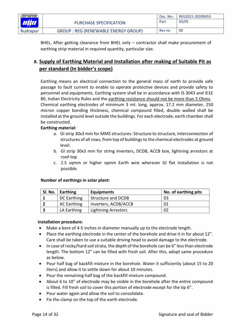
Number of earthings in solar plant:
Sl. No. Earthing Equipments No. of earthing pits
1 DC Earthing Structure and DCDB 03
2 AC Earthing Inverters, ACDB/ACCB 01
3 LA Earthing Lightning Arrestors 02
Installation procedure:
Make a bore of 4-5 inches in diameter manually up to the electrode length.
Place the earthing electrode in the center of the borehole and drive it in for about 12”. Care shall be taken to use a suitable driving head to avoid damage to the electrode.
In case of rocky/hard soil strata, the depth of the borehole can be 6” less than electrode length. The bottom 12” can be filled with fresh soil. After this, adopt same procedure as below.
Pour half bag of backfill mixture in the borehole. Water it sufficiently (about 15 to 20 liters) and allow it to settle down for about 10 minutes.
Pour the remaining half bag of the backfill mixture compound.
About 6 to 10” of electrode may be visible in the borehole after the entire compound is filled. Fill fresh soil to cover this portion of electrode except for the tip 6”.
Pour water again and allow the soil to consolidate.
Fix the clamp on the top of the earth electrode.
PURCHASE SPECIFICATION
Doc. No:- REG2021-20200453
Part 03/05
Rudrapur GROUP : REG (RENEWABLE ENERGY GROUP) Rev no 00
Page 15 of 32 Signature and seal of Bidder
DO NOT DISTRUB the electrode (shaking/rotating etc.) for about 2 to 3 days to enable the compound to settle/set firmly.
Test the earth pit and connect to the electrical circuit.
Check earth resistance. Note: GI/SS bolts, nuts, plain washers shall be used for joining the earth strips.
General points:
i. All items related to earthing viz electrodes, GI flats, hardware etc. are in bidder scope of supply.
ii. GI bolts, nuts, plain washers shall be used. Spring washers shall be zinc/epoxy coated.
iii. Wherever applicable, welding for GI flats shall be carried out using electric arc welding. Both the flats shall be overlapped for the full width where they are in perpendicular direction in same plane. Where the connection is along same line, both flats shall be overlapped for a minimum of 50mm. L-bend with weld length of 50mm minimum shall be adopted wherever overlap length to be ensured.
iv. Resistance of welded joint shall not be more than that of GI flat. v. Welds shall be treated with red oxide for rust protection and then coated with
bitumen compound for corrosion protection. vi. While laying earthing electrodes, adding/mixing of chemical compound and water
around the electrode in the dug hole shall be as per instructions of OEM. Bidder shall ensure visit of OEM engineer to site at the time of installation for proper guidance/ supervision.
vii. Other applicable standards:
IS: 2629: Recommended practice for hot dip galvanizing of iron and steel - IS: 2633: Method for testing uniformity of coating on zinc coated articles
IS: 6745: Methods for determination of mass of zinc coating on zinc coated iron and steel articles.
IS: 513: Cold rolled low carbon steel sheets and strips
IS: 3063: Fasteners single coil rectangular section spring washers
In compliance to Rule 11 and 61 of Indian Electricity Rules, 1956 (as amended up to date), all non-current carrying metal parts shall be earthed with two separate and distinct earth continuity conductors to an efficient earth electrode. All equipment earthing (inverter/DCDB/ACDB/ACCB/LT Panel etc.) shall be earth by using a green colored 4Sqmm Cu wire (with ring type lugs) from equipment respective earthing terminal to earthing strip.
9. Supply and fixing of Name Plate (In bidder’s scope)
The quantity mentioned in the BOQ shall be only to meet specific requirements of the Customer specification/Signage for Name plate. These will be generally of size 250x200 mm of steel material and of thickness 2 mm.
PURCHASE SPECIFICATION
Doc. No:- REG2021-20200453
Part 03/05
Rudrapur GROUP : REG (RENEWABLE ENERGY GROUP) Rev no 00
Page 16 of 32 Signature and seal of Bidder
In addition to this, Bidder shall use danger boards, wherever required, to ensure safety of the persons during the work at site. For all other places where it is required to fix danger plates as per Good Engineering practice and as per Latest Electricity Act stipulations – the same shall be complied with.

PURCHASE SPECIFICATION
Doc. No:- REG2021-20200453
Part 03/05
Rudrapur GROUP : REG (RENEWABLE ENERGY GROUP) Rev no 00
Page 17 of 32 Signature and seal of Bidder
Part B - Special Scope
1. Integration with existing DG supply (Synchronization with DG set) - Supply of required kit with data logger and Installation: - (For Hospital Building) - Bidder’s scope The output power from SPV would be fed to the inverters which converts DC produced by SPV array to AC and feeds it into the main electricity grid after synchronization. In case of grid failure, or low or high voltage, solar PV system shall be out of synchronization and shall be disconnected from the grid. Once the DG set comes into service, PV system shall again be synchronized with DG supply and load requirement would be met to the extent of availability of power. 4 pole isolation of inverter output with respect to the grid/ DG power connection need to be provided.
2. FIRE EXTINGUISHERS: (S&I In bidder’s scope)
The firefighting system for the proposed power plant for fire protection shall be consisting of: Portable fire extinguishers
a) The installation of Fire Extinguishers should confirm to TAC regulations and BIS standards.
Bidder shall provide fire extinguishers as follows for fighting fire electrical wiring, live machinery fires and flammable liquid/ gas as per recommendation by relevant fire safety authority and as per relevant standards IS: 2171 and IS: 10658 marked. Make shall be Safex/ Ceasefire/ Vintex/ Unicare fire safety or any other reputed equivalent subject to BHEL/CUSTOMER approval.
DCP type (ABC) 9Kg designed/tested IS 15683/ IS: 13849 with safety release valve, NRV and CE approved valve. Dry powder IS 14609 with standard accessories.
CO2 type Hand 9 Kg with wheel. Designed/tested IS 2878 complete with hose, screw valve, CO2 gas IS 1522, cylinder IS 7285, valve IS 3224. Tested at 250 Kgf/cm2.
Quantity shall be as per bidder scope of supply (deliverables) in this specification. Note: a) Portable fire extinguishers in the control room for fire caused by electrical short circuits b) Sand buckets in the control room c) The installation of Fire Extinguishers should confirm to TAC regulations and BIS standards. The fire extinguishers shall be provided in the control room housing PCUs as well as on the Roof or site where the PV arrays have been installed.

PURCHASE SPECIFICATION
Doc. No:- REG2021-20200453
Part 03/05
Rudrapur GROUP : REG (RENEWABLE ENERGY GROUP) Rev no 00
Page 18 of 32 Signature and seal of Bidder
3. LA NFC (Supply & Installation In bidder’s scope) The SPV power plants shall be provided with lightning protection. The main aim in this protection shall be to reduce the over voltage to a tolerable value before it reaches the PV or other sub system components. The source of over voltage can be lightning, atmosphere disturbances etc. The entire space occupying the SPV array shall be suitably protected against Lightning by deploying required number of Lightning Arrestors. 4. Necessary foundation / anchoring for holding the lightning conductor in position to be made after giving due consideration to shadow on PV array, maximum wind speed and maintenance requirement at site in future. 5. The lightning conductor shall be earthed through flats and connected to the earth mats as per applicable Indian Standards with earth pits. Minimum two earth pits shall be provided for each lightening arrestor. Lightning protection should be provided as per NFC 17-102:2011 standard. The protection against induced high-voltages shall be provided by the use of metal oxide varistors (MOVs) and suitable earthing such that induced transients find an alternate route to earth.
4. Cleaning (In bidder’s scope)
An appropriate Solar PV Module cleaning & water washing system with complete GI pipes, valves, hose pipes, wipers, mops etc. shall be provided for regular cleaning and water washing of the rooftop Solar PV modules.
Minimum two sets of Microfiber based cleaning tool is to be provided for each
rooftop location. The system shall be specifically designed to take care of the harsh & dusty environment of thermal power plants. Drainage for this system shall be arranged by the bidder. Clean water shall be made available at the nearest point from where bidder has to make necessary pumping & treatment, if required, and piping arrangements for water washing of PV modules
MAINTENANCE REQUIREMENT:
• Easy access shall be provided for all the components in the SPV plant and grid connecting equipments. Maintenance platform has to be provided on each roof for easy inspection of all the equipments. • If special tools are required for maintenance, the bidder has to indicate the same and provide them to NTPC • The bidder has to provide operating and maintenance instruction manual to facilitate effective and safe maintenance.
PURCHASE SPECIFICATION
Doc. No:- REG2021-20200453
Part 03/05
Rudrapur GROUP : REG (RENEWABLE ENERGY GROUP) Rev no 00
Page 19 of 32 Signature and seal of Bidder
5. Operation and Maintenance: (In bidder’s scope)
The installer shall be responsible for operation and maintenance of the Roof top Solar PV system for a period of 2 years (from the date of commissioning & operation acceptance of the whole project by NTPC), during which BHEL/NTPC will monitor the project for effective performance in line with conditions specified elsewhere in the bid document. During this period, the installer shall be responsible for supply of all spare parts as required from time to time for scheduled and preventive maintenance, major overhauling of the plant, replacement of defective modules, inverters, PCU’s etc. and maintaining log sheets for operation detail, deployment of staff for continuous operations and qualified engineer for supervision of O&M work, complaint logging & its attending. Payment for deployed staff during erection, commissioning and O&M period shall meet the local prevalent minimum wages.
Mandatory Spare:
Bidder shall provide following mandatory spares, consumables & various components of Solar PV plant for smooth running during O&M period. Bidder shall also replenish the consumed mandatory spares during the O&M period. The bidder shall also mention the source of supply.
Solar DC cable of 500 M to be provided (Already Included in BOQ)
DC side Surge Arrestor, if applicable – 1 No Following items will be supplied by BHEL as spare items:
Modules – 17 nos.
Inverter – 01 No.(50 kW)
PURCHASE SPECIFICATION
Doc. No:- REG2021-20200453
Part 03/05
Rudrapur GROUP : REG (RENEWABLE ENERGY GROUP) Rev no 00
Page 20 of 32 Signature and seal of Bidder
Part C of BOQ
1. DC Distribution Box: (In bidder’s scope)
DCDB is to be provided in the PV yard for connecting cables from solar string to string
inverter. DCDB shall be dustproof, vermin and weatherproof and shall be made of
GRP/FRP/Powder coated Aluminium/cast aluminium alloy. The material used for boxes shall
be made with UV resistant material to avoid degradation during module life and the sealing
shall comply IP 65 degree of protection.
DCDB shall have suitable cable entry points fitted with cable glands of appropriate sizes for
both incoming and outgoing cables. All wires/cables must be terminated through cable lugs.
Terminals shall be connected to copper bus bar arrangement of proper sizes. Suitable
markings shall be provided on Bus bar for easy identification and cable ferrules shall be fitted
at the cable termination points for identification.
The junction box shall have hinged door with EPDM rubber gasket to prevent water entry
and shall have provision for earthing.
DCDB must comprise of following:
Arrangement for group array isolation.
Test point for subgroup fault location.
Shall have suitable capacity MCBs/MCCB, DC breaker, surge (Type II SPD, MOV), fuse
protection device and suitable reverse blocking diode or bypass diodes to prevent hot spots
in case of cell mismatch or shading.
It shall have DC disconnect switch and proper earthing arrangements.
All fuses shall have DIN rail mountable fuse holders and shall be housed in thermoplastic
IP65 enclosure with transparent covers.
All internal wiring shall be carried out with 1100V grade stranded Cu wires.
String fuses shall be provided in both positive and negative legs of the string cabling. String
fuses shall be of PV category and dedicated to solar applications and conform to IEC 60269-
6 or UL-2579 standards.
The design and components of DCDB must be approved by BHEL prior to
Manufacturing/ordering.
2. ACDB/ACCB : (In bidder’s scope)
a. AC Distribution Panel Board (DPB) shall control the AC power from PCU/ inverter, and
should have necessary surge protection devices, MCB/MCCBs & AC circuit breaker with phase indication of R, Y, B. Interconnection from ACDB to mains at LT Bus bar while in grid tied mode.
b. All switches and the circuit breakers, connectors should conform to IEC 60947, part I, II and III/ IS60947 part I, II and III.
c. The changeover switches, cabling work should be undertaken by the bidder as part of the project.

PURCHASE SPECIFICATION
Doc. No:- REG2021-20200453
Part 03/05
Rudrapur GROUP : REG (RENEWABLE ENERGY GROUP) Rev no 00
Page 21 of 32 Signature and seal of Bidder
d. All the Panel’s shall be metal clad, totally enclosed, rigid, floor mounted, air -insulated, cubical type suitable for operation on three phase / single phase, 415 or 230 volts, 50 Hz
e. The panels shall be designed for minimum expected ambient temperature of 45 degree Celsius, 80 percent humidity and dusty weather.
f. All panels will have protection of IP65 or better. g. It Shall have AC disconnect switch and proper earthing arrangements h. Should conform to Indian Electricity Act and rules (till last amendment). i. All the 415 AC or 230 volts devices / equipment like bus support insulators, circuit
breakers, SPDs, VTs etc., mounted inside the switchgear shall be suitable for continuous operation and satisfactory performance under the following supply conditions
Variation in supply voltage +/- 10%
Variation in supply frequency +/- 3 Hz
BOM FOR ACDB 30 KWp S.No ITEM DESCRIPTION DIMENSIONS MAKE QTY
1 Enclosure ACDB box should comply IP-65 or above
Reputed 1
2 R,Y,B Indication Lamp with Control MCB
Reputed 3
3 MCCB Input1 4P, 63A,25kA L&T/Schneider/ABB 1
4 SPD-Type II Three Phase Phoenix/CITEL 1
5 Earth Terminal Block 16 Sqmm Elmex/
Connectwell/Reputed 1
6 Dinrail Phoenix/Hex/ Reputed 1
7 Cable Gland Input (4x10Sqmm)
Metal Double Compression
Jigo/Reputed 1
8 Cable Gland Output (4x25Sqmm)
Metal Double Compression
Jigo/Reputed 1
9 Earth Gland Reputed 1
10 Indicating Stickers Reputed 1
11 Screws, Cable, Lugs, etc. Hex/ Reputed 1
BOM FOR ACCB 70 KW (2 in 1 out) S.No ITEM DESCRIPTION DIMENSIONS MAKE QTY
1 Enclosure CRCA SHEET IP65/66 Reputed 1
2 MCCB - input 1 with spreader 4P, 100A,25kA L&T/Schneider/ABB/Havells/C&S 1
3 MCCB - input 2 with spreader 4P, 40A,10kA L&T/Schneider/ABB/Havells/C&S 1
4 MCCB- Output with spreader 4P, 125A,25kA L&T/Schneider/ABB/Havells/C&S 1
5 Bus Bar -Copper 150A Reputed 4
6 Earth Terminal Block 16 Sqmm Elmex/ Connectwell/Reputed 1

PURCHASE SPECIFICATION
Doc. No:- REG2021-20200453
Part 03/05
Rudrapur GROUP : REG (RENEWABLE ENERGY GROUP) Rev no 00
Page 22 of 32 Signature and seal of Bidder
7 Cable Gland Input Polyamide Jigo/Reputed 2
8 Cable Gland Output Polyamide Reputed 1
9 Earth Gland Polyamide Reputed 1
10 Indicating Stickers Reputed 1
11 Screws, Cable, Lugs, etc.. Hex/ Reputed 1
BOM FOR ACCB 80 KW (2 in 1 out) S.No ITEM DESCRIPTION DIMENSIONS MAKE QTY
1 Enclosure CRCA SHEET IP65/66 Reputed 1
2 MCCB - input 1 with spreader 4P, 100A,25kA L&T/Schneider/ABB/Havells/C&S 1
3 MCCB - input 2 with spreader 4P, 63A,25kA L&T/Schneider/ABB/Havells/C&S 1
4 MCCB- Output with spreader 4P, 125A,25kA L&T/Schneider/ABB/Havells/C&S 1
5 Bus Bar -Copper 150A Reputed 4
6 Earth Terminal Block 16 Sqmm Elmex/ Connectwell/Reputed 1
7 Cable Gland Input Polyamide Jigo/Reputed 2
8 Cable Gland Output Polyamide Reputed 1
9 Earth Gland Polyamide Reputed 1
10 Indicating Stickers Reputed 1
11 Screws, Cable, Lugs, etc.. Hex/ Reputed 1
BOM FOR ACCB 100 KW (2 in 1 out) S.No ITEM DESCRIPTION DIMENSIONS MAKE QTY
1 Enclosure CRCA SHEET IP65/66 Reputed 1
2 MCCB - input 1 with spreader
4P, 100A,25kA L&T/Schneider/ABB/Havells/C&S 1
3 MCCB - input 2 with spreader
4P, 100A,25kA L&T/Schneider/ABB/Havells/C&S 1
4 MCCB- Output with spreader
4P, 200A,25kA L&T/Schneider/ABB/Havells/C&S 1
5 Bus Bar -Copper 200A Reputed 4
6 Earth Terminal Block 16 Sqmm Elmex/ Connectwell/Reputed 1
7 Cable Gland Input Polyamide Jigo/Reputed 2
PURCHASE SPECIFICATION
Doc. No:- REG2021-20200453
Part 03/05
Rudrapur GROUP : REG (RENEWABLE ENERGY GROUP) Rev no 00
Page 23 of 32 Signature and seal of Bidder
8 Cable Gland Output Polyamide Reputed 1
9 Earth Gland Polyamide Reputed 1
10 Indicating Stickers Reputed 1
11 Screws, Cable, Lugs, etc.. Hex/ Reputed 1
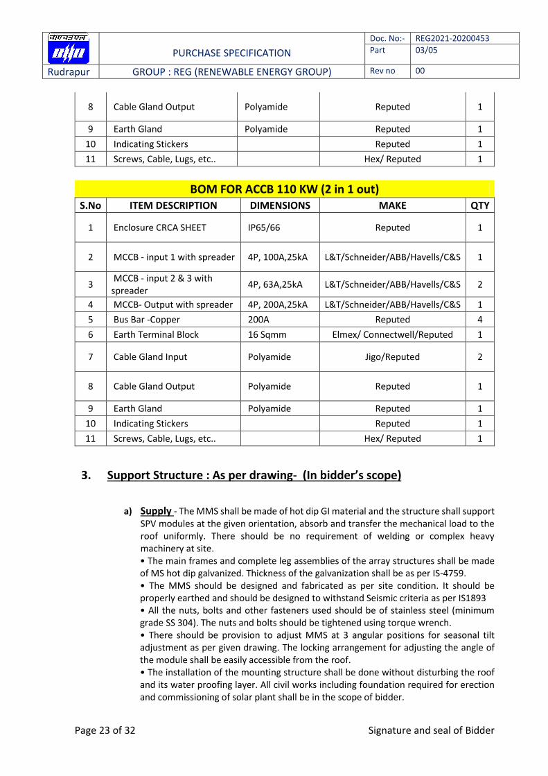
BOM FOR ACCB 110 KW (2 in 1 out) S.No ITEM DESCRIPTION DIMENSIONS MAKE QTY
1 Enclosure CRCA SHEET IP65/66 Reputed 1
2 MCCB - input 1 with spreader 4P, 100A,25kA L&T/Schneider/ABB/Havells/C&S 1
3 MCCB - input 2 & 3 with spreader
4P, 63A,25kA L&T/Schneider/ABB/Havells/C&S 2
4 MCCB- Output with spreader 4P, 200A,25kA L&T/Schneider/ABB/Havells/C&S 1
5 Bus Bar -Copper 200A Reputed 4
6 Earth Terminal Block 16 Sqmm Elmex/ Connectwell/Reputed 1
7 Cable Gland Input Polyamide Jigo/Reputed 2
8 Cable Gland Output Polyamide Reputed 1
9 Earth Gland Polyamide Reputed 1
10 Indicating Stickers Reputed 1
11 Screws, Cable, Lugs, etc.. Hex/ Reputed 1
3. Support Structure : As per drawing- (In bidder’s scope)
a) Supply - The MMS shall be made of hot dip GI material and the structure shall support
SPV modules at the given orientation, absorb and transfer the mechanical load to the roof uniformly. There should be no requirement of welding or complex heavy machinery at site. • The main frames and complete leg assemblies of the array structures shall be made of MS hot dip galvanized. Thickness of the galvanization shall be as per IS-4759. • The MMS should be designed and fabricated as per site condition. It should be properly earthed and should be designed to withstand Seismic criteria as per IS1893 • All the nuts, bolts and other fasteners used should be of stainless steel (minimum grade SS 304). The nuts and bolts should be tightened using torque wrench. • There should be provision to adjust MMS at 3 angular positions for seasonal tilt adjustment as per given drawing. The locking arrangement for adjusting the angle of the module shall be easily accessible from the roof. • The installation of the mounting structure shall be done without disturbing the roof and its water proofing layer. All civil works including foundation required for erection and commissioning of solar plant shall be in the scope of bidder.

PURCHASE SPECIFICATION
Doc. No:- REG2021-20200453
Part 03/05
Rudrapur GROUP : REG (RENEWABLE ENERGY GROUP) Rev no 00
Page 24 of 32 Signature and seal of Bidder
b) Installation - Bidder shall do the installation of the Module Mounting as per approved layout design of BHEL provided along with the tender. Required number of nuts and bolts for the erection of Modules shall be supplied by bidder. Wherever, welding is carried out, bidder shall arrange for proper grinding and cleaning of the weld surfaces, followed by application of Metal primer and Metallic aluminum paint. Pre-Galvanized parts shall be sprayed with Zinc spray after work. Required number of nuts and bolts for the installation of MMS shall be supplied by bidders. Note: NUTS, BOLTS AND PLAIN & SPRING WASHERS shall be made of SS 304.
4. DC Cables: (In bidder’s scope) – Makes as per attached make list
Cables for use at the DC-side of PV system shall meet the requirements of TUV standard 2 PfG 1190/5.18 or EN-50618 or other equivalent standard. Copper cables of reputed make shall only be used from PV array to inverter. Aluminium cables can be used for AC power evacuation from inverter. The permissible voltage drop from SPV generator to the inverter shall not be more than 2%.
The Specification of wiring material of PV Power plant shall include but not limited to the
following:
Sl. No Item Description
4.1 DC Cable From PV module to DCDB and inverter
4.1.1 Type 1.1kV grade heavy duty PVC insulated, Double sheathed, UV
protected XLPO stranded copper cables as per IS: 7098 (Part I & II)
– 1976 or IS 1554 or IS9537/IEC60227/IS694 or Solar DC Cable as
per BS EN 50618
4.1.2 Size 1 core x 4 sqmm. Unarmored
4.1.3 Laying The cable must be laid through PVC conduit /GI pipe/ cable tray, as
applicable, on roof and indoor. In case of using metallic pipe as
conduit proper grounding of the conduit must be done.
Procedure of cable laying: As per Sl. No. 5 of Part A
Note: Bidder will have to raise inspection call for DC cables to BHEL before dispatching the cable. BHEL/NTPC
will inspect the cable at the manufacturer’s works. Dispatch Clearance shall be issued as per Joint
Inspection Report.
5. AC Cables (Copper): (In bidder’s scope) – Makes as per attached make list:
The Specification of wiring material of PV Power plant shall include but not limited to the following:

PURCHASE SPECIFICATION
Doc. No:- REG2021-20200453
Part 03/05
Rudrapur GROUP : REG (RENEWABLE ENERGY GROUP) Rev no 00
Page 25 of 32 Signature and seal of Bidder
5.1 AC Cable (Copper) From inverter to ACDB
5.1.1 Type 1.1kV grade heavy duty PVC insulated galvanized strip/wire armored XLPE stranded Cu conductor cables as per IS: 7098 (Part I & II) – 1976 or IS 1554 or IS9537/IEC60227/IS694.
5.1.2 Size As per attached SLD
5.1.3 Laying The cable must be laid through PVC conduit /GI pipe/ cable tray on roof and indoor. In case of using metallic pipe as conduit proper grounding of the conduit must be done.
Procedure of cable laying: Same as Sl. No. 5 of part A
6. AC Cables (Aluminium): (In bidder’s scope) – Makes as per attached make list:
The Specification of wiring material of PV Power plant shall include but not limited to the following:
5.1 AC Cable
(Aluminium)
From ACDB to LT Panel/ Distribution board
5.1.1 Type 1.1kV grade heavy duty PVC insulated galvanized strip/wire armored XLPE stranded Al conductor cables as per IS: 7098 (Part I & II) – 1976 or IS 1554 or IS9537/IEC60227/IS694.
5.1.2 Size As per attached SLD
5.1.3 Laying The cable must be laid through PVC conduit /GI pipe/ cable tray on roof and indoor. In case of using metallic pipe as conduit proper grounding of the conduit must be done.
Procedure of cable laying: Same as Sl. No. 5 of part A
7. Weather monitoring Station
Solar Irradiance: An integrating Pyranometer (Class II or better) shall be provided, with the sensor mounted on a Horizontal plane at a shadow free suitable location near solar arrays.
Temperature: Temperature probes for recording the PV Cell temperature shall be provided at one of the modules at shade free location
Wind Speed measuring instrument
PURCHASE SPECIFICATION
Doc. No:- REG2021-20200453
Part 03/05
Rudrapur GROUP : REG (RENEWABLE ENERGY GROUP) Rev no 00
Page 26 of 32 Signature and seal of Bidder
PURCHASE SPECIFICATION
Doc. No:- REG2021-20200453
Part 03/05
Rudrapur GROUP : REG (RENEWABLE ENERGY GROUP) Rev no 00
Page 27 of 32 Signature and seal of Bidder
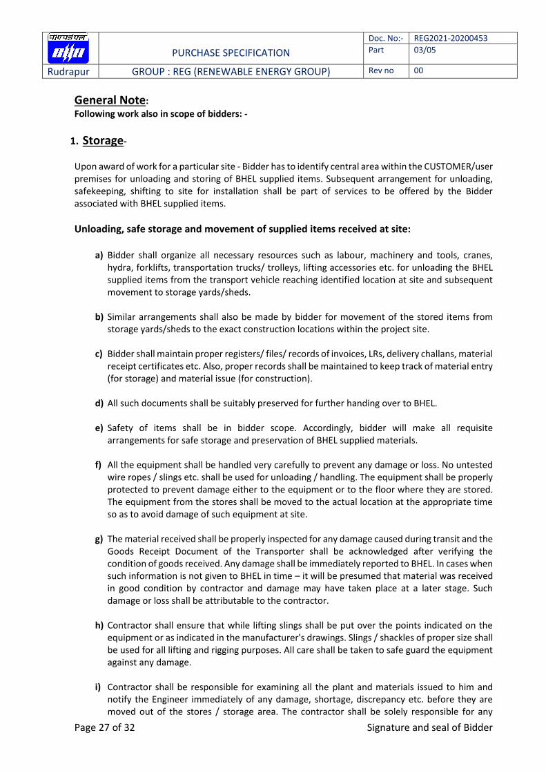
General Note:
Following work also in scope of bidders: -
1. Storage-
Upon award of work for a particular site - Bidder has to identify central area within the CUSTOMER/user premises for unloading and storing of BHEL supplied items. Subsequent arrangement for unloading, safekeeping, shifting to site for installation shall be part of services to be offered by the Bidder associated with BHEL supplied items.
Unloading, safe storage and movement of supplied items received at site:
a) Bidder shall organize all necessary resources such as labour, machinery and tools, cranes, hydra, forklifts, transportation trucks/ trolleys, lifting accessories etc. for unloading the BHEL supplied items from the transport vehicle reaching identified location at site and subsequent movement to storage yards/sheds.
b) Similar arrangements shall also be made by bidder for movement of the stored items from
storage yards/sheds to the exact construction locations within the project site.
c) Bidder shall maintain proper registers/ files/ records of invoices, LRs, delivery challans, material receipt certificates etc. Also, proper records shall be maintained to keep track of material entry (for storage) and material issue (for construction).
d) All such documents shall be suitably preserved for further handing over to BHEL.
e) Safety of items shall be in bidder scope. Accordingly, bidder will make all requisite arrangements for safe storage and preservation of BHEL supplied materials.
f) All the equipment shall be handled very carefully to prevent any damage or loss. No untested wire ropes / slings etc. shall be used for unloading / handling. The equipment shall be properly protected to prevent damage either to the equipment or to the floor where they are stored. The equipment from the stores shall be moved to the actual location at the appropriate time so as to avoid damage of such equipment at site.
g) The material received shall be properly inspected for any damage caused during transit and the Goods Receipt Document of the Transporter shall be acknowledged after verifying the condition of goods received. Any damage shall be immediately reported to BHEL. In cases when such information is not given to BHEL in time – it will be presumed that material was received in good condition by contractor and damage may have taken place at a later stage. Such damage or loss shall be attributable to the contractor.
h) Contractor shall ensure that while lifting slings shall be put over the points indicated on the equipment or as indicated in the manufacturer's drawings. Slings / shackles of proper size shall be used for all lifting and rigging purposes. All care shall be taken to safe guard the equipment against any damage.
i) Contractor shall be responsible for examining all the plant and materials issued to him and notify the Engineer immediately of any damage, shortage, discrepancy etc. before they are moved out of the stores / storage area. The contractor shall be solely responsible for any
PURCHASE SPECIFICATION
Doc. No:- REG2021-20200453
Part 03/05
Rudrapur GROUP : REG (RENEWABLE ENERGY GROUP) Rev no 00
Page 28 of 32 Signature and seal of Bidder
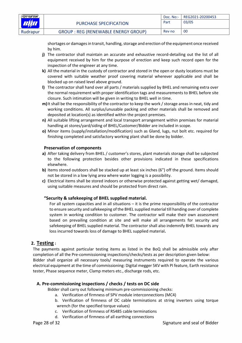
shortages or damages in transit, handling, storage and erection of the equipment once received by him.
j) The contractor shall maintain an accurate and exhaustive record-detailing out the list of all equipment received by him for the purpose of erection and keep such record open for the inspection of the engineer at any time.
k) All the material in the custody of contractor and stored in the open or dusty locations must be covered with suitable weather proof covering material wherever applicable and shall be blocked up on raised level above ground.
l) The contractor shall hand over all parts / materials supplied by BHEL and remaining extra over the normal requirement with proper identification tags and measurements to BHEL before site closure. Such intimation will be given in writing to BHEL well in time.
m) It shall be the responsibility of the contractor to keep the work / storage areas in neat, tidy and working conditions. All surplus/unusable packing and other materials shall be removed and deposited at location(s) as identified within the project premises.
n) All suitable lifting arrangement and local transport arrangement within premises for material handling at stores/yard/siding of BHEL/Customer/Bidder are included in scope.
o) Minor items (supply/installation/modification) such as Gland, lugs, nut bolt etc. required for finishing completed and satisfactory working plant shall be done by bidder.
Preservation of components a) After taking delivery from BHEL / customer’s stores, plant materials storage shall be subjected
to the following protection besides other provisions indicated in these specifications elsewhere.
b) Items stored outdoors shall be stacked up at least six inches (6") off the ground. Items should not be stored in a low lying area where water logging is a possibility.
c) Electrical items shall be stored indoors or otherwise protected against getting wet/ damaged, using suitable measures and should be protected from direct rain.
“Security & safekeeping of BHEL supplied material.
For all system capacities and in all situations – it is the prime responsibility of the contractor to ensure security and safekeeping of the BHEL supplied material till handing over of complete system in working condition to customer. The contractor will make their own assessment based on prevailing condition at site and will make all arrangements for security and safekeeping of BHEL supplied material. The contractor shall also indemnify BHEL towards any loss incurred towards loss of damage to BHEL supplied material.
2. Testing :
The payments against particular testing items as listed in the BoQ shall be admissible only after completion of all the Pre-commissioning inspections/checks/tests as per description given below: Bidder shall organize all necessary tools/ measuring instruments required to operate the various electrical equipment at the time of commissioning: Digital megger 5KV with PI feature, Earth resistance tester, Phase sequence meter, Clamp meters etc., discharge rods, etc.
A. Pre-commissioning inspections / checks / tests on DC side
Bidder shall carry out following minimum pre-commissioning checks: a. Verification of firmness of SPV module interconnections (MC4) b. Verification of firmness of DC cable terminations at string inverters using torque wrench (for the specified torque values)
c. Verification of firmness of RS485 cable terminations d. Verification of firmness of all earthing connections
PURCHASE SPECIFICATION
Doc. No:- REG2021-20200453
Part 03/05
Rudrapur GROUP : REG (RENEWABLE ENERGY GROUP) Rev no 00
Page 29 of 32 Signature and seal of Bidder
e. Cable megger/ continuity check for all DC power cables f. Measurement of open circuit voltage of individual strings g. Measurement of earth resistance at individual earth pits of solar array: (a) as disconnected from earth mat grid and also, (b) as connected to earth mat grid
h. Submission of test reports to BHEL for acceptance.
B. Pre-commissioning inspections/checks/tests on AC side.
Basic checks Tightness checks:
Terminations of AC power cables at string inverters, data loggers, ACCB box, LTPDB panels.
Terminations of Control/ Instrumentation/ Data/ Communication cables wherever applicable.
Terminations of earthing at all electrical equipments/ panels. 4) Terminations of earth chambers of bidder scope
Electrical continuity checks Megger (1kV) checks for all 1.1kV grade cables AC/DC supply checks at TBs of all electrical panels/ DBs.
C. Pre-commissioning electrical tests:
String inverters
DC side open circuit voltage
Bidder to provide technician support to service engineer of string inverters for all other pre-commissioning tests as per OEM checklist
D. Earth resistance measurements for all chambers of bidder scope
With electrode connected to grid
Without connecting electrode to grid
E. Performance Ratio and other Tests- Bidder has to clean PV modules timely to meet PR values as mentioned in attached NTPC scope of work.
3. Tools & Tackle and Spares
After completion of installation & commissioning of the power plant, necessary tools & tackles are to be provided free of cost by the bidder for maintenance purpose. List of tools and tackles to be supplied by the bidder for approval of specifications and make from [NAME OF THE ORGANISATION]/ owner.
Bidder shall provide following mandatory spares, consumables & various components of Solar PV plant for smooth running during O&M period. Bidder shall also replenish the consumed mandatory spares during the O&M period. The bidder shall also mention the source of supply.
Solar DC cable of 500 M to be provided
DC side Surge Arrestor, if applicable – 1 No
PURCHASE SPECIFICATION
Doc. No:- REG2021-20200453
Part 03/05
Rudrapur GROUP : REG (RENEWABLE ENERGY GROUP) Rev no 00
Page 30 of 32 Signature and seal of Bidder
4. Safety Measure
The bidder shall take entire responsibility for electrical safety of the installation(s) including connectivity with the grid and follow all the safety rules & regulations applicable as per Electricity Act, 2003 and CEA guidelines etc.
5. Danger boards and Signage:
Danger boards should be provided as and where necessary as per IE Act. /IE rules as amended up to date. Three signage shall be provided one each at battery –cum- control room, solar array area and main entry from administrative block. Text of the signage may be finalized in consultation with [NAME OF THE ORGANISATION]/ owner.
6. Connectivity:
The maximum capacity for interconnection with the grid at a specific voltage level shall be as specified in the Distribution Code/Supply Code of the State and amended from time to time. Following criteria have been suggested for selection of voltage level in the distribution system for ready reference of the solar suppliers. Plant Capacity Connecting voltage Up to 10 kW 240V-single phase or 415V-three phase at the option of the consumer Above 10kW and up to 100 kW 415V – three phase Above 100kW At HT/EHT level (11kV/33kV/66kV) as per DISCOM rules
a) The maximum permissible capacity for rooftop shall be 1 MW for a single net metering point. b) Utilities may have voltage levels other than above, DISCOMS may be consulted before
finalization of the voltage level and specification be made accordingly. c) For large PV system (Above 100 kW) for commercial installation having large load, the solar
power can be generated at low voltage levels and stepped up to 11 kV level through the step up transformer. The transformers and associated switchgear would require to be provided by the SPV bidders.
d) The bidirectional electronic energy meter (0.5 S class) shall be installed for the measurement of import/Export of energy.
e) The bidder must take approval/NOC from the Concerned DISCOM for the connectivity, technical feasibility, and synchronization of SPV plant with distribution network and submit the same to BHEL before commissioning of SPV plant.
Note: If Step up transformer is not required, existing transformer can be used for connectivity. Connection to Transformer if required shall be done by Bidder.
7. Training personnel It is the absolute responsibility of bidder to ensure imparting of necessary training to their personnel to get them acquainted with the operations of various electrical and mechanical equipment of the power plant. For this purpose, bidder shall identify the personnel well in advance and involve them during installation and commissioning stages so that they become well versed with various functional aspects of the power plant. Availability of personnel at power plant
Bidder shall ensure that operating staff are present in the power plant during 6:30 AM – 6:30 PM every day. (staggered shift to cover duty time)
PURCHASE SPECIFICATION
Doc. No:- REG2021-20200453
Part 03/05
Rudrapur GROUP : REG (RENEWABLE ENERGY GROUP) Rev no 00
Page 31 of 32 Signature and seal of Bidder
Bidder shall ensure that certain minimum operating staff are present at the power plant even on festivals, public holidays and any other unique occasions so that the plant is run under competent supervision on all days.
Personnel shall, strictly, not use any part of the power plant for their personal /residential purposes. Their presence at the plant shall, strictly, be meant only for the purpose of operation and maintenance of plant.

PURCHASE SPECIFICATION
Doc. No:- REG2021-20200453
Part 03/05
Rudrapur GROUP : REG (RENEWABLE ENERGY GROUP) Rev no 00
Page 32 of 32 Signature and seal of Bidder
LIST OF ENCLOSURES:
Following enclosure makes the part of REG2021-20200453
a) SPV Module Data Sheet
b) SCC
c) GCC
d) FQP, inspection check list.
e) MMS drawing (3 and 5 Panels) & Manufacturing drawing of MMS
f) Make list
g) Earthing procedure
h) Module layout and SLD
i) NTPC Scope of work (As applicable)
j) MQP of NTPC (As applicable)
Note: Anything not mentioned in the purchase specification document or differs with NTPC
specification shall be followed as per NTPC specification attached with the tender documents.