Embed Size (px)
Citation preview

Thielert Aircraft Engines GmbH
Platenenstr. 14
D - 09350 Lichtenstein
Tel. +49-(0)37204/ 696-0
Fax +49-(0)37204/ 696-2912
www.centurion-engines.com
Supplement
Pilot´s Operating Handbook
for the
Piper PA-28-140 - Cherokee CruiserPiper PA-28-150/160/180 - CherokeePiper PA-28-151 - Cherokee WarriorPiper PA-28-161 - Cadet, Warrior II & III
Equipped with TAE 125 Installation
Issue 4
This supplement must be attached to the EASA approved Pilot´s
Operating Handbook when the TAE 125 installation has been installed
in accordance with STC EASA A.S.01632 or EASA STC 10014364.
The information contained in this supplement supersede or add to the
EASA approved Pilot´s Operating Handbook only as set forth herein.
For limitations, procedures, performance and loading information not
contained in this supplement, consult the EASA approved Pilot´s
Operating Handbook.
This supplement Pilot's Operating Handbook is approved with EASA
STC 10014364.
MODEL No.
SERIAL No.
REGISTRATION No.
TAE-Nr.: 40-0310-40024

This page is intentionally left blank

Supplement POH
PA-28-140/150/151/160/161/180
LOG OF REVISIONS
Page iii
Issue 4
Revision 4, March 2012


Supplement POH
PA-28-140/150/151/160/161/180
LIST OF EFFECTIVE SECTIONS
Approval
The content of approved chapters is approved by EASA. All
other content is approved by TAE under the authority of EASA
DOA No. EASA.21J.010 in accordance with Part 21.
General remark
The content of this POH supplement is developed on basis of
the EASA approved POH.
Sections Issue/ Revision Date
0 4/4 March 2012
1 4/3 March 2012
2 4/3 March 2012
3 4/3 June 2011
4 4/2 March 2012
5 4/1 April 2011
6 4/0 Feb. 2010
7 4/2 June 2011
8 4/1 June 2011
Page v
Issue 4
Revision 4, March 2012

Supplement POH
PA-28-140/150/151/160/161/180
This page is intentionally left blank
Page vi
Issue 4
Revision 4, March 2012

Supplement POH
PA-28-140/150/151/160/161/180
TABLE OF CONTENTS
SECTION 1 ................GENERAL
(a non-approved section)
SECTION 2 ................LIMITATIONS
(an approved section)
SECTION 3 ...............EMERGENCY PROCEDURES
(a non-approved section)
SECTION 4 ................NORMAL PROCEDURES
(a non-approved section)
SECTION 5 ................PERFORMANCE
(a non-approved section)
SECTION 6 ................WEIGHT AND BALANCE
(a non-approved section)
SECTION 7 ................DESCRIPTION AND OPERATION OF
THE AIRPLANE AND ITS SYSTEMS
(a non-approved section)
SECTION 8 ................AIRPLANE HANDLING, SERVICING
AND MAINTENANCE
(a non-approved section)
Page vii
Issue 4
Revision 2, April 2011

Supplement POH
PA-28-140/150/151/160/161/180
CONVERSION TABLES
VOLUME
Unit [Abbr.]Conversion factorSI to US / Imperial
Conversion factorUS / Imperial to Si
Liter [l]
US gallon [US gal]US quart [US qt]Imperial gallon [lmp gal]Cubic inch [in³]
[l] / 3.7854 = [US gal] [l] / 0.9464 = [US qt] [l] / 4.5459 = [[lmp gal] [l] x 61.024 = [in³]
[US gal] x 3.7854 = [l][[US qt] x 0.9464 = [l][[lmp gal] x 4.5459 = [l][in³] / 61.024 = [l]
TORQUE
Unit [Abbr.]Conversion factorSI to US / Imperial
Conversion factorUS / Imperial to Si
Kilopondmeter [kpm]
Foot pound [ft.lb]Inch pound [in.lb]
[kpm] x 7.2331 = [ft.lb][kpm] x 86.7962 = [in.lb]
[ft.lb] / 7.2331 = [kpm][in.lb] / 86.7962 = [kpm]
TEMPERATURE
Unit [Abbr.]Conversion factorSI to US / Imperial
Conversion factorUS / Imperial to Si
Degree Celsius [ºC]Degree Fahrenheit [ºF]
[ºC] x 1.8 + 32 = [ºF] ([ºF] - 32) / 1.8 = [ºC]
SPEED
Unit [Abbr.]Conversion factorSI to US / Imperial
Conversion factorUS / Imperial to Si
Kilometers per hour [km/h]
Meters per second [m/s]Miles per hour [mph]Knots [kts]Feet per minute [fpm]
[km/h] / 1.852 = [kts] [km/h] / 1.609 = [mph] [m/s] / 196.85 = [fpm]
[mph] x 1.609 = [km/h][kts] x 1.852 = [km/h][fpm] / 196.85 = [m/s]
Page viii
Issue 4
Revision 2, April 2011

Supplement POH
PA-28-140/150/151/160/161/180
PRESSURE
Unit [Abbr.]Conversion factorSI to US / Imperial
Conversion factorUS / Imperial to Si
Bar [bar]Hectopascal [hpa]=Millibar [mbar]
Pounds per square inch [psi] inches of mercury column [inHg]
[bar] x 14.5038 = [psi][hpa] / 33.864= [inHg]
[mbar] / 33.864 = [inHg]psi] / 14.5038 = [bar][inHg] x 33.864 = [hPa]
[inHg] x 33.864 = [mbar]
MASS
Unit [Abbr.]Conversion factorSI to US / Imperial
Conversion factorUS / Imperial to Si
Kilogramm [kg]Pound [lb]
[kg] / 0.45359 = [lb][lb] x 0.45359 = [kg]
LENGTH
Unit [Abbr.]Conversion factorSI to US / Imperial
Conversion factorUS / Imperial to Si
Meter [m]Millimeter [mm]Kilometer [km]
Inch [in]Foot [ft]Nautical mile [nm]Statute mile [sm]
[m] / = 0.3048 [ft] [mm] / = 25.4 [in] [km] / = 1.852 [nm] [km] / = 1.609 [sm]
[in] x 25.4 = [mm][ft] x 0.3048 = [m][nm] x 1.852 = [km][sm] x 1.609 = [km]
FORCE
Unit [Abbr.]Conversion factorSI to US / Imperial
Conversion factorUS / Imperial to Si
Newton [N]Decanewton [daN]Pound [lb]
[N] / 4.448 = [lb][daN] / 0.4448 = [lb]
[lb] x 4.448 = [N][lb] x 0.4448 = [daN]
Page ix
Issue 4
Revision 2, April 2011

Supplement POH
PA-28-140/150/151/160/161/180
°C °F
-50
-40
-30
-20
-10
0
10
20
30
40
50
60
70
80
90
100
110
120
130
140
150
-58
-38
-18
2
22
42
62
82
102
122
142
162
182
202
222
242
262
282
302
Page x
Issue 4
Revision 2, April 2011

Supplement POH
PA-28-140/150/151/160/161/180
Page xi
Issue 4
Revision 2, April 2011

Supplement POH
PA-28-140/150/151/160/161/180
ABBREVIATIONS
TAE Thielert Aircraft Engines GmbH, developing
and manufacturing company of TAE 125
FADEC Full Authority Digital Engine Control
CED 125 Compact Engine Display
Multifunctional instrument for indication of
engine data of TAE 125
AED 125 Auxiliary Engine Display
Multifunctional instrument for indication of
engine and airplane data
Page xii
Issue 4
Revision 2, April 2011

Supplement POH
PA-28-140/150/151/160/161/180
SECTION 1GENERAL
CONVENTIONS IN THIS HANDBOOK
This manual contains following conventions and warnings. They should be strictly followed to rule out personal injury, property damage, impairment to the aircraft's operating safety or damage to it as a result of improper functioning.
UPDATE AND REVISION OF THE MANUAL
� WARNING: Non-compliance with these safety rules
could lead to injury or even death.
� CAUTION: Non-compliance with these special notes
and safety measures could cause damage
to the engine or to the other components.
� Note: Information added for a better
understanding of an instruction.
� WARNING: A safe operation is only assured with an up
to date POH supplement. Information about
actual POH supplement issues and
revisions are published in the TAE Service
Bulletin TM TAE 000-0004.
� Note: The TAE-No. of this POH supplement is
published on the cover sheet of this
supplement.
Page 1-1
Issue 4
Revision 3, March 2012
Supplement POH
PA-28-140/150/151/160/161/180
ENGINE
Engine manufacturer:............... Thielert Aircraft Engines GmbH
Engine model: ........................... TAE 125-01 or TAE 125-02-99
The TAE 125-02-99 is the successor of the 125-01. Both engine
variants have the same power output and the same propeller
speeds but different displacement. While the TAE 125-01 has
1689 ccm, the TAE 125-02 has 1991 ccm. Both TAE 125 engine
variants are liquid cooled in-line four-stroke 4-cylinder motor
with DOHC (double overhead camshaft) and are direct Diesel
injection engines with common-rail technology and
turbocharging. Both engine variants are controlled by a
FADEC system. The propeller is driven by a built-in gearbox
with mechanical vibration damping and overload release. Both
engines have an electrical self starter and an alternator.
Due to this specific characteristic, all of the information from the
flight manual recognized by EASA are no longer valid with
reference to:
• carburetor and carburetor pre-heating
• ignition magnetos and spark plugs, and
• mixture control and priming system
� WARNING The engine requires an electrical power
source for operation. If the main battery and
alternator fail simultaneously, the engine
will only operate on A-FADEC for maximum
30 minutes on FADEC backup battery
power (if installed). Therefore, it is
important to pay attention to indications of
alternator failure.
Page 1-2
Issue 4
Revision 3, March 2012

Supplement POH
PA-28-140/150/151/160/161/180
PROPELLER
Manufacturer:.........................MT Propeller Entwicklung GmbH
Model: ........................................................... MTV-6-A/187-129
Number of blades:.................................................................... 3
Diameter: ..........................................................1.87 m (73.6 in)
Type: ......................... Variable-pitch propeller (constant speed)
LIQUIDS
Fuel: ........................................................JET A-1 (ASTM 1655)
Alternatives: ........................................... JET A (ASTM D 1655)
..........................................Fuel No.3 (GB 6537-2006)
............................ JP-8, JP-8+100 (MIL-DTL-83133E)
................................................... Diesel (DIN EN 590)
Only TAE 125-02-99 (C2.0):
.............................................. TS-1 (GOST 10227-86)
...........................TS-1 (GSTU 320.00149943.011-99)
Engine oil: ......................................... AeroShell Oil Diesel Ultra
...................................... AeroShell Oil Diesel 10W-40
...............................................Shell Helix Ultra 5W-40
...............................................Shell Helix Ultra 5W-30
Gearbox oil:.............................. Shell Spirax S6 GXME 75W-80
.......................................... Shell Spirax S4 G 75W-90
....................... Shell Getriebeöl EP 75W-90 API GL-4
............................................. Shell Spirax EP 75W-90
..................................Shell Spirax GSX 75W-80 GL-4
� CAUTION: Use of unapproved fuels may result in
damage to the engine and fuel system
components, resulting in possible engine
failure.
� CAUTION: Use the approved oil with exact designation
only.
Page 1-3
Issue 4
Revision 3, March 2012

Supplement POH
PA-28-140/150/151/160/161/180
Coolant:................Water/Radiator Protection at a ratio of 50:50
Radiator Protection: ............. BASF Glysantin Protect Plus/G48
......................................... Mobil Antifreeze Extra/G48
........................................ESSO Antifreeze Extra/G48
............... Comma Xstream Green - Concentrate/G48
................................................... Zerex Glysantin G48
� WARNING: The engine must not be started under any
circumstances if any fluid level is too low.
� CAUTION: Normally it is not necessary to fill the
cooling liquid or gearbox oil between
maintenance intervals. If the level is too
low, please notify the TAE service
department immediately.
� Note: The freezing point of the coolant is
-36°C (-32.8°F).
Page 1-4
Issue 4
Revision 3, March 2012

Supplement POH
PA-28-140/150/151/160/161/180
SECTION 2LIMITATIONS
AIRSPEED LIMITATIONS
No change
AIRSPEED INDICATIOR MARKINGS
No change
ENGINE OPERATING LIMITS
Engine manufacturer:............... Thielert Aircraft Engines GmbH
Engine model: .......................... TAE 125-01 or TAE 125-02-99
Take-off and Max. continuous power:.............. 99 kW (135 HP)
Take-off and Max. continuous RPM:...........................2300 rpm
Propeller Manufacturer: .........MT Propeller Entwicklung GmbH
Propeller Model:............................................ MTV-6-A/187-129
Number of blades:.................................................................... 3
Propeller Diameter: ...........................................1.87 m (73.6 in)
� WARNING The engine requires an electrical power
source for operation. If the main battery and
alternator fail simultaneously, the engine
will only operate on A-FADEC for maximum
30 minutes on FADEC backup battery
power (if installed). Therefore, it is
important to pay attention to indications of
alternator failure.
� WARNING It is not allowed to start up the engine using
external power. If starting the engine is not
possible using battery power, the condition
of the battery must be verified before flight.
Page 2-1
Issue 4
Revision 3, March 2012

Supplement POH
PA-28-140/150/151/160/161/180
Engine operating limits for take-off and continuous operation:
Oil temperature
Minimum engine starting temperature: ................... -32°C (-25.6°F)
Minimum operating limit temperature: ........................50°C (122°F)
Maximum operating limit temperature: .....................140°C (284°F)
Coolant temperature
Minimum engine starting temperature: ................... -32°C (-25.6°F)
Minimum operating limit temperature: ........................60°C (140°F)
Maximum operating limit temperature: .....................105°C (221°F)
Gearbox temperature
Minimum operating limit temperature: ....................... -30°C (-22°F)
Maximum operating limittemperature: ......................120°C (248°F)
� Note: This change of the original aircraft is
certified up to an altitude of 14,000 ft.
� Note: In the absence of any other explicit
statements, all of the information on RPM in
this supplement to the Pilot’s Operating
Handbook are propeller RPM.
� WARNING: It is not allowed to start the engine outside
of these temperature limits.
� Note: The operating limit temperature is a
temperature limit below which the engine
may be started, but not operated at the
Take-off RPM. The warm-up RPM to be
selected can be found in Section 4 of this
supplement.
Page 2-2
Issue 4
Revision 3, March 2012
Supplement POH
PA-28-140/150/151/160/161/180
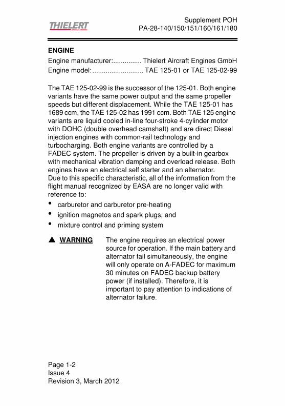
Fuel temperature
Min. fuel temperature limits in the fuel tank:
Table 2-1 Minimum fuel temperature limits in the fuel tank
Oil pressure
Minimum oil pressure:......................................1.2 bar (14.5psi)
Minimum oil pressure (at Take-off power): .....2.3 bar (33.4 psi)
Minimum oil pressure (in flight): ......................2.3 bar (33.4 psi)
Maximum oil pressure:.......................................6.0 bar (87 psi)
Maximum oil pressure (cold start < 20 sec.):....6.5 bar (94.3 psi)
Maximum oil consumption: ..........................0.1 l/h (0.1 quart/h)
Fuel
Minimum permissible fuel
temperature in the fuel
tank before take-off
Minimum permissible fuel
temperature in the fuel
tank during the flight
JET A-1,
JET A,
Fuel No.3,
JP-8,
JP-8+100,
TS-1 (only
C2.0)
-30°C (-22°F) -35°C (-31°F)
Diesel greater than 0° (32°F) -5° (23°F)
� WARNING: The fuel temperature of the fuel tank not
used should be monitored if its later use is
intended.
� WARNING: The following applies to Diesel and JET fuel
mixtures in the tank:
As soon as the proportion of Diesel in the
tank is more than 10% Diesel, the fuel
temperature limits for Diesel operation
must be observed. If there is uncertainty
about which fuel is in the tank, the
assumption should be made that it is
Diesel.
Page 2-3
Issue 4
Revision 3, March 2012

Supplement POH
PA-28-140/150/151/160/161/180
ENGINE INSTRUMENT MARKINGS
The engine data of the TAE 125 installation to be monitored are
integrated in the combined engine instrument CED-125.
The ranges of the individual engine monitoring parameters are
shown in the following table.
Table 2-2 Markings of the engine instruments
Figure 2-1a AED 125 Figure 2-1b CED 125
InstrumentRed
range
Amber
range
Green
range
Amber
range
Red
range
Tachometer [RPM] -------- -------- 0-2300 -------- > 2300
Oil pressure[bar] 0-1.2 1.2-2.3 2.3-5.2 5.2-6.0 > 6.0
[psi] 0-17.4 17.4-33.4 33.4-75.4 75.4-87.0 > 87.0
Coolant
temperatur
[°C] < -32 -32...+60 60-101 101-105 > 105
[°F] < -25.6 -25.6+140 140-214 214-221 > 221
Oil
temperatur
[°C] < -32 -32...+50 50-125 125-140 > 140
[°F] < -25.6 -25.6+122 122+257 257-284 > 284
Gearbox
temperatur
[°C] -------- -------- < 115 115-120 > 120
[°F] -------- -------- < 239 239-248 > 248
Load [%] -------- -------- 0-100 -------- --------
� Note: If an engine reading is in the amber or red
range, the caution light is activated. It only
extinguishes when the "CED/AED-Test/
Confirm" button is pressed.
If this button is pressed longer than a
second, a selftest of the instrument is
initiated.
• • 105
%
RPM
1/ min
bar 6 60 °C
°C
105
50 °C 140 120
100
2300
OP
OT
LOAD
GT
CT2.3
75-3075-30
3022
-5-5
FUEL TEMP RIGHT
°C
FUEL TEMP LEFT
°C
V
VOLT
FUEL
FLOW
gal/h
WATER
LEVEL
60A
AMPERE
Page 2-4
Issue 4
Revision 3, March 2012

Supplement POH
PA-28-140/150/151/160/161/180
WEIGHT LIMITS
PA 28-140 (Normal category):Serial no. 28-20001 to 28-20939:
Maximum Ramp Weight: ..................... 886 kg (1952 lbs)
Maximum Takeoff Weight: ................... 885 kg (1950 lbs)
Maximum Landing Weight ................... 885 kg (1950 lbs)
Serial no. 28-20001 to 28-20939, with Piper Kit 756962 in-
stalled and, Serial no. 28-20940 and up:
Maximum Ramp Weight: ..................... 977 kg (2152 lbs)
Maximum Takeoff Weight: ................... 976 kg (2150 lbs)
Maximum Landing Weight ................... 976 kg (2150 lbs)
PA 28-140 (utility category):
Maximum Ramp Weight: ..................... 886 kg (1953 lbs)
Maximum Takeoff Weight: ................... 885 kg (1950 lbs)
Maximum Landing Weight ................... 885 kg (1950 lbs)
PA 28-150 (normal category):
Maximum Ramp Weight: ..................... 977 kg (2152 lbs)
Maximum Takeoff Weight: ................... 976 kg (2150 lbs)
Maximum Landing Weight ................... 976 kg (2150 lbs)
PA 28-151 (normal category):
Maximum Ramp Weight: .................. 1,056 kg (2327 lbs)
Maximum Takeoff Weight: ................ 1,055 kg (2325 lbs)
Maximum Landing Weight ................ 1,055 kg (2325 lbs)
PA 28-151 (utility category):
Maximum Ramp Weight: ..................... 886 kg (1953 lbs)
Maximum Takeoff Weight: ................... 885 kg (1950 lbs)
Maximum Landing Weight ................... 885 kg (1950 lbs)
Page 2-5
Issue 4
Revision 3, March 2012
Supplement POH
PA-28-140/150/151/160/161/180
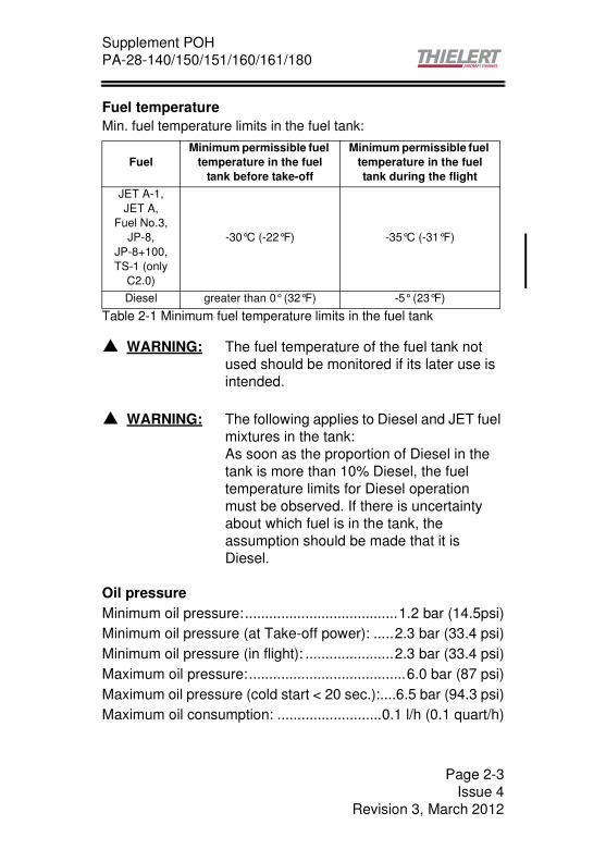
PA 28-160 (normal category, reduced weight):
Maximum Ramp Weight: ..................... 977 kg (2152 lbs)
Maximum Takeoff Weight: ................... 976 kg (2150 lbs)
Maximum Landing Weight ................... 976 kg (2150 lbs)
PA 28-161 (normal category, Warrior III reduced weight):
Maximum Ramp Weight: .................. 1,056 kg (2327 lbs)
Maximum Takeoff Weight: ................ 1,055 kg (2325 lbs)
Maximum Landing Weight ................ 1,055 kg (2325 lbs)
PA 28-161 (utility category):
Maximum Ramp Weight: ..................... 917 kg (2022 lbs)
Maximum Takeoff Weight: ................... 916 kg (2020 lbs)
Maximum Landing Weight ................... 916 kg (2020 lbs)
PA 28-180 (normal category, reduced weight):
Maximum Ramp Weight: ..................... 977 kg (2152 lbs)
Maximum Takeoff Weight: ................... 976 kg (2150 lbs)
Maximum Landing Weight ................... 976 kg (2150 lbs)
PA 28-180 (utility category):
Maximum Ramp Weight: ..................... 886 kg (1953 lbs)
Maximum Takeoff Weight: ................... 885 kg (1950 lbs)
Maximum Landing Weight ................... 885 kg (1950 lbs)
CENTER OF GRAVITY LIMITS
No change, note the maximum weight
Page 2-6
Issue 4
Revision 3, March 2012

Supplement POH
PA-28-140/150/151/160/161/180
MANEUVER LIMITS
Normal Category: No change
Utility Category: Intentionally initiating spins is prohibited
FLIGHT LOAD FACTORS
No change
KINDS OF OPERATION EQUIPMENT LIST
No change
� CAUTION: Intentionally initiating negative G
maneuvers is prohibited!
� Note: The load factor limits for the engine must
also be observed. Refer to the Operation &
Maintenance Manual for the engine.
� CAUTION: Avoid extended negative g-loads duration.
Extended negative g-loads can cause
propeller control and engine problems.
Page 2-7
Issue 4
Revision 3, March 2012
Supplement POH
PA-28-140/150/151/160/161/180
PERMISSIBLE FUEL GRADES
Fuel: .........................................................JET A-1(ASTM 1655)
Alternative: ............................................. JET A (ASTM D 1655)
..........................................Fuel No.3 (GB 6537-2006)
..............................................JP-8 (MIL-DTL-83133E)
......................................JP-8+100 (MIL-DTL-83133E)
................................................... Diesel (DIN EN 590)
Only TAE 125-02-99 (C2.0):
.............................................. TS-1 (GOST 10227-86)
...........................TS-1 (GSTU 320.00149943.011-99)
MAXIMUM FUEL QUANTITIES
Due to the higher specific density of Kerosene and Diesel in
comparison to Aviation Gasoline (AVGAS) with the TAE 125
installation the permissible tank capacity has been reduced
2 standard tanks: ....................................each 85.2 l (22.5 US gal)
Total capacity: ..................................................170.4 l (45 US gal)
Total usable fuel: ..............................................162.8 l (43 US gal)
Total unusable fuel: ................................................7.6 l (2 US gal)
� CAUTION: Using non-approved fuels and additives
can lead to dangerous engine malfunctions.
� CAUTION: To prevent air from penetrating into the fuel
system avoid flying the tanks dry. As soon
as the "Low Level" Warning Light
illuminates, switch to a tank with sufficient
fuel or land.
� Note The tanks are equipped with a Low Fuel
Warning. If the fuel level is below
10 l (2.6 US gal), the "Fuel L" or "Fuel R"
Warning Light illuminates respectively.
Page 2-8
Issue 4
Revision 3, March 2012

Supplement POH
PA-28-140/150/151/160/161/180
PERMISSIBLE OIL TYPES
Engine oil: ......................................... AeroShell Oil Diesel Ultra
...................................... AeroShell Oil Diesel 10W-40
...............................................Shell Helix Ultra 5W-40
...............................................Shell Helix Ultra 5W-30
Gearbox oil:.............................. Shell Spirax S6 GXME 75W-80
.......................................... Shell Spirax S4 G 75W-90
....................... Shell Getriebeöl EP 75W-90 API GL-4
............................................. Shell Spirax EP 75W-90
..................................Shell Spirax GSX 75W-80 GL-4
PERMISSIBLE COOLING LIQUID
Coolant:................Water/Radiator Protection at a ratio of 50:50
Radiator Protection: ............. BASF Glysantin Protect Plus/G48
......................................... Mobil Antifreeze Extra/G48
........................................ESSO Antifreeze Extra/G48
............... Comma Xstream Green - Concentrate/G48
................................................... Zerex Glysantin G48
� CAUTION: Use the approved oil with exact designation
only.
� WARNING The engine must not be started under any
circumstances if any fluid level is too low.
Page 2-9
Issue 4
Revision 3, March 2012

Supplement POH
PA-28-140/150/151/160/161/180
PLACARDS
Near the fuel tank caps:
JET A-1 / Diesel Fuel
CAP. 81.0 LITER (21.5 U.S. GAL.) USABLE
TO BOTTOM OF FILLER INDICATOR TAB
On the oil funnel or at the flap of the engine cowling:
"Oil, see POH supplement"
If installed, at the flap of the engine cowling to the External
Power Receptacle:
„ATTENTION 12 V DC OBSERVE CORRECT POLARITY“
OR
„ATTENTION 24 V DC OBSERVE CORRECT POLARITY“
Page 2-10
Issue 4
Revision 3, March 2012

Supplement POH
PA-28-140/150/151/160/161/180
SECTION 3EMERGENCY PROCEDURES
INDEX OF CHECKLISTSGENERAL........................................................................................3-2
EMERGENCY PROCEDURES CHECK LIST .................................3-2ENGINE FIRE WHEN STARTING ENGINE ON GROUND.............3-2
ENGINE MALFUNCTION
DURING TAKE-OFF (ON GROUND) ..............................................3-2
ENGINE MALFUNCTION IMMEDIATELY
AFTER TAKE-OFF...........................................................................3-3
LOSS OF ENGINE POWER DURING FLIGHT ...............................3-3
EMERGENCY LANDING WITH ENGINE OUT ...............................3-4
ENGINE FIRE IN FLIGHT................................................................3-4
ELECTRICAL FIRE IN FLIGHT .......................................................3-5
LOSS OF OIL PRESSURE..............................................................3-6
LOSS OF FUEL PRESSURE...........................................................3-6
HIGH OIL TEMPERATURE .............................................................3-7
HIGH COOLANT TEMPERATURE..................................................3-7
“Water Level“ LIGHT ILLUMINATES ...............................................3-7
HIGH GEARBOX TEMPERATURE .................................................3-7
ELECTRICAL POWER SUPPLY SYSTEM
MALFUNCTIONS.............................................................................3-8
ALTERNATOR WARNING LIGHT ILLUMINATES DURING NORMAL
ENGINE OPERATION ...................................................................3-10
AMMETER SHOWS BATTERY DISCHARGE DURING
NORMAL ENGINE OPERATION FOR MORE THAN
5 MINUTES....................................................................................3-11
TOTAL ELECTRICAL FAILURE ....................................................3-12
FADEC WARNING LIGHTS ILLUMINATE ....................................3-13
ABNORMAL ENGINE BEHAVIOR.................................................3-15
SPIN RECOVERY..........................................................................3-15
OPEN DOOR .................................................................................3-15
ROUGH ENGINE OPERATION.....................................................3-16
ENGINE MALFUNCTION DURING FLIGHT............................3-16
PROPELLER RPM TOO HIGH ................................................3-16
FLUCTUATIONS IN PROPELLER RPM..................................3-17
ENGINE SHUT DOWN IN FLIGHT................................................3-17
RESTART ATER ENGINE FAILURE.............................................3-18
CARBURETOR ICING...................................................................3-18
FLIGHT IN ICING CONDITIONS ...................................................3-19
Page 3-1
Issue 4
Revision 3, June 2011

Supplement POH
PA-28-140/150/151/160/161/180
GENERAL
In addition to the original AFM/POH, the following applies:
EMERGENCY PROCEDURES CHECK LIST
ENGINE FIRE WHEN STARTING ENGINE ON GROUND
(1) Engine Master - OFF
(2) Fuel Selector - CLOSED
(3) Electrical Fuel Pump - OFF
(4) Switch “Battery“ - OFF
(5) Extinguish the flames with a fire extinguisher, wool blankets
or sand.
(6) Examine the fire damages throughly and repair or replace
the damaged parts before the next flight.
ENGINE MALFUNCTION DURING TAKE-OFF (ON GROUND)
(1) Thrust Lever - IDLE
(2) Brakes - APPLY
(3) Wing flaps (if extended) - RETRACT to increase the
braking effect on the runway.
(4) Engine Master - OFF
(5) Circuit Breaker or Switch “Alternator“, Switches “Main Bus“
and “Battery“ - OFF
� WARNING: Due to an engine shut-off or a FADEC
diagnosed failure there might be a loss
propeller valve currency which leads in a
low pitch setting of the propeller. This might
result in propeller overspeed.
Airspeeds below 100 KIAS/ 115 mph are
suitable to avoid propeller overspeed in
failure case. If the propeller speed control
fails, climb flights can be performed at 65
KIAS/ 75 mph and a powersetting of 100%.
Page 3-2
Issue 4
Revision 3, June 2011

Supplement POH
PA-28-140/150/151/160/161/180
ENGINE MALFUNCTION IMMEDIATELY AFTER TAKE-OFF
- Take-off abort -
If there is an engine malfunction after take-off, at first lower the
nose to keep the airspeed and attain gliding attitude. In most
cases, landing should be executed straight ahead with only
small corrections in direction to avoid obstacles.
(1) Airspeed.............................. 73 KIAS (wing flaps retracted)
............................65 KIAS (wing flaps extended)
(2) Fuel Selector - CLOSED
(3) Engine Master - OFF
(4) Wing flaps - as required (40° is recommended)
(5) Circuit Breaker or Switch "Alternator", Switches "Main Bus"
and "Battery" - OFF
LOSS OF ENGINE POWER DURING FLIGHT
(1) Push Thrust Lever full forward (Take-off position).
(2) Fuel Selector to tank with sufficient fuel quantity and
temperature
(3) Electrical Fuel Pump - ON
(4) Establish Best Glide Speed
(5) Check engine parameters (FADEC lights, oil pressure and
temperature, fuel quantity)
If normal engine performance is not achieved, the pilot should:
i) Land as soon as possible.
ii) Be prepared for an emergency landing
iii) Expect an engine failure.
� WARNING: Altitude and airspeed are seldom sufficient
for a return to the airfield with a 180° turn
while gliding.
� WARNING: The high-pressure pump must be checked
before the next flight.
Page 3-3
Issue 4
Revision 3, June 2011

Supplement POH
PA-28-140/150/151/160/161/180
EMERGENCY LANDING WITH ENGINE OUT
If all attempts to restart the engine fail and an emergency
landing is imminent, select suitable site and proceed as follows:
(1) When field can easily be reached slow down to 63 KIAS for
shortest landing.
(2) Fuel Selector - CLOSED
(3) Engine Master - OFF
(4) Flaps - as required (40° is recommended)
(5) Circuit Breaker or Switch “Alternator“, Switches “Main Bus“
and Battery“ - OFF
(6) Seat belts and harnesses - TIGHT
(7) Touch-down-slightly nose up attitude
(8) Brake firmly
ENGINE FIRE IN FLIGHT
(1) Engine Master - OFF
(2) Fuel Selector - CLOSED
(3) Selector an appropriate airspeed to avoid engine
overspeed
(4) Electrical Fuel Pump - OFF (if in use)
(5) Switch “Main Bus“ - OFF
(6) Cabin heat and defroster - OFF
(7) Perform emergency landing (as described in the procedure
“Emergency Landing With Engine Out“)
� Note: Gliding Distance. Refer to Figure “Glide
range“ in Section 5 of this Supplement to
the Pilot’s Operating Handbook.
Page 3-4
Issue 4
Revision 3, June 2011
Supplement POH
PA-28-140/150/151/160/161/180
ELECTRICAL FIRE IN FLIGHT
The first signs of an electrical fire is usually the odour of burning
or smouldering insulation. Proceed as follows:
(1) Switch “Main Bus“ - OFF
(2) Switch “Avionics“ - OFF
(3) Vents - OPEN
(4) Cabin Heat - OFF
(5) Fire Extinguisher – Activate (if available)
If there is evidence of continued electrical fire, consider turning
off battery and alternator.
(6) Check Circuit Breaker, do not reset if open
(7) Switch “Main Bus“ - ON
(8) Switch “Avionics“ - ON
� WARNING: After the fire extinguisher has been used,
make sure that the fire is extinguished
before exterior air is used to remove smoke
from the cabin.
� WARNING: If the FADEC Backup battery is not installed
this will shut down the engine and require
an emergency landing. The engine has
been demonstrated to continue operating
for a maximum of 30 minutes when
powered by the FADEC Backup battery
only.
� WARNING: Turn on only electrical equipment required
to continue flight depending on the situation
and land as soon as practical.
Do only switch ON one at a time, with delay
after each.
Page 3-5
Issue 4
Revision 3, June 2011

Supplement POH
PA-28-140/150/151/160/161/180
LOSS OF OIL PRESSURE (<2.3 bar IN CRUISE (amber range) OR <1.2 bar AT IDLE (red range))
(1) Reduce power as quickly as possible
(2) Check oil temperature: If the oil temperature is high or near
operating limits,
i) Land as soon as possible.
ii) Be prepared for an emergency landing.
iii) Expect an engine failure.
(1) Increase airspeed by decreasing the pitch angle
(2) Reduce power, if the engine temperatures approach the
red area
LOSS OF FUEL PRESSURE
Not applicable for TAE 125 installation
� Note: During warm-weather operation or longer
climbouts at low airspeed engine
temperatures could rise into the amber
range and trigger the caution light. This
warning allows the pilot to avoid
overheating of the engine as follows:
Page 3-6
Issue 4
Revision 3, June 2011

Supplement POH
PA-28-140/150/151/160/161/180
HIGH OIL TEMPERATURE (“OT“ in red range)
(1) Increase airspeed and reduce power as quickly as possible
(2) Check the oil pressure: if the oil pressure is lower than normal
(<2.3 bar at cruise or <1.2 bar at idle),
i) Land as soon as possible.
ii) Be prepared for an emergency landing.
iii) Expect an engine failure.
(3) If the oil pressure is in normal range:
i) Land as soon as practical.
HIGH COOLANT TEMPERATURE (“CT“ in red range)
(1) Increase airspeed and reduce power as quickly as possible(2) Cabin Heat and Shut Off Cabin Heat - COLD, resp. CLOSED
(3) If this reduces the coolant temperature to within the normal
operating range quickly, continue to fly normally and
observe coolant temperature, Cabin Heat as required
(4) As far as this does not cause the coolant temperature to drop
i) Land as soon as practical.
ii) Be prepared for an emergency landing.
iii) Expect an engine failure.
“Water Level“ LIGHT ILLUMINATES
(1) Increase airspeed and reduce power as quickly as possible
(2) Coolant temperature “CT“ - CHECK and OBSERVE
(3) Oil temperature “OT“ - CHECK and OBSERVE
(4) As far as coolant temperature and/or oil temperature are
rising into amber or red range,
i) Land as soon as practical.
ii) Be prepared for an emergency landing.
iii) Expect an engine failure.
HIGH GEARBOX TEMPERATURE (“GT“ in red range)
(1) Reduce power to 55% - 75% as quickly as possible
(2) Land as soon as practical
Page 3-7
Issue 4
Revision 3, June 2011

Supplement POH
PA-28-140/150/151/160/161/180
ELECTRICAL POWER SUPPLY SYSTEM MALFUNCTIONS
(continued next page)
� CAUTION: The TAE 125 requires an electrical power
source for its operation. If the alternator
fails, continued engine operation time is
dependant upon the remaining capacity of
the main batter, the FADEC backup battery
(if installed) and equipment powered. The
engine has been demonstrated to continue
operating for approximately 120 minutes
based upon the following assumptions:
Equipment Time switched on
in [min] in [%]
NAV/COM 1 receiving ON 120 100
NAV/COM 1 transmitting ON 12 10
NAV/COM 2 receiving OFF 0 0
NAV/COM 2 transmitting OFF 0 0
GPS ON 60 50
Transponder ON 120 100
Fuel Pump OFF 0 0
AED-125 ON 120 100
Battery Ignition Relay ON 120 100
CED-125 ON 120 100
Landing Light ON 12 10
Flood Light ON 1.2 1.0
Pilot Heat ON 24 20
Wing Flaps ON 1.2 1.0
Interior Lightning OFF 0 0
Navigation Lights OFF 0 0
Beacon Lights OFF 0 0
Strobe Lights OFF 0 0
ADF OFF 0 0
Intercom OFF 0 0
Turn Indicator OFF 0 0
Engine control system ON 120 100
Page 3-8
Issue 4
Revision 3, June 2011

Supplement POH
PA-28-140/150/151/160/161/180
� CAUTION: This table only gives a reference point. The
pilot should turn off all nonessential items
and supply power only to equipment which
is absolutely necessary for continued flight
depending upon the situation.
If deviated from this recommendation, the
remaining engine operating time may
change.
� WARNING: If the power supply from both alternator and
main battery is interrupted, continued
engine operation is dependant on the
remaining capacity of the FADEC backup
battery (if installed). The engine has been
demonstrated to continue operating for 30
minutes when powered by the FADEC
backup battery only. In this case, all
electrical equipment will not operate:
- land immidiately
- do not switch the „FORCE-B“ switch, this
will shut down the engine
Page 3-9
Issue 4
Revision 3, June 2011

Supplement POH
PA-28-140/150/151/160/161/180
ALTERNATOR WARNING LIGHT ILLUMINATES DURING NORMAL ENGINE OPERATION
(1) Ammeter - CHECK
(2) Circuit Breaker or Switch “Alternator“ CHECK - ON
(3) Battery Switch CHECK - ON
(4) Electrical load - REDUCE IMMEDIATELY depending upon
operation as follows:
i) NAV/ COM 2 – OFF
ii) Fuel Pump – OFF
iii) Landing Light – OFF (use as required for
landing)
iv) Taxi Light – OFF
v) Strobe Light – OFF
vi) Nav Lights – OFF
vii) Beacon – OFF
viii)Interior Lights – OFF
ix) Intercom – OFF
x) Pitot Heat – OFF (use as required)
xi) Autopilot – OFF
xii) Non-essential equipment – OFF
(5) The pilot should
i) Land as soon as practical.
ii) Be prepared for an emergency landing.
iii) Expect an engine failure.
� CAUTION: If the FADEC was supplied by battery only
until this point, the RPM can momentarily
drop, when the alternator will be switched
on. In any case: leave the alternator
switched ON!
Page 3-10
Issue 4
Revision 3, June 2011

Supplement POH
PA-28-140/150/151/160/161/180
AMMETER SHOWS BATTERY DISCHARGE DURING NORMAL ENGINE OPERATION FOR MORE THAN 5 MINUTES
(1) Circuit Breaker or Switch “Alternator“ CHECK - ON
(2) Battery Switch CHECK - ON
(3) Electrical load - REDUCE IMMEDIATELYdepending upon
operation as follows:
i) NAV/ COM 2 – OFF
ii) Fuel Pump – OFF
iii) Landing Light – OFF (use as required for
landing)
iv) Taxi Light – OFF
v) Strobe Light – OFF
vi) Nav Lights – OFF
vii) Beacon – OFF
viii)Interior Lights – OFF
ix) Intercom – OFF
x) Pitot Heat – OFF (use as required)
xi) Autopilot – OFF
xii) Non-essential equipment – OFF
(4) The pilot should,
i) Land as soon as practical.
ii) Be prepared for an emergency landing.
iii) Expect an engine failure.
� Note: When the AED Ammeter indication is
illuminated at the outer left side and the
voltage indication is decreasing
simultaneously, the battery is being
discharged.
� CAUTION: If the FADEC was supplied by battery only
until this point, the RPM can momentarily
drop, when the alternator will be switched on.
In any case: leave the alternator switched ON!
Page 3-11
Issue 4
Revision 3, June 2011

Supplement POH
PA-28-140/150/151/160/161/180
TOTAL ELECTRICAL FAILURE
(all equipment inoperative, except engine)
(1) Circuit Breaker or Switch “Alternator” CHECK – ON
(2) Battery Switch CHECK – ON
(3) Land as soon as possible
i) Be prepared for an emergency landing
ii) Expect an engine failure
� WARNING: If the power supply from both alternator and
main battery is interrupted simultaneously,
continued engine operation is dependant
on the remaining capacity of the FADEC
backup battery. The engine has been
demonstrated to continue operating for 30
minutes when powered by the FADEC
backup battery only. In this case, all other
electrical equipment will not operate.
� WARNING: If the aircraft was operated on battery
power only until this point (alternator
warning light illuminated), the remaining
engine operating time may be less than 30
minutes.
� WARNING: Do not active the FORCE-B switch, this will
shut down the engine.
Page 3-12
Issue 4
Revision 3, June 2011

Supplement POH
PA-28-140/150/151/160/161/180
FADEC WARNING LIGHTS ILLUMINATE
One FADEC Light is flashing
(1) Press FADEC-Testknob at least 2 seconds
(2) FADEC Light extinguished (LOW category warning):
a) Continue flight normally
b) Inform service center after landing
(3) FADEC Light steady illuminated (HIGH category warning):
a) Observe the other FADEC light
b) Land as soon as practical
c) Select an airspeed to avoid engine overspeed
d) Inform service center after landing
(continued next page)
� Note: The FADEC consists of two components
that are independent of each other:
FADEC A and FADEC B. In case of
malfunctions in the active FADEC, it
automatically switches to the other.
Page 3-13
Issue 4
Revision 3, June 2011
Supplement POH
PA-28-140/150/151/160/161/180
Both FADEC Lights are flashing
(1) Press FADEC-Testknob at least 2 seconds
(2) FADEC Light extinguished (LOW category warning):
a) Continue flight normally
b) Inform service center after landing
(3) FADEC Light steady illuminated (HIGH category warning):
a) Check the available engine power
b) Expect engine failure
c) Flight can be continued, however the pilot should:
i) Select an appropriate airspeed to avoid engine
overspeed.
ii) Land as soon as possible.
iii) Be prepared for an emergency landing.
d) Inform service center after landing.
(4) In case a tank was flown dry, proceed at the first signs of
insufficient fuel feed as follows:
a) Immediately switch the Fuel Selector to tank with
sufficient fuel quantity.
b) Electrical Fuel Pump - ON
c) Select an appropriate airspeed to avoid engine
overspeed.
d) Check the engine (engine parameters, airspeed /
altitude change, whether the engine responds to
changes in the Thrust Lever position).
e) If the engine acts normally, continue the flight and land
as soon as practical.
� Note: The load display may not correspond to the
actual value.
� WARNING: The high-pressure pump must be checked
before the next flight
Page 3-14
Issue 4
Revision 3, June 2011

Supplement POH
PA-28-140/150/151/160/161/180
ABNORMAL ENGINE BEHAVIOR
If the engine acts abnormally during flight and the system does
not automatically switch to the B-FADEC, it is possible to switch
to the B-FADEC manually.
(1) Select an appropriate airspeed to avoid engine overspeed
(2) "Force B" switch - SELECT manually to B-FADEC
(3) Flight may be continued, but the pilot should:
i) Select an appropriate airspeed to avoid engine
overspeed.
ii) Land as soon as practical
iii) Be prepared for an emergency landing
SPIN RECOVERY
No change for the TAE 125 installation
OPEN DOOR
No change for the TAE 125 installation
� WARNING: It is only possible to switch from the
automatic position to B-FADEC (A-FADEC
is active in normal operation, B-FADEC is
active in case of malfunction). This only
becomes necessary when no automatic
switching occurred in case of abnormal
engine behavior.
� WARNING: When opearting on FADEC backup battery
only, the "Force B" switch must not be
activated. This will shutdown the engine.
Page 3-15
Issue 4
Revision 3, June 2011

Supplement POH
PA-28-140/150/151/160/161/180
ROUGH ENGINE OPERATION
ENGINE MALFUNCTION DURING FLIGHT
In case that one tank was flown dry, at the first signs of
insufficient fuel feed proceed as follows:
(1) Immediately switch the Fuel Selector to tank with sufficient
fuel quantity
(2) Electrical Fuel Pump - ON
(3) Check the engine (engine parameters, airspeed/altitude
change, whether the engine responds to changes in the
Thrust Lever position)
(4) If the engine acts normally, continue the flight and land as
soon as practical.
PROPELLER RPM TOO HIGH
with propeller RPM between 2,300 and 2,400 for more than 20
seconds or over 2,400:
(1) Reduce power
(2) Reduce airspeed below 100 KIAS or as appropriate to
prevent propeller overspeed
(3) Set power as required to maintain altitude and land as soon
as practical.
� Note: Flying a tank dry activates both FADEC
lights flashing.
� WARNING: The high-pressure pump must be checked
before the next flight.
� Note: If the propeller speed control fails, climb
flights can be performed at 65 KIAS/ 75
mph and a power setting of 100%. In case
of overspeed the FADEC will reduce the
engine power at higher airspeeds to avoid
propeller speeds above 2500 rpm
Page 3-16
Issue 4
Revision 3, June 2011

Supplement POH
PA-28-140/150/151/160/161/180
FLUCTUATIONS IN PROPELLER RPM
If the propeller RPM fluctuates by more than +/- 100 RPM with
a constant Thrust Lever position:
(1) Change the power setting and attempt to find a setting
where the propeller RPM no longer fluctuates
(2) If this does not work, set the maximum power at an
airspeed <100 KIAS until the propeller speed stabilizes
(3) If the problem is resolved, continue the flight
(4) If the problem continues, reduce power to 55% - 75& or
select a power level where the propeller RPM fluctuations
are minimum. Fly at an airspeed below 110 KIAS and land
as soon as practical
ENGINE SHUT DOWN IN FLIGHT
If it is necessary to shut down the engine in flight (for instance,
abnormal engine behavior does not allow continued flight or
there is a fuel leak, etc.), proceed as follows:
(1) Select an appropriate airspeed to avoid engine overspeed
(2) Engine Master - OFF
(3) Fuel Selector - CLOSED
(4) Electrical Fuel Pump - OFF (if in use).
(5) If the propeller also has to be stopped (for instance, due to
excessive vibrations)
i) Reduce airspeed to below 55 KIAS.
ii) when the propeller is stopped, continue to glide
at 73 KIAS.
Page 3-17
Issue 4
Revision 3, June 2011

Supplement POH
PA-28-140/150/151/160/161/180
RESTART AFTER ENGINE FAILURE
Whilst gliding to a suitable landing strip, try to determine the
reason for the engine malfunction. If time permits and a restart
of the engine is possible, proceed as follows:
(1) Airspeed between 65 and 85 KIAS (maximal 100 KIAS)
(2) Glide below 13000 ft
(3) Fuel Selector to tank with sufficient fuel quantity and
temperature
(4) Electrical Fuel Pump - ON
(5) Thrust Lever - IDLE
(6) Engine Master OFF, than ON (if the propeller does not turn,
then additionally “Starter“ ON)
(7) Check the engine power: Thrust Lever 100%, engine
parameters, check altitude and airspeed
CARBURETOR ICING
Not applicable for the TAE installation.
� Note: The propeller will normally continue to turn
as long as the airspeed is above 65 KIAS.
Should the propeller stop at an airspeed of
65 KIAS or more, the reason for this should
be found out before attempting a restart.
If it is obvious that the engine or propeller is
jammed, do not use the starter
� Note: If the Engine Master is in position OFF, the
load display shows 0% even if the propeller
is turning.
Page 3-18
Issue 4
Revision 3, June 2011

Supplement POH
PA-28-140/150/151/160/161/180
FLIGHT IN ICING CONDITIONS
In case of inadvertent icing encounter proceed as follows:
(1) Pitot Heat switch - ON (if installed)
(2) Turn back or change the altitude to obtain an outside air
temperature that is less conducive to icing.
(3) Cabin heat control full and open defroster outlets to obtain
maximum windshield defroster airflow. Adjust cabin air
control to get maximum defroster heat and airflow.
(4) Advance the Thrust Lever to increase the propeller speed
and keep ice accumulation on the propeller blades as low
as possible.
(5) Watch for signs of air filter icing and pull the "Alternate Air
Door" control if necessary. An unexplained loss in engine
power could be caused by ice blocking the air intake filter.
Opening the "Alternate Air Door" allows preheated air from
the engine compartment to be aspirated.
(6) Plan a landing at the nearest airfield. With an extremely
rapid ice build up, select a suitable "off airfield" landing side.
(7) With an ice accumulation of 0.5 cm or more on the wing
leading edges, a significantly higher stall speed should be
expected.
(8) Leave wing flaps retracted. With a severe ice build up on
the horizontal tail, the change in wing wake airflow direction
caused by wing flap extension could result in a loss of
elevator effectiveness.
(9) Open left window, if practical, scrape ice from a portion of
the windshield for visibility in the landing approach.
(10) Perform a landing approach using a forward slip, if
necessary, for improved visibility.
(11) Approach at increased airspeed depending upon the
amount of the accumulation.
(12) Perform a landing in level attitude.
� WARNING: Flight into known icing conditions is prohibited.
Page 3-19
Issue 4
Revision 3, June 2011

Supplement POH
PA-28-140/150/151/160/161/180
This page is intentionally left blank
Page 3-20
Issue 4
Revision 3, June 2011

Supplement POH
PA-28-140/150/151/160/161/180
SECTION 4NORMAL PROCEDURES
PREFLIGHT INSPECTION
PREPARATION
Airplane status ................................ airworthy, papers on board
Logbook ....CHECK refuelling with allowed fuel (see section 2)
Weather ........................................................................suitable
Baggage ................................................. weighed, stowed, tied
Weight and CG ........................................................within limits
Navigation ..................................................................... planned
Charts and navigation equipment ................................on board
Performance and range .............................. computed and safe
Page 4-1
Issue 4
Revision 2, March 2012

Supplement POH
PA-28-140/150/151/160/161/180
COCKPIT
Control wheel .........................................................release belts
Avionics...............................................................................OFF
Parking brake ..................................................................... SET
Electric switches .................................................................OFF
Engine Master switch..........................................................OFF
Shut-off Cabin Heat .........................................................OPEN
Switches "Battery" and "Main Bus“ .......................................ON
Fuel quantity gauges..................................................... CHECK
Fuel Temperature ......................................................... CHECK
"Water level" Light on AED ........................... CHECK, that OFF
Annunciator panel ......................................................... CHECK
Switches "Battery" and "Main Bus“ .....................................OFF
Flight Controls............................................................... CHECK
Flaps ............................................................................. CHECK
Trim.......................................................CHECK, set NEUTRAL
Pitot drain..........................................................DRAIN, CLOSE
Static drain ........................................................DRAIN, CLOSE
Windows ......................................................... CHECK, CLEAN
Tow bar ........................................................................... STOW
Baggage......................................................................SECURE
Baggage door ...............................................CLOSE, SECURE
� WARNING: When turning on the battery switch, using
an external power source, or pulling the
propeller through by hand, treat the
propeller as if the Engine Master was ON.
Page 4-2
Issue 4
Revision 2, March 2012
Supplement POH
PA-28-140/150/151/160/161/180
RIGHT WING
Wing........................................................ free of ice, snow, frost
Control surfaces................................... CHECK for interference
................................................................ free of ice, snow, frost
Hinges.................................................. CHECK for interference
Static wicks ................................................................... CHECK
Wing tip and lights......................................................... CHECK
Fuel tank .............................................. CHECK supply visually,
........................ fuel level not above bottom of filler indicator tab
................................................................................secure caps
Fuel tank sump ................................. DRAIN, CHECK for water
...................................sediment and proper fuel (see section 2)
Fuel vent ........................................................................ CLEAR
Tie down and chock ................................................... REMOVE
Main gear strut ............. Proper Inflation (114 ± 6 mm / 4.50 in.)
Tire................................................................................ CHECK
Brake block and discs ................................................... CHECK
Fresh air inlet ................................................................. CLEAR
NOSE
Oil..........................................................................CHECK level
Oil dipstick...................................................................SECURE
Fuel and oil .....................................................CHECK for leaks
Cowling .......................................................................SECURE
Windshield .................................................................... CHECK
Propeller and spinner.................................................... CHECK
Air inlets ..........................................UNDAMAGED and CLEAR
Landing light.................................................................. CHECK
Gearbox oil............................................................ CHECK level
Nose chock ................................................................ REMOVE
Nose gear strut .............. Proper Inflation (83 ± 6 mm / 3.25 in.)
Nose wheel tire ............................................................. CHECK
Fuel strainer ....................................................................DRAIN
....... CHECK for watersediment and proper fuel (see section 2)
Page 4-3
Issue 4
Revision 2, March 2012

Supplement POH
PA-28-140/150/151/160/161/180
LEFT WING
Wing........................................................ free of ice, snow, frost
Fresh air inlet ................................................................. CLEAR
Main gear strut ............. Proper Inflation (114 ± 6 mm / 4.50 in.)
Tire................................................................................ CHECK
Brake block and discs ................................................... CHECK
Fuel tank .............................................. CHECK supply visually,
........................ fuel level not above bottom of filler indicator tab
................................................................................secure caps
Fuel tank sump ................................ DRAIN, CHECK for water,
...................................sediment and proper fuel (see section 2)
Fuel vent ........................................................................ CLEAR
Tie down and chock ................................................... REMOVE
Pitot heat..................................REMOVE cover - holes CLEAR
Wing tip and lights......................................................... CHECK
Control surfaces.................................. CHECK for interference-
................................................................ free of ice, snow, frost
Hinges.................................................. CHECK for interference
Static wicks ................................................................... CHECK
FUSELAGE
Antennas....................................................................... CHECK
Empennage............................................. free of ice, snow, frost
Fresh air inlet ................................................................. CLEAR
Stabilator and trim tab.......................... CHECK for interference
Tie down .................................................................... REMOVE
Battery switch........................................................................ON
Check lighting ............................................................... CHECK
Nav and strobe lights .................................................... CHECK
Stall warning ................................................................. CHECK
Pitot heat....................................................................... CHECK
All switches .........................................................................OFF
Passengers .......................................................................board
Page 4-4
Issue 4
Revision 2, March 2012
Supplement POH
PA-28-140/150/151/160/161/180
Cabin door ..............................................CLOSE and SECURE
Seat belts and harnesses .......... FASTEN - CHECK inertia reel
BEFORE STARTING ENGINE
Brakes.................................................................................SET
Fuel Selector.......................................................... desired tank
Radios.................................................................................OFF
Alternate Air Door ....................................................... CLOSED
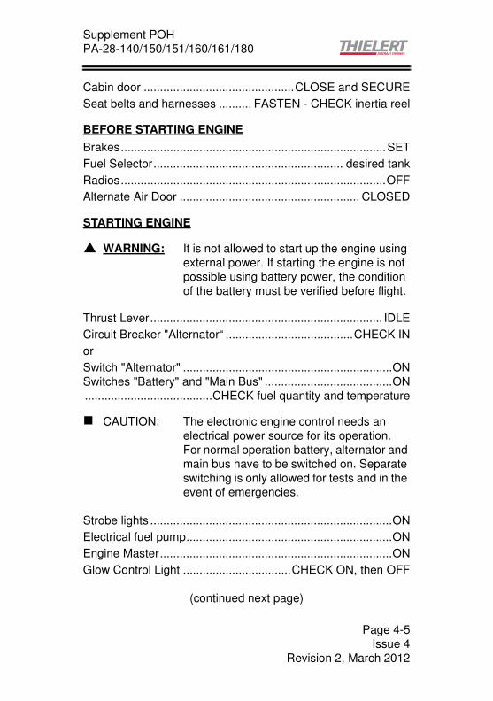
STARTING ENGINE
Thrust Lever....................................................................... IDLE
Circuit Breaker "Alternator“ .......................................CHECK IN
or
Switch "Alternator" ................................................................ON
Switches "Battery" and "Main Bus" .......................................ON
.......................................CHECK fuel quantity and temperature
Strobe lights ..........................................................................ON
Electrical fuel pump...............................................................ON
Engine Master.......................................................................ON
Glow Control Light .................................CHECK ON, then OFF
(continued next page)
� WARNING: It is not allowed to start up the engine using
external power. If starting the engine is not
possible using battery power, the condition
of the battery must be verified before flight.
� CAUTION: The electronic engine control needs an
electrical power source for its operation.
For normal operation battery, alternator and
main bus have to be switched on. Separate
switching is only allowed for tests and in the
event of emergencies.
Page 4-5
Issue 4
Revision 2, March 2012

Supplement POH
PA-28-140/150/151/160/161/180
Starter ........................................... ENGAGE until engine starts
Oil pressure................................................................... CHECK
CED/AED Test Button............ PRESS (to delete Caution Light)
Ammeter .......................... CHECK for positive charging current
Voltmeter.......................................... CHECK for GREEN range
FADEC Backup Battery Test (if installed)
a) Alternator ............ OFF, engine must operate normally
b) Battery ............................... OFF, for min. 10 seconds;
engine must operate normally, the red FADEC lamps
must not be illuminated
c) Battery ....................................................................ON
d) Alternator ................................................................ON
Avionics.................................................................................ON
Ammeter ............................ Check for positive charging current
Voltmeter................................................ Check for green range
STARTING ENGINE WHEN COLD.....................................N/ASTARTING ENGINE WHEN HOT .......................................N/ASTARTING ENGINE WHEN FLOODED .............................N/AGROUND CHECK ...............................................................N/A
� CAUTION: Shut down the engine immediately if the
minimum oil pressure of 1 bar is not
indicated after 3 seconds!
� WARNING It must be ensured that both battery and
alternator are ON!
If the guarded alternator switch is installed,
the switch guard must be closed.
Page 4-6
Issue 4
Revision 2, March 2012

Supplement POH
PA-28-140/150/151/160/161/180
WARM UP
Let the engine warm up for about 2 minutes at 890 RPM.
Increase RPM to 1400 until Oil temperature 50°C, Coolant
temperature 60°C.
FADEC AND PROPELLER ADJUSTMENT FUNCTION CHECK
a) Thrust Lever - IDLE, both FADEC lights should be OFF
b) FADEC Test Button - PRESS and HOLD for entire test
c) Both FADEC lights - ON, RPM increases
d) The FADEC automatically switches to B-component
(only FADEC B light is ON)
e) The propeller control is excited; RPM decreases
f) The FADEC automatically switches to A-component
(only FADEC A light is ON), RPM increases
g) The propeller control is excited; RPM decreases
h) FADEC A light goes OFF, idle RPM is reached, the test
is completed
i) FADEC Test Button - RELEASE
� WARNING: If the FADEC lights do not come on at this
point, it means that the test procedure has
failed and take-off should not be attempted.
� WARNING: If there are prolonged engine misfires or the
engine shuts down during the test, take off
may not be attempted.
� WARNING: The whole test procedure has to be
performed without any failure. In case the
engine shuts down or the FADEC lights are
flashing, take-off is prohibited. This applies
even if the engine seems to run without
failure after the test.
Page 4-7
Issue 4
Revision 2, March 2012

Supplement POH
PA-28-140/150/151/160/161/180
Thrust Lever .................................................FULL FORWARD,
.................................. load display min. 94%, RPM 2240 - 2300
Thrust Lever....................................................................... IDLE
BEFORE TAKE-OFF
Circuit Breaker or Switch "Alternator", Switches "Battery" and
"Main Bus“...............................................................CHECK ON
Flight instruments.......................................................... CHECK
Alternator Warning Light ....................................................OFF
Fuel Selector............................................................proper tank
Fuel Temperature ......................................................... CHECK
Electrical Fuel Pump ............................................................ON
Engine Instruments ....................................................... CHECK
Alternate Air Door ....................................................... CLOSED
Seat backs .....................................................................ERECT
Belts / harness ........................................ FASTENED / CHECK
Empty seats. ............................... seat belts snugly FASTENED
Flaps ................................................................................... SET
Trim tab............................................................................... SET
Controls............................................................................ FREE
Door ............................................................................... LATCH
� Note: If the Test Button is released before the
self-test is over, the FADEC immediately
switches over to normal operation.
� Note: While switching from one FADEC to
another, it is normal to hear and feel a
momentary surge in the engine.
Page 4-8
Issue 4
Revision 2, March 2012

Supplement POH
PA-28-140/150/151/160/161/180
TAKE-OFF
Normal take-off - PA 28-140/-150/-160/-180
Flaps ..................................................................10° (first notch)
Trim..................................................................................... SET
Accelerate to 57 KIAS
Control wheel .............. back pressure to rotate to climb attitude
Accelerate to and maintain 65 KIAS until obstacle clearance is
achieved.
Best rate climb speed (flaps 10°) ..................................70 KIAS
Flaps .............................................................. RETRACT slowly
Normal take-off - PA 28-151/161
Flaps ..................................................................10° (first notch)
Trim..................................................................................... SET
Accelerate to 50 KIAS
Control wheel .............. back pressure to rotate to climb attitude
Accelerate to and maintain 55 KIAS until obstacle clearance is
achieved.
Best rate climb speed (flaps 10°) ..................................65 KIAS
Flaps .............................................................. RETRACT slowly
� Note: For better engine cooling a climb speed of
79 KIAS is recommended.
� Note: For better engine cooling a climb speed of
79 KIAS is recommended.
Page 4-9
Issue 4
Revision 2, March 2012

Supplement POH
PA-28-140/150/151/160/161/180
CLIMB
Best rate climb speed (flaps up)
PA 28-140/150/160/180.........................................75 KIAS
PA 28-151/161.......................................................70 KIAS
En route ........................................................................87 KIAS
Electrical Fuel Pump ............................. OFF at desired altitude
CRUISING
Cruise Power ...................................................................... SET
.............................. (max. 100%, 75% or less is recommended)
CED 125, AED 125 and Caution Light...................... MONITOR
............. (oil pressure, water level as well as temperature of oil,
.........................water, gearbox and fuel within operating limits)
Fuel quantity ............................................................. MONITOR
(Gauges and LOW LEVEL caution lights)
Select the other fuel tank approximately every 30 minutes to
empty and heat both tanks equally (observe Section 2
"Operating Limits" Chapter "Engine Operating Limits").
FADEC Warning Lights............................................. MONITOR
DESCENT
Normal
Thrust Lever...................................................... AS REQUIRED
Airspeed...................................................... NOT EXCEED VNO
� Note: For better engine cooling a climb speed of
79 KIAS is recommended.
� CAUTION: Do not use any fuel tank below the
minimum permissible fuel temperature!
Page 4-10
Issue 4
Revision 2, March 2012
Supplement POH
PA-28-140/150/151/160/161/180
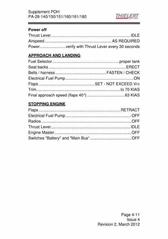
Power off
Thrust Lever....................................................................... IDLE
Airspeed............................................................ AS REQUIRED
Power.......................verify with Thrust Lever every 30 seconds
APPROACH AND LANDING
Fuel Selector............................................................proper tank
Seat backs .....................................................................ERECT
Belts / harness ............................................. FASTEN / CHECK
Electrical Fuel Pump .............................................................ON
Flaps ..................................................SET - NOT EXCEED VFE
Trim........................................................................... to 70 KIAS
Final approach speed (flaps 40°) ..................................63 KIAS
STOPPING ENGINE
Flaps ......................................................................... RETRACT
Electrical Fuel Pump ...........................................................OFF
Radios.................................................................................OFF
Thrust Lever....................................................................... IDLE
Engine Master.....................................................................OFF
Switches "Battery" and "Main Bus“ .....................................OFF
Page 4-11
Issue 4
Revision 2, March 2012

Supplement POH
PA-28-140/150/151/160/161/180
This page is intentionally left blank
Page 4-12
Issue 4
Revision 2, March 2012

Supplement POH
PA-28-140/150/151/160/161/180
SECTION 5PERFORMANCE
FLIGHT PLANNING EXAMPLE
a) Airplane Loading
The first step in planning a flight is to calculate the airplane
weight and center of gravity by utilizing the information provided
by Section 6 (Weight and Balance) of this supplement to the
Pilot’s Operating Handbook.
The Basic Empty Weight of the airplane, determined by the
company who made the modification, has been entered in
Figure 6-5a of this supplement. If any alterations to airplane
have been made affecting weight and balance, reference to the
aircraft logbook and Weight and Balance Record (Figure 6-7)
should be made to determine the current Basic Empty Weight of
the airplane.
Make use of the Weight and Balance Loading Form (Figure 6-
11a) of this supplement and the C.G. Range and Weight graph
of the EASA approved Pilot's Operating Handbook approved to
determine the total weight of the airplane and the center of
gravity position.
� Note: The information contained in this Section is
to be used for example purposes only. The
maximum weights according to section 2
are to be observed for flight planning.
This example is based on a PA 28-161 -
Normal category;
Max. Ramp Weight 1056 kg (2327 lbs),
Max. Take-Off Weight 1055 kg (2325 lbs)
Page 5-1
Issue 4
Revision 2, Juni 2011

Supplement POH
PA-28-140/150/151/160/161/180
After proper utilization of the information provided, the following
weights apply to the flight planning example:
The landing weight cannot be determined until the weight of fuel
to be used has been established (refer to item (g)(1)).
(1) Basic Empty Weight ............................... 730 kg (1609 lbs)
(2) Occupants (2 x 77 kg/ 170 lbs)................. 154 kg (340 lbs)
(3) Baggage and cargo ...................................... 24 kg (51 lbs)
(4) Fuel (0.84 kg/l x 170 l, 7 lb/gal x 45 US gal, JET A-1)
.................................................................. 142 kg (315 lbs)
(5) Take-off Weight ................................... 1,050 kg (2315 lbs)
(6) Landing Weight
(a) (5) minus (g) (1)
(1050 kg minus 51.6 kg)............................... 998.4 kg
(2317 lbs minus 113.4 lbs) .........................2201.6 lbs
The take-off weight is below the maximum of 1055 kg (2325
lbs), and the weight and balance calculations have determined
that the C.G. position is within the approved limits.
(b) Take-off and landing
Now that the aircraft loading has been determined, all aspects
of the take-off and landing must be considered.
All of the existing conditions at the departure and destination
airport must be acquired, evaluated and maintained throughout
the flight.
Apply the departure airport conditions and take-off weight to the
appropriate take-off performance figures (Figure 5-1) to
determine the length of runway necessary for the take-off and/
or the barrier distance.
The landing distance calculations are performed in the same
manner using the existing conditions at the destination airport
and, when established, the landing weight.
Page 5-2
Issue 4
Revision 2, Juni 2011

Supplement POH
PA-28-140/150/151/160/161/180
The conditions and calculations for the example flight are listed
below. The take-off and landing distances required for the
example flight have fallen well below the available runway
lengths.
Departure Airport Destination Airport
(1) Pressure Altitude 1,500ft 2,500 ft
(2) Temperature 27°C (ISA + 15°C) 24°C (ISA + 14°C)
81°F (ISA + 27°F) 75°F (ISA + 25°F)
(3) Wind Component 0 knots 0 knots
(4) Runway Length Available 1,463 m 2,316 m
The takeoff distance chart, Figure 5-1 (Takeoff Distance),
should be consulted, keeping in mind that distances shown are
based on the short field technique. Conservative distances can
be established by reading the chart at the next higher value of
weight, temperature and altitude. For example, in this particular
sample problem, the takeoff distance information presented for
a weight of 1,055 kg, pressure altitude of 2000 ft and a
temperature of ISA+20°C/ +36°F should be used and results in
the following:
Ground Roll 424 m (1391ft)
Total Distance to clear a 15 m obstacle 714 m (2343ft)
For calculation of landing distance refer to original POH
� Note: The remainder or the performance charts
used in this flight planning example assume
no wind condition. The effect of winds aloft
must be considered by the pilot when
computing climb, cruise and descent
performance.
Page 5-3
Issue 4
Revision 2, Juni 2011

Supplement POH
PA-28-140/150/151/160/161/180
(c) Climb
The next step in the flight plan is to determine the necessary
climb segment components.
The desired cruise pressure altitude and corresponding cruise
outside air temperature values are the first variables to be
considered in determining the climb components from the table
"Time, Fuel and Distance to Climb" (Tab. 5-3). After time,
distance and quantity of fuel for the cruise pressure altitude and
outside air temperature values have been established, apply the
existing conditions at the departure field to Tab. 5-3. Now,
subtract the values obtained from the table for the field of
departure conditions from those for the cruise pressure
altitude.The remaining values are the true fuel, time and
distance components for the climb segment of the flight plan
corrected for field pressure altitude and temperature.
The following values were determined from the above
instructions in the flight planning example:
(1) Cruise Pressure Altitude.................................. 5,000 ft
(2) Cruise OAT...... 16°C (ISA + 11°C)/ 61°F (ISA + 20°F)
Due to the difference in temperature to the standard
atmosphere, the following correction applies:
(3) Time to Climb
(8.4 min minus 1.6 min = 6.8) + 11%) ............. 7.5 min
(4) Distance to Climb
((10.4 NM minus 1.9 NM = 8.5) + 11%)............9.4 NM
(5) Fuel to Climb
((4.3 l minus 0.8 l Jet A-1 = 3.5 l) + 11%)............. 3.9 l
((1.1 minus 0.2 US gal = 0.9 US gal) + 11%) 1 US gal
(6) Fuel to start-up, taxi and take-off............1l/ 0.3 US gal
(7) Fuel for start-up, taxi and take-off and climb
(1 l plus 3.9 l) ........................................................ 4.9 l
(0.3 US gal plus 1 US gal) .......................... 1.3 US gal
11°C 20°F( )
10°C 18°F( )--------------------------------x10% 11% Increase=
Page 5-4
Issue 4
Revision 2, Juni 2011

Supplement POH
PA-28-140/150/151/160/161/180
(d) Descent
To determine the descent data for fuel, time and distance Table
5-4 "Cruise performance, range and endurance" can be used
with sufficient accuracy.
(e) Cruise
Using the total distance to be traveled during the flight, subtract
the previously calculated distance to climb to establish the total
cruise distance.
Calculate the cruise fuel consumption for the cruise power
setting with Table 5-4.
The cruise time is found by dividing the cruise distance by the
cruise speed and the cruise fuel is found by multiplying the
cruise fuel consumption by the cruise time.
The cruise calculations established for the cruise segment of
the flight planning example are as follows:
(1) Total Distance................................................. 300 NM
(2) Cruise Distance
(e)(1) minus (c)(4)
(300 NM - 9.4 NM) ....................................... 290.6 NM
(3) Cruise Power ........................................................70%
(4) Cruise Speed (98 KTAS + 2%)....................100 KTAS
(5) Cruise Fuel Consumption ......... 19.4 l/h (5.1 US gal/h)
(6) Cruise Time
(e)(2) divided by (e)(4)
(290.6 NM divided by 100 KTAS) ....................=2.91 h
(7) Cruise Fuel
(e)(5) multiplied by (e)(6)
(19.4 l/h x 2.91 h).............................................. =56.5 l
(5.1 US gal/h x 2.91 h)............................ =14.9 US gal
Page 5-5
Issue 4
Revision 2, Juni 2011

Supplement POH
PA-28-140/150/151/160/161/180
(f) Total Flight Time
The total flight time is determined by adding the time to climb
and the cruise time.
The following flight time is required for the flight planning
example:
Total Flight Time
(c)(3) plus (e)(6)
(0.1 h + 2.91 h) ................................................ =3.01 h
(g) Total Fuel Required
Determine the total fuel required by adding the fuel to climb and
the cruise fuel. When the total fuel (in US gal or liters) is
determined, multiply this value by 0.84 kg/l (7 lb/US gal) for JET
A-1 or for Diesel to determine the total fuel weight used for flight.
The total fuel calculations for the example flight plan are shown
below:
(1) Total Fuel Required
(c)(7) plus (e)( 7)
(4.9 l plus 56.5 l of Jet A-1)................................. 61.4 l
(1.3 US gal plus 14.9 US gal) ................... 16.2 US gal
(61.4 l x 0.84 kg/l) ............................................ 51.6 kg
(16.2 US gal x 7 lb/ US gal) ...........................113.4 lbs
� Note: The time values taken from the climb table
are in minutes and must be converted to
hours before adding them to the cruise
time.
Page 5-6
Issue 4
Revision 2, Juni 2011

Supplement POH
PA-28-140/150/151/160/161/180
TAKE-OFF DISTANCE for PA-28-151/-161
Conditions:
Flaps 10°
Full Power Prior to Brake Release
Paved, level, dry runway
Zero Wind
Lift-off speed: 50 KIAS
Speed at 15 m (50 ft): 55 KIAS
Notes:
(1) Decrease distances 10% for each 9 Knots headwind;
Increase distances 10% for each 2 knots of tailwind up to
10 Knots.
(2) For operation on dry, grass runway, increase distances by
15% of the "ground roll" figure.
(3) Consider additionals for wet grass runway, softened
ground or snow.
Page 5-7
Issue 4
Revision 2, Juni 2011

Supplement POH
PA-28-140/150/151/160/161/180
Takeoff Distance at 1,055 kg (2325 lbs) PA 28-151/-161
Figure 5-1a Takeoff Distance at take-off weight 1055 kg (2325 lbs)
PRESS ALT DISTANCE TEMPERATURE - °C
[ft] [m] ISA ISA+10°C ISA+20°C ISA+30°C
0 Gnd Roll 309 337 366 397
50 ft 512 560 611 665
1000 Gnd Roll 333 362 394 427
50 ft 553 605 661 719
2000 Gnd Roll 358 390 424 460
50 ft 598 654 714 777
3000 Gnd Roll 386 421 458 496
50 ft 647 708 773 841
4000 Gnd Roll 417 454 493 535
50 ft 701 766 837 910
5000 Gnd Roll 450 490 532 577
50 ft 759 830 906 986
6000 Gnd Roll 485 529 575 623
50 ft 822 900 982 1068
PRESS ALT DISTANCE TEMPERATURE - °F
[ft] [m] ISA ISA+18°F ISA+36°F ISA+54°F
0 Gnd Roll 1014 1106 1201 1302
50 ft 1680 1837 2005 2182
1000 Gnd Roll 1093 1188 1293 1401
50 ft 1814 1985 2169 2359
2000 Gnd Roll 1175 1280 1391 1509
50 ft 1962 2146 2343 2549
3000 Gnd Roll 1266 1381 1503 1627
50 ft 2123 2323 2536 2759
4000 Gnd Roll 1368 1490 1617 1755
50 ft 2300 2513 2746 2986
5000 Gnd Roll 1476 1608 1745 1893
50 ft 2490 2723 2972 3235
6000 Gnd Roll 1591 1736 1886 2044
50 ft 2697 2953 3222 3504
Page 5-8
Issue 4
Revision 2, Juni 2011
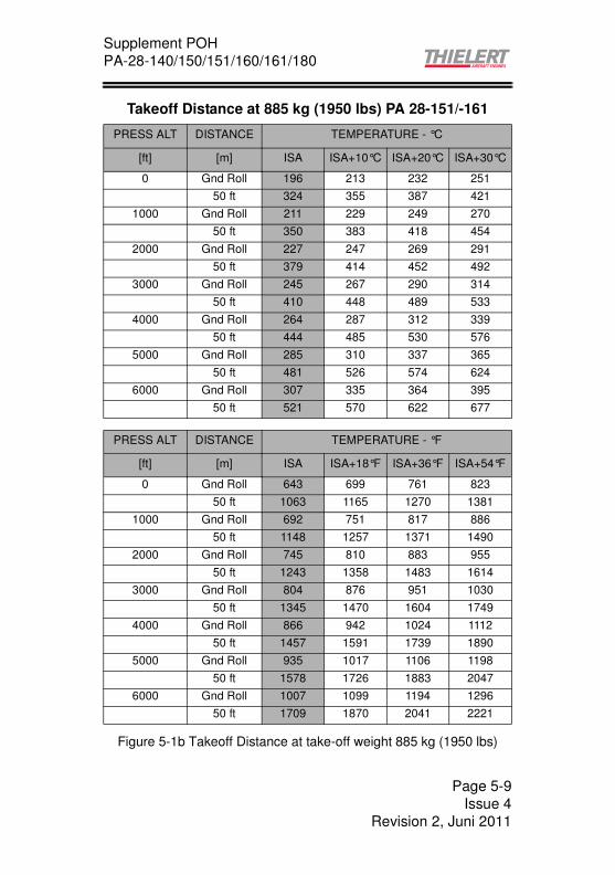
Supplement POH
PA-28-140/150/151/160/161/180
Takeoff Distance at 885 kg (1950 lbs) PA 28-151/-161
Figure 5-1b Takeoff Distance at take-off weight 885 kg (1950 lbs)
PRESS ALT DISTANCE TEMPERATURE - °C
[ft] [m] ISA ISA+10°C ISA+20°C ISA+30°C
0 Gnd Roll 196 213 232 251
50 ft 324 355 387 421
1000 Gnd Roll 211 229 249 270
50 ft 350 383 418 454
2000 Gnd Roll 227 247 269 291
50 ft 379 414 452 492
3000 Gnd Roll 245 267 290 314
50 ft 410 448 489 533
4000 Gnd Roll 264 287 312 339
50 ft 444 485 530 576
5000 Gnd Roll 285 310 337 365
50 ft 481 526 574 624
6000 Gnd Roll 307 335 364 395
50 ft 521 570 622 677
PRESS ALT DISTANCE TEMPERATURE - °F
[ft] [m] ISA ISA+18°F ISA+36°F ISA+54°F
0 Gnd Roll 643 699 761 823
50 ft 1063 1165 1270 1381
1000 Gnd Roll 692 751 817 886
50 ft 1148 1257 1371 1490
2000 Gnd Roll 745 810 883 955
50 ft 1243 1358 1483 1614
3000 Gnd Roll 804 876 951 1030
50 ft 1345 1470 1604 1749
4000 Gnd Roll 866 942 1024 1112
50 ft 1457 1591 1739 1890
5000 Gnd Roll 935 1017 1106 1198
50 ft 1578 1726 1883 2047
6000 Gnd Roll 1007 1099 1194 1296
50 ft 1709 1870 2041 2221
Page 5-9
Issue 4
Revision 2, Juni 2011

Supplement POH
PA-28-140/150/151/160/161/180
TAKE-OFF DISTANCE for PA-28-140/-150/-160/-180
Conditions:
Flaps 10°
Full Power Prior to Brake Release
Paved, level, dry runway
Zero Wind
Lift-off speed: 57 KIAS
Speed at 15 m (50 ft): 65 KIAS
Notes:
(1) Decrease distances 10% for each 9 Knots headwind;
Increase distances 10% for each 2 Knots of tailwind up to
10 Knots.
(2) For operation on dry, grass runway, increase distances by
15% of the "ground roll" figure.
(3) Consider additionals for wet grass runway, softened
ground or snow.
Page 5-10
Issue 4
Revision 2, Juni 2011

Supplement POH
PA-28-140/150/151/160/161/180
Takeoff Distance at 976 kg (2150 lbs) PA 28-140/-150/-160/-180
Figure 5-1c Takeoff Distance at take-off weight 976 kg (2150 lbs)
PRESS ALT DISTANCE TEMPERATURE - °C
[ft] [m] ISA ISA+10°C ISA+20°C ISA+30°C
0 Gnd Roll 297 323 352 381
50 ft 543 594 648 705
1000 Gnd Roll 320 348 379 410
50 ft 587 642 701 760
2000 Gnd Roll 345 345 408 442
50 ft 635 694 758 824
3000 Gnd Roll 371 405 440 477
50 ft 686 751 820 892
4000 Gnd Roll 401 436 474 514
50 ft 743 813 887 965
5000 Gnd Roll 432 471 512 555
50 ft 805 880 961 1046
6000 Gnd Roll 467 508 553 599
50 ft 872 954 1041 1133
PRESS ALT DISTANCE TEMPERATURE - °F
[ft] [m] ISA ISA+18°F ISA+36°F ISA+54°F
0 Gnd Roll 974 1060 1155 1250
50 ft 1781 1949 2126 2313
1000 Gnd Roll 1050 1142 1243 1345
50 ft 1926 2106 2300 2493
2000 Gnd Roll 1132 1132 1339 1450
50 ft 2083 2277 2487 2703
3000 Gnd Roll 1217 1329 1444 1565
50 ft 2251 2464 2690 2927
4000 Gnd Roll 1316 1430 1555 1686
50 ft 2438 2667 2910 3166
5000 Gnd Roll 1417 1545 1680 1821
50 ft 2641 2887 3153 3432
6000 Gnd Roll 1532 1667 1814 1965
50 ft 2861 3130 3415 3717
Page 5-11
Issue 4
Revision 2, Juni 2011

Supplement POH
PA-28-140/150/151/160/161/180
Takeoff Distance at 885 kg (1950 lbs) PA 28-140/-150/-160/-180
Figure 5-1d Takeoff Distance at take-off weight 885 kg (1950 lbs)
PRESS ALT DISTANCE TEMPERATURE - °C
[ft] [m] ISA ISA+10°C ISA+20°C ISA+30°C
0 Gnd Roll 231 251 273 296
50 ft 422 462 504 548
1000 Gnd Roll 249 271 294 319
50 ft 456 499 545 594
2000 Gnd Roll 268 292 317 344
50 ft 493 540 589 641
3000 Gnd Roll 289 314 342 370
50 ft 534 584 637 693
4000 Gnd Roll 311 339 396 400
50 ft 578 632 690 750
5000 Gnd Roll 336 366 398 431
50 ft 626 684 747 813
6000 Gnd Roll 363 395 430 465
50 ft 678 742 810 881
PRESS ALT DISTANCE TEMPERATURE - °F
[ft] [m] ISA ISA+18°F ISA+36°F ISA+54°F
0 Gnd Roll 758 823 896 971
50 ft 1385 1516 1654 1798
1000 Gnd Roll 817 889 965 1047
50 ft 1496 1637 1788 1949
2000 Gnd Roll 879 958 1040 1129
50 ft 1617 1772 1932 2103
3000 Gnd Roll 948 1030 1122 1214
50 ft 1752 1916 2090 2274
4000 Gnd Roll 1020 1112 1299 1312
50 ft 1896 2073 2264 2461
5000 Gnd Roll 1102 1201 1306 1414
50 ft 2054 2244 2451 2667
6000 Gnd Roll 1191 1296 1411 1526
50 ft 2224 2434 2657 2890
Page 5-12
Issue 4
Revision 2, Juni 2011

Supplement POH
PA-28-140/150/151/160/161/180
MAXIMUM CLIMBSPEED for PA-28-151/-161
Conditions:Take-off weight 1055 kg (2325 lbs)
Climb speed Vy = 70 KIAS
Flaps Up
Full Power
Figure 5-2a Climbspeed, PA-28-151/-161, 1055 kg (2325 lbs)
Pressure
altitude
[FT]
Climbspeed (ft/min)
ISA ISA + 10°C
(ISA + 18°F)
ISA + 20°C
(ISA + 36°F)
ISA + 30°C
(ISA + 54°F)
0 606 606 602 595
1000 606 602 595 584
2000 603 596 585 569
3000 597 586 571 549
4000 588 572 552 523
5000 574 554 528 495
6000 556 531 500 461
7000 533 503 468 422
8000 506 470 431 380
9000 474 433 390 335
10000 437 392 346 287
11000 396 348 299 237
12000 351 301 251
Page 5-13
Issue 4
Revision 2, Juni 2011
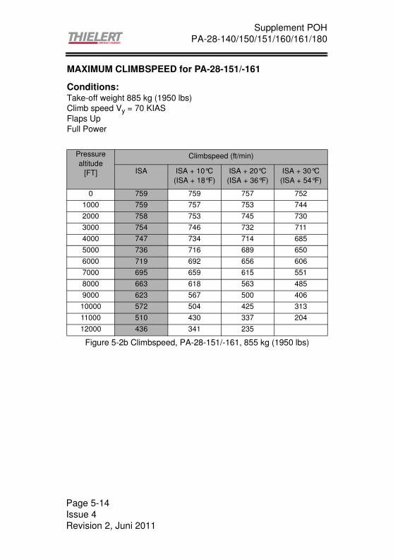
Supplement POH
PA-28-140/150/151/160/161/180
MAXIMUM CLIMBSPEED for PA-28-151/-161
Conditions:Take-off weight 885 kg (1950 lbs)
Climb speed Vy = 70 KIAS
Flaps Up
Full Power
Figure 5-2b Climbspeed, PA-28-151/-161, 855 kg (1950 lbs)
Pressure
altitude
[FT]
Climbspeed (ft/min)
ISA ISA + 10°C
(ISA + 18°F)
ISA + 20°C
(ISA + 36°F)
ISA + 30°C
(ISA + 54°F)
0 759 759 757 752
1000 759 757 753 744
2000 758 753 745 730
3000 754 746 732 711
4000 747 734 714 685
5000 736 716 689 650
6000 719 692 656 606
7000 695 659 615 551
8000 663 618 563 485
9000 623 567 500 406
10000 572 504 425 313
11000 510 430 337 204
12000 436 341 235
Page 5-14
Issue 4
Revision 2, Juni 2011
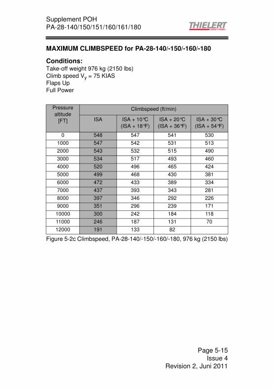
Supplement POH
PA-28-140/150/151/160/161/180
MAXIMUM CLIMBSPEED for PA-28-140/-150/-160/-180
Conditions:Take-off weight 976 kg (2150 lbs)
Climb speed Vy = 75 KIAS
Flaps Up
Full Power
Figure 5-2c Climbspeed, PA-28-140/-150/-160/-180, 976 kg (2150 lbs)
Pressure
altitude
[FT]
Climbspeed (ft/min)
ISA ISA + 10°C
(ISA + 18°F)
ISA + 20°C
(ISA + 36°F)
ISA + 30°C
(ISA + 54°F)
0 548 547 541 530
1000 547 542 531 513
2000 543 532 515 490
3000 534 517 493 460
4000 520 496 465 424
5000 499 468 430 381
6000 472 433 389 334
7000 437 393 343 281
8000 397 346 292 226
9000 351 296 239 171
10000 300 242 184 118
11000 246 187 131 70
12000 191 133 82
Page 5-15
Issue 4
Revision 2, Juni 2011

Supplement POH
PA-28-140/150/151/160/161/180
MAXIMUM CLIMBSPEED for PA-28-140/-150/-160/-180
Conditions:Take-off weight 885 kg (1950 lbs)
Climb speed Vy = 75 KIAS
Flaps Up
Full Power
Figure 5-2d Climbspeed, PA-28-140/-150/-160/-180, 855 kg (1950 lbs)
Pressure
altitude
[FT]
Climbspeed (ft/min)
ISA ISA + 10°C
(ISA + 18°F)
ISA + 20°C
(ISA + 36°F)
ISA + 30°C
(ISA + 54°F)
0 657 653 643 627
1000 654 644 629 607
2000 646 631 610 583
3000 633 612 586 552
4000 615 589 557 517
5000 592 560 523 477
6000 564 526 484 431
7000 531 487 440 381
8000 492 444 391 325
9000 449 395 337 264
10000 400 431 279 198
11000 346 282 215 126
12000 287 218 146
Page 5-16
Issue 4
Revision 2, Juni 2011

Supplement POH
PA-28-140/150/151/160/161/180
TIME, FUEL AND DISTANCE TO CLIMB for PA-28-151/-161
Notes :
(1) Add 1 l (0.3 US gal) of fuel for engine start, taxi and takeoff
allowance.
(2) Increase time and distance by 10% for 10°C/ 18°F above
standard temperature.
(3) Distances shown are based on zero wind.
(4) Time, distance and fuel required are only valid from the
point where the airplane climbs at vy = 70 KIAS.
Conditions:
Takeoff weight 1055 kg (2325 lbs); Climb speed vy = 70 KIAS
Flaps Up; Full Power; Zero wind, Standard Temperature
Figure 5-3a Time, Fuel and Distance to Climb at 1055 kg (2325 lbs)
PA-28-151/-161
From Sea Level
Press.
Alt.Temp. (ISA)
Rate of
ClimbTime
Distance
to climbFuel used
[ft] [°C] [°F] [ft/min] [MIN] [NM] [US gal] [l]
0 15 59 606 0.0 0.0 0.0 0.0
1000 13 55 606 1.6 1.9 0.2 0.8
2000 11 52 603 3.3 3.9 0.4 1.6
3000 9 48 597 5.0 6.0 0.7 2.5
4000 7 45 588 6.7 8.1 0.9 3.4
5000 5 41 574 8.4 10.4 1.1 4.3
6000 3 38 556 10.1 12.8 1.4 5.3
7000 1 34 533 12.0 15.3 1.7 6.3
8000 -1 30 506 13.9 18.0 2.0 7.4
9000 -3 27 474 15.9 21.0 2.2 8.5
10000 -5 23 437 18.1 24.3 2.6 9.7
11000 -7 20 396 20.5 27.9 2.9 11.0
12000 -9 16 351 23.2 32.1 3.2 12.3
Page 5-17
Issue 4
Revision 2, Juni 2011

Supplement POH
PA-28-140/150/151/160/161/180
Conditions:
Takeoff weight 885 kg (1950 lbs); Climb speed vy = 70 KIAS
Flaps Up; Full Power; Zero wind, Standard Temperature
Figure 5-3b Time, Fuel and Distance to Climb at 885 kg (1950 lbs)
PA-28-151/-161
From Sea Level
Press.
Alt.Temp. (ISA)
Rate of
ClimbTime
Distance
to climbFuel used
[ft] [°C] [°F] [ft/min] [MIN] [NM] [US gal] [l]
0 15 59 759 0.0 0.0 0.0 0.0
1000 13 55 759 1.3 1.5 0.2 0.6
2000 11 52 758 2.6 3.1 0.3 1.3
3000 9 48 754 4.0 4.8 0.5 2.0
4000 7 45 747 5.3 6.5 0.7 2.7
5000 5 41 736 6.6 8.2 0.9 3.5
6000 3 38 719 8.0 10.1 1.1 4.3
7000 1 34 695 9.4 12.0 1.4 5.2
8000 -1 30 663 10.9 14.1 1.6 6.0
9000 -3 27 623 12.5 16.4 1.8 7.0
10000 -5 23 572 14.1 18.9 2.1 7.9
11000 -7 20 510 16.0 21.7 2.4 9.0
12000 -9 16 436 18.1 25.0 2.7 10.1
Page 5-18
Issue 4
Revision 2, Juni 2011

Supplement POH
PA-28-140/150/151/160/161/180
TIME, FUEL AND DISTANCE TO CLIMBfor PA-28-140/-150/-160/-180
Notes :
(1) Add 1 l (0.3 US gal) of fuel for engine start, taxi and takeoff .
(2) Increase time and distance by 10% for 10°C/ 18°F above
standard temperature.
(3) Distances shown are based on zero wind.
(4) Time, distance and fuel required are only valid from the
point where the airplane climbs at vy = 75 KIAS.
Conditions:
Takeoff weight 976 kg (2150 lbs); Climb speed vy = 75 KIAS
Flaps Up; Full Power; Zero wind, Standard Temperature
Figure 5-3c Time, Fuel and Distance to Climb at 976 kg (2150 lbs)
PA-28-140/-150/-160/-180
From Sea Level
Press.
Alt.Temp. (ISA)
Rate of
ClimbTime
Distance
to climbFuel used
[ft] [°C] [°F] [ft/min] [MIN] [NM] [US gal] [l]
0 15 59 548 0.0 0.0 0.0 0.0
1000 13 55 547 1.8 2.2 0.2 0.9
2000 11 52 543 3.7 4.4 0.5 1.8
3000 9 48 534 5.5 6.8 0.7 2.7
4000 7 45 520 7.4 9.2 1.0 3.7
5000 5 41 499 9.4 11.9 1.2 4.7
6000 3 38 472 11.4 14.7 1.6 5.9
7000 1 34 437 13.6 17.8 1.9 7.1
8000 -1 30 397 16.0 21.3 2.2 8.4
9000 -3 27 351 18.7 25.2 2.6 9.8
10000 -5 23 300 21.8 29.8 3.0 11.3
11000 -7 20 246 25.4 35.3 3.4 13.0
12000 -9 16 191 30.0 42.4 4.0 15.1
Page 5-19
Issue 4
Revision 2, Juni 2011
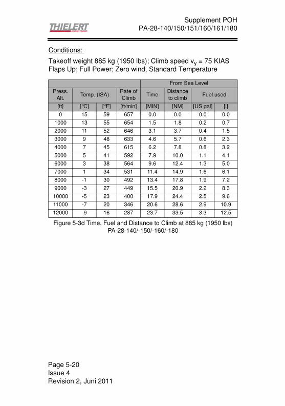
Supplement POH
PA-28-140/150/151/160/161/180
Conditions:
Takeoff weight 885 kg (1950 lbs); Climb speed vy = 75 KIAS
Flaps Up; Full Power; Zero wind, Standard Temperature
Figure 5-3d Time, Fuel and Distance to Climb at 885 kg (1950 lbs)
PA-28-140/-150/-160/-180
From Sea Level
Press.
Alt.Temp. (ISA)
Rate of
ClimbTime
Distance
to climbFuel used
[ft] [°C] [°F] [ft/min] [MIN] [NM] [US gal] [l]
0 15 59 657 0.0 0.0 0.0 0.0
1000 13 55 654 1.5 1.8 0.2 0.7
2000 11 52 646 3.1 3.7 0.4 1.5
3000 9 48 633 4.6 5.7 0.6 2.3
4000 7 45 615 6.2 7.8 0.8 3.2
5000 5 41 592 7.9 10.0 1.1 4.1
6000 3 38 564 9.6 12.4 1.3 5.0
7000 1 34 531 11.4 14.9 1.6 6.1
8000 -1 30 492 13.4 17.8 1.9 7.2
9000 -3 27 449 15.5 20.9 2.2 8.3
10000 -5 23 400 17.9 24.4 2.5 9.6
11000 -7 20 346 20.6 28.6 2.9 10.9
12000 -9 16 287 23.7 33.5 3.3 12.5
Page 5-20
Issue 4
Revision 2, Juni 2011
Supplement POH
PA-28-140/150/151/160/161/180
CRUISE PERFORMANCE, RANGE AND ENDURANCEfor PA-28-151/-161
Conditions:Flaps Up
Zero wind
Notes:
(1) Endurance information are based on fuel tanks with a ca-
pacity of 162.8 l (43 US gal) usable fuel and include a re-
serve of 45 min at 55% power (11.1 l / 2.9 US gal).
(2) Increase true airspeed and range by 2% per 10°C (18°F)
above ISA temperature. Decrease true airspeed and range
by 2% per 10°C (18°F) below ISA temperature.
Page 5-21
Issue 4
Revision 2, Juni 2011

Supplement POH
PA-28-140/150/151/160/161/180
Cruise Performance, Range and Endurancefor PA-28-151/-161 at 1055 kg (2325 lbs)
Figure 5-4a Cruise Performance, Range and Endurance
at 1055 kg (2325 lbs)
Press.Alt. [ft] Load [%] KTAS FF[l/h] FF [US gal/h] NM Hrs
2000 60 88 17.4 4.6 819 9.3
2000 70 95 19.4 5.1 793 8.4
2000 80 101 22.1 5.8 740 7.3
2000 90 106 25.6 6.8 671 6.3
4000 60 90 17.4 4.6 838 9.3
4000 70 97 19.4 5.1 810 8.4
4000 80 102 22.1 5.8 748 7.3
4000 90 107 25.6 6.8 677 6.3
6000 60 91 17.4 4.6 847 9.3
6000 70 98 19.4 5.1 818 8.4
6000 80 104 22.1 5.8 762 7.3
6000 90 109 25.6 6.8 690 6.3
8000 60 93 17.4 4.6 866 9.3
8000 70 100 19.4 5.1 835 8.4
8000 80 106 22.1 5.8 777 7.3
8000 90 111 25.6 6.8 702 6.3
10000 60 94 17.4 4.6 875 9.3
10000 70 101 19.4 5.1 843 8.4
10000 80 108 22.1 5.8 792 7.3
12000 60 96 17.4 4.6 894 9.3
12000 70 103 19.4 5.1 860 8.4
12000 80 110 22.1 5.8 806 7.3
Page 5-22
Issue 4
Revision 2, Juni 2011

Supplement POH
PA-28-140/150/151/160/161/180
Cruise Performance, Range and Endurancefor PA-28-151/-161 at 885 kg (1950 lbs)
Figure 5-4b Cruise Performance, Range and Endurance
at 885 kg (1950 lbs)
Press.Alt. [ft] Load [%] KTAS FF[l/h] FF [US gal/h] NM Hrs
2000 60 100 17.4 4.6 931 9.3
2000 70 106 19.4 5.1 885 8.4
2000 80 112 22.1 5.8 821 7.3
2000 90 117 25.6 6.8 740 6.3
4000 60 101 17.4 4.6 940 9.3
4000 70 108 19.4 5.1 902 8.4
4000 80 114 22.1 5.8 836 7.3
4000 90 119 25.6 6.8 753 6.3
6000 60 103 17.4 4.6 959 9.3
6000 70 110 19.4 5.1 919 8.4
6000 80 116 22.1 5.8 850 7.3
6000 90 121 25.6 6.8 766 6.3
8000 60 105 17.4 4.6 978 9.3
8000 70 112 19.4 5.1 935 8.4
8000 80 118 22.1 5.8 865 7.3
8000 90 123 25.6 6.8 778 6.3
10000 60 107 17.4 4.6 996 9.3
10000 70 114 19.4 5.1 952 8.4
10000 80 120 22.1 5.8 880 7.3
12000 60 109 17.4 4.6 1015 9.3
12000 70 116 19.4 5.1 969 8.4
12000 80 123 22.1 5.8 902 7.3
Page 5-23
Issue 4
Revision 2, Juni 2011

Supplement POH
PA-28-140/150/151/160/161/180
CRUISE PERFORMANCE, RANGE AND ENDURANCEfor PA-28-140/-150/-160/-180
Conditions:Flaps Up
Zero wind
Notes:
(1) Endurance information are based on fuel tanks with a ca-
pacity of 162.8 l (43 US gal) usable fuel and include a re-
serve of 45 min at 55% power (11.1 l / 2.9 US gal).
(2) Increase true airspeed and range by 2% per 10°C (18°F)
above ISA temperature. Decrease true airspeed and range
by 2% per 10°C/ (18°F) below ISA temperature.
Page 5-24
Issue 4
Revision 2, Juni 2011

Supplement POH
PA-28-140/150/151/160/161/180
Cruise Performance, Range and Endurancefor PA-28-140/-150/-160/-180 at 976 kg (2150 lbs)
Figure 5-4c Cruise Performance, Range and Endurance
at 976 kg (2150 lbs)
Press.Alt. [ft] Load [%] KTAS FF[l/h] FF [US gal/h] NM Hrs
2000 60 85 17.4 4.6 791 9.3
2000 70 94 19.4 5.1 785 8.4
2000 80 102 22.1 5.8 748 7.3
2000 90 109 25.6 6.8 690 6.3
4000 60 85 17.4 4.6 791 9.3
4000 70 95 19.4 5.1 793 8.4
4000 80 103 22.1 5.8 755 7.3
4000 90 110 25.6 6.8 696 6.3
6000 60 86 17.4 4.6 801 9.3
6000 70 96 19.4 5.1 802 8.4
6000 80 104 22.1 5.8 762 7.3
6000 90 112 25.6 6.8 709 6.3
8000 60 87 17.4 4.6 810 9.3
8000 70 97 19.4 5.1 810 8.4
8000 80 105 22.1 5.8 770 7.3
8000 90 113 25.6 6.8 715 6.3
10000 60 87 17.4 4.6 810 9.3
10000 70 98 19.4 5.1 818 8.4
10000 80 107 22.1 5.8 784 7.3
12000 60 88 17.4 4.6 819 9.3
12000 70 99 19.4 5.1 827 8.4
12000 80 108 22.1 5.8 792 7.3
Page 5-25
Issue 4
Revision 2, Juni 2011

Supplement POH
PA-28-140/150/151/160/161/180
Cruise Performance, Range and Endurancefor PA-28-151/-161 at 885 kg (1950 lbs)
Figure 5-4d Cruise Performance, Range and Endurance
at 885 kg (1950 lbs)
Press.Alt. [ft] Load [%] KTAS FF[l/h] FF [US gal/h] NM Hrs
2000 60 93 17.4 4.6 866 9.3
2000 70 102 19.4 5.1 852 8.4
2000 80 110 22.1 5.8 806 7.3
2000 90 118 25.6 6.8 747 6.3
4000 60 94 17.4 4.6 875 9.3
4000 70 104 19.4 5.1 868 8.4
4000 80 112 22.1 5.8 821 7.3
4000 90 119 25.6 6.8 753 6.3
6000 60 95 17.4 4.6 884 9.3
6000 70 105 19.4 5.1 877 8.4
6000 80 113 22.1 5.8 828 7.3
6000 90 121 25.6 6.8 766 6.3
8000 60 96 17.4 4.6 894 9.3
8000 70 106 19.4 5.1 885 8.4
8000 80 115 22.1 5.8 843 7.3
8000 90 123 25.6 6.8 778 6.3
10000 60 97 17.4 4.6 903 9.3
10000 70 108 19.4 5.1 902 8.4
10000 80 117 22.1 5.8 858 7.3
12000 60 98 17.4 4.6 912 9.3
12000 70 109 19.4 5.1 910 8.4
12000 80 118 22.1 5.8 865 7.3
Page 5-26
Issue 4
Revision 2, Juni 2011

Supplement POH
PA-28-140/150/151/160/161/180
GLIDE RANGEPA 28-151/-161
Conditions:Take-off weight 1055 kg (2325 lbs)
Propeller windmilling
Flaps 0°, Zero wind, 73 KIAS
Figure 5-5a Glide Range PA 28-151/-161
Glide Distance Propeller Windmilling
0
2000
4000
6000
8000
10000
12000
14000
0 5 10 15 20
Glide Range [Nm]
Pre
ss
ure
Alt
itu
de
[ft
]
Page 5-27
Issue 4
Revision 2, Juni 2011

Supplement POH
PA-28-140/150/151/160/161/180
GLIDE RANGEPA 28-140/-150/-160/-180
Conditions:Take-off weight 976 kg (2150 lbs)
Propeller windmilling
Flaps 0°, Zero wind, 78 KIAS
Figure 5-5b Glide Range PA 28-140/-150/-160/-180
Glide Distance, Propeller Windmilling
0
2000
4000
6000
8000
10000
12000
14000
0 5 10 15 20
Glide Range [Nm]
Pre
ss
ure
Alt
itu
de
[ft
]
Page 5-28
Issue 4
Revision 2, Juni 2011

Supplement POH
PA-28-140/150/151/160/161/180
Figure 5-6a Engine Power Diagram
Page 5-29
Issue 4
Revision 2, Juni 2011
Supplement POH
PA-28-140/150/151/160/161/180
This page is intentionally left blank
Page 5-30
Issue 4
Revision 2, Juni 2011

Supplement POH
PA-28-140/150/151/160/161/180
SECTION 6WEIGHT & BALANCE
MODEL PA-28-151/-161 with TAE-125
AIRPLANE BASIC EMPTY WEIGHT
* The standard empty weight includes full engine oil capacity,
full gearbox oil capacity, full coolant capacity and 8 l (2 US gal)
unusable fuel.
AIRPLANE USEFUL LOAD
(Ramp Weight) - (Basic Empty Weight) = Useful Load
(Normal category: 1056 kg) - (.............kg) = kg
(2327 lb) - (..............lb) = lb
(PA 28-161 Utility cat.: 917 kg) - (.............kg) = kg
(2022 lb) - (..............lb) = lb
(PA 28-151 Utility cat.: 886 kg) - (.............kg) = kg
(1952 lb) - (..............lb) = lb
THIS BASIC EMPTY WEIGHT, C.G. AND USEFUL LOAD ARE
FOR THE AIRPLANE AS INSPECTED AFTER
MODIFICATION. REFER TO APPROPRIATE AIRCRAFT
RECORD WHEN ALTERATIONS HAVE BEEN MADE.
WEIGHT & BALANCE DATA FORMFigure 6-5a
Airplane Serial Number:
Registration Number:
Date:
Item
Weight x C.G. Arm = Moment
(kg/ lb) (m/ in Aft (kgm/ lbs in)
of Datum)
Standard Empty
Weight
Actual:
Computed:
Optional
Equipment
Basic Empty
Weight
Page 6-1
Issue 4
Revision -, Feb. 2010

Supplement POH
PA-28-140/150/151/160/161/180
MODEL PA-28-140 with TAE-125
AIRPLANE BASIC EMPTY WEIGHT
* The standard empty weight includes full engine oil capacity,
full gearbox oil capacity, full coolant capacity and 8 l (2 US gal)
unusable fuel.
AIRPLANE USEFUL LOAD
(Ramp Weight) - (Basic Empty Weight) = Useful Load
(Normal category: 977 kg*) - (.............kg) = kg
(2152 lb*) - (..............lb) = lb
(Normal category: 886 kg*) - (.............kg) = kg
(1952 lb*) - (..............lb) = lb
(Utility category: 886 kg) - (.............kg) = kg
(1952 lb) - (..............lb) = lb
THIS BASIC EMPTY WEIGHT, C.G. AND USEFUL LOAD ARE
FOR THE AIRPLANE AS INSPECTED AFTER
MODIFICATION. REFER TO APPROPRIATE AIRCRAFT
RECORD WHEN ALTERATIONS HAVE BEEN MADE.
WEIGHT & BALANCE DATA FORMFigure 6-5b
*Serial no. 28-20001 to 28-20939: 886 kg, if Piper Kit 756962
installed 997 kg, Serial no. 28-20940 and up: 977 kg. Refer to
original POH.
Airplane Serial Number:
Registration Number:
Date:
Item
Weight x C.G. Arm = Moment
(kg/ lb) (m/ in Aft (kgm/ lbs in)
of Datum)
Standard Empty
Weight
Actual:
Computed:
Optional
Equipment
Basic Empty
Weight
Page 6-2
Issue 4
Revision -, Feb. 2010
Supplement POH
PA-28-140/150/151/160/161/180
MODEL PA-28-150/-160/-180 with TAE-125
AIRPLANE BASIC EMPTY WEIGHT
* The standard empty weight includes full engine oil capacity,
full gearbox oil capacity, full coolant capacity and 8 l (2 US gal)
unusable fuel.
AIRPLANE USEFUL LOAD
(Ramp Weight) - (Basic Empty Weight) = Useful Load
(Normal category: 977 kg) - (.............kg) = kg
(2152 lb) - (.............lb ) = lb
(PA 28-180 Utility cat.: 886 kg) - (.............kg) = kg
(1952 lb) - (..............lb) = lb
THIS BASIC EMPTY WEIGHT, C.G. AND USEFUL LOAD ARE
FOR THE AIRPLANE AS INSPECTED AFTER
MODIFICATION. REFER TO APPROPRIATE AIRCRAFT
RECORD WHEN ALTERATIONS HAVE BEEN MADE.
WEIGHT & BALANCE DATA FORMFigure 6-5b
Airplane Serial Number:
Registration Number:
Date:
Item
Weight x C.G. Arm = Moment
(kg/ lb) (m/ in Aft (kgm/ lbs in)
of Datum)
Standard Empty
Weight
Actual:
Computed:
Optional
Equipment
Basic Empty
Weight
Page 6-3
Issue 4
Revision -, Feb. 2010

Supplement POH
PA-28-140/150/151/160/161/180
WEIGHT & BALANCE DETERMINATION FOR FLIGHT
(a) Add the weight of all items to be loaded to the basic empty
weight.
(b) Use the Loading Graph (Figure 6-13) to determine the mo-
ment of all items to be carried in the airplane.
(c) Add the moment of all items to be loaded to the basic empty
weight moment.
(d) Divide the total moment by the total weight to determine the
C.G. location.
(e) By using the figures of item (a) and (d) (above), locate a
point on the C.G. range and weight graph (Figure 6-15). If
the point falls within the C.G. envelope, the loading meets
the weight and balance requirements.
Page 6-4
Issue 4
Revision -, Feb. 2010

Supplement POH
PA-28-140/150/151/160/161/180
WEIGHT & BALANCE LOADING FORM PA 28-151/-161
* Utility Category Operation - No baggage or aft passengers
allowed. Maximum baggage as per original POH
Totals must be within approved weight and C.G. limits. It is the
responsibility of the airplane owner and the pilot to insure that
the airplane is loaded properly. The Basic Empty Weight C.G. is
noted on the Weight & Balance Data Form (Figure 6-5a). If the
airplane has been altered, refer to the Weight and Balance
Record for this information.
Figure 6-11a
Weight
(kg)
Arm Aft
Datum (m)
Moment
(kgm)
- Basic Empty Weight
- Pilot and Front Passenger 2.04
- Passengers (Rear Seats)* 3.00
- Fuel (max. 162.8 l usable) 2.41
- Baggage* (max. 90 kg,
PA 28-161 Cadet max. 23 kg)3.63
- Ramp Weight
PA 28-151 (1056 kg Normal
aircraft, 886 kg Utility, Maximum)
PA 28-161 (1056 kg Normal aircraft,
917 kg Utility Maximum)
- Fuel Allowance for Engine Start,
Taxi and Run up-1 2.41 -2.41
- Take-off Weight
PA 28-151 (1055 kg Normal
aircraft, 885 kg Utility, Maximum)
PA 28-161 (1055 kg Normal, 916 kg
Utility, Maximum)
Page 6-5
Issue 4
Revision -, Feb. 2010

Supplement POH
PA-28-140/150/151/160/161/180
WEIGHT & BALANCE LOADING FORM PA 28-151/-161
* Utility Category Operation - No baggage or aft passengers
allowed. Maximum baggage as per original POH
Totals must be within approved weight and C.G. limits. It is the
responsibility of the airplane owner and the pilot to insure that
the airplane is loaded properly. The Basic Empty Weight C.G. is
noted on the Weight & Balance Data Form (Figure 6-5a). If the
airplane has been altered, refer to the Weight and Balance
Record for this information.
Figure 6-11a
Weight
(lb)
Arm Aft
Datum (in)
Moment
(lbs in)
- Basic Empty Weight
- Pilot and Front Passenger 80.5
- Passengers (Rear Seats)* 118.1
- Fuel (max. 43 gal usable) 95
- Baggage* (max. 200 lbs)
PA 28-161 Cardet max. 50 lbs)142.8
- Ramp Weight
PA 28-151 (2327 lbs Normal
aircraft, 1952 lbs Utility, Maximum)
PA 28-161 (2327 lbs Normal
aircraft, 2022 lbs Utility Maximum)
- Fuel Allowance for Engine Start,
Taxi and Run up-2 95 -190
- Take-off Weight
PA 28-151 (2325 lbs Normal aircraft,
1950 lbs Utility, Maximum)
PA 28-161 (2325 lbs Normal, 2020
lbs Utility Maximum)
Page 6-6
Issue 4
Revision -, Feb. 2010
Supplement POH
PA-28-140/150/151/160/161/180
WEIGHT & BALANCE LOADING FORM
PA 28-140
* Utility Category Operation - No baggage or aft passengers
allowed. Maximum baggage as per original POH
**See next page
Totals must be within approved weight and C.G. limits. It is the
responsibility of the airplane owner and the pilot to insure that
the airplane is loaded properly. The Basic Empty Weight C.G. is
noted on the Weight & Balance Data Form (Figure 6-5b). If the
airplane has been altered, refer to the Weight and Balance
Record for this information.
Figure 6-11b
Weight
(kg)
Arm Aft
Datum (m)
Moment
(kgm)
- Basic Empty Weight
- Pilot and Front Passenger 2.17
- Passengers (Rear Seats)* 2.97
- Fuel (max. 162 l usable) 2.41
- Baggage* , Area 1** 2.97
- Baggage* , Area 2** 3.39
- Ramp Weight
(977 kg Normal aircraft, 886 kg
Utility Maximum)
- Fuel Allowance for Engine Start,
Taxi and Run up-1 2.41 -2.41
- Take-off Weight
(976 kg Normal, 885 kg Utility
Maximum)
Page 6-7
Issue 4
Revision -, Feb. 2010

Supplement POH
PA-28-140/150/151/160/161/180
WEIGHT & BALANCE LOADING FORM
PA 28-140
* Utility Category Operation - No baggage or aft passengers
allowed. Maximum baggage as per original POH
**For normal category see next page.
Totals must be within approved weight and C.G. limits. It is the
responsibility of the airplane owner and the pilot to insure that
the airplane is loaded properly. The Basic Empty Weight C.G. is
noted on the Weight & Balance Data Form (Figure 6-5b). If the
airplane has been altered, refer to the Weight and Balance
Record for this information.
Figure 6-11b
Weight
(lb)
Arm Aft
Datum (in)
Moment
(lbs in)
- Basic Empty Weight
- Pilot and Front Passenger 85.5
- Passengers (Rear Seats)* 117
- Fuel (max. 43 gal usable) 95
- Baggage*, Area 1** 117
- Baggage*, Area 2** 133
- Ramp Weight
(2152 lbs Normal aircraft,1952 lbs
Utility Maximum)
- Fuel Allowance for Engine Start,
Taxi and Run up-2 95 -190
- Take-off Weight
(2150 lbs Normal, 1950 lbs Utility
Maximum)
Page 6-8
Issue 4
Revision -, Feb. 2010

Supplement POH
PA-28-140/150/151/160/161/180
** Refer to original POH for limitations:Maximum allowable baggage for the PA 28-140 as normal category aircraft:
Serial no. 28-20001 through 28-20939:
Baggage area 1: 45 kg (100 lbs)
90 kg (200 lbs), if Piper Kit 756962 is being
installed
Baggage area 2: 45 kg (100 lbs), if Piper Kit 756962 is being
installed and when modified in accordance
with Piper Drawing 66671
Serial no. 28-20940 and up:
Baggage area 1: 90 kg (200 lbs)
Baggage area 2: 45 kg (100 lbs), when modified in
accordance with Piper Drawing 66671
Page 6-9
Issue 4
Revision -, Feb. 2010

Supplement POH
PA-28-140/150/151/160/161/180
WEIGHT & BALANCE LOADING FORM
PA 28-150/-160/-180
* Utility Category Operation - No baggage or aft passengers
allowed. Maximum baggage as per original POH
Totals must be within approved weight and C.G. limits. It is the
responsibility of the airplane owner and the pilot to insure that
the airplane is loaded properly. The Basic Empty Weight C.G. is
noted on the Weight & Balance Data Form (Figure 6-5c). If the
airplane has been altered, refer to the Weight and Balance
Record for this information.
Figure 6-11c
Weight
(kg)
Arm Aft
Datum (m)
Moment
(kgm)
- Basic Empty Weight
- Pilot and Front Passenger 2.17
- Passengers (Rear Seats)* 3.00
- Fuel (max. 162 l usable) 2.41
- Baggage* (max. 90 kg) 3.63
- Ramp Weight
(977 kg Normal aircraft, 886 kg
Utility Maximum)
- Fuel Allowance for Engine Start,
Taxi and Run up-1 2.41 -2.41
- Take-off Weight
(976 kg Normal, 885 kg Utility
Maximum)
Page 6-10
Issue 4
Revision -, Feb. 2010

Supplement POH
PA-28-140/150/151/160/161/180
WEIGHT & BALANCE LOADING FORM
PA 28-150/-160/-180
* Utility Category Operation - No baggage or aft passengers
allowed. Maximum baggage as per original POH
Totals must be within approved weight and C.G. limits. It is the
responsibility of the airplane owner and the pilot to insure that
the airplane is loaded properly. The Basic Empty Weight C.G. is
noted on the Weight & Balance Data Form (Figure 6-5c). If the
airplane has been altered, refer to the Weight and Balance
Record for this information.
Figure 6-11c
Weight
(lb)
Arm Aft
Datum (in)
Moment
(lbs in)
- Basic Empty Weight
- Pilot and Front Passenger 85.5
- Passengers (Rear Seats)* 118.1
- Fuel (max. 43 gal usable) 95
- Baggage* (max. 200 lbs) 142.8
- Ramp Weight
(2152 lbs Normal aircraft,1952 lbs
Utility Maximum)
- Fuel Allowance for Engine Start,
Taxi and Run up-2 95 -190
- Take-off Weight
(2150 lbs Normal, 1950 lbs Utility
Maximum)
Page 6-11
Issue 4
Revision -, Feb. 2010

Supplement POH
PA-28-140/150/151/160/161/180
Figure 6-13a Loading Graph PA28-140
LOADING GRAPH PA-28-140
0
20
40
60
80
100
120
140
160
180
200
0 50 100 150 200 250 300 350 400 450 500
MOMENT (kgm)
LO
AD
WE
IGH
T (
kg
)
Pilot and Front PassengerFuel, Diesel (0,84 kg/ltr)Aft Passengers or Baggage Area 1Baggage Area 2
Page 6-12
Issue 4
Revision -, Feb. 2010

Supplement POH
PA-28-140/150/151/160/161/180
Figure 6-13a Loading Graph PA28-140
LOADING GRAPH PA-28-140
0
20
40
60
80
100
120
140
160
180
200
220
240
260
280
300
320
340
360
380
400
0 5000 10000 15000 20000 25000 30000 35000 40000
MOMENT (in lb)
LO
AD
WE
IGH
T (
lbs)
Pilot and Front PassengerFuel, Diesel (7 lbs/ gallon)Aft Passengers or Baggage Area 1Baggage Area 2
Page 6-13
Issue 4
Revision -, Feb. 2010

Supplement POH
PA-28-140/150/151/160/161/180
Figure 6-13b Loading Graph PA28-151/-161
LOADING GRAPH PA-28-151/-161
0
20
40
60
80
100
120
140
160
180
200
0 50 100 150 200 250 300 350 400 450 500
MOMENT(kgm)
LO
AD
WE
IGH
T (
kg
)
Pilot and front passengerFuel, Diesel (0,84 kg/ltr)Rear PassengersBaggage
Page 6-14
Issue 4
Revision -, Feb. 2010
Supplement POH
PA-28-140/150/151/160/161/180
Figure 6-13b Loading Graph PA28-151/-161
LOADING GRAPH PA-28-151/-161
0
20
40
60
80
100
120
140
160
180
200
220
240
260
280
300
320
340
360
380
400
0 5000 10000 15000 20000 25000 30000 35000 40000
MOMENT(in lb)
LO
AD
WE
IGH
T (
lbs)
Pilot and front passengerFuel, Diesel (7 lbs/ gallon)Rear PassengersBaggage
Page 6-15
Issue 4
Revision -, Feb. 2010

Supplement POH
PA-28-140/150/151/160/161/180
Figure 6-13c Loading Graph PA28-150/-160/-180
LOADING GRAPH PA 28-150/-160/-180
0
20
40
60
80
100
120
140
160
180
200
0 50 100 150 200 250 300 350 400 450 500
MOMENT (kgm)
LO
AD
WE
IGH
T (
kg
)
Pilot and Front PassengerFuel, Diesel (0,84 kg/ltr)Aft PassengersBaggage
Page 6-16
Issue 4
Revision -, Feb. 2010

Supplement POH
PA-28-140/150/151/160/161/180
Figure 6-13c Loading Graph PA28-150/-160/-180
LOADING GRAPH PA 28-150/-160/-180
0
20
40
60
80
100
120
140
160
180
200
220
240
260
280
300
320
340
360
380
400
0 5000 10000 15000 20000 25000 30000 35000 40000
MOMENT (in lb)
LO
AD
WE
IGH
T (
lbs)
Pilot and Front PassengerFuel, Diesel (7 lbs/ gallon)Aft PassengersBaggage
Page 6-17
Issue 4
Revision -, Feb. 2010

Supplement POH
PA-28-140/150/151/160/161/180
Figure 6-14a
C.G Range and Reduced Weight Envelope
PA 28-161 (normal category)
550
600
650
700
750
800
850
900
950
1000
1050
1100
210 215 220 225 230 235 240
C.G. Location [cm aft datum]
Air
cra
ft W
eig
ht
[kg
]
Page 6-18
Issue 4
Revision -, Feb. 2010

Supplement POH
PA-28-140/150/151/160/161/180
Figure 6-14b
C.G Range and Reduced Weight Envelope
PA 28-161 (normal category)
1200
1400
1600
1800
2000
2200
2400
82 83 84 85 86 87 88 89 90 91 92 93 94
C.G. Location [inches aft datum]
Air
cra
ft W
eig
ht
[lb
s]
Page 6-19
Issue 4
Revision -, Feb. 2010
Supplement POH
PA-28-140/150/151/160/161/180
Figure 6-14c
C.G. Range and Reduced Weight Envelope
PA28-180 (normal category)
(S/N 28-671 through 28-5859)
550
600
650
700
750
800
850
900
950
1000
1050
1100
210 215 220 225 230 235 240 245
C.G. Location [cm aft datum]
Air
cra
ft W
eig
ht
[kg
]
Page 6-20
Issue 4
Revision -, Feb. 2010

Supplement POH
PA-28-140/150/151/160/161/180
Figure 6-14d
C.G. Range and Reduced Weight Envelope
PA28-180 (normal category)
(S/N 28-671 through 28-5859)
1200
1400
1600
1800
2000
2200
2400
83 84 85 86 87 88 89 90 91 92 93 94 95 96 97
C.G. Location [inches aft datum]
Air
cra
ft W
eig
ht
[lb
s]
Page 6-21
Issue 4
Revision -, Feb. 2010

Supplement POH
PA-28-140/150/151/160/161/180
Figure 6-14e
C.G. Range and Reduced Weight Envelope
PA28-180 (normal category)
(S/N 28-7105001 through 28-7205318)
550
600
650
700
750
800
850
900
950
1000
1050
1100
210 215 220 225 230 235 240 245
C.G. Location [cm aft datum]
Air
cra
ft W
eig
ht
[kg
]
Page 6-22
Issue 4
Revision -, Feb. 2010

Supplement POH
PA-28-140/150/151/160/161/180
Figure 6-14f
C.G. Range and Reduced Weight Envelope
PA28-180 (normal category)
(S/N 28-7105001 through 28-7205318)
1200
1400
1600
1800
2000
2200
2400
83 84 85 86 87 88 89 90 91 92 93 94 95 96 97
C.G. Location [inches aft datum]
Air
cra
ft W
eig
ht
[lb
s]
Page 6-23
Issue 4
Revision -, Feb. 2010

Supplement POH
PA-28-140/150/151/160/161/180
This page is intentionally left blank
Page 6-24
Issue 4
Revision -, Feb. 2010
Supplement POH
PA-28-140/150/151/160/161/180
SECTION 7DESCRIPTION AND OPERATION OF THE
AIRPLANE AND ITS SYSTEMS
ENGINE AND PROPELLER
The TAE 125-02-99 is the successor of the 125-01. Both engine
variants have the same power output and the same propeller
speeds but different displacement. While the TAE 125-01 has
1689 ccm, the TAE 125-02-99 has 1991 ccm. Both TAE 125
engine variants are liquid cooled in-line four-stroke 4-cylinder
motor with DOHC (double overhead camshaft) and are direct
Diesel injection engines with common-rail technology and
turbocharging. Both engine variants are controlled by a FADEC
system. The propeller is driven by a built-in gearbox (i = 1.69)
with mechanical vibration damping and overload release. Both
engines have an electrical self starter and an alternator.
The constant speed propeller MTV-6-A-187/129 has three
propeller blades and is electronically controlled by the FADEC.
ENGINE CONTROLS
The engine is operated by the pilot exclusively by means of the
Thrust Lever (see Figure 7-5a). The friction lock as the lower
knob on the Thrust Lever can easily be operated with the
forefinger and middle finger.
Due to the Diesel principle mixture control, carburetor pre-
heating, ignition magnetos and spark-plugs as well as priming
system are omitted.
An alternate air door has been added and can be opened by the
pilot in case of a blocked air filter. The control is located right of
the Thrust Lever.
Figure 7-5a Thrust Lever
Page 7-1
Issue 4
Revision 2, June 2011

Supplement POH
PA-28-140/150/151/160/161/180
FUEL SYSTEM
The fuel system for the TAE 125 installation includes the original
fuel tank of the Piper PA-28. Additional sensors for Fuel
Temperature and "Low Level" Warning are installed.
The fuel flows out of the tank to the Fuel Selector Valve (located
on the left side panel forward of the pilot´s seat) with the
positions LEFT, RIGHT and OFF. The safety knob must be lifted
if the Fuel Selector should be moved from or into position OFF.
The electrically driven Fuel Pump supports the fuel flow to the
Filter Module if required. Upstream to the Fuel Filter Module a
thermostat-controlled Fuel Pre-heater is installed.
Then, the engine-driven feed pump and the high pressure pump
supply the rail, from where the fuel is injected into the cylinders
depending upon the position of the Thrust Lever and regulation
by the FADEC.
Surplus fuel flows to the Filter Module and then back through
the Fuel Selector Valve into the pre-selected tank.
A temperature sensor in the Filter Module controls the heat
exchange between the fuel feed and return.
Since Diesel and Kerosene fuel tends to form paraffin at low
temperatures, the information in Section 2 "Limitations"
pertaining to fuel temperature have to be observed. The return
fuel ensures a quicker rapid warm up of the fuel in the tank in
use.
Diesel according DIN EN 590 has to be used exclusively.
� Note: There are differences in the national
supplements to EN 590. Approved are
Diesel fuels with the addition DIN.
Fuel Capacity
TanksTotal Usable
Fuel
Total Unusable
FuelTotal Capacity
2 Standard Tanks:
each 22.5 US gal = 85 l
43 US gal
= 162.8 l
2 US gal
= 7.6 l
45 US gal
= 170.4 l
Page 7-2
Issue 4
Revision 2, June 2011
Supplement POH
PA-28-140/150/151/160/161/180
Figure 7-9a Scheme of the Fuel System
� CAUTION: In flight conditions with one wing pointing
downward continuously (e.g. slipping),
switch the fuel selector to the upward
pointing fuel tank.
Fuel Tank right
Engine
Fuel Filter Module &
Fuel Pre-heater
Fuel Tank left
Fuel Selector Valve
60°C
Fuel Tank Temperature
Fuel Level
Fuel Level Warning
Electrical Fuel Pump
Mesh
Filter
Page 7-3
Issue 4
Revision 2, June 2011

Supplement POH
PA-28-140/150/151/160/161/180
ELECTRICAL SYSTEM
The electrical system of the TAE 125 installations differs from
the previous installation and is equipped with the following
operating and display elements:
1. Switch "Main Bus"
This switch controls the Main Bus. The Main Bus is
necessary to be able to run FADEC and engine with Battery/
Alternator without disturbance in the event of onboard
electrical system malfunctions. In normal operation Alterna-
tor, Main Bus and Battery must be ON.
2. Circuit Breaker or Switch "Alternator"
Controls the alternator. The circuit breaker must be in during
normal operation, the guarded switch must be closed during
normal operation.
3. Switch "Battery"
Controls the Main Battery.
4. Push Button "Starter"
Controls the magneto switch of the starter.
5. Ammeter
The Ammeter shows the charging or discharging current to/
from the battery.
6. Warning Light "Alternator"
Illuminates when the power output of the alternator is too low
or the Circuit Breaker or Switch "Alternator" is switched off.
Normally, this warning light always illuminates when the
"Engine Master" is switched on without revolution and
extinguishes immediately after starting the engine.
7. Switch "Fuel Pump" (if installed)
This switch controls the electrical fuel pump.
Page 7-4
Issue 4
Revision 2, June 2011

Supplement POH
PA-28-140/150/151/160/161/180
8. Switch "Engine Master"
The switch "Engine Master"Controls the two redundant
FADEC components and the Alternator Excitation Battery
with two independent contacts. The Alternator Excitation
Battery is used to ensure that the Alternator continues to
function properly even if the main battery fails.
9. Backup Battery (if installed)
The electrical system includes a backup battery to ensure
power supply to A-FADEC in case that supply from both
battery and alternator is interrupted. The engine has been
demonstrated to continue operating for 30 minutes when
powered by the FADEC backup battery only. Only A-FADEC
is connected to the backup battery.
10.Switch FADEC Force B
If the FADEC does not automatically switch from A-FADEC
to the B-FADEC in case of an emergency despite of obvious
necessity, this switch allows to switch manually to the B-
FADEC.
The basic wiring of the TAE 125 installation is available in 14V
as well as 28V versions.
� WARNING: If the "Engine Master" is switched off, the
power supply to the FADEC is interrupted
and the engine will shut down.
� WARNING: When operating on FADEC backup battery
only, the "Force B" switch must not be
activated. This will shut down the engine.
Page 7-5
Issue 4
Revision 2, June 2011

Supplement POH
PA-28-140/150/151/160/161/180
Figure 7-11a Basic Wiring of the Electrical System with alternator c/b
and without FADEC backup battery
PITOT HEAT(optional)
SWITCH TYPECIRCUIT BREAKER
SWITCH
CAUTION &
WARNING
LIGHT
CIRCUIT
BREAKER
PUSH
BUTTON
EXTERNAL POWER
PLUG
BATTERY
Page 7-6
Issue 4
Revision 2, June 2011

Supplement POH
PA-28-140/150/151/160/161/180
Figure 7-11b Basic Wiring of the Electrical System with alternator
switch and FADEC Backup Battery
PITOT HEAT(optional)
SWITCH TYPECIRCUIT BREAKER
SWITCH
CAUTION &
WARNING
LIGHT
CIRCUIT
BREAKER
PUSH
BUTTON
EXTERNAL POWER
PLUG
BATTERY
Page 7-7
Issue 4
Revision 2, June 2011

Supplement POH
PA-28-140/150/151/160/161/180
INSTRUMENT PANEL
The following information relate to Figure 7-15 "The instrument
panel" of the EASA approved Pilot´s Operating Handbook.
Components of the new installation can be seen as an example
in the following Figures.
Figure 7-15a Example Cadet with TAE-125 installation
.
Figure 7-15b Example Cherokee, Warrior & Warrior II with TAE 125
installation
Page 7-8
Issue 4
Revision 2, June 2011

Supplement POH
PA-28-140/150/151/160/161/180
Figure 7-15c Example Warrior III with TAE-125 installation
(1) "Engine Master" - Master Switch for Engine
(2) "Starter" Push Button for Starter
(3) AED 125 SR with indication of Fuel Temperature, Voltage,
Fuel Flow and a caution light "Water Level" (amber) for low
coolant level
(4) CED 125, combined engine monitoring instrument for Pro-
peller Rotary Speed, Oil Pressure, Oil Temperature, Cool-
ant Temperature, Gearbox Temperature and Load.
(Engine instrument for Oil Temperature, Oil Pressure and
Fuel Pressure N/A)
(5) "Alt. Air Door" Alternate Air Door (Carburetor Heat Button
N/A)
(6) "Force B" Switch for manually switching the FADEC
(continued next page)
Page 7-9
Issue 4
Revision 2, June 2011

Supplement POH
PA-28-140/150/151/160/161/180
(7) Lightpanel with:
"FADEC" test knob
"A FADEC B" warning lights for FADEC A and B
"Alt" Alternator warning light (red)
"AED" caution light (amber) for AED 125
"CED" caution light (amber) for CED 125
"CED/AED" Test/Confirm Knob for CED 125, AED 125 and
caution lights
"Fuel L"; "Fuel R"- caution lights for low fuel level (amber)
"Glow" Glow Control Light (amber)
Figure 7-15f Lightpanel
(8) "ALT" Circuit Breaker or guarded switch for Alternator
Figure 7-15g AED 125 SR Figure 7-15h CED 125
• • 105
%
RPM
1/ min
bar 6 60 °C
°C
105
50 °C 140 120
100
2300
OP
OT
LOAD
GT
CT2.3
75-3075-30
3022
-5-5
FUEL TEMP RIGHT
°C
FUEL TEMP LEFT
°C
V
VOLT
FUEL
FLOW
gal/h
WATER
LEVEL
60A
AMPERE
Page 7-10
Issue 4
Revision 2, June 2011

Supplement POH
PA-28-140/150/151/160/161/180
FADEC-RESET
In case of a FADEC-warning, one or both FADEC warning lights
are flashing. If then the "FADEC" Test Knob is pressed for at
least 2 seconds,
a) the active warning lights will extinguish if it was a LOW
category warning.
b) the active warning lights will be illuminated steady if it
was a HIGH category warning.
COOLING
The TAE 125 is equipped with a fluid-cooling system. A three-
way thermostat regulates the flow of coolant between the large
and small cooling circuit.
Up to a coolant temperature of 84°C (183°F) the coolant flows
exclusively through the small circuit, between 84 and 94°C (183
and 201°F) through the small and the large circuit
simultaneously.
If the coolant temperature rises above 94°C (201°F), the
complete volume of coolant flows through the large circuit and
therefore through the radiator. This ensures a maximum coolant
temperature of 105°C (221°F). A sensor in the expansion
reservoir sends a signal to the caution Light "Water Level" on
the instrument panel, if the coolant level is low.
The coolant temperature is measured in the housing of the
thermostat and passed on to the FADEC and CED 125.
The connection to the heat exchanger for cabin heating is
always open; the warm air supply is regulated by the pilot over
the heating valve. See Figure 7-16.
In normal operation the control knob "Shut-off Cabin Heat" must
be OPEN, with the control knob "Cabin Heat" the supply of
warm air into the cabin can be controlled.
In case of certain emergencies (refer to section 3), the control
knob "Shut-off Cabin Heat" has to be closed according to the
appropriate procedures.
� CAUTION: If a FADEC-warning occurred, contact your
service center.
Page 7-11
Issue 4
Revision 2, June 2011

Supplement POH
PA-28-140/150/151/160/161/180
Aircraft having a TAE 125-02-99 engine installation, can be
equipped with a gearbox oil cooler that is connected to the
coolant circuit. See Figure 7-16b.
Figure 7-16a Cooling System
Thermostat positions:- external circuit
- both circuits- small circuit
-> Heating circuit always open
Heating radiator
Water pump
Engine
Expansion Tank
Pressure valve
Flo
w d
ire
ction
Flo
w d
irectio
n
Flow direction
IN
IN OUT
IN
OUT
OUT
IN
Small circuit
Externalcircuit
Heatingcircuit
OUT
Coolant level warning
Temperature sensor
Coolant
radiator
Thermostat
Page 7-12
Issue 4
Revision 2, June 2011

Supplement POH
PA-28-140/150/151/160/161/180
Figure 7-16b Cooling System with gearbox oil cooler
(TAE 125-02-99 only)
CABIN HEATING AND VENTILATION SYSTEM
Warm air for cabin heating and windscreen defrosting system is
delivered from the heat exchanger of the TAE 125 installation
cooling system. See article "Cooling" above.
Thermostat positions:- external circuit
- both circuits- small circuit
-> Heating circuit always open
Heating radiator
Water pump
Engine
Expansion Tank
Pressure valve
Flo
w d
ire
ction
Flo
w d
irectio
n
Flow direction
IN
IN OUT
IN
OUT
OUT
IN
Small circuit
Externalcircuit
Heatingcircuit
OUT
Coolant level warning
Temperature sensor
Coolant
radiator
Gearbox oil cooler
(oil/ water heat
exchanger)OUT
IN
Gearbox oil
Thermostat
Page 7-13
Issue 4
Revision 2, June 2011

Supplement POH
PA-28-140/150/151/160/161/180
This page is intentionally left blank
Page 7-14
Issue 4
Revision 2, June 2011

Supplement POH
PA-28-140/150/151/160/161/180
SECTION 8AIRPLANE HANDLING, SERVICING AND
MAINTENANCE
ENGINE AIR FILTER
Checks and exchanges of the engine air filter have to be
performed regularly according to the Operation and
Maintenance Manual OM-02-01 for the TAE 125-01 and OM-
02-02 for the TAE 125-02-99 installation, see also Supplement
AMM-40-01 for the TAE 125-01 and AMM-40-02 for the TAE
125-02-99 installation.
PROPELLER SERVICE
Avoid high propeller rotary speeds on stationary ground runs to
avoid nicks in the propeller blades due to stones.
Clean the propeller regularly from dirt and oil. A small amount of
oil is acceptable since assembly oil can leak out during the first
operating hours. Do not push or pull the aircraft on the propeller
spinner!
ENGINE OIL
The TAE 125 is filled with 4.5 - 6 l (1.2 - 1.6 gallon) engine oil.
A dip stick is used to check the oil level. It is accessible by a flap
on the upper right-hand side of the engine cowling.
The drain screw is located on the lower left-hand outside of the
oil pan, the oil filter is on the upper left-hand side of the housing.
� CAUTION: Normally, a refill of coolant or gearbox oil
between service intervals is not necessary.
In case of low coolant or gearbox oil levels,
inform the maintenance company
immediately.
� WARNING: Do not start the engine in any case when
filling levels are below the corresponding
minimum marking.
Page 8-1
Issue 4
Revision 1, June 2011

Supplement POH
PA-28-140/150/151/160/161/180
Checks and exchanges of oil and oil filter have to be performed
regularly according to Operation and Maintenance Manual OM-
02-01 for the TAE 125-01 and OM-02-02 for the TAE 125-02-99
installation, see also Supplement AMM-40-01 for the TAE 125-
01 and AMM-40-02 for the TAE 125-02-99 installation.
GEARBOX OIL
To ensure the necessary propeller speed, the TAE 125 is
equipped with a reduction gearbox filled with gearbox oil
according to Operation and Maintenance Manual OM-02-01 for
the TAE 125-01 and OM-02-02 for the TAE 125-02-99
installation, see also Supplement AMM-40-01 for the TAE 125-
01 and AMM-40-02 for the TAE 125-02-99 installation. The level
can be checked through a viewing glass on the lower leading
edge of the gearbox. To do so, open the flap on the left front side
of the engine cowling.
The drain screw is located at the lowest point of the gearbox. A
filter is installed upstream of the pump, as well as a microfilter in
the Constant Speed Unit.
Regular checks as well as oil and filter exchanges have to be
performed according to Operation and Maintenance Manual
OM-02-01 for the TAE 125-01 and OM-02-02 for the TAE 125-
02-99 installation, see also Supplement AMM-40-01 for the TAE
125-01 and AMM-40-02 for the TAE 125-02-99 installation.
FUEL SYSTEM
Regular checks as well as fuel filter exchanges have to be
performed according to Operation and Maintenance Manual
OM-02-01 for the TAE 125-01 and OM-02-02 for the TAE 125-
02-99 installation, see also Supplement AMM-40-01 for the TAE
125-01 and AMM-40-02 for the TAE 125-02-99 installation.
The TAE 125 can be operated with JET A-1 kerosene or Diesel.
Due to the higher specific density of JET A-1 or Diesel in
comparison to aviation gasoline (AVGAS) the permissible
capacity for fuel tanks is reduced to a total of 170 l (45 US gal).
Appropriate placards are attached near the fuel filler
connections.
Page 8-2
Issue 4
Revision 1, June 2011

Supplement POH
PA-28-140/150/151/160/161/180
For temperature limitations refer to Section 2 "Limitations" and
Section 4 "Normal Procedures".
It is recommended to refuel before each flight and to enter the
type of fuel into the log-book.
BATTERY SERVICE
Regular checks and exchanges of the battery, FADEC backup
battery and the alternator excitation battery have to be
performed according to Operation and Maintenance Manual
OM-02-01 for the TAE 125-01 and OM-02-02 for the TAE 125-
02-99 installation, see also Supplement AMM-40-01 for the TAE
125-01 and AMM-40-02 for the TAE 125-02-99 installation.
EXTERNAL POWER
External power may be used to charge the battery or for
maintenance purposes. To charge the battery with external
power the battery switch must be ON.
It is not allowed to start up the engine using external power. If
starting the engine is not possible using battery power, the
condition of the battery must be verified before flight.
ENGINE CLEANING
Cleaning the engine has to be performed according to
Operation and Maintenance Manual OM-02-01 for the TAE 125-
01 and OM-02-02 for the TAE 125-02-99 installation, see also
Supplement AMM-40-01 for the TAE 125-01 and AMM-40-02
for the TAE 125-02-99 installation.
COOLANT
Regular checks and exchanges of coolant and hoses have to be
performed according to Operation and Maintenance Manual
OM-02-01 for the TAE 125-01 and OM-02-02 for the TAE 125-
02-99 installation, see also Supplement AMM-40-01 for the TAE
125-01 and AMM-40-02 for the TAE 125-02-99 installation.
Page 8-3
Issue 4
Revision 1, June 2011

Supplement POH
PA-28-140/150/151/160/161/180
This page is intentionally left blank
Page 8-4
Issue 4
Revision 1, June 2011