Embed Size (px)
Citation preview
www.superwind.com
Superwind 350 12V & 24V Manual North, Central, & South American Regions
09-2016
V 09 – 2016 2
Table of Contents
Section Page No. OVERVIEW ............................................................................................................................ 4
1. GENERAL INFORMATION AND REFERENCES
1.1. Company profile ............................................................................................... 5 1.2. Labelling ........................................................................................................... 5 1.3. Range of application.......................................................................................... 6
2. WARRANTY
2.1. Warranty ............................................................................................................ 7 2.2. Warranty period ................................................................................................. 7 2.3. To obtain warranty service ................................................................................ 7 2.4. Limitations ......................................................................................................... 7 2.5. Others ................................................................................................................ 7 2.6. Expenses and Responsibilities ......................................................................... 8 2.7. Claims ............................................................................................................... 8
3. SAFETY INSTRUCTIONS
3.1. Potential sources of danger ............................................................................. ..9 3.1.1. Mechanical dangers ............................................................................. ..9 3.1.2. Electrical dangers ................................................................................ ..9 3.1.3. Dangers when mounting ...................................................................... 10
4. SPECIFICATIONS
4.1. Operational free space required ....................................................................... 12 4.1.1. Dimensions .......................................................................................... 12
4.2. Technical data .................................................................................................. 13 4.3. Functional description / Special features ......................................................... 13
5. PREPARATIONS FOR ASSEMBLY
5.1. Packing list ....................................................................................................... 15 5.2. Tools ................................................................................................................. 16 5.3. Optional accessories ....................................................................................... 16 5.4. Electrical components ...................................................................................... 16
6. ELECTRICAL COMPONENTS AND CONNECTIONS
6.1. General information .......................................................................................... 17 6.2. Wiring diagrams ............................................................................................... 17
6.2.1. Recommended charge regulator ......................................................... 17 6.2.1.1. SCR Marine Charge Regulator .......................................... 17 6.2.1.2. Diversion Load Resistor ...................................................... 19
6.3. System components ........................................................................................ 19 6.3.1. Wires ................................................................................................... 19 6.3.2. Strain relief .......................................................................................... 21 6.3.3. Polarity ................................................................................................ 22 6.3.4. Batteries .............................................................................................. 22
6.3.4.1. Charging batteries ............................................................... 22 6.3.4.2. SCR Marine charge regulator (with diversion load control) 24 6.3.4.3. Diversion load resistor ........................................................ 25
6.3.5. Fuses ................................................................................................... 25 6.3.6. Stop switch .......................................................................................... 25
6.4. Grounding ......................................................................................................... 26
7. SUPERWIND 350 GENERATOR ASSEMBLY 7.1. Precautions during mounting ........................................................................... 27 7.2. Mast mounting .................................................................................................. 28
7.2.1. Mast tube specifications ...................................................................... 28 7.2.2. Mounting the turbine on the mast ......................................................... 29
V 09 – 2016 3
7.2.3. Preparations at the mast head .............................................................. 29 7.3. Mounting of the wind vane .............................................................................. 31 7.4. Rotor assembly ............................................................................................... 31
7.4.1. Rotor blade hub assembly ................................................................... 31 7.4.2. Mounting the hub to the generator shaft ............................................... 33
8. COMMISSIONING
8.1. Verification chart ............................................................................................... 35
9. OPERATION 9.1. Safety instructions ........................................................................................... 36 9.2. RUN and STOP ............................................................................................... 36 9.3. Power control ................................................................................................. 36 9.4. Over-speed protection ..................................................................................... 37 9.5. Annual power production ................................................................................. 38
10. INSPECTIONS, MAINTENANCE
10.1. Periodic inspections ........................................................................................ 39 10.1.1. Rotor blades ..................................................................................... 39 10.1.2. Bolted connections ............................................................................ 39 10.1.3. Bearings, seals .................................................................................. 39 10.1.4. Slip rings ............................................................................................ 40 10.1.5. Corrosion protection ......................................................................... 40 10.1.6. Mast .................................................................................................. 40 10.1.7. Electrical system ................................................................................ 40
10.2. Maintenance ................................................................................................... 41
11. TROUBLESHOOTING 11.1. Wind generator does not start ....................................................................... 42 11.2. No power output ........................................................................................... 43 11.3. Insufficient power output ............................................................................... 43 11.4. Battery is not fully charged ............................................................................ 44 11.5. Checking the open circuit voltage ................................................................. 44
12. REPAIRS, SPARE PARTS
12.1. Repairs .......................................................................................................... 45 12.2. Spare parts list .............................................................................................. 45
13. FREQUENTLY ASKED QUESTIONS
13.1 Basic use ....................................................................................................... 46 13.2 Installation ..................................................................................................... 46 13.3 Operation ...................................................................................................... 47 13.4 Troubleshooting ............................................................................................ 47
14. ABBREVIATIONS USED ON THIS MANUAL ........................................................ 49
ATTACHMENT A – STOP-SWITCH MANUAL ATTACHMENT B – SUPERWIND CHARGE CONTROLLER 12V MANUAL ATTACHMENT C – SUPERWIND CHARGE CONTROLLER 24V MANUAL

V 09 – 2016 4
Thank you for purchasing a
Superwind 350.
Like all specialized commercial electrical generating equipment, it is important to protect your investment by reviewing this manual in its entirety, paying particular attention to all precautions and warnings. Superwind micro-wind turbines are constructed of the highest quality materials and have been designed for autonomous use in harsh conditions – but no matter how well we construct the product, damage can be done to the turbine and/or related systems (batteries, wiring, loads etc) if the integration is not well planned and more importantly, installed correcty – as directed in this full version manual. Should you have any questions regarding the installation or use of a Superwind 350 after reading this manual, PLEASE contact your closest Superwind installer, distributor or superwind (the manufacturer) directly. Your Superwind has been designed to provide many years of autonomous service when properly installed.
INSTALLATION
PLEASE DO NOT PROCEED UNTIL YOU HAVE READ
ALL INSTRUCTIONS AND
SAFETY INFORMATION
© 2016 superwind GmbH. Superwind is a Registered Trade Mark of superwind GmbH, Germany
MANUAL VERSION 09-2016

V 09 – 2016 5
1. GENERAL INFORMATION AND REFERENCES
1.1 Company Profile
superwind GmbH was established in 2004 after four years of successful research, design and testing of its now internationally patented micro-turbine technology. Since then, thousands of commercially rated Superwind 350 (and new Superwind 1250) turbines have been quietly providing reliable, autonomous wind generated electricity to users in remote, harsh conditions on both land and at sea world-wide. As our reputation is as important as your satisfaction, we thank you in advance for reading the Superwind manual in full – even before purchasing our wind generating equipment. We also wish to remind you that wind turbines work best when installed where there is sufficient wind, so please research your planned wind turbine site or vessel installation to help predict how a Superwind 350 might help with you power needs. On behalf of our superwind staff and world joint venture partners, we thank you for your interest in our cutting edge and real world proven wind turbines.
1.2 Labelling
This manual refers to the Superwind 350 wind generator.
Manufacturer: superwind GmbH Am Rankewerk 2-4 D-50321 Brühl Germany Tel.: +49 / 2232 / 577357 Fax: +49 / 2232 / 577368 E-Mail: [email protected] Internet: www.superwind.com The label providing the serial number and nominal voltage of your Superwind is located at the yaw shaft (See Graphic No. 1.2).

V 09 – 2016 6
For future reference please record the serial number of your Superwind 350 in the space provided below prior to installation. Once the yaw shaft is inserted into the mast this information will not be visible.
Type ................................................. Superwind 350 Serial Number ................................... _____________ 1.3 Range of application The electric power generated by the Superwind charges batteries and can directly be used for 12 VDC or 24 VDC-appliances (depending on the system voltage). AC-appliances are supplied via an optional inverter. There is a wide range of high quality 12 VDC or 24 VDC equipment available like energy saving lamps, refrigerators, deep-freezers, water pumps, ventilators, consumer electronics, TV, radio and navigation equipment, etc. Examples of ideal applications include sailing yachts, campers, summer cottages, mountain shelters, and industrial applications such as navigational aids, security systems, environmental monitoring stations and communications. For rural electrification the Superwind supplies basic power to families, schools, small health care facilities, etc. In many integration sites, energy supplies from sun and wind complement each other. That is why the Superwind is used in wind / solar and in combination with other charging systems to optimize the availability of power (at minimized battery capacity).
V 09 – 2016 7
2 WARRANTY
2.1 Warranty
superwind GmbH warrants this product to be in good working order during the warranty period. In the event that the product is found to be defective within the warranty period, repair service will be provided free of charge by superwind GmbH or an authorized service partner. Free repair service may only be obtained by providing the warranty card and original purchase invoice issued to the customer by the retailer. The warranty card must state the purchaser ́s name, the retailer ́s name and address, the serial number and the date of purchase of the product. superwind GmbH reserves the right to refuse warranty service if this information is not complete or has been removed or changed after the original purchase of the product from the retailer.
2.2 Warranty period
The warranty is valid for three years from the date of purchase by the purchaser, as evidenced by the above mentioned documents.
2.3 To obtain warranty service
Warranty service is available at superwind GmbH and Superwind authorized service partners. Any costs of secure transportation of the product to and from superwind GmbH / Superwind authorized service partners will be borne by the customer.
2.4 Limitations
superwind GmbH does not warrant the following:
Periodic check-ups, maintenance and repair or replacement of parts due to normal wear and tear.
Defects caused by modifications carried out without superwind ́s approval.
o Includes damage caused by improper use, handling or operation, in particular
defects caused by improper installation and installation on inadequate masts or support structures.
Installation on inadequate masts or support structures (to obtain warranty service the purchaser has to provide evidence that masts or support structures are as recommended in the Superwind 350 manual).
Accidents or disasters or any cause beyond the control of superwind GmbH, including but not limited to lightning, flooding, fire etc.
Costs for disassembly and reassembly of the product to enable shipment for warranty reasons.
2.5 Others
Superwind GmbH reserves the right to decide whether the product or parts thereof shall be repaired or replaced under warranty. Should neither repair nor replacement by superwind GmbH be possible, the purchaser solely will be entitled to a full or partial refund (prorated when returned to the manufacture after more than 1 year of use).
This warranty does not affect the purchaser ́s statutory rights under applicable national legislation in force, nor the purchaser ́s right against the retailer arising from the sales / purchase contract. In the absence of applicable national legislation, this warranty will be the purchaser ́s sole and exclusive remedy, and superwind GmbH shall not be liable for any incidental or consequential damages for breach of any expressed or implied warranty of this product.
V 09 – 2016 8
THE GENERAL CONDITIONS FOR THE SUPPLY OF PRODUCTS AND SERVICES OF THE ELECTRICAL AND ELECTRONICS INDUSTRY APPLY WITH APPROPRIATE LIMITS AND STANDARDS.
2.6 Expenses and Responsibilities
All associated expenses (shiping to and from the repair facility, insurance, etc) are the full responsibility of the buyer or his shipping agent, unless the buyer is notified otherwise by the manufacturer. Upon receipt of your unit:
The crate should be opened and inspected immediately for damage. Note any damage to the outside of the package (dents, scratches, etc.) and
document it on the Bill of Lading before signing and keep a copy. Documenting damage with photos is also highly recommended.
Unpack the unit at once and perform a visual inspection to determine if it is dented, bent or scratched.
If for any reason the unit should need to be returned, the original crate is the best way to ship it back to the manufacturer.
2.7 Claims
Claims that occur during transportation must be filed by the consignee (the buyer) as shipping terms are FOB-EX-WORKS (our distribution point as contracted).
BUYER IS RESPONSIBLE FOR ALL SHIPPING EXPENSES INCLUDING CUSTOMS DUTIES AND VAT (IMPORT DUTIES).

V 09 – 2016 9
3 SAFETY INSTRUCTIONS
Please carefully study this manual before starting assembly and installation. The information provided is to ensure your safety during mounting, operation, and in case of trouble. If you have any additional questions please contact your dealer, a Superwind service partner, or the manufacturer.
3.1 Potential sources of danger
Wind turbines in general – including small wind generators like the Superwind – are electrical machines and thus potential sources of hazards.
3.1.1 Mechanical dangers The main danger is the spinning rotor. The rotor blades are sharp and can cause serious injuries, even at very low speed.
Never touch a spinning rotor. Never try to stop the rotor by hand. Do not mount the unit where personnel can come in contact
with the spinning rotor.
The rotor blades are made of carbon fiber reinforced plastic. This material is extremely sturdy and enables your Superwind to cope with heavy storms; however the rotor blades can break if any objects (e.g. ropes, loose sail battens, branches etc.) come in contact with a spinning rotor. The fragments of broken blades are sharp and can be thrown off of the rotor at very high speed.
Protect the spinning rotor from impact with foreign objects.
For aerodynamic reasons the trailing edges of the rotor blades are very thin and sharp.
NOTE:
Be careful when unpacking and handling in order to avoid injuries as well as damage to the blades.
3.1.2 Electrical dangers
The generator can produce dangerous open circuit voltages up to 52 VDC (12 V version) and 105 VDC (24 V version) at no-load operation if the electrical connection to the battery or consumer (load) is interrupted. This open circuit voltage will be reached at a wind speed of approximately 35 m/s. The charging current will reach up to 30 Ampere DC (12 V version) or 15 Ampere DC (24 V version)! All wires, electrical components and connectors must be rated for 40 Amps (12 V version) or 20 Amps (24 V version). For correct dimensioning (gauge) refer to Section 6, Tables 6.3.1.1 and 6.3.1.2 on page 19.

V 09 – 2016 10
Smaller gauged wires with insufficient cross section (diameter) will get extremely hot and can cause an electrical fire.
To reduce installation problems, keep wire runs as short as practical and mount all system components as close to the battery as possible. For details see Section 6.2 on page 17
NEVER SHORT-CIRCUIT THE BATTERY. Doing so can cause serious damage to the battery and wiring, such as fire, explosion, and the release of acid toxic gases.
Be extremely careful to never short-circuit the battery. Charging lead-acid batteries can produce dangerous
flammable gas. Unsealed lead-acid batteries have vent holes releasing hydrogen during charging, which can form potentially explosive gases in enclosed areas. A small spark (such as from an electrical switch) can detonate this explosive gas mixture. To prevent such explosions always provide sufficient ventilation in battery storage areas.
Never install batteries in locations where the danger of sparks exist.
Provide sufficient ventilation for batteries at all times.
The diversion load (power resistor) of the Superwind 350 charge regulator (SCR type) can become very hot. This device requires adequate space and ventilation to prevent the resistor from overheating. To prevent damage to the device and to protect against fire, never mount the power resistor on flammable surfaces or close to flammable materials.
Never install the power resistors on a flammable surface.
3.1.3 Dangers when mounting
These instructions also apply during disassembly, when conducting checks or other work carried out on your wind generator. Only use mast and support designs capable of safely withstanding the loads of your wind generator. The mast not only has to withstand your wind generator’s weight and mass moment of inertia (e.g. on a sailing yacht) but also the considerable thrust caused by high wind speed. Details see Section 7 on page 27. Work on the mast or on your wind generator only on a calm and windless day. Do not step beneath or stand under hanging loads (e.g. a tilted mast) and prevent other persons from doing so.

V 09 – 2016 11
Ensure that all batteries are disconnected from the system prior to conducting any work. Prevent your wind generator from starting unintentionally (turning in a direct wind) during mounting by turning off the safety switch or short circuiting the generator output wires (Red and Black).
Disconnect the battery before INSTALLATION! Short-circuit the two generator OUTPUT WIRES (Caution: Do this only AFTER disconnecting the battery!) and/or loosely tie one blade to the mast without pressure to prevent the blade from spinning during installation.
Never tie a rotor blade to the mast for long periods of time as this will distort the aerodynamic design of the blade, resulting in vibrations during operation which could damage the generator.
Never approach a spinning rotor. Never try to stop a spinning rotor by hand. Never install the wind generator in areas where it can be
easily reached or approached by anyone while walking or working around the turbine structure.

V 09 – 2016 12
4. SPECIFICATIONS
4.1 Operational Free Space Required
The area where the Superwind turbine will be installed must be considered carefully. Operational space for the turbine itself, as well as the working area (including the mast and support) must be free from obstructions such as nearby trees, walls or buildings, sailing equipment, etc. It is imperative that the turbine operational area is completely unobscured and open to the wind to achieve maximum energy production.
Wind turbine operations and safety are both optimized by careful preinstallation planning. Clear, open air space provides the best air flow and performance, but even ideal locations can be impacted by future changes to the area. Wind power is dramatically affected by nearby structures, obstacles (growing trees, ship bimini covers, etc), and even the turbine’s own mast structure. As such, it is important for the installation to be designed with the end result and proper integration in mind – such as including the highest practical mast top with the clearest safety zone possible.
4.1.1 Dimensions
Dimensions Table No. 4.1.1
mm
a Distance between center of mast and blade tip 168
b Distance between center of mast and extreme upper part of wind vane 556
c Distance from mast-top to center of rotor 136
d Distance from the center of hub and extreme upper part of the wind vane 530
e Length of yaw shaft 76
f Rotor diameter including blades 1220
g Outside diameter (OD) of yaw shaft with damping rings 44
h High for Plastic Bushing to be inserted into mast 71
i Required space for yawing 1263
V 09 – 2016 13
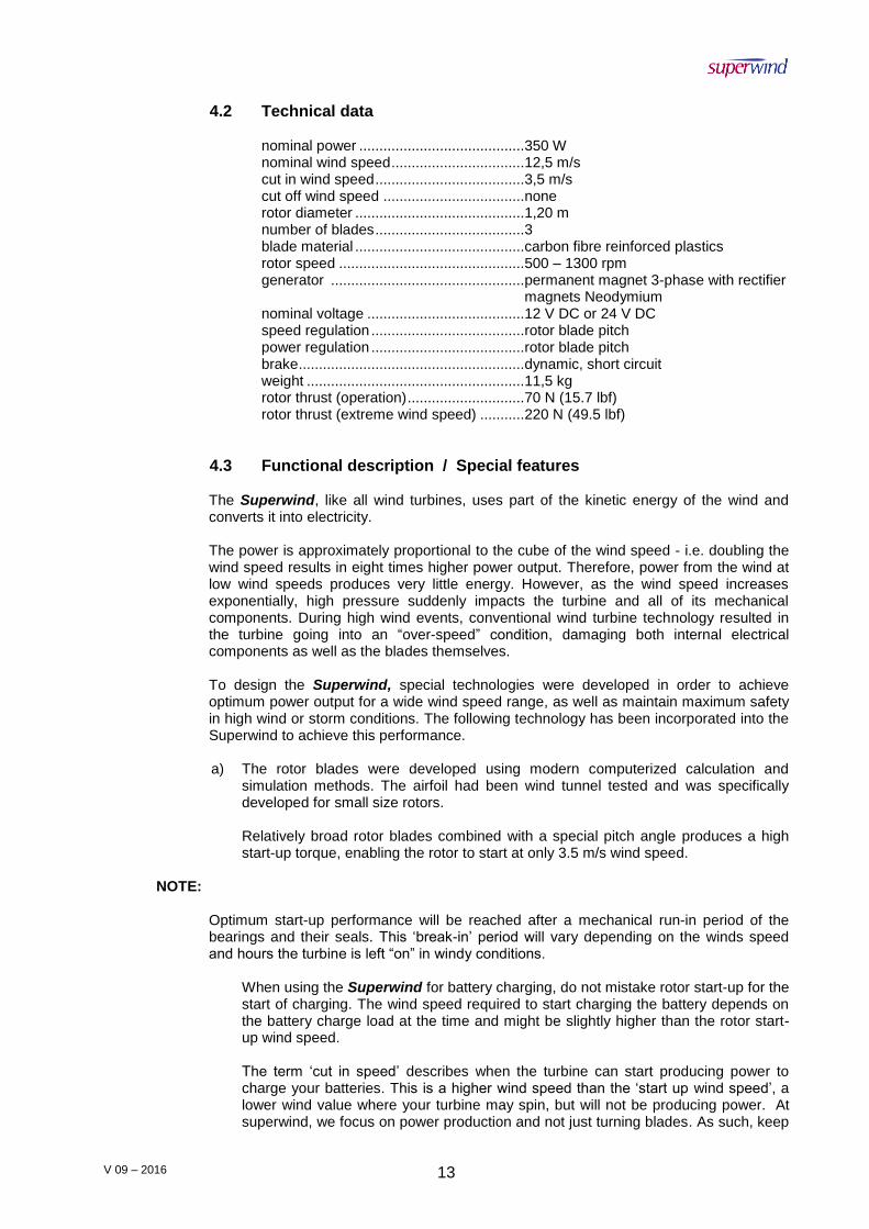
4.2 Technical data
nominal power ......................................... 350 W nominal wind speed ................................. 12,5 m/s cut in wind speed ..................................... 3,5 m/s cut off wind speed ................................... none rotor diameter .......................................... 1,20 m number of blades ..................................... 3 blade material .......................................... carbon fibre reinforced plastics rotor speed .............................................. 500 – 1300 rpm generator ................................................ permanent magnet 3-phase with rectifier magnets Neodymium nominal voltage ....................................... 12 V DC or 24 V DC speed regulation ...................................... rotor blade pitch power regulation ...................................... rotor blade pitch brake ........................................................ dynamic, short circuit weight ...................................................... 11,5 kg rotor thrust (operation) ............................. 70 N (15.7 lbf) rotor thrust (extreme wind speed) ........... 220 N (49.5 lbf)
4.3 Functional description / Special features
The Superwind, like all wind turbines, uses part of the kinetic energy of the wind and converts it into electricity. The power is approximately proportional to the cube of the wind speed - i.e. doubling the wind speed results in eight times higher power output. Therefore, power from the wind at low wind speeds produces very little energy. However, as the wind speed increases exponentially, high pressure suddenly impacts the turbine and all of its mechanical components. During high wind events, conventional wind turbine technology resulted in the turbine going into an “over-speed” condition, damaging both internal electrical components as well as the blades themselves. To design the Superwind, special technologies were developed in order to achieve optimum power output for a wide wind speed range, as well as maintain maximum safety in high wind or storm conditions. The following technology has been incorporated into the Superwind to achieve this performance.
a) The rotor blades were developed using modern computerized calculation and
simulation methods. The airfoil had been wind tunnel tested and was specifically developed for small size rotors.
Relatively broad rotor blades combined with a special pitch angle produces a high start-up torque, enabling the rotor to start at only 3.5 m/s wind speed.
NOTE:
Optimum start-up performance will be reached after a mechanical run-in period of the
bearings and their seals. This ‘break-in’ period will vary depending on the winds speed and hours the turbine is left “on” in windy conditions.
When using the Superwind for battery charging, do not mistake rotor start-up for the start of charging. The wind speed required to start charging the battery depends on the battery charge load at the time and might be slightly higher than the rotor start-up wind speed.
The term ‘cut in speed’ describes when the turbine can start producing power to charge your batteries. This is a higher wind speed than the ‘start up wind speed’, a lower wind value where your turbine may spin, but will not be producing power. At superwind, we focus on power production and not just turning blades. As such, keep
V 09 – 2016 14
in mind that the wind speed required to start charging the battery depends on the battery state of charge (load) and other basic electrical system factors.
NOTE: Your turbine has extremely high quality bearing sets to provied a long, nearly maintenance free service life. These special bearings require a “ break in period“ of weeks or possibly months to achieve the highest charging levels at lower wind speed conditions. Leaving the Superwind turbine in the autonomous “Run” position through all types of weather, including high winds and storms, will help shorten this break in period.
b) The basic innovation of Superwind is its novel aerodynamic rotor control system.
Similarly to large wind turbines, it adjusts the pitch angle of the rotor blades.
The mechanical controller is fully integrated into the hub and works without expensive electrical or hydraulic components. Instead, the controller is actuated by forces arising at operation of the wind turbine itself.
The forces are affected by the geometric and kinematic lay-out of the rotor and controller mechanism.
Aerodynamic forces act as a control variable to adjust the rotor blades for power regulation above the nominal wind speed. Centrifugal forces are the second control variable for the rotor blade adjustment. By the special arrangement of both force components, the controller limits rotor speed automatically (even at extreme wind velocities) and protects the wind turbine from over-speed, even during no-load operation. As a result, the controller limits the mechanical loads at high wind speed, providing smooth operation under all weather conditions.

V 09 – 2016 15
5. PREPARATIONS FOR ASSEMBLY
5.1 Packing list Please check your delivery for completeness and transport damage.
PACKING LIST
Table 5.1
ITEM DESCRIPTIOM SIZE QUANTITY
1 Generator unit 1
2 Hub 1
3 Wind vane 1
4 Rotor blade 3
5 Wind vane mounting plate 1
6 Plastic bushing (optional stainless steel bushing)
1
7 Socket cap screw M8 x 80 1
8 Socket cap screw M8 x 20 2
9 Socket cap screw M6 x 25 (TUFLOK) 6
10 Socket cap screw with rubber ring M6 x 8 (TUFLOK) 3
11 Hexagon socket button head screw M6 x 12 2
12 Hexagon socket button head screw M6 x 6 2
13 Allen key 6 mm 1
14 Allen key 5 mm 1
15 Allen key 4 mm 1
16 Operation’s manual 1
NOTE:
For aerodynamic reasons the rotor blades trailing edges are very thin and sharp. Use caution when unpacking, both to avoid injury and damage to the blades.
V 09 – 2016 16
5.2 Tools
A set of allen keys is included to assist with the installation of your Superwind. The following is a list of additional recommended tools:
1. screw drivers 2. set of spanners 3. wire strippers 4. wire crimpers 5. heat shrink or electrical tape 6. multimeter
For correct tightening of the screws, a torque wrench is recommended. Tools for the mast installation are not listed here. See respective instructions.
5.3 Optional accessories
Mast-sets:
Mast-set for yachts Mast-set for land installation / guyed tubular mast 6 m (other heights on request) Mast-set for land installation / self-supporting tubular mast 7,5 m
5.4 Electrical components: Charge regulator SCR Marine incl. power resistor 20 Amps (24 V System) or 40 Amps (12 V System), slow-blow fuses or breaker Fuse holder Stop-switch Ammeter
V 09 – 2016 17
6. ELECTRICAL COMPONENTS AND CONNECTIONS
6.1 General information
Ensure that any installation or repair work on the electrical system is carried out by qualified technicians only. These technicians must also read these instructions prior to starting the installation!
NOTE:
Careful pre-installation planning is a crucial first step in the installation of your new Superwind, as well as other system components that are also part of your project.
The actual electrical connection should be made during the lasts steps of the installation.
Make sure that the batteries and other charging sources (such as grid or shore power) are disconnected until the installation is complete.
6.2 Wiring diagrams 6.2.1 Recommended charge regulator
6.2.1.1 SCR Marine Charge Regulator (12V or 24V, depending on
turbine and system voltage, Graphic No. 6.2.1.1)
The SCR Marine charge regulator has been especially designed for use with the Superwind 350 wind generator. It allows the user to fully charge batteries, while also protecting battery banks from overcharging via a diversion load control, as well as temperature compensation.
Wind charge controllers are very different from solar charge controllers in that they are designed to electrically maintain the load correlation with the battery bank while simultaneously producing power above the ever changing battery state of charge. This allows the batteries to be properly charged based on ideal temperature-compensated charging rates and consumer demands.
The Diversion mode initiates when the batteries have reached their maximum charging voltage; the SCR Marine´s PWM circuit automatically diverts the wind turbine´s surplus power to the diversion resistor block. With this technology, even when batteries are fully charged, the wind turbine continues operating (provides useable power generated when there is ample wind) providing real time power to other electric consumers (loads) as they come online automatically or when switched on manually.
This ‘Diversion State’ (dumping generated power) is indicated by an LED illuminating (turning on) on the SCR Controller when the battery bank is full – indicating that electric power (above and beyond the battery bank charging needs) is available to be used rather than dumped.

V 09 – 2016 18
The SCR Marine Charge Controller is suitable for charging lead acid batteries, gel batteries and AGM batteries (AGM = Absorbed Glass Mat) and some Lithium Ion batteries (NOTE: consult your Superwind Customer Service Contact and the battery manufacturer for important specific details before trying to charge Lithium Ion Batteries!). For special applications, the maximum charging voltage can be adjusted to customer
requirements by superwind.
The SCR Marine charge regulator is completely sealed and protected against moisture (such as found in a marine environment) however it is not waterproof and should be installed in a suitable weather proof outdoor control panel or located in an appropriate dry space aboard ship.
The SCR Marine charge regulator has the ability to charge two separate battery banks independently, yet still work in diversion mode when both battery banks are in a full state of charge (eg. starter battery set and the house battery bank on a yacht).
IMPORTANT:
An advantage of using the SCR Charge Controller is that it can work alongside other charging technologies such as solar panels, diesel generators, fuel cells,

V 09 – 2016 19
engine power (from the alternator), and even shore power (aboard ship or at a site) without affecting other operations. Please contact your Superwind customer service contact for special configuration information or more details.
6.2.1.2 Diversion Load Resistor
The resistance of the cable that connects the load resistor with the charge regulator can affect the charging voltage. Therefore, the connecting resistor wire run should not exceed 1 meter with the recommended wire gauge. If you would like to extend the resistor wire beyond 1 meter, please refer to the AWG Wire Size Chart (Table No. 6.3.1.1 and 6.3.1.2).
NOTE: Charge regulators are not protected against reversed polarity of the wires (“+” & “-“), and will be damaged if connected incorrectly! Connecting the wrong wire (line) polarity to your Charge Controller will void the warranty!
Do not reverse the polarity of the wires.
If you want to use a different charge regulator than what is recommended for use with your Superwind 350 (the SCR Marine charge controller: 12v or 24v), make sure that it is a suitable shunt-regulator based device with full time diversion load control. To insure you are not voiding the warranty on your Superwind turbine, please ask your Superwind customer service contact as many other charge controllers - especially those used for solar photovoltaic systems - are unsuitable, since they interrupt the electric circuit for voltage regulation and can render the wind generator into a dangerous no-load operation!
6.3 System components
6.3.1 Wires
The cross sections (gauge) of the wires required depends on their length and the rated voltage of your wind generator. After selecting the location of the mast, measure the distance from the mast top to the battery and then select the minimum cross section required on the basis of the following tables. In order to keep the power loss of the lines as small as possible, do not use lines with under-sized cross sections.
It is always recommended to use stranded (braided) wire. Solid wire should be avoided.

V 09 – 2016 20
For the 12 Volt version:
AWG Wire Size Chart for 12 Volt Version Table No. 6.3.1.1
Distance from mast top to the battery
From: To:
up to 5,2 m
5,3 m 8,7 m
8,8 m 14 m
14,1 m 21,8 m
21,9 m 30,6 m
30,7 m 43,7 m
Minimum gauge (cross section)
6 mm² 10 mm² 16 mm² 25 mm² 35 mm² 50 mm²
Recommended per wire AWG 10 AWG 8 AWG 6 AWG 4 AWG 2 AWG 1
Refer to Graphic No. 6.3.1.2 to better understand cross section
For the 24 Volt version:
AWG Wire Size Chart for 24 Volt Version Table No. 6.3.1.2
Distance from mast top to the battery
From: To:
up to 8,7 m
8,8 – 14 m
14,1 – 21 m
21,1 – 34,9 m
35 – 55,9 m
56 – 87,3 m
Minimum gauge (cross section)
2,5 mm² 4 mm² 6 mm² 10 mm² 16 mm² 25 mm²
Recommended per wire AWG 14 AWG 12 AWG 10 AWG 8 AWG 6 AWG 4
See Graphic No. 6.3.1.2
NOTE:
The cross sections of the above two tables refer to a maximum voltage drop of 5% when
using copper wires
Installations using a smaller than recommended wire gauge can get dangerously hot, resulting in damage to the system and possibly cause an electrical fire. Plan and install your system correctly!
For applications on board a boat or in marine (i.e. salt water) environments, wiring with tinned braids is recommended, in order to prevent corrosion.

V 09 – 2016 21
If the wire is to be buried (installed underground), a special underground rated wire must be used, and / or the wire run must be led through an underground rated conduit. In all applications, ultraviolet (UV) resistant wire should be used, so that it is protected against environmental influences. The same applies to the insulation covering, including heat shrink sleeves, and electrical tape at connection points. For protection of the wire against chafing, the hole at the bottom of the mast must be properly de-burred. If necessary, install a piece of rubber tube over the wires to prevent wear from sharp metal at contact points.
For connecting to the terminals, wire ends must be stripped and suitable wire end ferrules or lugs must be crimped in place. (Graphic No. 6.3.1.4).
6.3.2 Strain Relief
Wires that connect to the turbine and travel down through the mast have weight. Depending on mast length, the length of the wire run, coupled with the selected wire size (AWG profile) can result in a significant amount of weight. This weight can cause strain on both the mast wiring connections and wires coming out of the turbine if not relieved.
It is recommended that for mobile wind turbine integrations - as well as any application with tall masts - that the wire be hung from the Strain Relief Bar located in the Yaw Shaft (Graphic No. 6.3.2.2). This is especially true if the wire hanging in the mast weighs more than 5 kg; a strain relief must be attached in the mast top or via the internal Strain Relief Bar located within the Yaw Shaft. This ensures that the internal junction point at the slip rings of your Superwind will not be damaged. The Yaw Shaft strain relief bar is composed of a cylinder pin 3 mm OD x 40 mm which is shown in the drawing in Graphic 6.3.2.2 on page 21.

V 09 – 2016 22
6.3.3 Polarity Always pay attention to the correct polarity of the lines. Connecting to the batteries with reversed polarity will destroy the electric rectifier of your Superwind. In general, you should mark all line ends by POSITIVE (+) and NEGATIVE (-), in order to prevent errors with the connection.
Marking of the connecting wires at the Superwind:
POSITIVE Line (+): RED NEGATIVE Line (-): BLACK
The internal electric rectifier of the Superwind will be destroyed by connecting the wires with reversed polarity. Loss of warranty will result!
6.3.4 Batteries 6.3.4.1 Charging batteries
The most common use of the Superwind is charging batteries. Our diversion charge regulator allows the Superwind operation to be autonomous. Autonomous operation allows the batteries to be brought to a full state of charge (SOC) and still be protected against overcharging, resulting in longer battery life and maintaining the battery manufacturer warranty. When selecting batteries, pay particular attention to the correct rated voltage (12 V or 24 V). The rated voltage of your Superwind is specified on the yaw serial number label. (See Section 1 on Page No. 5). Lead-acid batteries are most commonly used. The Superwind SCR Charge regulators (Section 6.2 on Page No. 18) are suitable for all types of batteries, although (depending on the battery manufacturing specs) the charge controller may need to be adjusted to the battery manufacturer recommendations. We recommend batteries designed for stationary use (not starting batteries). Stationary or deep cycle batteries are more suitable because they are designed for deeper discharge and rapid recharge cycling, resulting in a longer service life. Many deep cycle batteries are maintenance-free and better survive occasional deep (below manufacturer’s recommended SOC) discharges than do starter type batteries. Car batteries (starting batteries) should be avoided as house span batteries because they wear out very fast when exposed to the repeated discharge/charging cycles that will normally occur in your system. Another important criteria for battery selection is the ‘capacity’, expressed in ampere-hours (Ah). This value represents the quantity of storable energy. The required capacity depends on your individual situation (wind location, consumption structure, combination with other generators sources like diesel, solar etc.). Your battery dealer can assist you in selecting a suitable battery.
V 09 – 2016 23
When selecting battery location for an installation, refer to the battery manufacturer’s instructions. Charging lead-acid batteries produce potentially flammable hydrogen gas. Unsealed lead-acid batteries have vent holes that also release hydrogen, which forms potentially explosive gas in the surrounding environment. A small spark (e.g. an electrical switch) can detonate this explosive gas mixture. For explosion and fire prevention, always provide sufficient ventilation for your battery bank.
Never install the batteries in places with a danger of flame or spark formation.
Provide sufficient ventilation at all times.
Batteries store a large quantity of energy potential, which when suddenly discharged (in the case of a short-circuit) can destroy the battery (releasing battery acid and gas) and/or set the battery and wiring on fire! Short-circuiting wires or batteries must be avoided in all cases. For this reason battery terminal connections must only be made after all work on the electric system has been completed.
NEVER SHORT-CIRCUIT THE BATTERY.
NOTE:
The battery terminals may be connected only after all work on the electric system has been completed.
For protection against high voltage spikes and/or an accidental short-circuit event, fuses must be installed in the positive (+) wires to the battery. See Section 6.3.5 on page 25 for fuses. See Graphic 6.2.1.1 for connection diagram on page 18. Since blowing a fuse or releasing an automatic circuit breaker can cause an electrical spark, fuses and breakers must not be installed in the same area as the battery. Use extreme caution while handling battery acid, refilling with distilled water or performing other maintenance on the batteries. Follow the instructions of the battery manufacturer and wear protective clothing and suitable eye protection.
Act with extreme caution while handling battery acid. Wear protective clothing and suitable eye protection.
6.3.4.2 SCR Marine Charge Regulator (with diversion load control)
The 12 volt or 24 volt SCR Marine charge regulator has been especially designed for use with the Superwind 350 wind generator, allowing the user to fully charge batteries while also protecting battery bank from overcharging via a diversion
V 09 – 2016 24
load control, as well as temperature compensation. The SCR marine charge regulator has a self-contained temperature sensor that allows the unit to sense the proximate temperature of the controller. If the charge controller is to be installed in an area with a significantly different temperature than the battery storage area, an optional external sensor is available.
Wind charge controllers are very different from solar charge controllers in that they are designed to electrically maintain the load correlation with the battery bank while simultaneously producing power above the ever changing battery state of charge. This allows the batteries to be properly charged based on ideal temperature compensated charging rates and consumer loads. The Diversion mode engages when the batteries have reached their maximum charging voltage, and the SCR Marine´s PWM circuit automatically diverts the wind turbine´s surplus power to the diversion resistor block. With this technology, even when batteries are fully charged, the wind turbine continues operating (generating useable power when there is ample wind) providing real time power to other electric consumers (loads) when they come on automatically or are switched on manually. This ‘Diversion State of Charge’ is indicated by an LED illuminating (turning on) at the SCR Controller when the battery bank is full – indicating that electric power above and beyond the battery bank charging needs is available to be used rather than dumped.
The SCR Marine Charge Controller is suitable for charging lead acid batteries, gel batteries and AGM batteries (AGM = Absorbed Glass Mat) and some Lithium Ion batteries (NOTE: consult your Superwind Customer Service Contact and the battery manufacturer for important specific details before trying to charge Lithium Ion Batteries!). For special applications, the maximum charging voltage can be adjusted to customer requirements by superwind.
The SCR Marine charge regulator is completely sealed and effectively protected against moisture (such as in the marine environment) however it is not waterproof and should be installed in a suitable weather-proof outdoor control panel or located in an appropriate dry space aboard ship.
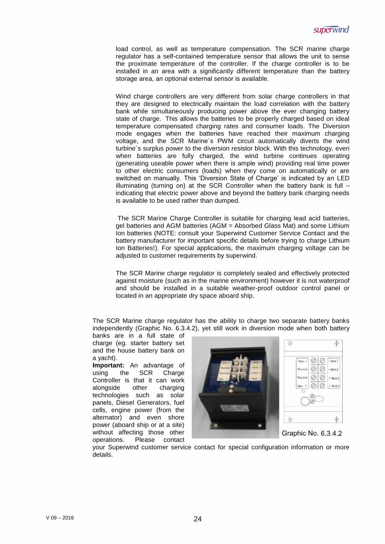
The SCR Marine charge regulator has the ability to charge two separate battery banks independently (Graphic No. 6.3.4.2), yet still work in diversion mode when both battery banks are in a full state of charge (eg. starter battery set and the house battery bank on a yacht). Important: An advantage of using the SCR Charge Controller is that it can work alongside other charging technologies such as solar panels, Diesel Generators, fuel cells, engine power (from the alternator) and even shore power (aboard ship or at a site) without affecting those other operations. Please contact your Superwind customer service contact for special configuration information or more details.

V 09 – 2016 25
The charge regulators are not protected against interchanged polarity of the lines (wires) and would be damaged in a reversed polarity situation.
If you want to use a different charge regulator other than the one described here, make sure that it is a shunt-regulator.
6.3.4.3 Diversion Load Resistor
The resistance of the cable that connects the load resistor with the charge regulator can affect the charging voltage. Therefore, the connecting resistor wire run should not exceed 1 meter with the recommended wire gauge. If you would like to extend the resistor wire beyond 1 meter, please refer to the AWG Wire Size Chart (Table No. 6.3.1.1 and 6.3.1.2).
NOTE: The series controllers (sometimes called Solar Charge Controllers/Regulators) often used in photovoltaic systems are unsuitable. They interrupt the electric circuit for voltage regulation, which would allow the wind generator to run in no-load operation. Additionally, the charge regulator must be laid out for electric flows of at least 40 A (12 V version) or 20 A (24 V version).
6.3.5 Fuses
To protect the battery against short-circuits, fuses must be installed in the POSITIVE line between the wind generator and the battery and in the POSITIVE line between the battery and the charge regulator. (See Graphic No. 6.2.1.1 on Page 18). The fuses are 40 ampere slow-blow type (12 V-system), 20 ampere slow-blow type (24 V-system), or appropriate automatic circuit breakers. Fuses must be placed as close to the battery as possible, however they cannot be installed within the same compartment. Unsealed lead-acid batteries have vent holes which release hydrogen that mixes with the ambient air to create a potentially explosive mixture. The spark generated by a blowing fuse (or release of an automatic circuit breaker) can detonate this explosive gas mixture.
6.3.6 Stop switch
Graphic No. 6.3.6
The stop switch is used to shut down the wind generator operation or to prevent starting of the rotor during maintenance, repairs, or when working in the turbine operational area.
When using the Superwind on a boat or a sailing yacht, installation of a stop switch is strongly recommended to
V 09 – 2016 26
shut the wind turbine down in heavy weather at sea. Spray and waves, parts detached from the rigs or from the sails or other equipment could strike and damage the spinning rotor. Reduced mobility under such conditions could also increase the risk of accidental contact with the spinning rotor by personnel
If you run the system without a charge regulator (Not Recommended!) a stop switch is mandatory and in this case the battery’s state of charge must be continuously supervised by the operator and stopped when the battery is fully charged or if the system is going to be left unattended for any reason. The stop switch disconnects the Superwind from the battery and simultaneously shuts down the rotor. The stop switch must be installed in the line between the wind generator and the battery as close to the wind generator as possible (see Wiring Diagrams in Section 6.2.1.1 on Page 18).
NEVER PUT A CIRCUIT BREAKER OR FUSE BETWEEN THE STOP SWITCH AND THE WIND TURBINE.
The stop switch has two positions:
a) RUN The positive wire from the generator is connected to the battery. The negative wire from the generator is connected to the battery.
b) STOP The positive and the negative wires from the wind generator are short-circuited (generator short-circuit brakes the rotor). The
positive and the negative lines from the battery are both open and disconnected from the wind generator.
For further information concerning the connection of the stop switch refer to the respective installation manual.
ONLY USE A STOP SWITCH PROVIDED BY SUPERWIND! SUPERWIND SPECIFICATIONS REQUIRE THE BATTERY
TO BE DISCONNECTED AND NOT SHORT-CIRCUITED WHEN THE SWITCH IS OPERATED.
6.4 Grounding In order to protect your system against damage by lightning or over voltage, it should be properly grounded. The design of the grounding system depends on the local conditions, place of installation, type of soil, groundwater table, or the availability of a pre-existing grounding bus. If you are in doubt, consult an experienced electrician or an electrical systems technician. When installing the Superwind on a yacht we recommend connecting the mast or support to the ship´s grounding system whenever possible.

V 09 – 2016 27
7. SUPERWIND 350 GENERATOR ASSEMBLY
7.1 Precautions during the mounting
Before starting the installation of your wind generator, please keep in mind the potential dangers and proceed with caution. Only use a mast and a support construction capable of safely withstanding the loads of your wind generator. The mast not only has to withstand the weight of the wind generator and its mass moment of inertia (e.g. on a sailing yacht) but also the considerable thrust caused by high wind speed. The maximum wind thrust by wind during operation will be approx. 70 N (15.7 lbf). In an extreme gust (wind speed of 49 m/s) the thrust can rise up to 220 N (49.5 lbf).
Only work on the mast or your wind generator on a calm, windless day.
Do not step or stand under hanging loads (e.g. a tilted mast) and prevent other personnel from doing so.
Make sure that batteries are disconnected from the system during all work.
TO PREVENT THE GENERATOR FROM UNINTENDED STARTING, “SHORT-CIRCUIT” THE GENERATOR BY CONNECTING THE TWO GENERATOR CABLES TOGETHER. Graphic No. 7.1.1 IF THE WIRE RUN – INCLUDING STOP SWITCH – IS ALREADY INSTALLED, THE STOP SWITCH CAN BE PLACED IN THE ‘STOP’ POSITION FOR THE SAME PURPOSE AS GRAPHIC NO.7.1.1
DISCONNECT THE BATTERY BEFORE SHORTING THE TWO CABLES TOGETHER!
Do not approach a spinning rotor. Never try to stop the rotor by hand. Never tie any blade to the mast - the aerodynamic design
will be distorted and/or damaged and will affect the performance of the turbine.
Do not install the wind generator where personnel could come into contact with the rotor.
V 09 – 2016 28
7.2 Mast mounting
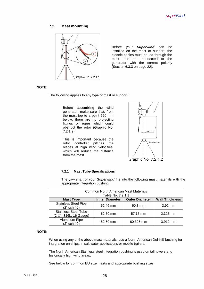
Before your Superwind can be installed on the mast or support, the electric cables must be led through the mast tube and connected to the generator with the correct polarity (Section 6.3.3 on page 22).
NOTE:
The following applies to any type of mast or support:
Before assembling the wind generator, make sure that, from the mast top to a point 650 mm below, there are no projecting fittings or ropes which could obstruct the rotor (Graphic No. 7.2.1.2).
This is important because the rotor controller pitches the blades at high wind velocities, which will reduce the distance from the mast.
7.2.1 Mast Tube Specifications
The yaw shaft of your Superwind fits into the following mast materials with the appropriate integration bushing:
Common North American Mast Materials Table No. 7.2.1.1
Mast Type Inner Diameter Outer Diameter Wall Thickness
Stainless Steel Pipe (2” sch 40)
52.46 mm 60.3 mm 3.92 mm
Stainless Steel Tube (2 ¼”, 316L, 16 Gauge)
52.50 mm 57.15 mm 2.325 mm
Aluminum Pipe (2” sch 40)
52.50 mm 60.325 mm 3.912 mm
NOTE:
When using any of the above mast materials, use a North American Delrin® bushing for integration on ships, in salt water applications or mobile trailers. The North American Stainless steel integration bushing is used on tall towers and historically high wind areas. See below for common EU size masts and appropriate bushing sizes.

V 09 – 2016 29
North American Delrin® bushing specification fits pipe with an ID ranging from 2.05” – 2.15” (this bushing OD is 2.16” and can be sanded down to spec). North American Stainless Steel bushing – use only on high towers or in higher than average wind areas; not aboard ships. This bushing cannot be sanded, and is specified for immediate use.
Bushings Table No. 7.2.1.3
BUSHING TYPE INNER DIAMETER OUTER DIAMETER
North American Stainless Steel
mm inches mm inches
42.2 1.66 52.1 2.05
North American Delrin®
44.2 1.74 47.9 52.9
2.08
EU Delrin®
44.2 1.74 Bands
56 2.2
No bands
54.6 2.15
7.2.2 Mounting the Turbine on the Mast
With welded tubes, ensure that the welding seam does not obstruct the insertion of the yaw shaft. If necessary, an out-standing seam must be smoothed with a round file or the like. 7.2.3 Preparations at the mast head: Deburr or smooth the end of the tube carefully (inside and outside).File off the welding seam if necessary. Drill the two holes 7 mm (distance to the mast top: 35 mm) Graphic No. 7.2.2.3 on Page 30. The included plastic (Delrin®) bushing needs to be mounted onto the yaw shaft of the generator unit. The two elastomer damping rings of the yaw shaft as well as the inner surface of the plastic bushing have to be lubricated with Vaseline®. Graphic No. 7.2.2.1 (showing North American Delrin® bushing). Be careful not to damage the damping rings while pushing the yaw shaft into the plastic bushing. (Graphic No. 7.2.2.1)
Before the plastic bushing is installed on the yaw shaft, align the three 16 mm holes of the bushing concentrically with the respective threads M6 of the yaw shaft. Now push the plastic bushing with the collar ahead onto the elastomer damping rings to the limit stop at the O-ring seal 40x3. Be careful not to damage the damping rings during installation. Next, screw the three socket cap screws (M6 x 8) together with the rubber rings on their head in each of the threads. These bolts have a TUFLOK (blue color)
V 09 – 2016 30
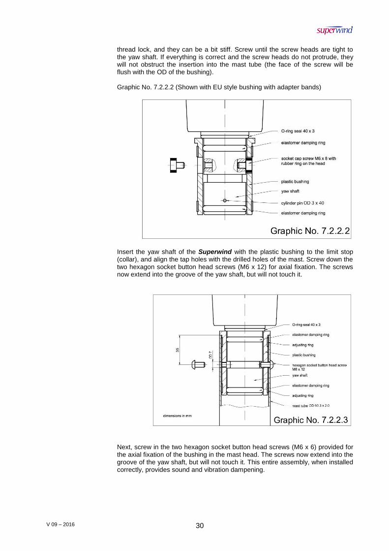
thread lock, and they can be a bit stiff. Screw until the screw heads are tight to the yaw shaft. If everything is correct and the screw heads do not protrude, they will not obstruct the insertion into the mast tube (the face of the screw will be flush with the OD of the bushing).
Graphic No. 7.2.2.2 (Shown with EU style bushing with adapter bands)
Insert the yaw shaft of the Superwind with the plastic bushing to the limit stop (collar), and align the tap holes with the drilled holes of the mast. Screw down the two hexagon socket button head screws (M6 x 12) for axial fixation. The screws now extend into the groove of the yaw shaft, but will not touch it.
Next, screw in the two hexagon socket button head screws (M6 x 6) provided for the axial fixation of the bushing in the mast head. The screws now extend into the groove of the yaw shaft, but will not touch it. This entire assembly, when installed correctly, provides sound and vibration dampening.

V 09 – 2016 31
7.3 Mounting of the wind vane
The wind vane is fastened to the rear cover of the generator. Insert the wind vane and the mounting plate into the groove. As viewed from the rear (Graphic No. 7.3), the mounting sheet must be on the right side. Next, insert the two socket cap screws M8 x 20 and screw them down firmly.
7.4 Rotor assembly There are two methods to assemble the rotor of your Superwind: a) The hub is attached to the generator shaft and the rotor blades are fitted to the hub
later. b) The rotor blades are fitted to the hub first, and then the completed rotor is attached
to the generator. We recommend method b) since in most cases it is easier to assemble the rotor completely at a convenient place and take it to the wind generator for attachment afterwards.
7.4.1 Rotor Blade Hub Assembly
NOTE:
For aerodynamic reasons the rotor blades trailing edges are very thin and sharp. Use care when unpacking the blades to avoid injury.
Superwind rotor blades are manufactured as sets of three, balanced by weight and axial runout. These 3 blades can be fixed to the hub in any order. However, do not mix and match blades from different Superwind 350 blades sets as this could
V 09 – 2016 32
cause the rotor to become out of balance. This means that if a single Superwind 350 blade is damaged, the entire blade set needs to be replaced - not just one blade.
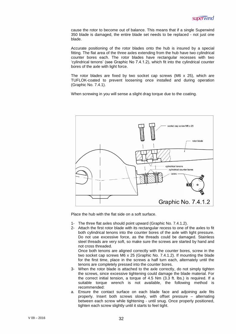
Accurate positioning of the rotor blades onto the hub is insured by a special fitting. The flat area of the three axles extending from the hub have two cylindrical counter bores each. The rotor blades have rectangular recesses with two ‘cylindrical tenons’ (see Graphic No 7.4.1.2), which fit into the cylindrical counter bores of the axle with light force.
The rotor blades are fixed by two socket cap screws (M6 x 25), which are TUFLOK-coated to prevent loosening once installed and during operation (Graphic No. 7.4.1). When screwing in you will sense a slight drag torque due to the coating.
Place the hub with the flat side on a soft surface.
1- The three flat axles should point upward (Graphic No. 7.4.1.2). 2- Attach the first rotor blade with its rectangular recess to one of the axles to fit
both cylindrical tenons into the counter bores of the axle with light pressure. Do not use excessive force, as the threads could be damaged. Stainless steel threads are very soft, so make sure the screws are started by hand and not cross threaded. Once both tenons are aligned correctly with the counter bores, screw in the two socket cap screws M6 x 25 (Graphic No. 7.4.1.2). If mounting the blade for the first time, place in the screws a half turn each, alternately until the tenons are completely pressed into the counter bores.
3- When the rotor blade is attached to the axle correctly, do not simply tighten the screws, since excessive tightening could damage the blade material. For the correct initial tension, a torque of 4.5 Nm (3.3 ft. lbs.) is required. If a suitable torque wrench is not available, the following method is recommended:
a. Ensure the contact surface on each blade face and adjoining axle fits properly. Insert both screws slowly, with offset pressure – alternating between each screw while tightening - until snug. Once properly positioned, tighten each screw slightly until it starts to feel tight.

V 09 – 2016 33
b. At this point, screw down exactly one quarter turn in order to adjust to the correct final tension.
c. Continue mounting the other two blades the same way. NOTE:
Make sure, that the cylindrical tenons on each blades are correctly inserted into the
axles counter bores. Do not use force. Do not over-tighten the screws.
7.4.2 Mounting the hub to the generator shaft
NOTE:
In order to prevent the rotor from unintended starting, it is recommended to short circuit the two generator cables (See Graphic No. 7.1.1 on Page No. 27) or turn your stop switch into STOP position before beginning with the assembling.
DISCONNECT THE BATTERIES BEFOREHAND!
Once the rotor hub blade assembly has been completed, align the center to the generator (paying close attention to the alignment with the keyed generator shaft) and connect the hub to the generator.
NOTE:
Remember to hold the rotor at the hub only (not by the blades) as the sharp edges of the rotor blades could cause injuries or the blades could be damaged.
V 09 – 2016 34
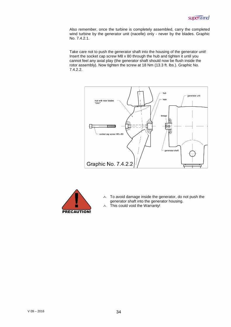
Also remember, once the turbine is completely assembled, carry the completed wind turbine by the generator unit (nacelle) only - never by the blades. Graphic No. 7.4.2.1.
Take care not to push the generator shaft into the housing of the generator unit! Insert the socket cap screw M8 x 80 through the hub and tighten it until you cannot feel any axial play (the generator shaft should now be flush inside the rotor assembly). Now tighten the screw at 18 Nm (13.3 ft. lbs.). Graphic No. 7.4.2.2.
To avoid damage inside the generator, do not push the generator shaft into the generator housing.
This could void the Warranty!
V 09 – 2016 35
8. COMMISSIONING
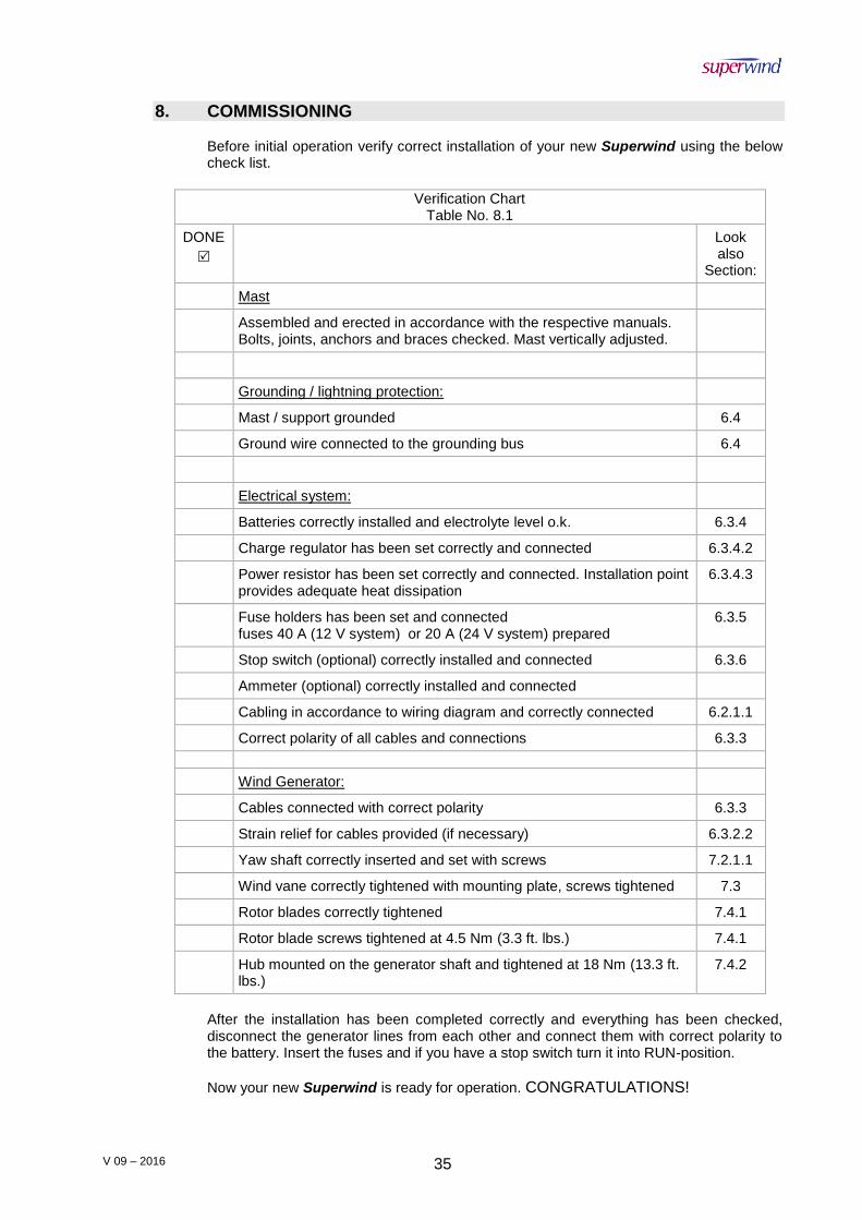
Before initial operation verify correct installation of your new Superwind using the below check list.
Verification Chart
Table No. 8.1
DONE
Look also
Section:
Mast
Assembled and erected in accordance with the respective manuals. Bolts, joints, anchors and braces checked. Mast vertically adjusted.
Grounding / lightning protection:
Mast / support grounded 6.4
Ground wire connected to the grounding bus 6.4
Electrical system:
Batteries correctly installed and electrolyte level o.k. 6.3.4
Charge regulator has been set correctly and connected 6.3.4.2
Power resistor has been set correctly and connected. Installation point provides adequate heat dissipation
6.3.4.3
Fuse holders has been set and connected fuses 40 A (12 V system) or 20 A (24 V system) prepared
6.3.5
Stop switch (optional) correctly installed and connected 6.3.6
Ammeter (optional) correctly installed and connected
Cabling in accordance to wiring diagram and correctly connected 6.2.1.1
Correct polarity of all cables and connections 6.3.3
Wind Generator:
Cables connected with correct polarity 6.3.3
Strain relief for cables provided (if necessary) 6.3.2.2
Yaw shaft correctly inserted and set with screws 7.2.1.1
Wind vane correctly tightened with mounting plate, screws tightened 7.3
Rotor blades correctly tightened 7.4.1
Rotor blade screws tightened at 4.5 Nm (3.3 ft. lbs.) 7.4.1
Hub mounted on the generator shaft and tightened at 18 Nm (13.3 ft. lbs.)
7.4.2
After the installation has been completed correctly and everything has been checked, disconnect the generator lines from each other and connect them with correct polarity to the battery. Insert the fuses and if you have a stop switch turn it into RUN-position.
Now your new Superwind is ready for operation. CONGRATULATIONS!

V 09 – 2016 36
9. OPERATION
9.1 Safety instructions
Do not run your Superwind unless you have confirmed that no persons can touch the spinning rotor.
Do not run your Superwind without an electrical load. (e.g. no load connected at
all or battery fully charged without charge regulator connected).
9.2 RUN and STOP
NOTE:
RUN (autonomous operation – making power when there is wind or waiting for wind to start).
STOP (Shut-down)
The Superwind turbine is designed for unattended automatic operation (autonomous use) in all weather conditions. Nevertheless, there might be situations when you would like to stop it. For that purpose, the use of a stop switch is recommended. See Section 6.3.6 on Page 26
For wiring, see Section 6.3.1 on page 20 In RUN-position, the wind generator supplies power to the battery and to the appliances connected to it when there is sufficient wind power. By manually turning the safety switch to the STOP-position, the wind generator will be disconnected from the battery and the generator output wires will be short-circuited simultaneously. The generator short circuit also prevents the rotor from turning at operational speeds. NOTE: In very high wind conditions the rotor may not stop completely, but will continue running at very low revolutions and will still be disconnected from the battery completely.
Never try to stop the spinning rotor by hand. Even slowed down by the stop switch, the slowly running rotor can cause serious injuries.
If there is no stop switch wired, the only way to slow down your Superwind is to disconnect the generator from the battery and then connect the generator leads to each other.
(Short Circuit Section 7.1 on Page 27) Be extremely careful to avoid short- circuiting the battery by mistake.
9.3 Power control
As described earlier in Section 4.3.b (Page 14) the Superwind is equipped with a unique aerodynamic, feathering rotor control system. This over-speed control also helps ensure known electrical output in high wind speeds, adding to the unit’s autonomous operation and safety.
V 09 – 2016 37
Function:
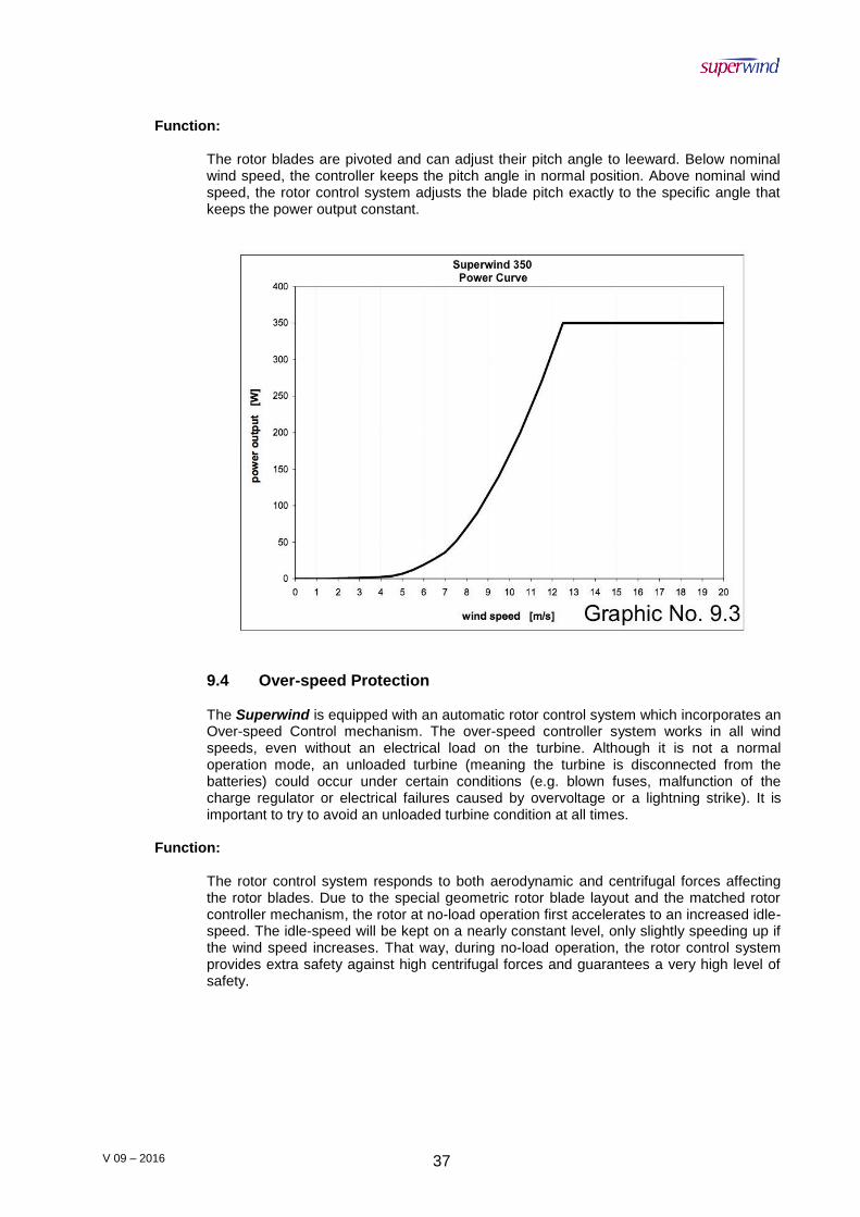
The rotor blades are pivoted and can adjust their pitch angle to leeward. Below nominal wind speed, the controller keeps the pitch angle in normal position. Above nominal wind speed, the rotor control system adjusts the blade pitch exactly to the specific angle that keeps the power output constant.
9.4 Over-speed Protection
The Superwind is equipped with an automatic rotor control system which incorporates an Over-speed Control mechanism. The over-speed controller system works in all wind speeds, even without an electrical load on the turbine. Although it is not a normal operation mode, an unloaded turbine (meaning the turbine is disconnected from the batteries) could occur under certain conditions (e.g. blown fuses, malfunction of the charge regulator or electrical failures caused by overvoltage or a lightning strike). It is important to try to avoid an unloaded turbine condition at all times.
Function: The rotor control system responds to both aerodynamic and centrifugal forces affecting the rotor blades. Due to the special geometric rotor blade layout and the matched rotor controller mechanism, the rotor at no-load operation first accelerates to an increased idle-speed. The idle-speed will be kept on a nearly constant level, only slightly speeding up if the wind speed increases. That way, during no-load operation, the rotor control system provides extra safety against high centrifugal forces and guarantees a very high level of safety.

V 09 – 2016 38
9.5 Annual power production
In DC-systems, the electrical power is the product of voltage and current. Actual output, however, is a function of the generator speed and the load connected, including the battery state of charge (i.e. the electric resistance of the consumers, including the battery). Therefore, the actual annual power produced is a function of the wind conditions at your site, in combination with what is being powered and/or the battery bank being charged. The diagram below shows the annual power production versus Rayleigh distributed annual mean wind speeds.
V 09 – 2016 39
10. INSPECTIONS, MAINTENANCE
10.1 Periodic inspections
Your Superwind has been designed to run for years without maintenance, but simple periodic inspections are required for reliability, safety and peace of mind. Before performing any inspection, disconnect the Superwind from the batteries and shut down the rotor as described in Section 9.2 on Page 37.
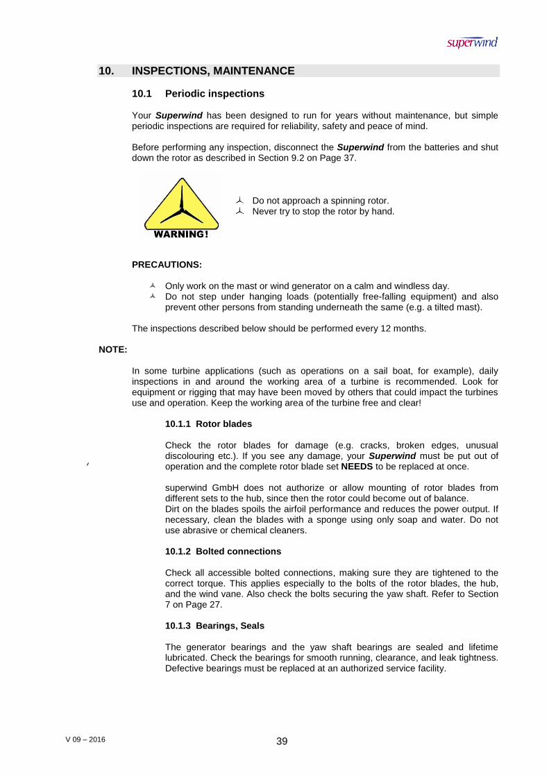
Do not approach a spinning rotor. Never try to stop the rotor by hand.
PRECAUTIONS:
Only work on the mast or wind generator on a calm and windless day. Do not step under hanging loads (potentially free-falling equipment) and also
prevent other persons from standing underneath the same (e.g. a tilted mast). The inspections described below should be performed every 12 months.
NOTE:
In some turbine applications (such as operations on a sail boat, for example), daily inspections in and around the working area of a turbine is recommended. Look for equipment or rigging that may have been moved by others that could impact the turbines use and operation. Keep the working area of the turbine free and clear!
10.1.1 Rotor blades
Check the rotor blades for damage (e.g. cracks, broken edges, unusual discolouring etc.). If you see any damage, your Superwind must be put out of operation and the complete rotor blade set NEEDS to be replaced at once. superwind GmbH does not authorize or allow mounting of rotor blades from different sets to the hub, since then the rotor could become out of balance. Dirt on the blades spoils the airfoil performance and reduces the power output. If necessary, clean the blades with a sponge using only soap and water. Do not use abrasive or chemical cleaners.
10.1.2 Bolted connections Check all accessible bolted connections, making sure they are tightened to the correct torque. This applies especially to the bolts of the rotor blades, the hub, and the wind vane. Also check the bolts securing the yaw shaft. Refer to Section 7 on Page 27.
10.1.3 Bearings, Seals The generator bearings and the yaw shaft bearings are sealed and lifetime lubricated. Check the bearings for smooth running, clearance, and leak tightness. Defective bearings must be replaced at an authorized service facility.
V 09 – 2016 40
10.1.4 Slip rings
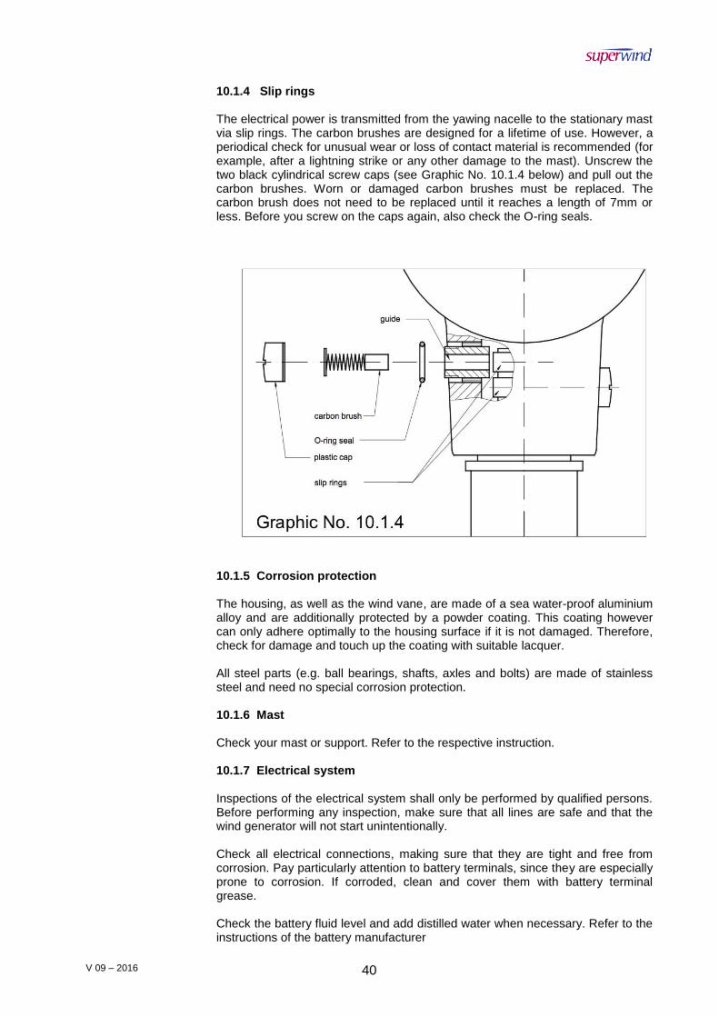
The electrical power is transmitted from the yawing nacelle to the stationary mast via slip rings. The carbon brushes are designed for a lifetime of use. However, a periodical check for unusual wear or loss of contact material is recommended (for example, after a lightning strike or any other damage to the mast). Unscrew the two black cylindrical screw caps (see Graphic No. 10.1.4 below) and pull out the carbon brushes. Worn or damaged carbon brushes must be replaced. The carbon brush does not need to be replaced until it reaches a length of 7mm or less. Before you screw on the caps again, also check the O-ring seals.
10.1.5 Corrosion protection The housing, as well as the wind vane, are made of a sea water-proof aluminium alloy and are additionally protected by a powder coating. This coating however can only adhere optimally to the housing surface if it is not damaged. Therefore, check for damage and touch up the coating with suitable lacquer. All steel parts (e.g. ball bearings, shafts, axles and bolts) are made of stainless steel and need no special corrosion protection.
10.1.6 Mast Check your mast or support. Refer to the respective instruction. 10.1.7 Electrical system Inspections of the electrical system shall only be performed by qualified persons. Before performing any inspection, make sure that all lines are safe and that the wind generator will not start unintentionally. Check all electrical connections, making sure that they are tight and free from corrosion. Pay particularly attention to battery terminals, since they are especially prone to corrosion. If corroded, clean and cover them with battery terminal grease. Check the battery fluid level and add distilled water when necessary. Refer to the instructions of the battery manufacturer

V 09 – 2016 41
10.2 Maintenance There is no special maintenance required however the periodic inspections noted previously must be performed every 12 months.

V 09 – 2016 42
11. TROUBLESHOOTING If problems occur after installation of your new Superwind, most can be solved using the below troubleshooting list. At all times be aware of electrical and mechanical hazards:
Do not approach a spinning rotor. Never try to stop the rotor by hand.
Be careful when doing work on the electrical system, since most of the lines are live.
Never short-circuit the batteries.
Useful tools for troubleshooting are:
A multimeter (voltage, current, electrical resistance) and
An anemometer (wind speed).
11.1 Wind generator does not start
Wind generator does not start
Table 11.1
Possible source of errors
Test Solution
Not enough wind Measure wind speed
Wait for more wind.
Annotation: start-up wind speed 3,5 m/s (during running-in period slightly higher)
Stop switch in STOP position
Switch to RUN
Wrong connection of the stop switch
Check stop switch and connection
Connect correctly
Debris between generator housing and hub
Find the debris Remove the hub from the generator shaft and eliminate debris

V 09 – 2016 43
Generator shaft is stiff
Turn generator shaft by hand. For this test the generator must not be short-circuited (turned off)
Repair by authorized service station
Yaw bearing is stiff, wind generator does not follow the wind direction
Move by hand Repair by authorized service station
11.2 No power output
No power output
Table 11.2
Possible source
of errors Test Solution
Not enough wind Measure wind speed
Wait for more wind
Annotation: Charging possibly will start only with 4,5 to 5,5 m/s. (depending on the battery state of charge)
Current linkage is interrupted
Check the cabling Replace defective line or devices
Fuse is blown Check the fuse Replace the fuse
Carbon brushes are without contact
Check the carbon brushes and the springs
Replace the carbon brushes
Build-in rectifier is defective
No increased torque sensible when generator cables have been short-circuited.
Repair by authorized service station
11.3 Insufficient power output
Insufficient power output
Table 11.3
Possible source of errors
Test Solution
Bad electrical connection
Measure the electric resistance of the cabling and devices
Replace defective lines or devices, clean connectors and terminals
Cable resistance too high
Check the cable cross sections and cable lengths
Use cables with higher cross sections

V 09 – 2016 44
11.4 Battery is not fully charged
Battery is not fully charged
Table 11.4
Possible source of errors
Test Solution
Battery is too old or defective
Check fluid level Fill up with distilled water, replace defective battery
Fuse is blown Check the fuse(s) Replace the fuse
Charge regulator is not connected correctly
Check connection referring to the wiring diagram
Connect the charge regulator correctly
Charge regulator defective
For troubleshooting see respective manual
Repair by authorized service station
11.5 Checking the open circuit voltage
A simple test to detect an internal defect of the generator is measuring the open circuit voltage. Disconnect the cables from the generator and connect a voltmeter to the positive and negative line. To avoid injury, dismantle the rotor blades beforehand. Now turn the hub by hand. Count the revolutions within a certain period (e.g. 30 revs within 10 seconds = 180 rpm). Watch the voltage. The voltage and the speed should correspond to the following diagram:

V 09 – 2016 45
12. REPAIRS, SPARE PARTS
12.1 Repairs If your Superwind should be defective, you may replace all parts accessible from the outside by yourself (e.g. rotor blades, carbon brushes, damping rings). In case of any other defects, please consult your dealer, an authorized service partner, or the manufacturer.
Do not open the hub housing
The hub is a safety relevant component. For repair, specialized knowledge and tools are
required. To ensure safe operation, repairs of the hub may only be performed by authorized service partners or by the manufacturer.
12.2 Spare parts list
Spare Parts Table No. 12.2
Item No
Description Part No.
1 set of rotor blades incl. socket cap screw M6 x 25 TUFLOK 0300.05.00.00
2 set of carbon brushes incl. screw caps 0300.01.03.03
3 rectifier (incl. capacitors) 0300.01.04.01
4 generator bearing front 0300.03.02.03
5 generator bearing rear 0300.03.02.04
6 set of damping rings incl. O-ring 40 x 3 0300.02.01.02
7 socket cap screw M8 x 80 V4A DIN 912 0300.04.01.10
8 hexagon socket button head screw M6 x 6 V4A ISO 7380 0300.02.01.12
9 hexagon socket button head screw M6 x 12 V4A ISO 7380 0300.02.01.10

V 09 – 2016 46
13. FREQUENTLY ASKED QUESTIONS
13.1 Basic use
Q. Can I mount a wind turbine on top my house?
A. The Superwind 350 is not for residential, grid-tied applications. This unit
was designed to charge batteries in off-grid environments only.
In situations where sufficient wind exists - such as farms, cabins, structures on cliff edges, bluffs, or near the ocean – the Superwind 350 can be an asset.
Unless architecturally engineered to be part of the structure, no wind turbine should be mounted to the roof of a house.
Q. Other than sailboats, what is the Superwind 350 used for?
A. The Superwind 350 was designed to be a commercial-grade micro wind generator that has the ability to withstand extreme environmental conditions for many years. Its applications are numerous, and it has been successfully utilized by governments, militaries, disaster preparedness & response agencies, aquaculture, and agriculture industries throughout the world.
Q. Is my boat large enough for a Superwind 350?
A. It is recommended that a Superwind 350 be mounted on a boat 30’ or
larger.
13.2 Installation
Q. How large should my battery bank be?
A. Battery capacity specifications are unique to each individual situation, and therefore cannot be easily determined by Superwind without more details. However, even the smallest battery banks that work efficiently with our turbines typically consist of a minimum of 400Ah (3-4 large batteries).
Q. Do I need a charge controller, stop-switch, and resistor?
A. It is highly recommended that a charge controller be installed to protect your batteries and turbine. A diversion load resistor (part of the Superwind charge controlling system) will shed excess loads to avoid overcharging when the batteries are completely full. The safety-stop switch will allow you to be able to safely perform maintenance near or around your unit.
The use of a Superwind 12V or 24V SRC marine charge controller is what enables your system to be completely autonomous and helps ensure full state of charge and long battery life.
Q. What size wire do I run to the Superwind and the charge controller?
A. The Superwind manual specifies wire sizing for various distances (the wire run). The proper wire size is important to optimize charging and eliminate the risk of fire. Refer to page 20 -21 for wiring specifications. Please do not hesitate to contact us for recommendations regarding your specific project.

V 09 – 2016 47
Q. Can I hook up to my hot water tank and avoid overcharging?
A. The internal electrical components in hot water tanks will not withstand overcharging, and will fail. This will, in turn, shed power to your batteries, which can be very dangerous. Your water tank was not designed as a diversion load, but our commercial resistor is.
13.3 Operation
Q. Can the Superwind be left ON while unattended (when I am not on my boat)?
A. The Superwind 350 kit (in 12V or 24V) allows for safe autonomous operation 24/7 when installed properly with the SRC marine charge controller and diversion load resistor (included in the kit).
The Superwind 350 is a commercial turbine designed for off-grid use in remote areas. When installed properly, it is maintenance-free and can be left unattended. While you can always use the safety-stop switch to temporarily shut down the unit, it is not required.
Q. Do I need to tie down the Superwind in high winds or storms?
A. No. Tying down a Superwind 350 blade or vane can actually damage the unit. You can, however, choose to utilize the safety-stop switch to enable the dynamic (magnetic) brake. The Superwind 350 is designed to operate in wind conditions nearing hurricane force speeds. In most circumstances, the unit can be left on without endangering the turbine or the batteries.
Q. How long do the bearings last?
A. The Superwind 350 ‘auto-feathers’ during high wind conditions, which prevents over speed of the turbine and lessens the wear on the bearings. This technology allows Superwind units to have a long life – many have been in the field for over a decade and are still going strong.
Q. If one blade breaks do I replace just one?
A. Superwind rotor blades are manufactured as sets of three balanced by weight and axial runout. These 3 blades can be fixed to the hub in any order. However, do not mix and match blades from different Superwind blades sets as this could cause the rotor to be out of balance. This means that if a single Superwind blade is damaged, the entire blade set needs to be replaced - not just one blade.
13.4 Troubleshooting
Q. The Superwind 350 is not producing power.
A. A common installation oversight preventing power production is related to the safety-stop switch. Ensure all screws on the safety-stop switch are tightened down securely – even the screws that are not in use. Loose screws can prevent a closed circuit, and deny power throughout the system. Refer to the manual for specific stop-switch procedures, if necessary. Again, two of the screws with no

V 09 – 2016 48
wire attached are actually forming a jumper within the switch; ensure they are tight.
Q. How can I test to ensure the Superwind unit is producing power?
A. A clamp-on DC amp meter is an inexpensive tool that can be used to test the power output from the unit. Make sure the amp meter that you purchase is capable of reading DC amps.
If the batteries are fully charged and the unit is still working in efficient wind, the charge controller will display an indicator light. When lit, a solid LED light represents a full state of charge and indicates power is being diverted to the resistor.
The use of calibrated shunts – when in combination with other charging sources - is NOT recommended for monitoring power output from the wind turbine. Calibrated shunts often negatively affect the charge controller, causing significantly reduced charging and incorrect readings. An amp coil sensor (often an option with many battery monitoring systems) is recommended instead.
Q. The Superwind 350 is not producing the expected power
A. The Superwind 350 turbine has extremely high quality bearing sets to allow for a long, nearly maintenance free, service life. These special bearings do require some weeks or months of a “break in period” to achieve the highest charging levels at lower wind speed conditions. Leaving the Superwind turbine in the autonomous “Run” position through all types of weather, including high winds and storms, will help shorten this break in period.
Please read safety-switch notation above
Do you have a calibrated shunt in your system? If yes, please read troubleshooting step above.
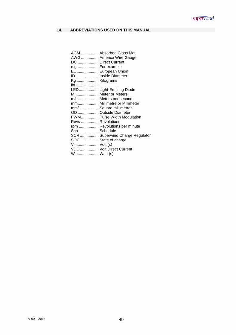
V 09 – 2016 49
14. ABBREVIATIONS USED ON THIS MANUAL
AGM ................ Absorbed Glass Mat AWG ................ America Wire Gauge DC ................... Direct Current e.g. ................... For example EU .................... European Union ID ..................... Inside Diameter Kg .................... Kilograms
lbf ..................... LED .................. Light-Emitting Diode M ...................... Meter or Meters m/s ................... Meters per second mm ................... Millimetre or Millimeter mm2 ................. Square millimetres OD ................... Outside Diameter PWM ................ Pulse Width Modulation Revs ................ Revolutions rpm .................. Revolutions per minute Sch .................. Schedule SCR ................. Superwind Charge Regulator SOC ................. State of charge V ...................... Volt (s) VDC ................. Volt Direct Current W ..................... Watt (s)
V 09 – 2016 50
Attachment A Stop-Switch Mounting Guidelines
09-2016

V 09 – 2016 51
INSTALLATION
PLEASE DO NOT PROCEED UNTIL YOU HAVE READ
ALL INSTRUCTIONS AND
SAFETY INFORMATION
© 2016 superwind GmbH. Superwind is a Registered Trade Mark of superwind GmbH, Germany
MANUAL VERSION 09-2016

V 09 – 2016 52
1. GENERAL INFORMATION
1.2 General Information
In stop-position, the switch connects the wires (+) and (-) of your Superwind 350 to short-circuit its generator to effect substantial reduction of the rotor speed. In stop-position, the switch also disconnects the shorted generator from the battery circuit.
1.2 Mounting
The stop-switch is only designed for indoor panel mounting. For easy adaption to panels up to 22 mm thickness, the shaft is adjustable. Before installing the switch, adjust the shaft to the length required and fix it by means of the screw (see picture). Note: For very thin panels, it might be necessary to cut off the screw’s head afterwards for proper mounting.
1.3 Electrical Connection
Any electrical work may be accomplished only by authorize and skilled persons!
During any connection work, the related electrical circuit must be disconnected from the battery terminals!
For optimum brake efficiency, the wires between the Superwind generator and the stop-switch should be as short as possible. For appropriate conductor cross-section, see owner’s manual.
It is obligatory to install a fuse of 40 A in the (+) wire between the stop-switch and the battery!
No fuse must be installed between the stop-switch and the Superwind generator!
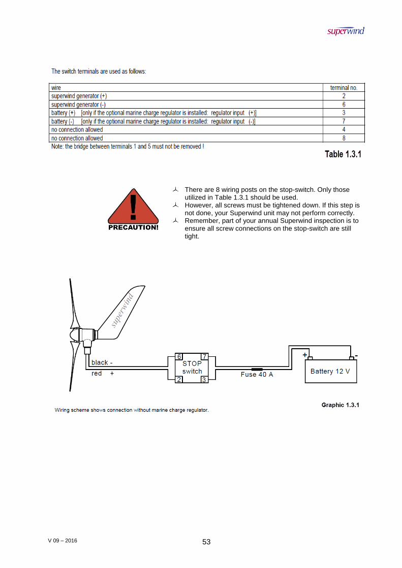
V 09 – 2016 53
There are 8 wiring posts on the stop-switch. Only those utilized in Table 1.3.1 should be used.
However, all screws must be tightened down. If this step is not done, your Superwind unit may not perform correctly.
Remember, part of your annual Superwind inspection is to ensure all screw connections on the stop-switch are still tight.

V 09 – 2016 54
Attachment B Superwind Charge Regulator 12V (Marine)
Manual
09-2016

V 09 – 2016 55
INSTALLATION
PLEASE DO NOT PROCEED UNTIL YOU HAVE READ
ALL INSTRUCTIONS AND
SAFETY INFORMATION
© 2016 superwind GmbH. Superwind is a Registered Trade Mark of superwind GmbH, Germany
MANUAL VERSION 09-2016
V 09 – 2016 56
1. GENERAL INFORMATION
1.1 General Information
The Superwind Charge Regulator (SCR) 12V (Marine) is a charge regulator of the highest quality and will perfectly and reliably charge your batteries for many years. However, reliable operation not only will depend on product quality but also on accurate assembly and proper wiring. Please read this manual carefully before you start the installation. Please also keep in mind our safety instructions and warning notices. Our main concern is with your safety.
1.2 Labelling
This manual refers to the Superwind Charge Regulator (SCR) 12V (Marine). Manufacturer: superwind GmbH Am Rankewerk 2-4 D-50321 Brühl Germany Tel.: +49 / 2232 / 577357 Fax: +49 / 2232 / 577368 E-Mail: [email protected] Internet: www.superwind.com
You will find the label with the serial number and the nominal voltage on the side of the housing.
1.3 Intended use and range of application The SCR 12V (Marine) is designed to sense and limit the output voltage of a Superwind 350 12V wind generator and thus to prevent batteries from becoming overcharged. It is suitable for lead acid batteries, gel batteries, and AGM (Absorbed Glass Mat) batteries, and has two battery charging outputs isolated by Schottky blocking diodes. This allows the wind turbine to charge two batteries totally independent of each other. The SCR 12V (Marine) is not influenced by other power sources connected to the batteries like alternators, gensets, solar arrays, and battery chargers. For that reason, it can be used very well in complex systems and hybrid systems. The regulator is fully potted to protect the electronics against humidity and vibration. Fields of application can be sailing yachts, campers, summer cottages, mountain shelters, as well as industrial applications like navigational aids, traffic management systems, environmental monitoring stations, or transmitters.
2 WARRANTY
2.1 Warranty
superwind GmbH warrants this product to be in good working order during the warranty period. In the event that the product is found to be defective within the warranty period, repair service will be provided free of charge by superwind GmbH or an authorized service partner.

V 09 – 2016 57
Free repair service may only be obtained by providing the warranty card and original purchase invoice issued to the customer by the retailer. The warranty card must state the purchaser ́s name, the retailer ́s name and address, the serial number and the date of purchase of the product. superwind GmbH reserves the right to refuse warranty service if this information is not complete or has been removed or changed after the original purchase of the product from the retailer.
2.2 Warranty period
The warranty is valid for three years from the date of purchase by the purchaser, as evidenced by the above mentioned documents.
2.3 To obtain warranty service
Warranty service is available at superwind GmbH and Superwind authorized service partners. Any costs of secure transportation of the product to and from superwind GmbH / Superwind authorized service partners will be borne by the customer.
2.4 Limitations
superwind GmbH does not warrant the following:
Periodic check-ups, maintenance and repair or replacement of parts due to normal wear and tear.
Defects caused by modifications carried out without superwind ́s approval.
o Includes damage caused by improper use, handling or operation, in particular
defects caused by improper installation and installation on inadequate masts or support structures.
Installation on inadequate masts or support structures (to obtain warranty service the purchaser has to provide evidence that masts or support structures are as recommended in the Superwind 350 manual).
Accidents or disasters or any cause beyond the control of superwind GmbH, including but not limited to lightning, flooding, fire etc.
Costs for disassembly and reassembly of the product to enable shipment for warranty reasons.
2.5 Others
Superwind GmbH reserves the right to decide whether the product or parts thereof shall be repaired or replaced under warranty. Should neither repair nor replacement by superwind GmbH be possible, the purchaser solely will be entitled to a full or partial refund (prorated when returned to the manufacture after more than 1 year of use).
This warranty does not affect the purchaser ́s statutory rights under applicable national legislation in force, nor the purchaser ́s right against the retailer arising from the sales / purchase contract. In the absence of applicable national legislation, this warranty will be the purchaser ́s sole and exclusive remedy, and superwind GmbH shall not be liable for any incidental or consequential damages for breach of any expressed or implied warranty of this product.
THE GENERAL CONDITIONS FOR THE SUPPLY OF PRODUCTS AND SERVICES OF THE ELECTRICAL AND ELECTRONICS INDUSTRY APPLY WITH APPROPRIATE LIMITS AND STANDARDS.
2.6 Expenses and Responsibilities
All associated expenses (shiping to and from the repair facility, insurance, etc) are the full responsibility of the buyer or his shipping agent, unless the buyer is notified otherwise by the manufacturer.

V 09 – 2016 58
Upon receipt of your unit:
The crate should be opened and inspected immediately for damage. Note any damage to the outside of the package (dents, scratches, etc.) and
document it on the Bill of Lading before signing and keep a copy. Documenting damage with photos is also highly recommended.
Unpack the unit at once and perform a visual inspection to determine if it is dented, bent or scratched.
If for any reason the unit should need to be returned, the original crate is the best way to ship it back to the manufacturer.
2.7 Claims
Claims that occur during transportation must be filed by the consignee (the buyer) as shipping terms are FOB-EX-WORKS (our distribution point as contracted).
BUYER IS RESPONSIBLE FOR ALL SHIPPING EXPENSES INCLUDING CUSTOMS DUTIES AND VAT (IMPORT DUTIES).
2.8 Exclusion of liability The manufacturer shall not be liable for damages caused by use other than as intended or mentioned in this manual, or if the recommendations of the battery manufacturer were neglected. The manufacturer shall also not be liable if there has been service or repair carried out by any unauthorized person, unusual use, incorrect installation, or inappropriate system design. Opening the charge regulator voids the warranty.
3 SAFETY INSTRUCTIONS
Please carefully study this manual before starting assembly and installation. The information provided is to ensure your safety during mounting, operation, and in case of trouble. If you have any additional questions please contact your dealer, a Superwind service partner, or the manufacturer.
3.1 General safety recommendations
Always abide by the acknowledged rules of any technology and the rules for accident prevention when working on the electrical system!
Take care that work on the electrical system like installation, maintenance, and repair is carried out by qualified persons only. These persons must also have studied the instructions given in this manual.
Batteries store a large amount of energy. In any circumstance, avoid short-circuiting the battery. For your safety, connect a fuse to each of the battery cables. Charging lead-acid batteries produces inflammable hydrogen gas. Unsealed lead-acid batteries have vent holes, releasing hydrogen, which forms detonating gas when mixed with ambient air. A small spark (e.g. from an electrical switch) can detonate the explosive gas mixture. For prevention, always provide sufficient ventialtion. Avoid touching and short-circuiting wires or terminals. Be aware that the voltage on specific terminals or wires can be significantly higher than the nominal battery voltage. Only use isolated tools, stand on dry grounds, and keep your hands dry.
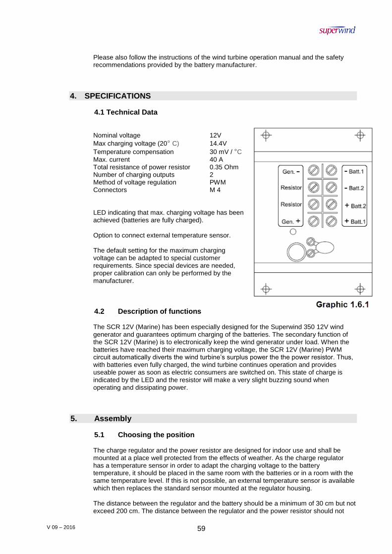
V 09 – 2016 59
Please also follow the instructions of the wind turbine operation manual and the safety recommendations provided by the battery manufacturer.
4. SPECIFICATIONS
4.1 Technical Data
Nominal voltage 12V
Max charging voltage (20° C) 14.4V
Temperature compensation 30 mV / °C Max. current 40 A Total resistance of power resistor 0.35 Ohm Number of charging outputs 2 Method of voltage regulation PWM Connectors M 4 LED indicating that max. charging voltage has been achieved (batteries are fully charged). Option to connect external temperature sensor. The default setting for the maximum charging voltage can be adapted to special customer requirements. Since special devices are needed, proper calibration can only be performed by the manufacturer.
4.2 Description of functions The SCR 12V (Marine) has been especially designed for the Superwind 350 12V wind generator and guarantees optimum charging of the batteries. The secondary function of the SCR 12V (Marine) is to electronically keep the wind generator under load. When the batteries have reached their maximum charging voltage, the SCR 12V (Marine) PWM circuit automatically diverts the wind turbine’s surplus power the the power resistor. Thus, with batteries even fully charged, the wind turbine continues operation and provides useable power as soon as electric consumers are switched on. This state of charge is indicated by the LED and the resistor will make a very slight buzzing sound when operating and dissipating power.
5. Assembly
5.1 Choosing the position The charge regulator and the power resistor are designed for indoor use and shall be mounted at a place well protected from the effects of weather. As the charge regulator has a temperature sensor in order to adapt the charging voltage to the battery temperature, it should be placed in the same room with the batteries or in a room with the same temperature level. If this is not possible, an external temperature sensor is available which then replaces the standard sensor mounted at the regulator housing. The distance between the regulator and the battery should be a minimum of 30 cm but not exceed 200 cm. The distance between the regulator and the power resistor should not

V 09 – 2016 60
exceed 200 cm. The power resisor must be ventilated properly. Never mount the power resistor on a flammable surface and take care that no flammable items will be close to the resistor. Consider the resistor will dissipate all the wind turbine’s power into heat when the batteries are fully charged. As a note: if installing on a yacht, a good place for the power resistor is the engine compartment.
5.2 Connecting the charge regulator
Before connecting the charge regulator, prevent your wind turbine from unintended starting. Connect the two generator cables together (CAUTION: make sure to disconnect the battery before!) or tie one of the rotor blades loosely to the mast (if accessible).
Slide the regulator’s black cover sidewards and take it off.
Mount the regulator and the power resistor to a dry, plain, and non-flammable surface. Use appropriate mounting holes. For connecting the cables to the charge regulator, use the yellow solderless terminals. The solderless terminals provided are suitable for cable cross-sections from 2.5 mm2 to 6.0 mm2 (AWG 13 to AWG 10). Use a crimping tool suitable for insulated terminals and check that the terminal has been securely crimped to the bared part of the cable. Connect the regulator as shown in Diagram 1.8.1 below.
To prevent your system from damages, the cables must be connected in the order described below.
1. Connecting the power resistor
Connect the power resistor to the terminals labeled ‘Resistor’ on the charge regulator. The cross-section of the cables must be a minimum of 4 mm2 (AWG 12).
2. Connecting the wind generator
Connect the wind generator to the terminals labeled ‘Gen +‘ and ‘Gen –‘ on the charge regulator.
Never interchange the polarity of the cables. Interchanged polarity would destroy the charge regulator and void the warranty.
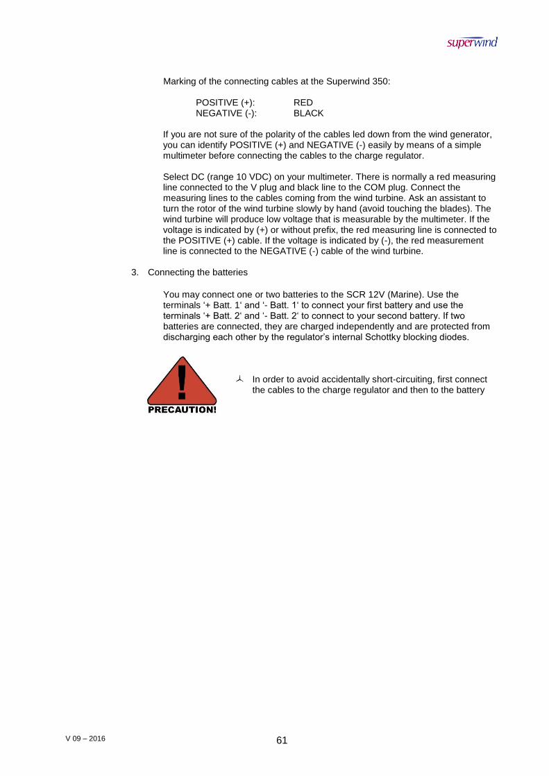
V 09 – 2016 61
Marking of the connecting cables at the Superwind 350: POSITIVE (+): RED NEGATIVE (-): BLACK
If you are not sure of the polarity of the cables led down from the wind generator, you can identify POSITIVE (+) and NEGATIVE (-) easily by means of a simple multimeter before connecting the cables to the charge regulator. Select DC (range 10 VDC) on your multimeter. There is normally a red measuring line connected to the V plug and black line to the COM plug. Connect the measuring lines to the cables coming from the wind turbine. Ask an assistant to turn the rotor of the wind turbine slowly by hand (avoid touching the blades). The wind turbine will produce low voltage that is measurable by the multimeter. If the voltage is indicated by (+) or without prefix, the red measuring line is connected to the POSITIVE (+) cable. If the voltage is indicated by (-), the red measurement line is connected to the NEGATIVE (-) cable of the wind turbine.
3. Connecting the batteries
You may connect one or two batteries to the SCR 12V (Marine). Use the terminals ‘+ Batt. 1‘ and ‘- Batt. 1‘ to connect your first battery and use the terminals ‘+ Batt. 2‘ and ‘- Batt. 2‘ to connect to your second battery. If two batteries are connected, they are charged independently and are protected from discharging each other by the regulator’s internal Schottky blocking diodes.
In order to avoid accidentally short-circuiting, first connect the cables to the charge regulator and then to the battery

V 09 – 2016 62
V 09 – 2016 63
Attachment C Superwind Charge Regulator 24V (Marine)
Manual
09-2016
V 09 – 2016 64
INSTALLATION
PLEASE DO NOT PROCEED UNTIL YOU HAVE READ
ALL INSTRUCTIONS AND
SAFETY INFORMATION
© 2016 superwind GmbH. Superwind is a Registered Trade Mark of superwind GmbH, Germany
MANUAL VERSION 09-2016

V 09 – 2016 65
1. GENERAL INFORMATION
1.1 General Information
The Superwind Charge Regulator (SCR) 24V (Marine) is a charge regulator of the highest quality and will perfectly and reliably charge your batteries for many years. However, reliable operation not only will depend on product quality but also on accurate assembly and proper wiring. Please read this manual carefully before you start the installation. Please also keep in mind our safety instructions and warning notices. Our main concern is with your safety.
1.2 Labelling
This manual refers to the Superwind Charge Regulator (SCR) 24V (Marine). Manufacturer: superwind GmbH Am Rankewerk 2-4 D-50321 Brühl Germany Tel.: +49 / 2232 / 577357 Fax: +49 / 2232 / 577368 E-Mail: [email protected] Internet: www.superwind.com
You will find the label with the serial number and the nominal voltage on the side of the housing.
1.3 Intended use and range of application The SCR 24V (Marine) is designed to sense and limit the output voltage of a Superwind 350 24V wind generator and thus to prevent batteries from becoming overcharged. It is suitable for lead acid batteries, gel batteries, and AGM (Absorbed Glass Mat) batteries, and has two battery charging outputs isolated by Schottky blocking diodes. This allows the wind turbine to charge two batteries totally independent of each other. The SCR 24V (Marine) is not influenced by other power sources connected to the batteries like alternators, gensets, solar arrays, and battery chargers. For that reason, it can be used very well in complex systems and hybrid systems. The regulator is fully potted to protect the electronics against humidity and vibration. Fields of application can be sailing yachts, campers, summer cottages, mountain shelters, as well as industrial applications like navigational aids, traffic management systems, environmental monitoring stations, or transmitters.
2 WARRANTY
2.1 Warranty
superwind GmbH warrants this product to be in good working order during the warranty period. In the event that the product is found to be defective within the warranty period, repair service will be provided free of charge by superwind GmbH or an authorized service partner.
V 09 – 2016 66
Free repair service may only be obtained by providing the warranty card and original purchase invoice issued to the customer by the retailer. The warranty card must state the purchaser ́s name, the retailer ́s name and address, the serial number and the date of purchase of the product. superwind GmbH reserves the right to refuse warranty service if this information is not complete or has been removed or changed after the original purchase of the product from the retailer.
2.2 Warranty period
The warranty is valid for three years from the date of purchase by the purchaser, as evidenced by the above mentioned documents.
2.3 To obtain warranty service
Warranty service is available at superwind GmbH and Superwind authorized service partners. Any costs of secure transportation of the product to and from superwind GmbH / Superwind authorized service partners will be borne by the customer.
2.4 Limitations
superwind GmbH does not warrant the following:
Periodic check-ups, maintenance and repair or replacement of parts due to normal wear and tear.
Defects caused by modifications carried out without superwind ́s approval.
o Includes damage caused by improper use, handling or operation, in particular
defects caused by improper installation and installation on inadequate masts or support structures.
Installation on inadequate masts or support structures (to obtain warranty service the purchaser has to provide evidence that masts or support structures are as recommended in the Superwind 350 manual).
Accidents or disasters or any cause beyond the control of superwind GmbH, including but not limited to lightning, flooding, fire etc.
Costs for disassembly and reassembly of the product to enable shipment for warranty reasons.
2.5 Others
Superwind GmbH reserves the right to decide whether the product or parts thereof shall be repaired or replaced under warranty. Should neither repair nor replacement by superwind GmbH be possible, the purchaser solely will be entitled to a full or partial refund (prorated when returned to the manufacture after more than 1 year of use).
This warranty does not affect the purchaser ́s statutory rights under applicable national legislation in force, nor the purchaser ́s right against the retailer arising from the sales / purchase contract. In the absence of applicable national legislation, this warranty will be the purchaser ́s sole and exclusive remedy, and superwind GmbH shall not be liable for any incidental or consequential damages for breach of any expressed or implied warranty of this product.
THE GENERAL CONDITIONS FOR THE SUPPLY OF PRODUCTS AND SERVICES OF THE ELECTRICAL AND ELECTRONICS INDUSTRY APPLY WITH APPROPRIATE LIMITS AND STANDARDS.
2.6 Expenses and Responsibilities
All associated expenses (shiping to and from the repair facility, insurance, etc) are the full responsibility of the buyer or his shipping agent, unless the buyer is notified otherwise by the manufacturer.

V 09 – 2016 67
Upon receipt of your unit:
The crate should be opened and inspected immediately for damage. Note any damage to the outside of the package (dents, scratches, etc.) and
document it on the Bill of Lading before signing and keep a copy. Documenting damage with photos is also highly recommended.
Unpack the unit at once and perform a visual inspection to determine if it is dented, bent or scratched.
If for any reason the unit should need to be returned, the original crate is the best way to ship it back to the manufacturer.
2.7 Claims
Claims that occur during transportation must be filed by the consignee (the buyer) as shipping terms are FOB-EX-WORKS (our distribution point as contracted).
BUYER IS RESPONSIBLE FOR ALL SHIPPING EXPENSES INCLUDING CUSTOMS DUTIES AND VAT (IMPORT DUTIES).
2.8 Exclusion of liability The manufacturer shall not be liable for damages caused by use other than as intended or mentioned in this manual, or if the recommendations of the battery manufacturer were neglected. The manufacturer shall also not be liable if there has been service or repair carried out by any unauthorized person, unusual use, incorrect installation, or inappropriate system design. Opening the charge regulator voids the warranty.
3 SAFETY INSTRUCTIONS
Please carefully study this manual before starting assembly and installation. The information provided is to ensure your safety during mounting, operation, and in case of trouble. If you have any additional questions please contact your dealer, a Superwind service partner, or the manufacturer.
3.1 General safety recommendations
Always abide by the acknowledged rules of any technology and the rules for accident prevention when working on the electrical system!
Take care that work on the electrical system like installation, maintenance, and repair is carried out by qualified persons only. These persons must also have studied the instructions given in this manual.
Batteries store a large amount of energy. In any circumstance, avoid short-circuiting the battery. For your safety, connect a fuse to each of the battery cables. Charging lead-acid batteries produces inflammable hydrogen gas. Unsealed lead-acid batteries have vent holes, releasing hydrogen, which forms detonating gas when mixed with ambient air. A small spark (e.g. from an electrical switch) can detonate the explosive gas mixture. For prevention, always provide sufficient ventialtion. Avoid touching and short-circuiting wires or terminals. Be aware that the voltage on specific terminals or wires can be significantly higher than the nominal battery voltage. Only use isolated tools, stand on dry grounds, and keep your hands dry.
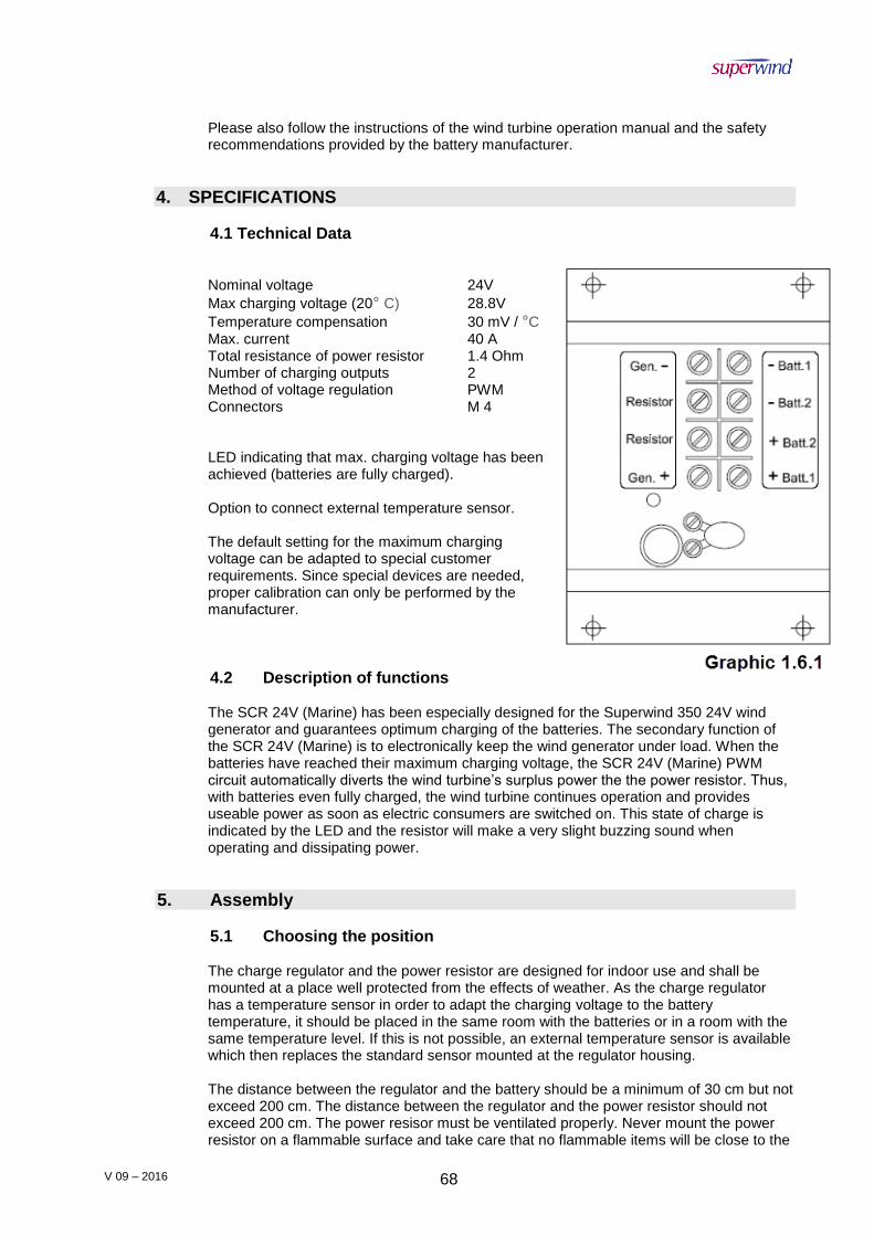
V 09 – 2016 68
Please also follow the instructions of the wind turbine operation manual and the safety recommendations provided by the battery manufacturer.
4. SPECIFICATIONS
4.1 Technical Data
Nominal voltage 24V
Max charging voltage (20° C) 28.8V
Temperature compensation 30 mV / °C Max. current 40 A Total resistance of power resistor 1.4 Ohm Number of charging outputs 2 Method of voltage regulation PWM Connectors M 4 LED indicating that max. charging voltage has been achieved (batteries are fully charged). Option to connect external temperature sensor. The default setting for the maximum charging voltage can be adapted to special customer requirements. Since special devices are needed, proper calibration can only be performed by the manufacturer.
4.2 Description of functions The SCR 24V (Marine) has been especially designed for the Superwind 350 24V wind generator and guarantees optimum charging of the batteries. The secondary function of the SCR 24V (Marine) is to electronically keep the wind generator under load. When the batteries have reached their maximum charging voltage, the SCR 24V (Marine) PWM circuit automatically diverts the wind turbine’s surplus power the the power resistor. Thus, with batteries even fully charged, the wind turbine continues operation and provides useable power as soon as electric consumers are switched on. This state of charge is indicated by the LED and the resistor will make a very slight buzzing sound when operating and dissipating power.
5. Assembly
5.1 Choosing the position The charge regulator and the power resistor are designed for indoor use and shall be mounted at a place well protected from the effects of weather. As the charge regulator has a temperature sensor in order to adapt the charging voltage to the battery temperature, it should be placed in the same room with the batteries or in a room with the same temperature level. If this is not possible, an external temperature sensor is available which then replaces the standard sensor mounted at the regulator housing. The distance between the regulator and the battery should be a minimum of 30 cm but not exceed 200 cm. The distance between the regulator and the power resistor should not exceed 200 cm. The power resisor must be ventilated properly. Never mount the power resistor on a flammable surface and take care that no flammable items will be close to the

V 09 – 2016 69
resistor. Consider the resistor will dissipate all the wind turbine’s power into heat when the batteries are fully charged. As a note: if installing on a yacht, a good place for the power resistor is the engine compartment.
5.2 Connecting the charge regulator
Before connecting the charge regulator, prevent your wind turbine from unintended starting. Connect the two generator cables together (CAUTION: make sure to disconnect the battery before!) or tie one of the rotor blades loosely to the mast (if accessible).
Slide the regulator’s black cover sidewards and take it off.
Mount the regulator and the power resistor to a dry, plain, and non-flammable surface. Use appropriate mounting holes. For connecting the cables to the charge regulator, use the yellow solderless terminals. The solderless terminals provided are suitable for cable cross-sections from 2.5 mm2 to 6.0 mm2 (AWG 13 to AWG 10). Use a crimping tool suitable for insulated terminals and check that the terminal has been securely crimped to the bare part of the cable. Connect the regulator as shown in Diagram 1.8.1 below.
To prevent your system from damages, the cables must be connected in the order described below.
1. Connecting the power resistor
Connect the power resistor to the terminals labeled ‘Resistor’ on the charge regulator. The cross-section of the cables must be a minimum of 2.5 mm2 (AWG 13).
2. Connecting the wind generator
Connect the wind generator to the terminals labeled ‘Gen +‘ and ‘Gen –‘ on the charge regulator.
Never interchange the polarity of the cables. Interchanged polarity would destroy the charge regulator and void the warranty.
V 09 – 2016 70
Marking of the connecting cables at the Superwind 350: POSITIVE (+): RED NEGATIVE (-): BLACK
If you are not sure of the polarity of the cables led down from the wind generator, you can identify POSITIVE (+) and NEGATIVE (-) easily by means of a simple multimeter before connecting the cables to the charge regulator. Select DC (range 10 VDC) on your multimeter. There is normally a red measuring line connected to the V plug and black line to the COM plug. Connect the measuring lines to the cables coming from the wind turbine. Ask an assistant to turn the rotor of the wind turbine slowly by hand (avoid touching the blades). The wind turbine will produce low voltage that is measurable by the multimeter. If the voltage is indicated by (+) or without prefix, the red measuring line is connected to the POSITIVE (+) cable. If the voltage is indicated by (-), the red measurement line is connected to the NEGATIVE (-) cable of the wind turbine.
3. Connecting the batteries
You may connect one or two batteries to the SCR 24V (Marine). Use the terminals ‘+ Batt. 1‘ and ‘- Batt. 1‘ to connect your first battery and use the terminals ‘+ Batt. 2‘ and ‘- Batt. 2‘ to connect to your second battery. If two batteries are connected, they are charged independently and are protected from discharging each other by the regulator’s internal Schottky blocking diodes.
In order to avoid accidentally short-circuiting, first connect the cables to the charge regulator and then to the battery

V 09 – 2016 71