Embed Size (px)
Citation preview

SuperWay A Solar Powered Automated Public
Transportation System
College of Business, College of Engineering, College of Applied Sciences and Arts
December 9, 2013
First Edition
12/9/2013

P a g e | 1
Table of Contents Executive Summary ....................................................................................................................................... 5
2013-2014 ATN Development....................................................................................................................... 6
Team Organization .................................................................................................................................... 6
Team Roster .......................................................................................................................................... 6
Four Stage Design Process ........................................................................................................................ 7
Quality Function Development ............................................................................................................. 7
Functional Decomposition .................................................................................................................... 8
Concept Generation .............................................................................................................................. 8
Concept Evaluation ............................................................................................................................... 9
Bogie Team ............................................................................................................................................... 9
Systems Explanation ............................................................................................................................. 9
System Model ..................................................................................................................................... 11
Cabin Team ............................................................................................................................................. 22
System Explanation ............................................................................................................................. 22
Cabin Design ........................................................................................................................................ 24
Controls Team ......................................................................................................................................... 26
System Model ..................................................................................................................................... 27
Next Steps ........................................................................................................................................... 55
Solar Team .............................................................................................................................................. 56
System Explanation ............................................................................................................................ 56
Power Collection ................................................................................................................................. 56
Power Transfer .................................................................................................................................... 57
Frame .................................................................................................................................................. 57
Guideway Mount ................................................................................................................................ 57
Tracking .............................................................................................................................................. 57
System model ...................................................................................................................................... 58
Next Steps ........................................................................................................................................... 64
Guideway Team ...................................................................................................................................... 64
System Model ..................................................................................................................................... 64
Next Steps ........................................................................................................................................... 66
Human Centered Design Team ............................................................................................................... 67

P a g e | 2
What is Human Centered Desgin? ...................................................................................................... 67
Next Steps ........................................................................................................................................... 74
Station Team ........................................................................................................................................... 74
System Model ..................................................................................................................................... 74
Next Steps ........................................................................................................................................... 74
Tentative Future Schedule ...................................................................................................................... 75
References .................................................................................................................................................. 77
Appendix A: Bogie Design Requirements & Specifications ......................................................................... 79
Appendix B: Bogie House of Quality ........................................................................................................... 82
Appendix C: Powertrain Calculations .......................................................................................................... 84
Appendix D: Previous Concepts .................................................................................................................. 85
Appendix E: Track Switch Navigation .......................................................................................................... 95
Appendix F: Governing Equations ............................................................................................................... 98
Appendix G: Defunct Components and Analysis ........................................................................................ 99
Appendix H: Cabin Design Requirements & Specifications ...................................................................... 120
Appendix I: Cabin House of Quality .......................................................................................................... 123
Appendix J: Computer Engineering Project Requirements....................................................................... 124
Appendix K: Controls System Design Requirements and Specifications .................................................. 130
Appendix L: Guideway Design Requirements and Specifications ............................................................. 137
Appendix M: Guideway House of Quality ................................................................................................. 139
Appendix N: HCD Survey 1 Data and Results ............................................................................................ 140
Appendix O: HCD Survey 2 Data and Results ............................................................................................ 153
Appendix P: Solar Design Requirements and Specifications .................................................................... 163
Appendix Q: Solar House of Quality.......................................................................................................... 169
Appendix R: Station Design Requirements and Specifications ................................................................. 170
Appendix S: Station House of Quality ....................................................................................................... 172
Figure 1: Bogie Chassis ................................................................................................................................ 11
Figure 2: Bogie Chassis on Guideway .......................................................................................................... 12
Figure 3: Bogie LIM Drivetrain Cross Section .............................................................................................. 12
Figure 4: Guideway Switch from Below ...................................................................................................... 13
Figure 5: Guideway Switch from the Side ................................................................................................... 13
Figure 6: Bogie Switching Mechanism ........................................................................................................ 14

P a g e | 3
Figure 7: Passive Sway System Sketch ........................................................................................................ 15
Figure 8: Power Contact Comb Sketch ........................................................................................................ 15
Figure 9: Braking System Sketch ................................................................................................................. 16
Figure 10: LIM - Image courtesy of http://www.baldor.com/support/Literature/Load.ashx/BR1202-
G?LitNumber=BR1202-G ............................................................................................................................. 16
Figure 11: Aluminum Secondary for Lim - image courtesy of
http://www.discountsteel.com/items/Aluminum_Plate1.cfm .................................................................. 17
Figure 12: Hydraulic Cylinder - image courtesy of
http://www.northerntool.com/shop/tools/product_200511868_200511868 ......................................... 17
Figure 13: Hydraulic Reservoir - Image courtesy of
http://www.northerntool.com/shop/tools/product_200466863_200466863 ......................................... 18
Figure 14: Hydraulic Pump - Image courtesy of
http://www.northerntool.com/shop/tools/product_21759_21759.......................................................... 18
Figure 15: Poly-Soft - Hamilton Poly-Soft® Polyurethane Wheel 6x2-1/2 with Tapered Bearing. .............. 19
Figure 16: Ultralast - Hamilton Ultralast® Polyurethane Wheel 5x2 with Tapered Bearing. ...................... 19
Figure 17: Latch - Example: Doorman/Hood Latch (Auto Zone). ................................................................ 20
Figure 18: Industrial Design Team 1 concept cabin .................................................................................... 23
Figure 19: Industrial Design Team 2 concept cabin .................................................................................... 23
Figure 20: Industrial Design Team 3 concept cabin. ................................................................................... 24
Figure 21: Frame A modeled with Solidworks ............................................................................................ 24
Figure 22: Frame B modeled with Solidworks ............................................................................................ 25
Figure 23: Frame C modeled with Solidworks ............................................................................................ 26
Figure 24. Client/Server Architecture ........................................................................................................ 28
Figure 25. Overall Diagram of Control System ........................................................................................... 29
Figure 26. Controls System Station Design ................................................................................................ 30
Figure 27. Station Pod Request Sequence Diagram ................................................................................... 30
Figure 28. Pod Request Sequence Diagram ............................................................................................... 31
Figure 29. Pod Hierarchy of Commands .................................................................................................... 32
Figure 30. Emergency Pod Sequence Diagram .......................................................................................... 33
Figure 31. Master Controller Use Case ...................................................................................................... 34
Figure 32. Heathrow Airport Pod Simulator .............................................................................................. 35
Figure 33. Control System Network Component Diagram ........................................................................ 36
Figure 34. State diagram start of transit .................................................................................................... 39
Figure 35. State Diagram of Pod on Main Track ........................................................................................ 40
Figure 36. Controls System Master Device Subsystem Schematic ............................................................ 43
Figure 37. Master Device Subsystem Status Update Flowchart ................................................................ 44
Figure 38. Slave Device Subsystem Status Update Flowchart ................................................................... 45
Figure 39. Speed Control Subsystem Schematic ........................................................................................ 47
Figure 40. Speed Control Subsystem Flowchart ........................................................................................ 48
Figure 41. Object Detection Subsystem Flowchart .................................................................................... 50
Figure 42. Object Detection Subsystem Schematic ................................................................................... 51
Figure 43. Position Tracking Control Subsystem Schematic ...................................................................... 53

P a g e | 4
Figure 44. Position Tracking Control Subsystem Flowchart ....................................................................... 53
Figure 45. Guideway Switching Control Subsystem Schematic ................................................................. 54
Figure 46. Static Mount Concept ................................................................................................................ 58
Figure 47. Single Axis Tracking on a Horizontal Axis. .................................................................................. 59
Figure 48. Single Axis Tracking System on a Vertical Axis ........................................................................... 59
Figure 49. Single Axis Tracking System on a Tilted Axis .............................................................................. 59
Figure 50. 3D cad design of initial brainstorm session designs. ................................................................. 61
Figure 51. 3D cad design cut out of single axis system from brainstorm sessions. .................................... 62
Figure 52. 3D cad design of single axis tracker concept derived from brainstorm sessions. ..................... 62
Figure 53. 3D cad design of horizontal single axis tracker derived from brainstorm session. ................... 63
Figure 54. 3D cad design of tilted tracker derived from brainstorm session. ............................................ 63
Figure 55: Double I-beam profile ................................................................................................................ 65
Figure 56: Sample track section including switch section .......................................................................... 66
Figure 57 ..................................................................................................................................................... 69
Figure 58 ..................................................................................................................................................... 69
Figure 59 ..................................................................................................................................................... 70
Figure 60 ..................................................................................................................................................... 71
Figure 61 ..................................................................................................................................................... 71
Figure 62 ..................................................................................................................................................... 72
Figure 63 ..................................................................................................................................................... 72
Figure 64 ..................................................................................................................................................... 73
Figure 65 ..................................................................................................................................................... 73
Table 1: Bogie Prototype Production Schedule and Budget ....................................................................... 22
Table 1: Frame A modeled with Solidworks ............................................................................................... 25
Table 2. Controls System Network Component Diagram .......................................................................... 36
Table 3. Alternative Concepts for Design Consideration. ........................................................................... 58
Table 4. Criteria for Basic Decision Matrix .................................................................................................. 60
Table 5. Basic Decision Matrix .................................................................................................................... 60
Table 6: Deflection of various cross-sectional shapes ................................................................................ 64
Table 3. Full and 1/12 Scale Object Detection Specification Substitutions ............................................. 135

P a g e | 5
Executive Summary The SuperWay is a solar-powered Automated Transit Network (ATN) system designed for urban and
suburban areas, such as the Silicon Valley. The system is designed to provide an alternative to both the
personal automobile and public transportation. The ATN system costs less to construct and to maintain
than existing mass transit approaches, reduces wait and travel times, and is environmentally friendly
during operation due to being 100% solar powered. SuperWay is designed to be sustainable where
existing transit solutions are not.
The design challenge was divided in to six engineering components of cabin, propulsion, structure and
guideway, solar energy, control systems, and station design and two non-engineering
concerns: industrial design and human centered design. Each component was analyzed separately in
order to determine the best design. The design process included four stages: researching the state-of-
the-art in each functional area, developing functional specifications and constraints, selecting the
optimal technology in each functional area; and lastly, designing a prototype system. The route and
urban planning were also considered, which included corridor selection, land use entitlements, and
environmental impact assessment.
The entire system will be designed based on studies and research conducted by the human centered
design team. The research and calculations determined that the passenger cabin should fit six adults
and have approximate interior dimensions of 10ft length x 6ft width x 8ft height. The bogie is capable of
achieving a cruising speed of 60 miles per hour will be self-switching at the junctions. The cabin is to be
suspended from the guideway with a ground clearance of at least 14 feet. The columns that support the
guideway are to be made of A574 grade 50 steel. The guideway will have a double bar I-beam cross
section. Stations are to include angled-berth tracks, with options for sub-lines for higher traffic areas.
Solar panels will be controlled by a single axis tracking system on a vertical axis.. Control, schedule, and
routing of the vehicles use a hybrid centralized system, which holds supervisory authority over semi-
autonomous subsystems.

P a g e | 6
2013-2014 ATN Development
Team Organization The founding Spartan Superway Team (previously known as the SMSSV Team) consisted of
approximately 20 students from the colleges of engineering and business, with support from mentors
and an additional group of Urban Planning students. Since then, the team has nearly tripled in size.
The core roster primarily consists for Mechanical and Computer Engineering students, as well as a
number of Business students. The most significant change since the previous year is the formation of a
dedicated Human-Centered Design team with goal of keeping the Superway rider in mind throughout
the design process. Their efforts are further bolstered by the major involvement of Industrial Design
students from the Advanced Industrial Design and the Interface and Interaction Design classes led by Jim
Shook and Tingbin Tang, respectively.
The Fall 2013 semester did not see any involvement from Urban Planning students, but a new group will
be joining the project in the Spring 2014 semester. In addition, a class of Civil Engineering students will
also be joining the project with the specific goal of improving the steel design within the guideway and
station structures.
In keeping with the theme of an interdisciplinary project, the Spartan Superway project also exists as the
San José State University Spartan Superway Club, and is open to students of all disciplines that wish to
see dramatic change in global transportation.
Team Roster
Project Advisor: Dr. Burford Furman
Mentors: Maria Blum-Sullivan, Bryan Burlingame, Sam Ellis, Lizie Michel, and Ron Swenson
Program Managers: Alexander Cowley and Jaston Rivera
Bogie Team: Max Goldberg (Lead), David Lhotak, and Paolo Mercado
Business Team: Laisz Lam
Cabin Team: Alex Cowley (Lead), and Ken Ho
Controls Team: Cory Ostermann (ME Lead), Eriberto Velazquez (CMPE Lead), Man Ho, Marjo Mallari,
Randall Morioka, Elizabeth Poche, Trent Smith, and Anthony Vo (Spartan Superway Club member)
Human-Centered Design Team: Maria Blum-Sullivan (Lead), Alex Cowley, Jaston Rivera, and Ken Ho
Solar Team: Francisco Martinez (Lead), Jaston Rivera, Tim Santiago, and Henry Tran
Station/Guideway Team: Cormac Wicklow (Lead), Daniel Conroy, and Carlos Guerrero
Pod and Station Industrial Design Team: The students of DSID 125: Advanced Industrial Design, led by
Jim Shook.

P a g e | 7
User-Interface/User-Interaction Design Team: The students of DSID 131: Interactive and Interface
Design, led by Tingbin Tang.
Four Stage Design Process The process that the SMSSV mechanical engineering teams applied for the development of the
subsystems involved four stages. The four stages were quality function development, functional
decomposition, concept generation, and concept evaluation.
Quality Function Development
Quality function development (QFD) is the first stage in the design development process. QFD’s main
function is to understand the customer requirements and use those requirements to develop the
engineering specifications that form the foundation of the concepts. QFD is itself an eight-step process.
In addition, a house of quality, a visual representation of the QFD steps, builds from the results of QFD.
The house of quality has distinct sections that represent the steps of the QFD process.
1. Who: In this stage, the engineer researches the problem to determine who the customers will
be. Customers are not limited to the end user, but can range from manufacturers to city
officials. Customers are any group of people that have a stake in the development of the
product.
2. What: This stage is where the engineer researches the customer groups. The engineer gathers
information to understand what the customers want the product to be capable of doing, or
what features it may have.
3. Who Vs. What: This stage evaluates all requirements that came from stage 2 for each customer.
That means that the requirements that came from one customer receive a value for the other
customers. The engineer surveys the customer groups in order to determine which
requirements the customer values more. A common method of doing this is by using a fixed
sum method.
4. Now: This stage is used for the engineer to identify and evaluate the competition. Other
competing products undergo scrutiny for customer satisfaction, mechanical robustness, etc.
5. How: The “how” stage is the stage that the engineering specifications are developed. Each
customer requirement is required to have at least one specification that strongly satisfies it.
Some specifications may be able to satisfy other requirements to a varying degree. Step six
accounts for these special specifications the accounted. In addition, each specification must be
associated with an engineering parameter, i.e., there needs to be a unit of measurement
associated with the specification that compares one concept to another. If a specification is not
developed for a requirement, the engineer must return to step two and better understand the
requirement, possibly even turning it into two or more requirements.
6. How vs. What: The engineer will assess which requirements are satisfied by which specification
and to what degree. Generally, the specification either strongly, moderately, weakly, or will not
satisfy the requirement.
7. How vs. How: This stage is when the engineer analyzes the specifications to identify how each
specification relates to the other specifications. This is done to know if one specification that
doesn’t score highly in the previous step is still worth implementing or if two highly rated

P a g e | 8
specifications will be difficult to implement simultaneously. The specifications relate either
strongly positive, positive, no relation, negative, or strongly negative.
8. How Much: The engineer multiplies the score that each specification received by each oif the
customers’ requirements weights. This generates a value for each specification for each
customer. Specifications that rank highly will be specifications that will receive strong
consideration in design, while specifications that rank low will receive less attention unless they
relate strongly with another highly rated specification as determine in the previous step.
Functional Decomposition
Functional decomposition develops the function of the design, the sub functions, and the flow of
energy, information, and material of the system.
1. Define the function of the product. This single overreaching function describes the use of the
product.
2. Define the sub functions of the product. The engineer dissects the products functionality and
tries to link the specifications to the sub functions to show how the specifications satisfy the
functionality of the system. It is common that not all specifications satisfy functions and not all
functions will have specifications that satisfy them.
3. Refine and order the sub functions. The engineer looks deeper into the product and tries to
identify any sub functions that can be broken down into smaller functions. The engineer also
orders the sub functions in the way that information, energy, or material will flow through the
product.
4. Identify the flow of Material, Information, and Energy
a. The flow of material identifies by the way that the product processes any tangible
material. At any junction the material will converge, diverge, or be conserved.
b. The flow of information is defined by the way that signals are processed in the system
c. The flow of energy is the way that energy propagates through the product. Energy can
take many forms such as mechanical, chemical, pneumatic, electrical, etc.
Concept Generation
This stage is where the engineer or team of engineers generates different concepts that satisfy the
specifications developed in QFD. Several methods that used for this stage are as follows
1. Brainstorming is the most general concept generation technique. Engineers attempt to come up
with as many ideas as possible without critique.
2. The 6-3-5 method is where six engineers develop 3 ideas for 5 minutes, then pass their ideas
around the in a circle to the other engineers for 5 minute intervals between each pass. The
engineers sit in silence and only add to the original concept without critique. When the session
ends, the engineers cluster their ideas together.
3. Use of analogies is where engineers look at the way other things are done such as in nature to
generate solutions.
4. Engineers can use trade journals and books to generate concepts.
5. Engineers can consult experts and other professionals to get their input and ideas.
6. The TRIZ method bases off work that categorizes patents. The categorization suggests solutions
that can solve problems with specification engineering parameters.

P a g e | 9
Concept Evaluation
In this stage, engineers reduce all concepts to one final design concept. There are several methods of
evaluating the concepts. Use of multiple methods is desirable to eliminate unsatisfactory concepts.
1. Feasibility assessment is where the engineer uses intuition to eliminate concepts that simply are
not feasible
2. Access to technology is a limiting factor that causes elimination of some concepts that require
expensive or obscure technology.
3. The go/no-go method is a method to eliminate concepts that simply do not satisfy enough of
the requirements, specifications, or require information that is not readily available.
4. The Pugh’s method is a simply decision matrix that compares the remaining concepts using the
specifications as criteria. This method can be used to determine the final design
5. If some concepts rank closely in the Pugh’s Method a more robust method is used. The robust
method uses the concept of a belief map, in which knowledge and confidence in the capability
of satisfying the specifications is used to rank the concepts. This method will determine the final
concept for design.
Bogie Team On the Superway PRT vehicle, the bogie is the component which navigates the guideway and supports
the cabin and its passengers. It is responsible for propulsion, braking, structural support, sway control,
track switching, and interfacing with the power conduits located on the track. The bogie is located above
the cabin.
Systems Explanation
The systems of the Superway bogie have been selected to fulfill Design Requirements and Specifications.
For a full breakdown of the Design Requirements and Specifications, please see Appendix A.
System Interfaces
The bogie team is responsible for all structure and components between the guideway and the roof of
the cabin. The following interfaces exist between the bogie subsystems and the other components of
the Superway design:
Wheels/rollers in contact with the guideway
Mounting points on the roof of the cabin
Contact points to transmit power to the bogie from the 3rd rail
Communication between control system and bogie controller (method TBD)
Electromagnetic interface between aluminum strip and LIM (if LIM propulsion is used)
Subsystems
The functions and components of the Superway bogie are broken down into seven subsystems as
described below.

P a g e | 10
Chassis
The main function of the bogie chassis is to provide structural support for the interface between the
cabin and the guideway. The chassis consists of internal framework that not only holds the cabin, but
supports all the other components and subsystems on the bogie. The chassis also provides tow points
located on the front and back of the bogie to allow the option of emergency towing in case of an
emergency or bogie breakdown.
Rolling System
The rolling system consists of support and guiding wheels that can handle all of the weight and stresses
that the bogie and cabin may run into during operation use. The support wheels are the direct point of
contact between the bogie chassis and the guide way. The support and guiding wheels must suspend
and stabilize the bogie within the track to provide smooth and safe propulsion on both straights and
corners.
Powertrain
The powertrain located within the bogie is responsible for generating and providing power that results
in an output of motion. It is solely responsible for moving the bogie and cabin down the guide way at
speeds up to 60 miles per hour, along with acceleration and deceleration at up to 2 meters per second
squared.
Steering/Switch
The steering and switch system is responsible for allowing both the bogie and cabin to turn either to the
left or right at a switching junction based on the desired destination. The system consists of on-board
switching to provide fast and safe switching at each junction for each bogie that is in operation. The
primary requirement for the switch is that it must decisively select a direction, as indecisive selection
can cause a derailment.
Sway System
Due to the high speeds and weight that the bogie and cabin must deal with, the sway system is a
necessary component to make the ride comfortable for the passengers. The sway hinge allows the cabin
to bank during cornering. The main function of sway system is to provide a comfortable and smooth ride
within the bogie in all conditions and corners. Sway control stabilizes the cabin, which as a result
minimizes any uncomfortable angles and movements an individual may experience while riding in the
cabin. It prevents reciprocating swinging motions from wind and cornering forces.
Power Interface
The entire system ranging from the components on the bogie and the controls in the cabin depend on
electrical power. The power interface provides alternating-current electric power for all the components
that run on electricity.
Braking System
The braking system is responsible for assisting the regenerative braking effects of the propulsion system
when needed, to hold the bogie steady while passengers get on and off, and to provide an emergency

P a g e | 11
braking function in the case of a systems failure. The emergency brake system is capable of producing a
deceleration of 0.6g.
System Model
Introduction to prime design
The bogie team’s prime design is the result of an iterative process between the bogie and guideway
teams. It took several iterations to arrive at a final design for the cross section of the guideway. To see
previous iterations of the bogie design, see Appendix D.
The prime design bogie will run along an I-beam shaped guideway, with wheels contacting the outside
edge of the top of the lower flange for support, wheels contacting the sides of the center of the I-beam
to keep the bogie centered, and wheels contacting the bottom of the upper flange for cornering
stability. Propulsion is achieved via LIM motors which interface with aluminum panels running along the
bottom of the I-beam.
Subsystems
Chassis
The structure of the bogie chassis will be constructed as a welded tubular steel frame, with solid steel or
aluminum components where needed. It will consist of the undercarriage (A), support beams (B) and the
roller runners (C).
Figure 1: Bogie Chassis
The rolling system of the chassis will consist of 24 rollers attached to the roller runners. Eight rollers, two
at each support beam, will hold the weight of the bogie and cabin. Each roller will be strong enough to
support ¼ of the weight of the cabin-bogie system. The eight rollers on the outer edge of the bogie are

P a g e | 12
used only during a track switch (more information on this function is described in the below section on
the steering/switch system).
Figure 2: Bogie Chassis on Guideway
Powertrain
Propulsion of the bogie is achieved with linear induction motors (LIM’s). A LIM consists of a stator coil
assembly which exerts a force on a “rotor” assembly when an alternating current is passed through the
stator coil (Woodford). The “rotor” assembly is a plate of aluminum (ABB Motion Control). LIM’s are
useful in this design because of their nearly infinite life cycle, low friction, smooth operation, and
compact size. Conventional traction motors can be used, but they greatly increase the size of the bogie
and require a system to apply pressure to the drive wheels in order to gain traction against the bottom
of the guideway.
The stator assemblies are mounted to the undercarriage, and the aluminum plate is attached to the
bottom of the Guideway.
Figure 3: Bogie LIM Drivetrain Cross Section

P a g e | 13
Steering/Switch
For safety reasons, guideway switching on an ATN cannot be handled by a mechanism installed at the
guideway switch. The Superway bogie has been designed to select a direction and navigate a guideway
switch on its own
Figure 4: Guideway Switch from Below
At the guideway switch (shown above), there are additional support beams to the left and right of the
guideway which engage the rollers on the outer edge of the bogie roller runners.
Figure 5: Guideway Switch from the Side
This design ensures that the switch is navigated without a loss of support force. For an illustration of this
system in work, see the diagrams in the Appendix E.

P a g e | 14
Selection of a guideway direction is achieved with a mechanism (with 4 rollers, shown in red) in the
undercarriage.
Figure 6: Bogie Switching Mechanism
This mechanism engages a flange (A) which runs along the bottom of the additional support beams. The
lateral force required to steer the bogie in the correct direction is applied by the engaged roller (B) at
this flange. The horizontal rollers on the outer edge of the runners also engage the additional support
beam to restrict the motion of the bogie. The design of the switching mechanism prevents the bogie
from ever engaging both sides of the guideway.
In order to maintain the position of the mechanism even during a power failure, there are latches (C)
which hold the mechanism in place. To switch positions, the actuators must activate and the latches
must release. The actuation method has not yet been determined.
Sway System
The cabin will be allowed to bank or sway when cornering via a hinge type mechanism attached to the
undercarriage. There are two proposed systems to control this swaying motion.
Passive Non-Newtonian
The passive design consists of assemblies similar to coil-over shock absorbers which attach to the roof of
the cabin on one end and to the top of the undercarriage on the other. These hydraulic cylinders are
filled with a non-newtonian fluid and are connected with a hydraulic line. When the cabin sways, one
cylinder compresses, forcing fluid through the hydraulic line (providing damping force) and into the
other cylinder. If this swaying motion occurs abruptly, the fluid will become much more viscous, limiting
the sway due to sudden wind loading.

P a g e | 15
Figure 7: Passive Sway System Sketch
Active Hydraulic
In the case that the passive system fails to provide a comfortable ride for the passengers, an active
system will be employed. In place of the coil-over shock absorbers will be simple hydraulic cylinders. An
electrically powered computer controlled hydraulic system will be able to apply hydraulic force
individually to each cylinder, enabling it to control the angle of the cabin. An algorithm will determine
the optimum angle for passenger comfort.
Power Interface
Depending on the power requirements of the linear motor driver, either one-phase or three-phase AC
power is delivered to the bogie through a hot rail or a system of hot rails on the bottom of the
guideway. A spring loaded contact presses into this rail from the undercarriage. If multiple rails are used,
a comb-type contact, as depicted below, makes contact.
Figure 8: Power Contact Comb Sketch
Braking
A braking system provides braking force for stopping in emergency situations as well as to supplement
the regenerative braking of the LIM. It consists of ceramic brake pads which are forced against the sides
of the center of the I-beam with hydraulic cylinders similar to those in brake calipers.

P a g e | 16
Figure 9: Braking System Sketch
Actuation of a hydraulic master cylinder can be achieved with any linear actuator. A supplementary
mechanical actuation method will be available via a cable which can be pulled by occupants of the cabin
to execute an emergency stop in the case of a total systems failure.
Components
This section contains off-the-shelf components which are needed to build the Superway bogie. It does
not include raw materials. The listed components will satisfy our requirements, but are open to
replacements if better alternatives are found.
Linear Induction Motors
Figure 10: LIM - Image courtesy of http://www.baldor.com/support/Literature/Load.ashx/BR1202-G?LitNumber=BR1202-G
Linear induction motors (LIMs) are the motors chosen to accomplish the difficult high speed and torque
requirements. The main advantage of using linear induction motors is that they “provide direct-coupled
motion and eliminate mechanical transmission devices (Linear Motors and Stages). In laymen’s terms,
they don’t need to touch the guideway to move along it. This is very critical for the bogie and design of
the entire system because a major goal is to make all of the components as reliable and compact. Since
a transmission is not used with LIMs, weight is cut significantly and the overall design of the bogie is
much simpler. A linear induction motor works by the principles of induction. Unlike the traditional
electric motor that has a rotor that spins inside of the stator, A LIM has a stator that is fully unrolled and
flat while the rotor moves by it in a linear movement, which is where the name “Linear induction motor”
comes from (How Linear Induction Motors Work).
Based on calculations and research that can be viewed in Appendix C, it was determined that a total of
54 horsepower is necessary to provide the necessary propulsion for steep guide way elevation changes
up to 10%. It was determined that the best way to meet the horsepower requirement was with 2 high
power linear induction motors. The LMAC1615C23D15 motor from BALDOR provides a total of 28
horsepower at 15% duty cycle, which gives a total of 56 horsepower for a combination of 2 motors. Each

P a g e | 17
LMAC1615C23D15 motor supplies a 1,156N force at 15% duty cycle from a 460-volt alternating current
3-phase power supply. Each motor comes out to a mere weight of 140 pounds (Linear Motors and
Stages).
Aluminum Secondary for LIM
Figure 11: Aluminum Secondary for Lim - image courtesy of http://www.discountsteel.com/items/Aluminum_Plate1.cfm
Aluminum sheets of metal are required to be mounted on the underside of the guide way to provide.
Aluminum is an excellent electrical conductor that is significantly cheaper than copper and provides
great corrosion resistance. 5052-H32 Aluminum sheets were chosen as the metal of choice because of
the characteristics that it provides. 5052-H32 Aluminum provides “superior resistance, good weldability,
with excellent formability” (Aluminum Plate). A sheet metal thickness of .125 inches is required by the
chosen linear induction motor, and upon further research we found that 2 feet by 2 feet sheets would
be adequate. Each .125 inch thick 5052-H32 Aluminum sheet metal piece that has a length and width of
2 inches costs $43.20 (Aluminum Plate).
Hydraulics System
Hydraulic systems are considered in the bogie design to play a role in the steering and anti-sway system.
Hydraulic Cylinder
Figure 12: Hydraulic Cylinder - image courtesy of http://www.northerntool.com/shop/tools/product_200511868_200511868
Hydraulic cylinders would be interfaced between the bogie and cabin to act as an anti-sway system.
Hydraulic cylinders are also being considered in the steering system to provide the necessary force to
change the position of the steering arm and allow the bogie to follow a specific direction at a guide way
junction. The hydraulic cylinder provides a unidirectional force that is highly accurate and reliable. A
LION TH Tie-Rod Cylinder that operates at high working pressures up to 3000 PSI has been chosen
because of its mechanical abilities and large output force. It is an industrial strength hydraulic cylinder

P a g e | 18
that is made out of heavy-duty iron for reliability and longevity to provide a maximum stroke length of 8
inches at a total price of $129.99 (Northern Tool+Equipment).
Hydraulic Reservoir
Figure 13: Hydraulic Reservoir - Image courtesy of http://www.northerntool.com/shop/tools/product_200466863_200466863
A hydraulic reservoir acts as a storage area for either hydraulic fluid or Non-Newtonian fluid. The
Nortrac steel hydraulic oil tank was chosen for the hydraulic reservoir because of its heavy-duty 12-
gauge steel construction and 4.8 gallon fluid capacity. It has mounting brackets for easy installation and
can be purchased for $89.99 (Northern Tool+Equipment).
Hydraulic Pump
Figure 14: Hydraulic Pump - Image courtesy of http://www.northerntool.com/shop/tools/product_21759_21759
A hydraulic pump is necessary to force fluid into the hydraulic cylinder in active hydraulic systems. The
force of fluid within a hydraulic cylinder allows the hydraulic shaft to extend and withdraw. The
hydraulic pump chosen is a Prince Hydraulic PTO tractor pump that is capable of delivering 40.1 gallons
of oil per minute (Northern Tool+Equipment). It is an industrial size pump that has high reliability and is
expected to be maintenance free.
Non-Newtonian Fluid
Non-Newtonian fluid is considered as a possible fluid for the passive anti-sway system because of its
unique viscosity properties. Non-Newtonian fluid would be used inside of the hydraulic cylinders that
are mounted between the bogie and cabin. If the cabin were to make a sudden movement or jolt, the
Non-Newtonian fluid would become highly viscous, resisting that motion. A non-corrosive Non-
Newtonian fluid would be used to provide maintenance free operation.

P a g e | 19
Wheels
Support Rollers
Figure 15: Poly-Soft - Hamilton Poly-Soft® Polyurethane Wheel 6x2-1/2 with Tapered Bearing.
The Poly-Soft® material is designed to be both durable and compliant, which should minimize the
vibrations transmitted to the cabin. Each wheel can support up to 1300 lbs. (Hamilton)
Guiding rollers
Figure 16: Ultralast - Hamilton Ultralast® Polyurethane Wheel 5x2 with Tapered Bearing.
The Ultralast® material is more rigid that the Poly-Soft® material, which should increase longevity of the
part. Because the guiding rollers don’t have to support the weight of the vehicle, the vibrations are less
severe. This particular wheel can support up to 1250 lbs. (Hamilton)
Latches
In order to hold the steering system in place, a mechanism such as an automobile hood latch can be
utilized. If such a mechanism isn’t strong enough to handle the forces imparted on it during a guideway
switch, a custom latch will be designed.

P a g e | 20
Figure 17: Latch - Example: Doorman/Hood Latch (Auto Zone).
Next Steps
These are the next steps that our team will take as we move forward with this project.
Continued Development
It is imperative that each and every system aboard the bogie have a fully developed design before
engineering analysis can be conducted on them.
Develop Undetermined Subsystem Models
Certain aspects of the prime design are currently undetermined. For these aspects and their relevant
subsystems, the next step is to develop finalized models. Affected subsystems include steering
actuation, braking, and sway control.
Continue Propulsion Research
LIM systems are far less common than rotary motor systems, and were only recently adopted for our
design. Further research into the control, operation, and selection of LIM systems is required.
Modeling and Analysis
The next natural step in the design process is to use our engineering knowledge to model and analyze
the bogie and its components to ensure its safe operation.
3D Modeling
A complete 3D model of the final bogie design is the target over the next few months. This will include
the additions of the drive system, switch actuators, emergency braking system, structural connection to
the cabin along with the sway system, and a potential traction system. Also, the rolling system and
switch arm designs will be finalized and refined to end specification.
Chassis Structural Analysis
Static Truss Analysis Static analysis of the structural members, axles, and wheels will be performed. Stresses will include
normal, tensile, torsion, and shear due to hanging weight. Governing equations for the proposed hollow
beams have been identified (see Appendix F), and adjusted accordingly to final design. Static analysis
will also be performed for instants in time when cornering forces are applied.

P a g e | 21
Static Force analysis at Motor Mounts
Motors will introduce forces and moments against the chassis members and the hardware they are
mounted with. Accounting for this force is necessary to prove sustainability of the motor
mounting/housing design.
Finite Element Analysis
Finite Element Analysis (FEA) will be utilized to provide detailed stress analysis and identify potential
weak points of the design in progress, helping with development as well as present a proven final
design. FEA will also be capable of modeling stress distribution in dynamic situations including
accelerating, braking, emergency braking, and wind.
Life Cycle Analysis
A life cycle analysis will be conducted on the chassis, wheels, and drive components as they are
subjected to continuous stress and force. It is an important component in measuring the longevity of the
bogie as a system and in the interest of economics. Such analysis will help reduce the required safety
factor used and ensure the reliability of the bogie.
Steering System Analysis
Static Bending Analysis and mount analysis Stress analysis will be applied to dynamic and static situations in corners. This is necessary to design an
appropriately sized steering arm and to ensure the system maintains rigidity when subjected to
cornering forces.
Dynamic Analysis
The actuation of the steering system will need to be modeled dynamically to ensure that the actuator is
capable of switching the steering mechanism rapidly and reliably.
Life Cycle Analysis
Along with the chassis, a life cycle analysis will be conducted on the steering system. Reliability of the
system will be an important matter as malfunction or failure will result in improper rail selection, forcing
the bogie to stop in the guideway to await repairs.
Construction Schedule
Pending funding, the below construction schedule outlines the phases with which we intend to proceed
to build a full scale working model of the Superway bogie for demonstration and testing purposes. It
also estimates the cost of each phase. Cost estimates should be considered very rough.

P a g e | 22
Table 1: Bogie Prototype Production Schedule and Budget
Cabin Team Public transportation as it currently stands is very inefficient and unreliable. The cabins are highly
congested, causing passengers to experience an uncomfortable ride to their destination. SuperWay
aims to improve the ridership experience by developing a cabin design that not only alleviates stress but
also provides as a pleasant and alternative mode of transportation.
System Explanation
The concept of the cabin is to carry passengers quickly and safely to their desired destination that is also
aesthetically pleasing, giving them a more personalized experience. The cabin team aims to give the
passenger a semi-controlled interaction similar to that in which they would have in their own
automobile. In order to accomplish this the engineering team along with the industrial design team
took a human centered design approach. This allowed for optimal design so that the end customer is
the focal point. The cabin must also be ADA compliant and incorporate standards for public
transportation vehicles.
This school year the cabin team, while incorporating some of the ideas from last year, took a slightly
different approach to come up with the design of the cabin. The cabin team focused on the design
process (See Appendix APPREF Four Stage Design Process) in order to come up with a sound design
that meets all requirements and specifications (See Appendix APPREF Cabin Design Requirements and
Specifications). The engineering aspect of the cabin team also had the assistance of the industrial design

P a g e | 23
cabin team to work through many concepts of what the interior and exterior of the cabin should look
and feel like, shown in Figure 1, 2, 3.
Figure 18: Industrial Design Team 1 concept cabin
Figure 19: Industrial Design Team 2 concept cabin
P a g e | 24
Figure 20: Industrial Design Team 3 concept cabin.
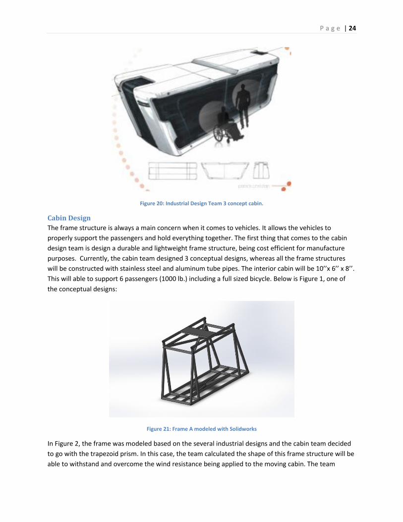
Cabin Design
The frame structure is always a main concern when it comes to vehicles. It allows the vehicles to
properly support the passengers and hold everything together. The first thing that comes to the cabin
design team is design a durable and lightweight frame structure, being cost efficient for manufacture
purposes. Currently, the cabin team designed 3 conceptual designs, whereas all the frame structures
will be constructed with stainless steel and aluminum tube pipes. The interior cabin will be 10’’x 6’’ x 8’’.
This will able to support 6 passengers (1000 lb.) including a full sized bicycle. Below is Figure 1, one of
the conceptual designs:
Figure 21: Frame A modeled with Solidworks
In Figure 2, the frame was modeled based on the several industrial designs and the cabin team decided
to go with the trapezoid prism. In this case, the team calculated the shape of this frame structure will be
able to withstand and overcome the wind resistance being applied to the moving cabin. The team

P a g e | 25
decided to use Alloy Steel for the main section of the cabin because of its benefits in regards to ductility,
high temperature strength, machinability which allows for easier manufacturing, and a high elastic ratio
and endurance strength to withstand impact. Aluminum 1060 was used for the sub-frame that acts as
the aerodynamic portion of the cabin because it is lightweight and will keep the overall weight of the
cabin at a minimum. Since this section does not have to bear a load it can be used to as a crumpling
zone for safety precaution in case of impact.
Table 2: Frame A modeled with Solidworks
Tube Materials Aluminum 1060 and Alloy Steel
Materials Tubing Size 1’’ OD x 0.095’’ Thickness
Frame Weight 266.88 lbs
Figure 22: Frame B modeled with Solidworks

P a g e | 26
Figure 23: Frame C modeled with Solidworks
Based on all the conceptual designs, the team makes sure the frame will be able to minimize the drag
force by making it as aerodynamic as possible without compromising visual appeal. Having an
aerodynamic cabin will put less load on the system and allow it to consume as lease amount of energy
as possible. Also, one of the main reasons the team decided on a trapezoid prism shape frame is
because the team would like the cabin to be able to travel bi-directional. This concept was implemented
based on (BART) current and previous automated transit system. For the development of the exterior
and interior, the cabin team will have further analyze on the system.
Next Steps
Moving forward the cabin team will perform calculations to determine the stress at all points of
connections within the various frame designs and their aerodynamic efficiency. This will allow us to
justify the cabin design and determine if any iterations need to be made. Sizing the HVAC system along
with lighting infrastructure needs to be determined. Wind affects on swaying of the cabin need to be
accounted for. Safety features and procedures need to be established. Upon completion of analysis the
cabin team will then begin building a full-scale model with materials to be used in a fully developed
system.
Controls Team The Spartan Superway Controls System sub-team develops and implements the software-related
components necessary to automate the transit network. At the highest level, this means that any
scheduled trip on the Spartan Superway system will run entirely without manual intervention, from the
moment a Superway rider purchases their ticket, to when they step off the pod at their final destination.
The underlying responsibilities within the Controls System to achieve such a goal range from
manipulating the pod motors to go forward, to providing a city-wide communications network capable
of monitoring and scheduling pod travel routes.

P a g e | 27
The Controls team responsibilities primarily consist of three main areas: the network architecture, pod
operations, and a 1/12 scale physical system model. The network architecture comprises all the front
end and back end elements that process the various client/server functions, such as receiving ride
requests, scheduling pod routes, and relaying information between the main server, stations, and pods.
Pod operations encompasses the software and hardware required to provide each individual pod with
sufficient local intelligence to allow autonomous operation, meaning that after receiving a single
message from the server, a pod will complete a trip without additional commands from the server. The
1/12 scale system model provides the testing platform for the network architecture and pod operations,
and helps ensure that the two components merge seamlessly.
During the 2012-2013 academic year, the founding team of Spartan Superway created the first iteration
of the Controls System elements and laid the groundwork for further development in the current
iteration. A joint effort between the Cabin, Bogie, Guideway, and Controls teams culminated in the
fabrication of the 1/12 scale model track and an accompanying pod design. Unfortunately, the semester
time constraints prevented the Controls team from achieving a network architecture and pod
operations system capable of intercommunication. Despite this hurdle, the previous Controls team
successfully produced a solid foundation for this year’s Controls team.
This year’s Controls team aims to improve upon the previous year’s design by introducing greater
flexibility and scalability into the system, ultimately creating a more robust system that the team can
quickly expand as external interest and funding increase. The previous year’s network architecture
system addressed a select set of test cases, and as a result, limited the possibility of introducing new
scenarios onto the test track. On the hardware side, the complexity of the previous year’s pod controls
setup made fabricating multiple test pods prohibitive due to resource and tool access. This year’s team
will focus on streamlining the hardware structure to arrive at a design that more closely meets the “plug
and play” testing needed for rapid software iteration.
System Model
The Spartan Superway Controls System model consists of two main components: the network and the
pods. The network system model is comprised of the overall network architecture design, the interface
and components, and the structure and logic design for the system. The system model for the pods
comprises the individual subsystems controlled by separate microcontrollers. Each of these subsystems
interfaces with a master controller, which serves as the interface between the pods and the network
and routes all the communications between each pod and the network. The pod system model
combines the following subsystems: the master device, speed control, object detection, position
tracking, and guideway switching control.
Network
Architecture Design
Project Superway’s control system employs known architectures that are used in many systems, such as
peer-to-peer and distributed. We will utilize these architectures in our design and modify them to fit
with our system. Overall, our system acts like a client/server architecture. The server is represented by

P a g e | 28
the master controller and the clients include: stations, remote stations, scheduler, and depots. The
clients will receive instructions from the master controller and will communicate necessary information
to the master controller. Shown in Figure 24, the master controller is the central server that has access
to all other controllers and has the authority to override any commands inside it and other controllers.
Figure 25shows the control system architecture that explains each component’s role.
Figure 24. Client/Server Architecture

P a g e | 29
Figure 25. Overall Diagram of Control System
The master controller is the central server that services requests from the scheduler, station, depots,
and remote stations. The master controller makes commands and decisions during emergencies.
Manual override can be accommodated through the master controller. The master controller will
monitor local conditions, individual pod status, and detect system malfunctions and emergencies. If the
master controller receives an emergency call, it will instruct the scheduler, station, pod, and remote

P a g e | 30
station controllers to follow their designated protocols. The station's responsibility is to service pods
that need to load or unload customers. When the customer’s reservation time is near, the station will
broadcast to the closest available pod. The available pods will respond with their location and the
station will decide which pod it will use. When a pod comes near the station to be load or unload, the
station will direct it to a parking spot and be serviced appropriately. Figure 26 is a diagram of the
station’s structure. Pods will be serviced at a first-come-first-serve (FIFO) basis. If there is an emergency
in a pod with passengers, the station will reschedule the pod so it will unload at the nearest station.
Figure 27 shows how a station requests an available pod.
Figure 26. Controls System Station Design
Figure 27. Station Pod Request Sequence Diagram

P a g e | 31
The scheduler has a calendar of all reservations. When a reservation is made, the scheduler will check
its database for the time slot and return if the time slot is available or have the customer give another
time. If the time slot is available, it will book the new reservation and send the confirmation to
customer and station. Figure 28 shows the process of a customer making a reservation for a pod. If the
customer desires to change route before the reservation, the reservation can be erased and the
customer can input their new route. If the customer desires to change the route while they are in
transit, the system will not change route to new destination.
Figure 28. Pod Request Sequence Diagram
The pod carries the customer from their origin to destination. The pods are intelligent and can monitor
speed, interior temperature, surrounding conditions, objects, and light levels inside pods, current pod
weight, and amount of power used. In case there is an emergency with passengers in the pod, the pod
will send an emergency alert to a nearby station requesting to unload. If the pod loses power from the
track, it will use its backup power supply for moving and communication. If the pod does not have
customers and experiences a power or system failure, the pod will dock at the closest station or depot.
Figure 29 shows when a pod receives a command from master controller, scheduler, and depot
simultaneously, the pod will listen to the master controller command first.

P a g e | 32
Figure 29. Pod Hierarchy of Commands
Remote stations are spread throughout the track to communicate from the master controller to pods
and depots. During emergencies the remote station will carry messages to alert the master controller,
pods, or depots.
When a pod detects an emergency it will make an emergency call with its pod identification number.
Nearby stations will receive the message and tell the pod to come to the closest station. The pod
chooses the closest station then sends a confirmation to the station that the pod will be arriving there.
The station will notify the master controller of the pod’s ID which tells the scheduler to mark the pod
out of service. Figure 7 illustrates the procedure for handling pod emergency.

P a g e | 33
Figure 30. Emergency Pod Sequence Diagram
The depot is a storage area for unused pods. Pods will be taken here to be serviced or if the pod is
unnecessary on the main track. Each depot will keep track of current amount of functional and
nonfunctional pods in the depot. If a request for a pod occurs, it will send the next available pod and
instruct the pod of its destination. The pods will be carried out according to the FIFO structure.
The web interface is the front-end portion of the web server where the customer interacts and makes a
reservation. Each customer will have an account that will require a credit card for purchasing rides.
Reservations can be done via online or application installed on a smart phone or a tablet.
The system design needs to be user-friendly while being reliable and efficient. Figure 31 describes how
different parts of the system will use the master controller. This diagram includes emergencies and
administrator override privileges. Pods do not have direct access to master controller and are not
represented in this diagram.

P a g e | 34
Figure 31. Master Controller Use Case
Interface and Components
The design process will start by using a simulation and prototype. The simulation is created using
Heathrow Airport’s simulation application. This application gives the capability to set up a virtual track,
stations, and depots, and then run their simulation. This is useful to observe pods traveling throughout
the map. An example of the simulation is shown in Figure 32. In this simulation, pods travel in one
direction only and there are only a set amount of spots available at each station. Stations that are high
in demand will have more spots than those that are low in demand. The red dots are pods that have
passengers, whereas the green dots do not have passengers. At the station, the red dots are parked,
the green dots are loading, the blue dots are unloading, the grey dots are waiting, and the white dots
are free. The depots along the track are present for pod storage.

P a g e | 35
Figure 32. Heathrow Airport Pod Simulator
Previous workers of project Superway provided us documentation, software, and a 1/12 scale model of
the design which will be used in further design. The software given is a working control system that we
will continue to implement to reach our goals.
The main hardware controller that will be used is a BeagleBone Black which is an embedded RISC
processor and the sub controller will be an Arduino, with a Unix/Linux operating system. The software is
written in C/C++ and other system languages. All other units will either have a BeagleBone Black or
Raspberry Pi. Figure 33 shows the interfaces between each component and Table 3 explains each
interface action. The administrator interface is the availability of the user administrator.

P a g e | 36
Figure 33. Control System Network Component Diagram
Table 3. Controls System Network Component Diagram
Interface Function
Description
Authority Provide Authoritative Credentials to Master Controller
DepotEmergency Send emergency to master controller

P a g e | 37
FindPod Retrieve location of certain pod
GetPodAmount Retrieve amount of pods in depot
Monitor Monitor logged information in master controller
PodDocking Routine commands for pod to communicate to depot while entering
PodEmergency Send emergency to remote station and remote station sends same function to master controller
PodRequest For time of reservation, station finds nearest pod and instructs it to come to their station
Route Give route to requested pod
RouteReservation Provide reservation information
StationEmergency Alert master controller of emergency occurring at station
StationRoutine Execute certain commands for pod to park at station
TrafficMonitor Provide traffic log to master controller
UserPodRequest User makes reservation for pod
Users Review/Modify user accounts
WhereToGo Depot, remote station, and station controller instructs pod where to go
Structure and logic design
Figure 34 demonstrates what occurs when a pod starts its journey from waiting for customer until it is
on the main track. Once the pod enters the main track it will follow Figure 35. Figure 35 is a flow chart
that shows how a pod travels from the main line to its destination. This diagram does not cover
emergencies or re-routing. When the pod travels, it will monitor the inside/outside temperatures,
speed, input power, and surrounding objects. It will also broadcast its location and pod ID number.

P a g e | 38
There are three occurrences the pod can face: another pod is within range, approaching an intersection,
or approach the destination. The pod simultaneously checks if either of these occurs.
If the pod detects another pod within its range, it will send a signal to the other pod for it to move out of
its range. If the other pod confirms, then the message has been received and the other pod should
move out of the pod’s range. The pod will wait for 10 seconds and repeat the process.
If the pod encounters an intersection, it will request the intersection’s semaphore for it to cross over the
intersection. If there is no semaphore, the pod will slow to a stop and wait for 15 seconds then request
semaphore. Once it receives the semaphore, it will cross the intersection then release the semaphore
back the intersection.
The third occurrence is if the pod is near to its destination. The pod will send a signal to the
station requesting to board. If there are no available spots for the pod to board, the pod will have
to wait on the station track. If there is a place, the pod will move to the instructed parking spot
and send a confirmation to station of its arrival. The pod will open the doors for customers to
exit and the pod’s route is complete.

P a g e | 39
Figure 34. State diagram start of transit

P a g e | 40
Figure 35. State Diagram of Pod on Main Track
Design Constraints
Project Superway was passed down from previous workers. They provided us code and hardware to
continue the project. The code is in C++ on a Linux Raspberry Pi. We are constrained to use the code
that is given and the use of raspberry pi. If we do not use the code they have provided, we will be doing
work that has already been completed and waste time to progress the design. Base on the design
structure by the mechanical engineers, the stations have a limited amount of spots at each station for
pods to load or unload customers. If all spots are occupied, the pod will be require to wait until a spot is
available.
Design Problems and Challenges
Designing a system that is reliable, safe, and efficient is difficult and expensive. In order to reduce the
costs, some parts of the goal cannot be met. Efficiency cannot be fully met because the priority is to
provide a system that customers can safely ride and a system that customers want to ride. Customers

P a g e | 41
will not ride the system just because the system is efficient, but mainly because it is available and it
transports the customer to their desired location.
Currently, when a customer makes a reservation, the scheduler sends the reservation to the station.
When the reservation time comes, the station will send a request to the closest pods from which those
pods that are available will respond with their location. The station will select a single pod to move to
their station where the passengers are located. Since the scheduler and remote station have access to
all pods, there is no use in having a remote station because the scheduler can do the work of remote
station. Pods can communicate directly to master controller.
Another method is for the scheduler to have a calendar for each pod that will include where it will be in
the future. Using that calendar, the scheduler can search for availability for a certain time and closest
location. When the reservation is made, the scheduler will send that reservation through the remote
station to the specific pod. In this case, the pods can take care of themselves and the stations will just
service whichever pod comes first. This method utilizes the remote station and does not duplicate work
being done. However, this method makes the system more complex and has a higher chance of error.
Design Solutions and Trade-Offs
A transportation system using a track uses blocks to give permissions when a unit is using track. These
permissions for track are associated using blocks and are either fixed block, moving block, or quasi.
Fixed block method labels parts of the track as a block and only one unit can claim this portion of the
track at one time. If the block of track is taken by another unit, the others will have to wait outside that
block. A moving block is a bubble of certain distance around each unit in which no other unit may enter
each other’s bubble. Quasi is using both fixed block and moving block characteristics. Fixed block alone
is very reliable and safe; however, it slows the transportation speed. Moving block allows units to move
fast and travel close to each other.
The decision to include the remote station as a component requires careful thought. An argument to
include it in the system is if the master controller fails, the remote station can act like a master
controller. Conversely, the master controller should have an emergency backup within itself to keep the
system running and to raise alert to proper authorities. The master controller should be able to handle
its work plus the remote station’s duties. As for communicating from master controller to pod, this can
be done using routers/switches and thus reduces the amount of work by engineers.
Pods
Master Device Subsystem
The Master Device subsystem consists of a single microcontroller that primarily serves two purposes:
provide the pod with network communications access and coordinate the other subsystem
microcontrollers. Dividing the pod operations amongst multiple microcontrollers facilitates the overall
safety of the pod by reducing the possibility errors caused by multiple events occurring simultaneously.
On a single microcontroller, prioritizing a single event over another creates the chance that one or more
of the events is delayed or ignored entirely. Delegating tasks to numerous subsystems through a Master

P a g e | 42
Device allows each microcontroller to handle events that directly relate to the particular subsystem, and
still allows them to query the Master Device in the event of an emergency scenario.
The operations handled by the Master Device satisfy the Design Requirements and Specifications
regarding pod to server communications and emergency scenario occurrences. More specifically, the
Master Device communicates the emergency events experienced by the other subsystems to the
Superway network, which will in turn notify the system operator and all the Superway pods on the
transit network.
In choosing the microcontroller to represent the Master Device within the 1/12 scale model, the
Controls team narrowed the decision to two possibilities: the Raspberry Pi and the BeagleBone Black.
Both these microcontrollers operate on embedded Linux operating systems, which provides significantly
better functionality and compatibility with Wi-Fi, the communications protocol implemented within the
1/12 scale model, than an Arduino Wi-Fi shield or equivalent device. One of the design considerations
made by the previous Controls team to implement the Raspberry Pi was based on budget: at the time, a
Raspberry Pi was nearly half the cost of the original BeagleBone. The BeagleBone Black, however, has a
comparable price to the Raspberry Pi with significantly better specifications, leading the Controls team
to implement the BeagleBone Black as the Master Device microcontroller.
The BeagleBone Black provides a variety of bus interfaces for communicating with other devices (Coley),
including Inter-Integrated Circuit (I2C), Serial Peripheral Interface (SPI), and Controller Area Network
(CAN). The Controls team narrowed the decision down to I2C and SPI based on their functionality and
applications within larger-scale systems. The main criteria for comparison between the two systems
were speed and physical connections. Although I2C only requires two traces to operate, a Serial Data
Line (SDA) and a Serial Clock Line (SCL), the data transmission speed is exceptionally slower than that of
SPI. The primary disadvantage of SPI is the number of traces required to operate: one for the serial
clock (SCLK), one for the master output/slave input (MOSI), one for the master input/slave output
(MISO), and one slave select (SS) for each device connected to it, which for the 1/12 scale model would
be four traces. The BeagleBone Black’s extensive number of general-purpose input/output (GPIO) pins
made the disadvantages of SPI irrelevant when compared to the advantage of data transmission speed,
which is the more significant criteria for emergency communications.
Although the Master Device utilized a BeagleBone Black for its microcontroller, the 1/12 scale model
subsystems utilize the Arduino Uno for prototype development. Because the BeagleBone Black
operates on 3.3V logic (Coley) and the Arduino Uno operates on 5V logic, due to its ATmega328P
microcontroller (Atmel Corporation), interfacing the two devices requires implementing level-shifting
components. While solutions to this problem are still being addressed, it is likely that the Controls team
will use breakout board similar to those produced by Adafruit Industries that implement the BSS138
field effect transistor (Fairchild Semiconductor). Using these breakout boards as an example, the
resulting circuit for the Master Device is illustrated in Figure 36.

P a g e | 43
Figure 36. Controls System Master Device Subsystem Schematic
The main responsibilities for the Master Device, within the scope of the 1/12 scale model, is to update
the network on the status of the pod, which requires first consolidating the statuses of each individual
subsystem. The Master Device will periodically check the status of each subsystem in order to ensure
the systems are operating normally, and will only notify the network on the pod’s status if requested to
do so or in the event that something has gone wrong. If a critical event does occur within one to of the
subsystems, each subsystems is connected to the Master Device with an additional interrupt pin
(represented by the white wires in Figure 36) to trigger the status update process prior to the time
interval completion. The resulting logic is outlined for the Master Device and slave devices (subsystems)
in figures Figure 37 and Figure 38, respectively.

P a g e | 44
Figure 37. Master Device Subsystem Status Update Flowchart

P a g e | 45
Figure 38. Slave Device Subsystem Status Update Flowchart
Speed Control Subsystem
The Speed Control subsystem plays the vital role of ensuring that each pod travels at the correct speed,
as well as maintaining proper acceleration and deceleration rates. The ultimate goal of the subsystem is
to guarantee the proper flow of pod traffic within the entire Superway network, while providing
passengers with a timely, safe, and comfortable riding experience.
Each pod within the network possesses its own Speed Control subsystem that directly affects only the
individual pod. Each subsystem consists of pod-mounted hardware and the control logic to regulate the
speed and acceleration of the pod. The subsystem hardware must include sensors to monitor the pod’s
speed and acceleration, and a microcontroller to analyze the data to produce the appropriate response
in the pod bogie. In addition to reading the sensors, the subsystem must also receive speed limits from
the Master Device and Object Detection subsystems to adjust for changing traffic flow conditions.
At the software level, the Speed Control subsystem will receive a speed limit from either the Master
Device, or the Objection Detection subsystem if detects another pod or an obstruction. It then actuates
the bogie motors to reach the determined speed. The Speed Control subsystem continuously monitors
an accelerometer and adjusts the signal to the motors in order to ensure that the pod does not

P a g e | 46
accelerate at a rate higher than 0.25g or decelerate at more than 0.6g as specified in the Design
Specifications (see #APPREF Controls System Design Requirements and Specifications). To meet the
Design Requirement regarding the traveling speed of the pod, sensors will monitor the pod’s real-time
speed and compare it to the latest speed limit updates provided by the other subsystems so that the
motor output adjustments maintain the required speed within the allowable speed and acceleration
limits.
Representing the Speed Control subsystem within the 1/12 scale model required the Controls team to
develop a design that fits within the model’s space constraints while still providing the essential
functions dictated by the Design Requirements and Specifications. The Arduino microcontroller serves
the role of the controlling plant that controls the speed output of two 12V DC motors while a PCB-
mounted accelerometer and reflective phototransistor provide feedback inputs for the acceleration and
speed, respectively. The phototransistor is mounted on the bogie and oriented in such a way to read a
piece of aluminum foil tape placed adjacent wheel. The pod chassis contains the accelerometer in order
to provide a more accurate reading of the acceleration rates experienced by the riders, rather than by
the bogie. The Controls team decided to reuse the motors implemented in the previous model iteration
(Jameco Electronics) in order to reduce budgetary constraints and more quickly progress development.
The Arduino controls the motor speed with a pulse-width modulation (PWM) signal through an
SN754410 H-bridge driver (Citation for H-bridge goes here). Connecting the motors in parallel allowed
the Controls team to manipulate both motors with only one side of the H-bridge, thus simplifying future
code for the Speed Control subsystem. To monitor the acceleration, the Controls team purchased a
Pololu breakout board equipped with a compact accelerometer carrier that incorporates an LSM303DLH
compass and accelerometer (STMicroeletronics). This particular breakout board communicates with the
Arduino through I2C protocol. The reflective phototransistor is an OPB704WZ sensor from Optek
Technology, which also implemented in the previous iteration’s position tracking subsystem. This
hardware selection not only accelerated prototyping, but also facilitates duplicating the subsystem to
produce additional pod models for testing in the future. Figure 39 illustrates the representative
schematic of the subsystem with the specified hardware.

P a g e | 47
Figure 39. Speed Control Subsystem Schematic
Currently, the team continues to test and fine tune the controlling program of the subsystem. The
flowchart in Figure 40 illustrates the flow of the controlling algorithm starting from inputs to output with
feedback elements.

P a g e | 48
Figure 40. Speed Control Subsystem Flowchart
Object Detection Subsystem
The Object Detection subsystem provides an additional level of safety by sensing whether or not the
pod’s path has any obstructions blocking it, such as another pod experiencing motor malfunctions.
Having this subsystem is of utmost importance in the event that a pod falls out of the scheduled block
determined by the network, thus preventing pod collisions. Should a pod detect a path obstruction, it
will immediately begin decelerating based on the distance to the object and whether or not the object is
moving.
In order to meet the Design Requirements and Specifications, the Controls team planned to have object
detection sensors in both the front and rear of the pod. For implementing object detection sensors in

P a g e | 49
the 1/12 scale model, the team once again chose to utilize components from the previous model
iteration and incorporated ultrasonic sensors. Ultrasonic sensors operate using the principles of echo
location and can both emit and sense ultrasonic sound waves. It first emits the ultrasonic sound wave,
and if an object is close enough to bounce the sound wave back, the sensor will detect the returning
sound wave. When transitioning to the full scale version, investigating alternative options, such as
infrared, laser, or video image-recognition-based sensors, will be more critical in order to provide the
highest level of reliability for a safety-oriented system. With the ultrasonic sensor, the pod can
determine both the presence of an obstruction and the distance to obstruction if present. By
positioning sensors on the front and rear of the pod, the microcontroller interfaced with the can relay
any obstructions to the appropriate subsystems, most notably, the Speed Control subsystem in order to
reduce speed, and the Master Device to report an obstruction.
Referring to the Design Requirements and Specifications (see Appendix #APPREF Controls System Design
Requirements and Specifications), determining the speed of an obstruction and calculating a safe
following and/or stopping distance are the most critical objectives this particular subsystem needs to
achieve. The procedure for accomplishing these goals requires that the sensor send out a pulse, listen
for the return signal, and calculate the distance to the detected object, if any. From there, the
microcontroller will refer to values dictated by the Design Specifications and apply the procedure
outlined by the flowchart illustrated in Figure 41. When the signal from the sensor is converted to a
numerical distance, the value is compared to a series of values based on specific scenarios, such as
whether or not the detected object is moving, and depending on which scenario is determined, it will
relay the corresponding results to the Speed Control and Master Device subsystems.

P a g e | 50
Figure 41. Object Detection Subsystem Flowchart
On the 1/12 scale model, the Controls team incorporated the HC-SR04 ultrasonic sensor (Cytron
Technologies) supplied by the previous team’s design. This particular sensor provides a wide detection
range and angle. Most ultrasonic sensors’ can only detect objects in a very narrow range; the HC-SR04 is
able to detect objects with a 60 degree arc, which will prove to be critical at key guideway sections such
turns leading into junctions, or going around exceptionally tight turns.

P a g e | 51
Figure 42. Object Detection Subsystem Schematic
Currently, the Controls team has developed a trial code to see how the HC-SR04 reacts to multiple
objects, and from the tests have been able to determine that as soon as a the signal from the closest
object is received, all subsequent signals are ignored. After fully stabilizing the signal analysis, the next
step will consist of further developing and fully integrating the code outlined in the flowchart. In order
to do this, the Controls team will implement the allowable distances calculated in the Design
Specifications into the 1/12 scale model and optimize the code for the Arduino microcontroller.
Position Tracking Subsystem
The Position Tracking subsystem is one of the most important monitoring aspects of the Superway
network at the local pod level, particularly in terms of system safety. The ultimate goal of the
subsystem is to guarantee that each individual pod recognizes its real-time position on the Superway
network at all times, thus minimizing the possibilities of lost pods, mitigating collisions, and ensuring
proper network navigation.
Each pod in the Superway system maintains its own Position Tracking system to sense the location of
the pod along the guideway network on a real-time basis. Whereas the driver/conductor on a
conventional transit vehicle recognizes the vehicle’s current physical location, Superway pods are fully
automated and thus require a sensing mechanism to determine each pod’s location at all times. The
importance of this subsystem for the entire Superway network is that it allows the pod, as well as the
central server when needed, to know the exact location of the pod, even if it is at the wrong location.
Precise position of each pod is also required at system shutdown and startup (see Appendix #APPREF
Controls System Design Requirements and Specifications) before operation can begin. Each system
employs a microcontroller with associated hardware to track and report the pod’s position in
compliance with the Design Requirements. Standard procedure for the Position Tracking system will
P a g e | 52
consist of monitoring the pod’s location on the Superway guideway network, reporting the position to
the Master Device when queried, and sending the signal to Guideway Switching subsystem if the pod is
approaching a junction and requires a path change.
The current Controls team designed the system for the 1/12 scale model to accommodate the track
design and position tracking method developed by the previous Controls team. The subsystem
hardware includes an Arduino microcontroller as the plant and two reflective phototransistors
equivalent to the sensor implemented in the Speed Control subsystem. The sensors are mounted on
two sides of the model pod roof, oriented towards the track. Reflective, aluminum foil tape segments
will be placed on one side of the track at constant distance intervals throughout the length of the track
network. When a phototransistor detects change in reflected light as the pod travels across the tape,
the microcontroller will determine the position of the pod along the track by counting each signal
change. The other side of the track will be used as a secondary check and to inform the pod of
upcoming guideway junctions by having the reflective tape markers at a set distance prior to each
junction. The second phototransistor specifically reads this side of the track. By monitoring the pod
location along the track, the Position Tracking subsystem will be able to provide an accurate location to
the Master Device when it is queried by the central server or station servers looking for an available
pod.
This setup, which utilizes phototransistors and reflective tape strips as the position tracking mechanism,
was specifically designed for the 1/12 scale model track, and a full-scale Position Tracking subsystem will
likely require major modifications or complete sensory method change. One of the obvious
disadvantages of the current setup is its susceptibility to the outside environment. For example,
outdoor elements that the full-scale system has to face such as rain, snow, wind, dust, and even sunlight
could easily render the current setup faulty or nonfunctional. For such reasons, the full-scale subsystem
will have to implement a more robust sensing mechanism such as a global positioning system (GPS) to
determine pod location. As it is, Figure 43 shows the 1/12 scale model subsystem schematic with the
specified hardware.

P a g e | 53
Figure 43. Position Tracking Control Subsystem Schematic
The controlling logic for the Position Tracking subsystem is illustrated through the flowchart depicted in
Figure 44, which provides the fundamental concepts behind the phototransistor setup.
Figure 44. Position Tracking Control Subsystem Flowchart
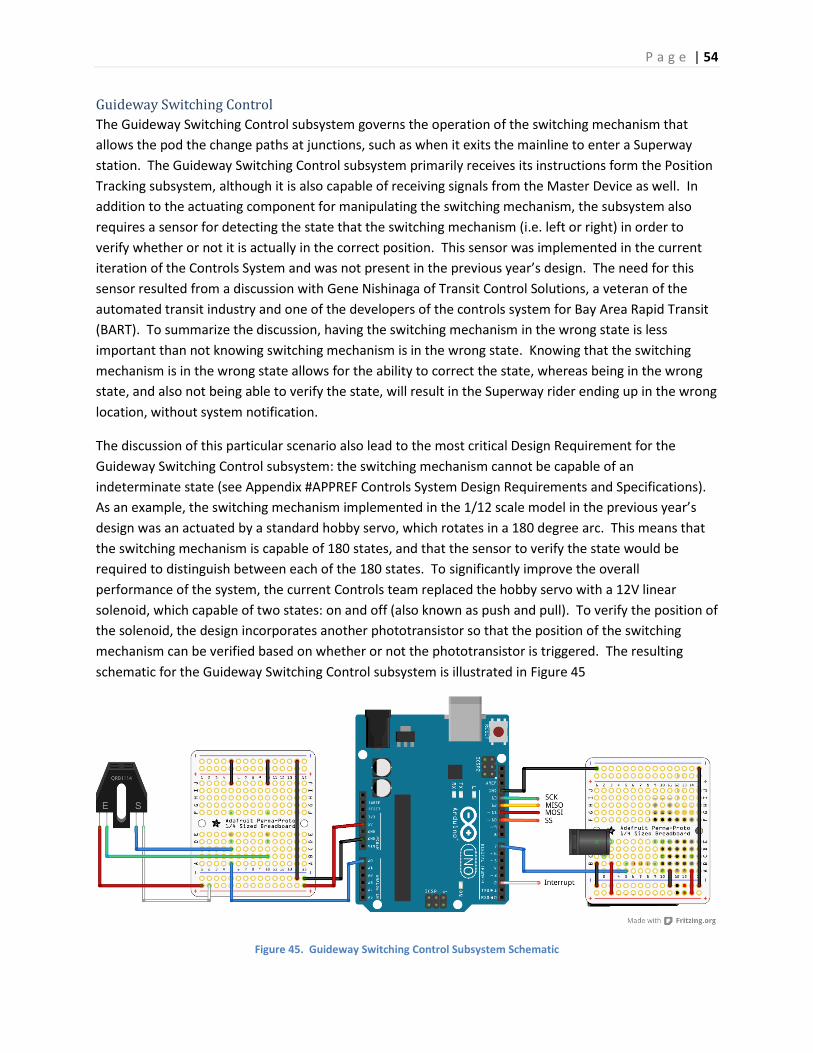
P a g e | 54
Guideway Switching Control
The Guideway Switching Control subsystem governs the operation of the switching mechanism that
allows the pod the change paths at junctions, such as when it exits the mainline to enter a Superway
station. The Guideway Switching Control subsystem primarily receives its instructions form the Position
Tracking subsystem, although it is also capable of receiving signals from the Master Device as well. In
addition to the actuating component for manipulating the switching mechanism, the subsystem also
requires a sensor for detecting the state that the switching mechanism (i.e. left or right) in order to
verify whether or not it is actually in the correct position. This sensor was implemented in the current
iteration of the Controls System and was not present in the previous year’s design. The need for this
sensor resulted from a discussion with Gene Nishinaga of Transit Control Solutions, a veteran of the
automated transit industry and one of the developers of the controls system for Bay Area Rapid Transit
(BART). To summarize the discussion, having the switching mechanism in the wrong state is less
important than not knowing switching mechanism is in the wrong state. Knowing that the switching
mechanism is in the wrong state allows for the ability to correct the state, whereas being in the wrong
state, and also not being able to verify the state, will result in the Superway rider ending up in the wrong
location, without system notification.
The discussion of this particular scenario also lead to the most critical Design Requirement for the
Guideway Switching Control subsystem: the switching mechanism cannot be capable of an
indeterminate state (see Appendix #APPREF Controls System Design Requirements and Specifications).
As an example, the switching mechanism implemented in the 1/12 scale model in the previous year’s
design was an actuated by a standard hobby servo, which rotates in a 180 degree arc. This means that
the switching mechanism is capable of 180 states, and that the sensor to verify the state would be
required to distinguish between each of the 180 states. To significantly improve the overall
performance of the system, the current Controls team replaced the hobby servo with a 12V linear
solenoid, which capable of two states: on and off (also known as push and pull). To verify the position of
the solenoid, the design incorporates another phototransistor so that the position of the switching
mechanism can be verified based on whether or not the phototransistor is triggered. The resulting
schematic for the Guideway Switching Control subsystem is illustrated in Figure 45
Figure 45. Guideway Switching Control Subsystem Schematic

P a g e | 55
Next Steps
Beyond the continued development and refinement of the current Control System setup, the main goals
for next semester emphasize improving the design to enhance expansion and scalability, and also to
leave a sufficient level of documentation so as to maximize the output of next year’s design iteration.
The first priority for next semester will be to modify the speed control and switching mechanism control
to communicate with the Master Device using controller area network (CAN) bus, instead of SPI. CAN
bus was originally developed for automotive use and is commonly used modern automotive braking
systems. Data transmission through CAN is differential, the signal is split at transmission, and when it is
merged at the termination point, the difference is taken between the two segments to produce a single
signal. Any noise experienced during transmission will be experienced by both segments, and will also
be cancelled out when the signal merged. The motors within the pod bogie will produce a significant
amount of electromagnetic noise, and using CAN will make the signals transferred between bogie and
the pod more secure. Currently, the pod houses the microcontrollers used for managing the speed
control and switching mechanism control, so modifying the microcontroller to use CAN bus serves as a
precaution in the event that the microcontrollers are moved to the bogie in the full-scale pod. The
BeagleBone Black features two CAN bus interfaces (Coley), however, utilizing the interfaces would
require that master device act as the speed controller and guideway switching controller, instead of
having two microcontrollers dedicated to the respective subsystems.
The second priority for the next semester will be to finalize the schematics for each subsystem and
subsequently scale down to the smallest possible microcontroller that will support all of the subsystems.
The Controls team is currently looking at the ATtiny line of microcontrollers produced by Atmel
Corporation ( (Atmel Corporation)). Scaling down the microcontrollers will allow the 1/12 scale model
Controls System to fit inside of an aesthetically-accurate cabin chassis fabricated on a 3D printer.
Scaling down the microcontrollers also provides the possibility of developing a BeagleBone Cape, an
expansion board that fits on top of a BeagleBone Black to provide extended functionality. A Cape is the
BeagleBone equivalent of an Arduino Shield. Developing a Cape for the 1/12 scale model will
dramatically reduce the amount of time required to produce additional pods for the test track, but only
if the Controls team gains access to machinery capable of fabricating circuit boards, such as a printed
circuit board (PCB) mill. Although a Cape design may be developed, it likely that the possibility to
fabricate the Cape will be dependent on the amount of funding generated in the coming semester.
To further improve the ability to expand the possibility of expanding the test track, the Controls team is
considering the possibility of switching over to off-the-shelf slot car track components. Once again, this
decision will likely be decided by the amount of funding acquired in the coming semester. While this
type of track setup will not provide an aesthetically accurate depiction of an elevated ATN system, it will
provide the ability to easily expand the test track and create more complex track layouts for testing
more sophisticated scenarios, with reduced material costs, construction time, and labor requirements.
The final goal for next semester is to investigate the possibility of transitioning to a one of the
Programmable System-on-Chip (PSoC) boards manufactured by Cypress International. The end result of
this goal would be two-fold: the first goal being to incorporate a board that is more industry-level and

P a g e | 56
less hobbyist, and the second is the possibility of leveraging the use of PSoC in the project to gain some
level of sponsorship from Cypress International. Cypress International is a well-known developer both
within Silicon Valley, and also internationally due to its versatile product offerings. Switching over to a
PSoC would potentially allow the Controls team to merge the multiple microcontrollers currently within
the Control System onto a single custom chip. The primary disadvantage to this is that using a custom
chip would dramatically impact the ability to produce additional test pods quickly, and could also be
more costly depending on the level of sponsorship, if any.
Solar Team How do you power a public transit system? Whether it is electricity or fuel, the energy to power these
systems are derived from carbon based fuels. SuperWay has decided to build a PRT system that
circumvents the use of these fuels. The design of the Spartan SuperWay includes a sustainable energy
source to power the system in the form solar power. Integrating a solar power system into the design
and construction of the Spartan SuperWay highlights SMSSV’s commitment toward sustainability and
the importance to offer the general public a clean form of transportation. The reasoning behind the
integration of a solar power system is the continued advancements in solar technology.
System Explanation
The main objective throughout this academic school year is to produce a full scale design and prototype
based on the design requirements and design specification developed in our design process. The design
specifications are the guiding principles for the overall function and performance of the final design. A
final design will consist of five major subsystems. The subsystems are listed in a cascading order that
designates the level of importance of each. It is also representative of the order in which each
subsystem is connected in a top down fashion.
Power Collection
Power Transfer
Frame
Guideway Mount
Tracking
The overall system design is mainly driven by four factors, safety, system efficiency, manufacturing and
assembly, and operation and maintenance. These factors also play a big part in the design of the
subsystems.
Power Collection
The solar panels, also called modules, are what generate the power used by the Spartan Superway. The
design of these is centered on their efficiency. The more efficient each individual module the better the
system performs. Clearly, efficiency will also affect cost, and as efficiency rises so does cost. The final
design is driven by this rise in cost of the modules. Cost analysis of the final design will show if the
module selected by last year’s solar team is compatible. The physical dimensions of the panels are set
by the manufacturer and also constrain the final design. But their high volume manufacturability is a
plus when the scale of the Spartan Superway is considered.

P a g e | 57
The mass of these modules drives the overall weight of the system, and adds a constraint to the design.
Especially relating to the forces exerted on the guideway mount subsystem. These rectangular shaped
modules, although heavy and large in size, still allows for a modular design. As advancements in solar
module design continues, lighter more efficient, and cheaper panels will give rise to a better design.
Power Transfer
So how does all the generated power get transferred to the bogie, cabin, station, and the electrical
power grid? The answer begins with a design that accounts for micro-inverter, central inverter, string
inverter, and grid-tie inverter technology. The power transfer subsystem design requires the use of
some type of inverter. Research on various manufactures shows a 95% efficiency of these varying
inverters. The final design for this subsystem addresses the operation and maintenance, and the all the
wiring required for the system. Major limiting factors considered for the systems, are heat generation
and islanding. The power transfer mechanism is designed to handle islanding via its integrated circuitry.
Also any heat generation from both the modules and the inverters is handled via the design of the
frame.
Frame
Although the frame’s only function is to hold the modules in place, its impact on the mass of the system
is great. The frame is designed to minimize overall weight of the using lightweight materials that are cost
effective. It is also designed to hold in place a conventional rectangular solar module. Also, the frame is
designed to integrate any wiring that is required for power transfer system efficiently and without the
need to add extra material. The material of the frame is designed to handle the weight of each module
and to equally distribute the weight and any forces due to wind, rain, and snow to the guideway mount.
Guideway Mount
When it comes to strength, durability, structural integrity, and life of the system, the guideway mount
design addresses these requirements. Designing for these characteristics is required to ensure a safe
and long lasting interface between solar power system and guideway. Because the system is designed to
transfer forces, moments, and stresses due to these to the guideway mount, this subsystem is robust.
And yet, it’s design is simple, small, and lightweight. It’s simplicity addresses the issue of
manufacturability and ease of installation. Also, durability is addressed because of the low number of
parts required. Structural integrity is another characteristic vital to the design of the guideway mount.
Maintaining a high safety standard for this subsystem drives the design toward one of simple geometry
to reduce stress concentrations and the number of critical points of failure. Lastly, because the guideway
mount is the interface between the guideway and the rest of the solar power system, it’s designed for a
life cycle greater than 25 years. The estimated life for all electronics and solar modules is 25 years based
on manufacture average specifications.
Tracking
Maximum efficiency drives the incorporation of solar tracking into the solar power system. To make the
design as efficient as possible, the control system is designed for optimized system performance. A
robust design is incorporated to ensure a durable drive unit and control unit. Tracking stability is a

P a g e | 58
required feature of the system, and is integrated into the design via the control system and the physical
design of the overall solar system.
System model
In order to evaluate the proper design, Pugh’s method is used to determine relative importance with
alternative design concepts in a basic decision matrix. This method is chosen instead of the robust
decision matrix due to the evaluation being used to determine preliminary design parameters which will
have more detail once a specific system is chosen. In this case four different design concepts for system
specification were taken into account as seen in the figures below.
Figure 46. Static Mount Concept
Table 4. Alternative Concepts for Design Consideration.

P a g e | 59
Figure 47. Single Axis Tracking on a Horizontal Axis.
Figure 48. Single Axis Tracking System on a Vertical Axis
Figure 49. Single Axis Tracking System on a Tilted Axis

P a g e | 60
The four design concepts chosen were evaluated with chosen parameters including relative importance
in order to decide which system is preferred based on the criteria shown in Table 2.
Table 5. Criteria for Basic Decision Matrix
Table 6. Basic Decision Matrix
Based on the evaluation of the design concepts in the basic decision matrix, the most important factor
taken into consideration is the manufacturability and power generation efficiency of the solar mount.
With these two factors along with the other parameters chosen, the results indicate that a single-axis
solar tracking system on a vertical axis is the best design concept to be used when considering the solar
panel mount design. This design concept seems to be the easiest system to design, manufacture and
maintain because of less moving parts in this type of single-axis tracking system. The following figures

P a g e | 61
show 3 dimensional models of the final concepts evaluated. Figure 7 is the final concept chosen for
further design and analysis.
Figure 50. 3D cad design of initial brainstorm session designs.

P a g e | 62
Figure 51. 3D cad design cut out of single axis system from brainstorm sessions.
Figure 52. 3D cad design of single axis tracker concept derived from brainstorm sessions.

P a g e | 63
Figure 53. 3D cad design of horizontal single axis tracker derived from brainstorm session.
Figure 54. 3D cad design of tilted tracker derived from brainstorm session.
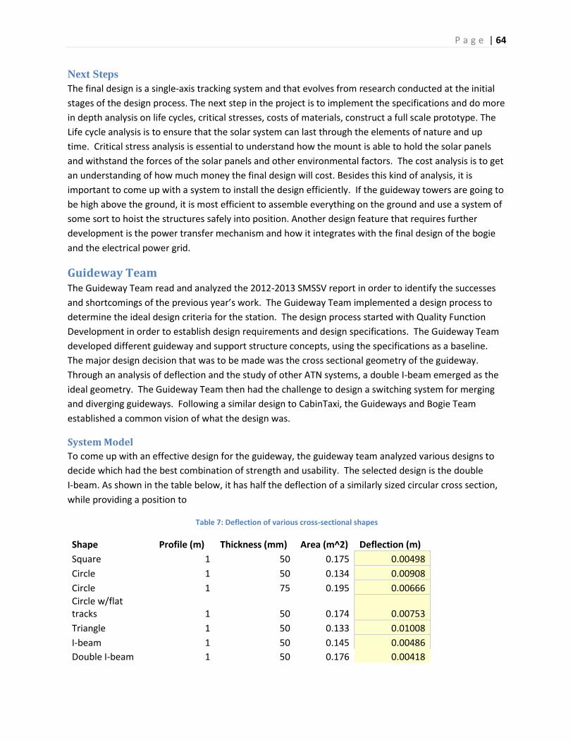
P a g e | 64
Next Steps
The final design is a single-axis tracking system and that evolves from research conducted at the initial
stages of the design process. The next step in the project is to implement the specifications and do more
in depth analysis on life cycles, critical stresses, costs of materials, construct a full scale prototype. The
Life cycle analysis is to ensure that the solar system can last through the elements of nature and up
time. Critical stress analysis is essential to understand how the mount is able to hold the solar panels
and withstand the forces of the solar panels and other environmental factors. The cost analysis is to get
an understanding of how much money the final design will cost. Besides this kind of analysis, it is
important to come up with a system to install the design efficiently. If the guideway towers are going to
be high above the ground, it is most efficient to assemble everything on the ground and use a system of
some sort to hoist the structures safely into position. Another design feature that requires further
development is the power transfer mechanism and how it integrates with the final design of the bogie
and the electrical power grid.
Guideway Team The Guideway Team read and analyzed the 2012-2013 SMSSV report in order to identify the successes
and shortcomings of the previous year’s work. The Guideway Team implemented a design process to
determine the ideal design criteria for the station. The design process started with Quality Function
Development in order to establish design requirements and design specifications. The Guideway Team
developed different guideway and support structure concepts, using the specifications as a baseline.
The major design decision that was to be made was the cross sectional geometry of the guideway.
Through an analysis of deflection and the study of other ATN systems, a double I-beam emerged as the
ideal geometry. The Guideway Team then had the challenge to design a switching system for merging
and diverging guideways. Following a similar design to CabinTaxi, the Guideways and Bogie Team
established a common vision of what the design was.
System Model
To come up with an effective design for the guideway, the guideway team analyzed various designs to
decide which had the best combination of strength and usability. The selected design is the double
I-beam. As shown in the table below, it has half the deflection of a similarly sized circular cross section,
while providing a position to
Table 7: Deflection of various cross-sectional shapes
Shape Profile (m) Thickness (mm) Area (m^2) Deflection (m)
Square 1 50 0.175 0.00498
Circle 1 50 0.134 0.00908
Circle 1 75 0.195 0.00666
Circle w/flat tracks 1 50 0.174 0.00753
Triangle 1 50 0.133 0.01008
I-beam 1 50 0.145 0.00486
Double I-beam 1 50 0.176 0.00418

P a g e | 65
Load 16000 kg Young's Modulus 2.1E+11 Pa Length 20 m
As shown in the figure below, the chosen design is similar to a traditional I-beam, with a two vertical
beams to provide additional protection against torsional stresses. The interior section provides a
location for the various electrical components that are required along the guideway. This includes the
power conduits and any communication channels as required by the control team.
Figure 55: Double I-beam profile
One concern associated with the chose cross section is the difficulty in designing the track switching
sections. As demonstrated in the following figure, certain cutouts are required to allow the bogie to
select which track to continue riding along. Due to the geometry of the switching section, extra
supports are required on the outside of the guideway to support the bogie when the wheels traverse
the gaps in the bottom of the I-beam. The system always allows the bogie to have four wheels in contact
with the guideway at all time.

P a g e | 66
Figure 56: Sample track section including switch section
Next Steps
During the winter break, the Guideway Team will create a simply, scaled, wooden model of the
proposed switching system as a proof of concept. In addition, the Team will complete much of the
mathematical engineering analysis in order to determine the dimensions that the guideway and support
structures need to be. These dimensions will determine the appropriate geometry to insure that the
system follows specifications and other structural requirements.
At the current state in the design process, it is unclear exactly how the system will be represented.
There are three proposed modeling representations. The first is a full scale, single length of guideway
that supports a cabin that people can actually get into. The model will be constructed on a flatbed
trailer, this design allows the model to move to different locations quickly and easily, and will help
promote the idea and concepts of ATN. The second system is similar to the first in that it will be mobile,
and will be transported with a flatbed trailer. However, the second model will be full scale, will be
quickly erected on site, and will stand at the full height of the proposed system. This will allow people to
get a better idea of how the system will appear from ground level if it is constructed. The final proposed
model is a full scale system that is built on a site. The full scale model will consist of a straight section
and a switching section. The guideway will support a full-scale cabin that may or may not allow
passengers to enter. This design will be used to show interested individuals the functionality of
switching mechanism and will encourage people to support the ATN.
Once a model proposal is decided as the model to build, the Guideway Team will create a document
that highlights the contributions that can be made from Professor McMullen’s Steel Design class. The
Steel design students will likely assist in the design of the support structures for the guideway, which
could be an actual support modeled as would be built in the system, or a truss structure to support the
model without the additional strength that would be required in the actual system. In addition another
document will be created that will explain the needs that the Guideway Team has for the Industrial
Design students. The Industrial design students will likely design an aesthetic cover for the guideway
that will merge in a visually appealing way to the cabin design and the station design.

P a g e | 67
During the Spring Semester, the Guideway Team will finalize any mathematically analysis that needs to
be completed, and from those analyses develop a final solid model of the system. The Guideway Team
will work with the other mechanical engineering sub teams, as well as the civil engineers from Professor
McMullen’s Steel Design class and the Industrial Design Students to create an appealing and functional
full-scale model of the Guideway.
Human Centered Design Team
What is Human Centered Desgin?
Human-Centered Design, design that puts users first, came into the conversation of the Spartan
Superway project early this semester when the students identified the importance of understanding the
needs of the Spartan Superway riders. The idea that we should put the riders at the forefront of our
design process was new to the project so we began by compiling a list of the assumptions that our
teams, both past and present, had made about our ATN and public transit in general. Those assumptions
were: that people want a change to current public transportation; that people value Safety, Reliability,
Efficiency, Cost, Privacy, and Comfort in that order; that inefficiency is the biggest reason people choose
their cars over public transit; that people see the value in a Solar Powered System; that NIMBY (Not in
My back Yard) attitudes will be a challenge in zoning the ATN; and, that people are comfortable with
riding in a suspended transportation system.
Human-centered Design begins with gaining a deep understanding of our users and not making
decisions based on assumptions about them. Therefore, our team chose to test some of those
assumptions with field research. We decided the best strategy was to conduct two sets of user research:
the first is a round of in-person, one-on-one interviews; the second is an online survey intended to
gather a larger sample of data. We began by developing interview questions for a short field survey for
each student to conduct so that everyone would have the opportunity to gain insight and get direct
feedback from the public. We gave each student a twenty-five question survey to conduct with three
people, two of which they encountered on or waiting for public transit. (See questions in Appendix
APPREF HCD Survey 1 Data and Results). Instructions for Surveying:
1. Present yourself as an SJSU Engineering student conducting a survey on Public
Transportation for your senior project.
2. Ask the potential surveyee if they would like to participate in a short, anonymous survey.
Make them feel comfortable.
3. Ask the first 20 questions. You may voice record their responses with their consent, but only
in addition to hand writing their responses in a note pad/separate paper. You will have to
scribble and be fast, but it is the best way to get the insight you need from each person.
Capture real quotes and what they actually say instead of trying to interpret what they say
in your notes.
4. Show them the picture on page 2 and give them the short explanation written above it.
Then continue on to the next page for the last 6 questions about the picture.
5. If they were particularly helpful or had interesting responses, ask if they would like to
provide their name and email for us to contact them in the future with any further follow-up

P a g e | 68
questions. In your notes, write down where you are and who you are surveying, i.e.: man on
the bus #56, student at the Cal-Train station, etc...
6. Remember the point of this survey isn't to get answers it's to gain insight and a deep
understanding of our users.
The Human-Centered Design team then gathered the data and compiled it in a series of graphs, but
most important was each student’s individual experience of conducting the field research and gaining
insight from the population.
Conducting this in person survey was very insightful experience for the entire team because it allowed
the students to understand and get a deeper understanding for what and how the user felt about public
transportation.
The demographics of the survey came out to be 55% male and 45% female, of which 44% take public
transit every day. The results showed that a majority of riders had the same opinions about current
public transportation. The benefits most rider’s felt they gained from taking public transportation is
either to save money; not deal with the hassle of driving which includes dealing with traffic and parking;
as well as being able to have personal time to do work, listen to music, or read.
However, despite these benefits riders are slowly getting frustrated with a few aspects of public
transportation, which SMSSV plans to address. The most important problems riders want to see
addressed are the rising cost of public transit, the inefficiency especially during rush hour, and the
overcrowding. Riders have been worried that soon the cost and time to take public transit will no longer
provide as a better alternate solution to driving. The overcrowding of stations and trains and the cost to
ride is becoming comparable to traffic on the road and high price of gas. Riders feel like the
overcrowding can be resolved by having more trains/buses available that also come more frequently.
SMSSV’s solution to these issues was presented to riders to get their opinion of such a system. The
overall response was positive and reassuring as one person stated, “Pretty awesome as a new solution
to transportation, using higher ground for more space, hopefully government will pursue this
technology.” Although 78% of interviewees have never heard of a system such as this 86% of them said
they would feel comfortable using and riding this form of public transportation.
After completing the one-on-one field interviews, we implemented our Online based, twenty question
survey in order to expand on some of our interview questions as well as understand the community’s
priorities for public transit. Once we built this survey, we used Facebook, email, and other social media
devices to gather responses. We understood that this would place the bias of a younger demographic on
our results (most of our survey takers were 18-34 years old), but we determined it was the best method
within our means to procure a larger amount of responses to get better data. (See questions in
Appendix N: HCD Survey 1 Data and Results).

P a g e | 69
As a result of the conducting the more data driven survey Figures 57 and 58 illustrates that reliability is a
main concern for riders. This shows that not only are riders currently not pleased with how public
transit operates today, but also shows where SMSSV can gain a competitive advantage.
Figure 57
Figure 58
02468
1012141618
When it comes to Public Transportation how important is each of the following to you? Rate each from 1-5
% who rated each"Extremely Important"
0
50
100
150
200
250
When it comes to Public Transportation how important is each of the following to you? Rate each from 1-5
1.Not Important
2.Less Important
3.Important
4.Very Important
5.Extremely Important

P a g e | 70
By making the ATN system more reliable SMSSV will be able to convert a majority of the approximately
55% occasional riders as shown in Figure 59, to more frequent users.
Figure 59
Cutting down on the travel 2 hour travel time by 31% of riders, shown in Figure 60 would also help
convert and maintain repeat riders of the SMSSV system, as Figure 61 shows that 53% of riders strongly
agree that they would switch to public transportation if it were as convenient as fast as their car.
0.0%
5.0%
10.0%
15.0%
20.0%
25.0%
30.0%
35.0%
Never 1-5 times ayear
1-5 times amonth
2-5 days aweek
Always
How often do you take public transportation?
Never
1-5 times a year
1-5 times a month
2-5 days a week
Always

P a g e | 71
Figure 60
Figure 61
Based on Figure 62 roughly 80% of the demographic surveyed is of age 34 and under and from Figure 63
50% make $50,000 or less so rising public transit fares are definitely a deterrent since there is quickly
becoming no clear benefit over driving.
23.4%
33.9% 31.8%
10.4%
0.5%
0.0%
5.0%
10.0%
15.0%
20.0%
25.0%
30.0%
35.0%
40.0%
0-15 minutes 16-30 minutes 31- 60 minutes 1-2 hours more than twohours
How long is your daily commute one-way?
1% 1% 1% 8% 11% 26% 53% 0.00%
10.00%
20.00%
30.00%
40.00%
50.00%
60.00%
I would switch to public transit if it was as convenient and fast as my car.

P a g e | 72
Figure 62
Figure 63
0.0%
46.9%
41.7%
4.2% 5.7%
1.6% 0.0% 0.0%
0.0%
5.0%
10.0%
15.0%
20.0%
25.0%
30.0%
35.0%
40.0%
45.0%
50.0%
under 18 18 to 24 25 to 34 35 to 44 45 to 54 55 to 64 65 to 74 75 or older
What is your age?
29.2%
20.8% 18.2%
9.9% 13.0%
5.7%
2.1% 1.0%
0.0%
5.0%
10.0%
15.0%
20.0%
25.0%
30.0%
35.0%
What is your approximate average household income?
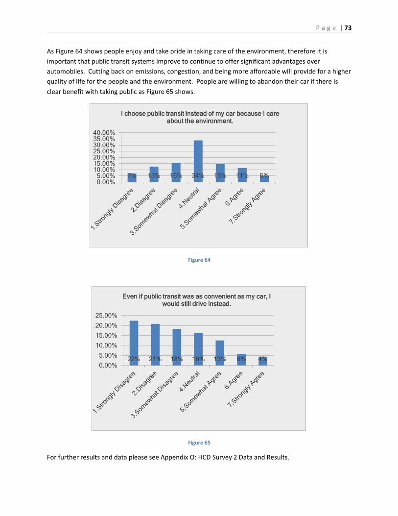
P a g e | 73
As Figure 64 shows people enjoy and take pride in taking care of the environment, therefore it is
important that public transit systems improve to continue to offer significant advantages over
automobiles. Cutting back on emissions, congestion, and being more affordable will provide for a higher
quality of life for the people and the environment. People are willing to abandon their car if there is
clear benefit with taking public as Figure 65 shows.
Figure 64
Figure 65
For further results and data please see Appendix O: HCD Survey 2 Data and Results.
7% 13% 16% 34% 15% 11% 5% 0.00%5.00%
10.00%15.00%20.00%25.00%30.00%35.00%40.00%
I choose public transit instead of my car because I care about the environment.
22% 21% 18% 16% 13% 6% 4% 0.00%
5.00%
10.00%
15.00%
20.00%
25.00%
Even if public transit was as convenient as my car, I would still drive instead.

P a g e | 74
Next Steps
Now that the HCD team has been able to gather a good amount of data over the last few months, the
next step in the process will be to begin to analyze the data and determine any trends or principally
pressing points that should be addressed in collaboration with the other design teams. We would also
like to get a better idea of who the possible consumer would be for this new form of transportation.
Looking into age and income demographics could provide as a solid starting point toward this goal. But
to help understand this graphic more, a plan must be devised in how to reach more people, as well as
educate them on our project and this technology that we are trying to help promote and provide to the
masses. There have been talks amongst the HCD team of finding a way to hold some sort of educational
campaign and use the data we have gathered thus far to determine main talking points and highlights of
our system.
Also, with the data acquired, we can begin designing for what the user experience of the Spartan
Superway should feel like. This process will be helping to design every possible interface that the
consumer will eventually encounter as a part of using the system. The particular areas that the HCD
team would be design toward include, but are not limited to; first mile problems (how the user will get
from their initial location to the station), the process of determining the route of a pod, how the user
will purchase tickets, what the experience inside of the station should feel like, the experience of the
expectations and attributes inside of the cabin for the consumer (as well as legally), and last mile
problems (how the user will transport from the station to their final destination).
Station Team The Station Team read and analyzed the 2012-2013 SMSSV report in order to identify the successes and
shortcomings of the previous year’s work. The Station Team implemented a design process to
determine the ideal design criteria for the station. The design process involved only a single stage
design development, Quality Function Development (QFD), and did not consist of a concept generation
step, or a concept evaluation step. Omitting the concept steps allowed the industrial designers to
conceptualize creative designs based on the requirements and specifications developed during the QFD
process.
The Station Team developed the design requirements while considering a specific set of customers. The
requirements considered the City of San Jose, Riders, both disabled and non-disabled, foreign language
speakers, and occupants of local real estate.
System Model
The Station Team did not generate a system model of the Station. The Station Team is deferring to the
Industrial Designers to generate concepts as per the requirements, specifications, and functions that the
Station Team developed in the design process.
Next Steps
The Station Team will work with the other mechanical engineering sub system teams, and the Industrial
Design students to develop an aesthetic, and functional station that adheres to the building codes
established by the government bodies as well as the specifications established in the Station Team

P a g e | 75
design process. The Station Team will provide as much assistance as is necessary to the industrial design
students to insure the station design insures functionality and human safety.
Tentative Future Schedule
As a tentative guide to where the project will be heading moving forward below is a Gnatt chart that
shows SuperWay’s preliminary schedule:

P a g e | 76
P a g e | 77
References n.d. 5 December 2013. <http://www.northerntool.com/shop/tools/product_200511868_200511868>.
n.d. 5 December 2013. <http://www.northerntool.com/shop/tools/product_200466863_200466863>.
n.d. 4 December 2013. <http://www.northerntool.com/shop/tools/product_21759_21759>.
ABB Motion Control. LMAC AC Linear Induction Motor. 2012.
<http://www.baldormotion.com/products/linearproducts/lmac.asp>.
Aluminum Plate. n.d. 3 December 2013.
<http://www.metalsdepot.com/products/alum2.phtml?page=plate>.
American Society of Civil Engineers. Automated People Mover Standards. Reston, Virginia: American
Society of Civil Engineers, 2008.
Atmel Corporation. "ATmega328P." 7 December 2013. Atmel Corporation - Microcontrollers, 32-bit, and
touch solutions. <http://www.atmel.com/Images/doc8161.pdf>.
—. "ATtiny85." 7 December 2013. Atmel Corporation. <2013>.
Auto Zone. Doorman/Hood Latch. 2013. <http://www.autozone.com/autozone/parts/_/N-
8ij1i?itemIdentifier=884471_0_4169_>.
Baldor. Products: AC Motors. 2013.
<http://www.baldor.com/products/detail.asp?1=1&page=1&catalogonly=1&catalog=EM4107T
&product=AC+Motors&family=Premium+Efficient|vw_ACMotors_PremiumEfficiency&phase=3
&hp=25-28&rpm=2800-3600&enclosure=TEFC&winding=09WGY357&rating=40CMB-CONT#>.
City of San Jose. City of San Jose Department of Transportation Geometric Design Guidlines. August
2012. <http://www.sanjoseca.gov/DocumentCenter/View/4384>.
—. Envision San Jose 2040 General Plan, Section 3.3 Noise and Vibration. June 2011.
<http://www.sanjoseca.gov/DocumentCenter/View/2194>.
Coley, Gerald. "BeagleBone Rev A6 System Reference Manual." 9 May 2012. BeagleBoard.org.
<http://beagleboard.org/static/beaglebone/latest/Docs/Hardware/BONE_SRM.pdf>.
Cytron Technologies. "SN-HC-SR04 - Ultrasonic Ranging Module." 7 December 2013. Cytron
Technologies. <http://cytron.com.my/viewProduct.php?pcode=SN-HC-
SR04&name=Ultrasonic%20Ranging%20Module>.
Fairchild Semiconductor. "BSS138 N-Channel Logic Level Enhancement Mode Field Effect Transistor."
October 2005. Fairchild Semiconductor. <http://www.fairchildsemi.com/pf/BS/BSS138.html>.

P a g e | 78
Hamilton. PolySoft Wheels. 2013.
<http://www.hamiltoncaster.com/Wheels/Polyurethane_Wheels/3_8_Thick_Treads/PolySoft_
Wheels.aspx>.
—. Ultralast Wheels. 2013.
<http://www.hamiltoncaster.com/Wheels/Polyurethane_Wheels/3_8_Thick_Treads/Ultralast%
E2%84%A2_Wheels.aspx>.
Homefacts. San Jose, CA Earthquake Report. 1 December 2013.
<http://www.homefacts.com/earthquakes/California/Santa-Clara-County/San-Jose.html>.
How Linear Induction Motors Work. n.d. 4 December 2013. <http://www.force.co.uk/linear-
motors/how-linear.php>.
Jameco Electronics. "Jameco ReliaPro HNGH12-1324Y-R." 6 Decemeber 2013. Jameco Electronics.
<http://www.jameco.com/Jameco/Products/ProdDS/162191.pdf>.
Linear Motors and Stages. n.d. 4 December 2013.
<http://www.baldor.com/products/linear_motors.asp>.
National Oceanic and Atmospheric Administration. Station Name: CA San Jose. 1 December 2013.
<ftp://ftp.ncdc.noaa.gov/pub/data/normals/1981-
2010/products/station/USC00047821.normals.txt>.
Paige, T. Automated transit network feasibility evaluation: San Jose Mineta International Airport, San
Jose, CA (Report No. ATR-2012(5629)-1). San Jose, CA: The Aerospace Corporation, 2012.
Sidner, Arthur E. "ATC Publications Home Page." 2013. ATC Publications.
<http://www.atcpublications.com/Sample_pages_from_FDG.pdf>.
STMicroeletronics. "LSM303DLHC Ultra compact high performance e-compass." 6 December 2013.
STMicroelectronics. <http://www.st.com/st-web-
ui/static/active/en/resource/technical/document/datasheet/DM00027543.pdf>.
Woodford, Chris. "How do linear motors work? - Road Runner Home Pages." 4 July 2013. Explain That
Stuff. <http://www.explainthatstuff.com/linearmotor.html>.
BART. (n.d.). New Train Project. Retrieved from www.bart.gov:
http://www.bart.gov/about/projects/cars/new-features
SMSSV. (2012). ME195C Report. San Jose State University, Mechanical Engineering.
Ultra Global PRT. (n.d.). Vehicle Features. Retrieved from www.ultraglobalprt.com:
http://www.ultraglobalprt.com/wp-content/uploads/2011/08/PDF_Vehicle-features.pdf

P a g e | 79
Appendix A: Bogie Design Requirements & Specifications Bogie Design Goals and Objectives
Design Requirements
1. The bogie must be able to suspend the pod cabin.
1.1. The bogie should be able to suspend the cabin’s weight in both dynamic and static conditions.
1.1.1. The bogie must be able to suspend the mass of the cabin during cornering at specified
speeds and radii.
1.1.2. Bogie must be able to suspend the mass of the cabin over crests and dips in the guideway.
1.2. The bogie must be able to mount to the specified cabin top surface and frame design.
2. The bogie must be able to travel and navigate through the Superway guideway network.
2.1. The bogie must be able to interface with power conduits placed along the guideway.
2.1.1. Bogie must interface with power conduits during all operations, including guideway
switching.
2.1.2. Power from conduit must be transmitted to cabin.
2.2. The bogie must have variable acceleration and speed capabilities up to its performance targets.
2.3. The bogie must be able to navigate guideway corners.
2.3.1. Bogie must be able to navigate the tightest specified/possible radii.
2.3.2. Bogie must smoothly ride around corners (no crashing into guideway walls).
2.4. The bogie will be able to switch between guideways.
2.4.1. Bogie will not be jolted when switching guideways.
2.4.2. Switch will not be capable of making an “indecisive guideway selection”.
2.5. The bogie must be able to climb and descend maximum specified grades.
2.6. The bogie must be able to coordinate with station procedures.
2.6.1. Bogie must operate at a reduced speed and stop and accordingly.
2.6.2. Bogie must be able to hold steady during boarding and offloading at stations.
2.7. The bogie must provide a comfortable ride.
2.7.1. Vibration must be dampened/minimized within the guideway interface.
2.7.2. Vibration must be dampened/minimized at the cabin interface.
2.7.3. Bogie must allow the pod to bank during cornering.
3. The bogie must be able to perform emergency operations.
3.1. The bogie must be able to perform an emergency stop when prompted.
3.1.1. Bogie must have an electrical cut off/safety switch.
3.1.2. Bogie must have a manual emergency braking system.
3.2. The bogie must be able to interface with emergency power or tow vehicle.
3.3. The bogie must maintain basic functionality during a power loss.
3.3.1. The guideway switching mechanism state must be unaffected by a power loss.
3.3.2. The manual emergency braking system must function during a power loss.
4. The bogie must be optimized for the operating efficiency.
4.1. The bogie must be able to consume as little as power to meet speed and acceleration targets.
4.2. The bogie must be able to recapture braking energy during normal operation.
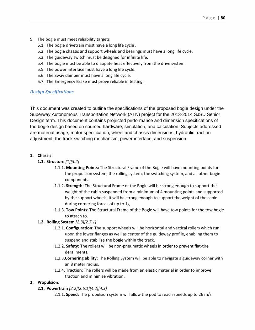
P a g e | 80
5. The bogie must meet reliability targets
5.1. The bogie drivetrain must have a long life cycle .
5.2. The bogie chassis and support wheels and bearings must have a long life cycle.
5.3. The guideway switch must be designed for infinite life.
5.4. The bogie must be able to dissipate heat effectively from the drive system.
5.5. The power interface must have a long life cycle.
5.6. The Sway damper must have a long life cycle.
5.7. The Emergency Brake must prove reliable in testing.
Design Specifications
This document was created to outline the specifications of the proposed bogie design under the
Superway Autonomous Transportation Network (ATN) project for the 2013-2014 SJSU Senior
Design term. This document contains projected performance and dimension specifications of
the bogie design based on sourced hardware, simulation, and calculation. Subjects addressed
are material usage, motor specification, wheel and chassis dimensions, hydraulic traction
adjustment, the track switching mechanism, power interface, and suspension.
1. Chassis:
1.1. Structure [1][3.2]
1.1.1. Mounting Points: The Structural Frame of the Bogie will have mounting points for
the propulsion system, the rolling system, the switching system, and all other bogie
components.
1.1.2. Strength: The Structural Frame of the Bogie will be strong enough to support the
weight of the cabin suspended from a minimum of 4 mounting points and supported
by the support wheels. It will be strong enough to support the weight of the cabin
during cornering forces of up to 1g.
1.1.3. Tow Points: The Structural Frame of the Bogie will have tow points for the tow bogie
to attach to.
1.2. Rolling System [2.3][2.7.1]
1.2.1. Configuration: The support wheels will be horizontal and vertical rollers which run
upon the lower flanges as well as center of the guideway profile, enabling them to
suspend and stabilize the bogie within the track.
1.2.2. Safety: The rollers will be non-pneumatic wheels in order to prevent flat-tire
derailments.
1.2.3.Cornering ability: The Rolling System will be able to navigate a guideway corner with
an 8 meter radius.
1.2.4. Traction: The rollers will be made from an elastic material in order to improve
traction and minimize vibration.
2. Propulsion:
2.1. Powertrain [2.2][2.6.1][4.2][4.3]
2.1.1. Speed: The propulsion system will allow the pod to reach speeds up to 26 m/s.
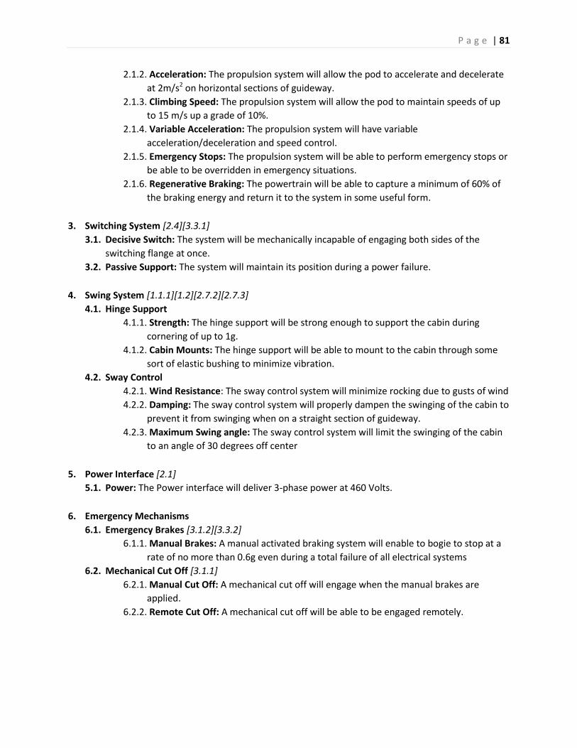
P a g e | 81
2.1.2. Acceleration: The propulsion system will allow the pod to accelerate and decelerate
at 2m/s2 on horizontal sections of guideway.
2.1.3. Climbing Speed: The propulsion system will allow the pod to maintain speeds of up
to 15 m/s up a grade of 10%.
2.1.4. Variable Acceleration: The propulsion system will have variable
acceleration/deceleration and speed control.
2.1.5. Emergency Stops: The propulsion system will be able to perform emergency stops or
be able to be overridden in emergency situations.
2.1.6. Regenerative Braking: The powertrain will be able to capture a minimum of 60% of
the braking energy and return it to the system in some useful form.
3. Switching System [2.4][3.3.1]
3.1. Decisive Switch: The system will be mechanically incapable of engaging both sides of the
switching flange at once.
3.2. Passive Support: The system will maintain its position during a power failure.
4. Swing System [1.1.1][1.2][2.7.2][2.7.3]
4.1. Hinge Support
4.1.1. Strength: The hinge support will be strong enough to support the cabin during
cornering of up to 1g.
4.1.2. Cabin Mounts: The hinge support will be able to mount to the cabin through some
sort of elastic bushing to minimize vibration.
4.2. Sway Control
4.2.1. Wind Resistance: The sway control system will minimize rocking due to gusts of wind
4.2.2. Damping: The sway control system will properly dampen the swinging of the cabin to
prevent it from swinging when on a straight section of guideway.
4.2.3. Maximum Swing angle: The sway control system will limit the swinging of the cabin
to an angle of 30 degrees off center
5. Power Interface [2.1]
5.1. Power: The Power interface will deliver 3-phase power at 460 Volts.
6. Emergency Mechanisms
6.1. Emergency Brakes [3.1.2][3.3.2]
6.1.1. Manual Brakes: A manual activated braking system will enable to bogie to stop at a
rate of no more than 0.6g even during a total failure of all electrical systems
6.2. Mechanical Cut Off [3.1.1]
6.2.1. Manual Cut Off: A mechanical cut off will engage when the manual brakes are
applied.
6.2.2. Remote Cut Off: A mechanical cut off will be able to be engaged remotely.

P a g e | 82
Appendix B: Bogie House of Quality

P a g e | 83

P a g e | 84
Appendix C: Powertrain Calculations
FORCE REQUIRED FOR ACCELERATION
F=ma, a=2m/s/s
F=2312 N
m=F/a= 1156 kg.
Acceleration targets should be met by LIM if mass of podcar is less than 1156 kg.
POWER REQUIRED FOR HILL CLIMB
(
)
(
)
40 mph = 64
Rise = (64
)*(sin5.71)
Rise = 6.37 km = 6,370 m
PE = mgh = (1,250 kg)*(9.8)*(6,370m)
PE=78,032,500 J
Power =
Power = 21,675.7 W
21,675.7*
= 29 HP
Total Power Necessary = 25+29 = 54 HP; 25HP is base power needed for flat guideway

P a g e | 85
Appendix D: Previous Concepts The Following is a document which describes the three iterations of bogie design which were explored
by the bogie team prior to selecting the prime design.
The Conventional Bogie Design
Advantages
The conventional bogie design is currently state of the art
Design is stable at rest with the cabin detached
Uses fewest number of wheels, is relatively simple in design
Disadvantages
Restricted turning radius:

P a g e | 86
If the guideway turns too sharply, the wheels will ride off the side of the track, and the distance from
center of the side of the bogie will approach (or collide with) the wall of the guideway.
Design requires drive wheel slipping for turning: In order for the bogie to go around a corner, the traction wheels (which are also the support wheels)
must be forced to slip in order to travel along a vector which is not parallel with the plane of the wheel.
Shorter moment arm for resisting wheel lift under acceleration torque:
When the bogie accelerates the cabin, the acceleration force and the inertial force create a moment
(Figure 1a). This acceleration creates wheel lift (shown in Figure 1b). This imbalances the normal force
on the front and rear axles. The result of that is a moment caused by the normal force and by gravity,
show in Figure 2a.
The gravitational and normal forces are determined by the mass of the bogie-cabin system, but the
moment arm length is determined by the geometry of the bogie. Compared to the other two designs in

P a g e | 87
this document, the conventional bogie design has the least resistance to wheel lift due to acceleration
torque.
Cornering causes traction imbalance:
When the bogie and cabin follow a curve in the guideway, there is a moment which causes the outside
wheels of the bogie to lift off the track if the moment is great enough to overcome the moment caused
by gravity and the normal force of the inside wheel. Even in situations where the wheel does not lift, this
represents a traction imbalance which could result in wheel spin or in a torque vectoring effect.
(note that the terminology in the above diagram “loss of traction” is not technically correct, because
inside wheel would be gaining close to double the traction it would ordinarily have).
Requires separate cabin swing system: As agreed upon by the cabin and human centered design teams, in order for a cabin to comfortably
travel at speed along a curved stretch of guideway, it must bank. Conventional bogies must employ a
hinge system to suspend the cabin in order to allow this to happen.
Guiding arms required to keep the bogie centered:

P a g e | 88
For a small scale model, the bogie can navigate down the guideway by colliding with the sides of the
guideway to keep it on course. In practice, simply allowing the bogie to run into the guideway wall will
not only cause discomfort from the passengers, but will cause wear on parts and equipment. To solve
this problem, there must be sprung guiding arms with rollers which apply force to the bogie when it
approaches a wall so that it doesn’t collide with it. This adds complexity and cost.
The Split Bogie Design
Advantages
No drive wheel slipping during turning
Half the weight per support (thinner cabin supports)
Improved turning radius over conventional design:

P a g e | 89
By using two shorter bogies with only two wheels each, traveling down a curved guideway becomes
much more ideal. The minimum turning radius can be greatly shortened, theoretically to half the
distance between the bogies. It also eliminates the problem of the bogie hitting the wall of the
guideway.
Long moment arm for resisting wheel lift under acceleration torque:

P a g e | 90
As discussed above, acceleration forces create a moment which can cause wheel lift. The moment
caused by gravity and the normal force of the wheels on the track is greater in the split bogie design
because the moment arm is longer.
Disadvantages
Unstable at rest without the cabin to connect the two bogies together: Because each bogie has only two wheels, it is not stable on its own. This means a different bogie design
would have to be developed as a tow bogie, and if any bogie became detached from the cabin, a tow
bogie couldn’t simply push it out of the way.
Cabin weight must be bearing loaded: Because the two bogies don’t always face the same direction (such as when going around a corner), they
also cannot face the same direction as the cabin. The split bogie design requires large bearings which
allow the bogies to rotate with respect to the cabin. These bearings will need to be hefty enough to
support the weight of the cabin.
Twice the power rail contact/steering/guiding components are required
Cornering causes traction imbalance (like conventional bogie design)
Requires separate cabin swing system (like conventional bogie design)
Requires guiding arms (like conventional bogie design)
Power must be cut at junction to avoid torque steer: When one of the bogies passes over a junction, all the traction on one wheel is momentarily lost. This
means that the only force is coming from one wheel, which can have a torque steering effect. This could
cause the bogie to rotate inside the guideway.
Bogie can twist in track:

P a g e | 91
A possible failure scenario occurs if one of the bogies, which can rotate with respect to the cabin,
rotates 90 degrees. This would wedge the wheels in the guideway, halting the bogie. If this happened at
high speed, the bogie could be ripped apart, and support of the cabin could be lost. Note that this can
only occur if the guiding arms fail.

P a g e | 92
Tubular Bogie Design
Advantages
Cabin swing possible with rigid design:
The tubular design allows the bogie to rotate in the guideway, which in turn allows the cabin to swing
without a hinge. In addition to simplifying the hinging design, it also makes control of the swinging
easier. At stations, the gap in the guideway could narrow, preventing the cabin from swinging. Traction
force on the bogie wheels resists (and therefore dampens) banking naturally, and a roller-piston system
with non-newtonian fluid can be used between the cabin support column and the edge of the guideway.
Cornering cannot cause traction imbalance: With the tubular design, all support and drive wheels are always in contact with the guideway,
preventing any form of traction imbalance as seen on the other designs.

P a g e | 93
Traction wheel can be pneumatic tire: Pneumatic tires benefit from greater traction, but in the case where the bogie is supported by the drive
wheel, a pneumatic tire becoming flat could cause a derailment. With the tubular design, a flat drive
wheel poses a much lower threat.
Adjustable Rolling Resistance: Because the support wheels do not need to propel the bogie, they can be firm and provide low rolling
resistance without sacrificing traction. The piston which adjusts the pressure of the traction wheel can
adjust to varying situations. Where more traction is needed, it can press up against the roof of the
guideway. When less traction is needed, it can provide less force, reducing rolling friction. Steep sections
of guideway could be reinforced to allow the piston to apply a greater force than normal to climb the
grade.
No possibility of torque steer: Because the drive wheel is located on the central axis of the bogie, driving force cannot cause a moment
around the central axis.
Wheel lift from acceleration effects negated by design:
Since there are normal forces from both the top and the bottom of the guideway, any form of torque in
the plane parallel to the direction of travel can be negated, with or without the assistance of gravity.
Power doesn’t need to be cut at a junction

P a g e | 94
The drive wheels can always be in contact with the ceiling of the guideway. Through a junction, the
support wheels of a bogie must momentarily lose contact with the guideway. By putting the drive wheel
on the ceiling, it is possible to maintain traction during a guideway switch.
Support wheels provide lateral force A traditional bogie will run into the wall on a curved section of track if there are no steering/guiding
arms to apply a lateral force to the bogie. By inclining the wheels at a 45 degree angle, the weight of the
bogie forces it to the centermost position on the track. This also allows the guideway to impart a lateral
force on the bogie through the support wheels, removing the need for guiding arms.
Disadvantages
Tubular bogie design is more complex
Restricted turning radius (similar to conventional bogie)
Equipment needed for raising traction wheel Because the drive wheels are on the top, they do not have the force of gravity to provide traction. As a
result, some apparatus (such as a hydrolic cylinder) must be installed on the bogie to apply force to the
drive wheels.
Causes additional stresses in the guideway The force applied to the drive wheel presses the bogie down in the guideway, causing a hoop stress (or
more accurately, a bending stress “unfurling” the guideway).
Little room for aerodynamic optimization The bogie is centrally located in the tubular design, and there will likely be little space between the
bogie and the guideway. This makes optimization of the bogie aerodynamics difficult.
Other considerations:
The tubular design simplifies guideway construction, reducing cost, because flat running boards don’t need to be installed in the guideway.
The tubular design will “ride up” the walls of the guideway during cornering, as an additional effect to the afformentioned restricted turning radius. This forces an increase in the clearing between the guideway and the cabin.
Traction on curved surfaces can be problematic.

P a g e | 95
Appendix E: Track Switch Navigation The following diagrams illustrate the bogie as it moves through the track switch. The wheels and their
contact patches are visible. Contact patches are filled in when the wheel is in contact with the track.
As you can see, at no point are both wheels on one corner unsupported.

P a g e | 96

P a g e | 97

P a g e | 98
Appendix F: Governing Equations -Hollow beam stress equations:
( )
( )( )
(Sidner)

P a g e | 99
Appendix G: Defunct Components and Analysis Earlier design concepts featured traction motors, two motors were researched:
Baldor EM4107T: 25HP @3523RPM; 3 Phase power; Casing size 284TS
Baldor EM2394T: 15HP @3520 RPM; 3 Phase power; Casing size 254T
(Same Apperance)
(Baldor)
Analysis:
F=ma
F=3000kg*0.2g
F=600N
27 m/s = 60 mph
30 m/s target
wheel circumference 0.94m
wheel speed@ 60mph: 32 rps
=1920 rpm
motor speed=3600
final drive ratio: 1.875:1
wheel torque: 600N * .15M = 90Nm

P a g e | 100
90Nm / 1.875 drive ratio =48Nm torque
25 hp at 3600 rpm is 49Nm of torque
More Defunct Analysis:
Steering Flange force analysis

P a g e | 101

P a g e | 102

P a g e | 103

P a g e | 104

P a g e | 105
Appendix H: 6-3-5 Method Sketches

P a g e | 106

P a g e | 107

P a g e | 108

P a g e | 109

P a g e | 110
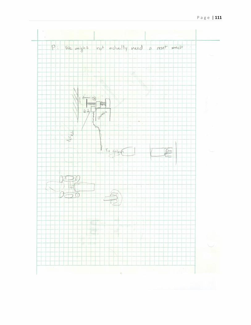
P a g e | 111

P a g e | 112

P a g e | 113

P a g e | 114

P a g e | 115

P a g e | 116

P a g e | 117

P a g e | 118
P a g e | 119

P a g e | 120
Appendix H: Cabin Design Requirements & Specifications
Design Requirements
1.1 Goals and Objectives
1.1.1 The SMSSV project shall provide passengers an efficient transportation in
the Silicon Valley area.
1.1.1-01 POD cars shall provide a safe mode of transportation connecting people throughout Silicon Valley
1.1.1-02 POD cars shall use the strength of the local technology industry base to promote innovation in advanced transportation systems technology. This system is intended to 1) contribute to the advancement of automated transit systems and 2) increase economic development opportunities for San os and surrounding areas.
1.1.1-03 The POD car shall incorporate a design that achieves federal, state, and industry standard levels of performance, safety, accessibility, usability, reliability, and maintainability. This includes passenger protection, crashworthiness, smoke and flammability, and vandal resistance.
1.1.1-04 The POD car shall be designed and implemented in compliance with recognized design criteria for mechanical, electrical, fire safety, and human ergonomic factors
1.1.2 The SMSSV project shall comply with applicable Americans with
Disabilities Act ( ADA) Standards to ensure equal access opportunities and
benefits for individuals with disabilities.
1.1.2-01 The San os Airport AT System vehicle design shall meet the
accessibility and usability requirements of the Americans with
Disabilities Act, Part 37 and 38, for public transit systems.
To fulfill this requirement the SMSSV vehicles be wheelchair-accessible,
provisioned with compliant wheelchair restraints, and provide other protections
for non-disabled passengers. In regards to applicable Federal law, it is acceptable
that only a portion of ATN System vehicles need to be provisioned per ADA
requirements, as long as a comparable level of service is provided to disabled
passengers. This may be accomplished by reserving a small number of ADA-
compliant vehicles at each station or on call from a nearby staging location,
provide complementary paratransit service, or other means.
1.1.2-02 The POD cars shall provide Braille symbol labels for all passenger-operable controls [JHD-This needs to be thought out since typically the main user interface is a touch screen, so ADA compliant vehicles may need a different type of user interface.]
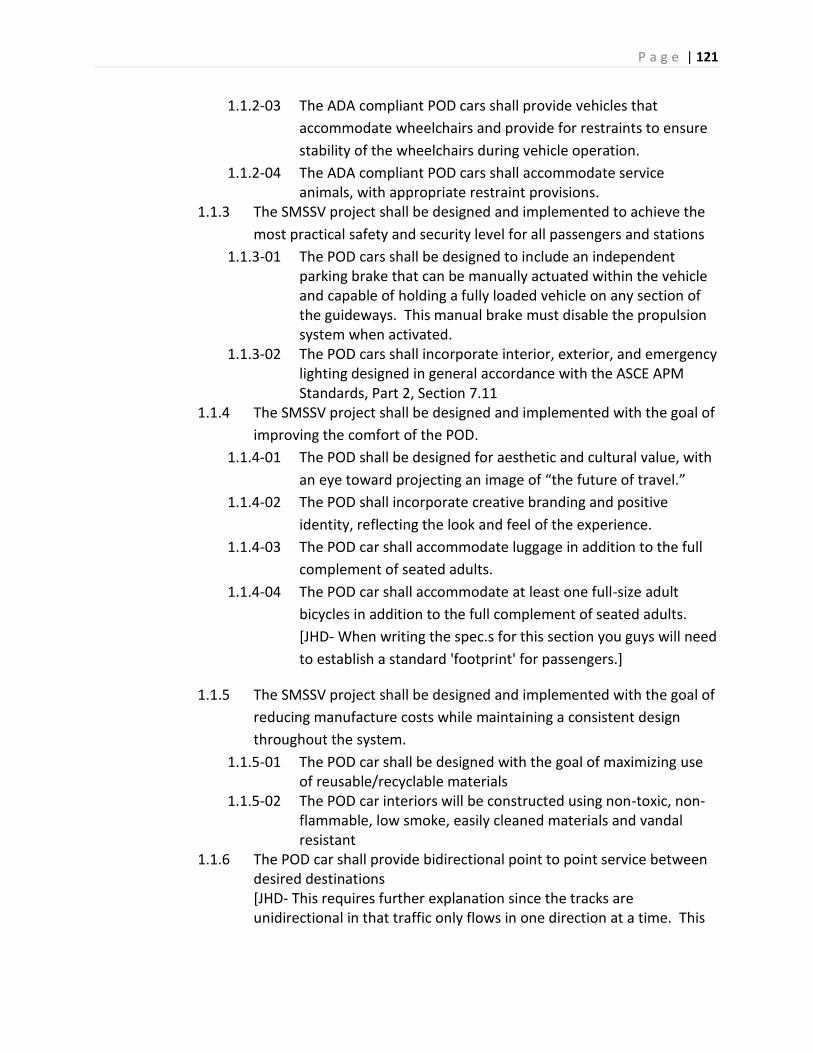
P a g e | 121
1.1.2-03 The ADA compliant POD cars shall provide vehicles that
accommodate wheelchairs and provide for restraints to ensure
stability of the wheelchairs during vehicle operation.
1.1.2-04 The ADA compliant POD cars shall accommodate service animals, with appropriate restraint provisions.
1.1.3 The SMSSV project shall be designed and implemented to achieve the
most practical safety and security level for all passengers and stations
1.1.3-01 The POD cars shall be designed to include an independent parking brake that can be manually actuated within the vehicle and capable of holding a fully loaded vehicle on any section of the guideways. This manual brake must disable the propulsion system when activated.
1.1.3-02 The POD cars shall incorporate interior, exterior, and emergency lighting designed in general accordance with the ASCE APM Standards, Part 2, Section 7.11
1.1.4 The SMSSV project shall be designed and implemented with the goal of
improving the comfort of the POD.
1.1.4-01 The POD shall be designed for aesthetic and cultural value, with
an eye toward projecting an image of “the future of travel.”
1.1.4-02 The POD shall incorporate creative branding and positive
identity, reflecting the look and feel of the experience.
1.1.4-03 The POD car shall accommodate luggage in addition to the full
complement of seated adults.
1.1.4-04 The POD car shall accommodate at least one full-size adult
bicycles in addition to the full complement of seated adults.
[JHD- When writing the spec.s for this section you guys will need
to establish a standard 'footprint' for passengers.]
1.1.5 The SMSSV project shall be designed and implemented with the goal of
reducing manufacture costs while maintaining a consistent design
throughout the system.
1.1.5-01 The POD car shall be designed with the goal of maximizing use of reusable/recyclable materials
1.1.5-02 The POD car interiors will be constructed using non-toxic, non-flammable, low smoke, easily cleaned materials and vandal resistant
1.1.6 The POD car shall provide bidirectional point to point service between desired destinations [JHD- This requires further explanation since the tracks are unidirectional in that traffic only flows in one direction at a time. This

P a g e | 122
means that point to point service MUST be unidirectional and consistent with whatever direction the mainline traffic is moving.]
1.1.7 The POD cars shall be fully automated vehicle with manual override capability
1.1.7-01 The POD car shall provide the capability for passengers to change their desired destination using an in-vehicle data entry interface
1.1.7-02 The POD car shall provide the capability for passengers to immediately request re-routing to a manned emergency station using an in-vehicle data entry interface
1.1.7-03 The ability for passengers to initiate an emergency destination override shall be provided with automatic route selection
1.1.8 The POD car shall be designed to meet specific guideway requirements 1.1.8-01 The POD car bogies shall be designed to operate in guideway
curves with a minimum radius of xx meters 1.1.8-02 The POD car bogies shall be designed to operate on grades up to
+/-xx% 1.1.8-03 The POD car shall be capable of operating with a guideway
superelevation of xx%.
Specifications
1. The cabin is designed based on the following specifications:
1.1 Shall support minimum of 500 pounds (1.4 safety factor applied)
1.2 Shall not exceed maximum total weight of 4000 pounds
1.3 Maximum interior length of 10 feet
1.4 Maximum width of 6 feet
1.5 Maximum height of 8 feet
1.6 Profile shall not have a coefficient of drag (CD) that exceeds 1.05
2. The HVAC system shall meet the following specifications
2.1 Allow for Human Comfort Temperature 70 F to 72 F
2.2 Air not to exceed humidity levels beyond 40-60%
2.3 Use government approved refrigerant
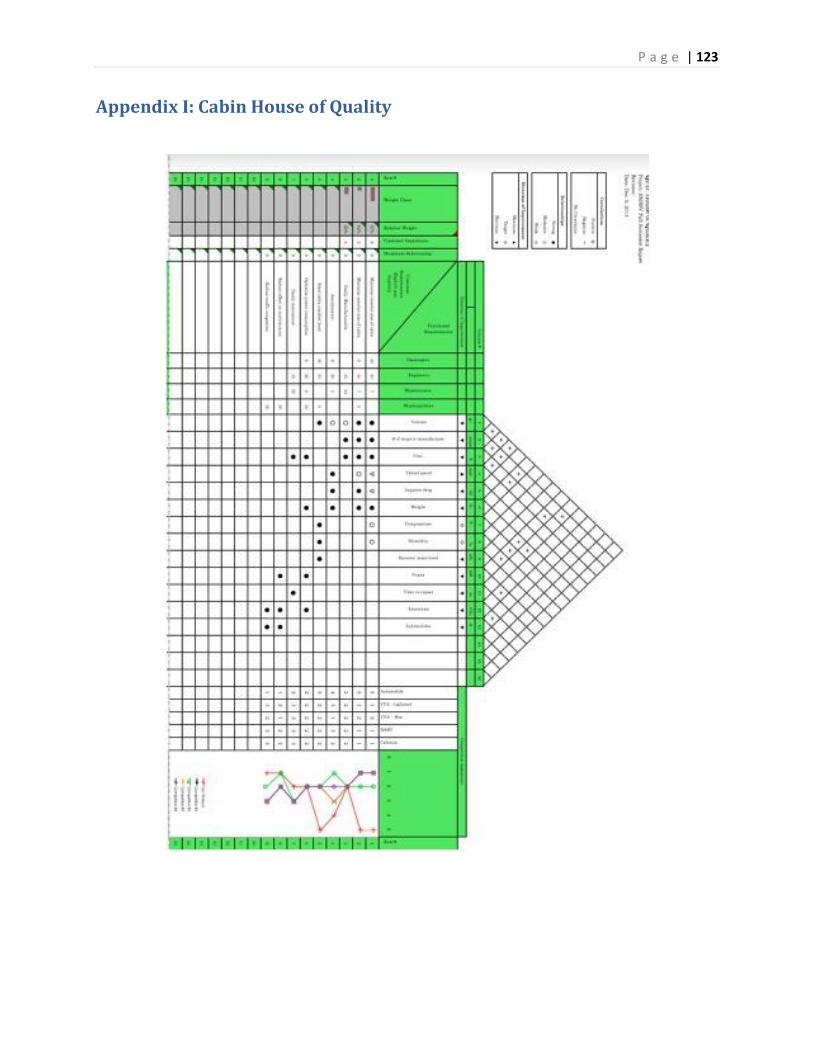
P a g e | 123
Appendix I: Cabin House of Quality

P a g e | 124
Appendix J: Computer Engineering Project Requirements
3.1 Domain and business Requirements
The Superway's control system shall handle all reservations requests, pod scheduling, and emergency
system protocols. Stations and depots shall also be maintained by the control system to allow efficient
loading and unloading of pods while preventing congestion of the system. The pods shall have the
intelligence to prevent local collision and navigate the track without incident, and minimal
communication with the main system. All areas of the system shall have a fail-safe operation in case any
of the critical systems fail. The system shall also allow control system operators to manually adjust the
system when needed.
1. The system shall safely, efficiently, and reliably control the scheduling and routing of pod cars in
fixed track PRT (Personal rapid transit system).
2. The system shall be cost effective to maintain.
3.2 System (or component) function requirements of the Superway
3.2.1 Scheduler
The scheduler monitors the pods current routes, and provides pod with permission to access specific
lengths of the track. It also provides all of the pods with a schedule to get from point A to B.
F1. The scheduler shall communicate with other systems in the following ways:
F1.1. Shall send scheduling info to master controller when a change is made in the schedule.
F1.2. Shall receive scheduling requests from master controller for priority rescheduling and
manual route scheduling.
F1.3. Shall receive scheduling requests from stations.
F1.4. Shall send Scheduling info to stations.
F2. The scheduler shall not allow pod schedules to overlap.
F3. Routes shall be flexible to account for general variations in operating specifications.
F4. Routes shall be changeable.
F5. The scheduler shall schedule the closest unscheduled empty pod to rider.
F6. The scheduler shall schedule a pod from the depot if the predicted wait time > 15min
F7. The scheduler shall schedule a pod that has been empty for > 30min back to a depot.
F8. The scheduler shall schedule an empty pod that is preventing an occupied pod from docking
at a station, back to the depot, taking priority over vii.
F9. The scheduler shall reschedule a pod as follows:
F1.5. Shall reschedule pod with emergency status to the next station.
F1.6. Shall reschedule pods that may interfere with an emergency to stop, slowdown, or
redirect.
F1.7. Shall reschedule pods away from tracks under emergency or maintenance conditions.
F10. The scheduler shall take into account current track and station conditions, closed sections of
track, emergency conditions, safe pod acceleration, and braking times.

P a g e | 125
F11. The scheduler will store usage data for future analytics and load prediction.
3.2.2 Master controller
The Master controller knows the state of the whole system at any given moment and is capable of
manually making changes to the system when needed.
F12. The master controller shall have a manned aspect for monitoring and manual override.
F13. The master controller shall know the current state of all pods, and stations in the system.
F14. The user interface shall:
1. Monitor individual pod statuses: disabled/stopped/unresponsive pods.
2. Detect system malfunctions/anomalies: collisions, guide way obstructions, loss of power
along guide way, and network communication system failures.
3. Allow initiating system startup/shutdown sequences.
4. Allow the manual routing pods.
5. Allow manually designated route segments as operational or temporarily
decommissioned.
6. Allow manually controlling power distribution on a per-zone basis.
7. Allow manually initiating emergency/override protocols.
F15. The master controller shall determine if more or less pods are needed in the system
F16. The master controller shall prevent pods from being routed to closed track.
F17. The master controller shall allow manual overriding of the system by the technician
monitoring.
F18. The master controller shall establish emergency zones restricting pod activity.
F19. The master controller shall communicate with other systems in the following ways:
1. Shall send emergency or manual scheduling requests to the scheduler.
2. Shall receive scheduling info from scheduler.
3. Shall send emergency alerts/directives to stations.
4. Shall receive emergency alerts, and real-time system data from stations.
5. Shall send info to add/remove pods to system, and scheduling info to depots.
6. Shall receive a count of pods in depot from depot.
F20. The master controller handles emergencies in the following ways:
1. If there is an emergency within a pod, the master control:
F20.1.1. shall reroute the emergency pod and interfering pods to allow the emergency pod to
stop at the next station
F20.1.2. Shall alert nearby stations to prevent scheduling to that station.
F20.1.3. Shall prioritize pods with an emergency to dock at the next closest station.
F20.1.4. Shall stop interfering traffic on the track if the pod is immobile.
F20.1.5. Shall designate the track the pod occupies as an emergency zone.
2. If there is an emergency at or with a station the master controller:
F20.2.1. Shall reroute pods directed to that station to the next closest station, using the
scheduler.
P a g e | 126
F20.2.2. Shall designate that station and the tracks leading into stations as an emergency zone.
F20.2.3. If there is a system emergency, such as with the master controller, the master
controller if possible shall alert all stations of emergency.
F21. The master controller shall handle system wide emergencies.
3.2.3 Stations
All pods must load and unload at stations. The goal of the stations is to move people in and out of pods
as quickly as possible while remaining and preventing congestions within the station.
F22. The stations shall communicate with other systems in the following ways:
1. shall receive emergency alerts from master controller.
2. shall send local real-time condition and emergency alerts to master controller.
3. shall send scheduling information, docking information, and emergency alerts to pods.
4. shall receive real-time status updates and emergency alerts from pods.
5. shall send scheduling requests to scheduler.
6. shall receive scheduling requests.
F23. Stations shall control the following processes:
1. the docking process for pods in the stations.
2. preventing congestion in the stations.
3. routing empty pods out of the station to allow occupied pods to dock.
4. allowing users to schedule a pod at the station.
5. not allowing pods to be interrupted while passengers are loading and unloading.
6. closing adjacent tracks leading up to station in case of emergency.
F24. Stations shall monitor and record the following information:
1. real-time local conditions at the stations and of pods within range.
2. how many pods it is in communication with.
3. the status of all pods it communicates with.
4. how many pods are in route to the station.
F25. In the event of an emergency, the station shall send emergency alerts to master controller if
unsafe conditions are detected.
F26. In the event of a pod emergency the station shall:
1. prioritize pods with an emergency to dock.
2. reroute non-emergency pods to next closest station.
F27. In the event of a station emergency/failure the station shall:
1. redirect incoming pods to next safest and closest station using emergency alerts from master
controller.
2. redirect incoming pods to next safest and closest station using emergency alerts from master
controller.
3. not allow scheduling at station.
4. not allow docked pods to leave station.

P a g e | 127
5. not allow incoming pods to dock.
F28. In the event of a system wide emergency/failure the station shall:
1. not allow docked pods to leave station.
2. not allow incoming pods to dock.
3. direct all pods in range to come to a safe stop.
4. assume the system has failed if unable to talk to scheduler or master controller for >10min.
F29. The station shall send all reservations requested through station terminals to the scheduler.
F30. The station servers shall direct pods at stations with multiple loading areas and with active safety
precautions.
3.2.4 Pods
Pods are the vehicles that transport users along the track. The pods must be capable of making safe
decision even if they cannot communicate with the network.
F31. Pods shall communicate with other systems in the following ways:
1. shall receive scheduling information and emergency alerts from stations.
2. shall be in contact with > 1 station at any given moment.
F32. Pods shall control the following onboard processes:
1. maintain a safe distance from adjacent pods.
2. avoid head on collisions with track obstructions.
3. follow the schedule provided by the station.
F33. Pods shall be equipped with object detection sensors capable of detecting other pods and guide
way obstructions.
F34. Pods may be able to detect the presence of other pods and adjust routes accordingly (slipstream
drafting).
F35. Pods shall monitor real time conditions of local system.
F36. In the event of an emergency a pod shall:
1. send emergency alerts to nearby stations if unsafe conditions are detected along the guideway.
2. send to stations emergency alerts, and local real-time conditions of local system.
3. dock at next station in case of on-board emergency.
4. have onboard backup power in case of power failure.
5. dock at next station in case of system power failure.
6. be capable of automatically re-routing to next available station in the event of critical system
malfunction such as power failure.
7. be able to arrive at the station nearest to the destination, should an emergency situation
prevent the pod from completing its route.
F37. Pods shall always be in communications range of a station.
F38. Pods shall only accept commands from stations.

P a g e | 128
F39. Pods shall be able to declare an emergency zone in the immediate area of the guide way such that
the network will prevent any other pods from entering the area.
3.2.5 Depots
When pad are not in use by the system they are stored in the depots. It is also were pod will go for
general maintenance.
F40. Depots shall keep a count of stored pods.
F41. Depots shall communicate with master controller directly.
F42. Depots shall receive all incoming empty pods.
F43. Depots shall add empty pods to the system upon request from master controller.
3.2.6 Start-Up/Shutdown Procedure
F44. The Superway Control System shall have a manual system start-up procedure consisting of phases
in the following order: 1st Central server initialization, 2nd Power interface activation, 3rd Stations
activation, 4th Pod systems activation.
F45. The Superway Control System shall have a manual system shutdown procedure consisting of
deactivating the start-up phases in reverse order.
F46. The Superway pod systems shutdown procedure will allow for all active pods to complete their
routes before returning to designated storage/waiting areas.
3.3 Non-functional Requirements
NF1. The system shall be safe for all users including riders, employees, emergency personnel, people
near and under the guideway system, and maintenance crew.
NF2. The system shall be reliable even in hostile environmental conditions
NF3. The system shall safely and reliably shutdown and startup.
NF4. The system shall handle all situations in the safest manner.
NF5. The system shall manage the number of pods in the system.
NF6. The system shall add and remove pods from circulation during regular operation.
NF7. The system shall manage the flow of pods in and out of stations.
NF8. The system shall manage the scheduling of routes.
NF9. The system shall schedule routes based first on safest, and second on minimum travel time.
NF10. The system shall safely redirect pod currently in transit based on real time conditions.
NF11. The system shall respond safely to emergency situations
NF12. The system shall maintain safe conditions on the tracks at all times.
3.4 Context and interface requirements
C1. The track must be fully implemented
C2. The pod must be able to navigate intersections correctly and consistently.
C3. The pod must have a working bogey
C4. The pod must be securely connected to the guide way
C5. The stations must have a clear entrance and exit
C6. The pod must follow the schedule give to it.

P a g e | 129
C7. The pod must avoid collisions
3.5 Technology and resource requirements
RR1. A database shall be used to store reservation info, pod info, station info, and schedule
information
RR2. Master controller system requirements
RR2.1 Shall run Windows 7
RR2.2 Shall use Wireless G
RR3. Pod control system requirements
RR3.1 Shall run Linux
RR3.2 Shall have 1gb storage
RR3.3 Shall use wireless G
RR4. Station control system requirements
RR4.1 Shall run Linux
RR4.2 Shall have 1gb storage
RR4.3 Shall use wireless G
RR5. Scheduler
RR5.1 Shall have 10gb storage
RR5.2 Shall use wireless G
RR5.3 Shall run a SQL database
RR5.4 Shall run Linux or windows.

P a g e | 130
Appendix K: Controls System Design Requirements and Specifications
Design Requirements
Early on in the semester, each of the Spartan Superway subteams performed an analysis of a feasibility
study conducted by The Aerospace Corporation in regards to implementing an ATN system as part of the
Mineta San José International Airport (SJC) (Paige). Completing this analysis proved a critical step in
establishing the constraints that would guide the design process and controls system development.
Because the 1/12 scale model system serves as the primary means of testing for the Spartan Superway
Controls System, the Controls Team developed its design requirements with two important criteria in
mind: (1) the initial design requirements should focus on requirements capable of visual/physical
representation within a 1/12 scale model, and (2) if a requirement is not capable of being
visually/physically, but is considered system critical, it must be incorporated within the system as early
as possible to prevent future system conflicts. The first criterion mainly deals with features internal to
the pod cabin, such as the HVAC system or the user-interface elements. The second criterion ensures
that the Controls team implements system components dealing with emergency response features at
the beginning of the design process and make them central to the overall system.
1.1 Spartan Superway Control System Design Goals and Objectives
This section of the design requirements outlines the highest level goals and objectives, designated [Tier
0}, which govern all the design requirements that follow. Although most of the requirements within this
section are specific to the Controls team, some of the design requirements greatly depend on
cooperative development between the Controls team and other subteams, such as the Cabin team and
Station team.
[1.1-01] The Superway Control System shall operate in such a manner so as to provide the highest level
of safety and comfort to its ridership. [Tier 0]
[1.1-02] The Superway Control System shall provide robust communications of data, allowing all
network elements (central server, station servers, pod nodes) to send and receive information to any
other network element. [Tier 0]
[1.1-03] The Superway pods shall be able to receive a request from the central server and automatically
pick-up, transport, and drop-off designated passengers without any additional commands from the
central server. [Tier 0]
[1.1-04] The Superway system shall be able to operate with a headway of XX-XX minutes. [TBD] [Tier 0]
[1.1-05] The Superway pods shall be able to utilize all stations and guideways within the system. [Tier 0]
1.2 Spartan Superway Control Systems Sub-Tier Requirements
The following sections divide the bulk of the design requirements into the system areas that they most
directly affect. The sub-tier requirements are divided amongst three major areas: Network Architecture,
Pod Operations, and Safety.

P a g e | 131
1.2.1 Network Architecture
This section deals with the design requirements relating the communications network linking the
network servers with the autonomous pods, as well as providing design requirements for the central
monitoring station.
[1.2.1-01] The Superway Control System communication bandwidths and margins shall operate reliably
under full system operational loads and speeds. [Tier 1] (Paige)
[1.2.1-0X] The Superway Control System communications network shall consist of three elements: [Tier
1]
1. Central server
2. Station servers
3. Pod nodes
1.2.1.1 Central Server
[1.2.1.1-01] The Superway Control System central server shall process all pod reservations. [Tier 1]
[1.2.1.1-02] The Superway Control System central server shall prioritize emergency situations prior to
sending any network commands. [Tier 1]
[1.2.1.1-03] The Superway Control System central server shall automatically schedule pod
routes between any two stations within the network. [Tier 1] (Paige, 2012)
[1.2.1.1-04] The Superway Control System central server shall reserve track sections along pod routes
using a fixed block system. [Tier 2]
[1.2.1.1-05] The Superway Control System central server shall perform re-routing calculations based on
real-time network changes in case of pod delays or network anomalies, failures, or emergencies. [Tier 2]
[1.2.1.1-06] The Superway Control System shall operate such that the number of pods needed to
meet passenger demands and the number of active pods are minimized. [Tier 1]
[1.2.1.1-07] The Superway Control System shall autonomously monitor and manage the operation of all
active pods within the network. [Tier 1] (Paige, 2012)
[1.2.1.1-08] All pods removed from the guideway for maintenance shall be considered inactive. [Tier 2]
1.2.1.1.1 Central Monitoring
[1.2.1.1.1-01] The Superway Control System shall provide a manned central monitoring station with
the capability to monitor, analyze, and control the following system characteristics: [Tier 1]
Overall system operational status
Individual vehicle operational status
Detected system malfunctions/anomalies

P a g e | 132
Disabled/stopped/unresponsive pods
Collisions
Guideway obstructions
Loss of power along guideway
Network communication system failures
Initiating system startup/shutdown sequences
Manually routing pods
Manually designating route segments as operational or temporarily decommissioned
Manually controlling power distribution on a per-zone basis
Manually initiating emergency protocols
[1.2.1.1.1-02] The Superway Control System central monitoring station shall provide a user interface to
the communications network central server. [Tier 2]
1.2.1.2 Station Server
[1.2.1.2-01] The Superway Control System station servers shall send all reservations requested through
station terminals to the central server. [Tier 1]
[1.2.1.2-02] The Superway Control System station servers shall direct pods at stations with multiple
loading areas or with active safety precautions. [Tier 1]
[1.2.1.2-03] The Superway Control System station servers shall be able to monitor and relay pod
statuses in the event a pod cannot communicate with the central server. [Tier 1]
1.2.1.3 Pod Nodes
[1.2.1.3-01] The Superway Control System pods shall be able to detect the presence of other pods and
adjust routes accordingly (slipstream drafting). [Tier 1]
1.2.2 Pod Operations
This section outlines the design requirements critical for producing fully-autonomous pods capable of
carrying out all the tasks that the network assigns to it without further intervention.
[1.2.2-01] The Superway pods shall ensure comfortable and safe operations with no collisions. [Tier 1]
[1.2.2-02] The Superway pods shall be equipped with object detection sensors capable of detecting
other pods and guideway obstructions. [Tier 2]
[1.2.2-03] The Superway pods shall maintain a safe distance away from any pod or
obstruction on the guideway. [Tier 2]
[1.2.2-04] the safe distance shall be calculated in real-time based on the pod's speed and braking
capabilities, and the detected object's speed. [Tier 3]
[1.2.2-05] The Superway pods shall be able to determine that a previously moving vehicle has come to a
complete stop. [Tier 4]

P a g e | 133
[1.2.2-06] The Superway pods shall only accept commands from the central server and station servers.
[Tier 1]
[1.2.2-07] Commands from the central monitoring station operator shall be interpreted as commands
from the central server. [Tier 2]
[1.2.2-08] The Superway pods standard acceleration and deceleration shall be based on comfort of the
passengers while the pod is occupied. [Tier 1]
[1.2.2-09] The acceleration rate shall be determined to limit the jerk rate to a maximum of 0.25 g. [Tier
2] (American Society of Civil Engineers)
[1.2.2-10] The Superway pods shall be capable of emergency breaking up to 0.6g [Tier 2] (American
Society of Civil Engineers)
[1.2.2-11] The Superway pod speed shall be maintained within maximum speed limits allowed by real-
time guideway conditions. [Tier 1]
[1.2.2-12] The Superway pods shall not accelerate while the breaks are engaged. [Tier 1]
[1.2.2-13] The Superway pods shall be able to automatically decelerate prior to entering turns. [Tier 1]
(Paige, 2012)
[1.2.2-14] The Superway pods shall be able to determine their current location by reading markers
placed along the guideway with an optical sensor. [Tier 1]
[1.2.2-15] The Superway pods shall be able to detect unintentional motion and apply emergency braking
to counteract it. [Tier 1] (Paige)
[1.2.2-16] The Superway pods shall be able to declare an emergency zone in the immediate area of the
guideway such that the network will prevent any other pods from entering the area. [Tier 1] (Paige)
1.2.3 Safety
The design requirements outlined in this section critical to the safety of the overall system and its riders
and are meant to ensure a reliable system.
[1.2.3-01] The Superway pods shall communicate any accidents or emergencies to the central server.
[Tier 1] ASCE APM Standard 21-05 requires two-way audio communication between the Central Control
and all passenger stations. (ASCE APM)
[1.2.3-02] The Superway pods shall be able to arrive at the station nearest to the destination should an
emergency situation prevent the pod from completing its route. [Tier 1]

P a g e | 134
1.2.3.1 System Redundancy
[1.2.3.1-01] The Superway pods shall be capable of automatically rerouting to next available station in
the event of critical system malfunction. [Tier 1]
[1.2.3.1-02] The Superway pod's guideway switching mechanism shall not be capable of producing
an indeterminate state. [Tier 1] ASCE APM Section 5.1.14 requires that switching mechanism be
prevented from automatically or manually unlock until the cab has cleared the section
[1.2.3.1-03] The Superway pods will be capable of switching to an on-board, auxiliary power source in
the event of a vehicle power interface malfunction or a system-wide power outage. [Tier 1]
[1.2.3.1-04]The Superway pod auxiliary power source will provide enough power to get the pod to the
next available station if triggered. [Tier 2]
[1.2.3.1-05]The Superway pods will be able to automatically detect auxiliary power
discharge malfunctions. [Tier 2]
1.2.3.2 Start-Up/Shutdown Procedure
[1.2.3.2-01] The Superway Control System shall have a manual system start-up procedure consisting
of phases in the following order: [Tier 1]
Central server initialization
Power interface activation
Pod systems activation
[1.2.3.2-02] The Superway Control System shall have a manual system shutdown procedure consisting
of deactivating the start-up phases in reverse order. [Tier 1]
[1.2.3.2-03] The Superway pod systems shutdown procedure will allow for all active pods to complete
their routes before returning to designated storage/waiting areas. [Tier 2]
[1.2.3.2-04] The Superway Control System shall have manually-initiated emergency shutdown
protocols for each phase of the shutdown procedure accessible from the central monitoring station.
[Tier 1]
Design Specifications
Because the Controls team’s design process consists mostly of software development for existing
hardware components, producing design specifications required a significantly different design process
relative to the other subteams. The Cabin, Bogie, Guideway, and Station teams need to develop design
specifications for designs that will likely only be fabricated once during this year’s design iteration, due
to the expense and time required to fabricate it. The Controls team has the advantage being able to test
software iterations as frequently as they can develop them. For this reason, the Controls team design
process follows what is known as an Agile Development Cycle for the phases of testing, debugging, and
ultimately finalizing a design to deliver.

P a g e | 135
Since the design process consists primarily of developing software to manipulate components of the
overall system, the majority of the design specifications deal with variables that the Controls System
must monitor and adjust as the situation demands. For determining these variables, the Controls team
consulted the Automated People Mover Standards (APM) published by the American Society of Civil
Engineers (ASCE) (American Society of Civil Engineers). The design specifications for the current
development stage are detailed below, with accompanying data specifications in Error! Reference
source not found..
The acceleration and deceleration rate will never exceed 0.25g.
The Superway pods shall be capable of emergency braking up to 0.6g.
The Superway Pods shall begin decelerating when the object in front of the pod is D1
centimeters away.
The Superway Pods shall apply emergency brakes and decelerate at 0.6g when the object in
front of the pod is D2 centimeters away.
Table 8. Full and 1/12 Scale Object Detection Specification Substitutions
Letter Specification 1/12 Scale Full Scale
D1 (cm) 25 8500
D2 (cm) 15 2800
The equations performed to get the distance values did not take into account wind resistance. The way
the measurements were calculated by the controls team was to first assume that the speed of the pod is
96.6km/h at time 0 and that the starting distance is zero at time zero. Next, take the deceleration rate
and integrate it by time then apply the initial conditions. Shown below are the equations that were
formed to find D1.
( )
( )
( )
Please note that the equations shown above are in centimeters. The two hundred forty five cm/s2was
calculated by taking Earth’s gravity constant and multiplying it by 0.25. The rest of the values were
calculated by taking the integral and adding in the constants. The D2 value is a rough estimate of two
thirds of the D1 value. The reasoning for this is because the pod before coming into this stage has
already been decelerating constantly and only after hitting D2 will it fully apply the brakes to make the
pod come to a full stop.
In addition to the design specifications dictated by the APM Standards, the Controls team
established the following design specifications for development of the 1/12 scale model:
The Controls System subsystems (i.e. speed control, object detection, guideway switching
control, and position tracking) will each be controlled by its own microcontroller.

P a g e | 136
The microcontroller used for each subsystem will be Arduino-compatible. The specific board
used for a particular subsystem will be scaled based on the number of pins required to minimize
space and power consumption.
The test pods will communicate to the network through a Wi-Fi network.
A BeagleBone Black will provide each pod with communication to the network.
The BeagleBone Black will also coordinate each subsystem microcontroller using the Serial
Peripheral Interface (SPI) bus communication protocol.

P a g e | 137
Appendix L: Guideway Design Requirements and Specifications
Design Requirements
1. Visual Aspects 1.1. The guideway shall minimally impact the visual appeal of the locations it is constructed in
2. Design/load guidelines 2.1. The guideway will be capable of being subjected to bending and thermal expansion without
compromising the functionality of the system, or the comfort of passengers 2.2. The guideway will be able to support the applied loads (bogie, multiple cars, power system) 2.3. The guideway shall not produce unacceptable decibel level 2.4. The guideway will be able to travel on inclines
3. Maintenance Aspects 3.1. The guideway will have adequate protection from biological debris or appropriate cleaning
methodologies 3.2. The guideway shall be designed for a long lifespan, under normal loading conditions 3.3. The guideway will have adequate access for maintenance
4. Safety Precautions 4.1. The guideway shall be constructed in such a way that pod impact from opposite direction travel
cannot occur 4.2. The supports shall withstand impact from ground traffic without catastrophic failure
Design Specifications
1. The guideway will not exceed an exterior diameter of two meters. 2. The guideway will be able to withstand temperature changes from 120 F (49 C) to -20 F (-29 C)
without structural failure (National Oceanic and Atmospheric Administration) 3. The guideway will support the combined mass of the system (cars, bogies, solar system) of
15000 kg between each set of supports with a safety factor greater than 2.0 [1] 4. The guideway posts will support the combined mass of the system (guideway, cars, bogies, solar
system) of 18000 kg between each set of posts with a safety factor greater than 2.0 [1] 5. The guideway will not produce decibel levels of more than 50 dBA, the standard noise level for
inner city environments during the day (City of San Jose) 6. The guideway will be capable of withstanding seismic vibrations of a 7.0 magnitude without
catastrophic failure (Homefacts) 7. The guideway will be able to traverse an incline of ten degrees 8. The guideway will have a mechanism that will remove/prevent 95% of biological material from
accumulating 9. The guideway will be designed to last 50 years under maximum planned loading. 10. The guideway will have one maintenance access point for every support structure. 11. The guideway posts will be capable of withstanding an impact from a 6000 pound vehicle
traveling at 20 mph over the posted speed limit on the roadway that the guideway support is adjacent to
12. The guideway will adhere 100% (or greater where applicable) to the parameters of government building codes
13. The guideway will have location identification markers every ten meters for the pods to autonomously communicate their current location [2]
14. The guideway will have a maximum interior boundary of one meter by one meter. 15. The guideway will be designed to have a minimum turning radius of 50 feet (City of San Jose).

P a g e | 138
16. The guideway will provide a conduit for power to flow from the solar panels to the bogie and/or cabin.
17. The guideway will be designed to allow the drainage of 100% of water from rainfall. 18. The Guideway will have electrical grounds at every support structure that will discharge high
voltage impulses of energy or high buildup of electrical charge, such as from a lightning strike.

P a g e | 139
Appendix M: Guideway House of Quality

P a g e | 140
Appendix N: HCD Survey 1 Data and Results
What is your Age?
Age Totals
18 1
19 4
20 6
21 5
22 4
23 8
24 4
25 3
26 2
27 0
28 0
29 5
30 0
31 1
32 1
33 0
34 0
35 0
36 0
37 0
38 0
39 0
40 0
41 0
42 1
43 1
44 0
45 1
46 0
47 0
48 0
49 0
50 2
51 0

P a g e | 141
52 0
53 0
54 0
55 0
56 0
57 0
58 1
59 0
60 0
61 0
62 0
63 1
64 0
65 0
72 1
What is your gender?
Male Female
34 28
Teenagers 9%
20's 71%
30's 4%
40's 6%
50's 6%
60's 2%
70's 2%

P a g e | 142
What is your occupation?
Occupation Total
student 29
self employed 1
attorney 1
accountant 1
IT 1
manager 2
teacher 3
engineer 5
graphic design 1
lab tech 1
retail 1
clerk 3
electrician 1
nurse 1
office manager 1
insurance claim adjuster 1
retired 1
Male 55%
Female 45%

P a g e | 143
Do you own a car/home?
CAR HOUSE
YES NO YES NO
37 19 10 46
student 54%
self employed 2%
attorney 2%
accountant 2% IT
2%
manager 4%
teacher 6%
engineer 9%
graphic design
2%
lab tech 2%
retail 2%
clerk 6%
electrician 2%
nurse 2%
office manager
2%
insurance claim adjuster
2%
retired 2%
YES 66%
NO 34%
Own a Car
YES 18%
NO 82%
Own a Home

P a g e | 144
How often do you take public transportation?
everyday 22
twice per week 8
rarely 16
once a week 2
3 times week 1
no answer 1
What form of public transportation do you take?
BUS 20
LIGHTRAIL 22
TRAIN 18
BART 13
TAXI 1
NO ANSWER 3
everyday 44%
twice per week 16%
rarely 32%
once a week
4%
3 times week
2%
no answer
2%

P a g e | 145
How many people do you travel with?
no answer 0 1 2 3
2 52 8 7 1
BUS 26%
LIGHTRAIL
29%
TRAIN 23%
BART 17%
TAXI 1%
NO ANSWER
4%
no answer
3%
alone 74%
one 12%
two 10%
three 1%

P a g e | 146
Why do you take public transportation?
enviorment 4
save money 15
safety 1
don’t have to drive 7
worry about parking 7
no answer 4
time to myself 1
can do work (or hw) 5
traffic 7
reliability 6
save time 1
read 2
surf internet 1
road rage 1
phone 1
schedule 4
convient 5
enviorment
6%
save money
21% safety
1%
don’t have to
drive 10%
worry about
parking 10%
no answer 6%
time to myself
1%
can do work (or
hw) 7%
traffic 10%
reliability 8%
save time 1%
read 3%
surf internet
1%
road rage 1%
phone 1%
schedule 6%
convient 7%

P a g e | 147
Worst part about taking public transit?
Takes too long 17
Not clean 5
not conveient 4
not comfortable 1
overcrowed 13
unavailable at times 3
wifi not always working properly 1
too many stops and/or transfers 4
no trash cans, so people leave gargabe 1
no direct trains 1
cost 3
unsafe 1
unrelaible 2
wait time / delays 8
noisy 1

P a g e | 148
What would make riding public transit easier for you?
express routes 6
direct bus/train 6
make more convient stops 7
have more buses/trains running 11
more reliability 6
bathrooms 1
mobile app to add value to passes 1
personell to ensure cleanliness 1
Wifi 1
lower costs 1
app that shows real time schedules 1
decreasing avg wait time 2
safety 1
use rubber wheels to reduce noise 1
larger capacity trains/buses 1
bike racks 1
Takes too long 26%
Not clean 8%
not conveient
6%
not comfortable 1%
overcrowed 20%
unavailable at times 5%
wifi not always working properly
1%
too many stops and/or transfers
6%
no trash cans, so people leave
gargabe 1%
no direct trains
2%
cost 5%
unsafe 2%
unrelaible 3% wait time / delays
12%
noisy 2%

P a g e | 149
express routes 13%
direct bus/train 13%
make more convient stops 15%
have more buses/trains running
23%
more reliability 13%
bathrooms 2%
mobile app to add value to passes
2%
personell to ensure
cleanliness 2%
Wifi 2%
lower costs 2%
app that shows real time schedules
2%
decreasing avg wait time
4% safety 2%
use rubber wheels to reduce noise
2%
larger capacity trains/buses
2%
bike racks 2%

P a g e | 150
Preferred crowd size while traveling?
Large Crowd 13
On my own 18
no preferance 19
Large Crowd
26%
On my own 36%
no preferanc
e 38%

P a g e | 151
What do you like to do while riding public transportation?
read 15
music 22
enjoy scenery 7
work / study 9
phone / laptop 12
sleep 2
nothing 1
think 2
talk 2
people watch 1
relax 1
draw 1
read 20%
music 29%
enjoy scenery 10%
work / study 12%
phone / laptop
16%
sleep 3%
nothing 1% think
3%
talk 3%
people watch 1% relax 1%
draw 1%

P a g e | 152
How do you get to the station?
walk 30
drive 10
drop off 9
bus 3
bike 9
lightrail 1
walk 48%
drive 16%
drop off 14%
bus 5%
bike 15%
lightrail 2%

P a g e | 153
Appendix O: HCD Survey 2 Data and Results

P a g e | 154

P a g e | 155

P a g e | 156

P a g e | 157

P a g e | 158
0 3% 5% 5% 27% 23% 18% 20% 0.00%
5.00%
10.00%
15.00%
20.00%
25.00%
30.00%
I would switch to public transit if it were more reliable.
2% 2% 2% 9% 16% 31% 39% 0.00%5.00%
10.00%15.00%20.00%25.00%30.00%35.00%40.00%45.00%
I would take public transit to avoid traffic congestion.

P a g e | 159
1% 1% 1% 8% 11% 26% 53% 0.00%
10.00%
20.00%
30.00%
40.00%
50.00%
60.00%
I would switch to public transit if it was as convenient and fast as my car.
13% 15% 9% 18% 17% 17% 13% 0.00%2.00%4.00%6.00%8.00%
10.00%12.00%14.00%16.00%18.00%20.00%
I choose public transit over my car because of the free time I have while riding it.
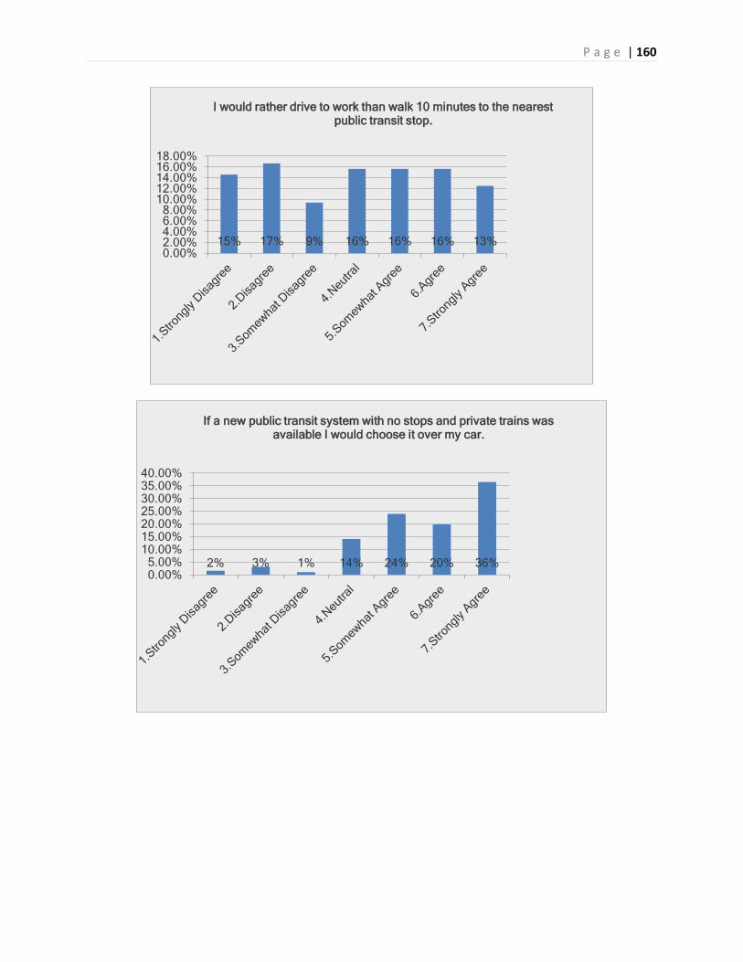
P a g e | 160
15% 17% 9% 16% 16% 16% 13% 0.00%2.00%4.00%6.00%8.00%
10.00%12.00%14.00%16.00%18.00%
I would rather drive to work than walk 10 minutes to the nearest public transit stop.
2% 3% 1% 14% 24% 20% 36% 0.00%5.00%
10.00%15.00%20.00%25.00%30.00%35.00%40.00%
If a new public transit system with no stops and private trains was available I would choose it over my car.

P a g e | 161
2% 3% 5% 30% 20% 19% 21% 0.00%5.00%
10.00%15.00%20.00%25.00%30.00%35.00%
Solar Power is the future of public transportation.
7% 13% 16% 34% 15% 11% 5% 0.00%5.00%
10.00%15.00%20.00%25.00%30.00%35.00%40.00%
I choose public transit instead of my car because I care about the environment.

P a g e | 162
22% 21% 18% 16% 13% 6% 4% 0.00%
5.00%
10.00%
15.00%
20.00%
25.00%
Even if public transit was as convenient as my car, I would still drive instead.
2% 1% 3% 12% 21% 26% 35% 0.00%5.00%
10.00%15.00%20.00%25.00%30.00%35.00%40.00%
I would take public transit to avoid traffic congestion.

P a g e | 163
Appendix P: Solar Design Requirements and Specifications
Solar Power System Design Specifications
1. The overall system shall operate safely and normally under the following conditions:
[1.1] Maximum operating temperature of 133 oF (1.2 factor of safety applied)
[1.2] Minimum operating temperature of -20 oF (1.2 Factor of safety applied)
[1.3] Maximum gusts of 69 mph (1.2 Factor of safety applied)
[1.4] Maximum sustained winds of 9.96 mph (1.2 Factor of Safety applied)
[1.5] Maximum earthquake 9.48 on the Richter scale (1.2 Factor of safety applied)
[1.6] Maximum of 7 days of rain
[1.7] Maximum of 2 days of snow
2. The overall system design will allow for the following:
[2.1] Local electrical grid connection at 208, 240, 277, 400, and 480 VAC
[2.2] Local electrical grid frequency synchronization (typically 60 Hz)
[2.3] Handle maximum produced power of 13kW
[2.4] Maximum Vertical rotation of 360o
[2.5] Maximum Horizontal rotation of 180o
[2.6] Maximum number of panels (typically 8 panels)
[2.7] Support a maximum combined weight of 537.6 lbs (67.2 lbs x 8 panels) (1.2 factor of safety
applied)
[2.8] Support both of grid and grid-tie inverters up 15kW
3. The overall system will adhere to the following standards:
[3.1] ISO 9001:2008
The ISO 9000 family addresses various aspects of quality management and contains some of
ISO’s best known standards. The standards provide guidance and tools for companies and
organizations who want to ensure that their products and services consistently meet customer’s
requirements, and that quality is consistently improved.
[3.2] ISO 14001:2004
The ISO 14000 family addresses various aspects of environmental management. It provides
practical tools for companies and organizations looking to identify and control their
environmental impact and constantly improve their environmental performance. ISO 14001:2004
and ISO 14004:2004 focus on environmental management systems. The other standards in the
family focus on specific environmental aspects such as life cycle analysis, communication and
auditing.
Solar Design Requirements
The Superway Solar Power System design requirements are based weeks of research, interviews with
solar engineering professionals, team brainstorming sessions. Per accepted systems engineering

P a g e | 164
practice, each design requirement is expressed as a single, discrete statement describing a specific need,
function, performance level, quality, or constraint relevant to the system.
1.1 Superway Solar Power System Design Goals and Objectives
The top-level goals and objectives of the Solar Power System are specified in this requirements outline
as [Tier 0] requirements. These requirements address the basic solar power generation functionality of
the system along with additional goals of interest to the Superway team. All lower-level requirements
for the automated transportation network (ATN) system implementation are ultimately derived from
these top-level goals and objectives.
The Superway Solar Power System shall be designed and implemented with the goal of improving
energy generation, energy production efficiency, reliability, and manufacturability.
[1.1-01] The Superway Solar Power System should be designed to provide a reliable and environmentally
sustainable supplemental energy supply for the Superway ATN, adhering to local and state standards
governing public transportation energy supply systems. [Tier 0]
[1.1-02] The Superway Solar Power System shall be designed and implemented with the goal of
increasing the use of renewable energy sources in public transit services. [Tier 0]
[1.1-03] The Superway Solar Power System shall be designed and implemented with the goal of
improving the convenience of access to a renewable energy source for public transit systems. [Tier 0]
[1.1-04] The Superway Solar Power System shall be designed and implemented with the goal of
developing a system that minimizes the operational costs of the services relative to any currently
deployed renewable energy source used in public transit. [Tier 0]
[1.1-05] The Superway Solar Power System shall be designed and implemented with the goal of
providing an environmentally sustainable energy source for the entire Superway ATN that minimizes
environmental impacts. [Tier 0]
[1.1-06] The Superway Solar Power System shall provide a foundation for the continued development
solar power energy supply systems for use as a supplemental source of energy for AT ’s. [Tier 0]
1.2 Superway Solar Power System Sub-Tier Requirements
This section presents the requirements for the Superway Solar Power System.
1.2.1 Superway ATN Energy Needs
In this section, the energy demand of the Superway ATN are characterized in terms of the estimated
average kW and peak kW per operating period, and overall daily kWh per mile of track for the entire
system. The estimated energy demand of the ATN will be compared against the energy generation
capacity of solar panels to determine the size of a solar network with sufficient capacity to meet the
projected demand. The reliability of the solar power network will be compared against the reliability of
power sources required for an ATN.

P a g e | 165
1.2.2 Superway Solar Power System Support Structure
[1.2.2-01] The Superway Solar Power System shall have a support structure capable of supporting the
static and dynamic loads of the solar panels without failing. [Tier 1]
[1.2.2-02] The Superway Solar Power System shall support structure should be designed with materials
that minimize weight without compromising the structural integrity under design static and dynamic
load conditions. [Tier 1]
[1.2.2-03] The Superway Solar Power System shall have a support structure resistant to environmental
conditions. [Tier 1]
[1.2.2-04] The Superway Solar Power System support structure should be designed to withstand all
estimated wind loads. [Tier 1]
[1.2.2-05] The Superway Solar Power System support structure should be designed to facilitate
maintenance and repair. [Tier 1]
[1.2.2-06] The Superway Solar Power System support structure should be designed for ease of
manufacturing and onsite installation. [Tier 1]
[1.2.2-07] The Superway Solar Power System support structure should be designed for easy assembly
and integration into the overall Superway transportation guide way structure. [Tier 1]
[1.2.2-08] The Superway Solar Power System support structure should be designed such that it does not
interfere with the dynamic envelope of the pods and guide way structure elements. [Tier 2]
1.2.3 Superway Solar Power System Tracking Mechanism
[1.2.3-01] The Superway Solar Power System Tracking Mechanism shall deliver the greatest power
density per tract or acre of land. [Tier 1]
[1.2.3-02] The Superway Solar Power System Tracking Mechanism should be designed to minimize
footprint. [Tier 1]
[1.2.3-03] The Superway Solar Power System Tracking Mechanism shall use a single axis tracking system
to follow the sun from sunrise to sunset. [Tier 1]
1.2.4 Superway Solar Power System Motorized Controls
[1.2.4-01] The Superway Solar Power System Motorized Controls shall be able to quickly and efficiently
move the panels and enclosure structure to the position commanded by the solar tracker. [Tier 1]
[1.2.4-02] The Superway Solar Power System motorized controls shall use a single axis stepper motor
that will drive the panels bi-directionally. [Tier 1]
[1.2.4-03] The Superway Solar Power System motorized controls will rotate clockwise and counter-
clockwise easily and hold high torques. [Tier 1]

P a g e | 166
[1.2.4-04] The Superway Solar Power System shall incorporate a mechanism to manually operate the
motors. [Tier 1]
[1.2.4-05] The Superway Solar Power System shall have a fail-safe mechanism remove power from the
motors in the event of a fault. [Tier 1]
[1.2.4-06] The Superway Solar Power System will allow for remote shutdown of any motor in case of a
runaway condition. [Tier 1]
[1.2.4-07] The Superway Solar Power System shall include a method for testing the motorized controls
system. [Tier 1]
1.2.5 Superway Solar Power System Power Transfer Mechanism
[1.2.5-01] The Superway Solar Power System should be designed with acceptable power quality such
that it can be connected to the local electrical grid. [Tier1]
[1.2.5-02] The Superway Solar Power System shall provide an efficient way of converting the direct
current (DC) energy, generated by the photovoltaic (PV) modules, to alternating current (AC). [Tier 1]
[1.2.5-03] The Superway Solar Power System shall include a redundant fail safe mechanism to guard
against PV module DC overload. [Tier 1]
[1.2.5-04] The Superway Solar Power System shall provide a method to negate the islanding effects
caused by grid connected PV systems. [Tier 1]
[1.2.5-05] The Superway Solar Power System shall allow for maximum hours of operating while
minimizing the overall cost of the system. [Tier 1]
[1.2.5-06] The Superway Solar Power System shall include a method for data monitoring. [Tier 1]
[1.2.5-07] The Superway Solar Power System requires the data monitoring system to be accessed locally
and over the web. [Tier 2]
[1.2.5-08] The Superway Solar Power System shall incorporate a design that provides easy operating and
maintenance access. [Tier 1]
[1.2.5-09] The Superway Solar Power System should be design to minimize overall system mass. [Tier 1]
Research of Competition
Sun Power
X-Series Solar Panels
sp_X21_335_345_ds_en_ltr_504828A_040513.pdf
Corrosion-resistant frames are guaranteed for 25 years (that’s longer than most roofs)
Tempered front glass maximizes impact resistance

P a g e | 167
E-Series Solar Panels
sp_E20_327_320_ds_en_ltr_MC4Comp_504860B.pdf
AC-Series Solar Panels
Satellite.pdf
Easy to install around obstructions, shaded areas and on complex rooftops
Simplifies system design, with panel level DC to AC power conversion
Improves your energy harvest, with power optimization at the panel level
Enables detailed energy monitoring of each individual panel
Backed by the SunPower industry-leading 25-year warranty, to guarantee your investment
Inverters
sp_X21_335_345_ds_en_ltr_504828A_040513.pdf
Corrosion-resistant frames are guaranteed for 25 years (that’s longer than most roofs)
Tempered fron
Tracking systems
T20 Tracking System
sp_t20tracker_en_ltr_w_ds.pdf
System Monitoring
Continuously monitored to ensure that it produces 100%
If system does not produce the power expected, it will auto notify.
Sunny Boy
Grid-tied inverters
3000TL-US/ 4000TL-US/ 5000TL-US
o Topology: transformerless
o Max. DC-voltage: 600 V
Max. AC-power: 3000 W / 4000 W / 5000 W
o 240-US
o Module-level, real-time monitoring
o Superior thermal design concept
o Extensive lab and field testing
3000-US/ 3800-US/ 4000-US
o Topology: LF transformer
o Max. DC-voltage: 500 V / 600 V / 600 V
o Max. AC-power: 3000 W / 3800 W / 4000 W

P a g e | 168
5000-US/ 6000-US/ 7000-US/ 8000-US
o Topology: LF transformer
o Max. DC-voltage: 600 V
o Max. AC-power: 5000 W / 6000 W / 7000 W / 8000 W
6000-US/ 7000TL-US/ 8000TL-US/ 9000TL-US/ 10000TL-US/ 11000TL-US
o Topology: transformerless H5
o Max. DC-voltage: 600 V
o Max. AC-power: 6000 W / 7000 W / 8000 W / 9000 W / 10000 W / 11000 W
2000HF-US/ 2500HF-US/ 3000HF-US
o Topology: HF transformer
o Max. DC-voltage: 600 V
o Max. AC-power: 2000 W / 2500 W / 3000 W
Sunny Central Combiner Boxes
o Simplify wiring for added convenience and safety
Combi-switch
o Combination DC disconnect and PV array combiner box
Light Manufacturing Systems
o Heliostats
o Tracking Systems
o Power Transfer

P a g e | 169
Appendix Q: Solar House of Quality

P a g e | 170
Appendix R: Station Design Requirements and Specifications
Design Requirements
1. Visual Aspects 1.1. The station will not be too large as to create an unpleasant view 1.2. The station will encroach on a minimum number of existing establishments
2. Construction Requirements
2.1. The station will meet or exceed the appropriate safety precautions as stipulated by local, state, and federal laws.
2.2. The station design shall meet or exceed local, state, federal, and any other applicable building codes
2.3. The station will be located in areas that minimize disruptions of the current operations of that area
2.4. The station will be capable of withstanding large seismic vibration 2.5. The station will have protection from vehicles hitting it
3. Design Requirements
3.1. The station shall not produce unacceptable decibel levels 3.2. The station will have specified loading and unloading zones 3.3. The station design should be modular, to facilitate the construction of stations with various
capacities 3.4. The station will load and unload passengers at the level of the rails 3.5. The station will be off-line, to allow traffic to flow 3.6. The station will be capable managing the traffic level for the area it is located.
4. Compatibility Requirements
4.1. The station will have on site servers, capable of communication with the central controls system
4.2. The station will provide assistance with the identification of the destination of pods 4.3. The station will use energy generated from solar panel on guideway for power, when power is
available. Otherwise, it will draw power from the grid.
5. Accessibility Requirements 5.1. The station shall conform to the Americans with Disabilities Act 5.2. The station shall be easy to navigate for non-English speaking users 5.3. The station will provide a safe, comfortable, and efficient experience for disabled riders and
non-disabled riders
Design Specifications
1. The Station will have geometry limits of three stories tall, three pod lengths wide and 30 feet deep 2. The Station will displace two or fewer existing establishments 3. The Station will have 100% or greater amount of each individual human health and safety precaution
installed. 4. The Station will adhere 100% (or greater where applicable) to the parameters of government building
codes 5. The Station, when constructed, will effect two or less businesses or residences in a negative manner

P a g e | 171
6. The Station will be capable of withstanding seismic vibrations of a 5.0 magnitude without structural damage (Homefacts).
7. The Station will be capable of withstanding an impact from a 6000-pound vehicle traveling at 20 mph over the posted speed limit on the roadway that the station is adjacent to
8. The Station will not produce decibel levels of more than 50 dBA, the standard noise level for inner city environments during the day (City of San Jose)
9. The Station will have at minimum two loading-unloading zones or one loading zone and one unloading zone
10. The Station will be able to have additional sections constructed to accommodate increased travel levels in the future for a cost of 50% or less than the cost of building from the ground up
11. The Station will have sufficient height to ensure passenger loading occurs at the guideway level, i.e., the guideway will not descend to a ground level station.
12. The Station will be set back a distance from the main guideway to ensure a minimum three foot gap between pods passing the station and pods being loaded/unloaded at the station
13. The Station will provide methods for passengers such that the average wait time for a pod does not exceed five minutes under normal operating conditions
14. The Station will have one on site server that can communicate to the control center 15. The Station will have a minimum of two interior and two exterior displays, showing the arrival times
for pods 16. The Station will be energy efficient such that a minimum of 50% on average (assuming a clear sky
during the day) of electricity consumed will be supplied from the solar panels 17. The Station will conform 100% (or greater where applicable) to the American's with Disabilities Act 18. The Station will provide four major language interpretations for understanding, use, and
functionality at 100% of the locations in which the same instructions are provided in English (Excluding some emergency systems, see specification 19)
19. The Station will provide visual cues and pictures at 100% of instructional and safety locations to assist those not literate or incapable of reading English to understand the use and function of the station as well as the use and function of the human health and safety systems.

P a g e | 172
Appendix S: Station House of Quality