Embed Size (px)
Citation preview

SUPERPAVE VOLUMETRIC MIXTURE
DESIGN AND ANALYSIS
HANDBOOK

TABLE OF CONTENTS
Volume Topic
I Mixture Design & Analysis
II Laboratory Manual (includes data sheets)
III Laboratory Study Manual (mailed directly to the participants)
IV KDOT Standard Test Methods
V KDOT Special Provisions

SUPERPAVE VOLUMETRIC MIXTURE DESIGN AND ANALYSIS
HANDBOOK
Volume I Mixture Design and Analysis
(2021)
Prepared by:
Mustaque Hossain, Ph.D., P.E. Department of Civil Engineering Kansas State University
Manhattan, Kansas 66506
In cooperation with:
Glenn Fager, P.E. (retired) Rodney G. Maag, P.E. (retired) Kansas Department of Transportation Topeka, Kansas 66603
November 2020

Superpave Volumetric Mix Design and Analysis (Volume I) i
PREFACE
Much of the material contained in this manual was originally produced by the Asphalt Institute under contract with the Federal Highway Administration (FHWA) as the National Asphalt Training Center (NATC) for Superpave technology. The NATC developed and conducted week-long training courses in Superpave binder and mixture technology, and was administered by the FHWA's Office of Technology Applications.
The financial support for preparing this handbook has been provided by the Kansas Department of Transportation (KDOT) and the Department of Civil Engineering at Kansas State University. The authors are indebted to Rodney G. Maag, P.E. (retired), Glenn A. Fager, P.E. and Richard Kreider, Jr., P.E. of KDOT for their review and comments on this manual.
In 1987, the Strategic Highway Research Program (SHRP) - a 5-year $150 million dollar, federal research program authorized by Congress, began developing a new system for specifying asphalt materials. The final product of the SHRP asphalt research program was a new system called Superpave, abbreviation for Superior Performing Asphalt Pavements. Superpave represents an improved system for specifying asphalt binders and mineral aggregates, developing asphalt mixture design, and analyzing and establishing pavement performance prediction. The system includes an asphalt binder specification, a hot-mix asphalt (HMA) design and analysis system, and computer software that integrates the system components. The Superpave binder specification and mix design system include various test equipment, test methods, and criteria. The criteria are dictated by the traffic, environment (climate) and structural section of a particular pavement site. The Superpave system has resulted in huge savings.
The Superpave system is applicable to virgin and recycled, dense-graded, hot mix asphalt (HMA), with or without modification. It can be used when constructing new surface, binder, and base courses, as well as overlays on existing pavements. Through material selection (aggregate and asphalt) and mix design, it directly addresses the reduction and control of permanent deformation, fatigue cracking, and low-temperature cracking. It also explicitly considers the effects of aging and moisture sensitivity in promoting or arresting the development of these distresses.
Kansas is striving to build better HMA pavements and careful implementation of this mix design process is essential to achieve that goal.
Superpave Volumetric Mix Design and Analysis (Volume I) ii
WHY SUPERPAVE?
To fully understand the evolution of the Superpave system, a brief review of the history of the development of highways and the asphalt industry is helpful.
Since the development of the gas engine and the discovery of the petroleum asphalt refining process, asphalt has seen increasingly widespread use in pavement applications. From road oiling of local roads to heavy duty airfield applications, the versatility of asphalt materials has provided the pavement engineer with a valuable road construction material.
The design of asphalt mixtures evolved with its increasing use. The Hubbard-Field method was originally developed in the 1920s for sheet asphalt mixtures with 100 percent passing the 4.75 mm sieve, and later modified to cover the design of coarser asphalt mixtures. The Hubbard-Field Stability test measured the strength of the asphalt mixture with a punching-type shear load. Hveem Mix Design was developed by the California Department of Highways Materials and Design Engineer, Mr. Francis Hveem, in the 1930s. The Hveem stabilometer measures an asphalt mixture's ability to resist lateral movement under a vertical load. Hveem mix design is still used in California and other western states. Marshall mix design was originally developed by a Mississippi State Highway Department Engineer, Mr. Bruce Marshall, and later refined in the 1940s by the Corps of Engineers for designing asphalt mixtures for airfield pavements. The primary features of Marshall mix design are a density/voids analysis and the stability/flow test. Prior to Superpave, Marshall mix design was widely used in the United States, and is by far, the most commonly used asphalt mixture design procedure worldwide.
Refinements to the concepts of asphalt mix design procedures came about not only with the increasing use of asphalt, but also with the increasing demand placed on the mixtures by increases in traffic volume and loading. The authorization of the Interstate Highway System in 1956 set the cornerstone for the United States reliance on highway transportation for its primary mode of transporting goods and people.
The AASHO Road Test, conducted from 1958 to 1962, set the standard for pavement structural design, and the Road Test results are still the basis for the majority of currently used pavement design procedures. The researchers were aware that the Road Test was limited to one set of soils and climatic conditions, and other studies were needed to extend the findings to other geographic areas. Generally, these studies were not conducted, and the AASHO Road Test results were extrapolated to fit other design conditions.
The growth of the Interstate system was matched by the increase in trucking as a mode for shipping goods. The Interstate System in Kansas comprises less than 1 percent of the total road mileage in the State (872 miles), but carried over 22 percent of the travel (approximately 17.8 million DVMT) in year 2000. Heavy commercial vehicles make up

Superpave Volumetric Mix Design and Analysis (Volume I) iii
Travel (VMT in Million Miles) On Kansas State Highway System (1970-2000)
Figure 1 Trends of Daily Vehicle Miles Traveled (DVMT) and Truck Daily Vehicle Miles Traveled (TDVMT) in Kansas
more than 20 percent of the vehicle traffic on the rural Interstate highways. The volume of large trucks on the rural state system has grown at a faster rate. Heavy truck travel has increased 67% between 1990 and 2000 (Figure 1). Provided with an infrastructure to transport the goods, the trucking industry pushed for increased productivity, and the legal load limit was raised from 73,280 to 80,000 lb. in 1982. This seemingly small increase actually increases the stress to the pavement 40 to 50 percent for a given structural design. The advent of more economical radial tires also increased the stress to the pavement.
As the transportation industry grew, the use of hot mix asphalt in heavy-duty pavement applications also grew, and the results were not always favorable. The states were finding an increasingly fine line developing between mixtures that performed well and mixtures that performed poorly. The materials were the same, but the increases in traffic load and volume were pushing the need for a better understanding of asphalt materials and pavement performance.

Superpave Volumetric Mix Design and Analysis (Volume I) iv
STRATEGIC HIGHWAY RESEARCH PROGRAM (SHRP)
Against this background of declining performance and diminishing research funding, SHRP was approved by Congress in 1987 as a five year, $150 million research program to improve the performance and durability of United States roads and to make those roads safer for both motorists and highway workers. One third of the SHRP research funds were directed for the development of performance-based asphalt material specifications to more closely relate laboratory measurements with field performance.
SHRP was originally proposed in Transportation Research Board Special Report No. 202, "America's Highways: Accelerating the Search for Innovation." This report outlined the need for a concentrated effort to produce major innovations for increasing the productivity of the nation's highways. Various problems in areas of highway performance and safety had been hampering the highway industry, and this report called for a renewed effort to solve these problems. However, this report did not just call for funding of research in these areas, but also emphasized the need for conducting the research with implementation in mind. A “program designed without taking into account obstacles on implementation of research will fail" noted the report, and this statement continues to guide the highway industry now that the SHRP research is complete and its products have been implemented to a large extent.

Superpave Volumetric Mix Design and Analysis (Volume I) v
BACKGROUND
Asphalt mixtures have typically been designed with empirical laboratory design procedures, meaning that field experience is required to determine if the laboratory analysis correlates with pavement performance. However, even with proper adherence to these procedures and the development of mix design criteria, good performance could not be assured using these mix designs.
In contrast, the new Superpave system is a performance-based specification system. The tests and analyses have direct relationships to field performance. For example, the Superpave asphalt binder tests measure physical properties that can be related directly to field performance by engineering principles. The Superpave binder tests are also conducted at temperatures that are encountered by in-service pavements. Also, the Superpave mix design system integrates material selection (asphalt and aggregates) and mix design into procedures based on project's structural section, climate and design traffic. Particular attention has also been paid to the real-world process of asphalt mixture mixing - loose mixture samples, prior to compaction to make test samples, are oven aged at compaction temperature to simulate the aging that occurs during plant mixing, hauling to the project site and compaction.
Two new key features in the Superpave system are laboratory compaction and mixture performance testing. Laboratory compaction is accomplished using a Superpave Gyratory Compactor (SGC). While the primary purpose of SGC is to compact test specimens, it can provide valuable information about the compactibility of the particular mixture by capturing data during compaction. The SGC can be used to design mixtures that do not exhibit tender mix behavior and do not densify to undesirable low air void contents under traffic action. In Superpave, test procedures and performance prediction models were developed and are currently being revised to estimate the performance life of a prospective Superpave pavement.
Superpave mixture design and analysis is performed at one of three increasingly rigorous levels, with each level providing more information about mixture performance. Superpave volumetric mix design (originally termed Superpave level 1) is an improved material selection and volumetric mix design process and is applicable to projects with design traffic (ESALs) up to 1,000,000. Superpave abbreviated mix analysis (original Level 2 mix design) procedures use the volumetric mix design as a starting point and include a battery of SST and IDT tests to arrive at a series of performance predictions. This level is applicable to traffic levels between 1,000,000 and 10,000,000. Superpave full mix analysis (original Level 3 mixture design) includes a more comprehensive array of SST and IDT tests and results to achieve a more reliable level of performance prediction for projects with traffic level greater than 10,000,000.
Superpave Volumetric Mix Design and Analysis (Volume I) vi
TABLE OF CONTENTS
CHAPTER I: SUPERPAVE MIXTURE MATERIALS....................................................... 1
Asphalt.................................................................................................................. 1 Aggregates.......................................................................................................... 14
Consensus Properties................................................................................... 14 Coarse Aggregate Angularity................................................................... 14 Fine Aggregate Angularity........................................................................ 15 Flat and Elongated Particles.................................................................... 17 Clay Content (Sand Equivalent)............................................................... 17
Source Properties.......................................................................................... 19 Toughness............................................................................................... 19 Soundness............................................................................................... 19 Deleterious Materials............................................................................... 20
Other Properties…………………………………………………………………... 20 Gradation....................................................................................................... 20 Aggregate Blending....................................................................................... 25
Properties of Blended Aggregate…………………………………………… 27
CHAPTER II: ASPHALT MIXTURE VOLUMETRICS.................................................... 28
Introduction......................................................................................................... 28 Terminology & Formulas..................................................................................... 28 Superpave Volumetric Asphalt Mixture Design Requirements........................... 36
Mixture Volumetric Requirements............................................................ 36 Compactibility Requirements................................................................... 36 Dust Proportion........................................................................................ 36 Moisture Susceptibility............................................................................. 37
Steps in the Analysis of a Compacted Paving Mixture....................................... 37
CHAPTER III: SUPERPAVE GYRATORY COMPACTION........................................... 38
Introduction......................................................................................................... 38 Test Equipment................................................................................................... 38 Specimen Preparation........................................................................................ 40 Selection of Design Aggregate Structure............................................................ 41 Estimation of Trial (Initial) Binder Content.......................................................... 41 Overview of Procedure....................................................................................... 43 Data Analysis and Presentation.......................................................................... 44 KDOT Requirements for Volumetric Properties.................................................. 50 Design Asphalt Binder Content........................................................................... 50 Moisture Susceptibility........................................................................................ 52

Superpave Volumetric Mix Design and Analysis (Volume I) vii
TABLE OF CONTENTS (Continued)
CHAPTER IV: OVERVIEW OF SUPERPAVE VOLUMETRIC MIX DESIGN................ 54
Design Steps...................................................................................................... 54
APPENDIX A: KDOT SUPERPAVE MIXTURE GRADATION REQUIREMENTS......... 57
APPENDIX B: ADDITIONAL INFORMATION............................................................... 60

Superpave Volumetric Mix Design and Analysis (Volume I) viii
LIST OF TABLES
Table 1.1 Superpave PG Binder Grades................................................................... 2
Table 1.2 Superpave PG Binder Test Equipment...................................................... 2
Table 1.3 Additional Requirements for Polymer-Modified Binders........................... 11
Table 1.4 Binder Selection on the Basis of Traffic Speed and Traffic Level............ 13
Table 1.5 Binder Selection Guidelines for RAP Mixtures......................................... 13
Table 1.6 KDOT Requirements for Coarse Aggregate Angularity............................ 15
Table 1.7 KDOT Requirements for Fine Aggregate Angularity................................ 16
Table 1.8 KDOT Requirements for Flat and Elongated Particles............................. 17
Table 1.9 KDOT Clay Content (Sand Equivalent) Criteria........................................ 18
Table 1.10 Superpave Mixture Sizes......................................................................... 23
Table 1.11 KDOT Superpave Mixture Gradations for Major Modification and 1R Overlay Projects....................................................................................... 24
Table 1.12 Aggregate Blending Example................................................................... 26
Table 3.1 Gyratory Compactive Efforts in Superpave Volumetric Mix Design......... 44
Table 3.2 Superpave VMA Requirements................................................................ 48
Table 3.3 Superpave VFA Requirements................................................................. 48
Table 3.4 Superpave %Gmm at Nini Requirements....................................................49
Table 3.5 KDOT Superpave Volumetric Mix Design Requirements......................... 51
Table 3.6 Test Parameters for Moisture-Susceptibility Test (KT-56)……................ 53

Superpave Volumetric Mix Design and Analysis (Volume I) ix
LIST OF FIGURES
Figure 1.0 Superpave PG Asphalt Binder Specifications…………………………........ 3
Figure 1.1 Fine Aggregate Angularity Apparatus....................................................... 16
Figure 1.2 Sand Equivalent Test............................................................................... 18
Figure 1.3 Basis for 0.45 Power Chart...................................................................... 21
Figure 1.4 Maximum Density Gradation for 19 mm Maximum Size.......................... 22
Figure 1.5 Superpave Gradation Limits for a 12.5 mm Nominal Max. Size Mixture.. 23
Figure 2.1 Specific Gravities of the Aggregates........................................................ 29
Figure 2.2 Volume Fractions of a Compacted Asphalt Concrete Mix........................ 33
Figure 3.1 Superpave Gyratory Compactor (SGC)................................................... 38
Figure 3.2 Compaction Characteristic of SGC.......................................................... 39
Figure 3.3 SGC Mold Configuration.......................................................................... 40
Figure 3.4 Typical Temperature-Viscosity Relationship............................................ 40

Superpave Volumetric Mix Design and Analysis (Volume I) x
SUPERPAVE SYMBOLS
Gb : Specific gravity of binder ('b' stands for binder)
Gsb : Bulk specific gravity of aggregate ('s' stands for solid/aggregate, 'b' stands for bulk)
Gsa : Apparent specific gravity of aggregate ('s' stands for solid/aggregate, 'a' for apparent)
Gse : Effective specific gravity of aggregate ('s' stands for aggregate, 'e' for effective)
Gmm : Maximum theoretical specific gravity of loose asphalt mix ('mm' stands for mixture, maximum)
Gmb : Bulk specific gravity of compacted mixture ('mb' stands for mixture, bulk)
%Gmm : Mixture bulk density as a percentage of Gmm (or Gmb/Gmm *100)
hx : Height after "x" number of gyrations
hfinal : Height after final/maximum number of gyrations
Nini : Initial number of gyrations ('ini' stands for initial)
Ndes : Design number of gyrations ('des' stands for design)
Nmax : Maximum number of gyrations ('max' stands for maximum)
Pb : Percent binder, i.e., percent asphalt ('b' stands for binder)
Pba : Percent absorbed asphalt ('b' stands for binder, 'a' stands for absorbed)
Pbe : Effective asphalt content ('b' stands for binder, 'e' stands for effective; part not absorbed)
Ps : Percent aggregate ('s' stands for solid/aggregate)
Sn : Nominal maximum sieve size of the aggregate blend
Va : Percent air void ('a' stands for air)
VMA : Voids in Mineral Aggregate
VFA : Voids Filled with Asphalt

Superpave Volumetric Mix Design and Analysis (Volume I) 1
CHAPTER I
SUPERPAVE MIXTURE MATERIALS
ASPHALT
The Superpave system uses a Performance Grade (PG) asphalt binder specification with a matching set of tests. The system for specifying asphalt binders is a performance based specification. It specifies binders on the basis of the climate and attendant pavement temperatures in which the binder is expected to serve. Physical property requirements remain the same, but the temperature at which the binder must attain the properties changes. In Superpave, binders are graded such as PG 64-22. The first number, 64, is often called the "high temperature grade”. This means that the binder would possess adequate physical properties up to at least 64°C. This would be the high pavement temperature corresponding to the climate in which the binder is actually expected to serve. This temperature is derived from the highest average 7-day air temperature ever recorded near the project site. Likewise, the second number, (-22), is often called the "low temperature grade" and means that the binder would possess adequate physical properties in pavements down to at least -22°C. This lowest temperature is derived from the lowest air temperature ever recorded at that site.
Note that the design temperatures to be used in selecting asphalt binder grades are the pavement temperatures, not the air temperatures. For surface layers, Superpave defines the high pavement design temperature at a depth 20 mm below the pavement surface, and the low pavement design temperature at the pavement surface. The design pavement temperatures are obtained from air temperatures using two models for net heat flow and energy balance developed in the Superpave research.
In PG grading, additional consideration is given to the type of loading (open highway, city streets, intersections, etc.) and magnitude of loads (heavy trucks). The suggested PG binder grades are shown in Table 1.1 and Figure 1.0 shows the detailed PG binder specifications. For Kansas, typical grades range from PG 76-28 to PG 58-34 depending on location of the project and the reliability level chosen. Reliability is the percent probability in a single year that the actual temperature (one-day low or average seven-day high) will not exceed the design temperature. A higher reliability results in lower risk. A higher temperature range would indicate a higher reliability.
The PG binder specifications require tests on the binder in conditions corresponding to the three critical stages during the binder's performance life. Tests performed on original/virgin binder represent the first stage of transport, storage and handling. The second stage tests represent the binder during mix production and construction, and are simulated by aging the binder in a rolling thin film oven (RTFO) at 163oC. The RTFO procedure exposes thin binder films to heat and air (oxidation) and approximates the oxidation of the binder during HMA production and construction. The third stage represents the binder aging over time (5 to 10 years) as part of the HMA pavement layer and is simulated by the pressure aging vessel (PAV). The PAV procedure exposes binder samples to heat and pressure

Superpave Volumetric Mix Design and Analysis (Volume I) 2
conditions (2.1 MPa and 90, 100, or 110°C depending on the mean maximum weekly pavement temperature) for 20 hours to approximate in-service aging conditions. The PG binder specifications have been implemented by all state highway departments, including KDOT. Table 1.2 lists the PG binder test equipment and a brief description of its use in the PG binder specifications. The following section briefly describes this test equipment and basic test principles. Details can be obtained in Performance Graded Asphalt Binder Specification and Testing published as Superpave Series No.1 (SP-1) by The Asphalt Institute, Lexington, Kentucky.
Table 1.1 Superpave PG Binder Grades
High Temperature Grade Low Temperature Grade (-)
PG 46 34,40,46
PG 52 10,16,22,28,34,40,46
PG 58 16,22,28,34,40
PG 64 10,16,22,28,34,40
PG 70 10,16,22,28,34,40
PG 76 10,16,22,28,34
PG 82 10,16,22,28,34
Table 1.2 Superpave PG Binder Test Equipment
Equipment Function
Rolling Thin Film Oven (RTFO) Simulates short-term binder aging/hardening characteristics
Pressure Aging Vessel (PAV) Simulates long-term binder aging/hardening characteristics
Dynamic Shear Rheometer (DSR) Measures binder properties at high and intermediate temperatures
Rotational Viscometer (RV) Measures binder properties at high temperatures
Bending Beam Rheometer (BBR) & Direct Tension Tester (DTT)
Measures binder properties at low temperatures

Superpave Volumetric Mix Design and Analysis (Volume I) 3
Figure 1.0 Superpave PG Asphalt Binder Specifications

Superpave Volumetric Mix Design and Analysis (Volume I) 4
ROLLING THIN FILM OVEN (RTFO) TEST
The RTFO procedure is also used to determine the mass loss, a measure of the material vaporized by the RTFO procedure. A high mass loss value would identify a material with excessive volatiles, and one that could age excessively. Mass loss is reported as the average of the two samples after RTFO aging, and is calculated by:
Mass Loss, % = [(Original mass – Aged mass)/Original mass)] x 100
The primary purpose of the RTFO procedure is the preparation of aged binder materials for further testing and evaluation with the Superpave binder tests. RTFO residue should be poured from the coated bottle and scraped. This material may be used for DSR testing or transferred into PAV pans for additional aging or equally proportioned into small containers and stored for future use.
The RTFO procedure requires an electrically heated convection oven. Specific oven requirements are detailed in AASHTO T 240, "Effect of Heat and Air on a Moving Film of Asphalt (Rolling Thin Film Oven Test)." The oven contains a vertical circular carriage that contains holes to accommodate sample bottles. The carriage is mechanically driven and rotates about its center. The oven also contains an air jet that is positioned to blow air into each sample bottle at its lowest travel position while being circulated in the carriage. The figure below shows a typical RTFO.

Superpave Volumetric Mix Design and Analysis (Volume I) 5
PRESSURE AGING VESSEL (PAV)
Two types of pressure aging devices have been developed. The first type consisted of the stand-alone pressure aging vessel that was placed inside a temperature chamber. The second type consists of the pressure vessel built as part of the temperature chamber. The operating principles of the equipment are the same. Specific equipment details can be found in AASHTO R28, '”Accelerated Aging of Asphalt Binder Using a Pressurized Aging Vessel (PAV)." For illustrative purposes, the stand-alone vessel type is shown and described here.
The pressure vessel is fabricated from stainless steel and is designed to operate under the pressure and temperature conditions of the test (2100 kPa and either 90, 100, or 110°C). The vessel must accommodate at least 10 sample pans and does so by means of a sample rack, which is a frame that fits conveniently into the vessel. The vessel lid is secured to prevent pressure loss.
Air pressure is provided by a cylinder of dry, clean compressed air with a pressure regulator, release valve, and a slow release bleed valve. The vessel lid is fitted with a pressure coupling and temperature transducer. The temperature transducer connects to a digital indicator that allows visual monitoring of internal vessel temperature throughout the aging period. Continuous monitoring of temperature is required during the test.
A forced draft oven is used as a temperature chamber. The oven should be able to control the test temperature to within ± 0.5°C for the duration of the test. A digital proportional control and readout of internal vessel temperature is required.
Specimen Preparation
To prepare for PAV, RTFO residue is transferred to individual PAV pans. The sample should be heated only to the extent that it can be readily poured and stirred to ensure homogeneity. Each PAV sample should weigh 50 gm. Residue from approximately two RTFO bottles is normally needed for one 50 gm sample.

Superpave Volumetric Mix Design and Analysis (Volume I) 6
ROTATIONAL VISCOMETER (RV)
Rotational viscosity is used to evaluate high temperature workability of binders. A rotational coaxial cylinder viscometer, such as the Brookfield apparatus is used rather than a capillary viscometer. Some asphalt technologists refer to this measure as "Brookfield Viscosity". This method of measuring viscosity is detailed in AASHTO T 316, “Viscosity Determination of Asphalt Binders Using Rotational Viscometer.”
High temperature binder viscosity is measured to ensure that the asphalt is fluid enough when pumping and mixing. Consequently, rotational viscosity is measured on unaged or "tank" asphalt and must not, according to the Superpave binder specification, exceed 3 Pa⋅s when measured at 135°C.
DYNAMIC SHEAR RHEOMETER (DSR)
The Dynamic Shear Rheometer (DSR) is used to characterize the viscous and elastic behavior of asphalt binders. It does this by measuring the viscous and elastic properties of a thin asphalt binder sample sandwiched between an oscillating and a fixed plate. Operational details of the DSR can be found in AASHTO T 315 "Determining the Rheological Properties of Asphalt Binder Using a Dynamic Shear Rheometer (DSR).”
Superpave Volumetric Mix Design and Analysis (Volume I) 7
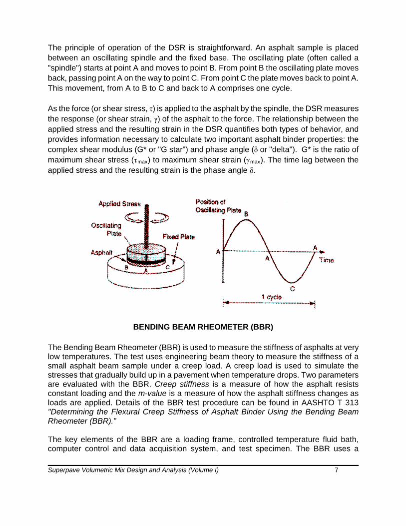
The principle of operation of the DSR is straightforward. An asphalt sample is placed between an oscillating spindle and the fixed base. The oscillating plate (often called a "spindle") starts at point A and moves to point B. From point B the oscillating plate moves back, passing point A on the way to point C. From point C the plate moves back to point A. This movement, from A to B to C and back to A comprises one cycle.
As the force (or shear stress, τ) is applied to the asphalt by the spindle, the DSR measures the response (or shear strain, γ) of the asphalt to the force. The relationship between the applied stress and the resulting strain in the DSR quantifies both types of behavior, and provides information necessary to calculate two important asphalt binder properties: the complex shear modulus (G* or "G star") and phase angle (δ or "delta"). G* is the ratio of maximum shear stress (τmax) to maximum shear strain (γmax). The time lag between the applied stress and the resulting strain is the phase angle δ.
BENDING BEAM RHEOMETER (BBR)
The Bending Beam Rheometer (BBR) is used to measure the stiffness of asphalts at very low temperatures. The test uses engineering beam theory to measure the stiffness of a small asphalt beam sample under a creep load. A creep load is used to simulate the stresses that gradually build up in a pavement when temperature drops. Two parameters are evaluated with the BBR. Creep stiffness is a measure of how the asphalt resists constant loading and the m-value is a measure of how the asphalt stiffness changes as loads are applied. Details of the BBR test procedure can be found in AASHTO T 313 "Determining the Flexural Creep Stiffness of Asphalt Binder Using the Bending Beam Rheometer (BBR).”
The key elements of the BBR are a loading frame, controlled temperature fluid bath, computer control and data acquisition system, and test specimen. The BBR uses a

Superpave Volumetric Mix Design and Analysis (Volume I) 8
blunt-nosed shaft to apply a midpoint load to the asphalt beam, which is supported at two locations. A load cell is mounted on the loading shaft, which is enclosed in an air bearing to eliminate any frictional resistance when applying load. A deflection measuring transducer is affixed to the shaft to monitor deflections. Loads are applied by pneumatic pressure and regulators are provided to adjust the load applied through the loading shaft.
The temperature bath contains a fluid consisting of ethylene glycol, methanol, and water. This fluid is circulated between the test bath and a circulating bath that controls the fluid temperature to within 0.1°C. Circulation or other bath agitation must not disturb the test specimen in a manner that would influence the testing process. The data acquisition system consists of a computer (with software) connected to the BBR for controlling test parameters and acquiring load and deflection test results.
Overview of Procedure
The operator initiates the control software before the test begins. While the test specimens are brought to test temperature in the testing bath, systems calibration and compliance are accomplished. These include calibration of the displacement transducer and load cell. Compliance of the test device is checked with a rigid stainless steel reference beam. The temperature transducer is also checked by using a calibrated mercury-in-glass thermometer. A thinner reference beam is also supplied that can be periodically used to check the performance of the overall system. This beam functions as a dummy test specimen allowing quick checks on rheometer performance. The rheometer software controls most of the system calibration and the operator need only follow the instructions provided by the software.

Superpave Volumetric Mix Design and Analysis (Volume I) 9
At the end of the 60-minute thermal conditioning period, the asphalt beam is placed on the supports by gently grasping it with forceps. A 2.5 to 4.5 gram (35 ± 10 mN) preload is manually applied by the operator to ensure that the beam is firmly in contact with the supports. A 100-gram (980 mN) seating load is automatically applied for one second by the rheometer software. After this seating, the load is automatically reduced to the preload for a 20-second recovery period. At the end of the recovery period, a 100-gram (980 ± 50 mN) load is applied to the beam for a total of 240 seconds. The deflection of the beam is recorded during this period.
As the applied load bends the beam, the deflection transducer monitors the movement. This deflection is plotted against time to determine creep stiffness and m-value. During the test, load and deflection versus time plots are continuously generated on the computer screen for the operator to observe. At the end of 240 seconds, the test load is automatically removed and the rheometer software calculates creep stiffness and m-value.
Data Presentation
Beam analysis theory is used to obtain creep stiffness of the asphalt in this test. The formula for calculating creep stiffness, S(t), is:
P L3 S(t) = -------------------- 4 b h3 Delta(t)
where: S(t) = creep stiffness at time, t = 60 seconds P = applied constant load, 100 g (980 mN) L = distance between beam supports, 102 mm b = beam width, 12.7 mm h = beam thickness, 6.35 mm Delta(t) = deflection at time, t = 60 seconds
By using the equation for S(t) and the deflection from the graph, the stiffness at time, t=60 seconds can be obtained. Creep stiffness is desired at the minimum pavement design temperature after two hours of load. However, by raising the test temperature 10°C, an equal stiffness is obtained after a 60 second loading. The obvious benefit is that a test result can be measured in a much shorter period of time.
The second parameter needed from the bending beam test is the m-value. The m-value represents the rate of change of the stiffness, S(t), versus time. This value also is calculated automatically by the BBR computer. However, to check the results from the computer, the m-value is easily obtained. To obtain m-value, the stiffness is calculated at

Superpave Volumetric Mix Design and Analysis (Volume I) 10
several loading times. These values are then plotted against time. The m-value is the slope of the log stiffness versus log time curve at any time, t.
DIRECT TENSION (DT) TESTER
The direct tension test measures the low temperature ultimate tensile strain of an asphalt binder. The test is performed at relatively low temperatures ranging from 0° to -36°C, the temperature range within which asphalt exhibits brittle behavior. Furthermore, the test is performed on binders that have been aged in a rolling thin film oven and a pressure aging vessel. Consequently, the test measures the performance characteristics of binders as if they had been exposed to hot mixing in a mixing facility and some in-service aging. Details of the DT test procedure can be found in AASHTO T 314, “Determining the Fracture Properties of Asphalt Binder in Direst Tension (DT).”
A small dog-bone shaped specimen is loaded in tension at a constant rate. The strain in the specimen at failure (Ff) is the change in length (ΔL) divided by the effective gauge length (L). In the direct tension test, failure is defined by the stress where the load on the specimen reaches it maximum value, and not necessarily the load when the specimen breaks. Failure stress (σf) is the failure load divided by the original cross section of the specimen (36 mm2).

Superpave Volumetric Mix Design and Analysis (Volume I) 11
ADDITIONAL REQUIREMENTS FOR PERFORMANCE GRADED ASPHALT BINDER
Performance graded asphalt binders (PGAB) must comply with the applicable requirements of the 2015 KDOT Standard Specifications, Section 1202 (latest revision) and AASHTO M 320 including the added requirements for polymer modified binders as shown in Table 1.3. All tests will be performed after adding 0.5% high molecular weight amine anti-stripping agent (by mass) to the PGAB. Additional information can be found in the 2015 KDOT Standard Specifications, Section 1201 (latest revision).
Table 1.3 KDOT Additional Requirements for Polymer Modified Binders
Temperature Spread1, °C 86 92 98 104 110
Separation, ASTM D5976, °C max. Run on Original Binder
2 2 22 2 2
Elastic Recovery, ASTM D6084, Procedure A, % min. Run on RTFO Residue
50 60 65 75 80
1Temperature Spread is determined by subtracting the low temperature from high temperature; for example PG 64-28: 64-(-28)=92 2For PG 70-28 RCI, separation test requirement no greater than 6.

Superpave Volumetric Mix Design and Analysis (Volume I) 12
SELECTION OF ASPHALT BINDER
The binder is selected as a function of the climate and traffic-loading conditions at the site of the paving project.
The mean and standard deviation of the yearly, 7-day-average, maximum pavement temperature 20mm below the surface of the pavement is used to determine the high temperature grade. The mean and the standard deviation of the yearly, 1-day-minimum pavement temperature, measured at the pavement surface at the site of the paving project is used to determine the low temperature grade. LTPPBind software can be used to determine these temperatures or they may be supplied by the specifying agency. The LTPP high and low temperature models should be selected in the software when determining the binder grade, if the LTPPBind software is used. When actual site data is not available, representative data from the nearest weather station is used.
The “design reliability” for the desired high and low temperature performance is selected. The design reliability required is established by agency policy. The initial cost of the materials and the subsequent maintenance costs may influence the selection of the design reliability.
The minimum PG binder that satisfies the required design reliability is then selected by using the pavement temperature data determined above.
The high temperature grade is increased by the number of grade equivalents as indicated by Table 1.4, if traffic speed or the design ESALs warrant. This adjustment takes into account the anticipated traffic conditions at the project site. The low temperature grade is not adjusted for traffic conditions.
The selected binder grade is adjusted according to Table 1.5 if reclaimed asphalt pavement (RAP) is used in the mixture. This adjustment is required in order to account for the RAP binder stiffness and quantity.
The selected binder grade is adjusted when using recycled asphalt shingles (RAS) as per Section 1103 (and/or the Special Provision for Section 1103) of the KDOT Standard Specifications. This adjustment is required in order to account for the RAS binder stiffness and quantity.

Superpave Volumetric Mix Design and Analysis (Volume I) 13
Table 1.4 Binder Selection on the Basis of Traffic Speed and Traffic Level
Design ESALs1 (million)
Adjustment to the High Temperature Grade of the Binder5
Traffic Load Rate
Standing2 Slow3 Standard4
< 0.3 Note 6 - -
0.3 to < 3 2 1 -
3 to < 10 2 1 -
10 to < 30 2 1 Note 6
≥30 2 1 1
(1) The anticipated project traffic level expected on the design lane over a 20-year period.Regardless of the actual design life of the roadway, determine the design ESALs for 20 years
(2) Standing traffic - where the average traffic speed is less than 20 km/h(3) Slow traffic - where the average traffic speed ranges from 20 to 70 km/h(4) Standard traffic - where the average traffic speed is greater than 70 km/h(5) Increase the high temperature grade by the number of grade equivalents indicated (one grade is
equivalent to 6°C). The low temperature grade is not adjusted for traffic conditions.(6) Consideration should be given to increasing the high temperature grade by one grade equivalent
Table 1.5 Binder Selection Guidelines for RAP Mixtures (see footnote #2)
Recommended Virgin Asphalt Binder Grade1 RAP Percentage
Generally, no change in binder selection2 ≤ 15
Select virgin binder based on type of construction, RAP origination and location in pavement (Major Modification/1R, surface, base or shoulder lift, etc.).2 See footnote #2 below.
16 - 25
Generally, follow recommendations from blending charts2 > 25
(1) For Commercial Grade Hot Mix Asphalt (HMA) - see Section 611 of the 2015 KDOT StandardSpecifications (latest revision)
(2) Contact KDOT’s Bureau of Road Design (Pavement Design) section for specific detailsconcerning RAP mixture design and/or see the Section 602 “Modified Requirements” in theproject contract documents

Superpave Volumetric Mix Design and Analysis (Volume I) 14
AGGREGATES
Two types of aggregate properties are specified in the Superpave system: consensus properties and source properties.
Consensus Properties
Consensus properties are those which a group of experts (named Expert Task Group) during SHRP research agreed were critical in achieving high performance HMA. These properties must be met at various levels depending on traffic level and position within the pavement. High traffic levels and surface mixtures (i.e., shallow pavement position) require more strict values for consensus properties. Many agencies already use these properties as quality requirements for aggregates used in HMA. These properties are:
• coarse aggregate angularity• fine aggregate angularity• flat or elongated particles• clay content
Coarse Aggregate Angularity
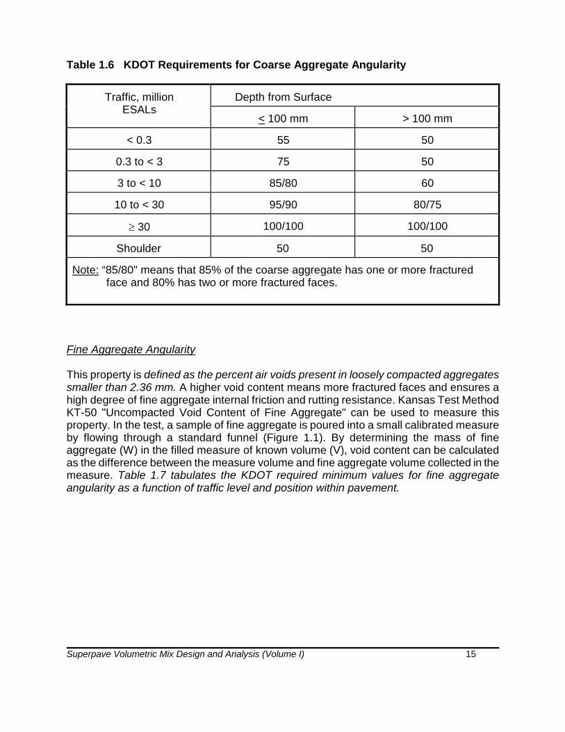
This property is defined as the percent by mass of aggregates larger than 4.75 mm with one or more fractured faces. It ensures a high degree of aggregate internal friction and rutting resistance. In Kansas, Kansas Test Method KT-31 "Determination of Crushed Particles in Crushed Gravel" is used to determine this property. Table 1.6 outlines the required minimum values for coarse aggregate angularity as a function of traffic level and position within the pavement as suggested by Superpave. These requirements have also been adopted by KDOT.
Superpave Volumetric Mix Design and Analysis (Volume I) 15
Table 1.6 KDOT Requirements for Coarse Aggregate Angularity
Traffic, million ESALs
Depth from Surface
< 100 mm > 100 mm
< 0.3 55 50
0.3 to < 3 75 50
3 to < 10 85/80 60
10 to < 30 95/90 80/75
≥ 30 100/100 100/100
Shoulder 50 50
Note: “85/80" means that 85% of the coarse aggregate has one or more fractured face and 80% has two or more fractured faces.
Fine Aggregate Angularity
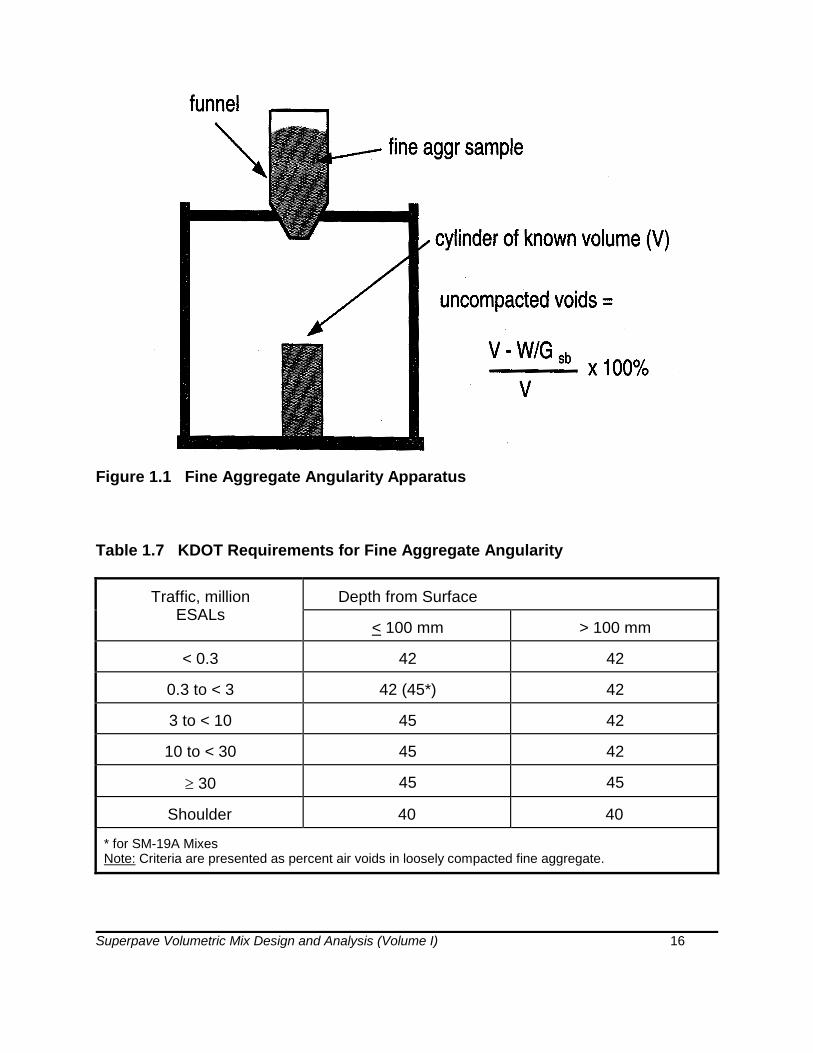
This property is defined as the percent air voids present in loosely compacted aggregates smaller than 2.36 mm. A higher void content means more fractured faces and ensures a high degree of fine aggregate internal friction and rutting resistance. Kansas Test Method KT-50 "Uncompacted Void Content of Fine Aggregate" can be used to measure this property. In the test, a sample of fine aggregate is poured into a small calibrated measure by flowing through a standard funnel (Figure 1.1). By determining the mass of fine aggregate (W) in the filled measure of known volume (V), void content can be calculated as the difference between the measure volume and fine aggregate volume collected in the measure. Table 1.7 tabulates the KDOT required minimum values for fine aggregate angularity as a function of traffic level and position within pavement.
Superpave Volumetric Mix Design and Analysis (Volume I) 16
Figure 1.1 Fine Aggregate Angularity Apparatus
Table 1.7 KDOT Requirements for Fine Aggregate Angularity
Traffic, million ESALs
Depth from Surface
< 100 mm > 100 mm
< 0.3 42 42
0.3 to < 3 42 (45*) 42
3 to < 10 45 42
10 to < 30 45 42
≥ 30 45 45
Shoulder 40 40
* for SM-19A MixesNote: Criteria are presented as percent air voids in loosely compacted fine aggregate.

Superpave Volumetric Mix Design and Analysis (Volume I) 17
Flat and Elongated Particles
This characteristic, according to Superpave, is the percentage by mass of coarse aggregates that have a maximum to minimum dimension of greater than five. Elongated particles are undesirable because they have a tendency to break during construction and under traffic. The test procedure used is KT-59, "Flat and Elongated Particles in Coarse Aggregate" and is performed on coarse aggregate larger than 4.75 mm. The KDOT requirements for flat and elongated particles are shown in Table 1.8.
Table 1.8 KDOT Requirements for Flat and Elongated Particles for HMA
Traffic, million ESALs Maximum, Percent
All Traffic Levels 10
Note: Criteria are presented as maximum percent by mass of flat and elongated particles.
Clay Content (Sand Equivalent)
Clay content (commonly known as “Sand Equivalent”) is the percentage of clay material contained in the aggregate fraction that is finer than a 4.75 mm sieve. It is measured by KT-55, "Plastic Fines in Combined Aggregates by Use of the Sand Equivalent Test" which has been derived from one specific test procedure covered in AASHTO T 176 (air dry and mechanical shaking). In this test, a sample of fine aggregate is placed in a graduated cylinder with a flocculating solution and agitated with a mechanical shaker to loosen clayey fines present in and coating the aggregate. The flocculating solution forces the clayey material into suspension above the granular aggregate. After a period that allows sedimentation, the heights of suspended clay and settled sand levels are read in the graduated cylinder and noted (Figure 1.2). The sand equivalent value is computed as a ratio of the sand to clay height readings expressed as a percentage. Table 1.9 lists the current sand equivalent requirements of KDOT based on the design traffic (ESALs) on the project.

Superpave Volumetric Mix Design and Analysis (Volume I) 18
Figure 1.2 Sand Equivalent Test
Table 1.9 KDOT Clay Content (Sand Equivalent) Criteria
Traffic, million ESALs Sand Equivalent minimum, percent
< 0.3 40
0.3 to < 3 40
3 to < 10 45
10 to < 30 45
≥ 30 50
Shoulder 40

Superpave Volumetric Mix Design and Analysis (Volume I) 19
Source Properties
The source properties are those which agencies often use to qualify local sources of aggregate. The source properties are:
• toughness• soundness• deleterious materials
Toughness
Toughness is the resistance of coarse aggregate to abrasion and degradation and is measured by the Los Angeles abrasion test (AASHTO T 96 or ASTM C131 or C535). This test estimates the mechanical degradation of aggregates during handling, construction, and in-service. It is performed by subjecting the coarse aggregate, usually larger than 2.36 mm, to impact and grinding by steel spheres. The test result is percent loss, which is the mass percentage of coarse material lost during the test as a result of the mechanical degradation. KDOT follows AASHTO T 96 except that the test sample should be prepared by removing the material passing 0.075 mm sieve, mud or clay lumps and sticks. The maximum permitted loss value for KDOT mixtures is 40 percent.
Soundness
Soundness is the percent loss of materials from an aggregate blend during the sodium sulfate soundness test. The procedure is stated in AASHTO T 104 or ASTM C88. This test estimates the resistance of aggregate to weathering while in service. It can be performed on both coarse and fine aggregate. The test is performed by alternately exposing an aggregate sample to repeated immersions in saturated solutions of sodium or magnesium sulfate each followed by oven drying. One immersion and drying is considered one soundness cycle. During the drying phase, salts precipitate in the permeable void space of the aggregate. Upon re-immersion the salt rehydrates and exerts expansive forces that simulate the expansive forces of freezing water. The test result is total percent loss over various sieve intervals for a required number of cycles. Maximum loss values range from approximately 10 to 20 percent for five cycles.
In Kansas, however, the soundness is evaluated by KDOT with the "Soundness Test for Aggregates," as listed in Section 1115 (Test Methods for Division 1100, Aggregates) of the 2015 KDOT Standard Specifications for State Road and Bridge Construction. The minimum acceptable soundness value obtained from this test is 0.90.

Superpave Volumetric Mix Design and Analysis (Volume I) 20
Deleterious Materials
Deleterious materials are defined as the mass percentage of contaminants such as shale, wood, mica, and coal in the blended aggregate. This property is measured by AASHTO T 112 or ASTM C412. It can be performed on both coarse and fine aggregate. Kansas has several test methods to determine amounts of different deleterious materials:
KT-7 Clay lumps in aggregates KT-8 Shale or "Shale like" materials in aggregate KT-35 Sticks in aggregate
KDOT requirements for these deleterious materials are outlined in Section 1103 (Aggregates for Hot Mix Asphalt) of the 2015 KDOT Standard Specifications for State Road and Bridge Construction.
Other Properties
In addition to these aggregate properties, specific gravities of the aggregates (bulk and apparent) to be used in a mix design, need to be evaluated. In Kansas, these are determined by Kansas Test Method KT-6; Specific Gravity and Absorption of Aggregates. KT-6 reflects testing procedures found in AASHTO T 84 and T 85.
Gradation
To specify gradation, Superpave utilized a 0.45 power gradation chart to define a permissible gradation. This chart uses a unique graphing technique to judge the cumulative particle size distribution of a blend of aggregates. The ordinate of the chart is percent passing. The abscissa is an arithmetic scale of sieve size in millimeters, raised to the 0.45 power. Figure 1.3 illustrates how the abscissa is scaled. In this example, the 4.75 mm sieve is plotted at 2.02, which is the sieve size raised to 0.45 power. Normal 0.45 power charts do not show arithmetic abscissa labels such as those in Figure 1.3. Instead, the scale is annotated with the actual sieve size as shown in Figure 1.4. An important feature of this chart is the maximum density gradation. This gradation plots as a straight line from the maximum aggregate size through the origin.

Superpave Volumetric Mix Design and Analysis (Volume I) 21
Figure 1.3 Basis for 0.45 Power Chart
Superpave uses the following definitions with respect to aggregate size:
Nominal Maximum Size: One sieve size larger than the first sieve to retain more than 10 percent.
Maximum Size: One sieve size larger than the nominal maximum size.
The maximum density gradation (Figure 1.4) represents a gradation wherein the aggregate particles fit together in the densest possible arrangement. Clearly this is a gradation to avoid because there would be very little aggregate space within to develop sufficiently thick asphalt films for a durable mixture. Figure 1.4 shows a 0.45 power gradation chart with a maximum density gradation for a 19 mm maximum aggregate size or 12.5 nominal maximum aggregate size.

Superpave Volumetric Mix Design and Analysis (Volume I) 22
Figure 1.4 Maximum Density Gradation for 19-mm Maximum Aggregate Size or 12.5-mm Nominal Maximum Aggregate Size
To specify aggregate gradation, control points are added to the 0.45 power chart. Control points function as the master ranges through which gradations must pass and are placed on:
• maximum size• nominal maximum size• an intermediate size (2.36 mm)• dust size (0.075 mm)
The term used to describe the cumulative frequency distribution of aggregate particle sizes is the design aggregate structure. A design aggregate structure lies between the control points and meets the requirements of Superpave with respect to gradation. Superpave defines six mixture gradations by their nominal maximum aggregate sizes as shown in Table 1.10. Detailed gradations (control points) for the mixture sizes used in Kansas are shown in Appendix A. Figure 1.5 illustrate the control points for a 12.5-mm nominal maximum aggregate size Superpave mixture. Table 1.11 lists the numerical gradation limits (% retained) for the designated Superpave mixtures for the major modification and 1R overlay projects in Kansas which incorporate the control points described by Superpave. KDOT includes the nominal maximum aggregate size in the name of each mix designation; mixes ending in A (such as, SM-9.5A) go above the maximum density line in the sieve sizes. Mixes ending in B or T (such as, SM-9.5B or SM-9.5T) go below the maximum density line in the sieve sizes.

Superpave Volumetric Mix Design and Analysis (Volume I) 23
Table 1.10 Superpave Mixture Sizes
Superpave Designation
Nominal Maximum Size, mm
Maximum Size, mm
37.5 mm 37.5 50
25 mm 25 37.5
19 mm 19 25
12.5 mm 12.5 19
9.5 mm 9.5 12.5
4.75 mm 4.75 9.5
Figure 1.5 Superpave Gradation Limits for a 12.5-mm Nominal Maximum Aggregate Size Mixture

Superpave Volumetric Mix Design and Analysis (Volume I) 24
Table 1.11 KDOT Superpave Mixture Gradations (Single Point Design Limits, % Retained) for Major Modification and 1R Overlay Projects *
Nominal Maximum Size Mix
Designation
Percent Retained – Square Mesh Sieves
37.5 mm (1½” )
25.0 mm (1”)
19.0 mm (3/4”)
12.5 mm (1/2”)
9.5 mm (3/8”)
4.75 mm (#4)
2.36 mm (#8)
1.18 mm (#16)
75 µm (#200)
SM-4.75A SR-4.75A 0
0 0-2
0-50-5
0-100-10
40-7040-70
88-9488-94
SM-9.5A SR-9.5A 0
0 0-2
0-100-10
10 min 10 min
33-5333-53
90-9890-98
SM-9.5B SR-9.5B 0
0 0-2
0-100-10
10 min 10 min
53-6853-68
90-9890-98
SM-9.5T SR-9.5T 0
0 0-2
0-100-10
10 min 10 min
53-6853-68
90-9890-98
SM-12.5A SR-12.5A 0
0 0-2
0-100-10
10 min 10 min
42-6142-61
90-9890-98
SM-12.5B SR-12.5B 0
0 0-2
0-100-10
10 min 10 min
61-7261-72
90-9890-98
SM-19A SR-19A 0
0 0-2
0-100-10
10 min 10 min
51-6551-65
92-9892-98
SM-19B SR-19B 0
0 0-2
0-100-10
10 min 10 min
65-7765-77
92-9892-98
*Confirm table values using Table 602-1 in Section 602 of the 2015 KDOT Standard Specifications.
Superpave Volumetric Mix Design and Analysis (Volume I) 25
Aggregate Blending
Usually, several aggregates need to be blended to produce trial blends that would result in design aggregate structure. A trial-and-error approach is generally used to determine the proportions of the individual aggregates in the blend. The basic mathematical equation for blending is:
% Retained = A * a + B * b + C * c + …...
where: A,B,C, = percent retained on a given sieve for each aggregate; and
a,b,c, = proportion (decimal fraction) of each aggregate being considered for use in the blend
note that: a + b + c + ...... = 1.0
Table 1.12 shows the calculations for two aggregates. The table shows the required specification range and the desired (target) gradation, usually the midpoint of the specification range. A trial percentage of each aggregate source is usually assumed and multiplied by the percent retained on each sieve. These gradations are then added to get the composite percent retained on each sieve for the blend. The gradation of the blend is compared to the specification range to determine if the blend is acceptable. These calculations are easily performed by a spreadsheet computer program.

Superpave Volumetric Mix Design and Analysis (Volume I) 26
Table 1.12 Aggregate Blending Example
% Retained on Sieve
1/2" 3/8" #4 #8 #30 #100 #200
Specification 0 0-5 15-30 30-45 60-80 80-90 92-96
Target Gradation 0 2.5 22.5 27.5 70 85 94
Coarse Sand (A)* 0 0 2 10 29 58 81
Crushed Rock (B)* 0 6 30 51 86 98 99
30% A (a)* 0 0 0.6 3 8.7 17.4 24.3
70% B (b)* 0 4.2 21 35.7 60.2 68.6 69.3
Blend 0 4 22 38 69 86 94
* Letters in ( ) refer to letters in the equations on the previous page

Superpave Volumetric Mix Design and Analysis (Volume I) 27
Properties of Blended Aggregate
When two or more aggregates from different sources are blended, some of the properties of the blend can be calculated from the properties of individual aggregates. With the exception of specific gravity, the properties (such as, angularity, absorption, strength, etc.) of the blend are the simple weighted averages of the properties of individual aggregates as shown in the equation below:
X = P1 * X1 + P2 * X2 + P3 * X3 + .........
where: X = composite property of the blend X1 , X2 , X3 = properties of fractions 1, 2, and 3 P1 , P2, P3 = decimal fractions by weight of aggregates 1, 2, and 3, used in
the blend
Example Problem: Fine aggregates from two sources having fine aggregate angularity (FAA) values of 40 and 47 were blended at a ratio of 30:70 by weight, respectively. What is the FAA value of the blend?
Blend FAA = 0.30 * 40 + 0.70 * 47 = 45
Superpave Volumetric Mix Design and Analysis (Volume I) 28
CHAPTER II
ASPHALT MIXTURE VOLUMETRICS
Introduction
Asphalt mixture volumetrics, or in other words, volumetric proportions of asphalt binder and aggregate components, play a significant role in asphalt mixture behavior. Thus, a volumetric mixture design protocol was developed to consider volumetric properties of Superpave mixtures.
The volumetric properties of a compacted paving mixture [air voids (Va), voids in the mineral aggregate (VMA) and voids filled with asphalt (VFA)] provide some indications of the mixture's potential pavement service performance. It is necessary to understand the definitions and analytical procedures described in this chapter to be able to make informed decisions concerning the selection of the design asphalt mixture. The information provided here applies to both paving mixtures that have been compacted in the laboratory, and to undisturbed samples that have been cut from a pavement in the field (cores/beams).
Terminology & Formulas
Mineral aggregate is porous and can absorb water and asphalt to a variable degree. Furthermore, the ratio of water to asphalt absorption varies with each aggregate. The three methods of measuring aggregate specific gravity take these variations into consideration. These methods yield bulk, apparent, and effective specific gravities.
Bulk Specific Gravity, Gsb - the ratio of the mass in air of a unit volume of a permeable material (including both permeable and impermeable voids normal to the material) at a stated temperature to the mass in air of an equal volume of gas-free distilled water at a stated temperature. Bulk specific gravity (AASHTO T84 & T85/KT-6) is determined by measuring the dry mass and bulk volume of an aggregate sample. The bulk volume includes the solid aggregate volume plus the volume of surface pores holding water (i.e., Bulk Volume = solid volume + water permeable pore volume) as shown in Figure 2.1.
When an aggregate blend consists of separate fractions of coarse and fine aggregates, all having different specific gravities as in the case of a compacted or loose asphalt mixture, the bulk specific gravity for the aggregate blend is calculated using the formula:
+++
+++=
n
n
nsb
GP
GP
GP
PPPG
...
)...(
2
2
1
1
21 (2.1)

Superpave Volumetric Mix Design and Analysis (Volume I) 29
Figure 2.1 Specific Gravities of the Aggregates
where: Gsb = bulk specific gravity for the aggregate blend P1, P2,…, Pn = individual percentages by mass of aggregate G1, G2,…, Gn = individual bulk specific gravities of aggregate
note that: P1 + P2 +......+ Pn = 100%
Example: What is the bulk specific gravity for the aggregate blend consisting of three different types of aggregates; CS-1: 65%, CS-2: 12% and sand: 23%? The bulk specific gravities for the aggregates are CS-1: 2.65; CS-2: 2.71; and sand: 2.69.
P1 = 65 P2 = 12 P3 = 23 G1 = 2.65 G2 = 2.71 G3 = 2.69
++
++=
69.223
71.212
65.265
)231265(sbG
Gsb = 2.666
Apparent Specific Gravity, Gsa - the ratio of the mass in air of a unit volume of an impermeable material at a stated temperature to the mass in air of an equal volume of gas-free distilled water at a stated temperature. Apparent specific gravity (also measured using KT-6) is determined by measuring the dry mass and apparent volume of an aggregate sample. The apparent volume only includes the volume of the solid aggregate and does not include the volume of any surface pores (i.e., apparent volume = volume of solid aggregate particles) as shown in Figure 2.1.
Superpave Volumetric Mix Design and Analysis (Volume I) 30
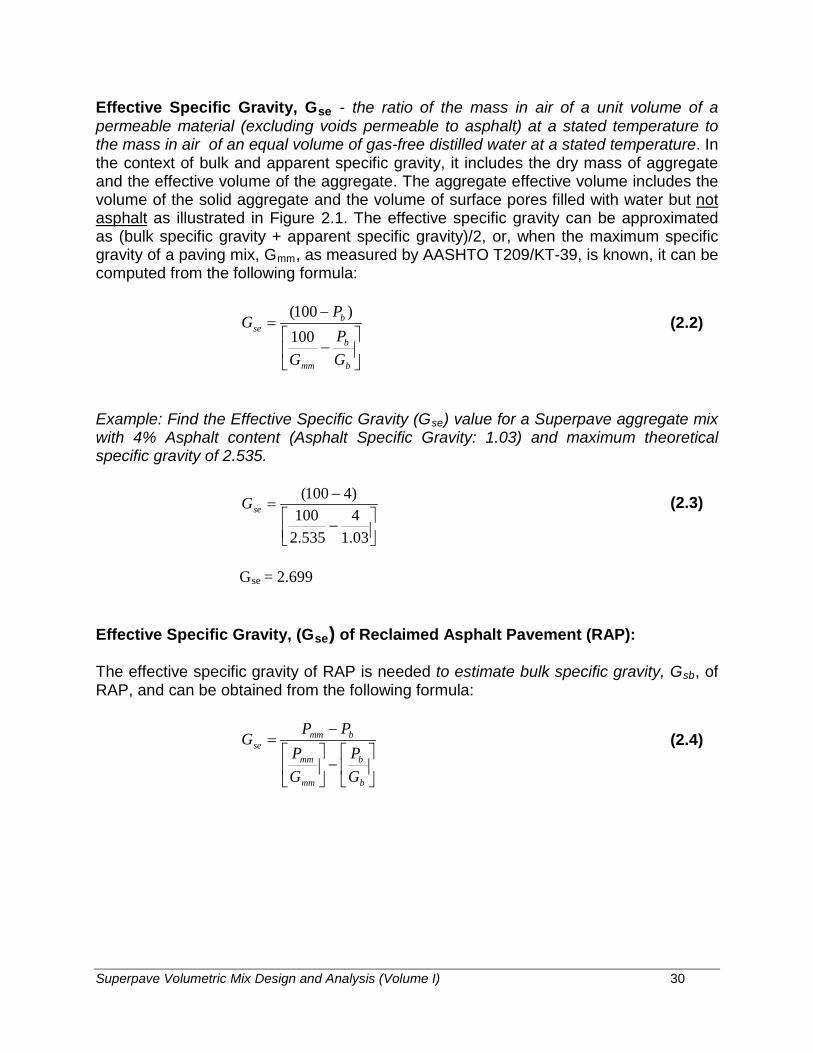
Effective Specific Gravity, Gse - the ratio of the mass in air of a unit volume of a permeable material (excluding voids permeable to asphalt) at a stated temperature to the mass in air of an equal volume of gas-free distilled water at a stated temperature. In the context of bulk and apparent specific gravity, it includes the dry mass of aggregate and the effective volume of the aggregate. The aggregate effective volume includes the volume of the solid aggregate and the volume of surface pores filled with water but not asphalt as illustrated in Figure 2.1. The effective specific gravity can be approximated as (bulk specific gravity + apparent specific gravity)/2, or, when the maximum specific gravity of a paving mix, Gmm, as measured by AASHTO T209/KT-39, is known, it can be computed from the following formula:
−
−=
b
b
mm
bse
GP
G
PG
100)100(
(2.2)
Example: Find the Effective Specific Gravity (Gse) value for a Superpave aggregate mix with 4% Asphalt content (Asphalt Specific Gravity: 1.03) and maximum theoretical specific gravity of 2.535.
−
−=
03.14
535.2100
)4100(seG (2.3)
Gse = 2.699
Effective Specific Gravity, (Gse) of Reclaimed Asphalt Pavement (RAP):
The effective specific gravity of RAP is needed to estimate bulk specific gravity, Gsb, of RAP, and can be obtained from the following formula:
−
−
=
b
b
mm
mm
bmmse
GP
GP
PPG (2.4)

Superpave Volumetric Mix Design and Analysis (Volume I) 31
where: Gse = effective specific gravity of RAP Pmm = total loose mixture = 100% Pb = asphalt, percent by total weight of mixture (obtained by burning
asphalt in RAP using KT-57) Gmm = maximum specific gravity of RAP (no air voids) (KT-39) Gb = Specific gravity of the asphalt in the RAP (1.035 estimated)
Two specific gravities of the asphalt mixture will be of use in the Superpave volumetric mix design. They are: maximum theoretical specific gravity of loose asphalt mix and bulk specific gravity of compacted mix.
Maximum Theoretical Specific Gravity of loose asphalt mix, Gmm - the ratio of the mass of a given volume of HMA with no air voids to the mass of an equal volume of water, both at the same temperature. This specific gravity of a loose asphalt mixture, also known as Rice Specific Gravity, can be determined by AASHTO T209/KT-39, or can be estimated from the following formula for a given mix:
+
=
b
b
se
smm
GP
GP
G 100 (2.5)
where: Gmm = maximum theoretical specific gravity Gse = effective specific gravity of the aggregate blend Gb = specific gravity of the asphalt Ps = percentage of aggregate (= 100 - Pb) Pb = percent asphalt (total mixture basis)
Example: Compute the Maximum Theoretical Specific Gravity (Gmm) for a bituminous mix composed of 96% aggregates and 4% asphalt (asphalt specific gravity = 1.03). The effective specific gravity of the asphalt mix is 2.699.
Gse = 2.699 Gb = 1.03 Pb =4% Ps= (100 - 4) = 96%
+
=
03.14
699.296
100mmG
Gmm= 2.535
Superpave Volumetric Mix Design and Analysis (Volume I) 32
Compacted Mixture Bulk Specific Gravity (Gmb) - the ratio of the mass of a given volume of HMA to the mass of an equal volume of water, both at the same temperature. The knowledge of bulk specific gravity of a compacted asphalt mix (Gmb) is essential for computing certain volumetric parameters, such as, percent air voids. This specific gravity can be determined using AASHTO T166 (Method A)/KT-15 (Procedure III) and is expressed as:
Gmb = A / (B-C) (2.6)
where: A = Mass of dry specimen in air, g. B = Mass of the saturated, surface dry (SSD) specimen in air after 4
minutes in water, g. C = Mass of saturated specimen in water, g.
Example: Find the bulk specific gravity of a compacted asphalt mixture specimen from the following data:
Mass of dry specimen in air, A = 4,847g Mass of SSD specimen in air after 4 minutes in water, B = 4,875g Mass of SSD specimen in water, C = 2,890g
Gmb = 4847/(4875 - 2890) = 2.442
The definitions for voids in the mineral aggregate (VMA), air voids (Va), voids filled with asphalt (VFA) and effective asphalt content (Pbe) are:
Voids in the Mineral Aggregate, VMA - the volume of intergranular void spaces between the aggregate particles of a compacted paving mixture that includes the air voids and the effective asphalt content, expressed as a percent of the total volume of the sample. The volume fractions are shown in Figure 2.2.
VMA can be computed using the following formula:
−=
sb
smb
GPG
VMA)(
100 (2.7)

Superpave Volumetric Mix Design and Analysis (Volume I) 33
Vma = Volume of voids in mineral aggregate Vmb = Bulk volume of compacted mix Vmm = Voidless volume of paving mix Vfa = Volume of voids filled with asphalt Va = Volume of air voids Vb = Volume of asphalt Vba = Volume of absorbed asphalt Vsb = Volume of mineral aggregate (by bulk specific gravity) Vse = Volume of mineral aggregate (by effective specific gravity)
Figure 2.2 Volume Fractions of a Compacted Asphalt Concrete Mix
Example: Find the VMA value using previously obtained Gmb and Gsb values and for a mix with 4% asphalt content (i.e. 96% aggregate, Ps).
×
−=666.2
96442.2100VMA
VMA = 12.07 %
Vma
Vsb aggregate
asphalt Vfa
Vba
air Va
Vb
Vse
Vmm Vmb

Superpave Volumetric Mix Design and Analysis (Volume I) 34
Percent Absorbed Asphalt, Pba - the portion of asphalt absorbed into the aggregate and can be computed as:
)())(100(
sesb
sbsebba GG
GGGP
−= (2.8)
Example: Find the Pba for the previously obtained data.
)666.2699.2()666.2699.2)(03.1100(
×−×
=baP
Pba = 0.5%
Effective Asphalt Content, Pbe - the total asphalt content of a paving mixture minus the portion of asphalt absorbed into the aggregate particles:
×
−=100
)( sbabbe
PPPP (2.9)
Example: Find the value of Pbe for the previously obtained data.
×
−=100
)965.0(0.4beP (2.10)
Pbe = 3.52%
Air Voids, Va - the total volume of the small pockets of air between the coated aggregate particles throughout a compacted paving mixture, expressed as percent of the bulk volume of the compacted paving mixture and can be computed from the following formula:
−×=
mm
mbmma G
GGV )( 100 (2.11)

Superpave Volumetric Mix Design and Analysis (Volume I) 35
Example: Find the percent air void for the previously computed Gmm and Gmb values.
−
×=535.2
)442.2535.2( 100aV
Va = 3.7%
Voids Filled with Asphalt, VFA - the percentage portion of the volume of intergranular void space between the aggregate particles that is occupied by the effective asphalt. It is expressed as the ratio of (VMA - Va) to VMA as shown below:
−
×=VMA
VVMAVFA a 100 (2.12)
Example: Find out the VFA value for previously computed VMA and percent air void values.
−
×=07.12
7.307.12 100VFA
VFA = 69.3%
In Superpave data analysis, voids in the mineral aggregate (VMA) and air voids (Va) are expressed as percent by volume of the paving mixture. Voids filled with asphalt (VFA) are the percentage of VMA filled by the effective asphalt. Depending on how asphalt content is specified, the effective asphalt content may be expressed either as percent by mass of the total mass of the paving mixture, or as percent by mass of the aggregate in the paving mixture.
Because air voids, VMA and VFA are volume quantities and therefore cannot be weighed, a paving mixture must first be designed or analyzed on a volume basis. For design purposes, this volume approach can easily be changed over to a mass basis to provide a job-mix formula.

Superpave Volumetric Mix Design and Analysis (Volume I) 36
Superpave Volumetric Asphalt Mixture Design Requirements
The asphalt mixture design requirements in the Superpave volumetric method consist of:
• Mixture volumetric requirements• Compactibility requirements• Dust proportion (Dust to Binder Ratio)• Moisture susceptibility
Specified values for these parameters are applied during the Superpave volumetric mixture design phase.
Mixture Volumetric Requirements
Mixture volumetric requirements consist of air voids (Va), voids in the mineral aggregate (VMA) and voids filled with asphalt (VFA). Air void content is an important property because it is used as the basis for asphalt binder content selection. In all cases, the design air void content is four percent. VMA requirements are a function of maximum nominal aggregate size of the mixture. VFA requirements are a function of traffic level (design ESALs). VMA and VFA requirements in Superpave will be discussed in detail in the next chapter.
Compactibility Requirements
These requirements are based on % Gmm obtained during gyratory compaction of the Superpave samples at Nini and Nmax levels of gyration. %Gmm at Nini level is a function of traffic level (design ESALs) and %Gmm at Nmax level is capped at less than 98% maximum.
Dust Proportion (Dust to Binder Ratio)
Dust proportion, also known as the dust to binder ratio, is an indicator of amount of material passing 75 µm (U.S. No. 200) sieve (P0.075) with respect to the effective asphalt content (Pbe) and computed using the following formula:
=
bePP
DP 075. (2.13)
An acceptable dust proportion ranges from 0.6 to 1.2, 0.8 to 1.6 or 0.9 to 2.0 depending upon mixture type and/or size (see Table 602-1 in the Special Provision to Section 602 of the 2015 KDOT Standard Specifications (latest revision)).
Superpave Volumetric Mix Design and Analysis (Volume I) 37
Moisture Susceptibility
The test used to evaluate Superpave HMA for moisture susceptibility, or stripping, in Kansas is Kansas Test Method KT-56; Resistance of Compacted Asphalt Mixtures to Moisture Induced Damage. This test is not a performance-based test. It serves two purposes. First, it identifies whether an asphalt-aggregate mixture is moisture susceptible. Second, it measures the effect of anti-stripping additives. In this test, two subsets of test specimens are produced from a loose mixture at design asphalt content found in volumetric mixture design. One set is kept at room temperature. The other set is subjected to water conditioning. After conditioning, both subsets are tested for indirect tensile strength at 25ºC. The test result reported is the ratio of average tensile strength of the conditioned subset to that of the unconditioned subset. This ratio is called the "tensile strength ratio," or TSR. Superpave requires a minimum TSR of 0.8 (80 percent); KDOT follows this requirement.
Steps in the Analysis of a Compacted Paving Mixture
The measurements and calculations needed for a voids analysis are:
(a) Measure the bulk specific gravities of the coarse aggregate (AASHTOT85/KT-6) and of the fine aggregate (AASHTO T84/KT-6) or use the valuedetermined via 3-way split analysis and/or published value.
(b) Measure the specific gravity of the asphalt binder (AASHTO T228 orASTM D70). (usually obtained from the asphalt binder supplier).
(c) Calculate the bulk specific gravity (Gsb) of the aggregate blend in thepaving mixture.
(d) Measure the maximum specific gravity (Gmm) of the loose paving mixture(AASHTO T 209/KT-39).
(e) Measure the bulk specific gravity (Gmb) of the compacted paving mixture(AASHTO T 166/KT-15).
(f) Calculate the effective specific gravity (Gse) of the aggregate blend.
(g) Calculate the maximum specific gravity (Gmm) at other asphalt contents.
(h) Calculate the asphalt absorption (Pba) of the aggregate.
(i) Calculate the effective asphalt content (Pbe) of the paving mixture.
(j) Calculate the percent voids in the mineral aggregate (VMA) in thecompacted paving mixture.
(k) Calculate the percent air voids (Va) in the compacted paving mixture.
(l) Calculate the percent voids filled with asphalt (VFA) in the compactedpaving mixture.
Superpave Volumetric Mix Design and Analysis (Volume I) 38
CHAPTER III
SUPERPAVE GYRATORY COMPACTION
Introduction
Superpave mixture design uses the Superpave Gyratory Compactor (SGC) to realistically compact loose mixture specimens to densities achieved under actual pavement climatic and loading conditions.
Test Equipment
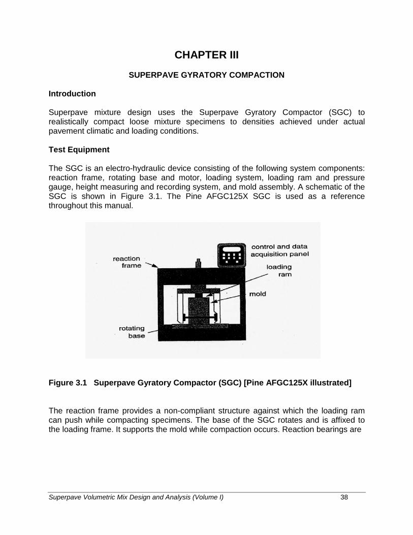
The SGC is an electro-hydraulic device consisting of the following system components: reaction frame, rotating base and motor, loading system, loading ram and pressure gauge, height measuring and recording system, and mold assembly. A schematic of the SGC is shown in Figure 3.1. The Pine AFGC125X SGC is used as a reference throughout this manual.
Figure 3.1 Superpave Gyratory Compactor (SGC) [Pine AFGC125X illustrated]
The reaction frame provides a non-compliant structure against which the loading ram can push while compacting specimens. The base of the SGC rotates and is affixed to the loading frame. It supports the mold while compaction occurs. Reaction bearings are

Superpave Volumetric Mix Design and Analysis (Volume I) 39
used to position the mold at an internal angle of 1.16 ± 0.02 degrees which is the compaction angle of the SGC. The electric motor drives the rotating base at a constant speed of 30 ± 0.5 revolutions per minute as well as furnishes power to the hydraulic system. A hydraulic or mechanical system applies a load to the loading ram which imparts 600 ± 18 kPa compaction pressure to the specimen. The loading ram diameter nominally matches the inside diameter of the mold, which is usually 150 mm. A pressure gauge with digital signal conditioning measures the ram pressure during compaction. As the specimen densifies during compaction, the pressure gauge signals the hydraulic system to adjust the position of the loading ram so that a constant compaction pressure is maintained.
Specimen height measurement is an important function of the SGC. By knowing the mass of material placed in the mold, the diameter of the mold, and the specimen height, an estimate of specimen density can be made at any time throughout the compaction process. Density is computed by dividing the mass by the volume of the specimen. The specimen volume is calculated as the volume of a cylinder with a diameter of 150 mm and the measured height. Height is recorded by means of a Linear Variable Differential Transformer (LVDT) (or equivalent) that records the position of the ram before and during the test. The vertical change in ram position identically equals the change in specimen height. The specimen height vs. the number of gyrations is available through a serial port connection which may be connected to a personal computer, printer, or other device to record height (i.e., density) measurements throughout the compaction process. By this method, a compaction characteristic is developed as the specimen is compacted (Figure 3.2).
Figure 3.2 Compaction Characteristic of SGC

Superpave Volumetric Mix Design and Analysis (Volume I) 40
The SGC uses a cast steel mold (Figure 3.3) with a diameter of 150 mm and a nominal height of 250 mm. A base plate fits in the bottom of the mold to allow specimen confinement during compaction.
Figure 3.3 SGC Mold Configuration
Specimen Preparation
Compaction specimens are required to be mixed and compacted under equi-viscous temperature conditions corresponding to 0.170 +/-0.02 Pa⋅s and 0.280 +/-0.03 Pa⋅s, respectively. Figure 3.4 shows a typical temperature-viscosity chart for an asphalt binder. Mixing is accomplished by a mechanical mixer. After mixing in the lab, loose test specimens are subjected to 2 hours +/- 5 minutes of short term aging in a forced draft oven maintained at the compaction temperature. The compaction molds and base plates should also be placed in an oven at compaction temperature for at least 30 to 45 minutes prior to use.
Figure 3.4 Typical Temperature-Viscosity Relationship

Superpave Volumetric Mix Design and Analysis (Volume I) 41
Selection of Design Aggregate Structure
One of the preliminary steps in Superpave mixture design is to select the design aggregate structure. Trial blends are established by mathematically combining the gradations of individual aggregates into a single gradation. The blend gradation is then compared to the specification control requirements for the appropriate sieves as required by Superpave.
As a minimum, three trial blends need to be evaluated - one coarse, one fine and one intermediate. Once trial blends are selected, a preliminary evaluation of the blended aggregate properties is necessary. This includes the four consensus properties, the bulk and apparent specific gravities of the aggregates, and any source aggregate properties. These values are mathematically combined from the individual aggregate properties.
After the aggregate properties have been evaluated, the next step is to compact specimens and determine the initial volumetric properties of each trial blend. However, this requires an estimation of a trial (initial) binder (asphalt) content.
Estimation of Trial (Initial) Binder Content
The trial (initial) binder content is estimated from the knowledge of effective specific gravity and absorption of the aggregate blend. This trial binder content is then estimated as described in Superpave Level I Mix Design, published as Superpave Series No. 2 (SP-2) by The Asphalt Institute, Lexington, Kentucky or AASHTO Standard Practice, AASHTO Designation R 35, Superpave Volumetric Design for Hot-Mix Asphalt (HMA). The following procedure can be followed to estimate the trial binder content for each aggregate blend:
The effective specific gravity (Gse) of the blend is estimated using the equation:
Gse = Gsb + 0.8 * (Gsa - Gsb) (3.1)
where: Gse = effective specific gravity of the aggregate blend Gsb = bulk specific gravity of the aggregate blend Gsa = apparent specific gravity of the aggregate blend
The multiplier, 0.8, can be changed at the discretion of the designer. Absorptive aggregates may require values closer to 0.6 or 0.5.
The volume of asphalt binder absorbed into the aggregates (Vba) is estimated from the equation:

Superpave Volumetric Mix Design and Analysis (Volume I) 42
−×
+
−×=
sesb
se
s
b
b
asba GG
GP
GP
VPV 11 )1( (3.2)
where: Vba = volume of absorbed binder, cm3/cm3 of mix Pb = percent of binder (assumed 0.05), Ps = percent of aggregate (assumed 0.95), Gb = specific gravity of binder (assumed 1.02, if not known), Va = volume of air voids (assumed 0.04 cm3/cm3 of mix)
The volume of the effective binder (Vbe) is then determined as:
Vbe = 0.176 - 0.0675* log (Sn) (3.3)
where: Sn = the nominal maximum sieve size of the aggregate blend (in mm)
Finally, the trial (initial) asphalt binder (Pbi) content is calculated from the equation:
100 ))((
)( ×
++×+×
=sbabeb
babebbi WVVG
VVGP (3.4)
where: Pbi = percent of binder by mass of mix, and Ws = mass of aggregate, grams, from the equation below:
+
−×=
se
s
b
b
ass
GP
GP
VPW )1( (3.5)

Superpave Volumetric Mix Design and Analysis (Volume I) 43
A minimum of two specimens for each trial blend is compacted using the SGC. Two different asphalt mixture quantities are needed. For specimens to be used in the volumetric design, sufficient mix to achieve a specimen 150 mm in diameter by approximately 115 mm height needs to be compacted. Each specimen requires approximately 4,500 grams of aggregate. At least one loose sample should be prepared to obtain a maximum theoretical specific gravity using KT-39/AASHTO T209. Approximately 2,000 grams of aggregate are needed for one sample in this test.
Overview of Procedure
After short-term aging (lab produced mix only) for 2 hours at compaction temperature in the oven, the loose test specimens are ready for compaction. The compactor is initiated by turning on its main power. The vertical pressure is set at 600 kPa. The gyration counter should be set to the desired number of gyrations. Three gyration levels are of interest:
• initial number of gyrations (Nini)• design number of gyrations (Ndes)• maximum number of gyrations (Nmax)
Test specimens are compacted using Nmax gyrations. The relationship between Nini, Ndes and Nmax are:
Log Nmax =1.10 Log Ndes (3.6)Log Nini = 0.45 Log Ndes (3.7)
The design number of gyrations (Ndes) is a function of the project traffic level (20-year design ESALs). The values for Ndes are shown in the Table 3.1 and range from 50 to 125. The contract documents for a KDOT project will have the Ndes, Nini and Nmaxvalues for that project determined from the design traffic level.
After the base plate is in place, a paper disk is placed on top of the plate and the mold is charged in a single lift. The top of the uncompacted specimen should be leveled off. The mix is to be at the midpoint of the established binder compaction temperature range. A paper disk is placed on top of the mixture, followed by the top plate.
The mold is placed in the compactor on the rollers. After the machine is started, the ram is automatically lowered until it contacts the mixture and the resisting pressure is 600 kPa. The angle of gyration (1.16 degrees internal) is also automatically applied and the compaction process begins. The base rotates at a rate of 30 revolutions per minute. The height of the specimen is recorded corresponding to each gyration. When Nmax has been reached, the compactor automatically ceases. After the angle and pressure are released, the mold containing the compacted specimen is removed from the compaction chamber. After a suitable cooling period, the specimen is extruded from the mold.

Superpave Volumetric Mix Design and Analysis (Volume I) 44
Table 3.1 Gyratory Compactive Efforts in Superpave Volumetric Mix Design
20-year DesignESALs (millions)
Compaction Parameter
Nini Ndes Nmax
< 0.3 *** 6 50 75
0.3 - <3 *** 7 75 115
3 - <30 8 100 160
> 30 9 125 205
Shoulder * A 6 50 75
B ** ** ** (*) At the contractor’s option A or B may be used
(**) Use traveled way design properties
(***) Some projects may use Nini = 6 & Ndes = 60 with no Nmax requirement
The bulk specific gravity of the compacted test specimen is measured using KT-15 (Proc. III) / AASHTO T 166 (Method A). Maximum theoretical specific gravity of the loose mix is determined using KT-39 / AASHTO T 209. The designer can then proceed with the calculations of the volumetric parameters and other mix properties.
Data Analysis and Presentation
Superpave gyratory compaction data is analyzed by computing the estimated bulk specific gravity, corrected bulk specific gravity, and corrected percentage of maximum theoretical specific gravity (% Gmm) for each desired level of gyration. During compaction, the height is measured and recorded after each gyration. An estimate of Gmb at any value of gyration is made by dividing the mass of the mixture by the volume of the compaction mold:
w
mxmxmb Y
VWestimatedG
/)( = (3.8)

Superpave Volumetric Mix Design and Analysis (Volume I) 45
where: Gmb (estimated) = estimated bulk specific gravity of specimen during compaction
Wmx = mass of specimen, grams Yw = density of water = 1 gm/cc Vmx = volume of compaction mold (cc), calculated
using the equation below:
332
/001.0 4
mmcmhdV xmx ×=
π(3.9)
where: d = diameter of mold (150 mm) hx = height of specimen in mold during compaction (mm)
This calculation assumes that the specimen is a smooth-sided cylinder which is not true. Surface irregularities cause the volume of the specimen to be slightly less than the volume of a smooth-sided cylinder. Therefore, the final estimated Gmb at Nmax is different than the measured Gmb at Nmax. The estimated Gmb is then corrected by a ratio of the measured to estimated bulk specific gravity:
),()(
finalestimatedGmeasuredG
Cmb
mb= (3.10)
where: C = correction factor Gmb (measured) = measured bulk specific gravity (after Nmax) Gmb (estimated) = estimated bulk specific gravity at Nmax
The estimated Gmb at any other gyration level is then determined using
)( )( estimatedGCcorrectedG mbmb ×= (3.11)
where: Gmb (corrected) = corrected bulk specific gravity of the specimen at any gyration
C = correction factor Gmb (estimated) = estimated bulk specific gravity at any gyration
Alternately, the corrected bulk specific gravity, Gmb (corrected), of a specimen at any level of gyration (x) can be computed as:
x
finalmbmb h
hmeasuredGcorrectedG ) () ( ×= (3.12)

Superpave Volumetric Mix Design and Analysis (Volume I) 46
The percent Gmm at any gyration level is then calculated as the ratio of Gmb (corrected) to Gmm (measured), and the average percent Gmm value for the two companion specimens can be obtained.
Using the Nini, Ndes, and Nmax gyration levels previously determined from the design traffic level for a particular project (Table 3.1), the Superpave volumetric mix design criteria (VMA, VFA, and dust proportion) are established at a four percent (4%) air void content at Ndes. Volumetric mix design also specifies criteria for the mix density (%Gmm) at Nini and Nmax.
The percentage of air voids (Va) at Ndes is determined from the equation:
desmma NGV @%100 −= (3.13)
where: Va = percent air voids @Ndes %Gmm @Ndes = maximum theoretical specific gravity @Ndes, percent
The percent voids in the mineral aggregate (VMA) at Ndes is calculated using:
××−=
sb
smmdesmm
GPGNG
VMA@%
100% (3.14)
where: VMA = voids in mineral aggregate, percent %Gmm @Ndes = maximum theoretical specific gravity @ Ndes, percent Gmm = maximum theoretical specific gravity Gsb = bulk specific gravity of total aggregate Ps = aggregate content, cm3/cm3 by total mass of mixture
The percent voids filled with asphalt (VFA) at Ndes is calculated using:
−×=
des
desades
NVMANVNVMAVFA
@%@@% 100% (3.15)
Superpave Volumetric Mix Design and Analysis (Volume I) 47
If the percentage of air voids is equal to four percent (4%), then the data calculated above is compared to the volumetric criteria and the analysis of this blend is complete. However, if the air void content at Ndes varies from four percent (and this will typically be the case), an estimated asphalt content to achieve 4 percent air voids at Ndes is determined, and the estimated volumetric properties at this estimated design asphalt content are calculated.
The estimated asphalt content at Ndes for 4% air voids is calculated using this equation:
Pb,estimated = Pbi – (0.4 x (4.0 – Va )) (3.16)
where: Pb,estimated = estimated asphalt content, percent by mass of mixture Pbi = trial (initial) asphalt content, percent by mass of mixture Va = percent air voids at Ndes (trial)
The volumetric properties (VMA and VFA) at Ndes and mixture density at Nini and Nmax are then estimated at this asphalt binder content using the equations described below:
For estimated VMA at Ndes for 4% air voids:
%VMAestimated = %VMAinitial + C1 x (4.0 – Va ) (3.17)
where: %VMAinitial = %VMA from trial asphalt binder content C1 = constant use 0.1 if Va is less than 4.0 percent
use 0.2 if Va is greater than 4.0 percent
Specified minimum values for VMA at the design air void content of 4% are a function of nominal maximum aggregate size and are shown in Table 3.2.
For estimated VFA at Ndes for 4% air voids:
%VFAestimated = 100 x (%VMAestimated – 4.0) %VMAestimated
(3.18)
The acceptable range of design VFA at four percent air voids as a function of design traffic level is shown in Table 3.3.

Superpave Volumetric Mix Design and Analysis (Volume I) 48
Table 3.2 Superpave VMA Requirements
Nominal Maximum Aggregate Size
Minimum VMA, percent
4.75 mm 16.0
9.5 mm 15.0
12.5 mm 14.0
19 mm 13.0
25 mm 12.0
37.5 mm 11.0
Table 3.3 Superpave VFA Requirements
20-year Design ESALs(millions) Design VFA, percent
<0.3 66-80
0.3 - <3 65-78
3 - <30 65-78
>30 65-76
Shoulder 66-80
For %Gmm at Nini corresponding to 4% air voids at Ndes :
%Gmm estimated @ Nini = %Gmm trial @ Nini – (4.0 – Va ) (3.19)
The maximum allowable mixture density at N ini will be shown in the contract documents and as per Table 3.4.

Superpave Volumetric Mix Design and Analysis (Volume I) 49
Table 3.4 Superpave %Gmm at Nini Requirements
20-year DesignESALs (millions)
% Gmm at Nini ≤100 mm1 >100 mm1
<0.3 ≤ 91.5 ≤ 91.5
0.3 to <3 ≤ 90.5 ≤ 90.5
3 to <10 ≤ 89.0 ≤ 90.5
10 to <30 ≤ 89.02 ≤ 90.02
>30 ≤ 89.0 ≤ 89.0
Shoulder ≤ 91.5 ≤ 91.5
(1) Depth from surface(2) May be increased 0.5 when requested by Contractor and 3 conditions are met;
contact KDOT’s Bureau of Construction & Materials for details.
For %Gmm at Nmax corresponding to 4% air voids at Ndes :
%Gmm estimated @ Nmax = %Gmm trial @ Nmax – (4.0 – Va ) (3.20)
The maximum allowable mixture density shall always be less than 98.0 percent.
Finally, there is the requirement for the dust proportion (DP); sometimes referred to as the dust to binder ratio. It is calculated by dividing the percent (by mass) of the material passing the 0.075 mm sieve (from wet sieve analysis) by the effective asphalt binder content (expressed as percent by mass of mix). The effective asphalt binder content is calculated using:
×−
××−=sbse
sbsebsestimatedbbe GG
GGGPPP )(, (3.21)
where: Pbe = effective asphalt content, percent (by total mass of mixture) Ps = aggregate content, percent (by total mass of mixture) Gb = specific gravity of asphalt Gse = effective specific gravity of aggregate (determined from Eq. 2.2) Gsb = bulk specific gravity of aggregate Pb,estimated = asphalt content, percent (by total mass of mixture) (estimated
from Eq. 3.16)

Superpave Volumetric Mix Design and Analysis (Volume I) 50
The dust proportion (DP) is calculated as:
=
bePP
DP 075. (3.22)
where: P0.075 = aggregate content passing the 75 µm sieve, percent by mass of aggregate
Pbe = effective asphalt content, percent by total mass of mixture
An acceptable dust proportion, according to Superpave, ranges from 0.6 to 1.2, 0.8 to 1.6, or 0.9 to 2.0 depending upon mixture type and/or size.
After establishing all the estimated mixture properties, the designer can look at the trial blends and decide if one or more are acceptable, or if further trial blends need to be evaluated.
KDOT Requirements for Volumetric Properties
KDOT has established the requirements for Superpave volumetric mixtures in Kansas as shown in Table 3.5. KDOT intends that all mixtures be designed and produced at 4.0 percent air voids. The percent VFA and the Superpave Gyratory Compactor gyration levels (Nini, Ndes & Nmax) will be listed in the Special Provisions for the project. The minimum VMA values shown for the mixture in Table 3.5 shall be the minimum permitted throughout the range of binder percentages used in the mix design.
Design Asphalt Binder Content
Once the design aggregate structure and an estimated binder content have been selected from the trial blends, more specimens are compacted by varying the estimated asphalt binder content. The mixture properties are then evaluated to determine a design asphalt binder content.
A minimum of two specimens are compacted at the trial blend's estimated asphalt content, at ± 0.5% of the estimated asphalt content, and at + 1.0% of the estimated asphalt content. The four asphalt contents are the minimum required for the Superpave volumetric mixture design.
A minimum of two specimens are also prepared for determination of maximum theoretical specific gravity at the estimated binder content. Specimens are prepared and tested in the same manner as the specimens in the "Selection of Design Aggregate Structure" section of this Chapter.
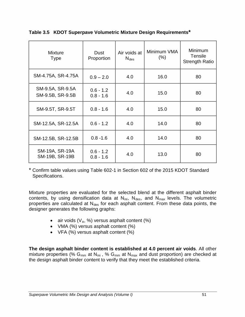
Superpave Volumetric Mix Design and Analysis (Volume I) 51
Table 3.5 KDOT Superpave Volumetric Mixture Design Requirements*
Mixture Type
Dust Proportion
Air voids at Ndes
Minimum VMA (%)
Minimum Tensile
Strength Ratio
SM-4.75A, SR-4.75A 0.9 – 2.0 4.0 16.0 80
SM-9.5A, SR-9.5A SM-9.5B, SR-9.5B
0.6 - 1.2 0.8 - 1.6 4.0 15.0 80
SM-9.5T, SR-9.5T 0.8 - 1.6 4.0 15.0 80
SM-12.5A, SR-12.5A 0.6 - 1.2 4.0 14.0 80
SM-12.5B, SR-12.5B 0.8 -1.6 4.0 14.0 80
SM-19A, SR-19A SM-19B, SR-19B
0.6 - 1.2 0.8 - 1.6 4.0 13.0 80
* Confirm table values using Table 602-1 in Section 602 of the 2015 KDOT StandardSpecifications.
Mixture properties are evaluated for the selected blend at the different asphalt binder contents, by using densification data at Nini, Ndes, and Nmax levels. The volumetric properties are calculated at Ndes for each asphalt content. From these data points, the designer generates the following graphs:
• air voids (Va, %) versus asphalt content (%)• VMA (%) versus asphalt content (%)• VFA (%) versus asphalt content (%)
The design asphalt binder content is established at 4.0 percent air voids. All other mixture properties (% Gmm at Nini , % Gmm at Nmax and dust proportion) are checked at the design asphalt binder content to verify that they meet the established criteria.

Superpave Volumetric Mix Design and Analysis (Volume I) 52
Moisture Susceptibility
The final step in the Superpave volumetric mix design process is to evaluate the moisture susceptibility of the design mixture. This step is accomplished by performing the KT-56 test on the design aggregate blend at the design asphalt binder content. Specimens are compacted to 7 ± 0.5 percent air voids. Loose lab produced mixtures are aged for 2 hours at compaction temperature before compaction. One subset of three specimens is considered control specimens. The other subset of three specimens is conditioned. The conditioned specimens are subjected to partial vacuum saturation (70% to 80% of air voids) followed by a freeze cycle at -18ºC for a minimum of 16 hours. The final conditioning step is a hot water soak at 60ºC for 23 to 25 hours. All specimens are then placed in a 25°C water bath for 2 hours. The specimens are then removed from the bath and tested at a loading rate of 51 mm/minute. The peak loads are recorded. The tensile strength is computed using the following formula:
DtPSt ××
×=
π2000 (3.23)
where: St = tensile strength (kPa) P = maximum load (N) t = specimen thickness (mm) D = specimen diameter (mm) π = pi (constant value of 3.14)
Table 3.6 outlines the current test parameters in KT-56. Note that when a lime anti-stripping agent is used in the mixture, testing requirements may vary as outlined in KT-56. The moisture susceptibility is determined as a ratio of the average tensile strengthsof the conditioned subset to the average tensile strengths of the unconditioned subsetand is calculated as:
1
2
SSTSR = (3.24)
where: TSR = tensile strength ratio S1 = average tensile strength of unconditioned subset, and S2 = average tensile strength of conditioned subset.
When an anti-stripping agent is used, include the agent in all asphalt mixtures for the conditioned and unconditioned subsets. The Superpave criteria for the acceptable minimum tensile strength ratio is 0.8 (80 percent), minimum; this has been adopted by KDOT also.

Superpave Volumetric Mix Design and Analysis (Volume I) 53
Table 3.6 Test Parameters for Moisture-Susceptibility Test (KT-56)
Test Parameter Test Requirement
Loose mix Aging (lab prepared mix only) 2 hrs ± 5 min at compaction temperature
Theoretical Maximum Specific Gravity KT-39
Air Voids of Compacted Specimens 7 ± 0.5 (6.5 to 7.5%)
Prior to, or after, Compaction Aging1 24 + 1 Hours
Sample Grouping Average air voids of the two subsets should be approximately equal
Vacuum Saturation 70 to 80% of air voids
Swell Determination None (however, record data per 7.3.8)
Freeze Minimum 16 hrs at -18 ± 5oC
Hot Water Soak 24 ± 1 hrs at 60 ± 1oC
Recondition for Test Temperature 2 hrs ± 10 minutes at 25 ± 0.5oC
Strength Property Indirect tensile strength
Loading Rate 51 mm/min at 25 ± 0.5oC
Precision Statement None
Test Parameter Ratio of average indirect tensile strength of wet/conditioned specimens to that of dry/unconditioned specimens
1 Aging protocol of AASHTO T283 does not match the aging protocol of Superpave or KT-56.
Superpave Volumetric Mix Design and Analysis (Volume I) 54
CHAPTER IV
OVERVIEW OF SUPERPAVE VOLUMETRIC MIX DESIGN
Design Steps
There are four major steps in the testing and analysis process for the Superpave volumetric mix design:
1.) selection of materials (aggregates, binders, modifiers, etc.) 2.) selection of a design aggregate structure 3.) selection of a design asphalt binder content 4.) evaluation of moisture susceptibility of the design mixture
Selection of materials consists of determining the traffic and environmental factors for the paving project as a first step. From there, the performance grade (PG) of asphalt binder required for the project is selected. Aggregate requirements are determined based on traffic. Materials are selected based on their ability to meet or exceed the established criteria.
Selection of the design aggregate structure consists of determining the aggregate stockpile proportions and corresponding combined gradation of the mix design. The design aggregate structure, at the design asphalt binder content, should yield acceptable volumetric and compaction properties when compared to the mixture criteria (based on traffic and environmental conditions).
Selection of a design asphalt binder content consists of varying the amount of asphalt binder in the design aggregate structure to obtain acceptable volumetric and compaction properties when compared to the mixture criteria (based on traffic and environmental conditions). It is a verification of the results obtained from the previous step. This step also allows the determination of the changes in the volumetric and compaction properties with changes in the percentage of asphalt binder.
Evaluation of moisture susceptibility consists of testing the mixture at design asphalt content by KT-56 to determine if the mix will be susceptible to moisture damage.
A complete outline of the steps in the Superpave Volumetric Mix Design is shown below:

Superpave Volumetric Mix Design and Analysis (Volume I) 55
l. SELECTION OF MATERIALS
A. Selection of Asphalt Binder
1. Determine project weather conditions using weather database2. Select reliability3. Determine design temperatures4. Verify asphalt binder grade5. Establish temperature-viscosity relationship for lab mixing and
compaction
B. Selection of Aggregates
1. Consensus properties:
a. Combined gradationb. Coarse aggregate angularityc. Fine aggregate angularityd. Flat and elongated particlese. Clay content
2. Agency and Other properties:
a. Specific gravityb. Toughnessc. Soundnessd. Deleterious materialse. Other
C. Selection of Modifiers (if any)
II. SELECTION OF DESIGN AGGREGATE STRUCTURE
A. Establish Trial Blends
1. Develop three blends2. Evaluate combined aggregate properties
B. Compact Trial Blend Specimens
1. Establish trial asphalt binder content2. Establish trial blend specimen size3. Determine Nini, Ndes and Nmax4. Batch trial blend specimens5. Compact specimens and generate densification tables6. Determine mixture densities (Gmm and Gmb)

Superpave Volumetric Mix Design and Analysis (Volume I) 56
C. Evaluate Trial Blends
1. Determine %Gmm at Nini, Ndes and Nmax2. Determine % Air Voids and % VMA3. Estimate asphalt binder content to achieve 4% air voids4. Estimate mix properties at estimated asphalt binder content5. Determine dust proportion6. Compare mixture properties to criteria
D. Select Most Promising Design Aggregate Structure for Further Analysis
III. SELECTION OF DESIGN ASPHALT BINDER CONTENT
A. Compact Design Aggregate Structure Specimens at Multiple BinderContents
1. Batch design aggregate structure specimens2. Compact specimens and generate densification tables
B. Determine Mixture Properties versus Asphalt Binder Content
1. Determine %Gmm at Nini, Ndes and Nmax2. Determine % Air Voids and % VMA3. Determine dust proportion4. Graph mixture properties versus asphalt binder content
C. Select Design Asphalt Binder Content
1. Determine asphalt binder content at 4% air voids2. Determine mixture properties at selected asphalt binder content3. Compare mixture properties to criteria
IV. EVALUATION OF MOISTURE SUSCEPTIBILITY OF DESIGN ASPHALTMIXTURE
A. Test Design Asphalt Mixture as per KT-56

Superpave Volumetric Mix Design and Analysis (Volume I) 57
APPENDIX A
KDOT SUPERPAVE MIXTURE GRADATION REQUIREMENTS

Superpave Volumetric Mix Design and Analysis (Volume I) 58
Table A.1 19 mm NOMINAL MAXIMUM SIZE (KDOT)
Sieve, mm
SM-19A Mixes Control Points
(Percent Retained)
SM-19B Mixes Control Points
(Percent Retained) Minimum Maximum Minimum Maximum
25 0 0 0 0
19 0 10 0 10
12.5 10 (min) 10 (min)
9.5
4.75
2.36 51 65 65 77
1.18
0.600
0.300
0.150
0.075 92 98 92 98
Table A.2 12.5 mm NOMINAL MAXIMUM SIZE (KDOT)
Sieve, mm
SM-12.5A Mixes Control Points
(Percent Retained)
SM-12.5B Mixes Control Points
(Percent Retained) Minimum Maximum Minimum Maximum
19 0 0 0 0
12.5 0 10 0 10
9.5 10 (min) 10 (min)
4.75
2.36 42 61 61 72
1.18
0.600
0.300
0.150
0.075 90 98 90 98

Superpave Volumetric Mix Design and Analysis (Volume I) 59
Table A.3 9.5 mm NOMINAL MAXIMUM SIZE (KDOT)
Sieve, mm
SM-9.5A Mixes Control Points
(Percent Retained)
SM-9.5B & SM-9.5T Mixes Control Points
(Percent Retained) Minimum Maximum Minimum Maximum
12.5 0 0 0 0
9.5 0 10 0 10
4.75 10 (min) 10 (min)
2.36 33 53 53 68
1.18
0.600
0.300
0.150
0.075 90 98 90 98
Table A.4 4.75 mm NOMINAL MAXIMUM SIZE (KDOT)
Sieve, mm
SM-4.75A Mixes Control Points
(Percent Retained) Minimum Maximum
12.5 0 0
9.5 0 5
4.75 0 10
2.36
1.18 40 70
0.600
0.300
0.150
0.075 88 94

Superpave Volumetric Mix Design and Analysis (Volume I) 60
APPENDIX B
ADDITIONAL INFORMATION
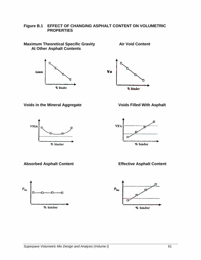
Superpave Volumetric Mix Design and Analysis (Volume I) 61
Figure B.1 EFFECT OF CHANGING ASPHALT CONTENT ON VOLUMETRIC PROPERTIES
Maximum Theoretical Specific Gravity Air Void Content At Other Asphalt Contents
Voids in the Mineral Aggregate Voids Filled With Asphalt
Absorbed Asphalt Content Effective Asphalt Content
SUPERPAVE VOLUMETRIC MIXTURE DESIGN AND ANALYSIS
HANDBOOK
Volume II Laboratory Manual
(2021)
Prepared by:
Mustaque Hossain, Ph.D., P.E. Department of Civil Engineering Kansas State University Manhattan, Kansas 66506
In cooperation with:
Glenn Fager, P.E. (retired) Rodney G. Maag, P.E. (retired) Kansas Department of Transportation Topeka, Kansas 66603
November 2020

COMPACTION OF SUPERPAVE HMA SAMPLES USING THE PINE SUPERPAVE GYRATORY
COMPACTOR
Superpave Laboratory Manual (Volume II) 1
SUPERPAVE HOT MIX ASPHALT GYRATORY COMPACTION
1.0 Objective: To compact hot mix asphalt (HMA) specimens for Superpave volumetric mixture design, analysis or moisture susceptibility determination.
2.0 Equipment:
2.1 Main: A Superpave gyratory compactor with a printer.
2.2 Ancillary:
(i)
(ii) (iii) (iv) (v) (vi)
Ovens, thermostatically-controlled, for heating aggregates, asphalt, and equipment. Large mechanical mixer, bowls, 12 liter capacity. Flat-bottom metal pans for heating aggregates and aging mix. Scoop for batching aggregates. Containers: gill-type tins, beakers, or pouring pots, for heating asphalt. Thermometers: armored, glass, or dial-type with metal stem, 10oC to 235oC, for determining temperature of aggregates, asphalt and asphalt mixtures.
(vii) Balances: 10-kg capacity, sensitive to 1 g, for weighing aggregates and asphalt;10-kg capacity, sensitive to 0.1 g, for weighing compacted specimens.
(viii) Large mixing spoon or small trowel.(ix) Large spatula.(x) High-temperature protective gloves for handling hot equipment.(xi) Paint, markers, or crayons, for identifying test specimens.(xii) Paper disks (100 mm or 150 mm) for compaction.(xiii) Fans for cooling compacted specimens.
3.0 Sample size
An aggregate mass of approximately 4,500 g is needed for one compacted specimen (150 mm diameter x nominal 115 mm height).
An aggregate mass of approximately 2,000 g is needed for the loose mixture sample used to determine the maximum theoretical specific gravity (Gmm).
Moisture Susceptibility testing using KT-56 requires a nominal specimen height of 95 mm and approximately 3,700 g of aggregate.
4.0 Approximate Working Temperature
Mixing temperature: Temperature corresponding to binder viscosity of 0.17 ± 0.02 Pa·s (or, approx. 143.5 ± 5.6oC)
Aggregate temperature: Mixing temperature + 15o C (or, approx. 158.5 ±5.6oC)
Asphalt temperature: Mixing temperature + 15o C (or, approx. 158.5 ± 5.6oC)
Compaction temperature: Temperature corresponding to binder viscosity of 0.28 ± 0.03 Pa·s (or, approx. 132.5 ± 5.6oC)
Short-term aging temperature: Compaction Temperature for 2 hours +/- 5 minutes. (Loose Mixture, lab mix only)

Superpave Laboratory Manual (Volume II) 2
5.0 Operation of the Gyratory Compactor:
The Superpave gyratory compactor to be used is a Pine Instrument Company Gyratory Compactor model AFGC125X or equivalent.
5.1 Control:
Always use automated control. Do not attempt to gyrate a mold without mix in it or without a consolidation pressure applied. Also, do not manually rotate the carriage with a mold unless a consolidation pressure is applied to a specimen in the mold.
Figure 5.1 shows the control screen of the Pine gyratory compactor model AFGC125X.
5.2 Setting:
The gyratory compactor control system allows for changing the compaction parameters. Use the SELECT key to choose the parameter to be changed (the selected value will flash). Use the ARROW keys to change the value to the desired setting. Only valid values will be accepted. Press the ENTER key to store the new value. The SELECT key will also store the new value and move to the next parameter. The OTHER OPTIONS on screen #2 will activate additional parameters that may be changed. The settings are saved in non-volatile memory so they require resetting when a change is needed. Normally no resetting would be required during a particular mixture design process. We will use the following mode for our class:
COMPACTION MODE: Compact to Number of Gyrations
Figure 5.1 Controls for a Pine Gyratory Compactor

Superpave Laboratory Manual (Volume II) 3
In Compact to Number of Gyrations mode of operation, the gyratory compactor will apply the set consolidation pressure, gyrate the specimen to the preset number of gyrations and then park automatically. The required settings are shown in Figure 5.2.
OTHER SETTINGS: No change will be required.
Caution: Do not press ROTATE, RAM and ANGLE keys for compaction.
Figure 5.2 Required Superpave gyratory compactor settings
0

Superpave Laboratory Manual (Volume II) 4
5.3 Mold Preparation
A clean mold assembly is essential for gyratory compaction. Follow the steps below in mold preparation for gyratory compaction:
(1) Clean and preheat the mold, mold base plate, and mold top plate. This is done at the high side of the compaction temperature range for the mix.
(2) Place the preheated mold in the compactor extruder bracket. Lubricate the bottom surface of the mold base plate lightly with a dry lubricant. Use the extruder to lift its ram and to support the mold base plate. Place a paper disk into the mold on top of the mold base plate. Note the correct orientation of the mold base flange is up (see Figure 5.3).
(3) Release the pressure of the extruder so that the mold base plate will be at the bottom of the mold.
(4) Lubricate the top surface of the mold top plate and the compaction chamber base with a dry lubricant. The top plate should have a medium coating of lubricant over the entire area except near the center where a heavy coat is required. The compaction chamber lubrication should be light, may not be needed after one test.
(5) Place the loose, preheated mixture into the mold. Use the extruder to lift the loose specimen so that its top is near flush with the top of the mold. Using a trowel make sure the top of the mixture is somewhat level. Place a paper disk, then the mold top plate, on top of the mixture. Note the correct orientation of the mold top plate is taper up (see Figure 5.3).
Figure 5.3 Gyratory Compactor Mold Assembly
(USE OILY RAG)
Superpave Laboratory Manual (Volume II) 5
(6) Release the extruder pump valve. Be certain there is no foreign debris on the mold flange. Wipe the mold flange on all surfaces with an oily rag. This lubrication will help prevent the rollers from skipping and grooving the flange. The mold is now ready to be placed into the compaction chamber.
5.4 Compaction Procedure
After the mold has been prepared as per section 5.3, follow the steps below to initiate the compaction procedure.
(1) Place the mold into the chamber and check that the mold is properly seated in the carriage by rotating it counter clockwise. The mold will spin easily when properly seated on all three sets of carriage rollers and they will fully engage the mold flange. Make sure that the anti-rotation cog is resting at the back of the chamber (12 o ‘clock).
(2) Once the input parameters on the control panel have been set and the mold is properly seated in the compaction chamber, close the chamber door. The machine ready light should now be illuminated. If the machine ready light is not lit at this point, the machine is not properly parked and will not initiate a test sequence.
(3) Make sure the printer is on and connected to the gyratory compactor.
(4) Make sure that all input parameters are correct before starting a test. Press the ENTER and START keys simultaneously to have the machine self-park (first test sequence only). Press START to initiate the compaction. Any other time after the test parameters have been used in a prior test sequence, just press START to initiate the compaction. The gyration number and specimen height will be printed in real time by the printer.
(5) The machine will automatically stop and park when the test has been completed. After the machine ready light is lit, remove the mold from the compaction chamber and allow to cool down sufficiently prior to extruding the specimen from the mold.
(6) Clean the compaction chamber to remove all debris.
Note: The STOP key may be used to temporarily pause the compaction process. The test may then be restarted or aborted. The EMERGENCY STOP button will stop the test and remove ram pressure. Opening the compaction chamber door will also pause the test. If the test stopped for any reason, the START key must be pressed to restart the machine. The test printout will indicate that the compaction process was paused prior to completion.
5.5 Maintenance
For routine maintenance, see Section 4.3 of the Pine AFGC125X Gyrator Compactor Operation Manual.
5.6 Calibration
Check the calibration as per recommendation in the Pine AFGC125X Gyrator Compactor Operation Manual.

Superpave Laboratory Manual (Volume II) 6
5.7 Applicable Standards
KT-58 Method for Preparing and Determining the Density of Hot Mix Asphalt (HMA) Specimens by Means of the Superpave Gyratory Compactor
KT-15 Bulk Specific Gravity and Unit Weight of Compacted Bituminous Mixtures
KT-39 Theoretical Maximum Specific Gravity of Bituminous Paving Mixtures
KT-56 Resistance of Compacted Asphalt Mixture to Moisture Induced Damage
Superpave Laboratory Manual (Volume II) 7
A SIMPLE OPERATIONAL MANUAL FOR THE ASPHALT BINDER IGNITION OVEN
(GILSON HM-378) STEP-BY-STEP PROCEDURE
A. INITIAL PHASE
1. Preheat the ignition furnace to 500°C (932°F) using the control panel as follows: a) If the desired program is known;
1) Press <enter> to bring the furnace to "idle". Press <enter> to display "_____".
2) Press <program> and <number of desired program>. 3) After the desired program has been selected and the furnace is "idle"
press <enter> <enter>. The furnace will switch to preheat.
b) If the desired program is unknown; 1) The furnace comes with one preset program. To review the program, from
"idle", press <enter> and <program review>. Customized Programs can be reviewed (starting from idle) by pressing <program> and the desired number, pressing <enter> then < stop>. Next press <enter> then <program review>.
2) After the desired program has been selected and the furnace is "idle" press <enter> <enter>. The furnace will switch to preheat.
c) Customizing Programs:**
1) From "idle" press <enter> to display "_____". Press <program> and a number where the new parameters will be stored.
Pressing the <enter> key causes the program to step through preset parameters. Continue pressing <enter> until the parameter to be changed is displayed. Simply enter the new parameter and press <enter>. Continue scrolling through the program until "idle" is displayed.
2) After the desired program has been selected and the furnace is "idle"
press <enter> <enter>. The furnace will switch to preheat.
2. Record the mass of the enclosure device (sample basket and catch pan) and any guards
supplied by the manufacturer.
3. Prepare the sample as described in Section 5 of Kansas Test Method KT-57. Place the sample in the sample enclosure device. Evenly distribute the loose mixture in the basket taking care to keep the material away from the edges of the basket. Use a spatula or trowel to level the specimen.
4. Record the mass of the sample and the sample enclosure device.
Superpave Laboratory Manual (Volume II) 8
**Note: The Bituminous Research Section's preliminary study has shown that a temperature of 500°C and a holding time of 40 minutes are sufficient to completely burn most samples weighing around 1,500 g.
B. IGNITION PHASE
1. Confirm the oven has been preheated.
2. Open the chamber door and place the loose mixture and sample enclosure device in thefurnace. Close the chamber door.
3. After the sample has been loaded and the door closed:
a) Press <continue> on the control panel to begin the ignition phase of the test
Note: DO NOT OPEN FURNACE DOOR after starting this test sequence. The asphalt vapors are highly flammable at 500°C (932°F) and may ignite if the door is opened.
Figure 1 below shows the ignition sequence.
C. END OF IGNITION PHASE
1) When the alarm begins beeping, the hold cycle is complete.a.) Press <stop>, the furnace will return to preheat mode. b.) If this is the last sample, go to C.2 and then shut down per E.1.
Note: This procedure is set up for the beginner. With experience the sequencing of samples will become apparent and a more efficient use of time will be obvious.
2) Remove the burnt material and allow it to cool enough to handle.
3) After the burnt material has cooled, weigh and record the mass of the sample and thesample enclosure device, and record the weight as the "After Wt."
4) Repeat steps above until a visual inspection indicates complete burn-off has beenaccomplished (KT-57, 10.10)
D. WASH GRADATION
1) Allow the material to cool to room temperature.2) After the material has cooled, run a washed gradation (KT-34).3) Calculations:
a.) 0% asphalt; "% retained" is calculated using the "Before Wt. (B1)" data. % Ret. = [(g Ret.)/B1] 100
b.) All other asphalt contents; "% Retained" is calculated using the "After Wt. Corrected (WA)" data.
% Ret. = [(g Ret.)/WA] 100

Superpave Laboratory Manual (Volume II) 9
Figure 1 Ignition Sequence (after Gilson Co., Inc.) Example: Pre-Heat Temperature set to 500°C Burn-Out Temperature set to 500°C Hold Time (Decoking) set at 40 minutes 1. Room Temperature 2. Pre-Heat temperature programmed by user 3. Open door to load sample; heat escapes 4. Close door and start test 5. Burn-out temperature programmed by the user (Could be the same as 2) 6. Peak Temperature as asphalt ignites and burns off (Varies) 7. Temperature returns to programmed burn out setting. Hold time (decoking) starts 8. End of Hold Time. Door can be opened, sample is removed, heat escapes 9. Door is closed 10. Furnace returns to programmed pre-heat temperature
20
Time
500
20 1
2 3
4
5
6
7
40 min
8
9
10
40 minutes
Superpave Laboratory Manual (Volume II) 10
E. SHUTTING DOWN 1) After the last sample has been finished, open the furnace door and push <stop> once to
bring it to the preheat mode. Press <stop> again to begin cooling down the furnace. The temperature on the control panel will blink indicating that the furnace is cooling. Once the temperature is below 300ºC, the power can be shut off.
F. SPECIAL NOTES 1) Samples containing asphalt content greater than 6.0%, on occasions, required an
additional 10 minute holding time. Therefore, two programs were developed to meet these needs. The primary program contained a 40 minute hold cycle and was used on all samples. The secondary program contained a 10 minute holding time and was used if the sample showed signs of incomplete burning.
2) Preliminary studies have also shown that the condition of the filter in the binder ignition
furnace influences the burning process and hence the test results. The filter may need to be replaced as often as every 2 - 4 tests depending on the asphalt content of the samples.
3) Because of the different intrinsic qualities of aggregate, there is a potential for aggregate
breakdown during the ignition process and sometimes a correction factor needs to be calculated (during the mix design phase) to correct for the loss of aggregate. Evaluate the aggregate breakdown by comparing the gradation analysis from the residual aggregates after the burn off to the gradation of an unburned, “blank” specimen (Refer to KT-57, 6.6)
G. SPECIAL CAUTIONS 1) Check that a filter is properly installed in the slot at the top of the furnace and the filter
has not clogged from previous tests to hinder air flow. Check filter before each test. 2) Be certain that the afterburner fan has been properly programmed at a fan-on
temperature setting of the afterburner. 3) Do not look through the small hole in the front of the chamber without wearing any eye
protection. 4) Never leave the furnace unattended near the end of burning.

Lab Data Page 1
APPENDIX A
DATA SHEETS FOR CALCULATIONS

Lab Data Page 2
Table 1 Project Environmental Conditions and Binder Grades
Weather Station & Reliability
Min. Pavement Temp (°C)
Max. Pavement Temp (°C)
Layer Type Binder Grade
Paving Location:
Latitude: Longitude:
20-year Design ESAL’s:______________
KDOT Mix Designation: ______________
Table 2 Aggregate Specific Gravities (KT-6)
Aggregate Bulk Specific Gravity Apparent Specific Gravity

Lab Data Page 3
Table 3 Gradation Criteria for __________ mm Nominal Maximum Size Mixture
Gradation Control Item Sieve Size, mm Maximum (%) Minimum (%)
Control Points
Table 4 Individual Aggregate Gradations (KT-2)
Sieve Size, mm
% Retained
Agg. 1 Agg. 2 Agg. 3 Agg. 4 Agg. 5

Lab Data Page 4
Table 5 Combined Gradation for Blend No. 1
(% Agg. 1= , % Agg. 2= , % Agg. 3= ,% Agg. 4= ,% Agg. 5= )
Sieve Size, mm
% Retained
Agg. 1 Agg. 2 Agg. 3 Agg. 4 Agg. 5 Blend

Lab Data Page 5
Table 6 Combined Gradation for Blend No. 2 (% Agg. 1= , % Agg. 2= , % Agg. 3= , % Agg. 4= , % Agg. 5= )
Sieve Size, mm
% Retained
Agg. 1 Agg. 2 Agg. 3 Agg. 4 Agg. 5 Blend

Lab Data Page 6
Table 7 Combined Gradation for Blend No. 3
(% Agg. 1= , % Agg. 2= , % Agg. 3= , % Agg. 4= , % Agg. 5= )
Sieve Size, mm
% Retained
Agg. 1 Agg. 2 Agg. 3 Agg. 4 Agg. 5 Blend

Lab Data Page 7
Table 8 Combined Gradation for Blend No. 4 (% Agg. 1= , % Agg. 2= , % Agg. 3= , % Agg. 4= , % Agg. 5= )
Sieve Size, mm
% Retained
Agg. 1 Agg. 2 Agg. 3 Agg. 4 Agg. 5 Blend

Lab Data Page 8
Table 9 Check Superpave Criteria for Gradation
Sieve Size, mm
% Retained
Blend 1 Blend 2 Blend 3 Blend 4 Superpave Control Points

Lab Data Page 9
Table 10 Check Aggregate Blend Properties
Property Criteria* Blend 1 Blend 2 Blend 3 Blend 4
Coarse Agg. Angularity Fine Agg. Angularity
Thin/ Elongated
Particles (%) Sand Equivalent
Combined Gsb -
Combined Gsa -
* based on traffic classification (___________ESAL’s) and pavement layer position (________ mm frompavement surface)

Lab Data Page 10
Table 11 Computation of Initial Asphalt Content (Pbi) for Trial Mix and Gmm Samples
Parameter Blend 1 Blend 2 Blend 3 Blend 4
Gsb
Gsa
Gse
Pb (%) 5 5 5 5
Ps (%) 95 95 95 95
Gb
Va (%) 4 4 4 4
Sn (mm)
Vbe
Vba
Ws
Pbi (%)

Lab Data Page 11
Table 12 Estimation of Aggregate and Asphalt Quantities for Sample Compaction and Theoretical Maximum Specific Gravity Determination Aggregates for trial mix = 4,500 g Gmm mix sample =1,600 g
Aggregate Quantity (g) Asphalt Quantity (g)
Trial mix Blend 1
Blend 2
Blend 3
Blend 4
Gmm sample Blend 1
Blend 2
Blend 3
Blend 4

Lab Data Page 12
Table 13 Densification Data for Trial Blend 1
Specimen No._______ Specimen No._______
Average Gmm (measured) = AC Content (%) =
No. of Gyra-tions
Specimen No. 1 Specimen No. 2 Avg. %
Gmm (corr)
Ht., hx (mm) Cx
Gmb (corr.) % Gmm Ht., hx
(mm) Cx Gmb
(corr.) % Gmm
5
Nini=
10
20
30
40
50
60
Ndes=
90
100
110
Nmax=
Gmb (measured) = hfinal (at Nmax) =
Gmb (measured) = hfinal (at Nmax) =
Note: Cx = hfinal / hx
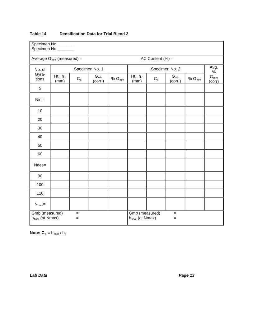
Lab Data Page 13
Table 14 Densification Data for Trial Blend 2 Specimen No._______ Specimen No._______
Average Gmm (measured) = AC Content (%) =
No. of Gyra-tions
Specimen No. 1 Specimen No. 2 Avg. %
Gmm (corr)
Ht., hx (mm) Cx
Gmb (corr.) % Gmm Ht., hx
(mm) Cx Gmb
(corr.) % Gmm
5
Nini=
10
20
30
40
50
60
Ndes=
90
100
110
Nmax=
Gmb (measured) = hfinal (at Nmax) =
Gmb (measured) = hfinal (at Nmax) =
Note: Cx = hfinal / hx

Lab Data Page 14
Table 15 Densification Data for Trial Blend 3
Specimen No._______ Specimen No._______
Average Gmm (measured) = AC Content (%) =
No. of Gyra-tions
Specimen No. 1 Specimen No. 2 Avg. %
Gmm (corr)
Ht., hx (mm) Cx
Gmb(corr.) % Gmm Ht., hx
(mm) Cx Gmb
(corr.) % Gmm
5
Nini=
10
20
30
40
50
60
Ndes=
90
100
110
Nmax=
Gmb (measured) = hfinal (at Nmax) =
Gmb (measured) = hfinal (at Nmax) =
Note: Cx = hfinal / hx

Lab Data Page 15
Table 16 Densification Data for Trial Blend 4
Specimen No._______ Specimen No._______
Average Gmm (measured) = AC Content (%) =
No. of Gyra-tions
Specimen No. 1 Specimen No. 2 Avg. %
Gmm (corr)
Ht., hx (mm) Cx
Gmb(corr.) % Gmm Ht., hx
(mm) Cx Gmb
(corr.) % Gmm
5
Nini=
10
20
30
40
50
60
Ndes=
90
100
110
Nmax=
Gmb (measured) = hfinal (at Nmax) =
Gmb (measured) = hfinal (at Nmax) =
Note: Cx = hfinal / hx

Lab Data Page 16
Table 17 Bulk Specific Gravity of Compacted Mixture (Gmb) (KT-15, Procedure III)
Specimen ID
Dry Mass in Air, g (A)
Mass in Water, g (C)
SSD Mass in Air, g (B)
Gmb = (A) / (B - C)
Table 18 Theoretical Maximum Specific Gravity (Gmm) of Loose Mixture (KT-39)
Sample No.
Mass of Flask, g (a)
Mass of Sample + Flask in Air, g (b)
Mass of Sample + Flask after 10 min. immersion in water, g (e)
Temperature of Bath, Sample and Flask after 10 min.
Mass of Flask in Water, g (d) (Measured or determined from calibration chart) Maximum Sp. Gr. of Mix, Gmm = (A) / (A - C)
A = (b - a) C = (e - d)

Lab Data Page 17
Table 19 Summary Properties of Trial Blends
Blend Initial %AC %Gmm at Nini=
%Gmm at Ndes=
%Gmm at Nmax=
% Air Voids % VMA
Table 20 Compute and Check Estimated Mixture Volumetric Properties @ Ndesign @ 4% Air Voids
Blend Initial %AC Est. %AC Est. % VMA Est. % VFA
Criteria - -
Table 21 Compute and Check Estimated Other Mixture Properties @ Ndesign @ 4% Air Voids
Blend Est. % Gmm @ Nini Est. % Gmm @Nmax Est. Dust Proportion
Criteria < 98%
Comments:___________________________________________________________
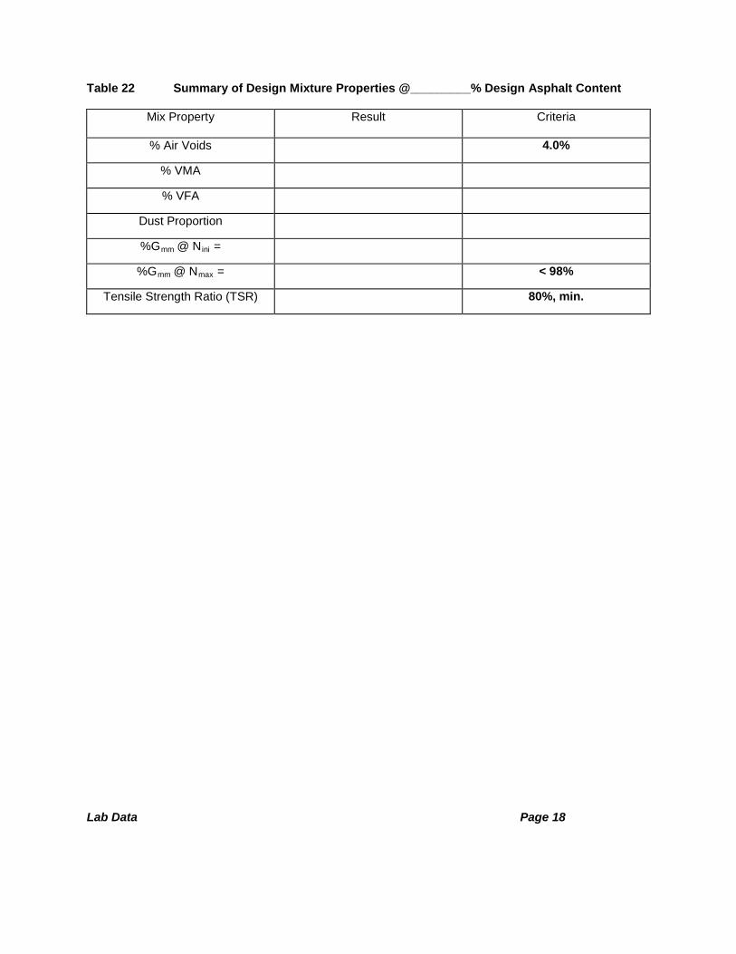
Lab Data Page 18
Table 22 Summary of Design Mixture Properties @_________% Design Asphalt Content
Mix Property Result Criteria
% Air Voids 4.0%
% VMA
% VFA
Dust Proportion
%Gmm @ Nini =
%Gmm @ Nmax = < 98%
Tensile Strength Ratio (TSR) 80%, min.
SUPERPAVE VOLUMETRIC MIXTURE DESIGN AND ANALYSIS
HANDBOOK
Volume III Laboratory Study Manual
(2021)
Developed by:
&
November 2020
Superpave Laboratory Study Manual (Volume III) 1
Compiled by:
Mustaque Hossain, Ph.D., P.E. Department of Civil Engineering Kansas State University Manhattan, Kansas 66506
and
Glenn Fager, P.E. (retired) Rodney G. Maag, P.E. (retired) Kansas Department of Transportation Topeka, Kansas 66603

Superpave Laboratory Study Manual (Volume III) 2
Table of Contents
KT-58 / AASHTO T312, Method for Preparing and Determining the Density of HotMix Asphalt (HMA) Specimens by Means of the Superpave GyratoryCompactor............................................................................................................................4
KT-15 / AASHTO T166, Bulk Specific Gravity and Unit Weight of CompactedAsphalt Mixtures................................................................................................................18
KT-39 / AASHTO T209, Theoretical Maximum Specific Gravity of Asphalt PavingMixtures.............................................................................................................................25
KT-57 / AASHTO T308, Determining the Asphalt Content and Gradation of HotMix Asphalt Concrete by the Ignition Method..................................................................33
KT-56 / AASHTO T283, Resistance of Compacted Asphalt Mixture to MoistureInduced Damage................................................................................................................42
Answers to Review Questions...........................................................................................52
Topic Page

Superpave Laboratory Study Manual (Volume III) 3
Preface
This study manual has been developed by heavily drawing from the M-TRAC training manual developed under the sponsorship of the Federal Highway Administration (FHWA). The M-TRAC manual was a part of a multi-regional effort to assist states with meeting the requirements of the Code of Federal Regulations, Part 637, for “qualified” personnel to perform material sampling and testing for quality control and quality acceptance (QC/QA). The ultimate goal of the group was also to promote reciprocity of this “qualification” across state lines. The development team members were Tom Deddens, formerly with the Asphalt Institute, John Hinrichsen, Asphalt Technician of the Iowa Department of Transportation, and Rebecca McDaniel, Technical Director of the North Central Superpave Center at Purdue University. The authors of this compilation acknowledge and appreciate this pioneering effort to have uniformity in training for bituminous material sampling and testing.
This study manual is intended to give an introduction to the tests that will be taught in the Superpave Field Technician (SF) Training classes at Kansas State University. The Kansas test methods are listed in the “Table of Contents” for this volume. References to other standards are listed on the first page of each test method. Knowledge of certain methods and tests is necessary before proceeding to other standard tests.
Training participants are expected to use the mathematical rounding rules recommended by KDOT in performing calculations for qualification testing.

Superpave Laboratory Study Manual (Volume III) 4
METHOD FOR PREPARING AND DETERMINING THE DENSITY OF HOT MIX ASPHALT (HMA) SPECIMENS BY MEANS OF THE SUPERPAVE
GYRATORY COMPACTOR
(Kansas Test Method KT-58 / AASHTO T312)

Superpave Laboratory Study Manual (Volume III) 5
NOTE
This discussion and KT-58 refer to the following KT Methods:
* KT-6/AASHTO T84 & 85, SpecificGravity and Absorption of Aggregate
* KT-15/AASHTO T166, Bulk SpecificGravity and Unit Weight of CompactedAsphalt Mixtures
* KT-25/AASHTO T168, StandardMethod of Test for SamplingBituminous Paving Mixtures
* KT-39/AASHTO T209, TheoreticalMaximum Specific Gravity of AsphaltPaving Mixtures
* KT-56/AASHTO T283, Resistance ofCompacted Asphalt Mixture to MoistureInduced Damage

Superpave Laboratory Study Manual (Volume III) 6
GLOSSARY
Cx= Correction factor for specific gravity after “x” number of gyrations (Cx = hfinal / hx)
hx = Height after "x" number of gyrations
hfinal= Height after final/maximum number of gyrations
Corrected %Gmm = the density of a specimen determined at x number of gyrations and expressed as a percentage of the maximum theoretical specific gravity of the mixture, corrected for the fact that it has been determined based on the bulk density of the Superpave gyratory specimen compacted to the maximum number of gyrations.
N-initial (Nini ) = the initial number of gyrations, a relatively low number of gyrations based onthe design traffic volume, and used to analyze the early densification properties of the Superpavemix during construction.
N-design (Ndes ) = the design number of gyrations, also based on the design traffic level, andused in the design of Superpave mixture.
N-maximum (Nmax ) = the maximum number of gyrations applied to a specimen, based on thedesign traffic volume, and used to assess the densification properties of the Superpave mixtureafter many years in service.

Superpave Laboratory Study Manual (Volume III) 7
Compacted samples of the Superpave mix are used to determine the volumetric and mechanical properties during the mix design phase and for quality control/quality assurance during construction. These volumetric properties are then evaluated to select a mix design or to control the mixture quality during production. The specimens produced with the Superpave gyratory compactor very closely simulate the density, aggregate orientation and structural characteristics of the mixture on the actual roadway.
The gyratory compactor is used to prepare specimens for later analysis of the volumetric properties of the mixture, evaluation of mixture densification properties, evaluation of moisture sensitivity, field quality control and/or other testing purposes.
This text will explain the method of compacting samples of the Superpave mix using the Superpave gyratory compactor and determining their percent compaction. This method may be used with laboratory-prepared specimens, as in the mix design process, or with plant-mixed material during construction.
Common Testing Errors
• Not placing a paper protection disk at the bottom or on the top of the specimen.
• Not placing the top plate.
• Not preheating the mold and base plate.
• Not charging the mold with mix quickly, in one lift without spading or rodding.
• Not compacting the mixture at proper temperature.
• Not removing the paper disks while the specimen is still warm.
PREPARING AND DETERMINING THE DENSITY OF HMA SPECIMENS BY MEANS OF THE SUPERPAVE GYRATORY
COMPACTOR

Superpave Laboratory Study Manual (Volume III) 8
TEST METHODOLOGY
Apparatus
• Superpave Gyratory Compactor: The compactor may also include a printer or a computerand software for collecting and printing the data. (Pine AFGC125X referenced in thismanual)
• Specimen molds, and top and bottom plates• Thermometer• Balance readable to 0.1 g• Oven, thermostatically controlled with a range from 50 to 260oC with ± 3oC tolerance• Calibration equipment recommended by compactor manufacturer• Safety equipment: insulated gloves, long sleeves, etc.• Miscellaneous equipment: paper disks, lubricating materials recommended by compactor
manufacturer, scoop or trowel for moving mixture, funnel or other device for ease ofloading mixture into mold (optional).
Calibration
The means of calibrating the gyratory compactor vary with different manufacturers. Refer to the operation manual of the particular brand and model of gyratory available for use. Calibration of the following items should be verified at the noted intervals of the Contractor’s Quality Control Plan approved by the State or according to manufacturers’ recommendations (as applicable):
Item Tolerance Calibration/Verification Interval (months)
Height Record to nearest 0.1 mm, Compact to 115 ± 5 mm 12*
Angle (Internal) 1.16° ± 0.02° 12*
Pressure 600 ± 18 kPa 12*
Speed of Rotation 30.0 ± 0.5 gyrations per minute
12*
*6 for large Pine Models AFGC125X
Mold and plate dimensions, hardness and smoothness should also be verified. Oven temperature should be verified; oven must be capable of maintaining the temperature as required for short-term aging according to KT-58 section 4.2.

Superpave Laboratory Study Manual (Volume III) 9
Sample Preparation
Samples for compaction in the gyratory may be obtained in one of two ways; mixture may be prepared in the laboratory or plant-mixed material may be obtained from the roadway behind the paver.
For determination of volumetric properties for mix design or quality control, a finished specimen height of 115 ± 5 mm is required. When compacting specimens for testing in KT-56, Resistance of Compacted Bituminous Mixture to Moisture Induced Damage, a specimen height of 95 ± 5 mm is required. In this case, the batch mass must be varied to provide the desired specimen height at a specified air void content; samples are then compacted to the specified height rather than for a fixed number of gyrations (See KT-56 for more details.)
Laboratory Prepared Materials
Preparing samples of mixture in the laboratory requires batching out the aggregates, mixing proper amount of asphalt binder, conditioning the prepared mixture, heating the mixture to compaction temperature, and compacting the specimen. The steps involved in preparing the mixture in the laboratory are as follows:
1. Weigh out appropriate amounts of the required aggregate size fractions and combine in a bowlto the proper batch mass. Typically, a batch mass of 4,500 grams of aggregate will provideenough material for a finished specimen height of 115 ± 5 mm.
2. Heat the asphalt binder and the combined aggregate in an oven to the appropriate mixingtemperature for the binder to be used. This temperature is determined from an equi-viscoustemperature chart or will be provided by the binder supplier. The appropriate temperature rangefor mixing is defined as the range of temperatures that produces a viscosity of 0.17 ± 0.02 Pa·sfor the unaged binder. This ensures that the binder is fluid enough to coat the aggregate particles.Some modified binders do not follow these temperature-viscosity relationships; themanufacturer’s recommendations should be followed.
3. The heated aggregate should be placed in the mixing bowl and thoroughly dry mixed. Make acrater at the center of the aggregate in the bowl and weigh in the required amount of asphaltbinder. Begin mixing immediately.
4. A mechanical mixer is recommended for preparing laboratory mixtures. Mixing shouldcontinue until the asphalt binder is uniformly distributed over the aggregate particles.
5. Determine the proper compaction temperature range for the asphalt binder used. This isdefined as the range of temperatures that yields a binder viscosity of approximately 0.28 ± 0.03Pa·s. Modified binders may not conform to these mixing and compaction temperatures, so themanufacturer’s recommendations should be followed.
6. After mixing, spread the loose mixture in a flat, shallow pan and short term age it as follows:

Superpave Laboratory Study Manual (Volume III) 10
Place the mixture on a baking pan and spread it to an even thickness. Place the mixture and pan in the aging oven set at compaction temperature 2 hours ± 5 minutes at the specified mixture’s compaction temperature. The compaction temperature varies depending on the grade of binder used and can be determined from state specifications or the binder supplier’s recommendations. (Note: The compaction temperature range of an HMA mixture is defined as the range of temperatures where the unaged asphalt binder has a kinematic viscosity of 280 ± 30 mm2/S (approximately 0.28 ± 0.03 Pa·s) measured in accordance with ASTM D4402. The target compaction temperature is generally the mid-point of this range. When using modified asphalts, the binder manufacturer’s recommendation for compaction temperature should be considered.)
Stir mixture every 60 ± 5 minutes to maintain uniform aging.
After 2 hours ± 5 minutes, remove the mixture from the oven. The aged mixture is now ready for further tests.
7. Place the mold and base plates in an oven permitting the pieces to reach the establishedcompaction temperature prior to the estimated beginning of the compaction process.
Plant-Mixed Materials
When plant-mixed materials are sampled from the roadway behind the paver (KT-25), no aging or conditioning is required. The mixture must be brought to the proper compaction temperature then compacted and analyzed if the temperature of the mixture has dropped below the compaction temperature. Place the material in an oven at the compaction temperature and bring the mixture to the proper temperature by careful, uniform heating. The mix should be stirred periodically to help assure uniform heating. In general, the shortest heating time that will bring the mixture to the compaction temperature is preferred. Avoid over-heating the mix. When the compaction temperature has been reached, proceed with specimen compaction as outlined below.
Compaction Procedure
Once the mixture sample has reached the proper compaction temperature, it is compacted in the Superpave gyratory compactor. For most purposes, the finished specimens will be used to calculate volumetric properties and the specimens will be compacted to a fixed number of gyrations. When preparing specimens for testing under KT-56, Resistance of Compacted Bituminous Mixture to Moisture Induced Damage, specimens may be compacted to a fixed height to produce a specified air void content.
The procedure to compact to a fixed number of gyrations is as follows:
1. Ensure that the gyratory compactor has been turned on and allowed to warm up for the timerecommended by the manufacturer. Verify all settings for angle, pressure and number ofgyrations.
Superpave Laboratory Study Manual (Volume III) 11
2. When the compaction temperature has been reached, remove the mold and base plate from theoven. Put the base plate in position in the mold and place a paper disk in the bottom of the mold.If necessary apply some lubricant to the top and base plates.
3. Thoroughly mix the material. Charge the mixture into the mold in one lift. A funnel or otherdevice may be used to place the mixture into the mold. Avoid segregating the mix in the mold,but work quickly so that the mixture does not cool excessively during loading. Verify thetemperature of the material. The temperature of the material is to be at the midpoint of theestablished compaction temperature ± 1.5°C for the specified PG asphalt. Level the mix in themold, place a paper disk on top, and put the top plate on top of the paper disk.
4. Place the mold in the Superpave gyratory as per manufacturer’s recommendations (Somegyratories allow charging the mold with mix after the mold has been positioned in thecompactor). Lubricate the mold or gyratory parts as recommended by the manufacturer.
5. Apply the load to the mixture in the mold according to manufacturer’s recommendations. Thepressure applied should be 600 ± 18 kPa.
6. Apply the gyratory internal angle of 1.16°± 0.02° to the specimen.
7. Input the desired number of gyrations (Nmax) to apply on the Superpave compactor controlpad. Start the compaction process and compact to the required number of gyrations. The numberof gyrations to apply is determined from the Table 1 and is based on the expected design trafficvolume in Equivalent Single Axle Loads (ESALs) over a 20-year design life. This information isprovided in the special provisions for the project. Compact to the desired number of gyrations.Volumetric and densification properties are determined at Nini and Ndes as well as Nmax, asdescribed later.
8. The gyratory compactor will stop automatically when the specified Nmax has been reached.Remove the angle from the specimen and raise the loading ram if needed (this is doneautomatically on some compactor models).
9. Remove the mold from the compactor, if required, and extrude the specimen from the mold.Take care not to distort the specimen when removing it from the mold. A cooling period of 5 to10 minutes may be necessary with some mixtures; a fan may help speed up the cooling process.Remove the paper disks while the specimen is still warm to avoid excessive sticking.

Superpave Laboratory Study Manual (Volume III) 12
Table 1 Gyratory Compactive Effort
20-year Design ESALs(millions)
Compaction Parameter
Nini Ndes Nmax
< 0.3 *** 6 50 75
0.3 to <3 *** 7 75 115
3 to <30 8 100 160
> 30 9 125 205
Shoulder * A 6 50 75
B ** ** **
(*) At the contractor’s option A or B may be used (**) Use traveled way design properties (***) Some projects may use Nini = 6 & Ndes = 60 with no Nmax requirement
Density Procedure
When compacting specimens for determination of volumetric properties for mix design or quality control/quality assurance, it is necessary to know the specimen height and bulk specific gravity and mixture maximum theoretical specific gravity. This requires following additional steps:
1. Prepare a loose sample of the same mixtures and determine the maximum theoretical specificgravity (Gmm) in accordance with KT-39 or AASHTO T209, Maximum Specific Gravity ofBituminous Paving Mixtures.
2. Compact a specimen using a Superpave Gyratory compactor and the maximum number ofgyrations (Nmax) for the project. Record the height of the specimen to the nearest 0.1 mm aftereach gyration.
3. Measure and record the mass of the compacted specimen to the nearest 0.1 g. Determine thebulk specific gravity (Gmb ) of the compacted specimen in accordance with KT-15, Procedure IIIor AASHTO T166, Method A, Bulk Specific Gravity of Compacted Bituminous Paving MixturesUsing Saturated Surface Dry Specimens.

Superpave Laboratory Study Manual (Volume III) 13
Calculations
Using the measured bulk specific gravity of the final compacted specimen and the measured maximum specific gravity of a loose sample of the mixture, and knowing the height of the specimen at different numbers of gyrations, it is possible to calculate the corrected %Gmm of the specimen. The corrected %Gmm at any number of gyrations is expressed as a percentage of the maximum theoretical specific gravity (Gmm) for the mix. This allows a determination of the air void content of the specimen at any number of gyrations as (100 - %Gmm).
The %Gmm at any number of gyrations is calculated as follows:
1. Calculate the correction factor (Cx ) for specific gravity after “x” number of gyrations as:
Cx = hfinal / h x
where: hx = height of the specimen (in mm) during compaction at x gyrations, and hfinal = height of the specimen (in mm) after Nmax gyrations.
2. The corrected bulk specific gravity Gmb (corrected) of a specimen at any level (x) of gyrationcan be computed as:
where: Gmb (measured) is the bulk specific gravity of the extruded specimen (determined using KT-15, Procedure III/AASHTO T 166, Method A).
3. The % Gmm at any gyration level is then calculated as:
[Gmb (corrected)/ Gmm ] * 100,
where: Gmm is the maximum theoretical specific gravity of the mixture (determined according to KT-39/AASHTO 209)
4. Report the %Gmm to the nearest 0.1 percent and the average %Gmm value for the twocompanion specimens is typically used.
[Note: the relative density is described as “corrected” because of the calculation process. The volumetric properties of the compacted specimen at any compaction level are calculated based on the bulk specific gravity (Gmb) of the specimen measured at Nmax according to KT-15, Procedure III/AASHTO T166, Method A. To compute %Gmm at any gyration level, the “corrected” or “back calculated” bulk specific gravity needs to be determined at that level from the measured bulk specific gravity (Gmb) of the specimen measured at Nmax. The correction factor in the form of “height ratio” is used to back calculate the “corrected” bulk specific gravity at any level of gyration. The calculations are as described above and in the following example.]
Gmb (corrected) = Gmb (measured) x hfinal / hx

Superpave Laboratory Study Manual (Volume III) 14
Example: Given: Gmb , measured bulk specific gravity = 2.369 Gmm , maximum theoretical specific gravity = 2.403 hfinal , height of specimen at Nmax = 117.5 mm Calculate % Gmm at Nini = 8 gyrations, h8 = 135.4 mm Ndes = 100 gyrations, h100 = 119.4 mm Nmax = 160 gyrations, h160 = 117.5 mm
At x = 8 gyrations level:
C8 = (117.5 mm/135.4 mm) = 0.868 Gmb (corrected) = 2.369 x C8 = 2.369 x 0.868 = 2.056 % Gmm = 2.056/2.403 x 100 = 85.6% At x = 100 gyrations level: C100 = (117.5 mm/119.4 mm) = 0.984 Gmb (corrected) = 2.369 x C100 = 2.369 x 0.984 = 2.331 % Gmm = (2.331/2.403) x100 = 97.0% At x = 160 gyrations level: C160 = (117.5 mm/117.5 mm) = 1.0 Gmb (corrected) = 2.369 x C160 = 2.369 x 1.0 = 2.369 % Gmm = (2.369/2.403) x 100 = 98.6%
% Air Voids at Ndes = 100 - %Gmm @ Ndes (x= 100) = 100 - 97.0 = 3%
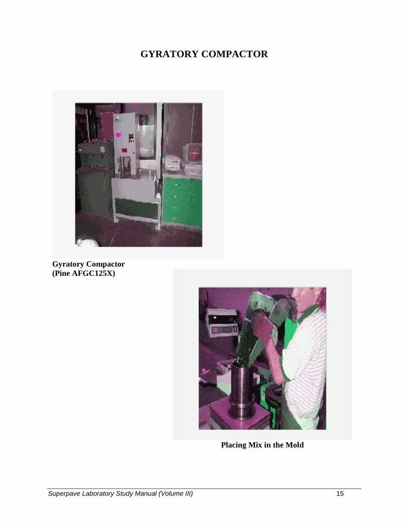
Superpave Laboratory Study Manual (Volume III) 15
GYRATORY COMPACTOR
Gyratory Compactor (Pine AFGC125X)
Placing Mix in the Mold

Superpave Laboratory Study Manual (Volume III) 16
Placing Mold into the Compactor
Mold in Compactor Ready to Test

Superpave Laboratory Study Manual (Volume III) 17
Review Questions
1) The required sample height for the design mix in the gyratory compaction is ________ ±
________ mm.
2) The vertical pressure applied by the gyratory compactor is ________ ± _________ kPa.
3) The internal angle of gyration is _______ ± _________o.
4) The number of revolutions per minute is ___________________.
5) The compaction temperature depends on the type of PG binder? ______________(Yes or No)
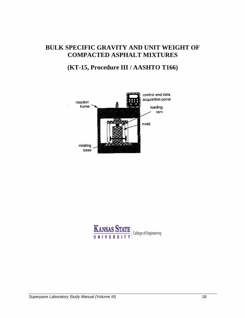
Superpave Laboratory Study Manual (Volume III) 18
BULK SPECIFIC GRAVITY AND UNIT WEIGHT OF COMPACTED ASPHALT MIXTURES
(KT-15, Procedure III / AASHTO T166)

Superpave Laboratory Study Manual (Volume III) 19
NOTE
This discussion and KT-15 refer to the following KT Methods:
* KT-25/AASHTO T168, Standard
Method of Test for Sampling Bituminous Paving Mixtures
* KT-58/AASHTO T312, Method For Preparing and Determining the Density
of Hot Mix Asphalt (HMA) Specimens by Means of the Superpave Gyratory Compactor
Superpave Laboratory Study Manual (Volume III) 20
GLOSSARY
Specific gravity: the ratio of the mass in air of a given volume of material to the mass in air of an equal volume of water. Saturated surface dry (SSD): the condition of a material when it has absorbed as much water as it can during a specified time period in its water permeable pores but the outside of the material has no free water.

Superpave Laboratory Study Manual (Volume III) 21
The compaction of a Superpave mixture, both in the field and in the laboratory, is an important characteristic to be determined for mixture quality control. The bulk specific gravity (Gmb) of compacted specimens can be determined on pavement cores or laboratory compacted specimens. The bulk specific gravity of compacted bituminous mixtures, using a saturated surface-dry specimen, is used to determine air voids (Va), and may be used for comparison between roadway compaction tests and laboratory compacted specimens. The Gmb is determined by measuring the volume of the specimen by displacement when submerged in water. Measure the specimen dry mass, mass of the specimen submerged in water, and the SSD mass to determine Gmb. The submerged mass is subtracted from the SSD mass to determine the mass of an equal volume of displaced water. Dividing the dry mass of the specimen by the mass of an equal volume of the water as the specimen yields the Gmb. KT-15, Procedure III is applicable when the water absorption is less than 2.0 %. Common Testing Errors Submerged specimen touches the side of the water container. Water temperature is not 25˚± 1˚C (77˚± 2˚F).
Specimens with high voids (>10%) may absorb excess water.
Dirty water used.
Specimens not cooled to 25˚± 3˚C (77˚± 5˚F) or less.
BULK SPECIFIC GRAVITY AND UNIT WEIGHT OF COMPACTED ASPHALT MIXTURES

Superpave Laboratory Study Manual (Volume III) 22
TEST METHODOLOGY
Apparatus
Balance (accurate to 0.1 gram).
Oven for heating specimen
Submersion basket
Water bath
Damp towel
Sample Preparation (Field mix)
The sample should be obtained using KT-25/AASHTO T168. The mixture should then be compacted for testing using KT-58/AASHTO T312.
Testing Procedure
Cool the specimen to room temperature at 25 ± 3˚C (77 ± 5˚F) and record the dry mass to the nearest 0.1 g. The specimen is then immersed in a 25 ± 1˚C (77 ± 2˚F) water bath and saturated at 4 ± 1 minutes. Determine the mass in water to the nearest 0.1 g. Remove the immersed saturated specimen from the water bath and damp dry with a damp absorbent cloth as quickly as possible. The specimen is then weighed. Any water that seeps from the specimen during the weighing operation is considered as part of the saturated specimen.
Weighing Specimen in Air
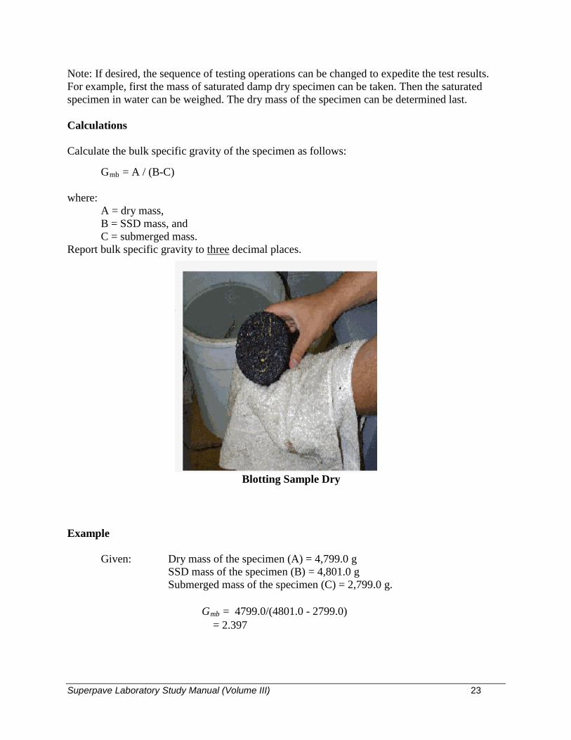
Superpave Laboratory Study Manual (Volume III) 23
Note: If desired, the sequence of testing operations can be changed to expedite the test results. For example, first the mass of saturated damp dry specimen can be taken. Then the saturated specimen in water can be weighed. The dry mass of the specimen can be determined last.
Calculations
Calculate the bulk specific gravity of the specimen as follows:
Gmb = A / (B-C)
where: A = dry mass, B = SSD mass, and C = submerged mass.
Report bulk specific gravity to three decimal places.
Example
Given: Dry mass of the specimen (A) = 4,799.0 g SSD mass of the specimen (B) = 4,801.0 g Submerged mass of the specimen (C) = 2,799.0 g.
Gmb = 4799.0/(4801.0 - 2799.0) = 2.397
Blotting Sample Dry

Superpave Laboratory Study Manual (Volume III) 24
1) In KT-15 test method, mass of dry sample in air is determined at _______ ± _________o C.
2) In KT-15 test method, Procedure III, the sample is immersed in water before weighing for
__________± _______ min.
3) In KT-15, the temperature of water bath is _______ ± _________ o C.
4) Percent water absorption for the specimen for test in KT-15 Procedure III should be less than
____________%.
5) If the dry mass of a Superpave gyratory plug is 4,440 g, the mass in water is 2,600 g and the
SSD mass is 4,490 g then the bulk specific gravity is ___________?
Review Questions

Superpave Laboratory Study Manual (Volume III) 25
THEORETICAL MAXIMUM SPECIFIC GRAVITY OF ASPHALT PAVING MIXTURES
(Kansas Test Method KT-39 / AASHTO T209)

Superpave Laboratory Study Manual (Volume III) 26
NOTE
This discussion and KT-39 refer to the following KT Method:
* KT-25/AASHTO T168, StandardMethod of Test for SamplingBituminous Paving Mixtures
* KT-58/AASHTO T312, Method ForPreparing and Determining the Densityof Hot Mix Asphalt (HMA) Specimensby Means of the Superpave GyratoryCompactor

Superpave Laboratory Study Manual (Volume III) 27
GLOSSARY
Specific gravity: the ratio of the mass in air of a given volume of material to the mass in air of an equal volume of water.
Pycnometer: a vessel of known volume used to measure the volume of a material placed in it by determining how much water is displaced.
Mercury Manometer: a tube sealed at one end and filled with mercury, which, when subjected to a vacuum, will register a comparison between the applied vacuum and the nearly total vacuum that exists in the sealed end. The degree of vacuum is expressed as absolute pressure or residual pressure, in mm. Smaller numbers (lower pressure) indicate more vacuum.
Digital Manometer: A digital, electronic manometer designed to read absolute pressure. The degree of vacuum is also expressed as absolute pressure or residual pressure, in mm.
Maximum Aggregate Size: one sieve size larger than the “nominal maximum aggregate size”. For reference, the “nominal maximum aggregate size” is one sieve size larger than the first sieve that retains more than 10 percent of the aggregate. (Note: This terminology and these definitions are used for Superpave mixtures and may not apply to other types of mixtures.)
Tare: setting the balance to zero with a mass on top (usually an empty container), so that when a sample is placed in the container it can be placed on the balance and only the sample mass will be displayed.
Superpave Laboratory Study Manual (Volume III) 28
The volumetric properties of compacted Superpave mixtures must be controlled during design and production in order to produce durable pavements. James Rice invented a test to measure the specific gravity of a loose mixture with all air removed. This specific gravity is known as the maximum specific gravity (Gmm ), and is the ratio of the mass of the loose sample to the mass of an equal volume of water at the standard temperature of 25o C (77o F). Gmm is used along with the bulk specific gravity (Gmb ) of the compacted mixture to determine air voids (Va). Gmm is also used in determining percent compaction achieved in the field. This text will explain the flask method for determining the maximum specific gravity. The flask method is the preferred test method due to lower variability. Common Testing Errors Not breaking up the sample completely.
Not maintaining 27 ± 3 mm of Hg absolute pressure which could be attributed to one of
the following: a. Air bubble in mercury manometer* b. Manometer not connected directly to pycnometer* c. Clogged or leaking vacuum lines d. Moisture or foreign material getting into the vacuum pump Not agitating the sample enough. Flask not staying suspended in the water; i.e., hitting the bottom of the water bath
Not checking water temperatures.
Uncoated particles or particles that rupture under vacuum which absorb water.
Overheating absorptive materials.
* during this training period only digital manometers will be used
THEORETICAL MAXIMUM SPECIFIC GRAVITY OF ASPHALT PAVING MIXTURES

Superpave Laboratory Study Manual (Volume III) 29
TEST METHODOLOGY - FLASK METHOD Apparatus
• Pycnometer or flask
• Thermometer
• Mercury/Digital Manometer
• Vibrating Table
• Scale
• Vacuum pump, tubing and connectors Sample Preparation
• If the sample is not tested soon after it has been sampled, it will cool down, and may need to be reheated in the oven before the Gmm test can be run. If necessary, heat the sample only enough to soften it so that separation is possible.
• Reduce the sample to the proper size, if necessary, by quartering or other suitable means
that will ensure a representative sample. See Table 2 below for the required sample size. Table 2 Required Sample Size
Maximum Aggregate Size Minimum Sample Size
25.0 mm (1 in.) 2,500 g 19.0 mm (3/4 in.) 2,000 g 12.5 mm (½ in.) 1,500 g 9.5 mm (3/8 in.) 1,000 g
4.75 mm (#4) 500 g
Pycnometer and Flask

Superpave Laboratory Study Manual (Volume III) 30
• Separate the particles of coarse aggregate. Break up any clumps of fine aggregate so thatno clump is larger than 6.3 mm (¼ in.). Stirring or spading the mixture as it cools willprevent clumps. If the clumps are difficult to break up, warming the mixture for a fewminutes will be helpful.
• Allow the mixture to cool to room temperature before proceeding with the test.
Calibration of Flask
• The mass of the flask is calibrated when immersed in water while the water is maintainedat 77 ± 2oF (25 ± 1oC). Record the mass to the nearest 0.1 g. This is mass “d” (lower case‘d’), for use with the weigh in water method.
Test Procedure
• Tare the flask on a scale and add the sample. Record the mass of the sample to the nearest0.1 gm. This mass is the dry sample mass in air “A”.
• Add enough water to completely cover the sample.
• Connect the flask to the vacuum system and remove the entrapped air. Maintain avacuum, as measured by a mercury/digital manometer, of 27 ± 3 mm absolute pressurefor 14 ± 0.5 minutes. Apply continuous agitation by a mechanical device to help releasethe air bubbles.
• After the 14-minute vacuum period is complete, slowly release the vacuum (not to exceed60 mm of Hg per second) and proceed with the following determination:
Stirring Sample and Breaking Clumps

Superpave Laboratory Study Manual (Volume III) 31
• Weighing in water: Suspend the flask and sample in the water bath and determine the mass after 10 ± 1 minute immersion. Verify that the temperature of the water bath is 77 ± 2 oF (25 ± 1 oC). Call this mass “e” (lower case ‘e’). Subtract the mass of the calibrated flask (d) from the mass of the flask and sample immersed in water (e) to determine the mass of the sample in water “C”.
Calculations Weighing in water: Maximum Specific Gravity (Gmm ) = A/(A-C) where: A = Mass of dry sample in air, g, and
C = Mass of water displaced by loose, airless mixture sample at 77 oF (25 oC). Report Maximum Specific Gravity (Gmm ) to three decimal places. Example Given: Mass of dry sample in air (A) = 1545.0 g Mass of water displaced by the sample (C) = 917.7 g Gmm = 1545.0 = 2.463 (1545.0 – 917.7)
Sample Under Vacuum

Superpave Laboratory Study Manual (Volume III) 32
1) The temperature of water bath in KT-39 is __________ ± ___________ oC .
2) After separation, lumps with fine aggregates in KT-39 will not be larger than _________ mm.
3) The vacuum applied to remove entrapped air in KT-39 is _________ ± __________ mm ofHg.
4) For under water weighing, in KT-39 the sample is suspended in water for _________ ±
___________ minute.
5) The sample size for a mix with 12.5 mm maximum aggregate size is ___________ g.
6) The KT-39 sample from behind the paver is obtained by ____________________________.(Splitting or Quartering)
7) The maximum specific gravity (Gmm) is reported to _______________ decimal places.
8) The KT-39 sample for the design mixture is aged in a preheated draft oven at compactiontemperature for ____________ hours.
Review Questions

Superpave Laboratory Study Manual (Volume III) 33
DETERMINING THE ASPHALT CONTENT AND GRADATION OF HOT MIX ASPHALT CONCRETE BY THE IGNITION
METHOD
(Kansas Test Method KT-57 / AASHTO T308)
Superpave Laboratory Study Manual (Volume III) 34
NOTE
This discussion and KT-57 refer to the following KT Methods:
* KT-1/AASHTO T2 & 248, SamplingAggregates
* KT-25/AASHTO T168, StandardMethod of Test for SamplingBituminous Paving Mixtures
* KT-26/AASHTO T40, SamplingAsphalt Materials
* KT-34/AASHTO T30, Sieve Analysisof Extracted Aggregate

Superpave Laboratory Study Manual (Volume III) 35
Ignition oven: A muffle furnace specifically designed for the purpose of burning off organic components from a material at high temperatures.
Correction factor: The difference between the actual and the measured asphalt content.
Sample basket: A sample container designed for use in the ignition oven which allows the heated air to move through the sample. Each oven manufacturer provides baskets designed for use in their oven.
Nominal Maximum Aggregate Size: One sieve size larger than the first sieve that retains more than 10 percent of the aggregates (Note: This terminology and definition is used for Superpave mixtures and may not apply to other types of mixtures.)
GLOSSARY

Superpave Laboratory Study Manual (Volume III) 36
Maintaining the proper asphalt content consistency in the Superpave paving mixture is a key factor in producing quality pavement. Various means of determining asphalt content, such as chemical extraction or nuclear gauges, have been used for many years. Newer technology has been perfected by the National Center for Asphalt Technology (NCAT). This process uses a very high temperature oven, commonly called a muffle furnace, to burn off the asphalt. By comparing the mass of the sample before and after the burn off, the asphalt content can be determined. Some aggregates tend to break down at the high temperatures used in the test, and, therefore, a correction factor for each mix may be needed to get accurate results. After the asphalt content has been determined, the aggregate that is left behind can be tested for gradation and other properties. (Note: Some aggregates have demonstrated significant breakdown at the high temperatures applied in this test and may produce erroneous gradation and specific gravity test results.) Although the technician may encounter very hot materials and must use proper precautions, this is the easiest and safest method available for determining asphalt content and providing clean aggregate for further testing. This test method is appropriate for both field labs conducting quality control tests and Agency labs performing independent assurance, verification and acceptance testing. Common Testing Errors Moisture in the sample.
Materials used for calibration were not the same as project materials.
Inaccurate asphalt content used for calibration.
Improper loading of sample baskets.
DETERMINING THE ASPHALT CONTENT AND GRADATION OF HOT MIX ASPHALT CONCRETE BY THE IGNITION METHOD
TEST METHODOLOGY
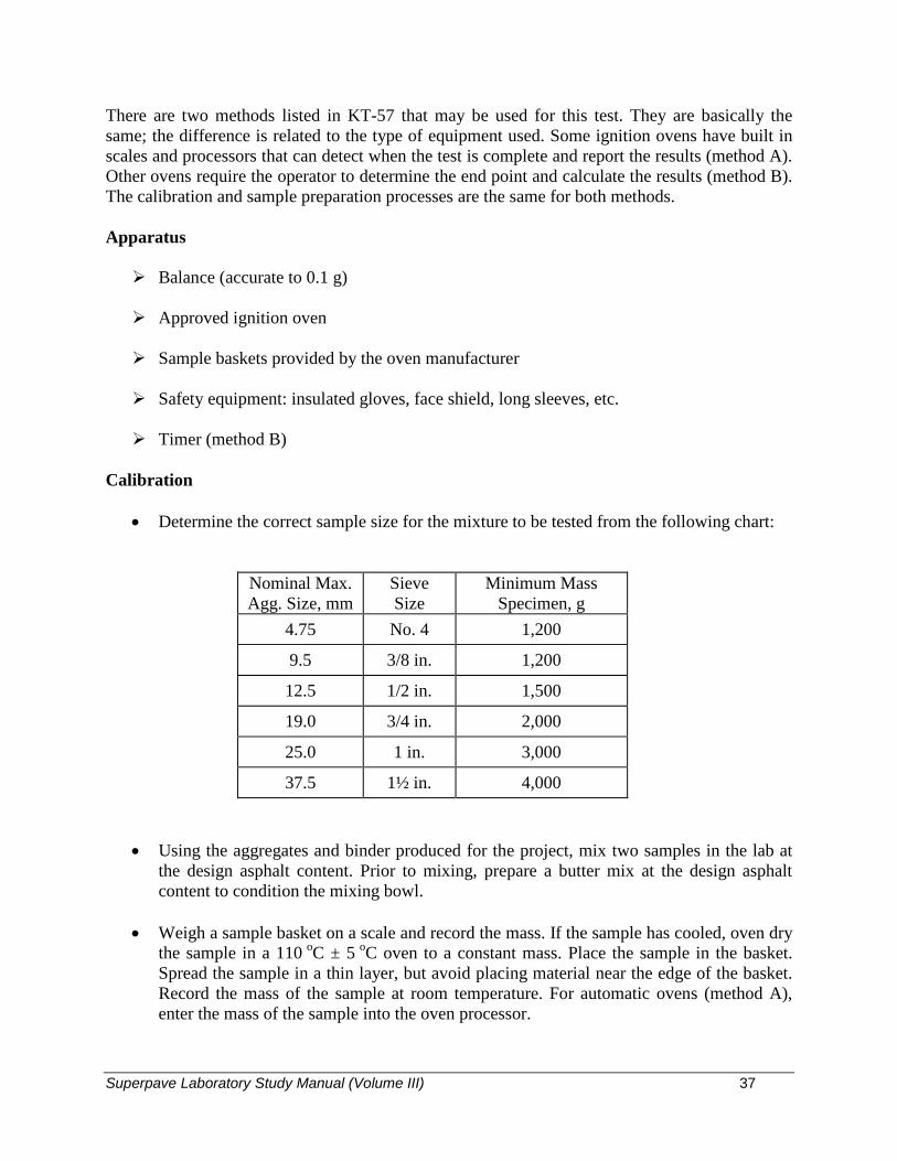
Superpave Laboratory Study Manual (Volume III) 37
There are two methods listed in KT-57 that may be used for this test. They are basically the same; the difference is related to the type of equipment used. Some ignition ovens have built in scales and processors that can detect when the test is complete and report the results (method A). Other ovens require the operator to determine the end point and calculate the results (method B). The calibration and sample preparation processes are the same for both methods.
Apparatus
Balance (accurate to 0.1 g)
Approved ignition oven
Sample baskets provided by the oven manufacturer
Safety equipment: insulated gloves, face shield, long sleeves, etc.
Timer (method B)
Calibration
• Determine the correct sample size for the mixture to be tested from the following chart:
Nominal Max. Agg. Size, mm
Sieve Size
Minimum Mass Specimen, g
4.75 No. 4 1,200
9.5 3/8 in. 1,200
12.5 1/2 in. 1,500
19.0 3/4 in. 2,000
25.0 1 in. 3,000
37.5 1½ in. 4,000
• Using the aggregates and binder produced for the project, mix two samples in the lab atthe design asphalt content. Prior to mixing, prepare a butter mix at the design asphaltcontent to condition the mixing bowl.
• Weigh a sample basket on a scale and record the mass. If the sample has cooled, oven drythe sample in a 110 oC ± 5 oC oven to a constant mass. Place the sample in the basket.Spread the sample in a thin layer, but avoid placing material near the edge of the basket.Record the mass of the sample at room temperature. For automatic ovens (method A),enter the mass of the sample into the oven processor.
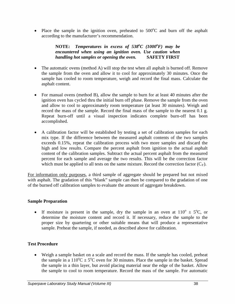
Superpave Laboratory Study Manual (Volume III) 38
• Place the sample in the ignition oven, preheated to 500oC and burn off the asphalt according to the manufacturer’s recommendation.
NOTE: Temperatures in excess of 538oC (1000oF) may be encountered when using an ignition oven. Use caution when handling hot samples or opening the oven. SAFETY FIRST
• The automatic ovens (method A) will stop the test when all asphalt is burned off. Remove
the sample from the oven and allow it to cool for approximately 30 minutes. Once the sample has cooled to room temperature, weigh and record the final mass. Calculate the asphalt content.
• For manual ovens (method B), allow the sample to burn for at least 40 minutes after the
ignition oven has cycled thru the initial burn off phase. Remove the sample from the oven and allow to cool to approximately room temperature (at least 30 minutes). Weigh and record the mass of the sample. Record the final mass of the sample to the nearest 0.1 g. Repeat burn-off until a visual inspection indicates complete burn-off has been accomplished.
• A calibration factor will be established by testing a set of calibration samples for each
mix type. If the difference between the measured asphalt contents of the two samples exceeds 0.15%, repeat the calibration process with two more samples and discard the high and low results. Compare the percent asphalt from ignition to the actual asphalt content of the calibration samples. Subtract the actual percent asphalt from the measured percent for each sample and average the two results. This will be the correction factor which must be applied to all tests on the same mixture. Record the correction factor (CF).
For information only purposes, a third sample of aggregate should be prepared but not mixed with asphalt. The gradation of this “blank” sample can then be compared to the gradation of one of the burned off calibration samples to evaluate the amount of aggregate breakdown. Sample Preparation
• If moisture is present in the sample, dry the sample in an oven at 110o ± 5oC, or determine the moisture content and record it. If necessary, reduce the sample to the proper size by quartering or other suitable means that will produce a representative sample. Preheat the sample, if needed, as described above for calibration.
Test Procedure
• Weigh a sample basket on a scale and record the mass. If the sample has cooled, preheat the sample in a 110oC ± 5oC oven for 30 minutes. Place the sample in the basket. Spread the sample in a thin layer, but avoid placing material near the edge of the basket. Allow the sample to cool to room temperature. Record the mass of the sample. For automatic
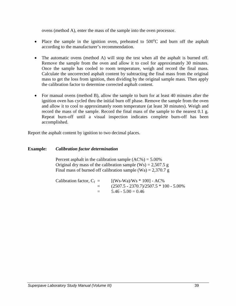
Superpave Laboratory Study Manual (Volume III) 39
ovens (method A), enter the mass of the sample into the oven processor.
• Place the sample in the ignition oven, preheated to 500oC and burn off the asphalt according to the manufacturer’s recommendation.
• The automatic ovens (method A) will stop the test when all the asphalt is burned off.
Remove the sample from the oven and allow it to cool for approximately 30 minutes. Once the sample has cooled to room temperature, weigh and record the final mass. Calculate the uncorrected asphalt content by subtracting the final mass from the original mass to get the loss from ignition, then dividing by the original sample mass. Then apply the calibration factor to determine corrected asphalt content.
• For manual ovens (method B), allow the sample to burn for at least 40 minutes after the
ignition oven has cycled thru the initial burn off phase. Remove the sample from the oven and allow it to cool to approximately room temperature (at least 30 minutes). Weigh and record the mass of the sample. Record the final mass of the sample to the nearest 0.1 g. Repeat burn-off until a visual inspection indicates complete burn-off has been accomplished.
Report the asphalt content by ignition to two decimal places. Example: Calibration factor determination Percent asphalt in the calibration sample (AC%) = 5.00% Original dry mass of the calibration sample (Ws) = 2,507.5 g Final mass of burned off calibration sample (Wa) = 2,370.7 g Calibration factor, Cf = [(Ws-Wa)/Ws * 100] - AC% = (2507.5 - 2370.7)/2507.5 * 100 - 5.00% = 5.46 - 5.00 = 0.46

Superpave Laboratory Study Manual (Volume III) 40
Corrected asphalt content determination: Original dry mass of the test sample = 2,512.4 g Final mass of burned off test sample = 2,379.5 g Corrected asphalt content = [(Ws-Wa)/Ws * 100] - Cf = (2512.4 - 2379.5)/2512.4 * 100 - 0.46% = 5.29% - 0.46% = 4.83% Corrected asphalt content = 4.83%
Asphalt Placed in Basket Basket Placed in Oven

Superpave Laboratory Study Manual (Volume III) 41
1) The sample in KT-57 is obtained by _______________________________. (Quartering/Splitting) 2) The sample in KT-57 is dried at ___________ ± ____ oC to constant mass. 3) For calibration in KT-57, the minimum number of samples required is ___________. 4) Additional tests are necessary in KT-57, if the calibration factors differ by more than ______________%. 5) The sample size in KT-57 test for a nominal maximum aggregate size of 12.5 mm is ________________ g. 6) The ignition furnace used in KT-57 is preheated to ___________________ oC or the
calibration temperature.
Review Questions

Superpave Laboratory Study Manual (Volume III) 42
RESISTANCE OF COMPACTED ASPHALT MIXTURE TO
MOISTURE INDUCED DAMAGE
(Kansas Test Method KT-56 / AASHTO T283)

Superpave Laboratory Study Manual (Volume III) 43
NOTE
This discussion and KT-56 refer to the following KT Methods:
* KT-6/AASHTO T84 & 85, SpecificGravity and Absorption of Aggregate
* KT-14/AASHTO T245 & 269,Marshall Test of Bituminous Mixes
* KT-15/AASHTO T166, Bulk SpecificGravity and Unit Weight of CompactedAsphalt Mixtures
* KT-25/AASHTO T168, StandardMethod of Test for SamplingBituminous Paving Mixtures
* KT-32, Method of Test for Density ofCompacted Asphalt Mixtures byNuclear Method
* KT-39/AASHTO T209, TheoreticalMaximum Specific Gravity of AsphaltPaving Mixtures
* KT-58/AASHTO T312, Method forPreparing and Determining the Densityof Hot Mix Asphalt (HMA) by Meansof the Superpave Gyratory Compactor

Superpave Laboratory Study Manual (Volume III) 44
GLOSSARY
Tensile strength: a measure of the force required to pull apart a material. Loading jack: a mechanical device or machine that can apply a constant rate of loading.

Superpave Laboratory Study Manual (Volume III) 45
Superpave mixtures may be sensitive to the presence of water in the pavement. Water will cause the asphalt to separate from the aggregates. Since the asphalt is the “glue” that holds the aggregates together, rapid failure of the pavement can be expected if the asphalt cannot act as a binder. This phenomenon is often referred to as stripping. To help prevent stripping, additives, such as hydrated lime or liquid anti-stripping chemicals may be required. KT-56/AASHTO T283 is a test method that can be used to determine if the mixtures are susceptible to stripping and can also be used to evaluate the effectiveness of anti-stripping additives.
The test is performed by compacting specimens to an air void level of 6.5 to 7.5 percent. Three specimens are selected as a control set and tested dry without moisture conditioning, and three more are conditioned by saturating with water, then freezing, thawing and hot water soaking. The specimens are then tested for indirect tensile strength by loading at a constant rate and measuring the load required to break the specimen. The average tensile strength of the conditioned specimens is compared to that of the dry, control specimens to determine the tensile strength ratio (TSR). This test may also be performed on cores taken from compacted pavement.
Common Testing Errors
Voids in the conditioned specimens not approximately the same as the dry unconditionedspecimens.
Conditioned specimens not properly saturated with water.
Conditioned specimens not soaked for 24 hours in a water bath at 60 ± 1oC (140 ± 2o F).
RESISTANCE OF COMPACTED ASPHALT MIXTURE TO MOISTURE INDUCED DAMAGE
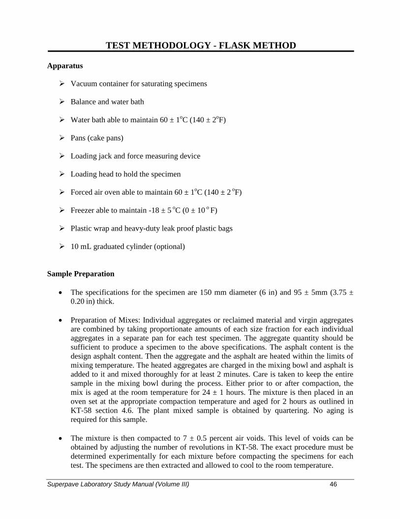
Superpave Laboratory Study Manual (Volume III) 46
Apparatus
Vacuum container for saturating specimens
Balance and water bath
Water bath able to maintain 60 ± 1oC (140 ± 2oF)
Pans (cake pans)
Loading jack and force measuring device
Loading head to hold the specimen
Forced air oven able to maintain 60 ± 1oC (140 ± 2 oF)
Freezer able to maintain -18 ± 5 oC (0 ± 10 o F)
Plastic wrap and heavy-duty leak proof plastic bags
10 mL graduated cylinder (optional)
Sample Preparation
• The specifications for the specimen are 150 mm diameter (6 in) and 95 ± 5mm (3.75 ±0.20 in) thick.
• Preparation of Mixes: Individual aggregates or reclaimed material and virgin aggregatesare combined by taking proportionate amounts of each size fraction for each individualaggregates in a separate pan for each test specimen. The aggregate quantity should besufficient to produce a specimen to the above specifications. The asphalt content is thedesign asphalt content. Then the aggregate and the asphalt are heated within the limits ofmixing temperature. The heated aggregates are charged in the mixing bowl and asphalt isadded to it and mixed thoroughly for at least 2 minutes. Care is taken to keep the entiresample in the mixing bowl during the process. Either prior to or after compaction, themix is aged at the room temperature for 24 ± 1 hours. The mixture is then placed in anoven set at the appropriate compaction temperature and aged for 2 hours as outlined inKT-58 section 4.6. The plant mixed sample is obtained by quartering. No aging isrequired for this sample.
• The mixture is then compacted to 7 ± 0.5 percent air voids. This level of voids can beobtained by adjusting the number of revolutions in KT-58. The exact procedure must bedetermined experimentally for each mixture before compacting the specimens for eachtest. The specimens are then extracted and allowed to cool to the room temperature.
TEST METHODOLOGY - FLASK METHOD

Superpave Laboratory Study Manual (Volume III) 47
Evaluation of Test Specimen and Grouping
• Theoretical maximum specific gravity of the mixture (for design mixture, the sample isprepared at design asphalt content) is determined by KT-39. The specimen thickness isdetermined to the nearest 0.01 mm (0.001 in) at approximately quarter points on theperiphery of the plug. The results are averaged and recorded. The diameter is alsodetermined to the nearest 0.01 mm (0.001 in). The bulk specific gravity is determined byKT-15, Procedure III. Volume of specimens is expressed in mL. The air voids arecalculated to the nearest 0.1% using the following formula:
% Air Voids = 100 (Theoretical Maximum Specific Gravity - Bulk Specific Gravity)/Theoretical Maximum Specific Gravity
• The specimens are sorted into two subsets of three specimens each so that the average airvoids of the two subsets are approximately equal.
Moisture Conditioning
• Put the specimens to be conditioned into the vacuum container and fill with potable waterso that at least 25 mm (1 in.) of water is covering them. Apply a partial vacuum (250 to650 mm of Hg) to the container for a short time (5 to 10 minutes). Release the vacuumand allow the specimens to sit submerged in the water for another 5 to 10 minutes.Determine the bulk specific gravity of the saturated specimens. Compare the saturatedsurface dry (SSD) mass of the saturated specimens to the dry mass of the specimensbefore saturation. The difference will be the volume of absorbed water. Compare thevolume of absorbed water to the original volume of air voids to determine the amount ofsaturation. The volume of absorbed water needs to be between 70 to 80 percent of theoriginal volume of air voids. If the volume of absorbed water is less than 70 percent,repeat the vacuum saturation procedure. If the volume of absorbed water is greater than80 percent, the specimens have been damaged and must be discarded and replaced.
For the freeze cycle, wrap the saturated specimens tightly with plastic wrap and place in aplastic bag with 10 mL of water and seal the bag. Place the bag in the freezer at -18 ± 5oC(0 ± 10 o F) for at least 16 hours. Remove the bags from the freezer and place in the waterbath at 60 ± 1oC (140 ± 2oF) for 24 ± 1 hours. Remove the plastic bag and plastic wrapfrom the specimens as soon as possible after placement in the water bath.
Test Procedure
• After the 24-hour soak, remove the specimens and place in a water bath at 25 ± 0.5oC (77± 1oF) for 2 hours ± 10 minutes. The bath should return to 25 ± 0.5oC (77 ± 1oF) within15 minutes after the warm specimens are placed in the bath. The unconditionedspecimens, still sealed in plastic, also need to be placed in a 25 ± 0.5oC (77 ± 1oF) bath forat least 2 hours ± 10 minutes.

Superpave Laboratory Study Manual (Volume III) 48
• Remove the conditioned plugs from the water bath. Quickly damp dry the saturated specimen with a damp absorbent cloth and weigh the specimen. Any water which seeps from the specimen during the weighing operation is considered part of the saturated specimen. Place the specimen in the basket or bucket and determine its mass to the nearest 0.5 g while immersed in water at 77 ± 1ºF (25 ± 0.5ºC). The mass of the specimen in water shall be determined as quickly as possible after the specimen is immersed. Determine the height and diameter of the plug prior to breaking.
• Place the specimen between the two bearing plates in the loading machine. Apply the
load to the specimen at a constant rate of 51 mm (2 in) per minute. The load should be applied along the diameter of the specimen.
• As the load is applied, watch for and note the maximum load observed. Continue loading
until a vertical crack appears and record the maximum load. Remove the specimen from the machine and pull at the crack. Inspect the interior surface for stripping and record the observations.
Calculations Calculate the tensile strength as follows: St (Metric) = 2,000 (P) / (π)(t)(D) St (English) = 2 (P) / (π)(t)(D) where: St = tensile strength, kPa (psi) P = maximum load, Newtons (lbf) t = specimen thickness, mm (in) D = specimen diameter, mm (in) The tensile strength ratio is then calculated as: Percent Tensile Strength Ratio (%TSR) = 100 (S2) / (S1) where: S1 = average tensile strength of dry subset, and S2 = average tensile strength of conditioned subset. Note: If an anti-stripping agent is used, include the agent in all asphalt mixtures for the
conditioned and unconditioned subsets.

Superpave Laboratory Study Manual (Volume III) 49
Testing Specimens
Specimen in Vacuum Container
Specimen in Bath

Superpave Laboratory Study Manual (Volume III) 50

Superpave Laboratory Study Manual (Volume III) 51
1) The height of the gyratory plug for KT-56 test is approximately _________ ± ________mm. 2) The air voids of the compacted KT-56 specimens should be ____________ ± ______%. 3) If the bulk specific gravity (KT-15, procedure III) of a KT-56 specimen is 2.322 and the maximum specific gravity (KT-39) is 2.444 then the air void content is _______________%. 4) The percent saturation of the conditioned sample in KT-56 should be between _________and
_________%. 5) The test temperature during the indirect tensile strength test in KT-56 is _____________ oC. 6) The conditioned samples in KT-56 are kept in the freezer at ____________± _________ oC
for a minimum of 16 hours. 7) The conditioned samples in KT-56 are thawed in a water bath at _____± _____ oC for
_______ ± ______ hours. 8) In the KT-56 test procedure, load is applied during tensile strength test at a constant rate of
___________________ mm/min.
Review Questions

Superpave Laboratory Study Manual (Volume III) 52
KT-58 1) 115 ± 5 mm2) 600 ± 18 kPa3) 1.16 ± 0.02 º4) 30 ± 0.5 revs/min5) Yes
KT- 15 1) 25 ± 3 oC2) 4 ± 1 min3) 25 ± 1 oC4) 2 %5) 2.349
KT-39 1) 25 ± 1 oC2) 6.3 mm3) 27 ± 3 mm of Hg4) 10 ± 1 min5) 1,500 g6) Quartering7) 38) 2 hours
KT-57 1) Quartering2) 110 ± 5 oC3) 24) 0.15 %5) 1,500 g6) 500 oC
KT-56 1) 95 ± 5 mm2) 7.0 ± 0.5 %3) 5.0 %4) 70 and 805) 25 oC6) -18 ± 5 oC7) 60 ± 1 oC, 24 ± 1 hrs8) 51 mm/min
Answers to Review Questions

Page 1/7 5.9.01 2016
Revised 2014
KT-01
5.9.01 SAMPLING AND SPLITTING OF AGGREGATES (Kansas Test Method KT-1)
1. SCOPE
These methods apply to the sampling of coarse and fine aggregates for quality tests and for inspection and
testing of aggregates being produced for State construction and maintenance work. KT-1 reflects testing
procedures found in AASHTO T 2 and T 248.
Where practicable, samples to be tested for quality shall be obtained from the finished product.
Conditions may require sampling from hauling units or from stockpiles located at the production plant
site or a specified location.
General policy regulations covering the frequency of and procedures for sampling aggregates are set forth
in Part V, Section 5.6 of this manual.
2. REFERENCED DOCUMENTS
2.1. KDOT Construction Manual, Part V, Section 5.6; Aggregates
2.2 AASHTO T 2; Sampling of Aggregates
2.3. AASHTO T 248; Reducing Samples of Aggregate to Testing Size
3. SAMPLING METHODS
3.1. Sampling from Discharge or Flowing Streams:
Obtain at least three approximately equal sample increments, selected at random from the stream and
combine to form a field sample that equals or exceeds the minimum required mass. Take each increment
from the entire cross section of the material as it is being discharged. It is usually necessary to have a
special device constructed for a particular plant. This device consists of a pan of sufficient size to
intercept the entire cross section of the discharge stream and hold the required quantity of material
without overflowing. A set of rails may be necessary to support the pan as it is passed under the
discharge stream. The use of heavy equipment, such as a loader, may also be enlisted for this purpose.
Sampling the initial discharge or the final few tons from a bin or conveyor belt increases the chance of
obtaining segregated material and should be avoided. To the extent possible, keep bins continuously full
to reduce segregation.
3.2 Sampling from a Stationary Conveyor Belt:
Only when the belt is completely stopped and easily within reach, should belt samples be obtained.
Never walk on a stopped conveyor belt. Elevated conveyors must be equipped with a suitable walkway
and necessary fall protection must be utilized. An individual obtaining a conveyor belt sample must have
their own lock out/tag out device(s) in place during sampling.
Insert two templates, the shape of which conform to the shape of the belt, in the aggregate stream on the
belt. Carefully scoop all material between the templates into a suitable container and collect the fines
from the belt with a brush and dust pan and add to the container. Obtain at least three approximately
equal increments, selected at random, and combine to form a field sample with a mass that equals or
exceeds the minimum.
Page 2/7 5.9.01 2016
Revised 2014
KT-01
3.3. Sampling from Stockpiles:
When possible, avoid sampling from stockpiles. It is very difficult to ensure unbiased samples due to the
segregation which often occurs when material is stockpiled with coarse particles rolling to the outside
base of the pile.
Loaders must be used to scoop material from the main stockpile and create a separate smaller stockpile.
This should be done by loading out a minimum of three buckets from various heights and locations
around the main pile and dumping each load on top of the previous in a separate location. When feasible,
stockpiles under production can be sampled by moving the stacking or conveyor equipment in order to
create the smaller pile for sampling.
For coarse aggregate, the loader should flatten one side of the pile by inserting the bucket vertically at or
near the apex of the pile, and backing the material out away from the pile. The flattened material should
then be sampled by inserting a shovel vertically in at least 5 different locations. Combine the individual
increments to produce a field sample weighing not less than 75 lb (35 kg), mix thoroughly and reduce to
the specified size for testing.
For fine aggregate, collect the sample using a sampling tube or shovel. Sample fine aggregate with a
sampling tube having a diameter at least three times the size of the maximum size aggregate being
sampled. Scalp away the outer layer of fine aggregate to assure the sample has not become segregated.
Obtain a minimum of five increments at several locations in the pile with samples taken from each 1/3
volume of the pile by inserting the tube or digging a hole 1 to 2 ft (0.3 to 0.6 m) deep. Combine the
individual increments to form a field sample, mix and reduce to proper size for testing.
3.4. Plant Mixed Aggregate: There are several acceptable methods of taking samples from each type of
plant. Every situation should be studied and evaluated to determine whether or not the method to be used
will provide a representative sample of the material being produced. Plant mixed aggregate samples are
generally obtained by one of the following procedures. If these procedures, due to unforeseen
circumstances, prove to be unworkable, other procedures may be used if approved in writing by the
District Materials Engineer.
3.4.1. Apparatus.
3.4.1.1. For Asphalt Plant Sampling.
3.4.1.1.1. For Batch Plants: A vertical receptacle having a closed bottom and an open top with no
dimension in the opening of less than 5 in (125 mm). Appropriate handles for lifting and handling and a
wide flat base for vertical stability are recommended. The height of the container must be sufficient that
it will not over flow during the discharge of material from the pugmill.
Some containers have been designed to automatically split the material that enters the opening into two or
more portions and discard one-half or more of all material received.
3.4.1.1.2. Continuous Flow Plants: A horizontal trough having a minimum width of 5 in (125 mm), a
minimum depth of 12 in (300 mm), and a length equal to or greater than the width of the pugmill
discharge stream., so constructed that it can be passed through the pugmll stream in a horizontal plane.
Appropriate handles for lifting and handling are required. The apparatus shall meet the requirements in
Section 3.1., of this test method and be approved by the District Materials Engineer.

Page 3/7 5.9.01 2016
Revised 2014
KT-01
3.4.1.2. For Screenless Operation Sampling: The apparatus shall meet the requirements in Section 3.1. of
this test method and be approved by the District Materials Engineer.
3.4.2. Procedure.
3.4.2.1. For Asphalt Plant Sampling.
3.4.2.1.1. Batch Plant: Center the container under the pugmill discharge, open the gate and empty the
pugmill before removing the container.
3.4.2.1.2. Continuous Flow Plants: Pass the container horizontally through the drum discharge stream in
such a manner that a representative sample will be obtained, and the container will not be filled to
overflowing.
3.4.2.2. For Screenless Operation Sampling: The contractor shall provide a system for sampling the
combined material ahead of the mixing chamber. Such a system must be approved by the District
Materials Engineer.
3.5. Windrows: Windrows are not to be sampled until all blending and mixing is completed. They must
be sampled by methods that will insure that the sample will be representative of the material within the
windrow cross section at the point of sampling. Power equipment is helpful in cutting through a windrow
prior to sampling and should be used whenever available. Samples should be ample size to be
representative of the windrow at the point of sampling and reduced to proper size for testing.
It has been determined that windrows containing aggregate with not more than 10% of material retained
on the 3/8 in (9.5 mm) sieve and not more than 25% crushed material may be effectively sampled with a
standard sampling tube.
To provide an acceptable sample, the following conditions are required:
3.5.1. A properly mixed and well “peaked” windrow.
3.5.2. Force the tube into the windrow and equal number of times, well-spaced, on each side of the
windrow, and in a direction normal to the slope of the windrow face.
3.5.3. Sample size is sufficient for reduction by splitting using the standard procedure. Not less than 75 lb
(35 kg) sample is recommended.
3.6. Unopened Sand-gravel Deposits: Unopened deposits of sand-gravel are usually explored by drilling
test holes spaced at regular intervals over the area underlaid by the deposit. The holes are extended
through the soil and other non-usable over-burden and through the workable depth of the deposit.
Remove the sand-gravel from each test hole and examine for major changes in the quality and gradation
characteristics, then record such changes. Place all usable material removed from each test hole on a
quartering canvas, sheet of plywood, or other material to prevent contamination from grass, top soil, etc.
Thoroughly mix a 15 lb (7 kg) sample for gradation tests.
If the quality of the material removed from all test holes appears to be reasonably uniform, a sufficient
amount of material from each test hole should be obtained to produce a 200 lb (90 kg) composite sample
for quality testing. This sample will be tested for information only.

Page 4/7 5.9.01 2016
Revised 2014
KT-01
4. SAMPLE REDUCTION
4.1. Quartering Canvas Procedure: Samples that weigh 75 lb (35 kg) or more may be reduced to one-half
size by using a quartering canvas. The canvas is not to be used as the first step in the reduction of
samples smaller than approximately 75 lb (35 kg).
4.1.1. Spread the canvas on a smooth level surface. Dump the sample in a pile near the center and mix by
alternately lifting each corner and rolling the aggregate toward the opposite corner. This should be
performed in a vigorous manner.
4.1.2. Center the material on the canvas in a uniform pile. Flatten the pile to a uniform thickness and
diameter by pressing down the apex with a straight-edge scoop, shovel, or trowel (depending on the size
of sample). Press down so that each quarter sector of the resulting pile will contain the material originally
in it. The diameter should be approximately four to eight times the thickness.
4.1.3. Insert a rod, shovel handle, or similar object under the canvas and under the center of the pile and
lift both ends of the rod to divide the pile into two equal parts. Remove the stick leaving a fold of the
blanket between the divided portions. Insert the rod under the canvas and under the center of the resulting
two piles at right angles to the first division and again lift the rod to divide the sample into four equal
parts.
4.1.4. Discard two opposite quarters, combine the two remaining quarters, mix and reduce to proper size
with a riffle splitter or by repeating the quartering procedure.
When a quartering canvas is used, the Field Engineer and District Materials Engineer should be certain
that proper procedures are being followed at all times.
4.2. Riffle Splitter: The initial sample size shall be at least four times the size of the required test portion.
If use of this method is desired and the sample has free moisture on the particle surfaces, the entire sample
must be dried to at least the saturated-surface-dry condition (SSD) using temperatures that do not exceed
those specified for any tests contemplated. If the moist sample is very large, a preliminary split may be
made using a mechanical splitter having wide chute openings 1 1/2 in (37.5 mm) or more to reduce the
sample to not less than 5000 g.
4.2.1. Apparatus: The splitter shall have an even number of equal width chutes, not less than a total of
eight for coarse aggregate, or twelve for fine-aggregate, which discharge alternatively to each side of the
splitter. For coarse and mixed aggregate the minimum width of the individual chutes shall be
approximately 50% larger than the largest particles in the sample to be split. For dry fine aggregate, finer
than the 3/8 inch (9.5 mm) sieve, a splitter having chutes 1/2 to 3/4 inches (12.5 to 19 mm) wide shall be
used. The splitter shall be equipped with two receptacles to hold the two halves of the sample following
splitting. A hopper or straight-edged pan, with a width equal to or slightly less than the overall width of
the assembly of chutes, shall be used to feed the sample at a controlled rate to the chutes. The splitter and
accessory equipment shall be designed so the sample will flow smoothly without restriction or loss of
material.
NOTE: Any disputed samples shall be split using the appropriate splitter meeting the above
specifications.
4.2.2. Place the original sample in the hopper or pan and uniformly distribute it from edge to edge, so that
when it is introduced into the chutes, approximately equal amounts will flow through each chute. The
rate at which the sample is introduced shall allow free flowing through the chutes into the receptacles
Page 5/7 5.9.01 2016
Revised 2014
KT-01
below. Reintroduce the portion of the sample in one of the receptacles into the splitter as many times as
necessary to reduce the sample to the size specified for the intended test.
4.3. Miniature Stockpile Sampling Procedure: This method of sample reduction may be used only on wet
fine aggregate. For this quartering procedure, wet is defined as free moisture on the surface as
approximated by the fine aggregate retaining its shape when molded by hand.
Place the sample on a clean, hard, level surface where there will be neither loss of material nor the
accidental addition of foreign material. The initial sample size shall be at least four times the size of the
required test portion. Mix the sample thoroughly with a shovel by turning it over completely three times.
With the last turning, shovel the entire sample into a conical pile by depositing each shovelful on top of
the preceding one. Carefully flatten the conical pile to a uniform thickness and diameter by pressing
down on the apex with a shovel so that each quarter sector of the resulting pile will contain the material
originally in it. The diameter should be approximately four to eight times the thickness. Divide the
flattened pile into four equal quarters with a straight edge (trowel or similar metal blade) and remove two
pre-selected diagonally opposite quarters, using a brush or broom to clean the cleared space. Repeat the
process until the sample is reduced to the proper size.

Page 6/7 5.9.01 2016
Revised 2014
KT-01
Quartering on a Hard, Clean, Level Surface
COCO
Cone Sample on
Hard Clean Surface
Mix by
Forming New
Cone
Quarter after
Flattening Cone
Sample divided into
Quarters
Retain opposite
Quarters, Reject the
other Two Quarters

Page 7/7 5.9.01 2016
Revised 2014
KT-01
Quartering on a Canvas Blanket
Stick Placed under flattened Sample divided in half Sample divided into quarters cone
Mix by Rolling on
Blanket
Form Cone After
Mixing
Quarter after flattening Cone.
Retain Opposite Quarters. Reject the Other Two Quarters.

Page 1/8 5.9.02 2016
Revised 2016
KT-02
5.9.02 SIEVE ANALYSIS OF AGGREGATES (Kansas Test Method KT-2)
1. SCOPE
This method of test covers procedures for the determination of the particle size distribution of aggregates
using standard sieves. KT-2 reflects testing procedures found in AASHTO T 27.
2. REFERENCED DOCUMENTS
2.1. Part V, 5.9; Sampling and Test Methods Foreword
2.2 KT-1; Sampling and Splitting of Aggregates
2.3. KT-3; Material Passing No. 200 (75µm) Sieve by the Wash Method
2.4. AASHTO M 92; Wire-Cloth Sieves for Testing Purposes
2.5. AASHTO T 27; Sieve Analysis of Fine and Coarse Aggregates
3. APPARATUS
3.1. The balance shall be readable to 0.1% of the sample mass and conform to the requirements of Part
V, Section 5.9; Sampling and Test Methods Foreword of this manual for the class of general purpose
balance required for the principal sample mass of the sample being tested.
3.2. Sieves meeting AASHTO M 92. As a minimum, set of sieves will include the 3/8 in (9.5 mm), No.
4 (4.75 mm), No. 8 (2.36 mm), No. 16 (1.18 mm), No. 30 (600 µm), No. 50 (300 µm), No. 100 (150 µm)
and No. 200 (75 µm) for all aggregates. Gradations with larger sized aggregate will require addition of
appropriate larger sieves to the set.
3.3. A mechanical sieve shaker, if used, shall impart a vertical, or lateral and vertical motion to the sieve,
causing the particles to bounce and turn so as to present different orientations to the sieving surface. The
sieving action shall be such that the criterion for adequacy of sieving is met in a timely manner as
described in Section 6.3 of this test method.
3.4. An oven of appropriate size capable of maintaining a uniform temperature of 230 + 9°F (110 + 5°C).
3.5. Drying pans.
4. SAMPLES
4.1. Composition: Obtain samples for sieve analysis by the use of a sample splitter or by the method of
quartering. Fine aggregate sampled by the quartering method shall be thoroughly mixed and in a moist
condition. The sample for test shall be approximately the mass desired and shall be the end result of
proper reduction methods. Do not attempt the selection of samples of an exact predetermined mass.
4.2. Fine Aggregates: Sample of fine aggregate for sieve analysis shall have a mass, after drying, not less
than 300 g.
4.3. Coarse Aggregate: Samples of coarse aggregate and mixtures of coarse and fine aggregate for sieve
analysis shall have a mass, after drying, not less than the amounts indicated in Table 1.
Page 2/8 5.9.02 2016
Revised 2016
KT-02
Table 1
Sample Size for Determination of
Coarse Aggregate Gradation Tests
Sieve Size Minimum Mass of Samples (g)
2 1/2 in (63 mm) or more 35,000
2 in (50 mm) 20,000
1 1/2 in (37.5 mm) 15,000
1 in (25.0 mm) 10,000
3/4 in (19.0 mm) 5,000
1/2 in (12.5 mm) 2,000
3/8 in (9.5 mm) or less 1,000
NOTE: To select the sample size, use the largest sieve on which 5% or more of the material is specified
to be retained.
NOTE: 12.00 in (300 mm) diameter sieves should be used for testing coarse aggregates and in testing
samples with a mass of 5,000 g or more. If 12.00 in (300 mm) diameter sieves are not available, the split
sample procedure in Section 7.2 of this test method shall be used.
5. PREPARATION OF SAMPLES
NOTE: Remove deleterious material prior to determining original dry mass if required by relevant
specifications.
5.1. Dry all samples to a constant mass at a temperature of 230 + 9°F (110 + 5°C). Determine the mass of
the sample to the nearest 0.1%. Record this as the original dry mass.
5.1.1. In the case of Cold in Place Recycle, air drying is acceptable.
5.2. Wash the sample over the No. 200 (75µm) sieve as specified in KT-3, Section 5.2. Then redry the
sample to constant mass. Determine the mass of the sample to the nearest 0.1% of the original dry mass.
Record this as the dry mass of sample after washing.
NOTE: For lightweight aggregate cover material: Dry-screen lightweight aggregate cover material
according to KT-4 instead of washing. Remove and discard all deleterious material from the sample
including clay lumps retained on the No.4 (4.75 mm) sieve before the mass of the sample after dry-
screening is determined.
5.3. For convenience, mixtures of coarse and fine aggregates may be separated into two portions by
screening the dried sample over a No. 4 (4.75 mm) sieve.
5.3.1 Reduce the material passing the No. 4 (4.75 mm) sieve by means of a sample splitter to a mass of
approximately 1,000 g. Wash both the coarse and reduced fine portions of the total sample in accordance
with KT-3, Section 5.2, and conduct a sieve analysis on each portion. Calculate the total combined
grading in accordance with subsection Section 7.2 of this test method.
6.1 TEST PROCEDURES
Page 3/8 5.9.02 2016
Revised 2016
KT-02
6.1. Nest the sieves in order of decreasing size of opening from top to bottom and place the sample, or
portion of the sample, if it is to be sieved in more than one increment, on the top sieve. Agitate the sieves
by hand or by mechanical apparatus for a sufficient period, established by trial or checked by
measurement on the actual test sample, to meet the criterion for adequacy of sieving described in Section
6.3. of this test method.
6.2. Limit the quantity of material on a given sieve so that all particles have opportunity to reach sieve
openings a number of times during the sieving operation. For sieves with openings smaller than No. 4
(4.75 mm) the mass retained on any sieve at the completion of the sieving operation shall not exceed 4
g/in2 (7 kg/m
2) of sieving surface. For sieves with openings No. 4 (4.75 mm) and larger, the mass in
kg/m2 of sieving surface shall not exceed the product of 2.5 times the sieve opening in mm. In no case
shall the mass be so great as to cause permanent deformation of the sieve cloth.
NOTE: The 4 g/in2 (7 kg/m
2) amounts to 194 g for the usual 8 in (203 mm) diameter sieve. The amount
of material retained on a sieve may be regulated by (1) the introduction of a sieve with larger openings
immediately above the given sieve or (2) testing the sample in a number of increments.
6.3. Continue sieving for a sufficient period and in such a manner that, after completion, not more than
0.5% by mass of the total sample passes any sieve during one minute of continuous hand sieving
performed as follows: Hold the individual sieve, provided with a snug fitting pan and cover, in a slightly
inclined position in one hand. Strike the side of the sieve sharply and with an upward motion against the
heel of the other hand at the rate of about 150 times per minute, turn the sieve about one-sixth of a
revolution at intervals of about 25 strokes. In determining sufficiency of sieving for sizes larger than the
No. 4 (4.75 mm) sieve, limit the material on the sieve to a single layer of particles. If the size of the
mounted testing sieves makes the described sieving motion impractical, use 8 in (203 mm) diameter
sieves to verify the sufficiency of sieving.
6.3.1. 1 An alternative to maintain a snug fitting pan and cover is to sieve the material over an oversized
pan. The pan must be large enough to ensure all material is retained during the hand sieving process.
Any material leaving the sieve over the top of the rim must be returned to the sieve.
6.4. In the case of coarse and fine aggregate mixtures, the portion of the sample finer than the No. 4 (4.75
mm) sieve may be distributed among two or more sets of sieves to prevent overloading of individual
sieves.
6.4.1. Alternatively, the portion finer than the No. 4 (4.75 mm) sieve may be reduced in size using a
mechanical splitter according to KT-1, Section 4.2. If this procedure is followed, compute the mass of
each size increment of the original sample as outlined in Section 7.2. of this test method.
6.5. Determine the mass of each sieve size increment to the nearest 0.1% of the total original dry sample
mass (as define in Section 5.1. of this test method) by weighing on a scale or balance conforming to the
requirements specified in Section 3.1. of this test method. The total mass of the material after sieving
should check closely with original mass of sample placed on the sieves. If the amounts differ by more
than 0.3%, based on the original mass of sample placed on the sieves, the results should not be used for
acceptance purposes.
6.6. If the sample has previously been tested by KT-3, add the mass finer than the No. 200 (75 μm) sieve
determined by that method to the mass passing the No. 200 (75 μm) sieve by sieving of the same sample
in this method.
1 6.3.1. is not found in AASHTO T 27 but provides a realistic approach to monitoring material falling thru the sieve.

Page 4/8 5.9.02 2016
Revised 2016
KT-02
7. CALCULATIONS
7.1 Calculate the total percent of material retained on each sieve as follows:
Percent Retained= 100 (Mass Retained)
Total Original Dry Mass of Sample
Percent Passing No. 200 (75 µm)=
100 (Sum of material Passing No. 200 (75 μm) by Sieve and Wash )
Total Original Dry Mass of Sample
7.2. Instructions for using split sample procedure (KDOT Form #645):
7.2.1. Record the total dry mass of sample before separation as A.
7.2.2. Record the total dry mass of material retained on No. 4 (4.75 mm) sieve following separation as B.
7.2.3. Record the total dry mass of material passing the No. 4 (4.75 mm) sieve following separation as C.
C=A-B
7.2.4. Record reduced mass of material passing the No. 4 (4.75 mm) sieve as D.
7.2.5. Compute percent of material passing the No. 4 (4.75 mm) sieve as follows:
𝐸 =100(C)
A
Where : E= percent of material passing the No. 4 (4.75 mm) sieve in the total sample.
7.2.6. Wash the plus No. 4 (4.75 mm) portion of the sample over the No. 200 (75 µm) sieve as specified
in KT-3, dry to a constant mass. Weigh and record the mass. Conduct sieve analysis using all regular
sieves including the No. 200 (75 µm). Compute the percent of material retained on each sieve as follows:
𝐺 =100(F)
A
Where: G= Total percent of the entire sample that is retained on each sieve.
F= Total mass of the plus No. 4 (4.75mm) material retained on each sieve size.
Calculate the total percent of material finer than the No. 200 (75 μm) sieve for the plus No. 4 fraction of
the original sample by adding the mass determined by KT-3 to the mass passing the No. 200 (75 μm)
sieve by dry sieving, multiplying by 100 and divide by total dry mass of the sample before separation:
𝑄 =100(Sum of material Passing No. 200 (75 μm) by Sieve and Wash)
A

Page 5/8 5.9.02 2016
Revised 2016
KT-02
Where: Q= Total percent of the plus No. 4 (4.75 mm) sieve passing the No. 200 (75 µm) sieve.
7.2.7. Wash the reduced sample of minus No. 4 (4.75 mm) material over a No. 200 (75 µm) sieve as
specified in KT-3, dry to a constant mass. Weigh and record the mass. Conduct sieve analysis using all
regular sieves including the No. 200 (75 µm). Compute the total percent of the reduced minus No. 4
(4.75 mm) sample retained on each sieve as follows:
𝐽 =100(H)
D
Where: J= Total percent of the reduced minus No. 4 (4.75 mm) sample retained on each sieve.
H=Total mass of the reduced minus No. 4 (4.75 mm) material retained on each sieve.
D= Total dry mass of reduced minus No. 4 (4.75 mm).
Calculate the total percent of material finer than the No. 200 (75 μm) sieve for the plus No. 4 (4.75 mm)
fraction of the original sample by adding the mass determined by KT-3 to the mass passing the No. 200
(75 μm) sieve by dry sieving, multiplying by 100 and divide by total dry mass of reduced minus No. 4
(4.75 mm):
𝑆 =100(Sum of material Passing No. 200 (75 μm) by Sieve and Wash)
D
Where: S= Total percent of reduced minus No. 4 (4.75 mm) material passing the No. 200
(75 µm) sieve
7.2.8. Calculate the adjusted percent retained on each size sieve for the minus No. 4 (4.75 mm) material
as follows:
𝐾 =(J)(E)
100
Where: K=Adjusted percent of minus No. 4 (4.75 mm) material.
J=Total percent of reduced minus No. 4 (4.75 mm) sample retained on each sieve.
E=Percent of minus No. 4 (4.75 mm) material in total sample.
7.2.9. Calculate the combined percentage of material retained on each sieve in the series as follows:
R=K+G
7.2.10 Calculate the total material finer than the No. 200 (75 μm) sieve for the original sample as follows:
Total % Passing No. 200 (75 μm) Sieve = Q +(S)(E)
100
7.2.11. Record the sieve analysis on the proper KDOT form.
NOTE: The use of the “Work Sheet for Split Sample Gradation and Plastic Index Tests”, KDOT Form
No. 645, is provided for the above calculations.

Page 6/8 5.9.02 2016
Revised 2016
KT-02
8. REPORTING
The results of the sieve analysis and, when required, the percent passing the No. 200 (75 µm) sieve by the
Wash Method (KT-3) are reported on appropriate KDOT forms. Report gradation test results to the
nearest whole percent, except for when the percentage passing the No. 200 (75 µm) sieve is less than
10%, it shall be reported to the nearest 0.1% , unless otherwise directed (most asphalt mix gradations are
rounded to the nearest 0.01%). The project number, name of producer, location of deposit, and all other
pertinent data are shown on each report.
The first aggregate report issued for each project shall list the laboratory number under which the latest
Official Quality Sample was tested and the results of such tests with the exception that specific gravities
will be reported only if required by the specification. Subsequent reports may list only the laboratory
number which the quality tests were conducted.
9. PRECISION
Precision for sieving aggregates are established in TABLE 2. The estimates for precision are based on
results from the AASHTO Materials Reference Laboratory Reference Sample Program.
TABLE 2
Total percentage of
Material Passing
Standard Deviation
(1S), %
Acceptable Range of
Two Results (D2S), %
Coarse Aggregates:
Single-Operator Precision
<100 >95 0.32 0.9
<95 >85 0.81 2.3
<85 >80 1.34 3.8
<80 >60 2.25 6.4
<60 >20 1.32 3.7
<20 >15 0.95 2.7
<15 >10 1.00 2.8
<10 >5 0.75 2.1
<5 >2 0.53 1.5
<2 >0 0.27 0.8
Multilaboratory Precision
<100 >95 0.35 1.0
<95 >85 1.37 3.9
<85 >80 1.92 5.4
<80 >60 2.82 8.0
<60 >20 1.97 5.6
<20 >15 1.60 4.5
<15 >10 1.48 4.2
<10 >5 1.22 3.4
<5 >2 1.04 3.0
<2 >0 0.45 1.3
Fine Aggregates:
Single-Operator Precision
<100 >95 0.26 0.7
<95 >60 0.55 1.6
<60 >20 0.83 2.4
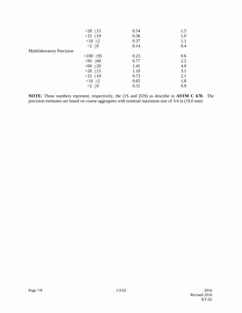
Page 7/8 5.9.02 2016
Revised 2016
KT-02
<20 >15 0.54 1.5
<15 >10 0.36 1.0
<10 >2 0.37 1.1
<2 >0 0.14 0.4
Multilaboratory Precision
<100 >95 0.23 0.6
<95 >60 0.77 2.2
<60 >20 1.41 4.0
<20 >15 1.10 3.1
<15 >10 0.73 2.1
<10 >2 0.65 1.8
<2 >0 0.31 0.9
NOTE: These numbers represent, respectively, the (1S and D2S) as describe in ASTM C 670. The
precision estimates are based on coarse aggregates with nominal maximum size of 3/4 in (19.0 mm)

Page 8/8 5.9.02 2016 Revised 2016
KT-02
Page 1/4 5.9.03 2016
Revised 2014
KT-03
5.9.03 MATERIAL PASSING NO. 200 (75µm) SIEVE BY THE WASH METHOD
(Kansas Test Method KT-3)
1. SCOPE
This method of test covers the procedure for determining the quantity of material finer than the No. 200
(75µm) sieve in aggregate by the wash method. It should be recognized that this procedure will not
determine the total amount of material finer than the No. 200 (75µm) sieve and that the total amount must
be determined by a combination of washing, drying and re-screening as outlined in KT-2 of this manual.
KT-3 reflects testing procedures found in AASHTO T 11.
2. REFERENCED DOCUMENTS
2.1. Part V, 5.9; Sampling and Test Methods Foreword
2.2. KT-2; Sieve Analysis of Aggregates
2.3. KT-7; Clay Lumps and Friable Particles in Aggregate
2.4. AASHTO M 92; Wire-Cloth Sieves for Testing Purposes
2.5. AASHTO T 11; Materials Finer Than No. 200 (75µm) Sieve in Mineral Aggregates by Washing
3. APPARATUS
3.1. A nest of two sieves, the lower being a No. 200 (75µm) sieve and the upper being a sieve with
openings in the range of No. 8 (2.36 mm) to No. 16 (1.18 mm), both conforming to the requirement of
AASHTO M 92.
3.2. A pan or vessel of a size sufficient to contain the sample covered with water and to permit vigorous
agitation without loss of any part of the sample or water.
3.3. Drying pans.
3.4. The balance shall conform to the requirements of Part V, 5.9, Sampling and Testing Methods
Foreword for the class of general purpose balance required for the principal sample mass of the sample
being tested.
3.5. Oven capable of maintain uniform temperature of 230 + 9°F (110 + 5°C).
3.6. Wetting Agent—Any dispersing agent, such as liquid dishwashing detergents, that will promote
separation of the fine materials.
NOTE: The use of a mechanical apparatus to perform the washing operation is not precluded, provided
the results are consistent with those obtained using manual operations. The use of some mechanical
washing equipment with some samples may cause degradation of the sample.
Page 2/4 5.9.03 2016
Revised 2014
KT-03
4. TEST SAMPLE
Select the test sample from material that has been thoroughly mixed. Except for plant dried aggregate,
the material from which the sample is selected should contain sufficient moisture to prevent segregation.
Select a representative sample of sufficient size to yield not less than the mass of dried material shown in
Table 1.
Table 1
Sample Size for Determination of Percent of Material
Passing No. 200 (75 µm) Sieve by Washing
Sieve Size Minimum Mass of Samples (g)
1 1/2 in (37.5 mm) or more 5,000
3/4 in (19.0 mm) 2,500
3/8 in (9.5 mm) 1,000
No. 4 (4.75 mm) or less 300
NOTE: To select the sample size, use the largest sieve on which 5% or more of material is specified to be
retained.
NOTE: Monitor test samples for clay lumps. The percent of clay lumps permitted in these aggregates is
covered by a separate specification for the following materials and the method of determination is
covered by KT-7:
Concrete (except lightweight aggregate).
Underdrain.
Cover Material.
Subgrade Modification or Reconstruction.
Surfacing or Resurfacing.
Surfacing or Subgrade Modification for Secondary Roads.
Crushed Stone for Backfill.
5. TEST PROCEDURE
5.1. Dry the sample to constant mass at a temperature of 230 + 9°F (110 + 5°C). Determine the mass of
the sample to the nearest 0.1%. Record this as the original dry mass.
5.2. Place the test sample in the container. Add sufficient water to cover the sample, and add wetting
agent to the water. Agitate the sample with sufficient vigor to result in complete separation of all particles
finer than the 75-μm (No. 200) sieve from the coarser particles, and to bring the fine material into
suspension. The use of a large spoon or other similar tool to stir and agitate the aggregate in the wash
water has been found satisfactory. Immediately pour the wash water containing the suspended and
dissolved solids over the nested sieves, as described in Section 3.1. of this test method, arranged with the
coarser sieve on top. Take care to avoid, as much as feasible, the decantation of coarser particles of the
sample.
NOTE: There should be enough wetting agent to produce a small amount of suds when the sample is
agitated. The quantity will depend on the hardness of the water and the quality of the detergent. Excessive
suds may overflow the sieves and carry some material with them.

Page 3/4 5.9.03 2016
Revised 2014
KT-03
5.3. Add a second charge of water (without wetting agent) to the sample in the container, agitate, and
decant as before. Repeat this operation until the wash water is clear.
NOTE: A spray nozzle or a piece of rubber tubing attached to a water faucet may be used to rinse any of
the material that may have fallen onto the sieves. The velocity of water, which may be increased by
pinching the tubing or by use of a nozzle, should not be sufficient to cause any splashing of the sample
over the sides of the sieve.
Return all material retained on the nested sieves by flushing to the washed sample.
Following the washing of the sample and flushing any materials retained on the 75-μm (No. 200) sieve
back into the container, no water should be decanted from the container except through the 75-μm sieve,
to avoid loss of material. Excess water from flushing should be evaporated from the sample in the drying
process.
If mechanical wash equipment is used, the charging of water, agitating, and decanting may be a
continuous operation.
5.4. Dry all material retained to constant mass at a temperature of approximately 230 + 9°F (110 + 5°C).
Weigh the sample to the nearest 0.1% of the original dry mass. Record this as the final dry mass.
6. CALCULATIONS
Calculate the results by use of the following formula:
𝑃 =100(ODM− FDM)
ODM
Where: P = Percent of material finer than No. 200 (75 µm).
ODM= Original Dry Mass.
FDM= Final Dry Mass (after washing).
7. CHECK DETERMINATIONS
When check determinations are desired either evaporate the wash water to dryness or filter it through
tared filter paper which shall subsequently be dried and the residue weighed. Calculate the percentage by
use of the following formula:
𝑃 =100(MR)
ODM
Where: P = Percent of material finer than No. 200 (75 µm).
MR= Mass of Residue.
ODM= Original Dry Mass.

Page 4/4 5.9.03 2016
Revised 2014
KT-03
8. REPORT
Record the material passing the No. 200 (75 µm) sieve by the wash method to 0.1% of the original mass.
Report the percentage of material finer than the No. 200 (75 µm) sieve by washing to the nearest 0.1%,
except if the result is 10% or more, report the percentage to the nearest whole number.
9. PRECISION
The estimates for precision of this test method are based on the results from the AASHTO Materials
Reference Laboratory Proficiency Sample Program and are presented in Table 2.
Table 2
Standard Deviation (1S), Percent Acceptable Range of two Results
(D2S), Percent
Coarse aggregate:
Single operator precision 0.10 0.28
Multilaboratory precision 0.22 0.62
Fine aggregate:
Single operator precision 0.15 0.43
Multilaboratory precision 0.29 0.82

Page 1/3 5.9.04 2016
Revised 2014
KT-04
5.9.04 PERCENT RETAINED ON THE NO. 200 (75 µm) SIEVE BY DRY SCREENING
(Kansas Test Method KT-4)
1. SCOPE
This method of test covers the procedure for determining the amount of material retained on the No. 200
(75 µm) sieve by dry screening only.
NOTE: When the percent retained on the No. 200 (75 µm) sieve by dry screening is part of the project
specifications, it is common practice to conduct KT-4 followed by KT-2 on the sample.
2. REFERENCED DOCUMENTS
2.1. Part V, 5.9; Sampling and Test Methods Foreword
2.2. KT-2; Sieve Analysis of Aggregates
2.3. AASHTO M 92; Wire-Cloth Sieves for Testing Purposes
3. APPARATUS
3.1. The balance shall conform to the requirements of Part V, 5.9; Sampling and Test Methods
Foreword, for the class of general purpose balance required for the principal sample mass of the sample
being tested.
3.2. Sieves meeting AASHTO M 92 of specified sizes for the aggregate being tested.
3.3. Oven capable of maintaining a uniform temperature of 230 + 9°F (110 + 5°C).
3.4. Drying pans.
4. TEST SAMPLES
4.1. Obtain samples of plant-mixed aggregate from the dried, pugmill mixed material and road mixed
material from the combined windrow. The original sample before splitting shall weigh approximately 75
lb (35 kg).
4.2. Reduce sample by quartering or splitting before further drying to a mass of not less than the amount
shown in Table 1. Exercise extreme care to prevent segregation and/or degradation during the splitting
operation.

Page 2/3 5.9.04 2016
Revised 2014
KT-04
TABLE 1
Sample Size for Determination of Percent of
Material Passing No. 200 (75 µm) Sieve of Dry Screening
*Sieve Size Samples (g)
1 1/2 in (37.5 mm) or more 15,000
1 in (25.0 mm) 10,000
3/4 in (19.0 mm) 5,000
1/2 in (12.5 mm) 2,500
3/8 in (9.5 mm) or less 1,000
*To select the sample size, use the largest sieve on which 5% or more of the material is specified to be
retained.
5. DRYING OF SAMPLES
5.1. After reducing the Road Mixed Project samples to the size indicated, dry it to constant mass at 230 +
9°F (110 + 5°C). Measure the temperature, do not allow the tip of the thermometer to come in contact
with the pan bottom. Do not manipulate or stir the material during the drying phase. Upon reaching a
constant mass condition allow the sample to cool to room temperature before proceeding with the test.
6. TEST PROCEDURE
6.1. The sample prepared as above shall be accurately weighed and sieved through the sieve series in the
applicable specification. Conduct the sieving operation by means of a lateral and vertical motion
accompanied by a jarring action to keep the sample moving continuously over the surface of the sieve.
(In no case shall fragments in the sample be turned or manipulated through the sieve by hand nor shall a
coin or other foreign object be placed in the sieve along with the sample to aid in sieving operation).
Continue sieving until no more than 0.5% by mass of the residue passes any sieve (except the No. 100
and No. 200 (150 and 75 µm) during one minute. Continue sieving operation for the No. 100 and No.
200 (150 and 75 µm) sieves until not more than 0.5% by mass of the residue passes each individual sieve
during a two minute period. When mechanical sieving is used, the thoroughness of sieving shall be tested
by using the hand method of sieving as described above. Before using a mechanical shaker, in addition to
hand shaking, for production control, comparison test should be run to check the results against hand
shaking only. The time on the mechanical shaker should be adjusted so that the same results are obtained
as by the hand method.
6.2. In no case shall the fraction retained on any sieve at the completion of the sieving operation weigh
more than 4 g/in2 (7 kg/m
2) of sieving surface. (This amounts to 200 grams on the 8 in (200 mm)
diameter sieve). This may be accomplished by removing excess material from the screen, placing it in a
suitable container, sieving the material remaining on the screen, then sieving the material retained in the
container.

Page 3/3 5.9.04 2016
Revised 2014
KT-04
7. CALCULATIONS
7.1. The percent retained on the No. 200 (75 µm) by dry screening is calculated as follows:
100 (A)
B
Where: A= Mass of the retained fraction of the original sample as determined by dry screening
only, over a No. 200 (75 µm) sieve.
B= Original dry mass of sample.
8. REPORTING
Report test results to the nearest whole percent, except for when the percentage retained on the No. 200
(75 µm) sieve is less than 10%, it shall be reported to the nearest 0.1% , unless otherwise directed (most
asphalt mix gradations are rounded to the nearest 0.01%). The project number, name of producer,
location of deposit and all other pertinent data are shown on each report.
The first aggregate report issued for each project shall list the laboratory number under which the latest
Official Quality Sample was tested and the results of such tests with the exception that specific gravities
will be reported only if required by the specification. Subsequent reports may list only the laboratory
number under which the quality tests were conducted.

Page 1/4 5.9.05 2016
Revised 2014
KT-05
5.9.05 UNIT WEIGHT OF AGGREGATE (Kansas Test Method KT-5)
1. SCOPE
This method of test covers the procedures for determining the unit weight of fine, coarse, or mixed
aggregates. The method is applicable to aggregates not exceeding 1 1/2 in (37.5 mm) in nominal
maximum size1. KT-5 reflects testing procedures found in AASHTO T 19.
NOTE: Unit weight is the traditional terminology used to describe the property determined by this test
method. Some believe the proper term is unit mass or density or bulk density, but consensus on this
alternate terminology has not been obtained.
2. REFERENCED DOCUMENTS
2.1. Part V, 5.9; Sampling and Test Methods Foreword
2.2. KT-6; Specific Gravity and Absorption of Aggregates
2.3. KT-15; Bulk Specific Gravity and Unit Weight of Compacted Hot Mix Asphalt (Hma)
2.4. KT-20; Mass per Cubic Foot (Meter), Yield and Air Content (Gravimetric) of Freshly Mixed
Concrete
2.5. AASHTO T 19; Bulk Density (Unit Weight and Voids in Aggregate)
3. APPARATUS
3.1. The balance shall conform to the requirements of Part V, Section 5.9; Sampling and Test Methods
Foreword for the class of general purpose required for the principal sample mass of the sample being
tested.
3.2. Tamping Rod: A straight steel rod, 5/8 in (16 mm) in diameter and approximately 24 in (600 mm) in
length, having the tamping end rounded to a hemispherical tip.
3.3. Cylindrical measure shall be provided with a handle and be water tight. The top rim shall be smooth
and plane within 0.01 in (0.25 mm) and shall be parallel to the bottom within 0.5 degrees (0.1592 rads).
The 0.5ft3 (0.014m
3) measure shall be reinforced around the top with a band or rim and shall conform to
the following dimensional requirements:
TABLE 1
Cylindrical Measure Requirements for Unit Weight
Overall Measurements Wall Thickness of Measure
Capacity 0.5 ft3 (0.014 m
3) Bottom 0.20 in (5.0 mm)
Inside Diameter 10.0 in (254 mm) Side 0.12 in (3.0 mm)
Inside Height 11.0 in (280 mm) Top Rim 0.20 in (5.0 mm)
1 AASHTO T 19 provides for aggregates up to 6 in (150 mm) in Table 1. Under KDOT aggregate specifications, 1
1/2 in (37.5 mm) represents the maximum size aggregate permitted.

Page 2/4 5.9.05 2016
Revised 2014
KT-05
NOTE: The top rim is satisfactorily planed if a 0.01 in (0.25 mm) feeler gage cannot be inserted between
the rim and a piece 1/4 in (6 mm) or thicker plate glass laid over the measure. The top and bottom are
satisfactorily parallel if the slope between pieces of plate glass in contact with the top and bottom does not
exceed 0.87% in any direction.
4. CALIBRATION OF MEASURE
Calibrate the measure as set forth in KT-20, Section 4. Obtain the factor for any unit by dividing the unit
weight of water (as defined in Table 1 in KT-15, Section 5.4.) by the mass of water required to fill the
measure.
5. SAMPLE
The size of the sample shall be approximately 125 to 200% of the quantity required to fill the measure,
and shall be handled in a manner to avoid segregation. Dry the sample of aggregate to essentially
constant mass, preferably in an oven 230 + 9°F (110 + 5°C).
6. TEST PROCEDURE (RODDED WEIGHT)2
6.1. Weigh the measure empty, fill the measure one-third full and level the top of the sample with the
fingers. Rod the layer with 25 strokes of the tamping rod evenly distributed over the surface. Fill the
measure to two-thirds full, level and rod with 25 strokes. Fill the measure to overflowing, rod 25 times,
and strike off the surplus aggregate using the tamping rod as a straight edge in such a way that any slight
projections of the larger pieces of the coarse aggregate approximately balance the larger voids in the
surface below the top of the measure. In rodding the first layer, do not permit the rod to forcibly strike
the bottom of the measure. In rodding the second and final layers use only enough force to cause the
tamping rod to just penetrate the previous layer of the aggregate placed in the measure.
6.2. Determine the net mass of the aggregate in the measure to the nearest 0.1 lb (50 g).
6.3. Calculate the unit weight of the aggregate by multiplying the net mass of the aggregate by the factor
found as described in Section 4 of this test method.
7. TEST PROCEDURE (LOOSE MASS FOR LIGHT WEIGHT AGGREGATE)
7.1. Fill the calibrated measure to overflowing by means of a shovel or scoop, discharging the aggregate
from a height not to exceed 2 in (50 mm) above the top of the measure. Exercise care to prevent, so far as
possible, segregation of the particle sizes of which the sample is composed. Level the surface of the
aggregate with the fingers or a straightedge in such a way that any slight projections of the larger pieces
of the coarse aggregate approximately balance the larger voids in the surface below the top of the
measure.
7.2. Determine the mass of the measure and its content and record the net mass of the aggregate to the
nearest 0.1%. Using the calibration factor of the measure, determine the loose unit mass of the aggregate.
2 AASHTO T 19 also has jigging and shoveling procedures to determine the unit weight of the aggregate. These
procedures are not permitted under KT-5.

Page 3/4 5.9.05 2016
Revised 2014
KT-05
8. BULK DENSITY AND AIR VOIDS CALCULATIONS
8.1. Bulk Density-Calculate the bulk density as follows:
M = (G − T)/V
Or
M = (G − T) × F
Where: M=bulk density of aggregate, lb/ft3 (kg/m
3).
G=mass of aggregate plus the measure, lb (kg).
T=mass of the measure, lb (kg).
V=volume of measure, ft3 (m
3).
F=factor for measure, ft -3
(m-3
).
8.2. The bulk density determined by this method is for aggregate in an oven-dry condition. If the bulk
density in terms of saturated-surface dry (SSD) condition is desired, use the exact procedure in this
method, and then calculate the SSD bulk density by the following formula:
MSSD=M[1+(A/100)]
Where: MSSD=bulk density in SSD condition, lb/ft3 (kg/m
3); and
A=absorption, percent, determined in accordance with KT-6, Section 3.3.4 and 4.3.5.
8.3. Void Content- Calculate the void content in the aggregate using the bulk density as follows:
Voids %=100[(S × W)-M]
S ×W
Where: M=bulk density aggregate, lb/ft3 (kg/m
3)
S=bulk specific gravity (dry basis) as determined in accordance with KT-6; and
W=density of water as established in Table 1 in KT-15, Section 5.4.
9. REPORT
Record to the nearest 50 g, 0.1 lb. or 0.1% of mass and the bulk density to the nearest 0.1 lb/ft3 (1 kg/m
3).
Report the results for bulk density (unit weight) to the nearest 1 lb/ft3 (10 kg/m
3).
10. PRECISION
The following estimates of precision for this method are based on results from the AASHTO Materials
Reference Laboratory (AMRL) Reference Sample Program (AASHTO T 19, Section 15. Precision
and Bias):

Page 4/4 5.9.05 2016
Revised 2014
KT-05
TABLE 2
Precision for Unit Weight Test Procedure
Coarse
Aggregate
1S
lb/ft3
(kg/m3)
D2S
lb/ft3
(kg/m3)
Fine
Aggregate
1S
lb/ft3
(kg/m3)
D2S
lb/ft3
(kg/m3)
Single
Operator
Precision
0.88
(14)
2.5
(40)
Single
Operator
Precision
0.88
(14)
2.5
(40)
Multilaboratory
Precision
1.87
(30)
5.3
(85)
Multilaboratory
Precision
2.76
(44)
7.8
(125)

Page 1/8 5.9.06 2016
Revised 2016
KT-06
5.9.06 SPECIFIC GRAVITY AND ABSORPTION OF AGGREGATES (Kansas Test Method KT-6)
1. SCOPE
This method of test covers the procedures for determining the specific gravity and absorption of
aggregates. Coarse aggregate (Procedure I) represents aggregate retained on the No. 4 (4.75 mm) sieve.
Fine aggregate (Procedure II) is all aggregate passing the No. 4 (4.75 mm) and retained on the No.100
(150 µm) sieve. KT-6 reflects testing procedures found in AASHTO T 84 and T 85.
2. REFERENCED DOCUMENTS
2.1. Part V, 5.9; Sampling and Test Methods Foreword
2.2 KT-1; Sampling and Splitting of Aggregates
2.3. KT-11; Moisture Tests
2.4. KT-24; Determination of Free Moisture or Absorption of Aggregate for Use in Concrete
2.5. AASHTO M 92; Wire-Cloth Sieves for Testing Purposes
2.6. AASHTO T 84; Specific Gravity and Absorption of Fine Aggregate
2.7. AASHTO T 85; Specific Gravity and Absorption of Coarse Aggregate
2.8. ASTM C 128; Method for Density, Relative Density (Specific Gravity), and Absorption of Fine
Aggregate
2.9. ASTM C 670; Practice for Preparing Precision and Bias Statements for Test Methods for
Construction Materials
3. PROCEDURE I: COARSE AGGREGATE
3.1. Apparatus
3.1.1. The balance shall conform to the requirements of Part V, 5.9; Sampling and Test Methods
Foreword, Class G5. The balance shall be equipped with suitable apparatus for suspending the sample
container in water from the center of weighing platform or pan of the balance.
3.1.2. Bucket approximately 8 in (200 mm) in diameter and 8 in (200 mm) in height.
3.1.3. Container with overflow for immersing the bucket in water.
3.1.4. Drying oven capable of maintaining a uniform temperature of 230 + 9°F (110 + 5°C).
3.1.5. Drying pans.
3.1.6. Absorbent cloth.
3.1.7. Standard No. 4 (4.75 mm) sieve meeting requirements of AASHTO M 92.

Page 2/8 5.9.06 2016
Revised 2016
KT-06
3.2. Test Method
3.2.1. Sample Preparation: This test is normally conducted on the portion of the aggregate that passes the
2 in (50 mm) sieve and is retained on the No. 4 (4.75 mm) sieve. If the test is conducted on larger size
particles, it shall be so noted on the test report.
3.2.1.1. Select a portion of the aggregate by splitting or quartering as specified in KT-1, Section 4. The
minimum mass of the sample, all of which passes the 2 in (50 mm) sieve and is retained on the No. 4
(4.75 mm) sieve, shall be as set out in the following Table 1:
Table 1
Minimum Sample Size for Coarse Aggregate
Sieve Size Minimum Mass of Samples (g)
1 1/2 in (3.75 mm) or more 5,000
1 in (25.0 mm) 4,000
3/4 in (19.0 mm) 3,000
1/2 in (12.5 mm) or less 2,000
NOTE: To select the sample size, use the largest sieve on which 5% or more of the material is specified
to be retained.
3.2.1.2. Thoroughly wash1 the sample over the No. 4 (4.75 mm) sieve to remove dust and other adherent
coatings.
3.2.1.3. Dry the sample to a constant mass in the oven at a constant temperature of 230 + 9°F (110 + 5°C).
NOTE: If the absorption and specific gravity values will be used as a basis for the design of concrete
mixes where aggregates are used in a moist condition, this drying procedure may be eliminated. For an
aggregate that has been in contact with water and that has free moisture on the particle surfaces, the
percentage of free moisture can be determined by deducting the absorption from the total moisture
content determined by KT-11 Section 5.1. Free moisture can also be calculated as described in KT-24
Section 6.
3.2.2. Procedure
3.2.2.1. Immerse the sample in water2 and stir vigorously. Soak for a period of 24 + 4 hours.
3.2.2.2. Remove the sample from the water and bring to a saturated surface-dry condition by rolling the
sample in a dampened, absorbent cloth. (For the purpose of this test, a saturated surface-dry condition of
the aggregate has been reached when the particle surface appears to be moist but not shiny.)
3.2.2.3. Weigh the sample immediately after obtaining the saturated surface-dry condition. Record this
value as “B”. All masses determined in this test shall be to the nearest 1 g or 0.1% of the sample mass,
whichever is greater.
1 AASHTO T 85 requires dry sieving and then thoroughly wash to remove dust or other coatings from the surface.
2 AASHTO T 85 requires the sample to be dried to constant mass prior to immersing in water for a period of 15 to
19 hours.

Page 3/8 5.9.06 2016
Revised 2016
KT-06
3.2.2.4. Immediately after obtaining the saturated surface-dry mass, immerse the sample in water, stir to
remove any entrapped air and weigh. Record this value as “C”. The water temperature shall be 77 + 2°F
(25 + 1°C)3.
3.2.2.5. Dry the sample to a constant mass at a temperature of 230 + 9°F (110 + 5°C).
3.2.2.6. Cool the sample at room temperature, until aggregate has cooled to a temperature that is
comfortable to handle and determine the mass. Record this value as “A”.
3.3. Calculations
Where: A= Mass of oven-dry sample in air, g
B= Mass of surface-dry sample in air, g
C= Mass of saturated sample in water, g
3.3.1. Bulk Specific Gravity:
A
B − C
3.3.2. Bulk Specific Gravity Saturated Surface-Dry Basis:
B
B − C
3.3.3. Apparent Specific Gravity:
A
A − C
3.3.4. Absorption (%):
100 (B − A)
A
4. PROCEDURE II: FINE AGGREGATE
4.1. Apparatus
4.1.1. The balance shall conform to the requirements of Part V, 5.9; Sampling and Test Methods
Foreword, Class G2.
4.1.2. Volumetric flask of known mass having a minimum capacity of 500mL and calibrated by the
manufacturer to within:
0.20mL at 68°F (20°C) for a 500mL flask.
0.30mL at 68°F (20°C) for a 1000mL flask.
3 AASHTO T 85 requires the water temperature to be 23 + 1.7°C (73.4 + 3°F). Changing the temperature to 25 +
1°C (77 + 2°F) establishes a uniform temperature requirement on all water bath test-related procedures.
Page 4/8 5.9.06 2016
Revised 2016
KT-06
4.1.3. Not less than two drying pans with bottoms that are slightly rusted.
4.1.4. Drying oven capable of maintaining a uniform temperature of 230 + 9°F (110 + 5°C).
4.1.5. Water bath having a capacity of at least 2 gal (8 L) maintained at a temperature of 77 + 2°F (25 +
1°C) and a depth approximately equal to or above the height of the bowl of the volumetric flask.
4.1.6. Standard No. 4 (4.75 mm) sieve meeting requirements of AASHTO M 92.
4.1.7. Standard No.100 (150 µm) sieve meeting requirements of AASHTO M 92.
4.2. Test Method
4.2.1. Sample Preparation: This test is conducted on that portion of aggregate passing the No. 4 (4.75
mm) and retained on the No.100 (150 µm) sieve.
4.2.1.1. Select a portion of the aggregate by splitting or quartering as established in KT-1, Section 4. The
portion selected should be of sufficient size to yield a sample weighing approximately 1,000 g all of
which passes the No. 4 (4.75 mm) sieve and retained on the No. 100 (150 µm) sieve.
4.2.1.2. Screen the portion selected over the No. 4 (4.75 mm) sieve and discard all material retained on
that sieve.
4.2.1.3. Wash the minus No. 4 (4.75 mm) material [material passing the No. 4 (4.75mm) sieve] over the
No.100 (150 µm) sieve to remove dust.
4.2.1.4. Dry the plus No. 100 (150 µm) material [material retained on the No. 100 (150 µm) sieve] to a
constant mass in the oven.
NOTE: If the absorption and specific gravity values will be used as a basis for the design of concrete
mixes where aggregates are used in a moist condition, this drying procedure may be eliminated. For an
aggregate that has been in contact with water and that has free moisture on the particle surfaces, the
percentage of free moisture can be determined by deducting the absorption from the total moisture
content determined by KT-11 Section 5.1. Free moisture can also be calculated as described in KT-24
Section 6.
4.2.2. Procedure
4.2.2.1. Immerse the sample in water and stir vigorously. Soak for a period of 24 + 4 hours.
4.2.2.2. Remove the sample from the water and bring it to a saturated surface-dry condition4. The
procedure to be used to obtain the surface-dry condition is as follows:
4.2.2.2.1. Place the saturated sample in a drying pan and allow to dry in air for a short time. Stir the
sample regularly to ensure uniform drying.
4.2.2.2.2. Transfer the sample to another drying pan which has a slightly rusted bottom.
4 AASHTO T 84 Section 7.2.1 uses the cone test for determining SSD condition. Under NOTE 2 (2) Provisional
Surface Test, the use of “worn oxidized” surface is permitted and represents the method presented in Section 4.2.2.

Page 5/8 5.9.06 2016
Revised 2016
KT-06
4.2.2.2.3. Stir the sample and check for the presence of free moisture as indicated by a change of color of
the surface of the bottom of the pan.
NOTE: The first check should be conducted when there is some free moisture on the surface of the
aggregate particles to ensure that a surface-dry condition has not been passed.
4.2.2.2.4. Stir the sample regularly and transfer it frequently from pan to pan until a saturated surface-dry
condition is reached as indicated by the absence of free moisture on the bottom of the pan. All pans used
should be slightly rusted to aid in detecting the presence of free moisture in the sample.
4.2.2.2.5. Determine the mass of the empty flask. Record the value as “F”.
4.2.2.3. Immediately split out and weigh a sample of the saturated surface-dry material weighing not less
than 500 g. Record this value as “B”. Place the sample in the flask.
4.2.2.4. Fill the flask to a level slightly below the calibration mark with water at a temperature of 77 + 2°F
(25 + 1°C).
4.2.2.5. Rotate the flask in an inclined position to eliminate all air bubbles. Do not shake. Allow the
flask to sit for several minutes then roll flask again. Continue the process until there are no visible air
bubbles present or for a maximum of 15 minutes, whichever comes first.
NOTE: Bubbles or foam may be dispelled by touching them carefully with a hot wire or the tip of a paper
towel.
4.2.2.6. Place the flask in the water bath until the temperature of the material inside the flask is the same
as that of the water bath.
4.2.2.7. Fill the flask to the calibrated mark, remove from the water bath and wipe all moisture from the
outside surface.
4.2.2.8. Weigh the flask and its contents to the nearest 0.1 g. Record the value as “K”.
4.2.2.9. Remove the aggregate from the flask and dry to a constant mass in the oven at a temperature of
230 + 9°F (110 + 5°C).
4.2.2.10. Cool the sample to room temperature and weigh. Record the value as “A”.
4.2.2.11. Determine the mass of flask filled to the calibration line with water at 77°F (25°C) and subtract
the mass of the flask to determine the mass of water the flask will hold. Record this value as “C”. This
step need not be performed for every test but must be done a minimum of once every 12 months.
4.3. Calculations
4.3.1. W = K − (F + B)
4.3.2. Bulk Specific Gravity:
A
C − W

Page 6/8 5.9.06 2016
Revised 2016
KT-06
4.3.3. Bulk Specific Gravity (Saturated Surface-Dry Basis):
B
C − W
4.3.4. Apparent Specific Gravity:
A
(C − W) − (B − A)
4.3.5. Absorption (%):
100 (B − A)
A
Where: W= Mass of water added to the flask, g
F= Mass of empty flask, g
K= Mass of flask, plus sample, plus water (See step in Section 4.2.2.8 above), g
A= Mass of oven-dry sample in air, g
B= Mass of saturated surface-dry sample in air, g
C= Mass of water the flask will hold filled to the calibration line at 77°F (25°C)
5. REPORT
5.1. Record the specific gravities to the nearest 0.001. Record the absorption to the nearest 0.01%.
Report all specific gravities to the nearest 0.001 and indicate the type of specific gravity. Report the
absorption result to the nearest 0.1%.
6. PRECISION
6.1. The estimates of precision of this test method (listed in Table 2) are based on results from the
AASHTO Materials Reference Sample Program with testing conducted by AASHTO, T 84 and T 85,
and ASTM, C 128 and C 670. The significant difference between the methods is that ASTM requires a
saturation period of 24 + 4 hours, and AASHTO requires a saturation period of 15 to 19 hours. This
difference has been found to have an insignificant effect on the precision indices.

Page 7/8 5.9.06 2016
Revised 2016
KT-06
Table 2
Precision for Specific Gravities
and Absorption of Aggregates
Coarse Aggregate Fine Aggregate
Single
Operator
Precision
1S D2S
Single
Operator
Precision
1S D2S
Bulk Specific
Gravity (Dry)
0.009 0.025 Bulk Specific
Gravity (Dry)
0.011 0.032
Bulk Specific
Gravity (SSD)
0.007 0.020 Bulk Specific
Gravity (SSD)
0.0095 0.027
App. Specific
Gravity
0.007 0.020 App. Specific
Gravity
0.0095 0.027
Absorption
percent
0.088 0. 25 Absorption
percent
0.11 0.31
Multilaboratory
Precision 1S D2S
Multilaboratory
Precision 1S D2S
Bulk Specific
Gravity (Dry)
0.013 0.038 Bulk Specific
Gravity (Dry)
0.023 0.066
Bulk Specific
Gravity (SSD)
0.011 0.032 Bulk Specific
Gravity (SSD)
0.020 0.056
App. Specific
Gravity
0.011 0.032 App. Specific
Gravity
0.020 0.056
Absorption
percent
0.145 0.41 Absorption
percent
0.23 0.66

Page 8/8 5.9.06 2016
Revised 2016
KT-06
7. ADDENDUM – SUPPLEMENTAL CALCULATION TO COMBINE AGGREGATE
ABSORPTION
7.1. In a few special cases the specifications have an absorption requirement on each individual source.
Procedures I and II are both used and the combined aggregate absorption must be calculated. (This
calculation is not to be used when the specifications have an absorption requirement by Procedure I
and/or Procedure II.
7.2. Absorption of the individual source equals:
Combined Absorption, Aco(%):
(AbSc)(%C) + (AbSf)(%I)
100
Where: Aco= Combined Absorption, %
AbSc= Absorption, Proc. I, %
AbSf= Absorption, Proc. II, %
%C= Percent plus No. 4 (4.75 mm) in each individual source
%I= Percent minus No. 4 (4.75 mm) in each individual source

Page 1/3 5.9.07 2016
Revised 2014
KT-07
5.9.07 CLAY LUMPS AND FRIABLE PARTICLES IN AGGREGATE (Kansas Test Method KT-7)
1. SCOPE
This method of test covers the procedure of determining the percentage of clay lumps and friable particles
in aggregate. Whenever mud balls and clay balls are referred to in specifications, they shall be considered
as clay lumps. Clay lumps in aggregate shall be defined as any particles or aggregate of particles which
when thoroughly wet, can be distorted when squeezed between the thumb and forefinger, or will
disintegrate into individual grain sizes when immersed for a short period in water.
Friable particles are defined as particles which vary from the basic aggregate particles in that they may
either readily disintegrate under normal handling and mixing pressures imposed upon them by
construction procedures, or break down after being incorporated into the work. KT-7 reflects testing
procedures found in AASHTO T 112.
2. REFERENCED DOCUMENTS
2.1. Part V, 5.9; Sampling and Test Methods Foreword
2.2 KT-3; Material Passing No. 200 (75 µm) Sieve by the Wash Method
2.3. AASHTO M 92; Wire-Cloth Sieves for Testing Purpose
2.4. AASHTO T 112; Clay Lumps and Friable Particles in Aggregate
3. APPARATUS
3.1. The balance shall conform to the requirements of Part V, 5.9; Sampling and Test Methods
Foreword, for the class of general purpose balance required for the principal sample mass of the sample
being tested.
3.2. Drying pans.
3.3 Sieves conforming to AASHTO M 92 requirements.
3.4. Oven providing free circulation of air and capable of maintaining a temperature of 230 + 9°F (110 +
5°C).
4. SAMPLE PREPARATION
4.1. Aggregate for this test shall consist of the material remaining after completion of KT-3. To provide
the quantities designated in Section 4.3 and Section 4.4 of this test method, it may be necessary to
combine material from more than one test by KT-3.
4.2. The aggregate shall be dried to substantially constant mass at a temperature of 230 + 9°F (110 +
5°C).
4.3. Test samples of fine aggregate shall consist of the particles coarser than a No. 16 (1.18 mm) sieve
and shall weigh not less than 100 g.

Page 2/3 5.9.07 2016
Revised 2014
KT-07
4.4. Test samples of coarse aggregate shall be separated into different sizes using the following sieves:
No. 16 (1.18 mm), No. 4 (4.75 mm), 3/8 in (9.5 mm), 3/4 in (19.0 mm), and 1 1/2 in (3.75 mm). The test
samples shall have a mass not less than indicated in Table 1:
Table 1
Sample Sizes for Coarse aggregate
When testing for Clay Lumps and Friable Particles
Sizes of Particles Making Up Test Sample Minimum Mass of Test Sample, g
No. 4 to 3/8 in (4.75 to 9.5 mm) 1,000
3/8 to 3/4 in (9.5 to 19.0 mm) 2,000
3/4 to 1 1/2 in (19.0 to 37.5 mm) 3,000
Over 1 1/2 in (37.5 mm) 5,000
4.5. If the grading of the original sample provides less than 5% of any of the sizes indicated in Section 4.4
of this test method, do not test that size.
4.6. In the case of aggregate which is composed of substantial amounts of both fine and coarse aggregate
sizes, the material shall be separated into two sizes at the No. 4 (4.75 mm) sieve, and the samples of fine
and coarse aggregate shall be prepared in accordance with Section 4.3 and Section 4.4 of this test
method. Any aggregate containing 50% or more material retained on the No. 4 (4.75 mm) sieve is
considered to be coarse aggregate.
NOTE: In most cases, only the plus No. 4 (4.75 mm) fraction of coarse aggregate needs to be evaluated
by this test method regardless of the amount of minus No. 4 (4.75 mm) material present. However, the
amount of No. 16 (1.18 mm) to No. 4 (4.75 mm) material present shall be included in the mass of the test
sample in Section 6 of this test method, when calculating the percent of clay lumps and friable particles.
5. TEST PROCEDURE
5.1. Weigh the test sample and spread it in a thin layer on the bottom of the container, cover it with water
and allow it to soak for a period of 24 + 4 hours. Roll and squeeze particles individually between the
thumb and forefinger to attempt to break the particle into smaller sizes. Do not use fingernails to break up
particles, or press particles against a hard surface or each other. Any particles that can be broken with the
fingers into fines removable by wet sieving shall be classified as clay lumps and friable particles. After
all discernible clay lumps and friable particles have been broken; separate the undersized material from
the remainder of the sample by wet sieving over the sieve prescribed in Table 2.
Perform the wet sieving by passing water over the sample through the sieve while manually agitating the
sieve, until all undersize materials has been removed.
5.2. Remove the retained particles carefully from the sieve, dry to substantially constant mass at a
temperature 230 + 9°F (110 + 5°C), allow to cool, and weigh to the accuracy specified for the balance in
Part V, 5.9; Sampling and Test Methods Foreword.

Page 3/3 5.9.07 2016
Revised 2014
KT-07
Table 2
Size of Sieve for Removing
Residue of Clay Lumps and Friable Particles
Sizes of Particles Making
Up Test Sample
Sieve Size for
Removing Clay Lumps
and Friable Particles
Fine Aggregate [retained
on No. 16 (1.18 mm)]
No. 20 (850 µm)
No. 4 to 3/8 in (4.75 to 9.5 mm) No. 8 (2.36 mm)
3/8 to 3/4 in (9.5 to 19.0 mm) No. 4 (4.75 mm)
3/4 to 1 1/2 in (19.0 to 37.5 mm) No. 4 (4.75 mm)
Over 1 1/2 in (37.5 mm) No. 4 (4.75 mm)
6. CALCULATIONS
6.1 Compute the percentage of clay lumps and friable particles by the following formula:
P=100 (W-R)
W
Where: P = percent of clay lump and friable particles
W = mass of test sample (for fine aggregate the mass of the portion coarser than the No.
16 (1.18 mm) sieve as described in Section 4.3 of this test method), and
R = mass of particles retained on designated sieve, as determined in accordance to
Section 5.2 of this test method.
6.2. For coarse aggregate, the percent of clay lumps and friable particles shall be an average based on the
percent of clay lumps and friable particles in each sieve size fraction weighted in accordance with the
grading of the original sample before separation or, preferably, the average grading of the supply
represented by the sample. For the purpose of calculating the weighted average when the sample contains
less than 5% of the material in a given size, that size shall be considered to contain the same percent of
clay lumps and friable particles as the next larger or next smaller size, or use the average of the next
smaller and larger sizes, if both are present.
7. REPORT
7.1. Record the mass of clay lumps and friable particles in aggregate to the nearest 0.1 g or 0.01% of the
sample mass. Record the calculated percentages of clay lumps and friable particles in aggregate to the
nearest 0.01%. Report the clay lumps and friable particles in aggregate to the nearest 0.1%.

Page 1/2 5.9.08 2016
Revised 2014
KT-08
5.9.08 SHALE OR “SHALELIKE” MATERIALS IN AGGREGATE (Kansas Test Method KT-8)
1. SCOPE
This test method shall be used to determine the percentage of shale, mudstone, clay stone or other
materials which would exhibit the properties of shale upon weathering.
2. REFERENCED DOCUMENTS
2.1. Part V, 5.9; Sampling and Test Methods Foreword
2.2. AASHTO M 92; Wire-Cloth Sieves for Testing Purposes
3. APPARATUS
3.1. The balance shall conform to the requirements of Part V, 5.9; Sampling and Test Methods
Foreword, for the class of general purpose balance required for the principal sample mass of the sample
being tested.
3.2. Oven capable of maintaining uniform temperature of 230 + 9°F (110 + 5°C).
3.3. Standard 3/8 in (9.5 mm) sieve conforming to AASHTO M 92.
3.4. Drying pans
4. SAMPLE PREPARATION
4.1. A sample having a minimum mass of 10,000 g shall be used for this test. The sample shall first be
dried to a constant mass at a uniform temperature of 230 + 9°F (110 + 5°C). After the sample has cooled
so that it may be readily handled, it shall be weighed to the nearest 1.0 g and the mass recorded. The
sample shall then be screened over a 3/8 in (9.5 mm) sieve and the material passing the 3/8 in (9.5 mm)
sieve shall be discarded. The material retained on the 3/8 in (9.5 mm) sieve shall be moistened
sufficiently to facilitate identification of the deleterious material. Moistening of the material shall be
within the range of lightly spraying to completely immersing for a ten minute period. The amount of
moistening shall be that amount which will best assist in identifying the deleterious material but will not
result in disintegration and subsequent loss of the material.
5. TEST PROCEDURE
5.1. While the sample is still moist, it shall be examined carefully and all pieces of shale or shalelike
material shall be removed for weighing. The shale and shalelike material may be identified by any of the
following:
5.2. A soapy, slick surface when wet.
5.3. Laminations or bedding planes along which it will split with comparative ease.
NOTE: Mineralized or organic seams can be common in specimens but should not be mistaken for or
considered as laminations unless they are coincident with individual laminations or bedding planes.

Page 2/2 5.9.08 2016
Revised 2014
KT-08
5.4. Mudstone appearing particles in which very crude and indistinct laminations can be observed but will
not easily separate along the laminations.
5.5. Mudstone appearing particles in which no laminations appear but which are composed of finely
divided mineral matter of clay grade and composition.
5.6. The shale or shalelike material removed from the sample shall be dried to a constant mass at a
uniform temperature of 230 + 9°F (110 + 5°C). After the shale/ shalelike material has cooled so that it
may be readily handled, it shall be weighed to the nearest 1.0 g and the mass recorded.
6. CALCULATIONS
6.1. Compute the percentage of shale by the following formula:
Percent Shale = 100 (Mass of Dray Shale Retained)
Original Dry Mass of Test Sample
NOTE: As an alternative to drying the whole sample, a representative sample of 2,500 g minimum for
moisture may be split out of the whole sample. The moist sample is dried to constant mass at a uniform
temperature of 230 + 9°F (110 + 5°C). The percentage of moisture is calculated to two places to the right
of the decimal point and is used to correct the mass of the remainder of the sample to dry mass. This dry
mass of the remainder of the sample is used as the Original Dry Mass of Test Sample (10,000 g minimum
in section 4.1 of this test method).
Example:
Wet mass of moisture sample = 2,645 g
Dry mass of moisture sample = 2,557 g
Wet mass of the remainder of sample = 10,976 g
Percentage of Moisture =
100(Wet mass of sample – Dry mass of sample)
Dry mass of sample
100 (2,645 -2,557)
2,557=3.44%
Dry mass of the remainder of the sample =
100(Wet mass of the remainder of the sample)
(100 + Percentage of Moisture)
100(10,976)
100 +3.44=
100(10,976)
103.44=10,611 g

Page 1/9 5.9.10 2016
Revised 2016
KT-10
5.9.10 PLASTICITY TESTS (Kansas Test Method KT-10)
1. SCOPE
This method of test covers the procedures for determining the liquid limit, plastic limit and plastic index
of soils and the minus No. 40 (425 µm) portions of aggregates. For aggregates, use the wet preparation
method described in Section 9 of this test method. KT-10 reflects testing procedures found in AASHTO
T 87, T 89 and T 90.
2. REFERENCED DOCUMENTS
2.1. Part V, 5.9; Sampling and Test Methods Foreword
2.2 KT-11; Moisture Tests
2.3. AASHTO M 92; Wire-Cloth Sieves for Testing Purposes
2.4. AASHTO T 89; Determining the Liquid Limit of Soils
2.5. AASHTO T 90; Determining the Plastic Limit and Plasticity Index of Soils
3. APPARATUS
3.1. The balance shall conform to the requirements of Part V, Section 5.9; Sampling and Test Methods
Foreword for the class of general purpose required for the principal sample mass of the sample being
tested.
3.2. A suitable device capable of drying samples at a temperature not exceeding 140°F (60°C), for the
preparation of the samples.
3.3. Oven thermostatically controlled capable of maintain a uniform temperature of 230 + 9°F (110 +
5°C), for drying of moisture samples.
3.4. A porcelain-evaporating dish, preferably unglazed about 4.5 in (115 mm) in diameter.
3.5. Spatula having a blade about 0.75 in (20 mm) wide and 3 in (75 mm) long.
3.6. A mechanically operated Liquid Limit Device consisting of a brass cup and carriage meeting the
requirements of AASHTO T 89, Figure 1 and Sections 4.3.1 and 4.3.2 of this test method.
3.7. A manually operated device constructed in accordance with AASHTO T 89, Section 3.3.1.
3.8. Curved grooving tool meeting the requirements of AASHTO T 89, Figure 1.
3.9. A gage whether attached to the grooving tool or separate, conforming to the critical dimension “d”
shown in AASHTO T 89 Figure 1 and may be, if separate, a metal bar 0.394 + 0.008 in. (10.0 + 0.2 mm)
thick and approximately 2 in 950 mm) long.
NOTE: All Liquid Limit Devices and curved grooving tools should be examined for conformance with
the requirements of AASHTO T 89 before they are used.

Page 2/9 5.9.10 2016
Revised 2016
KT-10
3.10. Suitable containers made of material resistant to corrosion and not subject to change in mass or
disintegration on repeated heating and cooling. Containers shall have close-fitting lids to prevent loss of
moisture from samples before initial mass determination and to prevent absorption of moisture from the
atmosphere following drying and before final mass determination. One container is needed for each
moisture content determination.
3.11. Pulverizing apparatus: Either a mortar and rubber-covered pestle or a mechanical device consisting
of a power driven rubber-covered muller suitable for breaking up the aggregation of soil particles without
reducing the size of the individual grains.
NOTE: Other types of apparatus, such as a revolving drum into which the soil sample and rubber-
covered rollers are placed and tumbled until soil aggregations are pulverized, are satisfactory if the
aggregations of soil particles are broken up without reducing the size of the individual grains.
3.12. Series of sieves including No. 4 (4.75 mm), No. 10 (2.00 mm), and No. 40 (425 µm) conforming to
AASHTO M 92.
3.13. Standard KDOT 16 by 10 by 5.5 in (400 by 250 by 140 mm) wash pan equipped with No. 40 (425
µm) screen (optional).
3.14. Ground glass plate. The finish on the ground glass plate is obtained using a medium to fine grade of
abrasive dust. An emery dust essentially passing the No. 60 (250 µm) sieve and retained on the No. 100
(150 µm) sieve has been found to be satisfactory.
A small amount of water is sprinkled on a glass plate along with the abrasive dust. Another plate is laid
on top and the plates are rubbed together until a uniform frosty finish is obtained.
3.15. Plastic Limit Device such as a Gilson SA-18. (See Figure 2) This is used for the alternate
procedure using the Plastic Limit Device, see Section 5.4 of this test method.
4. LIQUID LIMIT TEST1
4.1. Definition: The liquid limit of a material is the water content, when determined in accordance with
this test method, at which the material passes from a plastic to a liquid state. This corresponds to a
theoretical moisture content at which the material will flow in such a manner as to produce a 0.5 in (13
mm) closure of a groove when jarred by 25 drops of the cup on the Liquid Limit Device.
4.2. Preparation of Sample: Dry the material at a temperature not exceeding 140°F (60°C). See Section
8, aggregate material preparation.
4.2.1. The dried sample shall be separated into two fractions using a No. 10 (2.00 mm) sieve. The
fraction retained on the sieve shall be ground with the pulverizing apparatus until the aggregations of soil
particles are broken into separate grains. The ground soil shall then be separated into two fractions using
the No. 10 (2.00 mm) sieve. Discarding the material retained on the sieve.
4.2.2. Dry-screen the material over a No. 40 (425 µm) sieve to remove as much of the portion passing the
No. 40 (425 µm) sieve as possible.
1 AASHTO T 89 and ASTM D 4318 allow for both method “A” and method “B”. KT-10 allows for method “A”
only.
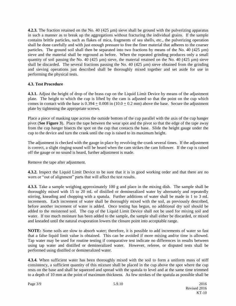
Page 3/9 5.9.10 2016
Revised 2016
KT-10
4.2.3. The fraction retained on the No. 40 (425 µm) sieve shall be ground with the pulverizing apparatus
in such a manner as to break up the aggregations without fracturing the individual grains. If the sample
contains brittle particles, such as flakes of mica, fragments of sea shells, etc., the pulverizing operation
shall be done carefully and with just enough pressure to free the finer material that adheres to the coarser
particles. The ground soil shall then be separated into two fractions by means of the No. 40 (425 µm)
sieve and the material shall be reground as before. When the repeated grinding produces only a small
quantity of soil passing the No. 40 (425 µm) sieve, the material retained on the No. 40 (425 µm) sieve
shall be discarded. The several fractions passing the No. 40 (425 µm) sieve obtained from the grinding
and sieving operations just described shall be thoroughly mixed together and set aside for use in
performing the physical tests.
4.3. Test Procedure
4.3.1. Adjust the height of drop of the brass cup on the Liquid Limit Device by means of the adjustment
plate. The height to which the cup is lifted by the cam is adjusted so that the point on the cup which
comes in contact with the base is 0.394 + 0.008 in (10.0 + 0.2 mm) above the base. Secure the adjustment
plate by tightening the appropriate screws.
Place a piece of masking tape across the outside bottom of the cup parallel with the axis of the cup hanger
pivot (See Figure 3). Place the tape between the wear spot and the pivot so that the edge of the tape away
from the cup hanger bisects the spot on the cup that contacts the base. Slide the height gauge under the
cup to the device and turn the crank until the cup is raised to its maximum height.
The adjustment is checked with the gauge in place by revolving the crank several times. If the adjustment
is correct, a slight ringing sound will be heard when the cam strikes the cam follower. If the cup is raised
off the gauge or no sound is heard, further adjustment is made.
Remove the tape after adjustment.
4.3.2. Inspect the Liquid Limit Device to be sure that it is in good working order and that there are no
worn or “out of alignment” parts that will affect the test results.
4.3.3. Take a sample weighing approximately 100 g and place in the mixing dish. The sample shall be
thoroughly mixed with 15 to 20 mL of distilled or demineralized water by alternately and repeatedly
stirring, kneading and chopping with a spatula. Further additions of water shall be made in 1 to 3 mL
increments. Each increment of water shall be thoroughly mixed with the soil, as previously described,
before another increment of water is added. Once testing has begun, no additional dry soil should be
added to the moistened soil. The cup of the Liquid Limit Device shall not be used for mixing soil and
water. If too much moisture has been added to the sample, the sample shall either be discarded, or mixed
and kneaded until the natural evaporation lowers the closure point into acceptable range.
NOTE: Some soils are slow to absorb water; therefore, it is possible to add increments of water so fast
that a false liquid limit value is obtained. This can be avoided if more mixing and/or time is allowed.
Tap water may be used for routine testing if comparative test indicate no differences in results between
using tap water and distilled or demineralized water. However, referee, or disputed tests shall be
performed using distilled or demineralized water.
4.3.4. When sufficient water has been thoroughly mixed with the soil to form a uniform mass of stiff
consistency, a sufficient quantity of this mixture shall be placed in the cup above the spot where the cup
rests on the base and shall be squeezed and spread with the spatula to level and at the same time trimmed
to a depth of 10 mm at the point of maximum thickness. As few strokes of the spatula as possible shall be

Page 4/9 5.9.10 2016
Revised 2016
KT-10
used, care being take to prevent the entrapment of air bubbles within the mass. The excess soil shall be
returned to the mixing dish. The soil in the cup of the device shall be divided by a firm stroke of the
grooving tool along the diameter through the centerline of the cam follower so that a clean sharp groove
of proper dimensions will be formed. To avoid tearing the sides of the groove or slipping of the soil cake
on the cup, up to six strokes from front to back or from back to front counting as one stroke shall be
permitted. The depth of the groove should be increased with each stroke and only the last stroke should
scrape the bottom of the cup.
4.3.5. The cup containing the sample prepared as described in Section 4.3.4 of this test method, shall be
lifted and dropped by turning the crank at the rate of approximately two revolutions per second until the
two sides of the sample come in contact at the bottom of the groove along a distance of about 0.5 in (13
mm). The number of shocks required to close the groove this distance shall be recorded. The base of the
machine shall not be held with the free hand while the crank is turned.
NOTE: Some soils tend to slide on the surface of the cup instead of flowing. If this occurs, more water
should be added to the sample and remixed, then the soil-water mixture placed in the cup, a groove cut
with grooving tool and Section 4.3.5 repeated. If the soil continues to slide on the cup at a lesser number
of blows than 25, the test is not applicable and a note should be made that the liquid limit could not be
determined.
4.3.6. A slice of soil approximately the width of the spatula, extending from the edge to edge of the soil
cake at right angles to the groove and including that portion of the groove in which the soil flowed
together, shall be removed and placed in suitable container. Record the sample mass to the nearest 0.01 g.
The soil in the container shall be dried in accordance with KT-11 to determine the moisture content. The
use of a lid for the container as stated in KT-11 is required. Record the results.
4.3.7. The soil remaining in the cup shall be transferred to the mixing dish. The cup and grooving tool
shall be washed and dried in preparation for the next trial.
4.3.8. The foregoing operations shall be repeated for at least two additional portions of the sample to
which sufficient water has been added to bring the soil to a more fluid condition. The object of this
procedure is to obtain samples of such consistency that at least one determination will be made in each of
the following ranges of shocks: 25-35, 20-30, 15-25. The range of the three determinations shall be at
least 10 shocks.
5. CALCULATIONS
5.1. Calculate the moisture content of the sample as follows:
Moisture Content = 100 X (A-C)
(C-B)
Where: A= Mass of wet soil and container, g
B= Mass of container, g
C= Mass of dry soil and container, g
5.1.1. Record the moisture content to the nearest 0.1%.
5.2. A “Flow Curve” representing relation between moisture content and corresponding number of shocks
shall be plotted on a semi-logarithmic graph with the moisture contents as abscissa on the arithmetical
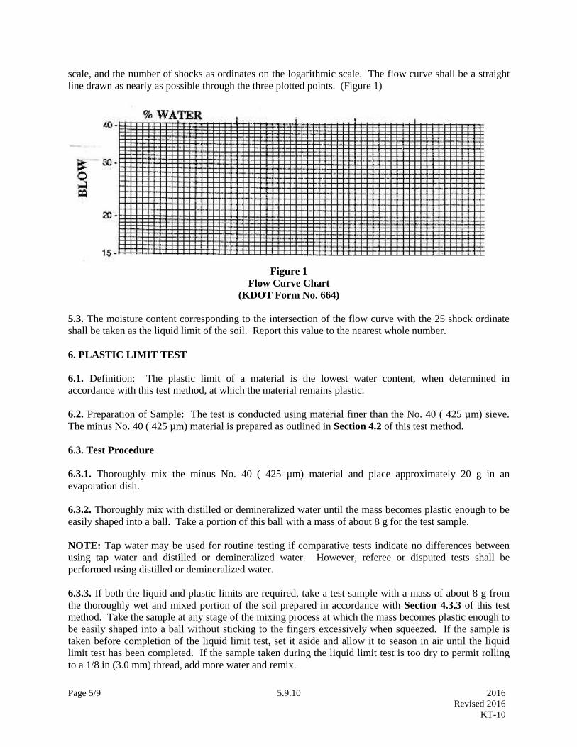
Page 5/9 5.9.10 2016
Revised 2016
KT-10
scale, and the number of shocks as ordinates on the logarithmic scale. The flow curve shall be a straight
line drawn as nearly as possible through the three plotted points. (Figure 1)
Figure 1
Flow Curve Chart
(KDOT Form No. 664)
5.3. The moisture content corresponding to the intersection of the flow curve with the 25 shock ordinate
shall be taken as the liquid limit of the soil. Report this value to the nearest whole number.
6. PLASTIC LIMIT TEST
6.1. Definition: The plastic limit of a material is the lowest water content, when determined in
accordance with this test method, at which the material remains plastic.
6.2. Preparation of Sample: The test is conducted using material finer than the No. 40 ( 425 µm) sieve.
The minus No. 40 ( 425 µm) material is prepared as outlined in Section 4.2 of this test method.
6.3. Test Procedure
6.3.1. Thoroughly mix the minus No. 40 ( 425 µm) material and place approximately 20 g in an
evaporation dish.
6.3.2. Thoroughly mix with distilled or demineralized water until the mass becomes plastic enough to be
easily shaped into a ball. Take a portion of this ball with a mass of about 8 g for the test sample.
NOTE: Tap water may be used for routine testing if comparative tests indicate no differences between
using tap water and distilled or demineralized water. However, referee or disputed tests shall be
performed using distilled or demineralized water.
6.3.3. If both the liquid and plastic limits are required, take a test sample with a mass of about 8 g from
the thoroughly wet and mixed portion of the soil prepared in accordance with Section 4.3.3 of this test
method. Take the sample at any stage of the mixing process at which the mass becomes plastic enough to
be easily shaped into a ball without sticking to the fingers excessively when squeezed. If the sample is
taken before completion of the liquid limit test, set it aside and allow it to season in air until the liquid
limit test has been completed. If the sample taken during the liquid limit test is too dry to permit rolling
to a 1/8 in (3.0 mm) thread, add more water and remix.

Page 6/9 5.9.10 2016
Revised 2016
KT-10
6.3.4. Select 1.5 to 2.0 g of soil taken in Section 6.3.3 of this test method. Form into an ellipsoidal mass.
6.3.5. Roll this mass between the fingers and the palm of the hand and a ground glass plate with just
sufficient pressure to roll the mass into a thread of uniform diameter throughout its length. The rate of
rolling shall be between 80 and 90 strokes per minute, counting a stroke as one complete motion of the
hand forward and back to the starting position again. Reduce the diameter of the thread to 1/8 in (3.0
mm), taking no more than 2 min. Quickly squeeze and reform the thread into an ellipsoidal shaped mass
and re-roll. Continue this alternate reforming and re-rolling to a thread 1/8 in (3.0 mm) in diameter,
gathering together, kneading and re-rolling, until the thread crumbles under the pressure required for
rolling and the material can no longer be rolled into a thread. The crumbling may occur when the thread
is greater than 1/8 in (3.0 mm) in diameter. This shall be considered a satisfactory end point, provided the
material has been rolled to a thread of 1/8 in (3.0 mm) during the previous rolling. The crumbling will
manifest itself differently with various types of material. Some materials fall apart in numerous small
aggregations of particles; others may form an outside tubular layer that starts splitting at both ends.
Splitting progresses toward the middle, and finally, the thread falls apart in many small platy particles. It
is not practical to define crumbling to an exact degree since, as stated above, crumbling will manifest
itself differently for different materials. At no time shall the operator attempt to produce failure at exactly
1/8 in (3.0 mm) diameter by allowing the thread to reach 1/8 in (3.0 mm), then reducing the rate of rolling
or the hand pressure or both, and continuing the rolling without further deformation until the thread falls
apart. It is permissible, however, to reduce the total amount of deformation for feebly plastic soils by
making the initial diameter of the ellipsoidal shaped mass nearer to the required 1/8 in (3.0 mm) final
diameter.
6.3.6. Place the crumbled thread in a watch glass or other suitable container of known mass and close to
prevent evaporation loss. Repeat steps 6.3.4. to 6.3.6. untill the entire 8 gram sample has been tested.
6.3.7. Gather the portions of the crumbled soil together and place in a suitable tared container. Record the
sample mass to the nearest 0.01 g. The soil in the container shall be dried in accordance with KT-11
Sections 3 through 5, to determine the moisture content. The use of a lid for the container as stated in
KT-11 is required. Record the results.
6.4. Alternate procedure using the Plastic Limit Device
6.4.1. Attach smooth unglazed paper to both the bottom fixed plate and the top of the Plastic Limit
Device.
6.4.2. Split the 8 g. test sample taken in Section 6.3.3 and 6.3.4 of this test method into four or five
masses of 1.5 to 2.0 g each. Squeeze into an ellipsoidal-shape and place two to three masses on the
bottom plate. Place the top plate in contact with the soil masses. Simaltaneously with a slight downward
force, apply a back-and-forth rolling motion with the top plate until the top plate comes into contact with
the 3.2 mm side rails, within two minutes. Do not allow the soil thread to come into contact with the side
rails.
6.4.3. Continue the test as outlined in Sections 6.3.5, 6.3.6, and 6.3.7 of this test method.
7. CALCULATIONS
7.1. Calculate the moisture content of the sample at its plastic limit as follows:

Page 7/9 5.9.10 2016
Revised 2016
KT-10
Plastic Limit =100 × (A -C)
(C-B)
Where: A= Mass of wet soil and container, g
B= Mass of container, g
C= Mass of dry soil and container, g
7.2. Record all masses to the nearest 0.01 g. Calculate and record the percentage of moisture to the 0.1%,
report the percentage of moisture to the nearest whole percent.
8. PLASTIC INDEX
8.1. Definition: The plastic index of a material is the numerical difference between the liquid limit and
the plastic limit.
8.2. Calculations: Calculate the plastic index as follows, or calculate on KDOT Form 663.
Plastic Index = Liquid Limit (as recorded) – Plastic Limit (as recorded).
8.3. Reporting: Report the plastic index and liquid limit (when required) to the nearest whole number.
NOTE: When testing extremely sandy samples, it is permissible to conduct the plastic limit test first. If
the plastic limit cannot be determined, report the plastic index as NP (i.e. nonplastic). If the plastic limit
is equal to or greater than the liquid limit, report the plastic index as NP.
9. WET PREPARATION (FOR AGGREGATE MATERIAL ONLY)
9.1. The following “wash” method of preparation shall be used for all types of aggregates, binder soil and
mineral fillers. However, in the case of a mineral filler which all passes a No. 40 (425 µm) sieve, the
washing process may be waived and the sample prepared for testing by reducing it to particle size using
the pulverizing apparatus.
9.2.1. Dry the material to a moisture condition at which it can be pulverized and dry-screened without
sticking or clogging the screens.
9.2.2. Dry-screen the material over a No. 40 (425 µm) sieve to remove as much of the portion passing the
No. 40 (425 µm) sieve as possible before washing. Several larger sieves may be used in this process to
keep part of the load off the No. 40 (425 µm) sieve. This initial dry-screening is very important as it
helps to reduce the time and water required for the washing process which follows. Set aside the minus
No. 40 (425 µm) material obtained in this manner for recombination with material obtained by later steps.
9.2.3. Place the material retained on the No. 40 (425 µm) sieve in a pan, cover with water and soak for a
minimum of 30 minutes.
9.2.4. Following the soaking period, wash the material, using not less than four applications of wash
water, including the soaking water. Each application of water must cover the entire sample. The washing
for each application is accomplished by a “sloshing” action of the pan. Should an appreciable amount of
plastic material remain with the sample after four applications of water, use additional applications
accompanied by more vigorous agitation of the material. Decant each application of the wash water
through a No. 40 (425 µm) sieve, saving all of the wash water and material.

Page 8/9 5.9.10 2016
Revised 2016
KT-10
9.2.5. Evaporate the water from the washed plus No. 40 (425 µm) material and from the material washed
through the No. 40 (425 µm) sieve using an oven with temperature settings not to exceed 140°F (60°C).
In most cases, after a short period of heating, the particles in suspension will settle out so that the clear
water at the top of the pan may be siphoned off to reduce the drying time.
9.2.6. If the material in the retained wash water becomes caked during the drying process, break it down
to pass the No. 40 (425 µm) sieve with the pulverizing apparatus. This pulverizing shall be done, insofar
as possible, in a manner which will not change the characteristics of the material.
9.2.7. Dry-screen the dried material, retained on the No. 40 (425 µm) sieve during the washing process,
over a No. 40 (425 µm) sieve after which the material retained on the sieve may be discarded.
9.2.8. Recombine and thoroughly mix the minus No. 40 (425 µm) material obtained by the initial dry-
screening, that obtained by washing and that obtained by re-screening the coarse material after washing.
The sample thus prepared is ready for testing.
Figure 2
Plastic Limit Device

Page 9/9 5.9.10 2016
Revised 2016
KT-10
Figure 3
Brass Cup Calibration
Wear spot
Tape
Cup hanger pivot

Page 1/12 5.9.14 2016
Revised 2015
KT-14
5.9.14 (5.16.14) MARSHALL TESTS OF BITUMINOUS MIXES
(Kansas Test Method KT-14)
a. SCOPE
This method of test covers the procedures for testing bituminous
mixes to determine:
a.1. Optimum Asphalt Content.
a.2. Density Characteristics, including voids content.
a.3. Stability Characteristics, including resistance to plastic
flow and flow properties.
a.4. This method is limited to mixes containing asphalt cement
and containing aggregate having a maximum size of 25 mm (1 in).
KT-14 reflects testing procedures found in AASHTO T 245 and T
269.
b. REFERENCED DOCUMENTS
b.1. KT-15; Bulk Specific Gravity and Unit Weight of Compacted
Bituminous Mixtures
b.2. KT-57; Determination of Asphalt Content and Gradation of Hot
Mix Asphalt Concrete by the Ignition Method
b.3. KT-58; Method for Preparing and Determining the Density of
Hot Mix Asphalt (HMA) Specimens by Means of the
Superpave Gyratory Compactor
b.4. AASHTO M 231; Balances Used in Testing of Materials
b.5. AASHTO T 245; Resistance to Plastic Flow of Bituminous
Mixtures Using Marshall Apparatus
b.6. AASHTO T 269; Percent Air Voids in Compacted Dense and Open
Bituminous Paving Mixtures
b.7. ASTM D 1559; Test Method for Resistance to Plastic Flow of
Bituminous Mixtures Using Marshall Apparatus

Page 2/12 5.9.14 2016
Revised 2015
KT-14
c. APPARATUS
c.1. Specimen Mold Assembly: A cylindrical mold having an inside
diameter of 101.6 + 0.25 mm (4.000 + 0.010 in)1 and a length of
approximately 90 mm (3 7/16 in). The mold is open at each end
and is equipped with a removable collar and a base plate about 15
mm (9/16 in) in thickness. A minimum of three molds is
recommended.
c.2. Compaction Hammer: The compaction hammer consists of a
hammer having a flat circular tamping face, 98.4 mm (3 7/8 in) in
diameter, and appropriate extension rod with handle which acts as
guide for a free falling weight. The weight shall weigh 4,536 +
18 g (10 + 0.04 lb) and have a free fall of 457.2 + 2.5 mm (18 +
0.1 in). The hammer may be operated manually or be driven with a
motor. Two compaction hammers are recommended.
c.3. Compaction Pedestal: The compaction pedestal is a wood
block approximately 300 by 300 by 450 mm (12 by 12 by 18 in). A
300 by 300 by 25 mm (12 by 12 by 1 in) steel plate is securely
fastened to the top of the block. The pedestal is set on and
securely fastened to a solid concrete slab with the vertical axis
plumb and the top level.
c.4. Specimen Mold Holder: The specimen mold holder has a semi-
circular base and a flanged top to hold the specimen mold in
place during the compaction process. Any equivalent hold down
device which performs the same function is satisfactory.
c.5. Specimen Extruder: An extruder for the removal of the
specimens from the mold is recommended. The unit may consist of
a steel frame to hold the mold, a hydraulic jack and a steel disc
approximately 13 mm (1/2 in) thick and 100 mm (3.9 in) in
diameter.
c.6. Testing Assembly: This includes a breaking head, a load
measuring device and two flow meters, dial micrometers or an
automatic stability/flow recording device. The testing assembly
shall be calibrated at intervals not exceeding two years.
c.6.a. Breaking Head: The breaking head consists of two
accurately machined cylindrical segments having an inside
radius of 50 mm (2 in). The lower segment is mounted on a
base having two perpendicular guide rods or posts extending
upward. Sleeves in the upper segment are positioned to guide
1 AASHTO T 245 requires the compaction molds to be 101.6 + 0.13 mm (4.000+ 0.005 in).

Page 3/12 5.9.14 2016
Revised 2015
KT-14
the two segments together without appreciable binding or loose
motion on the guide rods.
c.6.b. Flow Meters: Two flow meters graduated in 0.25 mm (.01
in) increments and conforming to the details set forth in
ASTM D 1559 or two micrometer dials graduated in 0.025 mm
(0.001 in) increments are used to measure plastic flow.
Instead of the flowmeter, a micrometer dial or stress-strain
recorder graduated in 0.25 mm (0.01 in) divisions.
c.6.c. Loading Device: The loading device may be either a screw
jack or a hydraulic system, manually or motor operated to
produce a constant vertical movement of 50 + 2 mm/min (2 + 0.1
in/min) during application of load.
c.6.d. Load Measuring Device:
c.6.d.1. Proving ring assembly consisting of a 20 kN (5,000 lb)
capacity proving ring, sensitive to 44.5 N (10 lb) up to 4.45
kN (1,000 lb) and to 111.2 N (25 lb) above 4.45 kN (1,000 lb).
The proving ring is equipped with a micrometer dial graduated
in 0.0025 mm (0.0001 in) increments.
The upper portion of the ring is attached to the testing frame
and the lower portion transmits the load to the breaking head.
c.6.d.2. In lieu of the proving ring assembly, any suitable load
measuring device may be used providing the capacity and
sensitivity meet the above requirements.
c.7. Heating Equipment: Ovens or hot plates for heating
aggregates, bituminous material, specimen molds, compaction
hammers and other associated items required for mixing and
molding. It is recommended that, when possible all heating units
be thermostatically controlled to maintain the required
temperature within + 2.8oC (+ 5
oF). Suitable shields, thick steel
plates or pans of sand shall be used on the surfaces of hot
plates to minimize localized overheating.
c.8. Mixing Apparatus: Mechanical mixing is recommended. Any
type of mechanical mixer may be used provided it will produce a
well coated, homogeneous mixture of the required amount in the
allowable time and further that the mixing paddle or whip does
not fracture or pulverize aggregate fractions during the mixing
process. The bowl employed with the mixer shall be of such a
nature that essentially all of the batch can be removed. More
than one mixing bowl is recommended unless the mixer is equipped

Page 4/12 5.9.14 2016
Revised 2015
KT-14
with a heating jacket to keep the bowl heated during the mixing
process.
c.9. Water Bath: The water bath shall be approximately 140 mm
(5 1/2 in) deep and shall be thermostatically controlled so as to
maintain the bath at 60 + 1oC (140 + 2
oF). The tank shall have a
perforated false bottom or be equipped with a shelf for
adequately supporting specimens approximately 50 mm (2 in) above
the bottom of the bath.
c.10. Miscellaneous Equipment:
c.10.a. Containers for heating aggregates, flat-bottom metal pans
or other suitable containers.
c.10.b. Containers for heating bituminous material, beakers,
ointment cans, pouring pots, etc. may be used.
c.10.c. Mixing tool, steel towel or spatula, for spading and hand
mixing.
c.10.d. Thermometers for determining temperatures of aggregate,
bitumen and bituminous mixtures. Armored glass or dial type
with metal stem thermometers may be used. A range of at least
10 to 200oC (50 to 400
oF) with a sensitivity of 2.8
oC (5
oF) is
required.
c.10.e. Thermometer for water bath sensitivity to 0.1oC (0.2oF).
c.10.f. The balance shall conform to the requirements of AASHTO M
231 for the class of general purpose balance required for the
principal sample mass of the sample being tested.
c.10.g. Large Spoon, for cleaning of mixing bowl or placing
mixture in mold cylinders.
c.10.h. Specimen height measuring device.
c.10.i. Gloves for handling hot equipment.
c.10.j. 100 mm (4 in) dia. paper discs.

Page 5/12 5.9.14 2016
Revised 2015
KT-14
d. DETERMINATION OF MIXING AND COMPACTING TEMPERATURE
d.1. The temperatures to which the asphalt cement must be heated
to produce a viscosity of 170 + 20 cSt (85 + 10 SFS) shall be the
mixing temperature.
d.2. The temperature to which the asphalt cement must be heated
to produce a viscosity of 280 + 30 cSt (135 + 15 SFS) shall be
the compacting temperature.
e. SAMPLE PREPARATION
e.1. Hot Plant Mixes with Asphalt: Mix the sample of mixed
material thoroughly and split out not less then three increments
weighing approximately 1,200 g for a 100 mm (4 in) diameter plug.
Bring the increments to within the limits of the compacting
temperature determined in d.2. prior to compacting. See KT-57 d.
for method of quartering to obtain proper sized sample.
e.2. Laboratory Prepared Mixes: If using hydrated lime as an
antistripping agent, then refer to the attached Addendum.
e.2.a. Number of Specimens: It is recommended that each aggregate
combination be tested at six different asphalt contents, in
1/2 percent increments. At least three specimens are prepared
for each percentage of asphalt. Prepare one extra aggregate
and asphalt sample to be mixed first and then thrown away.
This sample is to "butter" the mixing bowl and paddle and thus
reduce material loss when mixing the test specimens.
e.2.b. Preparation of Virgin Aggregates: Dry individual
aggregates to constant mass at 105 to 110oC (221 to 230
oF).
Separate the individual aggregates by dry screening into
desired fractions. The following size fractions2 are
recommended as a minimum:
25.0 to 19.0 mm (1 to 3/4 in) 4.75 to 2.36 mm (No.4 to No.8)
19.0 to 12.5 mm (3/4 to 1/2 in) 2.36 to 1.18 mm (No.8 to No.16)
12.5 to 9.5 mm (1/2 to 3/8 in) Passing 1.18 mm (Passing No.16)
9.5 to 4.75 mm (3/8 in to No.4)
e.2.c. Preparation of Reclaimed Material: Place the reclaimed
material in a 50 to 80oC (125 to 175
oF) draft oven for 1 1/2 to
2 hours, to soften. Transfer the materials to the mixing bowl
and mix for two minutes in order to breakdown the reclaimed
material to the recommended sizes. (Mixer will mix
2 AASHTO T 245 3.2 fraction recommendations use fewer sieve sizes.

Page 6/12 5.9.14 2016
Revised 2015
KT-14
approximately 3,500 g.) Other methods of breakdown are
acceptable provided they do not fracture aggregates or lose an
excessive amount of material in the process. Separate the
reclaimed material into desired fractions by screening, when
cool enough to screen. The following size fractions are
recommended:
19.0 to 12.5 mm (3/4 to 1/2 in) 4.75 to 2.36 mm (No.4 to No.8)
12.5 to 9.5 mm (1/2 to 3/8 in) Passing 2.36 mm (Passing No.8)
9.5 to 4.75 mm (3/8 in to No.4)
Weigh each fraction and record percentage of total sample.
e.2.d. Preparation of Mixes: Combine the individual aggregates
or reclaimed material and virgin aggregates by weighing out in
a separate pan for each test specimen, proportionate amounts
of each size fraction for each individual aggregate to produce
the desired combined aggregate with a batch mass of
approximately 1,125 g. This should be sufficient to produce a
compacted specimen 64 + 3 mm (2.5 + 1/8 in) thick3. Adjust the
mass of the batch as needed to produce compacted specimens of
64 + 3 mm (2.5 + 1/8 in) thickness.
Heat the aggregate and asphalt within the limits of mixing
temperature determined in d.1. Charge the mixing bowl with
the heated aggregate and form a crater in the top. Add the
required amount of asphalt and mix the aggregate and asphalt
until thoroughly coated, at least 2 minutes. Care should be
taken to keep all of the sample in the mixing bowl during this
process.
Place the mix in a 135oC (275
oF) oven and age
4 the material for
2 hours as outlined in KT-58 g.5. At the end of the aging
time place the mix in an oven set at the compaction
temperature or reset the 135oC (275
oF) oven temperature to
reflect the compaction temperature. Allow the mix to adjust
to the new temperature prior to removing for compaction.
e.2.e. Compaction of Specimens: Prior to the addition of the
asphalt to the batches, thoroughly clean the specimen mold
assembly and the face of the compaction hammer and heat the
mold assembly and hammer in boiling water, in an oven or on a
hot plate, to a temperature between 90 and 175oC (200 and
3 AASHTO T 245 3.4.2 requires compaction height to be 63.5 + 1.27 mm (2.5 + 0.05 in). 4 The aging process reflects information found in the proposed AASHTO R30-02 Standard Practice for Mixture
Conditioning of Hot-Mix Asphalt (HMA).

Page 7/12 5.9.14 2016
Revised 2015
KT-14
350oF). Assemble the mold, base plate and collar and place a
paper disc cut to size in the bottom of the mold.
Place the entire hot batch of aggregate-asphalt mixture in the
mold, spade vigorously with a heated spatula or trowel 15
times around the perimeter and 10 times over the interior of
the mold. Smooth the surface of the mix to a slightly rounded
shape5. The temperature of the mix just prior to compaction
shall be within the limits determined in d.2. Place a paper
disc on top of the mix.
Place the mold assembly, including the collar, on the
pedestal, fasten securely with the mold holder and apply 50 or
75 blowsa with the compaction hammer. Each blow must have the
prescribed free fall of 457 mm (18 in) with the axis of the
compaction hammer held perpendicular to the base of the mold
assembly during the compaction process. Remove the base plate
and collar, and reverse and reassemble the mold. Apply the
specified number of blows to the reversed specimen. After
compaction, remove the mold assembly from the pedestal. Place
the mold into the extractor and pop the plug loose from the
mold. Permit the plug to cool in this state until the next
plug has been processed. Extrude the initial plug out of the
mold and pop the next plug loose. Carefully transfer the
extruded plug to a smooth, flat surface and allow it to stand
until the plug reaches room temperature6.
Note a: Traffic volume in the Design Lane determines the
number of blows. (See subsection 5.18.02 a.5.a. for traffic
volume criteria.)
e.2.f. Thickness of Specimen: Measure the specimen thickness to
the nearest 0.025 mm (0.001 in). If the specimen thickness is
less than 60 mm (2.375 in) or more than 67 mm (2.625 in),
discard it and mold a replacement having a thickness within
these limits.
e.2.g. Determination of Specific Gravity and Unit Weight:
Determine the specific gravity and unit weight by the
appropriate method as outlined in KT-15.
e.2.h. After determining the specific gravity for all of the
specimens, proceed to f.
5 AASHTO T 245 3.5.1 requires the removal of the collar , then smoothing the surface of the mix. With the
aggregates used by KDOT the material may overflow the mold. 6 AASHTO T 245 3.5.2 requires the plug to stand overnight at room temperature.
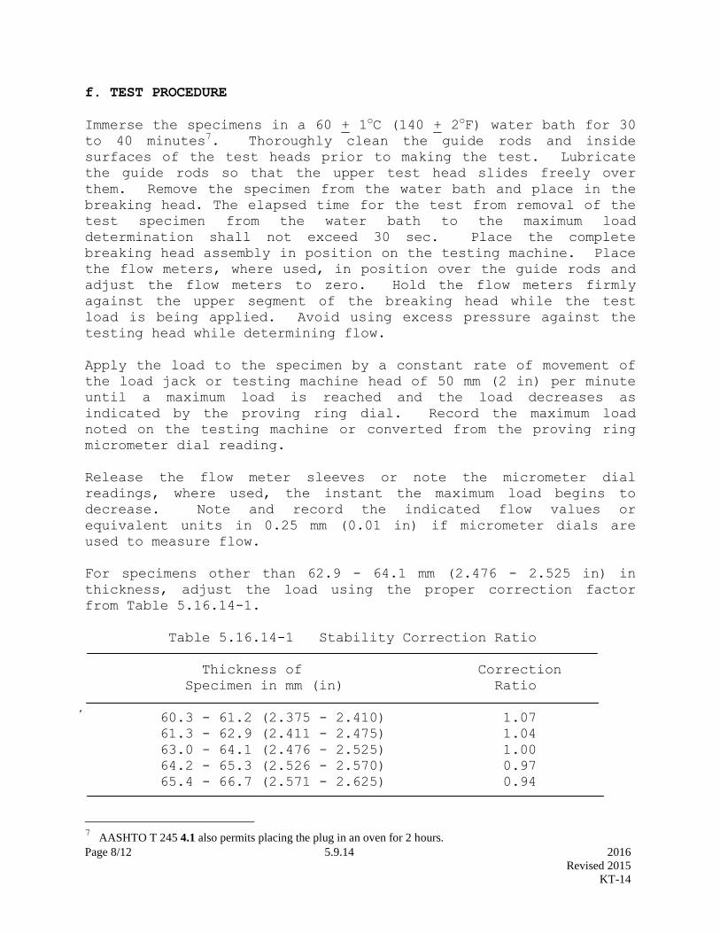
Page 8/12 5.9.14 2016
Revised 2015
KT-14
f. TEST PROCEDURE
Immerse the specimens in a 60 + 1oC (140 + 2
oF) water bath for 30
to 40 minutes7. Thoroughly clean the guide rods and inside
surfaces of the test heads prior to making the test. Lubricate
the guide rods so that the upper test head slides freely over
them. Remove the specimen from the water bath and place in the
breaking head. The elapsed time for the test from removal of the
test specimen from the water bath to the maximum load
determination shall not exceed 30 sec. Place the complete
breaking head assembly in position on the testing machine. Place
the flow meters, where used, in position over the guide rods and
adjust the flow meters to zero. Hold the flow meters firmly
against the upper segment of the breaking head while the test
load is being applied. Avoid using excess pressure against the
testing head while determining flow.
Apply the load to the specimen by a constant rate of movement of
the load jack or testing machine head of 50 mm (2 in) per minute
until a maximum load is reached and the load decreases as
indicated by the proving ring dial. Record the maximum load
noted on the testing machine or converted from the proving ring
micrometer dial reading.
Release the flow meter sleeves or note the micrometer dial
readings, where used, the instant the maximum load begins to
decrease. Note and record the indicated flow values or
equivalent units in 0.25 mm (0.01 in) if micrometer dials are
used to measure flow.
For specimens other than 62.9 - 64.1 mm (2.476 - 2.525 in) in
thickness, adjust the load using the proper correction factor
from Table 5.16.14-1.
Table 5.16.14-1 Stability Correction Ratio
Thickness of Correction
Specimen in mm (in) Ratio
60.3 - 61.2 (2.375 - 2.410) 1.07
61.3 - 62.9 (2.411 - 2.475) 1.04
63.0 - 64.1 (2.476 - 2.525) 1.00
64.2 - 65.3 (2.526 - 2.570) 0.97
65.4 - 66.7 (2.571 - 2.625) 0.94
7 AASHTO T 245 4.1 also permits placing the plug in an oven for 2 hours.

Page 9/12 5.9.14 2016
Revised 2015
KT-14
NOTE: The measured stability of a specimen multiplied by
the ratio for the thickness of the specimen equals the
corrected stability for a 63.5 mm (2 1/2 in) specimen.
g. EVALUATION OF SPECIFIC GRAVITY AND STABILITY DATA:
g.1. Specific Gravity of Molded Specimens:
g.1.a. If the difference between the specific gravity of a single
specimen in a set of three specimens and the average of the
set is greater than 0.025, discard the entire set and mold a
new set.
g.1.b. If the difference between the specific gravity of a single
specimen in a set of three specimens and the average of the
set is greater than 0.014 and not greater than 0.025, discard
the results of the single specimen and use the results of the
tests on the remaining two specimens to compute the average
specific gravity of the set.
g.1.c. If the difference between the specific gravity of a single
specimen in a set of three specimens and the average specific
gravity of the set in question is not greater than 0.014, the
specific gravity of the specimen is acceptable and may be used
to determine the average specific gravity.
g.2. Stability of Molded Specimens:
If the difference between the stability of a specimen and the
average stability of the set of three specimens is not greater
than the CV1 values shown in Table 5.16.14-2 the specimen is
acceptable for use in determining the average stability of the
set.
If this difference is greater the CV1 value but not greater than
the CV2 values, the specimen will be eliminated in the
calculation of the average stability. Not less than two
specimens will be used when determining the set average
stability.
If the difference between the stability of any specimen of a set
and the average stability of the set is greater then CV2 values
shown in Table 5.16.14-2, the entire set will be discarded and
another set obtained.
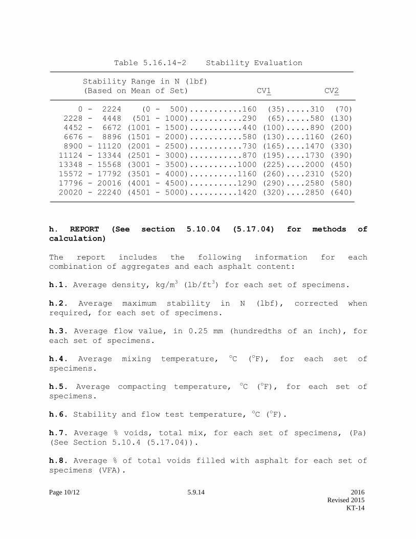
Page 10/12 5.9.14 2016
Revised 2015
KT-14
Table 5.16.14-2 Stability Evaluation
Stability Range in N (lbf)
(Based on Mean of Set) CV1 CV2
0 - 2224 (0 - 500)...........160 (35).....310 (70)
2228 - 4448 (501 - 1000)...........290 (65).....580 (130)
4452 - 6672 (1001 - 1500)...........440 (100).....890 (200)
6676 - 8896 (1501 - 2000)...........580 (130)....1160 (260)
8900 - 11120 (2001 - 2500)...........730 (165)....1470 (330)
11124 - 13344 (2501 - 3000)...........870 (195)....1730 (390)
13348 - 15568 (3001 - 3500)..........1000 (225)....2000 (450)
15572 - 17792 (3501 - 4000)..........1160 (260)....2310 (520)
17796 - 20016 (4001 - 4500)..........1290 (290)....2580 (580)
20020 - 22240 (4501 - 5000)..........1420 (320)....2850 (640)
h. REPORT (See section 5.10.04 (5.17.04) for methods of
calculation)
The report includes the following information for each
combination of aggregates and each asphalt content:
h.1. Average density, kg/m3 (lb/ft3) for each set of specimens.
h.2. Average maximum stability in N (lbf), corrected when
required, for each set of specimens.
h.3. Average flow value, in 0.25 mm (hundredths of an inch), for
each set of specimens.
h.4. Average mixing temperature, oC (
oF), for each set of
specimens.
h.5. Average compacting temperature, oC (
oF), for each set of
specimens.
h.6. Stability and flow test temperature, oC (oF).
h.7. Average % voids, total mix, for each set of specimens, (Pa)
(See Section 5.10.4 (5.17.04)).
h.8. Average % of total voids filled with asphalt for each set of
specimens (VFA).

Page 11/12 5.9.14 2016
Revised 2015
KT-14
h.9. Average % of voids in aggregate only (VMA).
h.10. Maximum percentage of asphalt allowed for high temperature
protection (P'b).
h.11. Recommended asphalt percentage for initial plant operation.
h.12. Bearing Capacity.
h.13. Theoretical Maximum Specific Gravity.
Show values for h.1., h.2., h.7., h.8., h.9., h.12., and h.13.
using KDOT Form 701.

Page 12/12 5.9.14 2016
Revised 2015
KT-14
ADDENDUM TO KT-14
FOR INCLUDING LIME AS AN ANTISTRIPPING AGENT
The following information provides KT-14 with steps to
incorporate hydrated lime as an antistripping agent.
Delete e.2.d. and replace with the following:
e.2.d. Preparation of Mixes: Combine the virgin aggregates by
weighing in a separate pan for each test specimen,
proportionate amounts of each size fraction for each
individual aggregate to produce the desired combined aggregate
with a batch mass of approximately 1,125 g. Include the
hydrated lime mass required to meet the specified percent of
lime for the project as part of the total batch mass. The
total aggregate mass should include lime, virgin aggregate,
and reclaimed material (if applicable). This should be
sufficient to produce a compacted specimen 64 + 3 mm (2.5 +
1/8 in) thick. Adjust the mass of the batch as needed to
produce compacted specimens of 64 + 3 mm (2.5 + 1/8 in)
thickness.
e.2.d.1. Determine the SSD for the combined aggregate gradation.
Add three percent of moisture to the percent moisture required
to reach the SSD condition of the combined aggregate.
e.2.d.2. Place the combined virgin aggregate and hydrated lime in
a mixing bowl. Carefully mix until the hydrated lime is
combined with the aggregate. Add the appropriate water
content, as determined in e.2.d.1., and thoroughly mix.
e.2.d.3. Oven dry the aggregate mix at approximately 110oC (230oF)
to a constant mass.
e.2.d.4. Combine the virgin aggregate material with the reclaimed
material, if applicable, and thoroughly mix. Heat the
combined aggregate and asphalt within limits of the mixing
temperature determined in d.1. Charge the mixing bowl with
the heated aggregate and form a crater in the top. Add the
required amount of asphalt and mix the aggregate and asphalt
until thoroughly coated, at least 2 minutes. Care should be
taken to keep all of the sample in the mixing bowl during this
process.

Page 1/6 5.9.15 2016
Revised 2016
KT-15
5.9.15 BULK SPECIFIC GRAVITY AND UNIT WEIGHT OF COMPACTED HOT MIX ASPHALT
(HMA) (Kansas Test Method KT-15)
1. SCOPE
This method of test covers the procedure for determining the bulk specific gravity of specimens of
compacted asphalt mixtures. The specimens may have been molded in the laboratory or cut or cored form
compacted pavements. KT-15 reflects testing procedures found in AASHTO T 166 and AASHTO T
331.
2. REFERENCED DOCUMENTS
2.1. Part V, 5.9.; Sampling and Test Methods Foreword
2.2. AASHTO T 166; Bulk Specific Gravity of Compacted Hot Mix Asphalt (HMA) Using Saturated
Surface – Dry Specimens
2.3. AASHTO T 331; Bulk Specific Gravity and Density of Compacted Hot Mix Asphalt (HMA) Using
Automatic Vacuum Sealing Method
3. APPARATUS
3.1. The balance shall conform to the requirements of Part V, 5.9; Sampling and Test Methods
Foreword, for the class of general purpose balance required for the principal sample mass of the sample
being tested.
3.2. Wire basket formed of No. 4 (4.75 mm) mesh hardware cloth, 1/4 in (6.3 mm) mesh or perforated
shelf or suitable bucket. The size shall be sufficient to fully support the specimen.
3.3. Container with overflow device, for immersing the wire basket, shelf or bucket in water and
maintaining a constant water level.
3.4. Measuring device to establish the physical dimensions of a specimen.
3.5. Vacuum chamber with a 1.25 h (0.93kW) pump capable of evacuating a sealed and enclosed chamber
to 29.5 in Hg vacuum (100 kPa vacuum) in less than 60 seconds. The chamber shall be large enough to
seal samples of 6 in (150 mm) wide by 14 in (350 mm) long by 6 in (150 mm) thick. The device shall
automatically seal the plastic bag and exhaust air back into the chamber in a controlled manner to ensure
proper conformance of the plastic to the asphalt specimen.
3.6. Plastic bags used with the vacuum device shall be one of the two following sizes. The smaller bags
shall have a minimum opening of 9.25 in (235 mm) and a maximum opening 10.25 in (260 mm). The
larger bags shall have a minimum opening of 14.75 in (275 mm) and a maximum opening of 15.5 in (294
mm).
3.7. Specimen sliding plate used within the vacuum chamber for reduction of friction on the plastic bags.

Page 2/6 5.9.15 2016
Revised 2016
KT-15
4. PROCEDURE
4.1. The bulk specific gravity of a compacted asphalt mix specimen is determined by computing the ratio
of its mass in air to its bulk volume. Procedure I is a rapid method which generally provides sufficient
accuracy for the routine testing of specimens with dense, impermeable surfaces. Procedure II corresponds
to AASHTO T 331 test method for Bulk Specific Gravity and Density of Compacted Hot Mix Asphalt
(HMA) Using Automatic Vacuum Sealing Method. Procedure III is a laboratory method which is used to
determine the bulk specific gravity of saturated specimens, and corresponds to AASHTO T 166, Method
A. This method is most suitable for testing specimens with slightly permeable surfaces in order to obtain
the water absorption. Procedure IV is a method which establishes the bulk specific gravity of specimens
which are composed of “open” mixes that typically display high porosity and permeability. In the event
of dispute, Procedure IV will take precedence over Procedures I & II. Marshall and Superpave design
specimens molded at the estimated “optimum” asphalt content will be subjected to Procedure III to
determine the water absorption (by volume). If the water absorption is equal to or greater than 2.0%,
Procedure II shall be used for both design and routine or field purposes.
4.1.1. Constant mass shall be defined as the mass at which further drying does not alter the mass by more
than 0.05%. Initially dry the specimen overnight by either placing in an oven at 125 + 5° F (52 + 3°C) or
by placing in front of a fan on an elevated wire rack and then weigh the next day at one-hour1 intervals.
4.1.2. Specimens are defined to be at room temperature when meeting the following procedure: Check
surface temperature. Let the specimen set for 5 minutes while at ambient air conditions (no flow of any
type should be flowing across the specimen). Recheck the surface temperature. The original check and
recheck must fall within 77 + 5°F (25 + 3°C) or the specimen temperature has not stabilized to room
temperature.
4.2. Procedure I
4.2.1. Weigh specimen at room temperature to the nearest 0.1 g after it has attained room temperature.
4.2.2. Place the specimen in the basket or bucket and determine it’s mass to the nearest 0.1 g while
immersed in water with a temperature of 77 + 2°F (25 + 1°C). The mass of the specimen in water shall
be determined as quickly as possible after the specimen is immersed. This method should not be used if
the specimen contains open or interconnecting voids.
4.3. Procedure II
4.3.1. Dry the specimen to constant mass and weigh it to the nearest 0.1g.
4.3.2. Cool the specimen to room temperature.
4.3.3. Select an appropriate size bag. For all 4 in (100 mm) diameter samples and samples with 6 in (150
mm) diameter and less than 2 in (50 mm) thickness, it is possible to use the bag with the smaller opening
size.
4.3.4. Place a bag inside the vacuum chamber on top of the sliding plate.
4.3.5. Gently open the bag and place the specimen in the plastic bag on top of the sliding plate, while
being careful not to handle the bag in such a manner that would create a puncture.
1 AASHTO T 166 and T 331 require a two-hour interval.
Page 3/6 5.9.15 2016
Revised 2016
KT-15
4.3.6. Allow the vacuum chamber to remove the air from the chamber and the plastic bag. The vacuum
chamber shall automatically seal the bag once the air is removed.
4.3.7. Exhaust air into the chamber until the chamber door opens indicating atmospheric pressure within
the chamber. The chamber door latch can be used to avoid automatic opening of the door after
completion of the test.
4.3.8. Remove the sealed specimen from the vacuum chamber. Handle the sealed specimen with extreme
care.
4.3.9. Weigh the sealed specimen in air to the nearest 0.1g.
4.3.10. Weigh the sealed specimen while immersed in water at 77 + 2°F (25 + 1°C) to the nearest 0.1 g.
Verify that no air bubbles are entrapped underneath the plastic bag material. This can be accomplished by
placing the sealed specimen in water with the plastic bag oriented in a vertical direction.
4.3.11. Reweigh the sealed specimen in air to the nearest 0.1 g.
4.4. Procedure III
4.4.1. For cores, dry the specimen to constant mass. Cool the specimen to room temperature and weigh
the dry mass to the nearest 0.1 g, and record as A. Immerse the specimen in a 77 + 2°F (25 + 1°C) water
bath, let saturate for 4 + 1 minutes, then weigh and record mass as C. Remove the immersed and
saturated specimen from the water bath, quickly damp dry the saturated specimen with a damp absorbent
cloth and as quickly as possible, weigh and record the specimen as B. Any water which seeps from the
specimen during the weighing operation is considered as part of the saturated specimen.
NOTE: If desired, the sequence of testing operations can be changed to expedite the test results. For
example, first the mass of saturated damp dry specimen can be taken. Then the saturated specimen in
water can be weighed. The dry mass of the specimen can be determined last.
NOTE: Terry cloth has been found to work well for an absorbent cloth. Damp is considered to be when
no water can be wrung from the towel.
4.5. Procedure IV
4.5.1. Dry the specimen to constant mass.
4.5.2. After the specimen has cooled to room temperature, weigh it to the nearest 0.1 g (see Section
4.4.1.1 of this test method).
4.5.3. Measure the height of the specimen to the nearest 0.001 in (0.025 mm) at four approximately
equally spaced locations and average the four measurements. The diameter of the test specimen shall be
determined to the nearest 0.001 in (0.025 mm) by averaging three diameters measured at 120 + degree
angles to each other at about midheight of the specimen. The average diameter shall be used in
calculations.
Page 4/6 5.9.15 2016
Revised 2016
KT-15
5. CALCUALTIONS
A = Mass of dry specimen in air, g.
B = Mass of saturated specimen in air after 4 minutes in water, g.
C = Mass of saturated specimen in water, g.
D = Mass of sealed specimen in air, g.
E = Mass of sealed specimen in water, g.
F = Apparent specific gravity of plastic sealing material at 77 + 2°F (25 + 1°C).
V = Calculated volume of specimen at 77 + 2°F (25 + 1°C).
G = Mass of specimen weighed immediately in water, g.
d = Specimen diameter (in [mm]).
h = Specimen height (in [mm]).
5.1. Procedure I: Bulk Specific Gravity (Gmb)
Gmb = A
(A-G)
5.2. Procedure II: Bulk Specific Gravity of Plastic Sealed Specimens
Gmb = A
(D − E)– (D -A
F)
5.3. Procedure III: Bulk Specific Gravity and Absorption of Saturated Samples
Gmb = A
(B-C)
Calculate the percent of water absorbed by the specimen as follows:
% Water Absorbed (Volume Basis) = 100 × (B -A)
(B -C)

Page 5/6 5.9.15 2016
Revised 2016
KT-15
5.4. Procedure IV: Bulk Specific Gravity by Physical Dimensions
Vol (in3) = (0.7854) (d
2) (h) (English)
Vol (mm3) = (0.7854) (d
2) (h) (SI)
Unit wt. (lb/ft3) = 3.8096 (mass in grams) (English)
Volume in in3
Unit wt. (kg/m3) = 1,000,000 (mass in grams) (SI)
Volume in mm3
Gmb = Unit weight in lb/ft3 (English)
62.243d
Gmb = Unit weight in kg/m3 (SI)
997.04d
NOTE: Density of water varies based on temperature. Since the water bath temperature is fixed at 77 +
2°F (25 + 1°C), use the specified values. For tests not restrained by the 77 + 2°F (25 + 1°C) requirement,
temperature correction can be determined by selecting the proper density for water from Table 1.

Page 6/6 5.9.15 2016
Revised 2016
KT-15
Table 1
Density of Water
Temperature Density
°C °F kg/m3
lb/ft3
15 59.0 999.09 62.371
16 60.8 998.94 62.362
17 62.6 998.77 62.351
18 64.4 998.60 62.341
19 66.2 998.40 62.328
20 68.0 998.20 62.316
21 69.8 997.99 62.302
22 71.6 997.77 62.289
23 73.4 997.54 62.274
24 75.2 997.30 62.259
25 77.0 997.04 62.243
26 78.8 996.78 62.227
27 80.6 996.50 62.209
28 82.4 996.23 62.193
29 84.2 995.94 62.175
30 86.0 995.65 62.156
31 87.8 995.34 62.137
32 89.6 995.03 62.118
33 91.4 994.70 62.097
34 93.2 994.37 62.077
35 95.0 994.03 62.055
NOTE: The table was derived from the table 10-28 of Lange’s Handbook of Chemistry; Twelfth Edition;
Copyright 1979.
5.5. SGcorr.
SGcorr. = (dw
997.04)
Where: dw = density of water at temperature other than 77 + 2°F (25 + 1°C).
6. PRECISION
6.1. Duplicate determinations by multi laboratory, multi operator shall check to within 0.031. This value
is derived from the 2006 Independent Assurance Gyratory Comparisons.

Page 1/3 5.9.25 2016
Revised 2016
KT-25
5.9.25 SAMPLING AND SPLITTING PLANT MIXED ASPHALT MIXTURES
(Kansas Test Method KT-25)
1. SCOPE
This method covers the procedure for sampling plant mixed asphalt mixtures from truck beds, continuous
mix plants, and roadways. The procedure for sampling from trucks may be followed when sampling
asphalt mixtures from other containers or in stockpiles. KT-25 reflects testing procedures found in
AASHTO T 168.
2. REFERENCED DOCUMENTS
2.1. AASHTO T 168; Standard Method of Test for Sampling Bituminous Paving Mixtures
2.2. AASHTO R-47; Standard Practice for Reducing Samples of Hot Mix Asphalt (HMA) to Testing Size
3. APPARATUS
3.1. Square pointed shovel or scoop.
3.2. Sampling Devices.
3.2.1. Plants shall be equipped with sampling devices capable of providing a sample of sufficient size
from the full width of the mixer discharge flow. Sampling devices shall be designed so those samples
may be taken while the plant is operating at normal production rates.
3.2.2. A container that will hold a minimum of 55 lb (25 kg) of loose, hot asphalt mixtures. The container
should be equipped with a handle or handles that will permit it to be easily carried.
4. SAMPLING PROCEDURE
4.1. Plant Discharge.
4.1.1. Drum plants shall be capable of sampling at the discharge outlet. When a sample is taken at the
discharge, the sampling container shall be of sufficient size to accommodate the entire stream uniformly.
If a by-pass chute is utilized, a representative sample shall be obtained.
4.1.2. Take the sample in at least three increments to obtain the total sample. Combine the increments
and mix thoroughly.
4.1.3. The combined sample size shall be at least four times the amount required for testing.
4.2. Truck Beds.
4.2.1. Divide the truck bed into at least three areas of approximately equal size.
4.2.2. Dig a hole about 1 ft (0.3 m) deep at a point that will be representative of each area.
4.2.3. Take a sample weighing 4 to 6 lb (2 to 3 kg) near the bottom of each hole, taking care to prevent
segregation.

Page 2/3 5.9.25 2016
Revised 2016
KT-25
4.2.4. Combine the individual samples into a single sample at least four times the amount required for
testing.
4.3. Roadways Prior to Compaction.
4.3.1. Randomly select the truckload in which the sample is to be obtained. Calculate the expected yield
of that truckload and obtain at least three approximately equal increments from the roadway within the
randomly selected truckload. These increments shall be the full depth of the lift, full width of the
laydown machine minus 2 ft (ignore 1 ft on both edges of the laydown machine).
4.3.2. Insert the template through the full depth of the lift and remove all of the loose material from the
template. Combine the increments and mix thoroughly.
NOTE: An approximate 12 in (300 mm) square template can be used to obtain the sample. Size and
shape of the template can be altered to best fit the required sampling quantity without segregating the
material. Take the number of squares required to obtain the necessary quantity for testing.
4.3.3. The sample size shall be at least four times the amount required for testing. For Superpave
projects, the minimum sample size is shown in the specifications.
4.3.4. EXAMPLE:
Assume the yield for the random truckload of HMA is 100’ long for a 12’ wide roadway. Excluding the
outside 1’ edges, the width of the sampled area is 10’. Divide both the width and the length by 3 to obtain
potentially 9 equal sublots for obtaining the sample. If only 3 sublots (the minimum) are to be used to
create the sample, then select the sublots so that each third of the length is represented and each third of
the width is represented by the sublots. In this example, sublots 1B, 2C and 3A were selected. When
more than 3 sublots are to be used, then continue to select the additional material from sublots not yet
selected varying the length segment and width segment i.e. sublots 3C, 2B and 1A etc.
3 segments at ~33’each = 100’
The expected yield of the truckload in this example is 100’ x 12’
5. SAMPLE SPLITTING AND REHEATING
5.1. Reduce sample to the required size by splitting or quartering in the following manner:
5.1.1. Spread a sheet of paper (Kraft or similar) on a hard, clean, smooth and level surface. Place the
sample in a pile near the center of the paper and mix by alternately lifting each corner towards the
opposite corner thereby rolling the mixture to the opposite corner. This should be performed in a
vigorous manner. Placing the sample on clean sheet metal and mixing thoroughly with a trowel is an
acceptable alternative.
10’
12’ 1A
1B
1C
2A 2B
2C
3A 3B
3C

Page 3/3 5.9.25 2016
Revised 2016
KT-25
5.1.2. Divide the pile into four equal quarters with a straightedge (trowel or similar metal blade) and
completely remove two pre-selected diagonally opposite quarters.
5.1.3. Continue this quartering procedure until the original sample is reduced to the approximately desired
size. On the final quartering step, if the sample is too large before quartering, but will be too small after
quartering, the sample pile is divided into equal opposite sectors but unequal adjacent sectors. This can
be accomplished by varying the dividing angle at the center of the sample pile from the normal 90°.
Opposite sections can then be selected to obtain the desired sample size.
5.2. After mixing and reducing, samples may be reheated briefly, if necessary, to bring to specified
compaction temperature. Care must be exercised to avoid overheating any part of the sample. Insulated
containers are recommended for transporting and storing samples until used.
Page 1/2 5.9.26 2016
Revised 2012
KT-26
5.9.26 SAMPLING ASPHALT MATERIALS (Kansas Test Method KT-26)
1. SCOPE
This test method covers the procedures for sampling asphalt, cutback, and emulsifier materials, at the
point of production and at destination. KT-26 reflects testing procedures found in AASHTO T 40.
2. REFERENCED DOCUMENTS
2.1. AASHTO T 40; Sampling Bituminous Materials
3. APPARATUS
3.1. Sampling containers used shall conform to the following:
3.1.1. Performance Graded Asphalt Binders: Friction lid 1 qt (1 L) cans.
3.1.2. Cutback Asphalts: Friction lid 1 qt (1 L) cans.
3.1.3. Emulsified Asphalts and Asphalt Rejuvenating Agents: Wide mouth plastic 1 gal (4 L) containers.
The containers must be free of solder flux or other material that might contaminate the sample.
3.2. Holding device for lowering the sampling containers through the entire depth of material to be
sampled.
4. SAMPLING PROCEDURES
4.1. Samples received at the M & R Center that are over 14 days old will be discarded without
testing.
4.2. Asphalt materials are currently accepted on the basis of a producer’s certification of compliance for
each shipment. To verify the certifications and to evaluate the producer’s product control procedures,
State representatives obtain random samples from shipping containers consigned to State work.
Therefore, these sampling methods cover procedures for obtaining samples from shipping containers
only.
4.3. Safety precautions are mandatory at all times when sampling and handling asphaltic materials.
4.3.1. Do not hold the container in the hand during sampling by the valve method. Tongs or some other
device must be used to hold the container while the sample is being taken.
4.3.2. The sampler must stand above and away from sampling valves as far as practical and on the
windward side.
4.3.3. The sample must be taken slowly to prevent splashing of the hot material.
4.3.4. Place the container on a firm, level surface to prevent splashing, dropping or spilling the material
during sealing.
4.3.5. Watch for asphalt products which have been spilled onto the loading platform of the truck or tank
car. Walking on this material can be hazardous.

Page 2/2 5.9.26 2016
Revised 2012
KT-26
4.4. Thief method. (This is the preferred method for sampling).
4.4.1. Attach a new clean friction lid can to the holding device.
4.4.2. Remove the lid and slowly lower the holding device through the full depth of material being
sampled. The rate at which the device is lowered should be such that the container will be filled when it
reaches the bottom of the material.
4.4.3. Withdraw the device from the liquid, clean the outside of the container with dry wiping rags and
transfer the contents to a clean, new container. Never use solvents or solvent saturated rags for cleaning
sample containers.
4.5. Sampling Valve Method. The contents of shipping containers equipped with an approved submerged
sampling valve may be sampled by this method.
4.5.1. Drain off and discard not less than 5 gal (20 L) of the material before taking the sample.
4.5.2. When practical, fill the sample container by holding it under the valve discharge pipe. If this
procedure is not practical, permit the material to flow into a large, clean container and transfer a portion
into a friction lid can for transportation and storage.
4.5.3. Repeat steps in Sections 4.4 and 4.5 of this test method for a second sample.
4.5.4. Carefully clean the outside of the sample containers with dry wiping rags. Never use solvents or
solvent saturated rags for this purpose.
5. SHIPPING INFORMATION
5.1. Label each quart of material with at least the following:
5.1.1. Grade of material.
5.1.2. Producer.
5.1.3. Producer’s location.
5.1.4. CMS number.
5.1.5. Pack and ship two (2) one quart samples to the Materials and Research Center, 2300 SW Van
Buren, Topeka, KS 66611.

Page 1/3 5.9.31 2016
Revised 2014
KT-31
5.9.31 DETERMINATION OF PERCENTAGE OF CRUSHED PARTICLES IN CRUSHED GRAVEL
(Kansas Test Method KT-31) AKA: COARSE AGGREGATE ANGULARITY
1. SCOPE
This method of test covers the procedure for determining the percent, by mass, of particles, which by
visual inspection, exhibit characteristics of crushed aggregate.
2. REFERENCED DOCUMENTS
2.1. Part V, 5.9; Sampling and Test Methods Foreword
2.2 KT-1; Sampling and Splitting of Aggregates
2.3. AASHTO M 92; Wire-Cloth Sieves for Testing Purposes
3. APPARATUS
3.1. The balance shall conform to the requirements of Part V, 5.9; Sampling and Test Methods
Foreword, for the class of general purpose balance required for the principal sample mass of the sample
being tested.
3.2. Sieves meeting AASHTO M 92 of appropriate sizes.
3.3. Drying Pans.
3.4. Oven capable of maintaining a uniform temperature of 230 + 9°F (110 + 5°C).
4. SAMPLE PREPARATION
4.1. Obtain the test sample by quartering or splitting according to KT-1 from material which has been
thoroughly mixed. The sample shall be of sufficient size to yield the minimum dry mass shown in Table
1 after washing over the No. 4 (4.75 mm) sieve. Screen the sample over a No. 4 (4.75 mm) sieve and
discard all material passing the sieve. Wash the retained material over a No. 4 (4.75 mm) sieve and dry
the sample to a constant mass at 230 + 9°F (110 + 5°C).
TABLE 1
Nominal Maximum Aggregate Size Minimum Dry Sample Mass
1 ½” (37.5 mm) 6 lb (2500 g)
1” (25.0 mm) 3.5 lb (1500 g)
¾” (19.0 mm) 2.2 lb (1000 g)
½” (12.5mm) 1.5 lb (700 g)
3/8” (9.5mm) 0.9 lb (400 g)
No. 4 (4.75 mm) 0.5 lb (200 g)
NOTE: Nominal maximum aggregate size is one size larger than the first sieve to retain more than 10%.

Page 2/3 5.9.31 2016
Revised 2014
KT-31
5. TEST PROCEDURE
NOTE: For test procedures requiring the determination of two or more fractured faces go to Section 6. of
this test method.
5.1. Weigh the material retained on the No. 4 (4.75 mm) sieve to the nearest gram. Record this mass as
the original dry mass.
5.2. Spread the material in a thin layer on a clean flat surface so that each particle can be examined.
5.3. Separate the crushed particles from uncrushed particles. Any particle appearing to have one or more
fractured faces shall be considered a crushed particle.
NOTE: Crushed particles are defined as 25% or more of the particle having a fractured face. A fractured
face is defined as an angular, rough or broken surface of an aggregate particle. (See Figure 1)
Figure 1
Schematic of a Fractured Particle with One Fractured Face
A face will be considered a “Fractured Face” only if Af ≥ 0.25 Xmax
5.4 Determine the mass to the nearest gram and record as mass of crushed particles.
6. TEST PROCEDURE FOR SPECIFICATIONS REQUIRING DETERMINATION OF ONE OR
MORE AND TWO OR MORE FRACTURED FACES
6.1. Weigh the material retained on the No. 4 (4.75 mm) sieve to the nearest gram. Record this mass as
the original dry mass.
Projected Area of
Fractured Face
(Af)
(
Maximum Particle
Cross-Sectional Area
(Xmax)
Fractured Particle

Page 3/3 5.9.31 2016
Revised 2014
KT-31
6.2. Spread the material in a thin layer on a clean flat surface so that each particle can be examined.
6.3. Separate the crushed particles into three piles; uncrushed particles, particles with two or more
fractured faces and particles with one fractured face.
NOTE: Crushed particles are defined as 25% or more of the particle having a fractured face. A fractured
face is defined as an angular, rough or broken surface of an aggregate particle. (See Figure 1)
6.4. Determine the mass to the nearest gram of each pile with crushed faces and record as:
F1=Mass of particles with one fractured face
F2=Mass of particles with two or more fractured faces
7. CALCULATIONS
7.1. For specifications requiring determination of only one or more fractured faces:
100(Mass of Crushed Particles)
Percent Crushed Particles = Original Dry Mass
7.2. For specifications requiring determination of one or more and two or more fractured faces:
NOTE: Skip Sect. 7.2. for specifications not requiring the determination of two or more fractured faces.
Compute the percentage of crushed particles for specifications requiring the determination of two or more
fractured faces using the following formulas:
100(F1+ F2)
Percent Crushed Particles with 1 or more Fractured Faces = Original Dry Mass
100(F2)
Percent Crushed Particles with 2 or more Fractured Faces = Original Dry Mass
8. REPORT
8.1. Record to the nearest 0.1% of crushed particles. Report the results to 1% crushed particles.
Page 1/11 5.9.32 2016 Revised 2016 KT-32
5.9.32 METHOD OF TEST FOR DENSITY OF COMPACTED ASPHALT MIXTURES BY
NUCLEAR METHOD (Kansas Test Method KT-32)
1. SCOPE
This method of test covers the procedure for measuring the “in-place” density of compacted asphalt
materials by attenuation of gamma radiation. The intensity of the radiation detected is dependent in part
on the density of the material being tested. Gauge calibration shall follow Section 5.8.2. of this manual
INDEPENDENT ASSURANCE REPLICATE (ASR) CHECK FOR NUCLEAR DENSITY
GAUGES. KDOT gauges shall be calibrated annually.
The equipment utilizes radioactive materials which may be hazardous to the health of users unless
proper precautions are taken. (For KDOT field personnel only: Refer to Standard Operating
Manual No. 1.13.2.).
2. REFERENCED DOCUMENTS
2.1. KT-14; Marshall Test of Bituminous Mixes
2.2. KT-15; Bulk Specific Gravity and Unit Weight of Compacted Hot Mix Asphalt (HMA)
2.3. KT-39; Theoretical Maximum Specific Gravity of Asphalt Paving Mixtures
2.4. Section 5.2.2.2.; Random Sampling
3. APPARATUS
NOTE: Check gauge to verify it is in asphalt mode.
3.1. Nuclear density gauge with supporting equipment including reference standard, survey meter, and
instructional material.
3.2. Core drilling equipment capable of drilling a nominal 4 in (100 mm) diameter core.
3.3. Standardization.
3.3.1. Standardization of the nuclear gauge on a reference standard block is required at the start of each
day’s use and when test measurements are suspect.
3.3.2. Warm up the nuclear gauge in accordance with the manufacturer’s recommendations.
3.4. Properly seat the nuclear gauge on the standard block. Take a four minute reading on the reference
standard. The density standard should be within 1% of the density for the previous day’s reading. If not,

Page 2/11 5.9.32 2016 Revised 2016 KT-32
repeat the standard count. The two numbers should now be within 1% of each other and within 2% of the
density for the previous day’s reading. If not, check the machine for malfunction.
4. TEST SITE SELECTION AND PREPERATION
4.1. Location of the test site should be on a random basis as described in Section 5.2.2.2. RANDOM
SAMPLING of this manual. Regardless of the method of random selection chosen, it shall satisfy the
requirement that any area of the surface shall have an equal chance of being sampled, except sampling
shall not be conducted on sites closer than 1 ft (0.3 m) to an unconfined edge or vertical surface such as a
raised edge of curb and gutter, etc. When the randomized selection method indicates a site within 1 ft
(0.3 m) of an exposed edge or vertical surface, it is permissible to move the gauge transversely to clear
the 1 ft (0.3 m) restriction. It is also permissible to determine an alternate location using the tables again.
4.2. Since the measured values of density are affected by the surface texture of the material immediately
beneath the gauge, a flat surface should be tested for best results, both during calibration and density
testing. If the mix has a coarse surface, it is likely that the results will vary widely.
4.3. It may be necessary to use a leveling sand of minus No. 30 (600µm) material to obtain the best results
with the density gauge. The leveling sand, as defined for this test, is minus No. 30 (600 µm) with no
more than 20% represented by minus No. 100 (150 µm). It is recommended that the leveling sand
material be from the same source as one of the individual aggregates in the mixture.
4.4. For HMA mix designs designated as A mixes, no sand is required. All other mix designs should be
checked to determine if the leveling sand is needed before any field calibration of the nuclear density
gauge is attempted. This is accomplished by doing the following:
4.4.1. Sit the gauge on a smooth level location and mark location with lumber crayon.
4.4.1.1. For uniformity, the gauge operator shall position the source rod so it is closest to the laydown
machine (point the gauge towards the roller).
4.4.2. Take 5 one-minute readings with the density gauge, record wet density values, discard the single
highest and lowest values, average the three remaining values, and record the average value.
NOTE: Check tip of source rod to assure it is free of any foreign substance (i.e. grease, asphalt, concrete,
etc.).
4.4.3. Inside the location marked with the lumber crayon (test site) thinly spread a sufficient amount of
minus No. 30 (600 µm) material. Smooth and level the minus No. 30 (600 µm) material with the metal
plate or a straight edge.
4.4.4. Place the density gauge on the test site after the placement of minus No. 30 (600 µm) material and
take another density reading. Take care to use the same count time and location of source rod. Record
wet density information obtained. It is recommended that this process be completed at three locations.

Page 3/11 5.9.32 2016 Revised 2016
KT-32
4.4.5. After the information has been obtained, determine the need for the minus No. 30 (600 µm)
material leveling sand. Use the leveling sand if an increase of 1 lb/ft3 (16 kg/m
3) or more is noted. If the
leveling sand demonstrates a decrease in density, then the leveling sand is not beneficial and should not
be used. An example of this calculation is as follows:
TEST SITE
LOCATION
TEST SITE
DENSITY
lb/ft3 (kg/m
3)
TEST SITE DENSITY
WITH LEVELING SAND
lb/ft3
(kg/m3)
DIFFERENCE
lb/ft3 (kg/m
3)
1 138.45 (2215) 139.50 (2232) +1.05 (17)
2 140.35 (2246) 141.60 (2266) +1.25 (20)
3 141.95 (2271) 143.06 (2289) +1.12 (18)
NOTE: Density readings in above example are the average 3 one-minute readings (see Section 4.4.2. of
this test method).
The difference in the example shows an increase in the density of more than 1 lb/ft3 (16 kg/m
3) when the
leveling sand is used. If it is determined that leveling sand will be used during the calibration process of
the nuclear gauge then it is required that leveling sand be used during in-place density testing of the
compacted asphalt.
5. CALIBRATION CURVE ADJUSTMENT
5.1. The manufacturer’s calibration curve may require adjustment for chemical composition or density.
Examination to determine the need for such adjustment should be made whenever a change is made in
either the material to be tested or testing equipment. This test is generally conducted by comparing
nuclear gauge to core density values for four or more random locations. The difference between the two
average density values are used to determine the correction factor (db) in Section 7.6.1.1. of this test
method.
6. CALIBRATION LOCATIONS
6.1. For rural areas: Select locations starting after the second truck load. Each transverse and longitudinal
random location shall fall within every other truck load.
6.2. For urban areas: If the asphalt mix quantities are large enough, use the rural criteria. If not, then
decide if coring alone is a more feasible approach, or use best judgment to get a representative calibration
for the nuclear gauge.
7. CALIBRATION PROCEDURE
7.1. Select a minimum of five locations that are typical of the asphalt mix being produced.

Page 4/11 5.9.32 2016 Revised 2016
KT-32
7.1.1. For uniformity, the gauge operator shall position the source rod so it is closest to the laydown
machine (point the gauge towards the roller).
7.2. Take 5 one-minute readings in each location with the nuclear gauge in the backscatter or direct
transmission (see Section 8.2. of this test method) position and mark the outline of the gauge in these
locations. Record wet density values, discard the single highest and lowest values, average the three
remaining values, and record the average value.
NOTE: Check tip of source rod to assure it is free of any foreign substance (i.e. grease, asphalt, concrete,
etc.).
7.3. Record the wet density (WD) directly from the nuclear gauge. Specific instructions on the individual
gauges are in the manufacturer’s instruction manual which is in the packet accompanying each gauge.
7.4. Take three cores from each of the marked areas. For lifts other than base course, it may be necessary
to use a bond breaker.
7.5. Obtain the core density using KT-15.
7.6. Calculations
7.6.1. For each location subtract the average nuclear density from the average core density. Evaluate
these differences for outliers by the “T” Statistic Test at the 95% confidence level. The following
example illustrates the point:
7.6.1.1. "T" STATISTIC EXAMPLE:
CALCULATIONS FOR CALIBRATION OF NUCLEAR GAUGES ON ASPHALT PAVEMENT
n = Number of locations
di = Core Density – Nuclear Density
db = ∑di/n = Correction Factor = Mean
s = Sample Standard Deviation
lb/ft3 (kg/m
3) Nuclear = Nuclear Density, Average of 5 one-minute readings
lb/ft3 (kg/m
3) Cores = Core Density, Average of three cores
Table 1
REJECTION QUOTIENTS (T0.95)
n T0.95

Page 5/11 5.9.32 2016 Revised 2016 KT-32
2 ----
3 1.15
4 1.46
5 1.67
6 1.82
7 1.94
8 2.03
9 2.11
10 2.18
Assume cores and nuclear readings for the calibration are as follows. Calculate the difference (di) between
cores and nuclear gauge readings.
SI EXAMPLE:
Location Cores Nuclear Difference(di)
(kg/m3) (kg/m
3)
1 2176 2133 43
2 2187 2160 27
3 2176 2141 35
4 2197 2168 29
5 2185 2152 33
Total +167
Calculate the correction factor (db)
db = n
di =
5
671 = + 33.4
and standard deviation (s) between the cores and nuclear gauge readings as follows:
Cores Nuclear di di-db (di-db)2
1 2176 2133 +43 +9.6 92.16
2 2187 2160 +27 -6.4 40.96
3 2176 2141 +35 +1.6 2.56
4 2197 2168 +29 -4.4 19.36
5 2185 2152 +33 -0.4 0.16
Total +167 155.20
s =
1
2
n
dd bi =
4
155.20 = 6.23
ENGLISH EXAMPLE:
Location Cores Nuclear Difference(di)
(lb/ft3) (lb/ft
3)

Page 6/11 5.9.32 2016 Revised 2016 KT-32
1 136.0 133.3 2.7
2 136.7 135.0 1.7
3 136.0 133.8 2.2
4 137.3 135.5 1.8
5 136.4 134.4 2.0
Total 10.4
Calculate the correction factor (db)
db = n
di =
5
4.01 = + 2.1
and standard deviation (s) between the cores and nuclear gauge readings as follows:
Cores Nuclear di di-db (di-db)2
1 136.0 133.3 +2.7 +0.6 0.36
2 136.7 135.0 +1.7 -0.4 0.16
3 136.0 133.8 +2.2 +0.1 0.01
4 137.3 135.5 +1.8 -0.3 0.09
5 136.4 134.4 +2.0 -0.1 0.01
Total +10.4 0.63
s =
1
2
n
dd bi =
4
0.63 = 0.40
Application of the “T” test requires the following steps:
1. Arrange the deviations (di) in ascending order of magnitude.
(SI) (ENGLISH)
d1 = 27 1.7
d2 = 29 1.8
d3 = 33 2.0
d4 = 35 2.2
d5 = 43 2.7
2. Calculate the difference between the questionable measurement (d1 or dn) and the mean (db). Then divide
the deviation from the mean (db - d1 or dn - db) by the sample standard deviation (s), demonstrated by the
formula "T" (illustrated below). Thus, if the questionable measurement (the measurement demonstrating the
greatest variance from the other measurements) is the first measurement (d1) in the arranged set of results.

Page 7/11 5.9.32 2016 Revised 2016 KT-32
T = s
1b dd
If the questionable measurement is the last measurement (dn) in the arranged set of results.
T = s
bn dd
3. If the "T" is equal to or greater than the T0.95 value (for 95% confidence limits) for the number (n) of
results considered (See Table 1) the questionable measurement may be rejected with 95% confidence that
some definite error is involved in this measurement which was not involved in the other measurements of
the set. For this example, the questionable measurement is d5 because it demonstrates the largest spread
from the other measurements.
T (SI) = s
bn dd =
6.23
33.443 = 1.54
T (ENGLISH) = s
bn dd =
0.40
2.12.7 = 1.50
For n = 5, T = 1.67 (Table 1). Calculated T is less than 1.67; therefore this value is not rejected (not an
outlier). If the T value had been equal to or greater than 1.67, discard the core results from this location.
Recalculate Section 7.6.1.1. of this test method using the remaining core results.
NOTE: When calibrating multiple gauges, if it becomes necessary to discard a location or locations because
the location or locations failed either the standard deviation (s) or the “T” test, then the same location or
locations must be discarded for all gauges being calibrated using these set of cored locations.
7.6.2. A minimum of four data points must pass the T-test in Section 7.6.1. of this test method. The
standard deviation (s) should be less than or equal to 2.0 lb/ft3 (32 kg/m
3). If it is larger than 2.0 lb/ft
3 (32
kg/m3), this calibration shall be discarded.
7.6.3. The correction factor (db) is applied to each nuclear density reading on the project to obtain a
corrected nuclear density.
8. TEST PROCEDURE (HOT MIX)
8.1. For uniformity, the gauge operator shall position the source rod so it is closest to the laydown
machine (point the gauge towards the roller).
8.1.1. Backscatter mode: Properly seat the gauge as stated in Section 4.4.1. of this test method and
expose the source by depressing the source rod (or handle) to the first stop. Take 5 one-minute readings
with the density gauge, record wet density values, discard the single highest and lowest values, average
the three remaining values, and record the average value.

Page 8/11 5.9.32 2016 Revised 2016 KT-32
NOTE: Check tip of source rod to assure it is free of any foreign substance (i.e. grease, asphalt, concrete,
etc.).
8.2. For uniformity, the gauge operator shall position the source rod so it is closest to the laydown
machine (point the gauge towards the roller).
8.2.1. Direct transmission mode: Create a hole 2” (50 mm) deeper than the thickness of the material
being tested with the rod and hole forming device that is provided with the gauge. Lower the source rod
into the hole to the predetermined depth.
NOTE: Check tip of source rod to assure it is free of any foreign substance (i.e. grease, asphalt, concrete,
etc.).
NOTE: Always double check to make sure the probe is fully seated in the appropriate notch. This should
be confirmed in the safe, backscatter, or any direct transmission position.
9. TEST PROCEDURE (COLD RECYCLE)
9.1. Develop compaction growth curves (rolling sequence) for cold recycle material using the backscatter
position. Compaction growth curves will help to determine optimum density of material for a given
roller. Curves are developed by plotting the density of material against the accumulative roller passes
(D.O.T. FORM NO. 608 or 608M).
NOTE: In determining data for compaction growth curves, it is not necessary to calibrate the gauge to the
material. Also, a single one-minute count can be used to establish each point for the curve.
9.2. To determine in place density use either direct transmission or backscatter as approved by the district.
9.3. For uniformity, the gauge operator shall position the source rod so it is closest to the laydown
machine (point the gauge towards the roller).
9.3.1. Take 5 one-minute readings with the density gauge, record wet density values, discard the single
highest and lowest values, average the three remaining values, and record the average value.
NOTE: Check tip of source rod to assure it is free of any foreign substance (i.e. grease, asphalt, concrete,
etc.).

Page 9/11 5.9.32 2016 Revised 2016 KT-32
10. CALCULATIONS
10.1. Calculation methods applicable to the various gauge types are covered in the Manufacturer’s
Operating Manual which accompanies the gauge and are not reproduced in this procedure.
10.2. Wet density (WD) values, as determined by the method appropriate to the type of gauge and method
of calibration shall be compared to the “Density Standard” for determination of Percent of the Standard
and Percent of Voids.
10.3. Density Standards.
10.3.1. Density Standard for Nuclear Density shall be defined as the average value of the most recent
three laboratory density determinations (Field Mold Density) as determined by KT-14 and KT-15 for
Marshall mix designations. When fewer than three laboratory densities for the particular mix designation
or revised asphalt content are available, the “Density Standard” shall be the average of those
determinations made until a total of three may be averaged.
10.3.2. For Superpave mixes, the “Density Standard” is established with the use of the average daily
Gmmvalue (KT-39) as outlined in the specifications.
10.4. Calculate the Wet Density (WD) value from the following:
10.4.1. Wet Density (WD) = indicated lb/ft3 (kg/m
3) with the adjustment factor applied as determined in
Section 7. CALIBRATION PROCEDURE of this test method.
10.5. Calculate the percent of standard from the following formula:
Percent of Standard = StandardDensity
(WD) 100
10.6. Calculate the percent voids from the following formula:
Percent Voids = 100 -
mmGWaterofDensity
WD100d
Where: Gmm = Theoretical maximum specific gravity of the mixture (refer to KT-39).
NOTE: Density of water varies based on temperature. Determine the temperature and select the proper
density for water (see KT-15, Table 1).
11. REPORT AND RECORD
11.1. Report and record as 0.1 lb/ft3 (1 kg/m
3) or 0.01% of optimum density.

Page 10/11 5.9.32 2016 Revised 2016 KT-32

Page 11/11 5.9.32 2016 Revised 2016 KT-32

Page 1/3 5.9.34 2016
Revised 2016
KT-34
5.9.34 SIEVE ANALYSIS OF EXTRACTED AGGREGATE (Kansas Test Method KT-34)
1. SCOPE
This method of test covers the procedure for determination of the particle size distribution of aggregate
extracted from asphalt mixtures. KT-34 reflects testing procedures found in AASHTO T 30.
2. REFERENCED DOCUMENTS
2.1. Part V, 5.9; Sampling and Test Methods Foreword
2.2. KT-2; Sieve Analysis of Aggregates
2.3. KT-57; Determination of Asphalt Content and Gradation of Hot Mix Asphalt Concrete by the
Ignition Oven
2.4. AASHTO M 92; Wire-Cloth Sieves for Testing Purposes
2.5. AASHTO T 30; Mechanical Analysis of Extracted Aggregate
3. APPARATUS
3.1. The balance shall conform to the requirements of Part V, 5.9; Sampling and Test Methods
Foreword, for the class of general purpose balance required for the principal sample mass of the sample
being tested.
3.2. Appropriate sieves meeting AASHTO M 92.
3.3. Oven capable of maintaining a uniform temperature of 230 + 9°F (110 + 5°C).
3.4. Drying Pans.
3.5. Wetting Agent. Any dispersing agent, such as dishwashing detergent, that promotes separation of the
fine materials.
3.6. Container. Any container of sufficient size to contain the sample covered with water and to prevent
any loss of material during agitation.
3.7. Large Spoon
NOTE: The use of a mechanical apparatus to perform the washing operation is not precluded, provided
the results are consistent with those obtained using manual operations. The use of some mechanical
washing equipment with some samples may cause degradation of the sample.
4. SAMPLE
4.1. The sample shall consist of the entire sample of aggregate from the test for asphalt binder content of
paving mixtures by ignition method (KT-57) from which the asphalt material has been extracted.

Page 2/3 5.9.34 2016
Revised 2016
KT-34
5. TEST PROCEDURE
5.1. The sample shall be dried to a constant mass at a temperature of 230 + 9°F (110 + 5°C) and weighed
to the nearest 0.1%. The total mass of the aggregate shall be the sum of the extracted aggregate and the
mineral matter (ash) from the extracted asphalt binder.
5.2. The test sample shall be placed in a container and covered with water containing a sufficient amount
of wetting agent to assure a through separation of the material finer than the No. 200 (75 µm) sieve. The
use of a large spoon to stir and agitate the aggregate in the wash water has been found satisfactory.
5.3. The agitation shall be sufficiently vigorous to result in the complete separation from the coarse
particles of all particles finer than the No. 200 (75 µm) sieve and bring them into suspension in order that
they may be removed by decantation of the wash water. Care shall be taken to avoid, as much as
possible, the decantation of the coarse particles of the sample. Repeat the operation without the wetting
agent until the wash water is clear.
5.4. All materials retained on the sieves shall be returned to the container. The washed aggregate in the
container shall be dried to constant mass at a temperature of 230 + 9°F (110 + 5°C) and weighed to the
nearest 0.1%.
5.5. The aggregate shall then be sieved according to procedures found in KT-2 Section 6.1 through
Section 6.3, of this manual. The cumulative mass of material retained on all of the sieves including the
No. 200 (75 µm) sieve, plus the mass of dry material passing the No. 200 (75 µm) sieve by dry sieving
must check the dried mass after washing within 0.2% of the total mass. The cumulative mass of the
material retained on the various sieves shall be recorded. The mass of the material passing the No. 200
(75 µm) sieve, determined by subtracting the cumulative mass of the material retained on all sieves from
the total mass of the sample, shall also be recorded.
6. CALCULATIONS
6.1. The mass of the material retained on the various sieves and the total passing the 75μm (No. 200)
sieve shall be converted to percentages by dividing each by the total mass of the aggregate and
multiplying by 100.
7. REPORT
7.1. The report shall include the results of the sieve analysis reported as the cumulative percentage
retained on each sieve. The percent passing the No. 200 (75 µm) sieve shall also be reported.
Percentages shall be reported to the nearest whole percent except for the percentage passing the No. 200
(75 µm) sieve which shall be reported to the nearest 0.1%.
8. PRECISION
8.1. The estimates of precision for this test method are listed in Table 1. The estimates are based on the
results from the AASHTO Materials Reference Laboratory Proficiency Sample Program, with
testing conducted by AASHTO T 30. The data are based on the analyses of the test results from 47 to 90
laboratories that tested 17 pairs of proficiency test samples (Samples 1 through 34). The values in the
table are given for different ranges of total percentage of aggregate passing a sieve.

Page 3/3 5.9.34 2016
Revised 2016
KT-34
Table 1
Precision
Extracted
Aggregate Single
Operator Precision
Total Percentage of
Material Passing a Sieve
Standard Deviation
(1S) Percent
Acceptable Range of Two
Result—(D2S) Percent
<100 >95 0.49 1.4
<95 >40 1.06 3.0
<40 >25 0. 65 1.8
<25 >10 0.46 1.3
<10 >5 0.29 0.8
<5 >2 0.21 0.6
<2 >0 0.17 0.5
Multilaboratory
Precision
<100 >95 0.57 1.6
<95 >40 1.24 3.5
<40 >25 0.84 2.4
<25 >10 0.81 2.3
<10 >5 .056 1.6
<5 >2 0.43 1.2
<2 >0 0.32 0.9
NOTE: These numbers represent, respectively, (1S) and (D2S) limits described in Practice ASTM C
670.
NOTE: The precision estimates are based on aggregates with nominal maximum sizes of 3/4 in (19.0
mm) to 3/8 in (9.5 mm).

Page 1/6 5.9.39 2016
Revised 2016
KT-39
5.9.39 THEORETICAL MAXIMUM SPECIFIC GRAVITY OF ASPHALT PAVING MIXTURES
(Kansas Test Method KT-39)
1. SCOPE
This method covers the determination of the theoretical maximum specific gravity of uncompacted
asphalt paving mixtures. KT-39 reflects testing procedures found in AASHTO T 209.
2. REFERENCED DOCUMENTS
2.1. Part V, 5.9; Sampling and Test Methods Foreword
2.2. KT-58; Method for Preparing and Determining the Density of Hot Mix Asphalt (HMA) Specimens
by means of the Superpave Gyratory Compactor
2.3. AASHTO T 209; Theoretical Maximum Specific Gravity and Density of Hot-Mix Asphalt Paving
Mixtures
2.4. ASTM E 1; Specifications for ASTM Thermometers
3. APPARATUS
3.1. Vacuum container.
3.1.1. Two different vacuum containers are described. Each must be capable of withstanding the full
vacuum applied, and each must be equipped with the fittings and other accessories required by the test
procedure being employed. The hose opening shall be covered with a small piece of No. 200 (75 µm)
wire mesh to prevent vacuum pickup of particles during transfer of materials.
3.1.2. The vacuum container size depends on the minimum sample size requirements given in Section
5.1. of this test method. Avoid using a small sample in a large container.
3.1.3. Vacuum containers for weighing in water.
3.1.3.1. Type A: A glass, plastic or metal bowl with a minimum capacity of 2000 mL.
3.1.3.2. Type B: A thick-wall filter flask or a thick-wall vacuum dessicator with a minimum capacity of
2000 mL.
3.2. The balance shall conform to the requirements of Part V, 5.9; Sampling and Test Methods
Foreword, for the class of general purpose balance required for the principal sample mass of the sample
being tested. The balance shall be readable to 0.1% or better of the sample mass. For the bowl
determination method the balance shall be equipped with a suitable suspension apparatus and holder to
permit weighing the sample while suspended from the center of the scale pan of the balance.
3.3. Vacuum pump or water aspirator capable of evacuating air from the container to a residual pressure
of 3.7 kPa (27 mm of Hg).
3.3.1. When a vacuum pump is used, a suitable trap of one or more 1000 mL filter flasks, or the
equivalent, shall be installed between the vacuum vessel and vacuum source to reduce the amount of
water vapor entering the vacuum pump.

Page 2/6 5.9.39 2016
Revised 2016
KT-39
3.4. Residual pressure manometer or vacuum gauge traceable to NIST (mandatory) to be connected
directly to the vacuum vessel and to be capable of measuring residual pressure down to 3.7 kPa (27 mm
Hg).
NOTE: A residual pressure of 4.0 kPa (30 mm Hg) absolute pressure is approximately equivalent to 97
kPa (730 m Hg) reading on vacuum gauge at sea level.
NOTE: Residual pressure in the vacuum vessel measured in millimeters of mercury, is the difference in
the height of the mercury in the Torricellian vacuum leg of the manometer and the height of mercury in
the other leg of the manometer that is attached to the vacuum vessel.
3.5. Manometer or vacuum gauge, suitable for measuring the vacuum being applied at the source of the
vacuum. This device can be connected directly to the vacuum source or be in the vacuum line close to the
source. This is required to check the reading given by the residual pressure manometer attached directly
to the vacuum vessel.
NOTE: The Torricellian vacuum leg of the manometer occasionally acquires one or more bubbles of air
that introduce error into the residual pressure reading. By the addition of the vacuum gauge this error can
often be quickly detected by the differences between the two vacuum measurements.
3.6. Thermometers, calibrated liquid-in-glass, total immersion type, of suitable range with graduations at
least every 0.2°F (0.1°C) and a maximum scale error of 0.9°F (0.5°C) as prescribed in ASTM E 1.
3.7. A draft oven capable of maintaining a uniform temperature of 275 + 9°F (135 + 5°C).
3.8. Water bath suitable for immersing the Type A or Type B container in water while suspended under
the balance and equipped with an overflow outlet for maintaining a constant water level. Maintain a
constant-temperature water bath at 77 + 2°F (25 + 1°C).
3.9. Bleeder valve, attached to the vacuum train to facilitate adjustment of the vacuum being applied to
the vacuum vessel.
3.10. Mechanical shaker for removing air from asphalt mix with a built-in digital timer capable of 0.25
second accuracy and a maximum time limit of 99 minutes. Also must have ability to adjust vibration
frequency to permit maximum release of air and a 3-point switch for off, manual or timed operation.
Must have the ability to fully clamp and hold in place a Type A or Type B container full of water and
asphalt mix while removing the air from the mix through the vibration process. Must be able to meet or
exceed the Gilson Vibro-Deairator (SGA-5R).
3.11. Test equipment must be arranged as shown in Figure 1. The vacuum control must be placed after
the pump and before the sample container and manometer; otherwise incorrect vacuum readings may
occur.

Page 3/6 5.9.39 2016
Revised 2016
KT-39
Figure 1
4. CALIBRATION OF FLASKS AND BOWLS
4.1. The mass of the Type A or Type B vacuum containers shall be calibrated in water while the water is
maintained at 77 + 2°F (25 + 1°C)1.
5. PREPARING MATERIAL
5.1. The sample size shall conform to the requirements of Table 1. Samples larger than the capacity of
the container may be tested a portion at a time.
1 AASHTO T 209 calibrates for a range of temperatures. KDOT specifies the water bath be maintained at 77 + 2°F
(25 + 1°C)

Page 4/6 5.9.39 2016
Revised 2016
KT-39
Table 1
Test Sample Size
6. PROCEDURE
6.1. If this is a design mix, then age the asphalt material by placing the sample in a preheated draft oven at
compaction temperature for 2 hours as outlined in KT-58 Section 7.5 of this manual. Remove from the
oven and permit to cool. During the cooling process, start separating the particles. Once the sample nears
room temperature, separate the particles of the sample by hand, taking care to avoid fracturing the
aggregate, so that the particles of the fine aggregate portion are not larger than 1/4 in (6.3 mm). If the
sample is not sufficiently soft to be separated manually, place it in a flat pan, and warm it in an oven until
it can be separated as described.
NOTE: Field samples should be retrieved from the roadway behind the paver, stored in an insulated
container and returned to the laboratory. Once the sample arrives at the laboratory and the material is hot
enough to separate out as outlined in Section 6.1 of this test method, then continue with Section 6.2 of
this test method. If the sample has cooled too much, then place in a preheated draft oven at compaction
temperature for 30 minutes and continue with Section 6.1 of this test method. Do not perform the aging
process as stated in Section 6.1 of this test method.
6.2. Unless the sample has been prepared in a laboratory using oven-dry aggregates, oven-dry to constant
mass at a temperature of 221° + 9°F (105° + 5°C). This drying and any required warming for particle
separation as described in Section 6.1 of this test method should be combined as a single operation to
minimize reheating effects. Any Marshall or Superpave Gyratory plugs used must also be dried and
softened in an oven (30-60 minutes).
6.3. Cool the sample to room temperature, place it in a tared calibrated flask or bowl. The sample is to be
placed directly into a Type A or B vacuum container. A container within a container is not to be used.
Weigh and designate the net mass of the sample as “A”. Add sufficient water at a temperature of 77° +
2°F (25° + 1°C) to cover the sample completely.
6.4. Remove air trapped in the sample by applying gradually increased vacuum until the residual pressure
manometer reads 3.7 + 0.3 kPa (27 + 3 mm of Hg)2. Full vacuum shall be applied within 30 seconds.
Maintain this residual pressure for 14 + 0.5 min. Agitate the container and contents during the vacuum
period continuously using a mechanical device. Glass vessels should be taken on a resilient surface such
as a rubber or plastic mat, and not on a hard surface, so as to avoid excessive impact while under vacuum.
2 AASHTO T 209 requires a residual pressure of 27.5 ± 2.5 mm of Hg.
Maximum Aggregate
Size in Mixture
Minimum Sample
Size, g
2 in (50.0 mm) 6,000
1 1/2 in (37.5 mm 4,000
1 in (25.0 mm) 2,500
3/4 (19.0 mm) 2,000
1/2 in (12.5) 1,500
3/8 in (9.5 mm) 1,000
No. 4 (4.75 mm) 500

Page 5/6 5.9.39 2016
Revised 2016
KT-39
6.4.1. The frequency on the mechanical shaker shall be set to impart a vibration that maximizes particle
turbulence with minimum rotation of the material in a clockwise or counter clock wise direction. Monitor
and adjust the frequency to maintain maximum particle turbulence throughout the time under vacuum.
NOTE: The release of entrapped air may be facilitated by the addition of a suitable wetting agent such as
Aerosol OT in concentration of 0.001% or 0.2 grams in 20 L of water. This solution is then diluted by
about 20:1 to make a wetting agent of which 5 to 10 mL may be added to the apparatus.
6.5. At the end of the vacuum period, release the vacuum by increasing the pressure at a rate not to exceed
8 kPa (60 mm of Hg) per second and proceed with one of the following determinations.
6.5.1. Suspend the container and contents in the water bath and determine the mass after 10 + 1 minute
immersion. Measure the temperature of the water bath to verify 77° + 2°F (25° + 1°C). Designate the
mass of the sample in water as “C”.
7. CACULATIONS
7.1. Calculate the theoretical maximum specific gravity (Gmm) of the sample at 77°F (25°C) as follows:
Gmm =A/(A-C)
Where: A= Mass of dry sample in air, g
C= Mass of the sample in water at 77°F (25°C), g
7.1.1. When it is necessary to test a sample a portion at a time, the differences between the theoretical
maximum specific gravities for each portion should be within the precision statements listed in Section 8
of this test method. If the values are within the precision statements, the specific gravities for each
portion shall be averaged. If the values are outside the precision statements, the test shall be run again.
7.2. Calculate the theoretical maximum specific gravity of the samples as shown on the work sheet below.
Reference
Project Date Lab. No.
Sample No.
Mass of Container, g
Mass of Dry Sample in air, g A
Mass of Vacuumed Sample in
Water, g C
Specific Gravity (in water) =
A/(A-C)

Page 6/6 5.9.39 2016
Revised 2016
KT-39
8. PRECISION
8.1. Criteria for judging the acceptability of specific gravity test results obtained by this method are given
in Table 2. The figures given in column 2 are the standard deviations that have been found to be
appropriate for the conditions of test described in column 1. The figures are given in column 3 are the
limits that should not be exceeded by the difference between the results of the two properly conducted
tests.
Table 23
Specific Gravity Test Results
Type4 Standard Deviation
(1S)
Acceptable Range of
Two Results
(D2S)
Single-operator precision 0.0051 0.014
Multilaboratory precision 0.0084 0.024
9. REPORTING
9.1. Reporting Air Voids. Va to 0.01%. Gmm and Gmb to 0.001.
3 Table 2 is copied from AASHTO T 209.
4 AASHTO T 209 provides an additional section, 8. SUPPLEMENTAL PROCEDURE FOR MIXTURES
CONTAINING POROUS AGGREGATE NOT COMPLETELY COATED. This section is not addressed in
KT-39.

Page 1/2 5.9.43 2016
Revised 2014
KT-43
5.9.43 MOISTURE CONTENT OF ASPHALT MIXTURES OR MINERAL AGGREGATES –
MICROWAVE OVEN METHOD (Kansas Test Method KT-43)
1. SCOPE
This method describes a procedure for determining the amount of moisture present in asphalt mixtures or
graded mineral aggregates used in asphalt mixtures. Use of this method is limited to asphalt mixtures
containing paving grade asphalts. Use of this method with cut-back asphalts or emulsions is not
authorized. KT-43 reflects testing procedures found in AASHTO T 255.
2. REFERENCED DOCUMENTS
2.1. Part V, 5.9; Sampling and Test Methods Foreword
2.2. KT-1; Sampling and Splitting of Aggregates
2.3. KT-25; Sampling and Splitting Plant Mixed Asphalt Mixtures
2.4. AASHTO T 255; Total Evaporable Moisture Content of Aggregate by Drying
3. APPARATUS
3.1. The balance shall conform to the requirements of Part V, 5.9; Sampling and Test Methods
Foreword, for the class of general purpose balance required for the principal sample mass of the sample
being tested.
3.2. Microwave oven capable of holding 4000g sample.
3.3. Sample containers must be paper, glass or ceramic.
3.4. Riffle splitter, 1 in (25 mm) wide riffles – optional.
3.5. A 1 gal (4 L) friction lid can.
4. SAMPLE PREPARATION
4.1. Secure a sample representative of the moisture content in the material being tested, and in the case of
normal-weight aggregate, weighing not less than the amount listed in Table 1. Protect the sample from
loss of moisture prior to weighing.
Table 1
Sample Size for Normal Weight Aggregate
No. 4 (4.75) 0.5
3/8 (9.5) 1.5
1/2 (12.5) 2.0
3/4 (19.0) 3.0
1 (25.0) 4.0
Based on sieves with square openings
To determine the minimum sample weight for lightweight aggregate, multiply the value by the
approximate dry loose unit weight of the aggregate in kg/m3 and divide by 1600.
5. TEST PROCEDURE
5.1. Place the sample in a tared sample container and weigh to the nearest 1.0 g and record the mass.
5.2. Place the sample in a microwave oven an turn on.
Page 2/2 5.9.43 2016
Revised 2014
KT-43
5.3. After 5 minutes, turn oven off, remove the sample container, weigh the sample and container to the
nearest 1.0 g and record the mass.
5.4. Return the sample and container to the oven, turn oven on and dry the sample for an additional 5
minutes.
5.5. After 5 minutes, turn oven off, remove the sample container and weigh the sample container to the
nearest 1.0 g and record the mass.
5.6. The sample is thoroughly dry when further heating causes, or would cause, less than 0.1% additional
loss in weight.
5.7. Weigh the dried sample to the nearest 0.1% after it has cooled sufficiently not to damage the balance.
CAUTION: When using a microwave oven, occasionally minerals are present in aggregates which may
cause the material to overheat and explode. If this occurs it can damage the microwave oven.
6. CALCULATIONS
6.1. Calculate total moisture content as follows:
p = 100(W-D)/D
Where: p = Moisture content of sample, percent
W = Weight of original sample, g and
D = Weight of dried sample, g

Page 1/7 5.9.50 2016
Revised 2016
KT-50
5.9.50 UNCOMPACTED VOID CONTENT OF FINE AGGREGATE (Kansas Test Method KT-50)
1. SCOPE
This method of test covers the determination of the uncompacted void content of a sample of aggregate
based on a given gradation. It provides a measure of aggregate angularity, sphericity, and texture
compared to other fine aggregates tested. KT-50 reflects testing procedures found in AASHTO T 304.
2. REFERENCED DOCUMENTS
2.1. Part V, 5.9; Sampling and Test Methods Foreword
2.2 KT-3; Material Passing No. 200 (75 µm) Sieve by the Wash Method
2.3. KT-15; Bulk Specific Gravity and Unit Weight of Compacted Asphalt Mixtures
2.4. AASHTO T 304; Uncompacted Void Content of Fine Aggregate
2.5. ASTM B 88; Specification for Seamless Copper Water Tube
2.6. ASTM C 778; Specification for Standard Sand
3. APPARATUS
3.1. Drying oven capable of maintaining a uniform temperature of 230 + 9°F (110 + 5°C).
3.2. The funnel shall be smooth on the inside and at least 1.5 in (38 mm) high. It shall have a volume of
at least 200 mL or shall be provided with a supplemental container to provide the required volume. The
lateral surface of the right frustum of a cone sloped 60 + 4 degrees from the horizontal with an opening of
0.50 + 0.024 in (12.7 + 0.6 mm) diameter. The funnel and supplemental container shall comply with the
apparatus shown in Figure 1.
3.3. A funnel stand capable of holding the funnel firmly in position with its axis collinear with the axis of
the measure and funnel opening 4.5 + 0.1 in (115 + 2 mm) above the top of the cylinder. A suitable
arrangement is shown in Figure 1.
3.4. A right angle cylinder of approximately 6.1 in3 (100 mL) capacity having an inside diameter of 1.53
+ 0.05 in (39 + 1.3 mm), and an inside height of approximately 3.37 in (86 mm), made of drawn copper
water tubing meeting ASTM B 88, Type M or equally rigid material. The bottom of the measure shall be
at least 0.24 in (6 mm) thick, shall be firmly sealed to the tubing, and shall be provided with means for
aligning the axis of the cylinder with that of the funnel. See Figure 2.
Apply a light coat of grease to the top edge of the dry, empty measure. Weigh the measure, grease, and a
flat glass plate slightly larger than the diameter of the measure. Fill the measure with distilled/deionized
water at a temperature of 77 + 2°F (25 + 1°C). Place the glass on the measure, being sure that no air
bubbles remain. Dry the outer surfaces of the measure and determine the combined mass of measure,
glass plate, grease and water by weighing. This procedure should be done at least once a year.

Page 2/7 5.9.50 2016
Revised 2016
KT-50
Calculate the volume of the measure as follows:
Vc=W
density of water
Where: Vc= volume of cylinder, mL
W= d-c = net mass of water, g
c= cylinder + glass + grease, g
d= cylinder + glass + grease + water, g
NOTE: Density of water varies based on temperature. Determine the temperature and select the proper
density of water from KT-15, Table 1.
3.5. A metal or plastic pan of sufficient size to contain the funnel stand and to prevent loss of material.
The purpose of the pan is to catch and retain aggregate grains that overflow the measure during filling or
strike off.
3.6. Metal spatula about 4 in (100 mm) long with sharp straight edges. The straight edge of the spatula is
used to strike off the fine aggregate.
3.7. The balance shall conform to the requirements of Part V, 5.9; Sampling and Test Methods
Foreword, for the class of general purpose balance required for the principal sample mass of the sample
being tested.
3.8. 200 mL volumetric flasks TC at 68°F (20°C) accurate and readable to + 0.10 mL.
3.9. A brush small enough to use to dislodge aggregate from the measure’s base while inside the funnel
stand.
3.10. A small plastic or metal or glass funnel with a neck small enough to insert into the 200 mL
volumetric flasks but sufficiently large enough in inside diameter to transfer all the contents of the
measure to the flask.
4. SAMPLE PREPARATION
4.1. Wash the sample over the No. 200 (75 µm) sieve using the equipment and procedures listed in KT-3,
section 3 and section 5. Dry the plus No. 200 (75 µm) material to a constant mass. Sieve the dry
aggregate over the No. 8 (2.36 mm), No. 16 (1.18 mm), No. 30 (600 µm), No.50 (300 µm) and No. 100
(150 µm) sieves. Discard all the material retained on the No. 8 (2.36 mm) and passed through the No.
100 (150 µm).
4.2. Weigh out and combine the following quantities of dry aggregate from each of the sizes:
Individual Size Fraction Mass, g
No. 8 (2.36 mm) to No. 16 (1.18 mm) 44
No. 16 (1.18 mm) to No. 30 (600 µm) 57
No. 30 (600 µm) to No. 50 (300 µm) 72
No. 50 (300 µm) to No. 100 (150 µm) 17
TOTAL 190

Page 3/7 5.9.50 2016
Revised 2016
KT-50
The tolerance on each of these amounts is + 0.2 g. Mix the test sample until it is homogenous.
4.3. Prepare two test samples of the above recipe.
NOTE: If Uk values below the specified (full pay) value have been obtained from previous tests on this
project, the Engineer may increase the number of test samples from two to four, and go directly to the Uk
determination specified in section 8. of this test method. This is in lieu of performing a two sample test,
discarding a failed result, and retesting with four samples.
5. TEST PROCEDURE
5.1. Mix the test sample until it is homogenous. Using a finger to block the opening of the funnel, pour
the test sample into the funnel. Level the material in the funnel with the spatula. Center the measure
under the funnel, remove the finger and allow the sample to fall freely into the measure.
5.2. After the funnel empties, remove excess heaped aggregate from the measure by a single pass of the
spatula with the blade vertical using the straight part of its edge in light contact with the top of the
measure. Until this operation is complete, exercise care to avoid vibration or disturbance that could cause
compaction of the fine aggregate in the measure. After strike-off the measure may be tapped lightly to
compact the sample to make it easier to transfer the measure. Brush adhering grains from the outside of
the measure.
5.3. Pour contents of cylinder into 200 mL volumetric flask using a funnel to assure total transfer of
aggregate.
5.4. Weigh the flask and sample, record as A.
5.5. Add distilled water (deionized water can be substituted). Rotate the flask in an inclined position to
eliminate all air bubbles. Do not shake. Allow the flask to sit for several minutes then roll flask again.
Continue the process until there are no visible air bubbles present or for a maximum of 15 minutes,
whichever comes first. Distilled water (and entire test) should be at 77 + 2°F (25 + 1°C).
5.6. Adjust distilled water to the calibrated volume mark on the neck of the flask.
5.7. Weigh flask and contents, record as B.
5.8. Repeat procedure for the second test sample and record results.
6. CALCULATIONS
6.1. Calculate the uncompacted void content, (Uk), by this method:
Uk=U1 + U2
2

Page 4/7 5.9.50 2016
Revised 2016
KT-50
Where: U1 and U2 are the uncompacted void content for Trial No. 1 and Trial No.2 respectively, and are
determined by:
U1,2=100 [Vw – (Vf-Vc)]
Vc
Where:
VW = Volume of the water, ml =B − A
0.99704
Where: B= mass of flask, water and aggregate, g
A= mass of flask and aggregate, g
Vf= volume of flask (manufacturer’s calibrated volume), mL
Vc= Calibrated volume of cylinder, mL
7. REPORT
7.1. Record uncompacted voids to the nearest 0.1%. Report uncompacted voids to the nearest 1%.
8. CONFIRMATION OF TEST VALUES
8.1. If two samples are prepared in Section 4.3 of this test method, and the raw values of U1 and U2 differ
by more than 1.0%, discard those U1 and U2 values and rerun the full test. Prepare four trial samples
instead of two, as specified in Section 4.3 of this test method. Determine the four trial values, U1, U2 ,U3
and U4 and calculate Uk using the following formula:
Uk=U1 + U2 +U3 + U4
4
Use this four test value for determining the pay
8.2. If the Uk value is below the specified (full pay) value and based on only two values (U1 and U2),
discard those values and rerun the full test. Prepare four trial samples in Section 4.3 of this test method
and proceed with the testing. Calculate Uk using the four tests as shown in Section 8.1. of this test
method. Use this Uk value for determining the pay factor.
9. PRECISION AND BIAS1
9.1. Precision
9.1.1. The single-operator standard deviation has been found to be 0.13% voids (1s), using the graded
standard silica sand as described in ASTM C 778. Therefore, results of two properly conducted tests by
the same operator on similar samples should not differ by more than 0.37% (d2s).
9.1.2. The multilaboratory standard deviation has been found to be 0.33% (1s) using the standard fine
aggregate as described in ASTM C 778. Therefore, results of two properly conducted tests by
laboratories on similar samples should not differ by more than 0.93% (d2s).
1 Precision and Bias Statement is taken directly from AASHTO T 304, Section 13.

Page 5/7 5.9.50 2016
Revised 2016
KT-50
9.1.3. The above statements pertain to void contents determined on “graded standard sand” as described
in ASTM C 788, which is considered rounded, and is graded from No. 30 (600 µm) to No. 100 (150 µm),
and may not be typical of other fine aggregates. Additional precision data are needed for tests of fine
aggregates having different levels of angularity and texture in accordance with these test methods.
9.2. Bias
9.2.1. Since there are no accepted reference material suitable for determining the bias for the procedures
in these test methods, bias has not been determined.

Page 6/7 5.9.50 2016
Revised 2016
KT-50
Figure 1
Suitable Funnel Stand Apparatus with Cylindrical Measure in Place

Page 7/7 5.9.50 2016
Revised 2016
KT-50
Figure 2
Nominal 100 mL Cylindrical Measure

Page 1/4 5.9.55 2016
Revised 2015
KT-55
5.9.55 PLASTIC FINES IN COMBINED AGGREGATES BY USE OF THE SAND EQUIVALENT
TEST (Kansas Test Method KT-55)
1. SCOPE
This test is intended to serve as a rapid test to show the relative proportions of fine dust or claylike
material in minus No. 4 (4.75 mm) combined aggregates. KT-55 reflects testing procedures found in
AASHTO T 176.
2. REFERENCED DOCUMENTS
2.1. AASHTO T 176; Plastic Fines in Graded Aggregates and Soils by Use of the Sand Equivalent Test
3. APPARATUS
3.1. A graduated plastic cylinder, rubber stopper, irrigator tube, weighted foot assembly and siphon
assembly, all conforming to their respective specifications and dimensions described in AASHTO T 176,
Section 4.1. Fit the siphon assembly to a 1 gal (4 L) bottle of working calcium chloride solution (see
Section 3.7 of this test method) placed on a shelf 36 + 1 in (915 + 25 mm) above the work surface.
3.2. A 3oz (85 + 5 mL) tinned box approximately 2.25 in (57 mm) in diameter, with Gill style cover.
3.3. A wide mouth funnel approximately 4 in (100 mm) in diameter.
3.4. A clock or watch reading in minutes and seconds.
3.5. A mechanical shaker as described in AASHTO T 176, Section 4.6. Prior to use, fasten the
mechanical sand equivalent shaker securely to a firm and level mount.
3.6. Stock calcium chloride solution: Prepare the stock calcium chloride solution as follows:
1 lb (454 g) technical grade Anhydrous Calcium Chloride
2050 g (1640 mL) USP Glycerin
47 g (45 mL0 Formaldehyde (40% solution)
3.6.1. Dissolve the calcium chloride in 1/2 gal (1.89 L) of distilled water. Cool the solution and then
filter it through Whatman No. 12 or equivalent paper. Add the glycerin and formaldehyde to the filtered
solution, mix well, and dilute to 1 gal (3.78 L) with distilled water.
3.7. Working calcium chloride solution: Prepare the working calcium chloride by diluting 3 + 0.2oz (85
+ 5 mL) of the stock calcium chloride solution to 1 gal (3.78 L) with water. Use distilled or
demineralized water for the normal preparation of the working solution. Working solutions more than
30 days old shall be discarded.
3.8. A straightedge or spatula, suitable for striking off the excess material from the tin measure.
3.9. A thermostatically controlled drying oven capable of maintaining a temperature of 230 + 9°F (110 +
5°C).
Page 2/4 5.9.55 2016
Revised 2015
KT-55
4. CONTROL
4.1. Maintain the temperature of the working solution at 72 + 5°F (22 + 3°C) during the performance of
this test. If field conditions prevent temperatures from staying within this temperature range, submit
frequent referee samples to the district laboratory for comparison. Temperature correction factors can
also be established for each combined aggregate being tested.
4.2. Perform the test in a location free of vibrations; vibrations may cause the suspended material to
settle at a rate greater than normal.
4.3. Do not expose the plastic cylinders to direct sunlight any more than is necessary.
4.4. To remove organic growth from the working calcium chloride solution container and from the inside
of the flexible tubing and irrigator tube, prepare a cleaning solvent by diluting sodium hypochlorite with
an equal quantity of water. Fill the solution container with the prepared cleaning solvent. Allow about a
liter of the cleaning solvent to flow through the siphon assembly and irrigator tube, allow to stand
overnight. After soaking, allow the cleaning solvent to flow out through the siphon assembly and
irrigator tube. Remove the siphon assembly from the solution container and rinse both with clear water.
The irrigator tube and siphon assembly can rinsed easily by attaching a hose between the tip of the
irrigator tube and water faucet and backwashing fresh water through the tube.
4.5. Occasionally the holes in the tip of the irrigator tube may become clogged by a particle of sand. If
the obstruction cannot be freed by any other method, use a pin or other sharp object to force it out, using
extreme care not to enlarge the size of the opening.
5. SAMPLE PREPARATION
5.1. Perform the sand equivalent test on combined aggregate materials passing the No. 4 (4.75 mm)
sieve. Pulverize all aggregate of fine-grained soil materials to pass the No. 4 (4.75 mm) sieve, and clean
all fines from the particles retained on the No. 4 (4.75 mm) sieve and include with the material passing
the No. 4 (4.75 mm) sieve.
5.2. Split or quarter enough of the original sample to yield slightly more than four-3oz (85mL) tin
measures of material passing the No. 4 (4.75 mm) sieve. Use extreme care to obtain a truly
representative portion of the original sample. Dampen the material to avoid loss or segregation of the
fines if necessary.
5.3. Prepare two test samples using the following method.
5.3.1. Split or quarter enough material from the portion passing the No. 4 (4.75 mm) sieve to fill the 3
oz. (85 mL) tin measure so it is slightly rounded above the brim. While filling the measure, tap the
bottom edge of the tin on the work table or other hard surface to cause consolidation of the material and
allow the maximum amount to be placed in the tin. Strike off the tin measure level full with a spatula or
straightedge.
5.3.2. Dry the test sample to constant mass at 230 + 9°F (110 + 5°C), cool to room temperature before
testing.

Page 3/4 5.9.55 2016
Revised 2015
KT-55
6. PROCEDURE
6.1. For each test sample: Siphon 4 + 0.1 in (101.6 + 2.5 mm) of working calcium chloride solution
into the plastic cylinder. Pour the prepared test sample from the measuring tin into the plastic cylinder
using the funnel to avoid spillage. Tap the bottom of the cylinder sharply on the heel of the hand several
times to release air bubbles and to promote thorough wetting of the sample.
6.2. Allow the wetted sample to stand undisturbed for 10 + 1 minutes. At the end of the 10 minute
soaking period, stopper the cylinder, then loosen the material from the bottom by partially inverting the
cylinder and shaking it simultaneously.
6.3. After loosening the material from the bottom of the cylinder, place the stoppered cylinder in the
mechanical1 sand equivalent shaker and secure. Make sure the timer is set for 45 seconds then turn the
shaker on.
6.4. Following the shaking operation, set the cylinder upright on the work surface and remove the
stopper.
6.5. Insert the irrigator tube in the cylinder and rinse material from the cylinder walls as the irrigator is
lowered. Force the irrigator through the material to the bottom of the cylinder by applying a gentle
stabbing and twisting action while the working solution flows from the irrigator tip. This flushes the fine
material into suspension above the coarser sand particles. Continue to apply the stabbing and twisting
action while flushing the fines upward until the cylinder is filled to the 15 in (381 mm) mark. Then raise
the irrigator slowly without shutting off the flow so that the liquid level is maintained at 15 in (381 mm)
while the irrigator is being withdrawn. Regulate the flow just before the irrigator is entirely withdrawn
and adjust the final level to 15 in (381 mm).
6.6. Allow the cylinder and contents to stand undisturbed for 20 minutes + 15 seconds. Start the timing
immediately after withdrawing the irrigator tube.
6.7. At the end of the 20-minute sedimentation period, read and record the top level of the clay
suspension. This is referred to as the “clay reading”. If no clear line of demarcation has formed at the
end of the specified 20-minute sedimentation period, allow the sample to stand undisturbed until a clay
reading can be obtained, then immediately read and record the top level of the clay suspension and total
sedimentation time. If the total sedimentation time exceeds 30 minutes, rerun the test using three
individual samples of the same material. Read and record the clay column height of that sample
requiring the shortest sedimentation period only.
6.8. Obtain the ‘sand reading” after the clay reading has been taken. The sand reading is determined by
placing the weighted foot assembly over the cylinder and gently lowering the assembly toward the sand.
Do not allow the indicator to hit the mouth of the cylinder as the assembly is being lowered. As the
weighted foot comes to rest on the sand, tip the assembly toward the graduations on the cylinder until the
indicator touches the inside of the cylinder. Subtract 10 in (254 mm) from the level indicated by the
extreme top edge of the indicator and record this value as the sand reading.
6.9. If the clay or sand readings fall between the 0.1 in (2.5 mm) graduations, record the level of the
higher graduation as the reading. For example, a clay reading of 7.95 in (199 mm) would be recorded as
8.0 in (200 mm), and a sand reading of 3.32 in (83 mm) would be recorded as 3.4 in (85 mm).
1 AASHTO T 176 Section 8.4.2. and 8.4.3 provides alternative means of the sample; the Manual and Hand Method.
The alternatives are not options under KT-55.

Page 4/4 5.9.55 2016
Revised 2015
KT-55
7. CALCULATIONS
7.1. Calculate the sand equivalent (SE) to the nearest 0.1 using the following formula:
SE = 100(Sand Reading)
Clay Reading
7.2. If the calculated sand equivalent is not a whole number, report it as the next higher whole number,
as in the following example:
SE(English) = 100(3.4)
8 = 42.5, which is reported as 43
SE(Metric) = 100(85)
200 = 42.5, which is reported as 43
7.3. Average the whole number values determined as described above. If the average of these values is
not a whole number, raise it to the next higher whole number.
8. REPORT
8.1. Record and report to the whole number.

Page 1/7 5.9.56 2016
Revised 2016
KT-56
5.9.56 RESISTANCE OF COMPACTED ASPHALT MIXTURE TO MOISTURE INDUCED
DAMAGE (Kansas Test Method KT-56)
1. SCOPE
This test covers preparation of specimens and measurement of the change of tensile strength resulting
from the effects of saturation and accelerated water conditioning of compacted asphalt mixtures in the
laboratory. KT-56 reflects testing found in AASHTO T 283. The results may be used to:
1. Predict the ability of an asphalt mix to withstand long-term stripping,
2. Evaluate liquid anti-stripping additives which are added to the asphalt cement, or
3. Evaluate pulverized solids, such as hydrated lime, which are added to the mineral aggregate.
2. REFERENCED DOCUMENTS
2.1. Part V, 5.9.; Sampling and Test Methods Foreword
2.2. KT-6; Specific Gravity and Absorption of Aggregate
2.3. KT-14; Marshall Tests of Bituminous Mixes
2.4. KT-15; Bulk Specific Gravity and Unit Weight of Compacted Hot Mix Asphalt (HMA)
2.5. KT-25; Sampling and Splitting Plant Mixed Asphalt Mixtures
2.6. KT-32; Method of Test for Density of Compacted Asphalt Mixtures by Nuclear Method
2.7. KT-39; Theoretical Maximum Specific Gravity of Asphalt Paving Mixtures
2.8. KT-58; Method for Preparing and Determining the Density of Hot Mix Asphalt (HMA) Specimens
by Means of the Superpave Gyratory Compactor
2.9. AASHTO T 283; Resistance of Compacted Asphalt Mixture to Moisture Induced Damage
3. APPARATUS
3.1. Equipment for preparing and compacting specimens from KT-58 of this manual.
3.2 Vacuum container with a minimum inside diameter of 8 in (200 mm) and an inside height capable of
placing a minimum of 1 in (25 mm) of water above specimen plus base plate prior to vacuum. Vacuum
container capable of withstanding a 1.2 in (30 mm) of Hg absolute pressure. Base plates to be made of
perforated Polypropylene material with a minimum of 6 in (150 mm) diameter.
3.3. Vacuum pump or water aspirator capable of obtaining a 1.2 in (30 mm) of Hg absolute pressure. To
include a manometer or vacuum gauge and appropriate hose to accommodate pressure and distance
requirements.
3.4. The balance shall conform to the requirements of Part V, 5.9; Sampling and Test Methods
Foreword, for the class of general purpose balance required for the principal sample mass of the sample
being tested.

Page 2/7 5.9.56 2016
Revised 2016
KT-56
3.5. Water bath capable of maintaining a temperature of 77 + 1°F (25 + 0.5°C).
3.6. Water bath capable of maintaining a temperature of 140 + 2°F (60 + 1°C).
3.7. Freezer maintained at 0 + 10°F (-18 + 5°C).
3.8. A supply of plastic film for wrapping, heavy-duty leak proof plastic bags to enclose the saturated
specimens and masking tape.
3.9. 10 mL graduated cylinder.
3.10. Loading jack and ring dynamometer from KT-14 of this manual to provide controlled vertical
deformation at the rate of 2 in (50.8 mm) per minute.
3.11. Breaking head will consist of stainless steel loading strips with a concave surface having a radius of
curvature equal to the nominal radius of the test specimen. For specimens 4 in (102 mm) in diameter the
loading strips are to be 0.5 in (12.7 mm) wide, and for specimens 6 in (150 mm) in diameter the loading
strips are to be 0.75 in (19.05 mm) wide. The length to thickness ratio of the loading strips is to exceed
one. Round the edge of the loading strips.
3.12. Pans having a surface area of 75-100 square inches (48,400-64,500 square millimeters) in the
bottom and a depth of approximately 1 in (25 mm).
3.13. Forced air draft oven, thermostatically controlled, capable of maintaining any desired temperature
setting from room temperature to 350° + 5°F (176° + 3°C).
4. PREPARATION OF LABORATORY TEST SPECIMENS
4.1. Use specimens that are 6 in (150 mm) in diameter and 3.75 + 0.20 in (95 + 5 mm) thick.
4.2. Build the aggregate material in the same manner as described in KT-14 Sections e.2.b. or e.2.c. of
this manual. A minimum of six plugs will be required to perform this test. The asphalt quantity is based
on the optimum design content. Additional material for KT-39 of this manual may be required.
4.3. Preparation of mixes: Combine individual aggregates or reclaimed material and virgin aggregates by
weighing out in a separate pan for each test specimen, proportionate amounts of each size fraction for
each individual aggregate to produce the desired combined gradation. The combined aggregate should be
sufficient to produce a compacted specimen as described in Section 4.1.
4.4. Heat the aggregate and asphalt within the limits of mixing temperature determined in KT-14 Section
d.1. of this manual. Charge the mixing bowl with the heated aggregate and form a crater in the top. Add
the required amount of asphalt and mix the aggregate and asphalt until thoroughly coated, at least 2
minutes. Care should be taken to keep the entire sample in the mixing bowl during this process.
4.5. Either prior to, or after compaction, permit the mix to age at room temperature for 24 + 1 hours
before continuing to Section 6 of this test method.
Page 3/7 5.9.56 2016
Revised 2016
KT-56
4.6. Place the mixture in an oven set at the appropriate compaction temperature and age the material for 2
hours as outlined in KT-58 7.51 of this manual. Compact the mixture to 7.0 + 0.5 % air voids. This level
of voids can be obtained by adjusting the specimen mass or the height in Sect. 4.1. of this test method.
The exact procedure must be determined experimentally for each mixture before compaction the
specimens for each set.
4.7. Extract the specimens from the molds and allow cooling to room temperature. Due to the elevated
void content and potential instability of the specimens, verify that each specimen is adequately cool and
stable prior to removal from the mold.
5. PREPARATION OF FIELD TEST SPECIMENS
5.1. Select locations on the completed pavement to be sampled as outlined in KT-25 of this manual.
5.2. Place the field mixture in an oven set at the appropriate compaction temperature. Do not age the field
mixture in the oven. Compact the field mixture as outlined in KT-58 of this manual beginning at Sect.
7.7. Compact the mixture to 7.0 + 0.5 % air voids. This level of voids can be obtained by adjusting the
specimen mass or the height in Sect. 4.1. of this method. The exact procedure must be determined
experimentally for each mixture before compaction the specimens for each set.
5.3. Do not age for 24 hours as stated in Sect. 4.5.
6. EVALUATION OF TEST SPECIMEN AND GROUPING
6.1. Determine the theoretical maximum specific gravity of mixture by KT-39 of this manual.
6.2. Determine the specimen thickness, to the nearest 0.001 in (0.01 mm), at approximately quarter points
on the periphery of the plug. Average the results and record. For height, a specimen measuring device
can also be used in lieu of averaging. Also determine the diameter to the nearest 0.001 in (0.01 mm).
6.3. Determine the bulk specific gravity by KT-15, Procedure III of this manual. Express volume of
specimens in mL.
6.4. Calculate air voids by using the following formula:
% Air Voids =100(Theoretical Max. S.G. –Bulk S.G.)
Theoretical Max. S.G.
6.5. Sort specimens into two subsets of three specimens each so the average air voids of the two subsets
are approximately equal.
7. PRECONDITIONING OF TEST SPECIMENS
7.1. Test one subset dry and test the other subset after preconditioning.
7.2. Store the dry subset at room temperature until testing. Measure the height and diameter of the dry
set. Wrap the specimens with plastic, heavy duty leak proof plastic bag or place in plastic concrete
1 AASHTO T 283 Section 6.34 requires the material to be cooled at room temperature for 2 +/- 0.5 h then placed in
an oven at 60°+/- 3C for 16 hours prior to curing.

Page 4/7 5.9.56 2016
Revised 2016
KT-56
cylinder molds2. Place the specimens in the 77 + 1°F (25 + 0.5°C) water bath for 2 hours + 10 minutes
and then test as described in Section 8 of this test method.
7.3. Condition the other subset as follows:
7.3.1. Place the specimen in the vacuum container supported by a base plate positioned above the
container bottom. Fill the container with potable water at room temperature so that the specimens have at
least 1 in (25 mm) of water above their surface. Apply partial vacuum (10 to 26 in [250 to 650 mm] of
Hg) for a short time (5 to 10 minutes). These are only estimates for vacuum and time. Remove the
vacuum and leave the specimens submerged in water for a short time (5 to 10 minutes).
7.3.2. Determine bulk specific gravity of the three conditioned samples by KT-15, Procedure I of this
manual with noted exception in Section 6.3 of this test method. Prior to placing the sample in the water
bucket, place a sheet of plastic wrap on the balance and zero the balance. Within two minutes of taking
the sample from the water bucket, determine the SSD mass of the sample, calculate the degree of
saturation, and determine if the degree of saturation is acceptable as shown in Section 7.3.3 of this test
method. If the degree of saturation is acceptable, wrap the samples with the plastic wrap. All moisture
draining from the plug during this process is to be collected by the plastic wrap and is not permitted to be
discarded. Compare saturated surface dry mass with dry mass determined in Section 6.3 of this test
method. Calculate volume of absorbed water.
7.3.3. Determine degree of saturation by comparing volume of absorbed water with volume of air voids
from Section 6.4 of this test method. If the volume of water is between 70 to 80% of the volume of air,
proceed to Section 7.3.4. If volume of water is less than 70%, repeat the procedure beginning with
Section 7.3.1 of this test method using more vacuum and/or time. If volume of water is more than 80%,
specimen has been damaged and is discarded. Using a new specimen repeat the procedure using less
vacuum and/or time.
7.3.4. Cover the vacuum saturated specimens tightly with a second layer of plastic wrap. Place each
wrapped specimen in a plastic bag containing 10 mL of water and seal the bag.
7.3.5. Within 2 minutes, place the plastic bag containing the specimens in a freezer at 0 + 10°F (-18 +
5°C)for a minimum of 16 hours.
7.3.6. After removal from the freezer, place the specimens into a 140 + 2°F (60 + 1°C) water bath for 24
+ 1 hours. Remove the plastic bag and film from the specimens as soon as possible after placement in the
water bath.
7.3.7. After 24 + 1 hours in the 140 + 2°F (60 + 1°C) water bath, remove the specimens and place them in
a water bath already at 77 + 1°F (25 + 0.5°C) for 2 hours + 10 minutes. It may be necessary to add ice to
the water bath to prevent the water temperature from rising above 77 + 1°F (25 + 0.5°C). Not more than
15 minutes should be required for the water bath to reach 77 + 1°F (25 + 0.5°C).
7.3.8. Remove the conditioned plugs from the water bath. Quickly damp dry the saturated specimen with
a damp absorbent cloth and weigh the specimen. Any water which seeps from the specimen during the
weighing operation is considered part of the saturated specimen. Place the specimen in the basket or
bucket and determine the mass to the nearest 0.5 g while immersed in water at 77 + 1°F (25 + 0.5°C).
2 Concrete cylinder molds have found to successfully keep the plugs from becoming saturated. Care must be taken
so the lid is fitted properly thus keeping the plugs dry.

Page 5/7 5.9.56 2016
Revised 2016
KT-56
The mass of the specimen in water shall be determined as quickly as possible after the specimen is
immersed.
7.3.9. Determine the height and diameter of the plug prior to testing.
8. TESTING
8.1. Determine the indirect tensile strength of dry and conditioned specimens at 77 + 1°F (25 + 0.5°C).
8.1.1. Place the specimens between the two bearing plates in the testing machine. Care must be taken so
that the load will be applied along the diameter of the specimen. Apply the load to the specimens by
means of the constant rate of movement of the testing head of 2 in (50.8 mm) per minute.
8.1.2. Record the maximum compressive strength noted on the testing machine, and maintain continuous
loading until a vertical crack appears. Remove the specimen from the machine and pull apart at the crack.
Inspect the interior surface for stripping and record the observations.
9. CALCULATIONS
9.1. Calculate the tensile strength as follows:
St (English) = 2(P)
π (t)(D)
St (Metric) = 2000(P)
π (t)(D)
Where: St= Tensile strength, psi (kPa)
P= Maximum load, lbf (N)
t= Specimen thickness, in (mm)
t״= Conditioned specimen thickness, in (mm)
D= Specimen diameter, in (mm), and
D״= Conditioned specimen diameter, in (mm)
(D״ and t״ replace D and t when calculating the conditioned specimen’s tensile strength)
9.2. Express the numerical index or resistance of asphalt mixtures to the detrimental effect of water as the
ratio of the original strength that is retained after the freeze-warm water conditioning.
Calculate as follows:
% Tensile Strength Ratio (%TSR) =100(S2)
S1
Where: S1= Average tensile strength of dry subset, and
S2= Average tensile strength of conditioned subset
NOTE: If an anti-stripping agent is used, include the agent in all asphalt mixtures for the conditioned and
unconditioned subsets.

Page 6/7 5.9.56 2016
Revised 2016
KT-56
10. ADDITIVES
10.1. If additives are found to be necessary, return to Section 4 of this test method and proceed through
the test procedure. If lime is proposed, add to the aggregate portion during Section 4.3 of this test
method. If liquid anti-strip agents are proposed, add to the asphalt material prior to Section 4 of this test
method. The contractor will supply the lime or liquid anti-strip agent along with the quantity and method
to be used on the project. Use the proposed quantity and method during the test procedure to determine
the effectiveness of additives on the bituminous mixture.
11. ESTABLISHING OUTLIERS IN A SUBSET OF PLUGS
11.1. The “T” Statistic test, as presented in KT-32 of this manual, represents a method to statistically
analyze a subset for the potential of having an outlier. It requires the calculation of the mean, sample
standard deviation and for the subset values to be oriented in an ascending order. Do not determine if
there is an outlier, as described in this section, when the range (difference between highest and lowest
value) of the three plugs do not exceed 11 psi (75 kPa). The following two examples illustrate how the
“T” Statistic would be used to analyze a subset of conditioned plugs.
“T” Statistic Analysis of a Conditioned subset of plugs:
EXAMPLE 1: Subset passing the “T” Statistic Test Conditioned subset plugs strengths:
1 – 430 kPa
2 – 419 kPa
3 – 495 kPa
d1 = 419 kPa T0.95 = 1.15
db = 448 kPa S = 41.1 kPa
dn= 495 kPa
Tl = db − d1
S Tn =
dn - db
S
=448 − 419
41.1 =
495 − 448
41.1
= 0.71 = 1.14
Where: d1 = The lowest strength plug in the subset
db = The mean (average) of the subset
dn = The highest strength plug in the subset
S = The sample standard deviation (n-1) of the subset
T0.95 = The “T” Statistic value when n=3
T1 = The lower “T” value calculated from the subset
Tn = The upper “T” value calculated from the subset
Since T0.95 (1.15) is greater than both T1 (0.71) and Tn (1.14) then there is no outlier within the subset of
plugs.

Page 7/7 5.9.56 2016
Revised 2016
KT-56
EXAMPLE 2: Subset Failing the “T” Statistic Test
If dn = 530 kPa (instead of 495 kPa), then db= 460 kPa, S=61.2 kPa, Til =0.67 and Tn =1.14. This would
cause the highest strength plug (dn) to be classified as an outlier and would therefore be discarded. The
two remaining plugs would be used to determine the average tensile strength for the subset (average
subset strength = (419 + 430)/2 = 424 kPa).
12. Report
12.1. Record the TSR to the nearest 0.1% Report the TSR to the nearest 1%.
ADDENDUM TO KT-56
FOR INCLUDING LIME AS AN ANTISTRIPPING AGENT
The following information provides KT-56 with steps to incorporate hydrated lime as an antistripping
agent.
Delete sections 4.3 and 4.4 of this test method and replace with the following:
4.3. Preparation of mixes: combine the virgin aggregates by weighing in a separate pan for each test
specimen, proportionate amounts of each size fraction for each individual aggregate to produce the
desired combined aggregate with a batch mass of approximately 1,125 g. Include the hydrated lime mass
required to meet the specified percent of lime for the project as part of the total batch mass. The total
aggregate mass should include lime, virgin aggregate and reclaimed material (if applicable). The total
aggregate should be sufficient to produce a compacted specimen as described in Section 4.1 of this test
method.
4.3.1. Determine the SSD condition (KT-6) for the combined aggregate gradation. Add three percent of
moisture to the percent moisture required to reach the SSD condition of the combined aggregate.
4.3.2. Place the combined virgin aggregate and hydrated lime in a mixing bowl. Carefully mix until the
hydrated lime is combined with the aggregate. Add the appropriate water content, as determined in
Section 4.3.1 of this addendum to the test method, and thoroughly mix.
4.3.3. Oven dry the aggregate mix at 230 + 9°F (110 + 5°C) to a constant mass.
4.4. Combine the virgin aggregate material with the reclaimed material, if applicable, and thoroughly mix.
Heat the combined aggregate and asphalt within limits of the mixing temperature determined in KT-14,
Section d.1., of this manual. Charge the mixing bowl with the heated aggregate and form a crater in the
top. Add the required amount of asphalt and mix the aggregate and asphalt until thoroughly coated, at
least 2 minutes. Care should be taken to keep the entire sample in the mixing bowl during this process.

Page 1/9 5.9.57 2016
Revised 2016
KT-57
5.9.57 DETERMINATION OF ASPHALT CONTENT AND GRADATION OF HOT MIX ASPHALT
CONCRETE BY THE IGNITION METHOD (Kansas Test Method KT-57)
1. SCOPE
1.1. This test method covers the determination of asphalt content of hot mix paving mixtures by ignition
of the asphalt cement at 932°F (500°C) in a furnace. The aggregate remaining after burning can be
used for sieve analysis using KT-34.
1.2. The values in metric units are to be regarded as the standard.
2. REFERENCED DOCUMENTS
2.1. Part V, 5.9; Sampling and Test Methods Foreword
2.2. KT-1; Sampling and Splitting of Aggregates
2.3. KT-25; Sampling and Splitting Plant Mixed Asphalt Mixtures
2.4. KT-26; Sampling Asphalt Materials
2.5. KT-34; Sieve Analysis of Extracted Aggregate
2.6. AASHTO T 308; Determining the Asphalt Binder Content of Hot-Mix Asphalt (HMA) by the
Ignition Method
2.7. Ignition Oven Manufacturer’s instruction manual
3. SUMMARY OF TEST METHODS
3.1. The asphalt cement in the paving mixture is ignited using the furnace equipment applicable to the
particular method. The asphalt content is calculated as the difference between the initial mass of the
asphalt paving mixture and the mass of the residual aggregate, and the calibration factor. The asphalt
content is expressed as mass percent.
4. SIGNIFICANCE AND USE
4.1. This method can be used for quantitative determinations of asphalt binder content and gradation in
hot-mixed paving mixtures and pavement samples for quality control, specification acceptance and
mixture evaluation studies. This method does not require the use of solvents. Aggregate obtained by this
test method may be used for sieve analysis according to KT-34.
5. SAMPLING
5.1. Obtain samples of aggregate in accordance with KT-1.
5.2. Obtain samples of freshly produced hot-mix asphalt in accordance with KT-25. Quarter the larger
sample in the following manner:
5.2.1. Spread a sheet of paper (Kraft or similar) on a hard, clean, smooth and level surface. Place the
sample in a pile near the center of the paper and mix by alternately lifting each corner towards the
Page 2/9 5.9.57 2016
Revised 2016
KT-57
opposite corner thereby rolling the mixture to the opposite corner. This should be performed in a
vigorous manner. Placing the sample on a piece of cardboard and mixing thoroughly with a trowel is an
acceptable alternate.
5.2.2. Divide the pile into four equal quarters with a straightedge (trowel or similar metal blade) and
completely remove two pre-selected diagonally opposite quarters.
5.2.3. Continues this quartering procedure until the original sample is reduced to the approximately
desired size. On the final quartering step, if the sample is too larger before quartering, but will be too
small after quartering, the sample pile is divided into equal opposite sectors but unequal adjacent sectors.
This can be accomplished by varying the dividing angle at the center of the sample pile from the normal
90 degrees. Opposite sections can then be selected to obtain the desired sample size.
5.3. Obtain samples of asphalt cement in accordance of KT-26.
5.4. Preparation of Test Specimens:
5.4.1. Place the sample in a larger flat pan and warm to 230 + 9°F (110 + 5°C) for a minimum of 30
minutes or until the sample is dried to a constant mass.
5.4.2. The size of the test sample shall be governed by the nominal maximum aggregate size of the
mixture and shall conform to the mass requirement shown in Table 1. When the mass of the test
specimen exceeds the capacity of the equipment used, the test specimen may be divided into a suitable
increments, tested and the results appropriately combined for calculation of the asphalt content (weighted
average).
Table 1
Nominal Max. Agg.
Size, in (mm)
Mass of Specimen, g
3/8 in (9.5) 1200-1600
1/2 in (12.5) 1500-1900
3/4 in (19.0) 2000-2400
1 in (25.0) 3000-3400
1 1/2 in (37.5)
RAP
RAS
4000-4400
2000-2400
200-300
NOTE: Nominal maximum aggregate size is one size larger than the first sieve to retain more than 10%.
6. CALIBRATION
6.1. This method may be affected by the type of aggregate in the mixture. Accordingly, to optimize
accuracy, a calibration factor will be established by testing a set of calibration samples for each mix type.
This procedure must be performed before any acceptance testing is completed.
6.2. The calibration should be repeated each time there is a change in the mix ingredients or design.
6.3. According to the requirements of Section 5 of this test method, prepare two calibration samples at the
design asphalt content. Prior to mixing, prepare a butter mix at the design asphalt content. The purpose
Page 3/9 5.9.57 2016
Revised 2016
KT-57
of the butter mix is to condition the mixing bowl by providing a coating of asphalt and fines in the bowl.
Mix and discard the butter mix prior to mixing any of the calibration specimens to ensure accurate asphalt
content. Aggregate used for the calibration specimens shall be sampled from stockpiled material
produced in the current construction season and designated to be used on the candidate project. In other
words, this calibration process should not be completed until all necessary material has arrived on the
project site. An additional “blank” specimen shall be batched and tested for aggregate gradation
according to KT-34. The wash gradation shall fall within the mix design tolerances.
6.4. The freshly mixed specimens may be placed directly in the sample baskets. Allow the sample to cool
to room temperature.
6.5. Test specimens in accordance with Sections 7 and 8 of this test method (Test Method A) or Sections
9 and 10 of this test method (Test Method B).
6.6. Perform a gradation analysis on the residual aggregate as indicated in Section 11 of this test method.
Compare the gradation to the gradation of the unburned, “blank” specimen to evaluate the amount of
aggregate breakdown. This evaluation is for information only.
6.7. Once all of the calibration specimens have been burned determine the measured asphalt contents for
each sample by calculation.
6.8. If the difference between the measured asphalt contents of the two samples exceeds 0.15%, repeat the
two tests and from the four tests, discard the high and low result. Determine the calibration factor (CF)
from the two remaining results (CA and CB). Calculate the difference between the measured and actual
asphalt contents for each sample. The calibration is the average of the differences expressed in percent by
mass of the asphalt mixture for the Superpave designs and expressed in percent by mass of the remaining
aggregate for Marshall Designs.
Note: Calibration factors (CF) cannot be less than zero. If a calibration factor is calculated to be
less than zero record the calibration factor as zero.
7. APPARATUS (TEST METHOD A)
7.1. A forced air ignition furnace, capable of maintaining the temperature at 1072°F (578°C), with an
internal balance thermally isolated from the furnace chamber accurate to 0.1 g. The balance shall be
capable of weighing a 3500 g sample in addition to the sample baskets. A data collection system will be
included so that the mass can be automatically determined and displayed during the test. The furnace
shall have a built in computer program to calculate change in mass of the sample baskets and provide for
the input of a correction factor for aggregate loss. The furnace shall provide a printed ticket with the
initial specimen mass, specimen mass loss, temperature compensation, correction factor, corrected asphalt
binder content (percent), test time, and test temperature. The furnace chamber dimensions shall be
adequate to accommodate sample size of 3500 g. The furnace shall provide an audible alarm and
indicator light when the sample mass loss does not exceed 0.01% of the total sample mass for three
consecutive minutes. The furnace door shall be equipped so that the door cannot be opened during the
ignition test. A method for reducing furnace emissions shall be provided. The furnace shall be vented
into a hood or to the outside and when set up properly shall have no noticeable odors escaping into the
laboratory. The furnace shall have a fan with capacity to pull air through the furnace to expedite the test
and to reduce the escape of smoke into the laboratory.
NOTE: The furnace shall also allow the operator to change the ending mass loss percentage to 0.02%.

Page 4/9 5.9.57 2016
Revised 2016
KT-57
7.2. Sample basket(s) of appropriate size that allows the samples to be thinly spread and allows air to flow
up through and around the sample particles. Sets with two or more baskets shall be nested. The sample
shall be completely enclosed with screen mesh or perforated stainless steel plate or other suitable
material.
NOTE: Screen mesh or other suitable material openings of approximately No. 8 (2.36 mm) and No. 30
(600 µm) has been found to perform well.
7.3. Catch pan of sufficient size to hold the sample basket(s) so that aggregate particles and melting
asphalt binder falling through the screen mesh are caught.
7.4. Oven capable of maintaining 230 + 9°F (110 + 5°C).
7.5. The balance shall conform to the requirements of Part V, 5.9; Sampling and Test Methods
Foreword, for the class of general purpose balance required for the principal sample mass of the sample
being tested.
7.6. Safety equipment - safety glasses or face shield, high temperature gloves, long sleeve jacket, a heat
resistant surface capable of withstanding 1202°F (650°C) and a protective cage capable of surrounding
the sample baskets during the cooling period.
7.7. Miscellaneous equipment consisting of a pan larger than the sample basket(s) for transferring sample
after ignition, spatulas, bowls and wire brushes.
8. TEST PROCEDURES (TEST METHOD A)
8.1. Preheat the ignition furnace to 932°F (500°C). Manually record the furnace temperature (set point)
prior to the initiation of the test if the furnace does not record automatically.
8.2. Oven dry field HMA samples to a constant mass at a temperature of 230 + 9°F (110 + 5°C).
8.3. Enter the calibration factor for the specific mix to be tested in the ignition furnace as determined by
Section 6 of this test method.
8.4. Weigh and record the mass of the sample basket(s) and catch pan (with guards in place).
8.5. Prepare the sample as described in Section 5 of this test method. Record the initial mass while at
room temperature. Evenly distribute this sample in the sample basket(s) that have been placed in the
catch pan, taking care to keep the material away from the edges of the basket. Use a spatula or trowel to
level the specimen.
8.6. Weigh and record the total mass of the sample, basket(s), catch pan and basket guards. Calculate and
record the initial mass of the specimen (total mass minus the mass of the specimen basket assembly).
8.7. Input the initial mass of the specimen in whole grams into the ignition furnace controller. Verify that
the correct mass has been entered.
8.8. Open the chamber door and place the sample baskets in the furnace. Close the chamber door and
verify that the sample mass [including the basket(s)] displayed on the furnace scale equals the total mass
recorded in Section 8.5 of this test method within + 5 g. Differences greater than 5 g or failure of the
furnace scale to stabilize may indicate that the sample basket(s) are contacting the furnace wall. Initiate

Page 5/9 5.9.57 2016
Revised 2016
KT-57
the test by pressing the start/stop button. This will lock the sample chamber and start the combustion
blower.
NOTE: The furnace temperature will drop below the set point when the door is opened, but will recover
when the door is closed and ignition occurs. Sample ignition typically increases the temperature well
above the set point, depending on sample size and asphalt content.
8.9. Allow the test to continue until the stable light and audible stable indicator indicate the test is
complete (the change in mass does not exceed 0.01% for three consecutive minutes). Press the start/stop
button. This will unlock the sample chamber and cause the printer to print out the test results.
8.10. Open the chamber door, remove the sample basket(s) and allow them to cool to room temperature
(approximately 30 minutes).
8.11. Once the sample has cooled to room temperature, weigh and record the final mass. Calculate the
uncorrected asphalt content, then apply correction factor to determine corrected asphalt content.
9. APPARTUS (TEST METHOD B)
9.1. A forced air ignition furnace, capable of maintaining the temperature at 1072°F (578°C). The
furnace chamber dimensions shall be adequate to accommodate a sample size of 3500 g sample. The
furnace door shall be equipped so that the door cannot be opened during the ignition test. A method for
reducing furnace emissions shall be provided. The furnace shall be vented into a hood or to the outside
and when set up properly shall have no noticeable odors escaping into the laboratory. The furnace shall
have a fan with capacity to pull air through the furnace to expedite the test and to reduce the escape of
smoke into the laboratory.
9.2. Sample basket(s) of appropriate size that allows the samples to be thinly spread and allows air to flow
up through and around the sample particles. Sets with two or more baskets shall be nested. The sample
shall be completely enclosed with screen mesh or perforated stainless steel plate or other suitable
material.
NOTE: Screen mesh or other suitable material openings of approximately No. 8 (2.36 mm) and No. 30
(600 µm) has been found to perform well.
9.3. Catch pan of sufficient size to hold the sample basket(s) so that aggregate particles and melting
asphalt binder falling through the screen mesh are caught.
9.4. Oven capable of maintaining 230 + 9°F (110 + 5°C).
9.5. The balance shall conform to the requirements of Part V, 5.9; Sampling and Test Methods
Foreword, for the class of general purpose balance required for the principal sample mass of the sample
being tested.
9.6. Safety equipment - safety glasses or face shield, high temperature gloves, long sleeve jacket, a heat
resistant surface capable of withstanding 1202°F (650°C) and a protective cage capable of surrounding
the sample baskets during the cooling period.
9.7. Miscellaneous equipment consisting of, a pan larger than the sample basket(s) for transferring sample
after ignition, spatulas, bowls and wire brushes.

Page 6/9 5.9.57 2016
Revised 2016
KT-57
10. TEST PROCEDURES (TEST METHOD B)
10.1. Preheat the ignition furnace to 932°F (500°C).
10.2. Oven dry field HMA samples to a constant mass at a temperature of 230 + 9°F (110 + 5°C).
10.3. Record the calibration factor for the specific mix to be tested as determined in Section 6 of this test
method.
10.4. Weigh and record the mass of the sample basket(s) and catch pan (with guards in place).
10.5. Prepare the sample as described in Section 5 of this test method. Place the sample basket(s) in the
catch pan. Evenly distribute the sample in the basket(s), taking care to keep the material away from the
edges.
10.6. Allow the sample to cool to room temperature. Weigh and record the total mass of the sample,
basket(s), catch pan, basket guards. Calculate and record the initial mass of the specimen (total mass
minus the mass of the specimen basket assembly).
10.7. Burn the HMA sample in the furnace for at least 40 minutes after the ignition oven has cycled
through the initial burn off phase.
NOTE: The appropriate time for the initial burn of an HMA sample is dependent on sample size and
aggregate material. For larger samples, the time could be significantly longer than 40 minutes.
10.8. Remove the sample from the furnace after ignition and allow to cool to approximately room
temperature (at least 30 minutes).
10.9. Weigh and record the mass (WA) of the sample after ignition to the nearest 0.1 g.
10.10. Repeat steps in Sections 10.7 through 10.9 of this manual until a visual inspection indicates
complete burn-off has been accomplished. Adjust the 40 minute time so a single burn-off sequence is
required. It may be necessary to cycle the sample through for an additional 10 minute program after the
initial run. The material will appear free of asphalt (no small black asphalt particles intermixed in
material) and the change is measured in mass (WA) does not exceed 0.1% of the initial mass (WS).
Additional burn time may indicate a need for a new filter. Filters have found to last two to four burn-offs.
10.11. Record the last value obtained for (WA) as the mass (WA) of the sample after ignition.
10.12. Calculate the asphalt content of the sample using one of the following equations:

Page 7/9 5.9.57 2016
Revised 2016
KT-57
10.12.1. For a Superpave design (total mass mix):
AC% = [(WS -W A )
WS
×100] - CF
Where: AC% = The measured (corrected) asphalt content percent by mass of the HMA sample.
WA = The total mass of aggregate remaining after ignition.
WS = The total mass of the HMA sample prior to ignition
CF = Calibration factor, percent of mass of HMA sample
Where: CF = (CA + CB)/2
CA or CB = measured asphalt content – actual content
Where:
CA or CB = Individual sample correction factors, percent by mass of HMA sample as outlined in Section
6.8 of this test method.
10.12.2. For a Marshall mix design (dry aggregate method):
AC% = [(WS -W A )
WA
×100] - CF
Where: AC% = The measured (corrected) asphalt content percent by dry aggregate mass of the HMA
sample.
11. GRADATION
11.1. Allow the specimen to cool to room temperature in the sample baskets.
11.2. Empty the contents of the baskets into a flat pan. Use a small wire sieve brush to so that any
residual fines are removed from the baskets.
11.3. Perform the gradation analysis according to KT-34
12. REPORT
12.1. Always report the test method (A or B), correct asphalt content, calibration factor, temperature
compensation factor (if applicable), total percent loss, sample mass, test temperature and total time.
Examples of a spreadsheet available for use with Method B are in Figure 1 and Figure 2.
13. PRECISION AND BIAS
13.1. The precision estimates in Table 2 are taken from AASHTO T-308.
NOTE: The precision estimates given in Table 2 are based on the analysis of test results from three pairs
of AMRL proficiency samples. The data analyzed consisted of results from 353 to 461 laboratories for
each of the three pairs of samples. The analysis included two binder grades: PG 52-34 and PG 64-22.

Page 8/9 5.9.57 2016
Revised 2016
KT-57
Average results for asphalt content ranged from 4.049 to 5.098 percent. The details of this analysis are in
NCHRP Final Report, NCHRP Project No. 9-26, Phase 3.
NOTE: The precision estimates are based on 4 aggregate types, 4 replicates, and 12 laboratories
participating with 0 laboratory results deleted as outlying observation. All 4 aggregates were tested in
surface mixes and had relatively low absorption values.
Table 2
Precision Statement
Asphalt Content Standard
Deviation
1s
Acceptable Range
of Two Results,
d2s
Single Operator Precision
Asphalt Content (%)
0.069 0.196
Multi Lab Precision
Asphalt Content (%)
0.117 0.330
13.2. Any biases inherent to the ignition oven process used for Test Methods A and B, when testing for
asphalt content and aggregate gradation, are accounted for by the determination and application of
appropriate correction factors.
Figure 1
Determination of Ignition Burn-Off Correction Factor
Target AC % 5.55
Trial #1 Trial #2
Mass of Sample & Basket 7690.4 7675.4
Mass of Basket 6179.1 6171.1
Mass of Sample 1511.3 1504.3
Mass of Aggregate & Basket 7606.2 7591.3
Mass of Basket 6179.1 6171.1
Mass Loss 84.2 84.1
% AC by Mass of Mix (uncorrected) 5.57 5.59
Difference from Target % 0.02 0.04
Correction Factor (2 Trials) 0.03 Use this Correction
Factor

Page 9/9 5.9.57 2016
Revised 2016
KT-57
Figure 2
Spreadsheet for Calculating Corrected Asphalt Content
Mix Type:SM-9.5A Lab. No.09-1511
Project #:23-90 KA 1429-01 Sample Date: 7/10/09
Design No.:3G09007A Report Date: 7/11/09
Technician: J Doe
EXTRACTION GRADATION
SIEVE SIZE
GMS
RET % RET.
1” (25.0 mm)
1. Wt. Frame & Sample 7651.0 3/4" (19.0 mm)
2. Wt. Frame 6064.4 1/2" (12.5 mm) 0 0
3. Wt. Sample (1-2) 1586.6 3/8” (9.5 mm) 74.8 5
4. Final Wt./Frame &Dry
Agg. 7560.5 No.4 (4.75 mm) 389.0 26
5. Final Wt. of Sample (4-2) 1496.1 No. 8 (2.36 mm) 658.2 44
6. Wt. Loss (1-4) 90.5 No. 16 (1.18 mm) 957.4 64
7. Corr. Factor 0.05 No. 30 (600 µm) 1166.9 78
8. Measured % AC
%AC = ((3-5)/3)100 -7 5.65 No. 50 (300 µm) 1331.4 89
No. 100 (150 µm) 1406.2 94
No. 200 (75 µm) 1451.1 97.0
Total Time (min.) 89
Pan No. 200 (-75µm) 1454.1
9. Wt. of Agg. Before
Washing 1496.0
10. Wt. of Agg. After
Washing 1455.3 (Pan wt. within 0.2% of line 10.
Copies of the spreadsheet can be obtained from the Construction and Materials Field Engineer.
Spreadsheets are currently in Excel format.
Page 1/7 5.9.58 2016
Revised 2014
KT-58
5.9.58 METHOD FOR PREPARING AND DETERMINING THE DENSITY OF HOT MIX ASPHALT
(HMA) SPECIMENS BY MEANS OF THE SUPERPAVE GYRATORY COMPACTOR
(Kansas Test Method KT-58)
1. SCOPE
1.1. This method covers the compaction of cylindrical specimens of hot mix asphalt (HMA) using the
Superpave Gyratory Compactor.
1.2. The values stated in SI units are to be regarded as the standard.
2. REFERENCED DOCUMENTS
2.1. Part V, 5.9; Sampling and Test Methods Foreword
2.2. KT-6; Specific Gravity and Absorption of Aggregates
2.3. KT-15; Bulk Specific Gravity and Unit Weight of Compacted Hot Mix Asphalt (HMA)
2.4. KT-39; Theoretical Maximum Specific Gravity of Asphalt Paving Mixtures
2.5. AASHTO T 312; Preparing and Determining the Density of Hot Mix Asphalt (HMA) Specimens by
Means of the Superpave Gyratory Compactor
2.6. ASTM D 4402; Test Method for Viscosity Determinations of Asphalt at Elevated Temperatures
Using Rotational Viscometer
2.7. ANSI/ASME B46.1; Surface Texture (Surface Roughness, Waviness and Lay)
3. SIGNIFICANCE AND USE
3.1. This standard is used to prepare specimens for determining the mechanical and volumetric properties
of HMA. The specimens simulate the density, aggregate orientation and structural characteristics
obtained in the actual roadway when proper construction procedure is used in the placement of the paving
mix.
3.2. This test method may be used to monitor the density or test specimens during their preparation. It
may also be used for field control of an HMA production process.
4. APPARATUS
4.1. Superpave Gyratory Compactor, an electro hydraulic or electromechanical compactor, with a ram and
ram heads as described in Section 4.3 of this test method that are restrained from revolving during
compaction. The axis of the ram shall be perpendicular to the platen of the compactor. The ram shall
apply and maintain a pressure of 600 + 18 kPa to a specimen cross section during compaction. The
compactor shall tilt specimen molds at an internal angle of 1.16 + 0.02 degrees and gyrate specimen
molds at a rate of 30.0 + 0.5 gyrations per minute throughout compaction. The compactor shall be
designed to permit the specimen mold to revolve freely on its tilted axis during gyration.
NOTE: This stress calculates to 10,600 + 106 N total force for 150 mm specimens.

Page 2/7 5.9.58 2016
Revised 2014
KT-58
4.1.1. Specimen height measurement and recording device, when specimen density is to be monitored
during compaction, a means shall be provided to continuously measure and record the height of the
specimen to the nearest 0.1 mm during compaction once per gyration.
4.1.2. The built-in reporting system shall include a printer connected to a port capable of printing test
information. The information shall include specimen height per gyration. The system should include a
computer and suitable software for data acquisition and reporting.
4.2. Specimen molds shall have steel walls that are at least 0.30 in (7.5 mm) thick and are hardened to at
least Rockwell C 48. The inside finish of the molds shall have a root mean square (rms) of 1.60 µm or
smoother. Molds shall have an initial inside diameter of 5.902 to 5.906 in (149.90 to 150.00 mm) and at
least 10 in (250 mm) high. Molds with an inside diameter of greater than 150.20 mm shall be removed
from service.
NOTE: Smoothness measurement is in accordance with ANSI B 46.1. One source of supply for a
surface comparator, which is used to verify the rms value 1.60 µm, is GAR Electroforming, Danbury,
Connecticut.
4.3. Ram heads and mold bottoms shall be fabricated from steel with a minimum Rockwell hardness of C
48. The ram heads shall have a means for staying fixed to the ram and perpendicular to its axis. The
platen side of each mold bottom shall be flat and parallel to its face. All ram and base plate faces (the
sides presented to the specimen) shall be ground flat to meet smoothness requirement in Section 4.2 of
this test method and shall have a diameter of 149.50 to 149.75 mm.
4.4. Thermometers shall be armored, glass or dial-type thermometers with metal stems for determining
temperature of aggregates, asphalt and asphalt mixtures between 122 to 450°F (50 to 260°C).
4.5. The balance shall conform to the requirements of Part V, 5.9; Sampling and Test Methods
Foreword, for the class of general purpose balance required for the principal sample mass of the sample
being tested.
4.6. An oven thermostatically controlled with a range from 122 to 450°F (50 to 260°C) with 5.4°F (+3°C)
tolerance, for heating aggregates, asphalt, asphalt mix and equipment as required. The oven shall be
capable of maintaining the temperature required for short-term aging.
4.7. Miscellaneous equipment, flat bottom metal pans for heating aggregates; scoop for batching
aggregates; containers; gill-type tins; beakers; containers for heating asphalt; large mixing spoon or small
trowel; large spatula; welders gloves for handling hot equipment; paper disks; mechanical mixer
(optional); and lubricating materials recommended by compactor manufacturer.
5. STANDARDIZATION
5.1. Items requiring periodic verification of calibration include the ram pressure, the angle of gyration, the
gyration frequency, the LVDT (or other means used to continuously record the specimen height) and oven
temperature. Verification of the mold and platen dimensions and the inside finish of the mold are also
required. When the computer and software options are used, periodically verify the data processing
system output using a procedure design for such purposes. Verification of calibration, system
standardization and quality checks may be performed by the manufacturer, other agencies providing such
services or in-house personnel.

Page 3/7 5.9.58 2016
Revised 2014
KT-58
6. PREPARATION OF APPARATUS
6.1. Immediately prior to the time when the paving mix is ready for the placement in the mold, turn on the
main power for the compactor for the manufacturer’s required warm-up period.
6.2. Verify machine settings are correct for angle, pressure and number of gyrations.
NOTE: The required number of gyrations is shown in Table 1.
6.3. Pine AFGC125X gyratory compactor (Big Pine)
6.3.1. Lubricate with an oily rag any bearing surfaces except for the upper roller bearing ring which
should be lubricated with an oil can, filled with motor oil. Do not use graphite on bearings.
6.3.2. Lightly lubricate the surface of the rotating base along with the surface of the four rollers.
6.4 When monitoring specimen height, the following additional item of preparation is required.
Immediately prior to the time when paving mix is ready for placement in the mold, turn on the device for
measuring and recording the height of the specimen and verify that the readout is in the proper units, mm,
and that the recording device is ready. If used, prepare the computer to record the height data and enter
the header information for the specimen.
7. MIXING AND COMPACTION PROCEDURE
Refer to the attached Addendum if using hydrated lime as an anti stripping agent.
7.1. Preparation of Reclaimed Material (if used): Place the reclaimed material in a 125 to 175oF (50 to
80oC) draft oven for 1 1/2 to 2 hours, to soften. Transfer the materials to the mixing bowl and mix for two
minutes in order to breakdown the reclaimed material to the recommended sizes. (Mixer will mix
approximately 3,500 g.) Other methods of breakdown are acceptable provided they do not fracture
aggregates or lose an excessive amount of material in the process. Separate the reclaimed material into
desired fractions by screening, when cool enough to screen. The following size fractions are recommended:
3/4 to 1/2 in (19.0 to 12.5 mm) No.4 to No.8 (4.75 to 2.36 mm)
1/2 to 3/8 in (12.5 to 9.5 mm) Passing No.8 (Passing 2.36 mm)
3/8 in to No.4 (9.5 to 4.75 mm)
7.1.1. Weigh the appropriate aggregate and reclaimed material, if applicable, fractions into a separate pan
and combine to the desired batch weight. The batch weight will vary based on the ultimate disposition of
the test specimens. If a target air void level is desired, as would be the case for Superpave abbreviated
mix analysis and/or full mix analysis performance specimens, batch weights will be adjusted to create a
given density in a known volume. When specimens are to be used for determination of volumetric
properties, the batch weights will be adjusted to result in a compacted specimen having dimensions of
either 150 mm in diameter and 115 + 5 mm in height or 100 mm in diameter and 63.5 + 2 mm in height at
the maximum number of gyrations.
NOTE: It may be necessary to produce a trial specimen to achieve this height requirement. Generally,
4500 g of aggregate for 150 mm plugs and 1200 g of aggregate for 100 mm plugs are required to achieve
this height for aggregates with combined bulk specific of 2.55.

Page 4/7 5.9.58 2016
Revised 2014
KT-58
7.2. Place the aggregate, reclaimed material, if applicable, and the asphalt binder container in the oven
and heat to the required mixing temperature.
7.2.1. The mixing temperature range is defined as the range of temperature where the unaged asphalt
binder has a kinematic viscosity of 170 + 20 mm2/s (approximately 0.17 + 0.02 Pa-s for an asphalt binder
density of 1.00 g/cm3) measured in accordance with ASTM D 4402.
NOTE: Modified asphalts may not adhere to the equi-viscosity requirements noted and the
manufacturer’s recommendations should be used to determine mixing and compaction temperature.
NOTE: The SI unit of kinematic viscosity is m2/s; for practical use, the submultiple mm
2 is
recommended. The more familiar centistokes, a cgs, unit of kinematic viscosity, is a ration of asphalt
binder viscosity to density. For an asphalt binder with equal density to 1.000 g/cm3, a kinematic viscosity
of 170 mm2/s is equivalent to a viscosity of 0.17 Pa-s measured in accordance with ASTM D 4402.
7.3. Charge the mixing bowl with the heated aggregate in one pan and reclaimed material, if required and
dry mix thoroughly. Form a crater in the dry blended aggregate and weigh the required amount of asphalt
binder into the mix. Immediately initiate mixing.
7.4. Mix the aggregate and asphalt binder as quickly and thoroughly as possible to yield a paving mix
having a uniform distribution of asphalt binder. As an option, mechanical mixing may be used.
7.5. After completing the mixture preparation, place the loose mix in a shallow, flat pan and short-term
age as it follows:
7.5.1. Place the mixture on a baking pan and spread it to an even thickness. Place the mixture and pan in
the aging oven set at compaction temperature for 2 hours + 5 minutes.
7.5.1.1. The compaction temperature range is defined as the range of temperature where the unaged
asphalt binder as a kinematic viscosity of 280 + 30 mm2/s (approximately 0.28 + 0.03 Pa-s) measured in
accordance with ASTM D 4402.
NOTE: Modified asphalts may not adhere to the equi-viscosity requirements noted and the
manufacturer’s recommendations should be used to determine mixing and compaction temperatures.
7.5.2. Stir mixture every 60 + 5 minutes to maintain uniform aging.
7.5.3. After 2 hours + 5 minutes, remove the mixture from the forced draft oven. The aged mixture is
now ready for further conditioning or testing as required.
7.6. Place the compaction mold and base plate in an oven permitting the pieces to reach the established
compaction temperature prior to the estimated beginning of the compaction process.
7.7. If loose HMA plant mix is used, the mixture shall be brought to the compaction temperature range by
careful uniform heating in an oven immediately prior to molding.
7.8. When compaction temperature is achieved, remove the heated mold and base plate from the oven and
place a paper disk on the bottom of the mold.
7.9. Thoroughly mix the material and place the mixture quickly into the mold in one lift and verify the
temperature of the material. The temperature of the material is to be at the midpoint of the established
compaction temperature +3°F (+ 1.5°C) for the specified PG asphalt. Care should be taken to avoid

Page 5/7 5.9.58 2016
Revised 2014
KT-58
segregation in the mold. After all the mix is in the mold, temperature verified, then level the mix and
place another paper disk on top of the leveled material and add the top plate.
7.10. Load the specimen mold with the paving mix into the compactor and center the mold under the
loading ram.
7.11. Lower the ram until the pressure on the specimen reaches 600 + 18 kPa.
7.12. Apply a 1.16 + 0.02 degrees internal angle to the mold assembly and begin the gyratory compaction.
7.13. Allow the compaction to proceed until the desired number of gyrations is reached and the gyratory
mechanism shuts off.
7.14. Remove the angle from the mold assembly, raise the loading ram, remove the mold from the
compactor and extrude the specimen from the mold.
NOTE: Specimen can be extruded from the mold immediately for most HMA paving mixes. For lean,
rich or tender mixtures, a cooling period of 5 to 10 minutes in front of a fan may be necessary before
extruding the specimen.
7.15. Remove the paper disks from the top and bottom of the specimens. Before reusing the mold, place it
in an oven until the mold reaches compaction temperature. The use of multiple molds will speed up the
compaction process.
NOTE: The extruded specimen may not be a right angle cylinder. Specimen ends may need to be sawed
to conform to the requirements of specific performance tests.
8. DENSITY PROCEDURE
8.1. When the specimen height is to be monitored, the following steps are required in addition to those
specified Section 7 of this test method.
8.1.1. Determine the maximum specific gravity (Gmm) of the loose mix in accordance with KT-39 using a
companion sample. The companion sample shall be aged to the same extent as the compaction sample.
8.1.2. Record the specimen height to the nearest 0.1 mm after each revolution.
8.1.3. Record the mass of the extruded specimen to the nearest gram and determine the bulk specific
gravity (Gmb) of the extruded specimen in accordance with KT-15, Procedure III of this manual.
9. DENSITY CALCULATIONS
9.1. Calculate the uncorrected relative density (Cux) at any point in the compaction process using the
following equation:
Cux =100 (Wm)
Vmx Gmm Gw
Where: Cux = Uncorrected relative density at any point during compaction expressed as a percent
of the theoretical maximum specific gravity
Wm = The mass of the specimen in grams
Page 6/7 5.9.58 2016
Revised 2014
KT-58
Gmm = Theoretical maximum specific gravity of the mix
Gw = The unit of water, 1 g/cm3
X = The number of gyrations
Vmx = The volume of the specimen, in cm3, at any point based on the diameter (d) and
height (hx) of the specimen at the point (use mm for height and diameter measurements).
It can be expressed as:
Vmx= πd
2 h2
4(1000)
NOTE: This formula gives volume in cm3 to allow direct comparison with specific gravity.
9.2. At the completion of the bulk specific gravity test, determine the percent compaction (Cx) at any
point in the compaction process as follows:
Cx =100 (Gmb hm)
Gmm hx
Where: Cux = Corrected relative density expressed as a percentage of the maximum theoretical
specific gravity
Gmb = Bulk specific gravity of the extruded specimen.
hm = Height in mm of the extruded specimen
hx = Height in mm of the specimen after “x” gyrations
10. REPORT
10.1. Project number.
10.2. Date of test.
10.3. Start time of test.
10.4. Specimen identification.
10.5. Percent binder in specimen, nearest 0.1%.
10.6. Average diameter of the mold used in (d), nearest 0.01 mm.
10.7. Mass of the specimen (Wm), nearest g.
10.8. Theoretical maximum specific gravity (Gmm) of the specimen by KT-39, nearest 0.001.
10.9. Bulk specific gravity (Gmb) of the specimen by KT-15 Procedure III of this manual, nearest 0.001.
10.10. Height of the specimen after each gyration (h2), nearest 0.1 mm.
10.11. Relative density (Cx) expressed as a percent of the theoretical maximum specific gravity, nearest
0.1 %.
Table 1

Page 7/7 5.9.58 2016
Revised 2014
KT-58
SUPERPAVE GYRATORY COMPACTION EFFORTS
DESIGN ESALs (millions) TRAVELWAY
Nini Ndes Nmax
<0.3 6 50 75
0.3 to <3 7 75 115
3 to <30 8 100 160
>30 9 125 205
SHOULDER
A* 6 50 75
B* ** ** **
*At the contractor’s option A or B may be used.
**Use traveled way design traffic properties for B.
ADDENDUM TO KT-58
FOR INCLUDING LIME AS AN ANTISTRIPPING AGENT
The following information provides KT-58 with steps to incorporate hydrated lime as an antistripping
agent.
Delete sections 7.1 and 7.2 of this test method and replace with the following:
7.1. Weigh the appropriate aggregate fractions into a separate pan and combine to the desired batch
weight. The batch weight will vary based on the ultimate disposition of the test specimens. Include the
hydrated lime weight required to meet the specified percent of lime for the project as part of the total
batch weight. The total aggregate weight should include lime, virgin aggregate, and reclaimed material
(if applicable). If a target air void level is desired as would be the case for Superpave abbreviated mix
analysis and /or full mix analysis performance specimens, batch weights will be adjusted to create a given
density in a known volume. If specimens are to be used for determination of volumetric properties, the
batch weights will be adjusted to result in a compacted specimen having dimensions of 150 mm in
diameter and 115 + 5 mm in height at the maximum number of gyrations.
NOTE: It may be necessary to produce a trial specimen to achieve this height requirement. Generally,
4500 g of aggregate for 150 mm plugs and 1200 g of aggregate for 100 mm plugs are required to achieve
this height for aggregates with combined bulk specific gravities of 2.55.
7.1.1. Determine the SSD condition (KT-6) for the combined aggregate gradation. Add 3% of moisture
to the percent moisture required to reach the SSD condition of the combined aggregate.
7.1.2. Place the combined virgin aggregate and hydrated lime in a mixing bowl. Carefully mix until the
hydrated lime is combined with the aggregate. Add the appropriate water content, as determined in
Section 7.1.1 of the addendum to this test method and thoroughly mix.
7.1.3. Oven dry the aggregate mix at 230 + 9°F (110 + 5°C) to a constant mass.
7.2. Combine the virgin aggregate material with the reclaimed material, if applicable, and thoroughly mix.
Place the aggregate and the asphalt binder container in the oven and heat to the required mixing
temperature.

Page 1/5 5.9.59 2016
Revised 2016
KT-59
5.9.59 FLAT AND ELONGATED PARTICLES IN COARSE MATERIAL TEST
(Kansas Test Method KT-59)
1. SCOPE
This test method covers the determination of the percentage of flat and elongated particles in coarse
aggregates. KT-59 reflects testing procedures found in ASTM D 4791.
2. REFERENCED DOCUMENTS
2.1. Part V, 5.9; Sampling and Test Methods Foreword
2.2 KT-1; Sampling and Splitting of Aggregates
2.3. KT-2; Sieve Analysis of Aggregates
2.4. AASHTO M 92; Wire-Cloth Sieves for Testing Purposes
2.5. ASTM D 4791; Standard Test Method for Flat Particles, Elongated Particles, or Flat and Elongated
Particles in Coarse Aggregate
3. DEFINITIONS
3.1. Flat and elongated particles of aggregate-those particles of aggregate having a ratio of length to
thickness greater than a specified value.
3.2. A flat and elongated particle exits when the particle’s small ratio (the 1 in 5:1) slides the full length
through the opening established by the large ration number (the 5 in 5:1). EXAMPLE: Checking flat and
elongated particles requires comparing the length vs. thickness. After setting the large ratio to the
maximum length of the particle, attempt to slide the flattest portion of the particle horizontally through
the opening of the small ratio. If the particle passes clear through the opening, then the particle is flat and
elongated.
4. SIGNIFICANCE AND USE
4.1. Flat and elongated particles of aggregates, for some construction uses, may interfere with
consolidation and result in harsh, difficult to place materials.
4.2. This test method provides a means for checking compliance with specifications that limit such
particles, or to determine the relative shape characteristics of coarse aggregates.
5. APPARATUS
5.1. Use apparatus suitable for testing aggregate particles for compliance with the definition in Section
3.1 of this test method, at the dimensional ratios desired.
5.1.1. The proportional caliper device illustrated in Figure 1 is an example of all apparatus suitable for
this test method. It consists of a base plate with two fixed posts and a swinging arm mounted between
them so that the openings between the arms and the posts maintain a constant ratio.

Page 2/5 5.9.59 2016
Revised 2016
KT-59
Figure 1 Proportional Caliper
The caliper and pins are to
be perpendicular to the base
plate and raise at least 2 in
(50 mm) in height. Design
the caliper to touch the
length of the fixed pins
simultaneously. Provide a
5:1 ratio between the two
fixed pins (or as required by
contract documents).
Design the center pin so the
caliper can be easily locked
into position. Make the
base plate, caliper and pins
of rigid and durable
materials.
Figure 1 illustrates a device on which the ration 5:1 is set.
5.1.2. Balance to meet the requirements of Part V, 5.9; Sampling and Test Methods Foreword, for the
class of general purpose balance required for the principal sample mass of the sample being tested.
5.1.3. Drying oven capable of maintaining a uniform temperature of 230 + 9°F (110 + 5°C).
5.1.4. Sieves meeting AASHTO M 92.
6. SAMPLING
6.1. Sample the combined aggregate in accordance with KT-1, Section 3. Normally the sample is taken
from the combined aggregate stream. The procedure may also be used to test individual coarse aggregate
stockplies to determine suitability for use. Obtain a large enough sample to yield the required plus 4
material listed in Section 6.2.
6.1.1. Sieve the material over the No. 4 (4.75 mm) screen. Discard all material passing the No. 4 (4.75
mm) screen. Wash the material over the No. 4 (4.75 mm) screen.
6.1.2. Oven dry the sample to constant mass at a temperature of 230 + 9°F (110 + 5°C).
6.2. Thoroughly mix the test sample and reduce it to an amount suitable for testing using the mass desired
when dry and as an end result of the reduction. Reduction to an exact predetermined mass is not
permitted. Determine the original dry mass of the sample. The mass of the plus No. 4 material after
washing, if desired, and drying shall conform to the following:

Page 3/5 5.9.59 2016
Revised 2016
KT-59
Nominal Maximum Size
Square Openings, in. (mm)
Minimum Mass of +4
Test Sample, lb (kg)
No. 4 (4.75 mm) 1 lb (0.5 kg)
3/8 in (9.5 mm) 2 lb (1 kg)
1/2 in (12.5 mm) 4 lb (2 kg)
3/4 in (19.0 mm) 11 lb (5 kg)
1 (25.0 mm) 22 lb (10 kg)
1 1/2 in (37.5 mm) 33 lb (15 kg)
NOTE: Nominal maximum aggregate size is one size larger than the first sieve to retain more than 10%.
7. PROCEDURE
7.1. Sieve the sample of coarse aggregate to be tested in accordance with KT-2, Section 6. Separately retain and determine the mass of each sieve size fraction. Reduce each size fraction larger than the No.
4 (4.75 mm) sieve present in the amount of 10% or more of the original sample in accordance with KT-1,
Section 4 until approximately 100 particles are obtained. Determine the mass of each reduced size
fraction.
7.2. With the proportional device set at a 5:1 ratio (or as required by the contract documents), test each of
the particles in each size fraction for flat and elongated.
7.2.1. Use the proportional caliper device, shown in Figure 1. Set the larger opening equal to the particle
length. The particle is flat and elongated if the flattest portion of the particle can be placed through the
smaller opening. Determine the proportion of the sample in each group by mass.
8. CALCULATIONS
8.1. Calculate the percent of flat and elongate particles to the nearest 1% for each sieve size greater than
No. 4 (4.75 mm).
8.2. When a weighted average for a sample is required, assume that the sieve sizes not tested (those
representing less than 10% of the sample) have the same percentage of flat and elongated particles as the
next smaller or the next larger size, or use the average for the next smaller and larger sizes, if both are
present.
8.3. Calculate the flat and elongated on each sieve:
% F&E d = c(100 )
b
Where: c= mass of flat and elongated particles
b= mass of 100+/- particles tested
d= % F&E
Calculate the % weighted of F&E on each sieve:
e = (a)(d )
100

Page 4/5 5.9.59 2016
Revised 2016
KT-59
Where: a= % of original sample retained on sieve
d= % F&E
e= weighted %Calculate to the % total weighted F&E for a given sample:
% total weighted F&E (f) = sum of all individual weighted percent F&E
*individual mass quantities are after reduction to approximately 100 pieces (Section 7.2, of this test method)
NOTE: If percent retained on sieve is less than 10% do not test for flat and elongated.
NOTE: If percent retained on sieve is less than 10% use %F&E from adjacent sieve or average of next larger and
next smaller sieve.
9. REPORT
9.1. Include the following information in the report:
9.1.2. Grading of the aggregate sample, showing percentage retained on each sieve.
9.1.3. Percentages, calculated by mass for flat and elongated particles, for each sieve size tested, and the
combined aggregate percent for flat and elongated particles.
9.1.4. When required, weighted average percentages based on the actual or assumed proportions of the
various sieve sizes tested. Report the grading used for the weighted average if different from that in
Section 9.1.2 of this test method.
9.1.5. Record the flat and elongated particles to the nearest 1%. Report the flat and elongated particles to
the nearest 1%.
10. PRECISION AND BIAS
10.1. Precision-The precision of this test method is found in ASTM D 4791.
Individual % Each Size *Mass of Reduced Failed Aggregate
Sieve Weight (g) Fraction = a Fraction (g) = b Mass (g) = c % Failed = d Weighted % = e
1 1/2" -- -- -- -- -- --
1" -- -- -- -- -- --
3/4" -- -- -- -- -- --
1/2" 1200 60 150 27 18 11
3/8" 740 37 75 8 11 4
#4 60 3 -- -- 11 0
Original
Dry Mass
of + #4
2000 Total % F & E = =f
15

Page 5/5 5.9.59 2016
Revised 2016
KT-59
10.2. Bias-Since there is no accepted reference material suitable for determining the bias for this test
method no statement on bias is being made.

INCLUDED IN THIS SECTION
1. SPECIAL PROVISION 15-06007 – Hot Mix Asphalt (HMA) Construction (Quality Control /Quality Assurance (QC/QA)) of the 2015 Kansas Department of Transportation Standard Specifications for State Road and Bridge Construction
2. SAMPLING and TESTING FREQUENCY CHART (dated 2016) – Lists “Record to Accuracy” for HMA Material Tests (Part V, Appendix B, pages 1-13)
Note:
2015 KDOT Standard Specifications for State Road and Bridge Construction
Located on the KDOT Web Site; link below:
http://www.ksdot.org/burconsmain/specprov/specifications.asp
If you have any questions or comments concerning the Standard Specifications, please contact:
Lee Ann Legge Bureau of Construction & Materials, 7th Floor 700 SW Harrison St. Topeka, KS 66603-3754 [email protected]

602 - HOT MIX ASPHALT (HMA) CONSTRUCTION (Quality Control/Quality Assurance (QC/QA))
600-2
SECTION 602
HOT MIX ASPHALT (HMA) CONSTRUCTION (Quality Control/Quality Assurance (QC/QA))
602.1 DESCRIPTION Mix and place 1 or more courses of plant produced HMA mixture on a prepared surface as shown in the
Contract Documents. Demonstrate quality control by providing the quality control testing.
BID ITEMS UNITS HMA Base (*)(**)(***) Ton HMA Surface (*)(**)(***) Ton
HMA Overlay (*)(**)(***) Ton HMA Pavement (#) (##) Square Yard HMA Pavement (#) Shoulder Square Yard Emulsified Asphalt (****) Ton Asphalt Core (Set Price) Each Material for HMA Patching (Set Price) Ton Quality Control Testing (HMA) Ton *Mix Designation**Grade of Asphalt Binder***Shoulder****Type and Grade of Emulsified Asphalt# Thickness##Type of surface course HMA mixture
602.2 CONTRACTOR QUALITY CONTROL REQUIREMENTS a. General. Provide qualified personnel and sufficient equipment complying with the requirements listed in
Part V to conduct quality control testing that complies with Appendix B, Sampling and Testing Frequency Chart for Asphalt Construction Items for Quality Control/Quality Assurance Projects.
Allow the Engineer access to the Contractor’s laboratory to observe testing procedures, calculations, test documentation and plotting of test results.
Calibrate and correlate the testing equipment with prescribed procedures, and conduct tests in compliance with specified testing procedures as listed in Part V.
Maintain a Quality Manual in the field laboratory showing the calibrations performed on all test equipment and when the next calibration is due for that equipment. As a minimum, follow the calibration/verification interval established in Table 2: HMA Materials Test Equipment in Section 5.2.7.1-HMA: Contractor’s Quality Control Plan, Part V. See also, Section 5.2.7.3-Example of a Laboratory Quality Manual for HMA, Part V.
Store and retain the most recent 2 lots per mix designation of quality control samples for KDOT. KDOT will retain the most recent 2 lots per mix designation gyratory compacted air voids (Va) verification samples and the remaining material not previously used for testing (back half of sample). Do not retain more than the previous 3 lots per mix designation of quality control or verification samples. When the hot mix plant shuts down for the winter, discard the samples after 7 days.
b. Quality Control Plan (QCP). At the pre-construction conference, submit to the Engineer for approval,a QCP as outlined in Section 5.2.7-Contractor’s Quality Control Plan, Part V. Follow 5.2.7.1-HMA: Contractor’s Quality Control Plan in Part V as a general guideline. The Contractor’s laboratory and equipment will be inspected and approved as outlined in Section 5.2.7-Contractor’s Quality Control Plan, Part V.
Include a listing of the names and phone numbers of individuals and alternates responsible for quality control administration and inspection. On the Contractor’s organizational chart, show the specified lines of authority relating both to mix design and quality control operations during production. Post the organizational chart in the Contractor’s test facility. Provide a quality control organization or private testing firm having personnel certified according to the Policy and Procedures Manual for The Certified Inspection and Testing (CIT) Training Program. The testing for this

602 - HOT MIX ASPHALT (HMA) CONSTRUCTION (Quality Control/Quality Assurance (QC/QA))
600-3
type of construction will require personnel certified in Aggregate Field Tester (AGF), Aggregate Lab Technician (AGL), Superpave Field (SF), Profilograph (PO) and Nuclear Moisture Density Gauge Tester (NUC) classifications. Provide a minimum of 1 employee on the project certified in the QC/QA Asphalt Specs (QCA) classification.
Only persons certified in the appropriate classifications covering the specific tests required shall perform such testing. At the beginning of the project, provide the Engineer with the list of certified technicians and alternates, phone numbers and tests/inspection they will be performing. As personnel changes and certifications may expire, continue to provide the Engineer with an accurate list.
Provide an organizational chart showing the specified lines of authority relating to both mix design and quality control operations during production. Identify the company official acting as liaison with KDOT, and the Certified Technician who will direct inspection and testing. Post the chart in the test facility.
c. Required Duties of Certified Technicians. Be available on the project site whenever HMA is being produced and being placed on the project site. Perform and utilize quality control tests and other quality control practices to assure that delivered materials and proportioning meet the requirements of the mix designs.
Periodically inspect all equipment utilized in transporting, proportioning, mixing, placing and compacting to assure it is operating properly and that placement and compaction comply with the contract requirements.
d. Contractor’s Testing Facilities. Describe the testing facility and its accreditation in the QCP. Locate the testing facility either at the plant site or at the project. Obtain approval of the testing facilities
and location from the DME before the commencement of mixture production. Provide suitable space for the required testing equipment. Also, equip the testing facility with these items
for the exclusive use of the testing facility’s quality control personnel and the Engineer: A telephone with a private line for the exclusive use of the testing facility’s quality control personnel; and A copying machine for use by the Contractor’s personnel and the Engineer. Broadband internet connection (for 1 computer). If the Engineer determines that broadband internet service is
not available, provide a fax machine, at no additional cost. An air conditioner capable of maintaining a temperature below 77F in the main part of the Field Office and
Laboratory. Locate the KDOT field laboratory near the Contractor’s testing facility and have it fully functional 2
working days before placement of the pre-production mix.
e. Documentation. Include in the QCP procedures, charts and forms to be used to provide the required documentation.
Record all original documentation in a bound field book or other KDOT approved bound record and turn over to KDOT at the end of the project.
At all times, have complete records of all inspections and tests available on site for the Engineer. All records documenting the Contractor’s quality control inspections and tests become the property of KDOT upon completion of the work.
Indicate the nature and number of observations made, the number and type of deficiencies found, the quantities approved and rejected, and the corrective action taken in the records. Examples of quality control forms and charts are available in Part V, or Contractors may design their own. Documentation procedures are subject to approval by the Engineer before the start of the work and to compliance checks during the progress of the work.
Maintain control charts on an ongoing basis. Provide the following test data to the KDOT Project Representative: Copies of all test results and control charts on a weekly basis, representing the prior week’s
production; Copies of the quality control summary sheet on a daily basis. Include, as a minimum, mix gradation,
binder content, theoretical maximum specific gravity (Gmm), air voids (Va) at Ndes, percent Gmm at Nini and Nmax, voids in mineral aggregate (VMA), voids filled with asphalt (VFA) and dust to effective binder content (D/B) ratio; and
Copies of all failing test results (based on a moving average of 4 tests, when appropriate). Include all applicable sieves, VMA, VFA, density at Nini and Nmax, and D/B ratio.
f. Testing Requirements. In the QCP, identify test methods, procedures and equipment proposed for use.
Use standard KDOT test methods and properly calibrated measuring and testing equipment as outlined in Part V.

602 - HOT MIX ASPHALT (HMA) CONSTRUCTION (Quality Control/Quality Assurance (QC/QA))
600-4
Detail any alternative sampling method, procedure or inspection equipment proposed to be used. Such alternatives are subject to review and approval by the DME.
Take all samples for tests and perform in-place tests at random locations, selected according to the Contractor’s QCP and at the rates specified in the Sampling and Testing Frequency Chart for Hot Mix Asphalt for Quality Control/Quality Assurance Projects in Appendix B, Part V.
g. Pre-Production Testing Requirements. (1) The Engineer will observe the Contractor obtaining and splitting the pre-production test section sample
into 3 representative portions. Each sample set shall consist of enough material for 2 gyratory specimens, theoretical Gmm and ignition burnoff. (2) Mold 2 gyratory specimens from the 1st sample set immediately, while still hot. Additional heating may be required to raise the temperature of the sample to compaction temperature. Determine Gmm, perform ignition burnoff and complete calculations.
(3) Provide the KDOT Field Representative with the 2nd sample set. The KDOT Field Representative will mold 2 gyratory specimens, determine Gmm, perform ignition burnoff and complete calculations.
(4) Retain or provide the 3rd sample set to the KDOT District Materials Representative. (5) The results of the testing will be compared. If Contractor and KDOT field laboratory test results do not
compare favorably, the District Materials Laboratory will test their ⅓ of the sample. This sample will be transported to the District Materials Laboratory, after it has cooled to ambient air temperature. KDOT personnel will reheat the sample to compaction temperature, mold 2 gyratory specimens, determine Gmm, perform ignition burnoff and complete calculations. If the 3rd sample set is collected, transported while hot to the District Materials Laboratory and compacted in less than 2 hours, then, at the DME’s discretion, the requirement to cool the sample may be waived. If results are not acceptable to either party, repeat the above steps in subsections 602.2g.(1) through (5) for the Contractor’s Field Laboratory, KDOT’s Field Laboratory, and District Materials Laboratory until the issues may be resolved satisfactorily by all parties. h. Lot 1 Testing Requirements.
(1) Sequence of Sampling. KDOT field personnel will determine the random truckload for the Contractor for sublots A, B, C and D, and the KDOT verification test. The verification sample will be sampled and tested by KDOT field personnel. The verification sample shall be randomly taken within the lot and shall not be the same truckload as selected for the Contractor’s sublot A, B, C or D.
KDOT field personnel will: provide the random spots to sample from behind the paving operations before compaction (KT-25); not supply the Contractor the identity of the truckload to be sampled ahead of time; notify the Contractor’s laboratory of which truck to sample after the aggregate has left the cold feeds,
and before the truck is finished loading; and determine whether the split sample will be taken from sublot A or B and notify the Contractor. (2) Split Samples. The Contractor shall: obtain a sample large enough to split 3 ways for testing; retain and test ⅓ of the sample; supply ⅓ of the sample to the KDOT field laboratory for testing; and supply ⅓ of the sample to the KDOT District Materials Laboratory for testing.
(3) Results. At a minimum, compare Gmm and Va results. The acceptable differences are 0.019 and 0.5%,
respectively. If the results exceed these differences, take an additional split sample in Lot 1 from sublot C or D, as time permits. If test results do not compare favorably, KDOT and the Contractor will investigate the differences in test results together and take appropriate action. The Contractor’s test results will be used for quality control. KDOT Field Laboratory test results and District Materials Laboratory test results will be reported as "information only" samples.

602 - HOT MIX ASPHALT (HMA) CONSTRUCTION (Quality Control/Quality Assurance (QC/QA))
600-5
i. Testing Requirements for Lots 2 and Greater. (1) Take all samples for tests at random locations as designated in the approved QCP at the rates specified in Appendix B, Part V. Provide the Engineer with the random locations before going to the roadway to determine density or sample the HMA. The Engineer reserves the right to generate the random locations. If the Engineer generates the random locations, the Contractor will be notified before going to the roadway to sample the HMA or determine density. (2) Conduct the tests for mixture properties, aggregate gradation and binder content on representative portions of the HMA, quartered from the larger sample of HMA. Take a random sample weighing a minimum of 55 pounds from behind the paver and transport it to the test facility, using a method to retain heat to facilitate sample quartering procedures. (3) Record and document all test results and calculations on data sheets provided by KDOT. Record specific test results on a daily summary sheet provided by KDOT to facilitate the computation of moving test averages. Base moving averages on 4 consecutive test results. Calculations are to be based on the precision displayed on the data sheets. Use "precision displayed" when calculating within Excel. Appendix B, Part V shows the accuracy to "record to" for the tests listed. Include a description of quality control actions taken (adjustment of cold feed percentages, changes in Job Mix Formulas (JMF), etc.) in the Daily Quality Control Summary Sheet. In addition, post and keep current quality control charts, showing both individual test results and moving average values. As a minimum, plot the single test values and the 4 test moving average values, as applicable, on KDOT approved control charts for the mix characteristics shown in TABLE 602-12. (4) If the Contractor and Engineer agree, the procedures shown for sampling, testing and evaluation of Lot 1 in subsection 602.2h. may be used for any other Lot produced on the project.
g. Corrective Action. In the QCP, identify procedures for notifying the Engineer when corrective
measures must be implemented, and for halting production. h. Non-Conforming Materials. In the QCP, specifically address how non-conforming materials will be
controlled and identified. Establish and maintain an effective and positive system for controlling non-complying material, including procedures for its identification, isolation and disposition. Reclaim or rework non-complying materials according to procedures acceptable to the Engineer. This could include removal and replacement of in-place pavement. Positively identify all non-conforming materials and products to prevent use, shipment and intermingling with complying materials and products. Provide holding areas, mutually agreeable to the Engineer and Contractor. 602.3 MATERIALS a. Asphalt Binder. Provide Asphalt Binder that complies with DIVISION 1200. Post a legible copy of the latest bill of lading for the Asphalt Binder on or near the gyratory compactor. Use the mixing and compaction temperatures shown on the bill of lading; however, the maximum mixing or compaction temperature is 340ºF, unless otherwise approved by the Field Materials Engineer. Notify the Engineer if the mixing or compaction temperature changes.
Exception: The mixing temperature may be increased no more than 10oF above the maximum mixing temperature shown on the bill of lading provided all the following are met:
The air temperature is below 70oF. The plant has not produced mix earlier in the day. Do not exceed a mix temperature of 350oF. No truck has returned for its second load of the day.
Once a previously loaded truck returns for its next load, reduce the temperature to not higher than the maximum mix temperature shown on the bill of lading, not to exceed 340oF. b. Reclaimed Asphalt Pavement (RAP) and Recycled Asphalt Shingles (RAS). Provide RAP and RAS that comply with SECTION 1103. c. Aggregates. Provide aggregates that comply with SECTION 1103. d. Combined Aggregates. Provide combined aggregates for the mixes required in the Contract Documents as shown in TABLE 602-1.

602 - HOT MIX ASPHALT (HMA) CONSTRUCTION (Quality Control/Quality Assurance (QC/QA))
600-6
Mixes may use any combination of aggregate and mineral filler supplements complying with the applicable requirements in TABLES 1103-1 and 1103-2. Provide materials with less than 0.5% moisture in the final mixture. The maximum quantity of crushed steel slag used in the mix is 50% of the total aggregate weight. For all mixes used on the traveled way, the maximum quantity of natural sand is 35%. Natural sand shall be called SSG-1, SSG-2, etc. in the mix design. Additional requirements for SM-9.5T and SR-9.5T:
Traveled way mixes shall include a minimum of 40% primary aggregate based on total aggregate weight; A minimum of 50% of the plus No. 4 mesh sieve material in the mixture shall be from the primary
aggregate; A minimum of 45% of the plus No. 8 mesh sieve material in the mixture shall be from the primary
aggregate; and Primary aggregates are designated as CS-1 (excluding limestone), CS-2 (excluding limestone), CG,
CH-1 and CSSL as described in subsection 1103.2a.(1). Primary aggregate requirements do not apply to the mixture used on the shoulder.
e. Contractor Trial Mix Design. A minimum of 10 working days before the start of HMA production,
submit in writing to the DME for review and approval, a proposed JMF for each combination of aggregates. For each JMF submitted, include test data to demonstrate that mixtures complying with each proposed JMF shall have properties specified in TABLE 602-1 for the designated mix type at the Recommended Percent Asphalt (Pbr). Submit the proposed JMF on forms provided by KDOT. Submit the worksheets used in the design process to include at a minimum the mix properties listed in TABLE 602-2. Contact the DME to determine if additional information should be submitted. Provide sufficient material as identified in TABLE 602-3. Contact the DME to determine if additional material is needed for additional design checks such as the modified Lottman test (KT-56).
When more than 25% of the mix is comprised of siliceous virgin aggregates and/or RAP, add anti-strip to the mix. The minimum amount of anti-strip required in the mix is 0.01% for every percent of natural sand and RAP in the mix. Thus, if 25% natural sand and 10% RAP is in a mix, then 0.35% anti-strip by weight of virgin asphalt binder is required in the mix.
If during production, the Tensile Strength Ratio (TSR) values (both KDOT and Contractor) exceed 85%, then the Contractor and the DME, working together, may decide on a lower amount of anti-strip. Submit for the Engineer’s review and approval, the test data listed in TABLE 602-4 for each blend and the proposed JMF. In addition, for mixes containing RAP or RAS, submit for the Engineer’s review and approval, the test data listed in TABLE 602-5 for each blend and the proposed JMF. Submit a mix design for each blend and the proposed JMF as outlined in TABLE 602-6.
For each aggregate used in the mix design, determine the specific gravity using KT-6. This may be accomplished while the project is being constructed or anytime during the 12 months preceding the start of construction on a project. If construction has not yet begun, notify the DME 5 working days prior to obtaining the material for the specific gravity test so that companion samples may be obtained at the same time. If construction has already begun on the project, then determine the specific gravity values of the individual aggregates before 10,000 tons of HMA is produced. Provide the test results to the DME within 14 days of sampling the material. If the producer of the aggregate has been required to submit material to KDOT for a new Official Quality test, since the time the Contractor ran the specific gravity tests, then perform KT-6 on the aggregate currently produced. Do not use the specific gravity values obtained from these tests in the mix design calculations for current projects, unless mutually agreeable to both parties. Use the information, as soon as it becomes available, as part of the process to verify and update the “Monthly Hot Mix Aggregate Specific Gravity Values” posted on KDOT’s Internet site.

602 - HOT MIX ASPHALT (HMA) CONSTRUCTION (Quality Control/Quality Assurance (QC/QA))
600-7
TABLE 602-1: COMBINED AGGREGATE REQUIREMENTS Nom. Max. Size Mix
Designation
Percent Retained – Square Mesh Sieves Min. VMA (%)
D/B Ratio 11/2" 1" 3/4" 1/2" 3/8" No. 4 No. 8 No. 16 No. 200
SM-4.75A SR-4.75A
0
0 0-2
0-5 0-5
0-10 0-10
40-7040-70
88.0-94.0 88.0-94.0
16.0 16.0
0.9 – 2.00.9 – 2.0
SM-9.5A SR-9.5A
0
0 0-2
0-10 0-10
10 min.10 min.
33-53 33-53
90.0-98.0 90.0-98.0
15.0 15.0
0.6 – 1.20.6 – 1.2
SM-9.5B SR-9.5B
0
0 0-2
0-10 0-10
10 min.10 min.
53-68 53-68
90.0-98.0 90.0-98.0
15.0 15.0
0.8 – 1.60.8 – 1.6
SM-9.5T SR-9.5T
0
0 0-2
0-10 0-10
10 min.10 min.
53-68 53-68
90.0-98.0 90.0-98.0
15.0 15.0
0.8 – 1.60.8 – 1.6
SM-12.5A SR-12.5A
0
0 0-2
0-10 0-10
10 min.10 min.
42-61 42-61
90.0-98.0 90.0-98.0
14.0 14.0
0.6 – 1.20.6 – 1.2
SM-12.5B SR-12.5B
0
0 0-2
0-10 0-10
10 min.10 min.
61-72 61-72
90.0-98.0 90.0-98.0
14.0 14.0
0.8 – 1.60.8 – 1.6
SM-19A SR-19A
0
0 0-2
0-10 0-10
10 min.10 min.
51-65 51-65
92.0-98.0 92.0-98.0
13.0 13.0
0.6 – 1.20.6 – 1.2
SM-19B SR-19B
0
0 0-2
0-10 0-10
10 min.10 min.
65-77 65-77
92.0-98.0 92.0-98.0
13.0 13.0
0.8 – 1.60.8 – 1.6
1. The requirements for Coarse Aggregate Angularity (CAA); Fine Aggregate Angularity (FAA); Sand Equivalent (SE); Gyratory compaction revolutions Nini, Ndes, Nmax, Nini level of compaction and VFA shall be as shown in the Contract Special Provisions for each mix designation.
2. The flat and elongated particles in the combined coarse aggregate shall not exceed 10% for the total sample. 3. The maximum percent moisture in the final mixture shall not exceed 0.5 for any mix designation. 4. The target air voids (Va) for any mix designation shall be 4.0% at Ndes gyrations. 5. The minimum tensile strength ratio (%TSR) shall be 80% for any mix designation. 6. The level of compaction of the mix when compacted to Nini gyrations shall be less than the percent of the Gmm shown in the
Contract Special Provision, and when compacted to Nmax gyrations shall be a maximum of 98.0% of the Gmm.
TABLE 602-2: MIX PROPERTIES
Property AbbreviationTest
Method Additional Information
Air Voids Va KT-15 &
KT-58 Calculated from Gmm and Gmb. Run at the Pbr.
Recommended Percent Asphalt Pbr Produce a mix with a Va of 3.5% to 4.5%.Theoretical Maximum Specific Gravity Gmm KT-39 Rice Test.
Percent Tensile Strength Ratio %TSR KT-56 Run test at Pbr or at 0.3% to 0.5% less than Pbr
Sand Equivalent SE KT-55 Bulk Specific Gravity of HMA Gmb KT-15 Compacted Mix Property.
Percent Gmm at Nini and Ndes and Nmax %Gmm @ Nini
%Gmm @ Ndes
%Gmm @ Nmax
KT-15 Use Gmm value from KT-39. Calculated from Gyratory Compaction height data, Gmm, and Gmb.
Voids in Mineral Aggregate VMA KT-15 &
KT-6 Calculated from Gmb, Gsb, Pb.
Voids Filled with Asphalt VFA Calculated from VMA and Va @ Ndes. Coarse Aggregate Angularity CAA KT-31 Fine Aggregate Angularity FAA KT-50
Formulas for calculations are in the Superpave Volumetric Mixture Design and Analysis Handbook.

602 - HOT MIX ASPHALT (HMA) CONSTRUCTION (Quality Control/Quality Assurance (QC/QA))
600-8
TABLE 602-3: MATERIAL SUBMITTALS Submittal Quantity Description Additional Information
Aggregate for KT-15 3 Samples Sized for 6 inch Plugs Comply with Job Mix Gradation. Aggregate for KT-39 2 Samples Sized for Gmm Testing Comply with Job Mix Gradation. Binder for KT-15 As Needed Sized for 3 Plugs at Pbr Binder for KT-39 As Needed Sized for 2 Gmm Tests Each Aggregate for KT-6 As Needed Specific Gravity Test
Uncompacted HMA Sample 35 lbs Cool sample to room temperature
If transported hot and compacted within 2 hours, then requirement to cool sample may be waived by the DME.
Gyratory Plugs at Nmax 2 Plugs Compacted at Pbr Compacted to Nmax.
TABLE 602-4: TEST DATA SUBMITTALS Submittal Information
Asphalt Binder Source, Grade, Specific Gravity, Mixing and Compaction Temperature from the Producer of the asphalt binder.
Each Aggregate Source and Producer, including Legal Description.
Gradation of Each Aggregate
Percentage Retained to nearest 1% (except nearest 0.1% for No. 200 sieve) Derive RAP gradation after residual binder is removed. Derive RAS gradation after residual binder is removed or from the Shingle Aggregate Gradation table in SECTION 1103.
Material Proportioning Proportion of each material is shown in percentage of aggregate. Composite Gradation Based on Gradation of Each Aggregate and Material Proportioning. Composite Gradation Plot Plotted on KDOT Form 712 (0.45 power graph paper). Asphalt Binder Added Percentage to nearest 0.01% based on total weight of the mixture. Aggregate Percentage of flat and elongated particles in the coarse aggregate, CAA and FAA. %TSR Percent Tensile Strength Ratio of the Mixture (Modified Lottman Test). Sand Equivalent SE for the combined virgin aggregates.
TABLE 602-5: RAP AND RAS TEST DATA SUBMITTALS Submittal Information
RAP and RAS Source and location where RAP will be obtained. Source and location where RAS will be obtained.
RAP Aggregate
Bulk Specific Gravity (Gsb). Use the Gsb provided on the Contract Special Provision. If no value is provided, the Effective Specific Gravity (Gse) shall be calculated as shown in subsection 5.10.4, Part V and used as the Gsb.
RAS Aggregate Bulk Specific Gravity (Gsb). The Effective Specific Gravity (Gse) shall be calculated as shown in subsection 5.10.4, Part V and used as the Gsb.
Asphalt Binder Content of RAP Asphalt Binder Content of RAS
Determined from ignition oven analysis using KT-57.
RAP Gmm
RAS Gmm Determined by KT-39.
Asphalt Binder Specific Gravity
Specific Gravity of the asphalt binder in the RAP and RAS (Gb) shall be set equal to 1.035.
Corrected Asphalt Binder Content of the total recycled mixture
Determined from ignition oven analysis using KT-57.

602 - HOT MIX ASPHALT (HMA) CONSTRUCTION (Quality Control/Quality Assurance (QC/QA))
600-9
TABLE 602-6: MIX DESIGN TEST DATA SUBMITTALS Submittal Information
Minimum of 2 Mix Designs
As a minimum, 1 mix design at the Pbr and 1 mix design at 0.3% to 0.5% below the Pbr
Gmm Determined at each binder content. Individual and Bulk Specific Gravity Tests
Provide results for a minimum of 2 specimens at each binder content.
Percent Air Voids Provide % Va in the mixture for each binder content when compacted to Nini, Ndes and Nmax gyratory revolutions along with copies of the Gyratory graphs.
Percent VMA
Provide %VMA at each binder content. (Note: The Contractor is cautioned that plant produced material generally yields a mixture with less VMA than predicted by the design. In such case, the design VMA should be increased above the specified minimum accordingly.)
D/B Ratio Calculate to the nearest 0.1% at each binder content.
f. Additives. Provide Warm Mix Asphalt (WMA) additives or processes that comply with SECTION 1203. The Contractor is permitted to use WMA, unless otherwise shown in the Contract Documents.
For mixes containing Warm Mix Asphalt (WMA) additives, submit for the Engineer’s review and approval, the additive or process used, the recommended rate of application, and the temperature ranges for mixing and compaction.
Mixing temperature range is provided by the Asphalt Binder Supplier. When using WMA, the mixing temperature may be reduced no more than 30oF for WMA water foaming processes, and no more than 70oF for WMA chemical and organic additives. The minimum mixing temperature for WMA is 220oF.
602.4 CONSTRUCTION REQUIREMENTS a. Plant Operation. Adjust all plant operations to operate continuously. (1) Preparation of the Asphalt Binder. Heat the asphalt binder to within a range as specified in SECTION 601. When heating the asphalt binder to the specified temperature, avoid local overheating. At all times, provide a continuous supply of the asphalt binder to the mixer at a uniform temperature. Asphalt binder received from the refinery at temperatures less than 375°F may be used as received, if the requirements regarding the reheating of asphalt binder in SECTION 601 are met.
(a) Commingling of Asphalt Binders. Do not add or commingle asphalt binders from 2 or more sources into a storage tank. If this occurs, the contents of the storage tank are considered contaminated. Do not use the contents of the storage tank on the project, except as follows: It is permissible, at the Contractor’s option, to thoroughly mix the contents of the tank and request sampling of the mixture. Submit the sample to the MRC for testing. Do not use the asphalt binder until approved, and when needed, a new mix design evaluation is completed. (b) Asphalt Binder Sources. Before changing asphalt binder sources on a project, obtain approval from the DME. A new JMF may be required. (c) Anti-Strip Additives. If liquid anti-strip additives are added at the Contractor’s plant, install a “totalizer” to monitor the quantity of anti-strip additive being added. The Engineer may approve alternative methods for including anti-strip additives in a batch plant. If added at the plant, the anti-strip will be added in line with the asphalt binder as it is being transferred from the transit unit to the asphalt binder storage tank. Provide a method for the Engineer to monitor the percent of additive being added.
If hydrated lime is added, mix it in an approved pug mill to coat the combined aggregates. Moisten the combined virgin aggregate to a minimum of 3% above the saturated surface dry condition prior to, or during the addition of the hydrated lime. (d) WMA Additives. If WMA additives are added at the Contractor’s plant, install a “totalizer” to monitor the quantity of WMA additive being added. The Engineer may approve alternative methods for including chemical and organic WMA additives in a batch plant. If added at the plant, chemical and organic WMA additives will be added in line with the asphalt binder as it is being transferred from the transit unit to the asphalt binder storage tank. Provide a method for the Engineer to monitor the percent of additive being added.

602 - HOT MIX ASPHALT (HMA) CONSTRUCTION (Quality Control/Quality Assurance (QC/QA))
600-10
(2) Preparation of Mineral Aggregate. When the mineral aggregate is composed of 2 or more ingredients, combine as shown in the approved JMF.
(a) Temperature Requirements. Dry the aggregate for the mixture and heat to a temperature to obtain an asphalt-aggregate mixture temperature immediately after mixing within the 75 to 150 second Saybolt viscosity range of the asphalt binder used. Obtain the temperature for this viscosity range from the MRC or the Asphalt Binder Producer. No mixing or compaction temperatures are to exceed 340ºF without approval from the Field Materials Engineer. The minimum temperature may be revised by the DME provided it is demonstrated that satisfactory results may be obtained at a lower temperature. In such event, deliver the HMA to the paver at a temperature sufficient to allow the material to be satisfactorily placed and compacted to the specified density and surface tolerance requirements.
(3) Preparation of HMA. Introduce asphalt binder into the prepared aggregate in the proportionate amount determined by the Pbr in the JMF.
(a) Basis of Rejection. HMA will be rejected if the aggregate, as it is discharged from the drum or the pugmill, contains sufficient moisture to cause foaming of the mixture, or if the temperature of the aggregate is such that the asphalt-aggregate mixture temperature is outside the range specified in SECTION 601. (b) Mixing Time. Operate drum mixers at a rate to provide uniform aggregate coating in a continuous operation. For batch and continuous type plants, the minimum wet mixing time is 40 seconds. In all cases, mix a sufficient time to produce a uniform mixture in which all the aggregate particles are thoroughly coated. On batch plants, begin the timing at the start of the asphalt binder introduction into the pugmill, and end upon the opening of the discharge gate. For continuous flow plants, mixing time in seconds shall equal:
[pugmill dead capacity in pounds] divided by [pugmill output in pounds per second]. (c) Manufacturer’s Specifications. Operate all drying, pumping and mixing equipment within the limits specified by the manufacturer, unless it can be demonstrated to the satisfaction of the Engineer that such limits may be exceeded without detriment to the HMA. (d) Batcher Operation. Coordinate HMA batchers (Gob Hoppers) with the plant production rate at all times so the hopper is more than ¾ full before the gates open, and the gates close before material can drop through the gob hopper directly into the surge bin, weigh hopper or truck. (e) Wasted Material. Wasted material is not measured for pay.
If after an interruption of production, the drum-mixer contains cold, uncoated or otherwise unsuitable material, waste material through a diversion chute. In a continuous or batch plant drier, waste unsuitable material through the pugmill.
At the end of a production run, waste any segregated material in the cone of the storage bin. (4) End of Day Quantities. At the end of each day of production provide the Engineer with a document
signed by the Plant Foreman or the Project Manager listing the dry weight of each aggregate, mineral filler, RAP, and WMA chemical or organic additive; the tons of asphalt binder, the tons of anti-strip agent used for the project during the day, and the tons of water used in the WMA foaming process. The dry weight is the tons of the material less the water content.
b. Road Surface Preparation. (1) Preparation of Earth Subgrade. When the HMA is placed on a prepared subgrade, and unless other subgrade preparation is called for in the Contract Documents, perform the following:
At all grade control points, such as existing pavements and bridges, excavate the subgrade according to the specified grades and lines, prior to any subgrade treatment. Prior to the delivery of materials for the base course, prepare the subgrade surface by sprinkling with water, lightly scarifying where necessary, and blading and rolling, until the proper crown is obtained. Disturb the originally compacted crust or top portion of the subgrade as little as possible. Maintain the subgrade as prepared until it is covered with the base course. Repair any defects which may develop, at the Contractor’s expense, to the satisfaction of the Engineer. (2) Trimming of Subgrade (Untreated, Treated or Modified), Aggregate Base or Granular Sub-base for HMA Pavement. Before placing the subsequent layer of the pavement structure, trim the subgrade (untreated, treated or modified), aggregate base or granular subbase. Use an automated, electronically controlled machine that trims with a rotary cross-shaft trimmer to establish and control the line, grade and typical cross-section as shown in the Contract Documents. The Engineer may waive the use of automatically controlled equipment on areas of narrow width or

602 - HOT MIX ASPHALT (HMA) CONSTRUCTION (Quality Control/Quality Assurance (QC/QA))
600-11
irregular dimensions. Operate all trimming equipment far enough in advance of the paving operation to allow ample opportunity to check the grade and make any needed corrections. Prior to paving, construct ditches and drains to drain the highway effectively. Maintain the finished subgrade in a smooth and compacted condition to readily drain.
Do not place pavement upon a frozen or muddy subgrade. (3) Preparation of an Existing Asphalt Pavement. Clean the surface to remove all foreign material and broom to remove dust. Excavate areas shown in the Contract Documents to be patched to a depth directed by the Engineer. Fill with HMA and compact. (4) Preparation of an Existing Concrete or Brick Pavement. Clean all foreign material and broom to remove dust. Clean and fill cracks and joints, and construct surface leveling as shown in the Contract Documents. (5) Tack Coat. Prior to placing the HMA, apply a tack coat to the existing surface, as shown in the Contract Documents. When warranted by weather conditions, the Engineer may authorize a change in the asphalt for tack coat. When such changes are made, the price per ton of material being used will be the unit price bid for the material designated in the contract plus or minus the difference in the invoice price per ton of the 2 materials at the refinery as determined at the time of application. c. Weighing Operations. See SECTION 109 for details regarding weighing operations. d. Hauling Operations. Schedule operations to minimize hauling over a surface course. Deliver HMA to the paver at a temperature sufficient to allow the material to be placed and compacted to the specified density and surface tolerance. e. Paving Operations. Except when placing SM-4.75A, SM-9.5A or SR-9.5A asphalt mixtures, remix the material transferred from the hauling unit, prior to placement. Use equipment such as a mobile conveyor, material transfer device, shuttle buggy material transfer vehicle, material transfer paver or paver with remixer conveyor system. After starting the project with the equipment listed above, and after producing HMA pavement density within the limits specified in TABLE 602-7, the Engineer will consider other types of equipment or modifications to pavers that will produce less segregation. The use of equipment as noted above shall not relieve the Contractor of the responsibility to comply with TABLE 602-7. The Engineer will check the pavement for longitudinal streaks and other irregularities. Make every effort to prevent or correct any irregularities in the pavement, such as changing pavers or using different and additional equipment. Do not raise (dump) the wings of the paver receiving hopper at any time during the paving operation. The Engineer may waive this requirement if it is determined that raising (dumping) the wings will not produce detrimental segregation. If segregation or irregularities in the pavement surface or density are noted, review the plant, hauling and paving operations and take corrective action. The recommendations made in KDOT’s "Segregation Check Points" should reduce the segregation and irregularities to an acceptable level. Copies of KDOT’s "Segregation Check Points" may be obtained from the KDOT District Office or Field Engineer. Spread the HMA and finish to the specified crown and grade using an automatically controlled HMA paver. Operate the paver at a speed to provide a uniform rate of placement without undue interruption. At all times, keep the paver hopper sufficiently full to prevent non-uniform flow of the HMA to the augers and screed. If the automatic grade control devices break down, the Engineer may allow the paver to operate to the close of the working day, provided the surface is satisfactory. Do not operate the paver without working automatic control devices upon another lift that was laid without automatic controls. (1) Surface Quality. Spread the HMA without tearing the surface. Strike a finish that is smooth, free of segregation, true to cross section, uniform in density and texture and free from surface irregularities. If the pavement does not comply with all of these requirements, plant production and paving will be suspended until the deficiency is corrected. The Engineer will check segregation and uniformity of density using methods outlined in Section 5.8.3 - Segregation Check Using the Nuclear Density Gauge, Part V. For shoulders with a plan width of less than or equal to 3 feet, and placed at the same time as the traveled way, do not take nuclear density readings on the shoulder nor within 1 foot of the shoulder unless the pavement section is uniform across the entire roadway. The acceptable criteria for density uniformity are in TABLE 602-7.

602 - HOT MIX ASPHALT (HMA) CONSTRUCTION (Quality Control/Quality Assurance (QC/QA))
600-12
TABLE 602-7: SEGREGATION AND UNIFORMITY OF DENSITY CHECK
Mix Designation Maximum Density Range
(highest minus lowest) Maximum Density Drop (average minus lowest)
All 4.4 lbs./cu. ft. 2.2 lbs./cu. ft. Whenever the results from 2 consecutive density profiles fail to comply with both of the requirements listed in
TABLE 602-7, plant production and paving will be suspended. Follow the procedures listed in the Profile Evaluation Subsection of Section 5.8.3-Segregation Check Using the Nuclear Density Gauge, Part V until production may be resumed.
Joint density testing and the associated requirements listed below do not apply for HMA lift thicknesses less than or equal to 1 inch. Evaluate the longitudinal joint density using methods outlined in Section 5.8.4-Joint Density Evaluation Using the Nuclear Density Gauge, Part V. Although it is the Contractor’s responsibility to perform the joint density evaluation, the Engineer may make as many independent joint density verifications as deemed necessary at the random sample locations. The Engineer’s results will be used for acceptance for joint density, whenever available. The acceptable criteria for joint density are in TABLE 602-8.
TABLE 602-8: JOINT DENSITY REQUIREMENTS Nuclear Gauge Readings Requirement
Interior Density minus Joint Density ≤ 3.0 lbs./cu. ft. OR
Joint Density ≥ 90.00% of Gmm
If the results of 2 consecutive density profiles fail to comply with TABLE 602-8, the plant production and paving operations will be suspended. Follow the procedures listed in the Joint Evaluation Subsection of Section 5.8.4-Joint Density Evaluation Using the Nuclear Density Gauge, Part V, until production may be resumed.
(2) Leveling Courses. In general, spread leveling course mixtures by the method to produce the best results under prevailing conditions to secure a smooth base of uniform grade and cross section. The leveling course may be spread with a properly equipped paver or motor grader.
(3) Lift Thickness. Except for leveling courses or when shown otherwise in the Contract Documents, TABLE 602-9 applies. The Engineer may adjust lift thickness to utilize the most efficient method of acquiring specified density and surface quality. The minimum lift thickness for any HMA mixture is 3 times the nominal maximum aggregate size, unless otherwise designated in the Contract Documents or approved by the Engineer.
TABLE 602-9: NOMINAL COMPACTED THICKNESS
Lift Maximum Nominal Compacted Thickness Surface 2 inches Base 4 inches
(4) Grade Control. Achieve grade control by use of 1 or more of the following grade reference devices. Approval of any of these devices will be based upon satisfactory performance.
(a) Traveling Stringline. Attach a traveling stringline or ski type attachment, a minimum length of 30 feet, to the paver and operate parallel with its line of travel. (b) Reference Shoe. Attach a short reference shoe or joint matching device to the paver for control in matching surface grades along longitudinal joints. (c) Erect Stringline. Use an erected stringline consisting of a tightly stretched wire or string offset from and parallel to the pavement edge on 1 or both sides. Erect the stringline parallel to the established pavement surface grade and support at intervals as necessary to maintain the established grade and alignment. (d) Stringless Paving. Control line, grade and pavement cross-section as shown in the Contract Documents. Use electronic guidance systems that meet the requirements and tolerances listed in SECTION 802. Horizontal control is guided by GPS. Vertical control is guided by Total Stations. GPS will not be allowed for Vertical control.

602 - HOT MIX ASPHALT (HMA) CONSTRUCTION (Quality Control/Quality Assurance (QC/QA))
600-13
When paving on a fresh subgrade that has not been trimmed by an automatically controlled machine, use an erected stringline or stringless paving to establish grade. Use either of these options on the first or second lift. When directed by the Engineer, use an erected stringline or stringless paving to match grade control points such as bridges.
(5) Compaction of Mixtures. Uniformly compact the HMA as soon after spreading and strike-off as possible without shoving or tearing. Use self-propelled rollers operated at speeds slow enough to avoid displacement of the HMA. Equipment and rolling procedures which result in excessive crushing of the aggregate are prohibited. Use a sufficient number and weight of rollers to compact the HMA to the required density, using a minimum of 2 rollers. See subsections 602.4e.(6) for exceptions to the minimum number of rollers. Perform final rolling with a steel roller unless otherwise specified. On the final pass, operate finishing, vibratory rollers in the static mode. Coordinate the frequency, amplitude and forward speed of the vibratory roller to achieve satisfactory compaction without objectionable undulations. For HMA lifts with a compacted thickness less than 1¼ inch, operate vibratory rollers in the static mode. Keep rollers in operation as necessary so all parts of the pavement receive substantially equal compaction at the proper time. The Engineer will suspend HMA delivery to the project at any time proper compaction is not being performed. Remove, replace with suitable material and finish according to these specifications any mixture that becomes loose, broken, mixed with foreign material or which does not comply in all respects with the specifications.
(6) Density Requirements. (a) For mixes with a specified thickness greater than or equal to 1 ½ inches: For lots 1 and 2, control density as shown in subsection 602.4e.(6)(b). Before beginning production, the Contractor has the option to accept the pay adjustment for density on both Lots 1 and 2, or only Lot 2. If the Contractor chooses to accept the pay adjustments for density on both Lots 1 and 2, or only Lot 2, control the density as shown in subsections 602.4e.(6)(a)(i-ii). If the Contractor chooses to accept pay adjustment for density on Lot 1, the pay adjustment can not be rejected on Lot 2. (i) HMA Overlay. For lots 3 and greater, the lot density requirements and appropriate density pay adjustment factors are shown in subsection 602.9b. as the percent of the Gmm value based on the average of the density tests. The standard lot size is 10 density tests. Smaller lot sizes may result as outlined in TABLE 602-10. Normally, the Gmm value used to calculate the density percentage is the average value of all Gmm tests conducted the same day the lot was placed and compacted. If less than 3 Gmm values were obtained that day, use the moving average value (last 4 tests prior to the end of the day). When starting a mix and less than 4 Gmm values have been determined, use the average value of those available at the end of each day. (ii) HMA Surface, HMA Base and HMA Pavement. For lots 3 and greater, the lower specification limit (LSL) value for density is given in subsection 602.9c. along with the appropriate density pay adjustment factor equations. The LSL value is given as a percentage of Gmm. Lot density is determined using the measured density values for all sublots in a lot. The standard lot size is 10 density tests. Smaller lot sizes may result as outlined in TABLE 602-10. Normally, the Gmm value used to calculate the density percentage is the average value of all Gmm tests conducted the same day the lot was placed and compacted. If less than 3 Gmm values were obtained that day, use the moving average value (last 4 tests prior to the end of the day). When starting a mix and less than 4 Gmm values have been determined, use the average value of those available at the end of each day. (b) For mixes with a specified thickness less than 1½ inches:
These mixes will not have a density pay adjustment. Control density using an approved rolling procedure with random nuclear gauge density determinations. Include a method for controlling density in the QCP.
Designate a "Compaction Foreman". This person shall control compaction procedures, review nuclear gauge results as they are obtained, adjust compaction procedures as needed to optimize compaction and report any changes in the compaction process and results of nuclear gauge testing to the Engineer. The compaction foreman may also be the nuclear gauge operator. The nuclear gauge operator shall continuously monitor compaction procedures. As a minimum, take 10 random nuclear gauge density determinations per day and report results to the Engineer. Throughout the day, nuclear gauge results shall be available for review by the Engineer. The

602 - HOT MIX ASPHALT (HMA) CONSTRUCTION (Quality Control/Quality Assurance (QC/QA))
600-2
SECTION 602
HOT MIX ASPHALT (HMA) CONSTRUCTION (Quality Control/Quality Assurance (QC/QA))
602.1 DESCRIPTION Mix and place 1 or more courses of plant produced HMA mixture on a prepared surface as shown in the Contract Documents. Demonstrate quality control by providing the quality control testing. BID ITEMS UNITS HMA Base (*)(**)(***) Ton HMA Surface (*)(**)(***) Ton HMA Overlay (*)(**)(***) Ton HMA Pavement (#) (##) Square Yard HMA Pavement (#) Shoulder Square Yard Emulsified Asphalt (****) Ton Asphalt Core (Set Price) Each Material for HMA Patching (Set Price) Ton Quality Control Testing (HMA) Ton *Mix Designation **Grade of Asphalt Binder ***Shoulder ****Type and Grade of Emulsified Asphalt # Thickness ##Type of surface course HMA mixture 602.2 CONTRACTOR QUALITY CONTROL REQUIREMENTS a. General. Provide qualified personnel and sufficient equipment complying with the requirements listed in Part V to conduct quality control testing that complies with Appendix B, Sampling and Testing Frequency Chart for Asphalt Construction Items for Quality Control/Quality Assurance Projects. Allow the Engineer access to the Contractor’s laboratory to observe testing procedures, calculations, test documentation and plotting of test results. Calibrate and correlate the testing equipment with prescribed procedures, and conduct tests in compliance with specified testing procedures as listed in Part V.
Maintain a Quality Manual in the field laboratory showing the calibrations performed on all test equipment and when the next calibration is due for that equipment. As a minimum, follow the calibration/verification interval established in Table 2: HMA Materials Test Equipment in Section 5.2.7.1-HMA: Contractor’s Quality Control Plan, Part V. See also, Section 5.2.7.3-Example of a Laboratory Quality Manual for HMA, Part V. Store and retain the most recent 2 lots per mix designation of quality control samples for KDOT. KDOT will retain the most recent 2 lots per mix designation gyratory compacted air voids (Va) verification samples and the remaining material not previously used for testing (back half of sample). Do not retain more than the previous 3 lots per mix designation of quality control or verification samples. When the hot mix plant shuts down for the winter, discard the samples after 7 days. b. Quality Control Plan (QCP). At the pre-construction conference, submit to the Engineer for approval, a QCP as outlined in Section 5.2.7-Contractor’s Quality Control Plan, Part V. Follow 5.2.7.1-HMA: Contractor’s Quality Control Plan in Part V as a general guideline. The Contractor’s laboratory and equipment will be inspected and approved as outlined in Section 5.2.7-Contractor’s Quality Control Plan, Part V.
Include a listing of the names and phone numbers of individuals and alternates responsible for quality control administration and inspection. On the Contractor’s organizational chart, show the specified lines of authority relating both to mix design and quality control operations during production. Post the organizational chart in the Contractor’s test facility. Provide a quality control organization or private testing firm having personnel certified according to the Policy and Procedures Manual for The Certified Inspection and Testing (CIT) Training Program. The testing for this

602 - HOT MIX ASPHALT (HMA) CONSTRUCTION (Quality Control/Quality Assurance (QC/QA))
600-3
type of construction will require personnel certified in Aggregate Field Tester (AGF), Aggregate Lab Technician (AGL), Superpave Field (SF), Profilograph (PO) and Nuclear Moisture Density Gauge Tester (NUC) classifications. Provide a minimum of 1 employee on the project certified in the QC/QA Asphalt Specs (QCA) classification.
Only persons certified in the appropriate classifications covering the specific tests required shall perform such testing. At the beginning of the project, provide the Engineer with the list of certified technicians and alternates, phone numbers and tests/inspection they will be performing. As personnel changes and certifications may expire, continue to provide the Engineer with an accurate list.
Provide an organizational chart showing the specified lines of authority relating to both mix design and quality control operations during production. Identify the company official acting as liaison with KDOT, and the Certified Technician who will direct inspection and testing. Post the chart in the test facility.
c. Required Duties of Certified Technicians. Be available on the project site whenever HMA is being produced and being placed on the project site. Perform and utilize quality control tests and other quality control practices to assure that delivered materials and proportioning meet the requirements of the mix designs.
Periodically inspect all equipment utilized in transporting, proportioning, mixing, placing and compacting to assure it is operating properly and that placement and compaction comply with the contract requirements.
d. Contractor’s Testing Facilities. Describe the testing facility and its accreditation in the QCP. Locate the testing facility either at the plant site or at the project. Obtain approval of the testing facilities
and location from the DME before the commencement of mixture production. Provide suitable space for the required testing equipment. Also, equip the testing facility with these items
for the exclusive use of the testing facility’s quality control personnel and the Engineer: A telephone with a private line for the exclusive use of the testing facility’s quality control personnel; and A copying machine for use by the Contractor’s personnel and the Engineer. Broadband internet connection (for 1 computer). If the Engineer determines that broadband internet service is
not available, provide a fax machine, at no additional cost. An air conditioner capable of maintaining a temperature below 77F in the main part of the Field Office and
Laboratory. Locate the KDOT field laboratory near the Contractor’s testing facility and have it fully functional 2
working days before placement of the pre-production mix.
e. Documentation. Include in the QCP procedures, charts and forms to be used to provide the required documentation.
Record all original documentation in a bound field book or other KDOT approved bound record and turn over to KDOT at the end of the project.
At all times, have complete records of all inspections and tests available on site for the Engineer. All records documenting the Contractor’s quality control inspections and tests become the property of KDOT upon completion of the work.
Indicate the nature and number of observations made, the number and type of deficiencies found, the quantities approved and rejected, and the corrective action taken in the records. Examples of quality control forms and charts are available in Part V, or Contractors may design their own. Documentation procedures are subject to approval by the Engineer before the start of the work and to compliance checks during the progress of the work.
Maintain control charts on an ongoing basis. Provide the following test data to the KDOT Project Representative: Copies of all test results and control charts on a weekly basis, representing the prior week’s
production; Copies of the quality control summary sheet on a daily basis. Include, as a minimum, mix gradation,
binder content, theoretical maximum specific gravity (Gmm), air voids (Va) at Ndes, percent Gmm at Nini and Nmax, voids in mineral aggregate (VMA), voids filled with asphalt (VFA) and dust to effective binder content (D/B) ratio; and
Copies of all failing test results (based on a moving average of 4 tests, when appropriate). Include all applicable sieves, VMA, VFA, density at Nini and Nmax, and D/B ratio.
f. Testing Requirements. In the QCP, identify test methods, procedures and equipment proposed for use.
Use standard KDOT test methods and properly calibrated measuring and testing equipment as outlined in Part V.
602 - HOT MIX ASPHALT (HMA) CONSTRUCTION (Quality Control/Quality Assurance (QC/QA))
600-4
Detail any alternative sampling method, procedure or inspection equipment proposed to be used. Such alternatives are subject to review and approval by the DME.
Take all samples for tests and perform in-place tests at random locations, selected according to the Contractor’s QCP and at the rates specified in the Sampling and Testing Frequency Chart for Hot Mix Asphalt for Quality Control/Quality Assurance Projects in Appendix B, Part V.
g. Pre-Production Testing Requirements. (1) The Engineer will observe the Contractor obtaining and splitting the pre-production test section sample
into 3 representative portions. Each sample set shall consist of enough material for 2 gyratory specimens, theoretical Gmm and ignition burnoff. (2) Mold 2 gyratory specimens from the 1st sample set immediately, while still hot. Additional heating may be required to raise the temperature of the sample to compaction temperature. Determine Gmm, perform ignition burnoff and complete calculations.
(3) Provide the KDOT Field Representative with the 2nd sample set. The KDOT Field Representative will mold 2 gyratory specimens, determine Gmm, perform ignition burnoff and complete calculations.
(4) Retain or provide the 3rd sample set to the KDOT District Materials Representative. (5) The results of the testing will be compared. If Contractor and KDOT field laboratory test results do not
compare favorably, the District Materials Laboratory will test their ⅓ of the sample. This sample will be transported to the District Materials Laboratory, after it has cooled to ambient air temperature. KDOT personnel will reheat the sample to compaction temperature, mold 2 gyratory specimens, determine Gmm, perform ignition burnoff and complete calculations. If the 3rd sample set is collected, transported while hot to the District Materials Laboratory and compacted in less than 2 hours, then, at the DME’s discretion, the requirement to cool the sample may be waived. If results are not acceptable to either party, repeat the above steps in subsections 602.2g.(1) through (5) for the Contractor’s Field Laboratory, KDOT’s Field Laboratory, and District Materials Laboratory until the issues may be resolved satisfactorily by all parties. h. Lot 1 Testing Requirements.
(1) Sequence of Sampling. KDOT field personnel will determine the random truckload for the Contractor for sublots A, B, C and D, and the KDOT verification test. The verification sample will be sampled and tested by KDOT field personnel. The verification sample shall be randomly taken within the lot and shall not be the same truckload as selected for the Contractor’s sublot A, B, C or D.
KDOT field personnel will: provide the random spots to sample from behind the paving operations before compaction (KT-25); not supply the Contractor the identity of the truckload to be sampled ahead of time; notify the Contractor’s laboratory of which truck to sample after the aggregate has left the cold feeds,
and before the truck is finished loading; and determine whether the split sample will be taken from sublot A or B and notify the Contractor. (2) Split Samples. The Contractor shall: obtain a sample large enough to split 3 ways for testing; retain and test ⅓ of the sample; supply ⅓ of the sample to the KDOT field laboratory for testing; and supply ⅓ of the sample to the KDOT District Materials Laboratory for testing.
(3) Results. At a minimum, compare Gmm and Va results. The acceptable differences are 0.019 and 0.5%,
respectively. If the results exceed these differences, take an additional split sample in Lot 1 from sublot C or D, as time permits. If test results do not compare favorably, KDOT and the Contractor will investigate the differences in test results together and take appropriate action. The Contractor’s test results will be used for quality control. KDOT Field Laboratory test results and District Materials Laboratory test results will be reported as "information only" samples.

602 - HOT MIX ASPHALT (HMA) CONSTRUCTION (Quality Control/Quality Assurance (QC/QA))
600-5
i. Testing Requirements for Lots 2 and Greater. (1) Take all samples for tests at random locations as designated in the approved QCP at the rates specified in Appendix B, Part V. Provide the Engineer with the random locations before going to the roadway to determine density or sample the HMA. The Engineer reserves the right to generate the random locations. If the Engineer generates the random locations, the Contractor will be notified before going to the roadway to sample the HMA or determine density. (2) Conduct the tests for mixture properties, aggregate gradation and binder content on representative portions of the HMA, quartered from the larger sample of HMA. Take a random sample weighing a minimum of 55 pounds from behind the paver and transport it to the test facility, using a method to retain heat to facilitate sample quartering procedures. (3) Record and document all test results and calculations on data sheets provided by KDOT. Record specific test results on a daily summary sheet provided by KDOT to facilitate the computation of moving test averages. Base moving averages on 4 consecutive test results. Calculations are to be based on the precision displayed on the data sheets. Use "precision displayed" when calculating within Excel. Appendix B, Part V shows the accuracy to "record to" for the tests listed. Include a description of quality control actions taken (adjustment of cold feed percentages, changes in Job Mix Formulas (JMF), etc.) in the Daily Quality Control Summary Sheet. In addition, post and keep current quality control charts, showing both individual test results and moving average values. As a minimum, plot the single test values and the 4 test moving average values, as applicable, on KDOT approved control charts for the mix characteristics shown in TABLE 602-12. (4) If the Contractor and Engineer agree, the procedures shown for sampling, testing and evaluation of Lot 1 in subsection 602.2h. may be used for any other Lot produced on the project.
g. Corrective Action. In the QCP, identify procedures for notifying the Engineer when corrective
measures must be implemented, and for halting production. h. Non-Conforming Materials. In the QCP, specifically address how non-conforming materials will be
controlled and identified. Establish and maintain an effective and positive system for controlling non-complying material, including procedures for its identification, isolation and disposition. Reclaim or rework non-complying materials according to procedures acceptable to the Engineer. This could include removal and replacement of in-place pavement. Positively identify all non-conforming materials and products to prevent use, shipment and intermingling with complying materials and products. Provide holding areas, mutually agreeable to the Engineer and Contractor. 602.3 MATERIALS a. Asphalt Binder. Provide Asphalt Binder that complies with DIVISION 1200. Post a legible copy of the latest bill of lading for the Asphalt Binder on or near the gyratory compactor. Use the mixing and compaction temperatures shown on the bill of lading; however, the maximum mixing or compaction temperature is 340ºF, unless otherwise approved by the Field Materials Engineer. Notify the Engineer if the mixing or compaction temperature changes.
Exception: The mixing temperature may be increased no more than 10oF above the maximum mixing temperature shown on the bill of lading provided all the following are met:
The air temperature is below 70oF. The plant has not produced mix earlier in the day. Do not exceed a mix temperature of 350oF. No truck has returned for its second load of the day.
Once a previously loaded truck returns for its next load, reduce the temperature to not higher than the maximum mix temperature shown on the bill of lading, not to exceed 340oF. b. Reclaimed Asphalt Pavement (RAP) and Recycled Asphalt Shingles (RAS). Provide RAP and RAS that comply with SECTION 1103. c. Aggregates. Provide aggregates that comply with SECTION 1103. d. Combined Aggregates. Provide combined aggregates for the mixes required in the Contract Documents as shown in TABLE 602-1.

602 - HOT MIX ASPHALT (HMA) CONSTRUCTION (Quality Control/Quality Assurance (QC/QA))
600-6
Mixes may use any combination of aggregate and mineral filler supplements complying with the applicable requirements in TABLES 1103-1 and 1103-2. Provide materials with less than 0.5% moisture in the final mixture. The maximum quantity of crushed steel slag used in the mix is 50% of the total aggregate weight. For all mixes used on the traveled way, the maximum quantity of natural sand is 35%. Natural sand shall be called SSG-1, SSG-2, etc. in the mix design. Additional requirements for SM-9.5T and SR-9.5T:
Traveled way mixes shall include a minimum of 40% primary aggregate based on total aggregate weight; A minimum of 50% of the plus No. 4 mesh sieve material in the mixture shall be from the primary
aggregate; A minimum of 45% of the plus No. 8 mesh sieve material in the mixture shall be from the primary
aggregate; and Primary aggregates are designated as CS-1 (excluding limestone), CS-2 (excluding limestone), CG,
CH-1 and CSSL as described in subsection 1103.2a.(1). Primary aggregate requirements do not apply to the mixture used on the shoulder.
e. Contractor Trial Mix Design. A minimum of 10 working days before the start of HMA production,
submit in writing to the DME for review and approval, a proposed JMF for each combination of aggregates. For each JMF submitted, include test data to demonstrate that mixtures complying with each proposed JMF shall have properties specified in TABLE 602-1 for the designated mix type at the Recommended Percent Asphalt (Pbr). Submit the proposed JMF on forms provided by KDOT. Submit the worksheets used in the design process to include at a minimum the mix properties listed in TABLE 602-2. Contact the DME to determine if additional information should be submitted. Provide sufficient material as identified in TABLE 602-3. Contact the DME to determine if additional material is needed for additional design checks such as the modified Lottman test (KT-56).
When more than 25% of the mix is comprised of siliceous virgin aggregates and/or RAP, add anti-strip to the mix. The minimum amount of anti-strip required in the mix is 0.01% for every percent of natural sand and RAP in the mix. Thus, if 25% natural sand and 10% RAP is in a mix, then 0.35% anti-strip by weight of virgin asphalt binder is required in the mix.
If during production, the Tensile Strength Ratio (TSR) values (both KDOT and Contractor) exceed 85%, then the Contractor and the DME, working together, may decide on a lower amount of anti-strip. Submit for the Engineer’s review and approval, the test data listed in TABLE 602-4 for each blend and the proposed JMF. In addition, for mixes containing RAP or RAS, submit for the Engineer’s review and approval, the test data listed in TABLE 602-5 for each blend and the proposed JMF. Submit a mix design for each blend and the proposed JMF as outlined in TABLE 602-6.
For each aggregate used in the mix design, determine the specific gravity using KT-6. This may be accomplished while the project is being constructed or anytime during the 12 months preceding the start of construction on a project. If construction has not yet begun, notify the DME 5 working days prior to obtaining the material for the specific gravity test so that companion samples may be obtained at the same time. If construction has already begun on the project, then determine the specific gravity values of the individual aggregates before 10,000 tons of HMA is produced. Provide the test results to the DME within 14 days of sampling the material. If the producer of the aggregate has been required to submit material to KDOT for a new Official Quality test, since the time the Contractor ran the specific gravity tests, then perform KT-6 on the aggregate currently produced. Do not use the specific gravity values obtained from these tests in the mix design calculations for current projects, unless mutually agreeable to both parties. Use the information, as soon as it becomes available, as part of the process to verify and update the “Monthly Hot Mix Aggregate Specific Gravity Values” posted on KDOT’s Internet site.
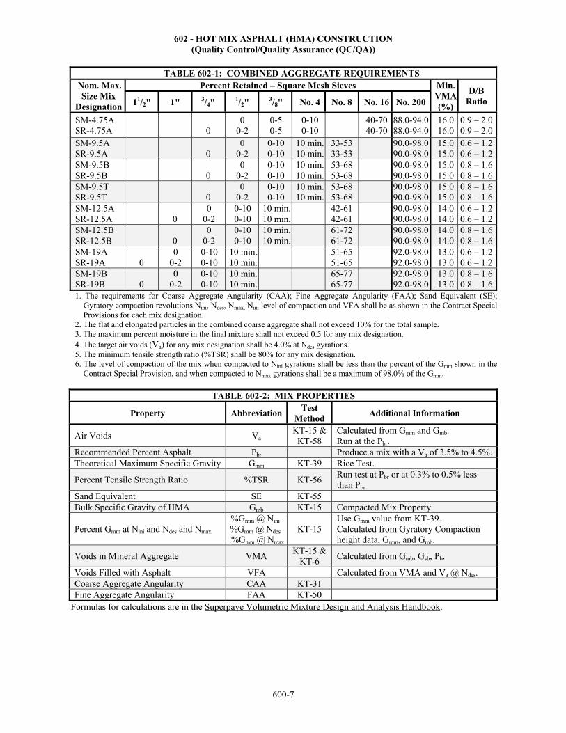
602 - HOT MIX ASPHALT (HMA) CONSTRUCTION (Quality Control/Quality Assurance (QC/QA))
600-7
TABLE 602-1: COMBINED AGGREGATE REQUIREMENTS Nom. Max. Size Mix
Designation
Percent Retained – Square Mesh Sieves Min. VMA (%)
D/B Ratio 11/2" 1" 3/4" 1/2" 3/8" No. 4 No. 8 No. 16 No. 200
SM-4.75A SR-4.75A
0
0 0-2
0-5 0-5
0-10 0-10
40-7040-70
88.0-94.0 88.0-94.0
16.0 16.0
0.9 – 2.00.9 – 2.0
SM-9.5A SR-9.5A
0
0 0-2
0-10 0-10
10 min.10 min.
33-53 33-53
90.0-98.0 90.0-98.0
15.0 15.0
0.6 – 1.20.6 – 1.2
SM-9.5B SR-9.5B
0
0 0-2
0-10 0-10
10 min.10 min.
53-68 53-68
90.0-98.0 90.0-98.0
15.0 15.0
0.8 – 1.60.8 – 1.6
SM-9.5T SR-9.5T
0
0 0-2
0-10 0-10
10 min.10 min.
53-68 53-68
90.0-98.0 90.0-98.0
15.0 15.0
0.8 – 1.60.8 – 1.6
SM-12.5A SR-12.5A
0
0 0-2
0-10 0-10
10 min.10 min.
42-61 42-61
90.0-98.0 90.0-98.0
14.0 14.0
0.6 – 1.20.6 – 1.2
SM-12.5B SR-12.5B
0
0 0-2
0-10 0-10
10 min.10 min.
61-72 61-72
90.0-98.0 90.0-98.0
14.0 14.0
0.8 – 1.60.8 – 1.6
SM-19A SR-19A
0
0 0-2
0-10 0-10
10 min.10 min.
51-65 51-65
92.0-98.0 92.0-98.0
13.0 13.0
0.6 – 1.20.6 – 1.2
SM-19B SR-19B
0
0 0-2
0-10 0-10
10 min.10 min.
65-77 65-77
92.0-98.0 92.0-98.0
13.0 13.0
0.8 – 1.60.8 – 1.6
1. The requirements for Coarse Aggregate Angularity (CAA); Fine Aggregate Angularity (FAA); Sand Equivalent (SE); Gyratory compaction revolutions Nini, Ndes, Nmax, Nini level of compaction and VFA shall be as shown in the Contract Special Provisions for each mix designation.
2. The flat and elongated particles in the combined coarse aggregate shall not exceed 10% for the total sample. 3. The maximum percent moisture in the final mixture shall not exceed 0.5 for any mix designation. 4. The target air voids (Va) for any mix designation shall be 4.0% at Ndes gyrations. 5. The minimum tensile strength ratio (%TSR) shall be 80% for any mix designation. 6. The level of compaction of the mix when compacted to Nini gyrations shall be less than the percent of the Gmm shown in the
Contract Special Provision, and when compacted to Nmax gyrations shall be a maximum of 98.0% of the Gmm.
TABLE 602-2: MIX PROPERTIES
Property AbbreviationTest
Method Additional Information
Air Voids Va KT-15 &
KT-58 Calculated from Gmm and Gmb. Run at the Pbr.
Recommended Percent Asphalt Pbr Produce a mix with a Va of 3.5% to 4.5%.Theoretical Maximum Specific Gravity Gmm KT-39 Rice Test.
Percent Tensile Strength Ratio %TSR KT-56 Run test at Pbr or at 0.3% to 0.5% less than Pbr
Sand Equivalent SE KT-55 Bulk Specific Gravity of HMA Gmb KT-15 Compacted Mix Property.
Percent Gmm at Nini and Ndes and Nmax %Gmm @ Nini
%Gmm @ Ndes
%Gmm @ Nmax
KT-15 Use Gmm value from KT-39. Calculated from Gyratory Compaction height data, Gmm, and Gmb.
Voids in Mineral Aggregate VMA KT-15 &
KT-6 Calculated from Gmb, Gsb, Pb.
Voids Filled with Asphalt VFA Calculated from VMA and Va @ Ndes. Coarse Aggregate Angularity CAA KT-31 Fine Aggregate Angularity FAA KT-50
Formulas for calculations are in the Superpave Volumetric Mixture Design and Analysis Handbook.

602 - HOT MIX ASPHALT (HMA) CONSTRUCTION (Quality Control/Quality Assurance (QC/QA))
600-8
TABLE 602-3: MATERIAL SUBMITTALS Submittal Quantity Description Additional Information
Aggregate for KT-15 3 Samples Sized for 6 inch Plugs Comply with Job Mix Gradation. Aggregate for KT-39 2 Samples Sized for Gmm Testing Comply with Job Mix Gradation. Binder for KT-15 As Needed Sized for 3 Plugs at Pbr Binder for KT-39 As Needed Sized for 2 Gmm Tests Each Aggregate for KT-6 As Needed Specific Gravity Test
Uncompacted HMA Sample 35 lbs Cool sample to room temperature
If transported hot and compacted within 2 hours, then requirement to cool sample may be waived by the DME.
Gyratory Plugs at Nmax 2 Plugs Compacted at Pbr Compacted to Nmax.
TABLE 602-4: TEST DATA SUBMITTALS Submittal Information
Asphalt Binder Source, Grade, Specific Gravity, Mixing and Compaction Temperature from the Producer of the asphalt binder.
Each Aggregate Source and Producer, including Legal Description.
Gradation of Each Aggregate
Percentage Retained to nearest 1% (except nearest 0.1% for No. 200 sieve) Derive RAP gradation after residual binder is removed. Derive RAS gradation after residual binder is removed or from the Shingle Aggregate Gradation table in SECTION 1103.
Material Proportioning Proportion of each material is shown in percentage of aggregate. Composite Gradation Based on Gradation of Each Aggregate and Material Proportioning. Composite Gradation Plot Plotted on KDOT Form 712 (0.45 power graph paper). Asphalt Binder Added Percentage to nearest 0.01% based on total weight of the mixture. Aggregate Percentage of flat and elongated particles in the coarse aggregate, CAA and FAA. %TSR Percent Tensile Strength Ratio of the Mixture (Modified Lottman Test). Sand Equivalent SE for the combined virgin aggregates.
TABLE 602-5: RAP AND RAS TEST DATA SUBMITTALS Submittal Information
RAP and RAS Source and location where RAP will be obtained. Source and location where RAS will be obtained.
RAP Aggregate
Bulk Specific Gravity (Gsb). Use the Gsb provided on the Contract Special Provision. If no value is provided, the Effective Specific Gravity (Gse) shall be calculated as shown in subsection 5.10.4, Part V and used as the Gsb.
RAS Aggregate Bulk Specific Gravity (Gsb). The Effective Specific Gravity (Gse) shall be calculated as shown in subsection 5.10.4, Part V and used as the Gsb.
Asphalt Binder Content of RAP Asphalt Binder Content of RAS
Determined from ignition oven analysis using KT-57.
RAP Gmm
RAS Gmm Determined by KT-39.
Asphalt Binder Specific Gravity
Specific Gravity of the asphalt binder in the RAP and RAS (Gb) shall be set equal to 1.035.
Corrected Asphalt Binder Content of the total recycled mixture
Determined from ignition oven analysis using KT-57.
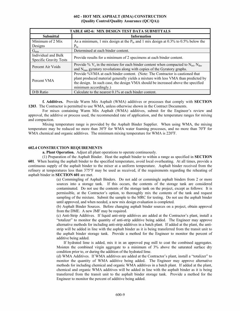
602 - HOT MIX ASPHALT (HMA) CONSTRUCTION (Quality Control/Quality Assurance (QC/QA))
600-9
TABLE 602-6: MIX DESIGN TEST DATA SUBMITTALS Submittal Information
Minimum of 2 Mix Designs
As a minimum, 1 mix design at the Pbr and 1 mix design at 0.3% to 0.5% below the Pbr
Gmm Determined at each binder content. Individual and Bulk Specific Gravity Tests
Provide results for a minimum of 2 specimens at each binder content.
Percent Air Voids Provide % Va in the mixture for each binder content when compacted to Nini, Ndes and Nmax gyratory revolutions along with copies of the Gyratory graphs.
Percent VMA
Provide %VMA at each binder content. (Note: The Contractor is cautioned that plant produced material generally yields a mixture with less VMA than predicted by the design. In such case, the design VMA should be increased above the specified minimum accordingly.)
D/B Ratio Calculate to the nearest 0.1% at each binder content.
f. Additives. Provide Warm Mix Asphalt (WMA) additives or processes that comply with SECTION 1203. The Contractor is permitted to use WMA, unless otherwise shown in the Contract Documents.
For mixes containing Warm Mix Asphalt (WMA) additives, submit for the Engineer’s review and approval, the additive or process used, the recommended rate of application, and the temperature ranges for mixing and compaction.
Mixing temperature range is provided by the Asphalt Binder Supplier. When using WMA, the mixing temperature may be reduced no more than 30oF for WMA water foaming processes, and no more than 70oF for WMA chemical and organic additives. The minimum mixing temperature for WMA is 220oF.
602.4 CONSTRUCTION REQUIREMENTS a. Plant Operation. Adjust all plant operations to operate continuously. (1) Preparation of the Asphalt Binder. Heat the asphalt binder to within a range as specified in SECTION 601. When heating the asphalt binder to the specified temperature, avoid local overheating. At all times, provide a continuous supply of the asphalt binder to the mixer at a uniform temperature. Asphalt binder received from the refinery at temperatures less than 375°F may be used as received, if the requirements regarding the reheating of asphalt binder in SECTION 601 are met.
(a) Commingling of Asphalt Binders. Do not add or commingle asphalt binders from 2 or more sources into a storage tank. If this occurs, the contents of the storage tank are considered contaminated. Do not use the contents of the storage tank on the project, except as follows: It is permissible, at the Contractor’s option, to thoroughly mix the contents of the tank and request sampling of the mixture. Submit the sample to the MRC for testing. Do not use the asphalt binder until approved, and when needed, a new mix design evaluation is completed. (b) Asphalt Binder Sources. Before changing asphalt binder sources on a project, obtain approval from the DME. A new JMF may be required. (c) Anti-Strip Additives. If liquid anti-strip additives are added at the Contractor’s plant, install a “totalizer” to monitor the quantity of anti-strip additive being added. The Engineer may approve alternative methods for including anti-strip additives in a batch plant. If added at the plant, the anti-strip will be added in line with the asphalt binder as it is being transferred from the transit unit to the asphalt binder storage tank. Provide a method for the Engineer to monitor the percent of additive being added.
If hydrated lime is added, mix it in an approved pug mill to coat the combined aggregates. Moisten the combined virgin aggregate to a minimum of 3% above the saturated surface dry condition prior to, or during the addition of the hydrated lime. (d) WMA Additives. If WMA additives are added at the Contractor’s plant, install a “totalizer” to monitor the quantity of WMA additive being added. The Engineer may approve alternative methods for including chemical and organic WMA additives in a batch plant. If added at the plant, chemical and organic WMA additives will be added in line with the asphalt binder as it is being transferred from the transit unit to the asphalt binder storage tank. Provide a method for the Engineer to monitor the percent of additive being added.

602 - HOT MIX ASPHALT (HMA) CONSTRUCTION (Quality Control/Quality Assurance (QC/QA))
600-10
(2) Preparation of Mineral Aggregate. When the mineral aggregate is composed of 2 or more ingredients, combine as shown in the approved JMF.
(a) Temperature Requirements. Dry the aggregate for the mixture and heat to a temperature to obtain an asphalt-aggregate mixture temperature immediately after mixing within the 75 to 150 second Saybolt viscosity range of the asphalt binder used. Obtain the temperature for this viscosity range from the MRC or the Asphalt Binder Producer. No mixing or compaction temperatures are to exceed 340ºF without approval from the Field Materials Engineer. The minimum temperature may be revised by the DME provided it is demonstrated that satisfactory results may be obtained at a lower temperature. In such event, deliver the HMA to the paver at a temperature sufficient to allow the material to be satisfactorily placed and compacted to the specified density and surface tolerance requirements.
(3) Preparation of HMA. Introduce asphalt binder into the prepared aggregate in the proportionate amount determined by the Pbr in the JMF.
(a) Basis of Rejection. HMA will be rejected if the aggregate, as it is discharged from the drum or the pugmill, contains sufficient moisture to cause foaming of the mixture, or if the temperature of the aggregate is such that the asphalt-aggregate mixture temperature is outside the range specified in SECTION 601. (b) Mixing Time. Operate drum mixers at a rate to provide uniform aggregate coating in a continuous operation. For batch and continuous type plants, the minimum wet mixing time is 40 seconds. In all cases, mix a sufficient time to produce a uniform mixture in which all the aggregate particles are thoroughly coated. On batch plants, begin the timing at the start of the asphalt binder introduction into the pugmill, and end upon the opening of the discharge gate. For continuous flow plants, mixing time in seconds shall equal:
[pugmill dead capacity in pounds] divided by [pugmill output in pounds per second]. (c) Manufacturer’s Specifications. Operate all drying, pumping and mixing equipment within the limits specified by the manufacturer, unless it can be demonstrated to the satisfaction of the Engineer that such limits may be exceeded without detriment to the HMA. (d) Batcher Operation. Coordinate HMA batchers (Gob Hoppers) with the plant production rate at all times so the hopper is more than ¾ full before the gates open, and the gates close before material can drop through the gob hopper directly into the surge bin, weigh hopper or truck. (e) Wasted Material. Wasted material is not measured for pay.
If after an interruption of production, the drum-mixer contains cold, uncoated or otherwise unsuitable material, waste material through a diversion chute. In a continuous or batch plant drier, waste unsuitable material through the pugmill.
At the end of a production run, waste any segregated material in the cone of the storage bin. (4) End of Day Quantities. At the end of each day of production provide the Engineer with a document
signed by the Plant Foreman or the Project Manager listing the dry weight of each aggregate, mineral filler, RAP, and WMA chemical or organic additive; the tons of asphalt binder, the tons of anti-strip agent used for the project during the day, and the tons of water used in the WMA foaming process. The dry weight is the tons of the material less the water content.
b. Road Surface Preparation. (1) Preparation of Earth Subgrade. When the HMA is placed on a prepared subgrade, and unless other subgrade preparation is called for in the Contract Documents, perform the following:
At all grade control points, such as existing pavements and bridges, excavate the subgrade according to the specified grades and lines, prior to any subgrade treatment. Prior to the delivery of materials for the base course, prepare the subgrade surface by sprinkling with water, lightly scarifying where necessary, and blading and rolling, until the proper crown is obtained. Disturb the originally compacted crust or top portion of the subgrade as little as possible. Maintain the subgrade as prepared until it is covered with the base course. Repair any defects which may develop, at the Contractor’s expense, to the satisfaction of the Engineer. (2) Trimming of Subgrade (Untreated, Treated or Modified), Aggregate Base or Granular Sub-base for HMA Pavement. Before placing the subsequent layer of the pavement structure, trim the subgrade (untreated, treated or modified), aggregate base or granular subbase. Use an automated, electronically controlled machine that trims with a rotary cross-shaft trimmer to establish and control the line, grade and typical cross-section as shown in the Contract Documents. The Engineer may waive the use of automatically controlled equipment on areas of narrow width or
602 - HOT MIX ASPHALT (HMA) CONSTRUCTION (Quality Control/Quality Assurance (QC/QA))
600-11
irregular dimensions. Operate all trimming equipment far enough in advance of the paving operation to allow ample opportunity to check the grade and make any needed corrections. Prior to paving, construct ditches and drains to drain the highway effectively. Maintain the finished subgrade in a smooth and compacted condition to readily drain.
Do not place pavement upon a frozen or muddy subgrade. (3) Preparation of an Existing Asphalt Pavement. Clean the surface to remove all foreign material and broom to remove dust. Excavate areas shown in the Contract Documents to be patched to a depth directed by the Engineer. Fill with HMA and compact. (4) Preparation of an Existing Concrete or Brick Pavement. Clean all foreign material and broom to remove dust. Clean and fill cracks and joints, and construct surface leveling as shown in the Contract Documents. (5) Tack Coat. Prior to placing the HMA, apply a tack coat to the existing surface, as shown in the Contract Documents. When warranted by weather conditions, the Engineer may authorize a change in the asphalt for tack coat. When such changes are made, the price per ton of material being used will be the unit price bid for the material designated in the contract plus or minus the difference in the invoice price per ton of the 2 materials at the refinery as determined at the time of application. c. Weighing Operations. See SECTION 109 for details regarding weighing operations. d. Hauling Operations. Schedule operations to minimize hauling over a surface course. Deliver HMA to the paver at a temperature sufficient to allow the material to be placed and compacted to the specified density and surface tolerance. e. Paving Operations. Except when placing SM-4.75A, SM-9.5A or SR-9.5A asphalt mixtures, remix the material transferred from the hauling unit, prior to placement. Use equipment such as a mobile conveyor, material transfer device, shuttle buggy material transfer vehicle, material transfer paver or paver with remixer conveyor system. After starting the project with the equipment listed above, and after producing HMA pavement density within the limits specified in TABLE 602-7, the Engineer will consider other types of equipment or modifications to pavers that will produce less segregation. The use of equipment as noted above shall not relieve the Contractor of the responsibility to comply with TABLE 602-7. The Engineer will check the pavement for longitudinal streaks and other irregularities. Make every effort to prevent or correct any irregularities in the pavement, such as changing pavers or using different and additional equipment. Do not raise (dump) the wings of the paver receiving hopper at any time during the paving operation. The Engineer may waive this requirement if it is determined that raising (dumping) the wings will not produce detrimental segregation. If segregation or irregularities in the pavement surface or density are noted, review the plant, hauling and paving operations and take corrective action. The recommendations made in KDOT’s "Segregation Check Points" should reduce the segregation and irregularities to an acceptable level. Copies of KDOT’s "Segregation Check Points" may be obtained from the KDOT District Office or Field Engineer. Spread the HMA and finish to the specified crown and grade using an automatically controlled HMA paver. Operate the paver at a speed to provide a uniform rate of placement without undue interruption. At all times, keep the paver hopper sufficiently full to prevent non-uniform flow of the HMA to the augers and screed. If the automatic grade control devices break down, the Engineer may allow the paver to operate to the close of the working day, provided the surface is satisfactory. Do not operate the paver without working automatic control devices upon another lift that was laid without automatic controls. (1) Surface Quality. Spread the HMA without tearing the surface. Strike a finish that is smooth, free of segregation, true to cross section, uniform in density and texture and free from surface irregularities. If the pavement does not comply with all of these requirements, plant production and paving will be suspended until the deficiency is corrected. The Engineer will check segregation and uniformity of density using methods outlined in Section 5.8.3 - Segregation Check Using the Nuclear Density Gauge, Part V. For shoulders with a plan width of less than or equal to 3 feet, and placed at the same time as the traveled way, do not take nuclear density readings on the shoulder nor within 1 foot of the shoulder unless the pavement section is uniform across the entire roadway. The acceptable criteria for density uniformity are in TABLE 602-7.

602 - HOT MIX ASPHALT (HMA) CONSTRUCTION (Quality Control/Quality Assurance (QC/QA))
600-12
TABLE 602-7: SEGREGATION AND UNIFORMITY OF DENSITY CHECK
Mix Designation Maximum Density Range
(highest minus lowest) Maximum Density Drop (average minus lowest)
All 4.4 lbs./cu. ft. 2.2 lbs./cu. ft. Whenever the results from 2 consecutive density profiles fail to comply with both of the requirements listed in
TABLE 602-7, plant production and paving will be suspended. Follow the procedures listed in the Profile Evaluation Subsection of Section 5.8.3-Segregation Check Using the Nuclear Density Gauge, Part V until production may be resumed.
Joint density testing and the associated requirements listed below do not apply for HMA lift thicknesses less than or equal to 1 inch. Evaluate the longitudinal joint density using methods outlined in Section 5.8.4-Joint Density Evaluation Using the Nuclear Density Gauge, Part V. Although it is the Contractor’s responsibility to perform the joint density evaluation, the Engineer may make as many independent joint density verifications as deemed necessary at the random sample locations. The Engineer’s results will be used for acceptance for joint density, whenever available. The acceptable criteria for joint density are in TABLE 602-8.
TABLE 602-8: JOINT DENSITY REQUIREMENTS Nuclear Gauge Readings Requirement
Interior Density minus Joint Density ≤ 3.0 lbs./cu. ft. OR
Joint Density ≥ 90.00% of Gmm
If the results of 2 consecutive density profiles fail to comply with TABLE 602-8, the plant production and paving operations will be suspended. Follow the procedures listed in the Joint Evaluation Subsection of Section 5.8.4-Joint Density Evaluation Using the Nuclear Density Gauge, Part V, until production may be resumed.
(2) Leveling Courses. In general, spread leveling course mixtures by the method to produce the best results under prevailing conditions to secure a smooth base of uniform grade and cross section. The leveling course may be spread with a properly equipped paver or motor grader.
(3) Lift Thickness. Except for leveling courses or when shown otherwise in the Contract Documents, TABLE 602-9 applies. The Engineer may adjust lift thickness to utilize the most efficient method of acquiring specified density and surface quality. The minimum lift thickness for any HMA mixture is 3 times the nominal maximum aggregate size, unless otherwise designated in the Contract Documents or approved by the Engineer.
TABLE 602-9: NOMINAL COMPACTED THICKNESS
Lift Maximum Nominal Compacted Thickness Surface 2 inches Base 4 inches
(4) Grade Control. Achieve grade control by use of 1 or more of the following grade reference devices. Approval of any of these devices will be based upon satisfactory performance.
(a) Traveling Stringline. Attach a traveling stringline or ski type attachment, a minimum length of 30 feet, to the paver and operate parallel with its line of travel. (b) Reference Shoe. Attach a short reference shoe or joint matching device to the paver for control in matching surface grades along longitudinal joints. (c) Erect Stringline. Use an erected stringline consisting of a tightly stretched wire or string offset from and parallel to the pavement edge on 1 or both sides. Erect the stringline parallel to the established pavement surface grade and support at intervals as necessary to maintain the established grade and alignment. (d) Stringless Paving. Control line, grade and pavement cross-section as shown in the Contract Documents. Use electronic guidance systems that meet the requirements and tolerances listed in SECTION 802. Horizontal control is guided by GPS. Vertical control is guided by Total Stations. GPS will not be allowed for Vertical control.
602 - HOT MIX ASPHALT (HMA) CONSTRUCTION (Quality Control/Quality Assurance (QC/QA))
600-13
When paving on a fresh subgrade that has not been trimmed by an automatically controlled machine, use an erected stringline or stringless paving to establish grade. Use either of these options on the first or second lift. When directed by the Engineer, use an erected stringline or stringless paving to match grade control points such as bridges.
(5) Compaction of Mixtures. Uniformly compact the HMA as soon after spreading and strike-off as possible without shoving or tearing. Use self-propelled rollers operated at speeds slow enough to avoid displacement of the HMA. Equipment and rolling procedures which result in excessive crushing of the aggregate are prohibited. Use a sufficient number and weight of rollers to compact the HMA to the required density, using a minimum of 2 rollers. See subsections 602.4e.(6) for exceptions to the minimum number of rollers. Perform final rolling with a steel roller unless otherwise specified. On the final pass, operate finishing, vibratory rollers in the static mode. Coordinate the frequency, amplitude and forward speed of the vibratory roller to achieve satisfactory compaction without objectionable undulations. For HMA lifts with a compacted thickness less than 1¼ inch, operate vibratory rollers in the static mode. Keep rollers in operation as necessary so all parts of the pavement receive substantially equal compaction at the proper time. The Engineer will suspend HMA delivery to the project at any time proper compaction is not being performed. Remove, replace with suitable material and finish according to these specifications any mixture that becomes loose, broken, mixed with foreign material or which does not comply in all respects with the specifications.
(6) Density Requirements. (a) For mixes with a specified thickness greater than or equal to 1 ½ inches: For lots 1 and 2, control density as shown in subsection 602.4e.(6)(b). Before beginning production, the Contractor has the option to accept the pay adjustment for density on both Lots 1 and 2, or only Lot 2. If the Contractor chooses to accept the pay adjustments for density on both Lots 1 and 2, or only Lot 2, control the density as shown in subsections 602.4e.(6)(a)(i-ii). If the Contractor chooses to accept pay adjustment for density on Lot 1, the pay adjustment can not be rejected on Lot 2. (i) HMA Overlay. For lots 3 and greater, the lot density requirements and appropriate density pay adjustment factors are shown in subsection 602.9b. as the percent of the Gmm value based on the average of the density tests. The standard lot size is 10 density tests. Smaller lot sizes may result as outlined in TABLE 602-10. Normally, the Gmm value used to calculate the density percentage is the average value of all Gmm tests conducted the same day the lot was placed and compacted. If less than 3 Gmm values were obtained that day, use the moving average value (last 4 tests prior to the end of the day). When starting a mix and less than 4 Gmm values have been determined, use the average value of those available at the end of each day. (ii) HMA Surface, HMA Base and HMA Pavement. For lots 3 and greater, the lower specification limit (LSL) value for density is given in subsection 602.9c. along with the appropriate density pay adjustment factor equations. The LSL value is given as a percentage of Gmm. Lot density is determined using the measured density values for all sublots in a lot. The standard lot size is 10 density tests. Smaller lot sizes may result as outlined in TABLE 602-10. Normally, the Gmm value used to calculate the density percentage is the average value of all Gmm tests conducted the same day the lot was placed and compacted. If less than 3 Gmm values were obtained that day, use the moving average value (last 4 tests prior to the end of the day). When starting a mix and less than 4 Gmm values have been determined, use the average value of those available at the end of each day. (b) For mixes with a specified thickness less than 1½ inches:
These mixes will not have a density pay adjustment. Control density using an approved rolling procedure with random nuclear gauge density determinations. Include a method for controlling density in the QCP.
Designate a "Compaction Foreman". This person shall control compaction procedures, review nuclear gauge results as they are obtained, adjust compaction procedures as needed to optimize compaction and report any changes in the compaction process and results of nuclear gauge testing to the Engineer. The compaction foreman may also be the nuclear gauge operator. The nuclear gauge operator shall continuously monitor compaction procedures. As a minimum, take 10 random nuclear gauge density determinations per day and report results to the Engineer. Throughout the day, nuclear gauge results shall be available for review by the Engineer. The
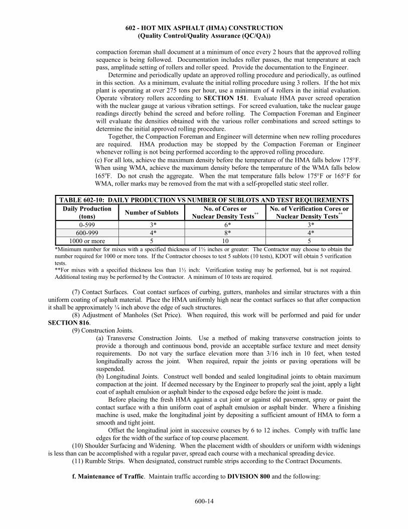
602 - HOT MIX ASPHALT (HMA) CONSTRUCTION (Quality Control/Quality Assurance (QC/QA))
600-14
compaction foreman shall document at a minimum of once every 2 hours that the approved rolling sequence is being followed. Documentation includes roller passes, the mat temperature at each pass, amplitude setting of rollers and roller speed. Provide the documentation to the Engineer.
Determine and periodically update an approved rolling procedure and periodically, as outlined in this section. As a minimum, evaluate the initial rolling procedure using 3 rollers. If the hot mix plant is operating at over 275 tons per hour, use a minimum of 4 rollers in the initial evaluation. Operate vibratory rollers according to SECTION 151. Evaluate HMA paver screed operation with the nuclear gauge at various vibration settings. For screed evaluation, take the nuclear gauge readings directly behind the screed and before rolling. The Compaction Foreman and Engineer will evaluate the densities obtained with the various roller combinations and screed settings to determine the initial approved rolling procedure.
Together, the Compaction Foreman and Engineer will determine when new rolling procedures are required. HMA production may be stopped by the Compaction Foreman or Engineer whenever rolling is not being performed according to the approved rolling procedure. (c) For all lots, achieve the maximum density before the temperature of the HMA falls below 175F. When using WMA, achieve the maximum density before the temperature of the WMA falls below 165oF. Do not crush the aggregate. When the mat temperature falls below 175F or 165F for WMA, roller marks may be removed from the mat with a self-propelled static steel roller.
TABLE 602-10: DAILY PRODUCTION VS NUMBER OF SUBLOTS AND TEST REQUIREMENTSDaily Production
(tons) Number of Sublots
No. of Cores or Nuclear Density Tests**
No. of Verification Cores or Nuclear Density Tests**
0-599 3* 6* 3* 600-999 4* 8* 4*
1000 or more 5 10 5 *Minimum number for mixes with a specified thickness of 1½ inches or greater: The Contractor may choose to obtain the number required for 1000 or more tons. If the Contractor chooses to test 5 sublots (10 tests), KDOT will obtain 5 verification tests. **For mixes with a specified thickness less than 1½ inch: Verification testing may be performed, but is not required. Additional testing may be performed by the Contractor. A minimum of 10 tests are required.
(7) Contact Surfaces. Coat contact surfaces of curbing, gutters, manholes and similar structures with a thin
uniform coating of asphalt material. Place the HMA uniformly high near the contact surfaces so that after compaction it shall be approximately ¼ inch above the edge of such structures. (8) Adjustment of Manholes (Set Price). When required, this work will be performed and paid for under SECTION 816. (9) Construction Joints.
(a) Transverse Construction Joints. Use a method of making transverse construction joints to provide a thorough and continuous bond, provide an acceptable surface texture and meet density requirements. Do not vary the surface elevation more than 3/16 inch in 10 feet, when tested longitudinally across the joint. When required, repair the joints or paving operations will be suspended. (b) Longitudinal Joints. Construct well bonded and sealed longitudinal joints to obtain maximum compaction at the joint. If deemed necessary by the Engineer to properly seal the joint, apply a light coat of asphalt emulsion or asphalt binder to the exposed edge before the joint is made.
Before placing the fresh HMA against a cut joint or against old pavement, spray or paint the contact surface with a thin uniform coat of asphalt emulsion or asphalt binder. Where a finishing machine is used, make the longitudinal joint by depositing a sufficient amount of HMA to form a smooth and tight joint.
Offset the longitudinal joint in successive courses by 6 to 12 inches. Comply with traffic lane edges for the width of the surface of top course placement.
(10) Shoulder Surfacing and Widening. When the placement width of shoulders or uniform width widenings is less than can be accomplished with a regular paver, spread each course with a mechanical spreading device. (11) Rumble Strips. When designated, construct rumble strips according to the Contract Documents. f. Maintenance of Traffic. Maintain traffic according to DIVISION 800 and the following:

602 - HOT MIX ASPHALT (HMA) CONSTRUCTION (Quality Control/Quality Assurance (QC/QA))
600-15
Maintain one-way traffic, and restrict traffic speeds to 20 miles per hour in the vicinity of workers, unless otherwise designated. Use pilot cars to lead traffic through the area of paving and rolling operations, and if directed, through a curing area. The use of flaggers is allowed through patching operations, unless the patching area or distance between flaggers exceeds ½ mile, in which case the use of a pilot car shall be required. On overlay projects with 2 lanes or more in each direction for traffic use, the Engineer may waive the pilot car requirements. Station one flagger ahead of the application of the tack coat and one flagger ahead of the area being protected from traffic. Take adequate protection for traffic on side roads approaching the tack area. g. Treatment of Adjacent Areas. Pave sideroads, entrances and turnouts for mailboxes as shown in the Contract Documents. Overlay all widening areas designated in the Contract Documents or ordered by the Engineer.
h. Pavement Smoothness. Evaluate pavement smoothness according to SECTION 603 and the following:
TABLE 602-11: MAXIMUM VARIATION OF THE SURFACE
Length (feet) Maximum Variation of the Surface
(inches) 10 3/16 25 5/16
Correct all humps or depressions exceeding the specified tolerance by removing the defective work and
overlaying with new material, or by other means approved by the Engineer. All necessary corrections are at the Contractor’s expense. 602.5 PROCESS CONTROL a. General. Establish gradation limits and proportions for each individual aggregate, mineral filler and RAP and RAS, when applicable. Specify the limits and proportions such that the material produced complies with the applicable requirements of the designated mix type. The Contractor is responsible for all process control operations including testing. At no time will KDOT’s representative issue instructions to the Contractor or producer as to setting of dials, gauges, scales and meters. KDOT will collect and test verification samples and assurance samples and inspect the Contractor’s quality control operations.
b. JMF Adjustments. Produce a mixture of uniform composition closely complying with approved design JMF to obtain the specified properties when compacted. If, during production, results from quality control tests demonstrate a need to make adjustments to the mix design, then make adjustments to the design JMF single point gradation and binder content to achieve the specified properties. The JMF adjustments shall produce a mix that complies with TABLE 602-1 for the specified mix designation. When necessary, adjust on a sublot basis. Report the new JMF to KDOT’s field representative and the DME before making such changes, and submit a new mix design for review and approval if required by the DME.
c. Specification Working Ranges. Establish acceptable limits for field test results by applying the tolerances shown in TABLE 602-12 to the JMF or adjusted JMF for binder content. Establish acceptable limits for the other listed mix characteristics by applying the tolerances shown in TABLE 602-12 to the requirements of TABLE 602-1.

602 - HOT MIX ASPHALT (HMA) CONSTRUCTION (Quality Control/Quality Assurance (QC/QA))
600-16
TABLE 602-12: SPECIFICATION WORKING RANGES (QC/QA)
Mix Characteristic Tolerance from JMF
Single Test Value Plot 4 Point Moving Average Value
Plot
Binder Content ±0.6% * ±0.3% *
Mix Characteristic Tolerance for Specification Limits
Single Test Value Plot 4 Point Moving Average Value
Plot
Gradation (applicable sieves in TABLE 602-1) N/A * zero tolerance * Air Voids @ Ndes gyrations ±2.0% * N/A Voids in Mineral Aggregate (VMA) 1.0% below min. * zero tolerance * Voids Filled with Asphalt (VFA) N/A zero tolerance * Course Aggregate Angularity (CAA) zero tolerance N/A Sand Equivalent (SE) zero tolerance N/A Fine Aggregate Uncompacted Voids (FAA) zero tolerance N/A %Tensile Strength Ratio (%TSR) zero tolerance * N/A Density @ Nini and Nmax N/A zero tolerance Dust to Effective Binder (D/B) Ratio zero tolerance * zero tolerance *
* Plot data according to subsection 106.4. For gradations, as a minimum, plot the No. 4, 8, 30 and 200 sieves. Plot Gmm to third decimal point.
Indicate Job Mix Formula (JMF) and specification working range limits for single test results on the control charts using a green ink dotted line.
Indicate the specification working range limits for the 4-point moving average results with a green ink solid line.
d. Mixes with Reclaimed Asphalt Pavement (RAP). The intent of this section is to prevent more RAP going into a mix than is allowed in the Contract Documents. Totalizers are used to determine the %RAP in mix; however, this does not preclude the Engineer from using other methods for determining the %RAP in a mix. Provide the Engineer with the totalizer readings at the end of each day of production. These shall include the final daily readings for the RAP, virgin aggregates and asphalt binder. The %RAP will be checked a minimum of twice a day by the Engineer. Take the readings a minimum of 2 hours apart and a maximum of 6 hours apart. Do not take the readings within the first hour of start-up as adjustments to the plant are most frequent within this time frame. Calculate RAP percentages using the plant totalizers for the virgin aggregates (AGGv), and the RAP as follows:
Equation A: AGGvRAP
100*RAP%RAP
%RAP is the percent RAP in the total aggregates (Virgin and RAP) rounded to the nearest tenth. RAP is the difference between the current and last reading of the RAP totalizer in tons. AGGv is the difference between the current and last reading of the Virgin Aggregate totalizer in tons.
%RAP is considered out of compliance when any of the following occurs: Any single test exceeds the maximum percentage allowed by specs by 3%. The 4-point moving average exceeds the maximum percentage allowed by specifications.
Actions to be taken if the %RAP is out of compliance: If any single test exceeds 3% of the maximum allowed %RAP stop production, perform the “0 check
run” on the belts in the presence of the Engineer, and make adjustments to correct the discrepancy. If the 4-point moving average exceeds the maximum allowed %RAP three consecutive times, stop
production, perform the “0 check run” on the belts in the presence of the Engineer, and make adjustments to correct the discrepancy.
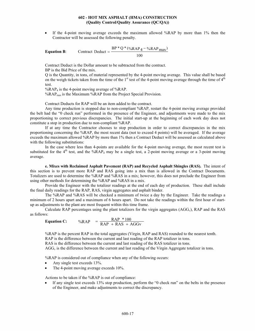
602 - HOT MIX ASPHALT (HMA) CONSTRUCTION (Quality Control/Quality Assurance (QC/QA))
600-17
If the 4-point moving average exceeds the maximum allowed %RAP by more than 1% then theContractor will be assessed the following penalty.
Equation B: Contract 100
)RAP% max%RAP 4(*Q*BPeductD
Contract Deduct is the Dollar amount to be subtracted from the contract. BP is the Bid Price of the mix. Q is the Quantity, in tons, of material represented by the 4-point moving average. This value shall be based on the weigh tickets taken from the time of the 1st test of the 4-point moving average through the time of 4th test. %RAP4 is the 4-point moving average of %RAP. %RAPmax is the Maximum %RAP from the Project Special Provision.
Contract Deducts for RAP will be an item added to the contract. Any time production is stopped due to non-compliant %RAP, restart the 4-point moving average provided
the belt had the “0 check run” performed in the presence of the Engineer, and adjustments were made to the mix proportioning to correct previous discrepancies. The initial start-up at the beginning of each work day does not constitute a stop in production due to non-compliant %RAP.
If at any time the Contractor chooses to stop production in order to correct discrepancies in the mix proportioning concerning the %RAP, the most recent data (not to exceed 4 points) will be averaged. If the average exceeds the maximum allowed %RAP by more than 1% then a Contract Deduct will be assessed as calculated above with the following substitutions:
In the case where less than 4-points are available for the 4-point moving average, the most recent test is substituted for the 4th test, and the %RAP4 may be a single test, a 2-point moving average or a 3-point moving average.
e. Mixes with Reclaimed Asphalt Pavement (RAP) and Recycled Asphalt Shingles (RAS). The intent ofthis section is to prevent more RAP and RAS going into a mix than is allowed in the Contract Documents. Totalizers are used to determine the %RAP and %RAS in a mix; however, this does not preclude the Engineer from using other methods for determining the %RAP and %RAS in a mix.
Provide the Engineer with the totalizer readings at the end of each day of production. These shall include the final daily readings for the RAP, RAS, virgin aggregates and asphalt binder.
The %RAP and %RAS will be checked a minimum of twice a day by the Engineer. Take the readings a minimum of 2 hours apart and a maximum of 6 hours apart. Do not take the readings within the first hour of start-up as adjustments to the plant are most frequent within this time frame.
Calculate RAP percentages using the plant totalizers for the virgin aggregates (AGGv), RAP and the RAS as follows:
Equation C: AGGvRASRAP
100*RAP%RAP
%RAP is the percent RAP in the total aggregates (Virgin, RAP and RAS) rounded to the nearest tenth. RAP is the difference between the current and last reading of the RAP totalizer in tons. RAS is the difference between the current and last reading of the RAS totalizer in tons.
AGGv is the difference between the current and last reading of the Virgin Aggregate totalizer in tons.
%RAP is considered out of compliance when any of the following occurs: Any single test exceeds 13%. The 4-point moving average exceeds 10%.
Actions to be taken if the %RAP is out of compliance: If any single test exceeds 13% stop production, perform the “0 check run” on the belts in the presence
of the Engineer, and make adjustments to correct the discrepancy.

602 - HOT MIX ASPHALT (HMA) CONSTRUCTION (Quality Control/Quality Assurance (QC/QA))
600-18
If the 4-point moving average exceeds 10% three consecutive times, stop production, perform the “0 check run” on the belts in the presence of the Engineer, and make adjustments to correct the discrepancy.
If the 4-point moving average exceeds 11% then the Contractor will be assessed the following penalty.
Equation D: Contract 100
)RAP% max%RAP 4(*Q*BPeductD
Contract Deduct is the Dollar amount to be subtracted from the contract. BP is the Bid Price of the mix. Q is the Quantity, in tons, of material represented by the 4-point moving average. This value shall be based on the weigh tickets taken from the time of the 1st test of the 4-point moving average through the time of 4th test. %RAP4 is the 4-point moving average of %RAP. %RAPmax is 10%.
Calculate RAS percentages using the plant totalizers for the virgin aggregates (AGGv), RAP and the RAS
as follows:
Equation E: AGGvRASRAP
100*RAS%RAS
%RAS is the percent RAS in the total aggregates (Virgin, RAP and RAS) rounded to the nearest tenth. RAP is the difference between the current and last reading of the RAP totalizer in tons.
RAS is the difference between the current and last reading of the RAS totalizer in tons. AGGv is the difference between the current and last reading of the Virgin Aggregate totalizer in tons. %RAS is considered out of compliance when any of the following occurs: Any single test exceeds 6%. The 4-point moving average exceeds 5%.
Actions to be taken if the %RAS is out of compliance: If any single test exceeds 6% stop production, perform the “0 check run” on the belts in the presence of
the Engineer, and make adjustments to correct the discrepancy. If the 4-point moving average exceeds 5% three consecutive times, stop production, perform the “0
check run” on the belts in the presence of the Engineer, and make adjustments to correct the discrepancy.
If the 4-point moving average exceeds 6% then the Contractor will be assessed the following penalty.
Equation F:
100RAS%RAS%*5*Q*BP
DeductContract max4
Contract Deduct is the Dollar amount to be subtracted from the contract. BP is the Bid Price of the mix. Q is the Quantity, in tons, of material represented by the 4-point moving average. This value shall be based on the weigh tickets taken from the time of the 1st test of the 4-point moving average through the time of 4th test. %RAS4 is the 4-point moving average of %RAS. %RASmax is 5%. The deduct for RAP and RAS will each be paid for under a separate Contract Deduct bid item. Any time production is stopped due to non-compliant %RAP or %RAS, restart the 4-point moving average
provided the belt had the “0 check run” performed in the presence of the Engineer, and adjustments were made to the mix proportioning to correct previous discrepancies. The initial start-up at the beginning of each work day does not constitute a stop in production due to non-compliant %RAP or %RAS.

602 - HOT MIX ASPHALT (HMA) CONSTRUCTION (Quality Control/Quality Assurance (QC/QA))
600-19
If at any time the Contractor chooses to stop production in order to correct discrepancies in the mix proportioning concerning the %RAP or %RAS, the most recent data (not to exceed 4 points) will be averaged. If the average exceeds the maximum allowed %RAP or %RAS by more than 1% then a Contract Deduct will be assessed as calculated above with the following substitutions:
In the case where less than 4-points are available for the 4-point moving average, the most recent test is substituted for the 4th test, and the moving average may be a single test, a 2-point moving average or a 3-point moving average. 602.6 COMPACTION TESTING
a. General. Make the density determination of the compacted mixture using test results on random samples selected by the Contractor or Engineer (see subsection 602.2i.(1)) from each lift placed. Select sites according to the approved QCP. Take the nuclear density tests or core samples before placement of the next lift and before opening to construction or public traffic, and no later than the next working day following the date of placement.
Exception to coring after any traffic on the overlay. Do not use this procedure more than twice on any one project or tied projects, unless approved by the Engineer. The Contractor may request re-evaluation by coring. (Testing and coring shall be subsidiary items.) When coring is requested, the follow these procedures for the lot under re-evaluation. (1) Immediately prior to coring, determine nuclear gauge densities in the presence of the Engineer in the locations previously tested. The average nuclear gauge density after traffic will be determined. A Contractor density correction factor will be calculated as follows: the average nuclear gauge density after traffic minus the average nuclear gauge density before traffic. If the calculated Contractor density correction factor is a negative value, the Contractor’s density correction factor will be set equal to zero (normally the density correction factor will be a positive number). (2) Immediately before coring, nuclear gauge densities will be determined by the Engineer in the presence of the Contractor in the locations previously tested. The average nuclear density after traffic will be determined. A KDOT density correction factor will be calculated as follows, the average nuclear gauge density after traffic minus the average nuclear gauge density before traffic. If the calculated KDOT density correction factor is a negative number, KDOT’s density correction factor will be set equal to zero. (3) Determine the Traffic Density Correction Factor. It will be the larger of the Contractor’s density correction factor or KDOT’s density correction factor determined in subsections 602.6a.(1) and (2). (4) With the Engineer present, obtain 1 core from each of the Contractor and KDOT nuclear gauge locations. Mark each core as they are taken. Take the cores to KDOT’s field laboratory for drying and evaluation. Together, the Contractor and Engineer will determine the density of each core. Determine the corrected core density for each Contractor and KDOT core as follows: the core density minus the Traffic Density Correction Factor. (5) Using the corrected Contractor core densities and the corrected KDOT core densities, the Engineer will re-evaluate this lot using the procedures outlined in subsection 602.9. Based on this re-evaluation, the Engineer will inform the Contractor of the lots disposition and density pay adjustment factor. For shoulders with a plan width of less than or equal to 3 feet and placed at the same time as the traveled way, the density pay adjustment factors for the traveled way applies. Acceptance of or pay adjustment for density on all shoulders with a plan width greater than 3 feet and any shoulder not placed at the same time as the traveled way shall be according to subsection 602.9. A lot consists of a day’s production for each lift placed and contains the number of density locations as outlined in TABLE 602-11. Base lot acceptance on 2 test results from each sublot unless the Engineer’s results (1 test per sublot) are used. Va lots and density lots are normally of different sizes. If the lane being placed is to be opened to traffic that day, the Engineer and the Contractor may predetermine the sublot size based on anticipated production. If actual production does not meet anticipated production, the sublot size will be adjusted. The number of tests shall be as outlined in TABLE 602-11. The minimum number of density tests is as listed in TABLE 602-11. The Contractor has the option to take additional tests to provide 10 test results to determine payment. The density pay adjustment factors are computed using formulas in subsection 602.9. The density pay adjustment factors do not apply to sideroads, entrances, crossovers and other incidental surfacing. b. Nuclear Density Tests (For mixes with a specified thickness of 1½ inches or greater.). Take 2 nuclear density tests at random within each sublot. The Engineer will take 1 random nuclear density verification test

602 - HOT MIX ASPHALT (HMA) CONSTRUCTION (Quality Control/Quality Assurance (QC/QA))
600-20
per sublot. Perform nuclear density testing to be used in the determination of the traveled way pay adjustment factors and control of shoulder density. Do not take nuclear gauge readings within 1 foot of a longitudinal joint or edge, nor within 20 feet of a transverse joint. For shoulders with a plan width of less than or equal to 3 feet, and placed at the same time as the traveled way, do not take nuclear density readings on the shoulder nor within 1 foot of the shoulder unless the pavement section is uniform across the entire roadway. Mark the outline of the nuclear gauge on the pavement at each location tested with a method of marking that shall last a minimum of 24 hours. Take the nuclear density test at the random location. Do not move the gauge from this location to maximize or minimize the density results. If the Contractor doubts the accuracy of any of the nuclear density test results, the pavement may be cored at the nuclear gauge test locations. If coring is chosen to determine the density for pay adjustment purposes, then all nuclear density test results representing the lot shall be voided and cores taken as prescribed in subsection 602.6c. Take verification nuclear density tests, 1 per sublot, at random locations selected by the Engineer. Payment factors will be based on the Contractor’s nuclear density test results, provided those results are validated by KDOT’s nuclear density tests.
The Engineer will determine a calibration factor for the Contractor’s nuclear density device at the same time as a calibration factor is determined for KDOT’s device. The Contractor will be afforded the opportunity to observe the calibration procedure whether it is performed at the district laboratory or on the project site. The Engineer should provide calibration factors by the end of the working day following the date of collecting the cores. In cases where this is not possible, the Contractor and the Engineer may agree in advance to accept a zero pay adjustment for the concerned lots.
The Engineer and Contractor will compare nuclear density test results before any traffic is allowed on the roadway. If the Contractor or KDOT density values are suspect, the Engineer may approve re-testing the locations in question. When re-testing is approved, substitute the new nuclear density values for the values in question. Before traffic is allowed on the roadway, the Contractor needs to determine if cores will be taken. c. Cores (For mixes with a specified thickness of 1½ inches or greater.) Take 2 cores at random locations within each sublot. It may be necessary to chill the compacted mixture before coring so that the samples may be removed intact without distortion. Cut the samples using a 4-inch coring device, unless a 6-inch coring device is approved by the Engineer. Mark all samples with the lot number, sublot number and core number.
Transport the cores to the laboratory as soon as possible to prevent damage due to improper handling or exposure to heat. Cut all cores including the Engineer’s verification cores. The Contractor will be paid only for cores cut to calibrate the nuclear gauge, when requested by the Engineer. Use KT-15 Procedure III to determine core density.
Do not take cores within 1 foot of a longitudinal joint or edge, nor within 20 feet of a transverse joint. For shoulders with a plan width of less than or equal to 3 feet, and placed at the same time as the traveled way, do not take cores on the shoulder nor within 1 foot of the shoulder unless the pavement section is uniform across the entire roadway. Take 1 verification core per sublot (at locations selected by the Engineer) for testing at KDOT’s laboratory. Density pay adjustment factors and control of shoulder density are based on the core results, provided those results are validated by the verification cores sent to KDOT’s laboratory. Dry the core holes, tack the sides and bottom, fill with the same type of material and properly compact it by the next working day. 602.7 WEATHER LIMITATIONS Do not place HMA on any wet or frozen surface or when weather conditions otherwise prevent the proper handling and finishing of the mixture. Only place HMA when either the minimum ambient air temperature or the road surface temperature shown in TABLE 602-13 is met.

602 - HOT MIX ASPHALT (HMA) CONSTRUCTION (Quality Control/Quality Assurance (QC/QA))
600-21
TABLE 602-13: MINIMUM HMA PLACEMENT TEMPERATURES
Paving Course Thickness (inches)
Air Temperature (ºF)
Surface Temperature (ºF)
HMA WMA Foam
WMA Chem
HMA WMA Foam
WMA Chem
Surface All 50 45 40 55 50 45 Subsurface <1.5 50 45 40 55 50 45 Subsurface ≥1.5 and < 3 40 35 30 45 40 35 Subsurface ≥ 3 30 30 30 35 32 32
602.8 MIXTURE ACCEPTANCE a. General. Test each mix designation at each plant for compliance with TABLE 602-1. Acceptance will be made on a lot by lot basis contingent upon satisfactory test results. Obtain test samples of the mix designation from the roadway behind the paving operation before compaction. The sampling device and procedures used to obtain the samples must be approved by the Engineer. Use KT-25 for obtaining HMA from the roadway and splitting of the sample. The Contractor’s quality control tests will be used for acceptance provided those results are verified by KDOT.
A load or loads of mixture which, in the opinion of the Engineer, are unacceptable for reasons such as being segregated, aggregate being improperly coated, foaming aggregate or being outside the mixing temperature range may be rejected. Verification samples will be taken by the Engineer at randomly selected locations from behind the paver. Fill all sample locations before compaction. The Va test values will also be used to determine Va pay adjustments according to subsection 602.9d. Va pay adjustments apply to the HMA placed on the traveled way and shoulders (including ramps and acceleration and deceleration lanes). b. Lot Definition for Mix Production Sampling and Testing. A lot is defined as an isolated quantity of a specified material produced from a single source or operation. Each lot shall normally be represented by 4 contiguous test results. A lot may be represented by test results on samples taken from 1 or more day’s production. c. Lot Investigation. The Engineer may examine materials represented by individual test results which lie beyond the Contractor’s normal quality control testing variation. The investigation may be based on either Contractor or KDOT test results. The information from additional testing (including testing of in-place HMA) may be used to define unacceptable work according to SECTION 105. The Engineer may apply appropriate price reductions or initiate corrective action. For any test, if a dispute exists between the Engineer and Contractor about the validity of the other’s test results, the KDOT District Materials Laboratory or the MRC will perform referee testing, except for nuclear density dispute resolution and Va dispute resolution. If the disputed KDOT test results were generated at the District Laboratory, the MRC will perform the referee tests. If the disputed KDOT test result was generated at the MRC, an independent laboratory agreeable to both parties will be selected. The Laboratory shall be accredited by the AASHTO Accreditation Program in the appropriate testing category.
If referee testing indicates that KDOT test results are correct, the Contractor pays for the additional testing, including referee testing performed at the MRC. This will be paid using the bid item Contract Deduct which will be an item added to the contract.
If the referee testing indicates that Contractor test results are correct, KDOT pays for the additional testing. Pay the independent lab for the testing and submit the paid invoice to KDOT. The Engineer will reimburse the Contractor (based on the invoice price) as Extra Work, SECTION 104. (1) For nuclear density dispute resolution (the statistical comparison fails and the Contractor questions KDOT’s results), the following procedure applies:
Discard pay factors previously established with the nuclear gauge, and use the core results to establish the pay factors.
With the Engineer present, take 1 core from each of the locations previously tested with the Contractor’s nuclear gauge and KDOT’s nuclear gauge (normally 15 cores). Mark all cores with the lot number, sublot number and core number.

602 - HOT MIX ASPHALT (HMA) CONSTRUCTION (Quality Control/Quality Assurance (QC/QA))
600-22
Take the cores to the field laboratory and dry to a constant weight before testing. The Contractor and theEngineer, working together, will determine the core densities (KT-15, Procedure III).
A statistical comparison will be made between Contractor and KDOT core results. If the t-test passes,KDOT will pay for all cores. The Contractor’s test results will be used to calculate the density payfactors. If the t-test fails, KDOT will not pay for the cores. KDOT test results will be used to calculatethe density pay factors.
(2) For Va dispute resolution (the statistical comparison fails and the Contractor questions KDOT results), the following procedure applies for the lots in question:
Determine which lots to dispute. Only dispute the lot produced immediately prior to the lot currentlyunder production and being tested. Notify the Engineer, prior to the completion of all Contractor Va
testing for this lot. (When production is completed for any mix, the last lot may be challenged the dayproduction is completed). When the hot mix plant shuts down for the winter, the Contractor has amaximum of 7 calendar days to dispute the last lot produced prior to winter shut down.
Discard Va and Va pay adjustment factors previously determined within the lots being questioned. All saved gyratory compacted Va quality control and verification samples and back half of samples
within the lots in question will be taken by KDOT to the District Materials Laboratory. All back halfof samples shall be a minimum of 35 pounds. Failing to obtain enough material removes the right todispute resolution. Copies of all paperwork, including work sheets, associated with previous Va
calculations for the disputed lots will also be taken to the District Materials Laboratory.
The following retesting will be completed by KDOT: Check the samples to be sure they are dry before retesting. Reweigh the original gyratory compacted
Va quality control and verification samples. Determine the Gmb at Ndes revolutions for all savedgyratory plugs. Compare retest results with original test results. Use this information to isolatepotential testing errors, but continue with the remainder of the retesting steps.
Determine the Gmm using the back half of all samples within each lot being questioned. Normally,there will be 5 back halves (4 Contractor’s and 1 KDOT) to test within each lot.
Compact the back halves to Nmax revolutions and determine the Gmb at Ndes revolutions. Use Gmm determined above and the Gmb determined from the recompacted samples to calculate Va at
Ndes revolutions for the lots in question. Using the retest Va results, a statistical comparison will be made. If the t-test passes, the Contractor’s
retest results will be used to calculate the pay factor and KDOT will pay for all retesting. Use theprocedures shown in subsection 602.9d. If the t-test fails, KDOT’s retest results will be used tocalculate the pay factor, and the Contractor will pay for all retesting.
d. Resampling of Lots. Take no samples for retest for pay adjustment purposes except as noted insubsections 602.6b. and 602.8c.
e. Multiple Projects. If multiple projects are supplied from 1 or more plants using the same mix, carryover the lots at each hot mix plant from project to project.
f. Lot Size. A standard size mix production lot (density test lots are defined in subsection 602.6a.(5))consists of 4 equal sublots of 750 tons each of HMA (lot size is 3,000 tons).
It is anticipated that lot size shall be as specified. However, with the Engineer’s approval, the Contractor may re-define lot size for reasons such as, but not limited to, change in contract quantities or interruption of the work. Take 1 sample during production of each sublot and utilize it to determine disposition of the lot in which it occurs.
g. Increased Lot Size. After 8 consecutive sublots have been produced within the tolerance shown for allmix characteristics listed in TABLE 602-12 and without a Va penalty, the sublot size may be increased to 1,000 tons (lot size of 4,000 tons), provided the normal production rate of the plant is greater than 250 tons per hour. Provide immediate notification of lot size changes to the Engineer any time a change is made.
After 8 additional consecutive sublots have been produced at the 1,000 ton sublot size, the sublot size may again be increased to 1,250 tons per sublot ( lot size of 5,000 tons), provided all 8 consecutive 1,000 ton sublots have been produced within the tolerances shown for all mix characteristics listed in TABLE 602-12, without a Va

602 - HOT MIX ASPHALT (HMA) CONSTRUCTION (Quality Control/Quality Assurance (QC/QA))
600-23
penalty, production rates for the previous 2 days have been greater than 3,750 tons per day, and a minimum of 2 of the last 3 segregation profile checks comply with TABLE 602-14.
TABLE 602-14: SEGREGATION PROFILE CHECKS FOR INCREASED SUBLOT SIZE
Mix Designation Maximum Density Range (highest minus lowest)
Maximum Density Drop (average minus lowest)
All 3.1 lbs./cu. ft. 1.9 lbs./cu. ft.
If subsequent test results fall outside the tolerances shown for any mix characteristic listed in TABLE 602-12 or a Va penalty is incurred, decrease the sublot size to 750 tons. If the production rates fall below 3,750 tons per day for 2 consecutive days or a minimum of 2 of the last 3 segregation profile checks fail the above requirements, then reduce the 1,250 ton sublots size to 1,000 ton per sublot provided the TABLE 602-12 criteria is met and no Va penalty is incurred.
When the increased lot size criteria are again met for 4 consecutive sublots, the sublot may be increased as the limits given above.
h. Decreased Lot Size for Small Quantities. This is to be used when a small quantity (less than 3,000tons) of a particular mix will be used. Use the plan quantity for the lot size. Reduce the sublot size below 750 tons by dividing the lot into 3 or 4 equal sublots. Before beginning production, provide the Engineer with the number and size of the sublots.
i. Pre-Production Mix. Test and evaluate a pre-production mix, limited to a maximum of 200 tons fromeach plant and type of mix before production of that mix. Evaluate the pre-production mix at initial start-up and after suspension of production resulting from failing test results. Do not adjust Va payment for pre-production mixes. Provide a pre-production mix that complies with the gradation, D/B ratio, binder content, VMA, level of compaction for Nini, Ndes, Nmax and laboratory Va requirements prior to starting or resuming production. For binder content, Va at Ndes and VMA, use the "Single Test Value" listed in TABLE 602-12 for comparison. For the other tests listed, use the values listed in TABLE 602-1 for each mix. Except for initial start-up, normal delivery of material to the project before completion of certain test results on pre-production mixes may be authorized by the DME.
Place the material produced for the pre-production mix in locations approved by the DME. On projects where HMA is paid by the ton, consider placing the pre-production mix in non-critical areas such as side roads, entrances, shoulders or deep in the base. The Engineer will pay for material as the material produced, not in the location placed. However to prevent potential cost overruns, do not run an excessive number of “higher cost” pre-production mixes (as determined by the Engineer) on shoulders or entrances.
On projects in which the HMA is paid by the square yard, place pre-production mixes where required by the Contract Documents. A higher quality pre-production mix may be placed at no additional expense to KDOT. If HMA materials which are designated to be placed in the top 4 inches of the pavement structure are placed deeper than 4 inches as a pre-production mix, do not count the material toward the requirement to place the material in the top 4 inches of the pavement section.
At the direction of the Engineer, remove the pre-production mix if it is both out of specification and the material shortens the pavement life or changes the intended function. The Engineer will pay for the replacement of one pre-production mix at 100% of the contract unit price for each mix in the contract (not each mix design). If the HMA is paid by the square yard, then the removed material will be paid for at a rate of $40 per ton. The Engineer will create a change order (SECTION 104) adding the item of work with a unit price of $40/ton. The payment will be full compensation to the Contractor for the placement and removal of that pre-production mix. KDOT will not be financially responsible for any subsequent failed pre-production mixes (that require removal) for that mix. The removed material is the property of the Contractor.
The Engineer will not pay for pre-production mixes that are required to be replaced due to poor workmanship or equipment failure. The Engineer will make the final decision to remove a failed pre-production mix with input from the Contractor.
j. Suspension of Mix Production. Suspend production of the mix until appropriate corrections have beenmade, if 2 consecutive test results for any single mix characteristic fail to fall within the limits established by the tolerances shown in the single test value column of TABLE 602-12. Additionally, suspend production of the mix

602 - HOT MIX ASPHALT (HMA) CONSTRUCTION (Quality Control/Quality Assurance (QC/QA))
600-24
until appropriate corrections have been made, if any 4-point moving average value for any single mix characteristic fails to fall within the limits established by the tolerances shown in the 4-point moving average value column of TABLE 602-12. Production remains suspended pending the satisfactory results of a pre-production mix, unless waived by the DME.
The Engineer may stop production of HMA at any time the mix or process is determined to be unsatisfactory. Make the necessary corrections before production will be allowed to resume. Failure to stop production of HMA subjects all subsequent material to rejection by the Engineer, or acceptance at a reduced price, as determined by the Engineer.
602.9 BASIS OF ACCEPTANCE a. General. Acceptance of the mixture will be contingent upon test results from both the Contractor and
KDOT. The Engineer will routinely compare the variances (F-test) and the means (t-test) of the verification test results with the quality control test results for Va, Gmm and density using a spreadsheet provided by KDOT. If KDOT verification test results do not show favorable comparison with the Contractor’s quality control test results, then KDOT test results will be used for material acceptance, material rejection and the determination of any pay adjustment on the Va and roadway density. Disputed test results will be handled according to subsection 602.8c.
KDOT will use a spreadsheet program to calculate pay adjustments for density and Va, and to compare Contractor QC and KDOT QA test results (including Gmm). KDOT will provide a copy of this program to the Contractor, when requested. Microsoft Excel software is required to run this program; it is the Contractor’s responsibility to obtain the correct software. Values computed using equations referenced in this specification may vary slightly from the spreadsheet values due to rounding of numbers. In such cases, the numbers computed by the spreadsheet will govern.
The comparison of quality control and verification tests will be completed using the t-tests to compare their population means and the F-test to compare their variances. The F & t tests, along with the Excel Spreadsheet used to compare the Contractor’s QC results and KDOT’s QA results, are described in Section 5.2.6 – Comparison of Quality Control and Verification Tests, Part V. (Examples of Air Voids F & t tests, along with Density F & t tests are shown in this section.) Additional information on the program may be obtained from the Bureau of Construction and Materials.
b. Asphalt Density Pay Adjustment for "HMA Overlay" Bid Items. Mixes with specified thickness ofless than 1½ inches are not subject to the asphalt density pay adjustments.
For mixes with specified thickness of 1½ inches or greater: Asphalt density pay adjustment for compaction of the completed pavement shall be by lot, based on the percentage of Gmm obtained. Compute the asphalt density pay adjustment (incentive or disincentive) by multiplying the density pay adjustment factor (PD) times the number of tons included in the lot times $40 per ton. (Air voids lots and density lots are normally of different sizes.) This adjustment will be paid for under the bid item Asphalt Density Pay Adjustment.
Density pay factors will be determined from TABLE 602-15. (For TABLE 602-15, average the percent of Gmm values to 0.01% and calculate the density pay adjustment factors rounded to the thousandths).
TABLE 602-15: DENSITY PAY FACTORS FOR SPECIFIED THICKNESS4
Specified Thickness → ≥ 2" ≥ 1½"
All Continuous Action5 No Continuous Action6 % of Gmm
Average of 10 Density Tests1 Pay Factor2 Pay Factor2
93.0% or greater 1.040 1.040 92.0 to 92.9% A1 A1 91.0 to 91.9% 1.000 1.000 90.0 to 90.9% A2 1.000 89.0 to 89.9% 0.840 or Remove3 A3
less than 89.0% 0.840 or Remove3 0.840 or Remove3 1For low daily production rates less than 1000 tons, or when the Engineer’s verification tests are to be used for asphalt
density pay determination, the lot sample size is as determined in TABLE 602-11.

602 - HOT MIX ASPHALT (HMA) CONSTRUCTION (Quality Control/Quality Assurance (QC/QA))
600-25
2Shoulders: For shoulders with a plan width greater than 3 feet and any shoulder not placed at the same time as the traveled way, compact the HMA in the lot to a minimum of 90.00% (if specified thickness is ≥2") or 89.00% (if the specified thickness is from 1½" to 1⅞") of the Gmm. Otherwise, the Engineer will determine whether the HMA in the lot may remain in place or be removed. Any such material left in place shall have a density pay factor of 0.950 or less.
3Low Density: The Engineer will determine if the traveled way, shoulders with a plan width of 3 feet or less and placed with the traveled way, ramps, acceleration and deceleration lanes may remain in place or be removed. The Engineer will notify the Contractor before 11:00 AM of the next working day if the area is to be removed. Any such material left in place shall have a density pay factor of 0.840.
4Specified thickness is the total thickness shown in the Contract Documents for the mix being placed. 5Use for ≥1½" when another continuous action, such as milling, surface recycling, cold recycling or overlay is completed
ahead of this overlay. 6Use for ≥1½" when another continuous action is not completed before the overlay.
Calculations for Density Pay Factors A1, A2 and A3: A1 = [100 + 4 (% of lot Gmm - 92.00)] 100 A2 = [84 + 16 (% of lot Gmm - 90.00)] 100 A3 = [84 + 16 (% of lot Gmm - 89.00)] 100
Density Pay Adjustment Factor Calculation: Density Pay Adjustment Factor (PD)* = Density Pay Factor - 1.000 *PD rounded to the nearest thousandth
c. Asphalt Density Pay Adjustment for "HMA Surface", "HMA Base" and "HMA Pavement" BidItems. Asphalt Density Pay Adjustment for compaction of the completed pavement shall be by lot, based on the percentage of Gmm obtained. This adjustment will be paid for under the bid item Asphalt Density Pay Adjustment. Compute the Asphalt Density Pay Adjustment (positive or negative) by multiplying the Density Pay Adjustment factor (PD) times the number of tons included in the lot times $40 per ton. The Asphalt Density Pay Adjustment will be added or subtracted on the pay estimate. For shoulders with a plan width of less than or equal to 3 feet, and placed at the same time as the traveled way, the PD for the traveled way will apply. The PD does not apply to sideroads, entrances, crossovers and other incidental surfacing. Use KDOT test results for the lot to determine the PD when the statistical comparison between the quality control and the verification tests fail (see subsection 602.9a.).
Lot Size: A lot shall normally be comprised of the results of 10 tests performed on a day’s placement of a given mix placed in a given lift. Lot size is defined in subsection 602.6. (Air void lots and density lots are normally of different sizes).
Shoulders: For all shoulders with a plan width greater than 3 feet and any shoulder not placed at the same time as the traveled way, the lower specification limit (LSL) is 90.00%. When the lower percent within limits (PWLLD) is 50.00% or more for the lot, PD is zero. When the PWLLD is less than 50.00% for the lot, the Engineer will determine whether the HMA in the lot may remain in place or be removed. Any such material left in place will have a PD of -0.050, unless the Engineer establishes lower values for PD (-0.100, -0.200, -0.300, etc.) as a condition of leaving the material in place.
Determination of PD and PWLLD: Calculate the lower density quality index (QLD) for each lot using Equation 1 and round to hundredths. Locate the QLD value in the left column of the Percent Within Limits (PWL) Table in Section 5.2.1 - Statistics, Part V. Select the appropriate PWLLD value by moving across the selected quality index row to the column representing the number of samples in the lot.
If QLD is greater than the largest quality index value shown in the table, use 100.00 as the value for PWLLD. If PWLLD is less than 50.00% for the lot, the Engineer will determine if the material in the lot may remain
in place. If the material is left in place, the value of PD for the lot will be equal to -0.160, unless the Engineer establishes lower values for PD (-0.200, -0.300, etc.) as a condition of leaving the material in place. Otherwise, calculate PD using Equation 2 and round to thousandths.
Equation 1: SLSLX Q LD
X is the average measured percent of Gmm of all samples within a lot rounded to hundredths. LSL is the lower specification limit for density and is defined as 91.00% of Gmm for traveled way plan thickness 2 inches and less and 92.00% of Gmm for traveled way plan thickness greater than 2 inches.

602 - HOT MIX ASPHALT (HMA) CONSTRUCTION (Quality Control/Quality Assurance (QC/QA))
600-26
S is the standard deviation of the measured density of all samples within a lot and is calculated using equation (4) in Section 5.17.09, Part V, rounded to hundredths.
Equation 2: 0.3600.004 * LDD PWLP
d. Asphalt Air Void Pay Adjustment. Asphalt Air Void (Va) Pay Adjustment will be made on a lot basis and based on measured Va from samples of plant produced material. This adjustment will be paid for under the bid item Asphalt Air Void Pay Adjustment. The Va pay adjustment factor (PV) (positive or negative) will be determined and used to compute the Va Pay Adjustment by multiplying PV times the number of tons included in the lot times $40 per ton. The Va Pay Adjustment will be added or subtracted on the pay estimate. When the statistical comparison between the quality control and the verification tests pass, use the procedures in subsection 602.9d.(1) to compute PV. When the statistical comparison fails, calculate PV using procedures in subsection 602.9d.(2).
Lot Size: A lot shall normally be comprised of the results of 4 contiguous individual Va tests performed on gyratory compacted samples of a given mix design. Lot size is defined in subsections 602.8f., 602.8g. and 602.8h. When there are 1 or 2 tests remaining, such as at the end of a project or season, combine them with the previous 4 tests to create a 5 or 6 test lot, respectively. When there are 3 tests remaining, combine the 3 tests into a lot. (Air voids lots and density lots are normally of different sizes).
(1) Air Voids Pay Adjustment Factor (Passing t-test). Calculate the upper and lower Va quality indices (QUV and QLV) for each lot using Equations 3 and 4, respectively and round to hundredths. Locate the QUV value in the left column of the Percent Within Limits (PWL) Table in Section 5.2.1 – Statistics, Part V. Select the appropriate upper percent within limit value (PWLUV) by moving across the selected quality index row to the column representing the number of samples (N) in the lot. Repeat the process using the QLV value and select the appropriate value for the lower percent within limits (PWLLV). If the QUV or QLV value is greater than the largest quality index value shown in the table, then a value of 100.00 is assigned as the value for PWLUV or PWLLV, respectively. If both QUV and QLV exceed the values shown in the table, a value of 100.00 is assigned as the value for both PWLUV and PWLLV. If either QUV or QLV is a negative value or PWLUV + PWLLV is less than 150.00, the Engineer will determine if the material in the lot may remain in place. If the Engineer determines that the material may remain in place then the maximum value of PV for the lot will be equal to –0.120. The Engineer may establish lower values for PV (-0.200, -0.300, etc.) in such instances. Otherwise, calculate PV using Equation 5 and round to thousandths.
Equation 3: S
XUSL Q UV
Equation 4: SLSLX Q LV
X is the average measured Va of all samples within a lot rounded to hundredths. USL is the upper specification limit for Va and is defined as 5.00%. LSL is the lower specification limit for Va and is defined as 3.00%. S is the standard deviation of the measured Va for all samples within a lot and is calculated using equation
(4) in Section 5.2.1 - Statistics, Part V, rounded to hundredths. Equation 5: PV = ((PWLUV + PWLLV - 100.00)(0.003)) – 0.270
PWLUV is the upper percent within limits value for Va. PWLLV is the lower percent within limits value for Va.
(2) Air Voids Pay Adjustment (Failing t-Test). If the t-test fails, KDOT’s test result will be used to calculate the PV for the lot. Follow the procedures given in subsection 602.9d.(1) to determine the PV or disposition of the lot. Use the values from TABLE 602-16 to calculate QUV, QLV, PWLUV and PWLLV in Equations 3, 4 and 5 in subsection 602.9d.(1).

602 - HOT MIX ASPHALT (HMA) CONSTRUCTION (Quality Control/Quality Assurance (QC/QA))
600-27
TABLE 602-16: Statistical Values for Air Voids Pay Adjustment for Failing t-Test Term Definition Value
X Average or Mean KDOT’s test result for the lot S Standard Deviation 0.50
USL Upper Specification Limit 5.50% LSL Lower Specification Limit 2.50%
N Sample Size 3 602.10 DETERMINATION OF THICKNESS, THICKNESS PAY ADJUSTMENT AND AREA PAY ADJUSTMENTS FOR "HMA PAVEMENT" AND "HMA PAVEMENT SHOULDER" BID ITEMS a. General. Construct the pavement to the dimensions shown in the Contract Documents. Inform the Engineer when a section is ready for coring and measurement of width and length. Complete all paving of the shoulder and driving lanes within this section, unless otherwise approved by the Engineer. A driving lane is defined as mainline lanes, acceleration lanes (including tapers), deceleration lanes (including tapers), auxiliary lanes, ramp lanes or combination thereof. When shoulders, medians and widenings are placed monolithically with the adjacent driving lane, and there is not a separate bid item for shoulders, then the shoulders are considered as part of the driving lane, and are subjected to the same unit price adjustment as the driving lane. b. Measurements. The Engineer will divide the projects into lots. A lot is comprised of 5 sublots with the same plan thickness. A sublot is defined as a single driving lane or a single shoulder, with an accumulative length of 1000 feet. If the last lot has 1 or 2 sublots (such as at the end of a project or season), combine them with the previous lot to create a lot with 6 or 7 sublots, respectively. Consider as a single lot if there are 3 or 4 sublots in the final lot. The Engineer will generate 1 random location for coring within each sublot. Do not take a core within 1 foot of a longitudinal joint or edge. Obtain the cores with the Engineer present. Take a 4-inch diameter core from the selected sites. Mark each core with its lot and sublot number, and transport to the KDOT field lab. For information only, the Engineer will determine the thickness of each HMA mixture and the total HMA base for each core. The Engineer will determine the total core thickness for pay by taking 3 caliper measurements at approximately 120° apart and record each to the nearest 0.1 inch. The average of the 3 caliper measurements rounded to the nearest 0.1 inch shall represent the average measured thickness. The Engineer will use the total pavement thickness measurements to determine thickness pay adjustment factors. The Engineer will provide a copy of the results to the Contractor before the end of the following working day. Prior to coring, the Contractor may request that areas trimmed without automatically controlled equipment be handled separately. (This would require the Contractor to designate the area as a lot before knowing the actual core thickness.) When requested and approved by the Engineer, each area will be considered a lot. Divide the area into 5 sublots and obtain 1 core from each sublot. For Percent Within Limits (PWL) thickness analysis, if any sublot thickness exceeds the design thickness by more than 1.0 inch, the Excel spreadsheet will automatically consider that sublot thickness to be 1.0 inch more than the design thickness. The spreadsheet will recalculate a new lot mean and sample standard deviation based on the adjusted value. Dry the core holes, tack the sides and bottom, fill them with a HMA mixture (approved for the project) and properly compact it by the end of the next working day. c. Deficient Measurements for Driving Lanes. When any full depth core for driving lanes is deficient by 1.0 inch or greater from the specified thickness, take exploratory cores at intervals a minimum of 50 feet in each direction (parallel to the centerline) from the deficient core. Continue to take exploratory cores in each direction until a core is taken that is deficient a maximum of 0.5 inch. Exploratory cores are used only to determine the length of pavement in a lot that is to be overlaid, as approved by the Engineer.

602 - HOT MIX ASPHALT (HMA) CONSTRUCTION (Quality Control/Quality Assurance (QC/QA))
600-28
The minimum overlay length (with surface mix) shall be equal to the distance between the cores that are deficient by a maximum of 0.5 inch, and the width to be paved shall be full width of the roadway (driving lanes and shoulders) when this occurs. The minimum overlay thickness is 3 times the nominal maximum aggregate size. Complete the overlay to the satisfaction of the Engineer. Mill butt joints on the ends of the overlay area. The Engineer will not pay for any milling costs. The exploratory cores are not used to determine thickness pay adjustment factors. Randomly select another core (outside the overlay area) to represent the sublot. d. Deficient Measurements for Shoulders. When any full depth core taken from the shoulders is deficient by greater than 1.5 inches, take exploratory cores at intervals a minimum of 50 feet in each direction (parallel to the centerline) from the deficient core. Continue to take exploratory cores in each direction until a core is only deficient a maximum of 0.8 inches. Exploratory cores are used only to determine the length of pavement in a lot that is to be removed and replaced, or accepted at a reduced price (in addition to any disincentive assessed on that lot), as approved by the Engineer. The minimum repair length is equal to the distance between the cores that are deficient a maximum of 0.8 inches, and the full width of the shoulder. Mill butt joints on the ends of the overlay area. The Engineer will not pay for any milling costs. Unless approved by the Engineer, replacing includes complete removal of all HMA within the area defined by the results of the exploratory cores. Rework, stabilize (if required) and regrade the subgrade. When required, reconstruct the base and replace all HMA mixes shown in the Contract Documents. Obtain 1 random core within this sublot and use its core length to determine the thickness pay adjustment factor. e. Asphalt Pavement Area Pay Adjustment. Determine the areas for pay and pay adjustment as shown in TABLE 602-18. The KDOT spreadsheet program will calculate these areas. This adjustment will be paid for under the bid item Asphalt Pavement Area Pay Adjustment.
Irregularly shaped areas may have to be calculated outside the program and the area entered into the program. Compute pay per lot for areas placed and not placed (deducted) as shown in Equations 10, 11, 12 and 13.
Equation 10: Pay for Driving Lane = (∑PDLA)(BP) Equation 11: Pay Deduct for Driving Lanes = 2(∑PDLDA)(BP) Equation 12: Pay for Shoulder = (∑PSA)(BP) Equation 13: Pay Deduct for Shoulder = 2(∑PSDA)(BP) ∑PDLA = Pay Driving Lane Area per Lot, Square Yard ∑PDLDA = Pay Driving Lane Deduct Area per Lot, Square Yard ∑PSA = Pay Shoulder Area per Lot, Square Yard ∑PSDA = Pay Shoulder Deduct Area per Lot, Square Yard
BP = Bid Price for either the driving lanes or the shoulder, as applicable
TABLE 602-17: HMA AREA ABBREVIATIONS
Abbreviation Definition Units PDLA = Pay Driving Lane Area per Sublot Sq Yd PDLDA = Pay Driving Lane Deduct Area per Sublot, Sq Yd PSA = Pay Shoulder Area per Sublot Sq Yd PSDA = Pay Shoulder Deduct Area per Sublot Sq Yd MDLW = Measured Driving Lane Width Ft MSW = Measured Shoulder Width Ft MTLW = Measured Total Lane Width (includes shoulder, if any) Ft PDLW = Plan Driving Lane Width Ft PSW = Plan Shoulder Width Ft PTLW = Plan Total Lane Width (includes shoulder, if any) Ft EDLW = Excess Driving Lane Width Ft SL = Sublot Length Ft
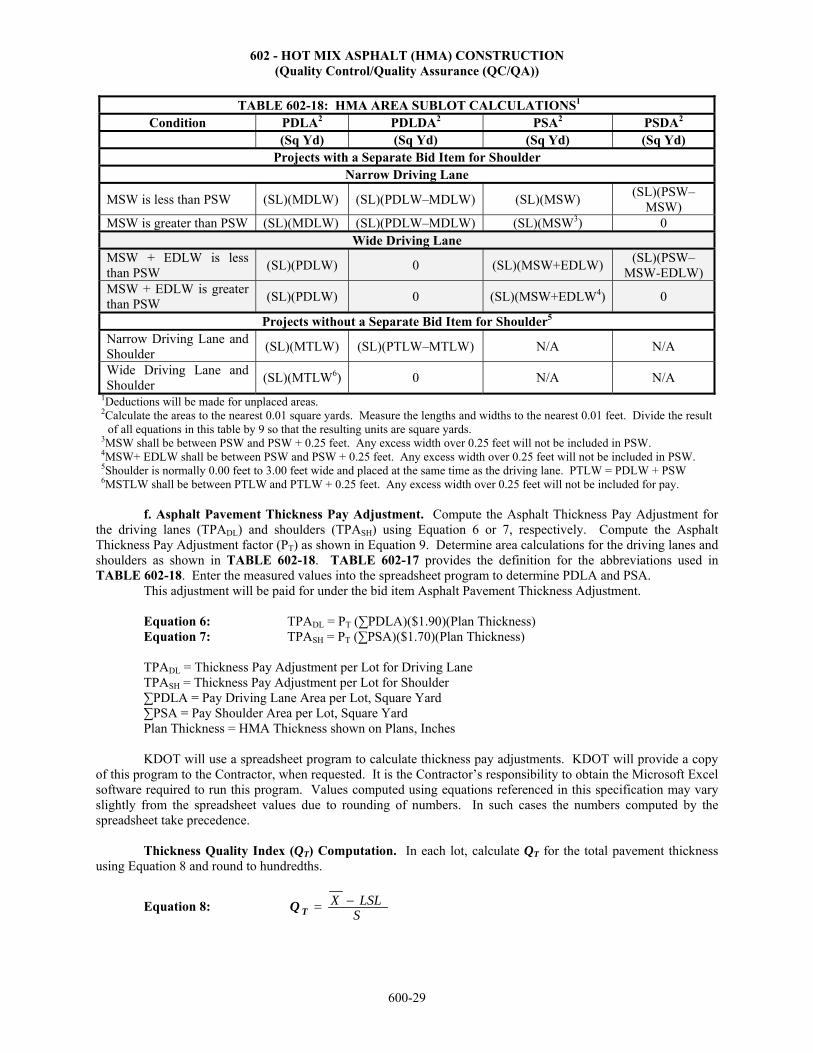
602 - HOT MIX ASPHALT (HMA) CONSTRUCTION (Quality Control/Quality Assurance (QC/QA))
600-29
TABLE 602-18: HMA AREA SUBLOT CALCULATIONS1 Condition PDLA2 PDLDA2 PSA2 PSDA2
(Sq Yd) (Sq Yd) (Sq Yd) (Sq Yd)Projects with a Separate Bid Item for Shoulder
Narrow Driving Lane
MSW is less than PSW (SL)(MDLW) (SL)(PDLW–MDLW) (SL)(MSW) (SL)(PSW–
MSW) MSW is greater than PSW (SL)(MDLW) (SL)(PDLW–MDLW) (SL)(MSW3) 0
Wide Driving LaneMSW + EDLW is less than PSW
(SL)(PDLW) 0 (SL)(MSW+EDLW) (SL)(PSW–
MSW-EDLW) MSW + EDLW is greater than PSW
(SL)(PDLW) 0 (SL)(MSW+EDLW4) 0
Projects without a Separate Bid Item for Shoulder5
Narrow Driving Lane and Shoulder
(SL)(MTLW) (SL)(PTLW–MTLW) N/A N/A
Wide Driving Lane and Shoulder
(SL)(MTLW6) 0 N/A N/A1Deductions will be made for unplaced areas. 2Calculate the areas to the nearest 0.01 square yards. Measure the lengths and widths to the nearest 0.01 feet. Divide the result
of all equations in this table by 9 so that the resulting units are square yards. 3MSW shall be between PSW and PSW + 0.25 feet. Any excess width over 0.25 feet will not be included in PSW. 4MSW+ EDLW shall be between PSW and PSW + 0.25 feet. Any excess width over 0.25 feet will not be included in PSW. 5Shoulder is normally 0.00 feet to 3.00 feet wide and placed at the same time as the driving lane. PTLW = PDLW + PSW 6MSTLW shall be between PTLW and PTLW + 0.25 feet. Any excess width over 0.25 feet will not be included for pay.
f. Asphalt Pavement Thickness Pay Adjustment. Compute the Asphalt Thickness Pay Adjustment forthe driving lanes (TPADL) and shoulders (TPASH) using Equation 6 or 7, respectively. Compute the Asphalt Thickness Pay Adjustment factor (PT) as shown in Equation 9. Determine area calculations for the driving lanes and shoulders as shown in TABLE 602-18. TABLE 602-17 provides the definition for the abbreviations used in TABLE 602-18. Enter the measured values into the spreadsheet program to determine PDLA and PSA.
This adjustment will be paid for under the bid item Asphalt Pavement Thickness Adjustment.
Equation 6: TPADL = PT (∑PDLA)($1.90)(Plan Thickness) Equation 7: TPASH = PT (∑PSA)($1.70)(Plan Thickness)
TPADL = Thickness Pay Adjustment per Lot for Driving Lane TPASH = Thickness Pay Adjustment per Lot for Shoulder ∑PDLA = Pay Driving Lane Area per Lot, Square Yard ∑PSA = Pay Shoulder Area per Lot, Square Yard Plan Thickness = HMA Thickness shown on Plans, Inches
KDOT will use a spreadsheet program to calculate thickness pay adjustments. KDOT will provide a copy of this program to the Contractor, when requested. It is the Contractor’s responsibility to obtain the Microsoft Excel software required to run this program. Values computed using equations referenced in this specification may vary slightly from the spreadsheet values due to rounding of numbers. In such cases the numbers computed by the spreadsheet take precedence.
Thickness Quality Index (QT) Computation. In each lot, calculate QT for the total pavement thickness using Equation 8 and round to hundredths.
Equation 8:SLSLX Q T

602 - HOT MIX ASPHALT (HMA) CONSTRUCTION (Quality Control/Quality Assurance (QC/QA))
600-30
X = Average total core length of all samples representing a lot, rounded to the nearest 0.1 inch. (Adjust core length before averaging, as shown in subsection 602.10b.) LSL = Lower specification limit for thickness. For driving lanes use 0.5 inch less than the total plan driving lane thickness shown on the typical section. For shoulders, use 0.8 inch less than the total plan shoulder thickness shown on the typical section. S = Sample standard deviation of the measured core lengths of all samples representing a lot and is calculated using equation (4) in Section 5.2.1 – Statistics, Part V, rounded to hundredths.
Use the computed QT to determine the thickness Percent Within Limits value (PWLT) by locating the QT in
the left column of the Percent Within Limits (PWL) Table in Section 5.2.1 - Statistics, Part V. Select the appropriate PWLT by moving across the selected QT row to the column representing the number of samples in the lot.
If the computed QT is a negative value, then the lot and all adjacent areas (full width of roadway) shall be overlaid as determined by the Engineer. After the lot has been overlaid, randomly select another core for each sublot, and calculate a new pay factor. For lots that have been entirely overlaid, the maximum pay factor is zero.
If the computed QT is greater than the largest QT shown in the PWL Table, a value of 100.00 is assigned as the PWLT for thickness.
For each lot and all lanes and shoulders, compute the thickness pay factor (PT) for the total pavement thickness using Equation 9 and round to nearest thousandth. No bonus will be paid for shoulders, thus use PT = 0.000 whenever PT calculates greater than 0.000 for shoulders.
Equation 9: 270.0100
30.0*)(
T
TPWL
P
g. Minimum Quantity of HMA for Square Yard Projects with "HMA Pavement" and HMA
Pavement Shoulder" Bid Items. For the total project, supply a minimum of 93% of Gmm required by the surface course of driving lanes and shoulders and the top base course of driving lanes and shoulder. Calculate the minimum quantity of those 2 mixes, individually as follows:
Equation 14: 42.7
)(G (T) (A) 0.93(Tons)Quantity Minimum
mm
A = Area in square yards for each of the mixes. T = Plan thickness in inches of surface course and the top base course of driving lanes and shoulders. Gmm = Theoretical maximum specific gravity equals the average Gmm value used in the first 5 lots or the average Gmm for ½ of the project (whichever is less) for the 4 mixes listed in “T” in Equation 14. Determine the average Gmm from the Excel worksheet titled "Density F & T Test Worksheet".
If this minimum quantity of surface course or base course is not placed, a deduction of $40 per ton will
apply to the quantity not placed for each mix. This will be paid using the bid item Contract Deduct which will be an item added to the contract. 602.11 MEASUREMENT AND PAYMENT a. "HMA Base", "HMA Surface" and "HMA Overlay" Bid Items. The Engineer will measure HMA Base, HMA Surface and HMA Overlay by the ton of material at the time of delivery to the road. Batch weights will not be allowed as a method of measurement unless all the following conditions are met:
the plant is equipped with an automatic printer system approved by the Engineer; the automatic printer system prints the weights of material delivered; and the automatic printer system is used in conjunction with an automatic batching and mixing control system
approved by the Engineer. Provide a weigh ticket for each load. Due to possible variations in the specific gravity or weight per cubic
foot of the aggregates, the tonnage used may vary from the proposal quantities and no adjustment in contract unit price will be made because of such variances.

602 - HOT MIX ASPHALT (HMA) CONSTRUCTION (Quality Control/Quality Assurance (QC/QA))
600-31
Payment for "HMA Base (*)(**)(***)", "HMA Surface (*)(**)(***)" and "HMA Overlay (*)(**)(***)" at the contract unit prices is full compensation for the specified work. Any pay adjustments will both be applied and the payment adjusted accordingly.
Sideroads, entrances and mailbox turnouts that are not shown in the Contract Documents that are to be surfaced shall be paid for at 1½ times the unit price for "HMA Surface (*)(**)(***)" or "HMA Base(*)(**)(***)".
b. "HMA Pavement" and "HMA Shoulder" Bid Items. The Engineer will measure HMA Pavementand HMA Pavement Shoulder by the square yard of the measured in-place material. All lifts, except the surface course, will be measured by the Contractor and verified by the Engineer. The Engineer will measure the surface course.
Measure each shoulder width, each driving lane width and sublot length separately. Measure the lengths (to the nearest 0.1 inch) a minimum of once per sublot. The location of the width measurements will be the same location as the mainline cores which were established using random numbers. Before the end of the next working day, type and submit to the Engineer, the Contractor’s individual measurements and the sum of the 2 driving lanes. Likewise, when the surface course is completed the Engineer will provide a typed copy of the surface course measurements to the Contractor before the end of the next working day.
If the driving lane and shoulder (measured from centerline) is less than 0.25 feet (per side) deficient, a deduction will be assessed. If the roadway is greater than 0.25 feet (per side) deficient, correction will be required. The correction will be proposed by the Contractor and must be approved by the Engineer. After satisfactory correction by the Contractor, the deduction for the narrow roadway will be eliminated for the areas corrected.
The Engineer will measure the sublot length and width (to the nearest 0.01 feet). Measure the width from the construction joint to the top of the slope of HMA pavement. Calculate the pay area for each lot to the nearest square yard. Unless the Engineer authorizes in writing to increase the area of HMA pavement, the Engineer will use dimensions shown in the Contract Documents and as measured in the field to calculate the final pay quantity. If the Engineer authorizes in writing to increase the area of HMA pavement or shoulder, the additional area will be measured and paid for as "HMA Pavement (#) (##)" or "HMA Pavement (#) Shoulder", respectively. The length will be measured horizontally along the centerline of each roadway or ramp.
Payment for "HMA Pavement (#) (##)" and "HMA Pavement (#) Shoulder" at the contract unit prices is full compensation for the specified work.
The Asphalt Pavement Thickness Adjustment and Asphalt Pavement Area Pay Adjustment will be entered on the Contractor’s Payment Vouchers (intermediates and final) after each lot of the surface course (driving lanes and shoulders) has been completed.
The Contractor will receive no additional compensation for overlaying or for removing and replacing areas of deficient thickness. Exploratory cores and cores taken to determine pavement thickness will not be measured for payment. The Engineer will apply a Contract Deduct for surface course (driving lanes and shoulders) and top base course (driving lanes and shoulders) mix not placed on the project as determined using Equation 14. The Contract Deduct will be computed by the spreadsheet and be an item added to the contract.
If the project has a large amount of grinding required for pavement smoothness, the Engineer may require the Contractor to cut cores after the grinding is complete. These cores will be used in the spreadsheet in place of the cores originally cut.
c. Emulsified Asphalt. The Engineer will measure emulsified asphalt used for tack by the ton. Paymentfor "Emulsified Asphalt" at the contract unit price is full compensation for the specified work.
d. Asphalt Core (Set Price). The Engineer will measure each asphalt core required by the Engineer tocalibrate the nuclear density gauges (typically 3 cores for each calibration). No payment will be made for cores deemed unsuitable for calibrating the nuclear density gauges. No payment will be made for cores taken at the Contractor’s option to determine density.
If during nuclear density dispute resolution, the Contractor’s test results are used for payment, each core taken will be measured for payment at 1 ½ times the Asphalt Core (Set Price). If KDOT’s test results are used for payment, then no payment for cores will be made for nuclear density dispute resolution.
Payment for "Asphalt Core (Set Price)" at the contract set unit price is full compensation for the specified work.
e. Material for HMA Patching (Set Price). When the Contractor is required to remove any existing basecourse, subgrade or surface course (unless damaged by the Contractor) and provisions are not made in the Contract

602 - HOT MIX ASPHALT (HMA) CONSTRUCTION (Quality Control/Quality Assurance (QC/QA))
600-32
Documents, the Engineer will measure the material used for repair and patching (either HMA-Commercial Grade or a specified mix on the project) separately, by the ton at the time of delivery to the road. The Engineer will not measure the quantity of material used in the repair of damage due to the Contractor’s negligence. The Engineer will measure HMA materials by the ton. For mixes containing Reclaimed HMA Pavement (RAP) or Recycled Asphalt Shingles (RAS), compute the HMA material contained in the RAP and RAS using the binder content determined from ignition oven testing. Maintain this information for materials tracking purposes. No separate payment for HMA material in RAP and RAS will be made. Combined gradation results will be used for acceptance in accordance with TABLE 602-1.
Payment for "Material for HMA Patching (Set Price)" at the contract set unit price includes all excavation, compaction of subgrade or subbase if required, disposal of waste material and all material (including emulsified asphalt for tack), all labor, equipment, tools, supplies, incidentals and mobilization necessary to complete the work. Pay adjustments will not be applied to this material.
f. Quality Control Testing (HMA). The Engineer will measure Quality Control Testing (HMA) performedby the Contractor on a per ton basis of HMA Surface, HMA Base, HMA Overlay and HMA Pavement placed on the project. No adjustment in the bid price will be made for overruns or underruns in the contract quantity. The bid price will constitute payment for all necessary mix design testing, field process control testing, the testing laboratory and all necessary test equipment.
The Engineer will not measure for payment Quality Control Testing (HMA) for the bid item Material for HMA Patching (Set Price).
Payment for "Quality Control Testing (HMA)" at the contract unit price is full compensation for the specified work.
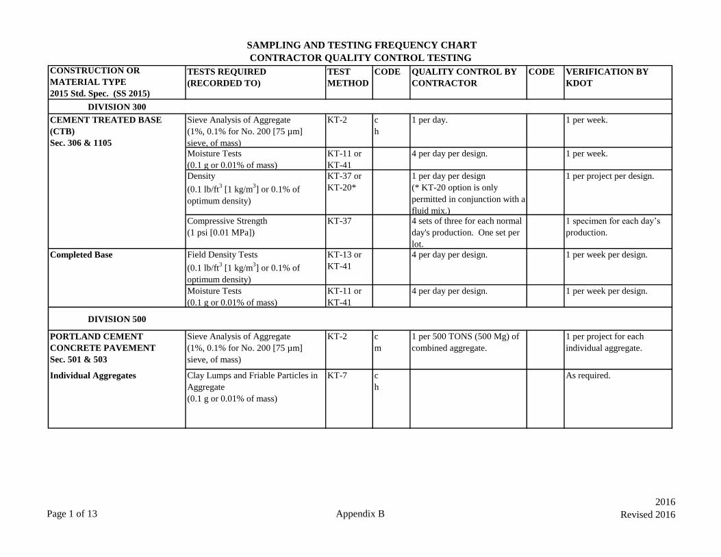
SAMPLING AND TESTING FREQUENCY CHART
CONTRACTOR QUALITY CONTROL TESTING
CONSTRUCTION OR
MATERIAL TYPE
2015 Std. Spec. (SS 2015)
TESTS REQUIRED
(RECORDED TO)
TEST
METHOD
CODE QUALITY CONTROL BY
CONTRACTOR
CODE VERIFICATION BY
KDOT
DIVISION 300
CEMENT TREATED BASE
(CTB)
Sec. 306 & 1105
Sieve Analysis of Aggregate
(1%, 0.1% for No. 200 [75 µm]
sieve, of mass)
KT-2 c
h
1 per day. 1 per week.
Moisture Tests
(0.1 g or 0.01% of mass)
KT-11 or
KT-41
4 per day per design. 1 per week.
Density
(0.1 lb/ft3 [1 kg/m
3] or 0.1% of
optimum density)
KT-37 or
KT-20*
1 per day per design
(* KT-20 option is only
permitted in conjunction with a
fluid mix.)
1 per project per design.
Compressive Strength
(1 psi [0.01 MPa])
KT-37 4 sets of three for each normal
day's production. One set per
lot.
1 specimen for each day’s
production.
Completed Base Field Density Tests
(0.1 lb/ft3 [1 kg/m
3] or 0.1% of
optimum density)
KT-13 or
KT-41
4 per day per design. 1 per week per design.
Moisture Tests
(0.1 g or 0.01% of mass)
KT-11 or
KT-41
4 per day per design. 1 per week per design.
DIVISION 500
PORTLAND CEMENT
CONCRETE PAVEMENT
Sec. 501 & 503
Sieve Analysis of Aggregate
(1%, 0.1% for No. 200 [75 µm]
sieve, of mass)
KT-2 c
m
1 per 500 TONS (500 Mg) of
combined aggregate.
1 per project for each
individual aggregate.
Individual Aggregates Clay Lumps and Friable Particles in
Aggregate
(0.1 g or 0.01% of mass)
KT-7 c
h
As required.
Page 1 of 13 Appendix B
2016
Revised 2016
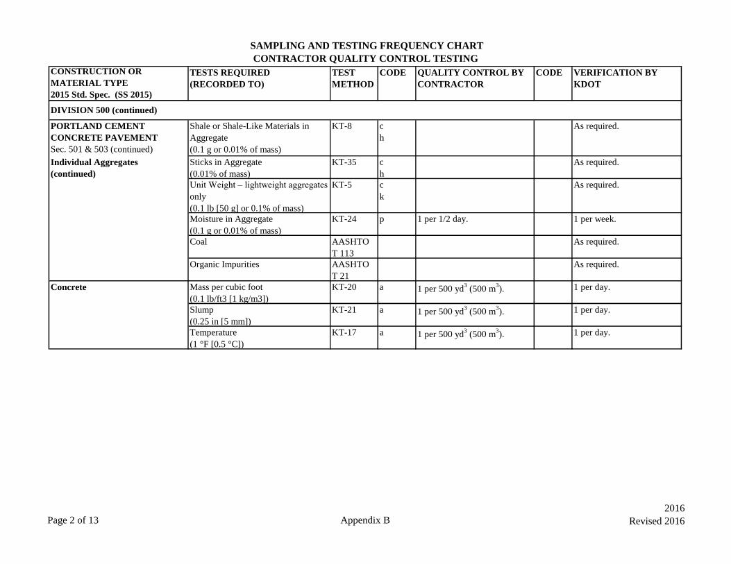
SAMPLING AND TESTING FREQUENCY CHART
CONTRACTOR QUALITY CONTROL TESTING
CONSTRUCTION OR
MATERIAL TYPE
2015 Std. Spec. (SS 2015)
TESTS REQUIRED
(RECORDED TO)
TEST
METHOD
CODE QUALITY CONTROL BY
CONTRACTOR
CODE VERIFICATION BY
KDOT
PORTLAND CEMENT
CONCRETE PAVEMENT
Sec. 501 & 503 (continued)
Shale or Shale-Like Materials in
Aggregate
(0.1 g or 0.01% of mass)
KT-8 c
h
As required.
Individual Aggregates
(continued)
Sticks in Aggregate
(0.01% of mass)
KT-35 c
h
As required.
Unit Weight – lightweight aggregates
only
(0.1 lb [50 g] or 0.1% of mass)
KT-5 c
k
As required.
Moisture in Aggregate
(0.1 g or 0.01% of mass)
KT-24 p 1 per 1/2 day. 1 per week.
Coal AASHTO
T 113
As required.
Organic Impurities AASHTO
T 21
As required.
Concrete Mass per cubic foot
(0.1 lb/ft3 [1 kg/m3])
KT-20 a 1 per 500 yd3 (500 m
3). 1 per day.
Slump
(0.25 in [5 mm])
KT-21 a 1 per 500 yd3 (500 m
3). 1 per day.
Temperature
(1 °F [0.5 °C])
KT-17 a 1 per 500 yd3 (500 m
3). 1 per day.
DIVISION 500 (continued)
Page 2 of 13 Appendix B
2016
Revised 2016

SAMPLING AND TESTING FREQUENCY CHART
CONTRACTOR QUALITY CONTROL TESTING
CONSTRUCTION OR
MATERIAL TYPE
2015 Std. Spec. (SS 2015)
TESTS REQUIRED
(RECORDED TO)
TEST
METHOD
CODE QUALITY CONTROL BY
CONTRACTOR
CODE VERIFICATION BY
KDOT
PORTLAND CEMENT
CONCRETE PAVEMENT
Sec. 501 & 503 (continued)
Concrete (continued)
Air Content
(0.25%)
KT-18 or
KT-19
a 1 per 500 yd3 (500 m
3) or
every 2 hours (mainline),
every 4 hours (other
slipformed pvmt), whichever is
more frequent.Determine the
air loss due to paving
operations once in the AM and
once in the PM. Determine the
difference between the air
content from concrete sampled
before the paver, and concrete
sampled behind the paver.
1 per day.
Density of Fresh Concrete
(0.1 lb/ft3 [1 kg/m
3])
KT-38 Initially, 1 complete transverse
profile, then 1 density per ½
day.
1 density per week.
Beams
(1 psi [1 kPa])
KT-22 &
KT-23
1 set of 3 as required for
opening to traffic.
1 set of 3 per week as
required for opening to
traffic.
Cores
(1 lbf [1 N], 0.01 in [1 mm], 1 psi
[0.01 MPa])
KT-49 As required in SS 2007 section
501.5g.
Thickness measurement and
compression test – 1 per lot.
DIVISION 500 (continued)
Page 3 of 13 Appendix B
2016
Revised 2016

SAMPLING AND TESTING FREQUENCY CHART
CONTRACTOR QUALITY CONTROL TESTING
CONSTRUCTION OR
MATERIAL TYPE
2015 Std. Spec. (SS 2015)
TESTS REQUIRED
(RECORDED TO)
TEST
METHOD
CODE QUALITY CONTROL BY
CONTRACTOR
CODE VERIFICATION BY
KDOT
PORTLAND CEMENT
CONCRETE PAVEMENT
Sec. 501 & 503 (continued)
Air Void Analyzer
(0.0001 in [0.001 mm])
KT-71 Prequalification of mix
required as per SS 2015 sec.
403.4.
1 test randomly during every
4 weeks of production.
Concrete (continued) Permeability
(0.01%, KT-73;
10 coulomb, AASHTO T 277;
nearest 0.1 kΩ-cm, KT-79
KT-73 or
AASHTO
T 277 or
KT-79
o 1 per mix design per project.
Profilograph KT-46 2 tracks per 12 ft (3.7 m) of
width for the full length of the
project.
At the Engineer’s discretion.
Vibrator Frequency
Per Standard Specifiction 154.2e
SS 154.2e Every 4 hours Daily
ON-GRADE CONCRETE
(OGCA)
See 5.6 Section 5.4.4 of this
manual.
DIVISION 600
HMA (Plant Mix) Sec. 602, 603,
611 & 1103
Individual Aggregates Sieve Analysis of Aggregate
(1%, 0.1% for No. 200 [75 µm]
sieve, of mass)
KT-2 c 1 per 1000 TONS (1000 Mg)
for each individual aggregate.
1 during the first 5000
TONS (5000 Mg) of HMA
produced for each individual Clay Lumps and Friable Particles in
Aggregate
(0.1 g or 0.01% of mass)
KT-7 c
h
As required.
Shale or Shale-Like Materials in
Aggregate
(0.1 g or 0.01% of mass)
KT-8 c
h
As required.
Sticks in Aggregate
(0.01% of mass)
KT-35 c
h
As required.
Uncompacted Void Content of Fine
Aggregate
(0.1%)
KT-50 l 1 on the first lot then 1 per
10,000 TONS (10,000 Mg) of
crushed gravel.
1 during the first 5000
TONS (5000 Mg) of HMA
produced.
DIVISION 500 (continued)
Page 4 of 13 Appendix B
2016
Revised 2016

SAMPLING AND TESTING FREQUENCY CHART
CONTRACTOR QUALITY CONTROL TESTING
CONSTRUCTION OR
MATERIAL TYPE
2015 Std. Spec. (SS 2015)
TESTS REQUIRED
(RECORDED TO)
TEST
METHOD
CODE QUALITY CONTROL BY
CONTRACTOR
CODE VERIFICATION BY
KDOT
HMA (Plant Mix) continued
Sec. 602, 603, 611 & 1103
Individual Aggregates (continued) Uncompacted Void Content of
Coarse Aggregate
(0.01%)
KT-80 l 1 on the first lot then 1 per
10,000 TONS (10,000 Mg) of
crushed gravel.
1 during the first 5000
TONS (5000 Mg) of HMA
produced.
Mineral Filler Supplement Sieve Analysis of Aggregate
(1%, 0.1% for No. 200 [75 µm]
sieve, of mass)
KT-2 c
h
1 per 250 TONS (250 Mg). 1 during the first 5000
TONS (5000 Mg) of HMA
produced.
Plasticity Tests
(0.01 g or 0.1% of mass)
KT-10 c
h
1 per 250 TONS (250 Mg).
Combined Aggregate Coarse Aggregate Angularity
(Determination of Crushed Particles
in Crushed Gravel)
(0.1% of mass)
KT-31 c
g
1 per lot 1 per week or 1 per 10,000
TONS (10,000 Mg).
Uncompacted Void Content of Fine
Aggregate
(0.1%)
KT-50 1 on the first lot then 1 per
10,000 TONS (10,000 Mg) of
combined aggregate.
1 during the first 5000
TONS (5000 Mg) of HMA
produced.
Sand Equivalent Test
(1%)
KT-55 f 1 per lot.
Flat or Elongated Particles
(1%)
KT-59 1 on the first lot.
Moisture Tests
(0.1 g or 0.01% of mass)
KT-11 1 per lot.
Asphalt Material Sampling KT-26 b
e
1 sample for every 3 loads.
(CMS = VER)
HMA Mixtures Percent Moisture in Mixture
(0.1 g or 0.01% of mass)
KT-11 1 per lot. 1 during the first 5000
TONS (5000 Mg) of HMA
produced.
DIVISION 600 (continued)
Page 5 of 13 Appendix B
2016
Revised 2016

SAMPLING AND TESTING FREQUENCY CHART
CONTRACTOR QUALITY CONTROL TESTING
CONSTRUCTION OR
MATERIAL TYPE
2015 Std. Spec. (SS 2015)
TESTS REQUIRED
(RECORDED TO)
TEST
METHOD
CODE QUALITY CONTROL BY
CONTRACTOR
CODE VERIFICATION BY
KDOT
HMA Mixtures (continued) Air Voids
(Va = 0.01%; Gmm & Gmb = 0.001)
KT-15,
KT-39,
KT-58, &
SF Manual
1 per sublot.
(See code n for Gmm)
j 1 per lot. [Compact split
sample on KDOT Gyratory
– 1 per week or every
15,000 TONS (15,000 Mg)]
Binder Content (by ignition)
(0.1 g or 0.01% of mass)
KT-57 1 per sublot. j 1 per lot.
Mix Gradation (after ignition)
(0.1 g or 0.01% of mass)
KT-34 1 per sublot. 1 per lot.
Moisture Damage to Mix (Modified
Lottman)
(0.1%)
KT-56 d 1 on first lot then 1 per week
or every 10,000 TONS
(10,000 Mg).
1 during the first 5000
TONS (5000 Mg) of HMA
produced. Performed by the Reclaimed Asphalt Pavement
(RAP)
Binder Content in RAP (by ignition)
(0.1 g or 0.01% of mass)
KT-57 1 during the first lot then 1 per
1000 TONS (1000 Mg) of
RAP.
j 1 during the first lot then 1
per 4000 TONS (4000 Mg)
of RAP.
RAP Gradation (after ignition)
(0.1 g or 0.01% of mass)
KT-34 1 per 1000 TONS (1000 Mg)
of RAP.
1 during the first 5000
TONS (5000 Mg) of HMA
Percent Moisture in RAP
(0.1 g or 0.01% of mass)
KT-11 1 per lot.
Recycled Asphalt Shingles (RAS) Binder Content in RAS (by ignition)
(0.1 g or 0.01% of mass)
KT-57 1 during the first lot then 1 per
1000 TONS (1000 Mg) of
RAP + RAS.
j 1 during the first lot then 1
per 4000 TONS (4000 Mg)
of RAP + RAS.
RAS Gradation (after ignition)
(0.1 g or 0.01% of mass)
KT-34 1 per 1000 TONS (1000 Mg)
of RAP + RAS.
1 during the first 5000
TONS (5000 Mg) of HMA
Percent Moisture in RAS
(0.1 g or 0.01% of mass)
KT-11 1 per lot.
HMA (Plant Mix continued)
Sec. 602, 603, 611 & 1103
DIVISION 600 (continued)
Page 6 of 13 Appendix B
2016
Revised 2016

SAMPLING AND TESTING FREQUENCY CHART
CONTRACTOR QUALITY CONTROL TESTING
CONSTRUCTION OR
MATERIAL TYPE
2015 Std. Spec. (SS 2015)
TESTS REQUIRED
(RECORDED TO)
TEST
METHOD
CODE QUALITY CONTROL BY
CONTRACTOR
CODE VERIFICATION BY
KDOT
Completed Road Work
Field Density Tests
(Use Cores or Nuclear Density
Gauge on all HMA roadway or
shoulder construction greater than or
equal to 1.5 inches)
Field Density - Cores or Nuclear
Density Gauge
(Gmb = 0.001; 0.1 lb/ft3 [1 kg/m
3] or
0.01% of Gmm)
KT-15 or
KT-32
i 10 tests per lot. i 5 companion tests per lot.
(Use approved rolling procedure and
Nuclear Density Gauge on all HMA
roadway or shoulder construction
less than 1.5 inches)
Field Density -Nuclear Density
Gauge
(Gmb = 0.001; 0.1 lb/ft3 [1 kg/m
3] or
0.01% of Gmm)
KT-32 i 10 Nuclear Gauge readings per
lot
Verify Approved Rolling
Procedure every 2 hours
Profilograph KT-46 2 tracks per 12 ft (3.7 m) of
width for the full length of the
project.
At the Engineer’s discretion.
Cold In-Place Recycle (CIR)
Sec. 604
Sampling Aggregate KT-1 2 per mile (1.5 km).
(Sieve according to
specification.)
k 1 per day.
Percent Retained on the #200
(75 µm) Sieve by Dry Screen
KT-4 2 per day.
Field Moisture Tests
(0.1 g or 0.01% of mass)
KT-32 Minimum 1 per day. Use
nuclear gauge w/o
correction. (Test before
overlay or seal.)
DIVISION 600 (continued)
HMA (Plant Mix continued)
Sec. 602, 603, 611 & 1103
Page 7 of 13 Appendix B
2016
Revised 2016

SAMPLING AND TESTING FREQUENCY CHART
CONTRACTOR QUALITY CONTROL TESTING
CONSTRUCTION OR
MATERIAL TYPE
2015 Std. Spec. (SS 2015)
TESTS REQUIRED
(RECORDED TO)
TEST
METHOD
CODE QUALITY CONTROL BY
CONTRACTOR
CODE VERIFICATION BY
KDOT
Cold In-Place Recycle (CIR)
Sec. 604
(continued)
Field Density
(Gmb = 0.001; 0.1 lb/ft3 [1 kg/m
3] or
0.01% of Gmm)
KT-32 3 locations per width laid
per mile (1.5 km) per lift.
Minimum of 1 per day.
Asphalt Material (Emulsion) Sampling KT-26 b
e
1 sample for every 3 loads. b
Lime Slurry Percent Solids of Lime Slurry KT-62 1 at beginning of project then
1 at each mix design change.
k
MICROSURFACING
Sec. 606 & 1109
Sieve Analysis of Aggregate
(1%, 0.1% for No. 200 [75 µm]
sieve, of mass)
KT-2 c 1 per 250 TONS (250 Mg) for
each individual aggregate.
1 per day.
MICROSURFACING (continued)
Sec. 606 & 1109
Moisture Tests
(0.1 g or 0.01% of mass)
KT-11 3 per day. 1 per day.
Emulsified Asphalt KT-26 1 per project. k
Sampling Cement KT-29 1 per project. k
Percent Crushed Particles in Crushed
Gravel
(0.1%)
KT-31 1 per project. k
Uncompacted Void Content of Fine
Aggregate
(0.1%)
KT-50 1 per project. k
Sand Equivalent Test
(1%)
KT-55 1 per project. k
ULTRATHIN BONDED
ASPHALT SURFACE (UBAS)
Sec. 613 & 1103
Individual Aggregates Sieve Analysis of Aggregate
(1%, 0.1% for No. 200 [75 µm]
sieve, of mass)
KT-2 c
h
1 per 1000 TONS (1000 Mg)
for each individual aggregate.
1 per project per individual
aggregate.
Uncompacted Void Content of Fine
Aggregate
(0.1%)
KT-50 l 1 on the first lot then 1 per
10,000 TONS (10,000 Mg) of
crushed gravel.
1 per project.
DIVISION 600 (continued)
Page 8 of 13 Appendix B
2016
Revised 2016

SAMPLING AND TESTING FREQUENCY CHART
CONTRACTOR QUALITY CONTROL TESTING
CONSTRUCTION OR
MATERIAL TYPE
2015 Std. Spec. (SS 2015)
TESTS REQUIRED
(RECORDED TO)
TEST
METHOD
CODE QUALITY CONTROL BY
CONTRACTOR
CODE VERIFICATION BY
KDOT
ULTRATHIN BONDED
ASPHALT SURFACE (UBAS)
Sec. 613 & 1103 (continued)
Mineral Filler Supplement Sieve Analysis of Aggregate
(1%, 0.1% for No. 200 [75 µm]
sieve, of mass)
KT-2 c
h
1 per 250 TONS (250 Mg). 1 per project.
Plasticity Tests
(0.01 g or 0.1% of mass)
KT-10 c
h
1 per 250 TONS (250 Mg). 1 per project.
Combined Aggregate Coarse Aggregate Angularity
(0.1% of mass)
KT-31 c
g
h
1 per lot of combined
aggregate
1 per week or 1 per 10,000
TONS (10,000 Mg).
Uncompacted Void Content of Fine
Aggregate
(0.1%)
KT-50 f 1 on the first lot then 1 per
10,000 TONS (10,000 Mg) of
combined aggregate.
1 per project.
Sand Equivalent Test
(1%)
KT-55 f 1 per lot. 1 per project.
Moisture Tests
(0.1 g or 0.01% of mass)
KT-11 1 per 2000 TONS (200 Mg) of
combined mix.
1 per project.
Asphalt Material Sampling KT-26 b
e
1 sample for every 3 loads.
(CMS = VER)
HMA Mixtures Percent Moisture in Mixture
(0.1 g or 0.01% of mass)
KT-11 1 per 2000 TONS (200 Mg) of
combined mix.
1 per project.
Theoretical Maximum Specific
Gravity (Rice)
(Gmm = 0.001)
KT-39 n 1 per sublot. 1 per lot.
Binder Content (by ignition)
(0.1 g or 0.01% of mass)
KT-57 1 per sublot. j 1 per lot.
Mix Gradation (after ignition)
(0.1 g or 0.01% of mass)
KT-34 1 per sublot. 1 per lot.
DIVISION 600 (continued)
Page 9 of 13 Appendix B
2016
Revised 2016

SAMPLING AND TESTING FREQUENCY CHART
CONTRACTOR QUALITY CONTROL TESTING
CONSTRUCTION OR
MATERIAL TYPE
2015 Std. Spec. (SS 2015)
TESTS REQUIRED
(RECORDED TO)
TEST
METHOD
CODE QUALITY CONTROL BY
CONTRACTOR
CODE VERIFICATION BY
KDOT
Individual Aggregates Sieve Analysis of Aggregate
(1%, 0.1% for No. 200 [75 µm]
sieve, of mass)
KT-2 c 1 per 1000 TONS (1000 Mg)
for each individual aggregate.
1 during the first 5000
TONS (5000 Mg) of HMA
produced for each individual Clay Lumps and Friable Particles in
Aggregate
(0.1 g or 0.01% of mass)
KT-7 c
h
As required.
Shale or Shale-Like Materials in
Aggregate
(0.1 g or 0.01% of mass)
KT-8 c
h
As required.
Sticks in Aggregate
(0.01% of mass)
KT-35 c
h
As required.
Mineral Filler Supplement Sieve Analysis of Aggregate
(1%, 0.1% for No. 200 [75 µm]
sieve, of mass)
KT-2 c
h
1 per 250 TONS (250 Mg). 1 during the first 5000
TONS (5000 Mg) of HMA
produced.
Plasticity Tests
(0.01 g or 0.1% of mass)
KT-10 c
h
1 per 250 TONS (250 Mg).
Combined Aggregate Sand Equivalent Test
(1%)
KT-55 f 1 per lot.
Flat or Elongated Particles
(1%)
KT-59 1 on the first lot.
Moisture Tests
(0.1 g or 0.01% of mass)
KT-11 1 per lot.
Asphalt Material Sampling KT-26 b
e
1 sample for every 3 loads.
(CMS = VER)
HMA Mixtures Percent Moisture in Mixture
(0.1 g or 0.01% of mass)
KT-11 1 per lot. 1 during the first 5000
TONS (5000 Mg) of HMA
produced.
DIVISION 600 (continued)
HMA Base [Reflective Crack Interlayer RCI)] Sec. 614
Page 10 of 13 Appendix B
2016
Revised 2016
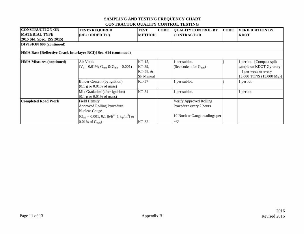
SAMPLING AND TESTING FREQUENCY CHART
CONTRACTOR QUALITY CONTROL TESTING
CONSTRUCTION OR
MATERIAL TYPE
2015 Std. Spec. (SS 2015)
TESTS REQUIRED
(RECORDED TO)
TEST
METHOD
CODE QUALITY CONTROL BY
CONTRACTOR
CODE VERIFICATION BY
KDOT
HMA Mixtures (continued) Air Voids
(Va = 0.01%; Gmm & Gmb = 0.001)
KT-15,
KT-39,
KT-58, &
SF Manual
1 per sublot.
(See code n for Gmm)
j 1 per lot. [Compact split
sample on KDOT Gyratory
– 1 per week or every
15,000 TONS (15,000 Mg)]
Binder Content (by ignition)
(0.1 g or 0.01% of mass)
KT-57 1 per sublot. j 1 per lot.
Mix Gradation (after ignition)
(0.1 g or 0.01% of mass)
KT-34 1 per sublot. 1 per lot.
Completed Road Work Field Density
Approved Rolling Procedure
Nuclear Gauge
(Gmb = 0.001; 0.1 lb/ft3 [1 kg/m
3] or
0.01% of Gmm) KT-32
Verify Approved Rolling
Procedure every 2 hours
10 Nuclear Gauge readings per
day
DIVISION 600 (continued)
HMA Base [Reflective Crack Interlayer RCI)] Sec. 614 (continued)
Page 11 of 13 Appendix B
2016
Revised 2016

SAMPLING AND TESTING FREQUENCY CHART
QUALITY CONTROL/QUALITY ASSURANCE SPECIFICATIONS
CODE
a
b Sampled by the district field personnel, or contractor and tested at KDOT Central Materials Laboratory (Materials and Research Center).
c
d
e
f
g
h
i For small lots [lots with less than 1,000 tons (1,000 Mg)], the number of tests may be reduced (see special provision).
j Provide access to Contractor owned forced air ignition furnace, ovens, and Superpave Gyratory compactor, as required, for the Sate Inspector to
perform verification tests.
INSTRUCTION
Specification compliance will be determined on a producer basis not on a project basis. Producer and product testing frequency is maintained in
CMS. Start with one in three loads, then generally, the sampling frequency will be reduced to one sample per six loads and then per twelve loads if
test results determined by the Department show satisfactory compliance of the material with the specifications.
Determine the Sand Equivalent (SE) value on the combined virgin aggregates on the first lot of production and then frequency may be reduced to
one test per week provided the SE value exceeds the minimum specified value by five (5) percentage points. The frequency may be reduced to one
test per two weeks provided the SE value exceeds the minimum specified value by 25 percentage points. When any test (including verification and
assurance) shows the SE value to be less than five (5) percentage points above the specified minimum value then the testing frequency will revert
to one per lot until two consecutive tests exceed the minimum specified value by five (5) percentage points.
All aggregate types except siliceous gravels and steel slag will be considered to have at least two crushed faces on 100% of the aggregate particles.
For mixes containing crushed or uncrushed siliceous gravels or steel slag, determine the Coarse Aggregate Angularity (CAA) value of the
combined virgin aggregate of the first lot of production. After three consecutive passing tests, the frequency may be reduced to one per three lots
or one per week. If any of the quality control or verification tests fail, the frequency will revert to one per lot until the above criteria for reduced
frequency is met.
If during the determination of individual aggregate gradation, clay lumps and soft or friable particles, shale or shale-like particles, or sticks are
found then perform KT-7, KT-8, and KT-35, respectively, at such frequencies as jointly deemed necessary by the Contractor and the District
Materials Engineer.
The contractor may reduce the sampling and testing frequency to one test per 1,000 yd3 (1,000 m
3) provided the first two tests each day show
compliance with the specification requirements.
The aggregate producer’s tests may be used for quality control purposes if the tests were performed by an appropriately certified technician. In
such cases, the contractor shall perform testing as necessary to determine the degrading effects of hauling and stockpiling on the individual
aggregates. For CTB, the minimum testing frequency shall be every 4,000 Tons (4,000 Mg).
At least one Modified Lottman test is required weekly. When more than 10,000 Tons (10,000 Mg) of production occurs in a week, then run additional
tests to meet the requirement of 1 test per 10,000 Tons (10,000 Mg).
Page 12 of 13 Appendix B 2016

SAMPLING AND TESTING FREQUENCY CHART
QUALITY CONTROL/QUALITY ASSURANCE SPECIFICATIONS
CODE
k
l
m
n If more than one test is performed on the sample, use the average value.
o Verification method must be the same test method as used for mix design approval.
p
GENERAL NOTES
For a better explanation of metric (SI) units, see section 5.9, “Sampling and Test Methods Forward”, of this manual.
All samples will be taken from the place of incorporation into the project unless otherwise noted.
For QUALITY CONTROL BY CONTRACTOR, CMS uses ACI or ACC unless otherwise noted. For VERIFICATION BY KDOT, CMS uses VER
unless otherwise noted. For INDEPENDENT ASSURANCE BY KDOT, CMS uses ASW (Assurance Witness), ASR (Assurance Replicate), and
ASP (Assurance Split) unless otherwise noted (see section 5.4.2 of this manual).
Engineer’s discretion. Frequency of tests shall be agreed upon by the Field Engineer and the District Materials Engineer. Frequency will be
governed by field conditions. Written documentation of the agreed upon testing frequency shall be included in the project records.
This testing of crushed gravel is only needed to confirm that 35% or less natural sand is used in the traveled way mixes. If 95% or more of crushed
gravel is retained on the #8 (2.65 mm) sieve, then the material must have a minimum Uncompacted Void Content of Coarse Aggregate (UVA)
value of 45 when tested in accordance with KT-80. Testing will be the same frequency as KT-50. Do not use material with a UVA value less than
The contractor may reduce the sampling and testing frequency to one test per 2,000 Tons (2,000 Mg) provided the first ten tests show compliance
with the specification requirements.
Frequency may be reduced to 1 pre-production verification test per day provided the following are met: 1) Handheld moisture meter is used at
least once per every 50 cubic yards of production. 2) The meter has an accuracy of ±0.5% of the pre-production verification test. 3) Moistures
obtained from the meter are used to adjust batch-to-batch moisture corrections.
All sampling and testing frequencies listed are minimums. Additional quality control, verification, and assurance tests will be performed, when
necessary, to provide effective control the work. When any quality control test result fails to comply with the specification requirements then the next
sublot of production after obtaining the failing test results will be sampled and tested, regardless of any lesser frequency specified in this appendix.
For the Construction Management System (CMS), Acceptance Sampling and Tests have been divided into two sections. Items called “ACC” will be
Acceptance Tests and will have a quantity assigned. Items called “ACI” will be Acceptance Information Tests and they will normally have a quantity
assigned, but not for payment. “ACC” tests make the assignment of tested materials to the contract or mix plant. “Type Insp” must = “ACC” when
assignment of a pay quantity is being made. “ACI” when recording test values for additional acceptance information.
INSTRUCTION
Page 13 of 13 Appendix B 2016