Embed Size (px)
Citation preview

1
Superconducting Magnets for Future Electron-Ion Collider
Yuhong ZhangThomas Jefferson National Accelerator Facility, USA
Mini-workshop on Accelerator, IAS, HKUST, Hong Kong, January 18-19, 2018

2
Outline
• Introduction
• SC Magnets for Ion Rings
• SC Magnets for Interaction Regions
• Summary
DIS2016, Hamburg
Acknowledgement
Tim Michalski (JLab), Peter McIntyre (Texas A&M Univ.),
Brett Parker (BNL), Alexander Kovalenko (Dubna)

3
Introduction
• An electron-ion Collider (EIC) is likely the next major US facility to
be built for nuclear science research – QCD frontier– Recommended by Nuclear Science Advisory Committee Long Range Plan 2015
– National Academy of Science Review underway (last milestone for DOE approval)
– Construction may start as early as 2022, likely cost at $1.5B
• Two DOE Labs (BNL & JLab) have proposed to host this collider– BNL eRHIC has proton/ion beams, need an electron beam (and an electron facility)
– JLab JLEIC has an electron beam, need proton/ion beams (and an ion complex)
• Presently, two teams are focused on design optimization, value
engineering and accelerator R&D
• EIC needs superconducting magnets– IR magnets: for both eRHIC and JLEIC
– Ring magnets: for JLEIC ion booster and collider
– Not pushing for new technology frontier, rather for better quality and cost efficient
(value engineering)

4
Two Labs Like to Host the US EIC
• Based on RHIC and its injector complex
– polarized proton and 3He, up to 250 GeV/u
– other all-stripped ions, up to gold 100 GeV/u
• Add a polarized electron beam up to 18 GeV
– A storage ring (ring-ring design)
– A full energy electron injector
• Based on CEBAF recirculated SRF linac
– polarized electron beam up to 12 GeV,
• Add ion injector and two storage rings
(ring-ring design)
– Polarized proton, deuteron and 3He
– Up to 100 GeV/u
BNL JLab
Has polarized proton & heavy ion beams
Needs a polarized electron beam
Has a polarized electron beam
Needs a proton/ion beam
eRHIC
CEBAF

5
Superconducting Magnets for EIC
• Hadron ring magnets for JLEIC only– Modest field for (present baseline) phase 1: 3 T Super-ferric, cost efficient
– Medium field for upgrade or phase 1 (alternate): 6 to 12 T, high CM energy reach
– Booster ring SC magnets need fast ramp (~0.3 T/s)
• IR magnets for both eRHIC and JLEIC– High field: up to 9 T
– Large aperture, high field quality
– Radiation resistance
• Solenoids for cooling and spin rotators
– Modest field strength, up to 6 T

6
JLEIC Ion Booster and Collider Ring Magnets
• A medium energy ion collider ring, not for energy frontier
• Cost efficiency is the primary goal (make the machine affordable)
• The booster and collider ring magnet field is 3 T
• The booster ring magnet needs fast ramp (~0.33 T/s 0 to 3 T in 10 s)
• The leading choice of technology is super-ferric magnet for baseline
– Cost efficient, similar to warm magnets
– Fast ramping, closed to warm magnets
ion sources
SRF linac
booster
collider
ring
cooling
cooling
Length (m) Max. energy (GeV) Max. dipole field (T)
SRF linac 0.2
booster ~275 7.9 / 12 3
collider ring ~2250 100 / 200 / 266 3 / 6 / 8.3

7
NICA / Nuclotron Super-ferric Magnets
• A low energy ion-ion collider,
circumference: 251.5 m
• 96 dipoles, 64 quads, beam pipe
aperture 55 x 110 mm
• Accelerated and extracted
particles from p to Xe
Kovalenko, Dubna

8
Dubna Hollow SC Cable
Kovalenko, Dubna
9
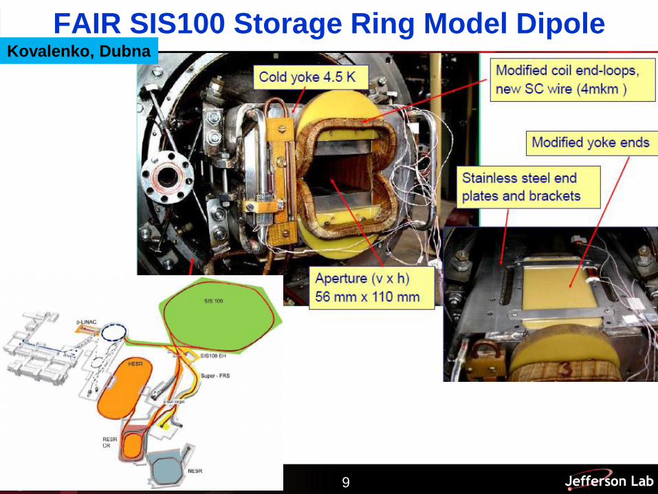
FAIR SIS100 Storage Ring Model DipoleKovalenko, Dubna

10
FAIR SIS100 Full Size Prototype
Straight dipole
B x Leffective T m 5.818
B T 2.11
Leffective m 2.756
Lyoke m 2.696
Bending angle deg 3
Radius of curvature m 47.4
Aperture mm 130 x 60
Quadrupole
B’ x Leffective T 35
B’ T/m 32
Leffective m 1.1
Estimated Lyoke m 1
Aperture mm 135 x 65
Manufactured and tested at JINR, DubanKovalenko, Dubna
11
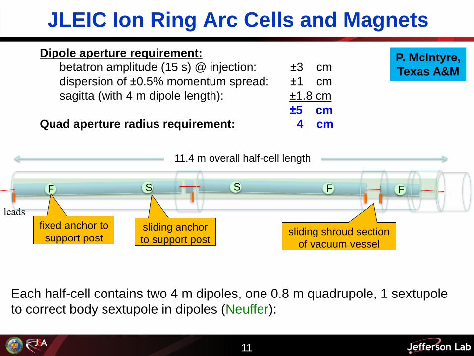
JLEIC Ion Ring Arc Cells and Magnets
Dipole aperture requirement:
betatron amplitude (15 s) @ injection: ±3 cm
dispersion of ±0.5% momentum spread: ±1 cm
sagitta (with 4 m dipole length): ±1.8 cm
±5 cm
Quad aperture radius requirement: 4 cm
Each half-cell contains two 4 m dipoles, one 0.8 m quadrupole, 1 sextupole
to correct body sextupole in dipoles (Neuffer):
F FFS S
11.4 m overall half-cell length
leads
fixed anchor to
support postsliding anchor
to support postsliding shroud section
of vacuum vessel
P. McIntyre,
Texas A&M

12
JLEIC Arc Dipole Design
The biggest challenge is to
create a 10 cm x 6 cm aperture
with the field quality needed for
high-luminosity collisions with
long luminosity lifetime –
dynamic aperture
0
5
10
15
20
0 2 4 6 8
I (k
A)
B (T)
Load Lines
NbTi short sample @ 4.5K
Bmax in coil
Bbore
short sample in coil
short sample in bore
Multipoles vs. field and load lines for MEIC dipole design.
P. McIntyre,
Texas A&M

13
JLEIC e-p Luminosity
100 GeV CM
115 GeV CM
140 GeV CM
Baseline
1034
2x1034
LHC SC
magnet
If it were feasible and affordable to make 6 T dipoles for the ion ring,
Maximum c.m. energy would increase by 40%; maximum luminosity would double.
5x1034

14
High Field (4 to 6 T) SC Magnets for JLEIC
• Hollow SC cables can be applied to the design and
construction of a (fast-ramping) 4 to 6 T dipoles
• Cosine θ style of magnet should be used
• For 6 to 6.5 T dipoles, use double-layer coil: a hollow
cable for inner layer, and Rutherford one for outer layer
4 T Cosine θ-style dipole with 2-4 T/s ramping rate
Kovalenko, Dubna

15
eRHIC Ring-Ring IR Layout
15
• 4.5 m detector space with crab crossing.
• Magnets quite different forward/rear due to physics requirements.
22 mrad total crossing angle

16
EIC IR Magnet Challenges
• Magnet Zoo: Just within ±20m of the IP we need 12 different styles of
superconducting magnets, most of which require closely spaced, double
apertures or low-field shielded regions.
– We want to avoid having to create unique tooling for each style.
• Large Aperture/Strong Field: A few of these magnets, i.e. on the
forward hadron side, must have very large apertures with relatively strong
quad gradients or strong dipole guide fields.
– Large coil fields/coil dimensions make external field shielding difficult.
– We should consider a range of coil and yoke topologies/schemes.
– We can benefit greatly by investing in shielding R&D (test facility).
• Monster Size: Even when we can use a “traditional solution for
magnetic shielding,” i.e. cutting holes in magnetic yokes to get reduced field
regions, some of the resulting yokes are monster sized.
– With limited resources, we must then carefully consider what R&D
prototypes are needed to validate performance goals (test facility).
B. Parker, BNL

17
eRHIC Magnet R&D Accomplishments
and Work Presently In Progress
• Have successfully upgraded Direct Wind machine to handle 1.6 mm cable for more than
twice capacity of the previous 1 mm cable (i.e. design with single strand wire and 1
mm or 1.6 mm cable).
– Now able to make large diameter coils with half as many cable layers.
• The dipole Sweet Spot coil nearing its completion has coil sizes comparable
to the Ring-Ring requirements and the prototype is designed to be operated
at even higher field.
– So we gain direct experience with large coils and 1.6 mm dia. cable.
– For the R&D prototype, inner/outer coils independently powered; we can
run in both Sweet Spot and the active cancellation configurations.
• We can provide a wide range of field strengths and varieties of field
configurations over the “Sweet Spot test region.”
– Opportunity to test passive magnetic/superconducting shield designs as
well as Direct Wound, corrector-like active compensation schemes.
17
B. Parker, BNL

18
Q1PF, First Forward Side Proton Quad18
3D End
View
• Q1PF, active external field cancelation coil.
• 90 T/m gradient, clear bore is 86 mm ID.
• Peak field about 4.5 T with essentially zero external
field outside body of the bare coil.
• Small cancellation undershoot/overshoot near
the coil ends is handled via the use of a thin
passive magnetic shield.
3D calculation done for
bare coils, run in series.
B. Parker, BNL

19
B0 Spectrometer Dipole Concept19
(m)
(m)
(m)
• B0, a Superferric C-magnet.
• 1.7 T Field, 1.3 m long.
• Gives access for detectors.
• Use a Direct Wind dipole cancel
coil to buck most of main f ield and
then use passive shielding inside.
x (mm)
Y (
mm
)
B0 Shielded Region Detailed View
Cancel coil keeps inner passive
shield from saturating
Passive shields Coil
Model by H. Witte
B. Parker, BNL
20
Summary
• EIC Will be the next big machine for US and for QCD research
• Jefferson Lab needs a new ion complex, which requires low to
medium field SC magnets for ion rings, however, low cost is the key.
• SC magnets for interaction region for both eRHIC and JLEIC are
challenging
• Some R&D for EIC rings and interaction region were initiated and in
progress
• For more information of EIC accelerator design and R&D
– JLEIC Accelerator Collaboration Meetings (5, 2015, 2016, 2017)
– EIC Accelerator Collaboration Meeting 2017
– All talks on the web

21


![Chapter 10 Superconducting Solenoid Magnets · Chapter 10 Superconducting Solenoid Magnets 10.1 Introduction TheNeutrinoFactory[1],[2],[3],beyondapproximately18mfromthetarget,requires](https://img.dokumen.tips/doc/110x75/5ec528158b55b07603639677/chapter-10-superconducting-solenoid-magnets-chapter-10-superconducting-solenoid.jpg)