Embed Size (px)
Citation preview
Superconducting Magnet R&Dfor the High Intensity Muon
Beam Productionin the COMET Experiment
Makoto YOSHIDAKEK IPNS Cryo-Group
IPNS SeminarOct. 14th, 2011
Contents
The COMET experimentSuperconducting magnet for COMETR&D status and prospects

Searches for Charged Lepton Mixing
Lepton flavor violation Beyond standard modelMuon plays important role in the searches
Low mass High statistics Long life easy to handle
KL0 → μe
K+ → πμe
μA→eA
μ → eee
μ→ eγ
1940
2000
1950
1970
1980
1990
1960
10-14
10-12
10-10
10-8
10-6
10-4
10-2
Bra
nchi
ng R
atio
Year10-16
μ e γ<2.4x10⁻¹²(MEG2010) O(10-13)
μ N e N1/400 (Al) of μ e γAwaiting searches for Br<10-16
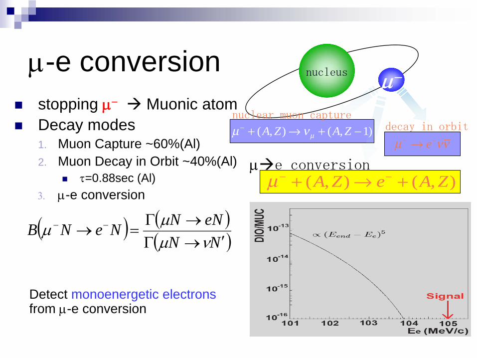
μ-e conversionstopping μ− Muonic atomDecay modes1. Muon Capture ~60%(Al)2. Muon Decay in Orbit ~40%(Al)
τ=0.88sec (Al)3. μ-e conversion
nucleus μ−
μ νμ− + → + −( , ) ( , )A Z A Z 1
nuclear muon capturedecay in orbit
μ νν− −→ e
μ− −+ → +( , ) ( , )A Z e A Zμ e conversion
( ) ( )( )NN
eNNNeNB′→Γ
→Γ=→ −−
νμμμ
Detect monoenergetic electrons from μ-e conversion
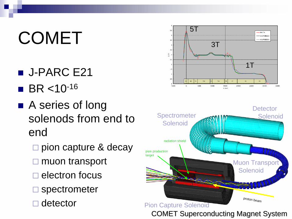
COMET
J-PARC E21BR <10-16
A series of long solenods from end to end
pion capture & decaymuon transportelectron focusspectrometerdetector Pion Capture Solenoid
Muon TransportSolenoid
SpectrometerSolenoid
DetectorSolenoid
proton beam
pion productiontarget
radiation shield
COMET Superconducting Magnet SystemCOMET Superconducting Magnet System
5T
3T
1T


Requirements on Muon Beam
Pulsed beamBunch spacing ~muon lifecan mask prompt BG
High intensity negative muon beamBr<10-16 1018 μ−
1011 μ−/sec for 2 year operationLow energy muons
<~70MeV/cto form muonic atomsto avoid Decay-in-Flight BG

COMET@J-PARC
Pulsed protons by slow extraction from MR8GeV x 5~7microAProton extinction <10-9
O(10-7)x10-6
J‐PARCJ‐PARC
1.8
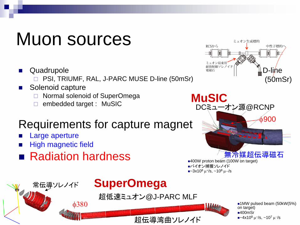
Muon sourcesQuadrupole
PSI, TRIUMF, RAL, J-PARC MUSE D-line (50mSr)Solenoid capture
Normal solenoid of SuperOmegaembedded target : MuSIC
Requirements for capture magnetLarge apertureHigh magnetic field
Radiation hardness
MuSICDCミューオン源@RCNP
無冷媒超伝導磁石
φ900
SuperOmega超低速ミュオン@J-PARC MLF
常伝導ソレノイド
超伝導湾曲ソレノイド
φ380
400W proton beam (100W on target) パイオン捕獲ソレノイド~3x10⁸ μ+/s, ~108 μ−/s
1MW pulsed beam (50kW(5%) on target)400mSr~4x10⁸ μ+/s, ~107 μ−/s
D-line(50mSr)
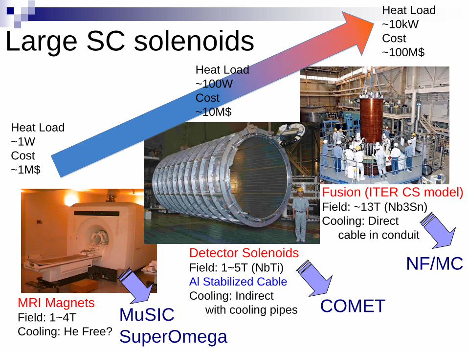
Large SC solenoids
Heat Load~1WCost~1M$
Heat Load~10kWCost~100M$
MRI MagnetsField: 1~4TCooling: He Free?
Detector SolenoidsField: 1~5T (NbTi)Al Stabilized CableCooling: Indirect
with cooling pipes
Fusion (ITER CS model)Field: ~13T (Nb3Sn)Cooling: Direct
cable in conduit
Heat Load~100WCost~10M$
COMETMuSICSuperOmega
NF/MC

Al-stabilized superconductor
NbTi Rutherford cable with aluminum stabilizer“TRANSPARENT” to radiation
Less nuclear heating
Doped, cold-worked aluminumGood residual resistance
RRR~500 (ρ0=0.05nΩm@4K)Good yield strength
85MPa@4K
COMET design valueSize: 4.7x15mmOffset yield point of Al@4K: >85MPaRRR@0T: >500Al/Cu/SC: 7.3/0.9/114 SC strands: 1.15mm dia.
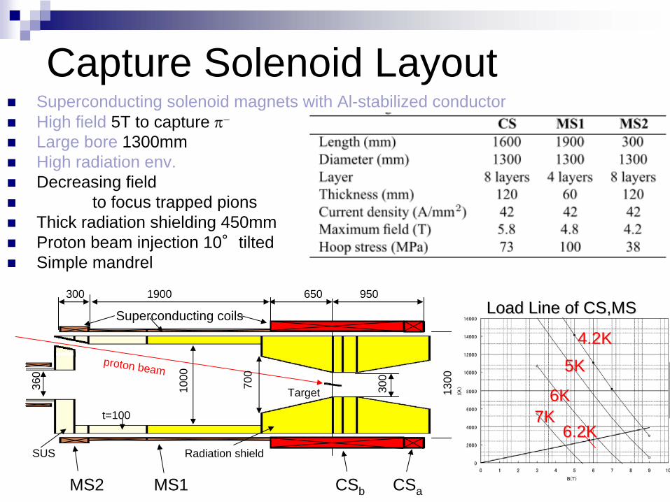
Capture Solenoid LayoutSuperconducting solenoid magnets with Al-stabilized conductorHigh field 5T to capture π−
Large bore 1300mmHigh radiation env.Decreasing field
to focus trapped pionsThick radiation shielding 450mmProton beam injection 10°tiltedSimple mandrel
proton beam
1300
9501900300 650
300
700
1000
360
t=100
Radiation shieldSUS
Target
Superconducting coils
CSbMS1MS2 CSa
6.2K6.2K
Load Line of CS,MSLoad Line of CS,MS
6K6K
5K5K4.2K4.2K
7K7K
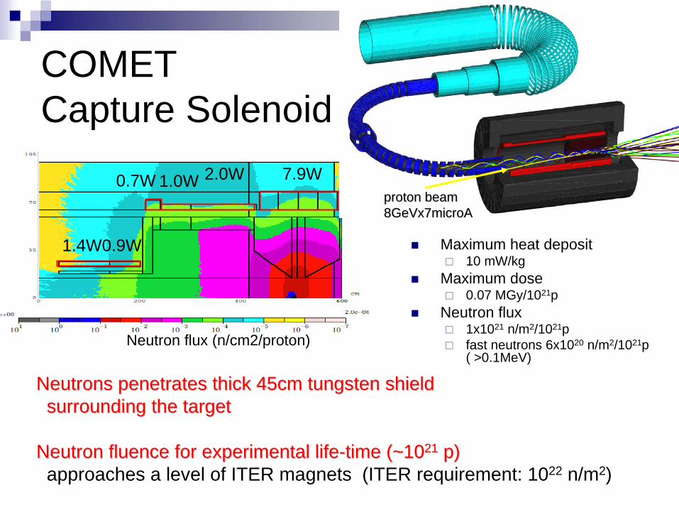
COMETCapture Solenoid
7.9W2.0W1.0W0.7W
0.9W1.4W
Neutron flux (n/cm2/proton)
Maximum heat deposit10 mW/kg
Maximum dose0.07 MGy/1021p
Neutron flux1x1021 n/m2/1021pfast neutrons 6x10²⁰ n/m2/1021p ( >0.1MeV)
Neutrons penetrates thick 45cm tungsten shieldNeutrons penetrates thick 45cm tungsten shieldsurrounding the targetsurrounding the target
Neutron fluence for experimental lifeNeutron fluence for experimental life--time (~10time (~102121 p)p)approaches a level of ITER magnets (ITER requirement: 1022 n/m2)
proton beamproton beam8GeVx7microA8GeVx7microA
Superconducting Magnet R&DFeasibility of Aluminum stabilized conductor
Optimize strength vs. RRRAdditives, cold work
industrial production, coil fabricationSize, Details of coil structure
Radiation HardnessAvailability of rad-hard insulatorCheck electrical/thermal degradation of stabilizer, thermal links
How fabricate a series of solenoid magnets with various function from proton target to detector
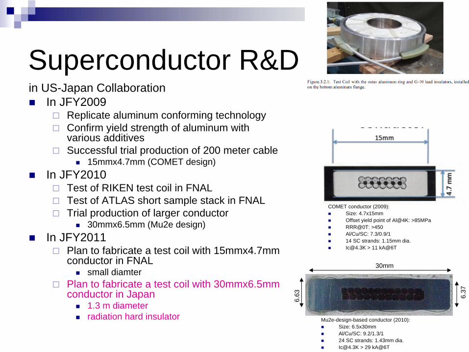
Superconductor R&Din US-Japan Collaboration
In JFY2009Replicate aluminum conforming technologyConfirm yield strength of aluminum with various additivesSuccessful trial production of 200 meter cable
15mmx4.7mm (COMET design)In JFY2010
Test of RIKEN test coil in FNALTest of ATLAS short sample stack in FNALTrial production of larger conductor
30mmx6.5mm (Mu2e design)In JFY2011
Plan to fabricate a test coil with 15mmx4.7mm conductor in FNAL
small diamterPlan to fabricate a test coil with 30mmx6.5mm conductor in Japan
1.3 m diameterradiation hard insulator
COMET conductor (2009):Size: 4.7x15mmOffset yield point of Al@4K: >85MPaRRR@0T: >450Al/Cu/SC: 7.3/0.9/114 SC strands: 1.15mm [email protected] > 11 kA@6T
Mu2e-design-based conductor (2010):Size: 6.5x30mmAl/Cu/SC: 9.2/1.3/124 SC strands: 1.43mm [email protected] > 29 kA@6T
30mm
6.37
6.63

Bending Tests of a Wide Conductor (ATLAS cable)
No problem was found in R=650No problem was found in R=650
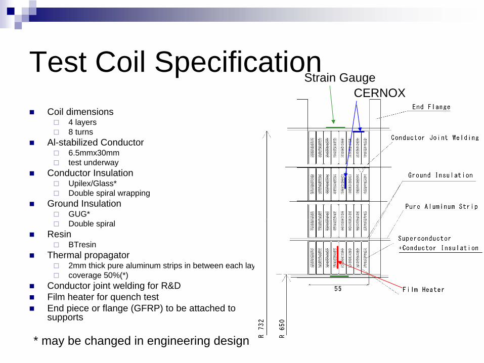
Test Coil SpecificationCoil dimensions
4 layers8 turns
Al-stabilized Conductor6.5mmx30mmtest underway
Conductor InsulationUpilex/Glass*Double spiral wrapping
Ground InsulationGUG*Double spiral
ResinBTresin
Thermal propagator2mm thick pure aluminum strips in between each layercoverage 50%(*)
Conductor joint welding for R&DFilm heater for quench testEnd piece or flange (GFRP) to be attached to supports
* may be changed in engineering design
Strain GaugeCERNOX
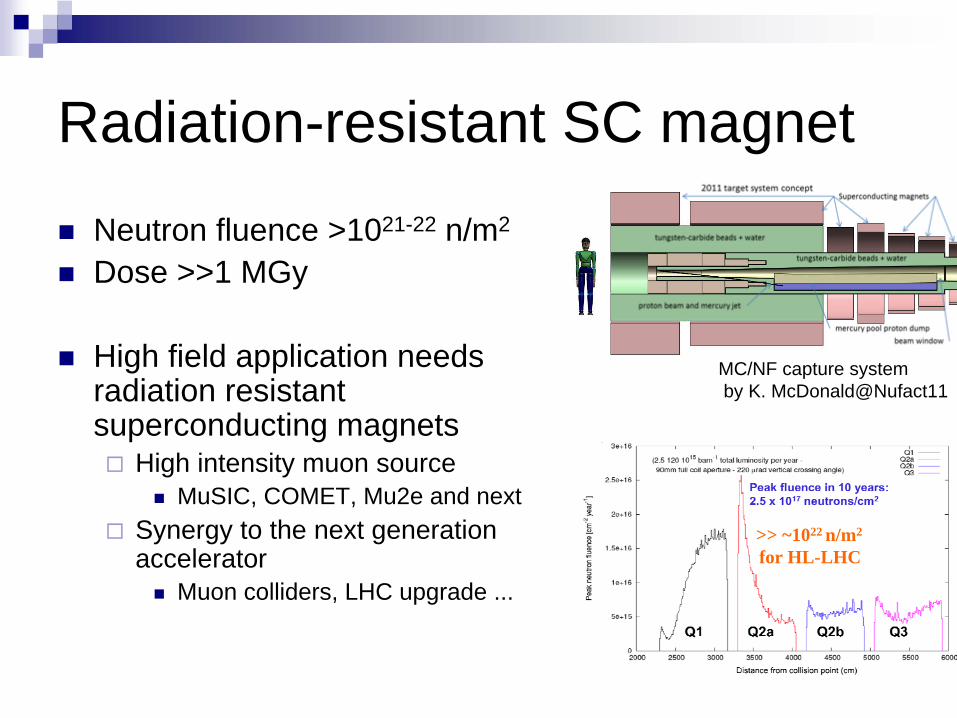
Radiation-resistant SC magnet
Neutron fluence >1021-22 n/m2
Dose >>1 MGy
High field application needs radiation resistant superconducting magnets
High intensity muon sourceMuSIC, COMET, Mu2e and next
Synergy to the next generation accelerator
Muon colliders, LHC upgrade ...
MC/NF capture systemby K. McDonald@Nufact11
>> ~1022 n/m2
for HL-LHC

Radiation hardness of magnet materials
Insulator, resinBT resin, Cyanate esterPolyimide/Glass composite
Thermal insulatorAl-coated polyimide film Less outgas
Support structureGFRP, Titanium rod
SuperconductorNbTi, Nb3Sn would be OK up to 1022 n/m2
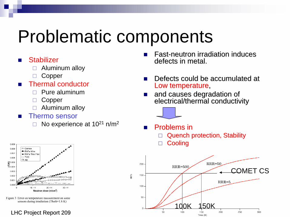
Problematic componentsStabilizer
Aluminum alloyCopper
Thermal conductorPure aluminumCopperAluminum alloy
Thermo sensorNo experience at 1021 n/m2
FastFast--neutron irradiation induces neutron irradiation induces defects in metal.defects in metal.
Defects could be accumulated at Defects could be accumulated at Low temperatureLow temperature,,and causes degradation of and causes degradation of electrical/thermal conductivityelectrical/thermal conductivity
Problems inProblems inQuench protection, StabilityQuench protection, StabilityCoolingCooling
100K 150K
COMET CS
LHC Project Report 209LHC Project Report 209
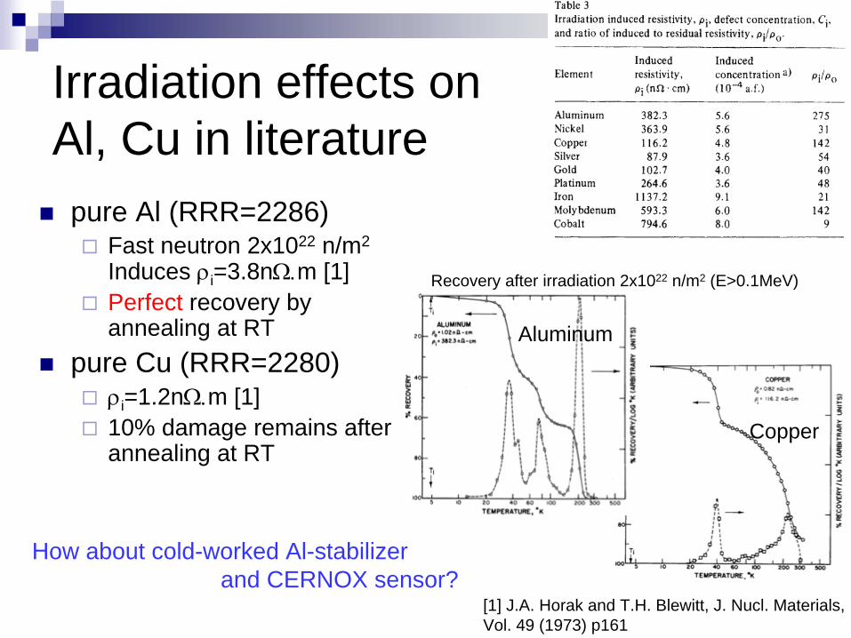
Irradiation effects on Al, Cu in literature
pure Al (RRR=2286)Fast neutron 2x10²² n/m2
Induces ρi=3.8nΩ.m [1]Perfect recovery by annealing at RT
pure Cu (RRR=2280)ρi=1.2nΩ.m [1]10% damage remains after annealing at RT
Recovery after irradiation 2x10²² n/m2 (E>0.1MeV)
Aluminum
[1] J.A. Horak and T.H. Blewitt, J. Nucl. Materials, Vol. 49 (1973) p161
Copper
How about cold-worked Al-stabilizerand CERNOX sensor?
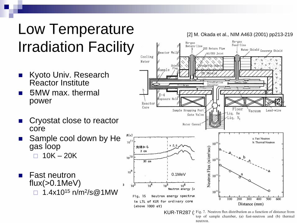
Low Temperature Irradiation Facility
Kyoto Univ. Research Reactor Institute5MW max. thermal power
Cryostat close to reactor coreSample cool down by He gas loop
10K – 20K
Fast neutron flux(>0.1MeV)
1.4x10¹⁵ n/m2/s@1MW
[2] M. Okada et al., NIM A463 (2001) pp213-219
KUR-TR287 (1987)
0.1MeV
[2]

reactorreactor
CryogenicsCryogenics

Irradiation sampleAluminum stabilizer sample from the superconductor by wire electrical discharge machining in KEK
Keep defects by cold-workSize: 1mmx1mmx70mmVoltage taps with 45mm spacing4 wire resistance measurement by nano-voltmeterCERNOX CX-1050-SD close to sample temperature (also irradiated)
Wire EDM
Irradiation sample• 5N aluminum + Cu, Mg
with 10 % cold work• RRR=450
•1.35mΩ @RT, 3μΩ @10K
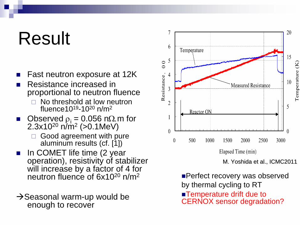
Result
Fast neutron exposure at 12KResistance increased in proportional to neutron fluence
No threshold at low neutron fluence1019-1020 n/m2
Observed ρi = 0.056 nΩ.m for 2.3x10²⁰ n/m2 (>0.1MeV)
Good agreement with pure aluminum results (cf. [1])
In COMET life time (2 year operation), resistivity of stabilizer will increase by a factor of 4 for neutron fluence of 6x10²⁰ n/m2
Seasonal warm-up would be enough to recover
M. Yoshida et al., ICMC2011M. Yoshida et al., ICMC2011
Perfect recovery was observed by thermal cycling to RT
Temperature drift due to CERNOX sensor degradation?

Design StudySo far
Coil layout for field optimizationConceptual design of cryostatEstimation of cryogenics
To doInterface to contents;
Proton target, Beam monitor, Collimator, Stopping target, DetectorsRemote handling, installation/disassembly procedureCoil structure test winding (conductor R&D)Cryogenics design
Optimize refrigeratorLHe pipingThermal linksThermal cycling procedure
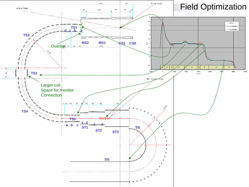
Coil LayoutCS0CS1MS1MS2
TS1abcd
TS2
TS3
TS4
TS5a b c
Overlap
Larger coilSpace for monitorConnection
ST11 2
ST2
1 2
ST3SS
DS
Field Optimization
COMETMagnetDesign target
station
experimentalhall
proton beam
Concrete
CryostatCryostat--11
CryostatCryostat--22
CryostatCryostat--33
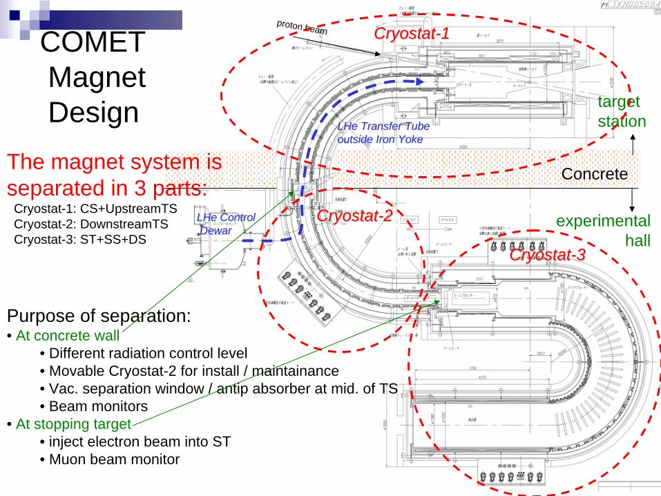
The magnet system is separated in 3 parts:
Cryostat-1: CS+UpstreamTSCryostat-2: DownstreamTSCryostat-3: ST+SS+DS
Purpose of separation:• At concrete wall
• Different radiation control level• Movable Cryostat-2 for install / maintainance• Vac. separation window / antip absorber at mid. of TS• Beam monitors
• At stopping target• inject electron beam into ST• Muon beam monitor
LHeLHe ControlControlDewarDewar
LHeLHe Transfer TubeTransfer Tubeoutside Iron Yokeoutside Iron Yoke
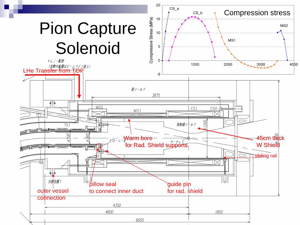
Pion Capture Solenoid
LHe Transfer from TOP
sliding rail
pillow sealto connect inner duct
guide pinfor rad. shieldouter vessel
connection
Warm boreWarm borefor Rad. Shield supportsfor Rad. Shield supports
45cm thick45cm thickW ShieldW Shield
Compression stress
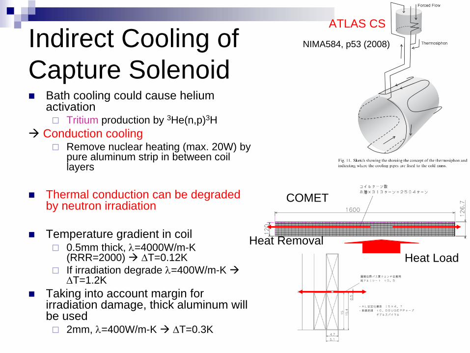
Indirect Cooling of Capture Solenoid
Bath cooling could cause helium activation
Tritium production by 3He(n,p)3HConduction cooling
Remove nuclear heating (max. 20W) by pure aluminum strip in between coil layers
Thermal conduction can be degraded by neutron irradiation
Temperature gradient in coil0.5mm thick, λ=4000W/m-K (RRR=2000) ΔT=0.12KIf irradiation degrade λ=400W/m-K ΔT=1.2K
Taking into account margin for irradiation damage, thick aluminum will be used
2mm, λ=400W/m-K ΔT=0.3K
COMET
ATLAS CS
NIMA584, p53 (2008)
Heat LoadHeat Removal

Design StudySo far
Coil layout for field optimizationConceptual design of cryostatEstimation of cryogenics
200W refrigerator for upstream magnets30W GM cryocoolers for downstream magnets
To doInterface to contents;
Proton target, Beam monitor, Collimator, Stopping target, DetectorsRemote handling, installation/disassembly procedureCoil structure test winding (conductor R&D)Cryogenics design
Optimize refrigeratorLHe pipingThermal linksThermal cycling procedure

Summary and ProspectsSolenoid capture scheme is adapted for high intensity muon source in NF/MC, mu-e conversion experiments
Radiation issues are most important for the feasibilityIrradiation effects on electrical and thermal propertiesIndirect coolingRadiation hard organic materials
Steady R&D on irradiation effects is underwayFirst test successfully done in 2010Degradation of electric resistivity of Al-CuMg was observed from ~1020 n/m2.Full recovery by thermal cycle to room temperature was also confirmed.Will investigate different additives, copper, pure aluminum for thermal conduction.
Feasibility of proposed coil structure will be checked in the test coil using large Al-stabilized superconductor.
Detailed design will take into account the R&D results.