Embed Size (px)
Citation preview

© A
rc E
uro
Trad
e Lt
d, E
ngla
nd 2
011
© A
rc E
uro
Trad
e Lt
d, E
ngla
nd 2
011
- 1 -
A picture story book to help you dismantle and reassemble your Sieg Super X3 Mill
Arc Euro Trade Ltd.10 Archdale Street, Syston, Leicester, LE7 1NA.Web: www.arceurotrade.co.uk Phone: 0116 269 5693.
Super X3 Mill
Dismantling and Reassembly Guide

© A
rc E
uro
Trad
e Lt
d, E
ngla
nd 2
011
- 2 -
The SIEG Super X3 Mill is currently one of the most popular small mills available to model engineers today. SIEG Super X3 Mill VersionsSuper X3 (the machine detailed in this guide): This mill is of cast iron construction and has a rigid dovetail column and a head which may be tilted up to 90° each way. The spindle may have either an R8 or MT3 taper and is driven directly by a powerful brushless 1000W DC motor via a toothed timing belt. The motor is electronically controlled to give a fully variable speed range up to 1750 rpm. In contrast to the SIEG X3 Small Mill, the Super X3 range is not fi tted with a geared head to increase torque at low speeds since the combination of electronics and brushless motor are powerful enough without gears. Consequently, the Super X3 mill is a quieter machine.Super X3L The “L” stands for “Extra Long Table” and with an
effective table size of 625x204mm its probably the largest table for this class of mill. The SIEG Super X3 and Super X3L Mills are available in both metric and imperial versions. This picture story guide is designed to help you dismantle, reassemble, lubricate and make the proper adjustments to your Mill. Before dismantling your Super X3 Mill, you should read through the entire guide and assess that you have the required equipment and skills to complete the task. Although not expressly stated at each stage in this guide, every part is thoroughly cleaned in a paraffi n type degreaser before reassembly. For lubrication, we recommend Molyslip HSB grease (ARC code: 170-100-10300), and a good quality lubricating oil such as Rock Oil HLP 32 Hydraulic Oil (ARC code: 170-150-00400). We do not recommend using automotive engine oil or 3-in-1 oil.
1. The mill out of the box and we are ready to start work.
2. Remove the chuck guard.3. Undo the drawbar and remove the drill
chuck.
© A
c E
uT
ro T
L, E
ng20
d 20
11©
Ar
Arc
Eu
c E
uro
Tro
Tra
dera
deLt
dLt
d, E
n, E
ngla
ngl
and
20d
2011
- 2 -
4. Remove the 6 screws securing the spindle speed display housing and pull away. 5. Unplug the speed display from the harness.
6. Undo 4 Allen bolts.
7. Lift off the top housing.
PLEASE READ THIS FIRST

© A
rc E
uro
Trad
e Lt
d, E
ngla
nd 2
011
- 3 -
16. Undo 4 screws from DRO and remove from head. 17. Undo 2 screws from spindle sleeve location dowel and remove.
18. Remove the fi ne feed locking knob. 19. Remove circlip. 20. Remove handwheel assembly.
© A
c E
uT
ro T
L, E
ng20
d 20
11©
Ar
Arc
Eu
c E
uro
Tro
Tra
dera
deLt
dLt
d, E
n, E
ngla
ngl
and
20d
2011
- 3 -
21. Undo 2 screws under handwheel housing & disconnect contact strip. 22. Undo 4 screws and remove wiring cover under head.
8. Remove the spindle locking bolt. 9. Unscrew the DRO Bracket from the spindle sleeve.
10. Slacken the locknut attaching the DRO bar to the bracket.
11. Pull down DRO bar level with spindle - DO NOT pull out.
12. Remove the 4 screws securing the front cover assembly.
13. Lift the cover away from the head.
14. Disconnect all plugs and wiring. 15. De-solder the power LED and remove cover.

© A
rc E
uro
Trad
e Lt
d, E
ngla
nd 2
011
- 4 -
© A
c E
uT
ro T
L, E
ng20
d 20
11©
Ar
Arc
Eu
c E
uro
Tro
Tra
dera
deLt
dLt
d, E
n, E
ngla
ngl
and
20d
2011
- 4 -
29. Remove motor plate fi xing screws. 30. Remove drive belt.
31. Undo 4 cap head screws and lift out the belt pulley housing.
24. Carefully unlatch the spindle return spring housing and remove.23. Undo the 4 screws securing the fi ne feed housing and lift housing away from the head.
27. Remove 3 cap head screws from the fl ange and pull out the handwheel shaft. 28. The spindle, fi ne feed housing and handwheel shaft.
25. Remove the handwheel shaft retaining circlip.
26. Support the spindle assembly and pull the handwheel shaft out to disengage the quill. Drop the spindle assembly down and out.

© A
rc E
uro
Trad
e Lt
d, E
ngla
nd 2
011
- 5 -
33. Disconnect motor wires from speed control board. 34. Pull motor signal wire plug.
35. Disconnect wires from plug. 36. Unwrap motor supply wires and motor signal wires from the ferrite cores.
© A
c E
uT
ro T
L, E
ng20
d 20
11©
Ar
Arc
Eu
c E
uro
Tro
Tra
dera
deLt
dLt
d, E
n, E
ngla
ngl
and
20d
2011
- 5 -
37. Disconnect motor earth wires. 38. Undo gland nut from motor lead tube and pull out motor wires. 39. Undo gland nut at head end.
40. Pull lead tube from wires. 41. Remove gland from head. 42. Lift out motor feeding wires through head.
43. Undo and remove lower gland from head. 44. Pull out wiring. 45. Remove rear panel assembly.
32. Remove rear panel covers.
- 6 -- 6 -
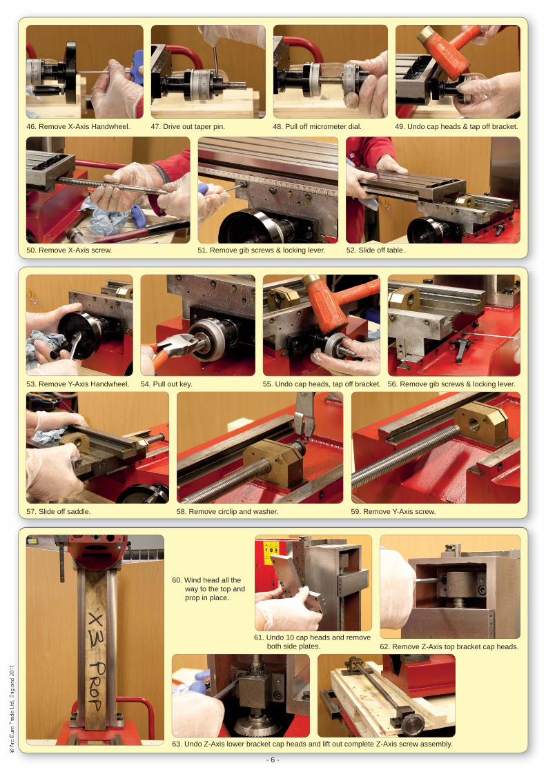
46. Remove X-Axis Handwheel. 47. Drive out taper pin. 48. Pull off micrometer dial. 49. Undo cap heads & tap off bracket.
50. Remove X-Axis screw. 51. Remove gib screws & locking lever. 52. Slide off table.
53. Remove Y-Axis Handwheel. 54. Pull out key. 55. Undo cap heads, tap off bracket. 56. Remove gib screws & locking lever.
57. Slide off saddle. 58. Remove circlip and washer. 59. Remove Y-Axis screw.
60. Wind head all the way to the top and prop in place.
61. Undo 10 cap heads and remove both side plates. 62. Remove Z-Axis top bracket cap heads.
63. Undo Z-Axis lower bracket cap heads and lift out complete Z-Axis screw assembly.

© A
rc E
uro
Trad
e Lt
d, E
ngla
nd 2
011
- 7 -
© A
c E
uT
ro T
L, E
ng20
d 20
11©
Ar
Arc
Eu
c E
uro
Tro
Tra
dera
deLt
dLt
d, E
n, E
ngla
ngl
and
20d
2011
- 7 -
75. Support the weight of head assembly. 76. Remove 2 nuts and washers securing head. 77. Pull head away from carrier bracket.
64. Undo 2 grub screws and remove gear. 65. Lift out key. 66. Drift out taper pin.
67. Remove bearing block assembly. 68. Unscrew leadscrew from nut pulling off the top bracket at the same time.
69. Undo 2 grub screws and remove gear. 70. Remove Z-Axis handwheel. 71. Lift out key.
72. Remove 3 screws & pull off bearing assembly. 73. Lift out key. 74. Pull out Z-Axis handwheel shaft.

- 8 -
78. Head carrier bracket / vertical slide.
79. Rear view of head showing bushed 0° and 90° locating holes.
80. Remove T-bolts. 81. Pull off sprung pressure pad & springs.
82. Showing head location pin in the engaged and disengaged positions.
- 8 -
83. Slacken off the gib adjusting screw. 84. Lift off head carrier bracket / vertical slide assembly.
85. Dismantle the carrier bracket mechanism. 86. Showing the gib strip, adjusting screw and locking screw and locking lever brass dowel.

© A
rc E
uro
Trad
e Lt
d, E
ngla
nd 2
011
- 9 -
© A
c E
uT
ro T
L, E
ng20
d 20
11©
Ar
Arc
Eu
c E
uro
Tro
Tra
dera
deLt
dLt
d, E
n, E
ngla
ngl
and
20d
2011
- 9 -
87. Grease and fi t shaft into vertical slide. 88. Fit location screw, pinch and back off 1 turn. 89. Grease and fi t head location shaft.
90. Engage splines & wind-in using Allen key. 91. Fit spring in back of shaft. 92. Fit retaining plate.
93. Fit head rotation spigot. 94. Lock retaining plate screws. 95. Grease and fi t the gib adjusting and locking screws.
96. Locate gib strip slot on adjusting screw and oil dovetails. 97. Slide onto column, rest on prop and tighten gib strip.
98. Offer head up and locate T-bolts through head.97. Fit plastic pressure disc with
springs & fi t T-bolts in T-slot.99. Fit nuts & washers to T-bolts, pinch
up then back off 1/2 turn.
100. Using Allen key, disengage location shaft by turning clockwise, then spin head. 101. Check head locks at 90°. 102. Return head to 0° and lock down nuts.

© A
rc E
uro
Trad
e Lt
d, E
ngla
nd 2
011
- 10 -
103. Grease & fi t Z-axis handwheel shaft. 104. Fit inner thrust bearing assembly. 105. Fit bearing fl ange and outer thrust bearing.
106. Fit key and handwheel assembly and adjust to remove backlash. 107. Fit rear gear but leave loose.
108. Grease & fi t nut to leadscrew. 109. Press top bearing bracket onto Z-axis leadscrew.
111. Fit lower thrust bearing. 112. Fit collar & tap in taper pin. 113. Fit key and gear, don’t tighten.
© A
c E
uT
ro T
L, E
ng20
d 20
11©
Ar
Arc
Eu
c E
uro
Tro
Tra
dera
deLt
dLt
d, E
n, E
ngla
ngl
and
20d
2011
- 10 -
110. Fit locknuts & washer. Grease & fi t upper thrust bearing & block.
114. Adjust backlash out of bearing block and lock up.
115. Fit Z-axis screw assembly. Tap in taper pins & tighten bolts.
116. Adjust mesh on gears, lock screws and grease.
117. Fit side plates and loosely fi t screws. 118. Tighten gib to lock head.
119. Tap taper pins home. 120. Lock side plate cap head screws.121. Slacken off gib screws. Wind head up and down and
adjust gib to suit and tighten lock screw.

© A
rc E
uro
Trad
e Lt
d, E
ngla
nd 2
011
- 11 -
© A
c E
uT
ro T
L, E
ng20
d 20
11©
Ar
Arc
Eu
c E
uro
Tro
Tra
dera
deLt
dLt
d, E
n, E
ngla
ngl
and
20d
2011
- 11 -
128. Spindle components laid out. 129. Fit inner grease shield.
123. Press spindle out of sleeve. 124. The spindle and sleeve separated.
125. Use a bearing puller to remove the top bearing. 126. Press out the nose bearing & grease shields.
127. Suggested Modifi cation: Reduce the diameter of the spindle fl ange to assist with any future dismantling.
Spindle RefurbishmentDismantling of a Super X3 Spindle for refurbishment can be a diffi cult process and for this reason we offer a refurbishment service.
During the dismantling process, there is a high probability that the taper roller bearing 32907J2 will be damaged. This is due to the spindle assembly design. It is therefore recommended that this bearing be changed when carrying out any refurbishment of the Super X3 Spindle assembly, along with thrust ball bearing 51106, which could also be effected.
The ARC refurbishment process includes dismantling, cleaning, greasing with Molyslip HSB, and a small modifi cation is made to the fl ange of the spindle to assist with future dismantling. It is then re-assembled, test run and adjustments made. Please check our website for further details - order code: 080-030-01704.
If you are confi dent that you have the required tools and skills to refurbish the spindle assembly, the following steps outline what’s involved.
122. Undo and remove lock nuts & washer from spindle assembly.

© A
rc E
uro
Trad
e Lt
d, E
ngla
nd 2
011
- 12 -
130. Fit and press in taper roller bearing outer race. 131. Grease and fi t bearing. 132. Fit outer grease shield.
133. Press in spindle. 134. Grease and fi t lower thrust washer, bearing and top thrust washer.
135. Fit spacer. 136. Fit and press in top bearing.
137. Fit washer. 138. Fit lock nuts. Adjust and lock nut to preload. 139. Check free movement of spindle.
© A
c E
uT
ro T
L, E
ng20
d 20
11©
Ar
© A
rc E
uc
Eur
o T
ro T
rade
rade
Ltd
Ltd,
En
, Eng
lan
glan
d 20
d 20
11
- 12 -
141. Remove circlip. 142. Slide off washer and gear. 143. Push out 2 steel balls.
144. Push in plunger. 145. Push out 3rd ball. 146. Tap out plunger. 147. Remove circlip.
140. Remove key and lever off insulated bush assembly.

© A
rc E
uro
Trad
e Lt
d, E
ngla
nd 2
011
- 13 -
148. Slide off mounting fl ange.
© A
c E
uT
ro T
L, E
ng20
d 20
11©
Ar
Arc
Eu
c E
uro
Tro
Tra
dera
deLt
dLt
d, E
n, E
ngla
ngl
and
20d
2011
- 13 -
149. Component parts of the handwheel shaft.
150. Re-assembly is the reverse of above.
150. Assemble, grease and fi t the spindle lock.151. Lightly oil bottom of spindle bore,
slide in spindle assembly and lock. 152. Grease and fi t handwheel shaft assembly.
153. Temporarily fi t the handwheel and wind up and down to check for free movement.
154. Grease and fi t the spindle sleeve guide peg. 155. Fit the top pulley bearing housing.
156. Lock down handwheel shaft fl ange. 157. Position handwheel to your preference. 158. Fit retaining circlip.
159. Fit the spindle spring return unit. 160. Check that spindle returns.

© A
rc E
uro
Trad
e Lt
d, E
ngla
nd 2
011
- 14 -
© A
c E
uT
ro T
L, E
ng20
d 20
11©
Ar
Arc
Eu
c E
uro
Tro
Tra
dera
deLt
dLt
d, E
n, E
ngla
ngl
and
20d
2011
- 14 -
172. Fit key, handwheel, spacer & circlip. 173. Fit locking knob. 174. Fit brass plunger and locking lever.
161. Fine Feed Housing. 162. Remove Handwheel. 163. Remove end cap.
164. Remove the worm shaft. 165. The worm shaft assembly. 166. Grease and reassemble the fi ne feed unit.
167. Fit rear electronics panel and feed cables through to front of head.
169. Fit fi ne feed housing to head. 170. Attach wire to wiper contact. 171. Fit unit into base of housing.
168. Feed cable through fi ne feed housing.

© A
rc E
uro
Trad
e Lt
d, E
ngla
nd 2
011
- 15 -
178. Tape up end of motor wires. 179. Feed wires through lead tube. 180. Fit lead tube to gland. 181. Feed wires through side of panel.
182. Fit lead tube to gland and feed wires to exit lower opening. 183. Wrap signal wires through ferrite core and connect to terminal block.
184. Wrap motor wires through ferrite core & connect to terminal block. 185. Connect earth wire. 186. The fi nished panels.
© A
c E
uT
ro T
L, E
ng20
d 20
11©
Ar
Arc
Eu
c E
uro
Tro
Tra
dera
deLt
dLt
d, E
n, E
ngla
ngl
and
20d
2011
- 15 -
187. Temporarily remove the spindle sleeve lock. 188. Fit DRO (do not attach to spindle yet). 189. Reconnect wires to the front control panel.
175. Feed motor cables through top of head & out through the side.
176. Lower motor into head whilst pulling cables out of side.
177. Fit gland to head.

© A
rc E
uro
Trad
e Lt
d, E
ngla
nd 2
011
- 16 -
© A
c E
uT
ro T
L, E
ng20
d 20
11©
Ar
Arc
Eu
c E
uro
Tro
Tra
dera
deLt
dLt
d, E
n, E
ngla
ngl
and
20d
2011
- 16 -
205. Lightly fi t gib screws. 206. Grease and fi t inner thrust race.
195. Fit belt & adjust tension. 196. Replace top cover. 197. Reconnect speed display and fi x to head.
198. Attach lower motor cover. 199. Fit rear covers. 200. The spindle is now ready to run.
190. Push DRO bar down. 191. Fit control panel (checking no wires are trapped) and fi x in place. 192. Re-fi t the spindle sleeve lock.
193. Attach the DRO bracket to the spindle sleeve and pinch the lock nuts up. 194. Work spindle up & down to check DRO operation.
201. Grease/oil Y-axis screw and nut and assemble. Fit washer and circlip. 202. Oil bed and saddle dovetails and assemble. 203. Slide in gib strip.
204. Modify gib screws to a cone point

© A
rc E
uro
Trad
e Lt
d, E
ngla
nd 2
011
- 17 -
© A
c E
uT
ro T
L, E
ng20
d 20
11©
Ar
Arc
Eu
c E
uro
Tro
Tra
dera
deLt
dLt
d, E
n, E
ngla
ngl
and
20d
2011
- 17 -
213. Slide gib into place. 214. Loosely fi t gib screws.
215. Grease/oil the X-axis screw & fi t. 216. Grease & fi t inner thrust bearing. 217. Grease & fi t screw bracket. 218. Grease & fi t outer thrust bearing.
220. Fit handwheel assembly. 221. Final adjust gib screws for free movement/no slop in table. Pinch up lock nuts.
222. Wind table to one end & place thumb over the joint between saddle and base. Push & pull on table to check slop. Repeat this on joint between saddle and table. Adjust gibs if necessary to minimise any slop.
207. Grease & fi t screw bracket. 208. Grease & fi t outer thrust bearing.
210. Final adjust gib screws for free movement/no slop in ways. Pinch up lock nuts. 211. If necessary, adjust Y-axis backlash from rear of saddle.
209. Fit key & handwheel assembly and adjust backlash.
212. Oil table & saddle dovetails and slide the table onto the saddle.
219. Fit micrometer hub and attach with taper pin.
223. Fit the locking levers.

© A
rc E
uro
Trad
e Lt
d, E
ngla
nd 2
011
- 18 -
© A
c E
uT
ro T
L, E
ng20
d 20
11©
Ar
Arc
Eu
c E
uro
Tro
Tra
dera
deLt
dLt
d, E
n, E
ngla
ngl
and
20d
2011
- 18 -
The fi nished Super X3 Mill.