Embed Size (px)
Citation preview

Super Fast Camera System
Performed by:Tokman Niv
Levenbroun Guy
Supervised by:Leonid Boudniak

The concept: combine multiple “off the shelf” cameras, to create a sequence of frames to capture a fast moving object.
An FPGA will be used to coordinate and synchronize the cameras.
The image data will be read into a computer, where it will be processed.
Project Overview

Choose an appropriate image sensor, to fit our goals.• We found two appropriate sensors. • In order to use the sensors, a creation of a
complex PCB (printed circuit board) is required.
• To carry on with the rest of the project, a camera module was found as well, that doesn’t fit the project definitions, but close enough.
Project Goals

Camera Module
• PhotonFocusModelOEM-D640C-66
Shutter time40us-1.3ms
On-chip featuresAmplifiers, ADC
Output typeDigital,
8 bit/pixel
Resolution640x480
Remarks:• No Readout control is possible !

Design a controller to operate a single and two sensors.
• In the presentation we will focus on this subject.
Project Goals
Most image sensors/Camera modules operate at 33MHz~66MHz Pixel rate
Without a specific camera, we’ll assume a 33 MHz pixel rate from the camera, 8 bit per pixel => 33 Mbyte/sec
In case of N cameras sending data in parallel, effective input data rate to the system is 33*N Mbyte/sec. N=2 => 66 Mbyte/sec
System Data Rates

Use a NallaTech board• PCI interface allows direct connection to PC.• No onboard memory.• Allows user external circuit connection
Drawbacks:• No memory onboard requires real-time data transfer
from the cameras via the PCI to the PC. • PCI peak rate is 132 Mbyte/sec. But when
considering bus load and protocol timing, 66Mbyte/sec becomes problematic.
• Design is limited to 2 cameras max.
Implementation Possibilities

Implementation Possibilities Use the memec design virtex2 pro™ board
• The p160 expansion card enable us to connect multiple cameras.
• On board memory (32 MByte sdram).• PC connection via USB or RS-232• Offers more flexibility through embedded
CPU.
Drawbacks:• Limited accessibility to the board.

Implementation Possibilities Conclusion:
• NallaTech’s board offers limited design options and low bandwidth. Extensions to the design to support more than a few cameras is not possible.
• We chose the Memec Design development board as our implementation environment.

Implementation approach
No simple SDRAM controller core is available. Implementing one is complex and time consuming.
There is an SDRAM controller with PLB/OPB bus interface, allowing us to use it but requires that our system will also have a bus interface.
Using PPC to access the memory has high overhead, hence lower bandwidth.
By using the DMA option of the bus interface, data flows at maximum speed.

Implementation approach
SDRAM data width is 32 bit. From each camera, we’ll pack 3 pixels (3
bytes), and the forth will contain camera number and packet number.
32 bit bus data rate:
100 4 75% (50% 80%) 120
sec
bus efficiencydata efficiencybyte MByte
MHzcycle

SDRAM
Computer
FIFOCAMERA 1
CAMERA 2
MAIN CONTROLLER
System Block Diagram
1 - integration 2 – data storage 3 – data readout

Stage 1 - Integration
INTEGRATION AND
READOUT TIMER /
CONTROLLER
CAMERA INTERFACE
CAMERA INTERFACE
The Controller signals each camera in turn to start integration, using the camera interface.
Each camera interface is responsible for generating appropriate signals and timing
Stage 2 – Read Out
PLB
SDRAM
DMA
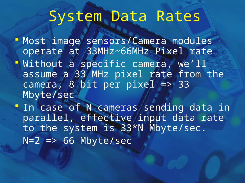
Each camera send data to a dedicated FIFO. An arbiter selects each camera in turn to send a
packet of 3 bytes + 1 byte header to the main FIFO.
Using the PLB bus interface and DMA options, the main FIFO sends the packets to
the SDRAM.

Stage 3 – Data Transfer
PLB
SDRAM
PPC
PLB – OPB BRIDGE
OPB
UARTComputer
RS232
After the images are stored in memory, the data is read from the SDRAM and sent to the PC via RS-232 (or USB).
We consider using the PPC for
that task.

System Block Diagram

Milestones We need a board to work on. Design a simple test bench to test and
understand DMA operation. Design and implement a FIFO with DMA
capabilities, and test it against a stream of data at 66 Mbyte/sec.
Complete the Integration and Readout Timer/controller.
Enable sdram readout to PC through RS-232 (or USB). Consider using PPC.