Embed Size (px)
Citation preview

1
FORD F450 & 550 SUPER DUTY CHASSIS CABS 4X2 & 4X4
2005-NEWER MODELS Link Part No. 8M000097
(Capacity 13,660 lbs) Rear Axle
80002162 FEB 11, 2015
INS
TA
LL
AT
ION
GU
IDE
Ques-
tions ? Contact this Professional Installer :
Company : _________________________________________
_________________________________________
Phone : _________________________________________

2
INSTALLATION INSTRUCTIONS INDEX 1.0 INTRODUCTION . . . . . . . . . . . . . . . . . . . . . . . . . . . . . . . . . . . pg. 3 2.0 OE SHOCK AND ROLL BAR REMOVAL. . . . . . . . . . . . . . . . . pg. 5 3.0 DRIVER SIDE DISASSEMBLY. . . . . . . . . . . . . . . . . . . . . . . . . pg. 6 4.0 DRIVER SIDE ASSEMBLY. . . . . . . . . . . . . . . . . . . . . . . . . . . . pg. 7 5.0 PASSENGER SIDE DISASSEMBLY . . . . . . . . . . . . . . . . . . . . pg. 9 6.0 PASSENGER SIDE ASSEMBLY . . . . . . . . . . . . . . . . . . . . . . . pg. 9 7.0 CROSSMEMBER, LATERAL CONTROL ROD, & STABILIZER BAR . . . . . . . . . . . . . . . . . . . . . . . . . . . . . . . pg. 11 8. E-BRAKE LINE ROUTING, AND SHOCK RE-INSTALLATION. . .pg. 14 9.0 AIR CONTROL SYSTEM & ELECTRICAL. . . . . . . . . . . . . . . .pg. 18 10.0 AXLE ALIGNMENT. . . . . . . . . . . . . . . . . . . . . . . . . . . . . . . . . .pg. 19
INSPECTION AND SERVICE INSTRUCTIONS INDEX 11.0 FINAL INSPECTION CHECKLIST. . . . . . . . . . . . . . . . . . . . . . pg. 20 12.0 OPERATION GUIDELINES. . . . . . . . . . . . . . . . . . . . . . . . . . . pg. 21 13.0 SERVICE & MAINTENANCE . . . . . . . . . . . . . . . . . . . . . . . . . pg. 23 MISCELLANEOUS INFORMATION TORQUE TABLE. . . . . . . . . . . . . . . . . . . . . . . . . . . . . . . . . . . pg. 22 PARTS LIST. . . . . . . . . . . . . . . . . . . . . . . . . . . . . . . . . . . . . . . pg. 24 DRIVELINE INFORMATION . . . . . . . . . . . . . . . . . . . . . . . . . . pg. 26

3
WARNING! Proper tightening of U-Bolt nuts
and mounting nuts are required for proper operation. Need for proper Torque value is indicated by wrench symbol and values will be found in Table 12-1 in Maintenance section of the instructions. Failure to maintain proper torque can cause component failure resulting in accident with consequent injury.
1. INTRODUCTION IMPORTANT! It is important that the entire installation instructions be read thoroughly before proceeding with suspension installation.
PRODUCT INSTALLER RESPONSIBILITIES
Installer is responsible for installing the product in accordance with Link Mfg. specifications and installation instructions.
Installer is responsible for providing proper vehicle components and attachments as well as required or necessary clearance for suspension components, axles, wheels, tires, and other vehicle components to ensure a safe and sound installation and operation.
Installer is responsible for advising the owner of proper use, service and maintenance required by the product and for supplying maintenance and other instruction as readily available from Link Mfg..
SAFETY SYMBOLS, TORQUE SYMBOL, and NOTES
WARNING! A correct installation must result in the suspension and axle being
“loaded” within the range specified by axle and suspension manufacturers. Please check vehicle specifications and intended usage to insure axle will be within Gross
Axle Weight Rating (GAWR). No alteration of any suspension component is permitted. Link Mfg. Is not responsible for damages from improper installation or operations beyond design capability. Link Mfg. In its sole discretion shall determine whether or not any product is defective or otherwise covered by warranty.
This is the safety alert symbol. It is used to alert you to potential personal injury hazards. Obey all safety messages that fol-low this symbol to avoid possible injury or death.
WARNING
WARNING indicates a po-tentially hazardous situa-tion which, if not avoided, could result in death or serious injury.
CAUTION
CAUTION indicates a po-tentially hazardous situa-tion which, if not avoided, could result in minor or moderate injury.
CAUTION
CAUTION used without the safety alert symbol indi-cates a potentially hazard-ous situation which, if not avoided, may result in property damage.
The torque symbol alerts you to tighten fasteners to a spec-ified torque value.
NOTE:
A Note provides information or suggestions that help you correctly perform a task.
The electrical symbol indi-cates the presence of electric shock hazards which, if not avoided, may result in injury to personnel or damage to equipment.

4
PRE-INSTALLATION CHECKLIST Check the vehicle wheel alignment prior to installation to insure no precondition exists; record
the information for verification.
Measure & record the wheelbase and centering dims before beginning installation.
Remove the attached body, if applicable. Remember to disconnect all electrical connections to the body, and fuel filler tube, before removing the body. The installation can also be completed using a lift to raise the vehicle. If using a lift, chassis body removal may not be necessary but removal of rear wheels will aid in installation.
If not using a lift, block the front wheels and apply the emergency brake so the vehicle cannot roll.
Jack up the rear frame of the truck in order to unload the rear leaf springs (or use an overhead hoist). Do not lift the wheels off the ground (if not using a lift to install the suspension). Do not jack on the axle itself.
Install the suspension in the listed sequence. Install one side of the suspension at a time. First, install the driver side completely, then install the passenger side. Removal of the rear wheels may aid in installation, but it is not necessary.

5
2. OE SHOCK AND ROLL BAR REMOVAL 1. Remove the OEM shock absorbers and retain the mounting fasteners for later use.
2. Remove the OEM stabilizer bar and brackets/linkages from the axle and frame. Retain the bolts from the axle brackets for future use. See Figure 2-1. Reattach the brake cable to the passenger side stabilizer bar bracket location (same location as before removing brackets).
RETAIN THESE BOLTS
DISCARD OEM STABILIZER BAR
FIG. 2-1
DISCARD OEM STABILIZER LINK
DISCARD OEM SHOCKS
DISCARD OEM BRACKET
RETAIN ALL SHOCK BOLTS & NUTS
INTRODUCTION (cont.) INSTALLATION NOTES:
Drilling of new frame holes is required for installation of the suspension.
The Ford F450 UltraRide is shown throughout these installation instructions, there is no difference for the F550. It will follow the same sequence and setup as depicted.
Minimum clearances required for proper suspension operation Between Exhaust and Air Spring: 3 inches (unless heat shield is provided) Between Tire and Air Spring: 1.5 inches. Between Exhaust and any suspension hard point: 1.0 inch
(e.g. Lateral Control Rod) Between Exhaust and Cross-member/LCR Mount: 0.3 inch
6
3. DRIVER SIDE DISASSEMBLY
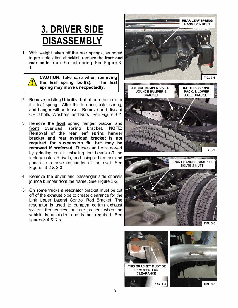
1. With weight taken off the rear springs, as noted in pre-installation checklist, remove the front and rear bolts from the leaf spring. See Figure 3-1.
2. Remove existing U-bolts that attach the axle to the leaf spring. After this is done, axle, spring, and hanger will be loose. Remove and discard OE U-bolts, Washers, and Nuts. See Figure 3-2.
3. Remove the front spring hanger bracket and front overload spring bracket. NOTE: Removal of the rear leaf spring hanger bracket and rear overload bracket is not required for suspension fit, but may be removed if preferred. These can be removed by grinding or air chiseling the heads off the factory-installed rivets, and using a hammer and punch to remove remainder of the rivet. See Figures 3-2 & 3-3.
4. Remove the driver and passenger side chassis jounce bumper from the frame. See Figure 3-2.
5. On some trucks a resonator bracket must be cut off of the exhaust pipe to create clearance for the Link Upper Lateral Control Rod Bracket. The resonator is used to dampen certain exhaust system frequencies that are present when the vehicle is unloaded and is not required. See figures 3-4 & 3-5.
CAUTION: Take care when removing the leaf spring bolt(s). The leaf spring may move unexpectedly.
REAR LEAF SPRING HANGER & BOLT
FIG. 3-1
FRONT HANGER BRACKET, BOLTS & NUTS
FIG. 3-3
JOUNCE BUMPER RIVETS, JOUNCE BUMPER &
BRACKET
U-BOLTS, SPRING PACK, & LOWER AXLE BRACKET
FIG. 3-2
FIG. 3-4 FIG. 3-5
THIS BRACKET MUST BE REMOVED FOR
CLEARANCE

7
4. DRIVER SIDE ASSEMBLY 1. Review Figures 4-1 & 13-2 to acquaint yourself with the various parts of the UltraRide
suspension.
2. If the parking brake cable runs in front of the axle on the passenger side, remove the attachment bolt from the axle/shock bracket. It will be repositioned in Section 8.
3. Important: On 2011 and later trucks, the Brake Line Mounting Bracket must be modified as
shown in Assembly Addendum Included at the end of this manual.
4. Place the OE Axle Seat onto the top of the axle as shown in Fig. 4-1. Place the Upper Axle Bracket onto the top of the axle over the axle seat. Insert (4) 1/2 x 8 UNC BOLTS into the Upper Axle Bracket.
5. DRIVER SIDE ONLY: Fasten the Upper Axle Bracket to the OEM stabilizer bar mount location on the axle using the 10mm OEM fasteners that were retained from Section 2.2. See Figure 4-2. (See Table 12-1 on page 18 for appropriate Torque) Note: Do not over-tighten these bolts to prevent stripping the captive nut.
OEM BOLTS FASTEN UPPER AXLE BRACKET ON DRIVER SIDE ONLY
FIG. 4-2
FIG. 4-1

8
5. Fasten the Lower Axle Bracket to the Upper Axle Bracket using (4) 1/2 UNC TOP LOCK NUTS. (See Table 12-1 page for appropriate Torque) Note: if contacting the brake lines, slightly bend the brake line bracket down and towards the axle to make clearance at least 1/4” between the brake line and the axle brackets.
6. Fasten the Frame Hanger to the frame using (4) 5/8 x 1 1/2 UNC FLANGE BOLTS, (4) 5/8 UNC TOP LOCK NUTS, (2) 9/16 x 1 3/4 UNF HEX CAP SCREWS, (2) 9/16 UNF TOP LOCK NUTS, and (4) 9/16 WASHERS, using the holes from the removed OE Front Spring hanger. Using the Frame Hanger as a tem-plate, drill the six remaining .625” mounting holes into the frame. Bolt the Frame Hanger to the frame using the remaining (4) 5/8 x 1 1/2 UNC FLANGE BOLTS, (2) 5/8 x 2 UNC FLANGE BOLTS, and (6) 5/8 UNC TOP LOCK NUTS, with the nuts on the outside of the frame. The longer 5/8 bolts should be used to connect the DRIVER SIDE CROSS MEMBER BRACKET. See Figures 4-1, 4-3, and 6-1. (See Table 12-1 for appropriate Torque) NOTE: Depending on model year some holes may only need to be drilled out to size.
7. Attach the adapter plate to the lower piston of the AIRSPRING using (2) 1/2 x 1 UNC FLAT-HEAD SCREWS. Make sure that the orientation matches that shown in Fig 4-4, to connect the AIRSPRING to the FRAME HANGER on top, and the ADAPTER PLATE to the Upper Axle Brack-et below. NOTE: The Bottom Piston of the Airspring may need to be rotated to fit the orientation shown. In order to rotate the Piston, the bolt holding the Piston to the Spring must be loos-ened. Tighten after complete. Torque the bolt and screws. See Table 12-1 for appropriate torque.
8. Bolt the Air Spring Adapter Plate to the Upper Ax-le Bracket using (2) 3/8 X 1 1/4 UNC FLAT HEAD COUNTERSINK SCREWS and (2) 3/8 UNC HEX JAM NUTS. The Four Hex shaped holes in the ADAPTER PLATE need to fit over the four bolt heads connecting the Upper and Lower Axle Brack-ets. These bolts may need to be oriented for proper fit.
9. Compress the AIRSPRING enough so that the studs on the top plate can be inserted into the corre-sponding holes on the FRAME HANGER. Fasten using (1) 3/4 UNF JAM NUT, and (1) 1/2 UNC JAM NUT. Torque Later, See Fig. 4-4. With all compo-nents installed as described, upper and lower plates of the AIRSPRING should be relatively in line.
FIG. 4-3
FIG. 4-4
9
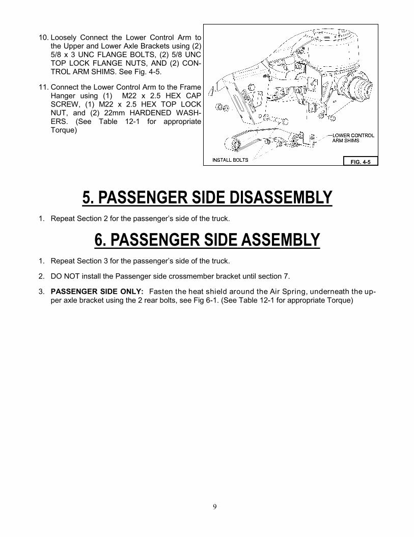
10. Loosely Connect the Lower Control Arm to the Upper and Lower Axle Brackets using (2) 5/8 x 3 UNC FLANGE BOLTS, (2) 5/8 UNC TOP LOCK FLANGE NUTS, AND (2) CON-TROL ARM SHIMS. See Fig. 4-5.
11. Connect the Lower Control Arm to the Frame Hanger using (1) M22 x 2.5 HEX CAP SCREW, (1) M22 x 2.5 HEX TOP LOCK NUT, and (2) 22mm HARDENED WASH-ERS. (See Table 12-1 for appropriate Torque)
5. PASSENGER SIDE DISASSEMBLY 1. Repeat Section 2 for the passenger’s side of the truck.
6. PASSENGER SIDE ASSEMBLY 1. Repeat Section 3 for the passenger’s side of the truck.
2. DO NOT install the Passenger side crossmember bracket until section 7.
3. PASSENGER SIDE ONLY: Fasten the heat shield around the Air Spring, underneath the up-per axle bracket using the 2 rear bolts, see Fig 6-1. (See Table 12-1 for appropriate Torque)
FIG. 4-5

10
FIG. 6-1
11
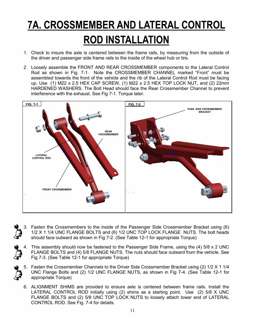
7A. CROSSMEMBER AND LATERAL CONTROL
ROD INSTALLATION 1. Check to insure the axle is centered between the frame rails, by measuring from the outside of
the driver and passenger side frame rails to the inside of the wheel hub or tire.
2. Loosely assemble the FRONT AND REAR CROSSMEMBER components to the Lateral Control Rod as shown in Fig. 7-1. Note the CROSSMEMBER CHANNEL marked “Front” must be assembled towards the front of the vehicle and the rib of the Lateral Control Rod must be facing up. Use (1) M22 x 2.5 HEX CAP SCREW, (1) M22 x 2.5 HEX TOP LOCK NUT, and (2) 22mm HARDENED WASHERS. The Bolt Head should face the Rear Crossmember Channel to prevent interference with the exhaust. See Fig 7-1. Torque later.
3. Fasten the Crossmembers to the inside of the Passenger Side Crossmember Bracket using (6) 1/2 X 1 1/4 UNC FLANGE BOLTS and (6) 1/2 UNC TOP LOCK FLANGE NUTS. The bolt heads should face outward as shown in Fig 7-2. (See Table 12-1 for appropriate Torque)
4. This assembly should now be fastened to the Passenger Side Frame, using the (4) 5/8 x 2 UNC FLANGE BOLTS and (4) 5/8 FLANGE NUTS. The nuts should face outward from the vehicle. See Fig 7-3. (See Table 12-1 for appropriate Torque)
5. Fasten the Crossmember Channels to the Driver Side Crossmember Bracket using (2) 1/2 X 1 1/4 UNC Flange Bolts and (2) 1/2 UNC FLANGE NUTS, as shown in Fig 7-4. (See Table 12-1 for appropriate Torque)
6. ALIGNMENT SHIMS are provided to ensure axle is centered between frame rails. Install the LATERAL CONTROL ROD initially using (2) shims as a starting point. Use (2) 5/8 X UNC FLANGE BOLTS and (2) 5/8 UNC TOP LOCK NUTS to loosely attach lower end of LATERAL CONTROL ROD. See Fig. 7-4 for details.
PASS. SIDE CROSSMEMBER BRACKET
FIG. 7-2
LATERAL CONTROL ROD
FRONT CROSSMEMBER
REAR CROSSMEMBER
FIG. 7-1

12
7B. STABILIZER BAR INSTALLATION
1. Install the Stabilizer bar with the center bend pointing up, away from the pinion. Loosely fasten to the Frame Hangers using the (2) M22 x 2.5 HEX CAP SCREWS, (2) M22 x 2.5 HEX TOP LOCK NUTS, and (4) 22mm HARDENED WASHERS. (See Table 12-1 for appropriate Torque)
2. Apply Lithium grease, or other lubricant, to the inside of the polyurethane D bushings (this will re-duce any potential noise transmission). Place the polyurethane D bushings over the bar in the ap-propriate locations on the Upper Axle brackets, and loosely fasten to the Upper Axle Mounts using the stabilizer bar mount clamp and (4) 5/8 x 2 UNC FLANGE BOLTS, (4) 5/8 UNC TOP LOCK FLANGE NUTS AND (4) STABILIZER BAR SHIMS (2 for each side). See Figure 7-5.
NOTE: Inspect Lateral Control Rod and Stabilizer Bar for any interference with other compo-nents, paying close attention to clearance with any flexible components such as brake and fuel lines.
SWAY BAR SHIMS
DRIVER SIDE CROSSMEMBER
BRACKET
FIG. 7-4 FIG. 7-3
5/8 X 2 UNC FRAME BOLTS
CAUTION: Ensure (2) M22 HEX BOLTS are installed with nut on D-BRACKET side as shown in
Fig. 7-5 and 7-6. Interference with AIRSPRING could occur if orientation is not as shown.

13
CENTER BEND UP
FIG. 7-5
SWAY BAR BUSHING
SWAY BAR SHIMS
SWAY BAR MOUNT CLAMP
IMPORTANT: Ensure (2) M22 HEX BOLTS are installed with nut on D-BRACKET side as shown in
Fig. 7-5 and 7-6. Interference with AIRSPRING could occur if orientation is not as shown.
FIG. 7-6
14
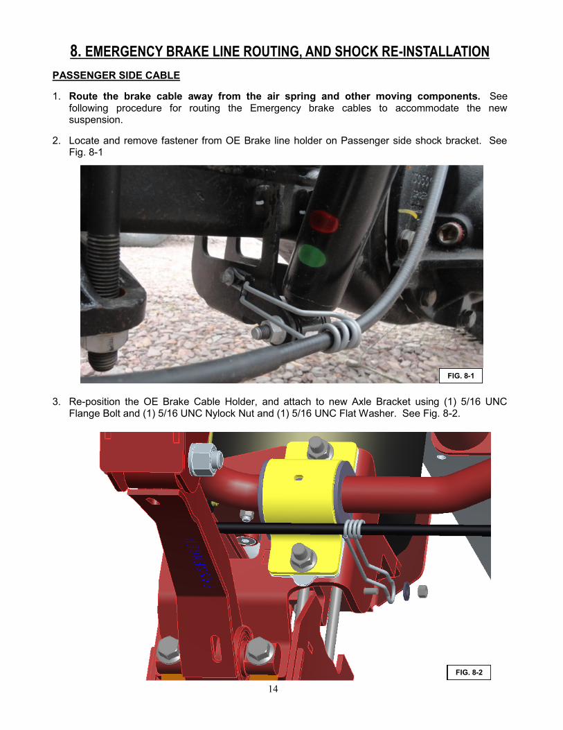
8. EMERGENCY BRAKE LINE ROUTING, AND SHOCK RE-INSTALLATION PASSENGER SIDE CABLE
1. Route the brake cable away from the air spring and other moving components. See following procedure for routing the Emergency brake cables to accommodate the new suspension.
2. Locate and remove fastener from OE Brake line holder on Passenger side shock bracket. See Fig. 8-1
3. Re-position the OE Brake Cable Holder, and attach to new Axle Bracket using (1) 5/16 UNC Flange Bolt and (1) 5/16 UNC Nylock Nut and (1) 5/16 UNC Flat Washer. See Fig. 8-2.
FIG. 8-1
FIG. 8-2

15
4. Locate and reposition Brake Cable Holder on under-side of driver side frame rail, as shown in Fig. 8-3. Use Cable Ties as needed to hold all wires away from components.
5. Route OE Brake Cable through supplied P-Clip, and attach to inside of Driver Side Hanger Bracket as shown in Fig. 8-4 using (1) 1/4 UNC Hex Bolt and (1) 1/4 UNC Nylock Nut
FIG. 8-3
FIG. 8-4

16
DRIVER SIDE CABLE
1. Route the brake cable away from the air spring and other moving components. See following procedure for routing the Emergency brake cables to accommodate the new suspension.
2. Re-install Brake Cable Holder into OE position, using original fasteners, as shown in Fig. 8-5.
3. Route OE Brake Cable through supplied P-Clip, and attach to outside of Driver Side Hanger Bracket as shown in Fig. 8-6 using (1) 1/4 UNC Hex Bolt and (1) 1/4 UNC Nylock Nut.
FIG. 8-5
FIG. 8-6

17
4. Install New Shock Absorbers supplied with with this kit, re-use OE Fasteners.
FIG. 8-7

18
9. AIR CONTROL AND ELECTRICAL SYSTEM ASSEMBLY
1. Instructions for mounting the Air Control Box and routing the airlines can be found in the Air Control Kit installation instructions.
2. For suspensions using the electronic height control system (800M1400), refer to the Electronic Air Kit Manual. With the electronic air kit, use the provided 3/8” tubing elbow fittings in the air springs.
3. For systems using the Mechanical Height Control Valve Kit (800M1060), mount (1) Valve Bracket to the driver side frame hanger using (2) 3/8 x 1 UNC FLANGE BOLTS, and (2) 3/8 UNC TOP LOCK FLANGE NUTS. Mount the Height Control Valve to the inside of the Mount Bracket using (2) 1/4 UNC HEX NYLOC NUTS. Undo the 1/4 UNC HEX NUT and Lock Washer on the free end of the linkage and connect the linkage to the tab on the Upper Axle Bracket. See Fig. 9-1. For suspensions using dual mechanical valve kits, repeat installation for the Passenger side. With the mechanical valve kit, install the provided 1/4” tubing elbow fittings in the air springs.
CAUTION! Route all airline away from exhaust, moving parts, and sharp objects. Be careful not to crimp the edges of the tubing. When
installing the airline, fully insert into fitting and give a slight pull to seat properly and to be sure airline will not pull out.
CAUTION! All wiring should be routed and secured neatly to avoid any functional or visual issues. Under hood and under-body wire
routings should be clear of sharp edges (3/4 inches minimum) and direct sources of heat (4 inches minimum). Wiring located in the passenger compartment should be routed away from high temperature areas over the muffler. Wiring should not be routed through wheel well areas where it may be damaged by tire or road debris, and it should not be routed over the exhaust system. Wiring should not contact the brake lines or fuel lines.

19
10. AXLE ALIGNMENT 1. To adjust front-to-rear axle alignment, remove shims to both the lower control arm and sway bar
bushing on the side (driver or passenger) that needs to be moved forward. Note that both components (lower control arm and sway bar) need to be moved together to ensure proper suspension geometry.
2. To adjust pinion angle, remove shims from both sides (driver and passenger) of the sway bar bushing (to increase pinion angle) or lower control arm (to decrease pinion angle).
3. To adjust side-to-side axle location, add or remove shims from the lateral control rod.
4. After alignment is complete, measure and mark dimensions on Fig. 10-1.
FIG. 9-1

20
11. FINAL INSPECTION CHECKLIST
Air System Start Up and Check
Remove all jacks and air system up by either using the fill valve on the air tank or by starting the vehicle and allowing the compressor to fill the system. If available, fill the air tank using the supplied Schraeder valve so that the compressors are not taxed too much by running for a long period of time.
Set Ride Height to 8.00 inches (see Fig. 11-1) according to the instructions in your air control
kit.
Bushing Bolts Final Torque
With the suspension at design height torque all bushing fasteners. This will include all fasteners for the Control Arm, Sway Arm and LCR bushings. (See Table 12-1 for appropriate Torque) - Mark all fasteners with a paint pen as they are torqued.
Recheck the air spring design height and repeat the above setting procedure if the design
height needs to be adjusted.
FIG. 11-1

21
Move the suspension throughout its entire range of motion, by inflating and deflating the air springs to achieve full travel. Check for any interferences with the lateral control rod, axle, shocks, exhaust, frame, brake lines (especially on the driver side), fuel lines, etc. Reconnect the valve/sensor linkage to the lever. Note: if contacting the brake lines, hand caulk the line to make clearance at least 1/4”.
Recheck all fasteners for specified torque.
Double check all electrical connections and wire routings.
IMPORTANT! Check all fittings and airlines for air leaks.
Reinstall the chassis body (if applicable).
Measure and record wheelbase and centering dims on following page.
12. OPERATION GUIDELINES After all final checks are complete, it is recommended to complete a full four- wheel alignment
and drive line angle check. The pages following the installation instructions describe the proper method for checking driveline angles. Note: improper driveline angles may have a detrimental effect on ride, u-joints, and transmission. If any driveline vibration (or out of spec. angle measurement) occurs, use factory axle seat shims to modify driveline angle.
IMPORTANT! During servicing check tightness of all fasteners and for any air system leaks.
IMPORTANT! Immediate corrective action should be taken if malfunctions occur.
FIG. 11-2

22
TORQUE TABLE (Table 12-1)
LOCATION FASTENER TORQUE
FRAME HANGER 9/16 UNF NUTS 134 FT-LBS
FRAME HANGER 5/8 UNC NUTS 200 FT-LBS
DRIVER SIDE AXLE BRACKET AT OE D-BUSHING LO-CATION
10 mm OE BOLTS 53 FT-LBS
AXLE BRACKET (LONG BOLTS) 1/2 UNC NUTS 106 FT-LBS
AIR SPRING ADAPTER PLATES 3/8 UNC NUTS 31 FT-LBS
CROSSMEMBER 1/2 UNC NUTS 100 FT-LBS
STABILIZER BAR D-BUSHING MOUNTS 5/8 UNC NUTS 200 FT-LBS
LOWER CONTROL ARM AT AXLE BRACKET 5/8 UNC NUTS 200 FT-LBS
AIR SPRING TOP STUD 1/2 UNC JAM NUT 30 FT-LBS
AIR SPRING TOP STUD 3/4 UNF JAM NUTS 50 FT-LBS
STABILIZER BAR BUSHINGS AND CONTROL ARM AT FRAME HANGER
M22 X 2.5 NUTS 610 FT-LBS
LATERAL CONTROL ROD (PASS.) M22 X 2.5 NUTS 610 FT-LBS
LATERAL CONTROL ROD (DRIVER) 5/8 UNC NUTS 200 FT-LBS
AIRSPRING ADAPTER TO UPPER AXLE BRACKET 3/8 UNC FLAT HEAD BOLTS 30 FT-LB
AIRSPRING ADAPTER TO AIRSPRING PISTON BOLTS 1/2 UNC FLAT HEAD BOLTS 35 FT-LBS
UPPER SHOCK NUT 12MM HEX FLANGE NUT 52 FT-LBS
LOWER SHOCK NUT 12MM HEX FLANGE NUT 66 FT-LBS
FIG. 12-2

23
13. SERVICE & MAINTENANCE The UltraRide suspension needs no lubrication and little maintenance. The following components should be checked at the time the truck is being serviced. However, immediate corrective action should be taken if a serious malfunction occurs. See Exploded Assembly Figure 13-2 for details.
Note: It is important to release any moisture contained within the air reservoir on a daily basis. See Air Kit Manual for details. Not releasing the moisture on a regular basis will cause the drain valve to not operate properly, and may cause the valve to malfunction. Excess moisture in the system can also cause premature failure of other components including the tank itself. AIR SPRING SERVICE The air spring can be serviced without removing the axle brackets from the axle. Simply unbolt the adapter plate from the Upper Axle Mount, and also detach the air spring bead plate from the Frame Hanger. (See figure 13-1). SERVICE & MAINTENANCE CHECK LIST Check and document OE rear axle alignment Verify Design Height at 8.0 inches Verify suspension function via dump and reinflation Check for air leaks and system integrity
CAUTION! If maintenance or service is to be done on the air system, be sure to drain all air from system. Serious injury could occur if components are removed while system is full of air.
FIG. 13-1 AIR SPRING SERVICE

24
Ult
raR
ide
® —
FO
RD
F450/5
50
B
AS
E S
US
PE
NS
ION
P
AR
TS
LIS
TIT
EMP
AR
T N
UM
BER
DES
CR
IPTI
ON
QTY
.IT
EMP
AR
T N
UM
BER
DES
CR
IPTI
ON
QTY
.
111
0305
01SP
RIN
G-A
IR2
2614
80-2
004
5/8
UN
C T
OP
LO
CK
FL
NU
T (G
R G
) O
&P
30
212
1005
29SH
OC
K A
BSO
RB
ER2
2714
8710
005/
16 T
YPE
A P
LAIN
WA
SHER
1
313
02-5
091
ELB
OW
, 1/4
TB
1/4
M-N
PT,
PU
SH-I
N D
OT
228
1487
1800
9/16
TYP
E A
PLA
IN W
ASH
ER8
413
02-5
104
ELB
OW
-3/8
TB
, 1/4
M-N
PT
229
1489
2200
WA
SHER
-HA
RD
ENED
, 22m
m10
514
01-0
808
1/4
X 1
UN
C H
EX C
AP
SC
R (
GR
5)
230
1500
-084
3B
USH
ING
-SW
AY
BA
R, P
OLY
UR
ETH
AN
E2
614
01-1
008
5/16
X 1
UN
C H
EX C
AP
SC
R (
GR
5)
131
1500
-086
51/
2 SS
CU
SHIO
NED
CA
BLE
CLA
MP
2
714
0418
149/
16 X
1 3
/4 U
NF
HEX
CA
P S
CR
(G
R 8
)4
3280
0018
19SH
IM-L
ATE
RA
L C
ON
TRO
L R
OD
6
814
0622
26H
EX C
AP
SC
REW
, M22
X 2
.5 X
130
, CLA
SS 1
0.9,
O&
P5
3380
0019
54C
LAM
P-M
OU
NT,
SW
AY
BA
R2
914
0B-1
008
5/16
X 1
UN
C H
EX C
AP
SC
R (
GR
8)
O&
P1
3480
0019
60B
RA
CK
ET-M
OU
NT,
CR
OSS
MEM
BER
1
1014
0B-1
664
1/2
X 8
UN
C H
EX C
AP
SC
R (
GR
8)
O&
P8
3580
0019
62B
RA
CK
ET-M
OU
NT,
LA
TER
AL
CO
NTR
OL
1
1114
17-1
212
3/8
X 1
1/2
UN
C S
OC
FLA
T C
SK H
D C
AP
SC
REW
436
8000
1963
SHIM
-SW
AY
BA
R4
1214
1716
081/
2 X
1 U
NC
SO
C F
LAT
CSK
HD
CA
P S
CR
EW4
3780
0019
74SW
AY
BA
R A
SSEM
BLY
1
1314
1A-1
610
1/2
X 1
1/4
UN
C F
LAN
GE
BO
LT (
GR
8)
O&
P8
3880
0019
79SH
IELD
- H
EAT
1
1414
1A-2
012
5/8
X 1
1/2
UN
C F
LAN
GE
BO
LT (
GR
8)
O&
P14
3980
0019
81B
RA
CK
ET-M
OU
NT,
LA
TER
AL
CO
NTR
OL
1
1514
1A-2
016
5/8
X 2
UN
C F
LAN
GE
BO
LT (
GR
8)
O&
P10
4080
0029
86P
LATE
-AD
AP
TER
, AIR
SP
RIN
G1
1614
1A-2
024
5/8
X 3
UN
C F
LAN
GE
BO
LT (
GR
8)
O&
P6
4180
0029
87P
LATE
-AD
AP
TER
, AIR
SP
RIN
G1
1714
70-1
000
5/16
UN
C H
EX N
UT
(GR
B)
142
800M
1057
LATE
RA
L C
ON
TRO
L R
OD
1
1814
74-1
600
1/2
UN
C H
EX J
AM
NU
T2
4380
0M10
58B
RA
CK
ET-M
OU
NT,
CR
OSS
MEM
BER
1
1914
75-2
400
3/4
UN
F H
EX J
AM
NU
T2
4481
0M01
13B
RA
CK
ET-M
OU
NT,
FR
AM
E1
2014
76-2
207
HEX
TO
P L
OC
K N
UT,
M22
X 2
.5, C
LASS
10
545
810M
0114
BR
AC
KET
-MO
UN
T, F
RA
ME
1
2114
7718
019/
16 U
NF
HEX
TO
P L
OC
K N
UT
(GR
C)
446
820M
0047
CO
NTR
OL
AR
M1
2214
78-0
800
1/4
UN
C H
EX N
YLO
CK
NU
T (G
R B
)2
4782
0M00
48C
ON
TRO
L A
RM
1
2314
78-1
000
5/16
UN
C H
EX N
YLO
CK
NU
T (G
R B
)1
4883
0M00
03B
RA
CK
ET-M
OU
NT,
LO
WER
AX
LE2
2414
78-1
200
3/8
UN
C H
EX N
YLO
CK
NU
T (G
R B
)4
4983
0M00
07B
RA
CK
ET-M
OU
NT,
UP
PER
AX
LE1
2514
80-1
604
1/2
UN
C T
OP
LO
CK
FL
NU
T (G
R G
) O
&P
1650
830M
0008
BR
AC
KET
-MO
UN
T, U
PP
ER A
XLE
1
25
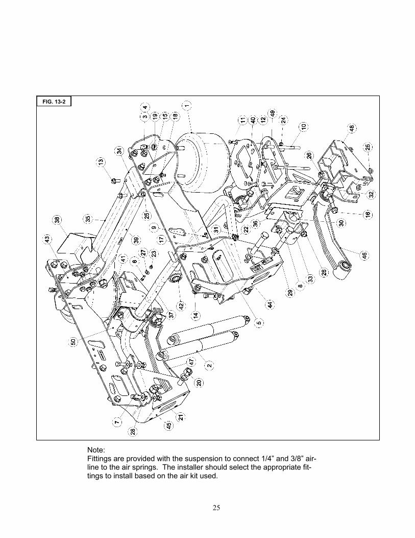
FIG. 13-2
Note: Fittings are provided with the suspension to connect 1/4” and 3/8” air-line to the air springs. The installer should select the appropriate fit-tings to install based on the air kit used.

26
Next 3 pages taken from Ford MVE Ship Thru Guide.
Guideline -Driveline Angles
After vehicle build is complete, the driveline angles must meet the following "rules", both at unloaded, and fully-loaded, vehicle attitudes .
Rule #1: The NET OPERATING ANGLE, at any individual joint, must be at least 1/2 degree, and not to exceed 3 degrees. The net operating angle at any individual joint on an F Super Duty (F250, F350, F450, F550) must not exceed 4 degrees. The preferred maximum angle is 2 degrees.
The NET OPERATING ANGLE (e) at any one joint is the combination of the joint angles in both the side view and the plan (top) view. This NET OPERATING ANGLE (e) equals:
080708 80001970-1

27
080708 80001970-1

28
MINIMUM UNIVERSAL JOINT OPERATING ANGLE: A slight angle is required to prevent universal joints from brinelling. Therefore, a minimum op-erating angle of 1/2 degree is required. MAXIMUM UNIVERSAL JOINT OPERATING ANGLE: Universal joint operating angles can be quite high, sometimes as high as 12 degrees. But to get a vehi-cle to operate successfully above 3 degrees often requires larger universal joints, double cardan or constant ve-locity joints, or restrictions on operating speed. A reduction in universal joint life becomes noticeable when they are operated at more than 3 degrees if precautions are not taken. That having been stated, the F Super Duty series tolerate angles up to 4 degrees. However, maximum angles of 2 degrees are preferable for all vehicles. Two shafts connected with a single cardan joint and turning at a constant speed with no joint angle, have. no angular acceleration that could cause a vibration. When there is an angle between them and the input shaft is turning at a constant speed, the driven shaft is forced to continuously accelerate and decelerate, twice per revolution , creating a vibration . If the speed changes are small, the vibration is not objectionable. The guidelines in this appendix limit driveline angular acceleration to a maximum of 400 radians per second per sec-ond. This is the requirement for all Ford trucks . (SAE specifies 500.) Some modified drivelines have been meas-ured at over 11,000 radians per second per second causing driveline failures at very low mileage. DRIVELINE ANGLE MEASUREMENT: Driveline angle measurements should be made with the vehicle supported by the tires and resting on a level surface . Avoid hoisting a vehicle by the frame since this will distort the chassis enough to make any meas-urements inaccurate. MATCH MOUNTING DRIVESHAFTS TO THE REAR AXLE: Runout is measured on OEM rear axle input shafts and the maximum measurement is shown with a dot or other
marking on the yoke or pilot bearing flange. The OEM driveshafts may also be marked with indicative marking on the "light"
side. When the parts are assembled , the marks are aligned to aid the overall system balance. Vehicle modifiers should look
for these alignment marks and maintain this match when the drivetrain is reassembled after modification. Remanufactured or
modified driveshafts should also have their "light" sides matched to the mark on the yoke or pilot bearing flange.
DRIVELINE VIBRATION DAMPERS: Driveline vibration dampers are sometimes added to driveshafts or axles to reduce noise, vibration, and harshness (NVH). If the chassis has these devices when it is received , they should be retained on the modified chassis. USE OF DOUBLE CARDAN UNIVERSAL JOINTS FOR GREATER DRIVE ANGLES: In general , the use of these joints can allow increased drive angles up to as much as 8 degrees. How-ever, when used at the rear of a coupling shaft a double cardan universal joint will prevent cancellation from oc-curring at the forward end of the shaft. Therefore the single cardan joint must still be maintained at less than 3 degrees (or 4 degees for the F Super Duty series).
GENERAL COMMENTS:
It is good practice, for any chassis that will have a driveline modification, to measure and record the driveline angles
in each of the following conditions for later comparison. A. The chassis as first received from Ford(note that the drive angles may not conform exactly to this bulletin in this incomplete condition). B. The completed vehicle, unloaded.
C. The completed vehicle loaded to GVWR with maximum front GAWR. D. The completed vehicle loaded to GVWR with maximum rear GAWR.
080708 80001970-1
29
100616
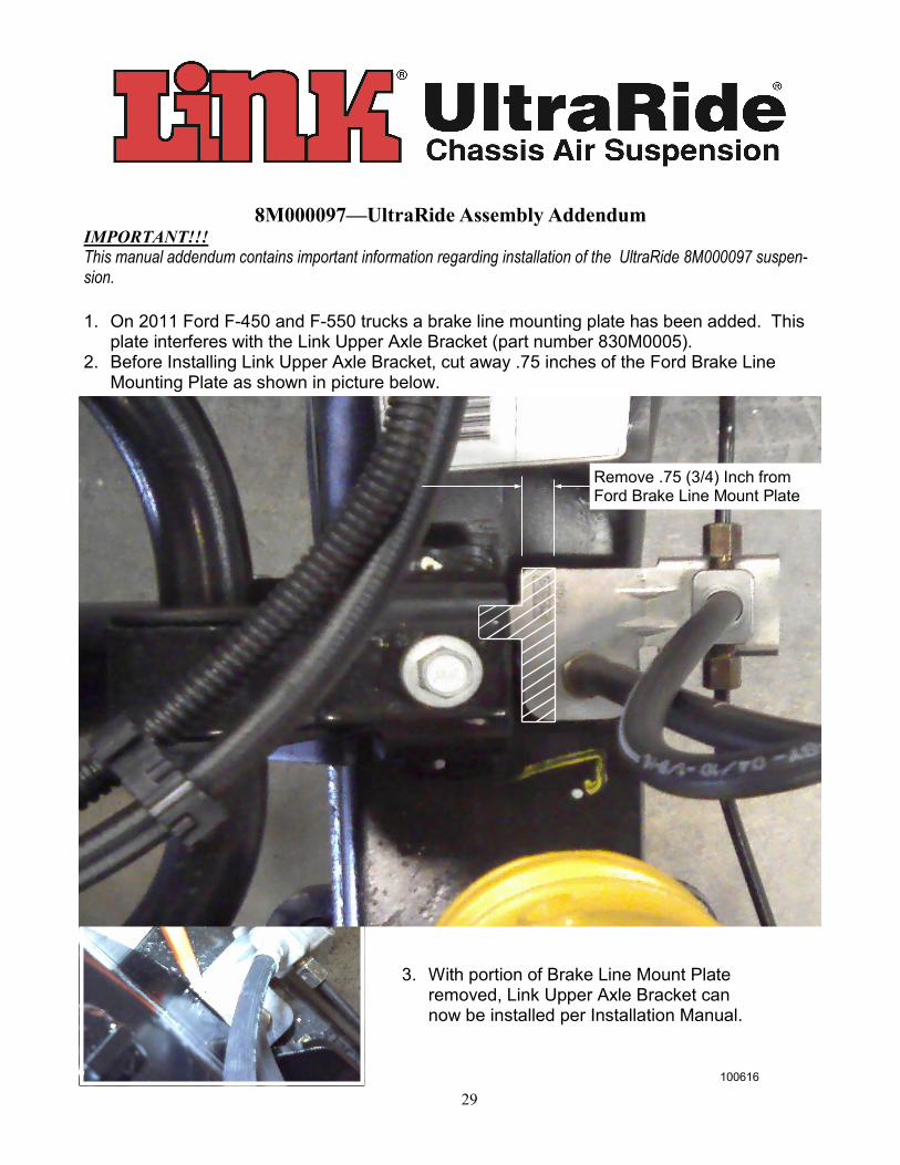
3. With portion of Brake Line Mount Plate removed, Link Upper Axle Bracket can now be installed per Installation Manual.
8M000097—UltraRide Assembly Addendum IMPORTANT!!!
This manual addendum contains important information regarding installation of the UltraRide 8M000097 suspen-sion.
1. On 2011 Ford F-450 and F-550 trucks a brake line mounting plate has been added. This
plate interferes with the Link Upper Axle Bracket (part number 830M0005). 2. Before Installing Link Upper Axle Bracket, cut away .75 inches of the Ford Brake Line
Mounting Plate as shown in picture below.
Remove .75 (3/4) Inch from Ford Brake Line Mount Plate

30
Link Mfg. Ltd. 223 15th St. NE
Sioux Center, IA USA 51250-2120
(712) 722-4874