Embed Size (px)
Citation preview
A Software Defined Radio
Expert Electronics2015
V1.1
SunSDR2DUC/DDC HF/6M/VHF SDR Transceiver
PRO
DUC/DDC HF/6M/VHF SDR Transceiver
PHONES MIC1 MIC2PWR
EExpert ElectronicsSunSDR2
PRO
Hardware manual
Expert Electronics SunSDR2 PRO transceiver
Contents
1. Operating rules........................................................................................................................32. Technical characteristics.........................................................................................................53. Local operation.......................................................................................................................64. Remote operation....................................................................................................................85. Operation...............................................................................................................................105.1 Operating controls...............................................................................................................105.2 Default Settings...................................................................................................................136. Terminal descriptions............................................................................................................146.1 EXT CTRL pinout...............................................................................................................146.2 MIC1 pinout........................................................................................................................156.3 MIC2 pinout........................................................................................................................156.4 PTT footswitch cable pinout...............................................................................................166.5 CW-keyer connector pinout................................................................................................176.5.1 Changing of CW Paddle Polarity.....................................................................................177. Regulatory requirements.......................................................................................................18

Expert Electronics SunSDR2 PRO transceiver
IMPORTANT
READ THIS INSTRUCTION MANUAL CAREFULLY before attempting to operate the transceiver.
SAVE THIS INSTRUCTION MANUAL. This manual contains important safety and operating instructions for the SunSDR2-PRO.
1. Operating rules• Visually inspect the SunSDR2 PRO transceiver for the absence of mechanic damages before
connecting it to PC;
• Learn attentively the manual, before using the Transceiver. Connecting and operation of theTransceiver without the instructions can bring to the fatal errors;
• If Transceiver was held in the climatic conditions, different from the operational, it isrecommended not to switch it on within 2 hours holding it in operational conditions;
• Connecting the Transceiver to a PC should be done in accordance with the connection diagram,given in the Manual;
• Check the presence of the ground connection of the PC and the ground wire of the antennaconnector (SMA) of the Transceiver before switching;
• It is forbidden to connect the Transceiver to PC with the voltage presence on it or in the switchedcondition;
• It is forbidden to use the power supply with the voltage more that +16 V. Remember! Thetransceiver's power is the voltage direct current!
• Before connecting the external devices to connector EXT CTRL read the Manual, learn the tablesand the diagrams of connecting the external devices;
• Remember! The transistor switches have the limitations over supply voltage and current, goingthrough them. The power swap is forbidden;
• It is forbidden to use the Transceiver in the temperatures lower than 0ºC (32ºF) and higher than+75ºC(167ºF);
• It is forbidden to use and store the Transceiver in the dusted rooms and on exposure to directsunlight;
• Avoid exposure of the atmospheric precipitations on the Transceiver. Never spill any liquids(especially aggressive) on the Transceiver;
• It if forbidden to use the Transceiver during storms;
• Don't open the Transceiver. It contains the radio elements, which have the high-sensitivity to thestatic electricity. This document contains all the necessary information about the internal designto satisfy the curiosity of Users. To repair the Transceiver ask the manufacturer;
• Always unplug the Transceiver's antenna, if you don't control it or if there appear a danger ofatmospheric electricity damage;
• Save the Transceiver, cables and wires from the influence of the magnetic pickups (emergencystates), out controlled currents and voltages and the domestic animals;
3

Expert Electronics SunSDR2 PRO transceiver
• To exclude the damage of the devices and not to produce the harmful interference on air don'tallow to control the Transceiver people with the doubtful reputation;
• Keep out of the reach of children.
4

Expert Electronics SunSDR2 PRO transceiver
2. Technical characteristics
General coverage receiver in HF, MHz 0.09...65
General coverage receiver in VHF, MHz 95...148
Frequency coverage in HF in TX mode, MHz All HF and 6m amateur frequencies
Frequency coverage in VHF in TX mode, MHz 144...148
Sensitivity, uV 0,07
Maximum transmitter's output power in HF, W 15
Maximum transmitter's output power in VHF, W 7
Blocking dynamic range in HF mode (BDR), dB 129
Blocking dynamic range in VHF mode (BDR), dB >114
RF ADC clock frequency, MHz 160
RF ADC resolution, bit 16
RF DAC clock frequency, MHz 640
RF DAC resolution, bit 14
Recommended power supply, V 15
Supply voltage range, V 12...16
Local oscillator's stability, ppm +/- 0.5
Maximum consumption current, А 5
Built-in audio codec resolution, bit 24
ALC input voltage range, V 0..4
Dimensions, mm (inches) 165х165х35 (6” ½ x 6” ½ x 1” 3/8)
Operating temperature, ºC (ºF) 0(32) to +75(167)
Weight, kg (lbs) 1,5 (3.3)
5
Expert Electronics SunSDR2 PRO transceiver
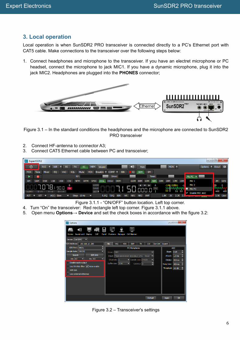
3. Local operationLocal operation is when SunSDR2 PRO transceiver is connected directly to a PC’s Ethernet port withCAT5 cable. Make connections to the transceiver over the following steps below:
1. Connect headphones and microphone to the transceiver. If you have an electret microphone or PCheadset, connect the microphone to jack MIC1. If you have a dynamic microphone, plug it into thejack MIC2. Headphones are plugged into the PHONES connector;
Figure 3.1 – In the standard conditions the headphones and the microphone are connected to SunSDR2PRO transceiver
2. Connect HF-antenna to connector A3;3. Connect CAT5 Ethernet cable between PC and transceiver;
Figure 3.1.1 - “ON/OFF” button location. Left top corner.4. Turn “On” the transceiver: Red rectangle left top corner. Figure 3.1.1 above.5. Open menu Options→ Device and set the check boxes in accordance with the figure 3.2:
Figure 3.2 – Transceiver's settings
6

Expert Electronics SunSDR2 PRO transceiver
6. In the main ExpertSDR2 software dialogue window specify the connector to which your microphoneis connected (see Figure 3.3 below);
Figure 3.3 – Selecting correct microphone inputs of the transceiver
7. Go to Sound Card menu and verify check box “Enable” is unchecked. See figure 3.4;
Figure 3.4 – Controlling the microphone inputs of the transceiver
8. Click OK. If everything is done correctly, you will see the air noise track on the panoramic display andhear the sound in the headphones.
7
Expert Electronics SunSDR2 PRO transceiver
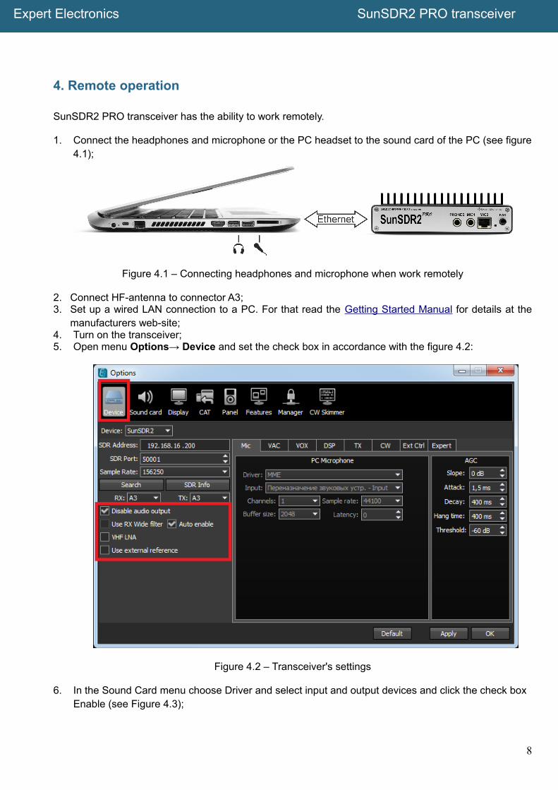
4. Remote operation
SunSDR2 PRO transceiver has the ability to work remotely.
1. Connect the headphones and microphone or the PC headset to the sound card of the PC (see figure4.1);
Figure 4.1 – Connecting headphones and microphone when work remotely
2. Connect HF-antenna to connector A3;3. Set up a wired LAN connection to a PC. For that read the Getting Started Manual for details at the
manufacturers web-site;4. Turn on the transceiver;5. Open menu Options→ Device and set the check box in accordance with the figure 4.2:
Figure 4.2 – Transceiver's settings
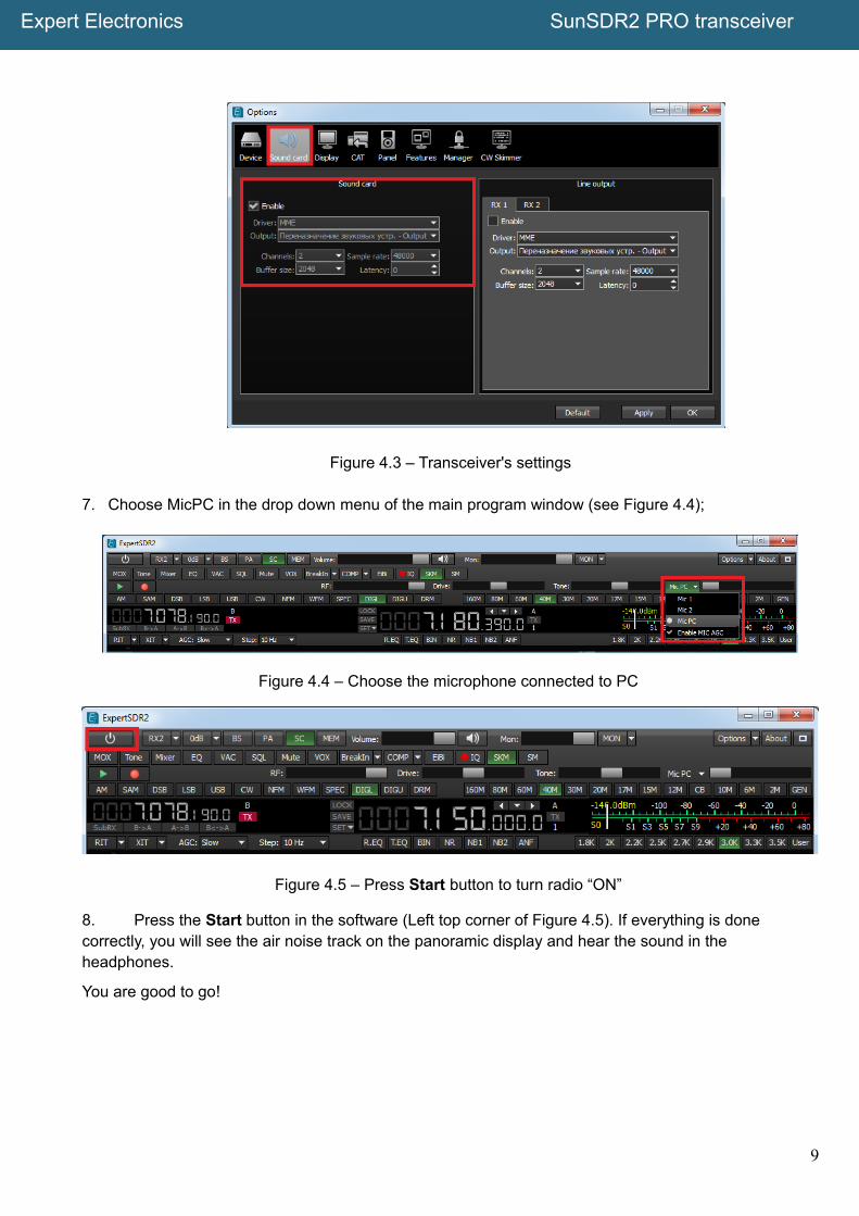
6. In the Sound Card menu choose Driver and select input and output devices and click the check box Enable (see Figure 4.3);
8
Expert Electronics SunSDR2 PRO transceiver
Figure 4.3 – Transceiver's settings
7. Choose MicPC in the drop down menu of the main program window (see Figure 4.4);
Figure 4.4 – Choose the microphone connected to PC
Figure 4.5 – Press Start button to turn radio “ON”
8. Press the Start button in the software (Left top corner of Figure 4.5). If everything is done correctly, you will see the air noise track on the panoramic display and hear the sound in the headphones.
You are good to go!
9

Expert Electronics SunSDR2 PRO transceiver
5. Operation
5.1 Operating controls
Transceiver SunSDR2 PRO has several external operating controls. Transceiver's front panel (seeFigure 5.1) has connectors for headphones and two types of microphones, dynamic and electret, LED toindicate the operation modes and power switch. Rests of operating controls are placed on the rear panel(see Figure 5.2).
Figure 5.1 – Front panel of the transceiver
Figure 5.2 – Rear panel of the transceiver
10

Expert Electronics SunSDR2 PRO transceiver
Pin out of the power connector (see Figure 5.3).
Figure 5.3 – The power connector pinout
Table 1 – Description of the operating controls
№ Operating controls description Comments
1. Jack for connecting the headphones Headphones with the resistance 16-32 Ohm oractive dynamics can be connected to this jack
2. Jack for connecting the electretmicrophone
Electret microphone of the PC's headset or similarcan be connected to this jack
3. Jack for connecting the dynamicmicrophone
This jack is intended to connect the dynamicmicrophone MH-31 or any other dynamicmicrophone with the connector RJ-45 andcorresponding pinout
4 Power indication LED This indicator displays operation modes of thetransceiver:- green color: LAN is active/connected;- orange color: WiFi is active/connected (whenthe transceiver has a WiFi option);- red color: transmit mode is “ON”;- blinking green or orange color: network setupstate, wait for a solid color.
5. Power button This button switches on and off the transceiver'spower
6. Connector for connecting of WiFiantenna
This connector is installed when the transceiverhas a WiFi(WLAN) option
7. Input of the external reference oscillator10MHz10 MHZ CMOS level input
Voltage with the amplitude of 10-13 dB/mW andfrequency 10MHz can be applied to this input.
Warning! Improper use or higher voltage maydamage the transceiver!
8. RX OUT Output of the internal receiver's front-end
Warning! Improper use or higher voltage maydamage the transceiver!
9. Connector of the ADC uncomplementedinput
This connector is intended for connection theexternal signal sources to the input of high-speedADC directly, bypass all the filters.
Warning! Improper use or higher voltage maydamage the transceiver!
10. Connector of the direct output of high-speed DAC
Connector is intended for direct connection of theexternal devices to the output of the high-speed
11

Expert Electronics SunSDR2 PRO transceiver
DAC, bypass all the filters, amplifiers, etc.
Warning! Improper use or higher voltage maydamage the transceiver!
11. Power connector Connector is intended for connection of DC powersource with voltage of up to +15V and maximumload current 5A.Transceiver schematic incorporates shutdowncircuit protecting device from the power polarityreversal.
12. LAN connector Connector is intended for connecting thetransceiver to the local network via LAN cable
13. Telegraph key connector (CW) Connector is intended for connection of thetelegraph key. Polarity of dots/dashes can bechanged in the software. See Page 17.
14. PTT footswitch connector Connector is intended for connecting the PTTfootswitch
15. External control connector (EXT CTRL) Connector is intended for controlling the externaldevices, pinout is shown at the figure 6.3
Warning! Improper use of this connector candamage keys with open collector and damage thetransceiver!
16. ALC input ALC input for external power amplifier
17. Connector A1 for VHF antenna Connector is intended for connection the VHFantenna. Antenna should be connected to thisconnector when receiving and transmitting signalswith the frequencies on 2m band.
Note! All the antennas from connectors A2 and A3should be disabled during the VHF receipt!
18,19.
Connectors A2 and A3 for HF antennas HF antennas should be connected to connectorsA2 and A3 when operating HF or 6m. Control ofthe antenna switch is done from ExpertSDR2software.
20. Button to reset transceiver’s IP-addresssettings to default settings
This button is intended to reset IP-address andUDP-ports of the transceiver to the default IPvalues: 192.168.16.200, ports: 50001, 50002.Instructions how to reset transceiver’s IP addressare provided in Clause 5.2.
21. Button to switch operating modesbetween LAN and WLAN (Wi-Fi)
This button is intended to switch the transceiverfrom LAN to WLAN. If WLAN option is notinstalled, transceiver will not operate when theWLAN mode is selected. Single pressing of thebutton changes operation mode.
12

Expert Electronics SunSDR2 PRO transceiver
5.2 Default Settings
Sometimes it is necessary to reset transceiver's settings. Follow steps below:
1. Switch off the transceiver's power supply with PWR switch;2. Press RST button on the rear panel of the transceiver and hold it. You will hear a light click;3. Switch “ON” transceiver’s power supply with PWR switch. The LED will blink different colors (greenand red);4. Release RST button;5. Wait until the LED turns to green color. Solid green color indicates the completion of the reset of thetransceiver's settings to default settings.
“Deep” reset. Follow steps below:
1. Switch off the transceiver's power supply with PWR switch ;2. Press simultaneously the buttons L/W and RST on the rear panel of the transceiver and hold them;3. Switch “ON” transceiver's power supply with PWR switch. The LED will blink different colors (greenand red);4. Release RST and L/W buttons;5. Wait till the LED turns to solid green color;6. Solid green color indicates the completion of the reset of the transceiver's settings to default settings.
After the reset procedure transceiver will have the IP-address by default 192.168.16.200 and ports50001 and 50002.
Warning! Do not switch “Off” transceiver's PWR button while LED is blinking.
After switching on the RST button won't be active. Pressing it doesn't have any effect.
13

Expert Electronics SunSDR2 PRO transceiver
6. Terminal descriptions
6.1 EXT CTRL pinout
onnector EXT CTRL is intended for control of external devices, such as power amplifiers, antennaswitching units and tuners, wide of narrow band-pass filters. Control is done directly from SDR-software.At figure 6.1 is given the layout of the connector at the transceiver's rear panel and its pin-out.
Figure 6.1 – Layout and pinout of the EXT CTRL connector. View from back of transceiver.
Table 2 – Pins description of the EXT CTRL connector
No. Pin Name Description
1. X1 – X7 Open collector’s pins (programmable I/O with software)
2. X8 Open collector’s pin for control of PTT for external PA
3. CP Protective diode pin
4. +12V Pin for power supply +12V, MAX current 0.5 A
Attention! Do not connect loads with current above 0.5 A, it willdamage transceiver.
5. G Transceiver's ground terminal
6. I1, I2 Button sensors, works on the input
7. RA, RB RS485 Interface
14

Expert Electronics SunSDR2 PRO transceiver
6.2 MIC1 pinout
Connector MIC1 is intended for connection the electret microphone, PC headset or any other electretmicrophone, which is intended to work with PC. Connector JACK6.3 to JACK 3.5 is used for connection(included into the set). Circuit diagram for the electret microphone is shown at the figure 6.2.
Figure 6.2 – JACK 6.3 мм connector pinout for connection to MIC1
6.3 MIC2 pinout
Dynamic microphones are less sensitive to the extraneous noises due to greater focus. Dynamicmicrophones have a higher speech quality and signal/noise ratio during operation.
MIC2 connector is intended to connect the dynamic microphones. This connector has a pinout whichcorresponds to the dynamic microphone. At the figures below you can find the appearance of dynamicmicrophone MD-15 (figure 6.3), PTT diagram (figure 6.4) and the direction of numbering (figure 6.5).
Figure 6.3 – The appearance of the PTT MD-15.
15
Expert Electronics SunSDR2 PRO transceiver
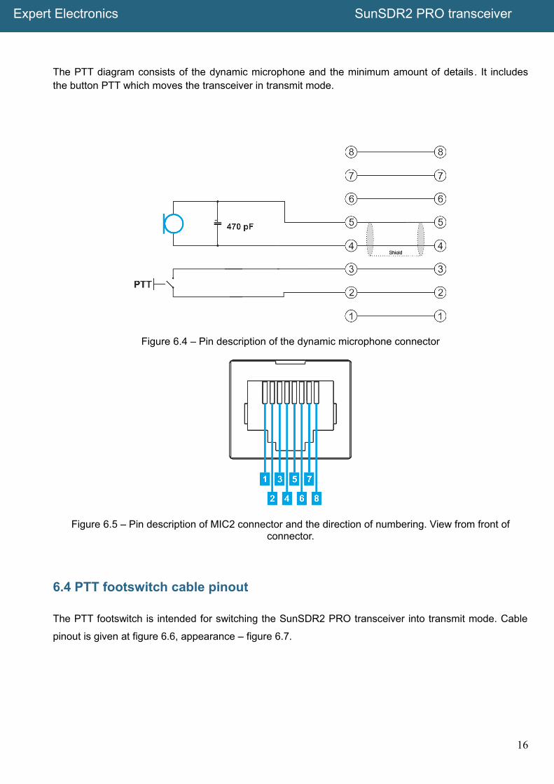
The PTT diagram consists of the dynamic microphone and the minimum amount of details. It includesthe button PTT which moves the transceiver in transmit mode.
Figure 6.4 – Pin description of the dynamic microphone connector
Figure 6.5 – Pin description of MIC2 connector and the direction of numbering. View from front ofconnector.
6.4 PTT footswitch cable pinout
The PTT footswitch is intended for switching the SunSDR2 PRO transceiver into transmit mode. Cable
pinout is given at figure 6.6, appearance – figure 6.7.
16
Expert Electronics SunSDR2 PRO transceiver
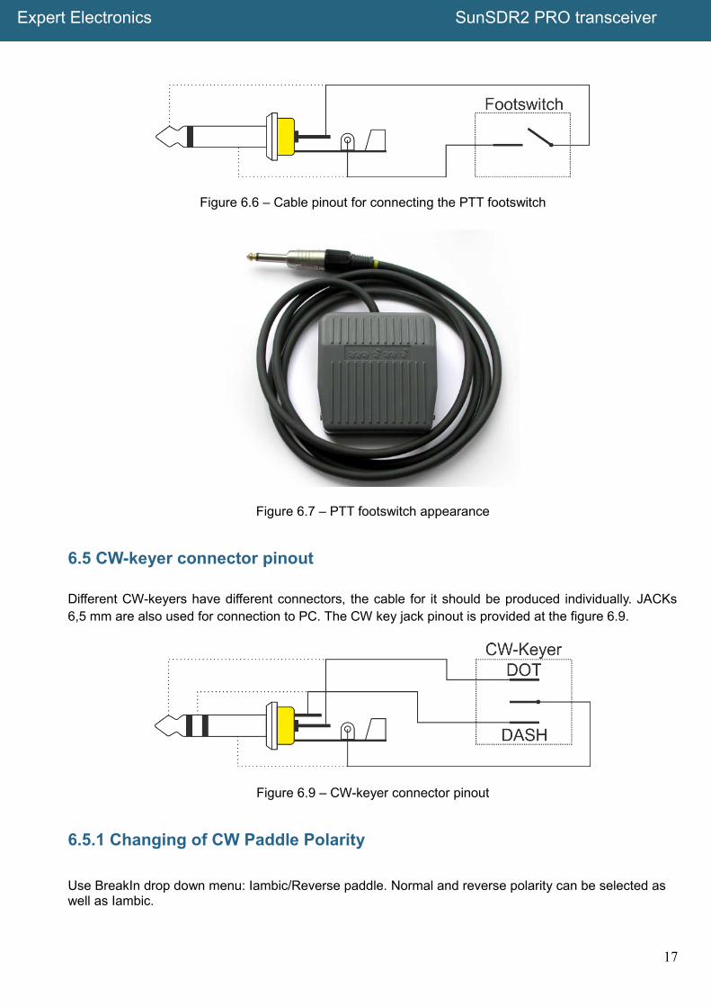
Figure 6.6 – Cable pinout for connecting the PTT footswitch
Figure 6.7 – PTT footswitch appearance
6.5 CW-keyer connector pinout
Different CW-keyers have different connectors, the cable for it should be produced individually. JACKs6,5 mm are also used for connection to PC. The CW key jack pinout is provided at the figure 6.9.
Figure 6.9 – CW-keyer connector pinout
6.5.1 Changing of CW Paddle Polarity
Use BreakIn drop down menu: Iambic/Reverse paddle. Normal and reverse polarity can be selected as well as Iambic.
17

Expert Electronics SunSDR2 PRO transceiver
7. Regulatory requirements
We Expert Electronics LLC. C6 ”V” Lesnaya Birzha St., Taganrog,Rostov Region, Russian Federation, 347900
declare that SunSDR2 PRO transceiver has been tested in accordance to essential protection requirements of theR&TTE Directive 1999/5/EC on the approximation of the laws of the Member States relating to Radio SpectrumMatters and found the rest results indeed meet the limitation of the relevant test standard(s) listed below:
EMC
EN 301 489-1: V 1.9.2 (2011)EN 301 489-15: V 1.2.1 (2002)
Radio Spectrum
EN 301 783-1: V 1.2.1 (2010)EN 301 783-2: V 1.2.1 (2010)
Type of Equipment: Base StationEquipment Class: B
The system is to be operated in accordance with the laws of the telecommunications regulatory agency in thecountry of use. A license is required to use this equipment, and the operator must comply with the nationalfrequency allocations for the county of use.
Testing Company: Worldwide Testing Service (Taiwan) Co., Ltd.Place of issue: 6F, NO.58, LANE 188, RUEY-KUANG RD., NEIHU, TAIPEI 114, TAIWAN, R.O.C.Date of testing: August 14, 2015Person Responsible: Rex Kao (Signature on file)
RoHS Directive
Expert Electronics LLC confirms that we place on the market products sourced from suppliers who have confirmedthat their products are RoHS compliant. Expert Electronics LLC declares that this equipment complies with therestriction of the use of certain hazardous substances in electrical and electronic equipment.
Waste Disposal
The device may not be disposed of with household waste! This device complies with EU Directive on Electronicand electrical equipment (WEEE regulation) and will therefore not be disposed of with household waste. Dispose ofthe device to your local collection points for electronic equipment!
18

Expert Electronics2015
© Copyright 2015, Expert Electronics LLC. All Rights Reserved.
DUC DDC SDR Series, SunSDR2 PRO Transceiver. Specifications are subject to change without notice or obligation and specifications are only guaranteed within the amateur radio bands.
V1.1 - 28.10.2015
www.eesdr.com