Embed Size (px)
Citation preview

Sunny Boy 3300TLTransformerless String Inverter
Operating Instructions Version 1.0 SB3300TL-11:FE1905TBE-SB33TL


SMA Technologie AG
Revision HistoryDocument number Changes Author
SB3300TL-11:FE1905 First Issue Riemenschneider
Operating Instructions SB3300TL-11:FE1905 Page 3

SMA Technologie AG
Page 4 SB3300TL-11:FE1905 Operating Instructions

SMA Technologie AG
Table of Contents1 Introduction. . . . . . . . . . . . . . . . . . . . . . . . . . . . . . . . 32 Safety Instructions . . . . . . . . . . . . . . . . . . . . . . . . . . . 53 Device Description . . . . . . . . . . . . . . . . . . . . . . . . . . . 7
3.1 Application of the Sunny Boy . . . . . . . . . . . . . . . . . . . . . . . . . 73.2 Device Design . . . . . . . . . . . . . . . . . . . . . . . . . . . . . . . . . . . . 83.3 Operating States . . . . . . . . . . . . . . . . . . . . . . . . . . . . . . . . . .10
3.3.1 Normal Operating States . . . . . . . . . . . . . . . . . . . . . . . .103.3.2 Critical Failure States . . . . . . . . . . . . . . . . . . . . . . . . . . .113.3.3 Uncritical Failure States. . . . . . . . . . . . . . . . . . . . . . . . . .113.3.4 Description of Operating States . . . . . . . . . . . . . . . . . . . .12
3.4 Status Messages on the Optional Display . . . . . . . . . . . . . . . .224 Configuration of the Display Language . . . . . . . . . . . 255 Service and Maintenance. . . . . . . . . . . . . . . . . . . . . 276 Plant Monitoring . . . . . . . . . . . . . . . . . . . . . . . . . . . 29
6.1 Sunny Data. . . . . . . . . . . . . . . . . . . . . . . . . . . . . . . . . . . . . .296.1.1 Sunny Data via Power Line . . . . . . . . . . . . . . . . . . . . . . .296.1.2 Sunny Data via RS232 . . . . . . . . . . . . . . . . . . . . . . . . . .306.1.3 Sunny Data via RS485 . . . . . . . . . . . . . . . . . . . . . . . . . .306.1.4 Sunny Data via Sunny Beam . . . . . . . . . . . . . . . . . . . . . .31
6.2 Sunny Beam . . . . . . . . . . . . . . . . . . . . . . . . . . . . . . . . . . . . .316.3 Sunny Boy Control Light. . . . . . . . . . . . . . . . . . . . . . . . . . . . .316.4 Sunny Boy Control . . . . . . . . . . . . . . . . . . . . . . . . . . . . . . . .326.5 Sunny Boy Control Plus . . . . . . . . . . . . . . . . . . . . . . . . . . . . .326.6 Sunny Data Control . . . . . . . . . . . . . . . . . . . . . . . . . . . . . . . .336.7 Sunny WebBox . . . . . . . . . . . . . . . . . . . . . . . . . . . . . . . . . . .346.8 Sunny Portal . . . . . . . . . . . . . . . . . . . . . . . . . . . . . . . . . . . . .346.9 Sunny TV . . . . . . . . . . . . . . . . . . . . . . . . . . . . . . . . . . . . . . .35
7 Technical Documentation . . . . . . . . . . . . . . . . . . . . . 377.1 Data PV-Generator Connection . . . . . . . . . . . . . . . . . . . . . . .377.2 Data Grid Connection . . . . . . . . . . . . . . . . . . . . . . . . . . . . . .377.3 Description of Device. . . . . . . . . . . . . . . . . . . . . . . . . . . . . . .387.4 Measurement Channels and Messages . . . . . . . . . . . . . . . . . .39
7.4.1 Measurement Channels. . . . . . . . . . . . . . . . . . . . . . . . . .397.4.2 Status Messages. . . . . . . . . . . . . . . . . . . . . . . . . . . . . . .407.4.3 Sunny Boy 3300TL Operating Parameters . . . . . . . . . . . .427.4.4 Precision of Measured Value Acquisition . . . . . . . . . . . . .447.4.5 Failure Messages . . . . . . . . . . . . . . . . . . . . . . . . . . . . . .45
7.5 Declaration of Conformity (CE) . . . . . . . . . . . . . . . . . . . . . . .497.6 Clean Report of Findings (Grid Guard) . . . . . . . . . . . . . . . . . .50
Operating Instructions SB3300TL-11:FE1905 Seite 1

SMA Technologie AG
8 Glossary . . . . . . . . . . . . . . . . . . . . . . . . . . . . . . . . . 519 Contact . . . . . . . . . . . . . . . . . . . . . . . . . . . . . . . . . . 55
Seite 2 SB3300TL-11:FE1905 Operating Instructions

SMA Technologie AG Introduction
1 IntroductionYou have decided to use one of the most advanced de-vices for modular PV-system technology by purchasinga Sunny Boy 3300TL.
The Sunny Boys comply with all regulations from theVDEW (Association of German Electricity Utilities) forsupplementary grid feeding to the low voltage electric-ity grid of the utility. This includes the regulations of theemployee association (Berufsgenossenschaft für Fein-mechanik und Elektrotechnik) concerning the „Indepen-dent Disconnection Device“ known as MSD (Mainsmonitoring device with allocated Switching Devices)and the regulations of the DIN VDE 0126. Further-more, the Sunny Boy complies with the according har-monized standards and the low voltage regulations as certified in the CE declaration(see chapter 7.5 "Declaration of Conformity (CE)" (page 49)).
This document contains the „Operating Instructions“ of the Sunny Boy 3300TL. Theyare meant as guidelines on how to use all functions of the Sunny Boy 3300TL opti-mally and how to extend your existing PV-plant.
This part of device documentation especially deals with those topics that are relevantto the operation of the Sunny Boy 3300TL. For the installation of the Sunny Boy3300TL please see the „Installation Guide“.
ErdschlussEarth Fault
Art
.-N
r.: 8
6-0
0
Operating Instructions SB3300TL-11:FE1905 Page 3
Introduction SMA Technologie AG
Page 4 SB3300TL-11:FE1905 Operating Instructions

SMA Technologie AG Safety Instructions
2 Safety InstructionsOpening the device and by that
• the electrical installation, • the repair or • the modification
of the Sunny Boy 3300TL may only be done by a qualified tech-nician. Even if there are no external voltages on the devicethere may be high voltages that are hazardous to touch.
The temperature of individual parts of the enclosure of theSunny Boy 3300TL – especially the one of the heat sinks – canreach 85 °C even in normal operation. There is a danger ofburning yourself when touching the Sunny Boy.
The Sunny Boy 3300TL is equipped with the self disconnecting electricitygrid „SMA grid guard“. The Sunny Boy 3300TL therefore complies withthe VDEW guidelines for grid interactive inverters and the DIN VDE 0126(4.99) specified in this regulation.
Operating Instructions SB3300TL-11:FE1905 Page 5
Safety Instructions SMA Technologie AG
Page 6 SB3300TL-11:FE1905 Operating Instructions

SMA Technologie AG Device Description
3 Device Description
3.1 Application of the Sunny BoyThe Sunny Boy 3300TL is used in order to convert DC power from photovoltaic mod-ules to AC voltage and subsequently feed this to the 230 V / 50 Hz utility. The tech-nical data is specified in chapter 7 "Technical Documentation" (page 37) of thisdocument.
Usage of the Sunny Boy 3300TL in any other applications will void the warranty.
ErdschlussEarth Fault
Art
.-N
r.: 8
6-0
0
PhotovoltaicModule
Sunny Boy 3300TL Utility
Operating Instructions SB3300TL-11:FE1905 Page 7

Device Description SMA Technologie AG
3.2 Device DesignWe have focused on a simple functional design when developing the Sunny Boystring inverters. In its basic design the Sunny Boy 3300TL does not need more thanthree LEDs for status display. A display unit is available. The display can already beinstalled when your Sunny Boy is delivered or installed later.
The Sunny Boy 3300TL will operate fully automatically without any modification orconfiguration as long as it is installed and commissioned according to the technicalspecifications. It can nevertheless be modified in terms of operating parameters if nec-essary. An additional communication interface is required for this, which also can beused in order to acquire operating data for performance evaluation. Please have alook at chapter 6 "Plant Monitoring" (page 29) for details.
MPP-Tracking
Step up converter Bridge
Earth fault-monitoring
Overvoltage-protection:
Thermallymonitoredvaristors
Optionaldisplay(IP65)
Optionalcommuni-
cationinterface:
RS232RS485
PowerlineRadio
Residualcurrent
measuring
AC
-term
inal+
Sunny Boy 3300TL enclosure IP65 (outside installation possible)
L
N
PE
DC
-Inpu
t with
2 p
lug
conn
ecto
r
SMAgrid guard
Page 8 SB3300TL-11:FE1905 Operating Instructions

SMA Technologie AG Device Description
All connections to the PV-strings and the public grid as well as the optional communi-cation cables are on the bottom of the Sunny Boy 3300TL.
DC + DC -
Cable opening for grid con-nection
Opening for optional communi-cation via radio, RS232 orRS485 (for PG 16)
Operating Instructions SB3300TL-11:FE1905 Page 9

Device Description SMA Technologie AG
3.3 Operating StatesThe different operating states are displayed with three LEDs in the lid of the SunnyBoy 3300TL.
You will find a complete description of all signal codes in chapter 3.3.4 "Descriptionof Operating States" (page 12). The operating states can be divided into three cate-gories:
3.3.1 Normal Operating StatesAs long as no LED or only the green LED is blinking, the Sunny Boy 3300TL is in oneof its normal operating states. If all three LEDs are on, the inverter is in its initializationphase which is a normal operating state as well. All other signals indicate a disturbedoperating state.
Especially in the first year after installation the operator of the plantshould regularly have a look at this display at different times of the dayand at different irradiation.
Photovoltaik-StringwechselrichterPhotovoltaic string inverter
Page 10 SB3300TL-11:FE1905 Operating Instructions

SMA Technologie AG Device Description
the PV-generator frowise be severly dama
3.3.2 Critical Failure StatesDue to a comprehensive safety concept, the number of critical operating states canbe reduced to one:
Input voltage exceeding specification
This is shown with the following blinking code of the yellow LED:
When the failure occurs,the yellow failure LED is onfor five seconds and thenstarts to send the blinkingcode by remaining off forthree senconds and blink-ing four times in short inter-vals. The code is sent threetimes. If the failure persiststhe code is repeated.
3.3.3 Uncritical Failure StatesAll other signaling codes show uncritical operating states that normally do not poseimminent danger of people or devices. However, their cause must be immediatelyfound and removed in order to avoid yield losses.
Despite all necessary precautions additional failures which can not be signaled (e. g.failure of the status display) can occur. In order to be able to detect such failures aswell, the operator should check the display of normal operating states for plausibilitybased on the explanations given in chapter 3.3.4 "Description of Operating States"(page 12). For example if the green LED is on at night, it indicates a failure in thesame way as if no LED is on in full sunlight.
More detailed diagnoses are possible by one of the communication interfaces de-scribed in chapter 6 "Plant Monitoring" (page 29).
Immediately disconnect The Sunny Boy can other
5s 3s 1s1s 1s 1sLED an LED aus
The yellow LED is blinking4 times in short intervals
The signal is repeated 3 times andthen starts from the beginning
Operating Instructions SB3300TL-11:FE1905 Page 11

Device Description SMA Technologie AG
3.3.4 Description of Operating StatesStand-by at Night
The Sunny Boy 3300TL is in so-calledstand-by operation. This state isreached if the input power at the in-verter is too low for feeding opera-tion (all string voltages are below125 V) and not sufficient for normaloperation.
InitializationThe on-board computer of the SunnyBoy 3300TL is in the initializationphase. The DC input voltage at theSunny Boy is above approx. 125 V.Power is already supplied to the inter-nal board, but is not yet sufficient forgrid feeding. Data transmission is notpossible yet.
Feeding OperationThe Sunny Boy 3300TL has success-fully completed the self-test of themeasurement electronics and theMSD and starts feeding to the grid.
MPP operation (default):The Sunny Boy 3300TL automaticallydetermines the MPP voltage of thePV-generator.
All LEDs are off
All LEDs are on orblinking
Green LED is on
Page 12 SB3300TL-11:FE1905 Operating Instructions

SMA Technologie AG Device Description
StopThe Sunny Boy 3300TL is in stopstate. This is to calibrate the measure-ment electronics, subsequently the in-verter switches to „Waiting“ state.
The „Stop“ state can also be set man-ually by the plant operator using theSunny Boy Control or the PC pro-gram Sunny Data or Sunny DataControl. In this case, the Sunny Boy3300TL remains in „Stop“ state untila new operating state is defined(„MPP operation“ or „Constant volt-age operation“).
Waiting, Grid MonitoringThe Sunny Boy 3300TL is testingwhether start-up conditions for feed-ing operation are fulfilled (startingvoltage, starting time) and then startsto monitor the grid.
1s
Green LED blinks3 times per second
1s
Green LED blinksonce per second
Operating Instructions SB3300TL-11:FE1905 Page 13

Device Description SMA Technologie AG
Derating
The operating state „Derating“ can have several causes:
• The temperature monitoring of the Sunny Boy 3300TL has reduced the outputpower to prevent the device from overheating. If this happens often, heat dissipa-tion might be insufficient. In order to avoid unnecessary yield losses, it should bechecked if the Sunny Boy 3300TL can be mounted at a more appropriate placewith better ventilation.
• The input power is too high and the Sunny Boy 3300TL is operating at its operat-ing limits.
• The current from one of the strings is about to exceed 8 A and the Sunny Boy3300TL reduces this current to 8 A in order to prevent any damage.
Insulation FailureThe red LED on the Sunny Boy3300TL is on, which indicates anearth fault.
Please contact a qualified electrician who will remove the fail-ure. For further information see the „Installation Guide“.
1s
Green LED is shortlyoff once per second
Green LED is blinkingonce per second
Red LED ispermanently on
Page 14 SB3300TL-11:FE1905 Operating Instructions

SMA Technologie AG Device Description
Varistor DefectiveAt least one of the four thermallymonitored varistors on the DC inputside has developed high resistanceand is therefore defective.
Permanent Device DisableThis signal appears in case of a fail-ure of the grid monitoring / the inde-pendent disconnection device(MSD). During the internal test, theinverter has detected a malfunctionof the MSD and has stopped feedingto the grid.
Normally this is a failure which can-not be removed on site. Please con-tact the manufacturer (see chapter 9"Contact" (page 55)) to discuss fur-ther proceedings.
Please contact a qualified electrician who will remove the fail-ure. For further information see the „Installation Guide“.
Green LED ispermanently on
Red LED ispermanently on
Yellow LED ispermanently on
Operating Instructions SB3300TL-11:FE1905 Page 15

Device Description SMA Technologie AG
Grid Failure
When a grid failure occurs, the yellow failure LED is on for five seconds and thenstarts the blinking code by staying off for three seconds and then blinking shortlytwice. The code is repeated three times.
If the failure persists, the signal starts from the beginning.
The Sunny Boy 3300TL indicates a grid failure by the signal described above whichcan be caused by:• Grid undervoltage (UAC < „Uac-Min“)• Grid overvoltage (UAC > „Uac-Max“)• Grid underfrequency (fAC < „Fac-Min“)• Grid overfrequency (fAC > „Fac-Max“).• Grid frequency change („|dFac|“)• Defective grid connection (e. g. if N and L have been mixed up)
Find out if there is a general power shutdown (by checking the function of other con-sumers) and if the fuse of the inverter feeding cable is OK.
If you do not find any failure, the grid connection of the invert-er has to be checked by a qualified electrician.
5s 3s 1sLED on LED off
Yellow LED blinksshortly twice
The signal is repeated 3 times andthen starts from the beginning.
Page 16 SB3300TL-11:FE1905 Operating Instructions

SMA Technologie AG Device Description
Grid Impedance too high
When this failure occurs, the yellow failure LED is on for five seconds and then startsthe blinking code by staying off for three seconds and then blinking three times inshort intervals. The code is sent three times.
If the failure persists, the signal starts from the beginning.
The Sunny Boy has detected a failure as the grid impedance values are out of per-missible range. If the inverter switches off frequently during grid monitoring becauseof the above failure, a too high grid impedance might be the cause. A qualified elec-trician can normally solve this problem by increasing the cross-section of the grid ca-ble. Other measures can be taken as well. Any modifications of the operatingparameters require the explicit permission of the public utility company.
5s 3s 1sLED on LED off
Yellow LED is blinking 3times in short intervals.
The signal is repeated 3 times andthen starts from the beginning.
Operating Instructions SB3300TL-11:FE1905 Page 17

Device Description SMA Technologie AG
Input Voltage (PV-Generator) too high
When the failure occurs, the yellow failure LED is on for five seconds and then startsthe blinking code by staying off for three seconds and then blinking four times in shortintervals. The code is sent three times.
The Sunny Boy indicates that the input voltage is too high. The voltage of the PV-gen-erator exceeds 750 V DC the respectively admissible voltage!
Immediately disconnect the PV-generator from the Sunny Boy3300TL. Too high voltage may lead to irrepairable damages!
Have your installer check your plant configuration.
5s 3s 1s1s 1s 1sLED an LED aus
The yellow LED is blinking4 times in short intervals
The signal is repeated 3 times andthen starts from the beginning
Page 18 SB3300TL-11:FE1905 Operating Instructions

SMA Technologie AG Device Description
Device Failure
When the failure occurs, the yellow LED is on for five seconds and then starts theblinking code by staying off for three seconds and then blinking five times in shortintervals. The code is sent three times. If the failure persists, the signal starts from thebeginning.
The Sunny Boy is in a state where it cannot return to normal operation. Presumablyan internal failure exists in the device.
A qualified electrician has to check the device.
5s 3s 1s1s 1s 1sLED on LED off
Yellow LED is blinking 5times in short intervals.
The signal is repeated 3 times andthen start from the beginning.
Operating Instructions SB3300TL-11:FE1905 Page 19

Device Description SMA Technologie AG
Discharge Current too high
When the failure occurs, the yellow failure LED is on for five seconds and then startsthe blinking code by staying off for three seconds and then blinking six times in shortintervals. The code is sent three times. If the failure persists, the signal starts from thebeginning.
The discharge current of the inverter and the PV-generator exceeds 95 mA. The de-vice immediately interrupts feeding operation when this limit has been exceeded andthen automatically reconnects to the grid.
The discharge current depends on the capacity of the PV-generator towards ground.This depends on the way how the modules are installed as well as on weather condi-tions. It is therefore normal that this value varies over time.
This failure can also occur when the PE connection (protective ground) is defective.
Should the Sunny Boy 3300TL indicate this failure often, please ask the installer ofyour PV-plant to find the cause of the high fault current.
5s 3s 1s1s 1s 1s 1s 1sLED on LED off
Yellow LED is blinking 6times in short intervals.
The signal is repeated 3 times andthen starts from the beginning.
Page 20 SB3300TL-11:FE1905 Operating Instructions

SMA Technologie AG Device Description
Drastic Change of Differential Current
When the failure occurs, the yellow failure LED is on for five seconds and then startsthe blinking code by staying off for three seconds and then blinking seven times inshort intervals. The code is sent three times. If the failure persists, the signal starts fromthe beginning.
The Sunny Boy 3300TL detected a drastic change of differential current and immedi-ately interrupted its connection to the grid. The all-pole sensitive differential currentmonitoring integrated in the inverter monitors the discharge current to ground fromthe grid connection of the inverter to the PV-generator. This additional personnel safe-ty concept reacts to a change of differential current of IDN > 30 mA and disconnectsthe inverter from grid within 0.2 seconds.
5s 3s 1s1s 1s 1s 1s 1sLED on LED off
Yellow LED is blinking 7times in short intervals.
The signal is repeated 3 times andthen starts from the beginning.
Operating Instructions SB3300TL-11:FE1905 Page 21

Device Description SMA Technologie AG
3.4 Status Messages on the Optional DisplayThe Sunny Boy 3300TL can be optionally equipped with the „Sunny Display“ LCD inthe lid.
A Sunny Boy 3300TL without the „Sunny Display“ can be upgraded. (SMA ordercode: MS-Display, please specify the language setting together with your order.)
Activation of the Background IlluminationThe background illumination is activated by slightly knocking on the lid. Knockingonce more activates the next message on the display.
The background illumination is automatically deactivated after 2 minutes.
Messages of the Sunny Display during InitializationThe following messages are displayed during initial-ization of the Sunny Boy 3300TL.
The installed firmware versions of the control system(BFR) and the current control processor (SRR) aredisplayed after 6 seconds.
Photovoltaik-StringwechselrichterPhotovoltaic string inverter
Initialization of the display on the Sunny Boy 3300TL
SunnyBoy 3300TL
WR33MS02
Initialization of the display on the Sunny Boy 3300TL
BFR Version 1.00
SRR Version 1.00
Page 22 SB3300TL-11:FE1905 Operating Instructions

SMA Technologie AG Device Description
Messages of the Sunny Display during OperationThe Sunny Display presents all relevant operating data on one screen after the other.The four images below indicate the messages. Each message is displayed for 5 sec-onds. After all messages have been displayed the display restarts from the begin-ning.
First the total energy produced this day („E-Today“)is displayed together with the current operating sta-tus.
Then the current power and the current grid voltageare displayed.
Next, the input (DC) power and the DC voltage aredisplayed.
Finally, the accumulated yield of the device since in-stallation together with the total operating hours aredisplayed:
Message of the Sunny Display in case of a FailureIn case of a failure the Sunny Display switches to „Failure“ and the background illu-mination is activated.
The bottom line indicates the type of failure for 5 sec-onds.
Failures resulting from a specific value that e.g. ex-ceeds a limiting are specified with the value thatcaused the failure as well as the current value.
The normal operating data is displayed after 5 sec-onds.
The display restarts from the beginning in case the failure is still present. For detailedinformation concerning the failure messages see chapter 7.4 "Measurement Chan-nels and Messages" (page 39).
Energy produced today and current operating status
E-today 3.86kWh
Mode MPP
Current AC Power and AC voltage
Pac 903W
Uac 230V
Current DC power and DC voltage
PPV 1325W
UPV 600V
Total energy yield and total operating hours
E-Total 724.4kWh
h-Total 512h
Indication of a failure and failure type
Error
Uac-Bfr
Display of the value that caused the failure and the current value
at: 261V
present: 245V
Operating Instructions SB3300TL-11:FE1905 Page 23

Device Description SMA Technologie AG
“Error ROM“ indicates that the Sunny Boy has de-tected a defective firmware in the EEPROM. ContactSMA in order to fix this failure.
Indication of DC OvervoltageA too high voltage on the input (DC) side is indicatedby a blinking background illumination and the dis-play shown on the left side.
Check the input voltage and your module configuration before you reconnect the DCvoltage to the Sunny Boy!
Disconnect the Sunny Boy from the supply voltage immediate-ly! Otherwise, the Sunny Boy can be severely damaged!
Indication of defective firmware
Error
ROM
Indication of an overvoltage on one of the DC input connectors
!PV-Overvoltage!
!DISCONNECT DC !
Page 24 SB3300TL-11:FE1905 Operating Instructions
SMA Technologie AG Configuration of the Display Language
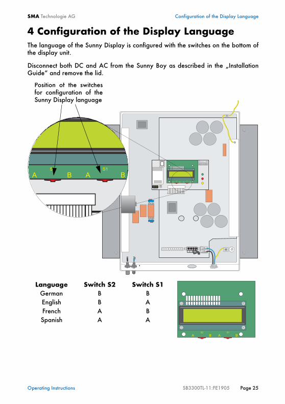
4 Configuration of the Display LanguageThe language of the Sunny Display is configured with the switches on the bottom ofthe display unit.
Disconnect both DC and AC from the Sunny Boy as described in the „InstallationGuide“ and remove the lid.
Language Switch S2 Switch S1German B BEnglish B AFrench A BSpanish A A
EN
S1
EN
S2
S15
S13
S11
S9
S7
S5
200V
150V
2 3 5 7
A
S2
AB B
S1
A
S2
AB B
S1
Position of the switchesfor configuration of theSunny Display language
A
S2
AB B
S1
A
S2
AB B
S1
Operating Instructions SB3300TL-11:FE1905 Page 25

Configuration of the Display Language SMA Technologie AG
Page 26 SB3300TL-11:FE1905 Operating Instructions

SMA Technologie AG Service and Maintenance
5 Service and MaintenanceIn order to be able to use the Sunny Boy 3300TL even outdoors at places hard toreach, the device was designed to ensure minimum maintenance. In order to ensuresafe operation it is normally sufficient to check the device approximately every twomonths for visible damages. Also check if the red LED is on.
To obtain optimum yield the plant operator should check the performance under dif-ferent irradiation conditions by controlling if the LEDs of the Sunny Boy 3300TL sig-nals plausible normal operation (see chapter 3.3.4 "Description of Operating States"(page 12)). Of course, this can also be checked with one of the optional communi-cation devices.
It is only necessary to clean the Sunny Boy if heat dissipation is disturbed by dirt par-ticles on the fins of the heatsinks or in the space between the inverter and the wall.Carefully remove the dirt with an appropriate soft brush.
If the status LEDs are dirty and no longer clearly visible, remove the dirt with a moistcloth. Solving agents, abrasives or corrosives may not be used for cleaning!
Operating Instructions SB3300TL-11:FE1905 Page 27

Service and Maintenance SMA Technologie AG
Page 28 SB3300TL-11:FE1905 Operating Instructions

SMA Technologie AG Plant Monitoring
6 Plant MonitoringYou can monitor your PV-plant with your Sunny Boy 3300TL in different ways. SMAoffers different products allowing you to install a customized plant monitoring. Pleaseorder the Sunny Family Catalog for detailed information of our Sunny Boy 3300TLproducts or visit our homepage at www.SMA.de. Our available communication op-tions ared described in the chapters below.
6.1 Sunny DataSunny Data is a PC program for monitoringyour PV-plant. The connection of your SunnyBoy or Sunny Mini Central is described in thefollowing chapters.
6.1.1 Sunny Data via Power Line„Wireless“ communication via power line(with up to 50 Sunny Boys or Sunny Mini Centrals)Requirements: The Sunny Boys and Sunny Mini Centrals have to be equipped withthe Powerline Kit and the PC with an SWR-COM socket modem. How to connect thePC via SWR-COM is described in the documentation of the SWR-COM.
max. 50
SWR-COMsocket connector
PC withSunny Data
ErdschlussEarth Fault
Art
.-N
r.: 8
6-0
0
ErdschlussEarth Fault
Art
.-N
r.: 8
6-0
0
ErdschlussEarth Fault
Art
.-N
r.: 8
6-0
0
Operating Instructions SB3300TL-11:FE1905 Page 29

Plant Monitoring SMA Technologie AG
6.1.2 Sunny Data via RS232Communication via cable(one single Sunny Boy or Sunny Mini Central)Requirements: The Sunny Boy or Sunny Mini Central has to be equipped with theRS232 Piggy-Back. The PC is connected directly to the COM1 or COM2 port of thePC. The installation of the RS232 cable is described in the Installation Guide of theSunny Boy 3300TL.
6.1.3 Sunny Data via RS485Communication via cable(with up to 50 Sunny Boys or Sunny Mini Centrals)Requirements: All Sunny Boys and Sunny Mini Centrals have to be equipped with anRS485 Piggy-Back. The PC is connected to the COM1 or COM2 power via anRS485/RS232 interface converter. The installation of the RS485 cable is describedin the Installation Guide of the Sunny Boy 3300TL.
PC withSunny Data
ErdschlussEarth Fault
Art
.-N
r.: 8
6-0
0
max. 50
PC withSunny Data
Interfaceconverter
(RS485/RS232)
RS232
RS485
ErdschlussEarth Fault
Art
.-N
r.: 8
6-0
0
ErdschlussEarth Fault
Art
.-N
r.: 8
6-0
0
ErdschlussEarth Fault
Art
.-N
r.: 8
6-0
0
Page 30 SB3300TL-11:FE1905 Operating Instructions

SMA Technologie AG Plant Monitoring
6.1.4 Sunny Data via Sunny BeamCommunication with a PC via Sunny Beam(with up to 4 Sunny Boys or Sunny Mini Centrals)Requirements: All Sunny Boys and Sunny Mini Centrals have to be equipped with aRadio Piggy-Back and to be detected by the Sunny Beam for plant monitoring. Usea USB cable for connecting the Sunny Beam with the PC. The installation of the RadioPiggy-Back and the connection to the PC is described in the „Operating Instructions“of the Sunny Beam.
6.2 Sunny BeamSimple plant monitoring via radio with up to 4 Sunny Boys or Sunny Mini Centrals.Requirements: The Sunny Boys and Sunny Mini Centrals have to be equipped with aRadio Piggy-Back and a Sunny Beam has to be positioned in appropriate distance.
6.3 Sunny Boy Control LightThe Sunny Boy Control Light is a basic data logger for PV-plants with up to 10 SunnyBoys or Sunny Mini Centrals. The data between the Sunny Boy Control Light and theSunny Boys and/or Sunny Mini Centrals is transmitted via power line.Requirements: Sunny Boys and Sunny Mini Centrals have to be equipped with thePowerline Kit. The installation is described in the documentation of the Sunny BoyControl Light.
max. 4
Sunny Beam PC withSunny Data
USBErdschlussEarth Fault
Art
.-N
r.: 8
6-0
0
ErdschlussEarth Fault
Art
.-N
r.: 8
6-0
0
ErdschlussEarth Fault
Art
.-N
r.: 8
6-0
0
max. 4
Sunny Beam
ErdschlussEarth Fault
Art
.-N
r.: 8
6-0
0
ErdschlussEarth Fault
Art
.-N
r.: 8
6-0
0
ErdschlussEarth Fault
Art
.-N
r.: 8
6-0
0
max. 10
Sunny BoyControlLight
Powerline
PAC 1273 W
ErdschlussEarth Fault
Art
.-N
r.: 8
6-0
0
ErdschlussEarth Fault
Art
.-N
r.: 8
6-0
0
ErdschlussEarth Fault
Art
.-N
r.: 8
6-0
0
Operating Instructions SB3300TL-11:FE1905 Page 31

Plant Monitoring SMA Technologie AG
6.4 Sunny Boy ControlThe Sunny Boy Control is a data logger for PV-plants with up to 50 Sunny Boys orSunny Mini Centrals. It is possible to connect the Sunny Boys and / or Sunny MiniCentrals as follows:
Powerline - „Wireless“ communication via power lineRequirements: All Sunny Boys and Sunny Mini Centrals have to be equipped with thePowerline Kit.
RS485 communication via cableRequirements: All Sunny Boys and Sunny Mini Centrals have to be equipped with anRS485 Piggy-Back. The Sunny Boy Control has to be equipped with an RS485 Piggy-Back at the interface „COM-1 Sunny Boy“.
6.5 Sunny Boy Control PlusThe Sunny Boy Control Plus is a data logger for PV-plants with up to 50 Sunny Boysor Sunny Mini Centrals. It has one additional interface for a PC or external displayand additional interfaces for digital and analog in- and outputs.
Requirements: See Sunny Boy Control
max. 50ErdschlussEarth Fault
Art
.-N
r.: 8
6-0
0
ErdschlussEarth Fault
Art
.-N
r.: 8
6-0
0
ErdschlussEarth Fault
Art
.-N
r.: 8
6-0
0
Sunny BoyControl
PAC 1273 W
max. 50
Sunny BoyControl
RS485
PAC 1273 W
ErdschlussEarth Fault
Art
.-N
r.: 8
6-0
0
ErdschlussEarth Fault
Art
.-N
r.: 8
6-0
0
ErdschlussEarth Fault
Art
.-N
r.: 8
6-0
0
Page 32 SB3300TL-11:FE1905 Operating Instructions

SMA Technologie AG Plant Monitoring
6.6 Sunny Data ControlSunny Data Control is a PC program for plant monitoring and visualization with thePC for plants with Sunny Boy Control.Requirements: PV-plant with Sunny Boy Control, Sunny Boy Control Plus or SunnyBoy Control Light with connection to a PC.
If required, the PC can also be connectedwith the Sunny Boy Control via modem. Byconnecting several Sunny Boy Controls, it ispossible to monitor large scale plants withmore than 50 Sunny Boys or Sunny MiniCentrals.
Sunny Boy 3300TL Internetpresentation
withSDC-Agent
...
Visualizationwith Sunny Data
Control
Connection alsopossible via Modem
Remote Desktop
...
Data evaluationwith Excel
Internetpresentation
withSMA-Portal
ErdschlussEarth Fault
Art
.-N
r.: 8
6-0
0
ErdschlussEarth Fault
Art
.-N
r.: 8
6-0
0
ErdschlussEarth Fault
Art
.-N
r.: 8
6-0
0
Operating Instructions SB3300TL-11:FE1905 Page 33

Plant Monitoring SMA Technologie AG
6.7 Sunny WebBoxSunny WebBox is a multifunctional and cost effective device for the plant monitoringdirectly on the PC or via internet with Sunny Portal. The Sunny WebBox will be avail-able at the 2nd quarter of 2005.
6.8 Sunny PortalSunny Portal is SMA’s powerful internet pre-sentation platform from SMA, which allowsyou to monitor and present your PV-plant inthe internet. For detailed information pleasesee the Sunny Family Catalog or www.SUNNY-PORTAL.de.
Sunny Boy 3300TL
...Sunny
WebBox
LAN
LAN
PC
PC viaModem
ExternalDisplay
ExternalSensors
ExternalDisplay
Memory Card
RS232RS485PowerlineRadio
SunnyPortal
(Internet)
LAN
LAN
Hub
TelephoneConnection
ErdschlussEarth Fault
Art
.-N
r.: 8
6-0
0
ErdschlussEarth Fault
Art
.-N
r.: 8
6-0
0
ErdschlussEarth Fault
Art
.-N
r.: 8
6-0
0
Page 34 SB3300TL-11:FE1905 Operating Instructions

SMA Technologie AG Plant Monitoring
6.9 Sunny TVSunny TV is an accessory kit for Sunny Boys and Sunny Mini Centrals which displaysthe plant data and current power on a display or video projector. You can use theSunny TV for presenting large-scale PV-plants in entrance areas and lobbies or forprivate purposes. Sunny TV is available at the 2nd quarter of 2005.
...
RS232RS485PowerlineRadio
Sunny TV
Configurationwith PC
Sunny TVPac = 7,450 W
Sunny TVPac = 7,450 W
Sunny TVPac = 7,450 W
Video Projector TV Set
Sunny TVPac = 7,450 W
PC Monitor
Video-Out
Sunny TV
Sunny TVPac = 7,450 W
Sunny Boy 3300TL
ErdschlussEarth Fault
Art
.-N
r.: 8
6-0
0
ErdschlussEarth Fault
Art
.-N
r.: 8
6-0
0
ErdschlussEarth Fault
Art
.-N
r.: 8
6-0
0
Operating Instructions SB3300TL-11:FE1905 Page 35

Plant Monitoring SMA Technologie AG
Page 36 SB3300TL-11:FE1905 Operating Instructions

SMA Technologie AG Technical Documentation
7 Technical Documentation
7.1 Data PV-Generator Connection
7.2 Data Grid Connection
Max. input open-circuit voltage UPV 0 750 V (at -10 °C module temperature)
Input voltage, MPP operation UPV 125 V ... 750 V DC
Max. input current IPV max 8 A
Max. input power PPV 3450 W
Recommended max. generator power
3850 W
All-pole disconnector on DC input side
snap cable connectors
Surge voltage protection thermally monitored varistors
Voltage ripple UPP < 10 % of input voltage
Personnel protection Ground Fault monitoring (Riso > 1 MΩ)
Internal consumption in operation < 10 W (stand-by)
Pole confusion prevention by short-circuit diode
Nominal output power PACnom 3000 VA
Peak output power PACmax 3300 W
Nominal output current IACnom 13 A
Harmonic distortion of output (with KUnom < 2 %, PAC > 0,5 PACnom)
THDIAC 4 %
Short-circuit resistance Imax = 30 A
Operating range, grid voltage UAC 198 ... 260 V AC
Operating range, grid frequency fAC 49.8 ... 50.2 Hz
All-pole disconnector on grid side independent disconnection device (MSD), (2 independent systems)
Phase difference (related to basic wave of current) cos ϕ 1
Overvoltage category III
Test voltage (50 Hz) 1.65 kV (5 s unit / type test)
Surge voltage test 4 kV (1.2/50 ms)(serial interface: 6 kV)
Internal consumption in stand-by 0.3 W
Operating Instructions SB3300TL-11:FE1905 Page 37

Technical Documentation SMA Technologie AG
7.3 Description of DeviceYou will find a detailed device description in chapter 3 "Device Description" (page7) of these Operating Instructions.
General Data
External interfaces
Efficiency
The efficiency of the Sunny Boy 3300TL depends on the DC input voltage from thePV-modules. The higher the voltage the higher is the efficiency of the Sunny Boy3300TL.
Protection degree (DIN EN 60529) IP65
Dimensions (width x height x depth) approx. 470 mm x 490 mm x 225 mm
Weight approx. 28 kg
Data transmission via Powerline optional
Data transmission via separate data cable optional, RS232 / RS485, electrically separated
Data transmission via radio optional
Max. efficiency at nominal voltage ηmax 95.6 %
European weighted efficiency ηeuro > 94.7 %
Sunny Boy 3300TL
0 500 1000 1500 2000 2500 3000
300 V
400 V520 V
Output Power [kW]
Tota
l Effi
cien
cy [%
]
Page 38 SB3300TL-11:FE1905 Operating Instructions

SMA Technologie AG Technical Documentation
7.4 Measurement Channels and Messages If your Sunny Boy 3300TL has been equipped with a communication interface, nu-merous measurement channels and messages can be acquired. These can help to im-prove the performance as well as eliminate failures of your plant.
BFR: System control SRR: Current control
7.4.1 Measurement ChannelsdI Residual currents between the modules and the Sunny Boy
E-Total Total power fed to the grid accumulated from the day of instal-lation
E-Total DC Total DC Yield
Fac Grid frequency
Fehler/Failure Display of failure type in „Failure“ state
Fehler-Cnt/Error-Cnt
Total number of errors
h-On Total sum of operating hours
h-Total Total sum of operating hours in feeding operation
Iac Current fed to the grid
Netz-Ein/Power ON
Total number of connections to the grid
Pac Current output power
Riso Insulation resistance of PV-plant before connection to the grid
Seriennummer/Serial Number
Serial number of the Sunny Boy
Status/Mode Display of current operating state
Uac/Vac Grid voltage
Upv-Ist /Vpv
PV-input voltage
Upv-Soll /Vconst-Setpoint
PV setpoint voltage
Zac Grid impedance
PPV DC-A Current power from String A
Operating Instructions SB3300TL-11:FE1905 Page 39

Technical Documentation SMA Technologie AG
7.4.2 Status MessagesThe Sunny Boy 3300TL generates a number of status messages according to themode it currently operates in. The status messages displayed can differ depending onthe type of communication you are currently using (Sunny Display, Sunny Data, Sun-ny Boy Control, Sunny Data Control).
Message DescriptionMPP The Sunny Boy 3300TL is operating in MPP mode. The input
voltage setpoint is permanently adjusted in order to obtain themaximum energy from the different strings. This is the defaultoperating mode in normal operation with normal irradiation.
U-Konst Constant voltage operation. (The input voltage from the PV-modules is fixed to a defined setpoint. The Sunny Boy 3300TLis not operating in MPP mode.) This mode can be defined asoperating mode in special applications.
I-Konst Constant current operation. (The input current from the PV-modules is specified to a defined setpoint. The Sunny Boy3300TL is not operating in MPP mode.) This mode can be de-fined as operating mode in special applications.
Derating PV-generator power is higher than the amount the Sunny Boy3300TL can process.
Derating Idc /derat. Idc
The Sunny Boy 3300TL is reducing the output power due toovercurrent on the DC side. This is not a critical status, but yourplant is loosing energy in this mode. Have your installer checkthe configuration of your plant if this occurs regularly.
Derating WR (T°)Derating DC (T°)
The Sunny Boy 3300TL is reducing the output power due toovertemperature of the DC converters („DC“) or the inverterbridge („WR“). Have your configuration and your string sizechecked if this occurs regularly. Ventilation and sufficientclearance can solve this problem.
Fehler/Error
A failure has been detected and a failure message has beengenerated (see following table „Failure messages“).
Netzueb. /grid. mon.
Test of grid status for subsequent connection (grid imped-ance), relay test etc. This mode only occurs during startup, be-fore the Sunny Boy connects to the grid. This status can oftenoccur during the morning and evening with varying irradia-tion.
Offset Offset adjustment of measurement electronics
Riso Measurement of irradiation resistance of PV-plant
Stoer./disturb. Failure (see following table „Failure messages“)
Page 40 SB3300TL-11:FE1905 Operating Instructions
SMA Technologie AG Technical Documentation
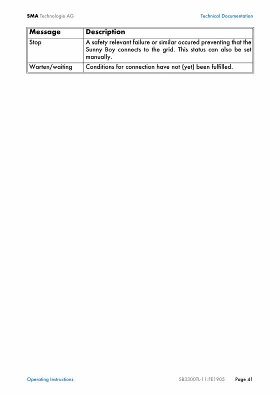
Stop A safety relevant failure or similar occured preventing that theSunny Boy connects to the grid. This status can also be setmanually.
Warten/waiting Conditions for connection have not (yet) been fulfilled.
Message Description
Operating Instructions SB3300TL-11:FE1905 Page 41
Technical Documentation SMA Technologie AG
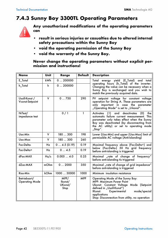
7.4.3 Sunny Boy 3300TL Operating Parameters
Any unauthorized modifications of the operating parameterscan
• result in serious injuries or casualties due to altered internalsafety precautions within the Sunny Boy
• void the operating permission of the Sunny Boy• void the warranty of the Sunny Boy.
Never change the operating parameters without explicit per-mission and instructions!
Name Unit Range Default Description
E_Total kWh 0 ... 200000 Total energy yield (E_Total) and totaloperating hours (h_Total) of the inverter.Changing the value can be necessary when aSunny Boy is exchanged and you wish tomatch the previously acquired data.
h_Total h 0 ... 200000
Usoll-Konst /Vconst-Setpoint
V 0 ... 750 290 PV setpoint voltage for constant voltageoperation for String A. These parameters areonly important in case the parameter„Operating Mode“ is set to „U-konst“.
NiTest/impedance test
0 / 1 1 Activates (1) and deactivates (0) theautomatic failure current measurement. Thisparameter only takes effect when the SunnyBoy was deactivated (by disconnecting fromthe AC utility) or set to operating mode„Stop“.
Uac-Min V 180 ... 300 198 Lower (Uac-Min) and upper (Uac-Max) limit ofpermissible AC voltage (Anti-Islanding)
Uac-Max V 180 ... 300 260
Fac-Delta- Hz 0 ... 4.5 (0.19) 0.19 Maximal frequency above (Fac-Delta+) andbelow (Fac-Delta-) 50 Hz grid frequencybefore anti-islanding is triggeredFac-Delta+ Hz 0 ... 4.5 0.19
dFac-MAX Hz/s 0.005 ... 4.0 0.25 Maximal „rate of change of frequency“before anti-islanding tis triggered
dZac-MAX mOhm 0 ... 2000 350 Maximal „rate of change of grid impedance“before anti-islanding is triggered
Riso-Min kOhm 1000 ... 30000 1000 Minimum insulation resistance
Betriebsart/Operating Mode
MPP/Ikonst/
UKonst/Stop
MPP Operating Mode of the Sunny Boy: MPP: Maximum Power PointUkonst: Constant Voltage Mode (Setpointdefined in „Usoll-Konst“)IKonst: Experimental mode/specialapplications Stop: Disconnection from utility, no operation
Page 42 SB3300TL-11:FE1905 Operating Instructions

SMA Technologie AG Technical Documentation
The following parameters appear in the parameter list but cannot be modified:
SpeicherfunktionMemory Function
Default parameter/
Reset Operating
Data/Reset Failure
none Default parameter: Sets all parameters todefault.Reset Operating Data: Sets all parametersvisible in user level to default values.Reset Failure: Resets all permanent devicefailure (dBh)
Default GER/ENS
Used for adjusting the country specific settings
Storage permanent/volatile
perma-nent
permanent: changed parameters are stored inEEPROM and are still available afterrestarting the Sunny Boysvolatile: prevents storing the parameters inEEPROM,i. e. parameters are only saved until nextstartup
Inst.-Code The parameters concerning anti-islanding canonly be changed after entering the installerspassword here.
Name Unit Range Default Description
Plimit W 3300 Upper limit of AC output power
SMA-SN Serial Number of the Sunny Boy
Software-BFR Firmware version of the operation control unit(BFR)
Software-SRR Firmware version of the current control unit(SRR)
Hardware-DC-BFR
Hardware version of the DC converter control unit (DC-BFR)
Firmware-DC-BFR Firmware version of the DC converter control unit (DC-BFR)
Name Unit Range Default Description
Operating Instructions SB3300TL-11:FE1905 Page 43

Technical Documentation SMA Technologie AG
7.4.4 Precision of Measured Value AcquisitionAcquisition of measured values is always more or less imprecise. The measued valuesacquired by the Sunny Boy 3300TL are required for its system management and con-trol of current to be fed into the grid. This is why measured values of the Sunny Boy3300TL must be reproducible. The maximum error of measured value acquisition isspecified for an ambient temperature TU of 25°C. A temperature coefficient failuremust be accounted for with other ambient temperatures.
Physicalvariable
Unit Measurementrange
Resolu-tion of display
Resolution of measure-
ment
Max. failure (of final value,
TU=25°C)
Input voltage UPV [V] 0 ... 800 V 1 V 0.78 V ±2 %
Input current IPV [mA] 0 ... 10000 mA 1 mA 9.8 mA ±2 %
Grid voltage UAC [V] 180 ... 278 Veff 1 V 0.27 Veff ±1 %
Grid current IAC [mA] 0 ... 26.5 Aeff 1 mA 13 mAeff ±2 %
Grid frequency fAC [Hz] 45 ... 55 Hz 0.01 Hz 0.01 Hz ±0.1 %
Current powerfed to grid
PAC [W] 0 ... 7367 W 1 W 1 W ±3 %
Total energy fedto grid
E [kWh] 0 ... 4.29*109Wmin 1 Wmin 20 Wmin ±3 %
Operating hours h [h] 0 ... 4.299*109 s 1 s 375 ns ±0.1 %
Page 44 SB3300TL-11:FE1905 Operating Instructions

SMA Technologie AG Technical Documentation
7.4.5 Failure MessagesIn case of a failure the Sunny Boy 3300TL generates the failure code according tothe operating mode and the detected failure.
Failure Code Descripition
CANKom DC-BFSDC-BFS-Startup
Internal communication failure. Contact SMA in case you observethis failure very often.
DCBFS Version The DC-BFS has a wrong firmware. Contact SMA in case you ob-serve this failure.
Delta Bfr-SrrNUW-dINUW-FACNUW-UACNUW-ZACNUW-Timeout
Internal measurement comparison error: The Sunny Boy 3300TLmeasured values of BFR and SRR are too different from each other.
dFac-BfrdFac-Srr
The rate of change of the AC grid frequency is exceeding the per-missible range („Bfr“ or „Srr“ is an internal message and is not im-portant for the user). The Sunny Boy assumes that the public grid isdown and disconnects from the grid in order to avoid islanding.
Check the grid frequency and the rate of fluctuation. If the grid fre-quency fluctuates often and thus „dFac-Bfr“ or „dFac-Srr“ failuresoften occur consult the utility company if it is permissable to changethe grid monitoring parameters of the Sunny Boy. Contact SMAabout how to change the grid monitoring parameters of your SunnyBoy.
dI-Bfr dI-Srr
The Sunny Boy 3300TL has detected a drastic change of the dis-charge current. As the Sunny Boy 3300TL is a transformerless in-verter there is no electric separation. A sophisticated and effectivedischarge current monitoring is an important element of the person-nel protection.
A drastic change of the discharge current can be the result of a mal-function or a sudden dangerous ground fault. The Sunny Boy dis-connects all poles (DC and AC). Have a qualified technician checkthe isolation and the ground connection in case the message „dI-Bfr“ or „dI-Srr“ is displayed without any obvious cause in your sys-tem.
dI-Mess Defective acquisition of differential current / fault current - the Sun-ny Boy is deactivated for the rest of the day and will return to nor-mal operation on the next day. A restart will reset the Sunny Boy tonormal operation as well.
Operating Instructions SB3300TL-11:FE1905 Page 45

Technical Documentation SMA Technologie AG
dI-Test Failure of differential current converter
dZac-BfrdZac-Srr
The rate of change of the AC grid impedance is exceeding the per-missible range („Bfr“ or „Srr“ is an internal message and is not im-portant for the user). The Sunny Boy assumes that the public grid isdown and disconnects from the grid in order to avoid islanding.Check the grid impedance and the rate of fluctuation. If the grid fre-quency fluctuates often and thus „dZac-Bfr“ or „dZac-Srr“ failuresoften occur consult the utility company if it is permissible to changethe grid monitoring parameters of the Sunny Boy. Contact SMAabout how to change the grid monitoring parameters of your SunnyBoy.
EEPROM Transition failure during reading or writing of data EEPROM, thedata is not essential for safe operation - this failure does not effectperformance.
EEPROM dBh Data EEPROM defective, device is set to permanent disable due tothe fact that the data loss affects important functions of the SunnyBoy. Contact SMA.
EeRestore A data record was defective and was reconstructed.
Fac-BfrFac-Srr
The AC grid frequency is exceeding the permissible range („Bfr“ or„Srr“ is an internal message and is not important for the user). TheSunny Boy 3300TL assumes that the public grid is down and discon-nects from the grid in order to avoid islanding. Check the grid frequency and the grid cable connection in the Sun-ny Boy enclosure. If the grid frequency is out of range due to yourlocal grid conditions consult the utility company if it is permissible tochange the grid monitoring parameters of the Sunny Boy. ContactSMA about how to change the grid monitoring parameters of yourSunny Boy. If the grid frequency is within the tolerable range and the failuremessage „Fac-Bfr“ or „Fac-Srr“ is still displayed, contact SMA.
IGBTs The internal hardware monitoring has detected a defect of an in-verter part. Contact SMA in case this failure often occurs.
Imax Overcurrent on the AC side. This failure code is indicated in casethe current to the AC grid exceeds the specification. Have yourplant configuration checked.
Imax DC Overcurrent in the intermediate DC circuit of the Sunny Boy3300TL. The Sunny Boy is detecting a current exceeding the speci-fications within its intermediate circuit. This is the result of a too highcurrent on the DC input. Have your plant configuration checked.
Failure Code Descripition
Page 46 SB3300TL-11:FE1905 Operating Instructions

SMA Technologie AG Technical Documentation
L<->N L and N mixed up on AC connection. Have an installer check instal-lation.
Offset Grid monitoring self-test failed.
Rechner Failure in operation of one of the two microcontrollers
Relais1Relais2Relais3Relais4L-Netz/N-WR/ N-Netz
Grid connection relay self test failed. The Sunny Boy checks the re-lays that connect the Sunny Boy to the grid before it starts feedingto the grid. In case the grid relays do not function correctly the safeand reliable disconnection cannot be guaranteed and the SunnyBoy does not connect to the grid. Contact SMA in case this failureoften occurs.
Riso The PV-system is not electrically separated from ground. The resis-tance between one of the poles and ground is below a definedthreshold.
Shutdown Serious failure, device shut down until next switch-on.
ROM The internal test of the Sunny Boy control system firmware failed.Contact SMA in case this failure occurs often.
Uac-Bfr/Uac-Srr
The AC grid voltage is exceeding the permissible range („Bfr“ or„Srr“ is an internal message and is not important for the user). Uaccan result from:• a disconnected grid (circuit breaker, fuse)• a disconnected AC cable• high-resistant AC cable
The Sunny Boy 3300TL assumes that the public grid is down and dis-connects from the grid in order to avoid islanding. Check the gridvoltage and the grid cable connection in the Sunny Boy enclosure.If the grid voltage is out of range due to your local grid conditionsconsult the utility company if it is possible to modify the utility con-ditions.
If the grid voltage is within the tolerable range and the failure mes-sage „Uac-Bfr“ or „Uac-Srr“ is still displayed, contact SMA.
UDiffUzkposneg<10
Defective DC link. Contact SMA in case you observe this failure of-ten.
Failure Code Descripition
Operating Instructions SB3300TL-11:FE1905 Page 47

Technical Documentation SMA Technologie AG
Uzwk Overvoltage on the DC input.
Disconnect the Sunny Boy from the PV-modules immediately! TheSunny Boy can be severly damaged!
Have your plant configuration checked before you reconnect theDC voltage.
WatchdogWatchdog Srr
Internal Watchdog function triggered.
Zac-Bfr/Zac-Srr
The AC grid impedance is exceeding the permissible range („Bfr“or „Srr“ is an internal message and is not important for the user).The Sunny Boy assumes that the public grid is down and disconnectsfrom the grid in order to avoid islanding.
The impedance is the sum of the grid’s internal impedance and theimpedance of the AC cable that connects the Sunny Boy to the grid.
Check the grid impedance and the grid cable connection in the Sun-ny Boy enclosure. Use a cable with a higher cross section (=lowerimpedance) for connecting the Sunny Boy to the grid. If the grid im-pedance is out of range due to your local grid conditions consultthe utility company if it is possible to modify the utility conditions.
Failure Code Descripition
Page 48 SB3300TL-11:FE1905 Operating Instructions

SMA Technologie AG Technical Documentation
7.5 Declaration of Conformity (CE)
SB-K
16A
-CE-
12:B
E030
5
SMA Technologie AGHannoversche Strasse 1-5 34266 NiestetalTel. +49 561 9522 – 0Fax +49 561 9522 – [email protected]
CE Declaration of Conformityfor utility interactive inverters
Produkt: Sunny BoyTyp: SB 700, SB 1100, SB 1700, SB 2100TL, SB 2500, SB 2800i, SB 3000,
SB 3300TL
We declare that the above specified devices are compliant with the regulations of the EuropeanCommunity, in terms of the design and the version fabricated by SMA. This especially applies forthe EMC Regulation defined in 89/336/EWG and the low voltage regulation defined in73/23/EWG.
The devices are compliant with the following standards:
EMC:Emission: DIN EN 61000-6-3: 2002-08
DIN EN 61000-6-4: 2002-08DIN EN 55022: 2003-09, class B
Utility Interference: DIN EN 61000-3-3: 2002-05DIN EN 61000-3-2: 2001-12
Immunity: DIN EN 61000-6-1: 2002-08DIN EN 61000-6-2: 2002-08
Safety: DIN EN 50178: 1998-04Semiconductor-Converter: DIN EN 60146-1-1: 1994-03
The above mentioned devices are therefore marked with a CE sign.Niestetal, 19th of January 2005
SMA Technologie AG
i.V. Frank Greizer(Head of Development Department Solar Technology)
Operating Instructions SB3300TL-11:FE1905 Page 49

Technical Documentation SMA Technologie AG
7.6 Clean Report of Findings (Grid Guard)The Sunny Boy 3300TL is equipped with the automatic anti-islanding unit „SMA gridguard“. The following „clean report of findings“ applies for this unit.
Page 50 SB3300TL-11:FE1905 Operating Instructions

SMA Technologie AG Glossary
8 GlossaryACAbbreviation for „Alternating Current“
Central inverterInverter concept where all PV-modules are wired among each other (switching in se-ries and/or in parallel). One single inverter feeds into the external grid. Costs for acentral inverter concept are lower, but installation might be much more complicatedand yield losses may occur due to shadowing of individual solar modules.
DCAbbreviation for „Direct Current“
DeratingControlled reduction of power, mostly depending on temperatures of certain mod-ules. Compared to a complete shutdown of a device, which is a usual procedure aswell, the negative impact on the external grid is lower with derating.
Grid-tied plantPV-plant connected to a public electricity grid run by an external supplier company.
InverterDevice to convert the direct current (DC) supplied by the PV-generator into alternat-ing current (AC) which is required for the supply of most consumers and especiallyfor feeding into the public grid. Inverters for PV-plants usually include one or moreMPP trackers.
Maximum Power Point „MPP“The operating point (current / voltage) of the PV-generator where this generatesmaximum power under the current conditions. The position of the MPP changes con-tinuously, e. g. depending on irradiation and temperature.
MPP trackerUnit that adjusts current and voltage of the PV-generator in a way as to make the gen-erator operate in its maximum power point.
MSDThe „Mains monitoring with allocated Switching Devices“ is an obligatory safety de-vice which interrupts the inverter’s feeding of PV-power to the grid if the externalpower generators have shut down.
Operating Instructions SB3300TL-11:FE1905 Page 51

Glossary SMA Technologie AG
Multi-String inverterInverter which combines the advantages of using several string inverters (separateMPP tracking of individual strings) with those using one central inverter (low power-specific costs).
PLCAbbreviation for „Power Line Communication“, term for data transmission via thegrid cable
PVAbbreviation for „Photovoltaics“, term for the conversion of light energy into electri-cal energy.
PV-generatorTechnical facility to convert light energy into electrical energy. Usually the term in-cludes all PV-modules of a PV-plant that have been mounted and electrically wired.
PV-moduleSee „Solar module“
PV-plantA system consisting of components required for the generation and utilization of so-lar energy. In the case of grid-tied plants these components include the PV-generatorand the inverter.
Solar cellElectronic component which can supply electrical energy when in sunlight. As theelectric voltage of one single solar cell is very low (approx. 0.5 V) several cells arecombined into solar modules. The material mostly used for solar cells at the momentis silicon. It is upgraded in different ways (mono-crystaline, poly-crystaline, amorph)before use. There are also various ways to increase efficiency mechanically. In addi-tion totally new materials are currently tested (Cadmium-Tellurid, Cadmium-Indium-sulfide, titan dioxide etc.).
Solar energyEnergy supplied by the sun, i. e. energy from sunlight or other irradiation (heat, UVradiation)
Solar moduleCombination of individual solar cells in one enclosure which protects the delicate cellsagainst mechanical strain and guarantees easy installation.
Stand-alone plant, island plantPower supply system which is totally independent from external power supply.
Page 52 SB3300TL-11:FE1905 Operating Instructions

SMA Technologie AG Glossary
StringA group of solar modules switched in series. Usually a PV-plant consists of severalstrings. Thus it is possible to avoid too high yield losses if the modules are shadowedto a different extent.
String inverterInverter concept avoiding the disadvantages of a concept with one central inverter.The PV-generator is divided into individual strings which are each connected to theexternal grid with their own string inverter. This considerably simplifies installationand reduces yield losses due to variations in manufacturing or a different degree ofshading of solar modules.
Operating Instructions SB3300TL-11:FE1905 Page 53

Glossary SMA Technologie AG
Page 54 SB3300TL-11:FE1905 Operating Instructions

SMA Technologie AG Contact
9 ContactIf you have any questions or technical problems concerning the Sunny Boy 3300TLour hotline will be happy to assist you. Please hold the following data ready whencontacting SMA:• Type of inverter• Type of modules connected and number of modules• Communication interfaces• Serial number of the Sunny Boy
Address:
SMA Technologie AGHannoversche Strasse 1 - 534266 NiestetalGermany
Tel.:+49 (561) 95 22 - 499 Fax:+49 (561) 95 22 - [email protected]
Operating Instructions SB3300TL-11:FE1905 Page 55
Contact SMA Technologie AG
Page 56 SB3300TL-11:FE1905 Operating Instructions


SMA Technologie AG
www.SMA.deSMATechnologie AG
Hannoversche Straße 1–534266 NiestetalGermanyTel. +49 561 9522 - 0Fax +49 561 9522 - 100www.SMA.de
SMA America, Inc.12438 Loma Rica Drive, Unit CGrass Valley, CA 95945USATel. +1 530 273 4895Fax +1 530 2747 271www.SMA-AMERICA.com
SMA Solartechnology ChinaRoom 20F, InternationalMetro Center,Building A, City Square No. Jia 3,Shilipu Road, Changyang District100025 Beijing, PR. ChinaTel. +86 10 65 58 78 15Fax +86 10 65 58 78 13www.SMA-CHINA.com
Seite 58 SB3300TL-11:FE1705 Operating Instructions