Embed Size (px)
Citation preview

SUN2000 8–28KTL
MODBUS Interface Definitions
Issue 01
Date 2015-04-07
HUAWEI TECHNOLOGIES CO., LTD.

Issue 01 (2015-04-07) Huawei Proprietary and Confidential
Copyright © Huawei Technologies Co., Ltd.
i
Copyright © Huawei Technologies Co., Ltd. 2015. All rights reserved.
No part of this document may be reproduced or transmitted in any form or by any means without prior
written consent of Huawei Technologies Co., Ltd.
Trademarks and Permissions
and other Huawei trademarks are trademarks of Huawei Technologies Co., Ltd.
All other trademarks and trade names mentioned in this document are the property of their respective
holders.
Notice
The purchased products, services and features are stipulated by the contract made between Huawei and
the customer. All or part of the products, services and features described in this document may not be
within the purchase scope or the usage scope. Unless otherwise specified in the contract, all statements,
information, and recommendations in this document are provided "AS IS" without warranties, guarantees or
representations of any kind, either express or implied.
The information in this document is subject to change without notice. Every effort has been made in the
preparation of this document to ensure accuracy of the contents, but all statements, information, and
recommendations in this document do not constitute a warranty of any kind, express or implied.
Huawei Technologies Co., Ltd.
Address: Huawei Industrial Base
Bantian, Longgang
Shenzhen 518129
People's Republic of China
Website: http://www.huawei.com
Email: [email protected]

SUN2000 8–28KTL
MODBUS Interface Definitions About This Document
Issue 01 (2015-04-07) Huawei Proprietary and Confidential
Copyright © Huawei Technologies Co., Ltd.
ii
About This Document
Change History
Date Revision Version Change Description
2015-04-07 1.0 Initial draft completed.

SUN2000 8–28KTL
MODBUS Interface Definitions Contents
Issue 01 (2015-04-07) Huawei Proprietary and Confidential
Copyright © Huawei Technologies Co., Ltd.
iii
Contents
About This Document .................................................................................................................... ii
1 Introduction.................................................................................................................................... 1
1.1 Terms and Abbreviations .................................................................................................................................. 1
1.2 System Requirements ....................................................................................................................................... 2
2 Register Definitions ..................................................................................................................... 3
2.1 Configuration Parameters ................................................................................................................................. 3
2.2 System Commands ........................................................................................................................................... 6
2.3 Device Characteristics Information .................................................................................................................. 7
2.4 Real-time Sampling Information ...................................................................................................................... 8
2.5 Alarms .............................................................................................................................................................. 9
3 Communications Protocol Overview ...................................................................................... 17
3.1 Physical Layer ................................................................................................................................................ 17
3.2 Data Link Layer ............................................................................................................................................. 17
3.2.1 Addressing Mode .................................................................................................................................. 17
3.2.2 Frame Structure ..................................................................................................................................... 18
3.2.3 Data Encoding ....................................................................................................................................... 18
3.2.4 Interaction Process ................................................................................................................................ 18
3.2.5 CRC Checking ...................................................................................................................................... 18
3.3 Application Layer ........................................................................................................................................... 21
3.3.1 Function Code List ................................................................................................................................ 21
3.3.2 Exception Code List .............................................................................................................................. 21
3.3.3 Reading Registers (0X03) ..................................................................................................................... 22
3.3.4 Writing a Single Register (0X06) .......................................................................................................... 24
3.3.5 Writing Multiple Registers (0X10) ....................................................................................................... 25
3.3.6 Reading Device Identifiers (0X2B) ...................................................................................................... 26

SUN2000 8–28KTL
MODBUS Interface Definitions 1 Introduction
Issue 01 (2015-04-07) Huawei Proprietary and Confidential
Copyright © Huawei Technologies Co., Ltd.
1
1 Introduction
The ModBus-RTU protocol is a widely used industrial communications protocol. It is a
common language for electrical communications terminals, and has become an industrial
standard which enables inverters from different manufacturers to be networked and centrally
monitored. By using this protocol, inverters can communicate with each other or with other
devices in a network, such as through the RS485 bus. The protocol defines master and slave
nodes, the processes in which the master node accesses other devices using various requests,
how a slave node responds to requests from other devices, and how both parties involved in a
communications process detect and record errors. It also specifies the message field formats
and detailed data content.
As the Huawei inverter business continues to expand, more and more general and customized
inverters use the ModBus protocol for communication. This document provides information
about the ModBus protocol used in Huawei inverters, and can be used to regulate and restrict
follow-up third-party integration R&D and customizations.
1.1 Terms and Abbreviations
Name Description
Master node During master-slave communication, the party that initiates a
communication request is referred to as the master node.
Slave node During master-slave communication, the party that responds to a
communication request is referred to as the slave node.
Broadcast address Fixed to 0.
Register address The address of a register is recorded in two bytes.
U16 Unsigned integer (16 bits)
U32 Unsigned integer (32 bits)
I16 Signed integer (16 bits)
I32 Signed integer (32 bits)
MLD Multiple bytes
N/A Not applicable

SUN2000 8–28KTL
MODBUS Interface Definitions 1 Introduction
Issue 01 (2015-04-07) Huawei Proprietary and Confidential
Copyright © Huawei Technologies Co., Ltd.
2
1.2 System Requirements
Applicable model: SUN2000 8–28KTL
Firmware version: V100R001C11SPC409 or later

SUN2000 8–28KTL
MODBUS Interface Definitions 2 Register Definitions
Issue 01 (2015-04-07) Huawei Proprietary and Confidential
Copyright © Huawei Technologies Co., Ltd.
3
2 Register Definitions
2.1 Configuration Parameters
Configuration parameters involve permanent signals, and the data will be effective until
updated the next time. All the signals are RW signals and support 0X03, 0X06, and 0X10
commands.
SN Signal Name Type Unit Gain Address Quantity Range
1 Date and time
synchronization U32 N/A 1 40000 2 0–3155759999
2 Grid code U16 N/A 1 40002 1 0–23
3 MPPT setting U16 N/A 1 40004 1 0: Disable
1: Enable
4 Level-1 UF prot. U16 Hz 100 40006 1 85%–100%Fn
5 Level-1 UF prot. time U32 ms 1 40007 2 50–600000
6 Level-2 UF prot. U16 Hz 100 40009 1 85%–100%Fn
7 Level-2 UF prot. time U32 ms 1 40010 2 50–600000
8 10-min OV protec. U16 V 100 40012 1 100%–140%Vn
9 10-min OV protec. time U32 ms 1 40013 2 50–600000
10 MPPT scanning interval U16 min 1 40015 1 5–30
11 Insulation res. protec. U16 MΩ 1000 40022 1 0.033–1
12 Unbal. volt. protec. U16 % 10 40023 1 0–50
13
Reactive power
compensation (cosψ-P)
trigger voltage
U16 % 1 40032 1 100–110
14
Reactive power
compensation (cosψ-P) exit
voltage
U16 % 1 40033 1 90–100
15 Overfrequency deration
trigger threshold U16 Hz 100 40034 1 50–52
16 Overfrequency deration exit
threshold U16 Hz 100 40035 1 49.9–51
17 Overfrequency deration
recovery gradient U16 %/min 1 40036 1 5–20
18 Q-U characteristic curve
mode U16 N/A 1 40037 1 0–1

SUN2000 8–28KTL
MODBUS Interface Definitions 2 Register Definitions
Issue 01 (2015-04-07) Huawei Proprietary and Confidential
Copyright © Huawei Technologies Co., Ltd.
4
19 Q-U dispatch trigger power
percent U16 % 1 40038 1 10–100
20 Soft startup time after grid
failure U16 Sec 1 40041 1 20–800
21 LVRT U16 N/A 1 40051 1 00: Disable
01: Enable
22 Enable islanding detection
setting U16 N/A 1 40052 1
00: Disable
01: Enable
23 Soft start time U16 Sec 1 40053 1 20–800
24 Feed grid recovery time U16 Sec 1 40076 1 10–600
25 Level-1 OV prot. U16 V 100 40054 1 100%–140%Vn
26 Level-1 OV prot. time U32 ms 1 40055 2 50–600000
27 Level-2 OV prot. U16 V 100 40057 1 100%–140%Vn
28 Level-2 OV prot. time U32 ms 1 40058 2 50–600000
29 Level-1 UV prot. U16 V 100 40060 1 10%–100%Vn
30 Level-1 UV prot. time U32 ms 1 40061 2 50–600000
31 Level-2 UV prot. U16 V 100 40063 1 10%–100%Vn
32 Level-2 UV prot. time U32 ms 1 40064 2 50–600000
33 Level-1 OF prot. U16 Hz 100 40066 1 100%–115%Fn
34 Level-2 OF prot. time U32 ms 1 40067 2 50–600000
35 Level-2 OF prot. U16 Hz 100 40069 1 100%–115%Fn
36 Level-2 OF prot. time U32 ms 1 40070 2 50–600000
37 Reactive power
compensation U16 N/A 1 40117 1
0: Disable reactive
power output
1: Communication
adjustment power
factor
2: Parameter
setting Q/S
3: Parameter
setting power
factor
4: Q(u)
characteristic
curve
5: Power factor
characteristic
curve
38 Active power control U16 N/A 1 40118 1
0: Disable active
power limiting
1: Communication
limit percentage
(%)
2: Parameter
setting absolute
value kW
3: Parameter
setting percentage
39 Active power deration
setting [percentage] U16 % 1 40119 1 0–100
40 Active power deration U16 kW 10 40120 1 0–22

SUN2000 8–28KTL
MODBUS Interface Definitions 2 Register Definitions
Issue 01 (2015-04-07) Huawei Proprietary and Confidential
Copyright © Huawei Technologies Co., Ltd.
5
setting [fixed value]
41 Active power deration
gradient U16 %/s 10 40121 1 0.5–10
42
Reactive power
compensation setting [power
factor]
I16 N/A 1000 40122 1 0 <= |a| <= 1
43 Reactive power
compensation setting [Q/S] I16 N/A 1000 40123 1 –1 to 1
44 Reactive power adjustment
time U16 Sec 1 40124 1 5–120

SUN2000 8–28KTL
MODBUS Interface Definitions 2 Register Definitions
Issue 01 (2015-04-07) Huawei Proprietary and Confidential
Copyright © Huawei Technologies Co., Ltd.
6
2.2 System Commands
System command signals are WO signals. They do not support the 0X03 query command, but
supports the 0X06 and 0X10 commands.
SN Signal Name Type Unit Gain Address Quantity Range
1 Power on NULL N/A 40200 1 0
2 Power off NULL N/A 40201 1 0
3 Active power deration
percent U16 % 1 40234 1 0–100
4
Reactive power
compensation factor
instruction
I16 N/A 1000 40237 1 –1 to 1

SUN2000 8–28KTL
MODBUS Interface Definitions 2 Register Definitions
Issue 01 (2015-04-07) Huawei Proprietary and Confidential
Copyright © Huawei Technologies Co., Ltd.
7
2.3 Device Characteristics Information
Device characteristics information involves RO signals. They support only the 0X03
command but not the 0X06 or 0X10 command. This type of signal carries static inverter
configuration information, which remains unchanged if there is no firmware update.
Mapping Between Inverter Models and Rated Power
SN Model Pmax Qmax (kVar) Rated Power (kW)
0 20KTL 22 13.2 20
1 17KTL 18.7 11.22 17
2 15KTL 16.5 9.9 15
3 12KTL 13.2 7.92 12
4 10KTL 11 6.6 10
5 8KTL 8.8 5.28 8
9 500KTL 600 300 500
16 24.5KTL 24.5 14.7 24.5
17 23KTL 23 13.8 23
18 28KTL 27.5 16.5 27.5
19 33KTL 33 19.8 30
20 40KTL 40 24 36
SN Signal Name Type Unit Gain Address Quantity Range
1 Rated inverter power U16 N/A 1 40710 1
2 ESN MLD N/A 1 40713 10
3 Hardware version MLD N/A 1 40789 15
4 Software version MLD N/A 1 40819 15
5 ModBus protocol version MLD N/A 1 40834 15

SUN2000 8–28KTL
MODBUS Interface Definitions 2 Register Definitions
Issue 01 (2015-04-07) Huawei Proprietary and Confidential
Copyright © Huawei Technologies Co., Ltd.
8
2.4 Real-time Sampling Information
Real-time sampling information involves RO signals. They support only the 0X03
command but not the 0X06 or 0X10 command. This type of signal carries dynamic
update information, which reflects the inverter running status in real time.
SN Signal Name Type Unit Gain Address Quantity Remarks
1 PV1 Voltage/PV1 V I16 V 10 40500 1 For all power classes
2 PV2 Voltage/PV2 V I16 V 10 40501 1 For all power classes
3 PV3 Voltage/PV3 V I16 V 10 40502 1 For all power classes
4 PV4 Voltage/PV4 V I16 V 10 40503 1 For all power classes
5 PV5 Voltage/PV5 V I16 V 10 40504 1 For all power classes
6 PV6 Voltage/PV6 V I16 V 10 40505 1 For all power classes
7 PV1 Current/PV1 I I16 A 100 40506 1 For all power classes
8 PV2 Current/PV2 I I16 A 100 40507 1 For all power classes
9 PV3 Current/PV3 I I16 A 100 40508 1 For all power classes
10 PV4 Current/PV4 I I16 A 100 40509 1 For all power classes
11 PV5 Current/PV5 I I16 A 100 40510 1 For all power classes
12 PV6 Current/PV6 I I16 A 100 40511 1 For all power classes
13 CO2 reduction U32 kg 100 40523 2
14 Active power I32 kW 1000 40525 2
15 Uab U16 V 100 40527 1
16 Ubc U16 V 100 40528 1
17 Uca U16 V 100 40529 1
18 Power factor I16 N/A 1000 40532 1
19 Cabinet temperature I16 ℃ 10 40533 1
20 Reactive output power I32 kVar 1000 40544 2
21 Frequency U16 Hz 100 40546 1
22 E-Total U32 kWh 100 40560 2
23 Current-day yield U32 kWh 100 40562 2
24 Ia I16 A 100 40572 1
25 Ib I16 A 100 40573 1
26 Ic I16 A 100 40574 1
27 Inverter start time U32 Sec 1 40613 2
28 Inverter shutdown time U32 Sec 1 40615 2
29 Inverter efficiency U16 % 100 40685 1
30 MPPT1 total input power U32 kW 1000 40686 2
31 MPPT2 total input power U32 kW 1000 40688 2
32 MPPT3 total input power U32 kW 1000 40690 2
33 Total input power U32 kW 1000 40692 2
34 Zero voltage ride through
protection U16 N/A 1 40696 1
0: no
1: yes
35 LVRT protection U16 N/A 1 40697 1 0: no
1: yes
36 Anti-islanding U16 N/A 1 40698 1 0: no
1: yes
37 Locking U16 N/A 1 40699 1 0: lock

SUN2000 8–28KTL
MODBUS Interface Definitions 2 Register Definitions
Issue 01 (2015-04-07) Huawei Proprietary and Confidential
Copyright © Huawei Technologies Co., Ltd.
9
1: not lock
38 Inverter on/off status U16 N/A 1 40931 1
Bit 1:
1: grid-tied
0: shutdown
39 Inverter status U16 N/A 1 40939 1
0x0000: Idle:
Initializing
0x0001: Idle: ISO
Detecting
0x0002: Idle:
Irradiation Detecting
0x0100: Starting
0x0200: On-grid
0x0201: On-grid:
Limited
0x0300: Shutdown:
Abnormal
0x0301: Shutdown:
Forced
0x0401: Grid
Dispatch: cosψ-P
Curve
0x0402: Grid
Dispatch: Q-U Curve
0xA000: Idle: No
Irradiation
2.5 Alarms
Address Bit Alarm Name Alarm ID
Cause ID
Severity Cause
50001 0X01 Software Ver.
Unmatch 504 2 Minor The upgrade fails.
50001 0X02 Software Ver.
Unmatch 504 3 Minor The upgrade fails.
50001 0X03 System Fault 400 1 Major
An unrecoverable fault
occurs on a circuit inside
the inverter.
50001 0X06 Abnormal Inv.
Circuit 202 20 Major
The inverter output is
short-circuited. As a result,
the output current surges to

SUN2000 8–28KTL
MODBUS Interface Definitions 2 Register Definitions
Issue 01 (2015-04-07) Huawei Proprietary and Confidential
Copyright © Huawei Technologies Co., Ltd.
10
Address Bit Alarm Name Alarm ID
Cause ID
Severity Cause
a value above the upper
limit, and the inverter
protection is triggered.
50001 0X07 Abnormal Resid.
Cur. 318 1 Major
The input-to-ground
insulation resistance has
decreased during the
running of the inverter.
50001 0X08 Cabinet
Overtemp. 321 1 Major
The inverter is installed
in a place with poor
ventilation.
The ambient temperature
exceeds the upper
threshold.
The internal fan is faulty.
50001 0X09 Cabinet
Overtemp. 321 2 Major
The inverter is installed
in a place with poor
ventilation.
The ambient temperature
exceeds the upper
threshold.
The internal fan is faulty.
50001 0X0F System Fault 400 5 Major
An unrecoverable fault
occurs on a circuit inside
the inverter.
50002 0X00 Low Insulation
Res. 313 1 Major
A short circuit occurs
between the PV arrays
and the ground.
The ambient environment
of PV arrays is moist.
50002 0X06 Cabinet
Overtemp. 321 6 Major
The inverter is installed
in a place with poor
ventilation.
The ambient temperature
exceeds the upper
threshold.
The internal fan is faulty.
50002 0X09 String 3 Reversed 122 1 Warning String No. 3 is reversely
connected.
50002 0X0F System Fault 400 23 Major
An unrecoverable fault
occurs on a circuit inside
the inverter.
50003 0X01 String 1 Reversed 120 1 Warning String No. 1 is reversely
connected.

SUN2000 8–28KTL
MODBUS Interface Definitions 2 Register Definitions
Issue 01 (2015-04-07) Huawei Proprietary and Confidential
Copyright © Huawei Technologies Co., Ltd.
11
Address Bit Alarm Name Alarm ID
Cause ID
Severity Cause
50003 0X02 String 2 Reversed 121 1 Warning String No. 2 is reversely
connected.
50003 0X06 String 4 Reversed 123 1 Warning String No. 4 is reversely
connected.
50003 0X07 String 5 Reversed 124 1 Warning String No. 5 is reversely
connected.
50003 0X08 String 6 Reversed 125 1 Warning String No. 6 is reversely
connected.
50003 0X09 High DC Input
Volt. 103 1 Major
Incorrect PV array
configuration: Excessive
PV arrays are configured in
strings No. 1 and 2, causing
the open-circuit voltage to
be higher than the input
voltage limit of the
inverter.
50003 0X0A High DC Input
Volt. 103 2 Major
Incorrect PV array
configuration: Excessive
PV arrays are configured in
strings No. 3 and 4, causing
the open-circuit voltage to
be higher than the input
voltage limit of the
inverter.
50003 0X0B High DC Input
Volt. 103 3 Major
Incorrect PV array
configuration: Excessive
PV arrays are configured in
strings No. 5 and 6, causing
the open-circuit voltage to
be higher than the input
voltage limit of the
inverter.
50004 0X01 Cabinet
Overtemp. 321 14 Major
The inverter is installed
in a place with poor
ventilation.
The ambient temperature
exceeds the upper
threshold.
The internal fan is faulty.
50004 0X02 String 1 Reversed 120 2 Warning
The inverter is installed
in a place with poor
ventilation.
The ambient
temperature exceeds the
upper threshold.
The internal fan is
faulty.

SUN2000 8–28KTL
MODBUS Interface Definitions 2 Register Definitions
Issue 01 (2015-04-07) Huawei Proprietary and Confidential
Copyright © Huawei Technologies Co., Ltd.
12
Address Bit Alarm Name Alarm ID
Cause ID
Severity Cause
50004 0X03 String 2 Reversed 121 2 Warning
The number of PV modules
in string No. 1 is
insufficient. As a result, the
end voltage is lower than
that of other strings.
50004 0X0C String 3 Reversed 122 2 Warning
50004 0X0D String 4 Reversed 123 2 Warning
The number of PV modules
in string No. 3 is
insufficient. As a result, the
end voltage is lower than
that of other strings.
50004 0X0E String 5 Reversed 124 2 Warning
The number of PV modules
in string No. 4 is
insufficient. As a result, the
end voltage is lower than
that of other strings.
50004 0X0F String 6 Reversed 125 2 Warning
The number of PV modules
in string No. 5 is
insufficient. As a result, the
end voltage is lower than
that of other strings.
50005 0X01 Abnormal DC
Circuit 200 3 Major
Input to the inverter is
disconnected
unexpectedly.
The PV arrays are
shaded, resulting in sharp
changes in the output
power.
50005 0X02
Abnormal
Auxiliary Power
Supply
410 4 Major
The sampling control board
has an abnormal supply
voltage, which may be
caused by the following:
The on-board power chip
is faulty.
The detection circuit is
faulty.
50005 0X04 Abnormal DC
Circuit 200 10 Major
The three phases of the
power grid are seriously
unbalanced, which triggers
the internal circuit
protection for the inverter.
50005 0X05 Abnormal DC
Circuit 200 11 Major
The power grid voltage
changes sharply and the
electricity in the inverter
cannot discharge in a short
time, which increases the internal voltage and

SUN2000 8–28KTL
MODBUS Interface Definitions 2 Register Definitions
Issue 01 (2015-04-07) Huawei Proprietary and Confidential
Copyright © Huawei Technologies Co., Ltd.
13
Address Bit Alarm Name Alarm ID
Cause ID
Severity Cause
triggers overvoltage
protection.
50006 0X00 Abnormal Inv.
Circuit 202 4 Major
The power grid voltage
drops dramatically or the
power grid is
short-circuited. As a result,
the inverter output current
becomes higher than the
upper limit, and the inverter
protection is triggered.
50006 0X06 System Fault 400 3 Major
An unrecoverable fault
occurs on a circuit inside
the inverter.
50006 0X0A Abnormal Inv.
Circuit 202 13 Major
The power grid voltage
drops dramatically or the
power grid is
short-circuited, damaging
the internal voltage
detection circuit in the
inverter.
50006 0X0C Abnormal Inv.
Circuit 202 14 Major
The power grid voltage
drops dramatically or the
power grid is
short-circuited. As a result,
the SUN2000 transient
output current becomes
higher than the maximum
value, and the SUN2000
protection is triggered.
50007 0X01 Abnormal Inv.
Circuit 202 16 Major
The DC current in the
power grid exceeds the
specified upper threshold.
50007 0X04 Anti-islanding 300 1 Warning The power grid is
abnormal.
50007 0X05 System Fault 400 21 Major
An unrecoverable fault
occurs on a circuit inside
the inverter.
50007 0X07 Abnormal Grid
Volt. 301 7 Major
The AB line voltage of the
power grid is below the
lower limit.
50007 0X08 Abnormal Grid
Volt. 301 8 Major
The BC line voltage of the
power grid is below the
lower limit.

SUN2000 8–28KTL
MODBUS Interface Definitions 2 Register Definitions
Issue 01 (2015-04-07) Huawei Proprietary and Confidential
Copyright © Huawei Technologies Co., Ltd.
14
Address Bit Alarm Name Alarm ID
Cause ID
Severity Cause
50007 0X09 Abnormal Grid
Volt. 301 9 Major
The CA line voltage of the
power grid is below the
lower limit.
50008 0X00 Abnormal Grid
Volt. 301 4 Major
The phase A voltage of the
power grid is below the
lower limit.
50008 0X01 Abnormal Grid
Volt. 301 5 Major
The phase B voltage of the
power grid is below the
lower limit.
50008 0X02 Abnormal Grid
Volt. 301 6 Major
The phase C voltage of the
power grid is below the
lower limit.
50008 0X03 Abnormal Grid
Volt. 301 16 Major
The phase A voltage of the
power grid is above the
upper limit.
50008 0X04 Abnormal Grid
Volt. 301 17 Major
The phase B voltage of the
power grid is above the
upper limit.
50008 0X05 Abnormal Grid
Volt. 301 18 Major
The phase C voltage of the
power grid is above the
upper limit.
50008 0X06 Abnormal Grid
Volt. 305 2 Major
Power grid exception: The
actual power grid
frequency is higher than the
standard requirement for
the local power grid.
50008 0X07 Abnormal Grid
Volt. 305 4 Major
Power grid exception: The
actual power grid
frequency is lower than the
standard requirement for
the local power grid.
50008 0X08 Abnormal Grid
Volt. 301 28 Major
The three phases of the
power grid differ greatly in
voltage.
50008 0X09 Abnormal Grid
Volt. 301 29 Major
The power grid fails.
The AC circuit is
disconnected or an AC
circuit breaker is off.
50008 0X0A Abnormal
Ground. 326 1 Major
The N cable or ground
cable is not connected.
When a PV array is
grounded, the inverter output is not connected to

SUN2000 8–28KTL
MODBUS Interface Definitions 2 Register Definitions
Issue 01 (2015-04-07) Huawei Proprietary and Confidential
Copyright © Huawei Technologies Co., Ltd.
15
Address Bit Alarm Name Alarm ID
Cause ID
Severity Cause
an isolation transformer.
50008 0X0B Abnormal Grid
Volt. 301 26 Major
The power grid voltage
exceeds the specified upper
threshold.
50009 0X00 Abnormal Grid
Volt. 301 31 Major
The output A phase cable
has a low impedance to PE
or is short-circuited.
50009 0X01 Abnormal Grid
Volt. 301 32 Major
The output B phase cable
has a low impedance to PE
or is short-circuited.
50009 0X02 Abnormal Grid
Volt. 301 33 Major
The output C phase cable
has a low impedance to PE
or is short-circuited.
50009 0X06 System Fault 400 11 Major
An unrecoverable fault
occurs on a circuit inside
the inverter.
50009 0X08 Abnormal Grid
Volt. 301 19 Major
The power grid voltage is
above 10-minute
overvoltage protection
threshold.
50011 0X0A Abnormal Grid
Volt. 301 20 Major
The AB line voltage of the
power grid is above the
upper limit.
50011 0X0B Abnormal Grid
Volt. 301 21 Major
The BC line voltage of the
power grid is above the
upper limit.
50011 0X0C Abnormal Grid
Volt. 301 22 Major
The CA line voltage of the
power grid is above the
upper limit.
50000 0X01 Abnormal String 1 106 1 Warning
String No. 1 is shielded
for a long time.
String No. 1 has aged
abnormally.
50000 0X02 Abnormal String 2 107 1 Warning
String No. 2 is shielded
for a long time.
String No. 2 has aged
abnormally.
50000 0X03 Abnormal String 3 108 1 Warning
String No. 2 is shielded
for a long time.
String No. 3 has aged
abnormally.

SUN2000 8–28KTL
MODBUS Interface Definitions 2 Register Definitions
Issue 01 (2015-04-07) Huawei Proprietary and Confidential
Copyright © Huawei Technologies Co., Ltd.
16
Address Bit Alarm Name Alarm ID
Cause ID
Severity Cause
50000 0X04 Abnormal String 4 109 1 Warning
String No. 2 is shielded
for a long time.
String No. 4 has aged
abnormally.
50000 0X05 Abnormal String 5 110 1 Warning
String No. 2 is shielded
for a long time.
String No. 5 has aged
abnormally.
50000 0X06 Abnormal String 6 111 1 Warning
String No. 2 is shielded
for a long time.
String No. 6 has aged
abnormally.
50000 0X0A Software Ver.
Unmatch 504 1 Minor The upgrade fails.
50000 0X0C Upgrade Failed 505 1 Major The upgrade is not
completed normally.
50000 0X0D Flash Fault 61440 1 Minor
The flash memory is
insufficient.
The flash memory has
bad sectors.

SUN2000 8–28KTL
MODBUS Interface Definitions 3 Communications Protocol Overview
Issue 01 (2015-04-07) Huawei Proprietary and Confidential
Copyright © Huawei Technologies Co., Ltd.
17
3 Communications Protocol Overview
The ModBus communications protocol consists of the following layers:
Figure 3-1 Layers of the ModBus communications protocol
3.1 Physical Layer
Huawei inverters communicate in the two-line RS485 mode at baud rates of 4800 bps, 9600
bps, or 19200 bps
Data is transferred in asynchronous RTU mode. Each frame consists of one start bit, eight
payload data bits, one CRC bit, and one stop bit (11 bits in total).
3.2 Data Link Layer
3.2.1 Addressing Mode
The protocol supports unicast and broadcast. The following table describes the address
allocation rule:
Broadcast Address Slave Node Address Reserved
0 1–247 248–255

SUN2000 8–28KTL
MODBUS Interface Definitions 3 Communications Protocol Overview
Issue 01 (2015-04-07) Huawei Proprietary and Confidential
Copyright © Huawei Technologies Co., Ltd.
18
3.2.2 Frame Structure
Address Function Code Payload Data CRC Code
1 byte 1 byte 2 x N byte 2 byte
A frame can contain a maximum of 256 bytes.
In a CRC code, the bit on the leftmost is least significant.
Frame structure definitions in this document include only the function code and payload data.
3.2.3 Data Encoding
ModBus uses a big-Endian to represent addresses and payload data. When multiple bytes are
sent, the most significant payload bit is sent first.
Example:
Register Size Value
16 bits 0x1234
The system sends 0x12, and then sends 0x34.
3.2.4 Interaction Process
A communication process is always initiated by a master node. Slave nodes do not initiate
communication processes.
In unicast mode, a slave node returns one response for each request from the master node. If
the master node does not receive any response from the slave node in 5s, the communication
process is regarded as timed out.
In broadcast mode, slave nodes receive instructions from the master node, but do not respond
to the instructions.
3.2.5 CRC Checking
CRC checking applies to all bytes in front of the CRC code which consists of 16 bits. The
reference code is as follows:
static unsigned char auchCRCHi[] = {
0x00, 0xC1, 0x81, 0x40, 0x01, 0xC0, 0x80, 0x41, 0x01, 0xC0, 0x80, 0x41, 0x00,
0xC1, 0x81,
0x40, 0x01, 0xC0, 0x80, 0x41, 0x00, 0xC1, 0x81, 0x40, 0x00, 0xC1, 0x81, 0x40,
0x01, 0xC0,
0x80, 0x41, 0x01, 0xC0, 0x80, 0x41, 0x00, 0xC1, 0x81, 0x40, 0x00, 0xC1, 0x81,
0x40, 0x01,
NOTE

SUN2000 8–28KTL
MODBUS Interface Definitions 3 Communications Protocol Overview
Issue 01 (2015-04-07) Huawei Proprietary and Confidential
Copyright © Huawei Technologies Co., Ltd.
19
0xC0, 0x80, 0x41, 0x00, 0xC1, 0x81, 0x40, 0x01, 0xC0, 0x80, 0x41, 0x01, 0xC0,
0x80, 0x41,
0x00, 0xC1, 0x81, 0x40, 0x01, 0xC0, 0x80, 0x41, 0x00, 0xC1, 0x81, 0x40, 0x00,
0xC1, 0x81,
0x40, 0x01, 0xC0, 0x80, 0x41, 0x00, 0xC1, 0x81, 0x40, 0x01, 0xC0, 0x80, 0x41,
0x01, 0xC0,
0x80, 0x41, 0x00, 0xC1, 0x81, 0x40, 0x00, 0xC1, 0x81, 0x40, 0x01, 0xC0, 0x80,
0x41, 0x01,
0xC0, 0x80, 0x41, 0x00, 0xC1, 0x81, 0x40, 0x01, 0xC0, 0x80, 0x41, 0x00, 0xC1,
0x81, 0x40,
0x00, 0xC1, 0x81, 0x40, 0x01, 0xC0, 0x80, 0x41, 0x01, 0xC0, 0x80, 0x41, 0x00,
0xC1, 0x81,
0x40, 0x00, 0xC1, 0x81, 0x40, 0x01, 0xC0, 0x80, 0x41, 0x00, 0xC1, 0x81, 0x40,
0x01, 0xC0,
0x80, 0x41, 0x01, 0xC0, 0x80, 0x41, 0x00, 0xC1, 0x81, 0x40, 0x00, 0xC1, 0x81,
0x40, 0x01,
0xC0, 0x80, 0x41, 0x01, 0xC0, 0x80, 0x41, 0x00, 0xC1, 0x81, 0x40, 0x01, 0xC0,
0x80, 0x41,
0x00, 0xC1, 0x81, 0x40, 0x00, 0xC1, 0x81, 0x40, 0x01, 0xC0, 0x80, 0x41, 0x00,
0xC1, 0x81,
0x40, 0x01, 0xC0, 0x80, 0x41, 0x01, 0xC0, 0x80, 0x41, 0x00, 0xC1, 0x81, 0x40,
0x01, 0xC0,
0x80, 0x41, 0x00, 0xC1, 0x81, 0x40, 0x00, 0xC1, 0x81, 0x40, 0x01, 0xC0, 0x80,
0x41, 0x01,
0xC0, 0x80, 0x41, 0x00, 0xC1, 0x81, 0x40, 0x00, 0xC1, 0x81, 0x40, 0x01, 0xC0,
0x80, 0x41,
0x00, 0xC1, 0x81, 0x40, 0x01, 0xC0, 0x80, 0x41, 0x01, 0xC0, 0x80, 0x41, 0x00,
0xC1, 0x81,
0x40
};
/* Insignificant CRC bit*/
static char auchCRCLo[] = {
0x00, 0xC0, 0xC1, 0x01, 0xC3, 0x03, 0x02, 0xC2, 0xC6, 0x06, 0x07, 0xC7, 0x05, 0xC5,
0xC4,
0x04, 0xCC, 0x0C, 0x0D, 0xCD, 0x0F, 0xCF, 0xCE, 0x0E, 0x0A, 0xCA, 0xCB, 0x0B, 0xC9,
0x09,
0x08, 0xC8, 0xD8, 0x18, 0x19, 0xD9, 0x1B, 0xDB, 0xDA, 0x1A, 0x1E, 0xDE, 0xDF, 0x1F,
0xDD,
0x1D, 0x1C, 0xDC, 0x14, 0xD4, 0xD5, 0x15, 0xD7, 0x17, 0x16, 0xD6, 0xD2, 0x12, 0x13,
0xD3,

SUN2000 8–28KTL
MODBUS Interface Definitions 3 Communications Protocol Overview
Issue 01 (2015-04-07) Huawei Proprietary and Confidential
Copyright © Huawei Technologies Co., Ltd.
20
0x11, 0xD1, 0xD0, 0x10, 0xF0, 0x30, 0x31, 0xF1, 0x33, 0xF3, 0xF2, 0x32, 0x36, 0xF6,
0xF7,
0x37, 0xF5, 0x35, 0x34, 0xF4, 0x3C, 0xFC, 0xFD, 0x3D, 0xFF, 0x3F, 0x3E, 0xFE, 0xFA,
0x3A,
0x3B, 0xFB, 0x39, 0xF9, 0xF8, 0x38, 0x28, 0xE8, 0xE9, 0x29, 0xEB, 0x2B, 0x2A, 0xEA,
0xEE,
0x2E, 0x2F, 0xEF, 0x2D, 0xED, 0xEC, 0x2C, 0xE4, 0x24, 0x25, 0xE5, 0x27, 0xE7, 0xE6,
0x26,
0x22, 0xE2, 0xE3, 0x23, 0xE1, 0x21, 0x20, 0xE0, 0xA0, 0x60, 0x61, 0xA1, 0x63, 0xA3,
0xA2,
0x62, 0x66, 0xA6, 0xA7, 0x67, 0xA5, 0x65, 0x64, 0xA4, 0x6C, 0xAC, 0xAD, 0x6D, 0xAF,
0x6F,
0x6E, 0xAE, 0xAA, 0x6A, 0x6B, 0xAB, 0x69, 0xA9, 0xA8, 0x68, 0x78, 0xB8, 0xB9, 0x79,
0xBB,
0x7B, 0x7A, 0xBA, 0xBE, 0x7E, 0x7F, 0xBF, 0x7D, 0xBD, 0xBC, 0x7C, 0xB4, 0x74, 0x75,
0xB5,
0x77, 0xB7, 0xB6, 0x76, 0x72, 0xB2, 0xB3, 0x73, 0xB1, 0x71, 0x70, 0xB0, 0x50, 0x90,
0x91,
0x51, 0x93, 0x53, 0x52, 0x92, 0x96, 0x56, 0x57, 0x97, 0x55, 0x95, 0x94, 0x54, 0x9C, 0x5C,
0x5D, 0x9D, 0x5F, 0x9F, 0x9E, 0x5E, 0x5A, 0x9A, 0x9B, 0x5B, 0x99, 0x59, 0x58, 0x98,
0x88,
0x48, 0x49, 0x89, 0x4B, 0x8B, 0x8A, 0x4A, 0x4E, 0x8E, 0x8F, 0x4F, 0x8D, 0x4D, 0x4C,
0x8C,
0x44, 0x84, 0x85, 0x45, 0x87, 0x47, 0x46, 0x86, 0x82, 0x42, 0x43, 0x83, 0x41, 0x81, 0x80,
0x40
};
unsigned short CRC16 (puchMsg, usDataLen) /* The function returns the CRC as an
unsigned short type */
unsigned char *puchMsg; /* message to calculate CRC upon */
unsigned short usDataLen; /* quantity of bytes in message */
{
unsigned char uchCRCHi = 0xFF; /* high byte of CRC initialized */
unsigned char uchCRCLo = 0xFF; /* low byte of CRC initialized */
unsigned uIndex; /* will index into CRC lookup table */
while (usDataLen--) /* pass through message buffer */
{
uIndex = uchCRCLo ^ *puchMsg++; /* calculate the CRC */
uchCRCLo = uchCRCHi ^ auchCRCHi[uIndex];

SUN2000 8–28KTL
MODBUS Interface Definitions 3 Communications Protocol Overview
Issue 01 (2015-04-07) Huawei Proprietary and Confidential
Copyright © Huawei Technologies Co., Ltd.
21
uchCRCHi = auchCRCLo[uIndex];
}
return (uchCRCHi << 8 | uchCRCLo);
}
Code source: MODBUS over Serial Line Specification and Implementation Guide V1.02
3.3 Application Layer
3.3.1 Function Code List
Table 3-1 Function code list
Function Code Item Remarks
0x03 Read registers. Supports continuous reading of a single register or
multiple registers.
0x06 Write a single
register.
Supports writing into a single register.
0x10 Write multiple
registers.
Supports continuous writing into multiple registers.
0x2B Read device
identifiers.
Obtains device types and version numbers.
3.3.2 Exception Code List
The exception codes must be unique for each NE type. The names and descriptions are
provided in the NE interface document. Different versions of the same NE type must be
backward compatible. Exception codes in use cannot be assigned to other exceptions.
Exception codes returned by an NE (0x00–0x8F are for common exception codes)
Code Name Item
0x01 ILLEGAL
FUNCTION
The function code received in the query is not an allowable
action for the server. This may be because the function code
is only applicable to newer devices, and was not implemented
in the unit selected. It could also indicate that the server is in
the wrong state to process a request of this type, for example
because it is not configured and is being asked to return
register values.

SUN2000 8–28KTL
MODBUS Interface Definitions 3 Communications Protocol Overview
Issue 01 (2015-04-07) Huawei Proprietary and Confidential
Copyright © Huawei Technologies Co., Ltd.
22
Code Name Item
0x02 ILLEGAL DATA
ADDRESS
The data address received in the query is not an allowable
address for the server. More specifically, the combination of
reference number and transfer length is invalid. For a
controller with 100 registers, the PDU addresses the first
register as 0, and the last one as 99. If a request is submitted
with a starting register address of 96 and a quantity of
registers of 4, then this request will successfully operate
(address-wise at least) on registers 96, 97, 98, 99. If a request
is submitted with a starting register address of 96 and a
quantity of registers of 5, then this request will fail with
Exception Code 0x02 "Illegal Data Address" since it attempts
to perform operations on registers 96, 97, 98, 99 and 100, and
there is no register with address 100.
0x03 ILLEGAL DATA
VALUE
A value contained in the query data field is not an allowable
value for server. This indicates a fault in the structure of the
remainder of a complex request, such as that the implied
length is incorrect. This does not mean that a register stores a
value not expected by an application because the ModBus
protocol does not understand the meaning of a special value
in a register.
0x04 SERVER
DEVICE
FAILURE
An unrecoverable error occurred while the server was
attempting to perform the requested action.
0x06 SERVER
DEVICE BUSY
The server does not accept a ModBus request PDU. A client
application determines when to resend the request.
0x08 MEMORY
PARITY ERROR
Specialized use in conjunction with function codes 20 and 21
and reference type 6, to indicate that the extended file area
failed to pass a consistency check. The server or slave node
cannot read the file, but identifies a parity verification error
in the register. The client can retry the request, but service
may be required on the server device.
0x80 No permission An operation is not allowed because of a permission
authentication failure or permission expiration.
3.3.3 Reading Registers (0X03)
Frame Format for a Request from a Master Node
Data Field Length (Byte) Description
Slave node address 1 1–247
Function code 1 0x03
Register starting address 2 0x0000–0xFFFF
Number of registers 2 1–125

SUN2000 8–28KTL
MODBUS Interface Definitions 3 Communications Protocol Overview
Issue 01 (2015-04-07) Huawei Proprietary and Confidential
Copyright © Huawei Technologies Co., Ltd.
23
Data Field Length (Byte) Description
CRC 2
Frame Format for a Normal Response from a Slave Node
Data Field Length (Byte) Description
Slave node address 1 1–247
Function code 1 0x03
Number of bytes 1 2 x N
Register value 2 x N
CRC 2
N indicates the number of registers.
Frame Format for an Abnormal Response from a Slave Node
Data Field Length (Byte) Description
Slave node address 1 1–247
Function code 1 0x83
Exception code 1 See 0"
Exception Code List."
CRC 2
Example
A master node sends an instruction for querying the power grid standard code (register
address: 40002/0X9C42) to a slave node whose address is 01. The frame format is as follows:
01 03 9c 42 00 01 0a 4e
Normal response from the slave node:
01 03 02 00 00 b8 44
Abnormal response from the slave node:
01 83 0a c1 37

SUN2000 8–28KTL
MODBUS Interface Definitions 3 Communications Protocol Overview
Issue 01 (2015-04-07) Huawei Proprietary and Confidential
Copyright © Huawei Technologies Co., Ltd.
24
3.3.4 Writing a Single Register (0X06)
Frame Format for a Request from a Master Node
Data Field Length (Byte) Description
Slave node address 1 0–247
Function code 1 0x06
Register address 2 0x0000–0xFFFF
Register value 2 0x0000–0xFFFF
CRC 2
Frame Format for a Normal Response from a Slave Node
Data Field Length (Byte) Description
Slave node address 1 1–247
Function code 1 0x06
Register address 2 0x0000–0xFFFF
Register value 2 0x0000–0xFFFF
CRC 2
Frame Format for an Abnormal Response from a Slave Node
Data Field Length (Byte) Description
Slave node address 1 1–247
Function code 1 0x86
Exception code 1 See 0"
Exception Code List."
CRC 2
Example
A master node sends an instruction for setting the power grid standard code (register address:
40002/0X9C42) to a slave node whose address is 01. The frame format is as follows:
01 06 9c 42 00 01 c6 4e
Normal response from the slave node:

SUN2000 8–28KTL
MODBUS Interface Definitions 3 Communications Protocol Overview
Issue 01 (2015-04-07) Huawei Proprietary and Confidential
Copyright © Huawei Technologies Co., Ltd.
25
01 06 9c 42 00 01 c6 4e
Abnormal response from the slave node:
01 86 41 82 50
3.3.5 Writing Multiple Registers (0X10)
Frame Format for a Request from a Master Node
Data Field Length (Byte) Description
Slave node address 1 0–247
Function code 1 0x10
Register starting address 2 0x0000–0xFFFF
Number of registers 2 0x0000–0x007b
Number of bytes 1 2 x N
Register value N Value
CRC 2
N indicates the number of registers.
Frame Format for a Normal Response from a Slave Node
Data Field Length (Byte) Description
Slave node address 1 1–247
Function code 1 0x10
Register address 2 0x0000–0xFFFF
Number of registers 2 0x0000–0x007b
CRC 2
Frame Format for an Abnormal Response from a Slave Node
Data Field Length (Byte) Description
Slave node address 1 1–247
Function code 1 0x90
Exception code 1 See 0"
Exception Code List."

SUN2000 8–28KTL
MODBUS Interface Definitions 3 Communications Protocol Overview
Issue 01 (2015-04-07) Huawei Proprietary and Confidential
Copyright © Huawei Technologies Co., Ltd.
26
Data Field Length (Byte) Description
CRC 2
Example
A master node sends an instruction for setting the date & time (register address:
40000/0X9C40) and power grid standard code (register address: 40002/0X9C42) to a slave
node whose address is 01. The frame format is as follows:
01 10 9c 40 00 03 06 00 00 00 00 00 00 26 06
Normal response from the slave node:
01 10 9c 40 00 03 af 8c
Abnormal response from the slave node:
01 90 41 8c 30
3.3.6 Reading Device Identifiers (0X2B)
This command code allows reading identifiers and added packets that are relevant to the
physical and function description of the remote devices.
Simulate the port of the read device identifier as an address space. This address space consists
of a set of addressable data elements. The data elements are objects to be read, and the object
IDs determine these data elements.
A data element consists of three objects:
Basic device identifier: All objects of this type are mandatory, such as the manufacturer
name, product code, and revision version.
Normal device identifier: Except the basic data objects, the device provides additional
and optional identifiers and data object description. Normal device identifiers define all
types of objects according to standard definitions, but the execution of this type of
objects is optional.
Extensive device identifier: Except the basic data objects, the device provides additional
and optional identifiers and special data object description. All these data objects are
related to the device.
Object ID Object Name or Description
Type M/O Category
0x00 Manufacturer name ASCII character string M Basic
0x01 Product code ASCII character string M
0x02 Main revision ASCII character string M
0x03–0x7F Normal
0x80–0xFF Extensive

SUN2000 8–28KTL
MODBUS Interface Definitions 3 Communications Protocol Overview
Issue 01 (2015-04-07) Huawei Proprietary and Confidential
Copyright © Huawei Technologies Co., Ltd.
27
Commands for Querying Device Identifiers
Request frame format
Data Field Length (Byte) Description
Slave node address 1 1–247
Function code 1 0x2B
MEI type 1 0x0E
ReadDeviId code 1 01
Object ID 1 0x00
CRC 2
Frame format for a normal response
Data Field Length (Byte) Description
Slave node address 1 1–247
Function code 1 0x2B
MEI type 1 0x0E
ReadDeviId code 1 01
Consistency level 1 01
More 1
Next object ID 1
Number of objects 1
Object list First object Object ID 1 0x00
Object length 1 N
Object value N
CRC 2
Object ID
Object Name or Description
Description Category
0x00 Manufacturer name HUAWEI Basic
0x01 Product code SUN2000
SUN2000 8–28KTL
MODBUS Interface Definitions 3 Communications Protocol Overview
Issue 01 (2015-04-07) Huawei Proprietary and Confidential
Copyright © Huawei Technologies Co., Ltd.
28
Object ID
Object Name or Description
Description Category
0x02 Main revision ASCII character string,
software version
Frame format for an abnormal response
Data Field Length (Byte) Description
Slave node address 1 1–247
Function code 1 0xAB
Exception code 2 See 0"
Exception Code List."
CRC 2
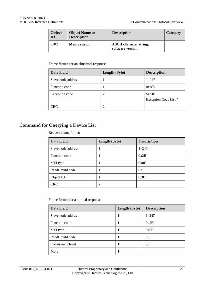
Command for Querying a Device List
Request frame format
Data Field Length (Byte) Description
Slave node address 1 1–247
Function code 1 0x2B
MEI type 1 0x0E
ReadDeviId code 1 03
Object ID 1 0x87
CRC 2
Frame format for a normal response
Data Field Length (Byte) Description
Slave node address 1 1–247
Function code 1 0x2B
MEI type 1 0x0E
ReadDeviId code 1 03
Consistency level 1 03
More 1

SUN2000 8–28KTL
MODBUS Interface Definitions 3 Communications Protocol Overview
Issue 01 (2015-04-07) Huawei Proprietary and Confidential
Copyright © Huawei Technologies Co., Ltd.
29
Data Field Length (Byte) Description
Next object ID 1
Number of objects 1
Object list
First object Object ID 1 0x87
Object length 1 N
Object value N
...
CRC 2
Object ID
Object Name Type Description
0x80-0x86 Reserved Returns a null object with a length of
0.
0x87 Number of
devices
int Returns the number of devices
connected to the RS485 address.
0x88 Information
about the first
device
ASCII character
string
See the device
description
definitions below.
Returns information only for the first
device if a network element allows
only one device to be connected to
each RS485 address.
0x8A Information
about the second
device
......
0xFF Information
about the 120th
device
Device Description Definitions
Each device description consists of all "attribute = value" strings.
Attribute label=%s;attribute label=%s;…attribute label=%s
For example:
1=SUN2000000;2=V100R001C01SPC120;3=P1.0-D1.0;4=123232323;5=2;6=1.
Attribute definitions

SUN2000 8–28KTL
MODBUS Interface Definitions 3 Communications Protocol Overview
Issue 01 (2015-04-07) Huawei Proprietary and Confidential
Copyright © Huawei Technologies Co., Ltd.
30
Attribute Label
Attribute Name
Type Description
1 Device Model ASCII
character string
SUN2000
2 Software version ASCII
character string
3 Version of the
communications
protocol
ASCII
character string
See the interface protocol version
definitions.
4 ESN ASCII
character string
5 Device number int 0,1,2,3...(Assigned by NE; 0 indicates
the master device to which the ModBus
card is inserted)
6 Parallel network
number
int 0, 1, 2, 3, … (assigned by NE)
0xFF: invalid value; indicates that a
unit does not belong to any parallel
system
If not applicable, this attribute is not
returned.
Frame format for an abnormal response
Data Field Length (Byte) Description
Slave node address 1 1–247
Function code 1 0xAB
Exception code 2 See 3.3.2 "Exception
Code List."
CRC 2


![DPU2000/1500R/2000R MODBUS / MODBUS PLUS … · DPU2000/1500R/2000R Modbus/Modbus Plus Automation Guide i DPU2000/1500R/2000R MODBUS / MODBUS PLUS ... [Catalog 587XXX00-XXX0 or 587XXXX6-XXX4]](https://img.dokumen.tips/doc/110x75/5acb9eac7f8b9a73128bdc42/dpu20001500r2000r-modbus-modbus-plus-modbusmodbus-plus-automation-guide.jpg)