Embed Size (px)
Citation preview

Preprint typeset in JINST style - HYPER VERSION
Summary of the Second Workshop on Liquid ArgonTime Projection Chamber Research andDevelopment in the United States
R. Acciarria, M. Adamowskia, D. Artripb, B. Ballera, C. Brombergc, F. Cavannaa,d ,B. Carlsa, H. Chene, G. Deptucha, L. Epprecht f , R. Dharmapalang W. Foremanh
A. Hahna, M. Johnsona, B. J. P. Jones i, T. Junka, K. Lang j, S. Lockwitza,A. Marchionnia, C. Maugerk, C. Montanaril, S. Mufsonm, M. Nessin, H. Olling Backo,G. Petrillop, S. Pordesa, J. Raafa, B. Rebela, G. Sininsk, M. Soderberga,q,N. Spoonerr, M. Stancaria, T. Strausss, K. Teraot , C. Thorne, T. Topea, M. Toupsi,J. Urheimm, R. Van de Waterk, H. Wangu, R. Wassermanv, M. Webers,D. Whittingtonm, T. Yanga
aFermi National Accelerator Laboratory, Batavia, IL 60510, USAbResearch Catalytics, USAcMichigan State University, East Lansing, MI 48824, USAdYale University, New Haven, CT 06520, USAeBrookhaven National Laboratory, Upton, NY 11973, USAf ETH Zürich, 8092 Zürich, SwitzerlandgArgonne National Laboratory, Argonne, IL, 60439, USAhUniversity of Chicago, Chicago, IL 60637, USAiMassachusetts Institute of Technology, Cambridge, MA 02139, USAjUniversity of Texas at Austin, TX 78712, USAkLos Alamos National Laboratory, Los Alamos, NM 87545, USAlIstituto Nazionale di Fisica Nucleare, Pavia 6-27100, Italy
mIndiana University, Bloomington, IN 47405, USAnCERN, 1217 Meyrin, SwitzerlandoPrinceton University, Princeton, NJ 08544, USApUniversity of Rochester, Rochester, NY 14627, USAqSyracuse University, NY 13210, USArUniversity of Sheffield, Sheffield, South Yorkshire S10 2TN, UKsUniversity of Bern, 3012 Bern, SwitzerlandtColumbia University, New York, NY 10027, USAuUniversity of California Los Angeles, Los Angeles, CA 90095, USAvColorado State University, Fort Collins, CO 80523, USA
– 1 –
FERMILAB-CONF-15-149-ND
Operated by Fermi Research Alliance, LLC under Contract No. De-AC02-07CH11359 with the United States Department of Energy.

ABSTRACT: The second workshop to discuss the development of liquid argon time projectionchambers (LArTPCs) in the United States was held at Fermilab on July 8-9, 2014. The workshopwas organized under the auspices of the Coordinating Panel for Advanced Detectors, a body thatwas initiated by the American Physical Society Division of Particles and Fields. All presentationsat the workshop were made in six topical plenary sessions: i) Argon Purity and Cryogenics, ii)TPC and High Voltage, iii) Electronics, Data Acquisition and Triggering, iv) Scintillation LightDetection, v) Calibration and Test Beams, and vi) Software. This document summarizes the currentefforts in each of these areas. It primarily focuses on the work in the US, but also highlights workdone elsewhere in the world.
KEYWORDS: Noble liquid detectors, Time projection chambers, Neutrino detectors.

Contents
1. Introduction 1
2. Physics Requirements for Neutrino Experiments 2
3. Argon Purity and Cryogenic Systems 23.1 LBNE 35 ton Prototype Cryogenics 33.2 MicroBooNE Cryogenics 53.3 LAr1-ND Cryogenics 63.4 Catalytic Purification for Science and Industry 7
4. TPC and High Voltage 84.1 Liquid Argon Dielectric Strength Measurements 84.2 High Voltage Surge Protection Systems for LArTPC Detectors 104.3 High Voltage Feedthroughs 124.4 LBNE Prototype TPC in the 35 ton Membrane Cryostat 14
5. Electronics, Data Acquisition, and Triggering 155.1 Front-end Electronics 155.2 Cold Digital Electronics (COLDATA) 175.3 Data Acquisition 195.4 Time Stamping and Detector Synchronization 20
6. Scintillation Light Detection 216.1 Test Stands Available for R&D 226.2 Recent Advances in Photon Detection 22
6.2.1 PMT-Based Photon Detection 226.2.2 Enhanced VUV Photon Collection from Detector Walls 236.2.3 Progress Toward a Cryogenic LAPPD 246.2.4 Light Guides for Large-Area Photon Detection 25
6.3 Effects of Contaminants on Scintillation Light 266.4 Characterization of Silicon Photomultipliers for Photon Detection Systems 286.5 Design Considerations from Physics and Engineering 29
6.5.1 Physics-Driven Design Requirements 296.5.2 Timing Resolution 296.5.3 New Approaches to Geometric Coverage 29
7. Calibration and Test Beams 307.1 Calibration 30
7.1.1 Charge 307.1.2 Light 32
7.2 Test Beams 33
– 1 –

8. Software 368.1 LArSoft: Simulation and Reconstruction Software 368.2 Simulation of Liquid Argon TPC’s 388.3 Signal Processing and Reconstruction 39
9. World Wide R&D Efforts 409.1 Development in Continental Europe 409.2 Development in the United Kingdom 41
10. Summary 42
11. Acknowledgments 43
1. Introduction
Liquid argon time projection chambers (LArTPCs) have found wide acceptance as detectors forneutrino experiments to study neutrino oscillations and cross sections. These detectors are expectedto be the primary detectors for future short- and long-baseline oscillation experiments. The basicprincipal behind the LArTPC is that a minimum ionizing charged particle passing through the liquidargon produces 55,000 electrons and 80,000 scintillation photons for every centimeter traversed.The total number of ionization electrons and scintillation photons are proportional to the energydeposited in the medium. The electrons are drifted in a uniform electric field toward a readout; theuniform field provides a constant drift velocity, allowing one to determine with excellent resolutionthe location in the drift direction at which the ionization occurred. This resolution provides neutrinoexperiments the ability to digitally record bubble-chamber-like images of the neutrino interactions,allowing researchers to distinguish between different interaction processes with certainty. Thescintillation light is also proportional to the energy deposited by the particle and a combination ofthe charge and light information provides the best measurement of the calorimetric energy of theinteraction.
This document is the summary of the second workshop held at Fermilab to discuss the cur-rent efforts to develop LArTPC detectors in the US [1]. The workshop, held July 8-9, 2014, wasorganized under the auspices of the Coordinating Panel for Advanced Detectors (CPAD), a stand-ing panel that was empowered by the American Physical Society Division of Particles and Fields(DPF). CPAD is intended to promote national detector R&D programs and stimulate new ideas ininstrumentation development. CPAD also facilitates coordination among the national HEP labo-ratories and university groups engaged in detector R&D and the use of targeted resources at thenational laboratories.
This second workshop was attended by 85 individuals from 32 institutions. All presentationsat the workshop were made in plenary sessions organized into these topical categories: i) ArgonPurity and Cryogenics, ii) TPC and High Voltage, iii) Electronics, Data Acquisition and Triggering,iv) Scintillation Light Detection, v) Calibration and Test Beams, and vi) Software. This document
– 2 –

summaries the information presented in those sessions in the sections below. The work for severalefforts can be placed in more than one of the topical categories. As such, the reader will findaspects of those projects described throughout the document. Important lessons learned in any ofthose areas that are key to building LArTPC experiments are preceded by a "Learned Lesson" tagin the text.
2. Physics Requirements for Neutrino Experiments
The major physics measurements proposed for large LArTPCs in long baseline experiments arethe determination of the mass ordering and the precision measurement of the parameters definingthe PMNS mixing matrix, particularly the CP violating phase δ . The detection of a supernovacore-collapse event, relic supernova neutrinos, and the determination of the least upper bound forthe proton partial lifetime in one or more important decay modes are also major goals that can beaccomplished with very large LArTPCs located deep underground. Smaller LArTPCs can be usedto resolve the conflicting observations of short baseline neutrino oscillations and the observationof coherent neutrino scattering and measurements of cross sections for this process. Successfullyachieving these goals with LArTPCs will require additional studies to develop a precise understand-ing of cross sections for neutrino and anti-neutrino interactions in argon, and a detailed knowledgeof the final state interactions and other nuclear effects.
The successful achievement of these physics goals places many demands on the performanceof LArTPCs, and on our understanding of the processes involved in producing the observed chargeand light signals and on the backgrounds that accompany the desired signals. For the precise deter-mination of cross sections, clean identification of the final reaction products is required. This goalalso demands precise energy loss and range determination, precise total energy measurement forisolated tracks as well as showers, and high spatial resolution, especially near the vertex. In general,the high spatial resolution and ability to separate multiple closely spaced tracks gives LArTPC theability to use topological classification to help identify events in the presence of final state interac-tions and to reconstruct total energy. To properly separate neutral and charged current interactions,good separation of electron- and photon-induced showers obtained by observing the charge densityat the beginning of the showers is required. The identification of final state interactions will requirelow energy thresholds in order to observe, for example, Compton scattered photons from nuclearde-excitation and low energy argon recoils from neutrons. To separate neutrino and anti-neutrinocharge current interactions, charge determination of the outgoing muon is required. This separationcan be done by creating a magnetic field in the detector, or alternatively through statistical meansby observing µ− capture. In the latter case, the cross section for µ− capture needs to be well de-termined. For supernova neutrino detection and coherent neutrino-nucleus scattering low energydetection thresholds will be required. For coherent neutrino scattering, in particular, the thresholdsare so low (keV) that scintillation light is the only useful signal available.
3. Argon Purity and Cryogenic Systems
Fermilab has the most experience in designing and operating liquid argon systems in the US. Cryo-genic solutions and argon purification systems have been developed, built and successfully operated
– 3 –

at Fermilab in a suite of dedicated test stand devices and physics experiments. At present, someof these devices have completed their program, like ArgoNeut [2] and the LAPD (Liquid ArgonPurity Demonstrator) [3], some other are in the course of operation, such as the LBNE 35 ton pro-totype [4], or about to start, like MicroBooNE [5], and new devices are currently in the designingphase, such as LAr1-ND [6]. In the following subsections some aspects of the cryogenics andpurification features of these devices and of the results, where available from their operation, arebriefly outlined.
Removal of oxygen for the ultra-purification of liquid argon is of primary importance andoxygen getters are an integral part of the purification system for all these devices. New, higher-capacity materials are being developed mainly for industrial applications. Possible applicationof these new products for science is of great interest and Fermilab is currently involved in a testcampaign in collaboration with specialized industries. A short report of the current status alongthis line of development is also provided at the end of this section.
All systems described below are reusing or improving designs initially developed with theLAPD. The primary set of information from the LAPD were how to efficiently construct the sys-tems and the operation of the cryogenic pumps and filtration system. The LAPD also providedthe first measurement of the loading capacity for an oxygen filtering media used in liquid argonoperation [3].
3.1 LBNE 35 ton Prototype Cryogenics
The LBNE 35 ton prototype, shown in Fig. 1, was built in 2013 at Fermilab. First operation of theprototype was a success and met its goals. The prototype demonstrated the contractual businessmodel with a membrane cryostat supplier for the design and construction of a membrane cryostat.The initial operation also demonstrated the membrane cryostat technology for liquid argon servicewith respect to thermal performance, feasibility for liquid argon, and leak tightness. This operationalso achieved and sustained the purity required for the LBNE Far Detector which is an equivalentoxygen contamination of less than 229 ppt, corresponding to an electron lifetime greater than 1.4milliseconds.
The LBNE 35 ton prototype utilizes the LAPD purification system which is located in theProton Center area at Fermilab. The cryostat liquid volume is 27,700 liters with a maximum depthof 2.57 meters. The cryostat is insulated with 0.4 meters of polyurethane foam. A 0.3 meter thickconcrete shell provides the mechanical strength to resist the pressure load which is transferred fromthe liquid containing stainless steel membrane through the foam insulation. The tank contains twosubmerged liquid argon pumps which direct the liquid argon up and out of the tank and throughtransfer lines to the LAPD purification system. The required liquid purity was achieved one monthafter system startup. Following the procedure developed for the LAPD [3], the first purification stepwas an argon piston purge where room temperature argon gas was injected at a rate of 2.43 volumechanges per hour into the cryostat which initially contained breathable air. The argon piston purgereduced the oxygen concentration to from 21% to 6.3 ppm, water from 550 ppm to 1.2 ppm, andnitrogen from 78% to 10.6 ppm. The concentration of contaminants in a room temperature tankfilled with gas is reduced by a factor of 840 due to the liquid to vapor mass ratio such that thatargon piston purge need not achieve purity lower than a few ppm.
– 4 –

Figure 1. Overview of the LBNE 35 ton prototype cryostat and the portion of the cryogenic system that wasnot part of LAPD.
A room temperature gas recirculation then pulled argon gas out of the tank at a rate of 7.5volume changes per day and sent it through the water and oxygen filters. This phase revealed aleaking vacuum relief valve which would have been far more difficult to identify during cryogenicoperation. The gas recirculation phase reduced oxygen concentration to less than 100 parts perbillion (ppb), water was reduced to less then 400 ppb, and the nitrogen concentration was 48 ppm.Nitrogen is not actively filtered and can only be reduced by the dilution effect of argon gas addedto the system to replace the argon gas sent to the gas analyzers. Nitrogen was higher at the endof the gas recirculation phase than at the end of the argon piston purge due to the leaking vacuumrelief valve discovered during the gas recirculation phase.
The cryostat was cooled down using a system of liquid argon atomizing sprayers over a periodof 28 hours and then filled with liquid argon. Refrigeration is provided by a liquid nitrogen poweredcondenser. The condensed argon boil off, which contains the majority of the contamination dueto outgassing from warm surfaces located in the ullage, is sent to the pump suction such that itis filtered prior to returning to the tank bulk liquid. Pumped liquid filtration achieved electronlifetimes in excess of 2.5 milliseconds. The electron lifetime trend was upward such that a longerperiod of filtration would likely have achieved larger electron lifetimes.
One submersible pump suffered premature bearing wear at 750 hours. After the run was overthe second pump was also found to have excessive bearing wear. The pump manufacturer has notdetermined the reason for excessive bearing wear. The electron drift lifetime was measured in theliquid argon using a purity monitor. The purity monitor was based on the ICARUS design [7]. Athorough description of the purity monitor and the data acquisition hardware and software can befound in Reference [3]. As described in Reference [3], a measure of electronegative impurities canbe determined from looking at the fraction of electrons generated at the cathode that arrived at theanode. The purity monitors exhibited microphonic noise due to being supported from a large flat
– 5 –

Figure 2. Plots of water (left) and oxygen (right) contaminations in MicroBooNE cryogenic system asmeasured by the gas analyzers as clean-up began for the partially outfitted test. The measurement of thewater contamination came from the Tiger Optics Halo+. The measurement of the oxygen contaminationcame from the Servomex DF-560E.
plate that also supports the cryogenic system. Installation of a time projection chamber (TPC) isplanned for the second operation of the system in 2015.
Lessons Learned
• The gas recirculation step when commissioning a cryostat is very important as it is a finalsystem integrity check before committing to cryogenic operation.
• The purity monitor devices should be isolated from even small amounts of vibration to ensuretheir stable operation.
3.2 MicroBooNE Cryogenics
The first cryogenic system for LArTPC detectors at the scale of 100 tons built in the US is for theMicroBooNE experiment. Fabrication of the system was successfully completed in 2014 as was theinstallation in its final experimental enclosure. The major cryogenic subsystems of MicroBooNEare: i) the initial cool down system, ii) the purification system, and iii) the nitrogen refrigerationsystem. A partially outfitted test was carried out and the results are summarized here below. Thetest incorporated a few hundred liter capacity cryostat, which is not part of the final system, to testdielectric breakdown as a function of electronegative contamination [8].
The MicroBooNE cryogenic system consists of two filter skids, each comprised of two pres-sure vessels, two pumps to circulate the argon, although only one will be in use at any given time,and a liquid nitrogen-based refrigeration system. In each filter skid, one pressure vessel containsa 4A molecular sieve supplied by Sigma-Aldrich to eliminate water [9] and one contains BASFCU-0226 S, a dispersed copper oxide impregnated on a high surface area alumina to eliminateoxygen [10] from the argon. The filtration system consistently produced better than 100 ppt oxy-gen equivalent contamination to the cryostat used for breakdown studies as well as the rest of thesystem.
The oxygen contamination level in the argon was monitored using two Servomex gas analyz-ers, a DF-310E and a DF-560E [11]. Combined, the two oxygen analyzers covered a range of
– 6 –

0.1 ppb to 5000 ppm. The level of nitrogen contamination in the argon was monitored using anLD8000 Trace Impurity Analyzer [12]. The level of water contamination in the argon was moni-tored using a Tiger Optics Halo+ gas analyzer [13]. Plots of the water and oxygen contaminationsas filtration started up appears in Fig. 2.
In addition to the gas analyzers, contamination values ranging between 300 and 50 ppt oxygenequivalent were measured with purity monitors based on the design used in the LAPD and LBNE 35ton prototype. During this operation, the cryogenic system achieved a measured electron lifetimeof better than 3.5 ms.
3.3 LAr1-ND Cryogenics
A short-baseline neutrino (SBN) program is being developed at Fermilab to study neutrino prop-erties using a combination of detectors: the existing MicroBooNE, the newly proposed LAr1-NDupstream of MicroBooNE, and a refurbished ICARUS T600 downstream of MicroBooNE. Themain features of the cryostat and cryogenic systems that are being developed for LAr1-ND aresummarized here. It is a truly international effort with US and European participation and twocryogenic groups at Fermilab and CERN to support SBN and long-baseline neutrino (LBN) ac-tivities. While the SBN program is independent of the LBN program, it has similar cryogenicrequirements and presents similar challenges; the primary challenge being the achievement andmaintenance of the liquid argon purity in a membrane cryostat. There is a strong incentive to useexisting knowledge and expertise and perform tests and prototyping taking into consideration theneeds of both programs. For example the use of external liquid argon recirculation pumps, and acold roof, kept at temperatures lower than 100K, will be implemented in LAr1-ND. If successful,these techniques may be part of the design of the LBN far detector. The reason for the externalpumps resides in the potentially high maintenance required to operate the submerged liquid argonpumps as mentioned in § 3.1. The ullage is known to be the main source of water in the liquidargon and a cold roof could reduce the contamination in the ullage by limiting the potential out-gassing. The cryostat and cryogenic systems will be designed and built with the needs of the futureLBN program in mind. The cryostat is proposed to be located in a new building located next tothe Fermilab SciBooNE enclosure; that enclosure will house the cryogenic system. The cryogenicpiping connecting the cryostat to the rest of the system will run in an underground tunnel linkingthe two buildings. The cryostat builds on the successful experience of the LBNE 35 ton membranecryostat prototype described in § 3.1. Figure 3 shows the 3-D model of the LAr1-ND membranecryostat in its current base configuration with inner dimensions 4.4 m (width) × 6.1 m (length) ×4.8 m (height). It will contain about 129 m3 of liquid argon and will have 0.45 m of polyurethaneinsulation all around. A concrete or steel support structure will sustain the liquid and gas loads.The current configuration shows two plates at the top: plate A, which is part of the membrane andinsulated with polyurethane, and plate B, which is not part of the membrane as it contains all thepenetrations and is insulated with radiation shields. The gas argon is foreseen to be contained inthe neck region underneath plate B with the liquid argon touching the membrane underneath plateA. The cryogenic system will use the piston purge method [3] to remove the impurities from thetank prior to cryogenic operations. It has a goal liquid argon purity of 50 parts per trillion oxygenequivalent contamination, which correspond to a 6 ms electron drift lifetime. The liquid argon will
– 7 –

Figure 3. 3-D model of the LAr1-ND membrane cryostat
be purified using a combination of molecular sieve and copper beads filters to remove water andoxygen respectively, as was done in the LAPD, the LBNE 35 ton prototype and MicroBooNE.
Figure 4. Process Flow Diagrams of the LAr1-ND liquid argon (left) and liquid nitrogen (right) systems.
Figure 4 shows the Process Flow Diagrams (PFD) for the liquid argon and liquid nitrogensystems. The main features are the receiving facilities, located above ground, with the transferlines to deliver the cryogens underground; the liquid argon handling and purification system; thegaseous argon filtration to purify the gas after the piston purge; the condenser to re-condense theboil-off argon from the cryostat; the gas analyzers to measure the impurities; and the liquid nitrogendistribution facility and pumping station. All these systems are located underground.
3.4 Catalytic Purification for Science and Industry
Purification catalysts find major applications in various sectors of the chemical processing indus-
– 8 –

try, like catalytic oxidation, deoxo and oxygen getter catalysts. Removal of oxygen using oxygengetters in particular for the ultra-purification of liquid argon is the primary application for science.This section provides a summary of the current achievements and perspectives from current de-velopments with new materials [14]. Oxygen Removal using Oxygen Getters is a core technologyat Research Catalysts. Several “standard" getter products are available, including the one mostwidely used in liquid argon, Engelhard Q-5, as well as several others with higher capacities. Thebest known of the higher capacity getters is the BASF Catalyst R3-11G. Additionally, based ontesting of these and other materials for oxygen capacity, two new, higher-capacity materials areavailable to the market, namely GetterMax R© 133 and GetterMax R© 233.
The oxygen capacity of a given catalyst will vary with operating conditions, commonly in-dicated by the dynamic capacity of oxygen getters, most notably with temperature but also withcontact time, the inlet oxygen concentration, and the allowable oxygen outlet concentration. Ca-pacities for the most commonly used getters, when operated in gas phase at 25C, range from about1 liter of oxygen per kilogram of catalyst for Q-5, to around 4 liter per kilogram for R3-11G, to up-wards of 10 and even ≥ 20 liters per kilogram for the more powerful getters. These more powerfulgetters have higher bulk densities, which translates into even greater capacity gains per unit of bedvolume.
Copper-based oxygen getters are used in various liquid-phase applications too, including propy-lene monomer and various solvents including tetrahydrofuran (THF), methanol, and alkanes suchas hexane and heptane. However, industry does not typically make systematic attempts to measureperformance of oxygen getters for treating sub-ambient temperatures in either liquid or vapor phaseservice. Nevertheless, based on their relative performances in vapor phase at room temperature, onecould expect that the GetterMax R© materials, which have shown significantly higher capacity thanboth R3-11G and Q-5 in benchmarking tests, will provide performance advantages in liquid argonas well.
As indicated above, little is known about the capacities of the oxygen getters in liquid phaseservice and how those capacities may vary with contact time, temperature, and levels of dissolvedoxygen. Fermilab has reported a capacity factor for Q-5 in liquid argon of about 0.5 gram per kilo-gram [3]; in the units more commonly used to benchmark getter capacity, this value is equivalentto about 0.35 liters of oxygen per kilogram of catalyst. This value is lower than the room temper-ature value suggesting the capacity in purification of liquid argon may be only about 30% of thatobtained in gas phase at 25 C, at least with Q-5.
Research Catalysts has expressed interest in expanding its portfolio of oxygen getters andthe envelope of knowledge about their performance, particularly in liquids and at sub-ambienttemperatures. It welcomes opportunities to collaborate in this area with the Physics community.
4. TPC and High Voltage
While LArTPC experiments have operated successfully in the past [15, 16], the technology is beingpushed in the design of future experiments by increasing the detector volume and possibly the driftlength. Reliable methods are needed to deliver increasingly high voltages (HV) inside the cryostatto the TPC. A better understanding of the liquid argon dielectric properties is necessary, as well as
– 9 –

the development of protection systems against possible HV discharges. Prototypes are needed totest in detail the main design features of the envisioned large future detectors.
4.1 Liquid Argon Dielectric Strength Measurements
The understanding of liquid argon dielectric properties is crucial for the design of future experi-ments. Recently, it became apparent that the often-quoted 1 MV/cm liquid argon dielectric strengthmeasurement [17, 18] was not valid at the distance scales important to LArTPC design. This real-ization motivated several new studies.
The ETH Zurich group measured the liquid argon dielectric strength in a uniform field over a1 cm gap distance and a 20 cm2 cathode area [19]. The field was formed using Rogowski profilesthat were mechanically polished. This geometry withstood a field of 100 kV/cm without breakdownover four hours when the liquid argon was below the boiling point at a given pressure. When thepressure in the vapor space was decreased to bring the liquid argon to the boiling point, dielectricbreakdowns were observed at fields as low as 40 kV/cm. This was interpreted as evidence thatbubbles contribute to dielectric breakdown in liquid argon.
The LHEP Bern group also published a result measuring the liquid argon dielectric strength [20].They measured the dielectric breakdown voltage in liquid argon, with 1 ppb electronegative impu-rities, below the boiling point between a 80 mm diameter cathode sphere and a grounded plate forgap spacings up to the centimeter scale. Liquid argon dielectric breakdowns were observed forfields as low as 40 kV/cm. For gap spacings greater than 1 cm, they noted an unexpected behaviorof breakdown along the feedthrough surface.
A second published study by the group at LHEP Bern described a method to suppress dielectricbreakdowns in liquid argon [21]. They used a similar geometry as their previous test, but here, thecathode sphere was coated with a several hundred micrometers layer of natural polyisoprene toinhibit discharges by suppressing field emission. Breakdown fields were more than an order ofmagnitude higher with a 450 µm layer than without while using a 4 cm diameter sphere at a 3 mmgap spacing.
A Fermilab group recently completed measurements of liquid argon dielectric strength with agoal of studying geometry and purity effects [8]. The test cryostat was plumbed into the MicroBooNEcryogenic system with access to pure argon, gas analyzers to determine the oxygen, water and ni-trogen contamination in the argon, and a downstream purity monitor. A MicroBooNE productionhigh-voltage feedthrough was used to supply high voltage to a sphere-plate geometry for dielectricbreakdown studies. Cathode sphere diameters of 1.3, 5.0 and 76 mm were evaluated in puritiesranging from a few parts-per-million (ppm) to tens of parts-per-trillion (ppt) oxygen-equivalentcontamination and at anode-cathode spacings up to 25 mm. Distances above 15 mm for the 5 mmdiameter sphere and 10 mm for the 76 mm diameter sphere were not considered in the results be-cause breakdown along the feedthrough was observed for some of the data beyond these distances.
A comparison of the Fermilab group’s results to earlier data, including those of the Bern group,can be seen in Fig. 5. The two sets of points for each probe of the Fermilab data show the resultsfrom the highest and lowest argon purity data collected. While the data of the different groups areconsistent with each other, a noticeable geometry effect can be seen.
A purity effect was seen by the Fermilab group for the 1.3 mm probe at gap distances greaterthan 10 mm. For purities between 0.2 and 1.4 ppm, the breakdown voltage was about 1.5 times
– 10 –

Distance [cm]-310 -210 -110 1
Bre
akdo
wn
field
[MV
/cm
]
-210
-110
1
10
Swan and Lewis, r=2.5mm, 20% O2 Swan and Lewis, r=2.5mm, 1% O2Swan and Lewis, r=2.5mm, 0.002% O2 Swan and Lewis, r=2.5mm, 0.00002% O2LHEP U. of Bern r=20 mm, 20 ppm O2 LHEP U. of Bern r=20 mm, 3 ppb O2 LHEP U. of Bern r=40 mm, 1 ppb O2 LHEP U. of Bern ARGONTUBE, r=10-200 mm, 0.1 ppb O2FNAL r=0.65 mm; 1.4 ppm O2 FNAL r=0.65 mm, 291 ppt O2*FNAL r=2.5 mm, 1.3 ppm O2 FNAL r=2.5 mm, 775 ppb O2FNAL r=38.1 mm, 1.5 ppm O2 FNAL r=38.1 mm, 86 ppt O2*
Figure 5. A comparison of the several measurements of the magnitude of the electric field at breakdownin liquid argon [20, 8]. The data points from Fermilab result from the highest and lowest contaminationlevel measurement taken with each probe. The oxygen values with an asterisk are extrapolated from puritymonitor measurements.
)2 Area (cm-310 -210 -110 1 10
Fie
ld (
kV/c
m)
Max
E
210
31076 mm5.0 mm1.3 mm
)2 Area (cm-410 -310 -210 -110 1
Fie
ld (
kV/c
m)
Max
E
210
31076 mm5.0 mm1.3 mm
Figure 6. The average maximum breakdown field versus stressed area of the cathode. (left) The stressedarea is defined as the area with an electric field greater than 80% of the maximum electric field. (right) Thestressed area is defined as the area with an electric field greater than 90% of the maximum electric field.
greater than for purities between 0.29 and 1.8 parts-per-billion (ppb). No noticeable purity effecton dielectric strength was observed with the other cathode tips.
A dependence on peak electric field at breakdown and stressed area was also observed andshowed similar behavior across the geometries evaluated in the Fermilab test. A stressed area orvolume dependence was suggested by Gerhold et al. [22] in describing liquid helium data. Here,a stressed area is defined as the area on the cathode surface that is equal to or greater than somepercentage, ε , of the peak electric field. Plots of the peak electric field at breakdown versus thestressed area are shown in Fig. 6 for ε values of 80% and 90%.
Lessons Learned It appears there are several conditions that can cause liquid argon to have a
– 11 –

dielectric strength of less than 1MV/cm. Those conditions include i) boiling of the argon, creatingbubbles in the region of the high electric field, ii) field emission, and iii) large stressed area of thecathode surface.
4.2 High Voltage Surge Protection Systems for LArTPC Detectors
Dependencies of the breakdown mechanism on electrode geometry, surface finish, argon purity,and space charge accumulation are only partially understood as the present time [20, 17, 21, 8].These dependencies make it difficult to predict where and how frequently breakdowns will occur.As such, it is important to take whatever steps are necessary to design TPC field cages to be robustagainst failure in the event of HV discharges.
As described in [23], the effects of a HV discharge from a point on the TPC field cage can leadto a large transient overvoltage, whose relaxation time and distribution over the field cage elementsdepend upon the distribution of capacitances and resistances in field cage-cathode-cryostat system.Electrical models of the MicroBooNE [5] field cage showed that such transients could exceed thefailure voltage of the originally installed field cage resistors [24].
To address this problem, a two-fold solution was implemented. First, some of the most vulner-able resistors were replaced with more robust components capable of withstanding larger transientvoltages. Second, a high voltage surge protection system was implemented on the field cage, whichprevents large overvoltages from evolving between field cage rings in a HV discharge situation.This use is the first application of a surge protection system in a cryogenic LArTPC detector.
The MicroBooNE surge protection system uses surge arrestors connected between the TPCfield cage rings in parallel with the field cage resistors. A surge arrestor is a device which has a non-linear voltage-current (V-I) characteristic, and commonly used commercial surge arrestors includegas discharge tubes (GDTs) [25, 26] and varistors [27]. Surge arrestors suitable for MicroBooNEare highly insulating at the nominal ring-to-ring voltage, but become conducting when a largeovervoltage is applied. This means that in normal running conditions the surge arrestor does notinterfere with the voltage distribution on the field cage or draw a large leakage current. In the eventof a HV discharge, however, charges on the field cage are allowed to redistribute quickly to preventdamaging voltages from being held between field cage rings and damaging field cage resistors.
High voltage GDTs [28] and varistors [29] were both tested for the MicroBooNE application,and a detailed report of this testing can be found in [23]; two plots from that reference are repro-duced in Fig. 7. The devices were tested in cryogenic conditions for their insulating resistance,clamping behavior and robustness under high voltage and high energy surges. Effects on liquidargon purity and ambient photon background were also studied. Both classes of device were foundto be suitable for surge protection on LArTPC field cages. Varistors were chosen for MicroBooNEdue to their continuous V-I characteristic, which provides a smooth clamping behavior rather thana crowbar action.
As well as ensuring suitability of the devices for operation in a cryogenic environment, theclamping behavior of a varistor based system was investigated in situ on the MicroBooNE fieldcage. Since a 2 kV ring-to-ring voltage could not be applied in air, a lower applied voltage wasused, with correspondingly lower voltage varistors and smaller resistors installed across the firstten field cage tubes. The tenth field cage tube was connected to ground via a 1.25 GΩ resistanceto simulate the resistive effect of the rest of the field cage. This produces a "scale model" of the
– 12 –

Figure 7. Two figures reproduced from [23]. (left) the clamping voltage of a large sample of varistorswarm (room temperature) and cold (90 K). (right) The clamping voltage of varistors before and after theapplication of 10 × 2 Joule surges
MicroBooNE field cage, with the correct geometrical capacitances but lower resistances. A voltageof up to 1 kV was applied to the cathode and then points in the system were discharged to groundas the HV supply was removed from the cathode using a double-pole-double-throw switch. Asshown in Fig. 8, without varistors applied, a large transient overvoltage was seen between adjacentfield cage tubes With varistors applied, the tube-to-tube voltage is effectively clamped and largeovervoltages to not occur.
Other in situ tests were made implementing a finite HV supply trip time after discharge, andwith incomplete discharge of the cathode. In all scenarios investigated, the surge protection systemacted as expected, clamping transient overvoltages between any pair of field cage rings.
0 1 2 3 4 5 6 7 8 9
Gap number
Figure 8. Demonstration of clamping properties of varistors on the MicroBooNE TPC. (left) The circuitdiagram of "scale model" used to test the surge protection principal. (right) The maximum evolved ring-to-ring voltages in the protected and unprotected systems.
Lesson Learned High voltage discharge near the cathode can be a disaster for LArTPCs. As
– 13 –

Table 1. Summary of High Voltage feedthroughs developed for running experiments or test setups
Project Design HV Required HV Operated HV Tested HV(kV) (kV) (kV) (kV)
ICARUS 75 75 150 150ZEPLIN II 25 25 21DarkSide10 50 36 36 50DarkSide50 50 12 12 50XENON1T 100 100 Being installedXENON1T prototype 100 100 130mini-CAPTAIN 20 20 75CAPTAIN 50 50 75LBNE prototype 200 175 200LBNE 35 ton 200 111 170
such, it is important to consider implementing some form of surge protection on the detector.
4.3 High Voltage Feedthroughs
High voltage feedthroughs (HVFT) are an important component of LArTPC detectors. Electricfields of ∼ 500 kV/cm are typically used as drift field for the ionization electrons. A 3.5m longdrift as in the planned LBNE detector will require a 175 kV nominal operating voltage. A reliablemethod to deliver the needed high voltage through the cryostat to the TPC cathode has been a majorchallenge in the LArTPC development.
Ultra-High-Molecular-Weight-Polyethylene (UHMWPE) cryo-fitted HVFTs have been devel-oped and built for many experiments as listed Table 1. An inner conductor, carrying HV, is insulatedby UHMWPE from an outer conductor tube, kept at ground [15, 30].
The basic principle is to cryo-fit a ∼ 1 inch long section of the feedthrough. An inner smoothsolid core, the insulating UHMWPE, is cryo-fitted into an outer conductor tube with a smooth in-ner surface in order to create a vacuum-tight seal. The location of this section is such that duringoperation it is always kept at room temperature. Depending on the manufacturer and on the par-ticular batch, UHMWPE shrinks by ∼ 1.8−2% when cooled to liquid nitrogen temperature. Theshrinkage of each given UHMWPE sample is carefully measured, and its inner and outer diametersare precisely machined to specific values to match the outer conductor inner diameter and the innerconductor outer diameter for the cryo-fitting procedure. Leak tests are normally performed wherethe side of the feedthrough exposed to air is sealed by a helium filled balloon. The requirementis to reach a leak rate less than 1× 10⁻¹¹ atm-cc/sec after a 10-20 minute wait. The thickness ofthe UHMWPE insulator is chosen to meet the design needs. In most practical cases, the neededthickness for ease of construction and to obtain a good seal is already much larger than electricallyrequired [30].
The highest voltage feedthrough is the prototype built for LBNE, which has been repeatedlytested up to 200 kV. However an identical feedthrough in design and construction for the LBNE 35ton prototype detector, seen in Fig. 9, has never reached 200 kV without discharge above ∼ 150 kV.A careful examination revealed that a minor mechanical detail, but very important feature, was
– 14 –

Figure 9. The feedthrough for the LBNE 35 ton prototype.
Figure 10. Schematics of the filter box circuitry. The value of the resistors need to be customized, thecapacitors represent the intrinsic cable and detector capacitances. In addition the filter box contains a coronadischarge monitor, represented by the yellow box next to the resistors.
neglected in the final machining. The three small holes on the outer conductor, designed to avoidargon gas bubble build up at the bottom of the conductor, were missing. This change is the onlydifference compared to the successful LBNE prototype feedthrough. A distinctive feature of theLBNE and of the LBNE 35 ton feedthroughs, as shown in Fig. 9, is that the outer conductor flaresout at the bottom. The space at the flare is filled by UHMWPE. This feature is thought to beessential in order to reach 200 kV. In addition the LBNE feedthroughs are equipped with a customHV filtering box, as shown in Fig. 9 and Fig. 10. This filtering box is to minimize the ripple fromthe HV power supply, which would induce noise on the charge amplifiers reading out the TPC wireplanes.
4.4 LBNE Prototype TPC in the 35 ton Membrane Cryostat
The salient features of the conceptual design of the liquid argon Far Detector (FD) for the LBNEexperiment are summarized in Ref. [31]. The FD includes multiple membrane cryostat modules of5 kiloton fiducial volume. Figure 11 shows the layout and the cross-section of the FD.
The original program for the LBNE liquid argon FD had a 1 kiloton prototype cryostat (LAr1)that would have been used to verify the full scale components of the conceptual design. Howeverduring a reconfiguration of LBNE in 2012, that prototype was cancelled due to cost considerations.The LBNE 35 ton prototype cryostat was originally built to demonstrate the feasibility of the mem-brane style cryostat for high purity liquid argon operation. In order to provide a verification of theFD design, the 35 ton cryostat was given a new additional purpose meant to test as many of theFD design choices as possible, within the limited size of the detector. The available volume for adetector in the 35 ton prototype cryostat is limited to roughly 2.7×2.4×2.2 m3. In addition, entryinto the cryostat is through a 75 cm diameter manhole access.
The features that were deemed important to the prototype detector design were the doublesided nature of the APA wire plane assemblies, and the edges between APAs. This gave rise to the
– 15 –

Figure 11. LBNE Far Detector design of the anode and cathode configuration (left) and two 5 kiloton(fiducial) volume cryostats (right).
Figure 12. The LBNE 35 ton Prototype Cryostat and Detector
detector shown in Fig. 12. There are two drift regions, one 2.23 m long and the other 27 cm. TheAPA plane is comprised of 4 APAs, two long on each side with two short APAs in the middle. Allare 50.4cm wide, with the long APAs having an active height of 196.3 cm. The two short APAsare slightly different lengths (top 112.3 cm and bottom 84.3 cm) in order to fit in the same verticalspace as the long APAs. The mass of the total active drift volume is 10.2 tons of liquid argon.
5. Electronics, Data Acquisition, and Triggering
5.1 Front-end Electronics
The BNL group is continuing the development of a complete front-end signal processing chain thatoperates in liquid argon. Two ASICs, an analog front-end ASIC and an ADC ASIC, have been
– 16 –

Figure 13. A prototype prototype front-end motherboard assembly developed for the LBNE 35 ton proto-type TPC.
designed based on new device models and design rules developed for a 180 nm TSMC CMOS pro-cess. This process allows the circuits to operate throughout the temperature range from above roomtemperature to below 77 K [32], with essentially invariant performance except for a reduction ofinput referred noise by about a factor of about 2 from 300 K to 77 K. The use of CMOS technologyand appropriate circuit design allows channel-to-channel and chip-to-chip variations of operatingparameters to be very tightly controlled. For example, charge gain and channel calibration ca-pacitance vary by about 0.1%, allowing simple charge calibration of all channels of an operatingdetector. Approximately 2000 of the 16 channel, low noise, low power analog front-end ASICshave been fabricated, and they are now deployed in multiple LArTPC experiments. These experi-ments include the MicroBooNE and LArIAT [33] experiments at Fermilab, ARGONTUBE [34] atthe University of Bern and CAPTAIN [35] at LANL. These ASICs have been fabricated into theLBNE 35t prototype TPC electronics, and they are planned for use in the LAr1-ND experiment atFermilab as well. In collaboration with CERN, ICARUS is considering using cold CMOS analogfront-end ASIC too. The MicroBooNE experiment has successfully installed 8,256 channels ofcold front-end electronics on a TPC that is sealed inside a cryostat. Based on this experience, theBNL group is making minor revisions to the analog front-end ASIC to improve the robustness andto simplify system design, principally by improving protection of inputs against electrostatic dis-charge, and by adding an programmable precision internal calibration pulse generator and a smartreset circuit.
A low power, clockless, 16 channel, 12 bit prototype ADC ASIC has also been designed,fabricated, and fully characterized in the lab. The effective resolution is 11.6 bits and the differentialnon-linearity is less than 4 least significant bits (LSBs) over 99% of the ADC range at both roomtemperature and 77 K. The performance of this ADC ASIC meets the requirements of the LBNEfar detector. A new ADC ASIC revision has been evaluated and will be used in the LBNE 35 tonprototype TPC.
The testing and operation of commercial Field Programmable Gate Arrays (FPGAs) at 77 Khas been investigated. A candidate FPGA, the ALTERA Cyclone IV GX, has been identified assuitable for use on front-end board at 77 K. This FPGA will aggregate data from 8 ADC ASICs,
– 17 –

and multiplex and transmit the data out of the cryostat. It can also perform digital signal processing,such as zero suppression and data compression. Studies of long term operation of commercial lowdropout (LDO) voltage regulators at 77K have identified few suitable devices. One candidate LDOregulator has been running at 77 K successfully for more than 12 months. Both FPGA and LDOregulator candidates will be used to equip the LBNE 35 ton prototype TPC. A prototype front-end motherboard assembly, with an analog motherboard and an FPGA mezzanine board, has beendesigned and used in tests of the LBNE 35 ton prototype TPC Anode Plane Arrays (APAs). Afull APA readout chain, including front-end motherboard assembly and a compact DAQ system,has been constructed and is being used to characterize APA assemblies. A picture of the front-endmotherboard assembly is shown in Fig. 13. Since the operating lifetime of commercial FPGAsat 77 K has not been established, and a digital ASIC for 77 K operation is being designed atFermilab, the front-end motherboard assembly is designed to allow simple swapping of the FPGAand digital ASIC mezzanine boards. This design of the front-end motherboard is also planned foruse in the LAr1-ND experiment and in the LBNE far detector, with incremental improvements asthe technology develops and with optimization for the particular TPC configuration.
5.2 Cold Digital Electronics (COLDATA)
With the front-end ASIC and ADC in liquid argon, it becomes desirable to also place digital elec-tronics near the front-end in the liquid. After digitization the data can then easily be sparsified,compressed or otherwise processed, and multiplexed for transmission out of the cryostat. Theseoperations all reduce the amount of information that needs to be transmitted, and the number ofcables required to transmit it. A reduction of cables in the cryostat results in less contaminationof the ultra-pure liquid argon caused by outgassing and cryostat penetrations. Cryostat design andreadout design are decoupled. As an example, a single APA would require 2400 lines to transmitindividual wires, but digitized at 2 Msps the same signals would require only 30 each of 2Gbpslines. This number can be reduced further by sparsification and compression.
Although FPGAs have been demonstrated to operate successfully in liquid argon, the operatinglifetime, limited by hot carrier injection, is not known and is difficult to determine for a commercialdevice designed for near room temperature environments. These considerations have motivated theneed for a digital multiplexor ASIC that is designed for operation at 77K for use in the LBNEfar detector. This work has begun by a team consisting of Grzegorz Deptuch and James Hoffat Fermilab, and of Tao Zhang, Tianwei Liu, Guoying Wu and Ping Gui at Southern MethodistUniversity (SMU), the goal of which is a COLDATA (COLd DAta Transmission ASIC) [36, 37].This chip will provide bidirectional data transfer to and from the BNL ADCs: an uplink at 2Gbpsand slow down link for control and setup, all with adequate redundancy. Several decision pointsare presently being studied and evaluated: i) should zero suppression and/or data compression beimplemented on chip? ii) which CMOS technology should be chosen, dependent on device modelsand CMOS electronics lifetime requirements? iii) should the digital chip operate synchronously orasynchronously? iv) do low drop-out voltage (LDO) regulators also need to be designed for longlifetime operation in liquid argon? v) what level of redundancy is desirable, i.e. duplication ofuplinks, reserve uplinks, clock links, lost clock / lost sync operation? vi) what testability functionsare desirable, i.e. reading back control and status data, generation of test data for uplink testing?
– 18 –

Current work on specifying and identifying COLDATA components has begun. A local clockoscillator device must be identified and evaluated for cryogenic operation. Candidate devices havebeen identified and are being evaluated. Transistor simulation models and device parameters forthe cryogenic temperature range are not available, and therefore test devices must be fabricatedand characterized to obtain them. Statistical data characterizing variation of model parameters andstatistical models of process and standard library digital cells are provided by foundries only nearroom temperature. These essentials for full custom, synthesized logic design and physical designverification need to be developed and verified for reliable use.
A preliminary investigation of the lifetime at cryogenic temperature of MOSFETs produced inthe Global Foundries CMOS digital process for two technology nodes, 130 nm and 65 nm, has beencompleted. An automated test setup for device parameter measurements at cryogenic temperatureshas been constructed at Fermilab. It consists of a cryogenic vacuum chamber with a cryocoolerand a computer control and measurement system. It implements an accelerated stress test method,which is the standard technique used to investigate the hot carrier degradation of MOSFET devices.This test applies voltages to the device that are higher than the nominal operating condition, andobserves the time for a device parameter such as VTH, ID, and gm to degrade, typically by 10%,from its initial value. The basic device physics quantitatively relates the damage at a shorter time athigher electric field to that in a longer time at lower electric field. This relation allows the measuredlifetime under stress to be extrapolated to a lifetime for acceptable device performance under adefined operating condition. The new automated test system allows devices to be tested for longertimes than it was possible before (in excess of 100 ks) and at lower stress voltages to achieve moreaccurate lifetime predictions. This system has been used to test 37 different MOSFET transistorsof several widths and lengths in 130nm and 65nm technologies. Similar results were found for bothtechnologies.
Lessons Learned
• The smallest length transistors at stress condition of VGS=VDS have the shortest lifetime.
• The width dependence of degradation at 77 K is not evident.
• The degradation at stress condition of VGS=VDS is worse than that of VGS= (1/2)VDSfor small length transistors.
Devices fabricated in either technology can be operated with long lifetimes at 77 K. For the130 nm devices, with a nominal supply voltage of 1.5 V, to achieve a 20 year lifetime, the powersupply voltage should be less than 1.49 V at the worst stress condition. For the 65 nm devices,with a nominal supply voltage of 1.2 V, to achieve a 20 year lifetime, the power supply voltageonly needs to be less than 1.30 V at the worst stress condition. Figure 14 shows the results of thesemeasurements, with lifetime increasing to acceptable values as VDS in decreased.
With these positive results, a R&D phase will now begin to extract basic transistor parametersat cryogenic temperature, including statistical variations, and add them to models for design ofbasic blocks, to develop a minimal digital library for synthesizable architecture of the COLDATAchip, and to investigate system architecture, and logic architecture required by data zero suppres-sion and compression. The first functional blocks to be developed in collaboration with SMU willbe a low-power PLL, a serializer and clock dividers for a 2 Gbps serializer. Following the final
– 19 –

Figure 14. The lifetime as a function of the inverse of the drain-source voltage of the transistor at 77 K fordevices fabricated in the 130 nm (left) and 65 nm (right) process. Lifetime is defined as the time to a 10%reduction of transconductance and drain current and by a 50 mV increase of threshold voltage.
decision to replace the present FPGA with the custom digital chip, work will begin on the design,prototyping and evaluation of major functional blocks, such as a line driver, a multi-channel inputmultiplexor with phase de-skewing, blocks for data formatting, and depending on results from thevarious LArTPC experiments in progress, blocks for implementing zero suppression and data com-pression. This path will ensure a digital processing ASIC operating in liquid argon with a lifetimegreater than 20 years.
5.3 Data Acquisition
A DAQ system that is quite similar to a standard collider system but using only commerciallyavailable computers and networking equipment can meet the needs of a large LArTPC. Such asystem will provide all available information including below threshold data for all triggered events.Since all the data in a region of interest is read out, zero suppression thresholds can be set quitehigh to suppress noise and signals from radioactive decay. The current LBNE design is the result ofthe work of several people in the collaboration and the Fermilab Scientific Computing Department,including G. Barr, K. Biery, M. Graham and R. Rechenmacher.
Data rates for underground LArTPC detectors are dominated by radioactive decay of Ar39 andKr85. However, the mean track lengths in liquid argon for these decays are 0.28 mm and 0.39 mmrespectively and the mean ionizations are 30% and 40% respectively of a minimum ionizing parti-cle. Most TPC designs have wire spacings more than 1 mm so only a small amount of charge willbe collected on at most two wires. Thus, a fairly simple zero suppression algorithm at the frontend should eliminate most of these events. The following discussion assumes that noise and decayevent rates are very small.
From a DAQ perspective, physics events of interest have three defining characteristics: i) theyare quite rare, ii) each event will be extensively studied and iii) events occur in a localized region ofthe detector so not all of the detector needs to be read out. The low event rate coupled with moderncomputer networking means that a software trigger is feasible. Such a trigger allows easy upgradesover the course of the experiment and also allows the introduction of new triggers for possible newphysics.
– 20 –

Since each individual event may be of keen interest, the DAQ should read out all the eventdata including channels that are below a nominal zero suppression threshold. To first order thisgoal can be achieved by recording data from wires that are near those that are above the threshold.Developing an algorithm to select neighboring wires that works well for all possible events appearsto be a challenging task. A better approach is to read out an entire region around a triggered event.Since events are localized to a subset of the detector and large LArTPCs are segmented into driftvolumes, it is quite feasible to read out all the data for 1 or 2 drift times for 2 or 3 drift volumesnear the triggering event. This design is similar to a collider experiment where all detector data isstored for a short period of time while a trigger is formed and then the data is read out for triggeredevents. The main difference is that in the LArTPC system the work is all done in software.
Interesting events may come from processes such as supernova events or proton decays thatare not synchronized to any clock system. Thus, the data stream from the front-end electronicsis divided into event blocks that are made up of data from the current drift time and one or moreprevious drift times. This process allows finding events that cross a drift time boundary.
A block diagram of such a system is shown in Fig. 15. All front-end data is simultaneouslyprocessed by a zero suppression algorithm and stored in a large ring buffer. Zero suppressed datablocks are sent to trigger farm using a round robin scheduler. When an event is found, the triggerprocessor determines the detector region to read out from a look up table and broadcasts this in-formation along with the event block number to all the front-end processors over the network. Theselected front ends then extract the block number from the ring buffer and send the data to an eventprocessor farm over a second network using a second round robin scheduler.
Round robin schedulers are used for both the trigger and event schedulers. Since front-endbuffer size is limited, there must be enough processors in the two networks so that a processoris free when its turn comes. Since processors and network equipment is not very expensive, thisappears to be feasible. If not, one could easily implement a "routing master" computer that wouldkeep a list of free processors and send the address of the next free processor to the front ends. Thisadds considerable complexity to the system so it is likely to be a higher cost option.
The use of two different networks for triggers and events may not be needed. Network band-width continues to increase and most network switches have internal buffers to locally buffer largeblocks of data being sent to the same processor.
5.4 Time Stamping and Detector Synchronization
The global positioning system (GPS) based clock provides synchronization with the acceleratorand other detectors in the experiment and also provides a unique event number [38]. The additionof encoding signals on the clock line checks the experiment wide synchronization at the end ofevery drift time. Including a similar signal for the test pulse synchronizes the test pulse across theentire detector.
Not all physics events are associated with an accelerator cycle and some events such as thoseassociated with a supernova need to be correlated with other detectors, an event numbering systembased on the time of day is needed. Events also need to be correlated with accelerator operation. Asystem based on the satellite GPS meets all of these needs. A 32 MHz system clock locked to theGPS system needs a 64 bit time stamp to allow a unique time number for all events over a 20 yearoperation of the experiment. This time stamp is applied at the start of each trigger and event block
– 21 –

Figure 15. Simplified block diagram of the LBNE DAQ system. Digitized data from the front-end systemis sent simultaneously to the zero suppression system and the ring buffer system. Data that is above the zerosuppression threshold is sent to the trigger processors. If a trigger pattern is found, the trigger processorlooks up the readout pattern for this type of event and its location and broadcasts the data to all the ringbuffers. The selected ring buffers then extract the associated event block and send it to the event builders.All data is synchronized by the time stamp system, which is not shown.
and it is the only identifier used for these entities. It is also applied to the accelerator cycle so thatdetector events can be correlated with the accelerator beam.
This system would operate in the same manner as the current NOvA system [38]. A timestamp number would be sent to all the front end systems some time before the actual time and thena synch pulse would be sent at the appropriate GPS time to latch the time stamp number into thelocal time stamp register.
Multi-kiloton scale LArTPCs will have a large number of channels spread out over a largearea. All of these channels need to be kept synchronized, which can be done by encoding a synchpulse on the clock line. That is, the start of every drift time block or sub set would be encodedon the clock line so that every event block would be guaranteed to have the same starting time.Test pulses also need to be sent synchronously to all of the front-end digitizers. Encoding a secondsignal on the clock line can accomplish this goal as well. This pulse would be ANDed with a localenable signal so any pattern could be sent to the entire detector.
– 22 –
6. Scintillation Light Detection
When charged particles pass through liquid argon, excited Ar∗2 dimers are produced either throughself-trapped exciton luminescence or through recombination luminescence. In both cases differentpopulations of singlet (1Σu) and triplet (3Σu) state Ar∗2 dimers are produced, which radiativelydecay with mean lifetimes of ∼6 ns and ∼1.5 µs, respectively. The photon that is emitted hasa wavelength narrowly peaked at 128 nm. While detection of such vacuum ultraviolet (VUV)photons is typically a challenge, the facts that liquid argon is transparent to this scintillation lightand that copious numbers of photons, O(10000) per MeV, are produced mean these photons are avaluable signal.
In liquid argon, de-excitation of the singlet state Ar∗2 dimer provides a bright, prompt signalfor fast timing. Additionally, the ratio of the fast singlet signal to the slow triplet signal depends onthe ionization density from the incident charged particle and can provide a method of particle iden-tification through pulse-shape discrimination. Detection of VUV photons is generally facilitatedthrough use of photoluminescent compounds to shift the wavelength of the photons to a value moreeasily detected. Wavelength shifters (WLS) like 1,1,4,4-tetraphenyl-1,3-butadiene (TPB) absorbshort-wavelength photons and re-emit in the visible range with a peak around 430 nm. Typicalapproaches involve coating a surface in front of a cryogenic photodetector with a layer of the WLS.These wavelength shifters must be handled carefully, though, as they will degrade when exposedto UV light.
6.1 Test Stands Available for R&D
Much progress has been made in understanding the scintillation properties of liquid argon andoptimizing various photon detection system designs at a variety of test stands across the US, rangingfrom small dewars to large multi-user facilities.
Fermilab hosts a valuable facility for research and development in liquid argon. It providescryogenic services and technician support for liquid argon operations. The facility provides ultra-pure argon to the cryostats, and a condenser is mounted on the cryostats to enable closed systemoperation without loss of argon through boil off. The facility boasts a large general purpose liquidargon dewar, “TallBo.” TallBo is a 460-liter dewar of similar design in which, for example, thelarger-scale LBNE detector design studies described below in §6.2.4 were conducted.
Beyond Fermilab, the Cryogenic Detector Development Facility (CDDF) at Colorado StateUniversity will be operational soon and provide another platform for testing of large-scale liq-uid argon-based detector technologies. The dewar was designed to accommodate photon detectorpaddles which span the full two-meter-wide LBNE far detector anode plane assemblies, and cansupport testing of a variety of detector technologies.
6.2 Recent Advances in Photon Detection
A number of novel approaches to photon detection are currently being tested. The detection ofVUV photons in liquid argon is currently being advanced through four primary approaches: i)WLS coupled with photomultiplier tubes, ii) WLS-coated and reflective detector walls, iii) large-area picosecond photodetectors, and iv) light guides coupled to silicon photomultipiers.
– 23 –

6.2.1 PMT-Based Photon Detection
A straightforward approach for collecting scintillation photons is to place cryogenic PMTs behindthe the anode wire planes in a LArTPC. The ICARUS T600 detector was the first to use this ap-proach. It used TPB evaporatively deposited on 8 inch diameter PMTs having a quantum efficiencyof 18% for blue light and a global quantum efficiency, defined as the number of photoelectrons(PEs) detected for each incident 128 nm photon, of 4–5% [39]. A total of 74 PMTs were installedin the ICARUS detector providing 1–2% coverage of the anode plane surface area, which itselfonly subtends a fraction of the total solid angle at any point in the TPC.
The µBooNE experiment has adopted a similar approach to liquid argon scintillation lightdetection and installed 8" PMTs 15 cm behind the TPC anode wires. In contrast to the ICARUSdesign, µBooNE did not apply WLS to the PMT face but instead mounted thin TPB-coated acrylicdisks with a 12 inch diameter directly in front of their PMTs, yielding assemblies with global quan-tum efficiencies of O(1%). This simplifies the coating procedure, allows for a straightforward wayimplementation of quality assurance, and eases the challenges associated with storing, handling,and installing materials with TPB-based coatings. MicroBooNE has 32 PMTs covering 9% ofthe anode plane surface area. Figure 16 illustrates the basic PMT design (left) and their installedconfiguration (right).
Figure 16. (left) Schematic illustrating the design of the PMTs for the µBooNE photon detection systemand (right) a photograph of the installed photon detection system in the µBooNE TPC.
The CAPTAIN detector, described in § 7, envisions placing between 16 and 24 1" cryogenicPMTs behind the anode and cathode wire planes, covering 1% of the anode plane surface area.CAPTAIN also plans to install between 2 and 4 3" cryogenic PMTs. As in µBooNE, a TPB coatingwill be applied to an acrylic sheet placed in front of the PMTs to ease the preparation, storage, andinstallation of TPB-coated materials.
6.2.2 Enhanced VUV Photon Collection from Detector Walls
Photon detection systems based on PMTs have proven effective but are generally limited in geo-metric coverage. The LArIAT program, described in § 7, is exploring a reflector-based approachto enhance of the total amount of light collected by a PMT-based photon detection system. Insteadof placing the photodetector behind a TPB-coated plate, the walls of the LArIAT TPC are covered
– 24 –

with a foil onto which a thin layer of TPB has been deposited by an evaporative coating process.The foils are efficient at reflecting this shifted light, which increases the total amount of light col-lected by a photocdetector viewing the TPC interior. A schematic of how this technique works isshown in Fig. 17.
Figure 17. (left) The inner walls of the LArIAT TPC are coated with a layer of TPB on a thin reflecting foil.(right) The wavelength-shifted scintillation light is reflected back into the volume and collected by a PMT.
The WArP [40], ArDM [41], and DarkSide [42] experiments have demonstrated the abilityof TPB-coated reflectors to enhance light yield efficiency, achieving efficiencies of O(10%). Theratio of fast to prompt signals measured by such a system was shown to provide sufficient timeresolution to separate nuclear recoil events from minimum ionizing events. LArIAT will be thefirst deployment of a reflector-based photon detection system in a single-phase LArTPC detector,providing results on the performance of this approach in the presence of a TPC field cage.
The experiment expects to achieve a light collection efficiency of ∼3%, two orders of magni-tude larger than the light collection efficiency of conventional PMT-based photon detectors in theµBooNE and ICARUS detectors. Additionally, LArIAT will collect the shifted/reflected scintil-lation signal with two cryogenic PMTs and two silicon photomultipliers in order to compare therelative performance of the two photodetector technologies.
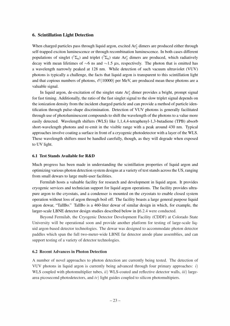
6.2.3 Progress Toward a Cryogenic LAPPD
A large-area picosecond photodetector (LAPPD) is a fast photodetector based on the microchannelplate (MCP) design [43]. LAPPDs have been deployed in a variety of high-energy physics exper-iments. They offer high spatial and temporal resolution, large geometric coverage, high quantumefficiency, and a low cost. These features make LAPPDs attractive for use in large area liquidargon photon detection applications. The LAPPD development group at Argonne National Labo-ratory (ANL) is instituting a systematic program of photocathode research and analysis with thegoal of operating LAPPDs in a cryogenic environment. They are currently studying a 6×6 cm2
design based on borosilicate glass capillary arrays made by Incom, Inc. and functionalized usingan industrial batch method of atomic layer deposition (ALD) is shown in Fig. 18. This combinationoffers a novel and inexpensive manufacturing method that allows for large formats, greater than 20cm2, and a tunable response.
Through fast and slow dunk tests in liquid nitrogen followed by vacuum tests, the group hasinvestigated the robustness of these LAPPDs at 87 K and found that both the indium seal on the
– 25 –
Figure 18. (left) A 6×6 cm2 “small tile” LAPPD and (right) exploded view of its components.
cathode and glass frit bond on the anode side remain intact after cryogenic cycling. The ANLgroup is also investigating the resistance of the MCP versus temperature in order to find the optimalALD recipe for cryogenic operation. Going forward, they plan to deploy a 6×6 cm2 LAPPD thathas been functionalized for cryogenic operation, along with appropriate readout electronics, intoa dewar with TPB-coated walls to study the response of the LAPPD to wavelength-shifted lightinduced by the liquid argon scintillation signal.
6.2.4 Light Guides for Large-Area Photon Detection
Large-area photon detector design based on acrylic light guides coupled to silicon photomultipliers(SiPM) are an attractive design for multi-kiloton scale detectors like LBNE. These unprecedentedlarge volumes present new challenges for the design of an affordable and effective photon detectionsystem. This system must provide event timing of better than 1 µs in order to determine eventpositions and correct track energy measured by the TPC. It must also provide an ability to triggeron non-beam events for investigations of proton decay and non-accelerator neutrinos. Furthermore,to be sensitive to supernova burst neutrino physics the photon detection system must also be ableto detect neutrinos with energies on the order of 10 MeV.
The LBNE collaboration is pursuing this option for photon detection. In the current baselinedesign, each photon detector module consists of four acrylic bars coated with a WLS which col-lects VUV scintillation photons and converts them to ∼430 nm. The photons propagate via totalinternal reflection to the ends of the bars. An array of three 6×6 mm SiPMs on each acrylic lightguide, with a peak response at 420 nm, detects the waveshifted light. This segmented design pro-vides some position-dependent response, helping to localize the trigger signal while maintaining alarge sensitive surface area with a low photocathode area. The basic design of one light guide isillustrated in Fig. 19.
A number of waveguide designs are currently being investigated by the LBNE collaboration.The base design is an acrylic bar of dimensions 50.8 cm × 2.54 cm × 0.6 cm with a surface coat ofWLS, either TPB or 1,4-bis-(o-methyl-styryl)-benzene (bis-MSB). Three methods of applying thesurface coat have been investigated: i) a design developed at Indiana University where a solutionof TPB or bis-MSB in methylene chloride is spray-painted onto an acrylic bar from a pressurizedvessel, after which the bar is flash-heated rapidly to melt a thin outer layer of acrylic; ii) a design
– 26 –

Figure 19. Illustration of a single light guide. A WLS-coated acrylic bar converts VUV scintillation photonsto visible and propagates them via total internal reflection to an array of SiPMs at the end.
developed at the Massachusetts Institute of Technology where a solution of TPB and acrylic dis-solved in toluene is applied to the surface of an acrylic bar by hand-painting; iii) another design bythe MIT group where an acrylic bar is dipped into this solution of TPB, acrylic, and toluene to leavea thin layer of acrylic with embedded TPB on the surface of the bar. In addition to these surface-coating methods, two commercial vendors have been contracted to produce acrylic or polystyrenebars with TPB or bis-MSB doped throughout the bulk of the plastic at a concentration of 1% duringthe polymer casting process.
Two additional module designs are also under development. Colorado State University usesthirty-two 3×3 cm2 polystyrene fibers doped with TPB to cover approximately the same activearea as four bar-based light guides. This design has the advantage of mapping four fibers at atime completely onto the surface of the 6×6 cm2 SiPM package, reducing the number of SiPMsrequired for the same geometric coverage. The group at Louisiana State University is developinga 20.3 cm-wide acrylic plate into which a Y11 WLS fiber has been embedded. The surface of thisplate is then coated in TPB so that the scintillation light is converted to 430 nm, then captured andconverted by the fiber and propagated to its ends. One SiPM is positioned at each end of the fiber,with the potential to further reduce the number of photodetectors required and provide a positionmeasurement based on the relative signal strength at each SiPM. Figure 20 shows the three optionsunder consideration for LBNE.
To facilitate acquisition of data from this SiPM-based photon detection system, a fast cus-tom readout system tailored to the output characteristics of SiPMs is being developed by theHigh-Energy Physics electronics group at ANL. The SiPM Signal Processor (SSP) features sin-gle photoelectron-capable resolution, a 14-bit dynamic range, timing resolution better than 5 ns, a13 µs data buffer to collect both the prompt and late signals, and highly configurable digital signalprocessing implemented in firmware. Four SSPs have been completed and deployed at institutesfor local testing of photon detector designs.
Design comparisons were carried out in tests at the TallBo facility at Fermilab. The cryostat islarge enough to accommodate up to sixteen different lightguide designs in an ultra high purity liquidargon environment. Tests of various coat thickness options of TPB and bis-MSB on flash-heatedacrylic bars have been performed, allowing for the identification of the optimum amount of eachwaveshifter for that design. Another set of tests compared several bar-based lightguide modulesand the polystyrene fiber design side by side. The comparison identified acrylic dip-coated withTPB, polystyrene doped with TPB, and one flash-heated bar coated with bis-MSB as the mostpromising designs. This run also deployed the SSP to read out one module, allowing a detailedanalysis of the time-resolved structure of the scintillation signal induced by cosmic-ray muons.
– 27 –

Figure 20. Examples of the three light guide-based designs under investigation for LBNE. From left to rightare acrylic bars coated with a WLS compound, TPB-doped polystyrene fibers, and a TPB-coated acrylicplate with imbedded WLS fiber.
6.3 Effects of Contaminants on Scintillation Light
While ultra-pure liquid argon features a long attenuation length at its scintillation wavelength,the presence of impurities can both reduce this attenuation length and quench the production ofscintillation light. Some of these impurities also impact electron lifetime in the electric field of theTPC. Contaminants are particularly difficult to remove when they are present in the source gas,similar in boiling point to liquid argon, or not removable by regenerable filtering techniques.
The particular composition of impurities depends on the source gas. Industrially-producedargon is collected from air, and typically includes some amount of nitrogen, oxygen, and water.Commercial ultra-high purity (UHP) argon is manufactured by industrial distillation followed bypurification with molecular sieves and filters. This method typically produces UHP liquid argonwith small residual nitrogen at the ppm level and oxygen at below ppb level concentrations. Argonsourced from CO2 contained in underground wells may lack the radioactive 39Ar isotope, makingit ideal for liquid argon-based dark matter applications. However, this underground-sourced argontypically contains additional residual helium, methane, and CO2 impurities.
Of these contaminants, nitrogen is a particularly difficult impurity to remove. While it isnot a concern for TPC performance, nitrogen both quenches the production of VUV scintillation
– 28 –

photons [44] and shortens their attenuation length [45, 46]. The absorption effect for meter-scaledetectors is significant at concentrations above 2 ppm. Furthermore, the presence of nitrogen abovethis level also shortens the mean lifetime of the triplet state, degrading a photon detector system’spulse-shape discrimination capability. Fortunately, typical industrially-sourced UHP argon con-tains sub-ppm concentrations of nitrogen. Careful procedures during filling and operation of thecryostat should be sufficient to maintain a pure liquid argon environment.
The quenching and absorption effects of methane on liquid argon scintillation light has recentlybeen studied along with a search for evidence of reemission in the visible spectrum [47]. Bothabsorption and quenching of the VUV signal from a polonium source in liquid argon was foundand was unaccompanied by any observed re-emission in visible wavelengths. For distances of O(10cm) absorption lengths of O(10−3)/ppb were found and absorption was shown to dominate overquenching. This result indicates the maximum residual methane concentration tolerable for liquidargon experiments dependent on photon detection which rely on underground-sourced argon.
Instead of being lost to a contaminant, the Ar∗2 excitation energy can also be deliberately trans-ferred to a dopant, which then decays by photon emission. A promising dopant for signal enhance-ment through this transfer mechanism is xenon. The photon emitted by an excited xenon atomhas a wavelength of 175 nm. This transfer could prove advantageous in certain photon detectionapplications because of the higher sensitivity of some TPB-based coatings to VUV photons of thatwavelength. At xenon concentrations between 100 ppm and 1000 ppm, a large fraction of the tripletstate Ar∗2 emission seems to be replaced by a signal at timescales of O(10 ns).
These two effects make xenon a candidate for moderate enhancement of photon detectionin liquid argon. However, xenon is an expensive element, making its deployment as a dopantat concentrations as low as 100 ppm in a large-volume LArTPC an expensive proposition. Thecurrent estimated budget for the LBNE far detector’s photon detection system is $10 million. Forcomparison, the cost of adding 10 ppm of xenon into the far detector cryostat is $5 million. Anadditional 50% photon detector coverage would provide a more substantial enhancement in lightcollection efficiency than the equivalent cost of xenon dopant. While further studies need to beconducted, current results seem to indicate that xenon doping does not produce a cost-effectiveenhancement of the scintillation yield [48].
6.4 Characterization of Silicon Photomultipliers for Photon Detection Systems
While operated at cryogenic temperatures, SiPMs offer several appealing features suitable for usein a photon detection system. The single-microcell response features a long exponential tail but asharp rising edge with a few nanosecond rise time. The amplitude of the prompt rising edge and theintegrated charge collected by the SiPM both exhibit a quantized and discrete integer photoelectronresponse, making measurement of the number of photons incident on the SiPM straightforward.Furthermore, the noise rate in the SiPM just above the breakdown voltage drops from several kHzto a few Hz at 87 K, meaning they can be operated with a bias voltage of a few tens of volts in aregime with simultaneously high gain and low noise.
The LBNE photon detector prototype test at the TallBo facility provided the first in-situ testof the SSP prototype photon detector readout electronics. The system operated with negligibleelectronics noise, similar gain to warm temperature operation, and reliable data quality. The single-photoelectron response of each SiPM was easily derived from in-situ data, and the time-resolved
– 29 –

structure of the scintillation signal from cosmic-ray muons was successfully measured with thissystem despite the 500 ns long exponential tail of the SiPM response. The discrete and quantizedresponse of SiPMs to incident photons at cryogenic temperatures makes signal calibration simple.
Lesson Learned SiPMs have been demonstrated to perform well in liquid argon and offerseveral appealing features including low noise, high gain, and fast timing.
6.5 Design Considerations from Physics and Engineering
6.5.1 Physics-Driven Design Requirements
The scintillation light in neutrino LArTPC detectors can be used to trigger detector readout, deter-mine the event start time (t0) for non-accelerator events, reject cosmic backgrounds, and supple-ment charge-based event reconstruction such as particle identification. The specific requirementsof a photon detection system vary between applications. For example, light collection systems playa pivotal role in rejecting cosmic backgrounds in surface LArTPCs. To do so requires the matchingof TPC tracks to light flashes reconstructed by the photon detection system. Therefore, it is notonly the amount of light collected but also the granularity of the photon detection system that mat-ters in order to localize the light signal. On the other hand, underground LArTPCs are sensitive tomore types of non-accelerator events, such as supernova neutrinos, which must be triggered. Here,some position resolution can be sacrificed in order to collect more light at a reduced cost. In bothcases it is important to collect enough light to determine the interaction time, t0.
6.5.2 Timing Resolution
The fundamental limit on the timing resolution of a liquid argon photon detection system is depen-dent on the arrival time of the first detected photon, typically less than the 6 ns mean lifetime ofthe singlet state scintillation component when many photons are detected. This fact presents thepotential for more sensitive measurements of event timing. The MiniBooNE experiment highlightsan opportunity for improved timing resolution. It has demonstrated the capability of resolvingthe radio frequency structure of the Fermilab Booster neutrino beam. Such a measurement mayprovide an important handle on background rejection and could be a key handle on light dark mat-ter searches. A nanosecond timing precision could also provide for other extended capabilitiesof a photon detection system, like enhanced cosmic background rejection or even separation ofCherenkov light from the liquid argon scintillation signal.
6.5.3 New Approaches to Geometric Coverage
The growing size of liquid argon-based particle detectors is driving photon detection systems to-ward larger geometric coverage. A variety of designs are being explored with the goal of mitigatingthe corresponding rise in cost. Interference with the TPC must be also minimized, requiring photondetection system designs that avoid both mechanical and electrical interference with TPC opera-tions.
The enhanced collection of scintillation photons using coated detector walls, described above,is a promising option for enhancing the collection of VUV photons using conventional detectorslike PMTs. The total number of VUV photons converted to visible is larger, potentially providingmore light to be collected by a traditional array of PMTs without a wavelength-shifting coating.
– 30 –

This method does present a possible loss of position resolution since photons arriving at the photo-cathodes directly from the source may be swamped by reflected light. Materials for the reflectivewalls must also be carefully chosen to avoid buildup of charge near the TPC.
The LBNE collaboration is testing another scalable design for a large-area photon detectionsystem, based on light guide paddles (§6.2.4). The entire paddle surface is sensitive to the VUVphotons while internally-conducted light is detected at the end of the paddle. Currently 50-cmpaddles are being tested, with the goal of exploring designs up to 2 meters in length. Readout isaccomplished by small-area SiPMs, helping to reduce the photocathode area and cost. This mod-ular design affords some degree of position resolution while providing large and scalable surfacearea coverage. The photon detector modules will be located outside the TPC drift field in the anodeplane assemblies, aided by the small physical profile of the SiPM detectors.
7. Calibration and Test Beams
Liquid argon calibration and test beam efforts are now better coordinated than in previous years.The common aim is to develop techniques and make measurements that will be useful in future liq-uid argon experiments, and to make this global knowledge base available to the wider community.The previous LArTPC R&D workshop summary [30] gave an overview of the main calibrationand test beam efforts ongoing in the liquid argon community. This section summarizes in moredetail the types of calibrations that will be done in MicroBooNE and LBNE, and gives an up-dated status and plans for test beam experiments such as CAPTAIN, LArIAT, and CERN WA105(LBNO-Demo).
7.1 Calibration
An overview of the MicroBooNE, CAPTAIN, LArIAT, and LBNE TPCs, readout electronics, andcryogenic systems were presented in the previous workshop summary [30]. Here we do not repeatthose details, but instead discuss the specifics of planned calibrations using these detectors.
Charged particles traveling through the argon lose energy by both ionization and by excita-tion, resulting in scintillation light. The ratio of the two is well understood, and depends on thestrength of the drift electric field. However, other factors in the detector environment, such as purityand temperature, can also affect the amount of charge and light collected by the detector readout.Calibration of this response is a crucial component to proper reconstruction and identification ofparticle tracks in LArTPCs.
7.1.1 Charge
The initial cloud of charge will disperse due to diffusion and some fraction of the charge will becaptured on impurities in the argon. Controlling the the purity, the temperature, and the drift fieldis an important initial step in maintaining accurate calibration of LArTPCs.
In MicroBooNE, there are three purity monitors and a gas analyzer to measure the levels ofoxygen, water, and nitrogen, the most relevant contaminants affecting the charge and scintillationlight detection. In addition, temperature probes will monitor the TPC and bulk liquid temperatures,and heaters have been installed on the outside of the cryostat for temperature control, to ensureuniformity of the argon temperature throughout the full volume of the TPC. Any distortion in the
– 31 –

Drift field • Field distortion can lead
to ‘bend’ tracks • Surface location leads to
abundance of ions drifting 105 slower than e-
• HV chain resistance misalignment
09/07/14 MicroBooNE Calibrations, T. Strauss 8
M. Lüthi, master thesis LHEP Bern, M. Schenk, master thesis LHEP Bern, LHEP paper in preparation Figure 21. For a uniform electric field (bottom left panel), ionization charges from a straight track aredrifted to the readout wire plane along the shortest path, resulting in a straight track read out in wire numbervs. time (top left panel). For a distorted electric field (bottom right panel), ionization charges from a straighttrack may be drifted along a less direct path to the readout wire plane, resulting in a track that appears curvedin the wire number vs. time view (top right panel).
drift electric field can lead to bent tracks; distortions may be due to space charge buildup of theslow-moving ions drifting opposite to the direction of the ionization electrons, or due to mismatchin the components of the field cage resistive divider chain.
Figure 21 demonstrates the effect of a distorted electric field. For a uniform electric field (bot-tom left panel) in detector coordinates of wire number (x-Detector) vs. drift distance (z-Detector),ionization charges from a straight track are drifted to the readout wire plane along the shortest path,resulting in a straight track read out in wire number vs. time (top left panel). For a distorted electricfield (bottom right panel), ionization charges from a straight track may be drifted along a less directpath to the readout wire plane, resulting in a track that appears curved in the wire number vs. timeview (top right panel).
In MicroBooNE, the uniformity of the electric field will be mapped using 266 nm UV laserssituated at each end of the TPC, shown in Fig. 22. The lasers ionize the argon along their paths,leaving trails of ionization charge that should be straight. Any distortion in the laser tracks canbe corrected back to straight lines, thus creating a calibration map to compensate for any inho-mogeneities in the electric field. The proof of principle was successfully demonstrated in AR-GONTUBE at LHEP Bern, presented in the previous workshop of this series. The design andimplementation of the fully-featured production system installed in MicroBooNE benefited from
– 32 –

Space charge - Drift field calibration with an UV laser
• Space charge will be present • A 266nm UV laser can be
used to ionize liquid argon • Send laser along different
paths to map the drift field from both detector ends
09/07/14 MicroBooNE Calibrations, T. Strauss 11
arXiv:1406.6400
x2
Figure 22. The MicroBooNE UV laser calibration system with steerable mirror, situated at each end of theTPC (only one end shown here).
the ARGONTUBE demonstration.LBNE also plans to have a UV laser calibration system. A small-scale prototype of this system
is being implemented in CAPTAIN (and Mini-CAPTAIN). It is similar to the MicroBooNE lasersystem, but with a simplified fixed-incidence-angle mirror design that is rotatable through a smallrange of azimuthal angles, as seen in Fig. 23. The CAPTAIN system will be used to validatethe LBNE optical feedthrough design and the rotary control and encoder systems. It will alsoprovide the opportunity to test proposed calibration concepts and to understand potential damageto the TPC. In view of future use in much larger detectors such as LBNE, this system will alsoverify whether the required pointing accuracy can be achieved of better than the wire spacing fordistances up to about 20 m, and whether the beam divergence can be kept small enough to be ableto ionize liquid at 30 m from the source.
Charge calibration is also necessary in the readout electronics for the induction and collectionplane wires. For each readout channel, MicroBooNE will measure the baseline, noise, crosstalk,gain, linearity, and signal shape/rising time. A calibration capacitor is incorporated into the coldelectronics ASIC front-end; injected calibration pulses will be used to characterize the cold ASICbehavior and the behavior of all downstream components, including cables, feedthroughs, warmelectronics, and digitization. This calibration scheme will also be used in CAPTAIN, which has theidentical cold electronics, readout electronics, and DAQ chain as MicroBooNE.
Finally, cosmic rays can also be used to perform a number of calibration studies. The averagereconstructed charge of the cosmic rays, which should be a Landau distribution, will be used tocharacterize the calorimetric reconstruction performance of LArTPCs. Additionally, Michel elec-trons from the decay of stopping cosmic muons have a very well-understood energy spectrum with
– 33 –

CAPTAIN Collaboration Meeting, Santa Fe NM July 2014 Fermilab Liquid Argon Workshop, July 2014
Mini-CAPTAIN• Simple design
• Limited flexibility
• Fixed mirrors
• Azimuthal rotation through small range
optical feedthroughs$
5
%
'(7$,/$6&$/(
'(7$,/%6&$/(
127(7+(5($5(7:2/$6(578%($66(0%/,(6:+(5(7+(',))(5(1&(%(7:((17+(7:2,67+(29(5$///(1*7+2),7(07+((9$&8$7('/$6(578%(0LQLFDSWDLQODVHUWXEH,6PP/21*(57+(6(&21'',))(51&(,67+(),;('$1*/()257+(0,5525
,7(0123$57180%(5
6+((7
47<
ODVHUWXEHOBRG
LQFKVSKLUHZLQGRZ&HUDPWHF:
PLQLFDSWDLQORZHUODVHUPLUURUDVV\(GPXQG89PLUURU
PLUURUWXEHFODPS
YFUPDOHJODQG
YFUIHPDOHQXW
GHJUHHPLUURUPRXQW
GHJUHHPLUURUPRXQW
5(9,6,216
5(9'(6&5,37,21
'$7($33529('
$83'$7(':,7+),;('$1*/(3/$7(6(;7(1'('78%(
:6
'&%$$ % & '
:(,*+7
PLQLFDSWDLQODVHUWXEH
0,;('
:$/7
&200(176
6+((72)
4$
0)*$335
(1*$335
&+(&.('
'5$:1
'$7(1$0(
',0(16,216$5(,1,1&+(672/(5$1&(681/(6663(&,),(')5$&7,21$/$1*8/$50$&+
%(1'7:23/$&('(&,0$/7+5((3/$&('(&,0$/
),1,6+
0$7(5,$/
5(9
%':*12
6,=(
6&$/(
368%$720,&3+<6,&6
/26$/$0261$7,21$//$%25$725</26$/$02610
48$17,7<5(48,5('
<$
$//',0(16,216,10,//,0(7(56
fixed mirror (45o & 52o)
evac
uate
d pi
pe (
85 c
m &
75
cm) vacuum fitting
sapp
hire
win
dow
s
6Figure 23. The prototype LBNE UV laser system installed in CAPTAIN.
a sharp cutoff just above 50 MeV; these can be used as a calibration source for both the TPC andthe light collection system in MicroBooNE and future LArTPC experiments.
7.1.2 Light
Since a large fraction of the energy deposited in the argon by charged particles will be in the formof scintillation light, it is desirable to collect as much of it as possible in order to perform accuratecalorimetric energy reconstruction. The prompt fraction of the light will also provide a t0 to markthe beginning of an event, which will be especially critical for non-beam analyses in LArTPCs.
The MicroBooNE optical system consists of 32 8-inch photomultiplier tubes (PMTs) and 4light-guide paddles. Before installation, a few of the PMTs were subjected to detailed character-ization of stability, linearity, and absolute collection efficiency, described further in [49]. Thelight-guide paddles are a candidate light collection detector for LBNE, installed as an R&D test inMicroBooNE.
Calibration of the light collection system in MicroBooNE will be achieved by pulsing a seriesof quartz optical fibers coupled to a 450 nm LED situated outside the cryostat, shown in Fig. 24. Anexternal pulse delivered simultaneously to all PMTs and light-guides via these optical fibers willenable routine gain and timing calibrations of the entire light collection system. Trigger efficienciesand readout deadtimes will also be characterized using this system.
In LArIAT, a reflector-based light collection system is being implemented. The system issimilar to that used in some dark matter experiments, but is a first for neutrino LArTPCs. Tomaximize the amount of light collected by the two PMTs and three SiPMs in the system, theinterior walls of the TPC are covered with a reflective film coated with wavelength-shifting TPB.The PMTs and SiPMs will observe the TPC volume through the wire planes to collect both directand reflected light, enhancing the overall collection efficiency. The setup is shown in Fig. 25.
– 34 –

Feed through
LED
Fiber
One fiber per PMT
Pulser
Figure 24. Representation of the MicroBooNE optical fiber calibration system.
FNAL 2014.07.08-09 Acciarri Roberto - FNAL - LAr TPC R&D Workshop 18
TPC Visibility MapTPC Visibility Map
Other Updates: Simulation Cryostat modifications inserted in Geant
MonteCarlo is based on ArgoNeut detector with updated geometry
Light collection system (PMTs+SiPM+TPB) fully simulated and tested
P. KryczynskiX Axis Voxel NumberX Axis Voxel Number
Z A
xis
Voxe
l Nu
mbe
r –
Bea
m d
irec
tion
Z A
xis
Voxe
l Nu
mbe
r –
Bea
m d
irec
tion
Cat
hod
e S
ide
Cat
hod
e S
ide
P. Kryczynski
Figure 25. 3D CAD model cutaway of LArIAT system with wavelength-shifter-lined TPC walls and PMTs(and SiPMs, not shown) viewing the interior volume.
Particle identification and calorimetry will benefit from the higher light yield, and new studies onmuon sign determination using scintillation light will also be possible.
7.2 Test Beams
Calibrations and detector characterizations that are made possible by operating LArTPCs in chargedand neutral particle test beams are another important facet of building the global knowledge basefor the wider LArTPC community. In this area, there are three main efforts: CAPTAIN, LArIAT,and LBNO-Demo (WA105).
CAPTAIN’s primary aim is to characterize LArTPC response to low energy neutrons. Asa first step, the CAPTAIN collaboration is building mini-CAPTAIN, a 400 kg TPC instrumented
– 35 –

FNAL 2014.07.08-09 Acciarri Roberto - FNAL - LAr TPC R&D Workshop 11
Tertiary Beam & Beam Detectors Layout
UpstreamUpstreamTOFTOF
WireWireChambersChambers
Target+CollimatorTarget+CollimatorBending MagnetsBending Magnets
DownstreamDownstreamTOFTOF
Halo VetoHalo Veto
Punchthrough Punchthrough VetoVeto
Cosmic Cosmic μμ Trigger Trigger
LArIATLArIATCryostatCryostat
Particle momentum range and sign Particle momentum range and sign @ TPC selected by tuning secondary @ TPC selected by tuning secondary
beam energy and dipole magnetic field beam energy and dipole magnetic field ((±± 0.35 T) 0.35 T)
For 3For 3··101055 80 GeV 80 GeV ππ+ + per spill on per spill on target expected 400 particles at target expected 400 particles at
cryostat / 70-80 after trigger cutscryostat / 70-80 after trigger cuts J. M. St. John
J. M. St. John
Figure 26. LArIAT tertiary beam configuration. Tunable secondary pion beam impinges on tertiary targetat left side of image. Exiting tertiary beam is collimated in direction of bending magnets. TOF and wirechambers tag particles entering the LArIAT cryostat, and veto counters enable tagging of particles outsidethe cryostat beam window (halo) or exiting particles (punchthrough).
with 1000 channels. This prototype device is currently under construction, and will run in a neutronbeamline at the Los Alamos Neutron Science WNR facility in 2015. Using time-of-flight upstreamand downstream scintillator paddles, a visible interaction in the LArTPC can be correlated witha neutron of specific kinetic energy. The collaboration plans to study neutron interactions on liq-uid argon in terms of topology, multiplicity and identity of visible particles in the final state, andkinematic properties. The focus will be on primary neutron interactions of known incident neutronenergy to create a catalog and a probability distribution of possible event topologies as a functionof incoming neutron energies. Ultimately, this catalog will be useful for identifying outgoing neu-trons in neutrino interactions, where the neutron energy can then be obtained by PDF, resulting inbetter reconstruction of incoming neutrino energy.
LArIAT’s focus is on charged particles in the energy range that will support MicroBooNE andLBNE, as described in detail in the previous workshop summary. New cold electronics have beenproduced using the BNL ASIC developed for MicroBooNE, and the TPC was assembled with newwire planes. Notably, after almost a decade of not operating, the MCenter beamline at the FermilabTest Beam Facility has been refurbished and the secondary beam is fully commissioned. Effortsare now on tuning the LArIAT tertiary beam, seen in Fig. 26, while commissioning the DAQ usingbeamline wire chambers and TOF paddles. An engineering run using all beam detectors began inSeptember 2014 and lasted through the Fermilab shutdown. The detector was installed in the beamenclosure during the Winter 2015 and the experiment will take data during Spring 2015.
CERN’s WA105 test beam experiment, also known as LBNO-Demo, is a dual-phase LArTPC.The drift electrons produced in the liquid phase are extracted from the liquid into the gas phasewith the help of an electric field. Two grids, situated just below and above the liquid level, definethe appropriate extraction field. The extracted charge is then amplified in the gas phase with aLarge Electron Multiplier (LEM). The concepts of dual-phase liquid argon LEM-TPC detectorshave been demonstrated previously in smaller prototypes [41, 50, 51, 52], and a full-scale darkmatter experiment using this technology, called ArDM, is currently running in the undergroundlaboratory in Canfranc, Spain [41].
The goal of LBNO-Demo is to demonstrate the scalability of these detectors. The designconsists of a 6×6×6 m3 (∼ 300-ton) dual-phase LAr LEM-TPC with 2D-collection readout an-
– 36 –

LArTPC14 – July 9 2014Lukas Epprecht
LBNO-DEMO (WA105)Configuration
• 6x6x6 m3 active volume
– Tank dimensions of the inner vessel: 8.1 x 8.1 x 8.1 m3
• Double Phase TPC with Charge Amplification and particle reconstruction
• 2D-collection Readout Anode
– Large are readout with minimized dead area
• Exposition to 1-20 GeV/c charged hadron beam
• Completely scalable design for detectors, bigger than 50kt!
• Use of membrane technology for cryostat (non evacuated vessel)
• HV of 300-600 kV
4
LBNO-DEMO compared to GLACIER 20kt
Figure 27. LBNO-Demo (WA105) LAr LEM-TPC detector in membrane cryostat.
ode. Its size will allow full containment of showers up to 10 GeV. The detector will be placedinside a non-evacuated membrane cryostat, and the experiment will be installed in a 1−20 GeV/ccharged hadron beam at CERN. Figure 27 shows a cutaway of the cryostat and LAr LEM-TPC.Test beam running will enable development of automatic event reconstruction, testing of neutralcurrent background rejection algorithms on νe-free events, measurement of charged pion and pro-ton cross sections on argon, and characterization of calorimetric performance. As an intermediatestep, a 3×1×1 m3 prototype is currently under construction, with a timescale of 2014-2015.
The test beam activity across the world has evolved over the past year into a multi-pronged pro-gram with complementary branches to address pertinent questions regarding LArTPC performanceand calibration. CAPTAIN will characterize LArTPC performance in a beam of low- and medium-energy neutrons (< 1 GeV) at the Los Alamos Neutron Science Center. Additional possibilitiesfor later running include studying low energy neutrino interactions (< 50 MeV) from a stoppedpion source, and higher energy neutrino interactions (3 − 9 GeV) in the NuMI neutrino beam.LArIAT will operate in a charged particle beam at Fermilab, collecting data in the ∼ 200 MeV to2 GeV range relevant to MicroBooNE and LBNE. Finally, LBNO-Demo will extend these studiesto higher energies in a charged particle beam at CERN, collecting data in the 1− 20 GeV range.The collection of these complementary datasets will provide invaluable input to future experimentsstudying long- and short-baseline neutrino oscillations, atmospheric neutrinos, and burst supernovaneutrinos.
– 37 –

8. Software
8.1 LArSoft: Simulation and Reconstruction Software
LArSoft [53] is a software suite for simulating, reconstructing, and analyzing data from LArTPCs.Its purpose is to collect tools and interfaces to external software packages that perform importantfunctions that are needed by all experimental groups. Currently ArgoNeuT, LArIAT, MicroBooNE,LBNE, and LAr1-ND are using LArSoft. LArSoft allows the sharing and re-use of liquid argonTPC code, and also reduces the setup and learning required to use the external software in a wayconsistent with the requirements of the experimental collaborations. An important example ofthis latter use is the interface to Geant4 [54], which in general requires a significant investment inthe time of physicists to define the detector geometry, to set up the appropriate physics processesto simulate, and to interface it to particle generators and to produce useful output. LArSoft hasa uniform interface to geometry specification via reading of a GDML file, and it manages theinstantiation of the geometry in Geant4. LArSoft contains interfaces to the CRY [55] cosmic-raygenerator, the GENIE [56] neutrino-nucleus generator, and also manages the detector response toeach Geant4 step. It also provides flexibility in terms of which event generators can be used throughthe support of a text based event generator that uses the StdHEP syntax for describing particles.
LArSoft is built on the art framework [57], which is developed and supported by Fermilab’sScientific Computing Division (SCD). The art framework drives the event loop, and steers theexecution of the various processing steps via configuration files. Event data are immutable andare stored in ROOT format. The framework provides I/O utilities for reading and storing dataproducts and tracking their history. There is also a feature-rich event display facility. LArSoft isalso supported by Fermilab’s Scientific Computing Division with regular input from experimentalstakeholders.
The LArSoft management team at Fermilab has been refactoring the code base, rationalizingthe configuration files, and optimizing the resource usage. Some data structures and algorithmicchoices that perform adequately for a small liquid argon TPC perform poorly when scaled up to avery large detector with hundreds of thousands of readout channels. Optimization of the memoryneeded to represent the geometry of the detector, as well as that required for the data and theCPU needed to process it has been a focus of the LArSoft management team. Not only must thesoftware be optimized for execution on available computing resources, but it must also meet therequirements of the experiments and be easy to understand and use.
Lessons Learned:
• Transitioning to using new tools takes time and effort, and requires effort both on the part ofthe code management and the experimental stakeholders.
• Interactions between stakeholders must also be carefully managed, with appropriate tools inorder to minimize the impact of disruptive changes from one area of developing software toanother while maximizing the transfer of desired changes.
• Liquid argon software is still in a formative stage, with large improvements in accuracy,speed, and usefulness possible; new developers can make significant contributions.
– 38 –

• A mixture of personnel is needed on a large software project – managers, librarians, stake-holders, and developers, and these categories must be staffed by students, postdocs, labora-tory staff, and faculty.
8.2 Simulation of Liquid Argon TPC’s
LArSoft provides a general interface to specifying a LArTPC detector geometry, though use-casespecific needs, such as multiplexing readout DAQ channels, or experiment-specific photon readout,must still be met with experiment-specific code.
Because ionizing particles in liquid argon generate tens of thousands of drifting electrons andscintillation photons per MeV of energy deposited, LArSoft is configured to handle the chargedrifting and photon propagation parametrically. All detector geometries are broken into volume el-ements, “voxels”, that force the Geant4 steps on the boundaries, in order to enforce a fine-grainedsimulation. The energy deposited in a voxel is then used to compute a number of electrons andphotons produced in that voxel, using either Birks’ Law [58] or the Modified Box Model [59], orNEST [60]. The NEST model has been tuned to available noble-liquid detector data, and simulatesthe statsitical anticorrelation between the electron and photon production. The drift velocity is pa-rameterized in terms of the argon temperature and the electric field, which is a constant in LArSoftfor the time being but models including space charge buildup are being developed. Timing offsetsbetween readout planes are configurable.
The attenuation due to electron lifetime is adjustable by a configuration parameter, as is thediffusion. The spreading of a cloud of drifting electrons impinging on the wires of the detectoris simulated numerically by sampling from a Gaussian distribution. The response of the wiresto drifting charge is simulated from a pre-parameterized function of time describing the impulseresponse of induction or collection-plane wires. Parameterizable noise is then added, and the dataproduct is ADC digits as a function of clock tick. LBNE also applies a zero-suppression algorithmwhich is lossy in that it suppresses ADC readings below a threshold, while MicroBooNE appliesthe lossless Huffman encoding.
Photons are produced in three possible modes: fast scintillation with a time constant of ≈6 ns, slow scintillation with a time constant of 1.6 µs, and Cherenkov emission. Photons undergoRayleigh scattering on their path through the liquid argon, and they may be absorbed or reflected onuninstrumented surfaces. Some wavelength shifter is typically necessary to detect these photons.LArSoft simulates nearly all of these processes but lacks a simulation of the wavelength shifter,and also lacks purity and electric-field-dependent quenching. Photons may be propagated usingGeant4, which provides our best model of the physical processes, but is very slow computationallygiven the tens of thousands of quanta per MeV deposited. Instead, a library is built which lists theprobabilities that a photon emitted at a point in space in the detector will be detected by a specifiedphoton detector, for example a PMT in the case of MicroBooNE, or a SiPM in the case of LBNE.
Simulations require significant amounts of careful work to be useful. Currently, as data fromoperating experiments are lacking to tune the simulations, authors must rely on test stand, proto-type, and older experimental data as a starting point. LArSoft makes it easy to share and incorporatesimulation ideas, though the detector-specific details and challenges will require a certain divisionof the code between shared and specific elements. Sometimes it is good to have separate versionsof routines that do the same thing for different detectors – e.g. the digitizaiton routine for the LBNE
– 39 –

35 ton prototype need not be identical to that of the far detector. MicroBooNE needs its own ver-sion as well which is protected from changes by other experimental collaborations’ software effortsto match simulations to data.
8.3 Signal Processing and Reconstruction
Ionization liberated by charged particles traveling through the TPC will drift along electric-fieldlines towards the finely segmented anode planes. Proper biasing of the voltages on the anodeplanes allows the ionization to drift through the first Induction layers before ultimately stoppingon one of the wires in the collection layer. The electrical current that is created in the wires ofthe TPC due to this drifting charge is the base signal that is used to study the interactions thatoccurred inside of the TPC. Simulating and analyzing the current in the TPC wires requires modelsof recombination, diffusion, the electric field in the anode region, and knowledge of the responseof the electronics connected to the wires. Each of these facets of signal development, with varyingdegrees of sophistication, are implemented in the LArSoft simulation package and can be tailoredto the specifications of a given LArTPC detector. Treatment of signal development will continueto be refined as new insights are gleaned from the current generation of LArTPC experiments.
Signal processing algorithms can be used to manipulate the data collected by the TPC, forexample allowing removal of potentially noisy regions of frequency space, or converting the in-duction plane signals from their inherent bipolar shape to a unipolar shape similar to those on thecollection plane. This shape conversion enables common hit-finding and reconstruction code torun on all LArTPC planes. The performance of reconstruction algorithms will depend on how thesignal processing scheme is optimized for these parameters. Signal processing algorithms shouldbe robust enough to handle even pathological signals, such as the example shown in Fig. 28.
LArTPC R&D 16
Wire number
Wire number
Dri
ft ti
me
(tic
ks)
Dri
ft ti
me
(tic
ks) ArgoNeuT Data
Collection plane
Induction plane
Drift time (ticks)
Reconstructed hits on Collection wire 142
Big signal
~no signal
50 cm
Figure 28. ArgoNeuT data event demonstrating complicated pulse shape when a track is approximatelytraveling towards a single wire.
Reconstruction algorithms in LArSoft are utilized to take the signals collected by the TPCand light-collection systems and use them to infer the properties of any particles present inside thedetector during operations. The reconstructed particles can be further analyzed to determine theflavor and kinematics of any neutrinos that interacted in the detector.
– 40 –

The prevailing philosophy of reconstruction in LArSoft is to have many different algorithmsthat each perform one specific task, also allowing for the option to have different algorithms thateach attempt to do the same task in a different manner. Objects produced by one algorithm canbe saved to the event record and used by downstream algorithms. The sequence of reconstructionmodules that run during a job are configurable by the user, as are parameter settings within thosemodules. Figure 29 is a simplified flow-chart of a typical LArSoft reconstruction job.Reconstruction chain
• Bruce has covered the signal shaping.
• I will focus on the rest of reconstruction chain
• Hit reco, clustering, track reco, shower reco, calorimetry and PID.
H. Greenlee, LArTPC13
4
Figure 29. Example flowchart of reconstruction modules in LArSoft.
The typical reconstruction job follows a “bottoms-up" approach that begins with isolating hitswithin individual wires, followed by combining proximal hits into clusters, and then combiningclusters from different views into three-dimensional track objects. Many variations on this ap-proach have been investigated, and the optimum approach will very likely depend on the analysisbeing pursued. Tracks formed using TPC data can be further analyzed for their calorimetric prop-erties, which is crucial information that is used to identify the track’s particle type and also toreconstruct the energy and flavor of neutrinos that interacted in the detector. Track informationcan also be combined with information from light-collection systems to help remove out-of-beamactivity.
In the past year many new reconstruction algorithms have been introduced into LArSoft, andemphasis has been placed on developing metrics to gauge the performance of individual reconstruc-tion methods. Though it is clear that LArTPC detectors offer exceptional capabilities for studyingneutrino physics, it is also clear that developing reconstruction software to take full advantage ofthe LArTPC technology is a major challenge. The challenge is intrinsic to the projections of imagesprovided by the detector, and converting this information into a fully formed three-dimensional pic-ture. As experiments get larger in size, and the electronics channel count grows from thousands tohundreds of thousands, software needs to be able to cope with the increased amounts of informationto handle. Many algorithms in LArSoft were found to scale poorly with channel count, and withincreased drift times, and so have been reformulated to work more efficiently. Code optimizationneeds to be constantly monitored as new software is developed.
9. World Wide R&D Efforts
As indicated in the preceding sections, the development of LArTPC technology is being pursuedactively throughout the world. The development is being carried on both at the level of individualinstitutions as well as through major research laboratories. In this section we highlight some of theefforts that have not already been mentioned in this document.
– 41 –

9.1 Development in Continental Europe
CERN is focusing on developing a Neutrino Platform to support development of neutrino detectors.Several aspects of this platform focus on LArTPC development. One aspect is the refurbishmentof the ICARUS T600, now known as WA104, in order to expose it to the Booster neutrino beamat Fermilab. Another aspect is the development of a dual phase LArTPC to be exposed in a testbeam, WA105, which was described in § 7. The WA105 effort may also include the exposureof a prototype of the LBNE detector to the test beam. As part of these efforts, CERN has beenpartnering with Fermilab to develop common solutions for the cryogenic systems needed to supportLArTPC experiments. The goal of developing these common solutions is to create standardizedcomponents of the cryogenic systems that can be replicated for a variety of experiments, includingLAr1-ND, WA104, and WA105. CERN has committed significant resources to these projects inorder to provide the necessary infrastructure for them by 2016, including the construction of a largeneutrino test area capable of delivering charged particle beams to these detectors.
The University of Bern in Switzerland had proposed a novel and modular approach for thedesign of large mass LArTPCs called ArgonCube, which also includes a significant set of R&Dstudies to create a next generation of detectors. This detector design is the result of the evolutionof the research program conducted over several years starting with the ArgonTube project. Theprogram also benefits from a series of notable contributions from other institutes, such as Fermilaband Brookhaven. The ArgonCube program aims at the construction and operation of a series ofdetectors of increasing dimensions and complexity. The ultimate goal of the program is a feasi-bility study of modular LArTPC detectors with masses up to several tens of kilotons. The centralidea is to construct and position identical and separate modules in a common bath of liquid ar-gon. Each module features a relatively short drift length and a fully independent TPC with its ownreadout, light detection system, cryogenics, and services. Module walls are made thin to providetransparency to electromagnetic and hadronic showers as well as to neutrino produced primaryparticles. This detector configuration should also allow the optimal use of the liquid argon with arelatively large fraction of active volume, as compared to other implementations of the technology.The short drift length will permit less stringent requirement on the liquid argon purity, hence al-lowing the concentration of development efforts on other topics, such as the development of novelpixel readout schemes instead of the traditional wire plane readout. In a pixel readout, a singlereadout electrode would be segmented into pixels of a size comparable to the wire spacing in thestandard approach. The number of pixels for equal spatial resolution will be two or three ordersof magnitude higher than the number of sense wires, with a corresponding increase of the numberof signal channels, data rates and power dissipation. This scaling would make such a solution un-tenable except for small detectors and a readout scheme that reduces these issues to a reasonablylow level must be found. Multi-prong development efforts will be an iterative process with mul-tiple phases of prototypes including cosmic rays and charged particle test beams, as well as dataanalysis to reach the optimum configurations. This group is implementing these plans in a three-phased approach that builds on their previous work and the lessons learned by the construction ofMicroBooNE and ArgoNeuT. Ultimately the goal is to produce a prototype that will be exposed toa charged particle beam at CERN and that can demonstrate the success of such a modular approach.
– 42 –

9.2 Development in the United Kingdom
Activity in development of liquid argon technology for neutrinos has ramped up significantly inrecent years in the UK, with at least 10 institutions now active. All these institutions are nowmembers of the LBNE and LAr1-ND projects at FNAL and some are participating in MicroBooNE.The UK funding agency, STFC, recently awarded construction resources for participation in LAr1-ND. The agency also supports engineering design and DAQ resource support for LBNE, includingfor participation in the 35 ton prototype at FNAL. Broadly a ’northern hub’ of institutes comprisingLancaster, Liverpool, Manchester and Sheffield plus UCL in London, have particular interest inhardware development. The Sheffield group pioneered early UK work on liquid argon technologyin the area of single phase readout concepts using light readout of thick GEMs. Liverpool hasrecently made major progress here, working with CCD readout and using both single and dualphase systems. They demonstrated CCD images of alpha tracks using secondary scintillation inliquid argon. Manchester has developed expertise in TPC wire technology through involvementin the SuperNEMO double beta decay experiment. This expertise is now being turned towardsparticipation in the LAr1-ND project; they are developing new wire winding robotics for LAr1-ND. For this work the three groups are together funded to build part or all of the anode plane andcathode plane assemblies (APA, CPA). The Lancaster group have developed a cryogenic testingfacility for these assemblies and UCL has taken its experience in the dark matter field to developHV feed throughs for LAr1-ND. Significant engineering R&D has also developed around all ofthis work, for instance at Sheffield new designs of APA frames have been established, built andtested. This work is feeding into new designs for the much larger LBNE far detector APAs andthe CERN platform program. The earlier work on CCD operation in liquid argon has also alloweddevelopment of a multi-camera array that is to be deployed inside the LBNE 35 ton prototype atFermilab for monitoring of potential HV corona. An important aspect of the UK efforts outsidedetector hardware has been development of DAQ systems by Oxford and RAL, with input alsofrom Sussex on event building. Oxford are taking a lead on DAQ for the LBNE 35 ton prototype.The remaining UK groups, particularly Cambridge and Warwick, are focussing mainly on eventreconstruction software.
10. Summary
The workshop successfully brought together experts from around the world to discuss the latestdevelopments toward the goal of producing multi-kiloton scale LArTPCs. The final session of theworkshop was a discussion of i) the development of stable high voltage delivery systems for longerdrift distances than currently achieved, ii) new directions in scintillation photon collection, and iii)the development of magnetized LArTPCs.
The high voltage delivery system development continues to challenge many experiments. Dur-ing the workshop, it was agreed that a more complete picture of the physics leading up to dischargesof high voltage systems needs to be much better understood. The geometry required for creating adischarge, as well as the precursors to a discharge need to be documented so that future experimentscan avoid designs that are susceptible to discharge. These studies are especially important whenpushing the limits of drift distance as the amount of high voltage delivered is directly proportional
– 43 –

to the drift distance. One may also ask whether it is necessary to push drift distances beyond thecurrent scale, a question that assumes a different approach to instrumenting the liquid argon vol-ume than having a single, monolithic volume. Even at smaller scales though, an experiment needsto have extremely high confidence that the high voltage delivery system will not discharge.
The discussion of scintillation photon collection focussed on the potential gains of addingdopants to the liquid argon to enhance light production at longer wavelengths and the possibil-ity of improving timing resolution of the light detectors. Adding a dopant such as xenon couldimprove the production of photons in wavelength regions better suited to the response of somewavelength shifting materials. Such dopants could also shorten the timescale associated with thelate light considerably. Both effects are described in § 6.3. Improving the timing resolution of thephoton detectors may give one access to the prompt Cherenkov light produced by charged parti-cles traversing the argon. That information could be incorporated into reconstruction algorithms tofurther enhance signal to background rejection for many analyses ranging from accelerator basedneutrino oscillation studies to searches for more exotic phenomena such as light dark matter parti-cles.
The desire of many researchers is to magnetize LArTPCs to provide both charge sign discrim-ination of charged particles as well as kinematic information about those particles. These featureswould certainly enhance searches for CP violation in the neutrino sector, as well as improve theprecision of the other neutrino oscillation parameters. Two potential methods for magnetizing thesedetectors are the use of a solenoid magnetic design or a super-conducting double-racetrack config-uration with super-conducting wire looped at the top and bottom of the cryostat. Both optionsrequire significant development of the systems and then studies of their performance. Couplinga magnetic field with the position resolution of LArTPCs would truly make LArTPCs the digitalanalog to the bubble chamber.
11. Acknowledgments
The speakers at this workshop represented many colleagues from both collaborations and localuniversity groups. The work they presented was supported by a variety of funding agencies. Thefollowing statements of acknowledgement were supplied by the speakers and have not been edited.
We thank the ICARUS collaboration for sharing their experiences and lessons learned in build-ing and operating the first large LArTPC. The High Energy Astrophysics Group at Indiana Uni-versity is supported by the U.S. Department of Energy Office of Science with grant DE-FG02-91ER40661 to Indiana University and LBNE project funding from Brookhaven National Labo-ratory with grant BNL 240296 to Indiana University. The LArIAT collaboration is supportedby the U.S. Department of Energy Office of Science and the National Science Foundation. TheCAPTAIN detector has been designed and is being built by the Physics and the Theory divisionsof Los Alamos National Laboratory under the auspices of the LDRD program. T. Strauss spokeon behalf of the Albert Einstein Center, Laboratory of High Energy Physics of the University ofBern. The MicroBooNE and LBNE collaborations have participated in the development of coldelectronics as supported by the U.S. Department of Energy Office of Science.
– 44 –

References
[1] https://indico.fnal.gov/conferenceDisplay.py?ovw=True&confId=8381.
[2] ArgoNeuT Collaboration, C. Anderson et al., First Measurements of Inclusive Muon NeutrinoCharged Current Differential Cross Sections on Argon, Phys.Rev.Lett. 108 (2012) 161802.
[3] M. Adamowski et al., The Liquid Argon Purity Demonstrator, JINST 9 (2014) P07005.
[4] At the time of this workshop, the long baseline neutrino experiment planned in the US was calledLBNE. It has since been renamed to DUNE, however we kept the name in this document consistentwith what was used at the time of the workshop.
[5] MicroBooNE Technical Design Reporthttp://www-microboone.fnal.gov/publications/TDRCD3.pdf.
[6] As of the time of submission for this document, the short baseline neutrino experiment planned in theUS called LAr1-ND changed its name to SBND. We kept the name in this document consistent withwhat was used at the time of the workshop.
[7] G. Carugno et al., Electron lifetime detector for liquid argon, Nucl. Instrum. Meth. A 292 (1990) 580.
[8] MicroBooNE Collaboration, R. Acciarri et al., Liquid Argon Dielectric Breakdown Studies with theMicroBooNE Purification System, JINST 9 (2014), no. 11 P11001.
[9] Sigma-Aldrich, P.O. Box 14508, St. Louis, MO 63178 USA.
[10] BASF Corp., 100 Park Avenue, Florham Park, NJ 07932 USA.
[11] Spectris plc, Heritage House, Church Road, Egham, TW20 9QD, United Kingdom.
[12] LDetek Inc., 271 Saint-Alphonse Sud, Thetford Mines, Quebec, Canada G6G 3V7.
[13] Tiger Optics LLC, 250 Titus Ave, Warrington, PA, 18976-2426.
[14] Information on catalysts provided by D. Artrip of Research Catalysts,http://www.catalyst-central.com.
[15] ICARUS Collaboration, S. Amerio et al., Design, construction and tests of the ICARUS T600detector, Nucl. Instrum. Meth. A527 (2004) 329.
[16] ArgoNeuT Collaboration, C. Anderson et al., The ArgoNeuT Detector in the NuMI Low-Energy beamline at Fermilab, JINST 7 (2012) P10019.
[17] D. W. Swan and T. J. Lewis, Influence of electrode surface conditions on the electrical strength ofliquified gases, J. Electrochem. Soc. 107 (1960) 180.
[18] D. W. Swan and T. J. Lewis, The influence of cathode and anode surfaces on the electric strength ofliquid argon, Proc. Phys. Soc. 78 (1961), no. 3 448.
[19] F. Bay et al., Evidence of electric breakdown induced by bubbles in liquid argon,arXiv:1401.2777.
[20] A. Blatter et al., Experimental study of electric breakdowns in liquid argon at centimeter scale, JINST9 (2014) P04006.
[21] M. Auger et al., A method to suppress dielectric breakdowns in liquid argon ionization detectors forcathode to ground distances of several millimeters, JINST 9 (2014) P07023.
[22] J. Gerhold, M. Hubmann, and E. Telser, Gap size effect on liquid helium breakdown, Cryogenics 34(1994), no. 7 579 – 586.
– 45 –

[23] J. Asaadi et al., Testing of High Voltage Surge Protection Devices for Use in Liquid Argon TPCDetectors, JINST 9 (2014) P09002.
[24] L. Bagby et al., Breakdown voltage of metal-oxide resistors in liquid argon, JINST 9 (2014), no. 11T11004.
[25] http://www.epcos.com/blob/174146/download/
5/ueberspannungsableiter-und-schaltfunkenstrecken.pdf.
[26] http://www.bourns.com/pdfs/bourns_gdt_whitepaper.pdf .
[27] T. K. Gupta, Application of zinc oxide varistors, Journal of the American Ceramic Society 73 (1990),no. 7 1817–1840.
[28] http://www.epcos.com/inf/100/ds/a71h45xx2590.pdf .
[29] http://industrial.panasonic.com/www-data/pdf/AWA0000/AWA0000CE2.pdf
.
[30] B. Baller et al., Liquid Argon Time Projection Chamber Research and Development in the UnitedStates, JINST 9 (2014) T05005.
[31] LBNE Collaboration, C. Adams et al., The Long-Baseline Neutrino Experiment: ExploringFundamental Symmetries of the Universe, arXiv:1307.7335.
[32] S. Li et al., LAr TPC Electronics CMOS Lifetime at 300K and 77K and Reliability under ThermalCycling, IEEE Trans. on Nucl. Sci. 60 (2013) 4737.
[33] LArIAT Collaboration, F. Cavanna et al., LArIAT: Liquid Argon In A Testbeam,arXiv:1406.5560.
[34] A. Ereditato et al., Design and operation of ARGONTUBE: a 5 m long drift liquid argon TPC, JINST8 (2013) P07002.
[35] CAPTAIN Collaboration, H. Berns et al., The CAPTAIN Detector and Physics Program,arXiv:1309.1740.
[36] J. R. Hoff et al., Lifetime Studies of 130 nm nMOS Transistors Intended for Long-Duration, CryogenicHigh-Energy Physics Experiments, IEEE Trans. on Nucl. Sci. 59 (2012) 1757.
[37] G. Wu et al., Degradations of Threshold Voltage, Mobility, and Drain Current and the Dependence onTransistor Geometry For Stressing at 77 K and 300 K, IEEE Trans. Devices and Materials Reliability14 (2014) 477.
[38] A. Norman et al., The NOvA Timing System: A system for synchronizing a long baseline neutrinoexperiment, Journal of Physics Conf. Ser. 396 (2012) 012034.
[39] ICARUS Collaboration, M. Antonello et al., The trigger system of the ICARUS experiment for theCNGS beam, JINST 9 (2014) P08003.
[40] WArP Collaboration, R. Brunetti et al., WArP liquid argon detector for dark matter survey, NewAstron.Rev. 49 (2005) 265–269.
[41] A. Badertscher et al., ArDM: first results from underground commissioning, JINST 8 (2013) C09005.
[42] DarkSide Collaboration, T. Alexander et al., DarkSide search for dark matter, JINST 8 (2013)C11021.
[43] LAPPD Collaboration, J.-F. Genat, Development of Large Area, Pico-second resolutionPhoto-Detectors and associated readout electronics, .
– 46 –
[44] WArP Collaboration, R. Acciarri et al., Effects of Nitrogen contamination in liquid Argon, JINST 5(2010) P06003.
[45] B. Jones et al., A Measurement of the Absorption of Liquid Argon Scintillation Light by DissolvedNitrogen at the Part-Per-Million Level, JINST 8 (2013) P07011.
[46] B. Jones et al., Erratum: A Measurement of the Absorption of Liquid Argon Scintillation Light byDissolved Nitrogen at the Part-Per-Million Level, JINST 8 (2013) P09001.
[47] B. Jones et al., The Effects of Dissolved Methane upon Liquid Argon Scintillation Light, JINST 8(2013) P12015.
[48] C. G. Wahl et al., Pulse-shape discrimination and energy resolution of a liquid-argon scintillator withxenon doping, JINST 9 (2014) P06013.
[49] T. Briese et al., Testing of Cryogenic Photomultiplier Tubes for the MicroBooNE Experiment, JINST 8(2013) T07005.
[50] A. Badertscher et al., First operation and drift field performance of a large area double phase LArElectron Multiplier Time Projection Chamber with an immersed Greinacher high-voltage multiplier,JINST 7 (2012) P08026.
[51] A. Badertscher et al., First operation of a double phase LAr Large Electron Multiplier TimeProjection Chamber with a 2D projective readout anode, Nucl. Instrum. Meth. A641 (2011) 48.
[52] A. Badertscher et al., First operation and performance of a 200 lt double phase LAr LEM-TPC with a40x76 cm2 readout, JINST 8 (2013) P04012.
[53] https://cdcvs.fnal.gov/redmine/projects/larsoftsvn/.
[54] S. Agostinelli et al., Geant4 – a simulation toolkit, Nucl.Instrum.Meth. A506 (2003) 250–303.
[55] C. Hagmann, D. Lange, J. Verbeke, D. Wright, “Cosmic-ray Shower Library (CRY),UCRL-TM-229453 (2012); http://cnr07.llnl.gov/simulation/main.html.
[56] C. Andreopoulos et al., The GENIE Neutrino Monte Carlo Generator, Nucl. Instrum. Meth. A614(2010) 87–104.
[57] https://web.fnal.gov/project/ArtDoc/Pages/home.aspx.
[58] J. B. Birks, Proc. Phys. Soc. A 64, 874 (1951); J. B. Birks, The Theory and Practice of ScintillationCounting, Pergamon, London (1964).; T. Doke et al., Nucl. Instrum. Methods A 269, 291 (1988).
[59] J. Thomas and D. A. Imel, Recombination of electron-ion pairs in liquid argon and liquid xenon,Phys. Rev. A 36 (1987) 614.
[60] M. Szydagis et al., NEST: A Comprehensive Model for Scintillation Yield in Liquid Xenon, JINST 6(2011) P10002.
– 47 –