Embed Size (px)
Citation preview
THURBER ENGINEERING LTD.
July 20, 2012 File: 14-214-2
Lidstone and Company! Barristers and SolicitorsSuite 1300- Sun Tower, 128 Pender Street WestVancouver! B.C. V6B 1R8
Attention: Don Lidstone. Q.C.
THE SHORES SUBDIVISION - PHASE IGEOTECHNICAL ASSESSMENT
Dear Don:
As requested, Thurber Engineering Ltd. (TEL) has completed a review of the sinkhole formedon June 1! 2012 and previously reported sinkholes, slope instability, springs and erosion withinThe Shores subdivision. This letter documents our observations and provides our commentsand recommendations.
This report is subject to the attached Statement of Limitations and Conditions.
1. INTRODUCTION
The site is a 28 lot residential development with a plan area of about 400 by 200 m, located onthe west side of the neighbourhood of West Porpoise Bay, in Sechelt, BC, The site is on thesouth shore of Sechelt Inlet at Snake Bay and extends westward from the intersection of GaleRoad North (L-100) and Crowston Road to Snake Bay Creek. The site was developed byConcordia Homes Ltd. (Concordia). Civil engineering for the development was provided byWeb Engineering Ltd. (Web) and geotechnical engineering by GeoTacTics Engineering Ltd.(later incorporated as GeoTacTics Media Engineering (2007) Ltd.). For discussion purposes,we have used the name GeoTacTics to refer to both companies.
We understand that a spring developed on Lot 3 on May 26, 2012, and that significant quantitiesof sand and silt were observed discharging from the spring at that time. On June 1, 2012, asinkhole collapse occurred on Seawatch Lane (L-200) adjacent to Lot 28 at about Sta. 5÷80.Until the sinkhole collapse occurred, no surface manifestation of the sinkhole was reported. Forpublic safety reasons, the District of Sechelt (DOS) has closed access to the lane and hasbackfilled the sinkhole with granular material. The DOS is conducting regular site inspectionsand is regularly topping up the sinkhole backfill as required.
Following the formation of the sinkhole, DOS retained TEL to provide geotechnical input onexisting geotechnical issues and provide an assessment of the risk of similar issues occurring inthe future. To aid our assessment and understanding of the site, DOS has provided us withavailable historical geotechnical information on the development, elevation contours from 2009bare earth LiDAR mapping and miscellaneous documents, drawings and photos as backgroundinformation for our review. The documents are summarized in Table 1.
900. 1281 West Georgia Street, Vancouver, BC V6E 3J7 T: 604 684 4384 F: 69/. 684 5124thurber.ca

THURBER
2. SITE DESCRIPTION
2.1 Surface Conditions
The site physiography is described concisely in the GeoTacTics reports and is not repeatedherein. In those reports, the overall development property is divided into 4 zones, namely theforeshore, the backshore marsh, the lower slope and the upper slope as shown on GeoTacTics’Dwg. No. 2 (attached) dated August 2004. Phase 1 of the development lies between theforeshore and the crest of the lower slope at about El. 50 m. GeoTacTics indicates that theoverall slope of Phase 1 dips down at about l5cfro m the horizontal to the north east. Phase 2,which has not yet been developed, is proposed on the upper slope zone. Building lots arelocated both below the L-100 line (the extension of Gale Avenue North) and between the L-100line and L-200 line (Seawatch Lane), which roughly follows the crest of the lower slope. Thereis a 15 m wide environmental setback along the shoreline which was intended to precludedevelopment on much of the foreshore marsh zone. Most of the trees have been removed fromthis zone since commencement of construction.
2.2 Subsurface Conditions
Based on information provided by GeoTacTics, we understand that the typical soil profile in thedevelopment area comprises (from top down) an upper zone of very dense, cobbly, glacial tilland marine silt layers underlain by a deposit of grey/brown, fine grained sand, underlain by firmto stiff marine silt with lenses of fine sand. Groundwater is believed to be perched on thesurface of the lower marine silt layer and results in springs occurring in the fine sand layerexiting the slope near the base of the lower slope and on the backshore marsh. GeoTacTics’Figure 3, showing a schematic section of the site geology, is attached.
At the time of our 2008 site reconnaissance to assess the rock stack retaining walls on behalf ofDOS, the grey/brown fine sand deposit was visible at the western end of the site and the lowermarine silt was exposed in the foundation excavation for Lot 15. The near-vertical excavatedfaces in the sand were dry. Seepage was observed from above and from sand lenses withinthe marine silt layer. There were no exposures of the glacial till deposit at the time of the 2008reconnaissance.
In 2012, the grey/brown fine sand deposit is still visible at the western end of the site above theL-200 alignment from the park dedication to south of about Lot 17.
2.3 Existing Geotechnical Issues
Review of GeoTacTics’ reports indicates that wet zones and multiple springs formed on the cutslopes during site preparation, releasing significant volumes of water and soil. Following theformation of the springs, sinkholes began to be observed upslope of the springs. Additionally,there have been several instances of slope instability during and after construction. Theseissues were ongoing throughout construction and are documented in the available geotechrtical
Client Ltdstone and Company, Sarristers and Solicitors Date July 20, 2012File No 14-214-2E-File. bdjtltrThe Shores Geotechnical Review dcc Page 2 of 22

information. An active sinkhole and seepage feature were observed during our 2012 sitereconnaissance and follow up site visits.
As described below, we believe that the springs and sinkholes are distinct manifestations of thesame geotechnical issue. Accordingly, any geotechnical investigation program and remediationor mitigation measure must consider the whole system of which they are parts to be successful.
3. PROGRAM OF WORK AND REVIEW
Our program of work carried out in preparation of this letter report includes the following:
1) A site reconnaissance and follow up visits,
2) Soil sampling for laboratory testing
3) Geophysical survey with ground penetrating radar
4) A land survey of the sinkhole, spring and other indicators of springs and sinkholes
5) Airphoto interpretation
6) Review of available geotechnical information
Our geotechnical engineering assessment and recommendations are based on ourinterpretation of the above information.
3.1 Site Reconnaissance and Follow-up Site Visits
3.1.1 Sta. 5+80, L-200 Sinkhole and Lot 3 Spring
A site reconnaissance was conducted by David Tara, P.Eng. of TEL on June 2, 2012. Mr. Tarawas accompanied by Mr. Phil Strain of DOS. The purpose of the reconnaissance was tovisually assess the sinkhole and spring, provide interim guidance for management of thesinkhole and determine if there were any immediate life safety issues. Follow up visualinspections were conducted by Mr. Tara on June 5, 15 and July 1, 2012.
At the time of our initial site visit on June 2, the sinkhole area had been cordoned off withbarriers. The hole in the asphalt was immediately adjacent to the south curb near Sta. 5+80(L-200) and measured about 1.2 by 2.4 m in plan. Below the asphalt, the opening was visuallyestimated to be about 4.6 by 4.6 m as shown in Photo 1.
Based on discussions with several of the residents, we were informed that the spring hadformed around midday on May 26. By mid-week, efforts were apparently made to contain the
OFent Lidstorie and company. Barristers and Sohoitors Date July 20, 2012Fle No 14-214-2B-File b,djt_ltrjbe Shores Geotechncal Review.doc
THURBER
Page 3 ot 22

THURBER
flow and direct it through a series of stilling basins to reduce the amount of silt and sand runningdown the bank and into Snake Bay.
The spring on Lot 3 is shown on Photo 2 and the first of the stilling basins (nearest to the spring)in Photo 3. As seen in the photo, the water is silt laden and the volume of flow is significant.
On June 2, we also observed that the water flowing in the ditch on the west side of CrowstonRoad disappears into the ground well upstream of the storm water culvert inlet.
It was agreed that DOS would conduct regular visual inspections of the site until the sinkholeissue was resolved.
On June 4 the sinkhole was backfilled by DOS with granular material.
At the time of our June 5 site visit, DOS staff had returned to remove a section of the curb andcomplete backfilling operations. The zone around the spring on Lot 3 had been reworked and19mm crushed gravel placed around the opening. As a result, the exiting water was muchmore dispersed with a significant component draining down the slope and the remainder into thestilling basins.
By June 6, DOS reported that a 1.2 by 2.4 m zone of the sinkhole backfill had dropped about0.5 m. Since that time, the backfill continues to disappear into the sinkhole and DOS continuesto regularly top it up. We understand that, initially, DOS was topping up the backfill with theequivalent of about 1 load of a single axle gravel truck per day but that the volume has sincedecreased.
We were informed by Mr. Ron Davis of Concordia that the Crowston Road ditch hasexperienced significant downcutting since it was constructed.
3.1.2 Slopes and Retaining Walls
In general, rock stack walls have been constructed to the south of Lots 19 to 21 and to the northof Lots 22 to 28. The transition from south to north occurs between Lots 21 and 22. The rockstack walls range from single to multi-tier with minimum tier heights of about 2 m. Other thanfencing on Lot 25, no safety rails or fences were observed.
The overall slope along the south side of Lots 19 to 21 dips down from Seawatch Lane at about28° to 30° from the horizontal. The majority of th e slope is supported by a system of rock stackwalls. However, in the southeast corner of Lot 211 a scarp-Hke feature is present as shown inthe oblique image (Photo 4) and 2009 airphoto (Photo 5) taken from Sunshine Coast RegionalDistrict (SCRD) Online Property Information System (OPlS).
The upper slope of Lot 18 dips down from the L-200 at about 38°to 40°from the horizontal.
Crent Lidstone and Company Barnsters and Solcitors Data Juty 20, 2012
‘eNc 14-212-2E-Ft a’ bcjtjtr_The Shores Gecteohn ca: Rev ew coo Page 2 of 22

SITHURBER
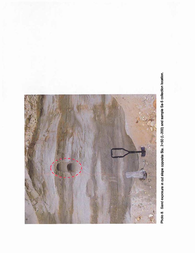
At the southwest corner of the site, the existing cut slopes are benched. Several of the cutslopes are near vertical as shown in Photos 6, 7, 8 and 9. No seepage was observed on thesoil exposures. No warning signs or hoarding are present.
The park dedication at the west end of the site appears to have been used as a spoil depositionarea. Locally, slopes dip down towards Snake Bay Creek at about 55°to the horizontal.
3.2 Soil Sampling and Laboratory Testing
During our June 15 visit, six soil samples were collected. Two samples of the sand depositeddownstream of the spring were collected (Sa-1 and Sa-2). Two samples of the sand exposureat the west end of the site were also collected near Sta. 2+40 of the L-200 alignment (Sa-3 andSa-4) at about 1 and 2 m above the curb or about El. 45.5 and 46.5 m (Photos 6 and 7). A sandsample was also collected opposite Sta. 2+50 (Sa-5) about 2 to 3 m below the original groundsurface as shown in Photos 7 and 8. Sa-6 was collected from the soil exposure south of Lot 17(about Sta. 3+40, L-200) as shown in Photo 9.
All six samples were submitted for routine classification and moisture content testing. Gradationanalyses were also conducted to evaluate the particle size distributions. The results are shownon Figures ito 6.
In general, material collected in the deposition zone below the outlet from the spring was fineroverall than any of the 3 sand samples collected at the west end of the site. Figure 7 shows all6 particle distributions and summarizes the pertinent gradation parameters. Based on thecoefficient of uniformity (Cu), all of the samples have a relatively uniform particle size and areclassified as poorly graded. The mean grain size (D50) was about 0.18mm in the depositionzone (Sa-1 and Sa-2) and ranged from about 0.25 to 0.41 mm in the undisturbed sand depositat the west end of the site (Sa-3 to Sa-5).
3.3 Ground Penetrating Radar Survey
A geophysical survey using ground penetrating radar (GPR) was undertaken by TerraprobeGeoscience Corp. (Terraprobe) on June Sand 6, 2012. The GPR survey was conducted alongthe Gale Avenue North (L-100) and Seawatch Lane (L-200) alignments, a limited portion ofCrowston Road and on portions of Lots 27 and 28. The results are presented in Terraprobe’sJune 20, 2012 report (attached). In general, the GPR survey identified several anomalies asshown on Terraprobe’s Figure 1 and our Dwg. 14-214-2-1.
3.4 Land Survey
DOS engaged John Theed Land Surveying Inc. (Theed) to conduct a survey of the locations ofthe sinkhole and spring, patches/repairs in the roadways. and where the water goesunderground in the Crowston Road ditch. A copy of their survey drawing dated June 12, 2012is attached for reference.
Client Licistone ano Company. Barristers and Solicitors Oate July20 2012File No 14-214-2E-FiFe b,.djtjtr_The Shores_Geotechriical Review dcc Page 5 of 22

THURBER
3.5 Airphoto Interpretation
We carried out airphoto interpretation of stereo pairs of photos borrowed from the University ofBritish Columbia for the years 1947, 1976, 1980, 1998 and 2003. DOS provided us singleimage digital files for March 2009 and 2012. We have acquired stereo pairs of digital imagesfrom Integrated Mapping Technologies for March 27 (SRS 7264-59 and -60) and April 5, 2006(SRS 7276-130 and -131) and have also reviewed images on Google Earth for November 1,2004, June 23, 2006, September11, 2009 and July 8, 2010.
The airphotos from 2003 and earlier were reviewed to assess the pre-development siteconditions. In all the images, gullies are visible along (i) Snake Bay Creek at the west end ofthe site. (H) near the centre of the development in line with Lots 10 and 19 and (Hi) at the eastend in line with Crowston Road. When comparing the airphotos, we note that the gulliesgenerally appear to become more distinct with time suggesting some on-going erosionalprocesses.
The 2004 Google Earth image shows the site prior to development in a state similar to the 2003airphotos.
The 2006 images are of the development early in the construction phase. The centre gully ispartially infilled and the L-100 and L-200 roads and some of the rock stack walls appear to beunder construction. Several sinkhole-like features are also visible in the image as shown onPhoto 10. A sedimentation basin is visible near the southeast corner of the site in the vicinity ofthe recent Sta. 5+80, L-200 sinkhole.
A portion of the March 2009 image provided by DOS is reproduced on Photo 11. The photoshows house foundations on Lots 13 to 15, largely completed houses on Lots 19 to 21, andcompleted houses on Lots 25 to 27. The scarp-like feature at the southeast corner of Lot 21 isclearly visible in the image. Scarp-like features and/or signs of recent instability are visible atthe south end of Lot 18 and the north end of Lots 25 and 26. Numerous erosion featuresincluding rills (surficial erosion patterns), localized gullying and springs are visible at severallocations including Lots 1 to 5/6, 9 to 12, 15, 16 to 18 and to the south of the Phase 1development. Significant ground disturbance is visible south of the Sta. 5÷80, L-200 sinkholeon the proposed Lot 29 (Phase 2) and behind Lots 23 to 26 as shown on the photo. A relativelysmall asphalt patch is visible adjacent to Lot 15.
The 2010 Google Earth image shows houses on Lots 19 to 21 and Lots 25 to 27 (Photo 12).House foundations are visible on Lots 13 to 15 and Lot 23. Springs or erosion features arevisible near the toe of the fill on Lots 2 and 4. The asphalt patch adjacent to Lot 15 is visible asis the ground disturbance behind Lots 23 to 26. The scarp-like feature on Lot 21 is visible.
A portion of the March 2012 image provided by DOS is reproduced as Photo 13. The photoshows largely completed houses on Lots 7 and 8, the same house foundations on Lots 13 to 15as seen on the 2009 image1 completed houses on Lots 19 to 21 and Lots 23 to 27. The
client Lidstone and company. Barristers and Solicitors Date. July 20, 2012File No 14-214-26-File. b_djt llr The Shores_Geotechnical Review doc Page 6 of 22

THURBER
scarp-like feature at the southeast corner of Lot 21 is still clearly visible in the image. While nosigns of recent instability are visible and vegetation has taken hold on most of the undevelopedlots, ercson features including rills, localized gullying and springs are visible at several locationsincluding the fill slope on Lots 1 to 6 and on Lots 9 to 12 as shown, Ground disturbance isvisible south of Lot 18 and behind Lots 23 to 26 as shown. Also visible are the majority of theasphalt patches and repairs shown on Theed’s drawing dated June 12, 2012. Of particularinterest is the patch adjacent to Lot 15 which appears to have quadrupled in size since the 2009image was taken.
3.6 Review of Available Geotechnical Information
In preparation of this letter, we were provided with the information listed in Table 1. Fordiscussion purposes. we will refer to the various documents by the issuer and date. Asdescribed below, geotechnical recommendations for design and construction of thedevelopment were documented in GeoTacTics reports dated September 30, 2004 and April 28,2006. GeoTacTics’ addendum to the April 28, 2006 report was issued on May 9, 2006 toaddress the issue of sinkholes that had developed during site grading work.
On behalf of DOS, TEL completed a geotechnical review of the stability of rock stack retainingwaIls adjacent to Lots 19 to 25 as documented in our report dated December 15, 2008. Our2008 review of the project relied on the above referenced reports to obtain an understanding ofthe site geology and construction history. No further geotechnical investigation was carried outas part of our 2008 review.
The documents described below include those that had information most relevant to developingour interpretation and recommendations.
3.6.1 Golder Associates Ltd. Study
May 1993 Report addressed to DOSThe May 1993 Golder study, completed as part of the Official Community Plan (OCP), classifiesthe site as Development Permit Area 5 (DPA 5), rocky beach front and upland slopes,Category b). natural hazard conditions. The report notes the following:
“The terrain within this Development Permit Area comprises predominantly steep rocky beachfront and upland slopes with a discontinuous surficial blanket or veneer of fine grained orgranular morainal soils or rubbly colluvium over bedrock. In the Snake Bay area, soils depositsare generally thicker and include a sand and gravel veneer of probable marine origin.
The soils are subject to potential shallow instability, small debris landslides and to minor stormwave erosion where they are exposed along the beach front. Creep and shallow instability in thesurficial soils were observed,”
Client Liostone ano Company, Barristers and Solicitors Gate July20 2012File No 14.214.2&-Frle’ bdjtltrThe Shores GeotechnicaF Review.doc Page 7 of 22

The Golder report also notes that:
“Surficial runoff and seepage from perched groundwater tables have contributed to theformat/on of gullies within the thicker surficial soil deposits/n these areas”
The Golder report indicates that, prior to the issuance of a development permit, the potential forslope instability and the impact of the development should be addressed by a registeredprofessional with specific experience in geotechnical engineering and/or engineering geology.The Golder report also provides guidance with respect to geotechnical issues to be addressedincluding cut and fill stability, instability caused by groundwater seepage, erosion potential dueto waves or drainage flows, setback zones, vegetation protection, etc.
3.6.2 Terra Engineering Ltd. Studies
Copies of a Terra Engineering Ltd. (Terra) letter dated October 24, 1988 for the Norbert CraftSubdivision which included the subject property, an appendix dated March 6. 1989 for theSechelt/Snake Bay Retirement Development and a July 23. 1992 report for a proposedresidential subdivision at the north end of Snake Bay Road were provided for our review. Oneof the most significant findings of the Terra documents was that several test pits encountered‘sands in a wet state which resulted in sloughing of’ the test pit walls. Terra also noted that“these wet sands, if exposed, would be very unstable and subject to undermining if left open”and that they are located “in the area of Snake Bay Road down through the proposed Hotelarea to the waters edge.” Terra generally noted that “the majority of the site has good bearingfor single family residential type structures” and that “ground slopes can generally be consideredstable”. Terra provided some preliminary recommendations with regards to cut and fill slopesand indicated that “proper ground slope protection will be required to protect all newly createdslopes from surface erosion and washouts”.
3.6.3 Geotek Designs
Copies of a Geotek Designs (Geotek) letters dated October31 and December 2, 1997 for thesubject property were provided for our review. The letters were addressed to Sea ShoresDevelopment Corp. The two letters are generally very similar in content. One change regardingthe waterfront lots relates to driveway grades wherein the maximum decreases from 20% to15% from October to December. The other significant change is in the December versionwherein Geotek added a “conclusion” section. In this section, Geotek concluded that “the nativesoils and natural slopes of the proposed phase 4 development are presently in a highly stableconfiguration. There are no indications of any threat of landslide.” Geotek also states that “theland can safely be used for the use intended.”
er L;dsone ac Co-npaly Barns!ers and So otors Dee J.’y 20. 2012Pie No: 4-2’42EFe bdttitrTbe Shores Geotechnical Review doc
THURBER
Page 8 of 22

THURBER
36.4 GeoTacTics Correspondence
September 30, 2004 Report addressed to ConcordiaThis report presents the results of a site reconnaissance and a preliminary geotechnicalassessment for the subject site and provides geotechnical recommendations for sitedevelopment. The report describes the site conditions in detail including the presence of thesprings on the Lower Slope. GeoTacTics notes that the Lower Slope is experiencing on-goinggradual erosion of the surficial soil and localized shallow sloughing of steeper pitches. Theaverage rate of retreat of the existing slope is estimated to be less than 10 mm per year and it isnoted that this rate would be expected to increase due to increases in rainfall and/or removal ofvegetation cover. The report notes that “slope retreat during a reasonable service life (60 to80 years) of a residential structure would be unlikely to encroach more than I m into the setbackzone.” The report also recommends no tree cutting or clearing in the shoreline environmentalcovenant areas.
The report recommends that site specific measures “should be implemented to deal with theactive spring areas on the Lower Slope” and provides preliminary guidance regarding suchmeasures. Finally, the report indicates that, provided the geotechnical recommendations arefollowed, “the property can be subdivided and safely used for the intended purposes.”
July 27, 2005 Memorandum addressed to ConcordiaThe memorandum describes a July 22 site visit during which heavy seepage was observedexiting the slope along the L-200 (between Sta. 1+20 and 1+50) and associated slope instabilityon Lot 15. The memorandum also indicates that, west of about Lot 25 (Sta. 2+00), activeseepage occurs along the L-100 alignment and that a number of drainage courses havedeveloped that carry the seepage across the alignment.
July 31, 2005 Memorandum addressed to ConcordiaThe memorandum describes a July 27 site visit. The memorandum is silent on seepage andslope instability issues.
August 12, 2005 Memorandum addressed to ConcordiaThe memorandum describes July 31, August 7 and 11 site visits and several on-going issuesincluding a sinkhole that developed at about Sta. 5+20 on the L-200. The sinkhole diameterwas apparently about 20 feet (6 m) and was reported to have been excavated out to a depth of18 feet (5.5 m). We believe that this is likely the sinkhole labelled “E” on GeoTacTics’ Figure 2(attached) of their April 2006 report.
August 27, 2005 Memorandum addressed to ConcordiaThis memorandum describes an August25 site visit and the repairs of the sinkhole at Sta. 5+20of the L-200 which included placement of a layer of mass concrete at the base and placement ofcompacted “glacio-marine sediments” above.
orient: Lidstone and company, Barristers and SoUcitors Date July 20, 2012File No.: 14.214.2FFiIe bdjtltrThe Shores_Geotechnical Review.doc Page 9 of 22

THURBER
The memorandum describes on-going challenges and recommends placement of a 3 inch(75 mm) minus rock drainage blanket beneath the round-about area as per Sketch P25-2(attached).
September 17. 2005 Memoranda addressed to Concord/aOne of the two memoranda dated September 17 describes a September 8 site visit and notesthat, as the recommended 3 inch minus rock for the drainage blanket was no longer available,3/4 inch (19 mm) clear crush gravel could be substituted. It also notes that new areas ofseepage have been encountered near Sta. 2+60 of the L-200.
The second memorandum describes the results of a September 15 site visit and a section of theslope above Sta. 2+60 of the L-100 that had slid, The slide was about 20 m in length. Thespring at the toe of the slope was reported to have a flow of 100 to 150 gpm. The memorandumprovides guidance for removal of the slide debris and recommendations for controlling thespring using filter fabric and clear crushed gravel.
September 26, 2005 Memorandum addressed to Concord/aThe memorandum describes a September 25 site visit. The memorandum is silent on seepageand slope instability issues.
October 5, 2005 Memorandum addressed to Concord/aThis memorandum describes a September 30 site visit conducted in the company of MahmoudMahmoud, P.Eng. of Global Earth Solutions Geotech Inc. (GES). Reference is made to a GESsite reconnaissance report but no copy was provided for our review. The purpose of the visitwas to assess tension cracks observed at Sta. 4÷40 of the L-200 and about 40-50 m long onSeptember28 and provide recommendations to address the very large groundwater flows at thetoe of the slope.
The memorandum also describes the large spring at Sta. 3+00 of the L-100 with an estimatedflow of about 200 gpm and indicates that the volume of sand being washed out had increasedsubstantially since formation to the equivalent of about 70 m3 per day.
This memorandum provides recommendations to address the spring and comprised extending abuttress and filter at least 10 m along the toe of the slope at this location and across the entirewidth of the road. The buttress and filter is described as a layer of geogrid placed on native soil.covered with layers of granular fill with nominal particle sizes ranging from 19 mm to 300 mm.Recommendations were provided to extend this buttress and filter to new areas as springsdevelop. The memo also provides recommendations for a drainage blanket to be constructedacross the full width of the road so that the water can be collected and conveyed from the springto the beach.
Client Lrdstone and Company, Barristers arid Solicitors Date July 20. 2012File No 14-214-2B-File bd1tltrTtie Shores Geotechnical Review dcc Page 10 of 22
THURBER
October 7, 2005 Memorandum addressed to Concord/aThis memorandum describes October 4 and 7 site visits. The memorandum notes that thetension crack described in the previous memorandum had not significantly changed except thattwo sinkholes had developed along the tension crack at the L-200 level, one at the crest and theother just below. The location’s were not specified by GeoTacTics and are therefore not shownon our drawing. It is inferred that these sinkholes were above the Sta. 3+00 spring on theL-100.
Two other sinkholes were reported. One was on the west site of the drainage course at the eastend of the property and the other near Sta. 2+10 of the L-100. We believe that these two areshown on GeoTacTics’ Figure 2,
October 10, 2005 Letter addressed to Concord/aThis letter was prepared in response to an August 30, 2005 letter from DOS and includes theJuly 27 to October 7, 2005 memoranda.
April 28, 2Q06 Report (including April 30, 2006 Cover Letter) addressed to Concord/aThis report includes test pits from a February 17, 2005 investigation report and provides anupdated estimated average rate of recession of 6 to 12 inches per year. The report alsodescribes the slope instability, springs and sinkholes and provides geotechnicalrecommendations for site development and a supplementary investigation. Figure 2 of thereport shows the geology and approximate locations of 8 sinkholes.
The report indicates that further geotechnical investigation is contemplated and indicates thatpiezometers will be installed.
The report concludes that “provided the site preparation, earthworks and foundationconstruction follow the genera! guidelines outlined above, the property can be safely used forthe intended purposes.” The report also notes that “residences constructed in this subdivisionare expected to be safe against reasonably conceivable geotechnical hazards, including slopeinstability, erosion and flooding” and that “the probability of occurrence of geotechnical hazardsis estimated to be less than 10 percent in 50 years”.
May 9. 2005 Letter addressed to Concord/aThis letter was issued as an addendum to the April 28 report to address the issue of sinkholes.The letter indicates that the majority of the erosion cavities occur in the fine sand layer cappedby glacial till and that the sinkholes have varied in diameter from 100 mm to greater than 6 m.GeoTacTics describes methods used to deal with sinkholes wherein the first involvesexcavation and removal of the entire sinkhole and the second involves cleaning the debris out ofthe sinkhole to expose the neck at the base followed by placement of mass concrete and thencompacted fill. This method is referred to as “plugging the neck’. The letter indicates that bothmethods will continue to be used where sinkholes are encountered. From this we infer that bothmethods have been used on the site to remediate sinkholes.
Client Lidstone and Company, Banisters and Solicitors Date July20 2012File No 14-214-2E-FiIe bdjtltrme Shores_Geotechnical Review dcc Page Ii o( 22

THURBER
June 1, 2007 Memorandum addressed to Concord/aThis memorandum describes a June 1 site visit and the challenges faced with controlling aspring along the storm outfall corridor between Lots 9 and 10.
August 31, 2007 Letter addressed to ConcordiaThis letter describes site visits of July 5. 18, 23, August 2, 3. 16 and 24. In the July inspectionsummary section. the letter describes control of a significant spring on Lot 5 and a sinkhole thathad developed in early June on Lot 29 of the future Phase 2 development. The letter notes that.on July 18. the sinkhole was 35 to 40 feet (11 to 12 m) in diameter and that it had subsided by 6to 8 feet (1.8 to 2.4 m) at its centre. The letter indicates that, on July 23, GeoTacTics observedthe excavation, plugging and filling of the sinkhole. The final extent of the excavated area wasapproximately 10.5 m deep and 12 m in diameter. The letter indicates that “the neck at thebase of the sinkhole, approxImately 1.5 m south of the edge of the L-200, was plugged byplacing several large boulders to create a bridge over the neck of the sinkhole and that theboulders were then capped with about 10 m3 of concrete and backfilled with native glacial till.”The letter also notes that the sinkhole was backfilled to the same elevation as the curb.
In the August inspection summary section, the letter notes deficiencies in the construction ofstacked rock retaining walls adjacent to the L-100 along Lots 24 through 27.
September 5, 2007 Fax addressed to ConcordiaThis fax describes an August 21 site visit for the Lot 26 garage foundations.
November 6, 2007 Faxes addressed to ConcordiaThese three faxes describe October25 and November 6 site visits for the Lots 19, 20 and 21foundation excavations.
January 17, 2009 Fax addressed to ConcordiaThis fax describes a January 14 site visit and several slides on Lot 25 and instability at the southend of Lot 18. Recommendations for mitigation measures were provided.
February 17. 2009 Letter addressed to DOSThis letter is written in response to Urban Systems’ March 3. 2006 memorandum. The letteraddresses geotechnical issues regarding site services. In particular, it notes that the drainageblanket has been placed on Lots 3 to 5 and Lots 9 to 12. The letter also describes the cause ofinstability of stockpiled fill on Lots 1 and 2.
February 25, 2009 Letter addressed to ConcordiaThis letter describes slope instability issues on Lots 1, 9 and 10.
March 7. 2009 addressed to ConcordiaThis letter provides recommendations for lot grading for Lots ito 12.
Orient Lidstone and Company, Banisters and Solicitors Date Juty 20. 2012File Nc 14-214-2E-Fite bdjtftrThe Shores Geotechnical Review dcc Page 12 of 22

THURBER
June 11, 2009 Fax addressed to Concord/aThis fax describes a June 10 site visit and the progress of site grading on Lots ito 12.
June 17, 2009 Fax addressed to Concord/aThis fax describes June 10, 12 and 16 site visits and the progress of site grading on Lots ito 12and Lots 16 to 18. The fax also expresses concern regarding potential instability issues at Lots18/19 and 21/22. Buttressing and flattening are recommended for Lots 18/19. The fax indicatesthat the stacked rock retaining wall was never completed in the southeast corner of Lot 21 andrecommends, at a minimum, temporary buttressing and flattening of the unprotected area.
June 24, 2009 Fax addressed to WebThis fax describes June 16, 18 and 23 site visits and the progress of site grading on Lots 1 to12. The fax notes that “site grading has satisfactorily buttressed the slope on the northern sideof the L-100, and there is no risk of catastrophic undermining of the road and the servicesburied beneath the road’ adjacent to Lots 3 to 12.
July 21, 2009 Fax addressed to WebThis fax describes July 16 and 21, 2009 site visits and the progress of site grading on Lots ito12 and Lots 16 to 18. The fax notes that “site grading has satisfactorily buttressed the slopa onthe northern side of the L- 100, and there is no risk of catastrophic undermining of the road andthe services buried beneath the road’ adjacent to Lots ito 12. The fax also notes that “Lots 16to 16 have been filled to the final lines and grades required to leave the lots in amaintenance-free condition until construction on the individual lots begins.”
December 18, 2009 Letter addressed to DOSThis letter describes the stack rock retaining walls on Lots 19 to 24 and provides as-builtsketches. In the first paragraph of the second page, the letter notes that Figures 3 to 8 “showthe proposed plan layouts of the stacked rock retaining walls on each of the respectivelocations and the as-built locations of the various tiers of stacked rock wall.” GeoTacTics’ third,fourth and fifth paragraphs and Figures 5 and 6 suggest that the rock stack walls were actuallycompleted on Lots 21 and 22. This does not seem to be consistent with our observations onsite or review of airphotos (see our Figures 11, 12 and 13) and should be clarified withGeoTacTics.
February 2, 2010 Letter addressed to DOSThis letter confirms that temporary site grading of Lots ito 18 has been completed in generalaccordance with GeoTacTics’ recommendations and notes that “there is minimal risk ofcatastrophic undermining of the L-100 and L-200 roads and the services buried beneath theroads.”
Chenit Lidstone and Company, Barristers arid Solicitors Date July 20, 2012File No.: 14-214-2E-File b_djt_Itr_The Shores_Geotechnical Review.doc Page l3of 22

THURBER
September 27, 2011 Letter addressed to ConcordiaThis letter describes a September 15, 2011 site visit to review the temporary excavated slope atthe southwest corner of the development. The letter notes that ‘no deep-seated instability hasoccurred in the slope since the slope has been excavated’. The letter concludes that the‘overall stability of the excavated slope is satisfactory” but that fragments of rock, gravel andsand will continue to fall and/or roll down”. For the temporary configuration, GeoTacTicsrecommends trimming the upper 0.6 m of the slope and vegetating other areas. For permanentslopes, GeoTacTics recommended flattening slopes to 2H:1V or flatter.
June 5, 2012 Fax addressed to DOSThis fax describes a sinkhole that appeared near the curb near Lot 9 (approximately Sta. 3+10).
3.6,5 Metro Testing Laboratories Inc.
Results of field density, concrete and gradation tests were provided. The August 15, 2007 fielddensity report (attached) provides test results and a sketch for the Lot 29 remediation whichsuggests that the edge of the sinkhole was at least 10 m from the east property line of Lot 29.
A number of field density reports include a marked-up copy of a sediment control plan preparedby GeoTacTics. A copy of Metro’s September 24, 2007 Field Density Report is attached. Theplan shows a sedimentation basin near the intersection of Seawatch Lane and Crowston Road.
3.6.6 Sunco Civil Consulting Ltd.
Limited results of field density tests were provided.
3.6.7 Web Engineering Ltd.
Drawings, letters, faxes and memoranda were provided. Two memoranda dated June 8, 2007addressed to N & B Contracting and Concordia make note of “a sinkhole developing aboveL-200 road’. We infer that this is likely the Lot 29 sinkhole shown in Metro’s field density reportand described in GeoTacTic’s August 31, 2007 letter.
4. ENGINEERING ASSESSMENT
4.1 General
The development has experienced many geotechnical challenges in the form of springs, erosioncavities and sinkholes, slope instability and surface erosion since commencement ofconstruction. In particular, previous reports by others, as well as early reports by GeoTacTics,identified groundwater and the risk of problems where the sand is encountered below thegroundwater table. Below we provide our assessment of the sinkholes and other geotechnicalissues.
CI,erit Lidstone and Company, Barristers and Solicitors Date July 20. 2012File No 14.214.2E-File bdjtltr The Shores Geotechiiical Review doe Page 14 of 22

THURBER
4.2 General Geological Processes
42.1 Geological Process
The sinkholes generally appear to be related to springs and subsurface erosion of the sand atthis site. Springs! cavities and sinkholes are the result of the same geological process and mayalso lead to surface erosion and slope instability. Cavities and sinkholes can be formed eitherdue to piping or internal erosion.
The piping process starts when water exits the ground with sufficient energy (hydraulic gradient)to erode the soil at the ground surface. This erosion of soil at the surface decreases the lengthof the seepage path thus increasing the hydraulic gradient. This results in a continuousretrogressive process of erosion at the exposed face. In some instances, the erosion can causea distinct cavity or pipe. Once initiated, the cavity or pipe concentrates the flow and seepagewhich, in turn, causes the length of the cavity or pipe to increase with ever increasing flows. Asdescribed by Terzaghi, Peck and Mesri (1996), “if a spring is powerful enough to start erosion inthe first place, the erosion will almost certainly become more ser/ous as time goes on, becausethe flow from a given spring increases with the length of the eroded tunnel.” The piping processonly stops when the hydraulic gradient falls to a low enough level. Piping is evident where thedischarge from springs contains silt and sand, and often may be turbid or muddy.
If the pipes are sufficiently shallow and large enough, a sinkhole or sinkholes may form at theground surface when the pipe cavity collapses. This only fills the pipe cavity in the area of thecollapse and the pipe remains open elsewhere. The open pipe may still be susceptible tocollapse resulting in the formation of other sinkholes. The pipe also remains a preferential flowpath and may be the parent of other pipes.
To prevent piping, properly engineered filters can be constructed to prevent soil erosion wherethe water is exiting, or has the potential to exit, the ground. Alternatively, the hydraulic gradientscan be lowered by installing wells or other dewatering measures.
Conversely, sinkholes may also form as a result of internal erosion wherein only the smallestsoil particles are eroded from the soil matrix. Internal erosion generally occurs in soil with awide gradation or a gap gradation wherein the smallest particles of soil can be transported bywater flow past larger particles. Internal erosion is typically a problem in man-made,manufactured soils and mechanically placed soils where segregation can occur. Uniform soils.such as typical beach sand, are not susceptible to internal erosion.
Springs will also contribute to surface erosion leading to slope instability resulting from highgroundwater lev&s associated with the springs, and unstable ground due to the formation ofunderground cavities and sinkhoies.
ClienI Lidstone ann Company, Bamsters ann Soi’citors Date July 20. 2012File No 14.214.2E.FiIe bdjtltr The Shores Geolechnical Review doe Page iSo! 22

THURBER
4.3 Specific Geotechnical Issues
4.3.1 Spring Locations
The approximate locations of several springs are shown on GeoTacTics’ Figure 2 and our Dwg.14-214-2-1. GeoTacTics reported significant springs on Lots 5 and Lots 9/10, at Sta. 2+60 and3+100 of the L-100 alignment and between Sta. 1+20 and 1+50 of the L+200 alignment.Significant seepage was also noted west of about Lot 24 or Sta. 2+00 of the L-100 alignment.4.3.2 Internal Erosion
We have assessed the potential for internal erosion (the potential for soil particles to move pastone another) of the recently collected soil samples. Using the criteria described in Terzaghi etal. and Kenney and Lau (1985), all of the samples collected are not considered susceptible tointernal erosion. Intuitively we feel that this is reasonable finding given the depositional natureof the deposits and that the materials are relatively uniform.
4.3.3 Erosion Potential of the Sand
The results of TEL’s gradation testing indicate that the native sand is predominantly fine grainedand is relatively uniform. Briaud (2011) classifies fine sand as very high erodibility and mediumsand as high erodibility. Briaud shows that the critical velocity to initiate erosion is relatively lowcompared to other soil types. As such, relatively small exit seepage gradients are required todislodge the sand particles and initiate the piping process. The risk of this behaviour was notedin the Terra reports for this site and Golder OCP study.
4.3.4 Sinkholes
Given the low potential for internal erosion of the soils present at the site, we believe the mostlikely cause of the sinkholes is collapse of piping cavities. Sinkholes have been identified at thelocations shown on GeoTacTics’ Figure 2 and, since April 2006, on Lot 29 and in the vicinity ofLots 19 to 21 as shown on Photo 10 and Dwg. 14-214-2-1. Sinkhole repairs have beendescribed as complete removal and replacement or plugging the neck’ with concrete andplacement of compacted fill above as was done on Lot 29 and at Sta. 5+20 of the L-200. The‘plugging the neck” repair leaves an unfilled cavity downstream of the sinkhole which will still bevulnerable to future collapse. In this instance, we believe that the recent sinkhole at Sta. 5+80,L-200 may be related to the roof collapse of the unfilled cavity left over from the sinkhole repairon Lot 29.
Given that collapse of an existing cavity roof may be responsible for the Sta. 5÷80. L-200sinkhole, this suggests that cavities connected to other sinkholes repaired in the same mannermay also be at risk of collapse. Only one other sinkhole has been clearly identified in theGeoTacTics correspondence as being repaired by ‘plugging the neck’. This suggests that thereis a risk of additional sinkholes occurring along the horizontal erosion cavities situated to the
Client Lidstcne and Company, Barristers and Solicitors Date July 20.2012File Nc 14-214-26-File bd1tFtrme Shores Geotechnical Review dcc Page iSof 22

THURBER
north and possibly to the south of the Sta. 5+20 and 5+80/Lot 29 sinkholes and possiblyelsewhere.
While we suspect that the Lot 3 spring and Ste. 5+80 sinkhole are connected, we can not becertain of this. They may in fact be related simply by changes in the groundwater regime. It isinteresting to note that the large spring on LotS and the Lot 29 sinkhole described inGeoTacTics’ August 31, 2007 letter seem to have appeared at about the same time. We areconcerned that significant groundwater flow carrying sand has continued to exit from the Lot 3spring following the sinkhole formation and this suggests that the cavity may still be expandingin size.
All sinkhole repair records should be reviewed in detail to more accurately locate the sinkholesand to determine which repair option was employed at each location.
4.3.5 Filters and Drainage Blankets
Gradation analyses were conducted on several recently collected samples of native soilincluding material collected in the deposition zone below the spring on Lot 3. No samples of thefilters used during construction are available for our assessment. Review of the GeoTacTicscorrespondence indicates that different materials were used for filter construction and suggeststhat construction of the filter/drainage blanket was difficult. In particular, controlling/containing anumber of the springs was generally described as very challenging. Even if it can be shownthat the filter design was adequate to control piping, challenges faced during construction mayhave rendered the filters inadequate or may have allowed erosion cavities to form below orbehind the filter/drainage blanket.
GeoTacTics’ September 15, 2005 memo recommending placement of a filter comprising filterfabric retained by clear crush gravel is likely adequate to prevent further erosion and piping ofthe sand. However, the filter and buttress system using geogrid and granular fill as described inGeoTacTics’ October 5, 2005 memo is not considered an appropriate filter design to preventerosion and piping of the fine sand.
We understand that drainage blankets were used throughout the site, and generally comprised75mm or 19 mm clear crush gravel rock fill placed on native soil, with finer site grading fillplaced on top. We interpret that these drainage blankets are intended to convey water alongthe top of the native soil. It is unclear specifically if these drainage blankets are continuous, andon what types of native soil they were placed. If drainage blankets were placed on the fine sandlayer, there still may be surficial erosion of the fine sand layer at the interface of the drainageblanket and native soil as the fine sand and clear crush are not gradationally compatible. Sincethe 19 mm clear crush is a relatively uniform product, it is not expected to be susceptible tointernal erosion. However, the 75 mm minus rock fill will require testing to assess itssusceptibility to internal erosion and its compatibility with the adjacent materials.
Client Lidstone and Company. Sarristers and Solicitors Date: July 20, 2012File No: 14-214-2E-File: b_djt_ttr_The Shores_Geotechnical Review dcc Page 17 of 22

By inspection, the majority of the asphalt repairs shown on Theed’s drawing and Dwg.14-214-2-1 occur between Sta. 2÷00, L-100 and Sta. 1+50. L-200 where drainageblankets/granular filters were reportedly used during construction. We believe that some of themovement observed at the road surface may be due to fine sand migrating beneath or throughthe drainage blankets/granular filters or possibly related to internal erosion of the drainageblanket/granular filter.
4.4 Crowston Road Ditch
Contour mapping and review of the airphotos suggests that the Crowston Road ditch alignmentmay have been altered during construction. Water in the Crowston Road ditch currentlydisappears into the ground before reaching the culvert inlet. We are uncertain if the water isflowing in the backfill of the former gully or if the water is flowing through a cavity within thenative materials. If the water is flowing within the backfill, the likelihood of formation of a largecavity and sinkhole is relatively small. However, if the water is forming a cavity within the nativematerials, the risk of forming a large cavity, and ultimately a sinkhole, is significant
4.5 Slope Stability
Issues of slope instability have been reported on Lots 1, 2, 9. 10, 15, 18. 19, 20, 21. 22 and 25.Some of the reported instabilities occurred during construction whereas some instancesoccurred on the completed slopes. Furthermore, it appears that spoil material has been placedin the park area at the west end of the site adjacent to the deeply incised Snake Bay Creekravine. Also, either the slope at the southeast corner of Lot 21 has failed or construction wasnever completed. At a minimum, a more detailed slope stability assessment is warranted at thissite to determine if the stockpiled material adjacent to Snake Bay Creek needs to be removedand remedial measures implemented for the south slope of Lot 21.
4.6 Stacked Rock Retaining Walls
We have not revisited the stacked rock retaining walls in detail at this time. However, in ourDecember 15, 2008 report to DOS, we expressed concerns regarding the walls at the north endof Lots 22 through 25 and also the material used to backfill the rock walls. We believe that itwould be prudent to revisit our assessment given the findings of our previous report andobservations since that time.
TEL does not have expertise in safety engineering. However, we believe that fall hazards existat many of the lots including Lots 19 through 28. The requirement for safety rails or fencesshould be assessed.
4.7 Shoreline Recession
GeoTacTics’ September 2004 suggested that shoreline recession would likely be less than 1 mover a 60 to 80 year design life. In the April 2006 report, the yearly rate of recession increased
Ohent L;ds:ore aa Coroary. Bar’sters ad Sc ;cicrs Date Ju y 20 2012
e Nc 14-24-2E-Fre bcjtltr The Shores_Gectechtcal Rev cv, ccc
THURBER
Page t5 a 22
THURBER
from 1 mm to about 150 to 300mm (6 to 12 inches) per year which would be the equivalent of 9to 24 m over a 60 to 80 year design life. If the 2006 estimate is correct, the whole developmentcould be at risk in a relatively short period unless significant shoreline protection measures areundertaken. This should be reviewed in more detail.
5. RECOMMENDATIONS
5.1 General
As noted above, although the current focus of our work is on the sinkholes, the developmenthas experienced many geotechnical challenges since commencement of the work, Below weprovide our interpretation of the risk of other sinkholes forming. potential mitigation options andrecommended supplementary investigation.
5.2 Risk of Sinkhole Reoccurrence
Given that the recent Sta. 580, L-200 sinkhole may be related to the previous repair of thesinkhole on Lot 29 and that at least one other erosion cavity is known to exist at Sta. 5+20 of theL-200. the formation of other sinkholes within the development should be anticipated. If othersinkholes were repaired in the same manner as the Lot 29 sinkhole by “plugging the neck”, thelikelihood of the presence of erosion cavities and sinkholes is even greater. The timing ofsinkhole collapse events is impossible to predict given the available information. However, weexpect that they will occur.
5.3 Mitigation Options
Mitigation of the risk of sinkhole development related to existing erosion cavities would requirethat the existing erosion cavities be properly infilled. However, repair of the erosion cavities isexpected to be challenging as the erosion cavities are expected to be relatively deep anddifficult to detect. While the GPR survey identified a number of anomalies in the field thatshould be investigated in more detail, we are uncertain if these are related to erosion cavities orto other features, Several mitigation options are available to address the erosion cavities andthe risk of sinkhole formation, All mitigation options will require additional geotechnical,hydrogeological and geophysical investigation for detailed assessment and all options carrydifferent levels of risk.
Potential mitigation options for the Sta. 5+80 sinkhole and all sinkholes repaired using the“plugging the neck” approach include complete excavation of the sinkhole and associatederosion cavity and backfilling or possibly grouting. To facilitate this work, temporary dewateringof the sand layer using a series of wells or similar will be required.
Other erosion cavities may still exist or may be at risk of forming. We suspect that the granularfilters and drainage blanket may not be functioning as intended given the performance of theon-site roads, particularly on Gale Avenue North between Lots 24 and 19 and on Seawatch
chent Lidstone and Company. Sarristers and SoFicitors Date July 20, 2012File No.: 14-214-2E.File: bdjtltrThe Shores_Gectechnical Revpew.doc Page l9of 22

THURBER
Lane adjacent to Lot 15. To mitigate the risk of development of erosion cavities, groundwatermust be intercepted before it can exit through the granular filter. Alternatively, the granular filtershould be reconstructed. The former option would require construction of a permanentdewatering system and the latter a temporary dewatering system while the existing filtermaterials are removed and replaced with properly designed granular filters. We expect thatthese approaches could be potentially quite disruptive and may require temporary support andpossibly relocation of some of the existing services, and possibly homes, during construction ofthe remedial works. These options should be further assessed following completion of asupplementary investigation.
5.4 Slope Stability
As noted in Section 4.5. a more detailed slope stability assessment is warranted at this site todetermine if the stockpile in the park area should be removed and to develop remedialmeasures for the south slope of Lot 21. In the interim, we recommend that a safety fence beinstalled at the south end of Lot 21 adjacent to the scarp. Also, we suggest that hoarding orfencing be installed in the southwest corner of the site adjacent to the near vertical cuts in thesand layer to keep the public away from the vertical slope hazard.
5.5 Stacked Rock Retaining Walls
As noted in Section 4.6, we have not revisited the stacked rock retaining walls in detail at thistime. However in our December 15, 2008 report to DOS, we expressed concerns regarding thewalls at the north end of Lots 22 through 25 and also the material used to backfill the rock walls.Given that slope instability has occurred at the north end of Lots 25 and 26 and the formersinkholes at the south end of Lot 19, north end of Lot 24 and on Lot 21, we believe that it wouldbe prudent to revisit our assessment of the stacked rock retaining walls in the near future.
To mitigate the potential fall hazard, the requirement for safety rails or fences should beassessed for all of the stacked rock retaining walls within the development.
5.6 Shoreline Recession
GeoTacTics predicts significant shoreline recession at this site. We recommend that this beassessed in more detail.
5.7 Supplementary Investigation
We recommend that additional geotechnical. hydrogeological and geophysical investigation beundertaken. A phased approach should be considered to build upon the findings of each of thephases. At a minimum, the investigation should be developed to determine the stratigraphy andhydrogeology of the site in sufficient detail to understand the groundwater flow and how tocontrol it. The investigation shoud include collection of samples of the fine sand and thegranular filter and drainage blanket materials used during construction control seepage. If
Client Lidelone and Company, Banisters and Solicitors Date July 20, 2012File No 14.214.2E-File b_dit_ltr_Tbe Shores Geotechiiical Review doe Page 20 of 22

THURBER
possible, at least one of the erosion cavities should be investigated to determine its size and itsimpact on the surrounding soil.
AdditionalVancouverimaging for
geophysical testing could also be considered. Frontier Geosciences of Northsuggest using a combination of streaming potential and ohmmapper resistivitydetection and delineation of elevated seepage conditions in the soils.
5.8 On-going Inspections
In the interim, we recommend that DOS continue to regularly inspect the roads for signs ofmovement and the slope for springs and that TEL inspect the site intermittently with DOSpersonnel.
6. REFERENCES
Briaud, J.-L. (2011). Bridge scour and levee overtopping. ISSMGE 1st
(https://ceprofs.civil.tamu.edu/briaud/Webinar%2oLecture-23Aug201 1 .pdf).
Kenney, T.C. and Lau, D. (1985). Internal stability of granular filters. Canadian GeotechnicalJournal, 22(2): 215-225.
Terzaghi, K., Peck, RB. and Mesri, G. (1996). Soil Mechanics in Engineering Practice, 3Edition, John Wiley & Sons, 549 pages.
7. CLOSURE
This report has been prepared by Thurber Engineering Ltd. for the exclusive use of the Lidstoneand Company and the District of Sechelt. Any use of the report by third parties, or any relianceon decisions made based on it, are the responsibilities of such third parties. Thurber does notaccept responsibility for damages suffered, if any, by any other party as a result of their use ofthis report
Lidstone and Company, Barnsters and Solicitors14-214-2b_djt_Itr_The Shores_Geotechnical Reviewdoc
Webinar
clientFile No:E.File:
Date July 20 2012
Page 21 of 22

THURBER
We trust that this information is sufficient for your needs. Should you require clarification of anyitem or additional information! please contact us at your convenience.
Yours truly,Thurber Engineering Ltd.David Hill, P.Eng.Review Principal
David J. Tara, P.Eng.Project Principal
Attachments:- Statement of Limitations and Conditions (2 sheets)- TEL Table 1(1 sheet)- TEL Photos ito 13(13 sheets)- TEL Figures ito 7 (7 sheets)- TEL Dwg. 14-214-2-i (1 sheet)- Terraprobe Report dated June 15, 2012 (20 sheets)- John Theed Land Surveying Inc. Site Plan dated June 12. 2012 (1 sheet)- GeoTacTics Dwg. No. 2 dated August 2004 (1 sheet)- GeoTacTics Sketch A25-2 (1 sheet)- GeoTacTics Figure 2 dated April 30, 2006 (1 sheet)- GeoTacTics Figure 3 dated April 30, 2006 (1 sheet)- Metro Field Density Report dated August 15, 2007 (2 sheets)- Metro Field Density Report dated September 24, 2007 (4 sheets)
Client Libstone and Company, Barristers and SolicitorsFteNo 14-24-2E-FIe bc:ttrlThe S”oces Geotec-n:ca Revew ccc
Date July 20. 2012
Page 22 cf 22

a.ThURBER
STATEMENT OF LIMITATIONS AND CONDITIONS
1. STANDARDOFCARE
This study and Report have been prepared in accordance with generally accepted engineering or environmental consultingpractices in this area. No other warranty, expressed or implied, is made.
2. COMPLETE REPORT
All documents, records, data and files, whether electronic or otherwise, generated as part of this assignment are a part of theReport which is of a summary nature and is not intended to stand alone without reference to the instructions given to us by theClient, communications between us and the Client, and to any other reports, writings, proposals or documents prepared by usfor the Client relative to the specific site described herein, all of which constitute the Report.
IN CRDE.R TO PROPERLY UNDERSTAND THE SUGGESTIONS, RECOMMENDATIONS AND OPINIONS EXPRESSEDHEREIN, REFERENCE MUST BE MADE TO THE WHOLE OF THE REPORT. WE CANNOT BE RESPONSIBLE FOR USEBY ANY PARTY OF PORTIONS OF THE REPORT WITHOUT REFERENCE TO THE WHOLE REPORT.
3. BASIS OF REPORT
The Report has been prepared for the specific site, development, design objectives and purposes that were described to us bythe Client. The applicabHity and reliability of any of the findings, recommendations, suggestions, or opinions expressed in thedocument, subject to the limitations provided herein, are only valid to the extent that this Report expressly addressesproposed development, design objectives and purposes, and then only to the extent there has been no material alteration to orvariation from any of the said descriptions provided to us unless we are specifically requested by the Client to review andrevise the Report in light of such alteration or variation or to consider such representations, information and instructions.
4. USE OFTHE REPORT
The information and opinion.s expressed in the Report, or any document forming part of the Report, are for the sole benefit ofthe Cl;ent. NO OTHER PARTY MAY USE OR RELY UPON THE REPORT OR ANY PORTION HEREOZ WITHOUT OURWR’°\ CONSENT AND SUCH USE SHALL BE ON SUCH TERMS AND CONDITIONS AS WE MAY EXPRESS_VAPPROVE, The contents of the Report remain our copyright property. The Client may not give, lend or, sell the Report, orotherwise make the Report, or any portion thereof, available to any person without our prior written permission. Any use whicha third party makes of the Report, are the sole responsibility of such third parties. Unless expressly permitted by us, no personother than the Client s entitled to rely on this Report. We accept no responsibility whatsoever for damages suffered by anythird party resi.:lting from use of the Report without our express written permission.
5. INTERPRETATION OF THE REPORT
a) Nature and Exactness of Soil and Contaminant Description: Classification and identification of soils, rocks, geologicalunits, contaminant materials and quantities have been based on investigations performed in accordance with thestandards set out in Paragraph 1. Classification and identification of these factors are judgmental in nature.Comprehensive sampling and testing programs implemented with the appropriate equipment by experienced personnel,may fail to locate some conditions, All investigations utilizing the standards of Paragraph 1 will involve an inherent riskthat SnrTe conditions will not be detected and all documents or records summarizing such investigations will be based onassumptions of what exists between the actual points sampled. Actual conditions may vary significantly between thepoints investigated and the Client and all other persons making use of such documents or records with our express writtenconsent should be aware of this risk and this report is delivered on the express condition that such risk is accepted by theClient and such other persons Some conditions are subject to change over time and those making use of the Reportshould be aware of this possibility and understand that the Report only presents the conditions at the sampled points atthe time of sampng. Where special concerns exist, or the Client has special considerations or requirements, the Clientshould disclose them so that additional or special nvestiqations may be undertaken which would not otherwise be withinthe scope of investigations made for the purposes of the Report.
b) Reiiance on Provided Information: The evaluation and conclusions contained in the Report have been prepared on thebasis of conditions in evidence at the time of site inspections and on the basis of information provided to us. We haverelied in good faith upon representations, information and instructions provided by the Client and others concerning thesite. Accordingly, we cannot accept responsibility for any deficiency. misstatement or inaccuracy contained in the Reportas a result of misstatements, omissions, misrepresentations, or fraudulent acts of the Client or other persons provicinginformation relied on by us. We are entiUed to rely on such representations, information and instructions and are notrequired to carry out investigations to determine the truth or accuracy of such representations, information andinstructions.
(see over....)

aasTHURBER
INTERPRETATION OF THE REPORT (continued. 4
c) Design Services: The Report may form part of the design and construction documents for information purposes even though itmay have been issued prior to the final design being completed. We should be retained to review the final design, projectplans and documents prior to construction to confirm thatthey are consistent with the intent of the Report. Any differences thatmay exist between the report recommendations anc the final design detailed in the contract documents should be reported tous immediatelyso that we can address potential conflicts.
d) Construction Services: During construction we must be retained to provide fled reviews. Field reviews consist of penlormingsufficient and timely observations of encountered conditions to confirm and document thatthe site conditions do not materiallydiffer from those interpreted conditions considered in the preparation of the report Adequate field reviews are necessary forThurber to provide letters o’assurance, in accordance with the requirements of many regulatory authorities.
6. RISK LIMITATION
Cc’olec’nica o’:uneerna and environmental consulting projects often have the potential to encounter poHutants or hazardoussucs!a “*es and :e potential tocause an accidental release ofthosesubstances. Inconsideration of the provision of the servicesby us, which are for the Client’s benefit, The Client agrees to hoid harmless and to indemnify and defend us and our directors,officers, servants, agenls. employees, workmen and conlractors nerevafier reierred to as the ‘Company”) from and against anyand all claims, losses, damages. demands, disputes, liability and leqal investigative costs of defence, whetherfor personal injuryincluding death, or any other loss whatsoever, regardless of any action or omission on the part of the Company, that resultfrom anaccidental release of pollutants or hazardous substances occurring as a result of carrying out this Project. This indemnificationshall extend to all Claims brought or threatened H. ::its:. the Company under any federal or provincial statute as a result ofconducting work on this Project. In addition to the .‘‘rv .‘: :idemnification, the Client Further agrees not to bring any claims againstthe Company in connection with any of the aforemen:v; c’ causes.
7. SERVICES OF SUBCONSULTANTS AND CONTRACTORS
The conduct of engineering and environmental studies frequently requires hiring the services of individuals and companies withspecial expertise and/or services which we do not provide. We may arrange the hiring of these services as a convenience to ourClients. As these services are forthe Client’s benefit, the Client agrees to hold the Company harmless and to indemnifyand defendus from and against all claims arising through such hirings to the extent that the Client would incur had he hired those servicesdirectly. This includes responsibilityfor paymentforservices rendered and pursuitoldamages forerrors. omissionsor negligenceby those parties in carrying out their work. In particular, these conditions apply to the use of drilling, excavation and laboratorytesting services.
8. CONTROL OF WORK AND JOBSITE SAFETY
We are responsible only forthe activities of ouremployees on the jobsite. The presence of our persc.’ne’ on the site shall not beconstrued in any way to relieve the Client or any contractors on site from their esacr’s’biites for ‘:ite safety. The Clientacknowledges that he, his representatives, contractors or others retain control of the ei’e and that we ever occupy a position ofcontrolc’ e site. The Clientundertakes to inform us of all k,yrdfl..s oondit’ons. orotherre’evantcuxiozions of whcb the Clientisaware. The Client also recognizes that our activities may uncover prev.ous:y unknown hazarcous conditions or materials and thatsuch a discoverymay result in the necessty .. undertake emergency procedures to protectourenpoyees as we!l asthe public atlarge and the environment in general. These on ccc ..‘n may well nvoive additional costs outside of any budgets previouslyagreed to. The Cient agrees to pay us forany expenses incurred as the result of such discoveries and to compensate us throughpay’rer: c’ anditionai fees and expenses fortime spent by us to dealwith the consequences of such d,scoveries. The Clientalsoao-:nv’eceen that in some cases the discovoryof hazardous conditionsand materiaiswill require that certain regulatory bodies beinformed and the Clienragrees thatnotification tosuch bodies by uswill notbea causeof action ordispute
9. INDEPENDENT JUDGEMENTS OF CLIENT
The information, interpretations and conclusions in the Report are based on our interpretation of conditions revealed throughlimited ;rves”raticri conducted within a defined scope of services. We canflot accent resporsiblity for independent concus,orsinterpretations, interpolations and/or decisions of the Client, or others who may acme ir.tc possession of the Report, or any partthereof, which may be based on information contained in the Report. This restriction of liability iou ;des but is not limited todecisions madetodevelop, purchase orsell land.
sLc2o1lo6l4

IiiII
I1
f{!!
i;!
Id!!
l1!1
IpI
iIi
i
I :‘;
nn((
ffff
llflji
flf
**
t*
44
q4
jtt.
xfl
d.k!1!U
Ui
1hu
h!f
iII!ø
Ictc!
!!ud4
IIW
Ifln
vv
vfl
fi
I I I
1 1 I!
Pfl
fljt
Ju;i
$(jf
lI1
iflf
lffl
hJhf
lkB
klu
j”;P
UjU
t(II
IH1I
IIU
IJII
IIIE
EIH
III
kH
flfl
uifl
uIitl
iuif
ltflji
iilj
HhI
flfl
;II
L1ti
liil
Ufl
f4tt
tttt
tI
IIIK
UU
II€U
tIUtli
IIIIE
IIIäf
lftfl
nfi
j*I
tif
tttt
tttt
Ittt
tttl
ttt
J I
I I 4 I I I I p 2 I I I I S
S 1 I I I I p
I I I £
I I

Pho
to1.
Sin
khol
een
larg
edbe
low
asph
alt,
fabr
icsu
rrou
ndof
inte
rcep
tor
drai
n(n
ear
righ
tbo
ttom
corn
er)
and
brok
ensa
nita
ryse
wer
(nea
rto
pce
ntre
).

ci,>CoI
0)0ci)-c(‘I
C)
0)C
C.)Co
0
•0
a.(N
0-JC00)C
aU)
‘Ni00
-Cat-I

-C
00
-Ii
CD
0
CDCD
DCo
0D)CD
CD0
CC
CD
.ç;:c--
___-___
t?-&.4ti’
I

Pho
to4.
Hea
dof
scar
p-Ii
kefe
atur
eat
south
east
corn
erof
Lot
21(l
eft
hand
side
ofph
oto)
.
Sr
P.
—
—.2
I

Pho
to5.
Roc
kst
ack
wal
lsat
sout
hen
dof
Lot
s19
to21
.N
ote
scar
p-li
kefe
atur
ein
south
east
corn
erof
Lot
21(b
lue
long
dash
line)
.E
xtra
ctfr
omS
CR
DO
PIS
.
Ic—
,V
Gale
Av
ew
yr

Pho
to6.
San
dex
posu
rein
cut
slop
eat
wes
ten
dof
site
.C
olle
ctio
nlo
cati
onof
sam
ples
Sa-
3(b
otto
m)
and
Sa-
4(t
op).

-u00
C)C
00•0
CD0)
CD0
CDDa0
0
pC)0
CDC,
0z0C,0)
0
0
00)3CD
‘/)0)6D
C-oCD
CD
0)za(I)0)
30)DaC,,0)4kD
0
CD
CD
1f
,‘-.‘-‘A
t
-I
1-/
I.
•‘:-
7
‘I
1—
•;;j&
L
IF--.
I.
th
A
A
Pho
to8.
San
dex
posu
rein
cut
slop
eop
posi
teS
ta.
2+50
(L-2
00)
and
sam
ple
Sa-
5co
llect
ion
loca
tion.
r I._
._
.4’,—c
tc:

Pho
to9.
Soil
expo
sure
incu
tsl
ope
oppo
site
Lot
17(S
ta.
3+40
.L
-200
)an
dsa
mpl
eS
a-6
coll
ecti
onlo
catio
n.
.,
Thr:r
;.r;r
-
-

Pho
to10
.ln
fille
dce
ntra
lgu
lly(w
ide
yello
wlin
e),
mul
tipile
sink
hole
-lik
efe
atur
es(o
rang
edo
t-da
shlin
es),
rece
ntin
stab
ility
(pur
ple
line)
,sp
ring
san
d/or
eros
ion
feat
ures
(gre
endo
tted
line)
and
sedi
men
tati
onba
sin
(dar
kre
dsh
ort
dash
edlin
e).
Mar
ch27
!20
06di
gita
lim
age
(SR
S72
64-5
9)pr
ovid
edby
IMT.
“V
Ir

Pho
to11
.M
arch
2009
imag
esh
owin
gsi
gns
ofre
cent
inst
abili
ty(s
olid
purp
lelin
es),
spri
ngs
and/
orer
osio
nfe
atur
es(g
reen
dott
edlin
es)
and
sign
ific
ant
grou
nddi
stur
banc
e(r
edda
shed
lines
).N
ote
that
the
scar
p-li
kefe
atur
eis
visi
ble
atth
eso
uth
east
corn
erof
Lot
21(b
lue
long
das
hed
line)
.A
smal
lpa
tch
inth
eas
phal
tsu
rfac
ing
isvi
sibl
ead
jace
ntto
Lot
15.
Imag
epr
ovid
edby
DO
S.
Lr —
‘I
L’•-/
S
-r
-

Pho
to12
.20
10G
oogl
eE
arth
imag
esh
owin
gsp
ring
son
Lot
s2
and
4(g
reen
doff
edlin
es),
grou
nddi
stur
banc
e(r
eddas
hed
lines
)
and
asph
alt
patc
had
jace
ntto
Lot
15(t
hin
blac
klin
e).
Not
eth
atth
esc
am-l
ike
feat
ure
isvi
sibl
eat
the
south
east
corn
erof
Lot
21(b
lue
long
das
hed
line)
.
4
U
,--.
1....a
a.

Pho
to13
.M
arch
2012
imag
esh
owin
gsp
ring
san
d/or
eros
ion
feat
ures
(gre
endo
tted
lines
)an
dsi
gnif
ican
tgr
ound
dist
urba
nce
(red
dash
edlin
es).
Not
eth
atth
esc
arp-
like
feat
ure
isvi
sibl
eat
the
south
east
corn
erof
Lot
21(b
lue
long
das
hed
Iine)
The
asph
alt
patc
had
jace
ntto
Lot
15ap
pear
sto
have
incr
ease
din
size
rela
tive
toth
e20
09im
age
and
othe
rpa
tche
svi
sibl
e(t
hin
blac
klin
e).
Imag
epr
ovid
edby
DO
S.
(

SIEVE SIZE
100
90
80
H70
FW 50zIL-HZ 40luC-)it
20
10
0
GRAVELGRAIN SIZE IN MILLIMETRES
coarse Fne coarse medium
SAND
IN/A
June 15, 2012
SILT
DJT -
June 18, 2012
Sample Location: See Dwg. 14-214-2-1
Sample:
________
Sample Depth:
Date Sampled:Sampled By:
_______
Date Received:
Date Tested:
Tested By:
Test Method:
_____________________
Specification:
Description:
Comments:
Gravel -. — 0.0%Sand 91.5%Fines 8.5%
Moisture 25.2%Content
D10 0.078June 18-19, 2012
JW
ASTM 0136 and 0117
qC,
LUm
2I
0C)C,
CC
5,
2
5t)
D30
D60
Cu
Cc
Sieve Size Percentinches mm Passing
3 75
1.5 37.5
0.75 19
0.375 9.5#4 4.75 100.0
#8 2.36 100.0
#16 1.18 100.0#30 0.6 99.8
#50 0.3 95.7
0.127
0.197
2.53
1.05
Fine SAND, trace silt (SP-SM).
s’s ‘,‘ e SD S .55 C’ ‘‘C ces’gs’a:ei c5er Jr S ‘SDD’ Do’s: 12e5 a es: ‘c ser;c S osSy 5d DDSS cL ;SCreser:
ay nIerce(ancr. CI c5:’ C’ ‘egs’d,rq Is SD’, ‘‘:o— CD ‘D ace Cr sa:e:’a Sc Iai 5 rc’,eerr g ‘Ie’o’ea:’o be
—a CCC 05 T)jte’ joor reoesI
#100 0.15 36.9
#200 0.075 8.5
THURBER
Thurber Engineering Ltd.#900 - 1281 West Georgia StreetVancouver, BC V6E 3J7Telephone (604) 684-4384Fax: (604) 684-5124
GRAIN SIZE DISTRIBUTIONCLIENT: LIDSTONE AND COMPANYPROJECT: THE SHORES SUBDIVISiONFILE NO.: 14-214-2FIGURE NO. IC
‘CCD

SIEVE SIZE
GRAIN SIZE IN MILLIMETRESGRAVEL I SAND
coarse tine coarse medium tineSILT
See Dwg. 14-214-2-1
2
N/AJune 15, 2012DJT
June 18, 2012June 18-19, 2012
JW
Thurber Engineering Ltd.#900 - 1281 West Georgia StreetVancouver. BC V6E 3J7Telephone: (604) 684-4384Fax: (604) 684-5124
Gravel 0.3%
I(9
Sample Location:
Sample:
Sample Depth:
Date Sampled:
Sampled By:
Date Received:
Date Tested:
Tested By:
a
qC,a,
Uia,
I
N
UC,
z4C,
Sand 95.0%Fines - 4.7%
Moisture 26.2%Content
D10 0.086D30 0.148D60 0.206
Cu 2.39
Cc 1.22
Test Method: ASTM C136 and C117
Specification:
______________________
Description: Fine SAND, trace silt fSP).
Comments:
Sieve Size - Percentinches rum Passing
3 75
1.5 37.5
0.75 19 100.0
0.375 9.5 99.7
#4 4.75 99.7
#8 2.36 99.7
#16 1.18 99.7
#30 0.6 99.4
#50 0.3 94.5
ft .j care 9e e:-e ice or the sea ;-‘a:,d d —:- y 7 S reccel sD’,: re, a :eaVg ,er,ce sq and Use, rot ,es’e,e’t,
ary -r,te’pretar Cr 0 os-ts-vegararg ye aped I.saLUe tsr: a—se o- .narr a e:a :y Er,,-eerer.g neer:-etaso-e yr Ce
rov deC sy Thi’se CpD. reduest
C)
U;
zI4
C1
#100015 30.6
#200 0,075 4.7
THURBER
GRAIN SIZE DISTRIBUTIONCIJENT: LIDSTONE AND COMPANYPROJECT: THE SHORES SUBDIVISIONFILE NO.: 14-214-2FIGURE NO. 2

GRAVELcoarse fine
Description: Rne SAND1 tragçJItS)
Comments:
__GraveIJO.0%
; Sand — 97.3%Fines 2.7%
Moisture 9.0%• Content
The results are for sloe sole LiCe or the designaled Olsen only I his reporl constitutes a lastinq sewine silly ar’d does not representany iirterpretaiori or opinion egorut pig lire tpeolication conrpliance or insleriul suIlabLlity Engineering iprlsropetation will beproroped by Thurber ups),. ‘eqpiest
Telephone: (604) 684-4384Fax, (604) 684-5124
SIEVE SIZE
a:
60
W 50zLLI
wC-)
SANDcoarse medium fine
GRAIN SIZE IN MILLIMETRES
_____
SILT
Sample Location: See Dwg. 14-214-2-1
Sample. 3 —__________
Sample Depth: N/A
Date Sampled: June 15, 2012
Sampled By: DJT — ——
June 18, 2012Date Received:
Date Tested:
Tested By:
Test Method:
Specification:
June 18-19, 2012
Sieve Size Percentinches’ mm Passino
JwASTMC136andC117
I DiG 0.152
D30 0.192
E D60 0.273
1.80
Cc 0.89
PrInsoPtS
0tO
to
IL‘-9
.5
p.,
p.,
CCPtto
, 75
1.5 37.5
0.75, 19
‘0375 9.5
#4 4.75
#8 2.36 100.0
#16 1.18 100.0
#30 0.6 99.4#50 0.3 68.0
#100 0.15 9.0
#200 0.075 2,7
Thurber Engineering Ltd#900 - 1281 West Georgia StreetVancouver, SC V6E 3J7
c_THURBER
GRAIN SIZE DISTRIBUTION‘CLIENT: LIDSTONE AND COMPANY
PROJECT: THE SHORES SUBDIVISIONFILE NO.: 14-214-2FIGURE NO. 3

SIEVE SIZE
F—I(9
>-
a::wzUIzLu(3
Lu0
GRAIN SIZE IN MUJJMETRES
I GRAVEL I SANDSILT
coarse nra coarse medium
Thurber Engineering Ltd.#900 - 1281 West Georgia StreetVancouver, BC V6E 3J7Telephone: (604) 684-4384Fax: (604) 684-5124
Sample Location: See Dwg. 14-214-2-1
N/A
June 15, 2012
DJTJune 18, 2012
Sample. 4
Sample Depth:
___________________
Date Sampled:
___________________
Sampled By:
_________________
Date Received:
_____________________
Date Tested: June 18-19, 2012
Tested By: JW
Test Method: ASTM C136 and C117
Specification:
______________________
Description: Fine SAND, trace silt (SF).
Comments:
Gravel 0.0%
Sand 96.6%Fines 3.4%
Moisture A•t. 10
Content
D10 0.105
D30 0.184
Sieve Size Percentinches mm Passing
3 75
1.5 37.5
0.75 19
0.375 9.5F— t
#4 475
5,cia
aa
0)
C05a—5
2
53
55-C
.5
fl
Us
D60 0.295 i
Cu 2.82
----0--.-,.
#8 2.36;
. #16 1.18 100.0
#30 0.6 99.81 #50 0.3 61.0
#100 0.15 17.1
#200 0.07 3.4rhe results are ft,r the sole use of the designated client only This report constitutes a testing service only and does not represent
any irtierpretatiois or opinion regarding the apectticatiois compliance or rnater,al suitability Engineering interpretation v.,tt be
provided by Thuiber upon request
_____
GRAIN SIZE DISTRIBUTION
THURBER
CLIENT: LIDSTQNE AND COMPANYPROJECT: THE SHORES SUBDIVISION
I FILE NO.: 14-214-2FIGURE NO. 4
____
2
5,

SIEVE SIZE
GRAIN SIZE IN MILLIMETRES
GRAVEL SAND
coarse fine coae medium fineSILT
: I
II(9w
a:tuzLLF—zU.’0ftUi0
See Dwg. 14-214-2-I
5N/A
Junel5,2012
DJT
June 18, 2012
June 18-19, 2012
JW
Sample Location;
Sample:Sample Depth:
Date Sampled:
Sampled By:Date Received:
Date Tested:
Tested By;
Test Method:
Specification:
Description:
Comments:
Gravel 0.1%
Sand 98.8%
Fines 1.0%
Moisture 0I5.7,0
Content
D10 0.206
D30 0.335
D60 0.456
Cu 2.21
Cc 1.20
Sieve Sizeinches mm
3 75
1.5 37.5
0.75 190.375, 9.5
ASTM C136 and C117
PercentPassing
100.0I,Lu
IaIaIa
I
Si
CI
0
rico
SiNLi,
4
13
Medium to fine SAND, trace sUt(S.
#4 4.754 99.9
#8 2.36 99.7 -
#16 1.18 . 993
#30
#S0_L2r 19.1 —
#1000.15 2.3
The results are for the sore use at the designated client only. lbs report constitutes a testing service only and does not represent
any interpretation or opinion regarding the speotication compliance or irraterial suitebility Errgineering Interpretation will be
provided by Thurber upon request
THURBER
#200OO75 1.0
Thurber Engineering Ltd.#900-1281 West Georgia StreetVancouver, BC V6E 3J7Telephone: (604) 684-4384Fax: (604) 684-5124
____
GRAIN SIZE DISTRIBUTIONCLIENT: LIDSTONE AND COMPANYPROJECT: THE SHORES SUBDIVISIONFILE NO.: 14-214-2FIGURE NO. S

SIEVE SIZE
(S(5
CruJ
CrDI
(S
4
4C
Cr
I,
1z4CrC,
GRAIN_SIZE_IN_MILLIMETRESGRAVEL SAND
SILTcoarse fIne coarse medium ne
Sample Location:
Sample:
Sample Depth:
Date Sampled:
Sampled By:
Date Received:
Date Tested:
Tested By:
Test Method:Specification:
See Dwg. 14-214-2-I
6N/A
June 15, 2012DJT
June 18, 2012
June 18-19, 2012
JW
Gravel
Sand
Fines
MoistureContent
1.9%
91.3%
6.8%
12.1%
D10 0.14
D30 0.341
ASTMC136andC117D60 t0.581
-
Cu 4.16
Cc 1.43
Medium to tine SAND. traces of gravel and silt (SP-SM).
-S
Sieve Size Percentnehes mm Passing
3 751.5 37.5
0.75 19 100.0
0.375 9.5 99.4
#4 4.75 98.1
#8 2.36 96.4
#16 1.18 91.4
#30 0.6 61.8
#50 0 3 22.8
IàJ- 10.4Description:
________________________________________________
Comments
________ ___________________________
— resuIs we fs ne Ste ..sesH” S e•G alec c eg 0 y a ‘epct tsr SSI_’e S S tee: ae”-:e C y sia aces : rseserI
r-y nerprelaIct orp 5r esrd.t’c It specIcatci co-c a—ret r-’a c a at. Issliry tIcs erg ‘eT’e.J:lo . beccv ce Dy Tnrbr 95(555:
- #200 :0.075 6.8
THURBER
Thurber Engineering Ltd.#900 - 1281 West Georgia StreetVancouver, BC V6E 3J7Telephone: (604) 684-4384Fax: (604) 684-5124
GRAIN SIZE DISTRIBUTIONCLIENT: LIDSTONE AND COMPANYPROJECT: THE SHORES SUBDIVISIONFILE NO.: 14-214-2FIGURE NO. 6
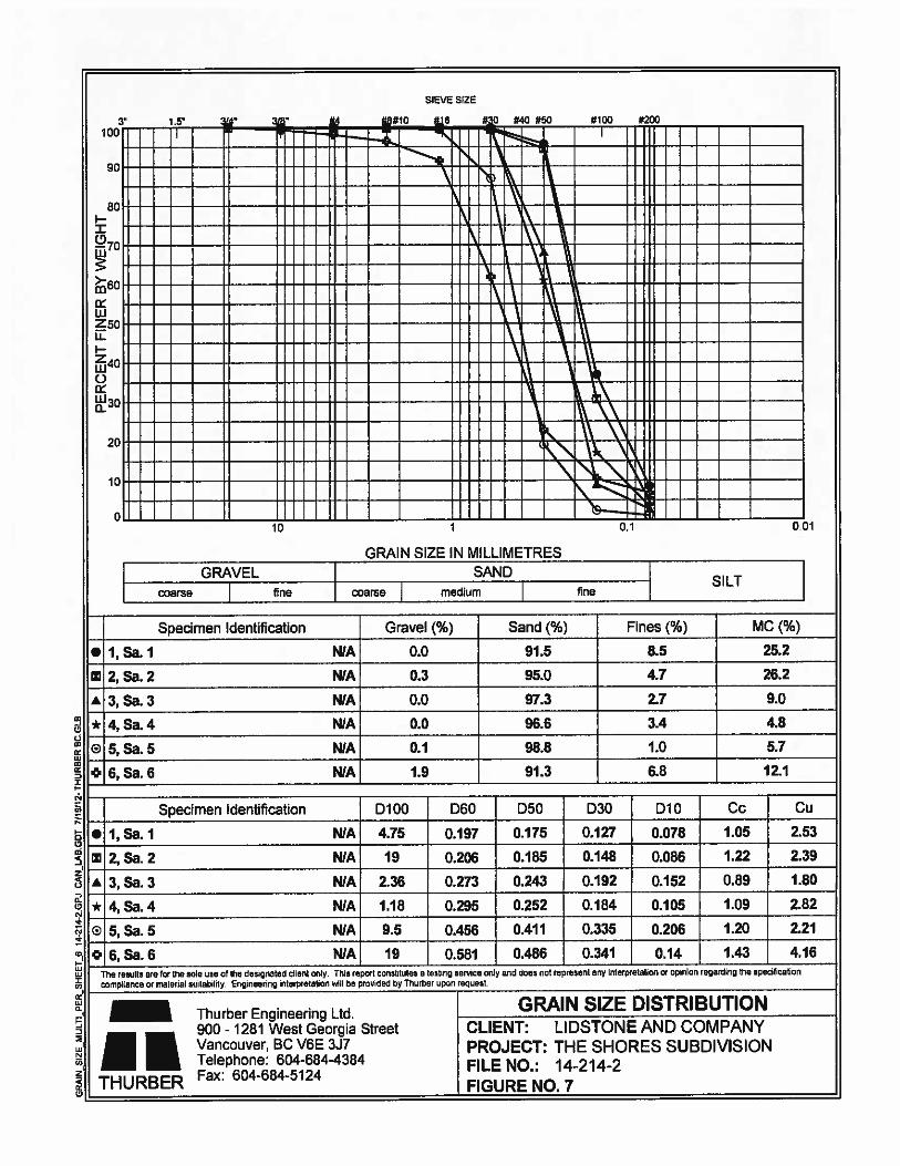
SlEV SEZE
a,
C0a!
wa,
DI
Cya,
I‘a0
0-(3
(0I
huh — E——i “t’ I.—H__\—__--—— --.-
-----_
----—_ -- Th-_
HEr
GRAIN SIZE IN MILLIMETRES
GRAVEL SAND —1 SILTcoarse fine coarse medium fine
Specimen Identification Gravel (%) Sand (%) Fines (%) MC (%)
• 1, Sa. I N!A 0.0 91.5 8.5 25.2
I 2, Sa. 2 N!A 0.3 95.0 4.7 26.2
A3,Sa.3 NIA 0.0 97.3 2.7 9.0
*-4,Sa.4 N/A 0.0 96.6 3.4 I 4.8
N/Aj 0.1 98.8 1.0 5.7
0] 6, Sa. 6 N/A 1.9 91.3 6.8 12.1
Specimen Identification D100 D60 D50 D30 D1O Cc Cu
• 1, Sa. I N/A 4.75 0.197 0.175 0.127 0.078 1.05 2.53
I 2,Sa. 2 N/A 19 0.206 0.185 0.148_- 0.086 1.22 2.39
A 3, Sa. 3 N!A 2.36 0.273 0.243 — 0.192 - 0.152 0.89 1.80
* 4, Sa. 4 N/A 1.18 0.295 0.252 0.184 0.105 1.09 2.82
0 5, Sa. 5 N/A 9.5 0.456 0.411 0.335 0.206 1.20 2.21— — —- —-
0.581 0.486 0.341 0.14 1.43 4.16
The rastlia a’e cr The aole JUC C U-a do-clod cit on T’,s reI: :tns jies a oa:’ 000-Ce Cr. and 3ao r;: rol000lt 07V rocelauon crir 01 read1 ‘r peztt ta’ 01
to .anze:rra or U- st.(ab ty Srgweerrg rararea’lcn W -l be p’:j de Ca Tr.rtar ..0o1 reo..es
_____
GRAIN SIZE DISTRIBUTIONThurber Engineering Ltd
____________________________ ___________________
900- 1281 West Georgia Street CLIENT: LIDSTONE AND COMPANY
I I Vancouver! BC V6E 3J7 PROJECT: THE SHORES SUBDIVISION
____
Telephone: 604-684-4364
THURBER Fax: 604-684-5124 FILE NO.: 14-214-2
I FIGURE NO. 7
3! #l0 aie #0 #40 #50 #100 #200100
90
soII07Q
eo
w250UI2UiC)
30
20
10
00 01
0 6, Sa. 6 N/A 19
Oil
Oil
‘a
0

II
I1tViI
irI!ib
I

——a a a
I tHH14probe“C, ic1%a. h”
Ground Penetrating Radar Survey
for
Thurber Engineering Ltd.Concordia Homes, Sechelt, BC
Terraprobe Geoscience Corp.
4650A Dawson St.Burnaby, BC V5C 4C3
TeL (604) 291-9391Fax: (604) 648-8118
www.terraprobe.com TGC446 — 20120605N

— — a — a
-
I tHHI4probemr I .a&, In fn,d,v rnnsuwç
tcrr.,-nhc 9005C’CflCC corp. tel: 604 2’fl 9391
46SOAdawson St. ‘ax: 604 648 8118burnaby, bc. 1,-mar 9prü:torraprnbc.com
canada, VSC 4C3 web: www.terrapraoe.com
l’rojeci II: IGU 446 - 201 20605NJune 15. 2012.
David J. Iira, M.Sc.A., l’.kng.Principal I C eotech n ical I ngi leer
‘Thurber Engineering ltd.Suite 900, 1281 West Georgia SireetVancouver, B.C. V61i 3J7T. 604 6844384 ext. 118 . 604 684 5124
Attention: Mr. David J. Tara
Re: GPR Survey at Concordia Homes, Gale Ave North, Sechelt, BC
BACKC;RouNL)
Ferraprobe Geoscience Corp. (‘lerraprohe) was commissioned by Ihurber Engineering lid. (‘Ihurber) toundertake a Ground Penetrating Radar (GPR) survey at the (‘oncordia Homes, Phase I, in Gale Ave North,Sechelt, BC.
The objective of the survey was to determine the presence of any possible void or other anomaly beneath thesurface of the road. An anomaly is an urea in the suhsurlhce where the electrical properties are dil’Ibrent thanits surroundings.
The field data collection was conducted on June 5 and June 6, 2012. This report summarizes the technologyoverview. (he survey methodology and the results.
GPR TECHNIQUE
Ground penetrating radar is the general term applied to techniques that employ radio waves to profilestructures and features in the subsurfiwe. Although typically used for ground (soils) applications, (IPR can
he used to identify Features beneath other surfaces. GPR method is based on emission, reflection anddetection of electromagnetic waves. A short pulse of high frequency (10—2600 MHz) electromagnetic energyis produced and transmitted into the ground or other iiedium (i.e. eonerele). The pulse spreads into the
subsurilice materials and is affected by the properties of the surrounding material. Some of the energy is
reflected at the interllice between nialerials of’ dilIbrent dielectric constants. A receiver records 11w rellectedenergy at the surhice. Processed radar data are plotted as surveyed horizontal distance (metres) versus two—
way travel time iii nanoseconds (21) mode). When C PR data are collected in a grid, 31) data processing andinterpretation can be applied.
Terraprobe Geoscience Corp. 4650A Dawson St , Burnaby, B.C.. Canada, V5C 4C3Tel (604) 291 9391. Fax: (604) 648 8118, Vb www terraprobe corn Ernair gpr@terraprobe corn

7
(3 PR Cal) locate both metallic and non—metallic targets. Penetration depth and detectability of targetsdepend on antenna freclLlency, target orientation and the electrical properties of the host material.
ClR FIELI) StJRVEY
A dual frequency (700MHz and 250MHz) (1 P1< systetii by I DX was used for the survey. I )ue to the enormityolthe survey area, the area was divided into 3 different segment. ‘Iheir approximate size of cue!) segment isshown in Table I.Longitudinal lines were collected along the actual road with 0.5 meters apart from each other. ‘l’ransverselines were collected every 5 meters perpendicular to the longitudinal lines. Please note, that Segment #10,#12 and #13 have different line spacing due to the site conditions.
Segment # X max (m) Y max (in)1 46 5.52 55 5.53 25 5.54 110 5.55 100 5.56 100 87 55 88 130 89 120 810 175 811 110 812 20 1713 20 10
Table I Approximate sizes of the surveyed segments. Refer to Figii rc I br location.
I)ATA I’IWCESSIrNC ANI) INTERPRETATION
.nI.nn. mu uu.m.nI Ii
—
B
(ii ‘FR principle and re tiection pro tiling. A: paths of the three nuiii electromagnetic waves. Ii cori’espondiiig single radar
signal. C: resulting radar plot.
C
Terraprobe Geoscience Corp.. 4650A Dawsan St., Burnaby, BC., Canada, V5C 4C3Tel: (604) 291 9391. Fax. (604) 648 8118. Web w.terraprobe.com. EmaiL [email protected]

3
Data processing was done by the lerraprobe’s propnetary RadArt processing and analysis software package.liie Following processing sleps were carried our
• Thrnporal and 2D spatial filters
• Gain recovery• Amplitude analysis• Time—Depth conversion
The interpretation was done manually by ident i l’ing the areas showing relatively high amplitude response.Please note that the anomalies can he caused by numerous reasons. including hut not limited to: differentelectrical properties in the host materiaL (i.e. different water content. di Flërent minerals), void space.embedded human-made objects (tank, concrete, metal or plastic pipes etc).
GPR REStJLTS
The dual frequency GPR system provided sufficient data quality, although the signal penetration depth waslimited to approximately 3Mm probably due to the soil conditions. Figure I shows the approximate locationof the survey area as well as the approximate location oF the G PR cross sections that are shown in Figure 2to 14.The results can he summnrized as follows:
• There appear to be sonic significant anomalies of di Ft&ent sizes. ‘[he localion of each anomaly ismarked with a red oval on the GPR cross sections in Figure 2 to Figure 14. The depth scale of thecross section is exaggerated. The depth of the anomalies is generally within (lie first 3 meters belowthe surface.
• In Segment #1 (Figure 2)the marked anomaly is located in the area where an existing sinkhole wasdiscovered and filled hack prior to the (iPR survey.
• Segment #9 (Figure II) was surveyed in 11w round about around the island. 11w start location ismarked with pink arrow with the direction ol’ the line both on the layout (Figure 1) and in Figure IIabove the GPR cross section.
• The exact location of each anomaly can be marked off on site if adequate drawings are madeavailable.
CONCLUSIONS AM) RECOMMENI)ATIONS
[he true nature of the marked anomalies cannot he verified based on the (JPR data only. It is recommendedto mark all the anomalies on site and correlate with the existing geological features and with the existingman made structures, i.e. manholes and pipes. Also it is recommended to excavate or drill the anomalies inorder to verify their nattire,If required, a lower frequency (3 PR survey can be carried out in the area to extend the depth and the area of
[lie investigation.
Terraprobe Geoscience Corp 4650A Dawson St., Bumaby, B C. Canada. V5C 4C3Tel (604) 291 9391, Fax. (604)6488118. Web w.terraprobe.corn, EmaU: [email protected]

4
LIMITATIONS
The depth to subsurthee i’eat ures derived from ground penetrating radar surveys arc generally accepted asaccurate to within ten to twenty percent of the true depths to the boundaries. Since the depth scale wascalculated using average velocities it could oniy he used as a guideline and not as accurate measurement.flie results are interpretive iii nature and are considered to be a reasonable accurate presentation of existing
conditions within (lie I un itations of the radar proW ing method.
11w in lbrmation in this report is based upon radar measurements, the in lonuation provided to us and our
interpretation ol’ the data.
Ihank you Ibr choosing Terraprobe. ii you have any gtiestions regarding this report please feel free to
contact us.
Best regards,
Peter lakacsProject Geophysicist, DipI. Geo.i’eiTaprobe Geoscience Corp.
Terraprobe Geoscience Corp., 4650A Dawson S:, Bunaby. B.C., Canada, V5C 4C3Tel: (604) 291 9391, Fax. (604) 648 8118, Web. wvmterraprobe.com, Email: gpr©terraprobe.com

a,-c0
a,NU,
V —
0ct
ct
‘aj
a,-c0U,€0a,CD
C,C,C0,Ca,
C,—Dd8U,
a, C,00 = =ZZF—I
I
C)C
C,=UC,
C),
t0zC,
4C,a,0nC.,10•0
C,
C),IC,
‘OC,
0)C
C,
C,CC,0.VC2
2C,
—
t
C
P
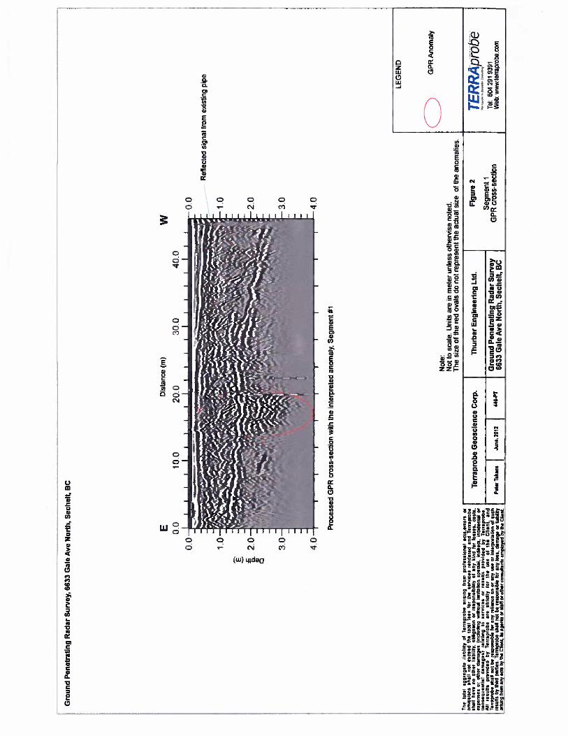
Vis
eto
tal
aggre
gat
eia
hub
ofTe
era
pro
be
aits
inp
tres
spr
ore
soio
naf
scot
.eeo
nrs
oro
nio
n’
son
shal
lso
bcore
rd
the
tota
lfe
esno
rth
ese
rvic
esre
nd
ered
art d
Ter
rapre
be-
shal
thav
eno
ether
liab
rirl
y.obli
gat
ion
orre
sponsi
bil
ity
toan
yki
ndfo
rIo
nse
t,co
sts.
expen
ses
oroth
erd
amag
es(i
nclo
ding
wit
hout
imit
atio
nsp
ecia
l,in
dite
ci.
inci
den
tal
or-
con
ceqij
enti
nr
dar
ota
nes
tre
lati
ng
tose
rvic
es
orre
soil
spro
vid
edby
Ter
iap
rob
eI
eesi
stcs
pro
vid
edby
Ter
rapro
be
are
stti
city
toe
lie
use
onth
eC
hest
,en
dT
enra
prob
eth
at
not
bere
spo
nsi
ble
ear
any
reli
ance
enor
any
use
orin
teep
rela
tion
orso
thie
solt
sby
thir
dpa
ruie
s.T
eria
pro
be
shal
tno
tbe
rrn
po
nsi
ble
toe
any
lois
,dam
age
orba
bild
yai
iepy9rr
nm
aojr
acio
byth
eC
lient
.d
agen
tsor
otaf
for
othe
rco
nsoh
anos
empl
oyed
bf
iise
cben
l
Gro
und
Pen
etra
tin
gR
adar
Sur
vey,
6633
Gal
eA
veN
orth
,S
ech
elt,
BC
E 00
S ‘C 0,
0a a
10.0
Dis
tanc
e(m
)
20.0
300
w40
.0
0-0
1.0
Ref
lect
edsi
gnal
from
edst
ing
pipe
20
Pro
cess
edG
PR
cros
s-se
ctio
nw
ithth
ein
terp
rete
dan
omal
y.S
egm
ent
#1
3.0
4.0
Not
e:N
otto
scal
e.U
nits
are
inm
eter
unle
ssot
herv
ise
note
d.T
hesi
zeof
the
red
oval
sdo
not
repre
sent
the
actu
alsi
zeof
the
anom
alie
s.
Th
urb
erE
ng
inee
rin
gL
td.
Gro
und
Pen
etra
tin
gR
adar
Sur
vey
6633
Gal
eA
veN
orth
,S
ech
elt,
BC
GP
RA
nom
aly
Fig
ure
2
Seg
men
L1
GP
Rcr
oss-
sect
ion
TER
RA
prob
eTe
l:60
429
193
91W
ebw
Mvl
erra
prob
e.co
m

Gro
und
Pen
etra
ting
Rad
arS
urve
y,G
G33
Gal
eA
veN
orth
,S
ech
elt,
BC
The
tota
lag
ote
gat
eli
abil
ity
ofT
erra
pro
be
ari
sina
tram
pro
fess
ion
alac
ts.e
rrart
or00
1115
31ons
shal
lnu
toac
eoa
the
tota
lfe
et
far
the
smv
ices
reoden
od
anT
erra
pra
be
shal
lhav
eno
nth
erli
abil
ity,
obli
gat
ion
orto
op
onsb
ilil
yof
any
kind
mr
loss
es.
0051
1to
po
n0
05
orsi
b,,
dam
ate
s{i
nci
ud
isg
wit
hout
ljn
iilt
tio
nlp
ecia
I.in
dir
ect,
inci
den
tal
oral
dam
ag
es)
tela
tin
pII
5C
lVse
ton
insu
lts
pto
aid
ed
byT
er,
aprs
be.
All
resu
lts
pro
vid
edby
l’er
raprn
bn
are
stri
ctly
far
‘he
use
of(h
oC
lien
t,an
dT
et,a
pnob
esh
all
101
bere
spo
nsi
ble
for
any
reli
ance
onor
any
use
orin
ieop
nefa
tion
01su
chre
suil
sby
thir
dp
arti
es.
Teo
raprt
be
shu
tri
otbe
resp
onsi
ble
‘Or
any
lost
,dam
age
orlia
bilit
yan
suag
irnn
aan
yac
tsby
the
Chen
tits
agen
tsor
staf
for
othe
rce
rosl
ants
etsp
dsye
dby
the
Cli
ent
E 00
0.0
10.0
Dis
tanc
e(m
)
20.0
10
300
400
w
E ‘C a C,
C2.
0
500
30
4.0
Pro
cess
edG
PR
cros
s-se
ctio
nw
ithth
ein
terp
rete
dan
omal
y,S
egm
ent
#2
Gro
und
Pen
etra
tin
gR
adar
Su
rvey
6633
Gal
eA
veN
orth
,S
echel
t,B
C
GP
RA
nom
aly

E -t a C) a
Gro
und
Pen
etra
ting
Rad
arS
urve
y,66
33G
ale
Ave
Nor
th,
Sec
hel
t,B
C
ED
ista
nce(
m)
0.0
5.0
10.0
15.0
20.0
0.0
1.0
1.0
ED
ista
nce
(m)
w0.
05.
010
.0
0.0
S a C) C
2.0
3.0
w
15.0
20.0
25.0
Iiii
Iii
Iii
IR
efle
cted
sign
alfr
omex
isti
ngpi
pe
H1.0
-20
—3.
0
—4.
04.
0I
It
It
II
III
II
III
II
II
It
III
III
II
III
Pro
cess
edG
PR
cros
s-se
ctio
nw
ithth
ein
terp
rete
dan
omal
yS
egm
ent
#3P
roce
ssed
GP
Rcr
oss-
sect
ion
with
the
inte
rpre
ted
anom
aly
Seg
men
t#3
Th
eto
tat
aggre
gote
liab
ilit
yof
l’e,
rapno
br
aris
ing
r,o
,npa
nte
ssi a
nal
acts
.ent
orn
oron
sisn
iens
shal
ln
ot
exce
edth
est
atle
tsfo
rth
ese
nnic
esre
sdete
dan
dT
erra
pro
be
shal
thav
eno
oth
erli
abil
ity,
obti
gah
na
tore
sponsi
bil
ity
ofan
ybi
ndbr
loss
es,
cost
s.ex
pen
ses
oto
ther
da‘n
agrs
incl
udin
gw
itho
utlm
rttt
iet
spec
iaI.
ind
irec
t,in
ciden
tal
oxco
nse
qu
en
tial
dan
sag
esl
rela
ting
tose
rvic
es
orte
sult
spro
vid
edby
Ter
tap
rob
eA
llre
ssll
sp
ovid
edby
Te
ma
pro
be
ace
stoi
c‘I
fto
tth
eu
seor
the
cli
en
t,an
dT
erra
pro
be
shal
lno
nbe
sesp
on
sib
leto
tan
yte
iian
ceon
oran
yn
sfor
inte
mpi
etat
ion
ofso
cti
eess
itts
bytti
iad
pad
ies.
Tei
oapi
obe
shal
lno
tbe
resp
oas
ibie
tot
any
loss
,d
amag
eot
liab
ildy
ahsi
eig
russ
oaf
fyads
byus
eti
est,
itsag
ents
cmst
aff
oio
lbet
cons
alta
nts
erns
slny
edtyy
the
Che
et
LE
GE
ND
Th
urb
erE
ng
inee
rin
gL
td.
CG
PR
Mom
aly
Gro
und
Pen
etra
tin
gR
adar
Surv
ey66
33G
ale
Ave
Nor
th,
Sec
hel
t,B
C
TE
prn
be
Tel:
604
291
9391
Web
:v,
wsv
tenr
apro
be.c
om

S C a a, C
S -c a a) C
The
tota
lap
gre
gal
eli
abil
ity
ofTo
ira
pro
be
aris
ing
from
pro
less
ion
aa
cis.
ero
ors
orom
issi
ons
shal
lno
tex
cee
dth
eto
tal
tees
for
the
sery
icesr
eo
dn
oed
an
dTe
trap
tebe
shal
lhav
eno
eth
erlI
abil
ity,
obli
gat
ion
ari
es
po
esib
ilit
yof
any
hni
tfo
rlo
sses,
cost
s.expen
ses
onet
her
dam
ages
(Inc
ludi
ngw
itho
utli
mit
atio
nsp
ecia
l,in
ditea
ioct
den
tal
orco
ose
qu
rot”
al
dam
ages)
cr10
1109
tose
rvic
es
onre
sult
soro
elde
dby
Tet
rap
rob
eA
lIre
sult
sp
rovid
eit
byT
erra
pro
bear
est
rict
lyor
the
use
oflb
oC
lien
t,an
dT
erra
prob
esh
agno
tbe
resp
on
sib
lelo
tan
yre
lian
ceon
oran
yu
sea
rin
teep
eeta
tio
not
sou
rG
roun
dP
enet
rati
ng
Rad
arS
urve
yre
sult
sby
thir
dpa
role
sT
erra
pro
be
shal
not
beie
spcn
slble
eor
any
loss
,dam
age
orha
bilit
yI
p.a
.rT
aboo
sI
Jun
..20
12I
440-
PT
6633
Gal
eA
veN
orth
,S
eche
lt,
BC
aim
aip
from
any
acts
byth
eC
lien
t,as
aen
os
orst
affe
rot
her
mto
sstl
aots
empl
oyed
byth
eC
fieoO
TER
RA
prob
eTe
L60
429
193
91W
ebsw
w.te
rrap
robe
.com
Dis
tanc
e(m
)
Gro
und
Pen
etra
ting
Rad
arS
urve
y,66
33G
ale
Ave
Nor
th,
Sec
helt
,B
C
E
0. 2. 3.0
500
w10
0.0
4.0
E 00Pro
cess
edG
PR
cros
s-se
ctio
nw
ithth
ein
ierp
rete
dan
omal
y.S
egm
ent
#4
Dis
tanc
e(m
)
500
w1000
Pro
cess
edG
PR
cro
ss-s
ecti
on
with
the
inte
rpre
ted
II
II
II
—I
II
anom
alyS
egm
ent
#4
GP
RA
nom
aly

C a 0) C
Dis
tanc
e(m
)w
50
0‘5
0
Gro
und
Pen
etra
ting
Rad
arS
urve
y,66
33G
ale
Ave
Nor
th,
Sec
hel
t,B
C
E 00
25
0
ooL
-
oHC
-
&2
0a
-
on-
30—
30—
Pro
cess
edG
PR
cros
s-se
ctio
nw
ithth
ein
terp
rete
dan
omal
y,S
egm
ent
#5
ED
ista
nce
(m)
W
00:1
l0
C £20
a en C10
4(1—
EPro
cess
edG
PR
cros
s-se
ctio
nw
ithth
ein
terp
rete
dan
omal
y.S
egm
ent
#5
Dis
tanc
e(m
)W
00 l0
2
0
30
SillIlI
-0
LE
GE
ND
Pro
cess
edG
PR
cros
s-se
ctio
nw
ithth
ein
terp
rete
dan
omal
y,S
egm
ent
#5G
PR
Ano
mal
y
The
tota
lag
gre
gal
eli
abil
ity
ofT
erra
pro
be
aris
ing
frog
spr
ote
ssian
alac
tser
rors
°I
Ia
mm5lO
tSsh
all
no
tex
ceed
the
tota
lle
es
foe
the
sera
ices
ren
der
edan
dre
rrap
rob
eI
II
——
—sh
all
havens
oth
erli
asil
ily
,o
bli
gah
nn
orre
tp
onni
bilim
yof
any
kInd
for
loss
es,
cools
.I
Ter
rap
rob
eG
eosc
ience
Cor
p.I
Th
urb
erE
ng
inee
rin
gL
td.
IF
igur
e6
1tic
tcA
/rcL
beeopets
es
oro
ther
dam
ages
Iitcl
udi1
19w
ilho
aolim
nrta
l,an
spec
laI.
indl
reca
.in
ciden
tal
orI
con
seq
uen
tial
darn
sag
est
rela
tIng
tose
rvic
es
or
resl
ills
pro
vid
edby
Ter
ropro
be
II
‘
Ter
map
lobe
shat
not
bere
spo
nsi
ble
for
any
reli
ance
onor
any
Use
ori
ole
Ipre
fati
onOf
Ouc
hI
.I
Gro
und
Pen
etra
tin
gR
adar
Su
rvey
IG
PR
cros
s—se
ctio
nsW
ebw
ww
lerr
apro
be
can
All
resu
lts
pro
eided
byT
err
ap
rob
ear
est
rict
lyfo
rth
eu
seo
fsh
eO
tiro
t.an
dI
Seg
men
tST
el604
291
9391
resu
lts
byth
ird
pad
ies-
Teo
ayo
ob
esh
all
not
here
syo
nsi
ble
for
any
toss
.dam
age
oria
sila
yP
,trr
Tfl
ans
IJu
n..
2012
446-F
r66
33G
ale
Ave
Nor
th,
Sec
hel
t,B
Cy
yy
fng
rroyy
lcl
ient
itsag
ents
orst
aff
orot
her
con
son
ants
ensp
loye
dby
the
Cse
noI
I
______________________________

F -c a a, a
-T
ire
torn
agg
reg
ate
liab
ilit
yof
Tear
pro
be
aris
ing
From
pit
test
ieo
nI
acts
,err
ors
orai
rssh
all
no
tencre
dth
etr
Ial
fees
for
the
serv
ices
ren
der
edan
dT
erra
pro
be
shal
lhavens
ofh
erli
abil
ity
obli
gat
ion
ores
pari
sib
ility
ofal
lybir
dfo
rlo
sses
cost
s.erp
ense
sor
othe
dam
ages
fiac
ludir
pw
ith
oal
lim
itat
ion
apeo
aI,
Indir
ect
oci
den
fal
orco
noeo
uen
hia
fd
am
ag
esf
isla
tin
5to
serv
ices
orre
sult
spro
vid
edby
Ter
iap
rob
e.A
llre
sult
spro
vid
edby
Ter
rapro
be
ale
stri
clty
for
the
use
ofth
eC
lien
t,an
dT
eria
pto
be
thtt
not
bete
spo
nsi
bfe
for
aty
reli
arce
or
orso
yu
seor
inte
rpre
tati
on
ofsu
chre
sult
sby
hind
pat
ties
-T
eira
pcob
esh
aft
sot
bere
sponsi
ble
for
any
loss
,dam
age
orha
bild
yar
bar
gfr
aman
yac
tsb
yth
eG
lenn
.dsa
jypts
orno
att
orot
her
conso
oan
tstm
plo
yef
by
es
Cli
ent
Gro
und
Pen
etra
ting
Rad
arS
urve
y,66
33G
ale
Ave
Nor
th,
Sec
helt
,B
C
250
Dis
tanc
e(m
)E 0
0
00
10
F £2
0a a) a
30
40
500
w75
0
E 00
00
Pro
cess
edG
PR
cros
s-se
ctio
nw
ithth
ein
terp
rete
dan
omal
y,S
egm
ent
#6
Dis
tanc
e(m
)
250
500
ibM
II
w00
Pro
cess
edG
PR
cros
s-se
ctio
nw
ithth
ein
terp
rete
dan
omal
y.S
egm
ent
#6 Thu
rber
Eng
inee
ring
Ltd
.
Gro
und
Pen
etra
tin
gR
adar
Sur
vey
6633
Gal
eA
veN
orth
,S
eche
lt,
BC
GP
RA
nom
aly
T1pro
be
Tel.
604
291
9391
Web
:vA
’vw
tere
aprc
be.c
om

Gro
und
Pen
etra
ting
Rad
arS
urve
y,66
33G
ale
Ave
Nor
th,
Sec
hel
t,B
C
B -c a 0) a 2 -C a 0) a
The
mIn
iag
gmeg
ane
liab
ilit
yci
Ter
rapr
obe
aris
Ing
loom
pro
Ces
sion,
Iac
ts,e
rrors
ornot
shal
lno
tto
tted
heto
tal
fees
for
the
serv
ices
ren
der
edan
dl’
erra
pro
be
shal
lhavens
oth
erli
abil
ity,
obli
gat
ion
orno
np
nnst
bili
tyof
any
kind
for
Itss
es.
cents
.ex
pen
ses
Or
oth
e,dam
ages
(inc
tiad
lop
wil
hont
lim
llat
ion
spec
taI,
ind
irec
t,in
cid
enta
lno
Id
ama
get)
roIn
ning
tose
rvic
es
or
nosu
lts
pro
vid
edby
Ter
rap
roh
eA
llre
sult
spro
vid
edby
Ter
rap
rob
oar
est
ric
fly
for
the
use
ofth
eC
tien
t.an
dT
etoa
ptob
esh
all
nor
bere
spo
nsi
ble
for
any
reli
ance
onor
any
use
orin
toop
teta
tion
cinoel
resu
los
byth
irdpas.
Tenra
poo
shat
not
bere
spo
nsi
ble
foe
any
Ions
.dat
nao
eor
lias
ilny
jar
issn
gjyy
yys
any
acts
byti
eC
ken
tft
aoer
ds
orst
aff
orot
her
cora
saha
rnos
eniX
yn
dby
the
Che
st.
0.0
10
02
00
300
40
05
00
ED
ista
nce
(m)
0 20 3.0’
wE
Dis
tanc
e(m
)w
ED
Ista
nce
(m)
00 10
20 30 4°
w00 10
2.0
3.0
40
Pro
cess
edG
PR
cros
s-se
ctio
nw
ithth
ein
terp
rete
dan
omal
y.S
egm
ent
#7
-C 0) a
Pro
cess
edG
PR
cros
s-se
ctio
nw
ithth
ein
terp
rete
dan
omal
y,S
egm
ent
#7
LE
GE
ND GP
RM
om
aiy
Ter
rap
rob
eG
eosc
ience
Cor
p.T
hurb
erE
ng
inee
rin
gL
td.
IF
igur
e8
TER
RA
pro b
eS
egm
ent
760
429
193
91G
round
Pen
etra
tin
gR
adar
Suey
GP
Rcr
oss-
sect
ions
Web
terrap
ro
corn
PM
.,S
ahar
aJu
n..
2t1
244G
’fl
6633
Gal
eA
veN
orth
,S
ech
elt,
BC

-T
hefo
lai
ag
9te
9a
toli
abil
ity
ofre
rca
pro
be
atis
inti
eas
pro
fess
ion
alacfs
,enart
oro
reis
sion
sot
tail
ntf
once
odth
eto
tal
fees
jet
the
ber
vic
esre
otd
eted
and
lerr
apro
be
shal
lhav
eno
ether
liab
ilit
y.obli
gat
ion
or‘C
sp
on
sib
ilit
yft
any
kind
It,
toss
es,
cast
s.en
oth
erdam
ages
inct
adin
gin
tbo
atli
mit
atio
nsp
ecia
l.,n
dir
ncl
,it
ciden
tnl
Oi
ets
equenfi
atdam
ng
es)
tela
tin
pit
seto
lces
orre
mus
pn
od
ded
byTe
resp
rob
eA
ltee
sutt
sprt
vudod
byre
na
Pt0
bear
est
rtct
tylo
tth
euse
ot
ohe
Cli
ent,
and
Ti
toap
eobe
shet
tot
bere
sponsi
ble
for
any
reli
ance
onor
any
abe
orin
tetp
tela
tiat
ofso
cli
resu
lts
byth
ird
pa’
ties
Tee
rapr
obe
sho
tea
tbe
resp
on
sib
leO
s,an
ylo
ss,
dam
ase
rrli
abil
ayanogjy
yany
aos
by(S
ueC
hen
tits
ape
net
orst
aff
orot
her
tonsu
tants
Gro
und
Pen
etra
ting
Rad
arS
urve
y.66
33G
ale
Ave
Nor
th,
Sec
helt
,B
C
E 00
Dis
tanc
e(m
)
500
100
0w
00 1-0
20
30
40
00 10 2.0
10
40
S ‘C a 00 0 S ‘C a to 0
E 00P
roce
ssed
GP
Rcr
oss-
sect
ion
with
the
inte
rpre
ted
anom
aly,
Seg
men
t#8
Dis
tanc
e(m
)
50.0
1000
w
00
Pro
cess
edG
PR
cros
s-se
ctio
nw
ithth
ein
terp
rete
dan
omal
y,S
egm
ent
#8
1.0
—20 40
Gro
und
Pen
etra
tin
gR
adar
Sur
vey
IP
eer
Tah
oe,
IJu
nn
.20
12I
‘P
TI
6633
Gal
eA
veN
orth
,S
eche
lt,
BC
GP
RA
nom
aly
Tp
rn
be
TeJ
604
291
9391
Web
v.’w
wte
rrap
robe
.com

Gro
und
Pen
etra
ting
Rad
arS
urve
y,66
33G
ale
Ave
Nor
th,
Sec
helt
,B
C
00”
E-
‘C-
‘a20-f
a,-‘
C
Th
eto
tal
ag
gre
gate
liab
ilit
yol
Tirr
apro
be
afl
slt
fron
tp’s
less
en
aI
aat
sern
ois
orom
issi
ons
shal
ln
ot
esc
ee
itth
eto
tal
fees
‘0,
Ihe
sen
iice
snen
der
edan
dT
eria
pto
be
shal
lti
av
en
0oth
erli
abil
ity,
obli
gat
ion
orm
sp
on
sib
ilil
yof
any
bind
‘or
oso
esco
sts.
esp
ense
sor
olh
erd
amag
esli
nd
ang
wit
hout
lim
itat
ion
spec
ial.
indin
ect
inci
den
tal
orco
eise
qn
est
leI
dam
ages)
eela
sln
5so
serv
ices
orre
soll
sp
rov
ided
byT
eera
pro
be.
All
resu
lts
pro
vid
edto
yT
erra
pta
bear
esi
llca
lfan
,ti
euse
ofti
ecI
teof
.an
dT
eeoa
peob
ech
at
riot
bere
spo
nsi
ble
en,
any
reli
ance
enor
any
use
a’in
teep
rela
tion
ofsu
rf,
resu
lts
byoi
,rd
par
tIes
.T
eera
prst
aesh
unno
tbe
resp
onsi
ble
for
any
Into
,dam
age
orli
abil
iae
from
slaya
by
the
Cie
rit
esag
ern
lsor
staf
fer
othe
rco
nso
nan
tsem
ploy
edby
the
Ce
Thu
rber
Eng
inee
ring
Ltd
.
Gro
und
Pen
etra
tin
gR
adar
Sur
vey
6633
Gal
eA
veN
orth
,S
eche
lt,
BC
TER
RA
prob
eTe
l:50
429
193
91W
ebv.
wiv
terr
apro
beco
rn
E 00
200
Dis
tanc
e(m
)
400
600
800
2 ‘C 0,
C) C
100
0
w12
00
Pro
cess
edG
PRcr
oss-
sect
ion
with
the
inte
rpre
ted
anom
aly.
Seg
men
t#8
E 00
Dis
tanc
e(m
)500
100
0w
40
30 0
Pro
cess
edG
PR
cros
s-se
clio
nw
ithth
ein
terp
rete
dan
omal
y,S
egm
ent
#8
‘—1
—2M
:°
“40
GPR
Ano
mal
y

E a a) 0
The
tota
lag
gre
gat
eli
abil
ity
otIc
trap
rob
earn
itg
fron
tp
tote
ssto
tta
Iac
ts.t
rroe
sor
otni
sti
ats
spat
no
teo
cee
the
t000
tte
es
or
tie
serv
ices
eender
eda
tdT
erta
peob
esh
all
hate
tooth
etti
tbit
tty,
abli
gat
iot
orre
sp
oss
ibil
ity
ofan
yhi
ndor
toss
esco
sts.
oro
ther
dam
ages
tnct
adit
gw
itho
utim
itat
Ion
spec
ial
itdtr
ect,
nctd
ett
alor
icn
nse
gh
en
hat
dat
na
gesi
rela
tttg
tose
rvic
es
orre
sttl
tsprt
vtd
ed
byT
erta
pto
be
AlI
rest
tts
pto
t’ded
byT
erra
peo
he
ate
strt
ctly
1°c
the
on
ofth
eC
tten
l.atd
Ter
rop
rtb
esh
aano
tbe
reo
po
tsib
leto
taty
reti
atce
at
ttaty
tot
orin
terp
reta
tIo
nof
sud
tte
sato
sby
thir
dptn
’es
Tet
tapto
be
shal
tno
tbe
resp
ots
ible
lot
aty
loss
.d
anta
ge
orba
biT
ityar
min
gtr
amo
tyaos
by
the
Cli
eto.
itsag
etts
orso
atfo
rot
her
ceno
riro
asts
omrl
oyed
byth
eC
lien
t
—
Gro
und
Pen
etra
ting
Rad
arS
urve
y,66
33G
ale
Ave
Nor
th,
Sec
hel
t,B
C
0.0
1.0
Dis
tanc
e(m
)
2.0
3.0
4.P
roce
ssed
GP
Rcr
oss-
sect
ion
with
the
inte
rpre
ted
anom
aly.
Seg
men
t#9
Ter
rapro
be
Geo
scie
nce
Cor
p.
Not
e:S
egm
ent#
9is
aci
rcum
fere
stia
lse
gm
ent
The
star
tan
den
dlo
cati
onof
the
GP
Rcr
oss
sect
ion
isap
prox
imat
ely
the
sam
elo
catio
n.In
Fig
ure
1.a
pink
arro
wre
pre
sents
the
dire
ctio
nof
the
cros
sse
ctio
n.
Pete
rT
aboo
sJu
n.,
2Q12
Th
urb
erE
ng
inee
rin
gL
td.
LE
GE
ND GP
RM
om
aly
0
Gro
und
Pen
etra
tin
gR
adar
Su
rvey
I66
33G
ale
Ave
Nor
th,
Sec
hel
t,B
C
Fig
ure
II
Seg
men
t9
GP
Rcr
oss-
sect
ion
TEpr
o be
TeL
604
291
9391
Web
yAw
ltar
rapr
obe.
ccrn

E -c a 0J C
10-
E20
—-C
-
a 0-
C30-
40-
Gro
und
Pen
etra
ting
Rad
arS
urve
y,66
33G
ale
Ave
Nor
th,
Sec
hel
t,B
C
000
0-
Dis
tanc
e(m
)50
01000
15i]
Q
Pro
cess
edG
PR
cros
s-se
ctio
nw
ithth
ein
terp
rete
dan
omal
y,S
egm
ent
#10
00
0._
256
50.0
750
1000
Dis
tanc
e(m
)
1._
I-—1
i_
ii_
_i
_l___
i—
II
-i_
i
__
-
___
125.
015
0.0
Pro
cess
edG
PR
cros
s-se
ctio
nw
ilhth
ein
terp
rete
dan
omal
y.S
egm
ent
#10
:00
:1.0
—2.
0
—3.
0
41
Not
e:S
egm
ent
#10
was
cotl
ecte
don
asl
ope
Dis
tanc
esh
own
isli
near
dist
ance
onsu
rfac
eof
the
road
.T
heT
otal
agg
reg
ale
rIab
iliTy
nOT
e,ia
pro
be
aris
ing
from
rinie
sbi a
nti
acts
erro
rsat
ens
shal
lno
rerc
ee
dtie
Tot
alte
enfo
rih
ese
rvic
er
ren
der
edan
dT
ern
apro
be
shel
lhav
eno
oth
erli
abil
ity.
ob
lin
airn
nnr
res
pons
ibil
iny
ofan
yki
ndfo
rIo
nn
es,
cost
s.eo
pen
ses
oro
iher
dam
ages
inci
tuin
pw
iili
oai
f:m
iial
rnn
spec
ial,
ind
irec
t.in
ciden
iat
orcon
seq
uen
tial
dam
ag
esf
‘elf
iin
oTn
sem
i sos
or
resu
lts
pro
vid
edby
Ter
rap
rob
e.M
Ire
soli
spro
vid
edsr
Tn
rrap
rob
ear
est
rict
lyfo
ris
ense
0’th
,cli
ent,
and
Ter
rapro
be
shal
lro
tbe
resp
onsi
ble
foi
any
neti
ance
tnt,
toy
fine
Oin
terp
reta
tio
nor
wea
rre
sort
sby
thir
dpas.
Teir
op
iosh
all
noi
bere
spo
osi
ble
nor
any
loss
,d
amag
eon
tabi
lity
mm
n0m
man
yac
tsby
tileC
iten
its
Orso
aff
0,
rura
lro
mal
nan
isen
ipdo
yed
bylim
ecl
ient
Ter
rap
rob
eG
eosc
ience
Co
rp.
Th
urb
erE
ng
inee
rin
gL
td.
Gro
und
Pen
etra
tin
gR
adar
Su
rvey
446.
r66
33G
ale
Ave
Nor
th,
Sec
hel
t,B
C
GP
RA
nom
aly
TER
RA
pro b
eTe
l60
429
193
91W
ebw
ww
.terr
apro
be.c
om

Dis
tanc
e(m
)
50
10
01
50
III
Iii
ii
iiii
—
- z -
-
:_
-—
.i’
pI
II
II
Iiti
i
Pro
cess
edG
PR
cros
s-se
ctio
nw
ithth
ein
terp
rete
dan
omal
yS
egm
ent
#12
Gro
und
Pen
etra
tin
gR
adar
Sur
vey,
6633
Gal
eA
veN
orth
,S
ech
elt,
BC
E 00
w
E a 0 0
00
00
1.0
20
30
40
10
-
E 00
Dis
tanc
e(m
)
0.0
50
w10-0
—2
.0
1.0
0-0
E -c a 0 0
:30
2.0
10
:40
30
20
4.0
30
Pro
cess
edG
PR
cros
s-se
ctio
nw
ithth
ein
terp
rete
dan
omal
y.4.0 S
egm
ent
#12
he
iota
,ay
gre
gate
iao
ilil
ynf
lT
etn
apncb
eatO
mp
born
pen
tess
’fi
nal
oats
.e‘O
r,no
ence
oa
seto
tal
tees
‘or
the
set-
nic
eo
ren
dered
.so
Ter
rap
rob
e-
sha
0hane
na
oth
er
IaS
ilty
.obli
gati
on
vi
resp
nrr
sd
ity
ofaf
lyki
ngy
e,lo
sses
Cost
..-
enpen
ses
or
oth
eF
dam
ages
incl
udin
gan
t bont
lauvnat
’nn
specia
I.rn
drr
eci
incid
enta
lfi
t
Conse
ouen
fl’a
ld
arn
afle
sire
lati
ng
tose
toic
es
or
result
spro
vid
ed
by
Terr
apin
se.
AlI
resu
lts
pro
vid
ed
byT
erra
pro
be
ate
sl,r
cti
pto
nth
evie
ol
the
cli
eni.
and
-T
einap
isbe
shoe
riot
bere
apo
otb
elo
tan
y,.Ia
n;e
on
nr
any
noon
OF
‘nm
erpee
tabois
sIsu
d,new
tsby
bird
paro
nes
Ter
napr
obe
ssat
not
be‘e
spo
nsb
fie
fnr
any
loss
.dam
age
orL
abit
y-
nrr
stp
lro
nn
ay
yo
ds
byrn
edent
Csyg
ents
flusl
anor
cOre
roosserr
ceygih
ecser4
.
Th
urb
erE
ng
inee
rin
gL
td.
Gro
und
Pen
etra
tin
gR
adar
Surv
ey66
33G
ale
Ave
Nor
th,
Sec
hel
t,B
C
TER
RA
prob
eTe
!604
29
’93
91W
ebw
ww
terr
apro
ccrn

Gro
und
Pen
etra
ting
Rad
arS
urve
y,66
33G
ale
Ave
Nor
th,
Sec
hel
t,B
C
E -C a 0) a
E -c a 0 a
The
tots
Iag
gre
gate
habi
tity
ofT
etra
pto
be
nois
ing
from
pto
fess
lon,
Ia
cit
erro
rsor
om
iati
ons
shal
tn
ot
eoce
ed
the
tota
lre
esro
eth
ese
mic
et
ren
der
edan
dT
eira
pro
be
thou
hav
eno
oth
erli
abil
ity,
obli
gat
ion
orre
sp
oss
ibil
ity
ofan
yki
ndfo
rto
sses
cost
s.eo
per
tnen
oro
ther
dam
ages
(iac
loth
n9
wit
hout
lim
itat
ion
spec
Ial,
ind
ited
,in
cid
enta
lor
con
aeq
oen
tiat
dania
ges)
Fea
finn
tose
rvic
es
orre
sult
sp
rnai
ded
hr
Ter
rap
rob
e.A
lIin
sult
spro
nid
edby
Ter
rap0
0be
are
ann
cti
yfa
rth
euse
of
the
Cli
nt,
and
Terr
apro
be
shal
not
be
resp
onsi
ble
tot
any
reli
aace
on
or
any
line
Or
inte
rpre
tati
on
of
suds
result
,by
thir
dpa
rtie
s.T
err
apro
be
shat
nu
tbe
len
poosi
bie
far
any
lass,
dannage
or
tiabil
it1
alm
aig
hm
any
aco
sby
Chent
it.
ap
eats
or
soaft
oro
hur
su
tan
tsensø
o,y
ed
hyth
eC
heat
Gro
und
Pen
etra
tin
gR
adar
Su
rvey
6633
Gal
eA
veN
orth
,S
echel
t,B
C
TER
RA
prob
eTe
l60
42
993
91V
I/eb
‘Mw
/.te
rrap
rob
o.C
orn
Dis
tanc
e(m
)
0.0
50
10.0
15.0
20.0
0.0
1 .0
Dis
tanc
e(m
)
0.0
5.0
10.0
3.0
1 .0
2.0
3.0
4.0
Pro
cess
edG
PR
cros
s-se
ctio
nw
ithth
ein
terp
rete
dan
omal
y.S
egm
ent
#13
15.0
20.0
2.0
-t
‘tS
’%’v
F10
3.0 .0
4.0
II
III
III
III
II
‘I
Pro
cess
edG
PR
cros
s-se
ctio
nw
ithth
ein
terp
rete
dan
omat
y.S
egm
ent
#13
4.0
GP
RA
nom
aIy

E -c 0-
Co 0
Gro
und
Pen
etra
ting
Rad
arS
urve
y,66
33G
ale
Ave
Nor
th,
Sec
hel
t,B
C
E 00
E -C 0-
C) 0
00 10
Dis
tanc
e(m
)
500
30
SW
1000
4.0
Pro
cess
edG
PR
cros
s-se
ctio
nw
ilhth
ein
terp
rete
dan
omal
y,S
egm
ent
#11
E 00
0.0
Dis
tanc
e(m
)50
0
SW
100.
0
00
Pro
cess
edG
PR
cros
s-se
ctio
nw
ithth
ein
lerp
rete
dan
omal
y,S
egm
ent
#11
Toe
tota
lag
yle
gat
eli
abil
ity
ofle
ira
pno
bear
isin
gtro
rnu
potl
esh
itn
tIaa
.1110’S
Iinu
nhum
ss
nail
nat
nie
ce
4th
en
inaI
fees
no,
bc
serv
j.s
r.noere
dan
dT
een
apro
b.
shay
San
,no
oth
er‘Ia
buoy
ob
rig
atio
nno
rca
ponsO
ty01
ally
bind
In,
‘onse
tC
hth
.ex
pen
ses
oroth
erda
sages
inci
nidi
Ag
n.it
honn
his
dali
onso
ecia
Iln
d,re
cn-
ncid
ent’
AnI
dan
nn
ag.s
lre
lati
ng
IChein
ices
tricoL
ors
pro
sid
edby
Te,i
api o
h.
AtI
resa
leo,o
yld
edby
T.
ma
prn
b.
are
stri
ctl
yIo
nnh
eo
seot
the
c11
.01
Snd
Jerl
,ylo
b,s
hal
rot
bero
spo
rish
inIo
ian
yne
hian
zeon
n—an
yus
eor
lroe
rpee
nahs
hor
wn
Ines
irns
byth
udp
ao
sT
erra
prob
esh
al
rut
bere
spo
nsi
ble
for
any
loss
,dam
age
or
tabi
lyrr
oio
yed
byth
eoars
LE
GE
ND
CG
PR
Ano
mal
y
Ter
rapro
be
Geo
scie
nce
Cor
p.T
hu
rber
En
gin
eeri
ng
Ltd
.I
Fig
ure
11TE
RR
Apr
obe
Gro
und
Pen
etra
tin
gR
ad
ars
Sm
en
thl
P.r
Tab
ao
sn
.20
1266
33G
ale
Ave
Nor
th,
Sec
hel
t,B
CW
ebw
,.v,I
eera
obe
corn
urve
yG
PR
cros
s-se
ctio
nsT
el63
421
93
91

INoRm—.—
S
[4flffi

Leg
end
AR
EA
WH
ER
ESL
OPE
I‘S
TE
EP
ER
THA
N25
°
SEE
PAG
ED
RA
INA
GE
CH
AN
NEL
AR
EA
NO
TA
SS
Esa
DD
LM
t4G
RE
OO
NN
AS
AN
CE
S
S555*
.
CO
NC
OR
DIA
HO
ME
SLT
D.
SIT
EPL
AN
WE
STP
OR
PO
ISE
BA
Y,
SEC
HE
LT
,B
.C.
UPP
ER
SLO
PE
REF
D’M
IW
EBE
NG
INE
ER
ING
Lit
).;
PRE
IJM
INA
RY
UTI
LITY
.AY
OIJ
T.
MA
Y20
.20
04
a.
SS
.-ii
i.55
55
55
55
PH
AS
E2
BLU
FFO
RC
UT
BA
NK
SOU
RC
EO
FSE
EPA
GE

.——I--—------..—
.‘V.’?
t.ti-LI--jcEYn--t-r—tittt ,;Itcii
•_LIL’_.•.4_
_hE:zFJzttE r
zzzttjt r‘—i—-—i—-H—F-çt----iI— .1.1
H-+--+—-TTff-j-I-H-hi+---;-----
-I—i—I
ZE
_
——————)—
-
.1-•.•i•.
I
——r——- 4—t-A*-r’—
---—r—--4/—‘+rnt’
-ar--—j__,J 7__‘-H—
EE±L14:Etz_r—-’r —
______
—
--—-
-r—- 1Ijr’Fi”trrr?nrr --—--i
t.4a_.L__L•.PI
.:“—-----n—---’--ri----r
z-
____
Z_7Etr:r: 5LII
__
zt-rtt-i-i-j --rr—r-rrt——
.._._I_H.._;_..L_!)f-
____
IH-H r.rr[7—--r---- 1----L._..;
-
i__4
-••—‘lIII’
-mo-josaw
htIt_s
j
In
g
.,•Ij
JJE1’4HErn--C-
i&±H+nH±LL
ct-m‘L
•+
•-{
•.L±Z-
mrflTT
--r-r--t-n
L
:-I-
I
—.I‘I
JZ:LEZtZtEEEH
__
11J
____
U
#POEOJd
g.qflnac‘SUNOgNlgOu-ant
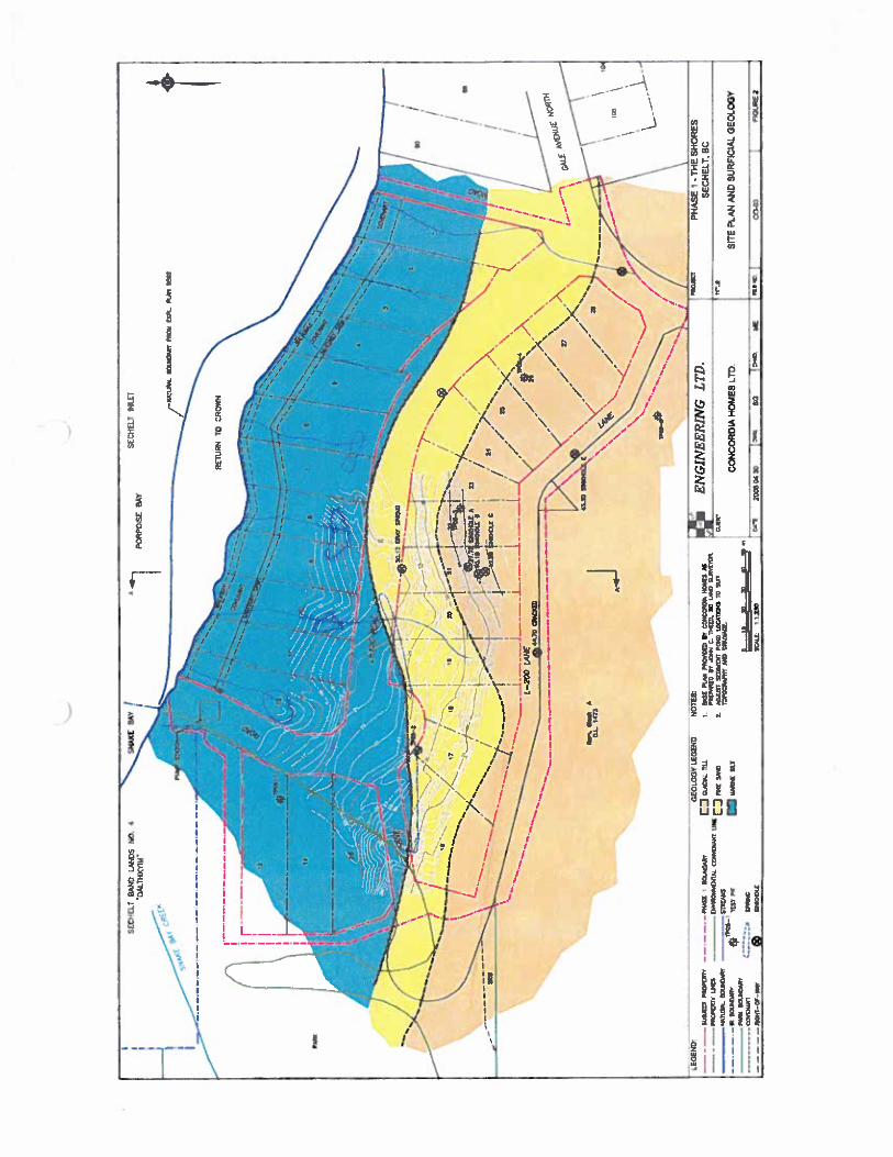
I.
(
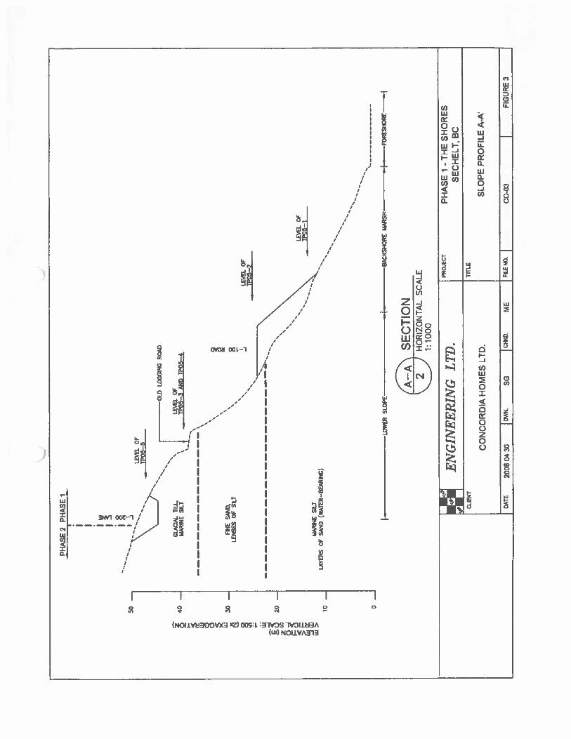
—--
/
PHA
SE2
PHA
SEt
LEVE
LO
FP0
5—1
0
LOW
ERSL
OPE
SEC
TIO
N
8PC
KSH
0RE
WR
SHI
FO
RE
SH
OR
E—
.j
HO
RZ
0NT
AL
SCA
LE
1:1
00
0
I—
0JE
Cr
PH
AS
E-T
HE
SH
OR
ES
fl
EN
GIN
EE
RIN
GL
TD
.I
SEC
HE
LT
,B
CC
JEN
TITL
E
IC
ON
CO
RD
IAH
OM
ES
LTD
.S
LO
PE
PR
OF
ILE
A-A
DATE
2006
0430
Dht
l.SG
C*W
,M
EFI
LEN
o.co
-na
FIG
URE
3
‘U
i
OLE
LN
GR
D
GLAC
IAL
liL
t.I
LEVE
LO
FM
ARIN
ESI
LTf
lP05—
3fl
IDTP
O5—
4
So—
40 30--
20 10
2 C w (9 (3 4 §
flNE
Sfl
D,
LEN
SES
OF
SILT
8 -JLE
VEL
OF
—TP
O5—
2
MAR
iNE
SILT
LA
OFSA
RO(W
AlE
R-B
EAR
ING
)

e
IWZ METRO TES1 ir4G LABORATORIES LTD.OStl Curmgh Avenue. Burniby S.C.. VSJ 4W
________________
Tel: (804) 434-9111 Fax: 8O4) 43S-9060
FIELD DENSITYREPORT
CONCORDIA HOMES90 BOX 21027MAPLE RIDGE, BCV2X 1?7
ATTN: RON DAVIS
PROJECTNO. SC—lBCUENT CONCORDIA
PROJECT GALE AVE. NORTH 6603SOILS/CONSULTING
“THE S?!CRES” PH. 1 GALE AVE.NORTH 6600SECHELT
REPORT NO. 4 NO. OF DENSITIES 7 TESTED BY MY DATE TESTED 2307. Jul . 23
CONTftCTOR CONCORDIA HOMES LTD. TIME TESTED &00AREA LOT 29CONSTRUCTION TYPE S INKHOLE REr-IS DIAT ION
DENSITY ) REFERENCEMOISTURE
OVERSIZE1 DRY DENSITYCOMPCIONNUMBER LOCATION
jYPE F? !UMM!
t 1 SEE ATTACHED SKETCH 8.2 5.0 0.3 2085 2:10 99
2 SEE ATTACHED SKETCH 6.B 8.0 I 0.0 2060 2110
3 ATTACHED SKETCH 7.6 9.0 0O 2034 z:o’ 96
4 SEE ATTACHED SKETCH L6 8.0 D.C 2017 21:2
F
5 SEE ATTACHED SKETCH 8.2 8.0 3.0 2091 2110
LFIELDMETIIOD Nuclear ASTM 02922 SPECIFIEOCOMPACI1ON 95
I LABORATORYMETHOD Standard ?roctor .STM D698 LOWQENSITtES[NDiCATEDROCK CORRECTION METHOD NoneOVERSIZESGREENS2E Passing 3/4” — 19mm
COMMENTSTEST LOCATION 6 TO BE IE-TESTED. FILL BEYOND SINKHOLE ( SEE SKETCH) TO BEPLACED AND COMPACTED. EX:STING MATERIAL TO BE EMOVRD.
-I
Page 1 of 2 — 2007. Aug.15 METRO TESTING lABORATORIES LTD PER. ..
.
Reporting of these test results const,tutes a testing serwce on’. Engmeenng inteipretation or evaluation of test r6’roed only on written request.
TO
L.
c.CHOMES
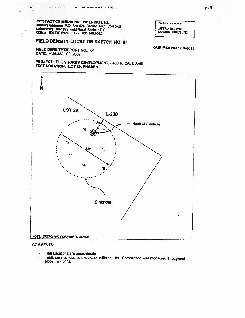
S.
GEOTACTICS MEDIA ENGINEERING LTD.Mailing Address: P.O. Bo 624, Secheit, B.C. ‘JON SADLaboratory: #4-1877 Field Road, Sechelt. B.C.Office: 604.740 0920 Fax: 604.740,0922
rssocannN0RAT0RIES LTD.
p.5
FIELD DENSITY LOCATION SKETCH NO.04
FIELD DENSITY REPORT NO.: 04DATE: AUGUST 2Q07
PROJECT: THE SHORES DEVELOPMENT,TEST LOCATION: LOT 29, PHASE I
6400 N. GALE AVE.
OUR FILE NO.; SC-QO18
NO TE: SKETCH NOT DRAk%Dg TO SC.4L
COMMENTS’
Test Locations are approximate- Tests were conducted on several different lifts. Compaction was monitored throughout
placement at nil,
LOT 29L-200
*5
Neck of Sinkhole
*7
Sinkhole
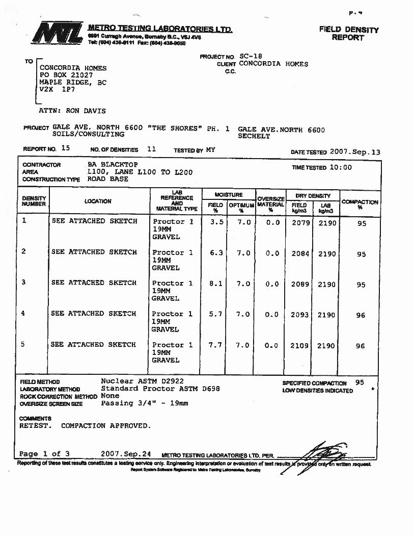
P.,
•
METRO TESTING LABORATORIES LTD.SQl Cingh Annu., Bwnaby B.C.. VSJ 4W
________________
Tel: (604) 4384111 Fec (104) 43aOO
FIELD DENSITYREPORT
TO[CONCORD TA HOMESPG BOX 21327MAPLE RIDGE, BCV2X 1P7
PROjECT N0 Sc— isCLICNT CONCORDIA HOMES
c-c.
ATTN: RON DAVIS
PROJECT GALE AVE. NORTH 6600SOLLS/CONSULTING
“THE SHORES” PH. 1 GALE AVE.NORPH 6600SECHELT
REPORTNO. 15 NO.OFDENSrnES 11 TESTEDOY MY D’QTErESTEO 2007.Sep. 13
CoNTRACTOR BA BLACKTOP TIMETESTED 1OO0jq LiDO, LANE LiDO TO L200CONSTRUCTION TYPE ROAD BASE
LAB MOISTURE DRY DENSITYREFERENCE OVERS4ZE COMPACTLONDENSITY LOCATION AND flELo OPT4UM MATERIAl. FIELD LA8NUMBER
MATERIAL TYPE q knJm kgl,n3
I. SEE ATTACHED SKETCH Proctor 1 3.5 7.0 0.0 2079 2190 951 9MMG RAVEL
2 SEE ATTACHED SKETCH Proctor 1 6.3 7.0 0.0 2084 2190 951. 9MMGRAVEL
3 SEE ATTACHED SKETCH Proctor 1 8.1 7.0 0.0 2089 2190 951 9MMGRAVEL
4 SEE ATTACHED SKETCH Proctor 1 5.7 7.0 0.0 2093 2190 961 9MMGRAVEL
5 SEE AnACHED SKETCH Proctor 1 7.7 7.0 0.0 2109 2190 9619MMGRAVEL
RELDMEThOD Nuclear ASTM D2922 SPECJFIEDCOMPACtION 95Lp.noaD.TORYMfl4oD Standard Proctor ASTM 3698 tOWDEMSITiESINDCATED *
ROCK COMRECTION METHOD NoneO1JERSIZESCREENSIZE Passing 3/4” - 19mm
COMMENTSRETEST. COMPACTION APPROVED.
Page 1 of 3 2007. Sep.24 METROTESIINGt.ASORATORIESLTD. PER.Rao’tfng of theta Intresdis nskftutea a (as ng aeMoo only. Englreedrg nwpre(aion cc evaluation of test rfluS)4ovjtdvCthllen mquL
eat Syn. Sot... agisWd o t.sfl Let., . &snty / ,,P

p.5
METRO TESTING LABORATORIES LTD.Sf1 Cunsgh Avanci. Burnaby B.C.. VSJ Va
________________
Tel; (0O4)436411t Fax: (604) 438.050
FIELD DENsyREPORT
TO[CONCORDIA HOMESP0 BOX 21027MAPLE RIDGE, BCV2X 1P7
PROJECTNO. SC—lBCLIENT CONCORDIA HOMES
c.c.
ATTN: RON DAVIS
PROJECT GALE AVE. NORTH 6600SOILS/CONSULTING
“THE SHORES” PH. 1 GALE AVE.NORTH 6600SECHELT
cowmcron BA BLACKTOP TIME TESTED 10:00AREA L100, LANE LiOG TO L200CO14STRUCTIO4 TYPE ROAD BASE
LAB j MOISTUREOVERSIZE
CRY DENSITYREFERENCE COMPAa,onD€NSITY LOCATION AN!) FIELD OPTIMUM MATERL4L FIELD LABNUMAERMATERIAL TYPE kgfm3 kgkn3
6 SEE ATTACHED SKETCH Proctor 1 7.4 7.0 0.0 2117 2190 9719MMGRAVEL
7 SEE ATTACHED SKETCH Proctor 1 5.8 7.0 0.0 2119 2190 971 9MMGRAVEL
8 SEE ATTACHED SKETCH Proctor 2. 5.2 7.0 0.0 2131 2190 971 9MMGRAVEL
9 SEE ATTACHED SKETCL-1 Proctor 1 5.0 7.0 0.0 2158 2190 991 9MMGRAVEL
10 SEE ATTACHED SKETCH Proctor 1 4.1 7.0 0.0 2117 2190 9719MMGRAVE:
naowmoo Nuclear ASTM 02922 SPECIFIEDCOMPACTION 95I.ASORATORYMrHOD Standard Proctor ASTM D698 LOWDEHSITIE$INDICATED *
ROCK CORRECT)ON METHOD NoneOVERSIZESCREENSIZE Passing 3/411
— 19mm
COMMENTSRETEST. COMPACTION APPROVED.
Page 2of 3 2007.Sep.24 METROTESTINGLABDRATORIESLTDPER.Repodlng of these lest resulle eanshiutes a testing service only. Engm.snng nrpretaUon evaluetfon of test resA gtov4ed4ionwnten request.
R.pon £l.m SOt.fl Rgsltc c ae.o rr.v Laonfses. D.snab .1
REPORT ND. 15 NO. OF DENSITiES 11 TESTED BY MY DATETESTED 2007.Sep.13

P.S
• METRO TESflNG LABORATORIES LTD.ISII Curngh Av.aue, Bum.by B.C., VSJ 4W
________________
Tel: (504) 4354111 Far (604)4364060
To(1CONCORDXA HOMES
Lv2x 1P7
P0 BOX 21027MAPLE RIDGE, BC
FIELD DENSITYREPORT
ATTN: RON DAVIS
PROJEGr GALE AVE. NORTH 6600SOILS/CONSULTING
“THE SHORES’ PH. 1 GALE AVE.NORTFf 6600SECHELT
REPORT NO. 15 NO. OF DENSITiES 11 TESTED BY MY DATETESTED 2007.Sep.13
CONTRACTOR BA BLACKTOP11100, LANE LiOG TO L200
OONSTRVC11ONTVPE ROAD BASE
DENNUMBER
Nuclear ASTM D2922 SPECIFIEDCOMPACTTON 95LABORATORYPEIKDO Standard Proctor ASTM 0698 LOWDENSITIESINOICATED *
ROCK CORRECTION METHOD NoneERSIZESCREENSIZE Passing 3/4” — 19mm
COMMENTSRETEST. COMPACTION APPROVED.
Page 3 of 3 2007.Sep.24 MEROTEST3NGLABORATORIESl.TD.PER..Repofling of Thsa st results awislitulas a tectW sepóce aily. Engineering k prflflon or evaluation of testru7kse9øfon*cfttan rew$sL
ftlcfl si’twn5i ernC M0 TeS’ LaB4fly
PROJECT NO. 5C18CIJENT CONCORDIA HOMES
e.G.
LOCATION
11 SEE ATTACHED SKETCH
TIMETESTED 10:00
Proctor19MMGRAVEL

p.7
off
a,p
£U)